JP5723582B2 - Method, program and system for configuring controller in sliding mode control system - Google Patents
Method, program and system for configuring controller in sliding mode control system Download PDFInfo
- Publication number
- JP5723582B2 JP5723582B2 JP2010267280A JP2010267280A JP5723582B2 JP 5723582 B2 JP5723582 B2 JP 5723582B2 JP 2010267280 A JP2010267280 A JP 2010267280A JP 2010267280 A JP2010267280 A JP 2010267280A JP 5723582 B2 JP5723582 B2 JP 5723582B2
- Authority
- JP
- Japan
- Prior art keywords
- control input
- hyperplane
- sliding mode
- linear
- controller
- Prior art date
- Legal status (The legal status is an assumption and is not a legal conclusion. Google has not performed a legal analysis and makes no representation as to the accuracy of the status listed.)
- Expired - Fee Related
Links
- 238000000034 method Methods 0.000 title claims description 29
- 238000005259 measurement Methods 0.000 claims description 19
- 238000013461 design Methods 0.000 claims description 12
- 238000005070 sampling Methods 0.000 claims description 12
- 230000004044 response Effects 0.000 claims description 9
- 238000012545 processing Methods 0.000 claims description 8
- 230000004069 differentiation Effects 0.000 claims description 4
- 241000196324 Embryophyta Species 0.000 description 20
- 238000004364 calculation method Methods 0.000 description 12
- 230000006870 function Effects 0.000 description 6
- 238000010586 diagram Methods 0.000 description 4
- 230000008569 process Effects 0.000 description 4
- 244000145845 chattering Species 0.000 description 2
- 238000002474 experimental method Methods 0.000 description 2
- 230000007246 mechanism Effects 0.000 description 2
- 230000003044 adaptive effect Effects 0.000 description 1
- 230000001364 causal effect Effects 0.000 description 1
- 238000005094 computer simulation Methods 0.000 description 1
- 238000011217 control strategy Methods 0.000 description 1
- 238000013480 data collection Methods 0.000 description 1
- 230000001934 delay Effects 0.000 description 1
- 230000000694 effects Effects 0.000 description 1
- 230000005484 gravity Effects 0.000 description 1
- 238000009499 grossing Methods 0.000 description 1
- 239000011159 matrix material Substances 0.000 description 1
- 238000005293 physical law Methods 0.000 description 1
- 238000013519 translation Methods 0.000 description 1
Images


Classifications
-
- G—PHYSICS
- G05—CONTROLLING; REGULATING
- G05B—CONTROL OR REGULATING SYSTEMS IN GENERAL; FUNCTIONAL ELEMENTS OF SUCH SYSTEMS; MONITORING OR TESTING ARRANGEMENTS FOR SUCH SYSTEMS OR ELEMENTS
- G05B13/00—Adaptive control systems, i.e. systems automatically adjusting themselves to have a performance which is optimum according to some preassigned criterion
- G05B13/02—Adaptive control systems, i.e. systems automatically adjusting themselves to have a performance which is optimum according to some preassigned criterion electric
- G05B13/0205—Adaptive control systems, i.e. systems automatically adjusting themselves to have a performance which is optimum according to some preassigned criterion electric not using a model or a simulator of the controlled system
-
- G—PHYSICS
- G05—CONTROLLING; REGULATING
- G05B—CONTROL OR REGULATING SYSTEMS IN GENERAL; FUNCTIONAL ELEMENTS OF SUCH SYSTEMS; MONITORING OR TESTING ARRANGEMENTS FOR SUCH SYSTEMS OR ELEMENTS
- G05B2219/00—Program-control systems
- G05B2219/30—Nc systems
- G05B2219/42—Servomotor, servo controller kind till VSS
- G05B2219/42343—Optimum, adaptive sliding mode controller
-
- G—PHYSICS
- G05—CONTROLLING; REGULATING
- G05B—CONTROL OR REGULATING SYSTEMS IN GENERAL; FUNCTIONAL ELEMENTS OF SUCH SYSTEMS; MONITORING OR TESTING ARRANGEMENTS FOR SUCH SYSTEMS OR ELEMENTS
- G05B2219/00—Program-control systems
- G05B2219/30—Nc systems
- G05B2219/42—Servomotor, servo controller kind till VSS
- G05B2219/42352—Sliding mode controller SMC, select other gain
Landscapes
- Engineering & Computer Science (AREA)
- Health & Medical Sciences (AREA)
- Artificial Intelligence (AREA)
- Computer Vision & Pattern Recognition (AREA)
- Evolutionary Computation (AREA)
- Medical Informatics (AREA)
- Software Systems (AREA)
- Physics & Mathematics (AREA)
- General Physics & Mathematics (AREA)
- Automation & Control Theory (AREA)
- Feedback Control In General (AREA)
Description
この発明は、スライディング・モード制御方式に関し、より詳しくは、スライディング・モード制御方式において、制御器を構成する方法、プログラム及びシステムに関する。 The present invention relates to a sliding mode control system, and more particularly, to a method, a program, and a system for configuring a controller in a sliding mode control system.
従来より、システムに含まれる非線形特性やパラメータ変動・負荷変動に対しても制御器(コントローラ)は十分にロバストであることが求められることが多い。これに対応する一つの解決策として、制御入力をスイッチングしながら制御対象の状態をあらかじめ設定した超平面に到達、拘束させ、その状態を平衡点に滑らせることにより、パラメータの不確定性、非線形性、雑音などに対して制御対象を安定化させるスライディング・モード制御(SMC) が多く用いられてきた。 Conventionally, controllers (controllers) are often required to be sufficiently robust against non-linear characteristics, parameter fluctuations, and load fluctuations included in the system. One solution to this is to switch the control input while reaching and constraining the state of the controlled object to the preset hyperplane and sliding the state to the equilibrium point, thereby making parameter uncertainty, nonlinearity In many cases, sliding mode control (SMC) that stabilizes an object to be controlled against noise and noise has been used.
例えば、衛星の位置・姿勢制御は、3次元空間での並進・回転の6自由度運動を行なうため、観測ターゲットの姿勢に衛星の姿勢を一致させ、その周りを一定の距離を保って周回するように位置制御するといった非線形方程式に対して、その変動不確定性に対応できる制御の必要がある。 For example, satellite position / attitude control moves in 6 degrees of freedom in translation and rotation in a three-dimensional space, so that the attitude of the satellite matches the attitude of the observation target and circulates around it at a constant distance. Thus, it is necessary to control the nonlinear equation such as position control so as to cope with the fluctuation uncertainty.
また、エンジンの排ガス規制に伴い、排気ガス再循環(EGR)機構などの精度良い制御のためにはオープン制御に基づく設計ではなく、多入力多出力系のフィードバック制御に基づくプラントモデルによる設計が必要となり、制御入力の区分的切替による可変構造系制御が必要とされる。 In addition, due to engine exhaust gas regulations, it is not necessary to design based on open control but to design based on plant model based on feedback control of multi-input multi-output system for precise control of exhaust gas recirculation (EGR) mechanism, etc. Therefore, variable structure control by piecewise switching of control inputs is required.
しかし、目標とする制御のためのSMCの導入決定についてはモデル設計者に依存することが多く、またその決定のためには多くの実験結果に基づいて非線形性が存在することを検証しなければならないことが課題であった。さらにSMCにおいて、非線形性は超平面への到達制御則で利用されるが、制御入力スイッチングの理想的瞬時切替を前提とした設計では制御入力にチャタリングが生じてしまう。これを回避するために各種の平滑化が用いられてきたが、空間を規定する非線形性が用いられていないことも問題であった。 However, the decision to introduce SMC for the target control often depends on the model designer, and for that decision, it must be verified that nonlinearity exists based on many experimental results. The problem was not to be. Furthermore, in SMC, nonlinearity is used in the control rule for reaching the hyperplane, but in the design based on ideal instantaneous switching of control input switching, chattering occurs in the control input. In order to avoid this, various smoothing methods have been used, but the non-linearity that defines the space is not used.
物理法則記述は一般に非線形となることが多いが、それを根拠に制御ストラテジーも非線形であるとして設計を進めることは制御器に無駄なコストを費やしかねない。また、SMCの必要性を検証するための実験データを多数収集する必要があることもコストを増加させる要因となっていた。さらに、非線形特性が生かされない到達制御則では十分な制御効果が得られない場合があり問題であった。 In general, the physical law description is often non-linear. However, if the control strategy is also non-linear based on the description, the controller may be costly wasted. In addition, it is necessary to collect a lot of experimental data for verifying the necessity of SMC, which is a factor that increases the cost. Furthermore, a reaching control law that does not make use of nonlinear characteristics has a problem in that a sufficient control effect may not be obtained.
特開平5−80805号公報は、従来の線形制御の技術を利用し、スライディングモード制御および適応制御を導入できるようにするために、スライディング・モードの位相面を、従来の線形制御で求められるトルク指令を積分ゲインK2で除した形とし、リアプノフ関数を制御対象のイナーシャ、動摩擦係数、重力項の推定値を考慮したものとし、該リアプノフ関数が常に負になるように、線形制御各ゲインKp,K1,K2を決め、上記各推定値を変化させて、補助入力を決める技法を開示する。 Japanese Patent Laid-Open No. 5-80805 uses a conventional linear control technique to introduce a sliding mode control and an adaptive control so that the phase plane of the sliding mode is a torque required by the conventional linear control. The command is divided by the integral gain K2, the Lyapunov function is assumed to take into account the inertia of the control object, the dynamic friction coefficient, and the estimated value of the gravity term, and the linear control gains Kp, A technique for determining auxiliary inputs by determining K1 and K2 and changing each of the estimated values will be disclosed.
特開2003−15703号公報は、制御対象であるプラントをモデル化してモデルパラメータの同定を行い、同定したモデルパラメータを用いてスライディングモード制御を行う場合の制御をより安定化することができるプラントの制御装置を提供するために、モデルパラメータ同定器が、モデルパラメータの基準ベクトルθbaseに更新ベクトルdθを加算する形式でモデルパラメータベクトルθの算出を行い、更新ベクトルdθの少なくとも1つの要素の過去値に0より大きく1より小さい所定値を乗算することにより、更新ベクトルdθを修正し、修正後の更新ベクトルdθを基準ベクトルθbaseに加算して、モデルパラメータベクトルθを算出することを開示する。 Japanese Patent Laid-Open No. 2003-15703 discloses a plant that can model a plant to be controlled and identify model parameters, and can further stabilize the control when performing sliding mode control using the identified model parameters. In order to provide the control device, the model parameter identifier calculates the model parameter vector θ in a form in which the update vector dθ is added to the reference vector θbase of the model parameter, and the past value of at least one element of the update vector dθ is obtained. Disclosed is to calculate the model parameter vector θ by correcting the update vector dθ by multiplying a predetermined value greater than 0 and less than 1 and adding the updated update vector dθ to the reference vector θbase.
また、「スライディングモード制御」野波健蔵、田宏奇著、コロナ社、1994年10月20日第1刷の3.1章には、切換超平面の設計技法が記述されており、3.2章には、スライディングモードコントローラの設計技法が記述されている。 "Sliding mode control" Kenzo Nonami, Hiroki Tana, Corona Company, October 20, 1994, Chapter 3.1 describes the design technique for switching hyperplanes. Describes a design technique for a sliding mode controller.
しかし、上記先行技術文献には、スライディング・モード制御の設計技法を開示するものの、スライディング・モード制御を適用すべきかどうかを簡易に判別する技法は示唆されていない。 However, although the prior art document discloses a design technique for sliding mode control, no technique for easily determining whether sliding mode control should be applied is suggested.
この発明の目的は、プラントにおいて、スライディング・モード制御を適用すべきかどうかを、必要最小限の計測実験データから自動判別することを可能ならしめる技法を提供することにある。 An object of the present invention is to provide a technique that makes it possible to automatically determine whether sliding mode control should be applied in a plant from the minimum necessary measurement experiment data.
本発明に従うシステムは先ず、プラントを、オープン制御的に計測する。そして、その計測データを用いて、既存のシステム同定手法と次数決定法により、プラントの状態方程式を記述する。さらにシステムは、システム同定されたプラントの状態方程式に基づき、スライディング・モード制御の切換超平面を設計する。 The system according to the invention first measures the plant in an open control manner. And the state equation of a plant is described by the existing system identification method and order determination method using the measurement data. In addition, the system designs a sliding hyperplane for sliding mode control based on the system's identified state equation.
システムは次に、超平面に拘束された時のノミナル・モデル、すなわち線形モデルの制御入力のみを用いた場合の出力と、スライディング・モードの制御入力を用いた場合の出力との間の差分について、高次統計量を計算する。そこでは特に、3次モーメントと、4次モーメントが計算される。そして、3次モーメントの値が所定の閾値より大きいかまたは、4次モーメントの値が所定の閾値より大きい場合、スライディング・モード制御が妥当であると判定して、4次モーメントの値を用いて、サンプリング時刻毎に係数が更新される非線形制御入力項を計算する。そしてシステムは、線形制御入力項と、非線形制御入力項の和として、制御器を構成する。 The system then determines the difference between the nominal model when constrained to the hyperplane, that is, the output when using only the linear model control input and the output when using the sliding mode control input. Calculate higher order statistics. In particular, the third and fourth moments are calculated. If the value of the third moment is larger than the predetermined threshold value or the value of the fourth moment is larger than the predetermined threshold value, it is determined that the sliding mode control is appropriate, and the value of the fourth moment is used. The nonlinear control input term whose coefficient is updated at every sampling time is calculated. The system then configures the controller as the sum of the linear control input term and the nonlinear control input term.
一方、3次モーメントの値と4次モーメントの値がどちらも、所定の閾値より小さいと判定した場合、システムは、線形制御入力項のみを用いて制御器を構成する。 On the other hand, if it is determined that the value of the third moment and the value of the fourth moment are both smaller than the predetermined threshold, the system configures the controller using only the linear control input term.
本発明によれば、スライディング・モード制御導入の妥当性を、必要最小限の計測データから判別できるため、データ収集実験を繰り返す必要がなくなる。また、それを判別する際に利用する統計量に基づき、従来よりも適切な制御器の設計が可能となる。 According to the present invention, the validity of introducing the sliding mode control can be determined from the minimum necessary measurement data, so that it is not necessary to repeat the data collection experiment. In addition, it is possible to design a controller that is more appropriate than the conventional one based on the statistic used to determine this.
さらに、本発明によれば、衛星など高速スイッチング機能などの搭載が難しいシステムに対しても、チャタリングを回避でき、不測の擾乱に対しても安価な制御器で安定した制御が可能となる。 Furthermore, according to the present invention, chattering can be avoided even for a system that is difficult to mount, such as a high-speed switching function such as a satellite, and stable control can be performed with an inexpensive controller against unexpected disturbances.
以下、図面に従って、本発明の実施例を説明する。これらの実施例は、本発明の好適な態様を説明するためのものであり、発明の範囲をここで示すものに限定する意図はないことを理解されたい。また、以下の図を通して、特に断わらない限り、同一符号は、同一の対象を指すものとする。 Embodiments of the present invention will be described below with reference to the drawings. It should be understood that these examples are for the purpose of illustrating preferred embodiments of the invention and are not intended to limit the scope of the invention to what is shown here. Further, throughout the following drawings, the same reference numerals denote the same objects unless otherwise specified.
図1を参照すると、本発明に従い制御器118を制御するための制御コンピュータのハードウェアのブロック図が示されている。図1において、システム・バス102には、CPU104と、主記憶(RAM)106と、ハードディスク・ドライブ(HDD)108と、キーボード110と、マウス112と、ディスプレイ114が接続されている。CPU104は、好適には、32ビットまたは64ビットのアーキテクチャに基づくものであり、例えば、インテル社のPentium(商標)4、インテル社のCore(商標) 2 DUO、AMD社のAthlon(商標)などを使用することができる。主記憶106は、好適には、2GB以上の容量、より好ましくは、4GB以上の容量をもつものである。
Referring to FIG. 1, a block diagram of the control computer hardware for controlling the
ハードディスク・ドライブ108には、個々に図示しないが、オペレーティング・システム及び本発明に係る処理プログラムなどが、予め格納されている。オペレーティング・システムは、Linux(商標)、マイクロソフト社のWindows(商標) 7、Windows XP(商標)、Windows(商標)2000、アップルコンピュータのMac OS(商標)などの、CPU104に適合する任意のものでよい。
The
キーボード110及びマウス112は、オペレーティング・システムが提供するグラフィック・ユーザ・インターフェースに従い、ディスプレイ114に表示されたアイコン、タスクバー、ウインドウなどのグラフィック・オブジェクトを操作するために使用される。キーボード110及びマウス112はまた、後述するデータは記録用プログラムを操作するためにも使用される。
The
ディスプレイ114は、これには限定されないが、好適には、1024×768以上の解像度をもち、32ビットtrue colorのLCDモニタである。ディスプレイ114は、例えば、制御器118の制御によるプラント120の動作の波形などを表示するために使用される。
The
ハードディスク・ドライブ108にはさらに、後述する計測モジュール204、システム同定モジュール206、高次統計量計算モジュール208、非線形制御入力項計算モジュール210、制御器構成モジュール212及び、全体の処理を統合するメイン・プログラム202が格納されている。これらのモジュールは、C、C++、C#、Java(R)などの既存の任意のプログラミング言語で作成することができる。これらのモジュールは、オペレーティング・システムの働きで適宜主記憶106にロードされて実行される。図示しないが、メイン・プログラム202は、適当なGUIにより、オペレータが操作するためのウィンドウをディスプレイ114に表示し、オペレータがキーボード110及びマウス112などを使って処理を開始し、あるいは停止することができる。
The
バス102にはさらに、PCI、USBなどの適当なインターフェース・ボード116を介して、制御器118と、プラント120が接続されている。制御器118は、インターフェース・ボード116を通じて、計算の結果得られた制御入力を設定可能なレジスタをもつ。
Further, a
計測モジュール204は、バス102及びインターフェース・ボード116を介して、プラント120に対して一連の信号を供給し、その応答を計測する機能をもつ。
The
システム同定モジュール206は、これには限定されないが、例えば、パラメトリック・モデルで状態方程式を用いるシステム同定法を使用する。パラメトリック・モデルの場合、構造決定ステップとして、モデル次数決定処理も併せて行われる。次に、予測誤差法によりパラメータを推定したり、部分空間法などによって状態空間モデルを推定するなどの処理を行う。システム同定モジュール206として、これには限定されないが、MATLAB(R)のSystem Identification Toolboxを利用することができる。システム同定モジュール206は、システム同定の結果、状態空間方程式を生成する。システム同定処理の詳細は例えば、「システム同定の基礎」足立修一著、東京電機大学出版局、2009年9月10日刊などを参照されたい。
The
さらにこの実施例では、システム同定モジュール206は、生成された状態空間方程式から、スライディング・モード制御用の切換長平面の式を設計する。なお、スライディング・モード制御用の切換長平面の設計については、「スライディングモード制御」野波健蔵、田宏奇著、コロナ社、1994年10月20日刊の3.1章などを参照されたい。
Furthermore, in this embodiment, the
高次統計量計算モジュール208は、プラント120の出力信号の高次統計量、特に3次モーメント及び4次モーメントを計算する機能を有する。
The high-order
非線形制御入力項計算モジュール210は、スライディング・モード制御特有の非線形制御入力項をサンプリング時刻毎に計算する機能を有する。この計算の際、高次統計量計算モジュール208で計算された4次モーメントの値が使用される。
The non-linear control input
制御器構成モジュール212は、システム同定されたノミナル・モデル、すなわち、超平面に拘束された場合の線形モデルに基づく制御入力項のみ、または、超平面に拘束された場合の線形モデルに基づく制御入力項及び非線形制御入力項の両方を使って、制御器118を構成する機能をもつ。
The
プラント120は例えば、自動車のエンジン、ブレーキ、エアコン、人工衛星など制御対象の機構装置である。
The
プラント120は、典型的には実機であるが、Simulink(R)、Modelicaなどのシミュレーション・モデリング・ツールで作成されたソフトウェア的なモデルであってもよい。プラント120がソフトウェア的なモデルである場合、ハードディスク・ドライブ108に格納されたモジュールとなり、すると、制御器118もハードディスク・ドライブ108に格納されたモジュールとなるので、インターフェース・ボード116を介したインターフェースは不要である。
The
次に、図3のフローチャートを参照して、図2の機能論理構成により実行される処理の詳細を説明する。 Next, details of processing executed by the functional logic configuration of FIG. 2 will be described with reference to the flowchart of FIG.
ステップ302では、メイン・プログラム202は、計測モジュール204を呼び出して、所定のサンプリング周期で計測信号を供給することにより、プラント120に対するオープン計測を行う。閉ループ計測だと、ある信号入力に対する因果関係が把握しにくいので、単純に計測信号に対する応答出力を把握するという意味で、オープン計測の方が望ましい。
In step 302, the
こうして応答出力が蓄積されると、メイン・プログラム202は、システム同定モジュール206を呼び出して、好適にはパラメトリック・モデルの使用と、それに続く次数決定技法により、プラント120の状態空間方程式を同定する。システム同定モジュール206は、こうして得られたプラント120の状態空間方程式から、スライディング・モード制御用の切換超平面を設計する。こうして、下記の式で記述されるモデルが得られる。
ここで、Xは入力、Yは、出力、Uは制御入力で、システム同定によって決定されたA、B、Cは係数行列である。また、σは切換超平面で、Sは、A、B、Cに基づき決定された、切換超平面を規定する行列である。
Once the response output has been accumulated, the
Here, X is an input, Y is an output, U is a control input, and A, B, and C determined by system identification are coefficient matrices. Further, σ is a switching hyperplane, and S is a matrix that defines the switching hyperplane determined based on A, B, and C.
ここで、メイン・プログラム202は、高次統計量計算モジュール208を呼び出し、ノミナル・モデル、すなわち超平面に拘束された場合の線形モデルの出力を
ylinear、当座のスライディング・モード制御モデルの出力をytempSMCとしたときの、データ観測列{s} = ytempSMC - ylinearを計算する。
Here, the
When y linear , the output of the current sliding mode control model is y tempSMC , the data observation sequence {s} = y tempSMC -y linear is calculated.
さらに、データ観測列{s}の平均値を計算して
![]()
とし、次のような平均値をゼロ化したデータ列{x}を計算する。
![]()
![]()
And calculate a data string {x} with zero average values as follows.
![]()
そして、高次統計量計算モジュール208は、データ列{x}を用いて、3次モーメント
![]()
と、
4次モーメント
を計算する。ここで、E[]は期待値であり、d1、d2、d3は、ラグまたは遅れである。
d1、d2、d3は、予め適当な値に決められており、例えば、d1 = d2 = d3 = 0でもよい。
Then, the higher-order
![]()
When,
4th moment
Calculate Here, E [] is an expected value, and d 1 , d 2 , and d 3 are lags or delays.
d 1 , d 2 , and d 3 are determined in advance to appropriate values. For example, d 1 = d 2 = d 3 = 0 may be used.
メイン・プログラム202は、このように計算された3次モーメントの値、及び4次モーメントの値を用いて、ステップ308で、スライディング・モード制御モデルの妥当性を判定する。
The
すなわち、メイン・プログラム202は、3次モーメントの値c3に対して閾値Th3を予め決め、4次モーメントの値c4に対しても閾値Th4を予め決め、
|c3| > Th3または、|c4| > Th4であると判定した場合に、スライディング・モード制御モデルを使用することが妥当であると判定する。一方、|c3| <= Th3且つ|c4| <= Th4である場合に、スライディング・モード制御モデルを使用することは妥当でないと判定する。
That is, the
When it is determined that | c 3 |> Th 3 or | c 4 |> Th 4, it is determined that it is appropriate to use the sliding mode control model. On the other hand, when | c 3 | <= Th 3 and | c 4 | <= Th 4 , it is determined that it is not appropriate to use the sliding mode control model.
メイン・プログラム202がステップ310で、スライディング・モード制御モデルを使用することは妥当でないと判定した場合、ステップ316に進み、メイン・プログラム202は、制御器構成モジュール212を呼び出して、下記の式に示す、超平面に拘束された場合の線形モデルの制御入力で制御器118を構成する。
![]()
![]()
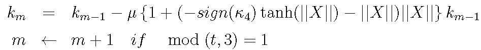
メイン・プログラム202がステップ310で、スライディング・モード制御モデルを使用することが妥当であると判定した場合、ステップ312に進み、メイン・プログラム202は、非線形制御入力項計算モジュール210を呼び出し、ステップ306で計算した4次モーメントを用いて、次の式に従い、サンプリング時間t毎に係数tが更新される制御入力の係数ktを計算する。
![]()
ここで、μはステップ定数で、例えば0.17である。sign()は、符号を返す関数である。また、κ4は、ステップ306で計算した4次モーメントであり、
一例では、κ4 = c4(0,0,0)である。この式は漸化式であり、サンプリング時刻の終了時にktが確定し、その値がkとして非線形制御入力項に使用される。
If the
![]()
Here, μ is a step constant, for example, 0.17. sign () is a function that returns a sign. Κ 4 is the fourth moment calculated in step 306,
In one example, κ 4 = c 4 (0,0,0). This expression is recurrence formula, k t is determined at the end of the sampling time, the value is used in the nonlinear control input term as k.
なお、係数ktは、サンプリング時間t毎の計算でなく、下記のようにtについて間引いて計算してもよい。
このような式は、超平面に至るまでの空間特性は高次モーメントの意味で偏りがあるので、それを考慮した勾配によって超平面に近づけるように制御すると、チャタリングが生じにくくなるという考察の下に決定されたものである。これは、ネゲントロピーの偏微分を近似した更新式という意味もある。説明を追加すると、これは、ノミナル・モデルからのスライディング・モード制御モデルとの乖離は、ガウス分布のエントロピーと状態量Xのノルムがもつエントロピーの差をゼロに近づけることに相当すると考慮した結果に基づく式である。この結果、非線形制御入力項は、次のように決定される。
![]()
In such an expression, the spatial characteristics up to the hyperplane are biased in the sense of higher-order moments. It has been decided. This also means an update formula approximating the partial differentiation of negentropy. If we add an explanation, this is because the difference between the nominal model and the sliding mode control model is equivalent to bringing the difference between the entropy of the Gaussian distribution and the norm of the state quantity X closer to zero. It is a formula based on. As a result, the nonlinear control input term is determined as follows.
![]()
メイン・プログラム202は、ステップ314で、制御器構成モジュール212を呼び出して、下記の式に示す、超平面に拘束された場合の線形モデルの制御入力項と、ステップ312で計算された非線形制御入力項の和で、制御器118を構成する。
![]()
![]()
図4は、このようにして構成された制御器118で、プラントを制御する様子を示す模式図である。制御器118の制御入力uが、プラント120にフィードバックされる。
FIG. 4 is a schematic diagram showing a state in which the plant is controlled by the
以上本発明の実施例を説明してきたが、本発明は、特定のハードウェア、ソフトウェアなどのプラット・フォームに限定されず、任意のプラット・フォーム上で実現可能であることを、この分野の当業者は理解するであろう。 Although the embodiments of the present invention have been described above, the present invention is not limited to specific hardware and software platforms, and can be implemented on any platform. The merchant will understand.
102 システム・バス
104 CPU
106 主記憶
108 ハードディスク・ドライブ
114 ディスプレイ
116 インターフェース・ボード
118 制御器
120 プラント
202 メイン・プログラム
204 計測モジュール
206 システム同定モジュール
208 高次統計量計算モジュール
210 非線形制御入力項計算モジュール
212 制御器構成モジュール
102
106
Claims (15)
前記プラントのオープン制御的計測によって、計測観測データ列を得るステップと、
前記計測値に基づき、システム同定技法により、前記プラントの状態空間方程式を記述し、スライディング・モード制御モデルのための切換超平面を設計するステップと、
前記観測データ列における、前記超平面上の線形モデルの出力と前記スライディング・モード制御モデル出力との間の差分について、3次統計量及び4次統計量を計算するステップと、
前記3次統計量又は前記4次統計量のどちらかが、それぞれ対応する所定の閾値より大きいことに応答して、前記4次統計量に基づいて、非線形制御入力項を計算し、前記超平面上での線形制御入力と、前記非線形制御入力との和によって制御器を構成するステップと、
前記3次統計量及び前記4次統計量の両方がそれぞれ対応する所定の閾値より小さいことに応答して、前記超平面上での線形制御入力によって、線形制御器を構成するステップとを有する、
スライディング・モード制御のための制御器を構成する方法。 In the sliding mode control system, a method of configuring a controller for a predetermined plant by computer processing,
Obtaining an observation data string by open control measurement of the plant;
Describing the state-space equations of the plant by system identification techniques based on the measurements and designing a switching hyperplane for a sliding mode control model;
Calculating third and fourth order statistics for the difference between the output of the linear model on the hyperplane and the output of the sliding mode control model in the observed data sequence;
Either of the third order statistics or the fourth-order statistics, respectively in response to greater than the corresponding predetermined threshold value, on the basis of the fourth order statistics, and calculates a nonlinear control input term, the hyperplane Configuring the controller by the sum of the linear control input above and the non-linear control input;
Configuring a linear controller with linear control inputs on the hyperplane in response to both the third order statistic and the fourth order statistic being less than a corresponding predetermined threshold value, respectively .
A method of configuring a controller for sliding mode control.
前記コンピュータに、
前記プラントのオープン制御的計測によって、計測観測データ列を得るステップと、
前記計測値に基づき、システム同定技法により、前記プラントの状態空間方程式を記述し、スライディング・モード制御モデルのための切換超平面を設計するステップと、
前記観測データ列における、前記超平面上の線形モデルの出力と前記スライディング・モード制御モデル出力との間の差分について、3次統計量及び4次統計量を計算するステップと、
前記3次統計量又は前記4次統計量のどちらかが、それぞれ対応する所定の閾値より大きいことに応答して、前記4次統計量に基づいて、非線形制御入力項を計算し、前記超平面上での線形制御入力と、前記非線形制御入力との和によって制御器を構成するステップと、
前記3次統計量及び前記4次統計量の両方がそれぞれ対応する所定の閾値より小さいことに応答して、前記超平面上での線形制御入力によって、線形制御器を構成するステップを実行させる、 スライディング・モード制御のための制御器を構成するプログラム。 In the sliding mode control system, a program for configuring a controller for a predetermined plant by computer processing,
In the computer,
Obtaining an observation data string by open control measurement of the plant;
Describing the state-space equations of the plant by system identification techniques based on the measurements and designing a switching hyperplane for a sliding mode control model;
Calculating third and fourth order statistics for the difference between the output of the linear model on the hyperplane and the output of the sliding mode control model in the observed data sequence;
Either of the third order statistics or the fourth-order statistics, respectively in response to greater than the corresponding predetermined threshold value, on the basis of the fourth order statistics, and calculates a nonlinear control input term, the hyperplane Configuring the controller by the sum of the linear control input above and the non-linear control input;
In response to both the third-order statistic and the fourth-order statistic being less than a corresponding predetermined threshold, respectively , causing a step of configuring a linear controller with a linear control input on the hyperplane; A program that configures a controller for sliding mode control.
前記プラントのオープン制御的計測によって、計測観測データ列を得る手段と、
前記計測値に基づき、システム同定技法により、前記プラントの状態空間方程式を記述し、スライディング・モード制御モデルのための切換超平面を設計する手段と、
前記観測データ列における、前記超平面上の線形モデルの出力と前記スライディング・モード制御モデル出力との間の差分について、3次統計量及び4次統計量を計算する手段と、
前記3次統計量又は前記4次統計量のどちらかが、それぞれ対応する所定の閾値より大きいことに応答して、前記4次統計量に基づいて、非線形制御入力項を計算し、前記超平面上での線形制御入力と、前記非線形制御入力との和によって制御器を構成する手段と、
前記3次統計量及び前記4次統計量の両方がそれぞれ対応する所定の閾値より小さいことに応答して、前記超平面上での線形制御入力によって、線形制御器を構成する手段を有する、
スライディング・モード制御のための制御器を構成するシステム。 In the sliding mode control system, a system for configuring a controller for a predetermined plant by computer processing,
Means for obtaining a measurement observation data string by open control measurement of the plant;
Means for describing the state-space equations of the plant based on the measurements and by system identification techniques to design a switching hyperplane for a sliding mode control model;
Means for calculating third and fourth order statistics for the difference between the output of the linear model on the hyperplane and the output of the sliding mode control model in the observed data sequence;
Either of the third order statistics or the fourth-order statistics, respectively in response to greater than the corresponding predetermined threshold value, on the basis of the fourth order statistics, and calculates a nonlinear control input term, the hyperplane Means for configuring the controller by the sum of the linear control input above and the non-linear control input;
Means for configuring a linear controller with linear control inputs on the hyperplane in response to both the third order statistic and the fourth order statistic being less than a corresponding predetermined threshold value, respectively .
A system that constitutes a controller for sliding mode control.
Priority Applications (2)
| Application Number | Priority Date | Filing Date | Title |
|---|---|---|---|
| JP2010267280A JP5723582B2 (en) | 2010-11-30 | 2010-11-30 | Method, program and system for configuring controller in sliding mode control system |
| US13/291,141 US8942832B2 (en) | 2010-11-30 | 2011-11-08 | Method, article of manufacture, and system for configuring controller in sliding-mode control scheme |
Applications Claiming Priority (1)
| Application Number | Priority Date | Filing Date | Title |
|---|---|---|---|
| JP2010267280A JP5723582B2 (en) | 2010-11-30 | 2010-11-30 | Method, program and system for configuring controller in sliding mode control system |
Publications (2)
| Publication Number | Publication Date |
|---|---|
| JP2012118718A JP2012118718A (en) | 2012-06-21 |
| JP5723582B2 true JP5723582B2 (en) | 2015-05-27 |
Family
ID=46127140
Family Applications (1)
| Application Number | Title | Priority Date | Filing Date |
|---|---|---|---|
| JP2010267280A Expired - Fee Related JP5723582B2 (en) | 2010-11-30 | 2010-11-30 | Method, program and system for configuring controller in sliding mode control system |
Country Status (2)
| Country | Link |
|---|---|
| US (1) | US8942832B2 (en) |
| JP (1) | JP5723582B2 (en) |
Cited By (2)
| Publication number | Priority date | Publication date | Assignee | Title |
|---|---|---|---|---|
| JPH0643704B2 (en) | 1985-04-24 | 1994-06-08 | 松下電工株式会社 | Waterproof floor pan |
| JP3194402B2 (en) | 1992-11-20 | 2001-07-30 | 凸版印刷株式会社 | Cosmetic material and manufacturing method thereof |
Families Citing this family (16)
| Publication number | Priority date | Publication date | Assignee | Title |
|---|---|---|---|---|
| US9329584B2 (en) * | 2011-12-15 | 2016-05-03 | International Business Machines Corporation | Method, system and program for constructing a controller |
| US8901871B2 (en) * | 2012-10-26 | 2014-12-02 | Woodward Hrt, Inc. | Robust controller for electro-mechanical actuators employing sliding and second control modes |
| US9292790B2 (en) * | 2012-11-20 | 2016-03-22 | Qualcom Incorporated | Piecewise linear neuron modeling |
| CN104614995B (en) * | 2015-02-16 | 2017-03-29 | 天津大学 | A kind of general design method of second-order system finite time sliding mode controller |
| JP2022524116A (en) * | 2019-03-19 | 2022-04-27 | 日本電気株式会社 | System identification device, system identification program and system identification method |
| CN111498147B (en) * | 2020-04-03 | 2021-09-21 | 哈尔滨工业大学(深圳)(哈尔滨工业大学深圳科技创新研究院) | Finite time segmentation sliding mode attitude tracking control algorithm of flexible spacecraft |
| CN111796568B (en) * | 2020-07-02 | 2022-02-11 | 北京航空航天大学 | Integral sliding mode control method, device and equipment for control system |
| CN112532299B (en) * | 2020-11-17 | 2022-06-03 | 上海利正卫星应用技术有限公司 | Satellite test automatic execution system based on module splicing |
| CN113777932B (en) * | 2021-11-15 | 2022-02-22 | 南京信息工程大学 | Four-rotor self-adaptive sliding mode fault-tolerant control method based on Delta operator |
| CN114509941B (en) * | 2022-01-12 | 2026-01-09 | 中国人民解放军军事科学院国防科技创新研究院 | UAV Flight Control Method Based on Adaptive Quasi-Optimal Higher-Order Sliding Mode Control |
| CN116449729B (en) * | 2023-04-07 | 2025-08-19 | 南京理工大学 | Dynamic response simulation method of rotating flexible beam based on SMC (sheet molding compound) partial coverage ACLD |
| CN121417517A (en) * | 2023-10-31 | 2026-01-27 | 云南电网有限责任公司电力科学研究院 | Phase shift angle control method, nonsingular sliding mode controller and wireless power transmission system |
| CN117706923B (en) * | 2023-12-11 | 2024-05-28 | 常州大学 | Method and system for controlling path tracking sliding mode of wheeled tractor with measurement noise |
| CN118311879B (en) * | 2024-06-07 | 2024-08-23 | 华东交通大学 | Feedback linearization-based under-actuated train sliding mode control method and related device |
| CN119336084B (en) * | 2024-12-17 | 2025-03-07 | 山东恒驰矿业装备科技有限公司 | Mine filling slurry concentration sliding mode control method and system |
| CN119527402A (en) * | 2025-01-21 | 2025-02-28 | 兰州交通大学 | Cooperative adaptive sliding mode control method for multiple trains in virtual marshaling based on extended state observer |
Family Cites Families (20)
| Publication number | Priority date | Publication date | Assignee | Title |
|---|---|---|---|---|
| GB9026735D0 (en) * | 1990-12-08 | 1991-01-30 | Vickers Systems Ltd | Sliding mode control system |
| JP2733881B2 (en) | 1991-09-19 | 1998-03-30 | ファナック株式会社 | Adaptive sliding mode control method based on PI control loop |
| JP3331159B2 (en) * | 1997-09-16 | 2002-10-07 | 本田技研工業株式会社 | Plant control equipment |
| JP2001115880A (en) * | 1999-10-19 | 2001-04-24 | Unisia Jecs Corp | Air-fuel ratio control device for internal combustion engine |
| JP2001117626A (en) * | 1999-10-20 | 2001-04-27 | Babcock Hitachi Kk | Plant-monitoring device |
| JP3339573B2 (en) * | 1999-11-01 | 2002-10-28 | 株式会社ユニシアジェックス | Diagnosis device for sliding mode control system |
| MY138476A (en) * | 2001-02-01 | 2009-06-30 | Honda Motor Co Ltd | Apparatus for and method of controlling plant |
| EP1293851B1 (en) * | 2001-04-20 | 2014-04-09 | Honda Giken Kogyo Kabushiki Kaisha | Plant control apparatus |
| JP3902504B2 (en) | 2001-04-20 | 2007-04-11 | 本田技研工業株式会社 | Plant control equipment |
| US6832149B2 (en) * | 2001-10-30 | 2004-12-14 | Toyota Jidosha Kabushiki Kaisha | Sliding mode controlling apparatus and sliding mode controlling method |
| JP3863069B2 (en) * | 2002-06-06 | 2006-12-27 | 本田技研工業株式会社 | Plant control equipment |
| JP2004287733A (en) * | 2003-03-20 | 2004-10-14 | Japan Research Institute Ltd | Parameter calculation method, status monitoring method, parameter calculation device, status monitoring device, status monitoring system, computer program, and recording medium |
| US7190140B2 (en) * | 2004-04-05 | 2007-03-13 | Sodick Co., Ltd. | Sliding mode controller position control device |
| JP4443985B2 (en) * | 2004-04-07 | 2010-03-31 | 本田技研工業株式会社 | Control device |
| JP4486901B2 (en) * | 2005-02-23 | 2010-06-23 | 本田技研工業株式会社 | Control device |
| EP2447792A1 (en) * | 2005-09-19 | 2012-05-02 | Cleveland State University | Controllers, observer, and applications thereof |
| US7453227B2 (en) * | 2005-12-20 | 2008-11-18 | Intuitive Surgical, Inc. | Medical robotic system with sliding mode control |
| JP4209435B2 (en) * | 2006-10-19 | 2009-01-14 | 本田技研工業株式会社 | Control device |
| JP4512610B2 (en) * | 2007-04-27 | 2010-07-28 | 本田技研工業株式会社 | Electronic control device for controlling plant temperature |
| US20110276150A1 (en) * | 2010-05-10 | 2011-11-10 | Al-Duwaish Hussain N | Neural network optimizing sliding mode controller |
-
2010
- 2010-11-30 JP JP2010267280A patent/JP5723582B2/en not_active Expired - Fee Related
-
2011
- 2011-11-08 US US13/291,141 patent/US8942832B2/en not_active Expired - Fee Related
Cited By (2)
| Publication number | Priority date | Publication date | Assignee | Title |
|---|---|---|---|---|
| JPH0643704B2 (en) | 1985-04-24 | 1994-06-08 | 松下電工株式会社 | Waterproof floor pan |
| JP3194402B2 (en) | 1992-11-20 | 2001-07-30 | 凸版印刷株式会社 | Cosmetic material and manufacturing method thereof |
Also Published As
| Publication number | Publication date |
|---|---|
| US20120136462A1 (en) | 2012-05-31 |
| US8942832B2 (en) | 2015-01-27 |
| JP2012118718A (en) | 2012-06-21 |
Similar Documents
| Publication | Publication Date | Title |
|---|---|---|
| JP5723582B2 (en) | Method, program and system for configuring controller in sliding mode control system | |
| EP3379349B1 (en) | Control device, control program, and control system | |
| Kali et al. | Discrete-time second order sliding mode with time delay control for uncertain robot manipulators | |
| Zheng et al. | A predictor-based framework for delay compensation in networked closed-loop systems | |
| Taflanidis et al. | Stochastic subset optimization for reliability optimization and sensitivity analysis in system design | |
| US20160055278A1 (en) | Method and Device for the Co-Simulation of Two Subsystems | |
| Niola et al. | Nonlinear estimation of the Bouc-Wen model with parameter boundaries: Application to seismic isolators | |
| CN108121204A (en) | A kind of self-adaptation control method and system of assembly spacecraft attitude model-free | |
| Yang et al. | A direct maximum likelihood optimization approach to identification of LPV time-delay systems | |
| JP5713338B2 (en) | Controller configuration method, system, and program | |
| CN118114553A (en) | Predictive control method of six-axis vibration table based on fuzzy neural equivalent input disturbance | |
| WO2016136630A1 (en) | System stability estimation device and system stability estimation method | |
| Gawthrop et al. | Bond graph based control and substructuring | |
| Verdonck et al. | Experimental robot identification: Advantages of combining internal and external measurements and of using periodic excitation | |
| Gao | Stable model order reduction method for fractional-order systems based on unsymmetric Lanczos algorithm | |
| Ager et al. | Adaptive robust backstepping control based on radial basis neural network for linear motor drives | |
| Aguilar-Ibanez et al. | Output feedback trajectory stabilization of the uncertainty DC servomechanism system | |
| CN114185268B (en) | A method, system and medium for controlling robot transmission resources with input hysteresis | |
| Mu et al. | Vibration‐energy‐optimal trajectory planning for flexible servomotor systems with state constraints | |
| Nguyen et al. | Integrating disturbance handling into control strategies for swing-up and stabilization of rotary inverted pendulum | |
| Gogilan et al. | Detection and characterization of local nonlinearity in a clamped‐clamped beam with state space realization | |
| US9329584B2 (en) | Method, system and program for constructing a controller | |
| Ullah et al. | Non integer order modeling and control of aerodynamic load simulator system | |
| Fang et al. | Hysteresis inverse-based tracking control of a class of hysteretic nonlinear systems with input and output delays | |
| Kanai et al. | Model predictive control with model error compensation by Koopman approach |
Legal Events
| Date | Code | Title | Description |
|---|---|---|---|
| A621 | Written request for application examination |
Free format text: JAPANESE INTERMEDIATE CODE: A621 Effective date: 20130903 |
|
| A977 | Report on retrieval |
Free format text: JAPANESE INTERMEDIATE CODE: A971007 Effective date: 20140626 |
|
| A131 | Notification of reasons for refusal |
Free format text: JAPANESE INTERMEDIATE CODE: A131 Effective date: 20140708 |
|
| A521 | Written amendment |
Free format text: JAPANESE INTERMEDIATE CODE: A523 Effective date: 20141001 |
|
| TRDD | Decision of grant or rejection written | ||
| A01 | Written decision to grant a patent or to grant a registration (utility model) |
Free format text: JAPANESE INTERMEDIATE CODE: A01 Effective date: 20150310 |
|
| A61 | First payment of annual fees (during grant procedure) |
Free format text: JAPANESE INTERMEDIATE CODE: A61 Effective date: 20150330 |
|
| R150 | Certificate of patent or registration of utility model |
Ref document number: 5723582 Country of ref document: JP Free format text: JAPANESE INTERMEDIATE CODE: R150 |
|
| LAPS | Cancellation because of no payment of annual fees |