JP5712870B2 - COMMUNICATION METHOD, COMMUNICATION DEVICE, AND COMMUNICATION PROGRAM - Google Patents
COMMUNICATION METHOD, COMMUNICATION DEVICE, AND COMMUNICATION PROGRAM Download PDFInfo
- Publication number
- JP5712870B2 JP5712870B2 JP2011188037A JP2011188037A JP5712870B2 JP 5712870 B2 JP5712870 B2 JP 5712870B2 JP 2011188037 A JP2011188037 A JP 2011188037A JP 2011188037 A JP2011188037 A JP 2011188037A JP 5712870 B2 JP5712870 B2 JP 5712870B2
- Authority
- JP
- Japan
- Prior art keywords
- address
- layer
- acquisition request
- arp
- response
- Prior art date
- Legal status (The legal status is an assumption and is not a legal conclusion. Google has not performed a legal analysis and makes no representation as to the accuracy of the status listed.)
- Expired - Fee Related
Links
Images


Classifications
-
- H—ELECTRICITY
- H04—ELECTRIC COMMUNICATION TECHNIQUE
- H04L—TRANSMISSION OF DIGITAL INFORMATION, e.g. TELEGRAPHIC COMMUNICATION
- H04L69/00—Network arrangements, protocols or services independent of the application payload and not provided for in the other groups of this subclass
- H04L69/22—Parsing or analysis of headers
-
- H—ELECTRICITY
- H04—ELECTRIC COMMUNICATION TECHNIQUE
- H04L—TRANSMISSION OF DIGITAL INFORMATION, e.g. TELEGRAPHIC COMMUNICATION
- H04L12/00—Data switching networks
- H04L12/02—Details
- H04L12/16—Arrangements for providing special services to substations
- H04L12/18—Arrangements for providing special services to substations for broadcast or conference, e.g. multicast
- H04L12/1863—Arrangements for providing special services to substations for broadcast or conference, e.g. multicast comprising mechanisms for improved reliability, e.g. status reports
-
- H—ELECTRICITY
- H04—ELECTRIC COMMUNICATION TECHNIQUE
- H04L—TRANSMISSION OF DIGITAL INFORMATION, e.g. TELEGRAPHIC COMMUNICATION
- H04L61/00—Network arrangements, protocols or services for addressing or naming
- H04L61/09—Mapping addresses
- H04L61/10—Mapping addresses of different types
- H04L61/103—Mapping addresses of different types across network layers, e.g. resolution of network layer into physical layer addresses or address resolution protocol [ARP]
-
- H—ELECTRICITY
- H04—ELECTRIC COMMUNICATION TECHNIQUE
- H04L—TRANSMISSION OF DIGITAL INFORMATION, e.g. TELEGRAPHIC COMMUNICATION
- H04L61/00—Network arrangements, protocols or services for addressing or naming
- H04L61/50—Address allocation
- H04L61/5007—Internet protocol [IP] addresses
- H04L61/5014—Internet protocol [IP] addresses using dynamic host configuration protocol [DHCP] or bootstrap protocol [BOOTP]
Landscapes
- Engineering & Computer Science (AREA)
- Computer Networks & Wireless Communication (AREA)
- Signal Processing (AREA)
- Computer Security & Cryptography (AREA)
- Small-Scale Networks (AREA)
- Data Exchanges In Wide-Area Networks (AREA)
Description
本発明は、通信方法、通信装置、および通信プログラムに関する。 The present invention relates to a communication method, a communication apparatus, and a communication program.
従来から、ネットワーク内の不特定多数の送信先に向けて、同一のデータを送信するブロードキャストを行う技術が存在する。たとえば、ARP(Address Resolution Protocol)では、レイヤ2アドレスの解決のために、ブロードキャストを行って通信相手のレイヤ2アドレスを取得する。ブロードキャストは、ネットワーク内の不特定多数に送信するため、ネットワークに大きな負荷を与えていた。
2. Description of the Related Art Conventionally, there is a technique for performing broadcast that transmits the same data to an unspecified number of destinations in a network. For example, in ARP (Address Resolution Protocol), in order to resolve a
ブロードキャストを抑制する技術として、たとえば、LAN(Local Area Network)に関し、通信回線で接続された集線装置において、接続された端末からのブロードキャストアドレスをユニキャストアドレスに変換するものがある。また、トンネル技術において、レイヤ2アドレス記憶機能を持つ中継装置を設け、ユーザ端末から取り込んだレイヤ2アドレスがブロードキャストアドレスとなるデータを、レイヤ3宛先アドレスに対応させた中継先トンネルにデータを送信する技術がある。
As a technique for suppressing broadcast, for example, with regard to a LAN (Local Area Network), there is a technique for converting a broadcast address from a connected terminal into a unicast address in a concentrator connected by a communication line. Also, in the tunnel technology, a relay device having a
また、アドレス解決要求に応じてアドレス解決結果を返送する探索サーバを有し、レイヤ2スイッチが、端末が発行するアドレス解決のためのマルチキャストパケットを認識時、探索サーバに所定ルートを通してマルチキャストパケットを転送する技術がある。また、無線LANにおいて、基地局内に、収容無線/優先端末にかかるレイヤ3アドレス、レイヤ2アドレス変換テーブルを持ち、送信先端末が変換テーブルに登録済みの場合、ブロードキャストアドレスをユニキャストアドレスに変換して送信する技術がある。
Also, it has a search server that returns the address resolution result in response to the address resolution request, and when the
しかしながら、上述した従来技術において、変換テーブルを用いてブロードキャストアドレスの変換を行うと、装置に対するレイヤ3アドレスが変更された場合、変更に対する対応が遅れて無効なデータが発行されることになり、ネットワークの負荷が増加する。また、ネットワークから装置が取り除かれた場合も、変更に対する対応が遅れ、ネットワークの負荷が増加する。また、変換テーブルを一定期間で消去すると、まだ変換が有効であったにも関わらずブロードキャストするため、ブロードキャストの抑制度合いが小さくなり、ネットワークの負荷が増加する。
However, in the above-described prior art, when the broadcast address is converted using the conversion table, when the
1つの側面では、本発明は、ネットワークの負荷を抑制できる通信方法、通信装置、および通信プログラムを提供することを目的とする。 In one aspect, an object of the present invention is to provide a communication method, a communication apparatus, and a communication program that can suppress a load on a network.
本発明の一側面によれば、ネットワーク内の装置群に設定されるレイヤ2アドレスとレイヤ3アドレスとの対応関係を記憶する記憶部にアクセス可能なコンピュータが、レイヤ2アドレスの取得要求を送信する場合、記憶部から、取得要求に含まれるレイヤ3アドレスに対応する第1のレイヤ2アドレスを抽出し、取得要求の宛先を、装置群を示す第2のレイヤ2アドレスから第1のレイヤ2アドレスに変換し、取得要求の宛先が変換された変換後の取得要求を送信し、変換後の取得要求に対応する応答を受信した場合、記憶部の第1のレイヤ2アドレスを応答に含まれる第1のレイヤ2アドレスで更新する通信方法、通信装置、および通信プログラムが提案される。
According to one aspect of the present invention, a computer that can access a storage unit that stores a correspondence relationship between a
また、本発明の他の側面によれば、ネットワーク内の装置群のうち、割当可能なレイヤ3アドレスを保持する装置の第1のレイヤ2アドレスを記憶する記憶部にアクセス可能なコンピュータが、レイヤ3アドレスの取得要求を受信し、取得要求に対応する第1の応答を送信する場合、記憶部から第1のレイヤ2アドレスと第1の応答から取得要求の送信元となる第2のレイヤ2アドレスとを抽出し、第1の応答に基づいて、宛先が第1のレイヤ2アドレスとなる第2の応答と、宛先が第2のレイヤ2アドレスとなる第3の応答と、を生成し、第2および第3の応答を送信する通信方法、通信装置、および通信プログラムが提案される。
According to another aspect of the present invention, a computer capable of accessing a storage unit that stores a
本発明の一態様によれば、ネットワークの負荷の抑制を図ることができる。 According to one embodiment of the present invention, network load can be suppressed.
以下に添付図面を参照して、開示の通信方法、通信装置、および通信プログラムの実施の形態を詳細に説明する。 Exemplary embodiments of a disclosed communication method, communication apparatus, and communication program will be described below in detail with reference to the accompanying drawings.
図1は、通信システムの動作例を示す説明図である。通信システム100は、本実施の形態1にかかる通信装置となるエンドホストサーバ(End Host Server:以下、「ES」と称する)1を含む。ES1は、内部にVM(Virtual Machine)1を含む。VMとは、コンピュータを仮想化し、複数のOSを実行できるように制御する仮想マシンモニタ上で動作する仮想マシンである。また、ES1は、ネットワーク101に接続しており、ネットワーク101内の装置群に設定されるレイヤ2アドレスとレイヤ3アドレスとの対応関係を記憶するARP_BtoUテーブル102_ES1にアクセス可能である。以下、“_ESx”は、ESxがアクセス可能なテーブルであることを示している。
FIG. 1 is an explanatory diagram illustrating an operation example of the communication system. The
この状態で、VM1が、レイヤ3アドレスであるIP(Internet Protocol)1に対するレイヤ2アドレスを取得するARPリクエストをブロードキャストで送信する。ES1は、ARP_BtoUテーブル102_ES1から、IP1に対応するMAC(Media Access Control)1を抽出し、ARPリクエストの宛先を、ブロードキャストアドレスからMAC1に変換し、ユニキャスト送信する。
In this state, the
ユニキャスト送信したARPリクエストに対するARPリプライを受信した場合、ES1は、ARP_BtoUテーブル102_ES1を、ARPリプライに含まれるMAC1で更新し、VM1にARPリプライを送信する。 When receiving the ARP reply for the ARP request transmitted by unicast, the ES1 updates the ARP_BtoU table 102_ES1 with the MAC1 included in the ARP reply, and transmits the ARP reply to the VM1.
このように、ES1は、ARPリクエストを行うブロードキャストを、記憶されたMACアドレスへのユニキャストに変換して送信し、ARPリプライで得たMACアドレスを更新する。これにより、ES1は、ブロードキャストを抑制し、また、ネットワーク変更に対応できるため、無効なデータの送信を行わないことから、ネットワーク101の負荷を抑制することができる。
In this way, the
図2は、通信システムの接続例を示す説明図である。通信システム100は、VM1〜VM10を含む。図2の例では、VM1、VM10は、ES1上で動作しており、VM2、VM3は、ES2上で動作している。VM4〜VM9についても、図2では図示していないが、何らかのES上で動作している。また、VM1〜VM10は、ネットワーク101を論理的に分離するLNID(Logical Network ID)が付与されている。(下記参考文献1参照)。
(参考文献1:スケーラブルなクラウドネットワークを実現する ホストベース論理分離技術、[online]、[平成23年08月15日検索]、インターネット<URL:http://skdr.dyndns.org/proceedings/sacsis2011/IPSJ−SACSIS2011013.pdf>)
FIG. 2 is an explanatory diagram illustrating a connection example of the communication system. The
(Reference 1: Host-based logical separation technology for realizing a scalable cloud network, [online], [searched on August 15, 2011], Internet <URL: http://skdr.dyndns.org/processedings/sacsis2011 /IPSJ-SACSSIS20110113.pdf>)
図2の例では、VM1、VM3、VM4、VM5、VM6、VM7に、LNID:1が付与されており、VM2、VM8、VM9、VM10に、LNID:2が付与されている。また、VM2〜VM9には、パケットをフィルタリングするフィルタリング装置を介してネットワーク101に接続されている。このような接続状況の元、たとえば、VM1は、ARPリクエストを、VSW(Virtual Switch)を介してVM2〜VM10にブロードキャストする。また、VM1は、IPアドレスを設定する場合、DHCP(Dynamic Host Configuration Protocol)に従って、DHCPDISCOVERをVM2〜VM10にブロードキャストする。
In the example of FIG. 2, LNID: 1 is assigned to VM1, VM3, VM4, VM5, VM6, and VM7, and LNID: 2 is assigned to VM2, VM8, VM9, and VM10. Further, the VM2 to VM9 are connected to the
(ES1のハードウェア)
図3は、ES1のハードウェアの一例を示すブロック図である。図3では、通信装置となるES1のハードウェアについて説明を行う。他のESもES1と同様のハードウェアを有する。図3において、ES1は、CPU(Central Processing Unit)301と、ROM(Read‐Only Memory)302と、RAM(Random Access Memory)303と、を含む。また、ES1は、磁気ディスクドライブ304と、磁気ディスク305と、光ディスクドライブ306と、光ディスク307と、を含む。また、ユーザやその他の機器との入出力装置としてES1は、ディスプレイ308と、I/F(Interface)309と、キーボード310と、マウス311と、を含む。また、各部はバス312によってそれぞれ接続されている。
(ES1 hardware)
FIG. 3 is a block diagram illustrating an example of hardware of the ES1. In FIG. 3, the hardware of the ES1 serving as a communication device will be described. Other ESs have the same hardware as ES1. In FIG. 3, the
ここで、CPU301は、ES1の全体の制御を司る。ROM302は、ブートプログラムなどのプログラムを記憶している。RAM303は、CPU301のワークエリアとして使用される。磁気ディスクドライブ304は、CPU301の制御に従って磁気ディスク305に対応するデータのリード/ライトを制御する。磁気ディスク305は、磁気ディスクドライブ304の制御で書き込まれたデータを記憶する。
Here, the
光ディスクドライブ306は、CPU301の制御に従って光ディスク307に対するデータのリード/ライトを制御する。光ディスク307は、光ディスクドライブ306の制御で書き込まれたデータを記憶したり、光ディスク307に記憶されたデータをコンピュータに読み取らせたりする。なお、ROM302、磁気ディスク305、光ディスク307のいずれかの記憶装置に、本実施の形態1,2にかかる通信プログラムが格納されていてもよい。
The
ディスプレイ308は、カーソル、アイコンあるいはツールボックスをはじめ、文書、画像、機能情報などのデータを表示する。たとえば、ディスプレイ308は、CRT、TFT液晶ディスプレイ、プラズマディスプレイなどを採用することができる。
The
I/F309は、通信回線を通じてLAN、WAN(Wide Area Network)、インターネットなどのネットワーク101に接続され、このネットワーク101を介して他の装置に接続される。そして、I/F309は、ネットワーク101と内部のインターフェースを司り、外部装置からのデータの入出力を制御する。I/F309には、たとえばモデムやLANアダプタなどを採用することができる。
The I /
キーボード310は、文字、数字、各種指示などの入力のためのキーを有し、データの入力を行う。また、キーボード310は、タッチパネル式の入力パッドやテンキーなどであってもよい。マウス311は、カーソルの移動や範囲選択、あるいはウィンドウの移動やサイズの変更などを行う。また、ES1は、マウス311の代わりとして、ポインティングデバイスとして同様に機能を有するものであれば、トラックボールやジョイスティックなどであってもよい。
The
(通信システム100の機能)
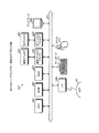
次に、通信システム100の機能について説明する。図4は、通信システムの機能例を示すブロック図である。通信システム100は、記憶部410と、抽出部411と、変換部412と、送信部413と、更新部414と、判定部415と、送信部416と、更新部417と、記憶部420と、受信部421と、抽出部422と、生成部423と、送信部424と、を含む。この制御部となる機能(抽出部411〜更新部417、受信部421〜送信部424)は、記憶装置に記憶されたプログラムをCPU301が実行することにより、その機能を実現する。記憶装置とは、具体的には、たとえば、図3に示したROM302、RAM303、磁気ディスク305、光ディスク307などである。または、I/F309を経由して他のCPUが実行することにより、その機能を実現してもよい。
(Function of communication system 100)
Next, functions of the
また、ES1は、記憶部410として、ARP_BtoUテーブル102_ES1と、DHCP_BtoUテーブル401_ES1にアクセス可能である。記憶部410は、RAM303、磁気ディスク305、光ディスク307等といった記憶装置内に存在している。同様に、ES2は、記憶部420として、DHCP_BtoUテーブル401_ES1にアクセス可能である。記憶部420は、ES2のRAM、磁気ディスク、光ディスク等といった記憶装置内に存在している。なお、ES2が、ARPリクエストを送信する場合、図4に示していないが、ES2はARP_BtoUテーブル102_ES2にアクセス可能であってもよい。
Further, the ES1 can access the ARP_BtoU table 102_ES1 and the DHCP_BtoU table 401_ES1 as the
また、図4では、記憶部410〜更新部417は、ES1の機能であることを示しており、記憶部420〜送信部424は、ES2の機能であることを示している。たとえば、ES1内のVMにDHCPサーバが起動している場合、ES1は、記憶部420〜送信部424を有していてもよい。また、図4では、ES1内にVM1が動作しており、ES2内にVM2、VM3が動作している。また、VM2にはDHCPサーバが起動している。
Further, in FIG. 4, the
ARP_BtoUテーブル102は、ネットワーク101内の装置群に設定されるレイヤ2アドレスとレイヤ3アドレスとの対応関係を記憶する。ここで、レイヤ2アドレスとは、データリンク層のアドレスであり、たとえば、MACアドレスである。また、レイヤ3アドレスとは、ネットワーク層のアドレスであり、たとえば、IPアドレスである。なお、ARP_BtoUテーブル102の詳細は、図5にて後述する。
The ARP_BtoU table 102 stores a correspondence relationship between the
DHCP_BtoUテーブル401_ES1は、割当可能なレイヤ3アドレスを保持する装置のレイヤ2アドレスを記憶する。具体的に、DHCP_BtoUテーブル401_ES1は、割当可能なレイヤ3アドレスを保持するDHCPサーバのMACアドレスを記憶する。
The DHCP_BtoU table 401_ES1 stores a
また、DHCP_BtoUテーブル401_ES1は、DHCPサーバのIPアドレスを記憶してもよい。特に、DHCPサーバが、ES1が属するブロードキャストドメインの外側に存在する場合、MACアドレスではES1からDHCPサーバに到達できないため、この場合、DHCP_BtoUテーブル401_ES1にDHCPサーバのIPアドレスを含める。また、DHCPサーバがES1の属するブロードキャストドメインの外側に存在する場合として、たとえば、DHCPリレーエージェントによって、VM1のブロードキャストデータを受けたルーターが、外側のDHCPサーバにデータを転送した場合である。なお、DHCP_BtoUテーブル401の詳細は、図25にて後述する。 Further, the DHCP_BtoU table 401_ES1 may store the IP address of the DHCP server. In particular, when the DHCP server exists outside the broadcast domain to which ES1 belongs, since the MAC address cannot reach the DHCP server from ES1, the IP address of the DHCP server is included in DHCP_BtoU table 401_ES1 in this case. The case where the DHCP server exists outside the broadcast domain to which ES1 belongs is, for example, the case where the router that received the broadcast data of VM1 by the DHCP relay agent transfers the data to the outside DHCP server. Details of the DHCP_BtoU table 401 will be described later with reference to FIG.
抽出部411は、レイヤ2アドレスの取得要求を送信する場合、記憶部410から、取得要求に含まれるレイヤ3アドレスに対応する第1のレイヤ2アドレスを抽出する機能を有する。たとえば、抽出部411は、レイヤ2アドレスの取得要求であるARPリクエストを送信する場合、ARP_BtoUテーブル102_ES1から、ARPリクエストに含まれる宛先プロトコルアドレスに対応するMACアドレスを抽出する。
When transmitting the acquisition request for the
また、抽出部411は、取得要求が割当可能なレイヤ3アドレスの取得要求であるときに、取得要求を送信する場合、記憶部410から第1のレイヤ2アドレスを抽出してもよい。具体的に、抽出部411は、レイヤ3アドレスの取得要求となるDHCPDISCOVERを送信する場合、DHCP_BtoUテーブル401_ES1から、DHCPサーバのMACアドレスを抽出する。
The extraction unit 411 may extract the
また、取得要求の取得方法としては、ES1内で生成された取得要求でもよいし、他のESから送信された取得要求を受信してもよい。なお、抽出された第1のレイヤ2アドレスは、RAM303、磁気ディスク305、光ディスク307などの記憶領域に記憶される。
In addition, as an acquisition request acquisition method, an acquisition request generated in the
変換部412は、取得要求の宛先を、ネットワーク101内の装置群を示す第2のレイヤ2アドレスから第1のレイヤ2アドレスに変換する機能を有する。第2のレイヤ2アドレスは、たとえば、ブロードキャストMACアドレスであり、“FF−FF−FF−FF−FF−FF”である。または、第2のレイヤ2アドレスは、マルチキャストMACアドレスであってもよく、たとえば、“01−00−5E−”で始まるMACアドレスである。
The conversion unit 412 has a function of converting the destination of the acquisition request from the
たとえば、変換部412は、ARPリクエストのヘッダ部分の宛先アドレスを、ブロードキャストMACアドレスから、抽出したMACアドレスに変換する。また、変換部412は、記憶部410に、抽出したレイヤ2アドレスに対応するレイヤ3アドレスが記憶されている場合、宛先IPアドレスを、抽出したレイヤ2アドレスに対応するレイヤ3アドレスに変換してもよい。なお、変換後の取得要求は、RAM303、磁気ディスク305、光ディスク307などの記憶領域に記憶される。
For example, the conversion unit 412 converts the destination address in the header part of the ARP request from the broadcast MAC address to the extracted MAC address. In addition, when the
送信部413は、取得要求の宛先が変換された変換後の取得要求を送信する機能を有する。たとえば、送信部413は、変換後となるユニキャストのARPリクエストをVM2に送信する。また、送信部413は、変換後のユニキャストのDHCPDISCOVERをVM2に送信する。
The
更新部414は、変換後の取得要求に対応する応答を受信した場合、記憶部410の第1のレイヤ2アドレスを、応答に含まれる第1のレイヤ2アドレスで更新する機能を有する。たとえば、更新部414は、ARPリプライを受信した場合、ARP_BtoUテーブル102_ES1のARPリクエストのIPアドレスに対応するMACアドレスを、ARPリプライの送信元ハードウェアアドレスで更新する。また、更新部414は、DHCPOFFERを受信した場合、DHCP_BtoUテーブル401_ES1にDHCPOFFERの送信元のMACアドレス、または、DHCPOFFERのサーバIPアドレスを登録する。
When receiving a response corresponding to the acquisition request after conversion, the
また、更新部414は、変換後の取得要求に対応する応答を受信しなかった場合、記憶部の第1のレイヤ2アドレスを削除してもよい。たとえば、更新部414は、ARPリプライを受信しなかった場合、ARP_BtoUテーブル102_ES1の、ARPリクエストに対応するレコードを削除する。たとえば、抽出部411において、抽出対象となったレコード番号を記憶しておき、ARPリプライを一定時間受信しなかった場合、更新部414は、記憶していたレコードを削除する。
Moreover, the
同様に、更新部414は、DHCPDISCOVERに対応するDHCPOFFERを受信しなかった場合、DHCP_BtoUテーブル401_ES1の、DHCPDISCOVERに対応するレコードを削除する。
Similarly, when the
判定部415は、第1のレイヤ2アドレスで更新した場合、第1のレイヤ2アドレスに対応するレイヤ3アドレスが記憶部410に複数存在するか否かを判定する機能を有する。たとえば、判定部415は、ARP_BtoUテーブル102_ES1が更新された結果、ARPリプライのMACアドレスと同一のMACアドレスとなるレコードが複数存在するか否かを判定する。なお、判定結果は、RAM303、磁気ディスク305、光ディスク307などの記憶領域に記憶される。
The determination unit 415 has a function of determining whether or not a plurality of
送信部416は、第1のレイヤ2アドレスに対応するレイヤ3アドレスが複数存在する場合、取得要求に含まれるレイヤ3アドレス以外となる残余のレイヤ3アドレスに対する擬似取得要求を、第1のレイヤ2アドレス宛てに送信する機能を有する。たとえば、送信部416は、ARPリプライのMACアドレスと同一のMACアドレスとなるレコードが複数存在した場合、ARPリクエストで行ったIPアドレス以外の残余のIPアドレスに対する擬似ARPリクエストを送信する。
When there are a plurality of
更新部417は、擬似取得要求に対応する応答を受信した場合、記憶部410の残余のレイヤ3アドレスに対応する第1のレイヤ2アドレスを擬似取得要求に対応する応答に含まれる第1のレイヤ2アドレスで更新する機能を有する。
When the
たとえば、擬似ARPリクエストに対するARPリプライを受信した場合を想定する。このとき、更新部417は、ARP_BtoUテーブル102_ES1のうち擬似ARPリクエストのIPアドレスに対応するMACアドレスを、ARPリプライの送信元ハードウェアアドレスで更新する。
For example, it is assumed that an ARP reply for a pseudo ARP request is received. At this time, the
また、更新部417は、擬似取得要求に対応する応答を受信しなかった場合、記憶部410の残余のレイヤ3アドレスに対応する第1のレイヤ2アドレスを削除してもよい。たとえば、更新部417は、ARP_BtoUテーブル102_ES1のうち擬似ARPリクエストのIPアドレスに対応するレコードを削除する。
Moreover, the
受信部421は、レイヤ3アドレスの取得要求を受信する機能を有する。たとえば、受信部421は、DHCPDISCOVERを受信する。なお、受信した取得要求は、ES2のRAM、磁気ディスク、光ディスクなどの記憶領域に記憶される。
The receiving
抽出部422は、取得要求に対応する第1の応答を送信する場合、記憶部420から第1のレイヤ2アドレスと第1の応答から取得要求の送信元となる第2のレイヤ2アドレスとを抽出する機能を有する。
When transmitting the first response corresponding to the acquisition request, the
たとえば、取得要求となるDHCPDISCOVERに対応する第1の応答として、ブロードキャストのDHCPOFFERを送信する場合を想定する。このとき、抽出部422は、DHCP_BtoUテーブル401_ES2からDHCPサーバのVM3のMACアドレスと、送信するDHCPOFFERからDHCPDISCOVERの送信元であるVM1のMACアドレスを抽出する。
For example, it is assumed that a broadcast DHCPOFFER is transmitted as a first response corresponding to DHCPDISCOVER serving as an acquisition request. At this time, the
また、取得要求となるDHCPREQUESTに対応する第1の応答として、ブロードキャストのDHCPACKを送信する場合を想定する。このとき、抽出部422は、DHCP_BtoUテーブル401_ES2から、DHCPサーバのVM3のMACアドレスと、送信するDHCPACKから、DHCPDISCOVERの送信元であるVM1のMACアドレスを抽出する。なお、抽出したレイヤ2アドレスは、ES2のRAM、磁気ディスク、光ディスクなどの記憶領域に記憶される。
Further, it is assumed that a broadcast DHCPACK is transmitted as a first response corresponding to DHCPREQUEST that is an acquisition request. At this time, the
生成部423は、第1の応答に基づいて、宛先が第1のレイヤ2アドレスとなる第2の応答と、宛先が第2のレイヤ2アドレスとなる第3の応答と、を生成する機能を有する。たとえば、生成部423は、ブロードキャストのDHCPOFFERを、宛先がVM3となる他のDPHCサーバへのユニキャストのDHCPOFFERと、宛先がVM1となるユニキャストのDHCPOFFERと、を生成する。また、生成部423は、ブロードキャストのDHCPACKを、宛先がVM3となる他のDPHCサーバとなるユニキャストのDHCPACKと、宛先がVM1となるユニキャストのDHCPACKと、を生成する。なお、生成した応答は、ES2のRAM、磁気ディスク、光ディスクなどの記憶領域に記憶される。
Based on the first response, the
送信部424は、第2および第3の応答を送信する機能を有する。たとえば、送信部424は、第2の応答をVM3に送信し、第3の応答をVM1に送信する。
The
図5は、ARPキャッシュテーブルとARP_BtoUテーブルの記憶内容の一例を示す説明図である。ARPを発行するVM1は、ARPによって得た、プロトコルアドレスと、ハードウェアアドレスとのマッピング情報を保持するARPキャッシュテーブル501_VM1を有する。プロトコルアドレスとは、ネットワーク層のプロトコルが用いる論理アドレスであり、たとえば、IPアドレスである。ハードウェアアドレスとは、データリンク層の物理アドレスであり、たとえば、MACアドレスである。本実施の形態では、プロトコルアドレスをIPアドレスであると想定し、ハードウェアアドレスをMACアドレスであると想定する。 FIG. 5 is an explanatory diagram showing an example of the contents stored in the ARP cache table and the ARP_BtoU table. The VM1 that issues the ARP has an ARP cache table 501_VM1 that holds mapping information between the protocol address and the hardware address obtained by the ARP. The protocol address is a logical address used by a network layer protocol, for example, an IP address. The hardware address is a physical address of the data link layer, for example, a MAC address. In this embodiment, it is assumed that the protocol address is an IP address and the hardware address is a MAC address.
ARPキャッシュテーブル501は、IP、MACという2つのフィールドを含む。IPフィールドには、IPアドレスが格納される。MACフィールドには、IPアドレスに関連付けられているMACアドレスが格納される。ARP_BtoUテーブル102は、ARPキャッシュテーブル501と同一のフィールドを有するため、説明を省略する。また、ARP_BtoUテーブル102は、LNIDを格納するフィールドを有していてもよい。 The ARP cache table 501 includes two fields, IP and MAC. An IP address is stored in the IP field. The MAC field stores a MAC address associated with the IP address. Since the ARP_BtoU table 102 has the same fields as the ARP cache table 501, description thereof is omitted. Further, the ARP_BtoU table 102 may have a field for storing the LNID.
たとえば、図5に示すARPキャッシュテーブル501_VM1は、“IP1”と“MAC1”を関連付けて記憶している。また、ARP_BtoUテーブル102は、“IP1”と“MAC1”を関連付けて記憶し、“IP2”と“未特定”を関連付けて記憶する。なお、“未特定”とは、ARPリクエストを送信した場合にMACフィールドに登録される識別子である。 For example, the ARP cache table 501_VM1 illustrated in FIG. 5 stores “IP1” and “MAC1” in association with each other. The ARP_BtoU table 102 stores “IP1” and “MAC1” in association with each other, and stores “IP2” and “unspecified” in association with each other. “Unspecified” is an identifier registered in the MAC field when an ARP request is transmitted.
なお、ARPキャッシュテーブル501_VM1は、レコードを保持する有効時間となるaging_timeが存在する。aging_timeを超えると、該当のレコードは削除される。 The ARP cache table 501_VM1 has an aging_time that is an effective time for holding a record. When exceeding aging_time, the corresponding record is deleted.
以下、ARP_BtoUテーブル102を用いて、ES1はARPブロードキャスト通信を抑制する。以下、図6〜図9では、ARPリクエストおよびARPリプライの受信時の動作を説明する。図10〜図14では、たとえば、DHCPのリース期限が切れた結果IPアドレスが再交付されたことにより、IPアドレスが置換される場合についての動作を説明する。図10、図15〜図18では、一つのインターフェースに二つ以上のアドレスを割り当てるIP aliasingが行われたことにより、1つのMACアドレスに新たなIPアドレスが追加された場合についての動作を説明する。 Hereinafter, using the ARP_BtoU table 102, ES1 suppresses ARP broadcast communication. In the following, with reference to FIG. 6 to FIG. 9, an operation when receiving an ARP request and an ARP reply will be described. 10 to 14, for example, the operation when the IP address is replaced due to the reassignment of the IP address as a result of the DHCP lease expiration will be described. 10 and 15 to 18, the operation when a new IP address is added to one MAC address by performing IP aliasing that assigns two or more addresses to one interface will be described. .
また、図19〜図22では、IPアドレスの割当が更新された結果、IPアドレスに対応するMACアドレスが変更する場合の動作について説明する。図23、図24では、BtoUテーブルへ最も効率よく登録される状態について説明する。 In addition, FIGS. 19 to 22 illustrate operations when the MAC address corresponding to the IP address is changed as a result of updating the assignment of the IP address. 23 and 24, the state that is most efficiently registered in the BtoU table will be described.
図6は、MACアドレス解決前にARPリクエストを受信した状態を示す説明図である。図6で示す通信システム100にて、ES1上のVM1は、MACアドレスとしてMAC1、IPアドレスとしてIP1が割り当てられている。さらに、ES2上のVM2は、MACアドレスとしてMAC2、IPアドレスとしてIP2が割り当てられており、ES2上のVM3は、MACアドレスとしてMAC3、IPアドレスとしてIP3が割り当てられている。また、ARPキャッシュテーブル501_VM1は何も登録されていない。
FIG. 6 is an explanatory diagram showing a state in which an ARP request is received before resolving the MAC address. In the
この状態で、VM1がIP2に対応するMACアドレスを尋ねるARPリクエストをブロードキャストで送信する。ARPリクエストを受信したES1は、ARPリクエストの送信元プロトコルアドレスと送信元ハードウェアアドレスから、ARP_BtoUテーブル102_ES1に、“IP1”、“MAC1”のレコードを追加する。さらに、ES1は、ARPリクエストの宛先プロトコルアドレスと宛先ハードウェアアドレスから、“IP2”、“未特定”のレコードを追加する。また、ES1は、ARPリクエストをVM2とVM3に送信する。 In this state, VM1 broadcasts an ARP request asking for a MAC address corresponding to IP2. The ES1 that has received the ARP request adds records “IP1” and “MAC1” to the ARP_BtoU table 102_ES1 from the transmission source protocol address and the transmission source hardware address of the ARP request. Further, the ES1 adds “IP2” and “unspecified” records from the destination protocol address and the destination hardware address of the ARP request. In addition, ES1 transmits an ARP request to VM2 and VM3.
図7は、MACアドレス解決前にARPリプライを受信した状態を示す説明図である。図7で示す通信システム100では、図6にて送信されたARPリクエストに対応して、VM2がMAC2を設定したARPリプライを送信した状態である。
FIG. 7 is an explanatory diagram showing a state in which an ARP reply is received before resolving the MAC address. In the
ARPリプライを受信したES1は、ARPリプライの送信元ハードウェアアドレスから、ARP_BtoUテーブル102_ES1の“IP2”のレコードのMACフィールドを、“MAC2”で更新する。また、ES1は、ARPリプライをVM1に送信する。VM1は、受信したAPRリプライから、ARPキャッシュテーブル501_VM1に“IP2”、“MAC2”のレコードを追加する。 The ES1 that has received the ARP reply updates the MAC field of the record “IP2” in the ARP_BtoU table 102_ES1 with “MAC2” from the transmission source hardware address of the ARP reply. In addition, ES1 transmits an ARP reply to VM1. From the received APR reply, the VM1 adds “IP2” and “MAC2” records to the ARP cache table 501_VM1.
図8は、MACアドレス解決後にARPリクエストを受信した状態を示す説明図である。図8で示す通信システム100では、図7にて受信したARPリプライからAging Timeが経過し、ARPキャッシュテーブル501_VM1から“IP2”、“MAC2”のレコードが削除された状態を示している。
FIG. 8 is an explanatory diagram showing a state in which an ARP request is received after MAC address resolution. In the
この状態で、VM1がIP2に対応するMACアドレスを尋ねるARPリクエストをブロードキャストで送信する。ARPリクエストを受信したES1は、ARP_BtoUテーブル102_ES1に、IP2に対するMAC2が登録されているため、通信方式をブロードキャストからMAC2に対するユニキャストに変換して、VM2に送信する。 In this state, VM1 broadcasts an ARP request asking for a MAC address corresponding to IP2. The ES1 that has received the ARP request, since MAC2 for IP2 is registered in the ARP_BtoU table 102_ES1, converts the communication method from broadcast to unicast for MAC2, and transmits it to VM2.
図9は、MACアドレス解決後にARPリプライを受信した状態を示す説明図である。図10で示す通信システム100では、図8にて送信されたARPリクエストに対応して、VM2がMAC2を設定したARPリプライを送信した状態である。
FIG. 9 is an explanatory diagram showing a state in which an ARP reply is received after MAC address resolution. In the
ARPリプライを受信したES1は、ARP_BtoUテーブル102_ES1にIP1に対するMAC1、IP2に対するMAC2が既に登録されているため、新たな登録をせず、ARPリプライをVM1に送信する。VM1は、受信したAPRリプライから、ARPキャッシュテーブル501_VM1に“IP2”、“MAC2”のレコードを追加する。 The ES1 that has received the ARP reply transmits the ARP reply to the VM1 without performing new registration because the MAC1 for IP1 and the MAC2 for IP2 are already registered in the ARP_BtoU table 102_ES1. From the received APR reply, the VM1 adds “IP2” and “MAC2” records to the ARP cache table 501_VM1.
図10は、IPアドレス置換時における動作とIPアドレス追加時における動作の初期状態を示す説明図である。図10で示す通信システム100では、VM1、VM2、VM3に割り当てられたIPアドレスとMACアドレスは、図6〜図9と同一である。また、ARP_BtoUテーブル102_ES1は、“IP1”と“MAC1”のレコードと、“IP2”と“MAC2”のレコードを記憶している。ARPキャッシュテーブル501_VM1は、“IP2”と“MAC2”のレコードを記憶している。この状態から、図11〜図14では、IPアドレスが置換される場合の動作について説明し、図15〜18では、IPアドレスが追加される場合の動作について説明を行う。
FIG. 10 is an explanatory diagram showing an initial state of an operation when replacing an IP address and an operation when adding an IP address. In the
図11は、IPアドレス置換時における動作を示す説明図(その1)である。図11で示す通信システム100では、図10で示した状態から、VM2に割り当てられたIPアドレスがIP2からIP4に置換された状態である。
FIG. 11 is an explanatory diagram (part 1) of the operation at the time of IP address replacement. In the
この状態で、VM1が、IP4に対応するMACアドレスを尋ねるARPリクエストをブロードキャストで送信する。ARPリクエストを受信したES1は、ARP_BtoUテーブル102_ES1に、IP4に対するMACアドレスが登録されていないため、ARPリクエストの通信方式をユニキャストに変換せずにブロードキャストとしてVM2、VM3に送信する。また、ES1は、ARP_BtoUテーブル102_ES1に“IP4”、“未特定”のレコードを追加する。
In this state, the
図12は、IPアドレス置換時における動作を示す説明図(その2)である。図12で示す通信システム100では、図8にて送信されたARPリクエストに対応して、VM2がMAC2を設定したARPリプライを送信した状態である。
FIG. 12 is an explanatory diagram (part 2) illustrating the operation at the time of IP address replacement. In the
ARPリプライを受信したES1は、ARPリプライの送信元ハードウェアアドレスから、ARP_BtoUテーブル102_ES1の“IP4”のレコードのMACフィールドを、“MAC2”で更新する。また、ES1は、ARPリプライをVM1に送信する。VM1は、受信したAPRリプライから、ARPキャッシュテーブル501_VM1に“IP4”、“MAC2”のレコードを追加する。 The ES1 that has received the ARP reply updates the MAC field of the record “IP4” in the ARP_BtoU table 102_ES1 with “MAC2” from the transmission source hardware address of the ARP reply. In addition, ES1 transmits an ARP reply to VM1. From the received APR reply, the VM1 adds “IP4” and “MAC2” records to the ARP cache table 501_VM1.
図13は、IPアドレス置換時における動作を示す説明図(その3)である。図13で示す通信システム100では、図12にてARPリプライを受信した後の状態を示している。MAC2に対するIPがIP2とIP4と、複数あるため、ES1は、IP2に対応するMACが本当にMAC2であるかを確認するために、擬似ARPリクエストをユニキャストで送信する。なお、擬似ARPリクエストとは、通常のARPリクエストと同内容ではあるが、VM1にて生成されたARPリクエストではなく、ES1にて生成されたARPリクエストである。
FIG. 13 is an explanatory diagram (part 3) illustrating the operation at the time of IP address replacement. In the
図14は、IPアドレス置換時における動作を示す説明図(その4)である。図14で示す通信システム100では、図13にて、VM2に擬似ARPリクエストを送信して一定時間が経過した状態である。VM2は、IP2が割り当てられていないため、IP2に対するARPリクエストに応答しない。
FIG. 14 is an explanatory diagram (part 4) illustrating the operation at the time of IP address replacement. In the
この状態で、ES1は、ARPリクエストに対するARPリプライが一定時間経過しても受信しない場合、ARP_BtoUテーブル102_ES1から、ARPリクエストの宛先プロトコルアドレスとなる“IP2”のレコードを削除する。このように、ES1は、IPアドレスが置換された場合、ARP_BtoUテーブル102_ES1のデータを、IPアドレスの割当状況に合わせて更新することができる。 In this state, if ES1 does not receive the ARP reply for the ARP request even after a predetermined time has passed, ES1 deletes the record “IP2” that is the destination protocol address of the ARP request from the ARP_BtoU table 102_ES1. In this way, when the IP address is replaced, ES1 can update the data in the ARP_BtoU table 102_ES1 according to the IP address allocation status.
図15は、IPアドレス追加時における動作を示す説明図(その1)である。図15で示す通信システム100では、図10の状態から、VM2のMAC2に新たにIP4が追加された状態である。
FIG. 15 is an explanatory diagram (part 1) illustrating an operation when an IP address is added. In the
この状態で、VM1がIP4に対応するMACアドレスを尋ねるARPリクエストをブロードキャストで送信する。ARPリクエストを受信したES1は、ARP_BtoUテーブル102_ES1に、IP4に対するMACアドレスが登録されていないため、ARPリクエストの通信方式をユニキャストに変換せずにブロードキャストとしてVM2、VM3に送信する。また、ES1は、ARP_BtoUテーブル102_ES1に“IP4”、“未特定”のレコードを追加する。
In this state, the
図16は、IPアドレス追加時における動作を示す説明図(その2)である。図16で示す通信システム100では、図15にて送信されたARPリクエストに対応して、VM2がMAC2を設定したARPリプライを送信した状態である。
FIG. 16 is an explanatory diagram (part 2) of the operation when adding an IP address. In the
ARPリプライを受信したES1は、ARPリプライの送信元ハードウェアアドレスから、ARP_BtoUテーブル102_ES1の“IP4”のレコードのMACフィールドを、“MAC2”で更新する。また、ES1は、ARPリプライをVM1に送信する。VM1は、受信したAPRリプライから、ARPキャッシュテーブル501_VM1に“IP4”、“MAC2”のレコードを追加する。 The ES1 that has received the ARP reply updates the MAC field of the record “IP4” in the ARP_BtoU table 102_ES1 with “MAC2” from the transmission source hardware address of the ARP reply. In addition, ES1 transmits an ARP reply to VM1. From the received APR reply, the VM1 adds “IP4” and “MAC2” records to the ARP cache table 501_VM1.
図17は、IPアドレス追加時における動作を示す説明図(その3)である。図17で示す通信システム100では、図16にてARPリプライを受信した後の状態を示している。MAC2に対するIPがIP2とIP4と、複数あるため、ES1は、IP2に対応するMACが本当にMAC2であるかを確認するために、擬似ARPリクエストをユニキャストで送信する。
FIG. 17 is an explanatory diagram (part 3) illustrating the operation when an IP address is added. In the
図18は、IPアドレス追加時における動作を示す説明図(その4)である。図18で示す通信システム100では、図17にて送信された擬似ARPリクエストに対応して、VM2がMAC2を設定したARPリプライを送信した状態である。
FIG. 18 is an explanatory diagram (part 4) illustrating the operation when an IP address is added. In the
ARPリプライを受信したES1は、ARPリプライの送信元ハードウェアアドレスから、ARP_BtoUテーブル102_ES1の“IP2”のレコードのMACフィールドを、“MAC2”で更新する。 The ES1 that has received the ARP reply updates the MAC field of the record “IP2” in the ARP_BtoU table 102_ES1 with “MAC2” from the transmission source hardware address of the ARP reply.
図19は、IPアドレスに対応するMACアドレスが変更する場合の動作を示す説明図(その1)である。図19で示す通信システム100は、IPアドレスの再割当が起こり、IPアドレスに対応するMACアドレスが変更する場合に説明する。図19で示す通信システム100にて、VM1は、MACアドレスとしてMAC1、IPアドレスとしてIP1が割り当てられている。さらに、ES2上のVM2は、MACアドレスとしてMAC2、IPアドレスとしてIP2が割り当てられており、ES2上のVM3は、MACアドレスとしてMAC3が割り当てられており、IPアドレスが割り当てられていない状態である。
FIG. 19 is an explanatory diagram (part 1) illustrating the operation when the MAC address corresponding to the IP address changes. The
また、ARP_BtoUテーブル102_ES1は、“IP1”と“MAC1”のレコードと、“IP2”と“MAC2”のレコードを記憶している。ARPキャッシュテーブル501_VM1は、“IP2”と“MAC2”のレコードを記憶している。 The ARP_BtoU table 102_ES1 stores records “IP1” and “MAC1” and records “IP2” and “MAC2”. The ARP cache table 501_VM1 stores “IP2” and “MAC2” records.
図20は、IPアドレスに対応するMACアドレスが変更する場合の動作を示す説明図(その2)である。図20で示す通信システム100では、図19で示した状態から、VM2のIPアドレスの割当が解除され、VM3にIP2が割り当てられた状態である。
FIG. 20 is an explanatory diagram (part 2) of the operation when the MAC address corresponding to the IP address changes. In the
この状態で、VM1がIP2に対応するMACアドレスを尋ねるARPリクエストをブロードキャストで送信する。ARPリクエストを受信したES1は、ARP_BtoUテーブル102_ES1に、IP2に対するMAC2が登録されているため、通信方式をブロードキャストからMAC2に対するユニキャストに変換して、VM2に送信する。また、ES1は、ARP_BtoUテーブル102_ES1に、IP2に対するMACを未特定に設定する。 In this state, VM1 broadcasts an ARP request asking for a MAC address corresponding to IP2. The ES1 that has received the ARP request, since MAC2 for IP2 is registered in the ARP_BtoU table 102_ES1, converts the communication method from broadcast to unicast for MAC2, and transmits it to VM2. Also, ES1 sets the MAC for IP2 to unspecified in the ARP_BtoU table 102_ES1.
図21は、IPアドレスに対応するMACアドレスが変更する場合の動作を示す説明図(その3)である。図21で示す通信システム100では、VM2にARPリクエストを送信して一定時間が経過した状態である。VM2は、IP2が割り当てられていないため、IP2に対するARPリクエストに応答しない。
FIG. 21 is an explanatory diagram (part 3) illustrating the operation when the MAC address corresponding to the IP address changes. In the
この状態で、ES1は、ARPリクエストに対するARPリプライが一定時間経過しても受信しない場合、IP2に対応するMACアドレスを尋ねるARPリクエストをブロードキャストで送信する。 In this state, if the ES1 does not receive the ARP reply for the ARP request after a predetermined time, the ES1 broadcasts an ARP request asking for the MAC address corresponding to IP2.
図22は、IPアドレスに対応するMACアドレスが変更する場合の動作を示す説明図(その4)である。図21で示す通信システム100では、図21にて送信されたAPRリクエストに対応して、VM3がMAC3を設定したARPリプライを送信した状態である。
FIG. 22 is an explanatory diagram (part 4) illustrating the operation when the MAC address corresponding to the IP address is changed. In the
ARPリプライを受信したES1は、ARPリプライの送信元ハードウェアアドレスから、ARP_BtoUテーブル102_ES1の“IP2”のレコードのMACフィールドを、“MAC3”で更新する。また、ES1は、ARPリプライをVM1に送信する。VM1は、受信したAPRリプライから、ARPキャッシュテーブル501_VM1に“IP2”、“MAC3”のレコードを追加する。このように、ES1は、IPアドレスに対するMACアドレスが変更された場合でも、ARP_BtoUテーブル102_ES1のデータを、IPアドレスの割当状況に合わせて更新することができる。 The ES1 that has received the ARP reply updates the MAC field of the record “IP2” in the ARP_BtoU table 102_ES1 with “MAC3” from the transmission source hardware address of the ARP reply. In addition, ES1 transmits an ARP reply to VM1. From the received APR reply, the VM1 adds “IP2” and “MAC3” records to the ARP cache table 501_VM1. Thus, ES1 can update the data of the ARP_BtoU table 102_ES1 in accordance with the IP address allocation status even when the MAC address for the IP address is changed.
図23は、ARP_BtoUテーブル使用の一例を示す説明図(その1)である。図23では、ARP_BtoUテーブルの使用例として、一回のARPリクエストによって同一ネットワーク101内のBtoUテーブルのエントリを取得できる例を示している。なお、図23、図24では、ES2内に、VM2、VM3に加えてVM4が存在し、VM4にMACアドレスとしてMAC4が割り当てられており、IPアドレスとしてIP4が割り当てられている。
FIG. 23 is an explanatory diagram (part 1) illustrating an example of using the ARP_BtoU table. FIG. 23 shows an example in which an entry of the BtoU table in the
初めに、処理(1)として、VM1は、IP2に対応するMACアドレスを尋ねるARPリクエストをブロードキャストで送信する。ARPリクエストを受信したES1は、ARP_BtoUテーブル102_ES1に、IP2に対するMACアドレスが登録されていないため、ARPリクエストの通信方式をユニキャストに変換せずにブロードキャストとしてVM2、VM3、VM4に送信する。また、ES1は、ARP_BtoUテーブル102_ES1に“IP1”、“MAC1”のレコードを追加する。また、ARPリクエストを受信したES2は、ARP_BtoUテーブル102_ES2に“IP1”、“MAC1”のレコードを追加する。
First, as process (1), the
次に、処理(2)として、VM2は、MAC2を設定したARPリプライを送信する。ARPリプライを受信したES2は、ARP_BtoUテーブル102_ES2に“IP2”、“MAC2”のレコードを追加する。また、ES2は、ARPリプライをVM1に送信する。ES1は、受信したAPRリプライから、ARP_BtoUテーブル102_ES1に“IP2”、“MAC2”のレコードを追加する。
Next, as process (2), the
図24は、ARP_BtoUテーブル使用の一例を示す説明図(その2)である。図24で示す通信システム100は、図23にて、ARPリクエストとARPリプライを送信した状態である。
FIG. 24 is an explanatory diagram (part 2) illustrating an example of using the ARP_BtoU table. The
この状態にて、処理(3)にて、VM3が、IP1に対応するMACアドレスを尋ねるARPリクエストをブロードキャストで送信する。ARPリクエストを受信したES2は、ARP_BtoUテーブル102_ES2に、IP1に対するMAC1が登録されているため、通信方式をブロードキャストからMAC1に対するユニキャストに変換して、VM1に送信する。また、ES2は、APRリクエストから、ARP_BtoUテーブル102_ES2に“IP3”、“MAC3”のレコードを追加する。ARPリクエストを受信したES1は、ARP_BtoUテーブル102_ES1に“IP3”、“MAC3”のレコードを追加する。また、ES1は、ARPリクエストをVM1に送信する。処理(4)にて、VM1は、ARPリプライをVM3に対して送信する。
In this state, in process (3), the
同様に、処理(5)にて、VM4が、IP1に対応するMACアドレスを尋ねるARPリクエストをブロードキャストで送信する。ARPリクエストを受信したES2は、ARP_BtoUテーブル102_ES2に、IP1に対するMAC1が登録されているため、通信方式をブロードキャストからMAC1に対するユニキャストに変換して、VM1に送信する。また、ES2は、ARPリクエストから、ARP_BtoUテーブル102_ES2に“IP4”、“MAC4”のレコードを追加する。ARPリクエストを受信したES1は、ARP_BtoUテーブル102_ES1に“IP4”、“MAC4”のレコードを追加する。また、ES1は、ARPリクエストをVM1に送信する。処理(6)にて、VM1は、ARPリプライをVM4に対して送信する。
Similarly, in process (5), the
このように、図23、図24では、処理(1)〜(3)、(5)における4つのARPフレームによって、VM1〜VM4に関する情報がBtoUテーブルに含まれたことになる。 As described above, in FIGS. 23 and 24, the information regarding VM1 to VM4 is included in the BtoU table by the four ARP frames in the processes (1) to (3) and (5).
図25は、DHCP_BtoUテーブルの記憶内容の一例を示す説明図である。DHCP_BtoUテーブル401は、DHCPサーバに関する情報を記憶する。DHCPサーバに関する情報として、図25で示すDHCP_BtoUテーブル401は、DHCPのMACアドレスを記憶している。また、DHCP_BtoUテーブル401は、各DHCPサーバのLNIDを格納するフィールドを有していてもよい。たとえば、ES1は、DHCP_BtoUテーブル401_ES1を有し、DHCP_BtoUテーブル401_ES1は、DHCPサーバのMACアドレスとして、“MAC1”と“MAC2”を記憶している。 FIG. 25 is an explanatory diagram of an example of the contents stored in the DHCP_BtoU table. The DHCP_BtoU table 401 stores information related to the DHCP server. As information regarding the DHCP server, the DHCP_BtoU table 401 shown in FIG. 25 stores the MAC address of the DHCP. Further, the DHCP_BtoU table 401 may have a field for storing the LNID of each DHCP server. For example, the ES1 has a DHCP_BtoU table 401_ES1, and the DHCP_BtoU table 401_ES1 stores “MAC1” and “MAC2” as the MAC address of the DHCP server.
以下、DHCP_BtoUテーブル401を用いて、ES1はARPブロードキャスト通信を抑制する。以下、図26〜図29では、DHCPDISCOVERを受信した場合の動作を説明する。また、図30〜図32では、ネットワーク内にある複数のDHCPサーバのうち、一つのDHCPサーバが停止中にDHCPDISCOVERを受信した場合の動作を説明する。 Hereinafter, using the DHCP_BtoU table 401, ES1 suppresses ARP broadcast communication. Hereinafter, with reference to FIG. 26 to FIG. 29, an operation when DHCPDISCOVER is received will be described. In addition, FIGS. 30 to 32 illustrate operations when DHCPDISCOVER is received while one DHCP server is stopped among a plurality of DHCP servers in the network.
図26は、DHCPサーバ登録前にDHCPDISCOVERを受信した状態を示す説明図(その1)である。図26で示す通信システム100では、ES1上のVM1は、MACアドレスとしてMAC1、IPアドレスとしてIP1が割り当てられている。また、ES2上のVM2、VM3、VM4は、MACアドレスとして、それぞれMAC2、MAC3、MAC4が割り当てられており、IPアドレスとして、それぞれ、IP2、IP3、IP4が割り当てられている。さらに、VM2、VM3では、それぞれ、DHCPサーバ2、DHCPサーバ3が起動している。また、DHCP_BtoUテーブル401_ES1とDHCP_BtoUテーブル401_ES2は何も登録されていない。
FIG. 26 is an explanatory diagram (part 1) illustrating a state in which DHCPDISCOVER has been received before DHCP server registration. In the
この状態で、VM1のDHCPクライアントがネットワーク内からDHCPサーバを検出するDHCPDISCOVERをブロードキャストで送信する。DHCPDISCOVERを受信したES1は、DHCP_BtoUテーブル401_ES1に何も登録されていないため、DHCPDISCOVERの通信方式をユニキャストに変換せずにブロードキャストのままVM2〜VM4に送信する。 In this state, the DHCP client of VM1 transmits a DHCPDISCOVER that detects a DHCP server from the network by broadcast. The ES1 that has received the DHCPDISCOVER is not registered in the DHCP_BtoU table 401_ES1, and therefore transmits the communication method of the DHCPDISCOVER to the VM2 to the VM4 while broadcasting without converting it to unicast.
図27は、DHCPサーバ登録前にDHCPDISCOVERを受信した状態を示す説明図(その2)である。図27で示す通信システム100では、図26にて送信されたDHCPDISCOVERに対して、DHCPサーバ2とDHCPサーバ3が、対応するDHCPOFFERを送信した状態である。
FIG. 27 is an explanatory diagram (part 2) illustrating a state in which DHCPDISCOVER is received before DHCP server registration. In the
この状態で、ES2は、VM2のDHCPサーバ2がDHCPDISCOVERに対するDHCPOFFERを受信する。ES2は、DHCP_BtoUテーブル401_ES2に何も登録されていないため、DHCPOFFERの通信方式をユニキャストに変換せずにブロードキャストのままVM1、VM3、VM4に送信する。また、ES2は、VM2のMACアドレスをDHCP_BtoUテーブル401_ES2に追加する。また、ES2は、VM3からのDHCPOFFERも同様に処理する。
In this state, the ES2 receives the DHCPOFFER for the DHCPDISCOVER by the
図28は、DHCPサーバ登録後にDHCPDISCOVERを受信した状態を示す説明図(その1)である。図28で示す通信システム100では、図27にてDHCPサーバ2とDHCPサーバ3がDHCPOFFERを送信し、DHCP_BtoUテーブル401_ES1、DHCP_BtoUテーブル401_ES2にDHCPサーバの情報が登録された状態である。
FIG. 28 is an explanatory diagram (part 1) illustrating a state in which DHCPDISCOVER is received after DHCP server registration. In the
この状態で、VM1のDHCPクライアントが、再びDHCPDISCOVERをブロードキャストで送信する。DHCPDISCOVERを受信したES1は、DHCP_BtoUテーブル401_ES1にDHCPサーバの情報が登録されているため、DHCPDISCOVERの通信方式をブロードキャストからユニキャストに変換してVM2、VM3に送信する。具体的に、ES1は、宛先MACアドレスをブロードキャストアドレスからMAC2に変換したDHCPパケットをVM2に送信し、宛先MACアドレスをブロードキャストアドレスからMAC3に変換したDHCPパケットをVM3に送信する。 In this state, the DHCP client of VM1 again transmits DHCPDISCOVER by broadcast. Since the DHCP server information is registered in the DHCP_BtoU table 401_ES1, the ES1 that has received the DHCPDISCOVER converts the DHCPDISCOVER communication method from broadcast to unicast, and transmits it to the VM2 and VM3. Specifically, the ES1 transmits a DHCP packet in which the destination MAC address is converted from the broadcast address to MAC2 to the VM2, and transmits a DHCP packet in which the destination MAC address is converted from the broadcast address to MAC3 to the VM3.
図29は、DHCPサーバ登録後にDHCPDISCOVERを受信した状態を示す説明図(その2)である。図29で示す通信システム100では、図28にて送信されたDHCPDISCOVERに対して、VM2、VM3がDHCPOFFERを送信した状態である。
FIG. 29 is an explanatory diagram (part 2) illustrating a state in which DHCPDISCOVER is received after DHCP server registration. In the
この状態で、ES2は、VM2のDHCPサーバ2がDHCPDISCOVERに対するDHCPOFFERを受信する。ES2は、DHCP_BtoUテーブル401_ES2にDHCPサーバの情報が登録されているため、DHCPOFFERの通信方式をブロードキャストからユニキャストに変換して、DHCPサーバとDHCPDISCOVERの送信元に送信する。
In this state, the ES2 receives the DHCPOFFER for the DHCPDISCOVER by the
具体的に、ES1は、宛先MACアドレスをブロードキャストアドレスからMAC3に変換したDHCPパケットをVM3に送信する。また、ES1は、DHCPOFFERのクライアントハードウェアアドレスに格納されたDHCPDISCOVERの送信元となるMAC1を取得し、宛先MACアドレスをブロードキャストアドレスからMAC1に変換したDHCPパケットをVM1に送信する。また、ES2は、VM3からのDHCPOFFERも同様に処理する。 Specifically, the ES1 transmits a DHCP packet obtained by converting the destination MAC address from the broadcast address to the MAC3 to the VM3. Further, the ES1 acquires MAC1 as a transmission source of DHCPDISCOVER stored in the DHCPOFFER client hardware address, and transmits a DHCP packet in which the destination MAC address is converted from the broadcast address to MAC1 to the VM1. ES2 also handles DHCPOFFER from VM3 in the same way.
図30は、DHCPサーバの停止中にDHCPDISCOVERを受信した状態を示す説明図(その1)である。図30で示す通信システム100では、図29で示した状態から、DHCPサーバ3の動作が停止した状態である。図30の状態では、DHCP_BtoUテーブル401_ES1は、DHCPサーバのMACアドレスとして、MAC2とMAC3を記憶している。
FIG. 30 is an explanatory diagram (part 1) illustrating a state in which DHCPDISCOVER is received while the DHCP server is stopped. In the
図31は、DHCPサーバの停止中にDHCPDISCOVERを受信した状態を示す説明図(その2)である。図31で示す通信システム100では、図30の状態から、VM1がDHCPDISCOVERをブロードキャストで送信する状態である。
FIG. 31 is an explanatory diagram (part 2) illustrating a state in which DHCPDISCOVER is received while the DHCP server is stopped. In the
この状態で、ES1は、DHCP_BtoUテーブル401_ES1にDHCPサーバの情報が登録されているため、DHCPDISCOVERの通信方式をブロードキャストからユニキャストに変換してVM2、VM3に送信する。 In this state, since the information of the DHCP server is registered in the DHCP_BtoU table 401_ES1, the ES1 converts the DHCPDISCOVER communication method from broadcast to unicast and transmits it to the VM2 and VM3.
図32は、DHCPサーバの停止中にDHCPDISCOVERを受信した状態を示す説明図(その3)である。図32で示す通信システム100では、図28にて送信されたDHCPDISCOVERに対して、VM2がDHCPOFFERを送信した状態である。
FIG. 32 is an explanatory diagram (part 3) illustrating a state in which DHCPDISCOVER is received while the DHCP server is stopped. In the
この状態で、ES1は、VM3からのDHCPOFFERが一定時間に到達しない場合、DHCPサーバが停止したと判断し、DHCP_BtoUテーブル401_ES1内の該当する“MAC3”のレコードを削除する。このように、ES1は、DHCPサーバの停止に合わせて、DHCP_BtoUテーブル401_ES1のデータを更新することができる。 In this state, if the DHCPOFFER from the VM3 does not reach a certain time, the ES1 determines that the DHCP server has stopped, and deletes the corresponding “MAC3” record in the DHCP_BtoU table 401_ES1. Thus, ES1 can update the data in the DHCP_BtoU table 401_ES1 in accordance with the stop of the DHCP server.
図33は、ブロードキャストデータの破棄例を示す説明図である。たとえば、図6におけるVM1が、定期的にIPアドレスAに対するARPリクエストを送信している場合を想定する。このとき、ES1は、一定周期の間に、閾値より多い数分のIPアドレスに対するブロードキャストを破棄する。図25の例では、一定周期を100[ミリ秒]、閾値を3[回]として、宛先IPアドレスがAであるブロードキャストデータのうち、3個目までのデータを受付許可し、4回目からのデータの破棄を行っている。なお、ブロードキャストデータとして当てはまるのは、前述したARPフレーム、DHCPパケットである。また、ブロードキャストデータは、ARP、DHCP以外の他のプロトコルによって規定された、ブロードキャストを行うデータであってもよい。
FIG. 33 is an explanatory diagram of an example of discarding broadcast data. For example, assume that
また、図33の例では、ES1は、破棄するデータの数え上げを宛先IPアドレスごとに行っているが、送信元IPアドレスごと、または送信元IPアドレスと宛先IPアドレスの組ごとに行ってもよい。また、ES1は、IPアドレスでなく、MACアドレスに基づいて、破棄するデータの数え上げを行ってもよい。これにより、本実施の形態にかかるESは、異なるアドレスに対して初めて送信されるブロードキャストを破棄せずに済む。 In the example of FIG. 33, ES1 counts data to be discarded for each destination IP address. However, ES1 may perform it for each source IP address or each set of source IP address and destination IP address. . Further, the ES1 may count the data to be discarded based on the MAC address instead of the IP address. Thereby, the ES according to the present embodiment does not need to discard the broadcast transmitted for the first time to a different address.
続けて、図5〜図33で示した動作を行うフローチャートを説明する。図34〜図39では、ARPフレームに関するフローチャートを示し、図40〜図44では、DHCPパケットに関するフローチャートを示す。また、図34〜図44にて各フローチャートを実行する実行主体は各ESであるが、図34〜図44にて示すフローチャートでは、ES1を実行主体として説明を行う。 Next, a flowchart for performing the operation shown in FIGS. 34 to 39 show flowcharts related to the ARP frame, and FIGS. 40 to 44 show flowcharts related to the DHCP packet. 34 to 44, each execution entity that executes each flowchart is each ES. However, in the flowcharts illustrated in FIGS. 34 to 44, ES1 is described as an execution entity.
図34は、ARPフレーム処理の一例を示すフローチャートである。ES1は、ARPフレームを受信したか否かを判断する(ステップS3401)。ARPフレームを受信した場合(ステップS3401:Yes)、ES1は、一定期間に閾値以上、同一宛先アドレスへのARPフレームを受信したか否かを判断する(ステップS3402)。条件に当てはまらない場合(ステップS3402:No)、ES1は、ARPフレーム受信処理を実行する(ステップS3403)。ARPフレーム受信処理の詳細は、図36で後述する。 FIG. 34 is a flowchart illustrating an example of the ARP frame process. The ES1 determines whether or not an ARP frame has been received (step S3401). If an ARP frame has been received (step S3401: YES), ES1 determines whether or not an ARP frame to the same destination address has been received for a certain period of time or more (step S3402). If the condition is not satisfied (step S3402: NO), the ES1 executes an ARP frame reception process (step S3403). Details of the ARP frame reception processing will be described later with reference to FIG.
ARPフレーム受信処理の終了後、ES1は、ARPフレーム送信処理を実行する(ステップS3404)。ARPフレーム送信処理は、受信したARPフレームを、ARPフレーム受信処理内によって変換された宛先に送信する処理である。なお、ARPフレーム送信処理によって送信された後に応答がなかったフレームについての処理については、図35にて示す。
After the end of the ARP frame reception process, the
ARPフレーム送信処理の終了後、ES1は、ステップS3401の処理に移行する。また、条件に当てはまる場合(ステップS3402:Yes)、ES1は、受信したARPフレームを破棄して、ステップS3401の処理に移行する。また、ARPフレームを受信していない場合(ステップS3401:No)、ES1は、一定時間経過後、ステップS3401の処理を再び実行する。 After the end of the ARP frame transmission process, the ES1 proceeds to the process of step S3401. If the condition is satisfied (step S3402: YES), the ES1 discards the received ARP frame and proceeds to the process of step S3401. If an ARP frame has not been received (step S3401: NO), the ES1 executes the process of step S3401 again after a predetermined time has elapsed.
図35は、ARP送信タイムアウト処理の一例を示すフローチャートである。ES1は、ARPリクエストに対応するARPリプライが到達しない状態が一定時間経過したか否かを判断する(ステップS3501)。なお、ステップS3501の処理における一定時間として、たとえば、ARPの仕様にて定められた再送時間等に設定してもよいし、仕様にて定められた再送時間より短くしてもよい。 FIG. 35 is a flowchart illustrating an example of the ARP transmission timeout process. The ES1 determines whether or not a certain time has passed in a state where the ARP reply corresponding to the ARP request has not arrived (step S3501). Note that the fixed time in the process of step S3501 may be set to, for example, a retransmission time defined in the ARP specification, or may be shorter than the retransmission time defined in the specification.
一定時間経過した場合(ステップS3501:Yes)、ES1は、ARP_BtoUテーブル102_ES1のうち、ARPリプライが到達していないMACアドレスのレコードを削除する(ステップS3502)。なお、ここで削除対象となるレコードは、後述するステップS3904の処理で送信する擬似ARPリクエストに対するレコードも含む。削除後、ES1は、ARPフレーム再送処理を行い(ステップS3503)、ステップS3401の処理に移行する。 When the predetermined time has elapsed (step S3501: Yes), the ES1 deletes the record of the MAC address that has not reached the ARP reply from the ARP_BtoU table 102_ES1 (step S3502). Note that the record to be deleted includes a record for a pseudo ARP request transmitted in the process of step S3904 described later. After the deletion, ES1 performs an ARP frame retransmission process (step S3503), and proceeds to the process of step S3401.
なお、ARPフレーム再送処理は、通信方式の変換を行わず、ブロードキャストのまま送信する。また、ES1は、ステップS3503の処理を行わなくてもよい。ステップS3503の処理を行わない場合、ARPリクエストの送信元が、ARPの仕様に従ってARPリクエストを再送するためである。また、一定時間経過していない場合(ステップS3501:No)、ES1は、ステップS3501の処理に移行する。 In the ARP frame retransmission process, the communication method is not converted and transmitted as broadcast. Further, ES1 does not have to perform the process of step S3503. This is because when the processing of step S3503 is not performed, the transmission source of the ARP request retransmits the ARP request according to the ARP specification. If the predetermined time has not elapsed (step S3501: No), ES1 proceeds to the process of step S3501.
図36は、ARPフレーム受信処理の一例を示すフローチャートである。ES1は、受信したARPフレームがARPリクエストか否かを判断する(ステップS3601)。ARPリクエストである場合(ステップS3601:Yes)、ES1は、ARPリクエストによるテーブル更新処理を実行する(ステップS3602)。なお、ARPリクエストによるテーブル更新処理の詳細は、図37にて後述する。ARPリクエストによるテーブル更新処理の処理実行後、ES1は、ARPリクエスト通信方式変換処理を実行する(ステップS3603)。なお、ARPリクエスト通信方式変換処理の詳細は、図38にて後述する。ARPフレーム通信方式変換処理の処理終了後、ES1は、ARPフレーム受信処理を終了し、ARPフレーム送信処理を実行する。
FIG. 36 is a flowchart illustrating an example of the ARP frame reception process. The ES1 determines whether or not the received ARP frame is an ARP request (step S3601). If the request is an ARP request (step S3601: YES), the ES1 executes a table update process based on the ARP request (step S3602). Details of the table update processing by the ARP request will be described later with reference to FIG. After executing the table update process by the ARP request, the
ARPリクエストでない場合(ステップS3601:No)、ES1は、ARPフレームがARPリプライか否かを判断する(ステップS3604)。ARPリプライである場合(ステップS3604:Yes)、ES1は、ARPリプライによるテーブル更新処理を実行する(ステップS3605)。ARPリプライによるテーブル更新処理を実行後、またはARPリプライでない場合(ステップS3604:No)、ES1は、ARPフレーム受信処理を終了し、ARPフレーム送信処理を実行する。 If it is not an ARP request (step S3601: NO), the ES1 determines whether or not the ARP frame is an ARP reply (step S3604). When it is an ARP reply (step S3604: Yes), ES1 performs the table update process by an ARP reply (step S3605). After executing the table update process by the ARP reply, or when it is not the ARP reply (step S3604: No), the ES1 ends the ARP frame reception process and executes the ARP frame transmission process.
図37は、ARPリクエストによるテーブル更新処理の一例を示すフローチャートである。ES1は、送信元プロトコルアドレスがARP_BtoUテーブル102_ES1のIPフィールドに登録されているか否かを判断する(ステップS3701)。登録されている場合(ステップS3701:Yes)、ES1は、さらに、送信元ハードウェアアドレスがARP_BtoUテーブル102_ES1のMACフィールドに登録されているか否かを判断する(ステップS3702)。登録されている場合(ステップS3702:Yes)、ES1は、テーブル更新処理を終了し、ARPリクエスト通信方式変換処理を実行する。 FIG. 37 is a flowchart illustrating an example of a table update process using an ARP request. ES1 determines whether or not the source protocol address is registered in the IP field of the ARP_BtoU table 102_ES1 (step S3701). If registered (step S3701: YES), ES1 further determines whether or not the transmission source hardware address is registered in the MAC field of the ARP_BtoU table 102_ES1 (step S3702). If registered (step S3702: Yes), ES1 ends the table update process and executes the ARP request communication method conversion process.
送信元ハードウェアアドレスが登録されていない場合(ステップS3702:No)、ES1は、ARP_BtoUテーブル102_ES1のうち、IPフィールドが送信元プロトコルアドレスに一致するレコードのMACフィールドを送信元ハードウェアアドレスで更新する(ステップS3703)。更新後、ES1は、テーブル更新処理を終了し、ARPリクエスト通信方式変換処理を実行する。 When the transmission source hardware address is not registered (step S3702: No), the ES1 updates the MAC field of the record whose IP field matches the transmission source protocol address in the ARP_BtoU table 102_ES1 with the transmission source hardware address. (Step S3703). After the update, ES1 ends the table update process and executes the ARP request communication method conversion process.
送信元プロトコルアドレスが登録されていない場合(ステップS3701:No)、ES1は、送信元ハードウェアアドレスがARP_BtoUテーブル102_ES1に登録されているか否かを判断する(ステップS3704)。登録されている場合(ステップS3704:Yes)、ES1は、ARP_BtoUテーブル102_ES1のうち、MACフィールドが送信元ハードウェアアドレスに一致するレコードのIPフィールドを送信元プロトコルアドレスで更新する(ステップS3705)。更新後、ES1は、宛先ハードウェアアドレスと宛先プロトコルアドレスとの組を1レコードとしてARP_BtoUテーブル102_ES1に追加する(ステップS3706)。なお、ARPリクエストの宛先ハードウェアアドレスはブロードキャストアドレスであるため、ARP_BtoUテーブル102_ES1には未特定として登録される。 If the transmission source protocol address is not registered (step S3701: NO), the ES1 determines whether or not the transmission source hardware address is registered in the ARP_BtoU table 102_ES1 (step S3704). If registered (step S3704: Yes), ES1 updates the IP field of the record whose MAC field matches the source hardware address in the ARP_BtoU table 102_ES1 with the source protocol address (step S3705). After the update, ES1 adds a pair of the destination hardware address and the destination protocol address as one record to the ARP_BtoU table 102_ES1 (step S3706). Since the destination hardware address of the ARP request is a broadcast address, it is registered as unspecified in the ARP_BtoU table 102_ES1.
さらに、送信元ハードウェアアドレスが登録されているにも関わらず、送信元プロトコルアドレスが登録されていないことから、ネットワーク内のIPアドレスの割当が変更されている可能性がある。よって、ES1は、ARP_BtoUテーブル102_ES1のうち、IPフィールドが宛先プロトコルアドレスに一致するMACアドレスに対して、ARPリクエストをユニキャストで送信する(ステップS3707)。送信後、ES1は、テーブル更新処理を終了し、ARPリクエスト通信方式変換処理を実行する。 Furthermore, although the transmission source hardware address is registered, the transmission source protocol address is not registered. Therefore, the assignment of the IP address in the network may be changed. Therefore, ES1 transmits an ARP request by unicast to the MAC address whose IP field matches the destination protocol address in ARP_BtoU table 102_ES1 (step S3707). After the transmission, ES1 ends the table update process and executes the ARP request communication system conversion process.
送信元ハードウェアアドレスが登録されていない場合(ステップS3704:No)、ES1は、送信元ハードウェアアドレスと送信元プロトコルアドレスの組を1レコードとしてARP_BtoUテーブル102_ES1に追加する(ステップS3708)。さらに、ES1は、宛先ハードウェアアドレスと宛先プロトコルアドレスとの組を1レコードとしてARP_BtoUテーブル102_ES1に追加する(ステップS3709)。追加後、ES1は、テーブル更新処理を終了し、ARPリクエスト通信方式変換処理を実行する。 When the transmission source hardware address is not registered (step S3704: No), the ES1 adds a combination of the transmission source hardware address and the transmission source protocol address as one record to the ARP_BtoU table 102_ES1 (step S3708). Furthermore, ES1 adds a pair of the destination hardware address and the destination protocol address as one record to the ARP_BtoU table 102_ES1 (step S3709). After the addition, ES1 ends the table update process and executes the ARP request communication system conversion process.
図38は、ARPリクエスト通信方式変換処理の一例を示すフローチャートである。ES1は、ARPリクエストの通信方式がブロードキャストか否かを判断する(ステップS3801)。ブロードキャストである場合(ステップS3801:Yes)、ES1は、続けて、ARP_BtoUテーブル102_ES1のうち、IPフィールドが宛先プロトコルアドレスと一致するレコードが存在するか否かを判断する(ステップS3802)。レコードが存在する場合(ステップS3802:Yes)、ES1は、さらに、存在したレコードに、MACアドレスが登録されていたか否かを判断する(ステップS3803)。なお、ステップS3803の処理にて、MACアドレスが登録されている場合とは、“未特定”ではない、ユニキャストアドレスが登録されている場合である。 FIG. 38 is a flowchart illustrating an example of the ARP request communication method conversion process. The ES1 determines whether or not the communication method of the ARP request is broadcast (step S3801). If it is broadcast (step S3801: Yes), the ES1 subsequently determines whether or not there is a record whose IP field matches the destination protocol address in the ARP_BtoU table 102_ES1 (step S3802). If the record exists (step S3802: YES), ES1 further determines whether or not the MAC address is registered in the existing record (step S3803). Note that the case where the MAC address is registered in the process of step S3803 is a case where a unicast address that is not “unspecified” is registered.
登録されていた場合(ステップS3803:Yes)、ES1は、ARP_BtoUテーブル102_ES1に登録されているMACアドレスを抽出する(ステップS3804)。続けて、ES1は、通信方式をブロードキャストから、抽出したMACアドレスへのユニキャストに変換し(ステップS3805)、ARPフレーム送信処理によってARPリクエストを送信する。
If registered (step S3803: Yes), the ES1 extracts the MAC address registered in the ARP_BtoU table 102_ES1 (step S3804). Subsequently, the
ブロードキャストでない場合(ステップS3801:No)、ES1は、通信方式をユニキャストのまま、ARPフレーム送信処理によってARPリクエストを送信する。レコードが存在しない場合(ステップS3802:No)、またはMACアドレスが登録されていない場合(ステップS3803:No)、ES1は、通信方式をブロードキャストのまま、ARPフレーム送信処理によってARPリクエストを送信する。 If it is not broadcast (step S3801: No), the ES1 transmits an ARP request by ARP frame transmission processing while the communication method remains unicast. If the record does not exist (step S3802: No), or if the MAC address is not registered (step S3803: No), the ES1 transmits an ARP request by the ARP frame transmission process while the communication method is broadcast.
図39は、ARPリプライによるテーブル更新処理の一例を示すフローチャートである。ES1は、ARPリプライの通信方式がブロードキャストか否かを判断する(ステップS3901)。ブロードキャストでない場合(ステップS3901:No)、ES1は、IPフィールドが送信元プロトコルアドレスに一致するレコードのMACフィールドを送信元ハードウェアアドレスで更新する(ステップS3902)。 FIG. 39 is a flowchart showing an example of table update processing by ARP reply. The ES1 determines whether or not the ARP reply communication method is broadcast (step S3901). If not broadcast (step S3901: No), the ES1 updates the MAC field of the record whose IP field matches the source protocol address with the source hardware address (step S3902).
次に、ES1は、送信元MACアドレスに一致するレコードが複数存在するか否かを判断する(ステップS3903)。一致するレコードが複数ある場合(ステップS3903:Yes)、ES1は、存在したレコードのIPフィールドに対応するMACアドレス宛てに、擬似ARPリクエストを送信し(ステップS3904)、ARPフレーム送信処理によってARPリプライを送信する。 Next, the ES1 determines whether or not there are a plurality of records that match the source MAC address (step S3903). When there are a plurality of matching records (step S3903: YES), ES1 transmits a pseudo ARP request to the MAC address corresponding to the IP field of the existing record (step S3904), and ARP reply is performed by ARP frame transmission processing. Send.
また、ブロードキャストである場合(ステップS3901:Yes)、または一致するレコードが複数でない場合(ステップS3903:No)、ES1は、ARPフレーム送信処理によってARPリプライを送信する。 In the case of broadcast (step S3901: Yes), or when there are not a plurality of matching records (step S3903: No), ES1 transmits an ARP reply by an ARP frame transmission process.
図40は、DHCPパケット処理の一例を示すフローチャートである。ES1は、DHCPパケットを受信したか否かを判断する(ステップS4001)。DHCPパケットを受信した場合(ステップS4001:Yes)、ES1は、一定期間に閾値以上、同一MACアドレスからのDHCPパケットを受信したか否かを判断する(ステップS4002)。条件に当てはまらない場合(ステップS4002:No)、ES1は、DHCPパケット受信処理を実行する(ステップS4003)。DHCPパケット受信処理の詳細は、図42で後述する。 FIG. 40 is a flowchart illustrating an example of DHCP packet processing. The ES1 determines whether or not a DHCP packet has been received (step S4001). If a DHCP packet has been received (step S4001: Yes), the ES1 determines whether or not a DHCP packet from the same MAC address has been received for a certain period of time or more (step S4002). If the condition is not satisfied (step S4002: No), the ES1 executes a DHCP packet reception process (step S4003). Details of the DHCP packet reception processing will be described later with reference to FIG.
DHCPパケット受信処理の終了後、ES1は、DHCPパケット送信処理を実行する(ステップS4004)。DHCPパケット送信処理は、受信したDHCPパケットを、DHCPパケット受信処理内によって変換された宛先に送信する処理である。なお、DHCPパケット送信処理によって送信された後に応答がなかったパケットについての処理については、図41にて示す。
After the end of the DHCP packet reception process, the
DHCPパケット送信処理の終了後、ES1は、ステップS4001の処理に移行する。また、条件に当てはまらない場合(ステップS4002:Yes)、ES1は、受信したDHCPパケットを破棄し、ステップS4001の処理に移行する。また、DHCPパケットを受信していない場合(ステップS4001:No)、ES1は、一定時間経過後、ステップS4001の処理に移行する。 After the end of the DHCP packet transmission process, ES1 proceeds to the process of step S4001. If the condition is not satisfied (step S4002: YES), the ES1 discards the received DHCP packet and proceeds to the process of step S4001. If no DHCP packet has been received (step S4001: No), the ES1 proceeds to the process of step S4001 after a predetermined time has elapsed.
図41は、DHCP送信タイムアウト処理の一例を示すフローチャートである。ES1は、ユニキャストで送信したDHCPDISCOVERに対応するDHCPOFFERが到達しない状態が一定時間経過したか否かを判断する(ステップS4101)。なお、ステップS4101の処理における一定時間として、たとえば、DHCPの仕様にて定められた再送時間等に設定してもよいし、仕様にて定められた再送時間より短くしてもよい。 FIG. 41 is a flowchart illustrating an example of a DHCP transmission timeout process. The ES1 determines whether or not a state in which DHCPOFFER corresponding to DHCPDISCOVER transmitted by unicast has not reached has passed for a certain period of time (step S4101). Note that the fixed time in the process of step S4101 may be set to, for example, a retransmission time defined in the DHCP specification, or may be shorter than the retransmission time defined in the specification.
一定時間経過した場合(ステップS4101:Yes)、ES1は、DHCP_BtoUテーブル401_ES1のうち、DHCPOFFERが到達していないサーバに関するレコードを削除する(ステップS4102)。 When the predetermined time has elapsed (step S4101: Yes), the ES1 deletes the record related to the server to which DHCPOFFER has not reached from the DHCP_BtoU table 401_ES1 (step S4102).
ES1は、DHCPOFFERが一つも到達していないか否かを判断する(ステップS4103)。なお、DHCPOFFERの到達数を判断する理由として、DHCP_BtoUテーブル401に複数のDHCPサーバが登録されていれば、ES1は、ユニキャストのDHCPDISCOVERを複数生成して送信することになる。複数のDHCPDISCOVERに対応するDHCPOFFERの一つ以上がES1に到達していれば、DHCPDISCOVERの送信元は、処理を続行することができるため、ES1は、DHCPOFFERの到達数を判断する。 The ES1 determines whether no DHCPOFFER has reached (step S4103). As a reason for determining the arrival number of DHCPOFFER, if a plurality of DHCP servers are registered in the DHCP_BtoU table 401, ES1 generates and transmits a plurality of unicast DHCPDISCOVER. If one or more DHCPOFFERs corresponding to a plurality of DHCPDISCOVERs have reached ES1, the source of DHCPDISCOVER can continue processing, and ES1 determines the number of DHCPOFFERs reached.
一つも到達していない場合(ステップS4103:Yes)、ES1は、DHCPパケット再送処理を行い(ステップS4104)、ステップS4001の処理に移行する。なお、DHCPパケット再送処理は、通信方式の変換を行わず、ブロードキャストのまま送信する。また、ES1は、ステップS4103:Yesとなった場合に、ステップS4104の処理を行わなくてもよい。ステップS4104の処理を行わない場合、DHCPDISCOVERの送信元が、DHCPDISCOVERを再送するためである。 If none has arrived (step S4103: YES), ES1 performs a DHCP packet retransmission process (step S4104), and proceeds to the process of step S4001. In the DHCP packet retransmission process, the communication method is not converted and transmitted as broadcast. ES1 does not need to perform processing of Step S4104 when it becomes Step S4103: Yes. This is because the DHCPDISCOVER transmission source retransmits DHCPDISCOVER when the process of step S4104 is not performed.
また、一定時間経過していない場合(ステップS4101:No)、または、DHCPOFFERが到達している場合(ステップS4103:No)、ES1は、ステップS4001の処理に移行する。 If the predetermined time has not elapsed (step S4101: No), or if DHCPOFFER has reached (step S4103: No), ES1 proceeds to the process of step S4001.
図42は、DHCPパケット受信処理の一例を示すフローチャートである。ES1は、受信したDHCPパケットがDHCPOFFERか否かを判断する(ステップS4201)。DHCPOFFERである場合(ステップS4201:Yes)、ES1は、DHCPOFFER通信方式変換処理を実行する(ステップS4202)。なお、DHCPOFFER通信方式変換処理の詳細は、図43にて後述する。DHCPパケット通信方式変換処理の処理終了後、ES1は、DHCPパケット受信処理を終了し、DHCPパケット送信処理を実行する。
FIG. 42 is a flowchart illustrating an example of a DHCP packet reception process. The ES1 determines whether or not the received DHCP packet is DHCPOFFER (step S4201). When it is DHCPOFFER (step S4201: Yes), ES1 performs a DHCPOFFER communication system conversion process (step S4202). Details of the DHCPOFFER communication system conversion process will be described later with reference to FIG. After completion of the DHCP packet communication method conversion process, the
DHCPOFFERでない場合(ステップS4201:No)、ES1は、DHCPパケットがDHCPDISCOVERまたはDHCPREQUESTまたはDHCPACKか否かを判断する(ステップS4203)。条件に当てはまる場合(ステップS4203:Yes)、ES1は、DHCP通信方式変換処理を実行する(ステップS4204)。なお、DHCP通信方式変換処理の詳細は、図44にて後述する。DHCPテーブル更新処理を実行後、または条件に当てはまらない場合(ステップS4203:No)、ES1は、DHCPパケット受信処理を終了し、DHCPパケット送信処理を実行する。 If it is not DHCPOFFER (step S4201: No), ES1 determines whether the DHCP packet is DHCPDISCOVER, DHCPREQUEST, or DHCPACK (step S4203). If the condition is met (step S4203: YES), the ES1 executes a DHCP communication method conversion process (step S4204). Details of the DHCP communication system conversion process will be described later with reference to FIG. After executing the DHCP table update process or when the condition is not satisfied (step S4203: No), the ES1 ends the DHCP packet reception process and executes the DHCP packet transmission process.
図43は、DHCPOFFER通信方式変換処理の一例を示すフローチャートである。ES1は、DHCPOFFERに対応するDHCPDISCOVERを受信していたか否かを判断する(ステップS4301)。DHCPOFFERに対応するDHCPDISCOVERを受信していたかを判断する方法として、たとえば、ES1は、受信したDHCPDISCOVERを記憶しておく。続けて、ES1は、DHCPDISCOVERのトランザクションIDが同一のDHCPOFFERを受信した場合に、DHCPOFFERに対応するDHCPDISCOVERを受信していたと判断する。 FIG. 43 is a flowchart illustrating an example of DHCPOFFER communication method conversion processing. ES1 determines whether or not DHCPDISCOVER corresponding to DHCPOFFER has been received (step S4301). As a method for determining whether or not DHCPDISCOVER corresponding to DHCPOFFER has been received, for example, the ES1 stores the received DHCPDISCOVER. Subsequently, ES1 determines that DHCPDISCOVER corresponding to DHCPOFFER has been received when DHCPOFFER having the same transaction ID of DHCPDISCOVER is received.
受信していた場合(ステップS4301:Yes)、ES1は、DHCP_BtoUテーブル401_ES1を初期化する(ステップS4302)。初期化後、または、受信していない場合(ステップS4301:No)、ES1は、DHCPOFFERの送信元となるDHCPサーバがDHCP_BtoUテーブル401_ES1に登録されているか否かを判断する(ステップS4303)。登録されていない場合(ステップS4303:No)、ES1は、送信元となるDHCPサーバに関する情報をDHCP_BtoUテーブル401_ES1に追加する(ステップS4304)。 If received (step S4301: YES), ES1 initializes the DHCP_BtoU table 401_ES1 (step S4302). After initialization or if not received (step S4301: NO), the ES1 determines whether or not the DHCP server that is the DHCPOFFER transmission source is registered in the DHCP_BtoU table 401_ES1 (step S4303). If not registered (step S4303: No), the ES1 adds information on the DHCP server as the transmission source to the DHCP_BtoU table 401_ES1 (step S4304).
追加後、または登録されている場合(ステップS4303:Yes)、ES1は、DHCP_BtoUテーブル401_ES1から、他のDHCPサーバのMACアドレスと、DHCPOFFERからDHCPDISCOVERの送信元のMACアドレスを抽出する(ステップS4305)。次に、ES1は、通信方式がブロードキャストのDHCOFFERから、宛先がDHCPサーバとなるDHCPOFFERと、宛先がDHCPDISCOVERの送信元となるDHCPOFFERを生成する(ステップS4306)。生成後、ES1は、DHCPユニキャストに変換されたDHCPOFFERを、DHCPパケット送信処理を実行することで送信する。 After the addition or registration (step S4303: Yes), the ES1 extracts the MAC address of another DHCP server and the MAC address of the DHCPDISCOVER transmission source from the DHCPOFFER from the DHCP_BtoU table 401_ES1 (step S4305). Next, ES1 generates DHCPOFFER whose destination is a DHCP server and DHCPOFFER whose destination is a transmission source of DHCPDISCOVER from DHCPOFFER whose communication method is broadcast (step S4306). After the generation, ES1 transmits DHCPOFFER converted into DHCP unicast by executing a DHCP packet transmission process.
図44は、DHCP通信方式変換処理の一例を示すフローチャートである。DHCP通信方式変換処理は、DHCPDISCOVER、DHCPREQUEST、DHCPACKに対する通信方式変換処理である。ES1は、DHCP_BtoUテーブル401_ES1が空か否かを判断する(ステップS4401)。空である場合(ステップS4401:Yes)、ES1は、続けて、DHCPDISCOVERを受信したか否かを判断する(ステップS4402)。DHCPREQUEST、またはDHCPACKを受信した場合(ステップS4402:No)、ES1は、エラーを出力し(ステップS4403)、DHCP通信方式変換処理を終了する。 FIG. 44 is a flowchart illustrating an example of the DHCP communication system conversion process. The DHCP communication system conversion process is a communication system conversion process for DHCPDISCOVER, DHCPREQUEST, and DHCPACK. The ES1 determines whether or not the DHCP_BtoU table 401_ES1 is empty (step S4401). If it is empty (step S4401: YES), ES1 determines whether or not DHCPDISCOVER has been received (step S4402). If DHCPREQUEST or DHCPACK is received (step S4402: NO), the ES1 outputs an error (step S4403) and ends the DHCP communication system conversion process.
DHCPDISCOVERを受信した場合(ステップS4402:Yes)、ES1は、DHCP通信方式変換処理を終了し、通信方式を変換せずにDHCPパケット送信処理を実行する。 When the DHCPDISCOVER is received (step S4402: Yes), the ES1 ends the DHCP communication system conversion process, and executes the DHCP packet transmission process without converting the communication system.
DHCP_BtoUテーブル401_ES1が空でない場合(ステップS4401:No)、ES1は、DHCPACKを受信したか否かを判断する(ステップS4404)。DHCPDISCOVERまたはDHCPREQUESTを受信した場合(ステップS4404:No)、ES1は、DHCP_BtoUテーブル401_ES1に登録されている他のDHCPサーバのMACアドレスを抽出する(ステップS4405)。次に、ES1は、通信方式をブロードキャストから、DHCPサーバへのユニキャストに変換する(ステップS4406)。変換後、ES1は、DHCP通信方式変換処理を終了し、通信方式をユニキャストに変換したDHCPパケットに対して、DHCPパケット送信処理を実行する。
If the DHCP_BtoU table 401_ES1 is not empty (step S4401: No), the ES1 determines whether DHCPACK has been received (step S4404). When receiving DHCPDISCOVER or DHCPREQUEST (step S4404: No), ES1 extracts the MAC address of another DHCP server registered in the DHCP_BtoU table 401_ES1 (step S4405). Next, the ES1 converts the communication method from broadcast to unicast to the DHCP server (step S4406). After the conversion, the
DHCPACKを受信した場合(ステップS4404:Yes)、ES1は、DHCP_BtoUテーブル401_ES1から、他のDHCPサーバのMACアドレスと、DHCPACKからDHCPDISCOVERの送信元のMACアドレスを抽出する(ステップS4407)。次に、ES1は、通信方式がブロードキャストのDHCPACKから、宛先がDHCPサーバとなるDHCPACKと、宛先がDHCPDISCOVERの送信元となるDHCPACKを生成する(ステップS4408)。生成後、ES1は、DHCP通信方式変換処理を終了し、生成したDHCPパケットに対して、DHCPパケット送信処理を実行する。
If DHCPACK is received (step S4404: YES), the ES1 extracts the MAC address of another DHCP server and the MAC address of the DHCPDISCOVER transmission source from the DHCPACK from the DHCP_BtoU table 401_ES1 (step S4407). Next, ES1 generates DHCPACK whose destination is a DHCP server and DHCPACK whose destination is a transmission source of DHCPDISCOVER from DHCPACK whose communication method is broadcast (step S4408). After the generation, the
以上説明したように、通信方法、通信装置、および通信プログラムによれば、ARPリクエストを行うブロードキャストを、BtoUテーブルに記憶されたMACアドレスへのユニキャストに変換して送信し、ARPリプライで得たMACアドレスを更新する。これにより、ブロードキャストを抑制し、また、ネットワーク変更に対応できるため、無効なデータの送信を行わないことから、ネットワークの負荷を抑制することができる。また、DHCPに対しても、通信装置は、DHCPサーバへ送信するDHCPDISCOVERのブロードキャスト送信を、記憶されたMACアドレスへのユニキャストに変換して送信し、DHCPOFFERにてMACアドレスを更新する。 As described above, according to the communication method, the communication apparatus, and the communication program, the broadcast for making the ARP request is converted into the unicast to the MAC address stored in the BtoU table, and is obtained by ARP reply. Update the MAC address. Thereby, since broadcast can be suppressed and network changes can be handled, invalid data is not transmitted, so that the load on the network can be suppressed. Also for the DHCP, the communication apparatus converts the DHCPDISCOVER broadcast transmission to be transmitted to the DHCP server into a unicast to the stored MAC address, and transmits it, and updates the MAC address with DHCPOFFER.
また、ARPキャッシュテーブルは、aging_timeにてネットワークの変更に対応している。しかし、aging_timeが長い場合、ブロードキャストの抑制度合いが大きくなるが、ネットワークの変更に伴う対応が遅れてしまっていた。また、aging_timeが短い場合、ネットワークの変更に伴う対応が早くなるが、ブロードキャストの抑制度合いが小さくなってしまっていた。本実施の形態にかかる通信装置は、BtoUテーブルのデータを更新することで、ネットワークの変更に伴う対応が行え、かつ、一定時間によってレコードが削除するものではないため、ブロードキャストの抑制度合いを大きくすることができる。 Further, the ARP cache table corresponds to a network change by aging_time. However, when aging_time is long, the degree of suppression of broadcast increases, but the response due to the network change has been delayed. In addition, when aging_time is short, the response due to the change of the network is quick, but the degree of suppression of broadcasting is small. The communication apparatus according to the present embodiment updates the data in the BtoU table, can cope with changes in the network, and records are not deleted after a certain period of time, so the degree of suppression of broadcast is increased. be able to.
また、通信装置は、変換後のARPリクエスト、DHCPDISCOVERに対するARPリプライ、DHCPOFFERを受信しなかった場合、BtoUテーブルの対応するレコードを削除してもよい。これにより、通信装置は、ネットワークの変更にも追随することができ、無効な変換先に対するデータを送信せずに済む。また、BtoUテーブルのデータが減少するため変換にかかる検索を高速に行える。 Further, when the communication apparatus does not receive the converted ARP request, the ARP reply to DHCPDISCOVER, or DHCPOFFER, the communication apparatus may delete the corresponding record in the BtoU table. As a result, the communication apparatus can follow the change of the network, and does not need to transmit data for an invalid conversion destination. In addition, since data in the BtoU table is reduced, a search for conversion can be performed at high speed.
また、通信装置は、ARPリクエストに対応するARPリプライのMACアドレスでBtoUテーブルを更新した後、同一のMACアドレスに対して複数のIPアドレスが存在する場合、複数のIPアドレスに対して擬似ARPリクエストを送信してもよい。続けて、通信装置は、擬似ARPリクエストに対するARPリプライを受信した場合、BtoUテーブルを更新してもよい。また、擬似ARPリクエストは、少なくともARPリクエストのIPアドレス以外の残余のIPアドレスに対して送信する。これにより、通信装置は、IP aliasingに伴うネットワークの変更に対して、BtoUテーブルの記憶内容を追随させることができる。 In addition, after updating the BtoU table with the MAC address of the ARP reply corresponding to the ARP request, the communication device, when there are a plurality of IP addresses for the same MAC address, the pseudo ARP request for the plurality of IP addresses May be sent. Subsequently, the communication apparatus may update the BtoU table when receiving an ARP reply for the pseudo ARP request. The pseudo ARP request is transmitted to at least the remaining IP address other than the IP address of the ARP request. Thereby, the communication apparatus can make the storage content of a BtoU table follow the network change accompanying IP aliasing.
また、通信装置は、擬似ARPリクエストに対応するARPリプライを受信しなかった場合、BtoUテーブルの対応するレコードを削除してもよい。これにより、DHCP等によるIPアドレスの割当変更に伴うネットワークの変更に対して、BtoUテーブルの記憶内容を追随させることができる。 Further, when the communication apparatus does not receive the ARP reply corresponding to the pseudo ARP request, the communication apparatus may delete the corresponding record in the BtoU table. Thereby, the storage content of the BtoU table can be made to follow the network change accompanying the IP address assignment change by DHCP or the like.
また、通信装置は、DHCPDISCOVERに対するDHCPOFFERに対して、BtoUテーブルに記憶されたMACアドレスへのユニキャストおよびDHCPDISCOVERの送信元へのユニキャストに変換して送信してもよい。これにより、通信装置は、DHCPOFFERに対するブロードキャストを抑制し、ネットワークの負荷を抑制することができる。 Further, the communication apparatus may convert the DHCPOFFER for DHCPDISCOVER into unicast to the MAC address stored in the BtoU table and unicast to the transmission source of DHCPDISCOVER and transmit it. Thereby, the communication apparatus can suppress the broadcast with respect to DHCPOFFER, and can suppress the load of a network.
また、通信装置は、一定周期内でブロードキャストを送信する個数を、プロトコルごと、送信、受信アドレスごと、に設定していてもよい。これにより、通信装置は、無効なブロードキャストデータを抑制でき、または、悪意のあるユーザからの多数のブロードキャストを抑制することができる。また、通信装置は、アドレスごとにブロードキャストをカウントすることになるため、異なるアドレスからに対するブロードキャストを破棄しないで済む。 In addition, the communication apparatus may set the number of broadcasts transmitted within a certain period for each protocol, transmission, and reception address. Thereby, the communication apparatus can suppress invalid broadcast data or can suppress a large number of broadcasts from malicious users. Further, since the communication apparatus counts broadcasts for each address, it is not necessary to discard broadcasts from different addresses.
(実施の形態2の概要)
実施の形態1に示す通信システム100では、DHCP_BtoUテーブルにレコードが存在する場合、ESは、DHCPDISCOVERをユニキャストに変換する。したがって、DHCP_BtoUテーブルにレコードが追加された後、DHCPサーバが新たに稼働した場合、新たに稼働したDHCPサーバがDHCP_BtoUテーブルに追加されなかった。実施の形態2に示す通信システム100では、DHCP_BtoUテーブルにレコードが追加された後に、新たに稼働したDHCPサーバをDHCP_BtoUテーブルに追加する方法について説明を行う。
(Outline of Embodiment 2)
In the
なお、実施の形態2にかかるESのハードウェアは、実施の形態1にかかるESと等しいため、説明を省略する。また、実施の形態2にかかるESの機能について、図45にて説明する。 Note that the ES hardware according to the second embodiment is the same as the ES according to the first embodiment, and a description thereof will be omitted. The function of the ES according to the second embodiment will be described with reference to FIG.
図45は、実施の形態2にかかる通信システムの機能例を示すブロック図である。通信システム100は、記憶部420と、送信部4501と、追加部4502と、送信部4503と、を含む。この制御部となる機能(送信部4501〜送信部4503)は、記憶装置に記憶されたプログラムをCPU301が実行することにより、その機能を実現する。記憶装置とは、具体的には、たとえば、ES2のROM、RAM、磁気ディスク、光ディスクなどである。または、ES2のI/Fを経由して他のCPUが実行することにより、その機能を実現してもよい。また、実施の形態2にかかる記憶部420は、実施の形態1にかかる記憶部420と同一であるため、説明を省略する。また、ES2内のVM2は、DHCPサーバを新たに起動した状態である。
FIG. 45 is a block diagram of an example of functions of the communication system according to the second embodiment.
送信部4501は、装置群のうち、割当可能なレイヤ3アドレスを保持する装置に対して、レイヤ3アドレスの擬似取得要求を送信する機能を有する。たとえば、送信部4501は、通信システム100内の装置群のうち、DHCPサーバに対して、擬似DHCPDISCOVERを送信する。なお、送信対象は、新たに検出したDHCPサーバに送信してもよいし、ES1の管理下のDHCPサーバに送信してもよい。
The
追加部4502は、擬似取得要求に対応する第4の応答を受信した場合、記憶部420に第4の応答に含まれる割当可能なレイヤ3アドレスを保持する装置のレイヤ2アドレスを追加する機能を有する。たとえば、追加部4502は、擬似DHCPDISCOVERに対応するDHCPOFFERを受信した場合、DHCP_BtoUテーブル401_ES2に、DHCPOFFERの送信元となるVM3のMACアドレスを追加する。なお、追加部4502は、DHCP_BtoUテーブル401_ES2に、DHCPサーバのMACアドレスが既に追加されている場合は追加しなくてよい。
When the adding
送信部4503は、記憶部420に検出した装置のレイヤ2アドレスが追加された場合、第4の応答を装置群のうち割当可能なレイヤ3アドレスを保持する装置以外の他の装置に送信する機能を有する。たとえば、送信部4503は、DHCP_BtoUテーブル401_ES2にDHCPサーバのMACアドレスを追加した場合、DHCPOFFERをVM1に送信する。
The
図46は、DHCPサーバが追加された状態を示す説明図(その1)である。図46で示す通信システム100では、ES1上のVM1は、MACアドレスとしてMAC1、IPアドレスとしてIP1が割り当てられている。また、ES2上のVM2、VM3、VM4は、MACアドレスとして、それぞれMAC2、MAC3、MAC4が割り当てられており、IPアドレスとして、それぞれ、IP2、IP3、IP4が割り当てられている。
FIG. 46 is an explanatory diagram (part 1) illustrating a state in which a DHCP server is added. In the
また、さらに、VM2では、DHCPサーバ2が起動しており、DHCP_BtoUテーブル401_ES1とDHCP_BtoUテーブル401_ES2には、DHCPサーバ2が起動しているVM2のMACアドレスであるMAC2が登録されている。この状態で、新たなDHCPサーバとして、VM3にて、DHCPサーバ3が起動した例について、図47〜図49で説明を行う。
Further, in the
図47は、DHCPサーバが追加された状態を示す説明図(その2)である。図47で示す通信システム100では、ES2がDHCPサーバ3を検出した状態である。このとき、新たなDHCPサーバ3を検出したES2は、管理下にあるVM2〜VM4に対し、擬似DHCPDISCOVERを送信する。なお、擬似DHCPDISCOVERは、VM上のDHCPクライアントが送信するDHCPDISCOVERと違いはない。たとえば、擬似DHCPDISCOVERであると判断できるようにするため、ES2は、ES2は、DHCPDISCOVERのクライアントハードウェアアドレスに、ES2の物理MACアドレスを設定してもよいし、または特別な値を設定してもよい。
FIG. 47 is an explanatory diagram (part 2) of the state where the DHCP server is added. In the
図48は、DHCPサーバが追加された状態を示す説明図(その3)である。図48で示す通信システム100では、VM2〜VM4が擬似DHCPDISCOVERを受信した状態である。この状態で、VM2、VM3は、DHCPサーバが動作しているため、擬似DHCPDISCOVERに対応するDHCPOFFERをブロードキャストで送信する。
FIG. 48 is an explanatory diagram (part 3) illustrating a state in which a DHCP server is added. In the
図49は、DHCPサーバが追加された状態を示す説明図(その4)である。図49で示す通信システム100では、VM2、VM3が、DHCPOFFERをブロードキャストで送信した状態である。
FIG. 49 is an explanatory diagram (part 4) illustrating a state in which a DHCP server is added. In the
この状態で、ES2は、VM2からのDHCPOFFERと、VM3からのDHCPOFFERを受信する。VM2からのDHCPOFFERについては、DHCP_BtoUテーブル401_ES2にVM2の情報が登録されているため、ES2は、何も行わない。VM3からのDHCPOFFERについては、DHCP_BtoUテーブル401_ES2にVM3の情報が登録されていないため、ES2は、他のESに、DHCPOFFERを送信する。これにより、通信システム100は、新たに稼働したDHCPサーバをDHCP_BtoUテーブルに追加することができる。
In this state, ES2 receives DHCPOFFER from VM2 and DHCPOFFER from VM3. Regarding DHCPOFFER from VM2, since the information of VM2 is registered in the DHCP_BtoU table 401_ES2, ES2 does nothing. As for DHCPOFFER from VM3, since the information of VM3 is not registered in the DHCP_BtoU table 401_ES2, ES2 transmits DHCPOFFER to another ES. Thereby, the
続けて、図46〜図49で示した動作を行うフローチャートを説明する。なお、実施の形態2にかかるDHCPパケット処理、DHCP送信タイムアウト処理、DHCPパケット受信処理、DHCP通信方式変換処理の処理については、それぞれ図40〜図42、図44にて説明した各処理と等しいため、説明を省略する。 Next, flowcharts for performing the operations shown in FIGS. 46 to 49 will be described. The DHCP packet processing, DHCP transmission timeout processing, DHCP packet reception processing, and DHCP communication method conversion processing according to the second embodiment are the same as the processing described in FIGS. 40 to 42 and 44, respectively. The description is omitted.
図50は、擬似DHCPDISCOVER送信処理の一例を示すフローチャートである。なお、実施の形態2にかかるDHCPパケット処理は、実施の形態2にかかるES1にて定期的に起動される処理である。
FIG. 50 is a flowchart illustrating an example of the pseudo DHCPDISCOVER transmission process. Note that the DHCP packet processing according to the second embodiment is a process that is periodically started by the
ES1は、管理下のVMにて、新たなDHCPサーバが起動したか否かを判断する(ステップS5001)。新たなDHCPサーバが起動していた場合(ステップS5001:Yes)、ES1は、管理下のVMに、擬似DHCPDISCOVERをブロードキャストで送信する(ステップS5002)。擬似DHCPDISCOVERを送信した場合、または新たなDHCPサーバが起動していない場合(ステップS5001:No)、ES1は、ステップS5001の処理に移行する。 The ES1 determines whether or not a new DHCP server is activated in the managed VM (step S5001). If a new DHCP server has been activated (step S5001: Yes), the ES1 broadcasts a pseudo DHCPDISCOVER to the managed VM (step S5002). When the pseudo DHCPDISCOVER is transmitted, or when a new DHCP server is not activated (step S5001: No), the ES1 proceeds to the process of step S5001.
図51は、実施の形態2にかかるDHCPOFFER受信処理を示すフローチャートである。なお、実施の形態2にかかるDHCPOFFER受信処理について、ステップS5106〜ステップS5111は、ステップS4301〜ステップS4306と等しいため、説明を省略する。 FIG. 51 is a flowchart of DHCPOFFER reception processing according to the second embodiment. Regarding DHCPOFFER reception processing according to the second embodiment, steps S5106 to S5111 are the same as steps S4301 to S4306, and thus description thereof is omitted.
ES1は、DHCPOFFERに対応するDHCPDISCOVERが擬似DHCPDISCOVERか否かを判断する(ステップS5101)。擬似DHCPDISCOVERでない場合(ステップS5101:No)、ES1は、ステップS5106の処理に移行する。擬似DHCPDISCOVERである場合(ステップS5101:Yes)、ES1は、DHCPOFFERの送信元となるDHCPサーバがDHCP_BtoUテーブル401_ES1に登録されているか否かを判断する(ステップS5102)。登録されている場合(ステップS5102:Yes)、ES1は、DHCPOFFERを破棄し(ステップS5103)、DHCPOFFER受信処理を終了する。 ES1 determines whether or not DHCPDISCOVER corresponding to DHCPOFFER is pseudo DHCPDISCOVER (step S5101). If it is not pseudo DHCPDISCOVER (step S5101: No), ES1 proceeds to the process of step S5106. If it is pseudo DHCPDISCOVER (step S5101: Yes), the ES1 determines whether or not the DHCP server that is the DHCPOFFER transmission source is registered in the DHCP_BtoU table 401_ES1 (step S5102). If registered (step S5102: Yes), the ES1 discards DHCPOFFER (step S5103) and ends the DHCPOFFER reception process.
登録されていない場合(ステップS5102:No)、ES1は、送信元となるDHCPサーバに関する情報をDHCP_BtoUテーブル401_ES1に追加する(ステップS5104)。続けて、ES1は、他のESにDHCPOFFERを送信し(ステップS5105)、DHCPOFFER受信処理を終了する。 If not registered (step S5102: No), the ES1 adds information on the DHCP server as the transmission source to the DHCP_BtoU table 401_ES1 (step S5104). Subsequently, ES1 transmits DHCPOFFER to another ES (step S5105), and the DHCPOFFER reception process ends.
以上説明したように、通信方法、通信装置、および通信プログラムによれば、検出したDHCPサーバに対して、擬似DHCPDISCOVERを送信し、受信したDHCPOFFERを追加して、他の装置にDHCPOFFERを送信してもよい。これにより、通信装置は、BtoUテーブルに既にDHCPサーバが登録されている場合に、新たなDHCPサーバが追加されても、ユニキャストの変換先に新たなDHCPサーバを加えることができる。したがって、通信装置は、新たなDHCPサーバによるサービスを能動的に他の装置に通知することができる。 As described above, according to the communication method, the communication apparatus, and the communication program, the pseudo DHCPDISCOVER is transmitted to the detected DHCP server, the received DHCPOFFER is added, and the DHCPOFFER is transmitted to the other apparatus. Also good. As a result, when a DHCP server is already registered in the BtoU table, the communication device can add a new DHCP server to the unicast conversion destination even if a new DHCP server is added. Therefore, the communication apparatus can actively notify other apparatuses of the service provided by the new DHCP server.
なお、実施の形態1、2で説明した通信方法では、エンドホストサーバ内の仮想環境について説明を行ったが、エンドホストサーバやネットワークスイッチにも適用することができる。また、対応するプロトコルとしては、ARP、DHCP以外にも、CIFS(Common Internet File System)にも適用することができる。 In the communication method described in the first and second embodiments, the virtual environment in the end host server has been described, but the present invention can also be applied to the end host server and the network switch. In addition to ARP and DHCP, the corresponding protocol can be applied to CIFS (Common Internet File System).
なお、実施の形態1、2で説明した通信方法は、予め用意されたプログラムをパーソナル・コンピュータやワークステーション等のコンピュータで実行することにより実現することができる。本通信プログラムは、ハードディスク、フレキシブルディスク、CD−ROM、MO、DVD等のコンピュータで読み取り可能な記録媒体に記録され、コンピュータによって記録媒体から読み出されることによって実行される。また本通信プログラムは、インターネット等のネットワークを介して配布してもよい。 The communication method described in the first and second embodiments can be realized by executing a program prepared in advance on a computer such as a personal computer or a workstation. The communication program is recorded on a computer-readable recording medium such as a hard disk, a flexible disk, a CD-ROM, an MO, and a DVD, and is executed by being read from the recording medium by the computer. The communication program may be distributed via a network such as the Internet.
102 ARP_BtoUテーブル
401 DHCP_BtoUテーブル
410 記憶部
411 抽出部
412 変換部
413 送信部
414 更新部
415 判定部
416 送信部
417 更新部
420 記憶部
421 受信部
422 抽出部
423 生成部
424 送信部
4501 送信部
4502 追加部
4503 送信部
102 ARP_BtoU table 401 DHCP_BtoU table 410 storage unit 411 extraction unit 412
Claims (10)
前記ネットワーク内の装置群に設定されるレイヤ2アドレスの取得要求を送信する場合、前記記憶部から、前記取得要求に含まれるレイヤ3アドレスに対応する第1のレイヤ2アドレスを抽出するとともに、前記取得要求が使用可能なレイヤ3アドレスの取得要求であるときに、前記取得要求を送信する場合、前記記憶部から前記第1のレイヤ2アドレスを抽出し、
前記取得要求の宛先を、前記装置群を示す第2のレイヤ2アドレスから前記第1のレイヤ2アドレスに変換し、
前記取得要求の宛先が変換された変換後の取得要求を送信し、
前記変換後の取得要求に対応する応答を受信した場合、前記記憶部の前記第1のレイヤ2アドレスを前記応答に含まれる前記第1のレイヤ2アドレスで更新する、
処理を実行する通信方法。 A storage for storing a correspondence relationship between a layer 2 address and a layer 3 address set in a device group in the network, and a layer 2 address of a device holding a usable layer 3 address among the device group in the network Computers that can access the department
When transmitting an acquisition request for a layer 2 address set in a device group in the network, the first layer 2 address corresponding to the layer 3 address included in the acquisition request is extracted from the storage unit , and When the acquisition request is an acquisition request for an available layer 3 address, when transmitting the acquisition request, the first layer 2 address is extracted from the storage unit;
A destination of the acquisition request is converted from a second layer 2 address indicating the device group to the first layer 2 address;
Send the converted acquisition request in which the destination of the acquisition request is converted,
When receiving a response corresponding to the converted acquisition request, update the first layer 2 address of the storage unit with the first layer 2 address included in the response;
A communication method that executes processing.
前記変換後の取得要求に対応する応答を受信しなかった場合、前記記憶部の前記第1のレイヤ2アドレスを削除する、
処理を実行する請求項1に記載の通信方法。 The update process is as follows:
If the response corresponding to the acquisition request after the conversion is not received, the first layer 2 address of the storage unit is deleted;
The communication method according to claim 1, wherein the process is executed.
前記第1のレイヤ2アドレスで更新した場合、前記第1のレイヤ2アドレスに対応するレイヤ3アドレスが前記記憶部に複数存在するか否かを判定し、
前記第1のレイヤ2アドレスに対応するレイヤ3アドレスが複数存在する場合、前記取得要求に含まれるレイヤ3アドレス以外となる残余のレイヤ3アドレスに対する擬似取得要求を、前記第1のレイヤ2アドレス宛てに送信し、
前記擬似取得要求に対応する応答を受信した場合、前記記憶部の前記残余のレイヤ3アドレスに対応する前記第1のレイヤ2アドレスを前記擬似取得要求に対応する応答に含まれる前記第1のレイヤ2アドレスで更新する、
処理を実行する請求項1に記載の通信方法。 The computer is
When updating with the first layer 2 address, it is determined whether there are a plurality of layer 3 addresses corresponding to the first layer 2 address in the storage unit;
When there are a plurality of layer 3 addresses corresponding to the first layer 2 address, a pseudo acquisition request for a remaining layer 3 address other than the layer 3 address included in the acquisition request is addressed to the first layer 2 address. To
If a response corresponding to the pseudo acquisition request is received, the first layer 2 address corresponding to the remaining layer 3 address of the storage unit is included in the response corresponding to the pseudo acquisition request. Update with 2 addresses,
The communication method according to claim 1, wherein the process is executed.
前記擬似取得要求に対応する応答を受信しなかった場合、前記記憶部の前記残余のレイヤ3アドレスに対応する前記第1のレイヤ2アドレスを削除する、
処理を実行する請求項3に記載の通信方法。 The process of updating with the first layer 2 address included in the response corresponding to the pseudo acquisition request,
If the response corresponding to the pseudo acquisition request is not received, delete the first layer 2 address corresponding to the remaining layer 3 address of the storage unit;
The communication method according to claim 3, wherein the process is executed.
レイヤ3アドレスの取得要求を受信し、Receive layer 3 address acquisition request,
前記取得要求に対応する第1の応答を送信する場合、前記記憶部から前記第1のレイヤ2アドレスと前記第1の応答から前記取得要求の送信元となる第2のレイヤ2アドレスとを抽出し、When transmitting the first response corresponding to the acquisition request, extract the first layer 2 address from the storage unit and the second layer 2 address that is the transmission source of the acquisition request from the first response And
前記第1の応答に基づいて、宛先が前記第1のレイヤ2アドレスとなる第2の応答と、宛先が前記第2のレイヤ2アドレスとなる第3の応答と、を生成し、Based on the first response, a second response whose destination is the first layer 2 address and a third response whose destination is the second layer 2 address are generated,
前記第2および第3の応答を送信する、Sending the second and third responses;
処理を実行する通信方法。A communication method that executes processing.
前記装置群のうち、前記割当可能なレイヤ3アドレスを保持する装置に対して、レイヤ3アドレスの擬似取得要求を送信し、Sending a layer 3 address pseudo-acquisition request to a device that holds the assignable layer 3 address in the device group,
前記擬似取得要求に対応する第4の応答を受信した場合、前記記憶部に前記第4の応答に含まれる前記割当可能なレイヤ3アドレスを保持する装置のレイヤ2アドレスを追加し、When a fourth response corresponding to the pseudo acquisition request is received, a layer 2 address of a device that holds the assignable layer 3 address included in the fourth response is added to the storage unit;
前記記憶部に検出した装置のレイヤ2アドレスが追加された場合、前記第4の応答を前記装置群のうち前記割当可能なレイヤ3アドレスを保持する装置以外の他の装置に送信する、When the layer 2 address of the detected device is added to the storage unit, the fourth response is transmitted to a device other than the device holding the assignable layer 3 address in the device group.
処理を実行する請求項5に記載の通信方法。The communication method according to claim 5, wherein the process is executed.
前記ネットワーク内の装置群に設定されるレイヤ2アドレスの取得要求を送信する場合、前記記憶部から、前記取得要求に含まれるレイヤ3アドレスに対応する第1のレイヤ2アドレスを抽出するとともに、前記取得要求が使用可能なレイヤ3アドレスの取得要求であるときに、前記取得要求を送信する場合、前記記憶部から前記第1のレイヤ2アドレスを抽出する抽出部と、When transmitting an acquisition request for a layer 2 address set in a device group in the network, the first layer 2 address corresponding to the layer 3 address included in the acquisition request is extracted from the storage unit, and An extraction unit for extracting the first layer 2 address from the storage unit when transmitting the acquisition request when the acquisition request is an acquisition request for an available layer 3 address;
前記取得要求の宛先を、前記装置群を示す第2のレイヤ2アドレスから前記第1のレイヤ2アドレスに変換する変換部と、A conversion unit that converts a destination of the acquisition request from a second layer 2 address indicating the device group to the first layer 2 address;
前記取得要求の宛先が変換された変換後の取得要求を送信する送信部と、A transmission unit for transmitting the converted acquisition request in which the destination of the acquisition request is converted;
前記変換後の取得要求に対応する応答を受信した場合、前記記憶部の前記第1のレイヤ2アドレスを前記応答に含まれる前記第1のレイヤ2アドレスで更新する更新部と、When receiving a response corresponding to the converted acquisition request, an update unit that updates the first layer 2 address of the storage unit with the first layer 2 address included in the response;
を備えることを特徴とする通信装置。A communication apparatus comprising:
レイヤ3アドレスの取得要求を受信する受信部と、A receiving unit that receives an acquisition request for a layer 3 address;
前記取得要求に対応する第1の応答を送信する場合、前記記憶部から前記第1のレイヤ2アドレスと前記第1の応答から前記取得要求の送信元となる第2のレイヤ2アドレスとを抽出する抽出部と、When transmitting the first response corresponding to the acquisition request, extract the first layer 2 address from the storage unit and the second layer 2 address that is the transmission source of the acquisition request from the first response An extractor to perform,
前記第1の応答に基づいて、宛先が前記第1のレイヤ2アドレスとなる第2の応答と、宛先が前記第2のレイヤ2アドレスとなる第3の応答と、を生成する生成部と、A generating unit that generates a second response whose destination is the first layer 2 address and a third response whose destination is the second layer 2 address based on the first response;
前記第2および第3の応答を送信する送信部と、A transmitter for transmitting the second and third responses;
を備えることを特徴とする通信装置。A communication apparatus comprising:
前記ネットワーク内の装置群に設定されるレイヤ2アドレスの取得要求を送信する場合、前記記憶部から、前記取得要求に含まれるレイヤ3アドレスに対応する第1のレイヤ2アドレスを抽出するとともに、前記取得要求が使用可能なレイヤ3アドレスの取得要求であるときに、前記取得要求を送信する場合、前記記憶部から前記第1のレイヤ2アドレスを抽出し、When transmitting an acquisition request for a layer 2 address set in a device group in the network, the first layer 2 address corresponding to the layer 3 address included in the acquisition request is extracted from the storage unit, and When the acquisition request is an acquisition request for an available layer 3 address, when transmitting the acquisition request, the first layer 2 address is extracted from the storage unit;
前記取得要求の宛先を、前記装置群を示す第2のレイヤ2アドレスから前記第1のレイヤ2アドレスに変換し、A destination of the acquisition request is converted from a second layer 2 address indicating the device group to the first layer 2 address;
前記取得要求の宛先が変換された変換後の取得要求を送信し、Send the converted acquisition request in which the destination of the acquisition request is converted,
前記変換後の取得要求に対応する応答を受信した場合、前記記憶部の前記第1のレイヤ2アドレスを前記応答に含まれる前記第1のレイヤ2アドレスで更新する、When receiving a response corresponding to the converted acquisition request, update the first layer 2 address of the storage unit with the first layer 2 address included in the response;
処理を実行させる通信プログラム。A communication program that executes processing.
レイヤ3アドレスの取得要求を受信し、Receive layer 3 address acquisition request,
前記取得要求に対応する第1の応答を送信する場合、前記記憶部から前記第1のレイヤ2アドレスと前記第1の応答から前記取得要求の送信元となる第2のレイヤ2アドレスとを抽出し、When transmitting the first response corresponding to the acquisition request, extract the first layer 2 address from the storage unit and the second layer 2 address that is the transmission source of the acquisition request from the first response And
前記第1の応答に基づいて、宛先が前記第1のレイヤ2アドレスとなる第2の応答と、宛先が前記第2のレイヤ2アドレスとなる第3の応答と、を生成し、Based on the first response, a second response whose destination is the first layer 2 address and a third response whose destination is the second layer 2 address are generated,
前記第2および第3の応答を送信する、Sending the second and third responses;
処理を実行させる通信プログラム。A communication program that executes processing.
Priority Applications (2)
| Application Number | Priority Date | Filing Date | Title |
|---|---|---|---|
| JP2011188037A JP5712870B2 (en) | 2011-08-30 | 2011-08-30 | COMMUNICATION METHOD, COMMUNICATION DEVICE, AND COMMUNICATION PROGRAM |
| US13/526,829 US8738803B2 (en) | 2011-08-30 | 2012-06-19 | Communication method, communication device, and computer product for converting broadcast into unicast |
Applications Claiming Priority (1)
| Application Number | Priority Date | Filing Date | Title |
|---|---|---|---|
| JP2011188037A JP5712870B2 (en) | 2011-08-30 | 2011-08-30 | COMMUNICATION METHOD, COMMUNICATION DEVICE, AND COMMUNICATION PROGRAM |
Publications (2)
| Publication Number | Publication Date |
|---|---|
| JP2013051531A JP2013051531A (en) | 2013-03-14 |
| JP5712870B2 true JP5712870B2 (en) | 2015-05-07 |
Family
ID=47745268
Family Applications (1)
| Application Number | Title | Priority Date | Filing Date |
|---|---|---|---|
| JP2011188037A Expired - Fee Related JP5712870B2 (en) | 2011-08-30 | 2011-08-30 | COMMUNICATION METHOD, COMMUNICATION DEVICE, AND COMMUNICATION PROGRAM |
Country Status (2)
| Country | Link |
|---|---|
| US (1) | US8738803B2 (en) |
| JP (1) | JP5712870B2 (en) |
Families Citing this family (20)
| Publication number | Priority date | Publication date | Assignee | Title |
|---|---|---|---|---|
| WO2014208538A1 (en) * | 2013-06-25 | 2014-12-31 | 日本電気株式会社 | Communication system, apparatus, method and program |
| US9887960B2 (en) * | 2013-08-14 | 2018-02-06 | Nicira, Inc. | Providing services for logical networks |
| EP2854377B1 (en) * | 2013-09-27 | 2016-07-13 | Alcatel Lucent | A method for centralized address resolution |
| US20150100560A1 (en) | 2013-10-04 | 2015-04-09 | Nicira, Inc. | Network Controller for Managing Software and Hardware Forwarding Elements |
| US20150113133A1 (en) | 2013-10-21 | 2015-04-23 | Nyansa, Inc. | System and method for observing and controlling a programmable network using closed loop control |
| US9942058B2 (en) | 2015-04-17 | 2018-04-10 | Nicira, Inc. | Managing tunnel endpoints for facilitating creation of logical networks |
| US9967182B2 (en) | 2015-07-31 | 2018-05-08 | Nicira, Inc. | Enabling hardware switches to perform logical routing functionalities |
| US10313186B2 (en) | 2015-08-31 | 2019-06-04 | Nicira, Inc. | Scalable controller for hardware VTEPS |
| US9948577B2 (en) | 2015-09-30 | 2018-04-17 | Nicira, Inc. | IP aliases in logical networks with hardware switches |
| US9979593B2 (en) | 2015-09-30 | 2018-05-22 | Nicira, Inc. | Logical L3 processing for L2 hardware switches |
| US10250553B2 (en) * | 2015-11-03 | 2019-04-02 | Nicira, Inc. | ARP offloading for managed hardware forwarding elements |
| US9998375B2 (en) | 2015-12-15 | 2018-06-12 | Nicira, Inc. | Transactional controls for supplying control plane data to managed hardware forwarding elements |
| US10230609B2 (en) | 2016-04-18 | 2019-03-12 | Nyansa, Inc. | System and method for using real-time packet data to detect and manage network issues |
| US10841273B2 (en) | 2016-04-29 | 2020-11-17 | Nicira, Inc. | Implementing logical DHCP servers in logical networks |
| US10200343B2 (en) | 2016-06-29 | 2019-02-05 | Nicira, Inc. | Implementing logical network security on a hardware switch |
| CN107783815B (en) * | 2016-08-30 | 2020-12-01 | 华为技术有限公司 | A method and apparatus for determining virtual machine migration |
| US10313259B2 (en) | 2016-12-09 | 2019-06-04 | Vmware, Inc. | Suppressing broadcasts in cloud environments |
| US10666494B2 (en) | 2017-11-10 | 2020-05-26 | Nyansa, Inc. | System and method for network incident remediation recommendations |
| JP2021141399A (en) | 2020-03-04 | 2021-09-16 | 富士通株式会社 | Network management system, network management device, and network management program |
| EP4283946A1 (en) * | 2022-05-23 | 2023-11-29 | Telia Company AB | Managing an establishment of a communication connection |
Family Cites Families (13)
| Publication number | Priority date | Publication date | Assignee | Title |
|---|---|---|---|---|
| JP4728511B2 (en) | 2001-06-14 | 2011-07-20 | 古河電気工業株式会社 | Data relay method, apparatus thereof, and data relay system using the apparatus |
| JP4590563B2 (en) | 2003-09-24 | 2010-12-01 | 独立行政法人情報通信研究機構 | Wide area LAN system |
| US8713295B2 (en) * | 2004-07-12 | 2014-04-29 | Oracle International Corporation | Fabric-backplane enterprise servers with pluggable I/O sub-system |
| JP3974917B2 (en) | 2005-01-24 | 2007-09-12 | 富士通株式会社 | Network system |
| JP4664780B2 (en) | 2005-09-12 | 2011-04-06 | 株式会社日立製作所 | Wireless LAN system |
| US7954131B2 (en) * | 2007-06-13 | 2011-05-31 | Time Warner Cable Inc. | Premises gateway apparatus and methods for use in a content-based network |
| JP2009267987A (en) * | 2008-04-28 | 2009-11-12 | Mitsubishi Electric Corp | Station-side apparatus, pon system and home gateway device |
| GB0905559D0 (en) * | 2009-03-31 | 2009-05-13 | British Telecomm | Addressing scheme |
| US8989187B2 (en) * | 2010-06-04 | 2015-03-24 | Coraid, Inc. | Method and system of scaling a cloud computing network |
| CN108200225B (en) * | 2010-06-29 | 2022-04-12 | 华为技术有限公司 | Asymmetric network address encapsulation |
| US8717895B2 (en) * | 2010-07-06 | 2014-05-06 | Nicira, Inc. | Network virtualization apparatus and method with a table mapping engine |
| US8582423B2 (en) * | 2010-08-04 | 2013-11-12 | Alcatel Lucent | Multi-chassis inter-process communication |
| US9071630B2 (en) * | 2011-01-07 | 2015-06-30 | Jeda Networks, Inc. | Methods for the interconnection of fibre channel over ethernet devices using a trill network |
-
2011
- 2011-08-30 JP JP2011188037A patent/JP5712870B2/en not_active Expired - Fee Related
-
2012
- 2012-06-19 US US13/526,829 patent/US8738803B2/en not_active Expired - Fee Related
Also Published As
| Publication number | Publication date |
|---|---|
| US8738803B2 (en) | 2014-05-27 |
| US20130054773A1 (en) | 2013-02-28 |
| JP2013051531A (en) | 2013-03-14 |
Similar Documents
| Publication | Publication Date | Title |
|---|---|---|
| JP5712870B2 (en) | COMMUNICATION METHOD, COMMUNICATION DEVICE, AND COMMUNICATION PROGRAM | |
| US8902743B2 (en) | Distributed and scalable network address translation | |
| US9319315B2 (en) | Distributing transmission of requests across multiple IP addresses of a proxy server in a cloud-based proxy service | |
| US9843554B2 (en) | Methods for dynamic DNS implementation and systems thereof | |
| US9274825B2 (en) | Virtualization gateway between virtualized and non-virtualized networks | |
| JP5987690B2 (en) | Name database server, name resolution system, entry search method, and entry search program | |
| US20140115188A1 (en) | Incompatible network gateway provisioned through dns | |
| US20070014241A1 (en) | Resolver caching of a shortest path to a multihomed server as determined by a router | |
| US11689631B2 (en) | Transparent network service migration across service devices | |
| JP5812008B2 (en) | Name database server, name resolution system, entry search method, and entry search program | |
| JP2003163689A (en) | Network cooperative information processing system and method for moving access between multiple load balancers | |
| JP2013507801A (en) | Method and system for realizing mutual communication between IPV4 network and new network | |
| AU2015313050B2 (en) | Control device, control system, control method, and control program | |
| US6724724B1 (en) | System and method for resolving an electronic address | |
| JP5813534B2 (en) | Program, method and physical server for assigning addresses to virtual machines | |
| EP1294141A2 (en) | Method and apparatus for transferring packets in network | |
| CN115118700B (en) | Communication method and communication system | |
| KR100459951B1 (en) | Method and apparatus of server load balancing using MAC address translation | |
| JP2019522416A (en) | System and method for DNS request suppression | |
| US11962502B2 (en) | Control apparatus, communication system, control method and program | |
| KR101051792B1 (en) | Network address translation device and method | |
| JP5270603B2 (en) | Virtual environment data transfer system and virtual environment data transfer device | |
| JP2010219596A (en) | Relay processor, relay processing method, and program | |
| JP2014120828A (en) | Address conversion method and address conversion device | |
| JP4009605B2 (en) | COMMUNICATION SYSTEM, TRANSFER PROCESSING METHOD, COMMUNICATION DEVICE, AND PROGRAM |
Legal Events
| Date | Code | Title | Description |
|---|---|---|---|
| A621 | Written request for application examination |
Free format text: JAPANESE INTERMEDIATE CODE: A621 Effective date: 20140508 |
|
| A131 | Notification of reasons for refusal |
Free format text: JAPANESE INTERMEDIATE CODE: A131 Effective date: 20141202 |
|
| A521 | Request for written amendment filed |
Free format text: JAPANESE INTERMEDIATE CODE: A523 Effective date: 20150126 |
|
| TRDD | Decision of grant or rejection written | ||
| A01 | Written decision to grant a patent or to grant a registration (utility model) |
Free format text: JAPANESE INTERMEDIATE CODE: A01 Effective date: 20150210 |
|
| A61 | First payment of annual fees (during grant procedure) |
Free format text: JAPANESE INTERMEDIATE CODE: A61 Effective date: 20150223 |
|
| R150 | Certificate of patent or registration of utility model |
Ref document number: 5712870 Country of ref document: JP Free format text: JAPANESE INTERMEDIATE CODE: R150 |
|
| LAPS | Cancellation because of no payment of annual fees |