JP5712649B2 - Radar apparatus and target detection method - Google Patents
Radar apparatus and target detection method Download PDFInfo
- Publication number
- JP5712649B2 JP5712649B2 JP2011024110A JP2011024110A JP5712649B2 JP 5712649 B2 JP5712649 B2 JP 5712649B2 JP 2011024110 A JP2011024110 A JP 2011024110A JP 2011024110 A JP2011024110 A JP 2011024110A JP 5712649 B2 JP5712649 B2 JP 5712649B2
- Authority
- JP
- Japan
- Prior art keywords
- signal
- envelope
- antenna
- antennas
- received
- Prior art date
- Legal status (The legal status is an assumption and is not a legal conclusion. Google has not performed a legal analysis and makes no representation as to the accuracy of the status listed.)
- Expired - Fee Related
Links
Images


Classifications
-
- G—PHYSICS
- G01—MEASURING; TESTING
- G01S—RADIO DIRECTION-FINDING; RADIO NAVIGATION; DETERMINING DISTANCE OR VELOCITY BY USE OF RADIO WAVES; LOCATING OR PRESENCE-DETECTING BY USE OF THE REFLECTION OR RERADIATION OF RADIO WAVES; ANALOGOUS ARRANGEMENTS USING OTHER WAVES
- G01S13/00—Systems using the reflection or reradiation of radio waves, e.g. radar systems; Analogous systems using reflection or reradiation of waves whose nature or wavelength is irrelevant or unspecified
- G01S13/88—Radar or analogous systems specially adapted for specific applications
- G01S13/93—Radar or analogous systems specially adapted for specific applications for anti-collision purposes
- G01S13/931—Radar or analogous systems specially adapted for specific applications for anti-collision purposes of land vehicles
-
- G—PHYSICS
- G01—MEASURING; TESTING
- G01S—RADIO DIRECTION-FINDING; RADIO NAVIGATION; DETERMINING DISTANCE OR VELOCITY BY USE OF RADIO WAVES; LOCATING OR PRESENCE-DETECTING BY USE OF THE REFLECTION OR RERADIATION OF RADIO WAVES; ANALOGOUS ARRANGEMENTS USING OTHER WAVES
- G01S13/00—Systems using the reflection or reradiation of radio waves, e.g. radar systems; Analogous systems using reflection or reradiation of waves whose nature or wavelength is irrelevant or unspecified
- G01S13/02—Systems using reflection of radio waves, e.g. primary radar systems; Analogous systems
- G01S13/06—Systems determining position data of a target
- G01S13/42—Simultaneous measurement of distance and other co-ordinates
-
- G—PHYSICS
- G01—MEASURING; TESTING
- G01S—RADIO DIRECTION-FINDING; RADIO NAVIGATION; DETERMINING DISTANCE OR VELOCITY BY USE OF RADIO WAVES; LOCATING OR PRESENCE-DETECTING BY USE OF THE REFLECTION OR RERADIATION OF RADIO WAVES; ANALOGOUS ARRANGEMENTS USING OTHER WAVES
- G01S13/00—Systems using the reflection or reradiation of radio waves, e.g. radar systems; Analogous systems using reflection or reradiation of waves whose nature or wavelength is irrelevant or unspecified
- G01S13/87—Combinations of radar systems, e.g. primary radar and secondary radar
- G01S13/878—Combination of several spaced transmitters or receivers of known location for determining the position of a transponder or a reflector
-
- G—PHYSICS
- G01—MEASURING; TESTING
- G01S—RADIO DIRECTION-FINDING; RADIO NAVIGATION; DETERMINING DISTANCE OR VELOCITY BY USE OF RADIO WAVES; LOCATING OR PRESENCE-DETECTING BY USE OF THE REFLECTION OR RERADIATION OF RADIO WAVES; ANALOGOUS ARRANGEMENTS USING OTHER WAVES
- G01S7/00—Details of systems according to groups G01S13/00, G01S15/00, G01S17/00
- G01S7/02—Details of systems according to groups G01S13/00, G01S15/00, G01S17/00 of systems according to group G01S13/00
- G01S7/40—Means for monitoring or calibrating
-
- G—PHYSICS
- G01—MEASURING; TESTING
- G01S—RADIO DIRECTION-FINDING; RADIO NAVIGATION; DETERMINING DISTANCE OR VELOCITY BY USE OF RADIO WAVES; LOCATING OR PRESENCE-DETECTING BY USE OF THE REFLECTION OR RERADIATION OF RADIO WAVES; ANALOGOUS ARRANGEMENTS USING OTHER WAVES
- G01S13/00—Systems using the reflection or reradiation of radio waves, e.g. radar systems; Analogous systems using reflection or reradiation of waves whose nature or wavelength is irrelevant or unspecified
- G01S13/88—Radar or analogous systems specially adapted for specific applications
- G01S13/93—Radar or analogous systems specially adapted for specific applications for anti-collision purposes
- G01S13/931—Radar or analogous systems specially adapted for specific applications for anti-collision purposes of land vehicles
- G01S2013/9316—Radar or analogous systems specially adapted for specific applications for anti-collision purposes of land vehicles combined with communication equipment with other vehicles or with base stations
Landscapes
- Engineering & Computer Science (AREA)
- Radar, Positioning & Navigation (AREA)
- Remote Sensing (AREA)
- Physics & Mathematics (AREA)
- Computer Networks & Wireless Communication (AREA)
- General Physics & Mathematics (AREA)
- Electromagnetism (AREA)
- Radar Systems Or Details Thereof (AREA)
Description
本発明は、開口合成を用いた探知測距装置及び目標探知方法に関する。 The present invention relates to a detection and ranging apparatus using aperture synthesis and a target detection method.
探知測距装置、例えば、車載用レーダ(以降、探知測距装置の具体例としてレーダ装置を取り上げる)等には、複数の送信用センサ素子から構成される送信用センサアレイと、複数の受信用センサ素子から構成される受信用センサアレイとを組み合わせ、実効的に受信用のセンサアレイの開口を拡大する技術を採用する事で、性能を犠牲にせずに小型化を実現した装置がある。このような技術は、ホログラフィック開口合成方式、ホログラフ、開口合成等と呼ばれる。開口合成を用いたレーダ装置は、複数の送信センサ素子から(時分割多重、周波数分割多重、或いは、符号分割多重の何れかの方式、又は、その組み合わせで)プローブ信号を放射し、このプローブ信号が被探知目標によって反射されることで生じるエコー信号を複数の受信センサ素子で受信し、各受信センサ素子で受信された信号を合成することにより実効的な受信センサ素子数を増やし、探知可能な目標数を増やすと共に、角度分解能を向上させている。以降、開口合成を用いたレーダ装置を開口合成レーダと表記する。また、センサ素子をアンテナ(素子)、センサアレイをアレイアンテナと区別せずに用いる。 For a detection and ranging device, for example, an on-vehicle radar (hereinafter, a radar device will be taken up as a specific example of the detection and ranging device), a transmission sensor array including a plurality of transmission sensor elements, and a plurality of reception sensors. There is a device that achieves downsizing without sacrificing performance by combining a receiving sensor array composed of sensor elements and adopting a technology that effectively expands the opening of the receiving sensor array. Such a technique is called holographic aperture synthesis, holography, aperture synthesis, or the like. A radar apparatus using aperture synthesis radiates a probe signal from a plurality of transmission sensor elements (either time division multiplexing, frequency division multiplexing, or code division multiplexing, or a combination thereof), and this probe signal Can be detected by increasing the number of effective receiving sensor elements by receiving the echo signal generated by the reflection of the detected target by a plurality of receiving sensor elements and combining the signals received by each receiving sensor element. While increasing the target number, the angular resolution is improved. Hereinafter, a radar apparatus using aperture synthesis is referred to as aperture synthesis radar. The sensor element is used as an antenna (element), and the sensor array is used without being distinguished from the array antenna.
しかしながら、従来の開口合成レーダでは、或る特定の条件下においては、被探知目標を正確に探知できないという問題があった。この様な条件としては、例えば、複数の物体がレーダから殆ど同じ視線方向相対距離(以下、単に距離と記す)に存在し、それぞれが殆ど同じ視線方向相対速度(以下、単に速度と記す)で運動している様なケースがある。この様なケースを具体的に考えるならば、渋滞状況等(複数の物体が、近接した位置を小さな速度差で動いている)、日常的に頻発するシーンでも正確に目標を探知できなくなる可能性がある。車載用レーダとしての開口合成レーダはこのような問題点を抱えている。 However, the conventional aperture synthesis radar has a problem that the target to be detected cannot be detected accurately under certain specific conditions. As such a condition, for example, a plurality of objects exist at almost the same gaze direction relative distance (hereinafter simply referred to as distance) from the radar, and each has almost the same gaze direction relative speed (hereinafter simply referred to as speed). There are cases like exercising. If you think specifically about such cases, there is a possibility that the target cannot be detected accurately even in scenes that occur frequently on a daily basis, such as traffic jams (multiple objects moving close to each other with a small speed difference). There is. Aperture synthetic radar as a vehicle-mounted radar has such problems.
本発明の一態様の目的は、被探知目標を適正に探知する開口合成を可能とすることにある。 An object of one aspect of the present invention is to enable aperture synthesis that appropriately detects a detection target.
本開示の各態様では、上述した課題を解決するために、それぞれ以下の構成を採用する。 Each aspect of the present disclosure employs the following configurations in order to solve the problems described above.
すなわち、第1の態様は、目標を探知するレーダ装置において、
空間位相が等しくなる2以上の基準パスを形成する2以上の送信アンテナと受信アンテナとの組合せを含む、2以上の送信アンテナ,及び2以上の受信アンテナと、
各基準パスにおける受信アンテナで受信される受信信号の包絡線を取得する包絡線検波部と、
前記包絡線検波部により取得された各基準パスの受信信号の包絡線間について定義される積分距離の最小値を与える遅延量から基準パス間の位相補正量を決定する決定部と、
前記決定部で決定された位相補正量を用いて、前記2以上の受信アンテナで受信される全ての受信信号の位相を揃える補正部と、
を含む。
That is, the first aspect is a radar device that detects a target.
Two or more transmit antennas and two or more receive antennas including a combination of two or more transmit antennas and receive antennas that form two or more reference paths with equal spatial phase;
An envelope detector for acquiring an envelope of a received signal received by a receiving antenna in each reference path;
A determination unit that determines a phase correction amount between reference paths from a delay amount that gives a minimum value of an integral distance defined between envelopes of received signals of each reference path acquired by the envelope detection unit;
A correction unit that uses the phase correction amount determined by the determination unit to align the phases of all reception signals received by the two or more reception antennas;
including.
なお、別態様としては、以上の何れかの構成を実現する目標探知方法であってもよいし、そのような方法を実行するプログラムであってもよいし、このようなプログラムを記録したコンピュータが読み取り可能な記憶媒体であってもよい。 As another aspect, a target detection method that realizes any one of the above configurations, a program that executes such a method, or a computer that records such a program may be used. It may be a readable storage medium.
上記態様によれば、被探知目標を適正に探知する開口合成が可能となる。 According to the above aspect, it is possible to perform aperture synthesis that appropriately detects the detection target.
以下、本発明の実施形態に係る探知測距装置について説明する。以下の実施形態における構成は例示であり、本発明は実施形態の構成に限定されない。 Hereinafter, a detection and ranging apparatus according to an embodiment of the present invention will be described. Configurations in the following embodiments are examples, and the present invention is not limited to the configurations of the embodiments.
<比較例>
本発明の実施形態を説明する前に、比較例について説明する。センサアレイによる目標の角度検知機能を持つ探知測距装置は、基本的にセンサの物理開口によって解像度が決定される。このため、例えば寸法制限の厳しい車載用レーダに適用される探知測距装置では、複数の送信用センサと複数の受信用センサとを組み合わせて、実効的な開口を拡大するホログラフィック開口合成方式(以下、単にホログラフ、若しくは開口合成と呼ぶ)が採用されている。
<Comparative example>
Before describing the embodiment of the present invention, a comparative example will be described. In a detection and ranging apparatus having a target angle detection function by a sensor array, the resolution is basically determined by the physical aperture of the sensor. For this reason, for example, in a detection and ranging apparatus applied to a vehicle-mounted radar with severe dimensional restrictions, a holographic aperture synthesis method (in which an effective aperture is expanded by combining a plurality of transmission sensors and a plurality of reception sensors) Hereinafter, simply referred to as holographic or aperture synthesis) is employed.
以下、比較例の説明を行うにあたって、探知測距装置の具体例として変調方式にFMCW(Frequency Modulated Continuous Wave)を採用したレーダ装置を考える(従って、セン
サはアンテナとなる)。
In the following description of the comparative example, a radar device adopting FMCW (Frequency Modulated Continuous Wave) as a modulation method is considered as a specific example of the detection and ranging device (thus, the sensor becomes an antenna).
図1は、比較例に係る探知測距装置(開口合成レーダ装置)の回路ブロック例である。図1において、共用アンテナ(送受信アンテナ)AR1/T1及びARN/T2は、直交座標のX軸に沿って配置されている。受信(RX)用のアレーアンテナ(受信アンテナ)は、原点からX軸の正方向に向かって間隔dで配置されたN個のエレメントアンテナAR1〜ARNからなる。送信(TX)用のアレーアンテナ(送信アンテナ)は、受信用のアレーアンテナの最外縁に配置された2個(U=2)のアンテナAT1及びAT2からなる。 FIG. 1 is a circuit block example of a detection and ranging apparatus (aperture synthesis radar apparatus) according to a comparative example. In FIG. 1, shared antennas (transmission / reception antennas) A R1 / T1 and A RN / T2 are arranged along the X axis of orthogonal coordinates. An array antenna (reception antenna) for reception (RX) is composed of N element antennas A R1 to A RN arranged at a distance d from the origin toward the positive direction of the X axis. An array antenna (transmission antenna) for transmission (TX) is composed of two (U = 2) antennas A T1 and A T2 arranged at the outermost edge of the array antenna for reception.
レーダ装置1は、オシレータ(OSC)モジュール(発振モジュール)22を備えており、OSCモジュール22は、高周波電圧制御発振器(RF−VCO(Radio Frequency- Voltage Control Oscillator))と、ベースバンド発振器(BB−OSC(Base Band Oscillator))とを備えている。RF−VCOは、BB−OSCから入力される変調入力信号によって、FM変調(周波数変調)を受けた信号をシステムリファレンス信号として出力する。
The
OSCモジュール22からのシステムリファレンス信号は、アンテナAT1及びAT2から目標探知用のプローブ信号として出力される一方で、アンテナAR1〜ARNで受信された目標からのエコー信号を復調する為に用いられる。
The system reference signal from the
図2は、図1に示した探知測距装置1のタイミングチャートである。即ち、レーダ装置1は、2つの共用アンテナAR1/T1及びARN/T2を送信に使用する。このため、測定時間[0、Tf]では、共用アンテナAR1/T1を送受信(TX/RX)アンテナとして、受信アンテナAR2〜ARN-1及び共用アンテナARN/T2を受信(RX)アンテナとして用い、測定時
間[Tf、2Tf]では、共用アンテナARN/T2をTX/RXアンテナとして用いるととも
に、共用アンテナAR1/T1及び受信アンテナAR2〜ARN-1をRXアンテナとして用いる。
なお、Tfは変調入力信号の周期である。
FIG. 2 is a timing chart of the detection and ranging
T f is the period of the modulation input signal.
ここで、各時間区間に於けるプローブ信号、すなわち、送信アンテナAT1及びAT2から放射されるプローブ信号をvTX1(t)、vTX2(t)とおくと、各プローブ信号vTX1(t)、vTX2(t)は周期Tfの信号となるので、それぞれ以下の式(1.1a)及び(1.1b)
で表される。また、vTX2(t)のΔφは送信時間差による位相ズレを示す。
Here, if probe signals in each time interval, that is, probe signals radiated from the transmission antennas A T1 and A T2 are set as v TX1 (t) and v TX2 (t), each probe signal v TX1 (t ), V TX2 (t) is a signal of period T f , and therefore, the following equations (1.1a) and (1.1b)
It is represented by Further, Δφ of v TX2 (t) indicates a phase shift due to a transmission time difference.
は区別しない)であり、h(t)は変調入力信号f(x)に対して、以下の式(1.2)で
定義される。
1.3)で表される。なお、式(1.3)中のΔωは片側変調帯域幅である。
1.3). In Equation (1.3), Δω is a one-side modulation bandwidth.
(t)は、式(1.5)、(1.6a)、(1.6b)の定義を用いて、以下の式(1.
4a)及び(1.4b)で表すことができる(n=1〜N、m=1〜M)。
(T) is expressed by the following formulas (1...) Using the definitions of formulas (1.5), (1.6a), and (1.6b).
4a) and (1.4b) (n = 1 to N, m = 1 to M).
受信信号vTX1 RX,n(t)は、測定時間[0、Tf]に於いて、送信アンテナAT1から放射されたプローブ信号のエコー信号を受信アンテナAR1〜ARNで受信した各信号を示す。受信信号vTX2 RX,n(t)は、測定時間[Tf、2Tf]に於いて、送信アンテナAT2から
放射されたプローブ信号のエコー信号を受信アンテナAR1〜ARNで受信した各信号を示す。なお、nTX1/2 n(t)は加法性ガウス雑音であり、また冗長性を避ける為、以下の説明
で“視線方向”という語は省略する。
The reception signal v TX1 RX, n (t) is the signal received by the reception antennas A R1 to A RN at the measurement time [0, T f ], and the echo signal of the probe signal radiated from the transmission antenna A T1. Indicates. The reception signal v TX2 RX, n (t) is received at each of the reception antennas A R1 to A RN by receiving the echo signal of the probe signal radiated from the transmission antenna A T2 at the measurement time [T f , 2T f ]. Signals are shown. Note that n TX1 / 2 n (t) is additive Gaussian noise, and in order to avoid redundancy, the term “line of sight” is omitted in the following description.
ベースバンド信号は、増幅やフィルタリングのような適切なインタフェース(IF)処理が施された後、アナログ/ディジタル変換器(A/D)15(15#1〜#N)において、例えば、サンプリング周波数ωs=ωf*K(但し、ωf=2π/Tf、Kはサンプル数)で
ディジタル信号に変換される。その後、ディジタル信号に変換されたベースバンド信号(ディジタルベースバンド信号(復調信号))は、信号処理部(Signal Processing Unit)21において、各種の信号処理が施され、所望の目標諸元として、被探知目標の距離、速度、及び角度が推定される。
The baseband signal is subjected to appropriate interface (IF) processing such as amplification and filtering, and then, for example, the analog / digital converter (A / D) 15 (15 # 1 to #N) receives, for example, a sampling frequency ω. It is converted into a digital signal by s = ω f * K (where ω f = 2π / T f , K is the number of samples). Thereafter, the baseband signal (digital baseband signal (demodulated signal)) converted into a digital signal is subjected to various signal processing in a signal processing unit (Signal Processing Unit) 21 to obtain a desired target specification. The distance, speed, and angle of the detection target are estimated.
ここで、各受信アンテナでの受信信号から得られる各復調信号vTX1 RX,n(t)、vTX2 RX,n(t)は、復調等に伴う位相誤差を各プローブ信号に起因する量としてまとめてΔψTX1(t)及びΔψTX2(t)で示すと、以下の式(1.7a)及び(1.7b)のように示される。以降、各信号の表記で、例えば、[0、Tf]なる時間区間を動く時間変数tは、δt=Tf/Kで離散化された時間[0,δt,2δt,…,(K-1)δt]を動くと仮定する。 Here, each demodulated signal v TX1 RX, n (t) and v TX2 RX, n (t) obtained from the received signal at each receiving antenna is a phase error associated with demodulation or the like as an amount caused by each probe signal. When expressed collectively as Δψ TX1 (t) and Δψ TX2 (t), the following equations (1.7a) and (1.7b) are obtained. Later, under the designation signals, e.g., [0, T f] made time variable t to move the time interval, δt = T f / K at discrete time [0, δt, 2δt, ... , (K- 1) Assume that δt] moves.
m/h]、Δωが約50MHz、基準信号(RF−VCOへの変調入力信号)の周期Tfが
1[msec]程度である。
m / h], Δω is about 50 MHz, and the period T f of the reference signal (modulation input signal to the RF-VCO) is about 1 [msec].
、ΔψTX2(t)に含めると、以下の式(1.9a)及び(1.9b)が得られる。
, Δψ TX2 (t), the following equations (1.9a) and (1.9b) are obtained.
表記する)に於いて基準受信アンテナARNで受信されている様子を示している。更に、図3は、基準送信アンテナAT2からプローブ信号が放射され、そのエコー信号がタイムスロット[Tf、2Tf](以降、測定時間Bとも表記する)に於いて基準受信アンテナAR1で受信されている様子も示している。図3から明らかな様に、測定時間A及びBのそれぞれで受信された各信号に対して開口合成が成立するのは、測定時間Aに於いて基準受信アンテナARNで受信された信号と、測定時間Bに於いて基準受信アンテナAR1で受信された信号との位相長が一致する場合である。
換言すれば、2つの測定時間帯[0、Tf]及び[Tf、2Tf]で取得された各復調信
号vTX1 RX,n(t)、vTX2 RX,n(t)に対して開口合成が成立する条件は、合成時の位相基準を与える送受信アンテナの組合せ(基準パス)における各復調信号vTX1 RX,N(t)、vTX2 RX,1(t)の位相長が双方の測定時間で一致することである。
In other words, for each demodulated signal v TX1 RX, n (t), v TX2 RX, n (t) acquired in two measurement time zones [0, T f ] and [T f , 2T f ] The condition for aperture synthesis is that the phase length of each demodulated signal v TX1 RX, N (t), v TX2 RX, 1 (t) in the combination of transmit and receive antennas (reference path) that gives the phase reference during synthesis is The measurement time is the same.
なお、装置構成や変調方式、或いはタイミングチャートの選択によっては、位相長が等しくなる送受信アンテナの組み合わせは複数存在するケースもあり得る。しかしながら、レーダ装置1では合成後のアンテナ開口が最大となり、且つ、位相長が等しくなる送受信アンテナの組合せは、送信アンテナAT1と受信アンテナARNとのペアと、送信アンテナAT2とAR1とのペアとである。このため、これらの組合せを基準パスの具体例として説明する。また、以降の説明においては、送受信アンテナを識別する際には、例えば、“AT1”を“TX1”、“AR1”を“RX1”と略記することもある。
Note that there may be a plurality of combinations of transmission and reception antennas having the same phase length depending on the device configuration, modulation scheme, or timing chart selection. However, in the
開口合成を行う際には、式(1.9a)及び式(1.9b)における、位相誤差ΔψTX1(t)、ΔψTX2(t)の扱いが問題となる。レーダ装置1における開口合成手法では、最初に、各測定時間に得られたエコー信号に高速フーリエ変換(FFT(Fast Fourier Transformation))を施し、エコー信号を周波数ドメインのデータに変換する。
When performing aperture synthesis, the handling of phase errors Δψ TX1 (t) and Δψ TX2 (t) in equations (1.9a) and (1.9b) becomes a problem. In the aperture synthesis method in the
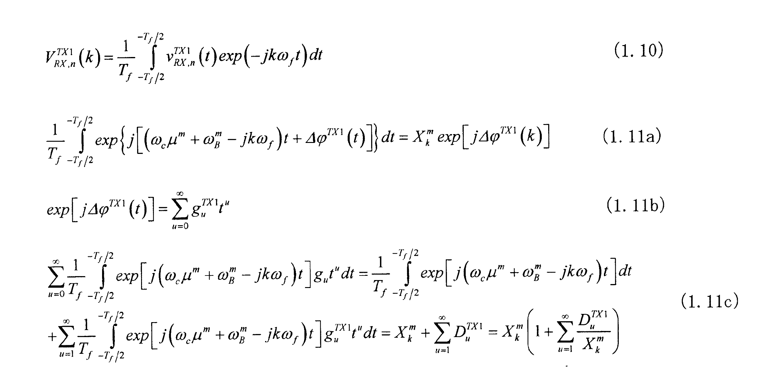
vTX1 RX,N(t)を例に取って具体的に示すと、周波数インデックスがk(k=−K/2
+1〜K/2)番目の要素は、以下の式(1.10)で与えられる。このため、m番目の目標に対するFFT結果は、空間位相を除いて式(1.11a)で表される。但し、式(1.11a)の左辺は、下記式(1.11b)のように定義した場合には、式(1.11c)等により得られる。なお、一般性を失わずg0 TX1=1とおいて良い。
v Specifically, taking TX1 RX, N (t) as an example, the frequency index is k (k = −K / 2).
The (+1 to K / 2) th elements are given by the following formula (1.10). For this reason, the FFT result for the mth target is expressed by Expression (1.11a) excluding the spatial phase. However, the left side of the formula (1.11a) is obtained by the formula (1.11c) or the like when defined as the following formula (1.11b). Note that g 0 TX1 = 1 may be set without losing generality.
最後に、信号処理部21では、位相誤差dψ(k)に基づく補正量exp[−jdψ(k)]をVTX2 RX,n(k)の全てのn及びkについて掛けることにより、VTX2 RX,n(k)の位相誤差をVTX1 RX,n(k)の位相誤差ΔψTX1(t)と合わせ、結果、開口合成を成立させていた。即ち、図7のレーダ装置の信号処理部21によって得られる開口合成信号は、下記式(1.14a)及び(1.14b)で示される(簡単の為、加法性雑音成分の影響は省略している)。
Finally, the
上述した比較例では、2個のアンテナを2つの測定時間帯でそれぞれ送信アンテナとして動作させ、N組の受信アンテナで被探知目標からのエコー信号を受信し、これらを空間位相が同じになる基準パスの位相長が等しいと考えて合成する。これによって、2N−1個のアンテナ素子からなる受信アレーアンテナを備えるレーダ装置(探知測距装置)を用
いて同時に信号を受信した様に機能させる(換言すれば、実効開口を拡大する)ことを可能とする。
In the comparative example described above, two antennas are operated as transmitting antennas in two measurement time zones, and echo signals from the detected target are received by N sets of receiving antennas. Combining them assuming that the path phase lengths are equal. As a result, a radar apparatus (detection and ranging apparatus) having a receiving array antenna composed of 2N-1 antenna elements is used to function as if signals were simultaneously received (in other words, the effective aperture is enlarged). Make it possible.
しかしながら、測定位置から同一距離を隔てて複数の被探知対象が存在し、各被探知目標が微少な速度差で運動しているシーン(例えば、レーダ装置を搭載した車両が渋滞に巻き込まれている状態)では、開口合成が上手く機能しない事があった。 However, a scene in which a plurality of detection targets exist at the same distance from the measurement position and each detection target moves with a slight speed difference (for example, a vehicle equipped with a radar device is involved in a traffic jam). State), aperture synthesis may not function properly.
図4は、シーン設定例を示す図である。以下、図4で示されるシーン設定を用いて、図1で示すレーダ装置の問題点を数式で検証する。図4のシーン設定では、2台の被探知目標T1、T2が、図1のレーダ装置Oから同距離(r1=r2=r)で角度θ1及びθ2の位置に存在し、それぞれ速度v1及びv2で運動している。 FIG. 4 is a diagram illustrating an example of scene setting. Hereinafter, the problem of the radar apparatus shown in FIG. 1 is verified by a mathematical expression using the scene setting shown in FIG. In the scene setting of FIG. 4, two detected targets T 1 and T 2 are present at the angles θ 1 and θ 2 at the same distance (r 1 = r 2 = r) from the radar apparatus O of FIG. Are moving at speeds v 1 and v 2 , respectively.
ここで、計算例で用いたレーダ装置の諸元について記しておくと、発振モジュール22から出力されるシステムリファレンス信号は、キャリア周波数が76ギガヘルツ[GHz](=ωC/2π)、RF−VCOへの変調入力信号(基準信号)の基本周期Tfが4[ms
ec]、片側変調帯域が50[MHz](=Δω/2π)のFMCW信号である。また、ア
ンテナ素子数Nが4、アンテナ素子間隔dが1.8λ(λはキャリア信号の波長)、サンプル数Kが512であるとした。更に、図4のシーン設定における各被探知目標の諸元(距離、角度、速度)をT1:(40[m]、0[deg]、10[km/h])、T2:(40[
m]、3(deg)、11(km/h))と、SNRを30[dB]と仮定した。なお、目
標諸元については、計算例毎に若干変更する事がある。
Here, the specifications of the radar apparatus used in the calculation example will be described. The system reference signal output from the
ec], an FMCW signal with a one-side modulation band of 50 [MHz] (= Δω / 2π). Further, the number N of antenna elements is 4, the distance d between antenna elements is 1.8λ (λ is the wavelength of the carrier signal), and the number K of samples is 512. Further, the specifications (distance, angle, speed) of each detected target in the scene setting of FIG. 4 are T 1 : (40 [m], 0 [deg], 10 [km / h]), T 2 : (40 [
m], 3 (deg), 11 (km / h)) and an SNR of 30 [dB]. The target specifications may be slightly changed for each calculation example.
このような各諸元を用いて、比較例に係るレーダ装置1において、先述の手順に従って開口合成操作を行い、周波数ドメインでの測角を行ったところ図5のような結果となった。図5は、比較例に係るレーダ装置1(図1)における測角結果を示すグラフである。図5に示す結果によれば、被探知目標の距離は概ね正確に推定できているものの、0度及び3度にそれぞれ1つずつ存在する被探知目標が1.5度付近に存在する1つの被探知目標として誤推定されている。
Using such specifications, the
そこで、このような誤推定の原因を特定するために、上記の合成信号(式(1.17))に逆フーリエ変換を施すことにより当該合成信号を時間ドメインの信号に再変換した後に、この再変換された時間ドメインの信号に測角アルゴリズムを適用した。図6は、図5で利用した周波数ドメインの信号から変換された、時間ドメインの信号に対する測角結果を示すグラフである。DBF、MUSIC及びPRISMの測角結果を示すグラフ(左上グラフ、右上グラフ、左下グラフ)によれば、本来、時間的に不変であるはずの目標角度(図では空間位相φTX1/2,m n(t)の傾きと記している)が時間に応じて変化している。 Therefore, in order to identify the cause of such erroneous estimation, this composite signal (formula (1.17)) is subjected to inverse Fourier transform to re-convert the composite signal into a time domain signal. An angle measurement algorithm is applied to the retransformed time domain signal. FIG. 6 is a graph showing the angle measurement result for the time domain signal converted from the frequency domain signal used in FIG. According to the graphs showing the angle measurement results of DBF, MUSIC, and PRISM (upper left graph, upper right graph, lower left graph), the target angle that should be essentially unchanged in time (in the figure, spatial phase φ TX1 / 2, m n (Slope of (t)) changes with time.
この例では、2つの被探知目標の相対速度差は1[km/h](≒0.28[m/sec])であるから、Tf(=4[msec])時間毎にこの速度差によって生じる被探知目標間
の距離差は約1.1[mm]に過ぎず、装置の距離分解能(≒0.75[m])と比べて遥かに小さな値である。言い替えれば、2つの測定時間を通して、各被探知目標の距離は同じとみなすことができるため、距離遅延によって定まる周波数ωB 1及びωB 2は、概ね同一の値ωBとなると考えて良い(式(2.1)参照。具体的には、周波数ωB 1及びωB 2は40[m]で概ね13[kHz]となる)。以上より、上記式(1.9a)及び(1.9b)は以
下の式(2.2a)及び(2.2b)のように書き換えることができる。
In this example, the relative speed difference between the two detection targets is 1 [km / h] (≈0.28 [m / sec]), so this speed difference is every T f (= 4 [msec]) time. The distance difference between detected targets caused by the above is only about 1.1 [mm], which is much smaller than the distance resolution of the device (≈0.75 [m]). In other words, since the distance of each detected target can be considered to be the same throughout the two measurement times, the frequencies ω B 1 and ω B 2 determined by the distance delay may be considered to be substantially the same value ω B ( (See Equation (2.1), specifically, the frequencies ω B 1 and ω B 2 are approximately 13 [kHz] at 40 [m]). From the above, the above equations (1.9a) and (1.9b) can be rewritten as the following equations (2.2a) and (2.2b).
)で表わすことができる。この式(2.3a)によれば、時間的に不変の空間位相(n−1)dsin(θm)が、時間に従って変化するドップラー位相推移2vmtと同程度のオーダーとなる(なお、ドップラー周波数は10[km/h]で1.4[kHz]程度である)。
). According to this equation (2.3a), the temporally invariant spatial phase (n−1) dsin (θ m ) is on the same order as the Doppler phase transition 2v m t that varies with time (note that The Doppler frequency is 10 [km / h] and about 1.4 [kHz]).
この結果、図6に示すように、時間ドメインにおいて角度推定を行った際に観察された現象(時間的に不変であるはずの角度が時間に応じて変化するかの如く振る舞う)が生じると考えられる。このような現象が上述のような問題点(図5で示されるような誤推定)を招いていると考えられる。 As a result, as shown in FIG. 6, it is considered that a phenomenon observed when angle estimation is performed in the time domain (behaves as if the angle that should be unchanged in time changes with time) occurs. It is done. Such a phenomenon is considered to cause the above-described problem (incorrect estimation as shown in FIG. 5).
のn及びtについて、この補正量を用いたexp[−jdψ(t)]を掛けることで、vTX2 RX,n(t)の位相誤差をvTX1 RX,n(t)の位相誤差と共通の位相誤差ΔψTX1(t)
に合わせた後、合成開口を行う。
Then, a synthetic aperture is made.
そこで、上記式(2.2a)及び(2.2b)を見直すと、距離遅延によって定まる周波数が13kHz程度であったのに対して、ドップラー周波数は1.4kHzと10分の1程度である。このため、式(2.2a)及び(2.2b)は、キャリア信号exp(jωBt)に総和記号内の時間変項で振幅変調が掛かっているものと見なせる(勿論、ここ
でいうキャリア信号とは周波数ωcのシステムキャリア信号ではない)。即ち、上記式(
2.2a)において、vTX1 RX,n(t)の総和項のみを取り出して整理すると、下記式(
2.5)のように示すことができる。
Therefore, when the above formulas (2.2a) and (2.2b) are reviewed, the frequency determined by the distance delay is about 13 kHz, whereas the Doppler frequency is about 1/10, which is 1.4 kHz. For this reason, the equations (2.2a) and (2.2b) can be considered that the carrier signal exp (jω B t) is subjected to amplitude modulation by the time variable in the summation symbol (of course, the carrier signal here) Is not a system carrier signal of frequency ω c ). That is, the above formula (
In 2.2a), if only the sum term of v TX1 RX, n (t) is extracted and arranged, the following formula (
2.5).
上述の擬似的な単一目標に由来する複素信号に先述のビート信号で振幅変調(AM)が掛かった信号が式(2.5)の実体である。これが、時間ドメインに於いて、位相補正から開口合成を行う事で、角度の時間変化は補正出来たにも拘らず、被探知目標の個数と角度の誤推定までは解決されなかった原因である。なお、元の被探知目標のドップラー信号間のビート信号(AM成分)は、式(2.5)(一般的には、式(1.9)や式(2.2))の包絡線として求められる事は明らかである。 A signal obtained by subjecting the complex signal derived from the above-described pseudo single target to amplitude modulation (AM) with the above-described beat signal is the substance of the equation (2.5). This is the reason why the number of detected targets and the incorrect estimation of the angle were not solved even though the time change of the angle could be corrected by performing aperture synthesis from phase correction in the time domain. . Note that the beat signal (AM component) between the original Doppler signals of the detection target is an envelope of Expression (2.5) (generally Expression (1.9) or Expression (2.2)). It is clear that it is required.
図8は、上記の結論の妥当性を検証する為、基準受信アンテナにおける復調信号とこの復調信号にヒルベルト(Hilbert)変換を施して得られた包絡線信号(AM成分)とを併
記したグラフである。各復調信号(式(2.2a)及び(2.2b))は上部に示され、各包絡線信号は下部に示されている。
FIG. 8 is a graph in which a demodulated signal at the reference receiving antenna and an envelope signal (AM component) obtained by performing a Hilbert transform on the demodulated signal are written together in order to verify the validity of the above conclusion. is there. Each demodulated signal (Equations (2.2a) and (2.2b)) is shown at the top and each envelope signal is shown at the bottom.
図8によれば、2つの測定時間[0、Tf]、[Tf、2Tf]で得られた受信信号の位
相が包絡線の影響によって大きく異なっていることが表されている。また、各包絡線信号の周波数(バイポーラ信号とみなした時)は、約73Hzであり、装置の最小周波数分解能である500Hzより遥かに小さい。このため、周波数ドメインで位相補正を施しても正確に開口合成ができないことが明らかである。
FIG. 8 shows that the phases of received signals obtained at two measurement times [0, T f ], [T f , 2T f ] are greatly different due to the influence of the envelope. The frequency of each envelope signal (when regarded as a bipolar signal) is about 73 Hz, which is much smaller than 500 Hz, which is the minimum frequency resolution of the apparatus. For this reason, it is clear that aperture synthesis cannot be performed accurately even if phase correction is performed in the frequency domain.
<第1実施形態>
以下、本発明の第1実施形態に係る探知測距装置について説明する。図9は、第1実施形態に係る探知測距装置の具体例であるレーダ装置の構成例を示す。図1に示した比較例と共通な構成要素には、同一の符号を付している。実施形態に係るレーダ装置として、プローブ信号にFMCW(Frequency Modulated Continuous Wave)を採用したレーダ装置
について説明する。レーダ装置は、車両のような移動体に搭載されることが想定されている。
<First Embodiment>
Hereinafter, the detection and ranging apparatus according to the first embodiment of the present invention will be described. FIG. 9 shows a configuration example of a radar apparatus which is a specific example of the detection and ranging apparatus according to the first embodiment. Constituent elements common to the comparative example shown in FIG. As a radar apparatus according to the embodiment, a radar apparatus that employs FMCW (Frequency Modulated Continuous Wave) as a probe signal will be described. The radar apparatus is assumed to be mounted on a moving body such as a vehicle.
図9において、レーダ装置1Aは、比較例と同様の構成を有するアレイアンテナ11、低雑音増幅器(LNA)12、電力増幅器(PWA)13、ミキサ(図9に示すMIX)14、A/D変換器15(一時的にデジタルデータを格納するメモリを実装する様に構成しても良い)、分岐器(ハイブリッド:HYB)16、包絡線検波部(HIL)17、積
分距離計算部(dist(τ))19、データクリッパ(Data Clipper)及び位相補正部(Phase Compensator)20、信号処理部(Data Processing Unit)21、発振モジュール22
、CPU(Central Processing Unit)23、スイッチコントローラ(SW Controller)24、スイッチ(SW)25、送信サイクル設定器(P/Q)26等を有する。これら各ユニットは、ソフトウェアの構成要素又はハードウェアの構成要素、若しくはこれらの組み合わせとしてそれぞれ実現される([その他]の項参照)。
In FIG. 9, a
, A CPU (Central Processing Unit) 23, a switch controller (SW Controller) 24, a switch (SW) 25, a transmission cycle setting device (P / Q) 26, and the like. Each of these units is realized as a software component, a hardware component, or a combination thereof (see [Others]).
発振モジュール22は、DDS(Direct Digital Synthesizer)等、ディジタル的に直接FMCW信号を生成可能な発振器を適用可能である。但し、図9には、一般的なアナログ式の回路構成、即ち、ベースバンド発振器(BB−OSC)と高周波電圧制御発振器(RF−VCO、勿論、電流制御型でも良い)とを組み合わせた発振モジュール22が図示されている。発振モジュール22では、BB−OSCから出力される基準信号がRF−VCOへ送られ、RF−VCOは基準信号によって周波数変調されたシステムリファレンス信号を出力する。基準信号には例えば三角波(図10)が利用される。
As the
PWA(HPA)13は、送信アンテナに対応する処理系統に設けられる。図9の例では、送信アンテナとして利用される2つの送信アンテナAT1及びAT2に対応して2つのPWA13(#1)及びPWA13(#2)が設けられている。PWA13は、発振モジュール22から出力されたシステムリファレンス信号を増幅する。PWA13から出力されるシステムリファレンス信号は、送信アンテナとして選択されている送信アンテナAT1及びAT2の一方から目標探知用のプローブ信号として出力される。
The PWA (HPA) 13 is provided in a processing system corresponding to the transmission antenna. In the example of FIG. 9, two PWA13 (# 1) and PWA13 (# 2) are provided corresponding to two transmission antennas A T1 and A T2 used as transmission antennas. The
アレイアンテナ11は、異なる空間位置にそれぞれ配列されたN個のアンテナ(センサ)素子を有する。例えば、アレイアンテナ11は、各アンテナ素子が直線上に等間隔で配列された等間隔リニアアレイアンテナ(ULA(Uniform Linear Array) antenna)を形成する。図9の例では、直線上に配列された各アンテナ素子のうち、両端の2つのアンテナ素子は、送信及び受信の双方に利用(共用)され、それ以外のアンテナ素子は受信専用で利用される。以降、送信及び受信に利用されるアンテナ素子を共用アンテナAR1/T1、
ARN/T2と表記することもある。
The
A Sometimes referred to as RN / T2 .
各共用アンテナ共用アンテナAR1/T1、ARN/T2は、スイッチ25により時分割で送信用又は受信用に切り替えられる。受信用アンテナとして動作するアンテナ素子はAR1からARNと表記され、送信用アンテナとして動作するアンテナ素子はAT1及びAT2と表記される。このように、レーダ装置1Aでは、複数の送信アンテナと複数の受信アンテナとを組み合わせて実効的な受信アンテナの数を拡大させる開口拡大技術が利用される。
The shared antennas A R1 / T1 and A RN / T2 are switched by the
スイッチ25は、スイッチコントローラ24からの制御信号に応じて、共用アンテナAR1/T1、ARN/T2の夫々を、送信状態と受信状態との間で切り替える。具体的には、共用アンテナAR1/T1は、スイッチ25(#1)によって、PWA13(#1)に接続される送
信状態と、LNA12(#1)に接続される受信状態との間で切り替わる。共用アンテナAR1/T1は、送信状態において送信アンテナAT1として動作し、受信状態において受信ア
ンテナAR1として動作する。同様に、共用アンテナARN/T2は、スイッチ25(#2)に
よって、PWA13(#2)に接続される送信状態と、LNA12(#N)に接続される受信状態との間で切り替わる。共用アンテナARN/T2は、送信状態において送信アンテナ
AT2として動作し、受信状態において受信アンテナARNとして動作する。
The
スイッチコントローラ24は、CPU23から送られて来る送信サイクル情報(P/Q)、及び発振モジュール22のベースバンド発振器から出力される基準信号の周期Tfに
応じて、スイッチ25の切り替えタイミングを制御する。
The
送信サイクル設定器26は、信号処理部21からの要求により基準信号の周期Tf又は
送信サイクル情報(P/Q)の変更指示をCPU23へ送る。送信サイクル情報(P/Q)とは、基準信号の周期Tfを一単位として(但し、個々の共用アンテナを1つのタイム
スロットの中で送受用途に切り替える際のデューティー比は無視)、送信アンテナAT1を利用するタイムスロットの比率(P)と送信アンテナAT2を利用するタイムスロットの比率(Q)とを示す。
The transmission
スイッチコントローラ24は、PTf(=P×Tf)の間、共用アンテナARN/T2を受信
アンテナARNとして用い、共用アンテナAR1/T1を所定の周期で切り替えながら送信アン
テナAT1及び受信アンテナAR1として利用する。また、スイッチコントローラ24は、QTf(=Q×Tf)の間、共用アンテナAR1/T1を受信アンテナAR1として用い、共用アン
テナARN/T2を所定の周期で切り替えながら送信アンテナAT2及び受信アンテナARNとし
て利用する。
The
図10は、送信サイクル情報(P=1、Q=2)を用いた場合の送受信タイミングを示すタイミングチャートである。時間は紙面の左から右に向かって流れている。図10に示す例では、時間[0、Tf]では、送信アンテナAT1は、所定の周期Tfにおいてプローブ信号を放射し、受信アンテナARNは継続的にエコー信号を受信する。測定時間[Tf、3
Tf]では、送信アンテナAT2は所定の時間区間(2Tf)に亘ってプローブ信号を放射し、受信アンテナAR1は継続的にエコー信号を受信する。
FIG. 10 is a timing chart showing transmission / reception timings when transmission cycle information (P = 1, Q = 2) is used. Time flows from left to right on the page. In the example shown in FIG. 10, at time [0, T f ], the transmitting antenna A T1 radiates a probe signal at a predetermined period T f , and the receiving antenna A RN continuously receives an echo signal. Measurement time [T f , 3
In T f ], the transmitting antenna A T2 emits a probe signal over a predetermined time interval (2T f ), and the receiving antenna A R1 continuously receives the echo signal.
図10のタイミングチャートを参照し、測定開始時刻を0として、本実施形態に基づく「装置としての動作の1周期」を示すと、タイムスロット[0、PTf]では共用アンテ
ナAR1/T1が共用アンテナとして動作する一方で、アンテナAR2〜ARNが受信アンテナと
して動作する。また、タイムスロット[PTf、(P+Q)Tf]では、アンテナARN/T2
が共用アンテナとして動作する一方で、アンテナAR1〜ARN-1が受信アンテナとして動作する。
Referring to the timing chart of FIG. 10, when the measurement start time is 0 and “one period of operation as an apparatus” based on the present embodiment is shown, the shared antenna A R1 / T1 is set in the time slot [0, PT f ]. While operating as a shared antenna, antennas A R2 to A RN operate as receiving antennas. In the time slot [PT f , (P + Q) T f ], the antenna A RN / T2
Operate as shared antennas, while antennas A R1 to A RN-1 operate as receiving antennas.
図9に戻って、LNA12は、受信アンテナに対応する処理系統に設けられる。図9の例では、LNA12(#2)からLNA12(#N−1)は各受信アンテナAR2からARN-1にそれぞれ常時接続される。LNA12(#1)は、スイッチ25(#1)の切り替えにより受信アンテナAR1に接続される。LNA12(#N)は、スイッチ25(#2)の切り替えにより受信アンテナARNに接続される。各LNA12は、接続される受信アンテナからエコー信号(受信信号)を受け、受信信号を増幅する。増幅された信号は、ミキサ14に送られる。
Returning to FIG. 9, the
ミキサ14(14(#1)〜(#N))は、LNA12に接続される。ミキサ14は、LNA12により増幅された信号を発振モジュール22から送られるシステムリファレンス信号と混合させることにより、受信信号をベースバンド信号に変換する。
The mixer 14 (14 (# 1) to (#N)) is connected to the
A/D変換器15は、ミキサ14から出力されるベースバンド信号を所定のサンプリング周波数でディジタルベースバンド信号に変換する。以降、このディジタルベースバンド信号を復調信号と表記することもある。
The A /
HYB16は、受信アンテナAR1及びARNで受信された信号の復調信号を処理するために、受信アンテナAR1及びARNに対応する各処理系統にそれぞれ設けられる。具体的には、HYB16(#1)はA/D変換器15(#1)に接続され、HYB16(#2)はA/D変換器15(#N)に接続される。 HYB16 to process the demodulated signals of the signals received by the receiving antennas A R1 and A RN, is provided in each processing system corresponding to the receiving antennas A R1 and A RN. Specifically, the HYB 16 (# 1) is connected to the A / D converter 15 (# 1), and the HYB 16 (# 2) is connected to the A / D converter 15 (#N).
言い換えれば、HYB16は、アレイアンテナ11に於いて空間位相が等しくなる送信
アンテナ及び受信アンテナの組み合わせにおける受信アンテナで受信された信号を処理する処理系統に設けられる。従って、HYBとHILとを実装する箇所を、図9に示すようなアレイアンテナの最外縁の受信アンテナに限定する必要はない。開口合成操作は、このように等しい空間位相を与える送信アンテナ及び受信アンテナの組み合わせで受信された信号を基準として実行される。以降、このように開口合成の基準として採用される送信アンテナ及び受信アンテナの組み合わせを基準組み合わせと表記し、基準組み合わせにおける送信アンテナ及び受信アンテナを基準送信アンテナ及び基準受信アンテナと表記する。
In other words, the
なお、第1実施形態では、基準送信アンテナAT1と基準受信アンテナARNの組み合わせと基準送信アンテナAT2と基準受信アンテナAR1との組み合わせが、最も開口拡大率の良い基準組み合わせとなる。基準組み合わせにおいて送受信される信号の経路は、“基準パス”と呼ばれる。具体的な他の基準組み合わせとしては、基準送信アンテナAT1と基準受信アンテナAR1の組み合わせと基準送信アンテナAT2と基準受信アンテナARNとの組み合わせ等が考えられる。この場合、基準とする位相長はゼロになる。なお、基準組み合わせという語と基準パスという語とを区別しないで用いる事がある。 In the first embodiment, the combination of the reference transmission antenna A T1 and the reference reception antenna A RN and the combination of the reference transmission antenna A T2 and the reference reception antenna A R1 are the reference combination having the best aperture expansion ratio. A path of signals transmitted and received in the reference combination is called a “reference path”. As other specific reference combinations, a combination of the reference transmission antenna A T1 and the reference reception antenna A R1 and a combination of the reference transmission antenna A T2 and the reference reception antenna A RN can be considered. In this case, the reference phase length is zero. Note that the term “reference combination” and the term “reference path” are sometimes used without distinction.
図10のタイミングチャートに従ってレーダ装置1Aを動作させた場合における開口合成が成立する条件は、図3で表すことができる。図3は、基準送信アンテナAT1からプローブ信号が放射され、そのエコー信号がタイムスロット[0、Tf](以降、測定時間A
とも表記する)に於いて基準受信アンテナARNで受信されている様子を示している。更に、図3は、基準送信アンテナAT2からプローブ信号が放射され、そのエコー信号がタイムスロット[Tf、3Tf](以降、測定時間Bとも表記する)に於いて基準受信アンテナAR1で受信されている様子も示している(但し、実際に図3に示してあるタイムスロットBは[Tf、2Tf]である)。
The conditions under which aperture synthesis is established when the
In this case, the signal is received by the reference receiving antenna ARN . Further, FIG. 3 shows that a probe signal is radiated from the reference transmission antenna A T2 , and the echo signal is transmitted from the reference reception antenna A R1 in the time slot [T f , 3T f ] (hereinafter also referred to as measurement time B). It also shows that it is being received (however, the time slot B actually shown in FIG. 3 is [T f , 2T f ]).
図3から明らかな様に、測定時間A及びBのそれぞれで受信された各信号に対して開口合成が成立するのは、測定時間Aに於いて基準受信アンテナARNで受信された信号と、測定時間Bに於いて基準受信アンテナAR1で受信された信号との位相長が一致する場合である。 As is apparent from FIG. 3, the aperture synthesis is established for each signal received at each of the measurement times A and B. The signal received at the reference reception antenna A RN at the measurement time A is This is a case where the phase length of the signal received by the reference receiving antenna A R1 coincides with the measurement time B.
HYB16は、A/D変換器15から出力される復調信号を包絡線検波部17方向とデータクリッパ/位相補正部20方向とに分岐する。包絡線検波部17は、基準受信アンテナで受信されたエコー信号の復調信号を処理するために各HYB16にそれぞれ接続される。包絡線検波部17は、HYB16から入力される復調信号の包絡線成分を検出する。以降、包絡線検波部17で取得した包絡線成分を包絡線信号と表記する場合もある。
The
包絡線検波部17は、例えば、信号処理部21で行われる高速フーリエ変換(FFT(Fast Fourier Transformation))の最小周波数分解能より長い周期(低い周波数)を持
つ信号成分の存在を検出した場合、取得された包絡線信号を積分距離計算部19に送る。なお、包絡線検波部17は、当該フーリエ変換の最小周波数分解能より長い周期を持つ包絡線成分の存在を検出した場合に限り、上述の送信サイクル情報(P及びQ)でのプローブ信号放射をCPU23に要求するように送信サイクル設定器26へ依頼するようにしてもよい(P、Q、及び、Tfの値を変更する事も含む)。なお、包絡線検波部17は、例
えば、ダイオード検波器、直交復調器、ヒルベルト変換器、ウェーブレット変換器、フィルタバンク等を利用して実現される。
The
第1実施形態では、包絡線検波部17には、ヒルベルト変換器が適用されている。ヒルベルト変換器は、複素信号の実数成分のみからなる信号(実際に測定される復調信号は全て実数である)に対するヒルベルト変換を行い、虚数成分を求める。これによって、複素信号(解析信号)が得られる。その後、ヒルベルト変換器は、実数成分の自乗と虚数成分
の自乗との和の平方根をとる。
In the first embodiment, a Hilbert transformer is applied to the
もし、ミキサ14、或いはA/D変換器15の出力がI/Q(同相/直交)成分に分離されているならば、包絡線は計算式“sqrt[I2(t)+Q2(t)]”(すなわち、I2(t)+Q2(t)の平方根)によって簡易に求めることができる。この場合、ヒルベルト変換の操作は不要となる。なお、得られた包絡線に対しては、適宜、雑音除去のための平滑処理が行われる。また、信号処理部21による開口合成時の位相補正では、unwrap処理が施される。
If the output of the
データクリッパ/位相補正部20のデータクリッパは、各タイムスロットに於いて各受信アンテナで受信された信号の復調信号を各A/D変換器15からそれぞれ受け、それぞれメモリに保持する(即ち、このメモリは上述した「装置としての動作の1周期」に得られるA/D変換器15からの出力をタイムスロット毎及び受信系(アンテナ〜A/D変換器)毎にアクセス可能な形で保存しておく事ができ、更に、後述の各操作に於いては所望のタイムスロットに於ける所望の受信系からのデータが、適切に出力する事ができるものとする)。
The data clipper of the data clipper /
データクリッパは、積分距離計算部19から送られた遅延量に基づいて、入力された各復調信号の包絡線成分の位相を合わせる。具体的には、データクリッパは、[Tf、3Tf]間の各復調信号から当該遅延量以降のTf時間分の信号をそれぞれ切り出す。これによ
り、[0、Tf]間の各復調信号と包絡線の位相が一致するデータを、[Tf、3Tf]間
の各復調信号から取得することができる(即ち、異なるタイムスロットに於いて取得したデータ列から、包絡線の位相が一致したデータ列を得られる)。データクリッパは、このように位相補正された各復調信号を位相補正部へ送る。
The data clipper matches the phase of the envelope component of each input demodulated signal based on the delay amount sent from the integral
データクリッパ/位相補正部20の位相補正部は、データクリッパから送られて来る包絡線成分の位相が揃った各復調信号を受け(なお、ここで用いた具体例に於いて、データクリッパから送られてくるデータの長さは、タイムスロット[0、Tf]のそれと同じで
ある)、これら各復調信号の残留位相誤差を補正する。具体的には、各回路素子の特性バラツキ等も含めてベースバンド信号に含まれる残留位相誤差の影響をキャンセルするために、式(2.4)を用いて(時間ドメインに於ける)補正量を算出し、この補正量に応じて、データクリッパで包絡線の位相が合う様に切り取られた測定時間[Tf、3Tf]における各復調信号の位相誤差を他の測定時間[0、Tf]での各復調信号の位相誤差にあわ
せるように補正する(但し、包絡線の位相を揃えたデータであれば、時間ドメインのデータにFFTを掛けて周波数ドメインのデータに変換し、式(1.13)式で補正量を算出し、周波数ドメインに於いて上述の様な補正処理を実施しても良い)。このように残留位相誤差の補正が行われた各信号は、信号処理部21へ送られる。
The phase correction unit of the data clipper /
信号処理部21は、データクリッパ/位相補正部20から送られる各信号を開口合成し、開口合成された信号にDBF(Digital Beam Forming)法、MUSIC(MUltiple SIgnal Classification)法、PRISM(PRopagator method based on an Improved Spacial-smoothing Matrix )法等のような既知の角度推定アルゴリズム(以降、単に測角アルゴリズムと表記する)を適用する。なお、時間ドメインで開口合成された信号をフーリエ変換(FFT(Fast Fourier Transformation))等により周波数ドメインの信号に変換
し、この周波数ドメインの信号に対して測角アルゴリズムを適用するようにしてもよい。開口合成手法及び測角アルゴリズムは周知の技術を用いればよいため、ここでは説明を省略する。なお、信号処理部21は、測角アルゴリズムにおいて、自己相関成分を含まない相関行列を用いるようにしてもよい。
The
また、信号処理部21は、包絡線検波部17から包絡線そのものの周波数、乃至、この
包絡線を構成する信号成分の個々の周波数の情報を取得し、所定の方法により包絡線成分(或いは、上記の各量)を取得するようにしてもよい。この場合、信号処理部21は、この周波数成分(或いは、上記の各量)が所定閾値より小さい場合には、送信サイクル設定器26から基準信号の周期Tfを変更する指令を出すようにしてもよい。
Further, the
ところで、比較例に関して明らかにした様に、同一距離に存在する複数の被測距目標が小さな速度差で運動している場合、ドップラー周波数の差分の周波数を持つ振幅変調(AM)成分が発生する。ドップラー周波数の差分の周波数が信号処理部(Signal Processing Unit)21で利用する第1の周波数分析部(例えばFFT)の解像度より小さい場合には、周波数ドメインに於ける位相補正法では開口合成が適正に行われない。時間ドメインで補正を行っても、十分な開口合成結果が得られないことがあった。 By the way, as clarified with respect to the comparative example, when a plurality of distance measurement targets existing at the same distance are moving with a small speed difference, an amplitude modulation (AM) component having a frequency difference of the Doppler frequency is generated. . When the frequency of the difference between the Doppler frequencies is smaller than the resolution of the first frequency analysis unit (for example, FFT) used in the signal processing unit (Signal Processing Unit) 21, aperture synthesis is appropriate in the phase correction method in the frequency domain. Not done. Even if correction is performed in the time domain, a sufficient aperture synthesis result may not be obtained.
そこで、第1実施形態では、基準パスの信号を包絡線検波部17によって監視する。監視において、第1の周波数分析部の最小周波数分解能より長い周期を持つ包絡線成分が存
在した場合には、TX1(送信アンテナAT1)からPTf時間、TX2(送信アンテナAT2)からQTf時間(P,Q∈Z)プローブ信号を放射する。
Therefore, in the first embodiment, the reference path signal is monitored by the
積分距離計算部19は、TX1及びTX2の夫々に対応する基準パスの包絡線位相が一致するまでのタイムラグを検出する。具体的には、積分距離計算部19は、パラメータτに関して積分距離dist(τ)を計算し、積分距離が最小となった際のパラメータτの値を以て包絡線位相が一致するまでのタイムラグが検出されたものとする。
The integration
そして、データクリッパ/位相補正部20におけるデータクリッパによって、TX1又はTX2(例えばTX1)の位相を基準として、上述のタイムラグからTX2のプローブ信号による各受信アンテナのデータ(復調信号)をTf時間分切り出し、基準パスの包絡
線成分も含めた復調信号について、位相補正部で位相補正が行われる。
Then, the data clipper in the data clipper /
上記した積分距離計算部19、データクリッパ/位相補正部20による操作でも適正な開口合成結果が得られない程度にドップラー周波数の差分周波数が小さい場合には、プローブ信号の送信サイクル設定器(P/Q)26からRF−VCOへの変調入力信号の周期Tf自体を変更する指令(制御命令)が出力される。制御命令は、例えばCPU23から送信サイクル設定器26へ出力することができる。但し、制御命令の出力ソースはCPU23に限られず、データクリッパ/位相補正部20や信号処理部21、或いは他の制御装置から出力することができる。また、図9の例では、データクリッパと位相補正部とが同一のブロックで表されているが、これらは異なるハードウェアチップで実現されることができる。
If the difference frequency of the Doppler frequency is so small that an appropriate aperture synthesis result cannot be obtained even by the operations of the integration
或いは、P及びQの少なくとも一方の値を大きくする制御信号が出力されるようにしても良い。P及びQの少なくとも一方を大きくする程度は、最小差分周波数の逆数に比例した観測時間が要求される。このため、具体的な値は、レーダ装置1Aを搭載した車両(移動体)の走行環境に応じて設定される。P,Qの値は、特に、料金所や交差点等の渋滞箇所では非常に大きくなると考えられる。制御命令の出力トリガは、レーダ装置1Aのユーザによるマニュアル操作、或いは、車両(移動体)に搭載された走行環境を検知するセンサ(例えば、レーダを搭載する車体に装備された速度計で検出される移動速度、GPSやDSRC等のインフラベースの環境情報提供装置)に応じて発せられるようにすることができる。
Alternatively, a control signal that increases at least one of P and Q may be output. The degree of increasing at least one of P and Q requires an observation time proportional to the reciprocal of the minimum differential frequency. For this reason, a specific value is set according to the traveling environment of the vehicle (moving body) on which the
図11は、探知目標数を3とし、各目標T1,T2,T3の諸元が、T1(40[m]、0[deg]、10[km/h])、T2(40[m]、3[deg]、11[km/h])、T3:(40[m]、6[deg]
、12[km/h])、信号対雑音比(SNR)=30[dB]である場合において、図9のレーダ
装置1Aを図10のタイミングチャートに従って動作させたときの各基準パスのエコー信号とその包絡線を示す。図11中の左側に、送信アンテナTX1に対する基準パスのエコー信号(復調信号)(上段)及び包絡線(下段)を示し、図11中の右側に送信アンテナTX2に対する基準パスのエコー信号(復調信号)(上段)及び包絡線(下段)を示す。図11の例では、計算の簡易化のため、TX1に対する基準パスのエコー信号にゼロパディングを行い、TX2に対する基準パスのエコー信号のデータ長を一致させている。
In FIG. 11, the number of detection targets is 3, and the specifications of each target T 1 , T 2 , T 3 are T 1 (40 [m], 0 [deg], 10 [km / h]), T 2 ( 40 [m], 3 [deg], 11 [km / h]), T 3 : (40 [m], 6 [deg]
12 [km / h]) and the signal-to-noise ratio (SNR) = 30 [dB], the echo signal of each reference path when the
図12は、図11に示した包絡線の位相が一致するタイムラグを、基準パスの復調信号の包絡線vTX1,env RX,N(t)、vTX2,env RX,1(t)の積分距離の最小値から計算した例である(但し、以降の積分距離の計算例では、見易くする為、平均操作を行う前の値で示している)。積分距離dist(τ)は次式(3.1a)で与えられる。dist(τ)の計算は、図9に示した積分距離計算部19で実行される。なお、メモリの節約等を目的として利用するタイムスロットを[0、Tf]の1区間分に限定したい場合は、式(3.1b)を式(3.1b)の代わりに利用しても良い。
FIG. 12 shows the integration of the envelopes v TX1, env RX, N (t), v TX2, env RX, 1 (t) of the demodulated signal of the reference path with the time lag in which the envelope phases shown in FIG. This is an example calculated from the minimum value of the distance (however, in the following calculation examples of the integrated distance, the values before the averaging operation are shown for easy viewing). The integral distance dist (τ) is given by the following equation (3.1a). The calculation of dist (τ) is executed by the integral
)、vTX2,env RX,1(t)の存在する時間区間を合わせる操作(PTf、乃至、QTfの加
算/減算)、或いは、平均操作等(積分区間の幅での除算)等 ― は、装置上で式(3.1a)をどの様に実装するかによって適宜決めれば良い。この意味でP≠Qなる場合、不足するデータ分をゼロパディングによって補えば、積分距離の演算自体は、一般的な関数間で積分距離を求める単一の式で事足りる。
), V TX2, env RX, 1 An operation for adjusting the time interval in which (t) exists (addition / subtraction of PTf or QTf), an average operation or the like (division by the width of the integration interval), etc. What is necessary is just to determine suitably according to how Formula (3.1a) is mounted on an apparatus. In this sense, if P ≠ Q, if the missing data is compensated by zero padding, the calculation of the integration distance itself is sufficient by a single expression for obtaining the integration distance between general functions.
図13は、図12で検出されたタイムラグ(Lag)に基づいて、図11に示した信号vTX2 RX,1(t)の全区間に渡るデータ(復調信号及び包絡線)から、Lag+[0、Tf]に該当する区間を切り出したグラフ(右側)と、[0、Tf]に於ける復調信号vTX1 RX,N
(t)及び包絡線のグラフ(左側)とを示す。図13に示すように、包絡線の位相が揃っ
たデータ(信号)が得られている。このような位相を揃える操作は、図9に示したデータクリッパ/位相補正部20におけるデータクリッパによって実行される。
13 is based on the time lag (Lag) detected in FIG. 12, and the data (demodulated signal and envelope) over the entire section of the signal v TX2 RX, 1 (t) shown in FIG. , T f ], a graph (right side) cut out, and the demodulated signal v TX1 RX, N at [0, T f ]
(T) and an envelope graph (left side) are shown. As shown in FIG. 13, data (signal) in which the phases of the envelopes are aligned is obtained. Such an operation of aligning the phases is executed by the data clipper in the data clipper /
図14は、図13に示した基準パスの信号を用い、復調信号vTX2 RX、n(t)に対して図9のデータクリッパ/位相補正部20における位相補正部で位相補正を行い、信号処理部21において開口合成を行い、合成された信号にFFTを施し、周波数ドメインで測角を実施した結果を示す。位相補正は、上記した式(2.4)に基づいて実行される。図14に示すように、既存の超分解測角手法であるMUSICやPRISMと、上記したような基準パス信号の包絡線の位相が一致するタイムラグを用いた位相補正手法との組合せによって、好適
な推定が実現されていることが分かる。
14 uses the reference path signal shown in FIG. 13 and performs phase correction on the demodulated signal v TX2 RX , n (t) by the phase correction unit in the data clipper /
上述した位相補正手法を適用した別の計算例を図15〜18に示す。別の計算例では、各目標諸元がT1(40[m]、0[deg]、10[km/h])、T2(40[m]、3[deg]、10.1[km/h])、T3(40[m]、6[deg]、11[km/h])、SNR=30[dB]である。また、レ
ーダ装置1AにおけるP,Qの値がP=1,Q=30に設定されている。さらに、レーダ装置1Aは、図10に示したタイミングチャートに従って動作した。
Another calculation example to which the above-described phase correction method is applied is shown in FIGS. In another calculation example, each target specification is T 1 (40 [m], 0 [deg], 10 [km / h]), T 2 (40 [m], 3 [deg], 10.1 [km]. / h]), T 3 (40 [m], 6 [deg], 11 [km / h]), SNR = 30 [dB]. Further, the values of P and Q in the
相対速度差の最小値が僅か0.1[km/h]=0.028[m/sec]、即ち、周期Tf毎に生じる目標の距離差が僅か0.11[mm]という微少摂動に対しても、レーダ装置1Aにおける位相補正方法の有効性が示された。因みにこの距離変動は、直接スペクトラム拡散型のレーダを用いても検出困難である(具体的には、占有帯域が1GHz程度で10cmの距離差しか検出できない)。この事実は、超広帯域探知測距装置でも困難な微少距離の測定が実施形態のレーダ装置によって実現されている事をも表している。
The minimum value of the relative speed difference is only 0.1 [km / h] = 0.028 [m / sec], that is, the target distance difference generated every period T f is only 0.11 [mm]. In contrast, the effectiveness of the phase correction method in the
上記の位相補正手法は、複数の距離に相対速度が近接した複数の被探知目標が存在する場合でも対応可能である。以下にその理由を示す。例えば、距離r1に目標T1(r1、θ1、v1)、目標T2(r1、θ2、v2)が存在し、距離r2に目標T3(r2、θ3、v3)、目標T4(r2、θ4、v4)が存在する場合を考える。 The above-described phase correction method can be used even when there are a plurality of detected targets whose relative velocities are close to a plurality of distances. The reason is shown below. For example, the target T 1 at a distance r 1 (r 1, θ 1 , v 1), the target T 2 (r 1, θ 2 , v 2) is present, the target T 3 at a distance r 2 (r 2, θ 3 , V 3 ) and target T 4 (r 2 , θ 4 , v 4 ) are present.
このとき、目標T1,T2の距離r1によって定まる周波数はωB 1≒ωB 2=ωB 1と定義で
きる。また、目標T3,T4の距離r2によって定まる周波数はωB 3≒ωB 4=ωB 3、と定義
できる。このため、各目標の角度によって定まる空間位相をφTX1/2,m n、速度によって定まるドップラー周波数をωcμm(m=1〜4)と定義すれば、TX1からのプローブ信号をn番目の受信アンテナで受信して得られるベースバンド信号は以下の式(3.2)で表すことができる(簡単の為、片側のTXだけについて示す)。
At this time, the target T 1, frequency determined by the distance r 1 of T 2 are ω B 1 ≒ ω B 2 = ω
図19は、上記の数学的説明を模式的に示した図で、或るタイムスロットでTX1からプローブ信号を送信して得られた目標からのエコー信号の等位相面と、別のタイムスロットでTX2からプローブ信号を送信して得られた目標からのエコー信号の等位相面との関係を、基準パスとの関係で示している。 FIG. 19 is a diagram schematically showing the above mathematical explanation. In the equiphase surface of the echo signal from the target obtained by transmitting the probe signal from TX1 in a certain time slot, and in another time slot. The relationship with the equiphase plane of the echo signal from the target obtained by transmitting the probe signal from TX2 is shown by the relationship with the reference path.
この様に、2つのタイムスロットに於けるエコー信号の等位相面は合成包絡線をそれぞれの半径(図16からも明らかな様に、一般的に各合成包絡線の極座標上に於ける軌跡は単純な円や楕円とはならないが、目標数や諸元等が急激に変化しない限り、異なるタイムスロット間で測定した基準パスの位相が揃う時間帯が必ず存在する ― この前提が崩れた場合、空間平均を含む角度推定の前処理等も全て無効になる)として位相関係が時間に沿って回転していると考える事ができる。即ち、この2つの等位相面を合成するには、2つの発想がある。第1には、基準パスの信号の内積が最大となる遅延時間を探すことであり、第2には、基準パスの信号の差分が最小になる遅延時間を探す事である。第1実施形態における位相補正方法では、後者の発想を採用している。 In this way, the equiphase planes of the echo signals in the two time slots have their composite envelopes with their respective radii (as is clear from FIG. 16, generally, the locus on the polar coordinates of each composite envelope is Although it is not a simple circle or ellipse, there will always be a time zone in which the phase of the reference path measured between different time slots is aligned unless the target number, specifications, etc. change abruptly. It can be considered that the phase relationship rotates along with time as all the pre-processing of angle estimation including the spatial average becomes invalid. That is, there are two ideas for synthesizing these two equiphase surfaces. The first is to search for a delay time that maximizes the inner product of the reference path signals, and the second is to search for a delay time that minimizes the difference between the reference path signals. The latter idea is employed in the phase correction method in the first embodiment.
後者の発想では、積分距離を与える式(3.1a)に於いて、基準パスの信号vTX1,env RX,N(t)、vTX2,env RX,1(t)は異なるタイムスロットに於いて取得されたものであるから、信号の位相が一致した後に残留する成分は各々相関の無い雑音成分となる。即ち、基
準パスの位相が一致した時の積分距離は雑音電力と等しくなる。従って、基準パスの位相合成を判定する閾値として、積分距離が無信号時の雑音電力と概ね等しいか否かといった定量的な基準を採用することができる。
In the latter idea, in the equation (3.1a) giving the integral distance, the signals v TX1, env RX, N (t) and v TX2, env RX, 1 (t) of the reference path are in different time slots. Therefore, the components remaining after the signal phases coincide with each other are uncorrelated noise components. That is, the integration distance when the phase of the reference path matches is equal to the noise power. Therefore, a quantitative criterion such as whether or not the integration distance is approximately equal to the noise power at the time of no signal can be adopted as a threshold for determining the phase synthesis of the reference path.
図20は、別の計算例で示したような状況に於いて成立することを実証する計算例である。条件は、距離40mに目標T1(0[deg]、10[km/h])、T2(3[deg]、11[km/h])が存在し、距離60mに目標T3(−3[deg]、12[km/h])、T4(−6[deg]、13[km/h])が存在していると仮定している。図20によれば、明らかに、4つの目標に対して開口合成が成立していることが分かる。 FIG. 20 is a calculation example demonstrating that it is established in a situation as shown in another calculation example. Conditions include target T 1 (0 [deg], 10 [km / h]) and T 2 (3 [deg], 11 [km / h]) at a distance of 40 m, and target T 3 (−) at a distance of 60 m. 3 [deg], 12 [km / h]), T 4 (−6 [deg], 13 [km / h]) is assumed to exist. FIG. 20 clearly shows that aperture synthesis is established for four targets.
第1実施形態によるレーダ装置1Aによれば、TX1とTX2とに対応する基準パスの包絡線情報から、各測定時間に於いて開口合成が成立するデータ(信号)の位相を揃えることで、任意の状況に於いて実効的な受信センサの個数を増加させ、小型で多くのセンサを備えた探知測距装置を実現することができる。従って、実際の受信センサ数で分離可能な数より多くの目標に対して、精度の良い角度推定性能を発揮できる。
According to the
また、第1実施形態によるレーダ装置1Aによれば、単純な回路で開口合成を確立することが可能である。もっとも、レーダ装置の応答速度を向上させる為には、周波数毎に処理するのが望ましい。
Further, according to the
<第2実施形態>
図21は、本発明の第2実施形態に係る探知測距装置(レーダ装置1B)を示す図である。第2実施形態は、第1実施形態に係るレーダ装置1A(図9)と共通点を有するので、主として相違点について説明し、共通点については説明を省略する。
Second Embodiment
FIG. 21 is a diagram showing a detection and ranging apparatus (
レーダ装置1Bがレーダ装置1Aと大きく異なる箇所は、以下の点である。(1)少なくとも1つの基準パスの包絡線検波部17(図21では17(#2))の手前に、分岐器(HYB)30が配置され、第2の周波数分析部として配置された周波数分析部(f_analyzer)31と接続されている。(2)各受信アンテナに対応するベースバンド信号径路上に、中心周波数が可変のBPF(Band Pass Filter)32が設置されている。具体的には、各BPF32は、A/D変換器15とHYB16との間、又はA/D変換器15とデータクリッパ/位相補正部20との間に配置されている。
The places where the
レーダ装置1Bでは、周波数分析部31が基準パスの受信信号の復調信号(図22では、受信アンテナARNの復調信号)に対するフーリエ変換を行い、ベースバンド信号(復調信号)を構成する周波数を分析し、分析結果に基づいてN個の受信アンテナに対応するBPF32の中心周波数を制御する。包絡線検波部17は、BPF32によって帯域分割された各基準パスの受信信号(復調信号)に包絡線検波を施す。積分距離計算部19は、包絡線間の積分距離を求め、最小の距離値を与える遅延量(τ)から帯域毎の基準パス間の位相補正量を求める。データクリッパ/位相補正部20は、位相補正量を用いて包絡線も含めた当該帯域内の信号の全ての受信信号の位相を揃え、信号処理部21での開口合成機能を実現する。
In the
なお、BPF32の処理系列がN個の受信アンテナ毎に1つである場合には、上記した遅延量(τ)を求め、開口合成を行う操作を分割された帯域分だけ繰り返すことが要求される。よって、周波数分析部31及び中心周波数可変BPF32との組み合わせは、フィルタバンクで代用することができる。
When the processing sequence of
<第3実施形態>
図22は、本発明の第3実施形態に係る探知測距装置(レーダ装置1C)を示す図であ
る。第3実施形態は、第1、第2実施形態に係るレーダ装置1A(図9)と共通点を有するので、主として相違点について説明し、共通点については説明を省略する。
<Third Embodiment>
FIG. 22 is a diagram showing a detection and ranging apparatus (
レーダ装置1Cがレーダ装置1A(図9)と大きく異なる箇所は、以下の通りである。(1)レーダ装置1Bと同様に、少なくとも1つの基準パスの包絡線検波部17(図22では17(#2))の手前に、分岐器(HYB)30が配置され、第2の周波数分析部である周波数分析部(f_analyzer)31Aと接続されている。(2)個々の基準パスの信号をLPF(Low Pass Filter)32かスルーラインかを介して、HYB16及び包絡線検
波部17に通す経路が設置されている。
The places where the
レーダ装置1Cの動作は、以下の通りである。すなわち、周波数分析部31Aによって、基準パスの受信信号の復調信号(図22では、受信アンテナARNの復調信号)の周波数成分を分析する。周波数分析結果が、復調信号(ベースバンド信号)から距離及び速度を求めるための信号処理部21に含まれる第1の周波数分析部の最小分解能以下の周波数成分を含んでいた場合には、周波数分析部31Aは、LPF33及びスルーラインの両端に設けられたスイッチを制御して、基準パスの復調信号がLPF33に入力される状態にする。なお、対象の周波数成分を含まない場合には、周波数分析部31Aは、復調信号がスルーラインを通過する状態とする。
The operation of the
LPF32又はスルーラインを通過した基準パスの復調信号に対する以降の処理は、第1実施形態と同様である。各LPF33の遮断周波数は、第1の周波数分析部の最小分解能以下の周波数が設定される。周波数分析部31が第1の周波数分析部の最小分解能以下
の信号成分を検出しなかった場合には、周波数分析部31は、各基準パスの信号を、LPF33を介さず、そのまま包絡線検波器17に送出する。このように、周波数分析部31Aは信号径路のスイッチング動作を制御する。従って、本実施形態に於いて信号がスルーライン側から供給された場合、開口合成は包絡線を用いた時間領域で実施しても、比較例と同様にフーリエ変換を用いた周波数領域で実施しても良い。
The subsequent processing for the demodulated signal of the reference path that has passed through the
<第4実施形態>
次に、本発明の第4実施形態に係る探知測距装置(レーダ装置1D)について説明する。第4実施形態は、第1実施形態に係るレーダ装置1A(図9)と共通点を有するので、主として相違点について説明し、共通点については説明を省略する。
<Fourth embodiment>
Next, a detection and ranging apparatus (
第1〜第3実施形態では、図面をコンパクトにする為、アレーアンテナの最外縁に送信/受信共用アンテナ(センサ)を1つずつ配置し、両者に挟まれた空間に受信専用アンテナ(センサ)を配置した構成を装置の具体例として用いてきた。もっとも、送信/受信用(或いは送受共用)センサ(アンテナ)の数は適宜設定可能である。また、送信用センサの配置も、受信用センサ(受信アンテナ)と共用にする必要は無く、お互いに空間的に異なる位置に設置可能である。 In the first to third embodiments, in order to make the drawing compact, one antenna for transmission / reception (sensor) is arranged on the outermost edge of the array antenna one by one, and a reception-only antenna (sensor) in a space sandwiched between the two. A configuration in which is arranged has been used as a specific example of the apparatus. However, the number of transmission / reception (or transmission / reception) sensors (antennas) can be set as appropriate. Further, the arrangement of the transmission sensor does not need to be shared with the reception sensor (reception antenna), and can be installed at positions spatially different from each other.
図23は、第4実施形態に係る探知測距装置(レーダ装置1D)の構成例を示す図であり、図24は、図23のレーダ装置1Dのタイミングチャートである。図23に示すレーダ装置1Dは、レーダ装置1A(図9)における共用アンテナの代わりに、送信専用の送信アンテナAT1,AT2と、受信専用の受信アンテナAR1からARNが設けられている。
FIG. 23 is a diagram illustrating a configuration example of a detection and ranging apparatus (
すなわち、レーダ装置1Dは、受信のためにのみ利用される受信アンテナAR1からARNと、送信のためにのみ利用される送信アンテナAT1及びAT2と、を含むアレイアンテナ11Aを持つ。
That is, the
送信アンテナAT1,AT2には、PWA13が夫々接続されており、各PWA13の入力
端の一方には、スイッチ25Aを介してOSCモジュール22からのシステムリファレンス信号が入力されるようになっている。スイッチ25Aの切替制御は、スイッチコントローラ24によって実行される。送信/受信共用アンテナの代わりに、専用の送信アンテナを設けた事で、装置寸法という面では不利になるが、受信信号利得という面では性能向上が期待できる(図24参照)。
A
第4実施形態では、各受信アンテナの間隔をdに設定した場合、各送信アンテナの間隔は(N−1)×dに設定する。これにより、例えば、送信アンテナAT1と受信アンテナAR1との組み合わせと、送信アンテナAT2と受信アンテナARNとの組み合わせが基準組み合わせとなる。 In 4th Embodiment, when the space | interval of each receiving antenna is set to d, the space | interval of each transmitting antenna is set to (N-1) xd. Thereby, for example, the combination of the transmission antenna A T1 and the reception antenna A R1 and the combination of the transmission antenna A T2 and the reception antenna A RN are the reference combinations.
このように、送信アンテナは、受信アンテナと空間的に別の位置に設置可能である。更に、センサ間隔(アンテナ間の間隔。図23中の距離d)が等間隔であることは要求されない。以上の点を除き、第4実施形態は第1実施形態と同様の作用効果を奏する。なお、第4実施形態に係るアンテナアレイ11Aに係る構成は、第2、第3実施形態に適用してもよい。
In this way, the transmission antenna can be installed at a position spatially different from the reception antenna. Furthermore, the sensor interval (interval between antennas; distance d in FIG. 23) is not required to be equal. Except for the above points, the fourth embodiment has the same operational effects as the first embodiment. Note that the configuration of the
<変形例>
第1〜第4の実施形態で説明したように、実施形態に係るレーダ装置は、包絡線検波部17で基準パスの包絡線の位相を監視し、最小の包絡線の積分距離を積分距離計算部19で求めて如何なる目標に対しても開口合成が破綻しない様な補正を行う。
<Modification>
As described in the first to fourth embodiments, in the radar apparatus according to the embodiment, the
したがって、包絡線の周波数がフーリエ変換を用いて検知できる程十分高い場合には、第1〜第4実施形態におけるレーダ装置1A〜1Dに於ける補正手法を比較例(図1)で採用していた補正手法に切り替えるようにしてもよい(包絡線の周波数が高い場合には、例えば、レーダ装置1Aでは、積分距離計算部19から概ね同じ大きさを持つローカルマキシマム(或いは、ローカルミニマム)が何度も周期的に出現するので簡単に判定することができる。
Therefore, when the frequency of the envelope is high enough to be detected using Fourier transform, the correction method in the
これ以外に合成を行う上で注意の必要な状況は、(3.2)式に空間位相項を組み込んだ
次式(4.1)から判明する様に、空間位相とドップラー成分による位相とが等しくなってしまった場合であり、この時には、サンプリング周波数を変更する、不等間隔サンプリングを行う、被探知目標が正常に検出されていた時点に得られた目標諸元の値からカルマンフィルタ等の手段で予測される値を用いる、測定時間を所定時間ずらす、或いは、開口合成を行わないで測角を行う等、動作モードを切り替えるようにしてもよい。
In addition to this, the situation that requires attention in synthesis is the same as the phase due to the Doppler component, as can be seen from the following equation (4.1) in which the spatial phase term is incorporated into the equation (3.2). In this case, the sampling frequency is changed, the sampling is performed at irregular intervals, and the target specification value obtained when the detected target is normally detected is predicted by means such as a Kalman filter. The operation mode may be switched by using a measured value, shifting the measurement time by a predetermined time, or performing angle measurement without performing aperture synthesis.
但し、各信号に包絡線検波を施して得られる信号とは、|HIL(vTX1/2 RX、n(t))|で
あるから、角度スペクトラムがピークを示す目標の角度は実際の値と符号が反転している事に注意する必要がある(言い替えれば、各信号に包絡線検波を施して得られる信号は、100%変調に近い為、信号の絶対値に対して角度推定を行うこと、或いは、時間ダイバーシティによって開口合成を実現していることになる)。
However, since the signal obtained by applying envelope detection to each signal is | HIL (v TX1 / 2 RX , n (t)) |, the target angle at which the angle spectrum shows a peak is the actual value. It is necessary to note that the sign is inverted (in other words, the signal obtained by performing envelope detection on each signal is close to 100% modulation, so angle estimation is performed on the absolute value of the signal. Or, aperture synthesis is realized by time diversity).
[その他]
〈ハードウェアの構成要素(Component)及びソフトウェアの構成要素(Component)について〉
ハードウェアの構成要素とは、ハードウェア回路であり、例えば、フィールド・プログラマブル・ゲートアレイ(FPGA)、特定用途向け集積回路(ASIC)、ゲートアレイ、論理ゲートの組み合わせ、信号処理回路、アナログ回路等がある。
[Others]
<About hardware components (Component) and software components (Component)>
A hardware component is a hardware circuit, for example, a field programmable gate array (FPGA), an application specific integrated circuit (ASIC), a gate array, a combination of logic gates, a signal processing circuit, an analog circuit, etc. There is.
ソフトウェアの構成要素とは、ソフトウェアとして上記処理を実現する部品(断片)であり、そのソフトウェアを実現する言語、開発環境等を限定する概念ではない。ソフトウェアの構成要素としては、例えば、タスク、プロセス、スレッド、ドライバ、ファームウェア、データベース、テーブル、関数、プロシジャ、サブルーチン、プログラムコードの所定の部分、データ構造、配列、変数、パラメータ等がある。これらソフトウェアの構成要素は、コンピュータ内において、1又は複数のメモリ上で実現されるか、或いは、1又は複数のメモリ上のデータが1又は複数のプロセッサ(例えば、CPU(Central Processing Unit)、DSP(Digital Signal Processor)等)で実行されることにより実現さ
れる。
A software component is a component (fragment) that realizes the above processing as software, and is not a concept that limits a language, a development environment, or the like that realizes the software. Examples of software components include tasks, processes, threads, drivers, firmware, databases, tables, functions, procedures, subroutines, predetermined portions of program code, data structures, arrays, variables, parameters, and the like. These software components are realized in one or more memories in a computer, or data in one or more memories is one or more processors (for example, a CPU (Central Processing Unit), DSP, etc. (Digital Signal Processor) or the like).
なお、上述の各実施形態は、上記各処理部の実現手法を限定するものではない。上記各処理部は、上記ハードウェアの構成要素又はソフトウェアの構成要素若しくはこれらの組み合わせとして、本技術分野の通常の技術者において実現可能な手法により構成されていればよい。 In addition, each above-mentioned embodiment does not limit the realization method of each said process part. Each processing unit may be configured as a hardware component, a software component, or a combination thereof by a method that can be realized by a normal engineer in this technical field.
上述した第1から第4の実施形態は、以下の態様を含むことができる。 The first to fourth embodiments described above can include the following aspects.
《態様1》
U個のセンサ素子から構成される送信用センサアレイと、N個のセンサ素子から構成される受信用センサアレイとを利用し(送信センサと受信センサとは共用でも良い、以下同様)、各送信センサから放射されたプローブ信号が被探知目標によって反射される事で生じるエコー信号(以下、受信信号)を各受信センサで測定し、空間位相が等しくなる送/受信センサの組み合わせで構成される基準パスの位相を用いて開口合成を行い、合成された信号から目標の角度を推定する装置、特に探知測距装置Aにおいて、
各基準パスで得られる受信信号に包絡線検波を施し、それらの積分距離を求め、最小の距離値を与える遅延量から基準パス間の位相補正量を求め、この補正量を用いて包絡線も含めて全ての受信信号の位相を揃え、目標の状況と無関係に開口合成機能を実現する事を特徴とする装置、及び手法。
<<
Each transmission is performed using a transmission sensor array composed of U sensor elements and a reception sensor array composed of N sensor elements (the transmission sensor and the reception sensor may be shared, and so on). A reference composed of a combination of transmitter / receiver sensors that measure the echo signals (hereinafter referred to as received signals) generated by reflection of the probe signal radiated from the sensor by the target to be detected by each receiving sensor and the spatial phase becomes equal. In an apparatus that performs aperture synthesis using the phase of a path and estimates a target angle from the synthesized signal, particularly in the detection and ranging apparatus A,
Envelope detection is performed on the received signals obtained in each reference path, their integration distance is obtained, the phase correction amount between the reference paths is obtained from the delay amount that gives the minimum distance value, and the envelope is also calculated using this correction amount. An apparatus and method characterized by aligning the phases of all received signals including the above and realizing the aperture synthesis function regardless of the target situation.
《態様2》
態様1における探知測距装置Aにおいて、装置の変調方式の基本周期、例えば、FMCW装置ではRF-VCOへの変調入力信号の周期:Tfに対し、u番目の送信センサからQuTf時間ずつ
プローブ信号を放射し(Qu∈Z、u=1〜U)、N個の受信用センサは送信時間に対応する時間の信号を受信して各基準パスの信号を包絡線検波し、必要性があれば、max(QuTf)に満
たない受信信号については不足分をゼロパディングして全ての受信信号のデータ長を合わせた上で、基準パスの包絡線の積分距離を求め、最小の距離値を与える遅延量からカウン
トしてmin(QuTf)時間分の信号を切り出す事で包絡線も含めて全ての受信信号の位相を
揃え、目標の状況と無関係に開口合成を実現する事を特徴とする装置、及び手法(特に、min(QuTf)としてTfを採用しても良い)。
<<
In the detection and ranging apparatus A according to the
なお、遅延量に沿って積分距離を求めていった結果、複数の箇所に最小値に極めて近いローカルミニマムが現れる場合もあり得るが、この場合、最も小さな遅延量に対応するローカルミニマムを信号切り出しの基準点として採用する。実用的には最小値はノイズレベル程度になるので、無信号時の雑音レベルをメモリ等に保持しておき、この値を閾値として最小値の判定を行う。 As a result of finding the integration distance along the delay amount, local minimums that are very close to the minimum value may appear in multiple locations. In this case, the local minimum corresponding to the smallest delay amount is signal-cut out. Adopt as a reference point. Since the minimum value is practically about the noise level, the noise level at the time of no signal is held in a memory or the like, and the minimum value is determined using this value as a threshold value.
更に、最初の遅延量に対して位相合成が成立しない場合は、例えば、目標数の急な変化等の走行環境の変化が合成の阻害要因として考えられるので、次に小さい遅延量を信号切り出しの基準位置として用いるか、開口合成を行わずにDBF等の角度分解能が粗い方式の利用、或いは、インフラベースの走行環境情報提供装置の利用を以て環境情報の把握を行い、装置パラメータ(タイムスロット長Qu,変調入力信号の周期Tf等)の調整を行った後に、再度開口合成を実施する様にしても良い。 Furthermore, if phase synthesis is not established for the first delay amount, for example, a change in the driving environment such as a sudden change in the target number is considered as an impediment to the synthesis. Use as a reference position or use a method with rough angular resolution such as DBF without aperture synthesis, or use an infrastructure-based travel environment information providing device to grasp environment information, and use device parameters (time slot length Q After adjusting the u and the modulation input signal cycle T f ), aperture synthesis may be performed again.
《態様3》
態様1における探知測距装置Aにおいて、各基準パスで得られる受信信号に包絡線検波を施し、各基準パスの包絡線の自己相関の和と各基準パス間の包絡線間の相互相関の和との差分を求め、この差分が最小となる遅延量から基準パス間の位相補正量を求め、この補正量を用いて包絡線も含めて全ての受信信号の位相を揃え、目標の状況と無関係に開口合成機能を実現する事を特徴とする態様1、2に記載の装置、及び手法。
<<
In the detection and ranging apparatus A in the first aspect, envelope detection is performed on the received signal obtained in each reference path, and the sum of the autocorrelation of the envelope of each reference path and the sum of the cross-correlations between the envelopes of each reference path The phase correction amount between the reference paths is calculated from the delay amount that minimizes this difference, and the phase of all received signals including the envelope is aligned using this correction amount, regardless of the target situation. The apparatus and method according to
なお、各基準パスの自己相関はそのパスを構成する受信センサに於ける着信信号電力に他ならないので、自己相関を求める代わりに自乗検波器等の回路的手段で置き換えても良い(積分距離の定義の仕方によって必要な場合、平均操作等の付帯操作は実装状況に応じて、適宜、ハードウェア/ソフトウェア的に実現すれば良い)。 Note that the autocorrelation of each reference path is nothing but the incoming signal power at the receiving sensor that constitutes the path, and instead of obtaining the autocorrelation, it may be replaced by a circuit means such as a square detector (integral distance). If necessary depending on the way of definition, ancillary operations such as an average operation may be realized by hardware / software as appropriate according to the implementation status).
《態様4》
態様1における探知測距装置Aにおいて、1つの適当な送信センサ:u0に対応する基準
パスに設けた第2の周波数分析部によって、該基準パスの受信信号の周波数成分を分析し
、この周波数分析の結果に基づいて、第2の周波数分析部は、N個の受信センサに設けた中心周波数可変BPF(Band Pass Filter)の中心周波数を制御し、帯域分割された各基準パ
スの受信信号に包絡線検波を施し、それらの間の積分距離を求め、最小の距離値を与える遅延量から帯域毎の基準パス間の位相補正量を求め、この補正量を用いて包絡線も含めた該帯域内の信号の全ての受信信号の位相を揃え、目標の状況と無関係に開口合成機能を実現する事を特徴とする、態様1〜3に記載の装置、及び手法。
<<
In the detection and ranging apparatus A in the
なお、装置の構成としてBPFの処理系列がN個のセンサ毎に1つである場合は、上記遅延
量を求め、開口合成を行う操作を分割された帯域分だけ繰り返す。よって、周波数分析部と中心周波数可変BPFとの組み合わせは、フィルタバンクで代用しても良い。
When the BPF processing sequence is one for every N sensors as the device configuration, the above delay amount is obtained, and the aperture synthesis operation is repeated for the divided bands. Therefore, the combination of the frequency analysis unit and the center frequency variable BPF may be substituted with a filter bank.
《態様5》
態様1における探知測距装置Aにおいて、1つの適当な送信センサ:u0に対応する基準
パスに設けた第2の周波数分析部によって、該基準パスの受信信号の周波数成分を分析し
、この周波数分析の結果が、ベースバンド信号から距離/速度を求める為の信号処理手段で利用する第1の周波数分析部の最小分解能以下の周波数成分を含んでいた場合、前記第2の周波数分析部は、各基準パスに設けたLPF(Low Pass Filter)を介して各基準パスの信号をLPFの後段に設けた包絡線検波器に送り、各包絡線検波器から出力された信号間の積
分距離を求め、最小の距離値を与える遅延量から基準パス間の位相補正量を求め、この補正量を用いて包絡線も含めて全ての受信信号の位相を揃え、目標の状況と無関係に開口合成機能を実現する事を特徴とする、態様1〜3に記載の装置、及び手法。
<<
In the detection and ranging apparatus A in the
なお、各LPFの遮断周波数は、第1の周波数分析部の最小分解能以下の周波数であるものとし、第2の周波数分析部が第1の周波数分析部の最小分解能以下の信号成分を検出しなかった場合は、前記第2の周波数分析部は各基準パスの信号を、LPFを介さず、そのまま包絡線検波器に送出するものとする、即ち、第2の周波数分析部は信号径路のスイッチング動
作を制御する。
Note that the cutoff frequency of each LPF is a frequency that is less than or equal to the minimum resolution of the first frequency analyzer, and the second frequency analyzer does not detect signal components that are less than or equal to the minimum resolution of the first frequency analyzer. In this case, the second frequency analysis unit sends the signal of each reference path to the envelope detector as it is without passing through the LPF, that is, the second frequency analysis unit performs a signal path switching operation. To control.
《態様6》
各目標の走行速度等に関する情報を、車々間通信、或いは、路上中継器や管制センター等のインフラを利用して授受する事で、開口合成を行う為に必要なデータを取得するまでの測定時間(∽1/包絡線に含まれる最小周波数)を予測し、必要なタイムスロットの長
さを定める事で応答速度を改善する事を特徴とした様態1〜3に記載の装置、及び手法。
<<
Measurement time until acquiring the data necessary for aperture synthesis by exchanging information about the running speed of each target using inter-vehicle communication or infrastructure such as road relays and control centers ( The apparatus and method according to the
更に、上記の各手段によって取得した測定時間の予測値を、第2の周波数分析部による
フィルタ制御を実施する際の参照値として利用する事で応答速度を改善する事を特徴とした、態様4、5に記載の装置、及び手法。
Further, the
《態様7》
各基準パスの受信信号に包絡線検波を施し、それらの位相を揃える為に積分距離を求めても妥当且つ明確な最小値(実装システムに於ける無信号時の雑音電力レベル程度)が得られない場合、各送信センサからのプローブ信号送信時間:QuTf、或いは、装置の変調方式の基本周期:Tfを変更する事を特徴とする態様1〜6に記載の装置、及び手法。
<<
Envelope detection is applied to the received signal of each reference path, and an appropriate and clear minimum value (about the noise power level when there is no signal in the mounting system) can be obtained even if the integration distance is obtained to align the phases of them. If not, the apparatus and method according to any one of
なお、装置の距離分解能等、他の性能を劣化させない為に、装置の占有帯域ΔωもTf
に連動させて変更しても良い。更に、この様な処置を施しても開口合成が成立しない場合、U個の送信センサの一部のみを用いる様にしても良い。
It should be noted that the occupied band Δω of the device is also T f so as not to degrade other performance such as the distance resolution of the device.
It may be changed in conjunction with. Further, if aperture synthesis is not established even when such measures are taken, only a part of the U transmission sensors may be used.
《態様8》
基準パスを構成する受信センサを含め、全ての受信センサによる受信信号に包絡線検波を施し、開口合成後に得られる各受信センサの包絡線信号そのものに対して角度推定アルゴリズムを適用する事を特徴とした、態様1〜7の探知測距装置。
<<
It is characterized by performing envelope detection on the received signals from all receiving sensors, including the receiving sensors that make up the reference path, and applying an angle estimation algorithm to the envelope signals themselves of each receiving sensor obtained after aperture synthesis. The detection and ranging device according to any one of
1,1A〜1D レーダ装置
11 アレイアンテナ
12 低雑音増幅器(LNA)
13 電力増幅器(PWA)
14 ミキサ
15 アナログデジタル(A/D)変換器
16、30 分岐器(HYB)
17 包絡線検波部(HIL)
19 積分距離計算部(dist(τ))
20 データクリッパ/位相補正部
21 信号処理部
22 発振モジュール
23 CPU(Central Processing Unit)
24 スイッチコントローラ
25 スイッチ
31,31A 周波数分析部
32 中心周波数可変バンドパスフィルタ(BPF)
33 ローパスフィルタ(LPF)
1,1A-
13 Power Amplifier (PWA)
14
17 Envelope detector (HIL)
19 Integral distance calculator (dist (τ))
20 Data Clipper /
24
33 Low-pass filter (LPF)
Claims (6)
空間位相が等しくなる2以上の基準パスを形成する2以上の送信アンテナと受信アンテナとの組合せを含む、2以上の送信アンテナ,及び前記基準パスの形成に使用される2以上の受信アンテナと前記基準パスの形成に使用されない1以上の受信アンテナとを含む3以上の受信アンテナと、
各基準パスにおける受信アンテナで受信される受信信号の包絡線を取得する包絡線検波部と、
前記包絡線検波部により取得された各基準パスの受信信号の包絡線間の積分距離の最小値を与える遅延量から基準パス間の位相補正量を決定する決定部と、
前記決定部で決定された位相補正量を用いて、前記3以上の受信アンテナで受信される全ての受信信号の位相を揃える補正部と、
を含むレーダ装置。 In a radar device that detects a target,
Two or more transmission antennas including a combination of two or more transmission antennas and reception antennas that form two or more reference paths having equal spatial phases, and two or more reception antennas used to form the reference path; Three or more receive antennas including one or more receive antennas that are not used to form a reference path ;
An envelope detector for acquiring an envelope of a received signal received by a receiving antenna in each reference path;
A determination unit that determines a phase correction amount between reference paths from a delay amount that gives a minimum value of an integral distance between envelopes of reception signals of each reference path acquired by the envelope detection unit;
A correction unit that aligns the phases of all reception signals received by the three or more reception antennas, using the phase correction amount determined by the determination unit;
A radar apparatus including:
前記包絡線検波部は、前記各基準パスにおける受信アンテナで受信される、前記各送信サイクル時間に対応する時間の各受信信号の包絡線をそれぞれ取得し、
前記決定部は、前記包絡線検波部で取得された各包絡線の時間長を揃えた後、各包絡線間の最小の積分距離を与える遅延量を求め、
前記補正部は、前記各受信アンテナからの受信信号における前記決定部で決定された遅延量分遅延させたタイミングから前記各送信サイクル時間のうちの最小時間分の信号を抽出することにより位相補正を行う、
ことを特徴とする請求項1に記載のレーダ装置。 A control unit that sequentially switches the signal emission from each transmission antenna at each transmission cycle time corresponding to a period of a reference signal for a predetermined modulation method;
The envelope detector obtains an envelope of each received signal at a time corresponding to each transmission cycle time received by a receiving antenna in each reference path,
The determination unit, after aligning the time length of each envelope acquired by the envelope detection unit, obtain a delay amount that gives the minimum integration distance between each envelope,
Before Kiho Tadashibu the phase by extracting the minimum time of the signal of said each transmission cycle time from a timing which has been delayed amount delay determined by the determining portion in the received signal from each receive antenna Correct,
The radar apparatus according to claim 1.
請求項2に記載のレーダ装置。 The radar apparatus according to claim 2 , wherein at least one of a period of a reference signal and a transmission cycle time for a predetermined modulation method is changed when the determination unit cannot determine a reasonable and clear minimum integral distance.
う周波数分析部と、
前記各受信アンテナで受信された受信信号のうち、前記周波数分析部の周波数分析結果に応じた中心周波数を持つ所定帯域で透過させるバンドパスフィルタと
をさらに含む請求項1から3のいずれか1項に記載のレーダ装置。 A frequency analyzer that performs frequency analysis of a received signal received from a receiving antenna that forms one or more of the reference paths;
Of the received signal the received at each receive antenna, any one of claims 1-3, further comprising a bandpass filter for transmitting a predetermined bandwidth having a center frequency corresponding to the frequency analysis result of the frequency analysis unit The radar device described in 1.
前記受信信号が所定閾値以下の周波数成分を含む場合に、各基準パスにおける受信信号が通過するローパスフィルタと
を更に含む請求項1から3のいずれか1項に記載のレーダ装置。 A frequency analyzer that performs frequency analysis of a received signal received from a receiving antenna that forms one or more of the reference paths;
The radar apparatus according to any one of claims 1 to 3, further comprising a low-pass filter through which the reception signal in each reference path passes when the reception signal includes a frequency component equal to or less than a predetermined threshold.
取得された各基準パスの受信信号の包絡線の最小の積分距離を与える遅延量から基準パス間の位相補正量を決定し、
決定された位相補正量を用いて、前記3以上の受信アンテナで受信される全ての受信信号の位相を揃える補正を行う、
ことを含む目標探知方法。 Two or more transmission antennas including a combination of two or more transmission antennas and reception antennas that form two or more reference paths having equal spatial phases, and two or more reception antennas used to form the reference path; Obtaining an envelope of a received signal received by a receiving antenna in each reference path among three or more receiving antennas including one or more receiving antennas not used for forming a reference path ;
The phase correction amount between the reference paths is determined from the delay amount that gives the minimum integral distance of the envelope of the received signal of each acquired reference path,
Using the determined phase correction amount, correction is performed to align the phases of all received signals received by the three or more receiving antennas.
Target detection method including that.
Priority Applications (3)
| Application Number | Priority Date | Filing Date | Title |
|---|---|---|---|
| JP2011024110A JP5712649B2 (en) | 2011-02-07 | 2011-02-07 | Radar apparatus and target detection method |
| US13/329,455 US8742980B2 (en) | 2011-02-07 | 2011-12-19 | Radar device and target detection method |
| EP11194889.9A EP2485065B1 (en) | 2011-02-07 | 2011-12-21 | Radar device and target detection method |
Applications Claiming Priority (1)
| Application Number | Priority Date | Filing Date | Title |
|---|---|---|---|
| JP2011024110A JP5712649B2 (en) | 2011-02-07 | 2011-02-07 | Radar apparatus and target detection method |
Publications (2)
| Publication Number | Publication Date |
|---|---|
| JP2012163440A JP2012163440A (en) | 2012-08-30 |
| JP5712649B2 true JP5712649B2 (en) | 2015-05-07 |
Family
ID=45440258
Family Applications (1)
| Application Number | Title | Priority Date | Filing Date |
|---|---|---|---|
| JP2011024110A Expired - Fee Related JP5712649B2 (en) | 2011-02-07 | 2011-02-07 | Radar apparatus and target detection method |
Country Status (3)
| Country | Link |
|---|---|
| US (1) | US8742980B2 (en) |
| EP (1) | EP2485065B1 (en) |
| JP (1) | JP5712649B2 (en) |
Families Citing this family (24)
| Publication number | Priority date | Publication date | Assignee | Title |
|---|---|---|---|---|
| WO2013183271A1 (en) * | 2012-06-05 | 2013-12-12 | パナソニック株式会社 | Signal processing device |
| KR20140095615A (en) * | 2013-01-24 | 2014-08-04 | 한국전자통신연구원 | Apparatus and method for acquisiting radar signal |
| CN104122556B (en) * | 2013-04-24 | 2017-08-15 | 启碁科技股份有限公司 | Radar apparatus for vehicle radar system |
| KR101477909B1 (en) * | 2013-06-03 | 2014-12-30 | 주식회사 만도 | Radar apparatus and antenna apparatus |
| KR20150015067A (en) * | 2013-07-31 | 2015-02-10 | 주식회사 만도 | Radar calibration system in vehicle |
| KR101769785B1 (en) * | 2013-11-01 | 2017-08-21 | 한국전자통신연구원 | Apparatus for processing radar signal and method for processing radar signal |
| JP6371534B2 (en) * | 2014-02-12 | 2018-08-08 | 株式会社デンソーテン | Radar apparatus, vehicle control system, and signal processing method |
| JP5737441B2 (en) * | 2014-02-17 | 2015-06-17 | 富士通株式会社 | Radar apparatus and target detection method |
| US20180011181A1 (en) | 2016-07-07 | 2018-01-11 | Infineon Technologies Ag | Radar systems and methods thereof |
| US10746868B1 (en) * | 2016-09-09 | 2020-08-18 | Triad National Security, Llc | Synthetic-aperture radar (SAR) imaging with range-resolved reflection data |
| KR102013923B1 (en) * | 2017-06-23 | 2019-10-21 | 한국전자통신연구원 | Apparatus and method for acquisiting radar signal |
| US11131741B2 (en) * | 2017-08-08 | 2021-09-28 | The United States Of America As Represented By The Secretary Of The Army | Method and apparatus for providing a passive transmitter based synthetic aperture radar |
| CN108152805B (en) * | 2017-12-25 | 2021-12-03 | 合肥晟泰克汽车电子股份有限公司 | Automobile radar probe ranging method |
| JP7152193B2 (en) * | 2018-06-07 | 2022-10-12 | 株式会社デンソーテン | radar equipment |
| DE102018208992A1 (en) * | 2018-06-07 | 2019-12-12 | Robert Bosch Gmbh | Radar Sensor System |
| US11035943B2 (en) * | 2018-07-19 | 2021-06-15 | Aptiv Technologies Limited | Radar based tracking of slow moving objects |
| KR102644368B1 (en) * | 2018-09-06 | 2024-03-07 | 현대자동차주식회사 | Method and device for correcting target angle error of ladar sensor |
| CN113874751A (en) | 2019-04-30 | 2021-12-31 | 甄达公司 | System and method for combining radar data |
| WO2020261525A1 (en) * | 2019-06-28 | 2020-12-30 | 日本電気株式会社 | Radar device, imaging method, and imaging program |
| CN111693981B (en) * | 2020-05-27 | 2023-10-31 | 清华大学 | Quadratic correlation processing method with variable repetition period |
| US20230251350A1 (en) * | 2020-07-15 | 2023-08-10 | Sony Group Corporation | Information processing device, information processing method, and information processing program |
| KR102243132B1 (en) * | 2020-10-30 | 2021-04-22 | 두온 시스템 (주) | Pulse radar system for detecting object though white noise occur |
| US12493757B2 (en) * | 2021-05-17 | 2025-12-09 | Ntt, Inc. | Detecting system, detecting apparatus, detecting method, and program |
| TWI771103B (en) * | 2021-07-14 | 2022-07-11 | 立積電子股份有限公司 | Radar apparatus and signal receiving method thereof |
Family Cites Families (17)
| Publication number | Priority date | Publication date | Assignee | Title |
|---|---|---|---|---|
| US4417249A (en) * | 1980-09-08 | 1983-11-22 | Sperry Corporation | Phase weighted adaptive processor |
| JPH0797137B2 (en) * | 1989-03-29 | 1995-10-18 | 運輸省船舶技術研究所長 | Secondary radar response signal identification method |
| JPH11231040A (en) | 1998-02-12 | 1999-08-27 | Toyota Motor Corp | Radar equipment |
| JP3368874B2 (en) | 1998-09-14 | 2003-01-20 | 株式会社豊田中央研究所 | Holographic radar |
| US6288672B1 (en) | 1998-09-14 | 2001-09-11 | Kabushiki Kaisha Toyota Chuo Kenkyusho | Holographic radar |
| JP2000235073A (en) * | 1999-02-15 | 2000-08-29 | Toyota Central Res & Dev Lab Inc | Multiple reception channel radar system and multiple reception channel radar device |
| US8880709B2 (en) | 2001-09-12 | 2014-11-04 | Ericsson Television Inc. | Method and system for scheduled streaming of best effort data |
| JP3575694B2 (en) * | 2002-04-24 | 2004-10-13 | 株式会社ホンダエレシス | Scanning FMCW radar |
| JP3833606B2 (en) * | 2002-12-19 | 2006-10-18 | 三菱電機株式会社 | In-vehicle radar system |
| JP3988653B2 (en) * | 2003-02-10 | 2007-10-10 | 株式会社デンソー | Antenna arrangement method and radar apparatus |
| JP4833534B2 (en) * | 2004-09-29 | 2011-12-07 | 富士通株式会社 | Radar equipment |
| JP4834390B2 (en) | 2005-12-01 | 2011-12-14 | 株式会社東芝 | Radar equipment |
| JP2009080024A (en) | 2007-09-26 | 2009-04-16 | Fujitsu Ltd | Detecting and ranging apparatus and detecting and ranging method |
| JP5600866B2 (en) * | 2008-03-04 | 2014-10-08 | 富士通株式会社 | Detecting and ranging apparatus and detecting and ranging method |
| JP2010217035A (en) * | 2009-03-17 | 2010-09-30 | Fujitsu Ten Ltd | Radar device |
| DE102009027003A1 (en) | 2009-06-17 | 2010-12-23 | Endress + Hauser Gmbh + Co. Kg | Optimization of the switching sequence in switched antenna arrays |
| JP5630034B2 (en) * | 2010-03-04 | 2014-11-26 | 富士通株式会社 | Radar apparatus and target detection method |
-
2011
- 2011-02-07 JP JP2011024110A patent/JP5712649B2/en not_active Expired - Fee Related
- 2011-12-19 US US13/329,455 patent/US8742980B2/en not_active Expired - Fee Related
- 2011-12-21 EP EP11194889.9A patent/EP2485065B1/en not_active Not-in-force
Also Published As
| Publication number | Publication date |
|---|---|
| US20120200446A1 (en) | 2012-08-09 |
| EP2485065A1 (en) | 2012-08-08 |
| US8742980B2 (en) | 2014-06-03 |
| EP2485065B1 (en) | 2017-10-18 |
| JP2012163440A (en) | 2012-08-30 |
Similar Documents
| Publication | Publication Date | Title |
|---|---|---|
| JP5712649B2 (en) | Radar apparatus and target detection method | |
| JP5630034B2 (en) | Radar apparatus and target detection method | |
| JP6432221B2 (en) | Radar equipment | |
| JP5866917B2 (en) | Detecting and ranging apparatus and detecting and ranging method | |
| JP6365251B2 (en) | Radar equipment | |
| JP4293194B2 (en) | Distance measuring device and distance measuring method | |
| JP5912879B2 (en) | Radar equipment | |
| US20170299711A1 (en) | Radar device and position-determination method | |
| JP2009080024A (en) | Detecting and ranging apparatus and detecting and ranging method | |
| JP3821688B2 (en) | Radar equipment | |
| US20210302560A1 (en) | Radar apparatus | |
| US20210389411A1 (en) | Locating method for localizing at least one object using wave-based signals and locating system | |
| JP2013120144A (en) | Detection distance measurement device and angle estimation method | |
| JP2016151424A (en) | Radar system | |
| JP5602275B1 (en) | On-vehicle radar device and target target detection method applied to on-vehicle radar device | |
| JP4992139B2 (en) | Target identification device | |
| JP5737441B2 (en) | Radar apparatus and target detection method | |
| JP5611294B2 (en) | Detecting and ranging device | |
| JP4711305B2 (en) | Object identification device | |
| JP2025064148A (en) | Radar Equipment | |
| CN113330324B (en) | Radar apparatus and signal processing method | |
| JP6425863B1 (en) | Radar equipment | |
| US12066516B2 (en) | Radar apparatus and signal processing method thereof | |
| US20230366980A1 (en) | Radar device and in-vehicle device including radar device | |
| Zhang et al. | Simultaneous operation of two over-the-horizon radars |
Legal Events
| Date | Code | Title | Description |
|---|---|---|---|
| A621 | Written request for application examination |
Free format text: JAPANESE INTERMEDIATE CODE: A621 Effective date: 20131106 |
|
| A977 | Report on retrieval |
Free format text: JAPANESE INTERMEDIATE CODE: A971007 Effective date: 20140515 |
|
| A131 | Notification of reasons for refusal |
Free format text: JAPANESE INTERMEDIATE CODE: A131 Effective date: 20140624 |
|
| A521 | Request for written amendment filed |
Free format text: JAPANESE INTERMEDIATE CODE: A523 Effective date: 20140729 |
|
| TRDD | Decision of grant or rejection written | ||
| A01 | Written decision to grant a patent or to grant a registration (utility model) |
Free format text: JAPANESE INTERMEDIATE CODE: A01 Effective date: 20150210 |
|
| A61 | First payment of annual fees (during grant procedure) |
Free format text: JAPANESE INTERMEDIATE CODE: A61 Effective date: 20150223 |
|
| R150 | Certificate of patent or registration of utility model |
Ref document number: 5712649 Country of ref document: JP Free format text: JAPANESE INTERMEDIATE CODE: R150 |
|
| LAPS | Cancellation because of no payment of annual fees |