JP5711898B2 - Ultra-high vacuum hydrogen pump and thermionic controller - Google Patents
Ultra-high vacuum hydrogen pump and thermionic controller Download PDFInfo
- Publication number
- JP5711898B2 JP5711898B2 JP2010086245A JP2010086245A JP5711898B2 JP 5711898 B2 JP5711898 B2 JP 5711898B2 JP 2010086245 A JP2010086245 A JP 2010086245A JP 2010086245 A JP2010086245 A JP 2010086245A JP 5711898 B2 JP5711898 B2 JP 5711898B2
- Authority
- JP
- Japan
- Prior art keywords
- cathode
- vacuum
- pump
- exhaust
- ultra
- Prior art date
- Legal status (The legal status is an assumption and is not a legal conclusion. Google has not performed a legal analysis and makes no representation as to the accuracy of the status listed.)
- Active
Links
- 239000001257 hydrogen Substances 0.000 title claims description 108
- 229910052739 hydrogen Inorganic materials 0.000 title claims description 108
- UFHFLCQGNIYNRP-UHFFFAOYSA-N Hydrogen Chemical compound [H][H] UFHFLCQGNIYNRP-UHFFFAOYSA-N 0.000 title claims description 100
- 239000007789 gas Substances 0.000 claims description 71
- 229910045601 alloy Inorganic materials 0.000 claims description 60
- 239000000956 alloy Substances 0.000 claims description 60
- 239000010936 titanium Substances 0.000 claims description 19
- 229910052751 metal Inorganic materials 0.000 claims description 17
- 239000002184 metal Substances 0.000 claims description 17
- 239000010409 thin film Substances 0.000 claims description 17
- 238000004544 sputter deposition Methods 0.000 claims description 15
- RTAQQCXQSZGOHL-UHFFFAOYSA-N Titanium Chemical compound [Ti] RTAQQCXQSZGOHL-UHFFFAOYSA-N 0.000 claims description 12
- 239000010406 cathode material Substances 0.000 claims description 12
- 229910052719 titanium Inorganic materials 0.000 claims description 12
- 150000002431 hydrogen Chemical class 0.000 claims description 11
- CURLTUGMZLYLDI-UHFFFAOYSA-N Carbon dioxide Chemical compound O=C=O CURLTUGMZLYLDI-UHFFFAOYSA-N 0.000 claims description 10
- 239000007769 metal material Substances 0.000 claims description 10
- 229910052782 aluminium Inorganic materials 0.000 claims description 9
- XAGFODPZIPBFFR-UHFFFAOYSA-N aluminium Chemical compound [Al] XAGFODPZIPBFFR-UHFFFAOYSA-N 0.000 claims description 7
- 229930195733 hydrocarbon Natural products 0.000 claims description 7
- 150000002430 hydrocarbons Chemical class 0.000 claims description 7
- 229910052715 tantalum Inorganic materials 0.000 claims description 7
- GUVRBAGPIYLISA-UHFFFAOYSA-N tantalum atom Chemical compound [Ta] GUVRBAGPIYLISA-UHFFFAOYSA-N 0.000 claims description 7
- UGFAIRIUMAVXCW-UHFFFAOYSA-N Carbon monoxide Chemical compound [O+]#[C-] UGFAIRIUMAVXCW-UHFFFAOYSA-N 0.000 claims description 6
- QCWXUUIWCKQGHC-UHFFFAOYSA-N Zirconium Chemical compound [Zr] QCWXUUIWCKQGHC-UHFFFAOYSA-N 0.000 claims description 6
- 229910002091 carbon monoxide Inorganic materials 0.000 claims description 6
- XLYOFNOQVPJJNP-UHFFFAOYSA-N water Substances O XLYOFNOQVPJJNP-UHFFFAOYSA-N 0.000 claims description 6
- 229910001868 water Inorganic materials 0.000 claims description 6
- 229910052726 zirconium Inorganic materials 0.000 claims description 6
- 229910002092 carbon dioxide Inorganic materials 0.000 claims description 5
- 239000001569 carbon dioxide Substances 0.000 claims description 5
- 239000004215 Carbon black (E152) Substances 0.000 claims description 3
- 150000002739 metals Chemical class 0.000 claims description 3
- 238000009751 slip forming Methods 0.000 claims description 2
- 239000003570 air Substances 0.000 claims 1
- 238000005211 surface analysis Methods 0.000 description 16
- 230000001133 acceleration Effects 0.000 description 14
- 239000000523 sample Substances 0.000 description 13
- IJGRMHOSHXDMSA-UHFFFAOYSA-N Atomic nitrogen Chemical compound N#N IJGRMHOSHXDMSA-UHFFFAOYSA-N 0.000 description 12
- 238000000034 method Methods 0.000 description 11
- XEEYBQQBJWHFJM-UHFFFAOYSA-N iron Substances [Fe] XEEYBQQBJWHFJM-UHFFFAOYSA-N 0.000 description 10
- 238000001514 detection method Methods 0.000 description 9
- 230000000694 effects Effects 0.000 description 9
- 230000006870 function Effects 0.000 description 9
- 239000000463 material Substances 0.000 description 9
- 238000003860 storage Methods 0.000 description 9
- 108010083687 Ion Pumps Proteins 0.000 description 8
- 230000008569 process Effects 0.000 description 7
- 238000005086 pumping Methods 0.000 description 7
- XKRFYHLGVUSROY-UHFFFAOYSA-N Argon Chemical compound [Ar] XKRFYHLGVUSROY-UHFFFAOYSA-N 0.000 description 6
- 229910026551 ZrC Inorganic materials 0.000 description 6
- OTCHGXYCWNXDOA-UHFFFAOYSA-N [C].[Zr] Chemical compound [C].[Zr] OTCHGXYCWNXDOA-UHFFFAOYSA-N 0.000 description 6
- 238000007872 degassing Methods 0.000 description 6
- 229910001026 inconel Inorganic materials 0.000 description 6
- 229910052757 nitrogen Inorganic materials 0.000 description 6
- ZOKXTWBITQBERF-UHFFFAOYSA-N Molybdenum Chemical compound [Mo] ZOKXTWBITQBERF-UHFFFAOYSA-N 0.000 description 5
- 230000007423 decrease Effects 0.000 description 5
- 229910052750 molybdenum Inorganic materials 0.000 description 5
- 239000011733 molybdenum Substances 0.000 description 5
- 229910000986 non-evaporable getter Inorganic materials 0.000 description 5
- VSZWPYCFIRKVQL-UHFFFAOYSA-N selanylidenegallium;selenium Chemical compound [Se].[Se]=[Ga].[Se]=[Ga] VSZWPYCFIRKVQL-UHFFFAOYSA-N 0.000 description 5
- 230000009471 action Effects 0.000 description 4
- 230000004913 activation Effects 0.000 description 4
- QVGXLLKOCUKJST-UHFFFAOYSA-N atomic oxygen Chemical compound [O] QVGXLLKOCUKJST-UHFFFAOYSA-N 0.000 description 4
- 238000004140 cleaning Methods 0.000 description 4
- 238000010438 heat treatment Methods 0.000 description 4
- 125000004435 hydrogen atom Chemical group [H]* 0.000 description 4
- 238000005259 measurement Methods 0.000 description 4
- VNWKTOKETHGBQD-UHFFFAOYSA-N methane Chemical compound C VNWKTOKETHGBQD-UHFFFAOYSA-N 0.000 description 4
- 229910052756 noble gas Inorganic materials 0.000 description 4
- 229910052760 oxygen Inorganic materials 0.000 description 4
- 239000001301 oxygen Substances 0.000 description 4
- 229910052786 argon Inorganic materials 0.000 description 3
- 230000003197 catalytic effect Effects 0.000 description 3
- 238000006243 chemical reaction Methods 0.000 description 3
- 238000003795 desorption Methods 0.000 description 3
- 239000001307 helium Substances 0.000 description 3
- 229910052734 helium Inorganic materials 0.000 description 3
- SWQJXJOGLNCZEY-UHFFFAOYSA-N helium atom Chemical compound [He] SWQJXJOGLNCZEY-UHFFFAOYSA-N 0.000 description 3
- 239000012212 insulator Substances 0.000 description 3
- 229910052742 iron Inorganic materials 0.000 description 3
- 150000002835 noble gases Chemical class 0.000 description 3
- 229910052723 transition metal Inorganic materials 0.000 description 3
- 150000003624 transition metals Chemical class 0.000 description 3
- PXHVJJICTQNCMI-UHFFFAOYSA-N Nickel Chemical compound [Ni] PXHVJJICTQNCMI-UHFFFAOYSA-N 0.000 description 2
- 230000015572 biosynthetic process Effects 0.000 description 2
- 239000002131 composite material Substances 0.000 description 2
- 239000000470 constituent Substances 0.000 description 2
- 238000011109 contamination Methods 0.000 description 2
- 238000001816 cooling Methods 0.000 description 2
- 238000009792 diffusion process Methods 0.000 description 2
- 230000005684 electric field Effects 0.000 description 2
- 150000002500 ions Chemical class 0.000 description 2
- 229910052743 krypton Inorganic materials 0.000 description 2
- DNNSSWSSYDEUBZ-UHFFFAOYSA-N krypton atom Chemical compound [Kr] DNNSSWSSYDEUBZ-UHFFFAOYSA-N 0.000 description 2
- 238000000004 low energy electron diffraction Methods 0.000 description 2
- 238000004519 manufacturing process Methods 0.000 description 2
- 239000011159 matrix material Substances 0.000 description 2
- 230000007246 mechanism Effects 0.000 description 2
- 239000000203 mixture Substances 0.000 description 2
- 229910052754 neon Inorganic materials 0.000 description 2
- GKAOGPIIYCISHV-UHFFFAOYSA-N neon atom Chemical compound [Ne] GKAOGPIIYCISHV-UHFFFAOYSA-N 0.000 description 2
- 230000002093 peripheral effect Effects 0.000 description 2
- 238000001420 photoelectron spectroscopy Methods 0.000 description 2
- 238000000682 scanning probe acoustic microscopy Methods 0.000 description 2
- 239000004065 semiconductor Substances 0.000 description 2
- 239000010935 stainless steel Substances 0.000 description 2
- 229910001220 stainless steel Inorganic materials 0.000 description 2
- 238000003786 synthesis reaction Methods 0.000 description 2
- 229910052724 xenon Inorganic materials 0.000 description 2
- FHNFHKCVQCLJFQ-UHFFFAOYSA-N xenon atom Chemical compound [Xe] FHNFHKCVQCLJFQ-UHFFFAOYSA-N 0.000 description 2
- 229910018072 Al 2 O 3 Inorganic materials 0.000 description 1
- YZCKVEUIGOORGS-OUBTZVSYSA-N Deuterium Chemical compound [2H] YZCKVEUIGOORGS-OUBTZVSYSA-N 0.000 description 1
- 229910001182 Mo alloy Inorganic materials 0.000 description 1
- 229910001362 Ta alloys Inorganic materials 0.000 description 1
- 229910001069 Ti alloy Inorganic materials 0.000 description 1
- 229910010413 TiO 2 Inorganic materials 0.000 description 1
- 238000004833 X-ray photoelectron spectroscopy Methods 0.000 description 1
- 229910001093 Zr alloy Inorganic materials 0.000 description 1
- GEIAQOFPUVMAGM-UHFFFAOYSA-N ZrO Inorganic materials [Zr]=O GEIAQOFPUVMAGM-UHFFFAOYSA-N 0.000 description 1
- 230000002411 adverse Effects 0.000 description 1
- DNXNYEBMOSARMM-UHFFFAOYSA-N alumane;zirconium Chemical compound [AlH3].[Zr] DNXNYEBMOSARMM-UHFFFAOYSA-N 0.000 description 1
- 238000004458 analytical method Methods 0.000 description 1
- 125000004429 atom Chemical group 0.000 description 1
- 230000008901 benefit Effects 0.000 description 1
- 229910002056 binary alloy Inorganic materials 0.000 description 1
- 239000003054 catalyst Substances 0.000 description 1
- 239000007795 chemical reaction product Substances 0.000 description 1
- 230000001684 chronic effect Effects 0.000 description 1
- 239000011248 coating agent Substances 0.000 description 1
- 238000000576 coating method Methods 0.000 description 1
- 238000004891 communication Methods 0.000 description 1
- 239000012611 container material Substances 0.000 description 1
- 238000007796 conventional method Methods 0.000 description 1
- 238000000354 decomposition reaction Methods 0.000 description 1
- 230000007812 deficiency Effects 0.000 description 1
- 230000002950 deficient Effects 0.000 description 1
- 229910052805 deuterium Inorganic materials 0.000 description 1
- 238000011161 development Methods 0.000 description 1
- 238000010586 diagram Methods 0.000 description 1
- 239000003989 dielectric material Substances 0.000 description 1
- 238000006073 displacement reaction Methods 0.000 description 1
- 238000010494 dissociation reaction Methods 0.000 description 1
- 230000005593 dissociations Effects 0.000 description 1
- 230000005611 electricity Effects 0.000 description 1
- 238000011156 evaluation Methods 0.000 description 1
- 230000005669 field effect Effects 0.000 description 1
- 239000002784 hot electron Substances 0.000 description 1
- 230000006872 improvement Effects 0.000 description 1
- 239000011261 inert gas Substances 0.000 description 1
- 238000012423 maintenance Methods 0.000 description 1
- 239000002923 metal particle Substances 0.000 description 1
- 238000012986 modification Methods 0.000 description 1
- 230000004048 modification Effects 0.000 description 1
- 229910052759 nickel Inorganic materials 0.000 description 1
- 230000009972 noncorrosive effect Effects 0.000 description 1
- 230000003287 optical effect Effects 0.000 description 1
- 150000002894 organic compounds Chemical class 0.000 description 1
- 230000001590 oxidative effect Effects 0.000 description 1
- 230000001737 promoting effect Effects 0.000 description 1
- 229910052761 rare earth metal Inorganic materials 0.000 description 1
- 230000007420 reactivation Effects 0.000 description 1
- 230000009467 reduction Effects 0.000 description 1
- 239000006104 solid solution Substances 0.000 description 1
- 239000000243 solution Substances 0.000 description 1
- 230000000087 stabilizing effect Effects 0.000 description 1
- 238000004441 surface measurement Methods 0.000 description 1
- 238000004381 surface treatment Methods 0.000 description 1
- 229910002058 ternary alloy Inorganic materials 0.000 description 1
Images


Classifications
-
- H—ELECTRICITY
- H01—ELECTRIC ELEMENTS
- H01J—ELECTRIC DISCHARGE TUBES OR DISCHARGE LAMPS
- H01J41/00—Discharge tubes for measuring pressure of introduced gas or for detecting presence of gas; Discharge tubes for evacuation by diffusion of ions
- H01J41/12—Discharge tubes for evacuating by diffusion of ions, e.g. ion pumps, getter ion pumps
Landscapes
- Compressors, Vaccum Pumps And Other Relevant Systems (AREA)
Description
本発明は、極高真空領域(10−8Paより小さい圧力値を有する真空領域)で使用されるのに適し、低速電子線回折や光電子分光、オージェ電子分光、冷陰極電子銃、加速器等などの排気装置として広く使用される極高真空水素ポンプ、および当該極高真空水素ポンプに使用される熱電子制御装置に関する。 The present invention is suitable for use in an extremely high vacuum region (vacuum region having a pressure value smaller than 10 −8 Pa), such as low-energy electron diffraction, photoelectron spectroscopy, Auger electron spectroscopy, cold cathode electron gun, accelerator, etc. The present invention relates to an ultra-high vacuum hydrogen pump that is widely used as an evacuation device, and a thermionic control device used in the ultra-high vacuum hydrogen pump.
本明細書の記載で真空に関して使用される用語を定義する。「真空度が高い」は圧力の値が小さい(または低い)ことを意味し、「真空度が低い」は圧力の値が大きい(または高い)ことを意味する。また「高真空」とは圧力値が1×10⁻¹〜1×10⁻⁵Paの範囲の真空度を意味し、「超高真空」とは圧力値が1×10⁻⁵〜1×10⁻⁸Paの範囲の真空度を意味し、極高真空とは1×10⁻⁸Paより小さい圧力値を有する真空度の真空を意味する。 In this description, the terms used for vacuum are defined. “High vacuum” means that the pressure value is low (or low), and “Low vacuum” means that the pressure value is high (or high). “High vacuum” means a degree of vacuum with a pressure value in the range of 1 × 10 −1 to 1 × 10 −5 Pa, and “ultra high vacuum” means a pressure value of 1 × 10 −5 to 1 × 10 5. A vacuum degree in the range of −8 Pa is meant, and the ultra high vacuum means a vacuum having a pressure value smaller than 1 × 10 −8 Pa.
極高真空や超高真空のポンプの発達の経緯、および代表的な関連する従来の技術を以下に説明する。 The history of development of ultra-high vacuum and ultra-high vacuum pumps and typical related conventional techniques will be described below.
ゲッター材・ゲッター合金について(到達真空度 10−12Pa):
従来、素材はチタニウム(Ti、チタン)が多用されているが、さらにジルコニウム(Zr)の合金が注目され(特許文献1,2)、次いでZr−Alの2元合金が見出され(特許文献3,4,5)、さらに低温活性Zr−V−Feの3元合金(特許文献6,7)がこれに続いた。現在では、Zr−Co−希土類が利用され(特許文献8,9)、環境にやさしい非蒸発ゲッターとその応用デバイスに置き換えられつつある。
ゲッター合金の応用機構としては、2層壁ポンプ(特許文献10)、続いて2〜3層壁ポンプ(特許文献11)と改良が続けられている。しかしながら、まだ、活性化、再活性化が必要なこと、希ガスに対して排気能力がないことの問題が存する。また使用後の交換・再塗膜が大変であり、その製造において大型でかつ高価な設備や冶具を必要とすることから製造可能な場所が限られるという問題がある。このように、工業的に使用するという観点からは、コスト対効果の点で非能率という問題点が指摘されている。
About getter materials and getter alloys (degree of ultimate vacuum: 10-12 Pa):
Conventionally, titanium (Ti, titanium) has been widely used as a material, but zirconium (Zr) alloys have attracted attention (
As an application mechanism of the getter alloy, a two-layer wall pump (Patent Document 10) and then a 2-3 layer wall pump (Patent Document 11) are continuously improved. However, there are still problems that activation and reactivation are necessary, and there is no exhaust capability for rare gases. In addition, replacement and re-coating after use is difficult, and there is a problem that the place where it can be manufactured is limited because large and expensive equipment and jigs are required for its manufacture. Thus, from the viewpoint of industrial use, the problem of inefficiency is pointed out in terms of cost effectiveness.
ゲッターポンプについて(到達真空度 10−5Pa以上の真空度):
単独またはイオンポンプと組合せることによりコンビネーションポンプとして今日に至っている(特許文献12,13)。安価でかつ簡単な構造を有しているが、排気速度の維持特性が劣ること、ゲッター材料による周辺汚染が大きいこと、加熱による多くの吸着ガスの再放出、水冷機構が欠かせないこと、および希ガスに対し無力なこと、等が問題となり、他の真空ポンプの改良が急速に進む中、評価は十分ではない。
About the getter pump (vacuum degree of ultimate vacuum of 10 −5 Pa or more):
It has reached the present day as a combination pump by combining with a single or ion pump (
イオンポンプについて(到達真空度 10−10Pa以上の真空度):
ルイス・ドナ・ホール等によってペニング陰極にゲッター金属を用いる(特許文献14,15)ことで商品化に成功し、拡散ポンプの到達真空度を一気に2桁以上引き上げることになった。その後、円筒陽極、陰極形状の改良(特許文献16,17)、三極イオンポンプの提案(特許文献18,19)がなされ、希ガスの問題に一定の結論が出ている。また電子導入が図られ(特許文献20)、ベークアウトの技術や永久磁石の改良が加わり、技術としてはほぼ完成した。しかしながら、陰極ゲッター材料の水素平衡圧や電子銃、取付け方法に問題を残し、10−10Paより高い真空度に到達するには到らなかった。現有する他のポンプと比較して、排気量に対する重さ、容積、高コストの問題は未解決となっている。
About ion pump (vacuum degree of ultimate vacuum of 10 −10 Pa or more):
By using a getter metal for the Penning cathode by Lewis Dona Hall and others (
従来のスパッタイオンポンプは、極高真空領域に入ると、スパッタ作用のために必要な放電の安定および持続に必要な電子が不足するようになる。これは、残留ガスの減少によりイオン化による電子、イオンの陰極衝突による二次電子が減少するからである。従来のスパッタイオンポンプの極高真空領域での排気速度は、そのポンプの10−4Pa台の排気速度に比べて1/5〜1/10に降下する。また、陰極の表面から電界効果によって放出された電子は、放電を維持するには少なすぎる。電子が不足する極高真空領域では、分子が原子へ解離することやイオン化率が低下し、スパッタしなくなるので、化学反応も遅くなる。この結果、従来のスパッタイオンポンプによれば、極高真空域の水素分子を解離して排気する能力が劣るという問題を有していた。 When a conventional sputter ion pump enters an extremely high vacuum region, the electrons necessary for stabilizing and sustaining the discharge necessary for the sputtering action become insufficient. This is because the number of electrons due to ionization and the number of secondary electrons due to cathode collision of ions are reduced due to the decrease in residual gas. The pumping speed in the extremely high vacuum region of the conventional sputter ion pump drops to 1/5 to 1/10 compared to the pumping speed of the 10 −4 Pa level of the pump. Also, the number of electrons emitted from the surface of the cathode by the field effect is too small to maintain the discharge. In an extremely high vacuum region where electrons are scarce, molecules dissociate into atoms and the ionization rate decreases, and sputtering does not occur, resulting in a slow chemical reaction. As a result, the conventional sputter ion pump has a problem in that the ability to dissociate and exhaust hydrogen molecules in an extremely high vacuum region is inferior.
また陰極の材料として使用される純金属の水素平衡圧は高い。そのため、イオン化電位の高い残留水素ガスを排気することは、望むようにできない。真空容器の壁から放出される水素は、真空度が高くなると、放出されやすくなる。そこで、常温において真空容器壁から放出される水素の遮断と真空容器壁への水素の吸収を効率的に行うことが望まれている。 Moreover, the hydrogen equilibrium pressure of the pure metal used as a cathode material is high. Therefore, it is not possible to exhaust residual hydrogen gas having a high ionization potential. Hydrogen released from the wall of the vacuum vessel is easily released when the degree of vacuum increases. Therefore, it is desired to efficiently shut off hydrogen released from the vacuum vessel wall and absorb hydrogen into the vacuum vessel wall at room temperature.
極高真空排気装置に設けた非蒸発型ゲッターによれば、水素ガスを高温でも排気することができる。しかし、加熱するヒータの輻射熱で真空容器の内壁面や真空容器内の部品から主に水素を放出ガスとして出させることになり、その効率は良くない。また非蒸発型ゲッターによれば、化学的に不活性な希ガスや安定な有機化合物メタンを排気することができない。非蒸発型ゲッターでは、表面積を増やすためにゲッター材料(ジルコニウム合金等)を粉末にして圧接して形成しているため、使用中に粉末が舞い上がり、試料上に降り注いだり、絞りに詰まったりしていた。また従来の非蒸発型ゲッターには汚染と耐久性と高コストに問題があった。 According to the non-evaporable getter provided in the ultra-high vacuum exhaust device, hydrogen gas can be exhausted even at a high temperature. However, the radiant heat of the heater to be heated causes hydrogen to be mainly emitted as an emitted gas from the inner wall surface of the vacuum vessel and the components in the vacuum vessel, and the efficiency is not good. In addition, according to the non-evaporable getter, it is not possible to exhaust chemically inert inert gas or stable organic compound methane. In non-evaporable getters, the getter material (zirconium alloy, etc.) is powdered and pressed in order to increase the surface area. It was. Also, conventional non-evaporable getters have problems with contamination, durability and high cost.
さらにスパッタイオンポンプに使用される電極(陰極、陽極)の材料金属についての種類が限られ、また残留ガスの主成分である水素分子は軽いので、電極のスパッタ効率は極めて悪いものであった。 Furthermore, since the types of material metals of the electrodes (cathode, anode) used in the sputter ion pump are limited and the hydrogen molecules that are the main component of the residual gas are light, the sputtering efficiency of the electrodes was extremely poor.
また最新のゲッター合金を適用しても多種類の残留ガスの特性に対応しきれない。化学反応で除けるものは解決に向かっているが、物理的埋め込みを利用するヘリウム、アルゴンの場合は、真空度が高くなるにつれて再放出される。特に、他の主力ポンプと同様に水素排気には多くの努力がなされたが、現在の表面分析装置の必要仕様や工業的要求には応じきれていない。 Moreover, even if the latest getter alloy is applied, it cannot cope with the characteristics of many kinds of residual gases. What can be removed by chemical reaction is approaching a solution, but helium and argon using physical embedding are re-released as the degree of vacuum increases. In particular, as with other main pumps, much effort has been made to exhaust hydrogen, but it has not met the required specifications and industrial requirements of the current surface analyzer.
極高真空を実現するためには、長時間の高温ベークの工程と、真空容器からの水素ガス放出の低減の工程とを、長時間待つ必要がある。ところが、前者については、精密光学部品、半導体、および高級な永久磁石等は熱に弱く、極高真空を得るための長時間に及ぶハードな熱によるべークアウト(例えば270〜350℃)には耐えられない。そのため、べークアウト時間を短縮化することとべークアウト温度の低温化とを実現することが強く望まれている。 In order to realize an extremely high vacuum, it is necessary to wait for a long time between a high-temperature baking process for a long time and a process for reducing the release of hydrogen gas from the vacuum vessel. However, with regard to the former, precision optical components, semiconductors, high-grade permanent magnets, etc. are vulnerable to heat, and can withstand long-time hard heat baking (for example, 270 to 350 ° C.) to obtain an extremely high vacuum. I can't. Therefore, it is strongly desired to shorten the bakeout time and lower the bakeout temperature.
本発明の目的は、排気動作が極高真空領域に入っても排気速度を高く維持できる極高真空水素ポンプを提供することにある。
本発明の他の目的は、極高真空領域であっても、真空容器の壁部から水素が放出されにくくし、かつ真空容器から水素分子を有効に排気できる極高真空用水素ポンプを提供することにある。
本発明の他の目的は、陽極と陰極を含む排気素子の内部の電子発生状態に関して、電子の過不足を生じることなく、周辺機器に悪影響を与えず、低真空から高真空まで恒常的に電子不足状態を解決する極高真空水素ポンプを提供することにある。
さらに本発明の他の目的は、電子衝撃法の工夫しその性能を向上することにより、べークアウト時間の短縮と低温化を実現することができる電子銃の制御機能を備えた極高真空水素ポンプを提供することにある。
本発明の他の目的は、上記の極高真空水素ポンプを実現するのに適した熱電子制御装置を提供することにある。
An object of the present invention is to provide an ultra-high vacuum hydrogen pump capable of maintaining a high exhaust speed even when the exhaust operation enters an ultra-high vacuum region.
Another object of the present invention is to provide a hydrogen pump for ultra-high vacuum that makes it difficult for hydrogen to be released from the wall of the vacuum vessel even in the ultra-high vacuum region, and can effectively exhaust hydrogen molecules from the vacuum vessel. There is.
Another object of the present invention is that the electron generation state inside the exhaust element including the anode and the cathode does not cause excess or deficiency of electrons, does not adversely affect peripheral devices, and constantly generates electrons from low vacuum to high vacuum. The object is to provide an ultra-high vacuum hydrogen pump that solves the shortage.
Still another object of the present invention is to provide an ultra-high vacuum hydrogen pump equipped with an electron gun control function capable of reducing the bakeout time and lowering the temperature by devising the electron impact method and improving its performance. Is to provide.
Another object of the present invention is to provide a thermionic control device suitable for realizing the above ultra-high vacuum hydrogen pump.
本発明に係る極高真空水素ポンプおよび熱電子制御装置は、上記の目的を達成するため、次のように構成される。 The ultra-high vacuum hydrogen pump and the thermionic control device according to the present invention are configured as follows in order to achieve the above object.
本発明に係る極高真空水素ポンプは、
排気対象の真空容器の内部を10−8Paより高い真空度に排気する極高真空水素ポンプであって、
真空容器に接続される排気通路容器と、
排気通路容器に取り付けられその内部空間に通じる開口部を有する素子容器と、この素子容器内に配置され、3つの陰極と円筒陽極とから構成される2階建て構造を有しかつ第1の陰極と第2の陰極の間および第2の陰極と第3の陰極の間に円筒陽極が配置される電極構造部と、この電極構造部の2階建て構造における高さ方向に磁界を作る磁石とを備える少なくとも1台の排気素子と、
排気通路容器の内部空間に臨むように配置された電子銃とを備える極高真空水素ポンプにおいて、
電極構造部は、形状が異なる第1および第2の円筒陽極を備え、第1陰極と第2陰極の間に第1円筒陽極が配置されかつ第2陰極と第3陰極の間に第2円筒陽極が配置され、2階建て構造が非対称に形成され、
3つの陰極はゲッター合金の薄膜を形成する材料金属である2種以上を陰極材料で作られ、陰極と円筒陽極の間に発生したマグネトロン放電で陰極をスパッタすることにより水素を吸蔵するゲッター合金を陰極の表面と円筒陽極の表面と排気通路容器の内面に作製し続けて陰極の表面と円筒陽極の表面と排気通路容器の内面はポンプ作動中継続してゲッター合金の薄膜で覆われ、
電子銃は熱電子放出フィラメントを有する、
ように構成されている。
The ultra-high vacuum hydrogen pump according to the present invention is
An ultra-high vacuum hydrogen pump that exhausts the inside of a vacuum vessel to be evacuated to a degree of vacuum higher than 10 −8 Pa,
An exhaust passage vessel connected to the vacuum vessel;
An element container having an opening attached to the exhaust passage container and leading to the internal space thereof, and a first cathode having a two-story structure disposed in the element container and composed of three cathodes and a cylindrical anode An electrode structure in which a cylindrical anode is disposed between the second cathode and the second cathode and between the second cathode and the third cathode, and a magnet for creating a magnetic field in the height direction in the two-story structure of the electrode structure At least one exhaust element comprising:
In very high vacuum hydrogen pump Ru and an electron gun disposed so as to face the inner space of the exhaust passage containers,
The electrode structure includes first and second cylindrical anodes having different shapes, the first cylindrical anode is disposed between the first cathode and the second cathode, and the second cylinder is disposed between the second cathode and the third cathode. An anode is arranged, a two-story structure is formed asymmetrically,
The three cathodes are made of a cathode material made of two or more metal materials that form a getter alloy thin film, and a getter alloy that absorbs hydrogen by sputtering the cathode with a magnetron discharge generated between the cathode and the cylindrical anode. The surface of the cathode, the surface of the cylindrical anode, and the inner surface of the exhaust passage vessel are continuously prepared, and the surface of the cathode, the surface of the cylindrical anode, and the inner surface of the exhaust passage vessel are continuously covered with a getter alloy thin film during the pump operation,
The electron gun has a thermionic emission filament,
It is configured as follows.
上記の極高真空水素ポンプでは、陰極と陽極から成る電極構造部は非対称な2階建て構造とし、これにより陰極部分の有効面積を増やし、各種の残留ガスの排気に対応した複数の陰極金属材料をマグネトロン放電(ペニング放電)によってスパッタし、これにより少なくとも2種類のゲッター合金を継続して2種の円筒陽極の各々の表面に作り続ける。また陰極の仕事関数を低く保つために、陰極の表面に炭化ジルコニウム(ZrxCy)の合成を促進し、陰極等(電子銃、電子放出源)の電子放出を多くする。また炭化ジルコニウム(ZrxCy)は誘電体であるため、容易にスパッタされず、陰極の表面上に留まる。
上記により、活性な水素吸蔵ゲッター合金を極高真空水素ポンプの容器の内壁に付着させ続け、常温で当該容器の内壁面からの水素放出を遮断し、容器の内壁面が水素吸蔵機能を持つように構成されている。
1極型および/または2極型の低加速熱電子銃を使いかつ電流と電圧を制御することに基づいて極高真空水素ポンプの排気速度を自由に制御する。電極構造部の外側から熱電子を常に供給することによって極高真空水素ポンプの電極構造部の水素吸蔵機能を活性化し、極高真空水素ポンプの電流を1〜3桁増大する機能を有する。
In the above ultra-high vacuum hydrogen pump, the electrode structure composed of the cathode and the anode has an asymmetric two-story structure, thereby increasing the effective area of the cathode portion and a plurality of cathode metal materials corresponding to various residual gas exhausts Is sputtered by magnetron discharge (Penning discharge), whereby at least two kinds of getter alloys are continuously formed on the surfaces of the two kinds of cylindrical anodes. Further, in order to keep the work function of the cathode low, the synthesis of zirconium carbide (Zr x C y ) is promoted on the surface of the cathode, and the electron emission from the cathode or the like (electron gun, electron emission source) is increased. Further, since zirconium carbide (Zr x C y ) is a dielectric, it is not easily sputtered and remains on the surface of the cathode.
As described above, the active hydrogen storage getter alloy continues to adhere to the inner wall of the container of the ultra-high vacuum hydrogen pump, shuts off hydrogen release from the inner wall surface of the container at room temperature, and the inner wall surface of the container has a hydrogen storage function. It is configured.
The pumping speed of the ultra-high vacuum hydrogen pump is freely controlled based on the control of current and voltage using a monopolar and / or bipolar low-acceleration thermoelectron gun. By always supplying thermoelectrons from the outside of the electrode structure, the hydrogen storage function of the electrode structure of the ultra-high vacuum hydrogen pump is activated, and the current of the ultra-high vacuum hydrogen pump is increased by 1 to 3 digits.
上記の極高真空水素ポンプにおいて、電子銃の熱電子放出フィラメントから放出される電子を80〜200Vの電圧範囲に含まれる電圧で加速して排気素子の電極構造部に導入することを特徴とする。ラフィティーゲージの熱陰極を、円筒陽極の外で、遠くに設置する。
上記の極高真空水素ポンプにおいて、3つの陰極の陰極材料として、ジルコニウムとアルミニウムから成る合金と、チタニウムと非磁性金属から成る合金との対を使用することを特徴とする。
上記の極高真空水素ポンプにおいて、3つの陰極の陰極材料は、希ガスについては、ジルコニウムとアルミニウムから成る合金と、タンタルと非磁性金属から成る合金との対を使用することを特徴とする。
上記の極高真空水素ポンプにおいて、残留ガス分析計と、残留ガス分析計から出力される信号に応じて、電子銃の電源を制御し、要求残留ガスの分圧を制御する制御手段とを備えることを特徴とする。
上記の極高真空水素ポンプにおいて、2種の円筒陽極の各々に電圧を印加する電源の動作はそれぞれ別々に制御され、径の大きい複数の円筒状陽極セルによって構成される第1の円筒陽極は主に希ガスの排気に使用され、径の小さい複数の円筒状陽極セルによって構成される第2の円筒陽極は、主に、水素、空気、炭化水素、水、二酸化炭素、一酸化炭素を含む残留ガスの排気に使用されることを特徴とする。
In the above ultra-high vacuum hydrogen pump, electrons emitted from a thermionic emission filament of an electron gun are accelerated by a voltage included in a voltage range of 80 to 200 V and introduced into an electrode structure portion of an exhaust element. . The hot cathode of the raffiity gauge is installed far away from the cylindrical anode.
In the above ultra-high vacuum hydrogen pump, as the cathode material of the three cathodes, to an alloy consisting of zirconium Aluminum, characterized by the use of pairs of an alloy consisting of titanium and a non-magnetic metal.
In the above ultra-high vacuum hydrogen pump, three cathodes of the cathode material, for the rare gas, and an alloy consisting of zirconium and Aluminum, and characterized by the use of a pair of an alloy consisting of tantalum and the non-magnetic metal To do.
The ultra high vacuum hydrogen pump includes a residual gas analyzer, and a control unit that controls the power supply of the electron gun in accordance with a signal output from the residual gas analyzer and controls the partial pressure of the required residual gas. It is characterized by that.
In the above ultra-high vacuum hydrogen pump, the operation of the power source for applying a voltage to each of the two types of cylindrical anodes is controlled separately, and the first cylindrical anode constituted by a plurality of cylindrical anode cells having a large diameter is The second cylindrical anode, which is mainly used for exhausting rare gases and composed of a plurality of cylindrical anode cells having a small diameter, mainly contains hydrogen, air, hydrocarbons, water, carbon dioxide, and carbon monoxide. It is used for exhausting residual gas.
上記の極高真空水素ポンプによれば、陰極の表面処理と、水素を吸蔵するためのゲッター合金の合成と、不足電子の供給とを同時に行うように構成し、さらに、べークアウトの時間不足、温度不足を電子衝撃脱離で補うことにより、10−12Paよりも高い真空度である極高真空を維持することができる。
本発明に係る排気システムを仕事に使用しない時は、真空容器の内部空間を真空度測定不能領域10−12Paより高い真空度である極高真空に常時保ち、装置全体の残留ガス低減と清浄化に資する。
According to the above ultra-high vacuum hydrogen pump, the surface treatment of the cathode, the synthesis of the getter alloy for occluding hydrogen, and the supply of insufficient electrons are performed at the same time. By compensating for the lack of temperature by electron impact desorption, it is possible to maintain an extremely high vacuum, which is a degree of vacuum higher than 10 −12 Pa.
When the exhaust system according to the present invention is not used for work, the internal space of the vacuum vessel is always kept in an extremely high vacuum that is higher than the vacuum
本発明に係る極高真空水素ポンプの熱電子制御装置は、
排気対象の真空容器の内部を10−8Paより高い真空度に排気する極高真空水素ポンプに用いられる熱電子制御装置であって、
排気通路容器に取り付けられその内部空間に通じる開口部を有する素子容器と、この素子容器内に配置され、それぞれゲッター合金の薄膜を形成する材料金属である2種以上を陰極材料で作られる3つの陰極と円筒陽極とから構成される非対称の2階建て構造を有しかつ第1の陰極と第2の陰極の間に第1の円筒陽極が配置されかつ第2の陰極と第3の陰極の間に第2の円筒陽極が配置される電極構造部と、この電極構造部の2階建て構造における高さ方向に磁界を作る磁石とを備える少なくとも1台の排気素子に対して、排気通路容器の内部空間に臨むように配置された熱電子放出フィラメントを有する電子銃と、
残留ガス分析計と、
電子銃の電源を制御する制御手段と、を備え、
排気素子では、陰極と円筒陽極の間にはマグネトロン放電が生成され、
マグネトロン放電で陰極をスパッタすることによって、水素を吸蔵するゲッター合金を、陰極の表面、円筒陽極の表面、および排気通路容器の内面に作製し続けるように、制御手段は、残留ガス分析計から出力される信号に応じて、電子銃の電源を制御し、これにより要求残留ガスの分圧を制御することを特徴とする。
The thermoelectric control device of the ultra-high vacuum hydrogen pump according to the present invention is
A thermoelectronic control device used for an ultra-high vacuum hydrogen pump that exhausts the inside of a vacuum vessel to be evacuated to a degree of vacuum higher than 10 −8 Pa,
An element container that is attached to the exhaust passage container and has an opening that leads to the internal space thereof, and three elements that are arranged in the element container and that are made of a cathode material of two or more kinds of metal that form a getter alloy thin film, respectively. An asymmetric two-story structure comprising a cathode and a cylindrical anode, wherein the first cylindrical anode is disposed between the first cathode and the second cathode, and the second cathode and the third cathode An exhaust passage container for at least one exhaust element comprising: an electrode structure portion between which a second cylindrical anode is disposed; and a magnet that creates a magnetic field in the height direction in a two-story structure of the electrode structure portion. An electron gun having a thermionic emission filament arranged to face the internal space of
A residual gas analyzer;
Control means for controlling the power supply of the electron gun,
In the exhaust element , a magnetron discharge is generated between the cathode and the cylindrical anode ,
By sputtering the cathode with a magnetron discharge, the control means outputs from the residual gas analyzer so that a getter alloy that absorbs hydrogen is continuously produced on the surface of the cathode, the surface of the cylindrical anode, and the inner surface of the exhaust passage vessel. The power source of the electron gun is controlled according to the signal to be controlled, and thereby the partial pressure of the required residual gas is controlled.
本発明によれば次の効果を奏する。
(1)極高真空水素ポンプの排気素子に内蔵される陰極と陽極からなる電極構造部を非対称な2階建て構造とし、陰極部分の全体の有効面積を増やし、各種残留ガスの排気に対応した複数の陰極金属材料をマグネトロン放電(ぺニング放電)でスパッタし続けることにより、活性な少なくとも2種類の合金ゲッターを同時に供給し続けられるため、水素ガスを始め、残留ガスすべてを真空測定限界の極高真空域まで排気することができる。
(2)電極構造部の陰極の表面に仕事関数の小さい炭化ジルコニウムを生じるようにしたため、電子不足状態が一部緩和され、マグネトロン放電の継続、当該放電の点火を極高真空域で行うことができる。
(3)排気素子に対して排気通路容器の内部空間に臨むように配置された熱電子放出フィラメントを有する電子銃を設けたため、低加速熱電子を導入することができ、これにより慢性的電子不足状態から解放され、極高真空領域の上限と下限を高速で行き来することができる。これにより、排気対象の真空容器内の真空度を当該圧力範囲で任意に止めることができる。電流は疎調、電圧は微調として利用される。
(4)本発明に係る極高真空水素ポンプは、必要な場合に、指定の各種ガス分圧を持つ極高真空システムにも使用することができる。
(5)残留ガス排気に必要な活性な水素吸蔵特性を持つゲッター合金を、陰極、陽極、真空容器の内側表面に、排気素子内で必要量いつでも製作できるため、真空容器の大きさや真空ポンプの仕様など初期条件で決まっていた排気速度や到達真空度の制限をあまり考慮する必要がないという利点を有する。
(6)本発明に係る極高真空水素ポンプによれば、本発明のゲッター合金は水素吸蔵特性を主に設計してあるため、熱電子銃の極高真空水素ポンプによる活性の効果と合わさって、水素を極高真空計の検出不能な領域10−12Paまで排気することができる。
The present invention has the following effects.
(1) The electrode structure consisting of the cathode and anode built in the exhaust element of the ultra-high vacuum hydrogen pump has an asymmetric two-story structure, which increases the overall effective area of the cathode and supports exhaust of various residual gases. By continuously sputtering a plurality of cathode metal materials with magnetron discharge (Penning discharge), it is possible to continue supplying at least two active alloy getters at the same time. It is possible to exhaust to a high vacuum range.
(2) Since zirconium carbide having a small work function is generated on the surface of the cathode of the electrode structure part, the electron deficient state is partially alleviated, and the continuation of the magnetron discharge and the ignition of the discharge can be performed in an extremely high vacuum region. it can.
(3) Since an electron gun having a thermoelectron emission filament disposed so as to face the internal space of the exhaust passage container with respect to the exhaust element is provided, low-acceleration thermoelectrons can be introduced, thereby causing chronic electron shortage It is released from the state, and the upper and lower limits of the extremely high vacuum region can be traversed at high speed. Thereby, the degree of vacuum in the vacuum vessel to be evacuated can be arbitrarily stopped within the pressure range. Current is used as a sparse adjustment and voltage as a fine adjustment.
(4) The ultra-high vacuum hydrogen pump according to the present invention can be used for an ultra-high vacuum system having various specified gas partial pressures when necessary.
(5) The required amount of getter alloy with active hydrogen storage characteristics necessary for exhausting residual gas can be manufactured on the inner surface of the cathode, anode, and vacuum vessel at any time in the exhaust element. There is an advantage that it is not necessary to consider the limitation of the exhaust speed and the ultimate vacuum degree determined by the initial conditions such as specifications.
(6) According to the ultra-high vacuum hydrogen pump according to the present invention, the getter alloy of the present invention is mainly designed for hydrogen storage characteristics. , Hydrogen can be exhausted to a region where the extreme high vacuum gauge cannot be detected, 10 −12 Pa.
以下に、本発明の好適な実施形態(実施例)を添付図面に基づいて説明する。 DESCRIPTION OF EMBODIMENTS Preferred embodiments (examples) of the present invention will be described below with reference to the accompanying drawings.
図1を参照して本発明の第1の実施形態に係る極高真空水素ポンプの内部構造を説明する。 The internal structure of the ultra-high vacuum hydrogen pump according to the first embodiment of the present invention will be described with reference to FIG.
図1において、本実施形態に係る極高真空水素ポンプ10(以下「ポンプ10」と記す)は、内部空間を極高真空(10−8Paより小さい圧力値の真空度)の状態に排気することが要求されている真空容器11の排気口12に接続されている。真空容器11は、内部に例えば表面分析室を有し、表面分析装置として構成されている。真空容器11には、上記の極高真空用のポンプ10が接続される排気口12以外に、超高真空ポンプ用の排気口13と、真空計接続部14とが設けられている。
In FIG. 1, an ultra-high vacuum hydrogen pump 10 (hereinafter referred to as “pump 10”) according to the present embodiment exhausts the internal space to an ultra-high vacuum state (vacuum degree having a pressure value smaller than 10 −8 Pa). It is connected to the
上記の表面分析装置は、具体的には、例えば、半導体材料分析走査電子顕微鏡、Auger(オージェ)電子顕微鏡、ESCA、トンネル走査電子顕微鏡等である。また真空容器11は、その他に、例えば、走査型プローブ顕微鏡、冷陰極電界放出電子銃、原子レーザ、および加速器等で使用される真空チャンバにも適用することができる。
Specifically, the surface analysis apparatus is, for example, a semiconductor material analysis scanning electron microscope, an Auger electron microscope, an ESCA, a tunnel scanning electron microscope, or the like. In addition, the
さらに図1において、ポンプ10はその中央部に略円筒形の排気通路容器21を備えている。排気通路容器21の内部空間21Aは排気通路として機能する。当該排気通路容器21の一方の端部(図1中左端部)には上記真空容器11の排気口12に接続される吸気口フランジ22が設けられ、反端側の他方の端部(図1中右端部)には取付金具23により蓋部材24が気密構造にて設けられている。蓋部材24の中央部には孔24aが形成され、さらに孔24aの部分には電子銃25が設けられている。この電子銃25は、図1に示した例では、1極型低加速熱電子銃である。電子銃25は、熱電子放出フィラメント26と、熱電子放出フィラメント26を取り付けた基台27と、外部の直流電源(図示せず)と電気コードを介して接続するための端子部28を備えている。電子銃25の熱電子放出フィラメント26は、蓋部材24の孔24aを通して排気通路容器21の内部空間(排気通路)21Aに臨んでいる。電子銃25に必要な電気が給電され、熱電子放出フィラメント26が加熱されると、熱電子放出フィラメント26から熱電子が放出される。熱電子放出フィラメント26から放出された熱電子は、図1中、所定の電圧が印加された状態で、排気通路容器21の右端部から排気通路容器21の内部空間21Aに供給される。熱電子が供給される内部空間21Aは熱電子が通過する領域となる。
Further, in FIG. 1, the
なお熱電子を供給する電子銃については、上記の1極型低加速熱電子銃25の代わりに、または併用して、図4に示すような2極型低加速熱電子銃100を用いることもできる。2極型低加速熱電子銃100の構造については図4を参照して後述される。
As for the electron gun for supplying thermoelectrons, a bipolar low acceleration thermoelectron gun 100 as shown in FIG. 4 may be used instead of or in combination with the above-mentioned single pole low
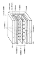
ポンプ10の中央に位置する排気通路容器21において、図1中その上下の両側に排気素子31A,31Bが設けられる。2つの排気素子31A,31Bは、全体の配置関係として、排気通路容器21の中心軸21Bに対して線対称の位置に配置される。ただし2つの排気素子31A,31Bの各々の構成要素の配置関係としては、図1に示すように、対称にはなっておらず、非対称である。排気素子31A,31Bの構造については図2と図3を参照して説明する。2つの排気素子31A,31Bの各々は、排気通路容器21の円筒形の側壁部に取り付けられた箱形の素子容器32の中に配置されている。図1では、上側の排気素子31Aでは例えば15個の径の大きい円筒状陽極セル51Aが示される。15個の大径の陽極セル51Aは、図2に示すように2層構造の排気素子31Aにおいて下側の第1層の円筒陽極51を構成しており、例えば長方形領域に3×5の行列で配列されている。また下側の排気素子31Bでは例えば径の小さい24個の円筒状陽極セル52Aが示される。24個の小径の陽極セル52Aは、同じく図2に示すように2層構造の排気素子31Bにおいて上側の第2層の円筒陽極52を構成しており、例えば長方形領域に4×6の行列で配列されている。
In the
図2と図3において排気素子31A,31Bの内部構造を示す。2つの排気素子31A,31Bは共に同一の構造を有している。排気素子31A,31Bは、断面コ字型の素子容器枠体32Aの内部空間の中に、3枚の陰極板41,42,43を所要の間隔をあけて平行に配置し、さらに下側の2枚の陰極板41,42の間に第1層(第1の種類)の円筒陽極51を配置し、上側の2枚の陰極板42,43の間に第2層(第2の種類)の円筒陽極52を配置した構造を有している。なお図2では、図解の便宜上、素子容器32を形成する右側端部壁と左側端部壁を除いて示しているので、素子容器32は、素子容器枠体32Aとして示されている。また素子容器32の手前側の部分は、上記の排気通路容器21に接続される部分であり、開放された形状部分(開口部)を有し、排気通路容器21の内部空間21Aと通じている。排気素子31A,31Bにおける3枚の陰極板41〜43と2種の円筒陽極51,52とから成る電極構造部50(陰極構造および陽極構造から構成される)は、2層の円筒陽極51,52を有する非対称な2階建て構造となっている。1階に位置する第1層の円筒陽極51は前述した通りの例えば15個の陽極セル51Aにより構成される。2階に位置する第2層の円筒陽極52は前述した通りの例えば24個の陽極セル52Aにより構成される。素子容器枠体32Aの外側には断面コ字型の永久磁石53が配置される。永久磁石53は、図2と図3において、上側端部53aがN極であり、下側端部53bがS極である。素子容器32は、永久磁石53で覆われ、かつその上部分とその下部分とで挟まれている。永久磁石53のN極部分(上側部分53a)からS極部分(下側部分53b)へ向かって磁界が生じている。
2 and 3 show the internal structure of the
上記の構造を有する排気素子31A,31Bにおいて、図3に示すように、前述した素子容器32の内部に配置される3枚の陰極板41〜43および2層の円筒陽極51,52、および素子容器32の外側に配置される永久磁石53の構造にて、3枚の陰極板41〜43はすべてアースEに接続され、かつ第1層の円筒陽極51と陰極板41,42との間には第1の高電圧電源54によって高電圧が印加され、第2層の円筒陽極52と陰極板42,43との間には第2の高電圧電源55によって他の高電圧が印加されている。
In the
上記の上下の2種類の円筒陽極51,52の各電圧状態は、対応する高電圧電源54,55によって別個に制御される。径の大きい円筒状陽極セル51Aから成る円筒陽極51は主として希ガス(アルゴン、ヘリウム、ネオン、クリプトン、キセノン)を吸着し排気するポンプである。またもう一方の径の小さい円筒状陽極セル52Aから成る円筒陽極52は主として水素、空気、炭化水素、水、二酸化炭素、一酸化炭素などの残留ガスを吸着し排気するポンプである。
The voltage states of the two upper and lower
図1において、上側の排気素子31Aは、前述した通り1階側(第1層)の円筒陽極51が図中手前側になるように排気通路容器21に取り付けられている。また下側の排気素子31bは、前述した通り2階側(第2層)の円筒陽極52が図中手前側になるように取り付けられている。また排気通路容器21では高電圧導入端子56が設けられている。高電圧導入端子56は、高電圧導入碍子57を介して高電圧電流導入部58を備える。
In FIG. 1, the
排気通路容器21に取り付けられた2つの排気素子31A,31Bの各々で排気通路容器21との接続部分は開放されている。図1で、領域61,62は熱電子放出フィラメント26から放出された電子が排気素子31A,31Bに向かって移動する電子通過域である。こうして熱電子放出フィラメント26は、排気素子31A,31Bの2階建ての円筒陽極51,52を臨む位置に配置されている。
Each of the two
後述するように、スクロールポンプ209やターボ分子ポンプ205の補助的動作に基づき上記の真空容器11内の真空度が10−3Pa台になったときに、高電圧直流電源54,55により高電圧を発生させ、当該高電圧を高電圧導入端子56の高電圧電流導入部58より高電圧導入碍子57を経て、通電線59,60を介して、排気通路容器21に取り付けられた2台の排気素子31A,31Bの各々の円筒陽極51と円筒陽極52に導く。排気素子31A,31Bの円筒陽極51,52の各陽極セル51A,52Aには所要のプラス電圧が印加され、かつ素子容器32の外側に取り付けられた永久磁石53の磁界が作用し、その結果、排気素子31A,31Bにおいてマグネトロン放電(ぺニング放電)が開始される。これにより排気素子31A,31Bは極高真空用真空ポンプとしての動作を開始し、吸気口フランジ22を通して排気通路容器21の内部空間21Aが極高真空となるように排気動作を行うようになる。この時、多量のゲッター合金を製造し、極高真空域の水素排気に備える。
As will be described later, when the degree of vacuum in the
電子銃25の熱電子放出フィラメント26は、ベークアウト(焼出)の作動の後半以降に使用される。熱電子放出フィラメント26は通電により加熱され、電子を放出する。熱電子放出フィラメント26から放出されかつ電界により加速された電子は円筒陽極51,52に向かって移動する。当該熱電子が円筒陽極51,52の全体に当たるように、その電子通過域61,62には他の部品を置かないようにする。
The
排気素子31A,31Bに設けられた3つの陰極板41〜43の各々は、ゲッター合金薄膜を構成する材料金属を2種以上用いて作られている。円筒陽極51,52は、極高真空用のポンプ10において、その中で発生させたペニング放電によりスパッタを行うことで作製したゲッター合金薄膜で覆われている。
Each of the three
ポンプ10では、超高真空より高い真空度を有する極高真空の領域での排気を促進するため、電子銃25の熱電子放出フィラメント26から放出された熱電子を例えば80〜800Vの範囲に含まれる電圧によって加速して排気素子31A,31Bに導入し、円筒陽極51,52での電流を10〜2000倍(10μA〜2mA)流す。これにより円筒陽極51,52を活性化し、残留水素分子を水素原子に解離し、陰極板41〜43と円筒陽極51,52の表面上のゲッター合金薄膜(水素吸蔵特性を有する金属薄膜)に吸収させ、排気する。このゲッター合金薄膜は活性なガスに対してもゲッターとして働く。
In the
一般的に、電子を放出するエミッター(熱電子源等)をマイナス電位に保ち例えば600〜800Vの電位差に基づいて電子を加速すると、電子衝撃脱離に基づいて脱ガスを行うことができる。しかし、この場合には、真空計に電子が入り込み、真空計が使用できなくなる。他方、電子衝撃効果は限定的になるが、エミッターをプラス電位に保てば、真空計のイオンコレクター(−)に電子が混入することはなくなる。脱ガス後、エミッターをプラス電位に保つ状態に保てば、水素ポンプの電子不足は解消される。 In general, when an emitter (thermionic source or the like) that emits electrons is kept at a negative potential and the electrons are accelerated based on a potential difference of, for example, 600 to 800 V, degassing can be performed based on electron impact desorption. However, in this case, electrons enter the vacuum gauge and the vacuum gauge cannot be used. On the other hand, although the electron impact effect is limited, if the emitter is kept at a positive potential, electrons are not mixed into the ion collector (−) of the vacuum gauge. If the emitter is kept at a positive potential after degassing, the shortage of electrons in the hydrogen pump is resolved.
排気素子31A,31Bの電極構造部50に設けられた3枚の陰極板41〜43は、ゲッター合金薄膜を構成する2種以上の金属材料から作られる。具体的に、例えば、陰極板41はタンタル(Ta)と非磁性金属(通常ではモリブデン(Mo))とから成る金属材料で作られ、陰極板42はジルコニウム(Zr)とアルミ二ウム(Al)とから成る金属材料で作られ、陰極板43はチタニウム(Ti)と非磁性金属(通常ではインコネルまたはステンレス)とから成る金属材料で作られる。陰極板41と陰極板42は対で使用され、また陰極板42と陰極板43も対で使用される。
The three
希ガスが多い場合も、使用する陰極は、同様にゲッター合金薄膜を構成する金属材料から形成される。この場合、陰極板41と陰極板42の対が使用される。
Even when there are many rare gases, the cathode to be used is similarly formed from a metal material constituting the getter alloy thin film. In this case, a pair of
1つの排気素子当たり、永久磁石53による磁場と、陰極板41〜43および円筒陽極51,52に基づく電場とを直交させ、1〜7kVでぺニング放電させるポンプ10において、残留ガス分析計の分圧の多少に応じて高電圧電源を制御することにより、要求残留ガスの分圧を制御することができる。つまり、本実施形態によるポンプ10によれば、極高真空における真空の質の制御も可能としている。
In the
ポンプ10は、上記のごとく非対称な2階建て構造から成る排気素子31A,31Bを備えている。各排気素子31A,31Bの電極構造部50は3枚の陰極板41〜43と2層(2種)の円筒陽極51,52とから構成される。上側の陰極板43は活性ガス用のチタニウム(Ti)、触媒作用のある遷移金属でかつ非磁性、非腐食性、非酸化性のインコネル(またはステンレス)の陰極であり、中間の陰極板42は水素排気用のジルコニウム(Zr)、ゲッター作用促進のためのアルミニウム(Al)の陰極であり、下側の陰極板41は希ガスを埋め込むためのタンタル(Ta)、多種の残留ガスに対応するためのゲッター金属のモリブデン(Mo)の陰極である。また円筒陽極51は主に希ガス用の陽極であり、円筒陽極52は主に水素と活性ガス排気用の陽極である。
The
上記の陰極板41〜43の陰極材料に関して、希ガスの排気についてはタンタル(Ta)−モリブデン(Mo)ゲッター合金で行い、水素の排気についてはジルコニウム(Zr)−アルミニウム(Al)、およびチタニウム(Ti)−インコネルで行う。水素、窒素、酸素(空気)、炭化水素、水、二酸化炭素、一酸化炭素などの排気については、チタニウム(Ti)に微量遷移金属(インコネル)を加えたもので行う。インコネルは、水素分子を水素原子に解離する触媒作用を有している。
Regarding the cathode material of the
次に図4を参照してポンプ10の他の電子銃100を説明する。電子銃100は、前述したように、2極型低加速熱電子銃である。電子銃100は、中央部に位置する熱電子放出フィラメント101と、熱電子放出フィラメント101を囲むグリッド102とから構成される。熱電子放出フィラメント101は前述した熱電子放出フィラメント26に対応している。熱電子放出フィラメント101の下端部にはフィラメント電源103が接続され、熱電子放出フィラメント101にはフィラメント電源103によって所要の電圧が印加される。フィラメント電源103の印加電圧によって熱電子放出フィラメント101からのエミッション電流を制御する。グリッド102には0〜120Vの範囲に含まれる電圧が印加される。ポンプ10の排気素子31A,31Bは、熱電子放出フィラメント101からのエミッション電流(熱電子)により活性化され、これによりスパッタ量が増加する。ポンプ10内に流れる電流はエミッション電流に支配されるようになる。エミッション電流に基づいてポンプ10による真空度の疎調整を行うことができる。フィラメント電源103のプラス極とアース104との間にはさらに電子加速電源105が接続される。この電子加速電源105によって電子衝撃の度合いやポンプ10による真空度の微調整を行う。
Next, another electron gun 100 of the
熱電子放出フィラメント101がマイナス電位に設定されるときにはポンプ活性化効果と電子衝撃による脱ガス効果とが生じる。また熱電子放出フィラメント101がプラス電位に設定されるときにはポンプ活性化効果が生じる。
When the
なお、上記で説明した電子銃100の熱電子放出フィラメント101の電源に関する構成、その動作およびその制御は、先に説明した熱電子放出フィラメント26についても同じである。相違する点は、フィラメント周囲にグリッド102が設けられているか否かの点だけである。
Note that the configuration, operation, and control of the
次に、図5〜図7を参照して、上記のポンプ10を利用して構成された表面分析装置の極高真空排気システムを説明する。
Next, with reference to FIG. 5 to FIG. 7, an extremely high vacuum exhaust system of a surface analysis apparatus configured using the
図5を参照して極高真空排気システムの構成を説明する。11は前述した真空容器であり、内部に表面分析室が設けられ、真空容器11は表面分析装置を構成している。以下の説明では「表面分析装置11」とも記す。真空容器11は、排気口12を介してポンプ10が接続される。ポンプ10との接続部12には残留ガス分析計201が付設されている。また真空容器11の排気口13にはゲートバルブ202を介して試料導入室が設けられた真空容器203が接続されている。さらに真空容器11の真空計接続部14にはXHV真空計(極高真空計)204が接続されている。XHV真空計204の計測する圧力範囲は10−2〜10−11Paである
The configuration of the ultra-high vacuum exhaust system will be described with reference to FIG.
試料導入室を内蔵する真空容器203には、その排気口にゲートバルブ204を介してターボ分子ポンプ205が接続される。ターボ分子ポンプ205は親機205Aと子機205Bから構成される。この実施例では例えば複合ターボ分子ポンプが望ましい。また真空容器203には、さらに、空気または窒素のリークバルブ206と、バルブ207および接続管208を介してスクロールポンプ209とが付設されている。なお接続管208は、バルブ210を介してターボ分子ポンプ205の子機205Bと接続可能になっており、また空気または窒素のリークバルブ211が付設されている。さらに容器203にはUHV真空計(超高真空計)212が付設されている。UHV真空計(B−Aゲージ)212の計測する圧力範囲は10−2〜10−8Paである。
A turbo
上記において、ゲートバルブ202,204とバルブ206,207,210,211は開閉指令信号に基づいて電磁的に開閉動作を行うように構成され、さらにコンピュータ(マイコン)で構成された制御装置301によってその開閉状態が確認され、かつメモリ302に格納された真空排気制御プログラム303に基づいて上記開閉指令信号に従ってその開閉動作が制御されるように構成されている。ポンプ10、ターボ分子ポンプ205の親機205Aおよび子機205B、スクロールポンプ209の運転作動の開始・継続・停止の各作動状態は、同じく制御装置301の真空排気制御プログラム303に基づいて監視されかつ制御される。残留ガス分析計201の出力信号、XHV真空計(エクストラクタゲージ)204の検出信号、およびUHV真空計212の検出信号は、制御装置301に入力される。これらの信号は、制御装置301のCPUで真空制御プログラム303が実行されるとき、制御対象の動作状態に係る情報として参酌される。さらに、図示していないが、表面分析室の真空容器11、試料導入室の真空容器203、およびポンプ10には所要の箇所に周知のベーキング用ヒータが付設されている。これらのベーキング用ヒータの加熱動作も制御装置301によって適切なタイミングで制御される。
In the above, the
図6と図7に示したフローチャートを参照して表面分析装置11における真空排気の作動を説明する。当該フローチャートは、制御装置301で実施される上記の真空排気制御プログラム303の制御の内容を示している。
The operation of evacuation in the
最初の段階で、制御装置301は、ゲートバルブ202,204と他のバルブ206,207,210,211の各々の開閉の状態を確認する。そして、ゲートバルブ202とバルブ207を開き、ゲートバルブ204とバルブ206,210,211を閉じた状態にしてスクロールポンプ209を作動し(ステップS11)、試料導入室の真空容器203と表面分析室の真空容器11を真空排気する。スクロールポンプ209の作動を継続し、UHV真空計212の検出信号に基づいてその圧力Pの状態を確認して圧力Pが設定値P1に達すると(判断ステップS12でYES)、バルブ207を閉じかつバルブ210を開き、さらに追加的に最初にターボ分子ポンプ205の子機205Bを作動させる(ステップS13)。設定値P1はターボ分子ポンプ205の子機205Bの作動を開始させるための条件となる圧力(真空度)である。次いで、ターボ分子ポンプ205の子機205Bの作動を継続し、上記の圧力Pが設定値P2になると(判断ステップS14でYES)、さらに追加的にターボ分子ポンプ205の親機205Aを作動させる(ステップS15)。設定値P2はターボ分子ポンプ205の親機205Aの作動を開始させるための条件となる圧力(真空度)である。ターボ分子ポンプ205の親機205Aと子機205Bの回転速度が最大になるとき、ゲートバルブ204を開いて、スクロールポンプ209、ターボ分子ポンプ205の親機205Aおよび子機205Bによって試料導入室の真空容器203と表面分析室の真空容器11を真空排気する。スクロールポンプ9、ターボ分子ポンプ205の親機205Aおよび子機205Bの作動を継続し、上記の圧力Pが設定値P3になると(判断ステップS16でYES)、次にポンプ10を作動させる(ステップS17)。このポンプ10の作動は「前作動」に相当し、放電洗浄に係る作動である。上記の設定値P3は、ポンプ10を前作動させるための条件となる圧力(真空度)である。前作動すなわち放電洗浄に係る作動は圧力条件が満たされるとき随時に行われる。次の判断ステップS18において放電洗浄が終了か否かが判断される。判断ステップS18でYESのとき、次にポンプ10、表面分析室の真空容器11、および試料導入室の真空容器203の各々のベーキング用ヒータが給電加熱され、ベークアウトが開始される(ステップS19)。
In the first stage, the
具体的に、UHV真空計212の検出信号に基づき圧力5×10⁻³Paに到達したときにポンプ10が作動を開し、圧力1×10⁻⁴Paになったときにベーキング用ヒータを加熱作動させて上記べークアウトを開始し、ガス放出を開始する。この辺りの真空度で多量のゲッター合金を製造し、極高真空域の排気に備える。
Specifically, the
ベークアウトを開始して(ステップS19)15〜20時間を経過させ、加熱温度が270℃に到った頃、圧力が例えば5×10⁻⁶Pa(設定値P4)に到達したとき(判断ステップS20)、べークアウトを終了する(ステップS21)。設定値P4は、ベークアウトを終了するための条件となる真空度である。ベークアウトが終了すると、自然冷却が開始される。さらに次のステップS21では、ポンプ10の作動状態を本来の真空排気作動とし、当該真空排気作動を継続する。このとき、表面分析室の真空容器11に付設されたXHV真空計204の検出信号に基づき、真空容器11の内部の真空度を監視する。また残留ガス分析計201も随時に動作する。XHV真空計204の検出信号に基づき真空容器11の内部圧力Pが設定値P5となったと判断したとき(判断ステップS22)、次のステップS23が実行される。設定値P5は、具体的に例えば10−7Paの真空度であり、低加速熱電子銃25を作動させるための条件となる真空度である。
When bakeout is started (step S19), 15 to 20 hours have elapsed and the heating temperature reaches 270 ° C., when the pressure reaches, for example, 5 × 10 −6 Pa (set value P4) (judgment step). S20), the bakeout is finished (step S21). The set value P4 is a degree of vacuum that is a condition for terminating the bakeout. When the bakeout is finished, natural cooling is started. Further, in the next step S21, the operation state of the
ステップS23では、電子銃25が作動し、熱電子放出フィラメント26からポンプ10の排気素子31A,31Bに対して電子が供給される。また測定機器の脱ガスが行われる。上記の残留ガス分析計201の検出信号に基づいて残留ガスが水素だけになったか否かを判断し、水素だけになったことを条件としてガス放出を終了する(判断ステップS24)。このときの真空容器11の内部圧力は2×10⁻⁷Pa前後であり、容器温度は30℃以下である。炭化水素が残留するときは、熱電子量を増加し、分解を促すようにする。
In step S23, the
XHV真空計204の検出信号に基づき真空容器11の内部真空度Pが5×10⁻⁹Paになったことを確認してゲートバルブ202を閉じかつ電子銃25の作動を調整する。そしてターボ分子ポンプ205とスクロールポンプ209の各作動を停止する(ステップS25)。その後は真空排気装置としてポンプ10のみを作動させ、表面分析装置11、すなわち表面分析計を内蔵する真空容器11の内部真空度を高くし、真空容器11の内部真空度は5×10⁻¹¹Paを経て真空計測不能な極高真空度(10−12Pa)に到達する。
Based on the detection signal of the
判断ステップS26は、真空容器11の内部真空度Pが設定値P6になったか否かを判断する。設定値P6は、電子銃25の作動制御を調整するための条件となる真空度である。判断ステップS26でYESのときに上記のごとく電子銃25の作動を調整する。判断ステップS26の次のステップS27において、上記のごとく、真空容器11の内部真空度が真空計測不能な極高真空度に到達する。そして、その時、真空容器11、当該真空容器11に内蔵される構成ユニットおよび構成部品からのガス放出の減少を待つ。そして、条件が満たされたときに、ゲートバルブ202を開き、試料導入室の真空容器203から分析対象である試料が表面分析室を内蔵する真空容器11内に導入される。試料の導入が完了した後にゲートバルブ202は閉じ、表面分析装置11において試料の表面計測等の仕事が行われる。当該仕事が終了すると、再びゲートバルブ202を開き、試料を真空容器11から真空容器203に取り出す。その後、再びゲートバルブ202を閉じる。なおこの際、分析対象の試料が複数個ある場合には、試料導入と表面計測等の仕事を繰り返す。仕事が全て完了した状態で、ステップS27から次の判断ステップS28へ移行する。
In the determination step S26, it is determined whether or not the internal vacuum degree P of the
判断ステップS28では、極高真空排気装置すなわちポンプ10の作動を停止するための信号が入力された否かが判断される。判断ステップS28でYESであるときには、次のステップS29に移行する。ステップS29では、ポンプ10、ターボ分子ポンプ205、スクロールポンプ209の各作動を停止する。この際、併せて、UHV真空計212の動作を停止し、ゲートバルブ204を閉じ、N2リークバルブ206,211を開く。なお、図5に示した表面分析装置11の極高真空排気システムの全体を長期間停止させる場合には、XHV真空計204の動作を停止し、さらに電子銃25を停止し、電源をオフする。
In the determination step S28, it is determined whether or not a signal for stopping the operation of the ultra-high vacuum evacuation device, that is, the
次に図7を参照して上記の表面分析装置11の極高真空排気システムのポンプ10の性能評価と停電時等の再起動の制御動作の流れを説明する。前提として、図6に示した制御の流れにおいて、ステップS17,S21等によって作動状態にあったポンプ10が停電等で停止してしまった状態にある。
Next, referring to FIG. 7, the flow of the control operation for restarting the performance of the
最初の判断ステップS31では、真空容器11の内部圧力が設定値P7よりも小さいか否かが判断される。この設定値P7は、具体的には例えば5×10⁻⁷Pa程度であり、ポンプ10を再起動させることができる真空度である。判断ステップS31でNOである場合には、真空容器11等の内部真空度が5×10⁻⁷Paよりも高い真空度であるので、ステップS32に移行し、このステップS32においてそれぞれの真空度に対応した再起動の制御が実行される。
In the first determination step S31, it is determined whether or not the internal pressure of the
判断ステップS31でYESである場合には、真空容器11等の内部真空度が5×10⁻⁷Paに等しいまたは当該真空度よりも高いので、ポンプ10の作動を開始し(ステップS33)、さらに真空度を高める。しかしながらポンプ10の排気能力が低下し、次の判断ステップS34でP≧P7であると判断される場合には、電子銃25を動作させて脱ガスを実行し、かつ残留ガス分析計201を動作させて残留ガス成分を確認する(ステップS35)。電子銃25を作動させ、脱ガスを行いながら、ポンプ10の作動を継続する(ステップS35)。その状態で、図6に示したフローチャートにおいて結合子Bを経由して判断ステップ26に移行する。その後の動作の流れは、前述した通りである。
If YES in the determination step S31, the degree of internal vacuum of the
上記の構成では、スクロールポンプ209等のドライポンプを初段とし真空排気動作を行わせ、さらにタンデムにつないだ親機205Aと子機205Bから成る複合ターボ分子ポンプ205によって真空排気の動作を行わせ、ペニング放電のためのプラズマを安定に点火させる真空を得るようにしている。スクロールポンプ209とターボ分子ポンプ205の作動による真空排気の段階での真空度は10−4Paである。このときには、ゲートバルブ202は開かれて真空容器203と表面分析室の真空容器11とは連通した状態にあり、2つの真空容器11,203は共に真空排気される。
In the above configuration, the vacuum pumping operation is performed with the dry pump such as the
さらにその後に、真空容器11に対して前述した本実施形態に係るポンプ10を動作させ、極高真空への真空排気を行い、真空容器11等の内部の真空度を極高真空のレベルに高める。その後、ポンプ10、表面分析室の真空容器11、および試料導入室の真空容器203について例えば270℃の温度でベークアウトを実施する(ステップS19)。ベークアウトは15時間から20時間継続され、その後にベークアウトを停止し、極高真空を得るシステム構成とする。
Further, after that, the
ベークアウト後の残留ガスについては、水素、一酸化炭素とメタン、希ガスの3つのグループに分ける。「水素」は、ポンプ10の排気素子31A,31Bの陰極板41〜43でZr−Ti合金を作製しつつ排気する。「希ガス」はターボ分子ポンプ205と陰極板41〜43でのZr−Ta合金、Ta−Mo合金で排気する。また「炭化水素」は、ベークアウトしながらターボ分子ポンプ205(親機205A、子機205B)で排気する。
Residual gases after bakeout are divided into three groups: hydrogen, carbon monoxide and methane, and noble gases. “Hydrogen” is exhausted while producing a Zr—Ti alloy by the
水素の排気能力が不足する場合は、電子銃25の熱電子放出フィラメント26(熱電子源)から排気素子31A,31Bに向けて電子を放射し、水素排気を加速する。この電子銃25は、ポンプ10での電流調節機能を有している。当該電流は、目的とする真空度の粗調整としての役目を果たし、電圧は微調整の役目を果たす。
When the exhaust capability of hydrogen is insufficient, electrons are emitted from the thermionic emission filament 26 (thermoelectron source) of the
ポンプ10の排気素子31A,31Bに臨む少し離れた位置に配置される熱電子放出フィラメント26は、熱電子を80〜200Vに加速して排気素子31A,31Bの内部にその開口部を介して照射し、ポンプ10の放電電流を10〜2000倍多く流すことにより、極高真空排気用のポンプ10の排気素子31A,31Bを活性化する。これにより、主に水素分子を水素原子に解離し、陰極部および陽極部のゲッター合金薄膜(水素吸蔵合金の役目)に吸収させ、排気する。
The
本実施形態の構成によれば、ポンプ10の排気素子31A,31Bを非対称2階建て構造とし、陰極部分(陰極板41〜43)の全体の表面積を増やし、電子銃25を設けて残留ガスの排気に対応した陰極を構成する合金ゲッター金属材料をスパッタし続けることにより、常に活性な薄膜を製造し、真空度を予め指定した通り自由に自動的に制御することができる。ガス導入ユニットを付属させ、残留ガス分析計201の検出信号に基づいて長時間一定の真空度に保つことに対応することもできる。
According to the configuration of the present embodiment, the
陰極板41〜43に関して、本実施形態で使用する陰極の材料は、ゲッター合金の組成金属材料にしてスパッタされて活性なゲッター合金薄膜を作製し続け、水素分子の解離、排気を可能とし、多くの二次電子を発生させるために、陰極表面に、仕事関数の小さい炭化ジルコニウム(ZrxCy)を作製する。ジルコニウム(Zr)−アルミニウム(Al)合金、タンタル(Ta)−モリブデン(Mo)合金、およびチタニウム(Ti)−非磁性遷移金属合金(インコネル)の3種類の陰極材料を使用して、2種類の活性な合金ゲッター薄膜を作製し続け、使用する。
Regarding the
放電を継続するのに不足する電子を補うために、排気素子31A,31Bの円筒陽極を51,52に臨む離れた位置に配置された電子銃25の熱電子フィラメント26から熱電子をわずかに加速して導入し、ポンプ10の放電電流を多く流すことによりポンプ10を活性化し、電気的制御可能として、ガス分子減少によるポンプ性能降下を阻止し、主に水素分子を水素原子に解離し陰陽極に作製した触媒を含むゲッター合金および水素吸蔵合金に吸収させて排気する。
In order to make up for the electrons that are insufficient to continue the discharge, the thermal electrons are slightly accelerated from the
ここで最適なゲッター合金の製造方法を説明する。ポンプ10内において発生させたプラズマ(放電)によってスパッタを繰り返すことで新鮮で最適なゲッター合金を製造することができる。また、真空度が良くなると活性なゲッター合金ができる、活性な排気特性の良いゲッター合金ができると真空度が良くなる、という好循環が生まれ、真空度は測定限界を超えてどんどん良くなる。例えば、窒素に最適な合金ゲッターができれば窒素と反応し、酸素に最適なゲッター合金ができれば酸素と反応する。残留ガスの水素については解離が必要なので、清浄金属表面の触媒効果や電子のエネルギーを必要とし、導入熱電子が排気促進剤としての役割を果たす。つまり、この場合、「残留ガスによるゲッター合金選択効果」が働く。
Here, an optimum method for producing a getter alloy will be described. A fresh and optimum getter alloy can be manufactured by repeating sputtering by plasma (discharge) generated in the
活性なガスとゲッター合金の化学反応生成物、TiO2、ZrO2、Al2O3、Ti3N4、Zr3N4、AlN、TiC、ZrC等は誘電体であるため、スパッタされにくく、系外に除かれる。特にZrCは電子放出源として寄与する。 Chemical reaction products of active gas and getter alloy, TiO 2 , ZrO 2 , Al 2 O 3 , Ti 3 N 4 , Zr 3 N 4 , AlN, TiC, ZrC, and the like are dielectric materials, so are not easily sputtered, Removed outside the system. In particular, ZrC contributes as an electron emission source.
スパッタの際、周辺にもれた陰極を構成する金属粒子は、ポンプ10の排気通路容器21内の壁に付着し続け、常温で排気通路容器21からの水素遮断と容器表面が水素吸蔵機能を持つ水素排気用の真空ポンプとなる。
At the time of sputtering, the metal particles constituting the cathode that have leaked to the periphery continue to adhere to the wall in the
上記のポンプ10に基づくガスの排気では、個々のガスについて次のような現象が起きる。
(1)水素(含む重水素)
中間の陰極板42の表裏のジルコニウムとアルミニウム、ニッケル、鉄がつくるゲッター合金、および2階天井部の陰極43のチタニウムと鉄からなるゲッター合金との間で固溶体を作る。
(2)水と炭化水素
チタニウムとジルコニウム、鉄と化学反応する。
(3)希ガス(アルゴン、ヘリウム、ネオン、クリプトン、キセノン)
親子のターボ分子ポンプ205が用いられているので、大部分はこのターボ分子ポンプ205により排気される。またタンタルとモリブデンによってスパッタされない部分に埋め込まれる。
(4)活性なガス(窒素、酸素、一酸化炭素、二酸化炭素)
チタニウムとジルコニウム、アルミニウムと化学反応する。
In the exhaust of gas based on the
(1) Hydrogen (including deuterium)
A solid solution is made between the getter alloy made of zirconium, aluminum, nickel, and iron on the front and back surfaces of the
(2) Water and hydrocarbons Chemically react with titanium, zirconium and iron.
(3) Noble gas (argon, helium, neon, krypton, xenon)
Since the parent and child turbo
(4) Active gas (nitrogen, oxygen, carbon monoxide, carbon dioxide)
Chemically reacts with titanium, zirconium, and aluminum.
次に、図8を参照して、本発明の第2実施形態に係る極高真空水素ポンプを説明する。この装置構成では、排気素子を1個として小型化している。
小型化のために排気素子31Cを1つにしても、排気素子31Cの電極構造部50については3つの陰極板41〜43と2種の円筒陽極51,52とから成る2階建て構造を採用しているため、性能を維持することができる。
Next, an ultra-high vacuum hydrogen pump according to a second embodiment of the present invention will be described with reference to FIG. In this apparatus configuration, the exhaust element is reduced to one size.
Even if there is only one
図8において、21は排気通路容器、22は吸気口フランジ、32は素子容器、53は永久磁石、26は熱電子放出フィラメント(1極型低加速熱電子銃25)、56は高電圧導入部、101は熱電子放出フィラメント(2極型低加速熱電子銃100)、102はグリッド、401は電子通過域、402は取付金具である。図8の図示例では、1極型低加速熱電子銃25と2極型低加速熱電子銃100を、排気素子31Cの円筒陽極51,52に臨むように設置している。放出された電子が円筒陽極の全体に当たるよう電子通過域401には真空部品を置かないようにする。
In FIG. 8, 21 is an exhaust passage container, 22 is an inlet flange, 32 is an element container, 53 is a permanent magnet, 26 is a thermoelectron emission filament (one pole type low acceleration thermoelectron gun 25), and 56 is a high voltage introduction part. , 101 is a thermoelectron emission filament (bipolar low acceleration thermoelectron gun 100), 102 is a grid, 401 is an electron passage region, and 402 is a mounting bracket. In the illustrated example of FIG. 8, the unipolar low
第2の実施形態の構成の場合にも、第1の実施形態の場合と同様に、2種類の合金ゲッターを維持できるので、性能を落とすことなく小型軽量化に対応できる。本実施形態では、電子銃25等と高電圧導入部56との位置関係は図8に示すように同じ側である。なお第1の実施形態で説明したように反対側に設けることもできる。また装置の大型化のためには排気素子の容器を4個に増やしたり、個数は2個であってもその長さを長くすることにより、到達真空度を高い高速排気を行うことができるという本発明の効果を得ることができる。
Also in the case of the configuration of the second embodiment, as in the case of the first embodiment, two types of alloy getters can be maintained, so that it is possible to cope with a reduction in size and weight without reducing performance. In the present embodiment, the positional relationship between the
その他の変形例としては次の通りである。
(1)排気素子31A〜31Cの円筒陽極51,52が静電レンズ作用を生じるように構成することもできる。
この構成によって同一場所のスパッタを避けることができる。プラズマ点火の当初は、リング状の領域に放電しているが、圧力が10−4Pa台では放電が中心部に集まり、さらに圧力が10−5Paより高くなり真空度がよくなると、放電はますます収束し点状になる。中心部に偏ったスパッタでは、スパッタされる陰極の金属の量が制限され、活性化される面積が減少するので、排気効率が悪くなる。そこで静電レンズの作用効果を利用してスパッタ面積を拡大し、陰極表面の活性化を促進するようにする。こうすることにより陰極の金属内部への熱拡散も増加する。
(2)中間に位置する陰極板42の中心部および周辺部に小さな穴を開けて1階部分をファラデーカップにすることができる。
このような構成を採用すると、スパッタによる再放出をさけることができるので、特に希ガスに対して有効な手段となる。非対称にした意味がここで有効に生かされる。ファラデーカップ効果が不足する場合、1階部分と同じ高さの3階部分を設けてもよい。
(3)電子衝撃脱離の脱ガスへ適用することができる。
この構成は、べークアウトの温度を少しでも下げるために、ポンプ10の真空容器の全体加熱と併用する。一次電子、反射電子、二次電子によって、残留ガス、表面吸着ガス、容器材料に溶解しているガスをイオン化し、ゲッター合金との化学反応を促進し排気効率を上げる。
使用される電子銃については、前述した通り、熱電子放出フィラメントがグリッドを備えない1極型低加速熱電子銃26と、熱電子放出フィラメント101がグリッド102の内にある2極型低加速熱電子銃100がある。2極型低加速熱電子銃100は電子の制御が容易になる。
Other modifications are as follows.
(1) The
With this configuration, spattering at the same place can be avoided. At the beginning of plasma ignition, discharge is generated in a ring-shaped region. When the pressure is in the range of 10 −4 Pa, the discharge collects in the center, and when the pressure is higher than 10 −5 Pa and the degree of vacuum is improved, Increasingly converges and becomes point-like. Sputtering biased toward the center limits the amount of cathode metal to be sputtered and reduces the activated area, resulting in poor exhaust efficiency. Therefore, the sputtering area is enlarged by utilizing the action effect of the electrostatic lens to promote the activation of the cathode surface. This also increases the thermal diffusion of the cathode into the metal.
(2) A small hole can be made in the central part and the peripheral part of the
If such a configuration is adopted, re-emission due to sputtering can be avoided, which is an effective means particularly for a rare gas. The asymmetric meaning is effectively utilized here. When the Faraday cup effect is insufficient, a third floor portion having the same height as the first floor portion may be provided.
(3) It can be applied to degassing of electron impact desorption.
This configuration is used in combination with the overall heating of the vacuum vessel of the
As for the electron gun to be used, as described above, the one-pole type low
本発明の実施形態に係る極高真空水素ポンプを適用した場合の真空排気特性のデータを図9〜図11に示す。図9は残留ガス分析計201から得られる全ガスが検出されない場合についてのデータである。図10は水素のみのデータである。図11は水素のないデータである。
The data of the evacuation characteristics when the ultra-high vacuum hydrogen pump according to the embodiment of the present invention is applied are shown in FIGS. FIG. 9 shows data when the total gas obtained from the
以上の実施形態で説明された構成、形状、大きさおよび配置関係については本発明が理解・実施できる程度に概略的に示したものにすぎず、また数値および各構成の組成(材質)等については例示にすぎない。従って本発明は、説明された実施形態に限定されるものではなく、特許請求の範囲に示される技術的思想の範囲を逸脱しない限り様々な形態に変更することができる。 The configurations, shapes, sizes, and arrangement relationships described in the above embodiments are merely schematically shown to the extent that the present invention can be understood and implemented, and the numerical values and the compositions (materials) of the respective components Is just an example. Therefore, the present invention is not limited to the described embodiments, and can be variously modified without departing from the scope of the technical idea shown in the claims.
本発明に係る極高真空水素ポンプは、安定した極高真空(10−8Paより小さい圧力の真空度)を必要する低速電子線回折や光電子分光、オージェ電子分光、冷陰極電子銃、加速器等などの排気システムの装置として広く利用される。 The ultra-high vacuum hydrogen pump according to the present invention includes low-energy electron diffraction, photoelectron spectroscopy, Auger electron spectroscopy, cold cathode electron gun, accelerator, etc. that require a stable ultra-high vacuum (vacuum degree less than 10 −8 Pa). It is widely used as an exhaust system device.
10 極高真空水素ポンプ
11 真空容器
21 排気通路容器
21A 排気通路
25 1極低加速熱電子銃
26 熱電子放出フィラメント
31A 排気素子
31B 排気素子
31C 排気装置
32 素子容器
41〜43 陰極板
51 円筒陽極
51A 陽極セル
52 円筒陽極
52A 陽極セル
53 永久磁石
100 2極型低加速熱電子銃
101 熱電子放出フィラメント
102 グリッド
201 残留ガス分析計
202 ゲートバルブ
203 真空容器
204 ゲートバルブ
205 ターボ分子ポンプ
209 スクロールポンプ
301 制御装置
DESCRIPTION OF
Claims (7)
前記真空容器に接続される排気通路容器と、
前記排気通路容器に取り付けられその内部空間に通じる開口部を有する素子容器と、この素子容器内に配置され、3つの陰極と円筒陽極とから構成される2階建て構造を有しかつ第1の前記陰極と第2の前記陰極の間および第2の前記陰極と第3の前記陰極の間に前記円筒陽極が配置される電極構造部と、この電極構造部の前記2階建て構造における高さ方向に磁界を作る磁石とを備える少なくとも1台の排気素子と、
前記排気通路容器の前記内部空間に臨むように配置された電子銃とを備える極高真空水素ポンプにおいて、
前記電極構造部は、形状が異なる第1および第2の前記円筒陽極を備え、前記第1陰極と前記第2陰極の間に前記第1円筒陽極が配置されかつ前記第2陰極と前記第3陰極の間に前記第2円筒陽極が配置され、前記2階建て構造が非対称に形成され、
前記3つの陰極はゲッター合金の薄膜を形成する材料金属である2種以上を陰極材料で作られ、前記陰極と前記円筒陽極の間に発生したマグネトロン放電で前記陰極をスパッタすることにより水素を吸蔵する前記ゲッター合金を前記陰極の表面と前記円筒陽極の表面と前記排気通路容器の内面に作製し続けて前記陰極の表面と前記円筒陽極の表面と前記排気通路容器の内面はポンプ作動中継続して前記ゲッター合金の前記薄膜で覆われ、
前記電子銃は熱電子放出フィラメントを有する、
ことを特徴とする極高真空水素ポンプ。 An ultra-high vacuum hydrogen pump that exhausts the inside of a vacuum vessel to be evacuated to a degree of vacuum higher than 10 −8 Pa,
An exhaust passage container connected to the vacuum container;
An element container that is attached to the exhaust passage container and has an opening that communicates with the internal space thereof, and a two-story structure that is disposed in the element container and includes three cathodes and a cylindrical anode, and a first structure An electrode structure portion in which the cylindrical anode is disposed between the cathode and the second cathode and between the second cathode and the third cathode, and a height of the electrode structure portion in the two-story structure At least one exhaust element comprising a magnet that creates a magnetic field in the direction;
In an ultra-high vacuum hydrogen pump comprising an electron gun arranged to face the internal space of the exhaust passage container,
The electrode structure portion includes first and second cylindrical anodes having different shapes, the first cylindrical anode is disposed between the first cathode and the second cathode, and the second cathode and the third cathode The second cylindrical anode is disposed between the cathodes, and the two-story structure is formed asymmetrically;
The three cathodes are made of a cathode material made of two or more metals that form a getter alloy thin film, and the cathode is sputtered by a magnetron discharge generated between the cathode and the cylindrical anode to absorb hydrogen. The getter alloy is continuously formed on the surface of the cathode, the surface of the cylindrical anode, and the inner surface of the exhaust passage container, and the surface of the cathode, the surface of the cylindrical anode, and the inner surface of the exhaust passage container continue during the pump operation. Covered with the thin film of the getter alloy,
The electron gun has a thermionic emission filament;
An ultra-high vacuum hydrogen pump characterized by that.
前記残留ガス分析計から出力される信号に応じて、前記電子銃の電源を制御し、要求残留ガスの分圧を制御する制御手段と、
を備えることを特徴とする請求項1〜4のいずれか1項に記載の極高真空水素ポンプ。 A residual gas analyzer;
In accordance with a signal output from the residual gas analyzer, control means for controlling the power source of the electron gun and controlling the partial pressure of the required residual gas;
The ultrahigh vacuum hydrogen pump according to any one of claims 1 to 4, wherein the ultrahigh vacuum hydrogen pump is provided.
径の大きい複数の円筒状陽極セルによって構成される前記第1円筒陽極は主に希ガスの排気に使用され、
径の小さい複数の円筒状陽極セルによって構成される前記第2円筒陽極は、主に、水素、空気、炭化水素、水、二酸化炭素、一酸化炭素を含む残留ガスの排気に使用される、
ことを特徴とする請求項1記載の極高真空水素ポンプ。 The operation of the power source for applying a voltage to each of the two types of cylindrical anodes is controlled separately,
The first cylindrical anode constituted by a plurality of cylindrical anode cells having a large diameter is mainly used for exhausting rare gas,
The second cylindrical anode constituted by a plurality of cylindrical anode cells having a small diameter is mainly used for exhausting residual gas including hydrogen, air, hydrocarbon, water, carbon dioxide, and carbon monoxide.
The ultra-high vacuum hydrogen pump according to claim 1.
排気通路容器に取り付けられその内部空間に通じる開口部を有する素子容器と、この素子容器内に配置され、それぞれゲッター合金の薄膜を形成する材料金属である2種以上を陰極材料で作られる3つの陰極と円筒陽極とから構成される非対称の2階建て構造を有しかつ第1の前記陰極と第2の前記陰極の間に第1の前記円筒陽極が配置されかつ第2の前記陰極と第3の前記陰極の間に第2の前記円筒陽極が配置される電極構造部と、この電極構造部の前記2階建て構造における高さ方向に磁界を作る磁石とを備える少なくとも1台の排気素子に対して、前記排気通路容器の前記内部空間に臨むように配置された熱電子放出フィラメントを有する電子銃と、
残留ガス分析計と、
前記電子銃の電源を制御する制御手段と、を備え、
前記排気素子では、前記陰極と前記円筒陽極の間にはマグネトロン放電が生成され、
前記マグネトロン放電で前記陰極をスパッタすることによって、水素を吸蔵する前記ゲッター合金を、前記陰極の表面、前記円筒陽極の表面、および前記排気通路容器の内面に作製し続けるように、前記制御手段は、前記残留ガス分析計から出力される信号に応じて、前記電子銃の電源を制御し、これにより要求残留ガスの分圧を制御することを特徴とする極高真空水素ポンプの熱電子制御装置。 A thermoelectronic control device used for an ultra-high vacuum hydrogen pump that exhausts the inside of a vacuum vessel to be evacuated to a degree of vacuum higher than 10 −8 Pa,
An element container having an opening communicating with the internal space is attached to the exhaust passage vessel 3 this is placed in the element within the container is made of two or more thereof is a metallic material for forming a thin film of getter alloy cathode material An asymmetric two-story structure composed of two cathodes and a cylindrical anode, and the first cylindrical anode is disposed between the first cathode and the second cathode, and the second cathode At least one exhaust comprising: an electrode structure part in which the second cylindrical anode is arranged between the third cathodes; and a magnet that creates a magnetic field in the height direction in the two-story structure of the electrode structure part. An electron gun having a thermionic emission filament disposed so as to face the internal space of the exhaust passage container with respect to the element;
A residual gas analyzer;
Control means for controlling the power source of the electron gun,
In the exhaust element, a magnetron discharge is generated between the cathode and the cylindrical anode,
The control means is configured to continuously produce the getter alloy that occludes hydrogen on the surface of the cathode, the surface of the cylindrical anode, and the inner surface of the exhaust passage container by sputtering the cathode with the magnetron discharge. A thermoelectronic control device for an ultra-high vacuum hydrogen pump that controls a power source of the electron gun in accordance with a signal output from the residual gas analyzer, thereby controlling a partial pressure of a required residual gas .
Priority Applications (1)
| Application Number | Priority Date | Filing Date | Title |
|---|---|---|---|
| JP2010086245A JP5711898B2 (en) | 2010-04-02 | 2010-04-02 | Ultra-high vacuum hydrogen pump and thermionic controller |
Applications Claiming Priority (1)
| Application Number | Priority Date | Filing Date | Title |
|---|---|---|---|
| JP2010086245A JP5711898B2 (en) | 2010-04-02 | 2010-04-02 | Ultra-high vacuum hydrogen pump and thermionic controller |
Publications (2)
| Publication Number | Publication Date |
|---|---|
| JP2011214567A JP2011214567A (en) | 2011-10-27 |
| JP5711898B2 true JP5711898B2 (en) | 2015-05-07 |
Family
ID=44944533
Family Applications (1)
| Application Number | Title | Priority Date | Filing Date |
|---|---|---|---|
| JP2010086245A Active JP5711898B2 (en) | 2010-04-02 | 2010-04-02 | Ultra-high vacuum hydrogen pump and thermionic controller |
Country Status (1)
| Country | Link |
|---|---|
| JP (1) | JP5711898B2 (en) |
Cited By (1)
| Publication number | Priority date | Publication date | Assignee | Title |
|---|---|---|---|---|
| EP4177929A1 (en) * | 2021-11-08 | 2023-05-10 | Hamilton Sundstrand Corporation | Ion pump for use in low gravity environments |
Families Citing this family (5)
| Publication number | Priority date | Publication date | Assignee | Title |
|---|---|---|---|---|
| CN113933454B (en) * | 2021-09-01 | 2024-06-18 | 中国科学院微电子研究所 | Extreme ultraviolet lithography machine material detection device and test method |
| WO2024089576A1 (en) * | 2022-10-27 | 2024-05-02 | Edwards Vacuum Llc | Sputter ion pump |
| GB2623794A (en) * | 2022-10-27 | 2024-05-01 | Edwards Vacuum Llc | Sputter ion pump |
| GB2639524A (en) * | 2023-12-19 | 2025-10-01 | Edwards Vacuum Llc | Sputter ion pump cathode |
| CN119767508B (en) * | 2025-01-02 | 2026-01-13 | 中子科学(重庆)研究院有限公司 | Air suction thin-wall part, preparation method, vacuum chamber assembly and vacuum regulation and control method |
Family Cites Families (4)
| Publication number | Priority date | Publication date | Assignee | Title |
|---|---|---|---|---|
| US5972183A (en) * | 1994-10-31 | 1999-10-26 | Saes Getter S.P.A | Getter pump module and system |
| JP3750767B2 (en) * | 1997-09-09 | 2006-03-01 | 有限会社真空実験室 | Ion pump |
| JP3926206B2 (en) * | 2002-05-24 | 2007-06-06 | 日本電子株式会社 | Ultra-high vacuum exhaust device, vacuum exhaust method, and sputter ion pump |
| JP2007087676A (en) * | 2005-09-21 | 2007-04-05 | Hitachi High-Technologies Corp | Field emission electron gun and electron beam apparatus using the same |
-
2010
- 2010-04-02 JP JP2010086245A patent/JP5711898B2/en active Active
Cited By (1)
| Publication number | Priority date | Publication date | Assignee | Title |
|---|---|---|---|---|
| EP4177929A1 (en) * | 2021-11-08 | 2023-05-10 | Hamilton Sundstrand Corporation | Ion pump for use in low gravity environments |
Also Published As
| Publication number | Publication date |
|---|---|
| JP2011214567A (en) | 2011-10-27 |
Similar Documents
| Publication | Publication Date | Title |
|---|---|---|
| JP5711898B2 (en) | Ultra-high vacuum hydrogen pump and thermionic controller | |
| JP4568321B2 (en) | Cold cathode ionization gauge | |
| JP5372239B2 (en) | Combined pump system including getter pump and ion pump | |
| US20080283745A1 (en) | Emitter chamber, charged partical apparatus and method for operating same | |
| JP5302386B2 (en) | Combined exhaust system comprising a getter pump and an ion pump | |
| US20080284332A1 (en) | Gun chamber, charged particle beam apparatus and method of operating same | |
| JPWO2012090421A1 (en) | Plasma CVD equipment | |
| JP5344609B2 (en) | Ionized sputtering vacuum pump | |
| JPWO2014132758A1 (en) | Orbitron pump and electron beam apparatus using orbitron pump | |
| JP2023517188A (en) | Vacuum module, vacuum device, and method for regenerating volume getter vacuum pump | |
| JP3926206B2 (en) | Ultra-high vacuum exhaust device, vacuum exhaust method, and sputter ion pump | |
| JPH10269930A (en) | Field emission type cold cathode, and manufacture of loading device for the cold cathode | |
| Tominetti et al. | Getters for flat-panel displays | |
| JP2013089538A (en) | Charged particle beam apparatus, and degasification method | |
| JP2001357814A (en) | Ultra high vacuum sputter ion pump | |
| JP2008249559A (en) | Manufacturing method for flocculation system structure, and manufacture device for flocculation system structure | |
| JP3261049B2 (en) | Sputtering method | |
| JP3750767B2 (en) | Ion pump | |
| JP2001192829A (en) | Ecr plasma enhanced cvd system for carbon nanotube thin film deposition, and method of deposition for the thin film | |
| JP4448586B2 (en) | Large diameter carbon nanotube thin film forming plasma CVD apparatus and method for forming the thin film | |
| JP2002313270A (en) | High vacuum electron beam apparatus and exhaust method therefor | |
| JP4531193B2 (en) | Carbon nanotube thin film forming ECR plasma CVD apparatus using slot antenna and method of forming the thin film | |
| JP5175229B2 (en) | Film forming apparatus and operation method thereof | |
| JP6174054B2 (en) | Orbitron pump and electron beam apparatus equipped with orbitron pump | |
| JP2025175396A (en) | Vacuum parts, vacuum pumping methods |
Legal Events
| Date | Code | Title | Description |
|---|---|---|---|
| A621 | Written request for application examination |
Free format text: JAPANESE INTERMEDIATE CODE: A621 Effective date: 20130327 |
|
| A521 | Request for written amendment filed |
Free format text: JAPANESE INTERMEDIATE CODE: A821 Effective date: 20130327 |
|
| A977 | Report on retrieval |
Free format text: JAPANESE INTERMEDIATE CODE: A971007 Effective date: 20131218 |
|
| A131 | Notification of reasons for refusal |
Free format text: JAPANESE INTERMEDIATE CODE: A131 Effective date: 20131224 |
|
| A521 | Request for written amendment filed |
Free format text: JAPANESE INTERMEDIATE CODE: A523 Effective date: 20140219 |
|
| A02 | Decision of refusal |
Free format text: JAPANESE INTERMEDIATE CODE: A02 Effective date: 20140805 |
|
| A521 | Request for written amendment filed |
Free format text: JAPANESE INTERMEDIATE CODE: A523 Effective date: 20141104 |
|
| A911 | Transfer to examiner for re-examination before appeal (zenchi) |
Free format text: JAPANESE INTERMEDIATE CODE: A911 Effective date: 20141112 |
|
| A521 | Request for written amendment filed |
Free format text: JAPANESE INTERMEDIATE CODE: A523 Effective date: 20150120 |
|
| A131 | Notification of reasons for refusal |
Free format text: JAPANESE INTERMEDIATE CODE: A131 Effective date: 20150120 |
|
| TRDD | Decision of grant or rejection written | ||
| A01 | Written decision to grant a patent or to grant a registration (utility model) |
Free format text: JAPANESE INTERMEDIATE CODE: A01 Effective date: 20150303 |
|
| A61 | First payment of annual fees (during grant procedure) |
Free format text: JAPANESE INTERMEDIATE CODE: A61 Effective date: 20150309 |
|
| R150 | Certificate of patent or registration of utility model |
Ref document number: 5711898 Country of ref document: JP Free format text: JAPANESE INTERMEDIATE CODE: R150 |
|
| R250 | Receipt of annual fees |
Free format text: JAPANESE INTERMEDIATE CODE: R250 |
|
| R250 | Receipt of annual fees |
Free format text: JAPANESE INTERMEDIATE CODE: R250 |
|
| R250 | Receipt of annual fees |
Free format text: JAPANESE INTERMEDIATE CODE: R250 |
|
| R250 | Receipt of annual fees |
Free format text: JAPANESE INTERMEDIATE CODE: R250 |
|
| R250 | Receipt of annual fees |
Free format text: JAPANESE INTERMEDIATE CODE: R250 |
|
| R250 | Receipt of annual fees |
Free format text: JAPANESE INTERMEDIATE CODE: R250 |
|
| R250 | Receipt of annual fees |
Free format text: JAPANESE INTERMEDIATE CODE: R250 |
|
| R250 | Receipt of annual fees |
Free format text: JAPANESE INTERMEDIATE CODE: R250 |