JP5705222B2 - Electrically pumped optoelectronic semiconductor chip - Google Patents
Electrically pumped optoelectronic semiconductor chip Download PDFInfo
- Publication number
- JP5705222B2 JP5705222B2 JP2012524169A JP2012524169A JP5705222B2 JP 5705222 B2 JP5705222 B2 JP 5705222B2 JP 2012524169 A JP2012524169 A JP 2012524169A JP 2012524169 A JP2012524169 A JP 2012524169A JP 5705222 B2 JP5705222 B2 JP 5705222B2
- Authority
- JP
- Japan
- Prior art keywords
- semiconductor chip
- quantum well
- active quantum
- beam active
- layer
- Prior art date
- Legal status (The legal status is an assumption and is not a legal conclusion. Google has not performed a legal analysis and makes no representation as to the accuracy of the status listed.)
- Active
Links
Images


Classifications
-
- H—ELECTRICITY
- H10—SEMICONDUCTOR DEVICES; ELECTRIC SOLID-STATE DEVICES NOT OTHERWISE PROVIDED FOR
- H10H—INORGANIC LIGHT-EMITTING SEMICONDUCTOR DEVICES HAVING POTENTIAL BARRIERS
- H10H20/00—Individual inorganic light-emitting semiconductor devices having potential barriers, e.g. light-emitting diodes [LED]
- H10H20/80—Constructional details
- H10H20/81—Bodies
- H10H20/811—Bodies having quantum effect structures or superlattices, e.g. tunnel junctions
- H10H20/812—Bodies having quantum effect structures or superlattices, e.g. tunnel junctions within the light-emitting regions, e.g. having quantum confinement structures
-
- H—ELECTRICITY
- H10—SEMICONDUCTOR DEVICES; ELECTRIC SOLID-STATE DEVICES NOT OTHERWISE PROVIDED FOR
- H10H—INORGANIC LIGHT-EMITTING SEMICONDUCTOR DEVICES HAVING POTENTIAL BARRIERS
- H10H20/00—Individual inorganic light-emitting semiconductor devices having potential barriers, e.g. light-emitting diodes [LED]
- H10H20/80—Constructional details
- H10H20/81—Bodies
- H10H20/822—Materials of the light-emitting regions
- H10H20/824—Materials of the light-emitting regions comprising only Group III-V materials, e.g. GaP
- H10H20/825—Materials of the light-emitting regions comprising only Group III-V materials, e.g. GaP containing nitrogen, e.g. GaN
-
- H—ELECTRICITY
- H01—ELECTRIC ELEMENTS
- H01L—SEMICONDUCTOR DEVICES NOT COVERED BY CLASS H10
- H01L2924/00—Indexing scheme for arrangements or methods for connecting or disconnecting semiconductor or solid-state bodies as covered by H01L24/00
- H01L2924/0001—Technical content checked by a classifier
- H01L2924/0002—Not covered by any one of groups H01L24/00, H01L24/00 and H01L2224/00
-
- H—ELECTRICITY
- H01—ELECTRIC ELEMENTS
- H01L—SEMICONDUCTOR DEVICES NOT COVERED BY CLASS H10
- H01L2924/00—Indexing scheme for arrangements or methods for connecting or disconnecting semiconductor or solid-state bodies as covered by H01L24/00
- H01L2924/10—Details of semiconductor or other solid state devices to be connected
- H01L2924/11—Device type
- H01L2924/12—Passive devices, e.g. 2 terminal devices
- H01L2924/1204—Optical Diode
- H01L2924/12041—LED
Landscapes
- Led Devices (AREA)
- Semiconductor Lasers (AREA)
Description
本発明は、電気的にポンピングされるオプトエレクトロニクス半導体チップに関する。 The present invention relates to an optoelectronic semiconductor chip that is electrically pumped.
刊行物US 6,849,881 B1には、多重量子井戸構造を備えているオプトエレクトロニクス半導体構成素子が開示されている。 Publication US 6,849,881 B1 discloses an optoelectronic semiconductor component having a multiple quantum well structure.
刊行物US 2002/0179923 A1には発光ダイオードが開示されている。 The publication US 2002/0179923 A1 discloses a light-emitting diode.
本発明の解決すべき課題は、電流密度が低くても高効率を示す、電気的にポンピングされる半導体チップを提供することである。 The problem to be solved by the present invention is to provide an electrically pumped semiconductor chip that exhibits high efficiency even at low current densities.
オプトエレクトロニクス半導体チップの少なくとも一つの実施の形態によれば、オプトエレクトロニクス半導体チップは少なくとも二つのビーム活性量子井戸を有している。ビーム活性とは、半導体チップの動作時に、それらの量子井戸において電磁ビームが生成されることを意味している。例えば、各ビーム活性量子井戸においては、半導体チップによって生成される全体のビームに関して、少なくとも2.5%、特に少なくとも4.0%の割合の出力が形成される。ビームの波長は紫外線スペクトル領域及び/又は可視スペクトル領域内、有利には、420nm以上480nm以下の波長にあることが考えられる。 According to at least one embodiment of the optoelectronic semiconductor chip, the optoelectronic semiconductor chip has at least two beam active quantum wells. Beam activity means that electromagnetic beams are generated in these quantum wells during operation of the semiconductor chip. For example, in each beam active quantum well, an output with a proportion of at least 2.5%, in particular at least 4.0%, is formed for the total beam produced by the semiconductor chip. It is conceivable that the wavelength of the beam is in the ultraviolet spectral region and / or in the visible spectral region, advantageously in the wavelength range from 420 nm to 480 nm.
量子井戸構造という概念には量子化の次元に関する意味は含まれていない。従って、量子井戸の概念には例えば多次元の量子井戸、一次元の量子線、0次元と見なすことができる量子点並びにそれらの構造の各組み合わせが含まれている。 The concept of quantum well structure does not include any meaning regarding the dimension of quantization. Therefore, the concept of quantum well includes, for example, multidimensional quantum wells, one-dimensional quantum lines, quantum dots that can be regarded as zero-dimensional, and combinations of their structures.
オプトエレクトロニクス半導体チップの少なくとも一つの実施の形態によれば、オプトエレクトロニクス半導体チップは電気的にポンピングされる。即ち、半導体チップの電気的なp型端子側及び電気的なn型端子側においては、正の電荷又は負の電荷がそれぞれ注入され、それらの電荷が半導体チップの所定の動作時にそれぞれ他方の端子側へと伝播する。半導体チップを通過するこの伝播では、電荷が少なくとも部分的にビーム活性量子井戸に到達し、そこにおいて正の電荷が負の電荷と少なくとも部分的に再結合する。この電荷の再結合によって、半導体チップから放出されるビームが生成される。 According to at least one embodiment of the optoelectronic semiconductor chip, the optoelectronic semiconductor chip is electrically pumped. That is, on the electrical p-type terminal side and electrical n-type terminal side of the semiconductor chip, positive charges or negative charges are respectively injected, and these charges are respectively transferred to the other terminal during a predetermined operation of the semiconductor chip. Propagate to the side. In this propagation through the semiconductor chip, the charge reaches at least partly the beam active quantum well, where the positive charge at least partly recombines with the negative charge. This charge recombination produces a beam emitted from the semiconductor chip.
オプトエレクトロニクス半導体チップの少なくとも一つの実施の形態によれば、ビーム活性量子井戸はInGaNを含有しているか、又はInGaNから構成されている。 According to at least one embodiment of the optoelectronic semiconductor chip, the beam active quantum well contains InGaN or consists of InGaN.
オプトエレクトロニクス半導体チップの少なくとも一つの実施の形態によれば、オプトエレクトロニクス半導体チップは、AlGaNを含有しているか、又は、AlGaNから構成されている、少なくとも二つのカバー層を有している。各カバー層は有利には、丁度一つのビーム活性量子井戸に対応付けられている。特に、カバー層とビーム活性量子井戸との間には一対一の対応付けが存在している。 According to at least one embodiment of the optoelectronic semiconductor chip, the optoelectronic semiconductor chip has at least two cover layers that contain AlGaN or are composed of AlGaN. Each cover layer is advantageously associated with exactly one beam active quantum well. In particular, there is a one-to-one correspondence between the cover layer and the beam active quantum well.
ビーム活性量子井戸がInGaNから構成されており、また、カバー層がAlGaNを含有するということは、量子井戸並びにカバー層が、提示した原子のみから構成されており、例えばドーパントの形態の異種原子の添加物を含有していることを意味している。ビーム活性量子井戸並びにカバー層における異種原子の割合は、有利にはそれぞれ最大で1原子%、特に最大で0.1原子%、特に有利には0.01原子%である。 The beam active quantum well is composed of InGaN, and the cover layer contains AlGaN. This means that the quantum well and the cover layer are composed only of the presented atoms, for example heterogeneous atoms in the form of dopants. It means that an additive is contained. The proportion of different atoms in the beam active quantum well and the cover layer is preferably at most 1 atom%, in particular at most 0.1 atom%, particularly preferably 0.01 atom%.
オプトエレクトロニクス半導体チップの少なくとも一つの実施の形態によれば、カバー層はビーム活性量子井戸のp側にそれぞれ設けられている。p側にカバー層が設けられているということは、半導体チップの動作時の正の電荷の主伝播方向において、対応付けられているビーム活性量子井戸の手前にカバー層が配置されていることを意味している。換言すれば、正の電荷、特にいわゆる正孔は半導体チップの所定の動作時に、先ずカバー層を通過し、続いて、そのカバー層に対応付けられているビーム活性量子井戸を通過する。 According to at least one embodiment of the optoelectronic semiconductor chip, the cover layers are each provided on the p-side of the beam active quantum well. The fact that the cover layer is provided on the p side means that the cover layer is disposed in front of the associated beam active quantum well in the main propagation direction of positive charges during operation of the semiconductor chip. I mean. In other words, positive charges, especially so-called holes, first pass through the cover layer and then pass through the beam active quantum well associated with the cover layer during a predetermined operation of the semiconductor chip.
オプトエレクトロニクス半導体チップの少なくとも一つの実施の形態によれば、ビーム活性量子井戸と、それぞれ対応付けられているカバー層との間隔は最大で1.5nm、特に最大で1.0nm、有利には最大で0.5nmである。即ち、カバー層はビーム活性量子井戸の直ぐ近くに設けられている。 According to at least one embodiment of the optoelectronic semiconductor chip, the distance between the beam active quantum well and the respective associated cover layer is at most 1.5 nm, in particular at most 1.0 nm, preferably at most 0.5 nm. That is, the cover layer is provided in the immediate vicinity of the beam active quantum well.
電気的にポンピングされるオプトエレクトロニクス半導体チップの少なくとも一つの実施の形態においては、このオプトエレクトロニクス半導体チップが少なくとも二つのビーム活性量子井戸を有しており、それらのビーム活性量子井戸はInGaNを含有しているか、又は、InGaNから構成されている。更に、オプトエレクトロニクス半導体チップは、AlGaNを含有しているか、又は、AlGaNから構成されている、少なくとも二つのカバー層を有している。各カバー層は、丁度一つのビーム活性量子井戸に対応付けられている。カバー層は対応付けられているビーム活性量子井戸のp側にそれぞれ設けられている。ビーム活性量子井戸と対応付けられているカバー層との間隔は最大で1.5nmである。 In at least one embodiment of the electrically pumped optoelectronic semiconductor chip, the optoelectronic semiconductor chip has at least two beam active quantum wells that contain InGaN. Or made of InGaN. Furthermore, the optoelectronic semiconductor chip has at least two cover layers that contain AlGaN or are made of AlGaN. Each cover layer is associated with exactly one beam active quantum well. The cover layer is provided on the p side of the associated beam active quantum well. The distance between the beam active quantum well and the cover layer associated with it is at most 1.5 nm.
複数の量子井戸を使用することによって、半導体チップの動作時におけるビーム活性量子井戸毎の有効電荷密度を低減することができる。この電荷密度の低減によって、それぞれのビーム活性量子井戸に応じて、内部量子効率及び外部量子効率を高めることもできる。これは、半導体チップから放出される輝度も上昇させ、同様に、順電圧も低下させる。 By using a plurality of quantum wells, the effective charge density for each beam active quantum well during the operation of the semiconductor chip can be reduced. By reducing the charge density, the internal quantum efficiency and the external quantum efficiency can be increased according to each beam active quantum well. This also increases the brightness emitted from the semiconductor chip, as well as the forward voltage.
上述のように、AlGaNから構成されているカバー層が使用され、且つ、その種のカバー層がInGaNから構成されている量子井戸に被着される場合には、圧電フィールドのような境界電荷効果に基づき、半導体材料の価電子帯及び伝導帯の構造に歪みが生じる。価電子帯及び伝導帯のこの歪みによって、負の電荷、特に電子に対して比較的大きい障壁が生じる。これに対して、正の電荷、特にいわゆる正孔の案内は促進されている。正の電界の改善された移動度に基づき、ビーム活性量子井戸における正の電荷及び負の電荷の波動関数の重畳の効果的な上昇を実現することができる。 As described above, when a cover layer made of AlGaN is used and such a cover layer is deposited on a quantum well made of InGaN, a boundary charge effect like a piezoelectric field Therefore, distortion occurs in the structure of the valence band and the conduction band of the semiconductor material. This distortion of the valence and conduction bands creates a relatively large barrier to negative charges, especially electrons. On the other hand, guidance of positive charges, especially so-called holes, is promoted. Based on the improved mobility of the positive electric field, an effective rise of the superposition of the positive charge and negative charge wave functions in the beam active quantum well can be realized.
波動関数の重畳が上昇することによって、正の電荷と負の電荷の再結合率を高めることができる。更には、半導体チップの小電流特性を改善することができ、また、高温度、例えば120℃を上回る温度、又は約120℃の温度時の半導体チップの高温耐性を改善することができる。換言すれば、電流密度が低い場合、及び、温度が高い場合には、より高い量子収量でもって光が放出される。更には、正の電荷の移動度が高まることによって、複数の量子井戸をビーム活性にすることができ、また、量子井戸毎の電荷密度が低下していることに基づき、順電圧を低下させることができる。 By increasing the superposition of the wave function, the recombination rate of positive charges and negative charges can be increased. Furthermore, the small current characteristic of the semiconductor chip can be improved, and the high temperature resistance of the semiconductor chip at a high temperature, for example, a temperature exceeding 120 ° C. or a temperature of about 120 ° C. can be improved. In other words, light is emitted with a higher quantum yield when the current density is low and when the temperature is high. Furthermore, by increasing the mobility of positive charges, multiple quantum wells can be beam activated, and the forward voltage can be reduced based on the reduced charge density of each quantum well. Can do.
半導体チップの温度安定性を高めるための別の可能性は、比較的薄いより少ない個数の量子井戸を形成することである。もっとも、これによって室温での効率が低下する可能性はある。 Another possibility to increase the temperature stability of the semiconductor chip is to form a relatively thin and smaller number of quantum wells. However, this can reduce the efficiency at room temperature.
オプトエレクトロニクス半導体チップの少なくとも一つの実施の形態によれば、半導体チップはエピタキシャル成長によって製造されている。 According to at least one embodiment of the optoelectronic semiconductor chip, the semiconductor chip is manufactured by epitaxial growth.
オプトエレクトロニクス半導体チップの少なくとも一つの実施の形態によれば、カバー層のアルミニウム含有率は20%以上70%以下である。換言すれば、GaNのガリウム格子サイトの20%から70%はアルミニウム原子によって占められている。 According to at least one embodiment of the optoelectronic semiconductor chip, the aluminum content of the cover layer is not less than 20% and not more than 70%. In other words, 20% to 70% of the gallium lattice sites of GaN are occupied by aluminum atoms.
オプトエレクトロニクス半導体チップの少なくとも一つの実施の形態によれば、カバー層が0.2nm以上1.5nm以下、特に0.5nm以上1.0nm以下の厚さ又は平均厚さを有している。 According to at least one embodiment of the optoelectronic semiconductor chip, the cover layer has a thickness or average thickness of 0.2 nm to 1.5 nm, in particular 0.5 nm to 1.0 nm.
オプトエレクトロニクス半導体チップの少なくとも一つの実施の形態によれば、オプトエレクトロニクス半導体チップは少なくとも二つの中間層を有している。中間層はGaNから構成されているか、又は、GaNを含有している。中間層がGaNを含有しているということは、1原子%を下回る濃度、特に0.1原子%、有利には、0.01原子%を下回る濃度の異種原子が中間層内に存在することを意味していると考えられる。 According to at least one embodiment of the optoelectronic semiconductor chip, the optoelectronic semiconductor chip has at least two intermediate layers. The intermediate layer is made of GaN or contains GaN. The fact that the intermediate layer contains GaN means that there are heteroatoms in the intermediate layer at a concentration below 1 atomic%, in particular at a concentration of 0.1 atomic%, preferably below 0.01 atomic%. It is thought that means.
オプトエレクトロニクス半導体チップの少なくとも一つの実施の形態によれば、各中間層はそれぞれ一つのカバー層と、そのカバー層に対応付けられているビーム活性量子井戸との間に設けられている。中間層は有利には、ビーム活性量子井戸とも、対応するカバー層とも直接的に接触している。 According to at least one embodiment of the optoelectronic semiconductor chip, each intermediate layer is provided between a cover layer and a beam active quantum well associated with the cover layer. The intermediate layer is advantageously in direct contact with the beam active quantum well and the corresponding cover layer.
オプトエレクトロニクス半導体チップの少なくとも一つの実施の形態によれば、中間層の厚さはそれぞれ0.3nm以上1.2nm以下、特に0.4nm以上0.8nm以下である。中間層がそのように構成されている場合には、カバー層のアルミニウム含有率は有利には40%以上70%以下である。 According to at least one embodiment of the optoelectronic semiconductor chip, the thickness of each intermediate layer is not less than 0.3 nm and not more than 1.2 nm, particularly not less than 0.4 nm and not more than 0.8 nm. If the intermediate layer is so configured, the aluminum content of the cover layer is advantageously between 40% and 70%.
オプトエレクトロニクス半導体チップの少なくとも一つの実施の形態によれば、ビーム活性量子井戸、及び/又は、カバー層、及び/又は、中間層の間の移行領域が、単層一つ分以上単層三つ分以下の厚さを有している。単層は、複数の原子が密に詰められた単一の層である。従って、単層の厚さは単層の原子の平均原子直径にほぼ一致している。GaNの場合には、単層の厚さは約0.3nmから0.4nmである。 According to at least one embodiment of the optoelectronic semiconductor chip, the transition region between the beam active quantum well and / or the cover layer and / or the intermediate layer has at least one single layer and three single layers. It has a thickness of less than a minute. A single layer is a single layer in which a plurality of atoms are closely packed. Therefore, the thickness of the single layer is approximately equal to the average atomic diameter of the single layer atoms. In the case of GaN, the single layer thickness is about 0.3 nm to 0.4 nm.
移行領域においては、例えばビーム活性量子井戸の単層のうちの一つの化学量論的な組成が、例えばカバー層の化学量論的な組成へと変化する。換言すれば、単層内の移行領域においては、例えばInGaNもAlGaNも、単一の単層内において局所的に限定的に存在している。単層は半導体チップの成長方向に対して垂直な主延在方向を有している。 In the transition region, for example, the stoichiometric composition of one of the beam active quantum well monolayers changes to, for example, the stoichiometric composition of the cover layer. In other words, in the transition region in the single layer, for example, both InGaN and AlGaN are locally limited in the single single layer. The single layer has a main extending direction perpendicular to the growth direction of the semiconductor chip.
オプトエレクトロニクス半導体チップの少なくとも一つの実施の形態によれば、ビーム活性量子井戸と、それぞれ対応付けられているカバー層との間隔が最大で単層二つ分の厚さである。換言すれば、製造公差の範囲内でInGaNしか含有していない量子井戸の単層と、製造公差の範囲内で特にAlGaNしか含有していないカバー層の単層との間には、InGaN及び/又はGaN及び/又はAlGaNから成る混合物を含有する、最大で二つの単層しか存在していない。この実施の形態においては、カバー層のアルミニウム含有率が20%以上50%以下である。 According to at least one embodiment of the optoelectronic semiconductor chip, the distance between the beam active quantum well and the associated cover layer is at most a thickness of two single layers. In other words, between a single layer of a quantum well that contains only InGaN within manufacturing tolerances and a single layer of a cover layer that contains only AlGaN within manufacturing tolerances, InGaN and / or Or there are at most two monolayers containing a mixture of GaN and / or AlGaN. In this embodiment, the aluminum content of the cover layer is 20% or more and 50% or less.
オプトエレクトロニクス半導体チップの少なくとも一つの実施の形態によれば、このオプトエレクトロニクス半導体チップは、3個以上20個以下のビーム活性量子井戸、特に5個以上15個以下のビーム活性量子井戸を有している。半導体チップが比較的多くの数、例えば30個を上回る数の量子井戸を有することも考えられ、その場合には、量子井戸の一部のみが半導体チップの動作時にビーム活性である。換言すれば、この場合、半導体チップはビーム活性量子井戸もビーム不活性量子井戸も有することができる。 According to at least one embodiment of the optoelectronic semiconductor chip, the optoelectronic semiconductor chip comprises 3 to 20 beam active quantum wells, in particular 5 to 15 beam active quantum wells. Yes. It is also conceivable that the semiconductor chip has a relatively large number, for example more than 30, quantum wells, in which case only a part of the quantum well is beam active during operation of the semiconductor chip. In other words, in this case, the semiconductor chip can have both a beam active quantum well and a beam inactive quantum well.
オプトエレクトロニクス半導体チップの少なくとも一つの実施の形態によれば、成長方向における連続する二つのカバー層の間隔は3nm以上8nm以下、特に4nm以上から6nm以下である。 According to at least one embodiment of the optoelectronic semiconductor chip, the distance between two successive cover layers in the growth direction is 3 nm or more and 8 nm or less, in particular 4 nm or more and 6 nm or less.
オプトエレクトロニクス半導体チップの少なくとも一つの実施の形態によれば、ビーム活性量子井戸のバンドギャップはそれぞれ2.55eV以上3.0eV以下である。ビーム活性量子井戸のバンドギャップがこの値領域にある場合、AlGaNから構成されているか、又は、AlGaNを含有しているカバー層を通過する正の電荷の移動度が殊に効率的である。 According to at least one embodiment of the optoelectronic semiconductor chip, the band gap of the beam active quantum well is not less than 2.55 eV and not more than 3.0 eV, respectively. When the band gap of the beam active quantum well is in this value region, the mobility of positive charges that are made of AlGaN or pass through a cover layer containing AlGaN is particularly efficient.
オプトエレクトロニクス半導体チップの少なくとも一つの実施の形態によれば、中間層の平均バンドギャップは、所属のビーム活性量子井戸の平均バンドギャップに比べて少なくとも20%高まっている。換言すれば、中間層の領域における平均バンドギャップはバンドギャップの少なくとも120%、特に少なくとも130%であり、これは所属のビーム活性量子井戸の領域にわたり平均化されている。 According to at least one embodiment of the optoelectronic semiconductor chip, the average band gap of the intermediate layer is increased by at least 20% compared to the average band gap of the associated beam active quantum well. In other words, the average band gap in the region of the intermediate layer is at least 120%, in particular at least 130% of the band gap, which is averaged over the region of the associated beam active quantum well.
オプトエレクトロニクス半導体チップの少なくとも一つの実施の形態によれば、量子井戸のp側に直接的に接している、ビーム活性量子井戸の外側の領域における平均バンドギャップは、ビーム活性量子井戸のn側における対応する領域における平均バンドギャップよりも大きい。ここではn側が半導体チップのn型端子側に対向している。p側におけるビーム活性量子井戸の外側の領域及びn側におけるビーム活性量子井戸の外側の領域は、0.4nm以上1.0nm以下の幅、特に0.6nmの幅を有している。更に、p側における領域の平均バンドギャップは、有利には、n側における領域の平均バンドギャップの少なくとも105%、特に少なくとも110%である。 According to at least one embodiment of the optoelectronic semiconductor chip, the average band gap in the region outside the beam active quantum well that is in direct contact with the p side of the quantum well is on the n side of the beam active quantum well. It is larger than the average band gap in the corresponding region. Here, the n side faces the n-type terminal side of the semiconductor chip. The region outside the beam active quantum well on the p side and the region outside the beam active quantum well on the n side have a width of 0.4 nm to 1.0 nm, particularly 0.6 nm. Furthermore, the average band gap of the region on the p side is advantageously at least 105%, in particular at least 110%, of the average band gap of the region on the n side.
オプトエレクトロニクス半導体チップの少なくとも一つの実施の形態によれば、隣り合う二つのビーム活性量子井戸が相互に異なる平均バンドギャップを有している。換言すれば、隣り合うビーム活性量子井戸は、半導体チップの領域において異なる波長を有するビームを放出するように構成されている。 According to at least one embodiment of the optoelectronic semiconductor chip, two adjacent beam active quantum wells have different average band gaps. In other words, adjacent beam active quantum wells are configured to emit beams having different wavelengths in the region of the semiconductor chip.
オプトエレクトロニクス半導体チップの少なくとも一つの実施の形態によれば、隣り合う量子井戸間の平均バンドギャップの差異は、0.03eV以上0.20eV以下、特に0.05eV以上0.18eV以下である。 According to at least one embodiment of the optoelectronic semiconductor chip, the difference in average band gap between adjacent quantum wells is 0.03 eV or more and 0.20 eV or less, particularly 0.05 eV or more and 0.18 eV or less.
オプトエレクトロニクス半導体チップの少なくとも一つの実施の形態によれば、オプトエレクトロニクス半導体チップは、隣り合う二つのビーム活性量子井戸の間に配置されている少なくとも一つのバリア層を有している。有利には、バリア層はGaNを含有しているか、又は、GaNから構成されている。 According to at least one embodiment of the optoelectronic semiconductor chip, the optoelectronic semiconductor chip has at least one barrier layer disposed between two adjacent beam active quantum wells. Advantageously, the barrier layer contains GaN or consists of GaN.
特に、バリア層はカバー層に直接的に接しており、且つ、そのカバー層には対応付けられていないビーム活性量子井戸に直接的に接している。 In particular, the barrier layer is in direct contact with the cover layer and is in direct contact with the beam active quantum well not associated with the cover layer.
以下では、図面に示した実施例を参照しながら、本発明に係るオプトエレクトロニクス半導体チップをより詳細に説明する。個々の図面において、同一の構成要素には同一の参照符号並びに参照番号を付している。しかしながら図面においては、それらの構成要素の関係は縮尺通りに表されているのではなく、むしろより良好に理解できるよう個々の要素が過度に大きく図示されていることもある。 Hereinafter, the optoelectronic semiconductor chip according to the present invention will be described in more detail with reference to the embodiments shown in the drawings. In the individual drawings, the same components are denoted by the same reference numerals and reference numerals. However, in the drawings, the relationship between these components is not shown to scale, but rather the individual elements may be shown too large for a better understanding.
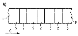
図1Aには、電気的にポンピングされる半導体チップ1の実施例が概略的な断面図で示されている。有利にはエピタキシャルに成長された半導体チップ1は、p型端子側p及びn型端子側nを有している。半導体チップ1の所定の動作時に、p型端子側pには正の電圧が印加され、n型端子側nにはp型端子側に相対的な負の電圧が印加される。電子のような負の電荷は、半導体チップ1の動作時に、n型端子側nからp型端子側pへと移動し、正孔のような正の電荷は、p型端子側pからn型端子側nへと移動する。電荷はそれぞれ、p型端子側p及びn型端子側nを介して半導体チップ1に注入される。 In FIG. 1A, an embodiment of an electrically pumped semiconductor chip 1 is shown in schematic cross-section. The epitaxially grown semiconductor chip 1 has a p-type terminal side p and an n-type terminal side n. During a predetermined operation of the semiconductor chip 1, a positive voltage is applied to the p-type terminal side p, and a relative negative voltage is applied to the n-type terminal side n on the p-type terminal side. Negative charges such as electrons move from the n-type terminal side n to the p-type terminal side p during the operation of the semiconductor chip 1, and positive charges such as holes move from the p-type terminal side p to the n-type. Move to terminal side n. The charges are respectively injected into the semiconductor chip 1 through the p-type terminal side p and the n-type terminal side n.
半導体チップ1は複数のビーム活性量子井戸2を有している。半導体チップ1の動作時には、ビーム活性量子井戸2において電荷の再結合によって電磁ビームが生成される。p型端子側pの方向に向かって、即ち、例えば成長方向Gの方向に見て、ビーム活性量子井戸2がそれぞれカバー層4の後ろに配置されている。カバー層4は0.2nm以上0.5nm以下、有利には約0.5nmの厚さTを有している。カバー層4は実質的にAlGaNから構成されており、カバー層4は異種原子の形態のドーパントを含有することができる。カバー層4における異種原子の割合は有利には最大で0.01原子%である。
The semiconductor chip 1 has a plurality of beam
ビーム活性量子井戸2の厚さQは例えば1.5nm以上4.5nm以下、特に約3.5nmである。量子井戸2はInGaNから構成されている。インジウム含有率は有利には15%以上35%以下である。換言すれば、ガリウム格子サイトの15%以上35%以下の部分がインジウム原子によって占められている。
The thickness Q of the beam active
成長方向Gに沿って、カバー層4とビーム活性量子井戸2との間にはそれぞれバリア層5が設けられている。バリア層5は有利にはGaNから構成されている。バリア層5も異種原子の形態のドーパントを含有することができる。
Barrier layers 5 are respectively provided between the
隣り合う二つのカバー層4の間隔Dは有利には3nm以上8nm以下、特に約6nmである。カバー層4のアルミニウム含有率は、図1Aの実施例においては、例えば20%以上50%以下である。
The distance D between two adjacent cover layers 4 is preferably not less than 3 nm and not more than 8 nm, in particular approximately 6 nm. In the embodiment of FIG. 1A, the aluminum content of the
図1Bには、バンドギャップEGの経過が成長方向Gに沿って図示されている。ビーム活性量子井戸2の領域においては、バンドギャップEGが例えば約2.55eVである。カバー層4の領域においては、バンドギャップEGが有利には約3.4eVである。従って、カバー層4によってバンドギャップEGが局所的に上昇し、ビーム活性量子井戸2のp型端子側pに対向しているp側における価電子帯及び伝導帯の構造に一種の歪みが生じている。p側におけるビーム活性量子井戸2の外側のバンドギャップEGは、n型端子側nに対向しているn側におけるビーム活性量子井戸2の外側のバンドギャップEGを上回っている。バンドギャップ構造のこの歪みによって、正孔の移動度が高まる。
The FIG. 1B, the course of the band gap E G are shown along the growth direction G. In the region of the beam active quantum well 2, the band gap E G is, for example, about 2.55 eV. In the region of the
これによって、特に全てのビーム活性量子井戸2がビームの放出に寄与することが達成される。量子井戸2のうちp型端子側pの一番近くに設けられている量子井戸2は割合的に見て一番多くのビームを放出し、これに対して、量子井戸2のうちn型端子側nの一番近くに設けられている量子井戸2は割合的に見て一番少ないビームを放出する。ビーム活性量子井戸2の各々は、有利には、半導体チップ1によって生成されるビーム出力全体の少なくとも2.5%を放出する。
This achieves in particular that all the beam
図2には、従来のオプトエレクトロニクス半導体構成素子が図示されており、図2Aにおいてはその断面図が示されており、また、図2Bにおいてはバンドギャップ構造が示されている。半導体構成素子は、成長方向Gに見て、バリア層5と量子井戸2とが順に配置されている。特に、図2による半導体構成素子においてはカバー層4が設けられていないので、量子井戸2しかビームの放出に寄与しないことが考えられる。
FIG. 2 shows a conventional optoelectronic semiconductor component, in which FIG. 2A shows a cross-sectional view and FIG. 2B shows a bandgap structure. In the semiconductor component, the
バンドギャップEGの構造は量子井戸2のp側におけるバンドギャップの上昇を示さない。それどころかむしろ、p側におけるバンドギャップEGは量子井戸2のn側に比べて低下している。
Structure of the band gap E G does not show an increase in band gap in the p-side of the
図3による半導体チップ1の実施例においては、ビーム活性量子井戸2a−2cと、それぞれの所属のカバー層4との間にはそれぞれ一つの中間層3が設けられている。中間層3はGaNから構成されており、また量子井戸2、カバー層4及びバリア層5と同様に異種原子のドーパントを含有することができる。中間層3の厚さは有利には1nmを下回っている。特に、厚さは約0.5nmである。図3による半導体チップ1におけるカバー層4のアルミニウム含有率は、有利には40%以上70%以下である。
In the embodiment of the semiconductor chip 1 according to FIG. 3, one
半導体チップ1は有利には、一連の層群8を3個以上20個以下有している。一連の層群8は、別の中間層を必要とすることなく、それぞれ相互に直接的に接触している。各層群8は、一つのビーム活性量子井戸2a−2c、一つの中間層3、一つのカバー層4及び一つのバリア層5から構成されている。上記の層は上記の順序で、別の中間層を必要とすることなく、相互に直接的に接触している。
The semiconductor chip 1 advantageously has a series of
他の全ての実施例と同様に、ビーム活性量子井戸2a−2cは半導体チップ1の動作時に、相互に異なる波長λ1,λ2,λ3を有しているビームをそれぞれ生成することができる。例えば、波長λ1は約440nmであり、波長λ2は約450nmであり、また、波長λ3は約465nmである。ここで波長とは、特に、半導体チップ1の動作時に最大スペクトル電力密度が放出される波長であると解される。
As in all other embodiments, the beam
図4aにおいては、例えば図1の実施例と同様に構成することができる半導体チップ1の別の実施例の概略的な断面図が示されている。図4Bには、特に図3に類似する半導体チップ1の詳細図が示されている。 FIG. 4a shows a schematic cross-sectional view of another embodiment of the semiconductor chip 1 which can be constructed, for example, in the same way as the embodiment of FIG. FIG. 4B shows a detailed view of a semiconductor chip 1 particularly similar to FIG.
半導体チップ1は成長方向Gに沿って一連の単層9を有している。単層9は成長方向Gに対して垂直な方向に延在しており、また、それぞれの単層9内に存在する原子のそれぞれの平均原子直径の厚さを有している。図4A及び図4Bにおいては、破線によって相互に境界付けられている複数の単層9が半導体チップ1の領域よってシンボリックに表されている。 The semiconductor chip 1 has a series of single layers 9 along the growth direction G. The single layer 9 extends in a direction perpendicular to the growth direction G, and has a thickness of each average atomic diameter of atoms present in each single layer 9. In FIG. 4A and FIG. 4B, a plurality of single layers 9 that are bounded by broken lines are symbolically represented by the region of the semiconductor chip 1.
ビーム活性量子井戸2とカバー層4との間には移行領域24が設けられている(図4Aを参照されたい)。移行領域24内には、ビーム活性量子井戸2の材料組成に対応する材料組成を有しているサブ領域が存在している。同様に、カバー層4の材料組成に対応する材料組成を有している別のサブ領域も存在している。図4Aによれば、移行領域24の厚さは単層二つ分の厚さである。
A
図4Bによる実施例においては、移行領域23,24がビーム活性量子井戸2と中間層3との間、並びに、中間層3とカバー層4との間において、単層一つ分の厚さをそれぞれ有している。図4A及び4Bに示されているものとは異なり、移行領域23,24,34が単層一つ分以上単層三つ分以下の有利な厚さを示しても良い。移行領域23,24,34の厚さは、例えば、透過型電子顕微鏡(略してTEM)を介して測定することができる。
In the embodiment according to FIG. 4B, the
また全ての実施例において、半導体チップ1が図示していない一つ又は複数の層を有することができる。その種の層として、トンネル層又はトンネル移行部、及び/又は、電荷阻止層、及び/又は、ビーム不活性量子井戸、及び/又は、電気的なコンタクト層、及び/又は、クラッド層、及び/又は、光導波層が考えられる。同様に、ビーム活性量子井戸2はそれぞれ成長方向Gに沿って、可変のインジウム含有率を有することができる。つまり、ビーム活性量子井戸2は、インジウム含有率がそれぞれ相互に異なっている、図示していない複数の部分層を有することができる。
In all embodiments, the semiconductor chip 1 can have one or more layers not shown. Such layers include tunnel layers or tunnel transitions and / or charge blocking layers and / or beam inert quantum wells and / or electrical contact layers and / or cladding layers, and / or Alternatively, an optical waveguide layer is conceivable. Similarly, each of the beam
ビーム活性量子井戸2の数は、例えば、半導体チップ1から放出されるビームの、半導体チップ1に供給される電流の電流強度に対する波長シフトを求めることによって証明することができる。波長シフトが大きくなればなるほど、ビーム活性量子井戸の数が少なくなる。同様に、半導体チップ1を駆動させる電流の電流強度に対する、ビーム活性量子井戸の内部量子効率の検出を介して、ビーム活性量子井戸の数を求めることができる。
The number of beam
上記において説明した本発明は、実施例に基づいた上記の説明によって限定されるものではない。むしろ本発明はあらゆる新規の特徴ならびにそれらの特徴のあらゆる組み合わせを含むものであり、これには殊に特許請求の範囲に記載した特徴の組み合わせ各々が含まれ、このことはそのような組み合わせ自体が特許請求の範囲あるいは実施例に明示的には記載されていないにしても当てはまる。 The present invention described above is not limited by the above description based on the embodiments. Rather, the invention includes any novel features and combinations of those features, particularly including each of the combinations of features recited in the claims, as such a combination itself. This applies even if not explicitly stated in the claims or the examples.
本願は、ドイツ連邦共和国特許出願第10 2009 037 416.7号の優先権を主張するものであり、その開示内容は参照により本願に取り入れられる。 This application claims priority from German Patent Application No. 10 2009 037 416.7, the disclosure of which is incorporated herein by reference.
Claims (12)
InGaNを含有しているか、又は、InGaNから構成されている、少なくとも二つのビーム活性量子井戸(2)と、
AlGaNを含有しているか、又は、AlGaNから構成されている、少なくとも二つのカバー層(4)とを有しており、
前記カバー層(4)はそれぞれ、前記ビーム活性量子井戸(2)のうちの一つに対応付けられており、
前記カバー層(4)は前記ビーム活性量子井戸(2)のp側にそれぞれ設けられており、
前記ビーム活性量子井戸(2)と、対応付けられている前記カバー層(4)との間隔は最大で1.5nmであり、
一連の層群(8)が3回から20回繰り返されて設けられており、
隣接する一連の層群(8)は直接的に重なって設けられており、
前記一連の層群(8)は、
−ビーム活性量子井戸(2)、
−GaNを含有しているか、又は、GaNから構成されている中間層(3)、
−カバー層(4)、
−GaNを含有しているか、又は、GaNから構成されているバリア層(5)、
の順序で直接的に相互に重なって設けられている複数の層から構成されており、
更に、前記カバー層(4)の平均厚さは0.3nm以上1.5nm以下であり、前記中間層(3)の厚さは0.3nm以上1.2nm以下であり、成長方向における連続する二つのカバー層(4)の間隔は3nm以上8nm以下であり、
前記カバー層(4)は、Al x Ga 1−x Nからなり、但し、0.2≦x≦0.7である、
ことを特徴とする、オプトエレクトロニクス半導体チップ(1)。 In an electrically pumped optoelectronic semiconductor chip (1),
At least two beam active quantum wells (2) containing or composed of InGaN; and
Comprising at least two cover layers (4) containing AlGaN or composed of AlGaN;
Each of the cover layers (4) is associated with one of the beam active quantum wells (2);
The cover layer (4) is provided on the p side of the beam active quantum well (2), respectively.
The distance between the beam active quantum well (2) and the associated cover layer (4) is at most 1.5 nm,
A series of layer groups (8) is provided 3 to 20 times repeated,
A series of adjacent layer groups (8) are directly overlapped,
The series of layer groups (8)
-Beam active quantum well (2),
An intermediate layer (3) containing or consisting of GaN,
-Cover layer (4),
A barrier layer (5) containing or composed of GaN,
It is composed of a plurality of layers that are directly overlapped with each other in the order of
Furthermore, the average thickness of the cover layer (4) is not less than 0.3 nm and not more than 1.5 nm, and the thickness of the intermediate layer (3) is not less than 0.3 nm and not more than 1.2 nm, and is continuous in the growth direction. spacing of the two cover layers (4) Ri der than 8nm or less 3 nm,
The cover layer (4) is made of Al x Ga 1-x N, provided that 0.2 ≦ x ≦ 0.7.
An optoelectronic semiconductor chip (1) characterized in that
In y Ga 1−y Nから構成されている前記ビーム活性量子井戸(2)のインジウム含有率yは0.15≦y≦0.35である、請求項1乃至3のいずれか一項に記載のオプトエレクトロニクス半導体チップ(1)。 The beam active quantum well (2) has a thickness (Q) of 1.5 nm to 4.5 nm,
An In y Ga indium content y of 1-y wherein and an N-beam active quantum well (2) is 0.15 ≦ y ≦ 0.35, according to any one of claims 1 to 3 Optoelectronic semiconductor chip (1).
前記カバー層(4)のAl含有率xは0.2≦x≦0.5である、請求項1乃至5のいずれか一項に記載のオプトエレクトロニクス半導体チップ(1)。 The distance between the beam active quantum well (2) and the cover layer (4) associated with the beam active quantum well (2) is at most a thickness of two single layers,
The optoelectronic semiconductor chip (1) according to any one of claims 1 to 5, wherein the Al content x of the cover layer (4) is 0.2≤x≤0.5 .
該ビーム活性量子井戸(2)の単層と、AlGaNしか含有していない前記カバー層(4)の単層との間には、InGaN及び/又はGaN及び/又はAlGaNから成る混合物を含有する、最大で二つの単層が存在する、請求項6記載のオプトエレクトロニクス半導体チップ(1)。 The beam active quantum well (2) contains only InGaN,
Between the single layer of the beam active quantum well (2) and the single layer of the cover layer (4) containing only AlGaN, a mixture comprising InGaN and / or GaN and / or AlGaN is contained. 7. The optoelectronic semiconductor chip (1) according to claim 6 , wherein there are at most two monolayers.
前記偏差は0.03eV以上0.20eV以下である、請求項1乃至11のいずれか一項に記載のオプトエレクトロニクス半導体チップ(1)。 At least two adjacent beam active quantum wells (2) exhibit an average band gap deviating from each other;
The optoelectronic semiconductor chip (1) according to any one of claims 1 to 11 , wherein the deviation is not less than 0.03 eV and not more than 0.20 eV.
Applications Claiming Priority (3)
| Application Number | Priority Date | Filing Date | Title |
|---|---|---|---|
| DE102009037416.7 | 2009-08-13 | ||
| DE102009037416.7A DE102009037416B4 (en) | 2009-08-13 | 2009-08-13 | Electrically pumped optoelectronic semiconductor chip |
| PCT/EP2010/059291 WO2011018273A1 (en) | 2009-08-13 | 2010-06-30 | Electrically pumped optoelectronic semiconductor chip |
Publications (3)
| Publication Number | Publication Date |
|---|---|
| JP2013502058A JP2013502058A (en) | 2013-01-17 |
| JP2013502058A5 JP2013502058A5 (en) | 2013-04-04 |
| JP5705222B2 true JP5705222B2 (en) | 2015-04-22 |
Family
ID=42711811
Family Applications (1)
| Application Number | Title | Priority Date | Filing Date |
|---|---|---|---|
| JP2012524169A Active JP5705222B2 (en) | 2009-08-13 | 2010-06-30 | Electrically pumped optoelectronic semiconductor chip |
Country Status (7)
| Country | Link |
|---|---|
| US (1) | US8581236B2 (en) |
| EP (1) | EP2465148B1 (en) |
| JP (1) | JP5705222B2 (en) |
| KR (2) | KR101733149B1 (en) |
| CN (1) | CN102576785B (en) |
| DE (1) | DE102009037416B4 (en) |
| WO (1) | WO2011018273A1 (en) |
Families Citing this family (5)
| Publication number | Priority date | Publication date | Assignee | Title |
|---|---|---|---|---|
| WO2012012010A2 (en) | 2010-04-30 | 2012-01-26 | Trustees Of Boston University | High efficiency ultraviolet light emitting diode with band structure potential fluctuations |
| US8723189B1 (en) | 2012-01-06 | 2014-05-13 | Trustees Of Boston University | Ultraviolet light emitting diode structures and methods of manufacturing the same |
| DE102013200507A1 (en) * | 2013-01-15 | 2014-07-17 | Osram Opto Semiconductors Gmbh | Optoelectronic semiconductor component |
| JP6010088B2 (en) * | 2014-11-07 | 2016-10-19 | 株式会社東芝 | Semiconductor light emitting device |
| JP2022172792A (en) * | 2021-05-07 | 2022-11-17 | 日機装株式会社 | Nitride semiconductor light emitting device |
Family Cites Families (19)
| Publication number | Priority date | Publication date | Assignee | Title |
|---|---|---|---|---|
| US5023685A (en) * | 1988-06-06 | 1991-06-11 | Bethea Clyde G | Quantum-well radiation-interactive device, and methods of radiation detection and modulation |
| JP3304782B2 (en) * | 1996-09-08 | 2002-07-22 | 豊田合成株式会社 | Semiconductor light emitting device |
| JP3705047B2 (en) * | 1998-12-15 | 2005-10-12 | 日亜化学工業株式会社 | Nitride semiconductor light emitting device |
| DE19955747A1 (en) | 1999-11-19 | 2001-05-23 | Osram Opto Semiconductors Gmbh | Optical semiconductor device with multiple quantum well structure, e.g. LED, has alternate well layers and barrier layers forming super-lattices |
| JP4032636B2 (en) * | 1999-12-13 | 2008-01-16 | 日亜化学工業株式会社 | Light emitting element |
| US6586762B2 (en) * | 2000-07-07 | 2003-07-01 | Nichia Corporation | Nitride semiconductor device with improved lifetime and high output power |
| US6906352B2 (en) | 2001-01-16 | 2005-06-14 | Cree, Inc. | Group III nitride LED with undoped cladding layer and multiple quantum well |
| WO2002103814A1 (en) * | 2001-06-15 | 2002-12-27 | Cree, Inc. | Gan based led formed on a sic substrate |
| JP2004289112A (en) * | 2003-03-06 | 2004-10-14 | Ricoh Co Ltd | Semiconductor light emitting element, its manufacturing method, optical transmitting module, optical transmitting/receiving module, and optical communication system |
| US6927412B2 (en) | 2002-11-21 | 2005-08-09 | Ricoh Company, Ltd. | Semiconductor light emitter |
| EP1667292B1 (en) | 2003-08-26 | 2010-11-03 | Sony Corporation | GaN III-V COMPOUND SEMICONDUCTOR LIGHT-EMITTING DEVICE AND METHOD FOR MANUFACTURING SAME |
| JP2006108585A (en) | 2004-10-08 | 2006-04-20 | Toyoda Gosei Co Ltd | Group III nitride compound semiconductor light emitting device |
| JP2006210692A (en) * | 2005-01-28 | 2006-08-10 | Toyoda Gosei Co Ltd | Group iii nitride compound semiconductor light emitting device |
| JP2006332258A (en) * | 2005-05-25 | 2006-12-07 | Matsushita Electric Ind Co Ltd | Nitride semiconductor device and manufacturing method thereof |
| EP1764840A1 (en) * | 2005-09-15 | 2007-03-21 | SuperNova Optoelectronics Corporation | Gallium nitride semiconductor light emitting device |
| EP1883141B1 (en) | 2006-07-27 | 2017-05-24 | OSRAM Opto Semiconductors GmbH | LD or LED with superlattice cladding layer |
| CA2662526C (en) * | 2006-09-01 | 2015-12-22 | Georgia State University Research Foundation Inc. | High operation temperature split-off band infrared detectors |
| KR101330898B1 (en) * | 2007-04-05 | 2013-11-18 | 엘지전자 주식회사 | Semiconductor laser diode |
| US20090183774A1 (en) * | 2007-07-13 | 2009-07-23 | Translucent, Inc. | Thin Film Semiconductor-on-Sapphire Solar Cell Devices |
-
2009
- 2009-08-13 DE DE102009037416.7A patent/DE102009037416B4/en active Active
-
2010
- 2010-06-30 CN CN201080035921.1A patent/CN102576785B/en active Active
- 2010-06-30 KR KR1020167033319A patent/KR101733149B1/en active Active
- 2010-06-30 KR KR1020127006584A patent/KR101682345B1/en active Active
- 2010-06-30 WO PCT/EP2010/059291 patent/WO2011018273A1/en active Application Filing
- 2010-06-30 US US13/383,495 patent/US8581236B2/en active Active
- 2010-06-30 JP JP2012524169A patent/JP5705222B2/en active Active
- 2010-06-30 EP EP10726134.9A patent/EP2465148B1/en active Active
Also Published As
| Publication number | Publication date |
|---|---|
| CN102576785A (en) | 2012-07-11 |
| KR101733149B1 (en) | 2017-05-08 |
| DE102009037416A1 (en) | 2011-02-17 |
| EP2465148B1 (en) | 2017-08-09 |
| DE102009037416B4 (en) | 2021-10-14 |
| JP2013502058A (en) | 2013-01-17 |
| KR20160142890A (en) | 2016-12-13 |
| KR101682345B1 (en) | 2016-12-05 |
| WO2011018273A1 (en) | 2011-02-17 |
| CN102576785B (en) | 2015-05-20 |
| US8581236B2 (en) | 2013-11-12 |
| US20120161103A1 (en) | 2012-06-28 |
| EP2465148A1 (en) | 2012-06-20 |
| KR20120045049A (en) | 2012-05-08 |
Similar Documents
| Publication | Publication Date | Title |
|---|---|---|
| JP4163192B2 (en) | Nitride semiconductor device | |
| JP4875455B2 (en) | Nitride semiconductor light emitting device | |
| KR101466674B1 (en) | Radiation-emitting semiconductor body | |
| JP5259660B2 (en) | Semiconductor light emitting device | |
| EP2532059A2 (en) | High injection efficiency polar and non-polar iii-nitrides light emitters | |
| JP5705222B2 (en) | Electrically pumped optoelectronic semiconductor chip | |
| JP6113363B2 (en) | Optoelectronic semiconductor chip with multiple quantum wells having at least one high barrier layer | |
| US9356428B2 (en) | Nitride semiconductor surface emitting laser and method of manufacturing the same | |
| TW201351689A (en) | Semiconductor light emitting structure | |
| TW200919883A (en) | Opto-electronic semiconductor chip with quantum-well structure | |
| KR20130141945A (en) | Light emitting device having electron blocking layer | |
| KR101211657B1 (en) | nitride semiconductor light emitting device | |
| US9634184B2 (en) | Optoelectronic semiconductor device | |
| JP2000349397A (en) | Semiconductor light emitting device | |
| US8022392B2 (en) | Semiconductor layer structure with superlattice | |
| KR100558455B1 (en) | Nitride semiconductor devices | |
| US10218152B1 (en) | Semiconductor laser diode with low threshold current | |
| JP2019160974A (en) | Semiconductor light-emitting element | |
| JP2009158831A (en) | Semiconductor light emitting element | |
| JP2016066670A (en) | Semiconductor laser | |
| US11056857B2 (en) | Laser diode | |
| JP5229128B2 (en) | Semiconductor light emitting device | |
| WO2007026767A1 (en) | Light-emitting element and method for fabricating same | |
| TWI440216B (en) | Photoelectric semiconductor body with quantum well structure | |
| JPWO2016157739A1 (en) | Semiconductor light emitting device |
Legal Events
| Date | Code | Title | Description |
|---|---|---|---|
| A521 | Request for written amendment filed |
Free format text: JAPANESE INTERMEDIATE CODE: A523 Effective date: 20130214 |
|
| A621 | Written request for application examination |
Free format text: JAPANESE INTERMEDIATE CODE: A621 Effective date: 20130214 |
|
| A977 | Report on retrieval |
Free format text: JAPANESE INTERMEDIATE CODE: A971007 Effective date: 20131226 |
|
| A131 | Notification of reasons for refusal |
Free format text: JAPANESE INTERMEDIATE CODE: A131 Effective date: 20140310 |
|
| A601 | Written request for extension of time |
Free format text: JAPANESE INTERMEDIATE CODE: A601 Effective date: 20140603 |
|
| A602 | Written permission of extension of time |
Free format text: JAPANESE INTERMEDIATE CODE: A602 Effective date: 20140610 |
|
| A521 | Request for written amendment filed |
Free format text: JAPANESE INTERMEDIATE CODE: A523 Effective date: 20140828 |
|
| TRDD | Decision of grant or rejection written | ||
| A01 | Written decision to grant a patent or to grant a registration (utility model) |
Free format text: JAPANESE INTERMEDIATE CODE: A01 Effective date: 20150202 |
|
| A61 | First payment of annual fees (during grant procedure) |
Free format text: JAPANESE INTERMEDIATE CODE: A61 Effective date: 20150224 |
|
| R150 | Certificate of patent or registration of utility model |
Ref document number: 5705222 Country of ref document: JP Free format text: JAPANESE INTERMEDIATE CODE: R150 |
|
| R250 | Receipt of annual fees |
Free format text: JAPANESE INTERMEDIATE CODE: R250 |
|
| R250 | Receipt of annual fees |
Free format text: JAPANESE INTERMEDIATE CODE: R250 |
|
| R250 | Receipt of annual fees |
Free format text: JAPANESE INTERMEDIATE CODE: R250 |
|
| R250 | Receipt of annual fees |
Free format text: JAPANESE INTERMEDIATE CODE: R250 |
|
| R250 | Receipt of annual fees |
Free format text: JAPANESE INTERMEDIATE CODE: R250 |
|
| R250 | Receipt of annual fees |
Free format text: JAPANESE INTERMEDIATE CODE: R250 |
|
| R250 | Receipt of annual fees |
Free format text: JAPANESE INTERMEDIATE CODE: R250 |