JP5699227B2 - Power transmission device - Google Patents
Power transmission device Download PDFInfo
- Publication number
- JP5699227B2 JP5699227B2 JP2013547173A JP2013547173A JP5699227B2 JP 5699227 B2 JP5699227 B2 JP 5699227B2 JP 2013547173 A JP2013547173 A JP 2013547173A JP 2013547173 A JP2013547173 A JP 2013547173A JP 5699227 B2 JP5699227 B2 JP 5699227B2
- Authority
- JP
- Japan
- Prior art keywords
- speed change
- change mechanism
- rotation axis
- transmission mechanism
- rotation
- Prior art date
- Legal status (The legal status is an assumption and is not a legal conclusion. Google has not performed a legal analysis and makes no representation as to the accuracy of the status listed.)
- Active
Links
- 230000005540 biological transmission Effects 0.000 title claims description 265
- 230000007246 mechanism Effects 0.000 claims description 458
- 230000008859 change Effects 0.000 claims description 228
- 238000005192 partition Methods 0.000 claims description 27
- 230000002093 peripheral effect Effects 0.000 claims description 14
- 230000008878 coupling Effects 0.000 claims 1
- 238000010168 coupling process Methods 0.000 claims 1
- 238000005859 coupling reaction Methods 0.000 claims 1
- 239000003638 chemical reducing agent Substances 0.000 description 59
- 239000000969 carrier Substances 0.000 description 20
- 238000010586 diagram Methods 0.000 description 14
- 230000001133 acceleration Effects 0.000 description 12
- 230000001172 regenerating effect Effects 0.000 description 11
- 238000006243 chemical reaction Methods 0.000 description 8
- 230000009467 reduction Effects 0.000 description 5
- 238000002485 combustion reaction Methods 0.000 description 2
- 230000006872 improvement Effects 0.000 description 1
- 230000006698 induction Effects 0.000 description 1
- 238000004519 manufacturing process Methods 0.000 description 1
- 238000000926 separation method Methods 0.000 description 1
- 230000009466 transformation Effects 0.000 description 1
Images


Classifications
-
- B—PERFORMING OPERATIONS; TRANSPORTING
- B60—VEHICLES IN GENERAL
- B60K—ARRANGEMENT OR MOUNTING OF PROPULSION UNITS OR OF TRANSMISSIONS IN VEHICLES; ARRANGEMENT OR MOUNTING OF PLURAL DIVERSE PRIME-MOVERS IN VEHICLES; AUXILIARY DRIVES FOR VEHICLES; INSTRUMENTATION OR DASHBOARDS FOR VEHICLES; ARRANGEMENTS IN CONNECTION WITH COOLING, AIR INTAKE, GAS EXHAUST OR FUEL SUPPLY OF PROPULSION UNITS IN VEHICLES
- B60K1/00—Arrangement or mounting of electrical propulsion units
- B60K1/02—Arrangement or mounting of electrical propulsion units comprising more than one electric motor
-
- B—PERFORMING OPERATIONS; TRANSPORTING
- B60—VEHICLES IN GENERAL
- B60K—ARRANGEMENT OR MOUNTING OF PROPULSION UNITS OR OF TRANSMISSIONS IN VEHICLES; ARRANGEMENT OR MOUNTING OF PLURAL DIVERSE PRIME-MOVERS IN VEHICLES; AUXILIARY DRIVES FOR VEHICLES; INSTRUMENTATION OR DASHBOARDS FOR VEHICLES; ARRANGEMENTS IN CONNECTION WITH COOLING, AIR INTAKE, GAS EXHAUST OR FUEL SUPPLY OF PROPULSION UNITS IN VEHICLES
- B60K17/00—Arrangement or mounting of transmissions in vehicles
- B60K17/34—Arrangement or mounting of transmissions in vehicles for driving both front and rear wheels, e.g. four wheel drive vehicles
- B60K17/356—Arrangement or mounting of transmissions in vehicles for driving both front and rear wheels, e.g. four wheel drive vehicles having fluid or electric motor, for driving one or more wheels
-
- B—PERFORMING OPERATIONS; TRANSPORTING
- B60—VEHICLES IN GENERAL
- B60K—ARRANGEMENT OR MOUNTING OF PROPULSION UNITS OR OF TRANSMISSIONS IN VEHICLES; ARRANGEMENT OR MOUNTING OF PLURAL DIVERSE PRIME-MOVERS IN VEHICLES; AUXILIARY DRIVES FOR VEHICLES; INSTRUMENTATION OR DASHBOARDS FOR VEHICLES; ARRANGEMENTS IN CONNECTION WITH COOLING, AIR INTAKE, GAS EXHAUST OR FUEL SUPPLY OF PROPULSION UNITS IN VEHICLES
- B60K17/00—Arrangement or mounting of transmissions in vehicles
- B60K17/04—Arrangement or mounting of transmissions in vehicles characterised by arrangement, location or kind of gearing
- B60K17/043—Transmission unit disposed in on near the vehicle wheel, or between the differential gear unit and the wheel
- B60K17/046—Transmission unit disposed in on near the vehicle wheel, or between the differential gear unit and the wheel with planetary gearing having orbital motion
-
- B—PERFORMING OPERATIONS; TRANSPORTING
- B60—VEHICLES IN GENERAL
- B60K—ARRANGEMENT OR MOUNTING OF PROPULSION UNITS OR OF TRANSMISSIONS IN VEHICLES; ARRANGEMENT OR MOUNTING OF PLURAL DIVERSE PRIME-MOVERS IN VEHICLES; AUXILIARY DRIVES FOR VEHICLES; INSTRUMENTATION OR DASHBOARDS FOR VEHICLES; ARRANGEMENTS IN CONNECTION WITH COOLING, AIR INTAKE, GAS EXHAUST OR FUEL SUPPLY OF PROPULSION UNITS IN VEHICLES
- B60K7/00—Disposition of motor in, or adjacent to, traction wheel
- B60K7/0007—Disposition of motor in, or adjacent to, traction wheel the motor being electric
-
- F—MECHANICAL ENGINEERING; LIGHTING; HEATING; WEAPONS; BLASTING
- F16—ENGINEERING ELEMENTS AND UNITS; GENERAL MEASURES FOR PRODUCING AND MAINTAINING EFFECTIVE FUNCTIONING OF MACHINES OR INSTALLATIONS; THERMAL INSULATION IN GENERAL
- F16H—GEARING
- F16H3/00—Toothed gearings for conveying rotary motion with variable gear ratio or for reversing rotary motion
- F16H3/44—Toothed gearings for conveying rotary motion with variable gear ratio or for reversing rotary motion using gears having orbital motion
-
- B—PERFORMING OPERATIONS; TRANSPORTING
- B60—VEHICLES IN GENERAL
- B60K—ARRANGEMENT OR MOUNTING OF PROPULSION UNITS OR OF TRANSMISSIONS IN VEHICLES; ARRANGEMENT OR MOUNTING OF PLURAL DIVERSE PRIME-MOVERS IN VEHICLES; AUXILIARY DRIVES FOR VEHICLES; INSTRUMENTATION OR DASHBOARDS FOR VEHICLES; ARRANGEMENTS IN CONNECTION WITH COOLING, AIR INTAKE, GAS EXHAUST OR FUEL SUPPLY OF PROPULSION UNITS IN VEHICLES
- B60K7/00—Disposition of motor in, or adjacent to, traction wheel
- B60K2007/0046—Disposition of motor in, or adjacent to, traction wheel the motor moving together with the vehicle body, i.e. moving independently from the wheel axle
-
- B—PERFORMING OPERATIONS; TRANSPORTING
- B60—VEHICLES IN GENERAL
- B60K—ARRANGEMENT OR MOUNTING OF PROPULSION UNITS OR OF TRANSMISSIONS IN VEHICLES; ARRANGEMENT OR MOUNTING OF PLURAL DIVERSE PRIME-MOVERS IN VEHICLES; AUXILIARY DRIVES FOR VEHICLES; INSTRUMENTATION OR DASHBOARDS FOR VEHICLES; ARRANGEMENTS IN CONNECTION WITH COOLING, AIR INTAKE, GAS EXHAUST OR FUEL SUPPLY OF PROPULSION UNITS IN VEHICLES
- B60K7/00—Disposition of motor in, or adjacent to, traction wheel
- B60K2007/0092—Disposition of motor in, or adjacent to, traction wheel the motor axle being coaxial to the wheel axle
-
- B—PERFORMING OPERATIONS; TRANSPORTING
- B60—VEHICLES IN GENERAL
- B60Y—INDEXING SCHEME RELATING TO ASPECTS CROSS-CUTTING VEHICLE TECHNOLOGY
- B60Y2400/00—Special features of vehicle units
- B60Y2400/42—Clutches or brakes
- B60Y2400/427—One-way clutches
Landscapes
- Engineering & Computer Science (AREA)
- Mechanical Engineering (AREA)
- Chemical & Material Sciences (AREA)
- Combustion & Propulsion (AREA)
- Transportation (AREA)
- General Engineering & Computer Science (AREA)
- Retarders (AREA)
- Structure Of Transmissions (AREA)
- Arrangement And Driving Of Transmission Devices (AREA)
- Hybrid Electric Vehicles (AREA)
- Arrangement Or Mounting Of Propulsion Units For Vehicles (AREA)
Description
本発明は、第1駆動源の出力軸に接続される第1変速機構と、第2駆動源に接続される第2変速機構と、を備える動力伝達装置に関する。 The present invention relates to a power transmission device including a first transmission mechanism connected to an output shaft of a first drive source and a second transmission mechanism connected to a second drive source.
このような動力伝達装置として、特許文献1には、第1変速機構と第2変速機構とが遊星歯車機構で構成され、互いのリングギヤ同士が相対回転不能に連結された構成が開示されている。リングギヤがプラネタリギヤと噛み合う際、リングギヤには軸方向にスラスト力が作用するが、特許文献1では、この点に対し何ら言及がなされていない。 As such a power transmission device, Patent Document 1 discloses a configuration in which a first transmission mechanism and a second transmission mechanism are configured by a planetary gear mechanism, and the ring gears are connected so as not to be relatively rotatable. . When the ring gear meshes with the planetary gear, a thrust force acts on the ring gear in the axial direction. However, in Patent Document 1, no reference is made to this point.
これに対し、特許文献2では、2段ピニオンの大径ギヤとアイドラギヤとの間に発生するスラスト力と、2段ピニオンの小径ギヤと駆動出力ギヤとの間に発生するスラスト力とを、対向する第1変速機構の2段ピニオンと第2変速機構の2段ピニオンとの間に配置されたスラスト軸受を介して相殺することが記載されている。 On the other hand, in Patent Document 2, the thrust force generated between the large-diameter gear of the two-stage pinion and the idler gear is opposed to the thrust force generated between the small-diameter gear of the two-stage pinion and the drive output gear. It cancels out via a thrust bearing disposed between the two-stage pinion of the first transmission mechanism and the two-stage pinion of the second transmission mechanism.
また、特許文献3に記載の動力伝達装置では、遊星歯車機構の2段ピニオンの大径ギヤで発生するスラスト力と2段ピニオンの小径ギヤで発生するスラスト力とを、2段ピニオン内で相殺することが記載されている。
Further, in the power transmission device described in
しかしながら、特許文献2に記載の動力伝達装置は、2段ピニオン同士でスラスト力をスラスト軸受で相殺するものであるため、2段ピニオン同士がスラスト軸受を介して軸方向に動力伝達可能である装置以外にはそのまま適用することができない。 However, since the power transmission device described in Patent Document 2 cancels the thrust force between the two-stage pinions with the thrust bearing, the two-stage pinions can transmit power in the axial direction via the thrust bearing. It cannot be applied as it is.
特許文献3に記載の動力伝達装置は、1つの遊星歯車機構内の2段ピニオンでスラスト力を相殺するものであり、2つの変速機構を備えた動力伝達装置では、他の部材との関係を考慮して更なるスラスト力の低減が望まれている。
The power transmission device described in
本発明は、上記課題に鑑みてなされたものであり、2つの変速機構を備え、スラスト力を低減することができる動力伝達装置を提供することを目的とする。 The present invention has been made in view of the above problems, and an object of the present invention is to provide a power transmission device that includes two transmission mechanisms and can reduce the thrust force.
上記の目的を達成するために、請求項1に記載の発明は、
第1駆動源(例えば、後述の実施形態の第1電動機2A)の出力軸(例えば、後述の実施形態の円筒軸16A)に接続される第1変速機構(例えば、後述の実施形態の第1遊星歯車式減速機12A)と、第2駆動源(例えば、後述の実施形態の第2電動機2B)の出力軸(例えば、後述の実施形態の円筒軸16B)に接続される第2変速機構(例えば、後述の実施形態の第2遊星歯車式減速機12B)と、を備え、前記第1変速機構と前記第2変速機構とは夫々複数の回転要素を有し、
前記第1変速機構の第1回転要素(例えば、後述の実施形態のリングギヤ24A)と、前記第2変速機構の第1回転要素(例えば、後述の実施形態のリングギヤ24B)とは、互いに一体回転可能に連結されて同一の回転軸線を有する動力伝達装置であって、
前記第1変速機構は、前記第1回転要素と噛合する第2回転要素(例えば、後述の実施形態のプラネタリギヤ22A)を備え、
該第1回転要素と、該第2回転要素との噛合部は、前記第1駆動源が一方向への回転トルクを発生するときに、前記第1変速機構の前記第1回転要素に、前記回転軸線方向で前記第2変速機構に近づく向きに力が働くように形成され、
前記第2変速機構は、前記第1回転要素と噛合する第2回転要素(例えば、後述の実施形態のプラネタリギヤ22B)を備え、
該第1回転要素と、該第2回転要素との噛合部は、前記第2駆動源が一方向への回転トルクを発生するときに、前記第2変速機構の前記第1回転要素に、前記回転軸線方向で前記第1変速機構に近づく向きに力が働くように形成され、
前記第1変速機構と前記第2変速機構とは、それぞれ遊星歯車機構であって、
前記遊星歯車機構は、サンギヤ(例えば、後述の実施形態のサンギヤ21A、21B)と、該サンギヤに噛合するプラネタリギヤ(例えば、後述の実施形態のプラネタリギヤ22A、22B)と、該プラネタリギヤを支持するプラネタリキャリア(例えば、後述の実施形態のプラネタリキャリア23A、23B)と、前記プラネタリギヤの外周側に噛合するリングギヤ(例えば、後述の実施形態のリングギヤ24A、24B)と、を備え、
前記第1回転要素は、前記リングギヤであり、
前記第2回転要素は、前記プラネタリギヤであることを特徴とする。
In order to achieve the above object, the invention described in claim 1
A first speed change mechanism (for example, a first shaft of an embodiment to be described later) connected to an output shaft (for example, a
A first rotation element of the first transmission mechanism (for example, a
The first speed change mechanism includes a second rotating element (for example, a
When the first drive source generates rotational torque in one direction, the meshing portion between the first rotational element and the second rotational element is connected to the first rotational element of the first transmission mechanism. Formed so that a force acts in a direction approaching the second speed change mechanism in the rotation axis direction;
The second speed change mechanism includes a second rotating element (for example, a
When the second drive source generates rotational torque in one direction, the meshing portion between the first rotational element and the second rotational element is connected to the first rotational element of the second transmission mechanism. Formed so that a force acts in a direction approaching the first speed change mechanism in the rotation axis direction ;
Each of the first transmission mechanism and the second transmission mechanism is a planetary gear mechanism,
The planetary gear mechanism includes a sun gear (for example,
The first rotating element is the ring gear;
The second rotating element, and wherein said planetary gear der Rukoto.
また、請求項2に記載の発明は、請求項1に記載の構成に加えて、
前記第1変速機構の前記第1回転要素と前記第2回転要素との噛合部は、前記第1駆動源が前記一方向への回転トルクを発生するときに、前記第1変速機構の前記第2回転要素に、前記回転軸線方向で前記第2変速機構から離れる向きに力が働くように形成され、
前記第2変速機構の前記第1回転要素と前記第2回転要素との噛合部は、前記第2駆動源が前記一方向への回転トルクを発生するときに、前記第2変速機構の前記第2回転要素に、前記回転軸線方向で前記第1変速機構から離れる向きに力が働くように形成され、
前記第1変速機構の前記第2回転要素に対し、前記回転軸線方向で前記第2変速機構とは反対側に、該第2回転要素に加わる前記回転軸線方向の力を受けることのできる第1軸受(例えば、後述の実施形態の軸受Br1)が配置され、
前記第2変速機構の前記第2回転要素に対し、前記回転軸線方向で前記第1変速機構とは反対側に、該第2回転要素に加わる前記回転軸線方向の力を受けることのできる第2軸受(例えば、後述の実施形態の軸受Br2)が配置されることを特徴とする。Moreover, in addition to the structure of Claim 1, the invention of Claim 2 is
The meshing portion between the first rotating element and the second rotating element of the first speed change mechanism is configured such that when the first drive source generates rotational torque in the one direction, the first speed change mechanism of the first speed change mechanism. The two-rotation element is formed such that a force acts in a direction away from the second transmission mechanism in the rotation axis direction,
The meshing portion between the first rotating element and the second rotating element of the second speed change mechanism is configured such that when the second drive source generates rotational torque in the one direction, the first speed of the second speed change mechanism is increased. A force is applied to the two rotating elements in a direction away from the first speed change mechanism in the direction of the rotation axis;
A first force capable of receiving a force in the direction of the rotation axis applied to the second rotation element on a side opposite to the second transmission mechanism in the rotation axis direction with respect to the second rotation element of the first transmission mechanism. A bearing (for example, a bearing Br1 in an embodiment described later) is disposed,
A second force capable of receiving a force in the direction of the rotation axis applied to the second rotation element on the side opposite to the first speed change mechanism in the rotation axis direction relative to the second rotation element of the second transmission mechanism. A bearing (for example, a bearing Br2 in an embodiment described later) is arranged.
また、請求項3に記載の発明は、請求項2に記載の構成に加えて、
前記第1変速機構は、前記第2回転要素と噛合する第3回転要素(例えば、後述の実施形態のサンギヤ21A)を備え、該第2回転要素と該第3回転要素との噛合部は、前記第1駆動源が前記一方向への回転トルクを発生するときに、前記第1変速機構の前記第3回転要素に、前記回転軸線方向で前記第2変速機構から離れる向きに力が働くように形成され、
前記第2変速機構は、前記第2回転要素と噛合する第3回転要素(例えば、後述の実施形態のサンギヤ21B)を備え、該第2回転要素と該第3回転要素との噛合部は、前記第2駆動源が前記一方向への回転トルクを発生するときに、前記第2変速機構の前記第3回転要素に、前記回転軸線方向で前記第1変速機構から離れる向きに力が働くように形成され、
前記第1変速機構の前記第3回転要素に対し、前記回転軸線方向で前記第2変速機構とは反対側に、該第3回転要素に加わる前記回転軸線方向の力を受けることのできる第3軸受(例えば、後述の実施形態の軸受Br3)が配置され、
前記第2変速機構の前記第3回転要素に対し、前記回転軸線方向で前記第1変速機構とは反対側に、該第3回転要素に加わる前記回転軸線方向の力を受けることのできる第4軸受(例えば、後述の実施形態の軸受Br4)が配置され、
前記第3回転要素は、前記サンギヤであることを特徴とする。
Moreover, in addition to the structure of Claim 2, the invention of
The first speed change mechanism includes a third rotating element (for example, a
The second speed change mechanism includes a third rotating element (for example, a
A third force that can receive a force in the direction of the rotation axis applied to the third rotation element on the side opposite to the second speed change mechanism in the direction of the rotation axis with respect to the third rotation element of the first transmission mechanism. A bearing (for example, a bearing Br3 in an embodiment described later) is disposed,
A fourth force capable of receiving a force in the direction of the rotation axis applied to the third rotation element on a side opposite to the first transmission mechanism in the rotation axis direction with respect to the third rotation element of the second transmission mechanism. A bearing (for example, a bearing Br4 in an embodiment described later) is disposed,
The third rotating element, and wherein the sun gear der Rukoto.
また、請求項4に記載の発明は、請求項1〜3のいずれか1項に記載の構成に加えて、
前記プラネタリギヤは、大径ピニオン(例えば、後述の実施形態の第1ピニオン26A、26B)と小径ピニオン(例えば、後述の実施形態の第2ピニオン27A、27B)とが連接された2段ピニオンであることを特徴とする。
Moreover, in addition to the structure of any one of Claims 1-3 , invention of Claim 4 is provided.
The planetary gear is a two-stage pinion in which a large-diameter pinion (for example,
また、請求項5に記載の発明は、
第1駆動源(例えば、後述の実施形態の第1電動機2A)の出力軸(例えば、後述の実施形態の円筒軸16A)に接続される第1変速機構(例えば、後述の実施形態の第1遊星歯車式減速機12A)と、第2駆動源(例えば、後述の実施形態の第2電動機2B)の出力軸(例えば、後述の実施形態の円筒軸16B)に接続される第2変速機構(例えば、後述の実施形態の第2遊星歯車式減速機12B)と、を備え、前記第1変速機構と前記第2変速機構とは夫々複数の回転要素を有し、
前記第1変速機構の第1回転要素(例えば、後述の実施形態のリングギヤ24A)と、前記第2変速機構の第1回転要素(例えば、後述の実施形態のリングギヤ24B)とは、互いに一体回転可能に連結されて同一の回転軸線を有する動力伝達装置であって、
前記第1変速機構は、前記第1回転要素と噛合する第2回転要素(例えば、後述の実施形態のプラネタリギヤ22A)を備え、
該第1回転要素と、該第2回転要素との噛合部は、前記第1駆動源が一方向への回転トルクを発生するときに、前記第1変速機構の前記第1回転要素に、前記回転軸線方向で前記第2変速機構に近づく向きに力が働くように形成され、
前記第2変速機構は、前記第1回転要素と噛合する第2回転要素(例えば、後述の実施形態のプラネタリギヤ22B)を備え、
該第1回転要素と、該第2回転要素との噛合部は、前記第2駆動源が一方向への回転トルクを発生するときに、前記第2変速機構の前記第1回転要素に、前記回転軸線方向で前記第1変速機構に近づく向きに力が働くように形成され、
前記第1変速機構の前記第1回転要素と前記第2回転要素との噛合部は、前記第1駆動源が前記一方向への回転トルクを発生するときに、前記第1変速機構の前記第2回転要素に、前記回転軸線方向で前記第2変速機構から離れる向きに力が働くように形成され、
前記第2変速機構の前記第1回転要素と前記第2回転要素との噛合部は、前記第2駆動源が前記一方向への回転トルクを発生するときに、前記第2変速機構の前記第2回転要素に、前記回転軸線方向で前記第1変速機構から離れる向きに力が働くように形成され、
前記第1変速機構の前記第2回転要素に対し、前記回転軸線方向で前記第2変速機構とは反対側に、該第2回転要素に加わる前記回転軸線方向の力を受けることのできる第1軸受(例えば、後述の実施形態の軸受Br1)が配置され、
前記第2変速機構の前記第2回転要素に対し、前記回転軸線方向で前記第1変速機構とは反対側に、該第2回転要素に加わる前記回転軸線方向の力を受けることのできる第2軸受(例えば、後述の実施形態の軸受Br2)が配置され、
前記第1変速機構の前記第1回転要素と、前記第2変速機構の前記第1回転要素とは、回転方向に動力伝達が可能に、且つ、軸方向で互いに押し合う方向及び軸方向で互いに引き合う方向の動力伝達が可能に連結されることを特徴とする。
The invention described in
A first speed change mechanism (for example, a first shaft of an embodiment to be described later) connected to an output shaft (for example, a
A first rotation element of the first transmission mechanism (for example, a
The first speed change mechanism includes a second rotating element (for example, a
When the first drive source generates rotational torque in one direction, the meshing portion between the first rotational element and the second rotational element is connected to the first rotational element of the first transmission mechanism. Formed so that a force acts in a direction approaching the second speed change mechanism in the rotation axis direction;
The second speed change mechanism includes a second rotating element (for example, a
When the second drive source generates rotational torque in one direction, the meshing portion between the first rotational element and the second rotational element is connected to the first rotational element of the second transmission mechanism. Formed so that a force acts in a direction approaching the first speed change mechanism in the rotation axis direction;
The meshing portion between the first rotating element and the second rotating element of the first speed change mechanism is configured such that when the first drive source generates rotational torque in the one direction, the first speed change mechanism of the first speed change mechanism. The two-rotation element is formed such that a force acts in a direction away from the second transmission mechanism in the rotation axis direction,
The meshing portion between the first rotating element and the second rotating element of the second speed change mechanism is configured such that when the second drive source generates rotational torque in the one direction, the first speed of the second speed change mechanism is increased. A force is applied to the two rotating elements in a direction away from the first speed change mechanism in the direction of the rotation axis;
A first force capable of receiving a force in the direction of the rotation axis applied to the second rotation element on a side opposite to the second transmission mechanism in the rotation axis direction with respect to the second rotation element of the first transmission mechanism. A bearing (for example, a bearing Br1 in an embodiment described later) is disposed,
A second force capable of receiving a force in the direction of the rotation axis applied to the second rotation element on the side opposite to the first speed change mechanism in the rotation axis direction relative to the second rotation element of the second transmission mechanism. A bearing (for example, a bearing Br2 in an embodiment described later) is disposed,
The first rotating element of the first speed change mechanism and the first rotating element of the second speed change mechanism are capable of transmitting power in the rotational direction and are mutually pressed in the axial direction and in the axial direction. It is characterized in that the power transmission in the attracting direction is connected.
また、請求項6に記載の発明は、
第1駆動源(例えば、後述の実施形態の第1電動機2A)の出力軸(例えば、後述の実施形態の円筒軸16A)に接続される第1変速機構(例えば、後述の実施形態の第1遊星歯車式減速機12A)と、第2駆動源(例えば、後述の実施形態の第2電動機2B)の出力軸(例えば、後述の実施形態の円筒軸16B)に接続される第2変速機構(例えば、後述の実施形態の第2遊星歯車式減速機12B)と、を備え、前記第1変速機構と前記第2変速機構とは夫々複数の回転要素を有し、
前記第1変速機構の第1回転要素(例えば、後述の実施形態のリングギヤ24A)と、前記第2変速機構の第1回転要素(例えば、後述の実施形態のリングギヤ24B)とは、互いに一体回転可能に連結されて同一の回転軸線を有する動力伝達装置であって、
前記第1変速機構は、前記第1回転要素と噛合する第2回転要素(例えば、後述の実施形態のプラネタリギヤ22A)を備え、
該第1回転要素と、該第2回転要素との噛合部は、前記第1駆動源が一方向への回転トルクを発生するときに、前記第1変速機構の前記第1回転要素に、前記回転軸線方向で前記第2変速機構に近づく向きに力が働くように形成され、
前記第2変速機構は、前記第1回転要素と噛合する第2回転要素(例えば、後述の実施形態のプラネタリギヤ22B)を備え、
該第1回転要素と、該第2回転要素との噛合部は、前記第2駆動源が一方向への回転トルクを発生するときに、前記第2変速機構の前記第1回転要素に、前記回転軸線方向で前記第1変速機構に近づく向きに力が働くように形成され、
前記第1変速機構の前記第1回転要素と前記第2回転要素との噛合部は、前記第1駆動源が前記一方向への回転トルクを発生するときに、前記第1変速機構の前記第2回転要素に、前記回転軸線方向で前記第2変速機構から離れる向きに力が働くように形成され、
前記第2変速機構の前記第1回転要素と前記第2回転要素との噛合部は、前記第2駆動源が前記一方向への回転トルクを発生するときに、前記第2変速機構の前記第2回転要素に、前記回転軸線方向で前記第1変速機構から離れる向きに力が働くように形成され、
前記第1変速機構の前記第2回転要素に対し、前記回転軸線方向で前記第2変速機構とは反対側に、該第2回転要素に加わる前記回転軸線方向の力を受けることのできる第1軸受(例えば、後述の実施形態の軸受Br1)が配置され、
前記第2変速機構の前記第2回転要素に対し、前記回転軸線方向で前記第1変速機構とは反対側に、該第2回転要素に加わる前記回転軸線方向の力を受けることのできる第2軸受(例えば、後述の実施形態の軸受Br2)が配置され、
前記第1変速機構の前記第1回転要素と、前記第2変速機構の前記第1回転要素とは、回転方向に動力伝達可能に、且つ、軸方向で互いに押し合う方向の動力伝達が可能で、軸方向で互いに引き合う方向の動力伝達が不能に連結されることを特徴とする。
The invention according to
A first speed change mechanism (for example, a first shaft of an embodiment to be described later) connected to an output shaft (for example, a
A first rotation element of the first transmission mechanism (for example, a
The first speed change mechanism includes a second rotating element (for example, a
When the first drive source generates rotational torque in one direction, the meshing portion between the first rotational element and the second rotational element is connected to the first rotational element of the first transmission mechanism. Formed so that a force acts in a direction approaching the second speed change mechanism in the rotation axis direction;
The second speed change mechanism includes a second rotating element (for example, a
When the second drive source generates rotational torque in one direction, the meshing portion between the first rotational element and the second rotational element is connected to the first rotational element of the second transmission mechanism. Formed so that a force acts in a direction approaching the first speed change mechanism in the rotation axis direction;
The meshing portion between the first rotating element and the second rotating element of the first speed change mechanism is configured such that when the first drive source generates rotational torque in the one direction, the first speed change mechanism of the first speed change mechanism. The two-rotation element is formed such that a force acts in a direction away from the second transmission mechanism in the rotation axis direction,
The meshing portion between the first rotating element and the second rotating element of the second speed change mechanism is configured such that when the second drive source generates rotational torque in the one direction, the first speed of the second speed change mechanism is increased. A force is applied to the two rotating elements in a direction away from the first speed change mechanism in the direction of the rotation axis;
A first force capable of receiving a force in the direction of the rotation axis applied to the second rotation element on a side opposite to the second transmission mechanism in the rotation axis direction with respect to the second rotation element of the first transmission mechanism. A bearing (for example, a bearing Br1 in an embodiment described later) is disposed,
A second force capable of receiving a force in the direction of the rotation axis applied to the second rotation element on the side opposite to the first speed change mechanism in the rotation axis direction relative to the second rotation element of the second transmission mechanism. A bearing (for example, a bearing Br2 in an embodiment described later) is disposed,
The first rotating element of the first speed change mechanism and the first rotating element of the second speed change mechanism can transmit power in the rotational direction and can transmit power in a direction in which they are pressed in the axial direction. The power transmission in the axial direction attracting each other is impossiblely connected.
また、請求項7に記載の発明は、請求項5又は6に記載の構成に加えて、
前記第1駆動源が、前記一方向と逆の他方向への回転トルクを発生するときに、前記第1変速機構の前記第1回転要素に、前記回転軸線方向で前記第2変速機構から離れる向きに力が働くように形成され、
前記第2駆動源が、前記他方向への回転トルクを発生するときに、前記第2変速機構の前記第1回転要素に、前記回転軸線方向で前記第1変速機構から離れる向きに力が働くように形成されることを特徴とする。
Further, the invention according to
When the first drive source generates rotational torque in the other direction opposite to the one direction, the first drive element moves away from the second transmission mechanism in the rotation axis direction to the first rotation element of the first transmission mechanism. Formed so that force acts in the direction,
When the second drive source generates rotational torque in the other direction, a force acts on the first rotation element of the second transmission mechanism in a direction away from the first transmission mechanism in the rotation axis direction. It is formed as follows.
また、請求項8に記載の発明は、請求項7に記載の構成に加えて、
前記第1変速機構の前記第1回転要素と前記第2回転要素との噛合部は、前記第1駆動源が前記他方向への回転トルクを発生するときに、前記第1変速機構の前記第2回転要素に、前記回転軸線方向で前記第2変速機構に近づく向きに力が働くように形成され、
前記第2変速機構の前記第1回転要素と前記第2回転要素との噛合部は、前記第2駆動源が前記他方向への回転トルクを発生するときに、前記第2変速機構の前記第2回転要素に、前記回転軸線方向で前記第1変速機構に近づく向きに力が働くように形成され、
前記第1変速機構の前記第2回転要素に対し、前記回転軸線方向で前記第2変速機構側に、該第2回転要素に加わる前記回転軸線方向の力を受けることのできる第5軸受(例えば、後述の実施形態の軸受Br5、軸受Br13)が配置され、
前記第2変速機構の前記第2回転要素に対し、前記回転軸線方向で前記第1変速機構側に、該第2回転要素に加わる前記回転軸線方向の力を受けることのできる第6軸受(例えば、後述の実施形態の軸受Br6、軸受Br13)が配置されることを特徴とする。
Moreover, in addition to the structure of
The meshing portion between the first rotation element and the second rotation element of the first speed change mechanism is configured such that when the first drive source generates rotational torque in the other direction, The two-rotation element is formed such that a force acts in a direction approaching the second transmission mechanism in the rotation axis direction,
The meshing portion between the first rotation element and the second rotation element of the second speed change mechanism is configured such that when the second drive source generates rotational torque in the other direction, the first speed change mechanism of the second speed change mechanism. Two rotating elements are formed such that a force acts in a direction approaching the first speed change mechanism in the rotation axis direction,
A fifth bearing that can receive a force in the rotational axis direction applied to the second rotational element on the second transmission mechanism side in the rotational axis direction with respect to the second rotational element of the first transmission mechanism (for example, , Bearings Br5 and bearings Br13) of the embodiments described later are arranged,
A sixth bearing capable of receiving a force in the direction of the rotation axis applied to the second rotation element on the first transmission mechanism side in the rotation axis direction with respect to the second rotation element of the second transmission mechanism (for example, The bearings Br6 and the bearings Br13) according to the embodiments described later are arranged.
また、請求項9に記載の発明は、請求項8に記載の構成に加えて、
前記第1変速機構は、前記第2回転要素と噛合する第3回転要素(例えば、後述の実施形態のサンギヤ21A)を備え、該第2回転要素と該第3回転要素との噛合部は、前記第1駆動源が前記他方向への回転トルクを発生するときに、前記第1変速機構の前記第3回転要素に、前記回転軸線方向で前記第2変速機構に近づく向きに力が働くように形成され、
前記第2変速機構は、前記第2回転要素と噛合する第3回転要素(例えば、後述の実施形態のサンギヤ21B)を備え、該第2回転要素と該第3回転要素との噛合部は、前記第2駆動源が前記他方向への回転トルクを発生するときに、前記第2変速機構の前記第3回転要素に、前記回転軸線方向で前記第1変速機構に近づく向きに力が働くように形成され、
前記第1変速機構の前記第3回転要素に対し、前記回転軸線方向で前記第2変速機構とは反対側に、該第3回転要素に加わる前記回転軸線方向の力を受けることのできる第7軸受(例えば、後述の実施形態の軸受Br7)が配置され、
前記第2変速機構の前記第3回転要素に対し、前記回転軸線方向で前記第1変速機構とは反対側に、該第3回転要素に加わる前記回転軸線方向の力を受けることのできる第8軸受(例えば、後述の実施形態の軸受Br8)が配置されることを特徴とする。
Moreover, in addition to the structure described in
The first speed change mechanism includes a third rotating element (for example, a
The second speed change mechanism includes a third rotating element (for example, a
A seventh force capable of receiving a force in the direction of the rotation axis applied to the third rotation element on the side opposite to the second speed change mechanism in the rotation axis direction relative to the third rotation element of the first transmission mechanism. A bearing (for example, a bearing Br7 in an embodiment described later) is disposed,
An eighth force capable of receiving a force in the direction of the rotation axis applied to the third rotation element on the side opposite to the first transmission mechanism in the rotation axis direction relative to the third rotation element of the second transmission mechanism. A bearing (for example, a bearing Br8 in an embodiment described later) is arranged.
また、請求項10に記載の発明は、請求項9に記載の構成に加えて、
前記第1駆動源と前記第1変速機構との間に、前記第1駆動源と前記第1変速機構とを区画する第1区画壁(例えば、後述の実施形態の隔壁18A)が設けられ、
前記第2駆動源と前記第2変速機構との間に、前記第2駆動源と前記第2変速機構とを区画する第2区画壁(例えば、後述の実施形態の隔壁18B)が設けられ、
前記第1軸受と前記第7軸受とは、前記第1区画壁に配置され、
前記第2軸受と前記第8軸受とは、前記第2区画壁に配置されることを特徴とする。
Moreover, in addition to the structure of
Between the first drive source and the first transmission mechanism, a first partition wall (for example, a
Between the second drive source and the second transmission mechanism, a second partition wall (for example, a
The first bearing and the seventh bearing are disposed on the first partition wall,
The second bearing and the eighth bearing are disposed on the second partition wall.
また、請求項11に記載の発明は、請求項5〜10のいずれか1項に記載の構成に加えて、
前記第1変速機構と前記第2変速機構とは、それぞれ遊星歯車機構(例えば、後述の実施形態の第1遊星歯車式減速機12A、12B)であって、
前記遊星歯車機構は、サンギヤ(例えば、後述の実施形態のサンギヤ21A、21B)と、該サンギヤに噛合するプラネタリギヤ(例えば、後述の実施形態のプラネタリギヤ22A、22B)と、該プラネタリギヤを支持するプラネタリキャリア(例えば、後述の実施形態のプラネタリキャリア23A、23B)と、前記プラネタリギヤの外周側に噛合するリングギヤ(例えば、後述の実施形態のリングギヤ24A、24B)と、を備え、
前記第1回転要素は、前記リングギヤであり、
前記第2回転要素は、前記プラネタリギヤであることを特徴とする。
The invention described in
The first speed change mechanism and the second speed change mechanism are respectively planetary gear mechanisms (for example, first planetary gear
The planetary gear mechanism includes a sun gear (for example, sun gears 21A and 21B in the embodiments described later), a planetary gear meshing with the sun gear (for example,
The first rotating element is the ring gear;
The second rotating element is the planetary gear.
また、請求項12に記載の発明は、請求項11に記載の構成に加えて、
前記第1変速機構の前記リングギヤは、ギヤ部(例えば、後述の実施形態のギヤ部28A)と、該ギヤ部の前記第2変速機側端部から延設される延設部(例えば、後述の実施形態の内径側延設部41A、軸方向延設部40A)とを備え、
前記第2変速機構の前記リングギヤは、ギヤ部(例えば、後述の実施形態のギヤ部28B)と、該ギヤ部の前記第1変速機側端部から延設される延設部(例えば、後述の実施形態の内径側延設部41B、軸方向延設部40B)とを備え、
前記第1変速機構の前記リングギヤと前記第2変速機構の前記リングギヤとは、前記延設部同士で当接することを特徴とする。
Moreover, in addition to the structure of
The ring gear of the first speed change mechanism includes a gear portion (for example, a
The ring gear of the second speed change mechanism includes a gear portion (for example, a
The ring gear of the first transmission mechanism and the ring gear of the second transmission mechanism are in contact with each other at the extending portions.
また、請求項13に記載の発明は、請求項12に記載の構成に加えて、
前記第1変速機構の前記リングギヤの前記延設部は、回転軸線方向に向かって延びる軸方向延設部(例えば、後述の実施形態の軸方向延設部40A)を含み、
前記第2変速機構の前記リングギヤの前記延設部は、回転軸線方向に向かって延びる軸方向延設部(例えば、後述の実施形態の軸方向延設部40B)を含むことを特徴とする。
Moreover, in addition to the structure of Claim 12 , the invention of Claim 13 is
The extending portion of the ring gear of the first speed change mechanism includes an axial extending portion (for example, an axial extending
The extending portion of the ring gear of the second speed change mechanism includes an axial extending portion (for example, an axial extending
また、請求項14に記載の発明は、請求項11〜13のいずれか1項に記載の構成に加えて、
前記プラネタリギヤは、大径ピニオン(例えば、後述の実施形態の第1ピニオン26A、26B)と小径ピニオン(例えば、後述の実施形態の第2ピニオン27A、27B)とが連接された2段ピニオンであることを特徴とする。
The invention of claim 14, in addition to the configuration according to any one of
The planetary gear is a two-stage pinion in which a large-diameter pinion (for example,
また、請求項15に記載の発明は、請求項6に記載の構成に加えて、
前記第1駆動源が、前記一方向と逆の他方向への回転トルクを発生するときに、前記第1変速機構の前記第1回転要素に、前記回転軸線方向で前記第2変速機構から離れる向きに力が働くように形成され、
前記第2駆動源が、前記他方向への回転トルクを発生するときに、前記第2変速機構の前記第1回転要素に、前記回転軸線方向で前記第1変速機構から離れる向きに力が働くように形成され、
前記第1変速機構の前記第1回転要素と前記第2回転要素との噛合部は、前記第1駆動源が前記他方向への回転トルクを発生するときに、前記第1変速機構の前記第2回転要素に、前記回転軸線方向で前記第2変速機構に近づく向きに力が働くように形成され、
前記第2変速機構の前記第1回転要素と前記第2回転要素との噛合部は、前記第2駆動源が前記他方向への回転トルクを発生するときに、前記第2変速機構の前記第2回転要素に、前記回転軸線方向で前記第1変速機構に近づく向きに力が働くように形成され、
前記第1変速機構の前記第2回転要素に対し、前記回転軸線方向で前記第2変速機構側に、該第2回転要素に加わる前記回転軸線方向の力を受けることのできる第5軸受(例えば、後述の実施形態の軸受Br5、軸受Br13)が配置され、
前記第2変速機構の前記第2回転要素に対し、前記回転軸線方向で前記第1変速機構側に、該第2回転要素に加わる前記回転軸線方向の力を受けることのできる第6軸受(例えば、後述の実施形態の軸受Br6、軸受Br13)が配置され、
前記第1変速機構と前記第2変速機構とは、それぞれ遊星歯車機構(例えば、後述の実施形態の第1遊星歯車式減速機12A、12B)であって、
前記遊星歯車機構は、サンギヤ(例えば、後述の実施形態のサンギヤ21A、21B)と、該サンギヤに噛合するプラネタリギヤ(例えば、後述の実施形態のプラネタリギヤ22A、22B)と、該プラネタリギヤを支持するプラネタリキャリア(例えば、後述の実施形態のプラネタリキャリア23A、23B)と、前記プラネタリギヤの外周側に噛合するリングギヤ(例えば、後述の実施形態のリングギヤ24A、24B)と、を備え、
前記第1回転要素は、前記リングギヤであり、
前記第2回転要素は、前記プラネタリギヤであり、
前記第1変速機構の前記リングギヤは、ギヤ部(例えば、後述の実施形態
のギヤ部28A)と、該ギヤ部の前記第2変速機側端部から延設される延設部(例えば、後述の実施形態の内径側延設部41A、軸方向延設部40A)とを備え、
前記第2変速機構の前記リングギヤは、ギヤ部(例えば、後述の実施形態のギヤ部28B)と、該ギヤ部の前記第1変速機側端部から延設される延設部(例えば、後述の実施形態の内径側延設部41B、軸方向延設部40B)とを備え、
前記第1変速機構の前記リングギヤと前記第2変速機構の前記リングギヤとは、前記延設部同士で当接し、
前記第1変速機構の前記リングギヤの前記延設部は、径方向内側に向かって延びる内径側延設部(例えば、後述の実施形態の内径側延設部41A)を含み、
前記第2変速機構の前記リングギヤの前記延設部は、径方向内側に向かって延びる内径側延設部(例えば、後述の実施形態の内径側延設部41B)を含むことを特徴とする。
Moreover, in addition to the structure of
When the first drive source generates rotational torque in the other direction opposite to the one direction, the first drive element moves away from the second transmission mechanism in the rotation axis direction to the first rotation element of the first transmission mechanism. Formed so that force acts in the direction,
When the second drive source generates rotational torque in the other direction, a force acts on the first rotation element of the second transmission mechanism in a direction away from the first transmission mechanism in the rotation axis direction. Formed as
The meshing portion between the first rotation element and the second rotation element of the first speed change mechanism is configured such that when the first drive source generates rotational torque in the other direction, The two-rotation element is formed such that a force acts in a direction approaching the second transmission mechanism in the rotation axis direction,
The meshing portion between the first rotation element and the second rotation element of the second speed change mechanism is configured such that when the second drive source generates rotational torque in the other direction, the first speed change mechanism of the second speed change mechanism. Two rotating elements are formed such that a force acts in a direction approaching the first speed change mechanism in the rotation axis direction,
A fifth bearing that can receive a force in the rotational axis direction applied to the second rotational element on the second transmission mechanism side in the rotational axis direction with respect to the second rotational element of the first transmission mechanism (for example, , Bearings Br5 and bearings Br13) of the embodiments described later are arranged,
A sixth bearing capable of receiving a force in the direction of the rotation axis applied to the second rotation element on the first transmission mechanism side in the rotation axis direction with respect to the second rotation element of the second transmission mechanism (for example, The bearings Br6 and the bearings Br13) of the embodiments described later are arranged,
The first speed change mechanism and the second speed change mechanism are respectively planetary gear mechanisms (for example, first planetary gear
The planetary gear mechanism includes a sun gear (for example, sun gears 21A and 21B in the embodiment described later), a planetary gear meshing with the sun gear (for example,
The first rotating element is the ring gear;
The second rotating element is the planetary gear;
The ring gear of the first speed change mechanism includes a gear portion (for example, a
The ring gear of the second speed change mechanism includes a gear portion (for example, a
The ring gear of the first speed change mechanism and the ring gear of the second speed change mechanism are in contact with each other between the extending portions,
The extending portion of the ring gear of the first speed change mechanism includes an inner diameter side extending portion (for example, an inner diameter
The extending portion of the ring gear of the second speed change mechanism includes an inner diameter side extending portion (for example, an inner diameter
また、請求項16に記載の発明は、請求項15に記載の構成に加えて、
前記第1変速機構の前記リングギヤの前記内径側延設部と、前記第1変速機構の前記プラネタリキャリアとは径方向でオーバーラップするように構成され、
前記第2変速機構の前記リングギヤの前記内径側延設部と、前記第2変速機構の前記プラネタリキャリアとは径方向でオーバーラップするように構成され、
前記第5軸受は、前記第1変速機構の前記リングギヤと前記第1変速機構の前記プラネタリキャリアとの間に配置され、
前記第6軸受は、前記第2変速機構の前記リングギヤと前記第2変速機構の前記プラネタリキャリアとの間に配置されることを特徴とする。
Moreover, in addition to the structure of Claim 15 , this invention of Claim 16
The inner diameter side extending portion of the ring gear of the first speed change mechanism and the planetary carrier of the first speed change mechanism are configured to overlap in a radial direction,
The inner diameter side extending portion of the ring gear of the second speed change mechanism and the planetary carrier of the second speed change mechanism are configured to overlap in a radial direction,
The fifth bearing is disposed between the ring gear of the first transmission mechanism and the planetary carrier of the first transmission mechanism;
The sixth bearing is arranged between the ring gear of the second transmission mechanism and the planetary carrier of the second transmission mechanism.
また、請求項17に記載の発明は、請求項6に記載の構成に加えて、
前記第1駆動源が、前記一方向と逆の他方向への回転トルクを発生するときに、前記第1変速機構の前記第1回転要素に、前記回転軸線方向で前記第2変速機構から離れる向きに力が働くように形成され、
前記第2駆動源が、前記他方向への回転トルクを発生するときに、前記第2変速機構の前記第1回転要素に、前記回転軸線方向で前記第1変速機構から離れる向きに力が働くように形成され、
前記第1変速機構の前記第1回転要素と前記第2回転要素との噛合部は、前記第1駆動源が前記他方向への回転トルクを発生するときに、前記第1変速機構の前記第2回転要素に、前記回転軸線方向で前記第2変速機構に近づく向きに力が働くように形成され、
前記第2変速機構の前記第1回転要素と前記第2回転要素との噛合部は、前記第2駆動源が前記他方向への回転トルクを発生するときに、前記第2変速機構の前記第2回転要素に、前記回転軸線方向で前記第1変速機構に近づく向きに力が働くように形成され、
前記第1変速機構の前記第2回転要素に対し、前記回転軸線方向で前記第2変速機構側に、該第2回転要素に加わる前記回転軸線方向の力を受けることのできる第5軸受(例えば、後述の実施形態の軸受Br5、軸受Br13)が配置され、
前記第2変速機構の前記第2回転要素に対し、前記回転軸線方向で前記第1変速機構側に、該第2回転要素に加わる前記回転軸線方向の力を受けることのできる第6軸受(例えば、後述の実施形態の軸受Br6、軸受Br13)が配置され、
前記第1変速機構と前記第2変速機構とは、それぞれ遊星歯車機構(例えば、後述の実施形態の第1遊星歯車式減速機12A、12B)であって、
前記遊星歯車機構は、サンギヤ(例えば、後述の実施形態のサンギヤ21A、21B)と、該サンギヤに噛合するプラネタリギヤ(例えば、後述の実施形態のプラネタリギヤ22A、22B)と、該プラネタリギヤを支持するプラネタリキャリア(例えば、後述の実施形態のプラネタリキャリア23A、23B)と、前記プラネタリギヤの外周側に噛合するリングギヤ(例えば、後述の実施形態のリングギヤ24A、24B)と、を備え、
前記第1回転要素は、前記リングギヤであり、
前記第2回転要素は、前記プラネタリギヤであり、
前記第1変速機構の前記リングギヤは、ギヤ部(例えば、後述の実施形態のギヤ部28A)と、該ギヤ部の前記第2変速機側端部から延設される延設部(例えば、後述の実施形態の内径側延設部41A、軸方向延設部40A)とを備え、
前記第2変速機構の前記リングギヤは、ギヤ部(例えば、後述の実施形態のギヤ部28B)と、該ギヤ部の前記第1変速機側端部から延設される延設部(例えば、後述の実施形態の内径側延設部41B、軸方向延設部40B)とを備え、
前記第1変速機構の前記リングギヤと前記第2変速機構の前記リングギヤとは、前記延設部同士で当接し、
前記第1変速機構の前記リングギヤの延設部は、回転軸線方向に向かって延びる軸方向延設部を含み、
前記第2変速機構の前記リングギヤの延設部は、回転軸線方向に向かって延びる軸方向延設部を含み、
前記第1変速機構の前記リングギヤは、前記回転軸線方向で該リングギヤの前記軸方向延設部と反対側に、該リングギヤが前記回転軸線方向に移動するのを規制するストッパー(例えば、後述の実施形態のストッパー42A)を備え、
前記第2変速機構の前記リングギヤは、前記回転軸線方向で該リングギヤの前記軸方向延設部と反対側に、該リングギヤが前記回転軸線方向に移動するのを規制するストッパー(例えば、後述の実施形態のストッパー42B)を備えることを特徴とする。
Moreover, in addition to the structure of
When the first drive source generates rotational torque in the other direction opposite to the one direction, the first drive element moves away from the second transmission mechanism in the rotation axis direction to the first rotation element of the first transmission mechanism. Formed so that force acts in the direction,
When the second drive source generates rotational torque in the other direction, a force acts on the first rotation element of the second transmission mechanism in a direction away from the first transmission mechanism in the rotation axis direction. Formed as
The meshing portion between the first rotation element and the second rotation element of the first speed change mechanism is configured such that when the first drive source generates rotational torque in the other direction, The two-rotation element is formed such that a force acts in a direction approaching the second transmission mechanism in the rotation axis direction,
The meshing portion between the first rotation element and the second rotation element of the second speed change mechanism is configured such that when the second drive source generates rotational torque in the other direction, the first speed change mechanism of the second speed change mechanism. Two rotating elements are formed such that a force acts in a direction approaching the first speed change mechanism in the rotation axis direction,
A fifth bearing that can receive a force in the rotational axis direction applied to the second rotational element on the second transmission mechanism side in the rotational axis direction with respect to the second rotational element of the first transmission mechanism (for example, , Bearings Br5 and bearings Br13) of the embodiments described later are arranged,
A sixth bearing capable of receiving a force in the direction of the rotation axis applied to the second rotation element on the first transmission mechanism side in the rotation axis direction with respect to the second rotation element of the second transmission mechanism (for example, The bearings Br6 and the bearings Br13) of the embodiments described later are arranged,
The first speed change mechanism and the second speed change mechanism are respectively planetary gear mechanisms (for example, first planetary gear
The planetary gear mechanism includes a sun gear (for example, sun gears 21A and 21B in the embodiments described later), a planetary gear meshing with the sun gear (for example,
The first rotating element is the ring gear;
The second rotating element is the planetary gear;
The ring gear of the first speed change mechanism includes a gear portion (for example, a
The ring gear of the second speed change mechanism includes a gear portion (for example, a
The ring gear of the first speed change mechanism and the ring gear of the second speed change mechanism are in contact with each other between the extending portions,
The extending portion of the ring gear of the first speed change mechanism includes an axially extending portion extending in the rotation axis direction,
The extending part of the ring gear of the second speed change mechanism includes an axially extending part extending in the rotation axis direction,
The ring gear of the first speed change mechanism is a stopper that restricts the ring gear from moving in the direction of the rotation axis on the side opposite to the axially extending portion of the ring gear in the direction of the rotation axis (for example, implementation described later) A
The ring gear of the second speed change mechanism is a stopper that restricts movement of the ring gear in the rotational axis direction on the opposite side of the axially extending portion of the ring gear in the rotational axis direction (for example, implementation described later) It is characterized by comprising a
また、請求項18に記載の発明は、
第1駆動源(例えば、後述の実施形態の第1電動機2A)の出力軸(例えば、後述の実施形態の円筒軸16A)に接続される第1変速機構(例えば、後述の実施形態の第1遊星歯車式減速機12A)と、第2駆動源(例えば、後述の実施形態の第2電動機2B)の出力軸(例えば、後述の実施形態の円筒軸16B)に接続される第2変速機構(例えば、後述の実施形態の第2遊星歯車式減速機12B)と、を備え、前記第1変速機構と前記第2変速機構とは夫々複数の回転要素を有し、
前記第1変速機構の第1回転要素(例えば、後述の実施形態のリングギヤ24A)と、前記第2変速機構の第1回転要素(例えば、後述の実施形態のリングギヤ24B)とは、互いに一体回転可能に連結されて同一の回転軸線を有する動力伝達装置であって、
前記第1変速機構は、前記第1回転要素と噛合する第2回転要素(例えば、後述の実施形態のプラネタリギヤ22A)を備え、
該第1回転要素と、該第2回転要素との噛合部は、前記第1駆動源が一方向への回転トルクを発生するときに、前記第1変速機構の前記第1回転要素に、前記回転軸線方向で前記第2変速機構に近づく向きに力が働くように形成され、
前記第2変速機構は、前記第1回転要素と噛合する第2回転要素(例えば、後述の実施形態のプラネタリギヤ22B)を備え、
該第1回転要素と、該第2回転要素との噛合部は、前記第2駆動源が一方向への回転トルクを発生するときに、前記第2変速機構の前記第1回転要素に、前記回転軸線方向で前記第1変速機構に近づく向きに力が働くように形成され、
前記第1変速機構の前記第1回転要素と前記第2変速機構の前記第1回転要素とは、固定部(例えば、後述の実施形態のケース11)に固定されて回転方向に連結されることを特徴とする。
The invention according to claim 18,
A first speed change mechanism (for example, a first shaft of an embodiment to be described later) connected to an output shaft (for example, a
A first rotation element of the first transmission mechanism (for example, a
The first speed change mechanism includes a second rotating element (for example, a
When the first drive source generates rotational torque in one direction, the meshing portion between the first rotational element and the second rotational element is connected to the first rotational element of the first transmission mechanism. Formed so that a force acts in a direction approaching the second speed change mechanism in the rotation axis direction;
The second speed change mechanism includes a second rotating element (for example, a
When the second drive source generates rotational torque in one direction, the meshing portion between the first rotational element and the second rotational element is connected to the first rotational element of the second transmission mechanism. Formed so that a force acts in a direction approaching the first speed change mechanism in the rotation axis direction;
The first rotating element of the first speed change mechanism and the first rotating element of the second speed change mechanism are fixed to a fixing portion (for example, a
また、請求項19に記載の発明は、請求項1〜18のいずれか1項に記載の構成に加えて、
前記第1及び第2変速機構は、前記第1及び第2駆動源との間に互いに隣接して配置されることを特徴とする。
The invention according to claim 19, in addition to the configuration according to any one of claims 1 to 18
The first and second speed change mechanisms may be disposed adjacent to each other between the first and second drive sources.
また、請求項20に記載の発明は、請求項1〜19のいずれか1項に記載の構成に加えて、
前記第1駆動源は、前記第1変速機構を介して車両(例えば、後述の実施形態の車両3)の左車輪(例えば、後述の実施形態の左後輪LWr)に接続され、
前記第2駆動源は、前記第2変速機構を介して前記車両の右車輪(例えば、後述の実施形態の右後輪RWr)に接続され、
前記第1及び第2駆動源が、前記一方向への回転トルクを発生し前記左車輪及び右車輪が前記一方向に回転すると前記車両が前進方向に移動することを特徴とする。
The invention according to claim 20, in addition to the configuration according to any one of claims 1 to 19
The first drive source is connected to the left wheel (for example, the left rear wheel LWr of the embodiment described later) of the vehicle (for example, the
The second drive source is connected to a right wheel of the vehicle (for example, a right rear wheel RWr in an embodiment described later) via the second speed change mechanism,
When the first and second driving sources generate rotational torque in the one direction and the left wheel and the right wheel rotate in the one direction, the vehicle moves in the forward direction.
請求項1に記載の発明によれば、第1及び第2駆動源が一方向への回転トルクを発生するとき、第1及び第2変速機構の第1回転要素には互いに近づく向きに力が働くので、第1変速機構の第1回転要素に作用する第2変速機構に近づく向きの力と、第2変速機構の第1回転要素に作用する第1変速機構に近づく向きの力とを互いに相殺することができる。
また、第1変速機構と前記第2変速機構とは、それぞれ遊星歯車機構で構成されるので、径方向への拡大を抑制しながら高い変速比を実現することができる。
According to the first aspect of the present invention, when the first and second drive sources generate rotational torque in one direction, forces are applied to the first rotational elements of the first and second transmission mechanisms in a direction approaching each other. Therefore, the force toward the second transmission mechanism acting on the first rotation element of the first transmission mechanism and the force approaching the first transmission mechanism acting on the first rotation element of the second transmission mechanism are mutually connected. Can be offset.
Further, since the first transmission mechanism and the second transmission mechanism are each constituted by a planetary gear mechanism, a high transmission ratio can be realized while suppressing expansion in the radial direction.
請求項2に記載の発明によれば、第1及び第2駆動源が一方向への回転トルクを発生するとき、第1回転要素同士が近づく向きに力が働くように噛合を形成したことの反作用で、第2回転要素同士が軸方向で互いに離れる向きに力を受けるので、その力を第1及び第2軸受で受けることで過度に第2回転要素が移動することを防止することができる。 According to the second aspect of the present invention, when the first and second drive sources generate rotational torque in one direction, the engagement is formed so that the force acts in the direction in which the first rotational elements approach each other. As a reaction, the second rotating elements receive a force in a direction away from each other in the axial direction, so that the second rotating element can be prevented from excessively moving by receiving the force with the first and second bearings. .
請求項3に記載の発明によれば、第1及び第2駆動源が一方向への回転トルクを発生するとき、第1回転要素同士が、近づく向きに力が働くように噛合を形成したことの反作用で、第3回転要素同士が軸方向で互いに離れる向きに力を受けるので、その力を第3及び第4軸受で受けることで過度に第3回転要素が移動することを防止することができる。 According to the third aspect of the present invention, when the first and second drive sources generate rotational torque in one direction, the first rotational elements are meshed so that force acts in the direction in which they approach each other. As a result of this reaction, the third rotating elements receive a force in the direction away from each other in the axial direction, so that the third rotating element can be prevented from excessively moving by receiving the force with the third and fourth bearings. it can.
請求項4に記載の発明によれば、大径ピニオンの噛合部と小径ピニオンの噛合部とで歯面の傾斜などの噛合状態を別個独立に形成可能なので、大径ピニオンの噛合部と小径ピニオンの噛合部とのスラスト力の合計である、プラネタリギヤ全体に働くスラスト力の方向と大きさとを調整することができる。 According to the invention of claim 4 , since the meshing state such as the inclination of the tooth surface can be formed independently by the meshing portion of the large-diameter pinion and the meshing portion of the small-diameter pinion, the meshing portion of the large-diameter pinion and the small-diameter pinion The direction and magnitude of the thrust force acting on the entire planetary gear, which is the total thrust force with the meshing portion, can be adjusted.
請求項5に記載の発明によれば、第1及び第2駆動源が一方向への回転トルクを発生するとき、第1及び第2変速機構の第1回転要素には互いに近づく向きに力が働くので、第1変速機構の第1回転要素に作用する第2変速機構に近づく向きの力と、第2変速機構の第1回転要素に作用する第1変速機構に近づく向きの力とを互いに相殺することができる。
また、第1及び第2駆動源が一方向への回転トルクを発生するとき、第1回転要素同士が近づく向きに力が働くように噛合を形成したことの反作用で、第2回転要素同士が軸方向で互いに離れる向きに力を受けるので、その力を第1及び第2軸受で受けることで過度に第2回転要素が移動することを防止することができる。
また、第1回転要素が軸方向にも連結されるので、第1回転要素間で回転方向の動力を伝達可能にする一方で、それぞれの第1回転要素に、互いを押し合う及び引き合う回転軸線方向の力が作用した際に、双方で相殺することができる。
According to the fifth aspect of the present invention, when the first and second drive sources generate rotational torque in one direction, forces are applied to the first rotational elements of the first and second transmission mechanisms so as to approach each other. Therefore, the force toward the second transmission mechanism acting on the first rotation element of the first transmission mechanism and the force approaching the first transmission mechanism acting on the first rotation element of the second transmission mechanism are mutually connected. Can be offset.
In addition, when the first and second drive sources generate rotational torque in one direction, the reaction between the second rotational elements is caused by the reaction of the meshing so that the force acts in the direction in which the first rotational elements approach each other. Since forces are received in directions away from each other in the axial direction, the second rotating element can be prevented from excessively moving by receiving the forces with the first and second bearings.
In addition, since the first rotating element is also connected in the axial direction , the rotational axis between the first rotating elements can be transmitted to the first rotating element, while the first rotating elements press and attract each other. When a directional force is applied, both can cancel each other.
請求項6に記載の発明によれば、第1及び第2駆動源が一方向への回転トルクを発生するとき、第1及び第2変速機構の第1回転要素には互いに近づく向きに力が働くので、第1変速機構の第1回転要素に作用する第2変速機構に近づく向きの力と、第2変速機構の第1回転要素に作用する第1変速機構に近づく向きの力とを互いに相殺することができる。
また、第1及び第2駆動源が一方向への回転トルクを発生するとき、第1回転要素同士が近づく向きに力が働くように噛合を形成したことの反作用で、第2回転要素同士が軸方向で互いに離れる向きに力を受けるので、その力を第1及び第2軸受で受けることで過度に第2回転要素が移動することを防止することができる。
また、第1回転要素が別体で軸方向に連結しない構成とされるので、第1回転要素間で回転方向の動力を伝達可能にする一方で、それぞれの第1回転要素に、互いを引き合う回転軸線方向の力が作用した際に、互いを分離することができる。
According to the sixth aspect of the present invention, when the first and second drive sources generate rotational torque in one direction, forces are applied to the first rotating elements of the first and second speed change mechanisms in directions toward each other. Therefore, the force toward the second transmission mechanism acting on the first rotation element of the first transmission mechanism and the force approaching the first transmission mechanism acting on the first rotation element of the second transmission mechanism are mutually connected. Can be offset.
In addition, when the first and second drive sources generate rotational torque in one direction, the reaction between the second rotational elements is caused by the reaction of the meshing so that the force acts in the direction in which the first rotational elements approach each other. Since forces are received in directions away from each other in the axial direction, the second rotating element can be prevented from excessively moving by receiving the forces with the first and second bearings.
Further, since the first rotating element is configured as a separate body and is not connected in the axial direction, power in the rotating direction can be transmitted between the first rotating elements, while at the same time attracting each first rotating element. When force in the direction of the rotation axis acts, they can be separated from each other.
請求項7に記載の発明によれば、第1及び第2駆動源が他方向への回転トルクを発生するとき、第1回転要素には互いに離れる向きに力が働くので、第1及び第2駆動源から発生するトルクが同一でなくても、第1変速機構と第2変速機構とで系を分けることができる。 According to the seventh aspect of the present invention, when the first and second drive sources generate rotational torque in the other direction, the first and second driving elements are forced to move away from each other. Even if the torque generated from the drive source is not the same, the system can be divided between the first transmission mechanism and the second transmission mechanism.
請求項8に記載の発明によれば、第1及び第2駆動源が他方向への回転トルクを発生するとき、第1回転要素には互いに離れる向きに力が働くように噛合を形成したことの反作用で、第2回転要素同士が軸方向で互いに近づく向きに力を受けるので、その力を第5及び第6軸受で受けることで過度に第2回転要素が移動することを防止することができる。 According to the eighth aspect of the present invention, when the first and second drive sources generate rotational torque in the other direction, the first rotational element is meshed so that a force acts in a direction away from each other. As a result of this reaction, the second rotating elements receive a force in the direction in which they approach each other in the axial direction, so that the second rotating element is prevented from excessively moving by receiving the force at the fifth and sixth bearings. it can.
請求項9に記載の発明によれば、第1及び第2駆動源が他方向への回転トルクを発生するとき、第1回転要素同士が、第1回転要素には互いに離れる向きに力が働くように噛合を形成したことの反作用で、第3回転要素同士が軸方向で互いに近づく向きに力を受けるので、その力を第7及び第8軸受で受けることで過度に第3回転要素が移動することを防止することができる。また、第7及び第8軸受が、配置されない側のスペースを有効に活用することができる。 According to the ninth aspect of the present invention, when the first and second drive sources generate rotational torque in the other direction, the first rotational elements act on the first rotational element in a direction away from each other. The third rotating element receives a force in the direction in which the third rotating elements approach each other in the axial direction due to the reaction of forming the mesh as described above, and the third rotating element moves excessively by receiving the force with the seventh and eighth bearings. Can be prevented. Further, the space on the side where the seventh and eighth bearings are not arranged can be effectively utilized.
請求項10に記載の発明によれば、第1軸受と第7軸受のスラスト力が同一の区画壁に加わるときに、区画壁を介してスラスト力を相殺することができる。同様に、第2軸受と第8軸受のスラスト力が同一の区画壁に加わるときに、区画壁を介してスラスト力を相殺することができる。 According to the invention described in claim 10, when the thrust forces of the first bearing and the seventh bearing are applied to the same partition wall, the thrust force can be canceled through the partition wall. Similarly, when the thrust forces of the second bearing and the eighth bearing are applied to the same partition wall, the thrust force can be canceled through the partition wall.
請求項11に記載の発明によれば、第1変速機構と前記第2変速機構とは、それぞれ遊星歯車機構で構成されるので、径方向への拡大を抑制しながら高い変速比を実現することができる。 According to the eleventh aspect of the present invention, since the first transmission mechanism and the second transmission mechanism are each constituted by a planetary gear mechanism, a high gear ratio is realized while suppressing expansion in the radial direction. Can do.
請求項12に記載の発明によれば、第1変速機構のリングギヤと第2変速機構のリングギヤとは、延設部同士で当接するので、リングギヤとプラネタリギヤとの噛合部に影響を与えずにリングギヤ同士を当接させることができる。 According to the twelfth aspect of the present invention, the ring gear of the first speed change mechanism and the ring gear of the second speed change mechanism are in contact with each other at the extending portions, so that the ring gear can be affected without affecting the meshing portion of the ring gear and the planetary gear. They can be brought into contact with each other.
請求項13に記載の発明によれば、構成を簡略化することができる。 According to the thirteenth aspect of the present invention, the configuration can be simplified.
請求項14に記載の発明によれば、大径ピニオンの噛合部と小径ピニオンの噛合部とで歯面の傾斜などの噛合状態を別個独立に形成可能なので、大径ピニオンの噛合部と小径ピニオンの噛合部とのスラスト力の合計である、プラネタリギヤ全体に働くスラスト力の方向と大きさとを調整することができる。 According to the invention described in claim 14 , since the meshing state such as the inclination of the tooth surface can be formed independently by the meshing portion of the large-diameter pinion and the meshing portion of the small-diameter pinion, the meshing portion of the large-diameter pinion and the small-diameter pinion The direction and magnitude of the thrust force acting on the entire planetary gear, which is the total thrust force with the meshing portion, can be adjusted.
請求項15に記載の発明によれば、第1変速機構と第2変速機構との間に、延設部によって凹部が形成されるので、凹部を利用して他部材を配置することができる。 According to the fifteenth aspect of the present invention, since the recessed portion is formed by the extending portion between the first transmission mechanism and the second transmission mechanism, the other member can be disposed using the recessed portion.
請求項16に記載の発明によれば、第1変速機構のプラネタリギヤと第2変速機構のプラネタリギヤに互いに近づく向きに力が働いたとき、第5及び第6軸受を介して第1変速機構のリングギヤと第2変速機構のリングギヤとが支持するので、第1変速機構のプラネタリキャリアと第2変速機構のプラネタリキャリアに働く力を、第1変速機構のリングギヤと第2変速機構のリングギヤで受け止めることができる。 According to the sixteenth aspect of the present invention, when a force is applied to the planetary gear of the first transmission mechanism and the planetary gear of the second transmission mechanism so as to approach each other, the ring gear of the first transmission mechanism is interposed via the fifth and sixth bearings. And the ring gear of the second speed change mechanism are supported, and the forces acting on the planetary carrier of the first speed change mechanism and the planetary carrier of the second speed change mechanism can be received by the ring gear of the first speed change mechanism and the ring gear of the second speed change mechanism. it can.
請求項17に記載の発明によれば、第1及び第2変速機構のリングギヤに互いに離れる向きに力が働いたとき、ストッパーで第1及び第2変速機構のリングギヤの移動を規制することで、リングギヤに働く離れる向きの力をプラネタリキャリアなどの他部材に伝えずにストッパーで吸収することができる。 According to the seventeenth aspect of the present invention, when force is applied to the ring gears of the first and second transmission mechanisms in directions away from each other, the movement of the ring gears of the first and second transmission mechanisms is restricted by the stopper, The separating force acting on the ring gear can be absorbed by the stopper without being transmitted to other members such as a planetary carrier.
請求項18に記載の発明によれば、第1及び第2駆動源が一方向への回転トルクを発生するとき、第1及び第2変速機構の第1回転要素には互いに近づく向きに力が働くので、第1変速機構の第1回転要素に作用する第2変速機構に近づく向きの力と、第2変速機構の第1回転要素に作用する第1変速機構に近づく向きの力とを互いに相殺することができる。
また、リングギヤが回転不能でよい場合には、両方のリングギヤを共にケースなどの固定部に固定することによって構造を簡素化することができる。
According to the eighteenth aspect of the present invention, when the first and second drive sources generate rotational torque in one direction, forces are applied to the first rotational elements of the first and second speed change mechanisms toward each other. Therefore, the force toward the second transmission mechanism acting on the first rotation element of the first transmission mechanism and the force approaching the first transmission mechanism acting on the first rotation element of the second transmission mechanism are mutually connected. Can be offset.
When the ring gear is not rotatable, the structure can be simplified by fixing both ring gears to a fixing part such as a case.
請求項19に記載の発明によれば、第1及び第2変速機構が隣接して配置されるので、連結される第1回転要素同士を近接配置することができ、連結に必要な部材を小さくすることができる。 According to the nineteenth aspect of the invention, since the first and second speed change mechanisms are arranged adjacent to each other, the first rotating elements to be connected can be arranged close to each other, and the members necessary for the connection can be reduced. can do.
請求項20に記載の発明によれば、前進と後進のうち頻度の高い前進走行時に、一方向への回転トルクを発生するように設定することで、第1回転要素に作用するスラスト力を第1回転要素だけで相殺することができる。 According to the twentieth aspect of the present invention, the thrust force acting on the first rotating element is reduced by setting so as to generate the rotational torque in one direction at the time of forward traveling with high frequency of forward and reverse. It can be canceled by only one rotation element.
本発明に係る動力伝達装置は、車両用駆動装置に好適に用いることができる。以下に示す車両用駆動装置は、電動機を車輪駆動用の駆動源とするものであり、例えば、図1に示すような駆動システムの車両に用いられる。なお、以下の説明では車両用駆動装置を後輪駆動用として用いる場合を例に説明するが、前輪駆動用に用いてもよい。 The power transmission device according to the present invention can be suitably used for a vehicle drive device. The vehicle drive device shown below uses an electric motor as a drive source for driving wheels, and is used in a vehicle having a drive system as shown in FIG. 1, for example. In the following description, a case where the vehicle drive device is used for rear wheel drive will be described as an example, but it may be used for front wheel drive.
図1に示す車両3は、内燃機関4と電動機5が直列に接続された駆動装置6(以下、前輪駆動装置と呼ぶ。)を車両前部に有するハイブリッド車両であり、この前輪駆動装置6の動力がトランスミッション7を介して前輪Wfに伝達される一方で、この前輪駆動装置6と別に車両後部に設けられた駆動装置1(以下、後輪駆動装置と呼ぶ。)の動力が後輪Wr(RWr、LWr)に伝達されるようになっている。前輪駆動装置6の電動機5と後輪Wr側の後輪駆動装置1の第1及び第2電動機2A、2Bは、バッテリ9に接続され、バッテリ9からの電力供給と、バッテリ9へのエネルギー回生が可能となっている。図1中、符号8は車両全体を制御するための制御装置である。
A
<第1実施形態>
先ず、本発明に係る動力伝達装置を搭載した第1実施形態の車両用駆動装置について、図2〜図4に基づいて説明する。図中の矢印は、後輪駆動装置1が車両に搭載された状態における位置関係を示している。
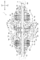
図2は、後輪駆動装置1の全体の縦断面図を示すものであり、図3は、図2の上部部分の拡大断面図である。同図において、符号11は、後輪駆動装置1のケースであり、ケース11は、車幅方向略中央部に配置される中央ケース11Mと、中央ケース11Mを挟むように中央ケース11Mの左右に配置される側方ケース11A、11Bと、から構成され、全体が略円筒状に形成される。ケース11の内部には、後輪Wr用の車軸10A、10Bと、車軸駆動用の第1及び第2電動機2A、2Bと、この第1及び第2電動機2A、2Bの駆動回転を減速する第1及び第2変速機構としての第1及び第2遊星歯車式減速機12A、12Bとが、それらの回転軸線Oが同一直線上に位置するように配置されている。この車軸10A、第1電動機2A及び第1遊星歯車式減速機12Aは左後輪LWrを駆動制御し、車軸10B、第2電動機2B及び第2遊星歯車式減速機12Bは右後輪RWrを駆動制御する。車軸10A、第1電動機2A及び第1遊星歯車式減速機12Aと、車軸10B、第2電動機2B及び第2遊星歯車式減速機12Bは、ケース11内で車幅方向(左右方向)の中間面Mに左右対称に配置されている。<First Embodiment>
First, the vehicle drive device of 1st Embodiment carrying the power transmission device which concerns on this invention is demonstrated based on FIGS. The arrows in the figure indicate the positional relationship when the rear wheel drive device 1 is mounted on the vehicle.
FIG. 2 is a longitudinal sectional view of the entire rear wheel drive device 1, and FIG. 3 is an enlarged sectional view of the upper portion of FIG. In the figure,
側方ケース11A、11Bの中央ケース11M側には、それぞれ径方向内側に延びる隔壁18A、18Bが設けられ、側方ケース11A、11Bと隔壁18A、18Bとに囲まれた空間には、それぞれ第1及び第2電動機2A、2Bが配置される。また、中央ケース11Mと隔壁18A、18Bとに囲まれた空間には、第1及び第2遊星歯車式減速機12A、12Bが隣接して配置されている。言い換えると、隔壁18A、18Bによって、第1及び第2電動機2A、2Bを収容する空間と第1及び第2遊星歯車式減速機12A、12Bを収容する空間が区画されている。
The
第1及び第2電動機2A、2Bは、ステータ14A、14Bがそれぞれ側方ケース11A、11Bに固定され、このステータ14A、14Bの内周側に環状のロータ15A、15Bが回転可能に配置されている。ロータ15A、15Bの内周部には車軸10A、10Bの外周を囲繞する第1及び第2電動機2A、2Bの出力軸としての円筒軸16A、16Bが結合され、この円筒軸16A、16Bが、それぞれ車軸10A、10Bと同軸上に相対回転可能となるように側方ケース11A、11Bの端部壁17A、17Bに軸受Br3、Br4を介して支持されるとともに、隔壁18A、18Bに軸受Br7、Br8を介して支持されている。また、円筒軸16A、16Bの軸方向内側には、後述する第1及び第2遊星歯車式減速機12A、12Bのサンギヤ21A、21Bが一体に形成され、サンギヤ21A、21Bよりもさらに軸方向内側に延出部13A、13Bが形成される。
In the first and second
また、第1及び第2遊星歯車式減速機12A、12Bは、サンギヤ21A、21Bと、このサンギヤ21A、21Bに噛合する複数のプラネタリギヤ22A、22Bと、これらのプラネタリギヤ22A、22Bを支持するプラネタリキャリア23A、23Bと、プラネタリギヤ22A、22Bの外周側に噛合するリングギヤ24A、24Bと、を備え、サンギヤ21A、21Bから第1及び第2電動機2A、2Bの駆動力が入力され、プラネタリキャリア23A、23Bを通して車軸10A、10Bに出力されるようになっている。
The first and second planetary
プラネタリギヤ22A、22Bは、サンギヤ21A、21Bに直接噛合する大径の第1ピニオン26A、26Bと、この第1ピニオン26A、26Bよりも小径の第2ピニオン27A、27Bとを有する2連ピニオンであり、これらの第1ピニオン26A、26Bと第2ピニオン27A、27Bとが同軸にかつ軸方向にオフセットした状態で一体に形成されている。このプラネタリギヤ22A、22Bは、軸受Br9、Br10を介してプラネタリキャリア23A、23Bのピニオンシャフト230に支持される。
The
また、プラネタリキャリア23A、23Bにおいては、軸方向に延設されたピニオンシャフト230の内側端部が、内側腕部231に保持される。内側腕部231は、径方向に延設されたキャリアプレート231aと、キャリアプレート231aの内径側に一体に取り付けられて車軸10A、10Bと一体回転可能にスプライン嵌合するキャリアベース231bとから構成される。キャリアベース231bは、円筒軸16A、16Bの延出部13A、13Bと軸方向でオーバーラップするように延出部13A、13B側に延びており、延出部13A、13Bに軸受Br11、Br12を介して支持される。さらに、キャリアベース231bは、後述するリングギヤ24A、24Bの小径部29A、29Bと軸方向でオーバーラップするように延出部13A、13Bとは反対側にも延びている。
In the planetary carriers 23 </ b> A and 23 </ b> B, the inner end portion of the
一方、ピニオンシャフト230の外側端部は、外側腕部232により軸受Br1、Br2を介して隔壁18A、18Bに支持されている。即ち、隔壁18A、18Bには、それぞれプラネタリキャリア23A、23Bを支持する軸受Br1、Br2と、円筒軸16A、16Bを支持する軸受Br7、Br8とが配置されている。
On the other hand, the outer end of the
また、プラネタリギヤ22A、22Bの軸方向内側端部は、プラネタリキャリア23A、23Bの内側腕部231に支持されており、プラネタリギヤ22A、22Bの軸方向外側端部は、プラネタリキャリア23A、23Bの外側腕部232に支持されている。そのため、プラネタリギヤ22A、22Bとプラネタリキャリア23A、23Bとの間でスラスト力が伝達される。
The axially inner ends of the
リングギヤ24A、24Bは、その内周面が小径の第2ピニオン27A、27Bに噛合するギヤ部28A、28Bと、ギヤ部28A、28Bから径方向内側に延びる内径側延設部41A、41Bとを備えて構成され、内径側延設部41A、41Bは、ケース11の中間位置で互いに対向配置される小径部29A、29Bと、ギヤ部28A、28Bの軸方向内側端部と小径部29A、29Bの軸方向外側端部を径方向に連結する連結部30A、30Bとを備えて構成されている。連結部30A、30Bは、それぞれプラネタリキャリア23A、23Bのキャリアプレート231aに径方向でオーバラップするように対向して配置されており、キャリアプレート231aの内径側には、キャリアプレート231aとの間に軸受Br5、Br6が設けられている。
The ring gears 24A, 24B include
ギヤ部28A、28Bは、中央ケース11Mの左右分割壁45の内径側端部に形成された円筒壁46を挟んで軸方向に対向している。内径側延設部41A、41Bを構成する小径部29A、29Bは、その外周面がそれぞれ後述する一方向クラッチ50のインナーレース51とスプライン嵌合し、リングギヤ24A、24Bは一方向クラッチ50のインナーレース51と一体回転するように構成されている。また、小径部29A、29Bは、軸方向には、対向する端部同士は固定されずに当接可能に配置されている。即ち、リングギヤ24A、24Bは、回転方向に動力伝達可能に連結され、且つ、軸方向で互いに押し合う方向の動力伝達が可能で、軸方向で互いに引き合う方向の動力伝達が不能に連結される。
The
ケース11を構成する中央ケース11Mには、リングギヤ24Bに対する制動手段を構成する油圧ブレーキ60と、一方向クラッチ50とが設けられている。油圧ブレーキ60は、中央ケース11Mの円筒壁44の内周面にスプライン嵌合された複数の固定プレート35と、リングギヤ24Bのギヤ部28Bの外周面にスプライン嵌合された複数の回転プレート36が軸方向に交互に配置され、これらのプレート35、36が環状のピストン37によって締結及び解放操作されるようになっている。従って、両プレート35、36がピストン37によって押し付けられると、両プレート35、36間の摩擦締結によってリングギヤ24Bに制動力が作用し固定される。その状態からピストン37による締結が解放されると、リングギヤ24Bの自由な回転が許容される。なお、上述したように、リングギヤ24A、24Bは互いに連結されているため、油圧ブレーキ60が締結することによりリングギヤ24Aにも制動力が作用し固定され、油圧ブレーキ60が解放することによりリングギヤ24Aも自由な回転が許容される。
A
一方向クラッチ50は、インナーレース51とアウターレース52との間に多数のスプラグ53を介在させたものであって、そのインナーレース51がスプライン嵌合によりリングギヤ24A、24Bの小径部29A、29Bと一体回転するように構成されている。またアウターレース52は、中央ケース11Mの円筒壁46により位置決めされるとともに、回り止めされている。
The one-way clutch 50 has a large number of
一方向クラッチ50は、車両3が第1及び第2電動機2A、2Bの動力で前進する際に係合してリングギヤ24A、24Bの回転をロックするように構成されている。より具体的に説明すると、一方向クラッチ50は、第1及び第2電動機2A、2B側の順方向(車両3を前進させる際の回転方向)の回転動力が後輪Wr側に入力されるときに係合状態となるとともに第1及び第2電動機2A、2B側の逆方向の回転動力が後輪Wr側に入力されるときに非係合状態となり、後輪Wr側の順方向の回転動力が第1及び第2電動機2A、2B側に入力されるときに非係合状態となるとともに後輪Wr側の逆方向の回転動力が第1及び第2電動機2A、2B側に入力されるときに係合状態となる。
The one-way clutch 50 is configured to engage and lock the rotation of the ring gears 24A and 24B when the
このように本実施形態の後輪駆動装置1では、第1及び第2電動機2A、2Bと後輪Wrとの動力伝達経路上に一方向クラッチ50と油圧ブレーキ60とが並列に設けられている。なお、油圧ブレーキ60は、車両の走行状態や一方向クラッチ50の係合・非係合状態に応じて、不図示の電動オイルポンプから供給されるオイルの圧力により、解放状態、弱締結状態、締結状態に制御される。例えば、車両3が第1及び第2電動機2A、2Bの力行駆動により前進する時(低車速時、中車速時)は、油圧ブレーキ60の状態に関わらず一方向クラッチ50が締結するため動力伝達可能な状態となり、車両3が内燃機関4及び/又は第1及び第2電動機5の力行駆動により前進する時(高車速時)は、一方向クラッチ50が非係合となりさらに油圧ブレーキが解放状態に制御されることで、第1及び第2電動機2A、2Bの過回転が防止される。一方、車両3の後進時や回生時には、一方向クラッチ50が非係合となるため油圧ブレーキ60が締結状態に制御されることで、第1及び第2電動機2A、2B側からの逆方向の回転動力が後輪Wr側に出力され、又は後輪Wr側の順方向の回転動力が第1及び第2電動機2A、2B側に入力される。
As described above, in the rear wheel drive device 1 of the present embodiment, the one-way clutch 50 and the
また、本実施形態の後輪駆動装置1において、軸受Br1、Br2は、それぞれプラネタリギヤ22A、22Bに作用する軸方向外側へのスラスト力を受けることができるアンギュラ玉軸受が使用されており、軸受Br3、Br4は、それぞれサンギヤ21A、21Bに作用する軸方向外側へのスラスト力を受けることができるアンギュラ玉軸受が使用されており、軸受Br5、Br6は、それぞれプラネタリギヤ22A、22Bに作用する軸方向内側及び外側へのスラスト力を受けることができるようにスラスト軸受が使用されており、軸受Br7、Br8は、サンギヤ21A、21Bに作用する軸方向内側へのスラスト力を受けることができるアンギュラ玉軸受が使用されている。これに対し、軸受Br9〜12は、スラスト力を受けることのできないニードル軸受が使用されている。なお、軸受Br1〜Br4及び軸受Br7、Br8は、スラスト力を受けることができる軸受であればアンギュラ玉軸受の代わりに円すいころ軸受等の軸受を適宜選択して用いてもよく、また、軸方向内側及び軸方向外側の両方向のスラスト力を受けることができる深溝玉軸受等の軸受を適宜選択して用いてもよい。
Further, in the rear wheel drive device 1 of the present embodiment, the bearings Br1 and Br2 are angular ball bearings that can receive axially outward thrust force acting on the
ここで、プラネタリギヤ22A、22Bの噛み合いについて説明する。
プラネタリギヤ22A、22Bは、図5に示すように、それぞれサンギヤ21A、21Bに噛合される大径の第1ピニオン26A、26Bと、小径の第2ピニオン27A、27Bとの噛合歯の捩れ方向が同一方向になっており、これにより捩れに起因して大径の第1ピニオン26A、26B及び小径の第2ピニオン27A、27Bに発生するスラスト力が互いに反対向きとなる。Here, the meshing of the
As shown in FIG. 5, the
また、サンギヤ21A、21Bに噛合される大径の第1ピニオン26A、26Bのねじれ角θ1が、リングギヤ24A、24Bのギヤ部28A、28Bと噛合される小径の第2ピニオン27A、27Bのねじれ角θ2より大きくなるように設定されており、それにより、プラネタリギヤ22A、22Bで発生するスラスト力が大径の第1ピニオン26A、26Bよりも小径の第2ピニオン27A、27Bで大きくなっている。
In addition, the torsion angle θ1 of the large-diameter
なお、第1遊星歯車式減速機12Aのプラネタリギヤ22Aと、第2遊星歯車式減速機12Bのプラネタリギヤ22Bとは、第1及び第2遊星歯車式減速機12A、12Bの回転軸線Oを含む直線と鉛直であり、且つ、第1及び第2遊星歯車式減速機12A、12B間に位置する中間面Mに対して鏡対称の関係にあり、噛合歯のねじれ角θ1、θ2についても同様に鏡対称の関係にある。そのため、プラネタリギヤ22Aとプラネタリギヤ22Bとでは、第1及び第2電動機2A、2Bからの入力トルクが等しい場合には、小径の第2ピニオン27A、27Bの噛合部で発生するスラスト力と、大径の第1ピニオン26A、26Bの噛合部で発生するスラスト力との合計である、プラネタリギヤ22A、22Bに作用するスラスト力(以下、プラネタリギヤ合計スラスト力とも呼ぶ。)が、中間面Mに対して鏡対称の関係となる。
The
図6は、直進加速時、即ち第1及び第2電動機2A、2Bが順方向に略同等の力行トルクを発生した場合の、後輪駆動装置1に発生するスラスト力を示すブロック図である。図6〜図10において、回転軸線O周りの矢印は第1及び第2電動機2A、2Bのトルクを示すものであり、時計回りの矢印が順方向のトルク(例えば、車両前進時の力行トルク)を示し、反時計回りの矢印が逆方向のトルク(例えば、車両前進時の回生トルク)を示している。それぞれのギヤにオーバーラップして描かれたハッチング付の矢印は、それぞれのギヤで発生するスラスト力であり、白抜きの矢印はプラネタリギヤ合計スラスト力を示すものであり、黒塗りの矢印は、第1遊星歯車式減速機12Aのリングギヤ24Aの噛合部で発生するスラスト力と、第2遊星歯車式減速機12Bのリングギヤ24Bの噛合部で発生するスラスト力との合計で、リングギヤ24A、24Bに作用するスラスト力(以下、リングギヤ合計スラスト力とも呼ぶ。)を示すものである。また、スラスト力を受ける軸受にはドットを付すことで、スラスト力を受けない軸受と区別している。
FIG. 6 is a block diagram showing the thrust force generated in the rear wheel drive device 1 during linear acceleration, that is, when the first and
図6に示すように、直進加速時に第1及び第2電動機2A、2Bから順方向の力行トルクが入力されると、サンギヤ21A、21Bには、大径の第1ピニオン26A、26Bとの噛合により、軸方向外側へのスラスト力(離れる向きの力)が作用し、大径の第1ピニオン26A、26Bには、軸方向内側へのスラスト力(近づく向きの力)が作用する。また、小径の第2ピニオン27A、27Bには、リングギヤ24A、24Bとの噛合により、軸方向外側へのスラスト力が作用し、リングギヤ24A、24Bには、軸方向内側へのスラスト力が作用する。上述したように、捩れ角の違いからスラスト力は、大径の第1ピニオン26A、26Bよりも小径の第2ピニオン27A、27Bで大きくなっており、これにより、それぞれのプラネタリギヤ22A、22Bでは、軸方向外側へのプラネタリギヤ合計スラスト力が作用することとなる。
As shown in FIG. 6, when forward powering torque is input from the first and
このプラネタリギヤ22A、22Bに作用する軸方向外側へのプラネタリギヤ合計スラスト力は、プラネタリキャリア23A、23Bを介してそれぞれ軸受Br1、Br2で受けられる。また、サンギヤ21A、21Bに作用する軸方向外側へのスラスト力は、それぞれ軸受Br3、Br4で受けられる。そして、リングギヤ24A、24Bに作用する軸方向内側へのスラスト力は、小径部29A、29Bで互いに押し合うことで相殺される。即ち、この直進加速時には、リングギヤ24A、24Bに作用する軸方向内側へのスラスト力は、第1及び第2電動機2A、2Bの力行トルクが等しいことから等しくなり、リングギヤ24A、24Bの小径部29A、29Bでスラスト力が打ち消される。これにより、第1遊星歯車式減速機12Aと第2遊星歯車式減速機12Bとで、閉じた系をなし、閉じた系の中でスラスト力が支持される。
The axially outward planetary gear total thrust force acting on the
図7は、直進減速時、即ち第1及び第2電動機2A、2Bが逆方向に略同等の回生トルクを発生した場合の、後輪駆動装置1に発生するスラスト力を示すブロック図である。
図7に示すように、直進減速時に第1及び第2電動機2A、2Bから逆方向の回生トルクが入力されると、サンギヤ21A、21Bには、大径の第1ピニオン26A、26Bとの噛合により、軸方向内側へのスラスト力が作用し、大径の第1ピニオン26A、26Bには、軸方向外側へのスラスト力が作用する。また、小径の第2ピニオン27A、27Bには、リングギヤ24A、24Bとの噛合により、軸方向内側へのスラスト力が作用し、リングギヤ24A、24Bには、軸方向外側へのスラスト力が作用する。上述したように、捩れ角の違いからスラスト力は、大径の第1ピニオン26A、26Bよりも小径の第2ピニオン27A、27Bで大きくなっており、これにより、それぞれのプラネタリギヤ22A、22Bでは、軸方向内側へのプラネタリギヤ合計スラスト力が作用することとなる。FIG. 7 is a block diagram showing the thrust force generated in the rear wheel drive device 1 during linear deceleration, that is, when the first and
As shown in FIG. 7, when reverse regenerative torque is input from the first and second
このプラネタリギヤ22A、22Bに作用する軸方向内側へのプラネタリギヤ合計スラスト力は、プラネタリキャリア23A、23Bを介してそれぞれ軸受Br5、Br6で受けられ、さらにリングギヤ24A、24Bに伝達される。そして、リングギヤ24A、24Bに作用する軸方向外側へのスラスト力から、この軸受Br5、Br6を介してリングギヤ24A、24Bに伝達された軸方向内側へのスラスト力を差し引いたスラスト力が、リングギヤ24A、24Bの小径部29A、29Bを互いに離間するように移動させる。また、サンギヤ21A、21Bに作用する軸方向内側へのスラスト力は、それぞれ軸受Br7、Br8で受けられる。即ち、この直進減速時には、リングギヤ24A、24Bに作用する軸方向外側へのスラスト力が、リングギヤ24A、24Bの小径部29A、29Bを離間させる。これにより、第1遊星歯車式減速機12Aと第2遊星歯車式減速機12Bとで、それぞれ独立して閉じた系をなし、閉じた系の中でスラスト力が支持される。
The axially total planetary gear thrust force acting on the
なお、図7のスラスト力の関係は、直進減速時のみならず、後進加速時にも同様の関係となる。この場合は、第1及び第2電動機2A、2Bにより逆方向の力行トルクが入力される。
Note that the relationship of the thrust force in FIG. 7 is the same relationship not only at the time of linear deceleration but also at the time of reverse acceleration. In this case, power running torque in the reverse direction is input by the first and second
図8は、旋回加速時であって、第1電動機2Aの順方向の力行トルクが、第2電動機2Bの順方向の力行トルクより大きい場合(右旋回)の、後輪駆動装置1に発生するスラスト力を示すブロック図である。
図8に示すように、このときの各ギヤに作用するスラスト力の方向は、図6の直進加速時と同様であるが、第1電動機2Aの順方向の力行トルクが、第2電動機2Bの順方向の力行トルクより大きいため、第1遊星歯車式減速機12Aに作用するプラネタリギヤ合計スラスト力が、第2遊星歯車式減速機12Bに作用するプラネタリギヤ合計スラスト力より大きくなっている。また、リングギヤ24Aに作用するスラスト力も、リングギヤ24Bに作用するスラスト力より大きく、その差分が相殺されずにリングギヤ合計スラスト力として、第1遊星歯車式減速機12Aの小径部29Aから第2遊星歯車式減速機12Bの小径部29Bに向かって作用している。このリングギヤ合計スラスト力は、軸受Br6で受けられ、さらにプラネタリキャリア23Bに伝達される。そしてこのリングギヤ合計スラスト力に、プラネタリギヤ22Bに作用する軸方向外側へのプラネタリギヤ合計スラスト力を加えたスラスト力が軸受Br2で受けられる。即ち、この旋回加速時には、リングギヤ24A、24Bの小径部29A、29Bでスラスト力の一部が相殺されずに、スラスト力の差分が第1遊星歯車式減速機12Aと第2遊星歯車式減速機12Bとの間で移動することとなる。FIG. 8 is generated in the rear-wheel drive device 1 during acceleration of turning, and when the forward powering torque of the first
As shown in FIG. 8, the direction of the thrust force acting on each gear at this time is the same as that in the straight acceleration of FIG. 6, but the forward power running torque of the
なお、図示は省略するが、第2電動機2Bの順方向の力行トルクが、第1電動機2Aの順方向の力行トルクより大きい場合(左旋回)は、リングギヤ24Bに作用する軸方向内側へのスラスト力が、リングギヤ24Aに作用する軸方向内側へのスラスト力より大きく、その差分が相殺されずリングギヤ合計スラスト力として、小径部29Bから小径部29Aに向かって作用する。このリングギヤ合計スラスト力は、軸受Br5で受けられ、さらにリングギヤ合計スラスト力にプラネタリギヤ合計スラスト力を加えたスラスト力が軸受Br1で受けられることとなる。
Although illustration is omitted, when the forward power running torque of the second
図9は、旋回減速時であって、第1電動機2Aの逆方向の回生トルクが、第2電動機2Bの逆方向の回生トルクより大きい場合(左旋回)の、後輪駆動装置1に発生するスラスト力を示すブロック図である。
図9に示すように、このときの各ギヤに作用するスラスト力の方向は、図7の直進減速時と同様であるが、第1電動機2Aの逆方向の回生トルクが、第2電動機2Bの逆方向の回生トルクより大きいため、第1遊星歯車式減速機12Aに作用するプラネタリギヤ合計スラスト力が、第2遊星歯車式減速機12Bに作用するプラネタリギヤ合計スラスト力より大きくなっている。また、リングギヤ24Aに作用するスラスト力も、リングギヤ24Bに作用するスラスト力より大きく、小径部29Aの移動量が小径部29Bの移動量より大きくなる。ただし、この旋回減速時には、小径部29A、29Bは互いに離間するため、リングギヤ合計スラスト力が、第1遊星歯車式減速機12Aと第2遊星歯車式減速機12Bとの間で作用することはなく、第1遊星歯車式減速機12Aと第2遊星歯車式減速機12Bとで、それぞれ独立して閉じた系をなし、閉じた系の中でスラスト力が支持される。FIG. 9 is generated at the rear wheel drive device 1 when the vehicle is decelerating and the regenerative torque in the reverse direction of the first
As shown in FIG. 9, the direction of the thrust force acting on each gear at this time is the same as in the case of the linear deceleration of FIG. 7, but the regenerative torque in the reverse direction of the
なお、図示は省略するが、第2電動機2Bの逆方向の回生トルクが、第1電動機2Aの逆方向の回生トルクより大きい場合(右旋回)は、第2遊星歯車式減速機12Bに作用するプラネタリギヤ合計スラスト力が、第1遊星歯車式減速機12Aに作用するプラネタリギヤ合計スラスト力より大きくなるが、図9の場合と同様に、小径部29A、29Bは互いに離間するため、リングギヤ合計スラスト力が、第1遊星歯車式減速機12Aと第2遊星歯車式減速機12Bとの間で作用することはない。
Although illustration is omitted, when the regenerative torque in the reverse direction of the second
図10は、旋回時であって、第1電動機2Aが順方向の力行トルクを発生し、第2電動機2Bが逆方向の回生トルクを発生した場合(右旋回)の、後輪駆動装置1に発生するスラスト力を示すブロックである。
FIG. 10 shows the rear-wheel drive device 1 when turning, in which the
図10に示すように、第1電動機2Aから順方向の力行トルクを作用させると、サンギヤ21Aには、大径の第1ピニオン26Aとの噛合により、軸方向外側へのスラスト力が作用し、大径の第1ピニオン26Aには、軸方向内側へのスラスト力が作用する。また、小径の第2ピニオン27Aには、リングギヤ24Aとの噛合により、軸方向外側へのスラスト力が作用し、リングギヤ24Aには、軸方向内側へのスラスト力が作用する。上述したように、捩れ角の違いからスラスト力は、大径の第1ピニオン26Aよりも小径の第2ピニオン27Aで大きくなっており、これにより、プラネタリギヤ22Aでは、軸方向外側へのプラネタリギヤ合計スラスト力が作用することとなる。
As shown in FIG. 10, when a forward power running torque is applied from the first
一方、第2電動機2Bから逆方向の回生トルクを作用させると、サンギヤ21Bには、大径の第1ピニオン26Bとの噛合により、軸方向内側へのスラスト力が作用し、大径の第1ピニオン26Bには、軸方向外側へのスラスト力が作用する。また、小径の第2ピニオン27Bには、リングギヤ24Bとの噛合により、軸方向内側へのスラスト力が作用し、リングギヤ24Bには、軸方向外側へのスラスト力が作用する。上述したように、捩れ角の違いからスラスト力は、大径の第1ピニオン26Bよりも小径の第2ピニオン27Bで大きくなっており、これにより、プラネタリギヤ22Bでは、軸方向内側へのプラネタリギヤ合計スラスト力が作用することとなる。
On the other hand, when a regenerative torque in the reverse direction is applied from the second
このとき、リングギヤ24A、24Bは同じ方向、即ち第1遊星歯車式減速機12A側から第2遊星歯車式減速機12B側に向かって移動するが、リングギヤ24Bは軸受Br6によって移動が規制されるため、小径部29Aが小径部29Bに当接し、リングギヤ24Aに作用する軸方向内側へのスラスト力とリングギヤ24Bに作用する軸方向外側へのスラスト力の合力であるスラスト力リングギヤ合計スラスト力が作用することとなる。
At this time, the ring gears 24A and 24B move in the same direction, that is, from the first planetary gear
このリングギヤ合計スラスト力は、軸受Br6で受けられ、さらにプラネタリキャリア23Bに伝達される。そしてこのリングギヤ合計スラスト力から、プラネタリギヤ22Bに作用する軸方向内側へのプラネタリギヤ合計スラスト力を差し引いたスラスト力が、軸受Br2で受けられる。また、プラネタリギヤ22Aに作用する軸方向外側へのプラネタリギヤ合計スラスト力は、プラネタリキャリア23Aを介して軸受Br1で受けられる。また、サンギヤ21Aに作用する軸方向外側へのスラスト力は、軸受Br3で受けられる。さらに、サンギヤ21Bに作用する軸方向内側へのスラスト力は、軸受Br8で受けられる。即ち、この旋回時には、リングギヤ24A、24Bの小径部29A、29Bでスラスト力が足し合わされて、足し合わされたスラスト力が第1遊星歯車式減速機12Aと第2遊星歯車式減速機12Bとの間で移動することとなる。
This ring gear total thrust force is received by the bearing Br6 and further transmitted to the
このように構成された本実施形態の後輪駆動装置1では、第1及び第2電動機2A、2Bが順方向にトルクを発生するとき、リングギヤ24A、24Bには、互いに近づく向きの力である軸方向内側へのスラスト力が作用するので、リングギヤ24A、24Bに作用するスラスト力を相殺することができる。特に、第1及び第2電動機2A、2Bが順方向に等しいトルクを発生するとき、リングギヤ24A、24Bに作用するスラスト力を完全に打ち消しあうことができる。そして、車両の走行頻度が一番多い前進加速時に、リングギヤ24A、24Bに作用するスラスト力を打ち消しあうように設定することで、軸受の負荷を軽減させることができる。
In the rear wheel drive device 1 of this embodiment configured as described above, when the first and second
また、このとき、サンギヤ21A、21Bには、それぞれ軸方向外側へのスラスト力が作用し、これを軸受Br3、Br4で受けるようにしたことで、過度にサンギヤ21A、21Bが移動することを防止することができる。さらに、このとき、プラネタリギヤ22A、22Bには、それぞれ軸方向外側へのプラネタリギヤ合計スラスト力が作用し、これを軸受Br1、Br2で受けるようにしたことで、過度にプラネタリギヤ22A、22Bが移動することを防止することができる。なお、プラネタリギヤ22A、22Bを2段ピニオンとすることで、歯面の傾斜などの噛合状態を別個独立に形成することができ、プラネタリギヤ合計スラスト力の方向と大きさを調整することができる。
Further, at this time, the axially outward thrust force acts on the sun gears 21A and 21B, respectively, and this is received by the bearings Br3 and Br4, thereby preventing the sun gears 21A and 21B from moving excessively. can do. Further, at this time, the
一方、第1及び第2電動機2A、2Bが逆方向にトルクを発生するとき、リングギヤ24A、24Bには、互いに離れる向きの力である軸方向外側へのスラスト力が作用するので、第1遊星歯車式減速機12Aと第2遊星歯車式減速機12Bとで系を分けることができる。系を分けることで、一方側に過度にスラスト力が作用するのを抑制することができる。
On the other hand, when the first and second
また、このとき、サンギヤ21A、21Bには、それぞれ軸方向内側へのスラスト力が作用し、これを軸受Br7、Br8で受けるようにしたことで、過度にサンギヤ21A、21Bが移動することを防止することができる。さらに、このとき、プラネタリギヤ22A、22Bには、それぞれ軸方向内側へのプラネタリギヤ合計スラスト力が作用し、これを軸受Br5、Br6で受けるようにしたことで、過度にプラネタリギヤ22A、22Bが移動するのを抑制することができる。
Further, at this time, the axially inner thrust force acts on the sun gears 21A and 21B, and these are received by the bearings Br7 and Br8, thereby preventing the sun gears 21A and 21B from moving excessively. can do. Further, at this time, the
なお、旋回時には、軸受Br1、Br2に比較的大きなスラスト力が作用する場合もあるが、旋回加速時等は、車両の走行モードにおいて頻度が低いため、軸受Br1、Br2の負荷は少なくてすむ。逆に言うと、軸受Br1、Br2のみ比較的大きなスラスト力を受けることができるようにしておくことで、信頼性を確保することができる。 During turning, a relatively large thrust force may act on the bearings Br1 and Br2. However, during turning acceleration and the like, since the frequency is low in the traveling mode of the vehicle, the load on the bearings Br1 and Br2 can be reduced. In other words, reliability can be ensured by allowing only the bearings Br1 and Br2 to receive a relatively large thrust force.
<第2実施形態>
続いて、本発明に係る動力伝達装置を搭載した第2実施形態の車両用駆動装置について、図11に基づいて説明する。なお、第1実施形態と同一又は同等の構成については、同一又は同等の符号を付してその説明を省略する。Second Embodiment
Then, the vehicle drive device of 2nd Embodiment carrying the power transmission device which concerns on this invention is demonstrated based on FIG. In addition, about the structure same or equivalent to 1st Embodiment, the code | symbol same or equivalent is attached | subjected and the description is abbreviate | omitted.
本実施形態の後輪駆動装置1Aでは、リングギヤ24A、24Bが、小径部29A、29B及び連結部30A、30B(を有さず、第1遊星歯車式減速機12Aのギヤ部28Aの第2遊星歯車式減速機12B側の端部から延設される軸方向延設部40Aと、第2遊星歯車式減速機12Bのギヤ部28Bの第1遊星歯車式減速機12A側の端部から延設される軸方向延設部40Bとが、当接するように一体に構成されている点で第1実施形態の後輪駆動装置1と異なっている。
In the rear
即ち、本実施形態の後輪駆動装置1Aでは、リングギヤ24A、24Bは、回転方向に動力伝達可能に連結され、且つ、軸方向で互いに押し合う方向及び軸方向で互いに引き合う方向の動力伝達が可能に連結される。従って、リングギヤ24A、24Bは、軸方向で互いに押し合う又は引き合う方向のスラスト力であって、リングギヤ24Aに作用するスラスト力とリングギヤ24Bに作用するスラスト力とに差がある場合には、連結された状態で移動可能となっている。
That is, in the rear
また、プラネタリキャリア23Aの内側腕部231と、プラネタリキャリア23Bの内側腕部231との間には、スラスト軸受である軸受Br13が設けられており、軸受Br13が、プラネタリキャリア23A、23B間のスラスト力を受けるように構成される。即ち、第1実施形態における軸受Br5、Br6の役割を軸受Br13が担っている。
A bearing Br13, which is a thrust bearing, is provided between the
このように構成された本実施形態の後輪駆動装置1Aでも、第1実施形態と同様に、第1及び第2電動機2A、2Bが順方向にトルクを発生するとき、リングギヤ24A、24Bには、互いに近づく向きの力である軸方向内側へのスラスト力が作用するので、リングギヤ24A、24Bに作用するスラスト力を相殺することができる。
Also in the rear
また、このとき、サンギヤ21A、21Bには、それぞれ軸方向外側へのスラスト力が作用し、これを軸受Br3、Br4で受けるようにしたことで、過度にサンギヤ21A、21Bが移動することを防止することができる。さらに、このとき、プラネタリギヤ22A、22Bには、それぞれ軸方向外側へのプラネタリギヤ合計スラスト力が作用し、これを軸受Br1、Br2で受けるようにしたことで、過度にプラネタリギヤ22A、22Bが移動することを防止することができる。
Further, at this time, the axially outward thrust force acts on the sun gears 21A and 21B, respectively, and this is received by the bearings Br3 and Br4, thereby preventing the sun gears 21A and 21B from moving excessively. can do. Further, at this time, the
一方、第1及び第2電動機2A、2Bが逆方向に等しいトルクを発生するとき、リングギヤ24A、24Bには、互いに離れる向きの力である軸方向外側へのスラスト力が作用するものの、リングギヤ24A、24Bが軸方向にも連結されているので、スラスト力を相殺することができる。
On the other hand, when the first and second
また、このとき、サンギヤ21A、21Bには、それぞれ軸方向内側へのスラスト力が作用し、これを軸受Br7、Br8で受けるようにしたことで、過度にサンギヤ21A、21Bが移動することを防止することができる。さらに、このとき、プラネタリギヤ22A、22Bには、それぞれ軸方向内側へのプラネタリギヤ合計スラスト力が作用し、これを軸受Br13で受けるようにしたことで、過度にプラネタリギヤ22A、22Bが移動するのを抑制することができる。
Further, at this time, the axially inner thrust force acts on the sun gears 21A and 21B, and these are received by the bearings Br7 and Br8, thereby preventing the sun gears 21A and 21B from moving excessively. can do. Further, at this time, the
ただし、第1及び第2電動機2A、2Bで発生するトルクの大きさが異なる場合、例えば図8〜図10に示した旋回加速時、旋回減速時、旋回時には、第1実施形態と異なり、リングギヤ24A、24Bが軸方向にも連結されて移動可能になっているので、リングギヤ24A、24Bに作用するスラスト力の差分がリングギヤ合計スラスト力として、リングギヤ24A、24Bを移動させることで、プラネタリキャリア23A、23Bなどの他部材に伝えずにスラスト力を解放させることができる。
However, when the magnitudes of torque generated in the first and second
これらの場合であっても、サンギヤ21A、21Bに作用する軸方向外側へのスラスト力はそれぞれ軸受Br3、Br4で受けられ、サンギヤ21A、21Bに作用する軸方向内側へのスラスト力はそれぞれ軸受Br7、Br8で受けられ、プラネタリギヤ22A、22Bに作用する軸方向外側へのスラスト力はそれぞれ軸受Br1、Br2で受けられ、プラネタリギヤ22A、22Bに作用する軸方向内側へのスラスト力は軸受Br13で受けられ、さらにプラネタリキャリア23A、23Bを介してそれぞれ軸受Br1、Br2で受けられる。
Even in these cases, the axially outward thrust force acting on the sun gears 21A and 21B is received by the bearings Br3 and Br4, respectively, and the axially inward thrust force acting on the sun gears 21A and 21B is respectively the bearings Br7. , Br8 and axially outward thrust force acting on the
なお、本実施形態では、軸方向延設部40Aと軸方向延設部40Bとは必ずしも一体に構成されていなくてもよく、軸方向に連結されていればよい。
In the present embodiment, the
<第3実施形態>
続いて、本発明に係る動力伝達装置を搭載した第3実施形態の車両用駆動装置について、図12に基づいて説明する。なお、第2実施形態と同一又は同等の構成については、同一又は同等の符号を付してその説明を省略する。<Third Embodiment>
Then, the vehicle drive device of 3rd Embodiment carrying the power transmission device which concerns on this invention is demonstrated based on FIG. In addition, about the structure same or equivalent to 2nd Embodiment, the code | symbol same or equivalent is attached | subjected and the description is abbreviate | omitted.
本実施形態の後輪駆動装置1Bでは、第1遊星歯車式減速機12Aのギヤ部28Aの第2遊星歯車式減速機12B側の端部から延設される軸方向延設部40Aと、第2遊星歯車式減速機12Bのギヤ部28Bの第1遊星歯車式減速機12A側の端部から延設される軸方向延設部40Bとが、別体で当接するように配置されており、さらに、軸方向延設部40Aの軸方向延設部40Bとは反対側に軸方向への移動を規制するストッパー42Aが設けられ、軸方向延設部40Bの軸方向延設部40Aとは反対側に軸方向への移動を規制するストッパー42Bが設けられている点で第2実施形態の後輪駆動装置1Bと異なっている。
In the rear
即ち、本実施形態の後輪駆動装置1Bでは、リングギヤ24A、24Bは、軸方向で互いに押し合う方向の動力伝達が可能で、軸方向で互いに引き合う方向の動力伝達が不能に連結される。そして、リングギヤ24A、24Bは、軸方向で異なる大きさの近づく向きのスラスト力が作用する、又は互いに離れる向きのスラスト力が作用すると、少なくとも一方のストッパー42A、42Bにより、その移動が規制されるようになっている。
In other words, in the rear
また、一方向クラッチ50及び油圧ブレーキ60がいずれも設けられておらず、リングギヤ24A、24Bが、ケース11に固定されて回転不能に連結されている。従って、プラネタリキャリア23A、23Bに連結される車軸10A、10Bが回転している限り、サンギヤ21A、21Bに連結されている第1及び第2電動機2A、2Bも回転することとなるが、第1及び第2電動機2A、2Bとしてインダクションモータを用いることで、逆起電力の発生を防止することができる。
Further, neither the one-way clutch 50 nor the
このように構成された本実施形態の後輪駆動装置1Bでも、第2実施形態と同様に、第1及び第2電動機2A、2Bが順方向にトルクを発生するとき、リングギヤ24A、24Bには、互いに近づく向きの力である軸方向内側へのスラスト力が作用するので、リングギヤ24A、24Bに作用するスラスト力を相殺することができる。
Also in the rear
また、このとき、サンギヤ21A、21Bには、それぞれ軸方向外側へのスラスト力が作用し、これを軸受Br3、Br4で受けるようにしたことで、過度にサンギヤ21A、21Bが移動することを防止することができる。さらに、このとき、プラネタリギヤ22A、22Bには、それぞれ軸方向外側へのプラネタリギヤ合計スラスト力が作用し、これを軸受Br1、Br2で受けるようにしたことで、過度にプラネタリギヤ22A、22Bが移動することを防止することができる。
Further, at this time, the axially outward thrust force acts on the sun gears 21A and 21B, respectively, and this is received by the bearings Br3 and Br4, thereby preventing the sun gears 21A and 21B from moving excessively. can do. Further, at this time, the
一方、第1及び第2電動機2A、2Bの少なくとも一方が逆方向にトルクを発生するとき若しくは順方向にトルクを発生するときであってもトルクの大きさが異なる場合、リングギヤ24A、24Bには、いずれか一方に又は互いに軸方向外側へのスラスト力が作用するものの、それぞれのストッパー42A、42Bで軸方向外側へのスラスト力を受けることで、リングギヤ24A、24Bに働く軸方向外側へのスラスト力をプラネタリキャリア23A、23Bなどの他部材に伝えずにストッパー42A、42Bで吸収することができる。
On the other hand, if at least one of the first and second
この場合であっても、サンギヤ21A、21Bに作用する軸方向外側へのスラスト力はそれぞれ軸受Br3、Br4で受けられ、サンギヤ21A、21Bに作用する軸方向内側へのスラスト力はそれぞれ軸受Br7、Br8で受けられ、プラネタリギヤ22A、22Bに作用する軸方向外側へのスラスト力はそれぞれ軸受Br1、Br2で受けられ、プラネタリギヤ22A、22Bに作用する軸方向内側へのスラスト力は軸受Br13で受けられ、さらにプラネタリキャリア23A、23Bを介してそれぞれ軸受Br1、Br2で受けられる。
Even in this case, the axially outward thrust force acting on the sun gears 21A and 21B is received by the bearings Br3 and Br4, respectively, and the axially inward thrust force acting on the sun gears 21A and 21B is respectively received by the bearings Br7 and Br7. The axially outward thrust force received by Br8 and acting on the
なお、軸方向延設部40Aと軸方向延設部40Bとは必ずしも別体に構成されていなくてもよく、一体に構成されていてもよい。
Note that the
尚、本発明は、上述した実施形態に限定されるものではなく、適宜、変形、改良、等が可能である。
例えば、変速機構として遊星歯車式減速機を例示したがこれに限らず、通常の歯車式変速機等を用いてもよい。
また、第1及び第2実施形態においても、一方向クラッチ50及び/又は油圧ブレーキ60を省略してもよく、反対に、第3実施形態において、一方向クラッチ50及び/又は油圧ブレーキ60を設けてもよい。In addition, this invention is not limited to embodiment mentioned above, A deformation | transformation, improvement, etc. are possible suitably.
For example, the planetary gear type reduction gear is exemplified as the speed change mechanism, but the invention is not limited to this, and a normal gear type transmission or the like may be used.
Also in the first and second embodiments, the one-way clutch 50 and / or the
なお、本出願は、2011年12月1日出願の日本特許出願(特願2011−263942)に基づくものであり、その内容はここに参照として取り込まれる。 This application is based on a Japanese patent application filed on December 1, 2011 (Japanese Patent Application No. 2011-263944), the contents of which are incorporated herein by reference.
2A 第1電動機(第1駆動源)
2B 第2電動機(第2駆動源)
3 車両
11 ケース(固定部)
12A 第1遊星歯車式減速機(第1変速機構)
12B 第2遊星歯車式減速機(第2変速機構)
16A、16B 円筒軸(出力軸)
18A 隔壁(第1区画壁)
18B 隔壁(第2区画壁)
21A、21B サンギヤ(第3回転要素)
22A、22B プラネタリギヤ(第2回転要素)
23A、23B プラネタリキャリア
24A、24B リングギヤ(第1回転要素)
26A、26B 第1ピニオン(大径ピニオン)
27A、27B 第2ピニオン(小径ピニオン)
28A、28B ギヤ部
40A、40B 軸方向延設部(延設部)
41A、41B 内径側延設部(延設部)
42A、42B ストッパー
Br1 軸受(第1軸受)
Br2 軸受(第2軸受)
Br3 軸受(第3軸受)
Br4 軸受(第4軸受)
Br5 軸受(第5軸受)
Br6 軸受(第6軸受)
Br7 軸受(第7軸受)
Br8 軸受(第8軸受)
Br13 軸受(第5軸受、第6軸受)
LWr 左後輪(左車輪)
RWr 右後輪(右車輪)2A 1st electric motor (1st drive source)
2B Second electric motor (second drive source)
3
12A First planetary gear reducer (first transmission mechanism)
12B Second planetary gear type speed reducer (second transmission mechanism)
16A, 16B Cylindrical shaft (output shaft)
18A Bulkhead (1st partition wall)
18B Bulkhead (2nd partition wall)
21A, 21B Sun gear (third rotating element)
22A, 22B Planetary gear (second rotating element)
23A,
26A, 26B 1st pinion (large diameter pinion)
27A, 27B Second pinion (small pinion)
28A,
41A, 41B Inner diameter side extension part (extension part)
42A, 42B Stopper Br1 bearing (first bearing)
Br2 bearing (second bearing)
Br3 bearing (third bearing)
Br4 bearing (fourth bearing)
Br5 bearing (fifth bearing)
Br6 bearing (sixth bearing)
Br7 bearing (seventh bearing)
Br8 bearing (eighth bearing)
Br13 bearing (5th bearing, 6th bearing)
LWr Left rear wheel (left wheel)
RWr Right rear wheel (right wheel)
Claims (20)
前記第1変速機構の第1回転要素と、前記第2変速機構の第1回転要素とは、互いに一体回転可能に連結されて同一の回転軸線を有する動力伝達装置であって、
前記第1変速機構は、前記第1回転要素と噛合する第2回転要素を備え、
該第1回転要素と、該第2回転要素との噛合部は、前記第1駆動源が一方向への回転トルクを発生するときに、前記第1変速機構の前記第1回転要素に、前記回転軸線方向で前記第2変速機構に近づく向きに力が働くように形成され、
前記第2変速機構は、前記第1回転要素と噛合する第2回転要素を備え、
該第1回転要素と、該第2回転要素との噛合部は、前記第2駆動源が一方向への回転トルクを発生するときに、前記第2変速機構の前記第1回転要素に、前記回転軸線方向で前記第1変速機構に近づく向きに力が働くように形成され、
前記第1変速機構と前記第2変速機構とは、それぞれ遊星歯車機構であって、
前記遊星歯車機構は、サンギヤと、該サンギヤに噛合するプラネタリギヤと、該プラネタリギヤを支持するプラネタリキャリアと、前記プラネタリギヤの外周側に噛合するリングギヤと、を備え、
前記第1回転要素は、前記リングギヤであり、
前記第2回転要素は、前記プラネタリギヤであることを特徴とする動力伝達装置。 A first speed change mechanism connected to the output shaft of the first drive source; and a second speed change mechanism connected to the output shaft of the second drive source, wherein the first speed change mechanism and the second speed change mechanism are Each having a plurality of rotating elements,
The first rotating element of the first speed change mechanism and the first rotating element of the second speed change mechanism are coupled to each other so as to be integrally rotatable and have the same rotation axis,
The first speed change mechanism includes a second rotating element that meshes with the first rotating element,
When the first drive source generates rotational torque in one direction, the meshing portion between the first rotational element and the second rotational element is connected to the first rotational element of the first transmission mechanism. Formed so that a force acts in a direction approaching the second speed change mechanism in the rotation axis direction;
The second speed change mechanism includes a second rotation element meshing with the first rotation element,
When the second drive source generates rotational torque in one direction, the meshing portion between the first rotational element and the second rotational element is connected to the first rotational element of the second transmission mechanism. Formed so that a force acts in a direction approaching the first speed change mechanism in the rotation axis direction ;
Each of the first transmission mechanism and the second transmission mechanism is a planetary gear mechanism,
The planetary gear mechanism includes a sun gear, a planetary gear that meshes with the sun gear, a planetary carrier that supports the planetary gear, and a ring gear that meshes with the outer peripheral side of the planetary gear,
The first rotating element is the ring gear;
The power transmission device , wherein the second rotation element is the planetary gear .
前記第2変速機構の前記第1回転要素と前記第2回転要素との噛合部は、前記第2駆動源が前記一方向への回転トルクを発生するときに、前記第2変速機構の前記第2回転要素に、前記回転軸線方向で前記第1変速機構から離れる向きに力が働くように形成され、
前記第1変速機構の前記第2回転要素に対し、前記回転軸線方向で前記第2変速機構とは反対側に、該第2回転要素に加わる前記回転軸線方向の力を受けることのできる第1軸受が配置され、
前記第2変速機構の前記第2回転要素に対し、前記回転軸線方向で前記第1変速機構とは反対側に、該第2回転要素に加わる前記回転軸線方向の力を受けることのできる第2軸受が配置されることを特徴とする請求項1に記載の動力伝達装置。 The meshing portion between the first rotating element and the second rotating element of the first speed change mechanism is configured such that when the first drive source generates rotational torque in the one direction, the first speed change mechanism of the first speed change mechanism. The two-rotation element is formed such that a force acts in a direction away from the second transmission mechanism in the rotation axis direction,
The meshing portion between the first rotating element and the second rotating element of the second speed change mechanism is configured such that when the second drive source generates rotational torque in the one direction, the first speed of the second speed change mechanism is increased. A force is applied to the two rotating elements in a direction away from the first speed change mechanism in the direction of the rotation axis;
A first force capable of receiving a force in the direction of the rotation axis applied to the second rotation element on a side opposite to the second transmission mechanism in the rotation axis direction with respect to the second rotation element of the first transmission mechanism. Bearings are placed,
A second force capable of receiving a force in the direction of the rotation axis applied to the second rotation element on the side opposite to the first speed change mechanism in the rotation axis direction relative to the second rotation element of the second transmission mechanism. The power transmission device according to claim 1, wherein a bearing is disposed.
前記第2変速機構は、前記第2回転要素と噛合する第3回転要素を備え、該第2回転要素と該第3回転要素との噛合部は、前記第2駆動源が前記一方向への回転トルクを発生するときに、前記第2変速機構の前記第3回転要素に、前記回転軸線方向で前記第1変速機構から離れる向きに力が働くように形成され、
前記第1変速機構の前記第3回転要素に対し、前記回転軸線方向で前記第2変速機構とは反対側に、該第3回転要素に加わる前記回転軸線方向の力を受けることのできる第3軸受が配置され、
前記第2変速機構の前記第3回転要素に対し、前記回転軸線方向で前記第1変速機構とは反対側に、該第3回転要素に加わる前記回転軸線方向の力を受けることのできる第4軸受が配置され、
前記第3回転要素は、前記サンギヤであることを特徴とする請求項2に記載の動力伝達装置。 The first speed change mechanism includes a third rotating element that meshes with the second rotating element, and the meshing portion between the second rotating element and the third rotating element is configured so that the first drive source is in the one direction. When generating rotational torque, a force is applied to the third rotating element of the first speed change mechanism in a direction away from the second speed change mechanism in the direction of the rotation axis,
The second speed change mechanism includes a third rotating element that meshes with the second rotating element, and the meshing portion between the second rotating element and the third rotating element is configured so that the second drive source is in the one direction. When generating rotational torque, the third rotating element of the second transmission mechanism is formed so that a force acts in a direction away from the first transmission mechanism in the rotation axis direction,
A third force that can receive a force in the direction of the rotation axis applied to the third rotation element on the side opposite to the second speed change mechanism in the direction of the rotation axis with respect to the third rotation element of the first transmission mechanism. Bearings are placed,
A fourth force capable of receiving a force in the direction of the rotation axis applied to the third rotation element on a side opposite to the first transmission mechanism in the rotation axis direction with respect to the third rotation element of the second transmission mechanism. Bearings are placed,
The third rotating element, a power transmission device according to claim 2, wherein said sun gear der Rukoto.
前記第1変速機構の第1回転要素と、前記第2変速機構の第1回転要素とは、互いに一体回転可能に連結されて同一の回転軸線を有する動力伝達装置であって、
前記第1変速機構は、前記第1回転要素と噛合する第2回転要素を備え、
該第1回転要素と、該第2回転要素との噛合部は、前記第1駆動源が一方向への回転トルクを発生するときに、前記第1変速機構の前記第1回転要素に、前記回転軸線方向で前記第2変速機構に近づく向きに力が働くように形成され、
前記第2変速機構は、前記第1回転要素と噛合する第2回転要素を備え、
該第1回転要素と、該第2回転要素との噛合部は、前記第2駆動源が一方向への回転トルクを発生するときに、前記第2変速機構の前記第1回転要素に、前記回転軸線方向で前記第1変速機構に近づく向きに力が働くように形成され、
前記第1変速機構の前記第1回転要素と前記第2回転要素との噛合部は、前記第1駆動源が前記一方向への回転トルクを発生するときに、前記第1変速機構の前記第2回転要素に、前記回転軸線方向で前記第2変速機構から離れる向きに力が働くように形成され、
前記第2変速機構の前記第1回転要素と前記第2回転要素との噛合部は、前記第2駆動源が前記一方向への回転トルクを発生するときに、前記第2変速機構の前記第2回転要素に、前記回転軸線方向で前記第1変速機構から離れる向きに力が働くように形成され、
前記第1変速機構の前記第2回転要素に対し、前記回転軸線方向で前記第2変速機構とは反対側に、該第2回転要素に加わる前記回転軸線方向の力を受けることのできる第1軸受が配置され、
前記第2変速機構の前記第2回転要素に対し、前記回転軸線方向で前記第1変速機構とは反対側に、該第2回転要素に加わる前記回転軸線方向の力を受けることのできる第2軸受が配置され、
前記第1変速機構の前記第1回転要素と、前記第2変速機構の前記第1回転要素とは、回転方向に動力伝達が可能に、且つ、軸方向で互いに押し合う方向及び軸方向で互いに引き合う方向の動力伝達が可能に連結されることを特徴とする動力伝達装置。 A first speed change mechanism connected to the output shaft of the first drive source; and a second speed change mechanism connected to the output shaft of the second drive source, wherein the first speed change mechanism and the second speed change mechanism are Each having a plurality of rotating elements,
The first rotating element of the first speed change mechanism and the first rotating element of the second speed change mechanism are coupled to each other so as to be integrally rotatable and have the same rotation axis,
The first speed change mechanism includes a second rotating element that meshes with the first rotating element,
When the first drive source generates rotational torque in one direction, the meshing portion between the first rotational element and the second rotational element is connected to the first rotational element of the first transmission mechanism. Formed so that a force acts in a direction approaching the second speed change mechanism in the rotation axis direction;
The second speed change mechanism includes a second rotation element meshing with the first rotation element,
When the second drive source generates rotational torque in one direction, the meshing portion between the first rotational element and the second rotational element is connected to the first rotational element of the second transmission mechanism. Formed so that a force acts in a direction approaching the first speed change mechanism in the rotation axis direction;
The meshing portion between the first rotating element and the second rotating element of the first speed change mechanism is configured such that when the first drive source generates rotational torque in the one direction, the first speed change mechanism of the first speed change mechanism. The two-rotation element is formed such that a force acts in a direction away from the second transmission mechanism in the rotation axis direction,
The meshing portion between the first rotating element and the second rotating element of the second speed change mechanism is configured such that when the second drive source generates rotational torque in the one direction, the first speed of the second speed change mechanism is increased. A force is applied to the two rotating elements in a direction away from the first speed change mechanism in the direction of the rotation axis;
A first force capable of receiving a force in the direction of the rotation axis applied to the second rotation element on a side opposite to the second transmission mechanism in the rotation axis direction with respect to the second rotation element of the first transmission mechanism. Bearings are placed,
A second force capable of receiving a force in the direction of the rotation axis applied to the second rotation element on the side opposite to the first speed change mechanism in the rotation axis direction relative to the second rotation element of the second transmission mechanism. Bearings are placed,
The first rotating element of the first speed change mechanism and the first rotating element of the second speed change mechanism are capable of transmitting power in the rotational direction and are mutually pressed in the axial direction and in the axial direction. kinematic coupling device it and a direction of power transmission attracting is coupled.
前記第1変速機構の第1回転要素と、前記第2変速機構の第1回転要素とは、互いに一体回転可能に連結されて同一の回転軸線を有する動力伝達装置であって、
前記第1変速機構は、前記第1回転要素と噛合する第2回転要素を備え、
該第1回転要素と、該第2回転要素との噛合部は、前記第1駆動源が一方向への回転トルクを発生するときに、前記第1変速機構の前記第1回転要素に、前記回転軸線方向で前記第2変速機構に近づく向きに力が働くように形成され、
前記第2変速機構は、前記第1回転要素と噛合する第2回転要素を備え、
該第1回転要素と、該第2回転要素との噛合部は、前記第2駆動源が一方向への回転トルクを発生するときに、前記第2変速機構の前記第1回転要素に、前記回転軸線方向で前記第1変速機構に近づく向きに力が働くように形成され、
前記第1変速機構の前記第1回転要素と前記第2回転要素との噛合部は、前記第1駆動源が前記一方向への回転トルクを発生するときに、前記第1変速機構の前記第2回転要素に、前記回転軸線方向で前記第2変速機構から離れる向きに力が働くように形成され、
前記第2変速機構の前記第1回転要素と前記第2回転要素との噛合部は、前記第2駆動源が前記一方向への回転トルクを発生するときに、前記第2変速機構の前記第2回転要素に、前記回転軸線方向で前記第1変速機構から離れる向きに力が働くように形成され、
前記第1変速機構の前記第2回転要素に対し、前記回転軸線方向で前記第2変速機構とは反対側に、該第2回転要素に加わる前記回転軸線方向の力を受けることのできる第1軸受が配置され、
前記第2変速機構の前記第2回転要素に対し、前記回転軸線方向で前記第1変速機構とは反対側に、該第2回転要素に加わる前記回転軸線方向の力を受けることのできる第2軸受が配置され、
前記第1変速機構の前記第1回転要素と、前記第2変速機構の前記第1回転要素とは、回転方向に動力伝達可能に、且つ、軸方向で互いに押し合う方向の動力伝達が可能で、軸方向で互いに引き合う方向の動力伝達が不能に連結されることを特徴とする動力伝達装置。 A first speed change mechanism connected to the output shaft of the first drive source; and a second speed change mechanism connected to the output shaft of the second drive source, wherein the first speed change mechanism and the second speed change mechanism are Each having a plurality of rotating elements,
The first rotating element of the first speed change mechanism and the first rotating element of the second speed change mechanism are coupled to each other so as to be integrally rotatable and have the same rotation axis,
The first speed change mechanism includes a second rotating element that meshes with the first rotating element,
When the first drive source generates rotational torque in one direction, the meshing portion between the first rotational element and the second rotational element is connected to the first rotational element of the first transmission mechanism. Formed so that a force acts in a direction approaching the second speed change mechanism in the rotation axis direction;
The second speed change mechanism includes a second rotation element meshing with the first rotation element,
When the second drive source generates rotational torque in one direction, the meshing portion between the first rotational element and the second rotational element is connected to the first rotational element of the second transmission mechanism. Formed so that a force acts in a direction approaching the first speed change mechanism in the rotation axis direction;
The meshing portion between the first rotating element and the second rotating element of the first speed change mechanism is configured such that when the first drive source generates rotational torque in the one direction, the first speed change mechanism of the first speed change mechanism. The two-rotation element is formed such that a force acts in a direction away from the second transmission mechanism in the rotation axis direction,
The meshing portion between the first rotating element and the second rotating element of the second speed change mechanism is configured such that when the second drive source generates rotational torque in the one direction, the first speed of the second speed change mechanism is increased. A force is applied to the two rotating elements in a direction away from the first speed change mechanism in the direction of the rotation axis;
A first force capable of receiving a force in the direction of the rotation axis applied to the second rotation element on a side opposite to the second transmission mechanism in the rotation axis direction with respect to the second rotation element of the first transmission mechanism. Bearings are placed,
A second force capable of receiving a force in the direction of the rotation axis applied to the second rotation element on the side opposite to the first speed change mechanism in the rotation axis direction relative to the second rotation element of the second transmission mechanism. Bearings are placed,
The first rotating element of the first speed change mechanism and the first rotating element of the second speed change mechanism can transmit power in the rotational direction and can transmit power in a direction in which they are pressed in the axial direction. dynamic force transmission apparatus you and a direction of power transmission attract each other in the axial direction is connected to impossible.
前記第2駆動源が、前記他方向への回転トルクを発生するときに、前記第2変速機構の前記第1回転要素に、前記回転軸線方向で前記第1変速機構から離れる向きに力が働くように形成されることを特徴とする請求項5又は6に記載の動力伝達装置。 When the first drive source generates rotational torque in the other direction opposite to the one direction, the first drive element moves away from the second transmission mechanism in the rotation axis direction to the first rotation element of the first transmission mechanism. Formed so that force acts in the direction,
When the second drive source generates rotational torque in the other direction, a force acts on the first rotation element of the second transmission mechanism in a direction away from the first transmission mechanism in the rotation axis direction. The power transmission device according to claim 5 or 6 , wherein the power transmission device is formed as described above.
前記第2変速機構の前記第1回転要素と前記第2回転要素との噛合部は、前記第2駆動源が前記他方向への回転トルクを発生するときに、前記第2変速機構の前記第2回転要素に、前記回転軸線方向で前記第1変速機構に近づく向きに力が働くように形成され、
前記第1変速機構の前記第2回転要素に対し、前記回転軸線方向で前記第2変速機構側に、該第2回転要素に加わる前記回転軸線方向の力を受けることのできる第5軸受が配置され、
前記第2変速機構の前記第2回転要素に対し、前記回転軸線方向で前記第1変速機構側に、該第2回転要素に加わる前記回転軸線方向の力を受けることのできる第6軸受が配置されることを特徴とする請求項7に記載の動力伝達装置。 The meshing portion between the first rotation element and the second rotation element of the first speed change mechanism is configured such that when the first drive source generates rotational torque in the other direction, The two-rotation element is formed such that a force acts in a direction approaching the second transmission mechanism in the rotation axis direction,
The meshing portion between the first rotation element and the second rotation element of the second speed change mechanism is configured such that when the second drive source generates rotational torque in the other direction, the first speed change mechanism of the second speed change mechanism. Two rotating elements are formed such that a force acts in a direction approaching the first speed change mechanism in the rotation axis direction,
A fifth bearing capable of receiving a force in the rotational axis direction applied to the second rotational element is disposed on the second transmission mechanism side in the rotational axis direction with respect to the second rotational element of the first transmission mechanism. And
A sixth bearing that can receive a force in the direction of the rotation axis applied to the second rotation element is disposed on the first transmission mechanism side in the direction of the rotation axis with respect to the second rotation element of the second transmission mechanism. The power transmission device according to claim 7 , wherein:
前記第2変速機構は、前記第2回転要素と噛合する第3回転要素を備え、該第2回転要素と該第3回転要素との噛合部は、前記第2駆動源が前記他方向への回転トルクを発生するときに、前記第2変速機構の前記第3回転要素に、前記回転軸線方向で前記第1変速機構に近づく向きに力が働くように形成され、
前記第1変速機構の前記第3回転要素に対し、前記回転軸線方向で前記第2変速機構とは反対側に、該第3回転要素に加わる前記回転軸線方向の力を受けることのできる第7軸受が配置され、
前記第2変速機構の前記第3回転要素に対し、前記回転軸線方向で前記第1変速機構とは反対側に、該第3回転要素に加わる前記回転軸線方向の力を受けることのできる第8軸受が配置されることを特徴とする請求項8に記載の動力伝達装置。 The first speed change mechanism includes a third rotating element that meshes with the second rotating element, and the meshing portion between the second rotating element and the third rotating element is configured so that the first drive source is moved in the other direction. When generating a rotational torque, the third rotation element of the first transmission mechanism is formed such that a force acts in a direction approaching the second transmission mechanism in the rotation axis direction,
The second speed change mechanism includes a third rotating element that meshes with the second rotating element, and the meshing portion between the second rotating element and the third rotating element is configured so that the second drive source is moved in the other direction. When generating a rotational torque, the third rotation element of the second transmission mechanism is formed such that a force acts in a direction approaching the first transmission mechanism in the rotation axis direction,
A seventh force capable of receiving a force in the direction of the rotation axis applied to the third rotation element on the side opposite to the second speed change mechanism in the rotation axis direction relative to the third rotation element of the first transmission mechanism. Bearings are placed,
An eighth force capable of receiving a force in the direction of the rotation axis applied to the third rotation element on the side opposite to the first transmission mechanism in the rotation axis direction relative to the third rotation element of the second transmission mechanism. The power transmission device according to claim 8 , wherein a bearing is disposed.
前記第2駆動源と前記第2変速機構との間に、前記第2駆動源と前記第2変速機構とを区画する第2区画壁が設けられ、
前記第1軸受と前記第7軸受とは、前記第1区画壁に配置され、
前記第2軸受と前記第8軸受とは、前記第2区画壁に配置されることを特徴とする請求項9に記載の動力伝達装置。 A first partition wall that partitions the first drive source and the first transmission mechanism is provided between the first drive source and the first transmission mechanism.
A second partition wall is provided between the second drive source and the second transmission mechanism to partition the second drive source and the second transmission mechanism;
The first bearing and the seventh bearing are disposed on the first partition wall,
The power transmission device according to claim 9 , wherein the second bearing and the eighth bearing are arranged on the second partition wall.
前記遊星歯車機構は、サンギヤと、該サンギヤに噛合するプラネタリギヤと、該プラネタリギヤを支持するプラネタリキャリアと、前記プラネタリギヤの外周側に噛合するリングギヤと、を備え、
前記第1回転要素は、前記リングギヤであり、
前記第2回転要素は、前記プラネタリギヤであることを特徴とする請求項5〜10のいずれか1項に記載の動力伝達装置。 Each of the first transmission mechanism and the second transmission mechanism is a planetary gear mechanism,
The planetary gear mechanism includes a sun gear, a planetary gear that meshes with the sun gear, a planetary carrier that supports the planetary gear, and a ring gear that meshes with the outer peripheral side of the planetary gear,
The first rotating element is the ring gear;
The power transmission device according to any one of claims 5 to 10 , wherein the second rotating element is the planetary gear.
前記第2変速機構の前記リングギヤは、ギヤ部と、該ギヤ部の前記第1変速機側端部から延設される延設部とを備え、
前記第1変速機構の前記リングギヤと前記第2変速機構の前記リングギヤとは、前記延設部同士で当接することを特徴とする請求項11に記載の動力伝達装置。 The ring gear of the first speed change mechanism includes a gear portion and an extending portion extending from the second transmission side end portion of the gear portion,
The ring gear of the second speed change mechanism includes a gear portion and an extending portion that extends from the first transmission side end portion of the gear portion,
The power transmission device according to claim 11 , wherein the ring gear of the first speed change mechanism and the ring gear of the second speed change mechanism are in contact with each other by the extending portions.
前記第2変速機構の前記リングギヤの延設部は、回転軸線方向に向かって延びる軸方向延設部を含むことを特徴とする請求項12に記載の動力伝達装置。 The extending portion of the ring gear of the first speed change mechanism includes an axially extending portion extending in the rotation axis direction,
The power transmission device according to claim 12 , wherein the extending portion of the ring gear of the second speed change mechanism includes an axially extending portion extending in the rotation axis direction.
前記第2駆動源が、前記他方向への回転トルクを発生するときに、前記第2変速機構の前記第1回転要素に、前記回転軸線方向で前記第1変速機構から離れる向きに力が働くように形成され、
前記第1変速機構の前記第1回転要素と前記第2回転要素との噛合部は、前記第1駆動源が前記他方向への回転トルクを発生するときに、前記第1変速機構の前記第2回転要素に、前記回転軸線方向で前記第2変速機構に近づく向きに力が働くように形成され、
前記第2変速機構の前記第1回転要素と前記第2回転要素との噛合部は、前記第2駆動源が前記他方向への回転トルクを発生するときに、前記第2変速機構の前記第2回転要素に、前記回転軸線方向で前記第1変速機構に近づく向きに力が働くように形成され、
前記第1変速機構の前記第2回転要素に対し、前記回転軸線方向で前記第2変速機構側に、該第2回転要素に加わる前記回転軸線方向の力を受けることのできる第5軸受が配置され、
前記第2変速機構の前記第2回転要素に対し、前記回転軸線方向で前記第1変速機構側に、該第2回転要素に加わる前記回転軸線方向の力を受けることのできる第6軸受が配置され、
前記第1変速機構と前記第2変速機構とは、それぞれ遊星歯車機構であって、
前記遊星歯車機構は、サンギヤと、該サンギヤに噛合するプラネタリギヤと、該プラネタリギヤを支持するプラネタリキャリアと、前記プラネタリギヤの外周側に噛合するリングギヤと、を備え、
前記第1回転要素は、前記リングギヤであり、
前記第2回転要素は、前記プラネタリギヤであり、
前記第1変速機構の前記リングギヤは、ギヤ部と、該ギヤ部の前記第2変速機側端部から延設される延設部とを備え、
前記第2変速機構の前記リングギヤは、ギヤ部と、該ギヤ部の前記第1変速機側端部から延設される延設部とを備え、
前記第1変速機構の前記リングギヤと前記第2変速機構の前記リングギヤとは、前記延設部同士で当接し、
前記第1変速機構の前記リングギヤの前記延設部は、径方向内側に向かって延びる内径側延設部を含み、
前記第2変速機構の前記リングギヤの前記延設部は、径方向内側に向かって延びる内径側延設部を含むことを特徴とする請求項6に記載の動力伝達装置。 When the first drive source generates rotational torque in the other direction opposite to the one direction, the first drive element moves away from the second transmission mechanism in the rotation axis direction to the first rotation element of the first transmission mechanism. Formed so that force acts in the direction,
When the second drive source generates rotational torque in the other direction, a force acts on the first rotation element of the second transmission mechanism in a direction away from the first transmission mechanism in the rotation axis direction. Formed as
The meshing portion between the first rotation element and the second rotation element of the first speed change mechanism is configured such that when the first drive source generates rotational torque in the other direction, The two-rotation element is formed such that a force acts in a direction approaching the second transmission mechanism in the rotation axis direction,
The meshing portion between the first rotation element and the second rotation element of the second speed change mechanism is configured such that when the second drive source generates rotational torque in the other direction, the first speed change mechanism of the second speed change mechanism. Two rotating elements are formed such that a force acts in a direction approaching the first speed change mechanism in the rotation axis direction,
A fifth bearing capable of receiving a force in the rotational axis direction applied to the second rotational element is disposed on the second transmission mechanism side in the rotational axis direction with respect to the second rotational element of the first transmission mechanism. And
A sixth bearing that can receive a force in the direction of the rotation axis applied to the second rotation element is disposed on the first transmission mechanism side in the direction of the rotation axis with respect to the second rotation element of the second transmission mechanism. And
Each of the first transmission mechanism and the second transmission mechanism is a planetary gear mechanism,
The planetary gear mechanism includes a sun gear, a planetary gear that meshes with the sun gear, a planetary carrier that supports the planetary gear, and a ring gear that meshes with the outer peripheral side of the planetary gear,
The first rotating element is the ring gear;
The second rotating element is the planetary gear;
The ring gear of the first speed change mechanism includes a gear portion and an extending portion extending from the second transmission side end portion of the gear portion,
The ring gear of the second speed change mechanism includes a gear portion and an extending portion that extends from the first transmission side end portion of the gear portion,
The ring gear of the first speed change mechanism and the ring gear of the second speed change mechanism are in contact with each other between the extending portions,
The extending portion of the ring gear of the first speed change mechanism includes an inner diameter side extending portion that extends radially inward,
The power transmission device according to claim 6 , wherein the extending portion of the ring gear of the second transmission mechanism includes an inner diameter side extending portion that extends radially inward.
前記第2変速機構の前記リングギヤの前記内径側延設部と、前記第2変速機構の前記プラネタリキャリアとは径方向でオーバーラップするように構成され、
前記第5軸受は、前記第1変速機構の前記リングギヤと前記第1変速機構の前記プラネタリキャリアとの間に配置され、
前記第6軸受は、前記第2変速機構の前記リングギヤと前記第2変速機構の前記プラネタリキャリアとの間に配置されることを特徴とする請求項15に記載の動力伝達装置。 The inner diameter side extending portion of the ring gear of the first speed change mechanism and the planetary carrier of the first speed change mechanism are configured to overlap in a radial direction,
The inner diameter side extending portion of the ring gear of the second speed change mechanism and the planetary carrier of the second speed change mechanism are configured to overlap in a radial direction,
The fifth bearing is disposed between the ring gear of the first transmission mechanism and the planetary carrier of the first transmission mechanism;
The power transmission device according to claim 15 , wherein the sixth bearing is disposed between the ring gear of the second speed change mechanism and the planetary carrier of the second speed change mechanism.
前記第2駆動源が、前記他方向への回転トルクを発生するときに、前記第2変速機構の前記第1回転要素に、前記回転軸線方向で前記第1変速機構から離れる向きに力が働くように形成され、
前記第1変速機構の前記第1回転要素と前記第2回転要素との噛合部は、前記第1駆動源が前記他方向への回転トルクを発生するときに、前記第1変速機構の前記第2回転要素に、前記回転軸線方向で前記第2変速機構に近づく向きに力が働くように形成され、
前記第2変速機構の前記第1回転要素と前記第2回転要素との噛合部は、前記第2駆動源が前記他方向への回転トルクを発生するときに、前記第2変速機構の前記第2回転要素に、前記回転軸線方向で前記第1変速機構に近づく向きに力が働くように形成され、
前記第1変速機構の前記第2回転要素に対し、前記回転軸線方向で前記第2変速機構側に、該第2回転要素に加わる前記回転軸線方向の力を受けることのできる第5軸受が配置され、
前記第2変速機構の前記第2回転要素に対し、前記回転軸線方向で前記第1変速機構側に、該第2回転要素に加わる前記回転軸線方向の力を受けることのできる第6軸受が配置され、
前記第1変速機構と前記第2変速機構とは、それぞれ遊星歯車機構であって、
前記遊星歯車機構は、サンギヤと、該サンギヤに噛合するプラネタリギヤと、該プラネタリギヤを支持するプラネタリキャリアと、前記プラネタリギヤの外周側に噛合するリングギヤと、を備え、
前記第1回転要素は、前記リングギヤであり、
前記第2回転要素は、前記プラネタリギヤであり、
前記第1変速機構の前記リングギヤは、ギヤ部と、該ギヤ部の前記第2変速機側端部から延設される延設部とを備え、
前記第2変速機構の前記リングギヤは、ギヤ部と、該ギヤ部の前記第1変速機側端部から延設される延設部とを備え、
前記第1変速機構の前記リングギヤと前記第2変速機構の前記リングギヤとは、前記延設部同士で当接し、
前記第1変速機構の前記リングギヤの延設部は、回転軸線方向に向かって延びる軸方向延設部を含み、
前記第2変速機構の前記リングギヤの延設部は、回転軸線方向に向かって延びる軸方向延設部を含み、
前記第1変速機構の前記リングギヤは、前記回転軸線方向で該リングギヤの前記軸方向延設部と反対側に、該リングギヤが前記回転軸線方向に移動するのを規制するストッパーを備え、
前記第2変速機構の前記リングギヤは、前記回転軸線方向で該リングギヤの前記軸方向延設部と反対側に、該リングギヤが前記回転軸線方向に移動するのを規制するストッパーを備えることを特徴とする請求項6に記載の動力伝達装置。 When the first drive source generates rotational torque in the other direction opposite to the one direction, the first drive element moves away from the second transmission mechanism in the rotation axis direction to the first rotation element of the first transmission mechanism. Formed so that force acts in the direction,
When the second drive source generates rotational torque in the other direction, a force acts on the first rotation element of the second transmission mechanism in a direction away from the first transmission mechanism in the rotation axis direction. Formed as
The meshing portion between the first rotation element and the second rotation element of the first speed change mechanism is configured such that when the first drive source generates rotational torque in the other direction, The two-rotation element is formed such that a force acts in a direction approaching the second transmission mechanism in the rotation axis direction,
The meshing portion between the first rotation element and the second rotation element of the second speed change mechanism is configured such that when the second drive source generates rotational torque in the other direction, the first speed change mechanism of the second speed change mechanism. Two rotating elements are formed such that a force acts in a direction approaching the first speed change mechanism in the rotation axis direction,
A fifth bearing capable of receiving a force in the rotational axis direction applied to the second rotational element is disposed on the second transmission mechanism side in the rotational axis direction with respect to the second rotational element of the first transmission mechanism. And
A sixth bearing that can receive a force in the direction of the rotation axis applied to the second rotation element is disposed on the first transmission mechanism side in the direction of the rotation axis with respect to the second rotation element of the second transmission mechanism. And
Each of the first transmission mechanism and the second transmission mechanism is a planetary gear mechanism,
The planetary gear mechanism includes a sun gear, a planetary gear that meshes with the sun gear, a planetary carrier that supports the planetary gear, and a ring gear that meshes with the outer peripheral side of the planetary gear,
The first rotating element is the ring gear;
The second rotating element is the planetary gear;
The ring gear of the first speed change mechanism includes a gear portion and an extending portion extending from the second transmission side end portion of the gear portion,
The ring gear of the second speed change mechanism includes a gear portion and an extending portion that extends from the first transmission side end portion of the gear portion,
The ring gear of the first speed change mechanism and the ring gear of the second speed change mechanism are in contact with each other between the extending portions,
The extending portion of the ring gear of the first speed change mechanism includes an axially extending portion extending in the rotation axis direction,
The extending part of the ring gear of the second speed change mechanism includes an axially extending part extending in the rotation axis direction,
The ring gear of the first speed change mechanism includes a stopper that restricts movement of the ring gear in the rotational axis direction on the side opposite to the axially extending portion of the ring gear in the rotational axis direction,
The ring gear of the second speed change mechanism includes a stopper that restricts movement of the ring gear in the direction of the rotation axis on the side opposite to the axially extending portion of the ring gear in the direction of the rotation axis. The power transmission device according to claim 6 .
前記第1変速機構の第1回転要素と、前記第2変速機構の第1回転要素とは、互いに一体回転可能に連結されて同一の回転軸線を有する動力伝達装置であって、
前記第1変速機構は、前記第1回転要素と噛合する第2回転要素を備え、
該第1回転要素と、該第2回転要素との噛合部は、前記第1駆動源が一方向への回転トルクを発生するときに、前記第1変速機構の前記第1回転要素に、前記回転軸線方向で前記第2変速機構に近づく向きに力が働くように形成され、
前記第2変速機構は、前記第1回転要素と噛合する第2回転要素を備え、
該第1回転要素と、該第2回転要素との噛合部は、前記第2駆動源が一方向への回転トルクを発生するときに、前記第2変速機構の前記第1回転要素に、前記回転軸線方向で前記第1変速機構に近づく向きに力が働くように形成され、
前記第1変速機構の前記第1回転要素と前記第2変速機構の前記第1回転要素とは、固定部に固定されて回転方向に連結されることを特徴とする動力伝達装置。 A first speed change mechanism connected to the output shaft of the first drive source; and a second speed change mechanism connected to the output shaft of the second drive source, wherein the first speed change mechanism and the second speed change mechanism are Each having a plurality of rotating elements,
The first rotating element of the first speed change mechanism and the first rotating element of the second speed change mechanism are coupled to each other so as to be integrally rotatable and have the same rotation axis,
The first speed change mechanism includes a second rotating element that meshes with the first rotating element,
When the first drive source generates rotational torque in one direction, the meshing portion between the first rotational element and the second rotational element is connected to the first rotational element of the first transmission mechanism. Formed so that a force acts in a direction approaching the second speed change mechanism in the rotation axis direction;
The second speed change mechanism includes a second rotation element meshing with the first rotation element,
When the second drive source generates rotational torque in one direction, the meshing portion between the first rotational element and the second rotational element is connected to the first rotational element of the second transmission mechanism. Formed so that a force acts in a direction approaching the first speed change mechanism in the rotation axis direction;
The The first rotating element of the first rotary element and the second transmission mechanism of the first transmission mechanism, the dynamic force transmission apparatus you, characterized in that it is connected to the rotary direction is fixed to the fixed portion.
前記第2駆動源は、前記第2変速機構を介して前記車両の右車輪に接続され、
前記第1及び第2駆動源が、前記一方向への回転トルクを発生し前記左車輪及び右車輪が前記一方向に回転すると前記車両が前進方向に移動することを特徴とする請求項1〜19のいずれか1項に記載の動力伝達装置。 The first drive source is connected to the left wheel of the vehicle via the first transmission mechanism,
The second drive source is connected to the right wheel of the vehicle via the second speed change mechanism,
The first and second drive sources generate rotational torque in the one direction, and the vehicle moves in the forward direction when the left wheel and the right wheel rotate in the one direction. The power transmission device according to any one of 19 .
Priority Applications (1)
| Application Number | Priority Date | Filing Date | Title |
|---|---|---|---|
| JP2013547173A JP5699227B2 (en) | 2011-12-01 | 2012-11-27 | Power transmission device |
Applications Claiming Priority (4)
| Application Number | Priority Date | Filing Date | Title |
|---|---|---|---|
| JP2011263942 | 2011-12-01 | ||
| JP2011263942 | 2011-12-01 | ||
| JP2013547173A JP5699227B2 (en) | 2011-12-01 | 2012-11-27 | Power transmission device |
| PCT/JP2012/080654 WO2013080982A1 (en) | 2011-12-01 | 2012-11-27 | Power transmission device |
Publications (2)
| Publication Number | Publication Date |
|---|---|
| JP5699227B2 true JP5699227B2 (en) | 2015-04-08 |
| JPWO2013080982A1 JPWO2013080982A1 (en) | 2015-04-27 |
Family
ID=48535433
Family Applications (1)
| Application Number | Title | Priority Date | Filing Date |
|---|---|---|---|
| JP2013547173A Active JP5699227B2 (en) | 2011-12-01 | 2012-11-27 | Power transmission device |
Country Status (4)
| Country | Link |
|---|---|
| US (1) | US9150090B2 (en) |
| JP (1) | JP5699227B2 (en) |
| CN (1) | CN103958928B (en) |
| WO (1) | WO2013080982A1 (en) |
Families Citing this family (14)
| Publication number | Priority date | Publication date | Assignee | Title |
|---|---|---|---|---|
| JP6459370B2 (en) * | 2014-04-10 | 2019-01-30 | 株式会社ジェイテクト | Drive unit and drive module |
| JP6290342B1 (en) * | 2016-09-07 | 2018-03-07 | Ntn株式会社 | Control device for left and right wheel drive device |
| JP2018084315A (en) * | 2016-11-25 | 2018-05-31 | 三菱自動車工業株式会社 | Drive device |
| JP6445091B2 (en) | 2017-05-26 | 2018-12-26 | 本田技研工業株式会社 | Power equipment |
| JP6549262B1 (en) * | 2018-01-16 | 2019-07-24 | 本田技研工業株式会社 | Vehicle parking device |
| DE102018108540A1 (en) * | 2018-01-24 | 2019-07-25 | Schaeffler Technologies AG & Co. KG | Transmission subassembly, gear assembly as a gear assembly for an electrically driven axle of a vehicle and electrically driven axle |
| CN112135744B (en) * | 2018-04-11 | 2024-12-06 | 德萨动力有限公司 | Vehicle suspension and traction systems |
| JP7246264B2 (en) * | 2019-06-24 | 2023-03-27 | 株式会社クボタ | electric work vehicle |
| JP7206182B2 (en) * | 2019-12-26 | 2023-01-17 | 株式会社クボタ | electric work vehicle |
| US11635130B2 (en) | 2020-06-04 | 2023-04-25 | Rivian Ip Holdings, Llc | Electric vehicle powertrain assembly having nested shafts |
| US11628713B2 (en) * | 2020-06-04 | 2023-04-18 | Rivian Ip Holdings, Llc | Electric vehicle powertrain assembly having nested shafts |
| JP7593912B2 (en) * | 2021-11-11 | 2024-12-03 | トヨタ自動車株式会社 | Vehicle lubrication structure |
| FR3145959B1 (en) | 2023-02-22 | 2025-01-10 | Nidec Psa Emotors | Reduction unit for motor vehicle |
| WO2025004294A1 (en) * | 2023-06-29 | 2025-01-02 | 株式会社ジェイテクト | Differential speed reduction device and electric drive device |
Family Cites Families (20)
| Publication number | Priority date | Publication date | Assignee | Title |
|---|---|---|---|---|
| JPH05116542A (en) * | 1992-03-19 | 1993-05-14 | Aisin Aw Co Ltd | Drive unit for electric car |
| JPH07293644A (en) * | 1994-04-25 | 1995-11-07 | Toyota Motor Corp | Planetary gear |
| DE4434237A1 (en) * | 1994-09-24 | 1996-03-28 | Deere & Co | Vehicle axle with wheels powered by individual electric drives |
| JP2000324767A (en) * | 1999-05-12 | 2000-11-24 | Honda Motor Co Ltd | Motor, and front and rear-wheeled vehicle |
| US6827165B2 (en) * | 2003-02-11 | 2004-12-07 | General Motors Corporation | Electro-mechanical powertrain with a fuel cell transmission |
| JP4379867B2 (en) * | 2004-01-16 | 2009-12-09 | 本田技研工業株式会社 | Power unit for electric vehicles |
| JP2005295691A (en) * | 2004-03-31 | 2005-10-20 | Toyota Motor Corp | Power output device and automobile equipped with the same |
| GB0600154D0 (en) * | 2006-01-06 | 2006-02-15 | Qinetiq Ltd | Controlled differential |
| US7326141B2 (en) * | 2006-03-13 | 2008-02-05 | Bae Systems Information And Electronic Systems Integration Inc. | Compact fault tolerant variable cross-drive electromechanical transmission |
| JP4140647B2 (en) * | 2006-10-24 | 2008-08-27 | トヨタ自動車株式会社 | Power output device and hybrid vehicle |
| JP4100444B1 (en) * | 2006-12-18 | 2008-06-11 | トヨタ自動車株式会社 | Hybrid drive device |
| GB0705845D0 (en) * | 2007-03-27 | 2007-05-02 | Qinetiq Ltd | Controlled differential |
| US8078371B2 (en) * | 2007-10-31 | 2011-12-13 | GM Global Technology Operations LLC | Method and apparatus to monitor output of an electro-mechanical transmission |
| JP2009286367A (en) * | 2008-05-30 | 2009-12-10 | Aisin Aw Co Ltd | Hybrid drive unit |
| JP5117960B2 (en) * | 2008-08-22 | 2013-01-16 | アイシン・エィ・ダブリュ株式会社 | Vehicle drive device |
| JP5317801B2 (en) * | 2009-03-31 | 2013-10-16 | 本田技研工業株式会社 | Vehicle drive device |
| JP5128537B2 (en) * | 2009-03-31 | 2013-01-23 | 本田技研工業株式会社 | Vehicle drive device |
| JP5019080B2 (en) * | 2010-09-03 | 2012-09-05 | 本田技研工業株式会社 | Driving system for automobile and control method thereof |
| JP5142234B2 (en) * | 2011-01-06 | 2013-02-13 | 本田技研工業株式会社 | Continuously variable transmission mechanism and automobile drive system |
| JP5845827B2 (en) * | 2011-11-07 | 2016-01-20 | トヨタ自動車株式会社 | Hybrid vehicle |
-
2012
- 2012-11-27 JP JP2013547173A patent/JP5699227B2/en active Active
- 2012-11-27 WO PCT/JP2012/080654 patent/WO2013080982A1/en active Application Filing
- 2012-11-27 US US14/361,245 patent/US9150090B2/en active Active
- 2012-11-27 CN CN201280058868.6A patent/CN103958928B/en active Active
Also Published As
| Publication number | Publication date |
|---|---|
| WO2013080982A1 (en) | 2013-06-06 |
| CN103958928A (en) | 2014-07-30 |
| US20140349812A1 (en) | 2014-11-27 |
| CN103958928B (en) | 2017-07-04 |
| JPWO2013080982A1 (en) | 2015-04-27 |
| US9150090B2 (en) | 2015-10-06 |
Similar Documents
| Publication | Publication Date | Title |
|---|---|---|
| JP5699227B2 (en) | Power transmission device | |
| US9067485B2 (en) | Drive device and vehicle with same | |
| JP4466685B2 (en) | Power transmission device for vehicle | |
| JP5128537B2 (en) | Vehicle drive device | |
| US10710462B2 (en) | Driving device | |
| JP5629842B2 (en) | Vehicle drive device | |
| CN102979893B (en) | The supporting structure of planetary gears | |
| JP6609521B2 (en) | Drive device | |
| JP2011102639A (en) | Reduction gear for electric motor | |
| WO2013128647A1 (en) | Vehicle drive device | |
| JP5317801B2 (en) | Vehicle drive device | |
| JP5572779B2 (en) | VEHICLE DRIVE DEVICE AND CONTROL METHOD FOR VEHICLE DRIVE DEVICE | |
| JP6849092B2 (en) | Vehicle drive | |
| JP2011088625A (en) | Drive device for vehicle | |
| JP2014200145A (en) | Power device | |
| JP5820904B2 (en) | Support structure of planetary gear mechanism | |
| JP5481550B2 (en) | Vehicle drive device | |
| JP2019001401A (en) | Drive unit | |
| JP5501511B2 (en) | Vehicle drive device | |
| JP2019002539A (en) | Drive unit |
Legal Events
| Date | Code | Title | Description |
|---|---|---|---|
| TRDD | Decision of grant or rejection written | ||
| A01 | Written decision to grant a patent or to grant a registration (utility model) |
Free format text: JAPANESE INTERMEDIATE CODE: A01 Effective date: 20150120 |
|
| A61 | First payment of annual fees (during grant procedure) |
Free format text: JAPANESE INTERMEDIATE CODE: A61 Effective date: 20150216 |
|
| R150 | Certificate of patent or registration of utility model |
Ref document number: 5699227 Country of ref document: JP Free format text: JAPANESE INTERMEDIATE CODE: R150 |