JP5691187B2 - Microchip for nucleic acid amplification reaction and method for producing the same - Google Patents
Microchip for nucleic acid amplification reaction and method for producing the same Download PDFInfo
- Publication number
- JP5691187B2 JP5691187B2 JP2010027200A JP2010027200A JP5691187B2 JP 5691187 B2 JP5691187 B2 JP 5691187B2 JP 2010027200 A JP2010027200 A JP 2010027200A JP 2010027200 A JP2010027200 A JP 2010027200A JP 5691187 B2 JP5691187 B2 JP 5691187B2
- Authority
- JP
- Japan
- Prior art keywords
- nucleic acid
- microchip
- reaction
- acid amplification
- well
- Prior art date
- Legal status (The legal status is an assumption and is not a legal conclusion. Google has not performed a legal analysis and makes no representation as to the accuracy of the status listed.)
- Active
Links
Images


Classifications
-
- C—CHEMISTRY; METALLURGY
- C12—BIOCHEMISTRY; BEER; SPIRITS; WINE; VINEGAR; MICROBIOLOGY; ENZYMOLOGY; MUTATION OR GENETIC ENGINEERING
- C12Q—MEASURING OR TESTING PROCESSES INVOLVING ENZYMES, NUCLEIC ACIDS OR MICROORGANISMS; COMPOSITIONS OR TEST PAPERS THEREFOR; PROCESSES OF PREPARING SUCH COMPOSITIONS; CONDITION-RESPONSIVE CONTROL IN MICROBIOLOGICAL OR ENZYMOLOGICAL PROCESSES
- C12Q1/00—Measuring or testing processes involving enzymes, nucleic acids or microorganisms; Compositions therefor; Processes of preparing such compositions
- C12Q1/68—Measuring or testing processes involving enzymes, nucleic acids or microorganisms; Compositions therefor; Processes of preparing such compositions involving nucleic acids
- C12Q1/6844—Nucleic acid amplification reactions
-
- B—PERFORMING OPERATIONS; TRANSPORTING
- B01—PHYSICAL OR CHEMICAL PROCESSES OR APPARATUS IN GENERAL
- B01L—CHEMICAL OR PHYSICAL LABORATORY APPARATUS FOR GENERAL USE
- B01L3/00—Containers or dishes for laboratory use, e.g. laboratory glassware; Droppers
- B01L3/50—Containers for the purpose of retaining a material to be analysed, e.g. test tubes
- B01L3/502—Containers for the purpose of retaining a material to be analysed, e.g. test tubes with fluid transport, e.g. in multi-compartment structures
- B01L3/5027—Containers for the purpose of retaining a material to be analysed, e.g. test tubes with fluid transport, e.g. in multi-compartment structures by integrated microfluidic structures, i.e. dimensions of channels and chambers are such that surface tension forces are important, e.g. lab-on-a-chip
- B01L3/502707—Containers for the purpose of retaining a material to be analysed, e.g. test tubes with fluid transport, e.g. in multi-compartment structures by integrated microfluidic structures, i.e. dimensions of channels and chambers are such that surface tension forces are important, e.g. lab-on-a-chip characterised by the manufacture of the container or its components
-
- C—CHEMISTRY; METALLURGY
- C12—BIOCHEMISTRY; BEER; SPIRITS; WINE; VINEGAR; MICROBIOLOGY; ENZYMOLOGY; MUTATION OR GENETIC ENGINEERING
- C12Q—MEASURING OR TESTING PROCESSES INVOLVING ENZYMES, NUCLEIC ACIDS OR MICROORGANISMS; COMPOSITIONS OR TEST PAPERS THEREFOR; PROCESSES OF PREPARING SUCH COMPOSITIONS; CONDITION-RESPONSIVE CONTROL IN MICROBIOLOGICAL OR ENZYMOLOGICAL PROCESSES
- C12Q1/00—Measuring or testing processes involving enzymes, nucleic acids or microorganisms; Compositions therefor; Processes of preparing such compositions
- C12Q1/68—Measuring or testing processes involving enzymes, nucleic acids or microorganisms; Compositions therefor; Processes of preparing such compositions involving nucleic acids
- C12Q1/6806—Preparing nucleic acids for analysis, e.g. for polymerase chain reaction [PCR] assay
-
- G—PHYSICS
- G01—MEASURING; TESTING
- G01N—INVESTIGATING OR ANALYSING MATERIALS BY DETERMINING THEIR CHEMICAL OR PHYSICAL PROPERTIES
- G01N27/00—Investigating or analysing materials by the use of electric, electrochemical, or magnetic means
- G01N27/26—Investigating or analysing materials by the use of electric, electrochemical, or magnetic means by investigating electrochemical variables; by using electrolysis or electrophoresis
- G01N27/416—Systems
- G01N27/447—Systems using electrophoresis
-
- B—PERFORMING OPERATIONS; TRANSPORTING
- B01—PHYSICAL OR CHEMICAL PROCESSES OR APPARATUS IN GENERAL
- B01L—CHEMICAL OR PHYSICAL LABORATORY APPARATUS FOR GENERAL USE
- B01L2200/00—Solutions for specific problems relating to chemical or physical laboratory apparatus
- B01L2200/06—Fluid handling related problems
- B01L2200/0689—Sealing
-
- B—PERFORMING OPERATIONS; TRANSPORTING
- B01—PHYSICAL OR CHEMICAL PROCESSES OR APPARATUS IN GENERAL
- B01L—CHEMICAL OR PHYSICAL LABORATORY APPARATUS FOR GENERAL USE
- B01L2200/00—Solutions for specific problems relating to chemical or physical laboratory apparatus
- B01L2200/16—Reagents, handling or storing thereof
-
- B—PERFORMING OPERATIONS; TRANSPORTING
- B01—PHYSICAL OR CHEMICAL PROCESSES OR APPARATUS IN GENERAL
- B01L—CHEMICAL OR PHYSICAL LABORATORY APPARATUS FOR GENERAL USE
- B01L2300/00—Additional constructional details
- B01L2300/08—Geometry, shape and general structure
- B01L2300/0809—Geometry, shape and general structure rectangular shaped
- B01L2300/0816—Cards, e.g. flat sample carriers usually with flow in two horizontal directions
-
- B—PERFORMING OPERATIONS; TRANSPORTING
- B01—PHYSICAL OR CHEMICAL PROCESSES OR APPARATUS IN GENERAL
- B01L—CHEMICAL OR PHYSICAL LABORATORY APPARATUS FOR GENERAL USE
- B01L2300/00—Additional constructional details
- B01L2300/08—Geometry, shape and general structure
- B01L2300/0861—Configuration of multiple channels and/or chambers in a single devices
- B01L2300/0864—Configuration of multiple channels and/or chambers in a single devices comprising only one inlet and multiple receiving wells, e.g. for separation, splitting
Landscapes
- Chemical & Material Sciences (AREA)
- Life Sciences & Earth Sciences (AREA)
- Health & Medical Sciences (AREA)
- Organic Chemistry (AREA)
- Analytical Chemistry (AREA)
- Proteomics, Peptides & Aminoacids (AREA)
- Engineering & Computer Science (AREA)
- Zoology (AREA)
- Wood Science & Technology (AREA)
- General Health & Medical Sciences (AREA)
- Molecular Biology (AREA)
- Chemical Kinetics & Catalysis (AREA)
- Physics & Mathematics (AREA)
- Immunology (AREA)
- Biochemistry (AREA)
- Biophysics (AREA)
- Bioinformatics & Cheminformatics (AREA)
- Biotechnology (AREA)
- Microbiology (AREA)
- General Engineering & Computer Science (AREA)
- Genetics & Genomics (AREA)
- Pathology (AREA)
- General Physics & Mathematics (AREA)
- Electrochemistry (AREA)
- Dispersion Chemistry (AREA)
- Hematology (AREA)
- Clinical Laboratory Science (AREA)
- Apparatus Associated With Microorganisms And Enzymes (AREA)
- Measuring Or Testing Involving Enzymes Or Micro-Organisms (AREA)
- Automatic Analysis And Handling Materials Therefor (AREA)
Description
本発明は、核酸増幅反応用マイクロチップ及びその製造方法に関する。より詳しくは、核酸増幅反応の反応場となるウェル内に、反応に必要な複数の試薬が所定の順序で積層されて固着化された核酸増幅反応用マイクロチップ等に関する。 The present invention relates to a nucleic acid amplification reaction microchip and a method for producing the same. More specifically, the present invention relates to a nucleic acid amplification reaction microchip or the like in which a plurality of reagents necessary for a reaction are stacked and fixed in a well in a well serving as a reaction field of a nucleic acid amplification reaction.
近年、半導体産業における微細加工技術を応用し、シリコンやガラス製の基板上に化学的及び生物学的分析を行うためのウェルや流路を設けたマイクロチップが開発されてきている(例えば、特許文献1参照)。これらのマイクロチップは、例えば、液体クロマトグラフィーの電気化学検出器や医療現場における小型の電気化学センサなどに利用され始めている。 In recent years, microchips having wells and flow paths for performing chemical and biological analysis on a silicon or glass substrate have been developed by applying microfabrication technology in the semiconductor industry (for example, patents). Reference 1). These microchips are beginning to be used in, for example, electrochemical detectors for liquid chromatography and small electrochemical sensors in medical settings.
このようなマイクロチップを用いた分析システムは、μ−TAS(micro-Total-Analysis System)やラボ・オン・チップ、バイオチップ等と称され、化学的及び生物学的分析の高速化や高効率化、集積化あるいは分析装置の小型化を可能にする技術として注目されている。 Such an analysis system using a microchip is called μ-TAS (micro-Total-Analysis System), lab-on-chip, biochip, etc., and speeding up and high efficiency of chemical and biological analysis. As a technology that enables downsizing, integration, or downsizing of analyzers, it is attracting attention.
μ−TASは、少量の試料で分析が可能なことや、マイクロチップのディスポーザブルユーズ(使い捨て)が可能なことから、特に貴重な微量試料や多数の検体を扱う生物学的分析への応用が期待されている。 Since μ-TAS can be analyzed with a small amount of sample and can be used as a disposable microchip, it is expected to be applied to biological analysis, especially for handling precious trace samples and many specimens. Has been.
μ−TASの応用例として、マイクロチップに配設された複数の領域内に物質を導入し、該物質あるいはその反応生成物を光学的に検出する光学検出装置がある。このような光学検出装置としては、マイクロチップのウェル内で核酸の増幅反応を進行させ、増幅核酸鎖を光学的に検出あるいは定量する核酸増幅装置(例えば、リアルタイムPCR装置)などがある。 As an application example of μ-TAS, there is an optical detection device that introduces a substance into a plurality of regions arranged on a microchip and optically detects the substance or its reaction product. As such an optical detection device, there is a nucleic acid amplification device (for example, a real-time PCR device) for amplifying a nucleic acid in a well of a microchip to optically detect or quantify an amplified nucleic acid chain.
従来、マイクロチップ型の核酸増幅装置では、核酸増幅反応に必要な試薬及び鋳型DNA(標的核酸鎖)をあらかじめ全て混合し、この混合液をマイクロチップに配設された複数のウェル内に導入して反応を行なう方法が取られている。そのため、必要な試薬及び標的核酸鎖をあらかじめ全て混合するために手間を要していた。また、ウェル内に混合液が導入されるまでに一定の時間が必要であるため、その間に混合液内で反応が進行してしまうという問題があった。ウェル内への混合液の導入が完了する前に反応が進行してしまうと、反応時間を厳密に制御することができず、増幅核酸鎖の定量精度が低下する要因となる。 Conventionally, in a microchip type nucleic acid amplification apparatus, all reagents necessary for nucleic acid amplification reaction and template DNA (target nucleic acid chain) are mixed in advance, and this mixed solution is introduced into a plurality of wells arranged on the microchip. The method of performing the reaction is taken. Therefore, it takes time to mix all necessary reagents and target nucleic acid strands in advance. In addition, since a certain time is required until the mixed solution is introduced into the well, there is a problem that the reaction proceeds in the mixed solution during that time. If the reaction proceeds before the introduction of the mixed solution into the well is completed, the reaction time cannot be strictly controlled, which causes a decrease in the quantitative accuracy of the amplified nucleic acid chain.
一般に、PCR法では、反応時間を厳密に制御するため、ホットスタート法と称される方法が採用されている。ホットスタート法は、オリゴヌクレオチドプライマーのミスアニーリングに起因する非特異的増幅反応を回避し、目的の増幅産物を得るための方法である。ホットスタート法は、PCR法の場合、酵素(一般に耐熱菌由来DNAポリメラーゼ)以外の試薬および標的核酸鎖の混合液を、一旦、オリゴヌクレオチドプライマーの変性温度まで加温し、変性温度下で初めて酵素を添加後、通常の温度サイクルを実施することで達成される。 In general, the PCR method employs a method called a hot start method in order to strictly control the reaction time. The hot start method is a method for avoiding a non-specific amplification reaction caused by misannealing of oligonucleotide primers and obtaining a target amplification product. In the case of the PCR method, the hot start method is a method in which a mixture of a reagent other than an enzyme (generally a DNA polymerase derived from heat-resistant bacteria) and a target nucleic acid strand is once heated to the denaturation temperature of the oligonucleotide primer. Is achieved by carrying out a normal temperature cycle after the addition of.
本発明に関連して、特許文献2には、流路内に、核酸増幅反応に必要なオリゴヌクレオチドプライマー、基質、酵素及びその他の試薬が固体状態で入れられたマイクロ流体チップが開示されている。このマイクロ流体チップは、反応に必要な残りの試薬を液体状態で流路に送液することで、液体状態の試薬と固体状態の試薬が接触し、固体状態の試薬が溶解することにより反応が開始されるものである。なお、特許文献2は、オリゴヌクレオチドプライマー、基質、酵素及びその他の試薬を、流路内に積層して固着させておくことについての記載はない。 In connection with the present invention, Patent Document 2 discloses a microfluidic chip in which an oligonucleotide primer, a substrate, an enzyme, and other reagents necessary for a nucleic acid amplification reaction are placed in a flow path in a solid state. . In this microfluidic chip, the remaining reagents necessary for the reaction are sent to the flow path in a liquid state, so that the liquid state reagent and the solid state reagent come into contact with each other, and the solid state reagent dissolves to react. It will be started. Patent Document 2 does not describe that oligonucleotide primers, substrates, enzymes, and other reagents are stacked and fixed in the flow path.
上記のように、従来のマイクロチップ型の核酸増幅装置では、試薬類等をあらかじめ混合してウェル内に導入していたため、手間がかかり、また反応時間を厳密に制御できずに分析精度が低下するという問題があった。 As described above, in the conventional microchip type nucleic acid amplifying apparatus, reagents and the like are mixed in advance and introduced into the well, so that it takes time and the reaction time cannot be strictly controlled and the analysis accuracy is lowered. There was a problem to do.
そこで、本発明は、簡便な方法で高精度な分析が可能な核酸増幅反応用マイクロチップを提供することを主な目的とする。 Therefore, the main object of the present invention is to provide a microchip for nucleic acid amplification reaction that can be analyzed with high accuracy by a simple method.
上記課題解決のため、本発明は、外部から液体が導入される導入口と、核酸増幅反応の反応場となる複数のウェルと、導入口から導入される液体を各ウェル内に供給する流路と、が配設され、各ウェル内に、反応に必要な複数の試薬が所定の順序で積層されて固着化されており、オリゴヌクレオチドプライマーの固着層が、酵素の固着層よりも上層に積層された核酸増幅反応用マイクロチップを提供する。
酵素の固着層とオリゴヌクレオチドプライマーの固着層との間には、反応緩衝液溶質の固着層を積層してもよい。
In order to solve the above problems, the present invention provides an introduction port through which liquid is introduced from the outside, a plurality of wells serving as reaction fields for nucleic acid amplification reaction, and a flow path for supplying the liquid introduced from the introduction port into each well. In each well, a plurality of reagents necessary for the reaction are stacked and fixed in a predetermined order, and the oligonucleotide primer fixing layer is stacked above the enzyme fixing layer. Provided is a microchip for nucleic acid amplification reaction.
Between the fixed layer and the fixed layer of the oligonucleotide primers enzyme, a fixed layer of the reaction buffer solute may be laminated.
併せて、本発明は、核酸増幅反応の反応場となる複数のウェルが形成された基板層のウェル内に、反応に必要な複数の試薬を所定の順序で積層して固着化する第一の工程と、前記試薬が積層されて固着化された基板層の表面を活性化し、貼り合わせる第二の工程を含み、前記第一の工程において、前記ウェル内に、酵素溶液を滴下して乾燥した後、オリゴヌクレオチドプライマー溶液を滴下して乾燥する手順を含む核酸増幅反応用マイクロチップの製造方法を提供する。
この核酸増幅反応用マイクロチップの製造方法は、前記第一の工程において、前記ウェル内に、酵素溶液を滴下して乾燥した後、オリゴヌクレオチドプライマー溶液を滴下する前に、反応緩衝液溶質溶液を滴下して乾燥する手順を含むことが好適となる。
また、この核酸増幅反応用マイクロチップの製造方法は、前記第二の工程において、前記基板層の表面を、酸素プラズマ処理又は真空紫外光処理により活性化する手順を含むことができる。
In addition, the present invention provides a first layer in which a plurality of reagents necessary for the reaction are stacked and fixed in a predetermined order in the well of the substrate layer on which a plurality of wells that serve as reaction fields of the nucleic acid amplification reaction are formed. And a second step of activating and bonding the surface of the substrate layer on which the reagent is laminated and fixed, and in the first step, the enzyme solution is dropped into the well and dried in the first step Then, the manufacturing method of the microchip for nucleic acid amplification reactions including the procedure of dripping an oligonucleotide primer solution and drying is provided.
Method of manufacturing this microchip for nucleic acid amplification reaction in the first step, into the well and dried dropwise enzyme solution, before dropping the oligonucleotide primer solutions, reaction buffer solute solution It is preferable to include a procedure of dripping and drying.
In addition, the method for manufacturing the microchip for nucleic acid amplification reaction may include a step of activating the surface of the substrate layer by oxygen plasma treatment or vacuum ultraviolet light treatment in the second step.
本発明において、「核酸増幅反応」には、温度サイクルを実施する従来のPCR(polymerase chain reaction)法や、温度サイクルを伴わない各種等温増幅法が含まれる。等温増幅法としては、例えば、LAMP(Loop-Mediated Isothermal Amplification)法やSMAP(SMartAmplification Process)法、NASBA(Nucleic Acid Sequence-Based Amplification)法、ICAN(Isothermal and Chimeric primer-initiated Amplification of Nucleic acids)法(登録商標)、TRC(transcription-reverse transcription concerted)法、SDA(strand displacement amplification)法、TMA(transcription-mediated amplification)法、RCA(rolling circle amplification)法等が挙げられる。この他、「核酸増幅反応」には、核酸の増幅を目的とする変温あるいは等温による核酸増幅反応が広く包含されるものとする。また、これらの核酸増幅反応には、リアルタイムPCR(RT−PCR)法やRT−RAMP法などの増幅核酸鎖の定量を伴う反応も包含される。 In the present invention, the “nucleic acid amplification reaction” includes a conventional PCR (polymerase chain reaction) method in which a temperature cycle is performed, and various isothermal amplification methods without a temperature cycle. As isothermal amplification methods, for example, LAMP (Loop-Mediated Isothermal Amplification) method, SMAP (SMartAmplification Process) method, NASBA (Nucleic Acid Sequence-Based Amplification) method, ICAN (Isothermal and Chimeric Primer-Initiated Amplification of Nucleic acids) method (Registered trademark), TRC (transcription-reverse transcription concerted) method, SDA (strand displacement amplification) method, TMA (transcription-mediated amplification) method, RCA (rolling circle amplification) method and the like. In addition, the “nucleic acid amplification reaction” broadly encompasses nucleic acid amplification reactions by temperature change or isothermal for the purpose of nucleic acid amplification. These nucleic acid amplification reactions also include reactions involving quantification of amplified nucleic acid chains such as real-time PCR (RT-PCR) method and RT-RAMP method.
また、「試薬」には、上記の核酸増幅反応において、増幅核酸鎖を得るために必要な試薬であって、具体的には、標的核酸鎖に相補的な塩基配列とされたオリゴヌクレオチドプライマー、核酸モノマー(dNTP)、酵素、反応緩衝液(バッファー)溶質などが含まれる。 The “reagent” is a reagent necessary for obtaining an amplified nucleic acid chain in the nucleic acid amplification reaction described above, specifically, an oligonucleotide primer having a base sequence complementary to the target nucleic acid chain, Nucleic acid monomers (dNTP), enzymes, reaction buffer (buffer) solutes and the like are included.
本発明により、簡便な方法で高精度な分析が可能な核酸増幅反応用マイクロチップが提供される。 According to the present invention, a microchip for nucleic acid amplification reaction capable of highly accurate analysis by a simple method is provided.
以下、本発明を実施するための好適な形態について図面を参照しながら説明する。なお、以下に説明する実施形態は、本発明の代表的な実施形態の一例を示したものであり、これにより本発明の範囲が狭く解釈されることはない。なお、説明は以下の順序により行う。
1.核酸増幅反応用マイクロチップ
2.核酸増幅反応用マイクロチップの製造方法
(2−1)基板層a1の成形
(2−2)ウェルへの酵素・プライマーの固着化
(2−3)基板層a1,a2の表面活性化と貼り合せ
DESCRIPTION OF EXEMPLARY EMBODIMENTS Hereinafter, preferred embodiments for carrying out the invention will be described with reference to the drawings. In addition, embodiment described below shows an example of typical embodiment of this invention, and, thereby, the range of this invention is not interpreted narrowly. The description will be given in the following order.
1. 1. Microchip for nucleic acid amplification reaction Manufacturing method of microchip for nucleic acid amplification reaction (2-1) Molding of substrate layer a 1 (2-2) Immobilization of enzyme / primer to well (2-3) Surface activation of substrate layers a 1 and a 2 And pasting
1.核酸増幅反応用マイクロチップ
本発明に係る核酸増幅反応用マイクロチップ(以下、単に「マイクロチップ」とも称する)の上面模式図を図1に、断面模式図を図2に示す。図2は、図1中P−P断面に対応する。
1. Nucleic Acid Amplification Reaction Microchip FIG. 1 is a top schematic view of a microchip for nucleic acid amplification reaction (hereinafter, also simply referred to as “microchip”) according to the present invention, and FIG. 2 is a schematic cross-sectional view thereof. FIG. 2 corresponds to a PP cross section in FIG.
符号Aで示すマイクロチップには、外部からサンプル溶液が導入される導入口1と、核酸増幅反応の反応場となる複数のウェルと、一端において導入口1に連通する主流路2と、この主流路2から分岐する分岐流路3が配設されている。主流路2の他端は、サンプル溶液を外部に排出する排出口5として構成されており、分岐流路3は、主流路2の導入口1への連通部と排出口5への連通部との間において主流路2から分岐し、各ウェルに接続されている。サンプル液には、核酸増幅反応においてテンプレート(標的核酸鎖)となるDNAやゲノムRNA、mRNAなどが含まれ得る。 The microchip denoted by reference symbol A includes an inlet 1 through which a sample solution is introduced from the outside, a plurality of wells that serve as a reaction field for a nucleic acid amplification reaction, a main channel 2 that communicates with the inlet 1 at one end, and this mainstream. A branch flow path 3 that branches from the path 2 is provided. The other end of the main channel 2 is configured as a discharge port 5 that discharges the sample solution to the outside, and the branch channel 3 includes a communication portion to the introduction port 1 of the main flow channel 2 and a communication portion to the discharge port 5. Are branched from the main flow path 2 and connected to each well. The sample solution may contain DNA, genomic RNA, mRNA, or the like that serves as a template (target nucleic acid chain) in the nucleic acid amplification reaction.
ここでは、マイクロチップAに縦横3例で合計9つのウェルを均等間隔で配設する場合を例として、これら9つのウェルを3区分し、図1上段の3つのウェルを符号41で、中段の3つのウェルを符号42で、下段の3つのウェルを符号43で示す。導入口1から導入されたサンプル溶液は、主流路2を排出口5に向かって送液され、送液方向上流に配設された分岐流路3及びウェルから順に内部に供給される。なお、マイクロチップAにおいて、排出口5は必須の構成とはならず、マイクロチップAは、導入口1から導入されたサンプル溶液が外部に排出されない構成でもよい。
Here, as an example in which nine wells are arranged on the microchip A in three vertical and horizontal directions at equal intervals, these nine wells are divided into three sections, and the three wells in the upper part of FIG. Three wells are denoted by
マイクロチップAは、導入口1、主流路2、分岐流路3、ウェル41,42,43及び排出口5を形成した基板層a1に基板層a2を貼り合わせて構成されている。基板層a1,a2の材質は、ガラスや各種プラスチック(ポリプロピレン、ポリカーボネート、シクロオレフィンポリマー、ポリジメチルシロキサン)とすることができる。ウェル41,42,43内で増幅された核酸鎖の検出あるいは定量を光学的に行う場合には、基板層a1,a2の材質は、光透過性を有し、自家蛍光が少なく、波長分散が小さいために光学誤差の少ない材料を選択することが好ましい。
The microchip A is configured by bonding the substrate layer a 2 to the substrate layer a 1 in which the introduction port 1, the main channel 2, the branch channel 3, the
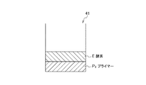
ウェル41,42,43内には、核酸増幅反応に必要な複数の試薬が所定の順序で積層されて固着化されている。図3に、各ウェル内に積層された試薬の固着層の例を示す。図3(A)はウェル41、(B)はウェル42、(C)はウェル43内に積層された試薬の固着層を示している。
In the
ウェル内に固着化する試薬は、核酸増幅反応において、増幅核酸鎖を得るために必要な試薬であって、具体的には、標的核酸鎖に相補的な塩基配列とされたオリゴヌクレオチドプライマー、核酸モノマー(dNTP)、酵素、反応緩衝液(バッファー)溶質などとされる。固着化する試薬は、これらのうち1あるいは2以上とできる。
また、これらの試薬を積層する順序は、例えば、「オリゴヌクレオチドプライマー、dNTP、酵素、バッファー溶質」の順や「バッファー溶質、酵素、dNTP、オリゴヌクレオチドプライマー」の順など、任意の順序とできる。
さらに、これらの試薬の一部、例えばプライマーとバッファー溶質や、プライマーとdNTPは混合されて固着化されてもよい。
ウェル内には、増幅核酸鎖を得るために必須ではないが、蛍光試薬(蛍光色素)やリン光試薬(リン光色素)などの増幅核酸鎖の検出及び定量のために必要な試薬を、必要に応じて固着化させておくこともできる。
The reagent immobilized in the well is a reagent necessary for obtaining an amplified nucleic acid chain in the nucleic acid amplification reaction, and specifically, an oligonucleotide primer, a nucleic acid having a base sequence complementary to the target nucleic acid chain Monomer (dNTP), enzyme, reaction buffer solution (buffer) solute, and the like. One or more of these reagents can be fixed.
The order of laminating these reagents may be any order such as “oligonucleotide primer, dNTP, enzyme, buffer solute” or “buffer solute, enzyme, dNTP, oligonucleotide primer”.
Furthermore, a part of these reagents, for example, a primer and a buffer solute, or a primer and dNTP may be mixed and immobilized.
Reagents necessary for detection and quantification of amplified nucleic acid strands such as fluorescent reagents (fluorescent dyes) and phosphorescent reagents (phosphorescent dyes) are necessary in the wells, although they are not essential for obtaining amplified nucleic acid strands. It can be fixed according to the condition.
ここでは、ウェル41,42,43内にまず酵素Eの固着層を形成し、その上層にオリゴヌクレオチドプライマー(以下、単に「プライマー」とも称する」)P1,P2,P3の固着層を積層する場合を図示している。後述するように、酵素固着層とプライマー固着層との間には、反応緩衝液溶質の固着層が積層されていてもよい(詳しくは後述)。
Here, an adhesion layer of enzyme E is first formed in the
プライマーP1,P2,P3は、同一の塩基配列を有するプライマーであってもよいが、マイクロチップAにおいて複数の標的核酸鎖の増幅を行う場合には、異なる塩基配列を有するプライマーとされる。例えば、マイクロチップAを用いて遺伝子型の判定を行う場合には、各遺伝子型の塩基配列に応じて異なる塩基配列を有するプライマーを、それぞれウェル41,42,43内に固着化させる。また、マイクロチップAを用いて感染病原体の判定を行う場合には、各ウイルスや微生物の遺伝子配列に応じて異なる塩基配列を有するプライマーを、同様に固着化させる。なお、各ウェルに固着される酵素Eは共通とする必要がある。
Primers P 1 , P 2 , and P 3 may be primers having the same base sequence, but when a plurality of target nucleic acid strands are amplified in microchip A, they are primers having different base sequences. The For example, when genotype determination is performed using the microchip A, primers having different base sequences according to the base sequence of each genotype are immobilized in the
このように、反応に必要な試薬を予めウェル内に固着化しておくことによって、マイクロチップAでは、残りの試薬と標的核酸鎖を含むサンプル溶液を導入口1から各ウェル内に供給するのみで反応を開始させることができる。このため、事前に混合する試薬の数を少なくし、混合する手間を省いて、簡便な分析が可能となる。
また、反応に必要な全ての試薬を予めウェル内に固着化しておけば、標的核酸鎖のみを含むサンプル溶液を供給するだけで反応を開始できるため、一層分析が簡便となる。
Thus, by fixing the reagents necessary for the reaction in the well in advance, in the microchip A, the sample solution containing the remaining reagent and the target nucleic acid chain is only supplied from the inlet 1 into each well. The reaction can be started. For this reason, the number of reagents to be mixed in advance is reduced, and the labor of mixing can be saved, thereby enabling simple analysis.
In addition, if all the reagents necessary for the reaction are immobilized in the well in advance, the reaction can be started simply by supplying a sample solution containing only the target nucleic acid chain, which makes the analysis easier.
加えて、マイクロチップAでは、残りの試薬と標的核酸鎖を含むサンプル溶液が各ウェル内に供給され、ウェル内に固着化された試薬が溶解されて初めて反応が開始されるため、反応時間を厳密に制御することができ、高い分析精度が得られる。 In addition, in the microchip A, the sample solution containing the remaining reagent and the target nucleic acid chain is supplied into each well, and the reaction starts only after the reagent immobilized in the well is dissolved. Strict control is possible and high analysis accuracy is obtained.
さらに、プライマーやdNTP、バッファー溶質に比べて温度変化や湿度変化、光等に不安定であり、活性の低下や失活が起こり易い酵素の固着層の上層に、反応系に過剰量加えられ、温度変化等にも比較的安定であるプライマーの固着層を積層することで、プライマー固着層によって酵素固着層を保護できる。このため、マイクロチップAの製造時及び保管時における温度変化等による酵素の活性低下や失活を防止することが可能となる。 Furthermore, it is unstable to temperature changes, humidity changes, light, etc. compared to primers, dNTPs, and buffer solutes. By laminating a primer fixing layer that is relatively stable against temperature changes and the like, the enzyme fixing layer can be protected by the primer fixing layer. For this reason, it becomes possible to prevent a decrease in activity or inactivation of the enzyme due to a temperature change during the manufacture and storage of the microchip A.
以上では、マイクロチップに縦横3例で合計9つのウェルを均等間隔で配設する場合を例に説明したが、ウェルの数や配設位置は任意とでき、ウェルの形状も図に示す円柱形状に限定されない。また、導入口1に導入されたサンプル溶液を各ウェル内に供給するための流路の構成も、図に示した主流路2及び分岐流路3の態様に限定されない。さらに、ここでは、導入口1等を基板層a1に形成する場合を説明したが、導入口1等は基板層a1及び基板層a2の両方に一部ずつ形成されていてもよい。マイクロチップを構成する基板層も2以上であってよい。 In the above description, the case where a total of nine wells are arranged on the microchip in three vertical and horizontal directions is described as an example. However, the number of wells and the arrangement positions can be arbitrary, and the well shape is also a cylindrical shape shown in the figure. It is not limited to. Further, the configuration of the channel for supplying the sample solution introduced into the inlet 1 into each well is not limited to the mode of the main channel 2 and the branch channel 3 shown in the figure. Further, here, the inlet 1 and the like has been described the case of forming the substrate layer a 1, etc. inlet 1 may be formed in portions on both of the substrate layers a 1 and the substrate layer a 2. There may also be two or more substrate layers constituting the microchip.
また、以上では、酵素の固着層の上層にプライマーの固着層を積層する場合を例に説明したが、試薬を積層する順序は任意であり、例えば、プライマーの固着層の上層に酵素の固着層を積層してもよい(図4参照)。この場合も、酵素固着層とプライマー固着層との間に、反応緩衝液溶質の固着層が積層されていてもよい(詳しくは後述)。 In the above, the case where the primer fixing layer is laminated on the enzyme fixing layer has been described as an example, but the order of stacking the reagents is arbitrary, for example, the enzyme fixing layer on the primer fixing layer. May be laminated (see FIG. 4). Also in this case, a reaction buffer solution solute fixing layer may be laminated between the enzyme fixing layer and the primer fixing layer (details will be described later).
プライマー固着層を上層に積層した場合には、導入口1から各ウェル内に供給されたサンプル溶液がプライマー固着層を溶解した後、酵素が溶解し反応が開始されるまでの間に、先に溶解したプライマーがウェル間で相互拡散(クロスコンタミネーション)するおそれがある。これに対して、酵素固着層を上層に積層した場合には、酵素固着層の溶解後、プライマー固着層が溶け始めるとすぐに反応が開始されるため、プライマーのクロスコンタミネーションを防止できる。 When the primer fixing layer is laminated on the upper layer, after the sample solution supplied from the inlet 1 into each well dissolves the primer fixing layer, the enzyme is dissolved and the reaction is started. There is a possibility that the dissolved primer may mutually diffuse (cross-contamination) between the wells. On the other hand, when the enzyme fixing layer is laminated on the upper layer, since the reaction starts as soon as the primer fixing layer starts to dissolve after the enzyme fixing layer is dissolved, the cross contamination of the primer can be prevented.
2.核酸増幅反応用マイクロチップの製造方法
続いて、図5に示すフローチャートを参照して、本発明に係るマイクロチップの製造方法を説明する。以下、上述のマイクロチップAを例に説明する。
2. Method for Producing Microchip for Nucleic Acid Amplification Reaction Next, a method for producing a microchip according to the present invention will be described with reference to the flowchart shown in FIG. Hereinafter, the above-described microchip A will be described as an example.
(2−1)基板層a1の成形
図5中、符号S1は、基板層a1の成形工程である。本工程では、基板層a1に、導入口1、主流路2、分岐流路3、ウェル41,42,43及び排出口5を成形する。基板層a1への導入口1等の成形は、例えば、ガラス製基板層のウェットエッチングやドライエッチングによって、あるいはプラスチック製基板層のナノインプリントや射出成型、切削加工によって行うことができる。
(2-1) Formation of Substrate Layer a 1 In FIG. 5, symbol S 1 is a formation step of the substrate layer a 1 . In this step, the inlet 1, the main channel 2, the branch channel 3, the
(2−2)ウェルへの酵素・プライマーの固着化
符号S2は、ウェルへの酵素の固着化工程である。また、符号S3は、ウェルへのプライマーの固着化工程である。工程S2,S3は、ウェル内に、反応に必要な複数の試薬を所定の順序で積層して固着化する工程(第一の工程)に相応する。
(2-2) Immobilization of Enzyme / Primer to Well Symbol S 2 is an enzyme immobilization step to the well. Further, reference numeral S 3 is a fixed step of the primer to the wells. Steps S 2 and S 3 correspond to a step (first step) in which a plurality of reagents necessary for the reaction are stacked and fixed in a predetermined order in the well.
ウェル内に固着化する試薬は、核酸増幅反応において、増幅核酸鎖を得るために必要な試薬であって、具体的には、標的核酸鎖に相補的な塩基配列とされたオリゴヌクレオチドプライマー、核酸モノマー(dNTP)、酵素、反応緩衝液(バッファー)溶質などとされる。固着化する試薬は、これらのうち1あるいは2以上とできる。
また、これらの試薬を積層する順序は、例えば、「プライマー、dNTP、酵素、バッファー溶質」の順や「バッファー溶質、酵素、dNTP、プライマー」の順など、任意の順序とできる。
さらに、これらの試薬の一部、例えばプライマーとバッファー溶質や、プライマーとdNTPは混合されて固着化されてもよい。
The reagent immobilized in the well is a reagent necessary for obtaining an amplified nucleic acid chain in the nucleic acid amplification reaction, and specifically, an oligonucleotide primer, a nucleic acid having a base sequence complementary to the target nucleic acid chain Monomer (dNTP), enzyme, reaction buffer solution (buffer) solute, and the like. One or more of these reagents can be fixed.
The order in which these reagents are stacked may be any order such as “primer, dNTP, enzyme, buffer solute” or “buffer solute, enzyme, dNTP, primer”.
Furthermore, a part of these reagents, for example, a primer and a buffer solute, or a primer and dNTP may be mixed and immobilized.
ここでは、ウェル41,42,43内に、工程S2において酵素Eの溶液を滴下して乾燥させ、工程S3においてそれぞれプライマーP1,P2,P3の溶液を滴下して乾燥させることにより、酵素の固着層の上層にプライマーの固着層を積層している。プライマーP1,P2,P3は、同一の塩基配列を有するプライマーであってもよいが、マイクロチップAにおいて複数の標的核酸鎖の増幅を行う場合には、異なる塩基配列を有するプライマーとされる。なお、各ウェルに固着される酵素Eは共通とする必要がある。 Here, in the well 41, a solution of the enzyme E dried dropwise in step S 2, respectively primers P 1 in step S 3, P 2, and dried by dropwise P 3 Thus, the primer fixing layer is laminated on the enzyme fixing layer. Primers P 1 , P 2 , and P 3 may be primers having the same base sequence, but when a plurality of target nucleic acid strands are amplified in microchip A, they are primers having different base sequences. The In addition, the enzyme E fixed to each well needs to be common.
試薬の固着化は、滴下した溶液を、風乾、真空乾燥あるいは凍結乾燥等によって、好ましくは緩徐に乾燥させることによって行う。酵素については、活性の低下や失活を防止するため、臨界点乾燥を行うことも有効である。 The reagent is fixed by air-drying, vacuum-drying, freeze-drying, or the like, preferably by slowly drying the dropped solution. For enzymes, it is also effective to perform critical point drying in order to prevent a decrease in activity or inactivation.
このとき、工程S2において固着化した酵素が、工程S3において滴下されるプライマー溶液によって再溶解される可能性がある。再溶解により、酵素とプライマーが混合されると、プライマーダイマーの増幅が生じる場合があるため好ましくない。
酵素とプライマーの混合を防止するため、工程S3では、マイクロチップを予め低温(−10℃程度)に保持し、滴下したプライマー溶液が凍結され、凍結乾燥されるようにすることが好ましい。
あるいは、マイクロチップを予め低温に保持し、水を滴下して凍結させた後にプライマー溶液を滴下して凍結乾燥を行い、さらに常温乾燥により氷の中間層を蒸発させる方法を用いてもよい。
さらに、より好適には、マイクロチップを予め低温に保持し、バッファー溶質溶液を滴下して凍結乾燥を行い、酵素Eの固着層の上層にバッファー溶質Bの固着層を積層し、その後、プライマー溶液を滴下して風乾、真空乾燥あるいは凍結乾燥を行ってもよい。これにより、各ウェル内には、酵素固着層とプライマー固着層との間に、バッファー溶質固着層が積層された3層構造が形成される(図6参照)。
なお、これらの方法は、プライマー固着層の上層に酵素固着層を積層する場合にも、プライマーの混合を防止するために採用され得る。
At this time, enzymes pinning in step S 2 is, there is likely to be re-dissolved by the primer solution is dropped in step S 3. If the enzyme and primer are mixed by re-dissolution, primer dimer amplification may occur, which is not preferable.
To prevent mixing of the enzyme and primer, the step S 3, and held in advance low temperature (about -10 ° C.) a microchip, the dropped primer solution is frozen, it is preferable to be freeze-dried.
Alternatively, a method may be used in which the microchip is held at a low temperature in advance, water is dropped to freeze it, a primer solution is dropped and freeze-dried, and the ice intermediate layer is evaporated by drying at room temperature.
More preferably, the microchip is kept at a low temperature in advance, the buffer solute solution is dropped and freeze-dried, and the buffer solute B fixing layer is laminated on the enzyme E fixing layer, and then the primer solution. May be dropped and air-dried, vacuum-dried or freeze-dried. Thus, a three-layer structure in which a buffer solute fixing layer is laminated between the enzyme fixing layer and the primer fixing layer is formed in each well (see FIG. 6).
These methods can also be employed to prevent mixing of the primer even when the enzyme fixing layer is laminated on the primer fixing layer.
(2−3)基板層a1,a2表面の活性化と貼り合せ
符号S4は、基板層a1,a2表面の活性化工程である。また、符号S5は、基板層a1,a2の貼り合せ工程である。工程S4,S5は、試薬が積層されて固着化された基板層の表面を活性化し、貼り合わせる工程(第二の工程)に相応する。
(2-3) Activation and Bonding of Surfaces of Substrate Layers a 1 and a 2 Reference numeral S 4 is an activation process of the surfaces of the substrate layers a 1 and a 2 . Reference numeral S 5 is a bonding step of the substrate layer a 1, a 2. Steps S 4 and S 5 correspond to a step (second step) in which the surface of the substrate layer on which the reagent is laminated and fixed is activated and bonded.
基板層a1と基板層a2の貼り合わせは、例えば、接着剤や粘着シートを用いた接合や熱融着、陽極接合、超音波接合により行うことができる。
また、基板層の表面を、酸素プラズマ処理又は真空紫外光処理により活性化して貼り合せる方法も採用できる。ポリジメチルシロキサン等のプラスチックとガラスは親和性が高く、表面を活性化処理して接触させると、ダングリングボンドが反応して強固な共有結合であるSi−O−Siシラノール結合を形成し、十分な強度の接合が得られる。酸素プラズマ処理又は真空紫外光処理は、基板層の材料に応じて適宜な条件を設定して行う。
The bonding of the substrate layer a 1 and the substrate layer a 2 can be performed, for example, by bonding using an adhesive or a pressure sensitive adhesive sheet, heat fusion, anodic bonding, or ultrasonic bonding.
Moreover, the method of activating and bonding the surface of a substrate layer by oxygen plasma processing or vacuum ultraviolet light processing is also employable. Plastics such as polydimethylsiloxane and glass have high affinity, and when the surface is activated and brought into contact, dangling bonds react to form a strong covalent bond, Si-O-Si silanol bond, Bonding with sufficient strength can be obtained. The oxygen plasma treatment or the vacuum ultraviolet light treatment is performed by setting appropriate conditions according to the material of the substrate layer.
このように、ウェルが形成された基板層のウェル内に、酵素とプライマーを別々に固着化して積層させることによって、これらを混合して固着させるのと異なり、溶液の滴下及び乾燥の最中にプライマーダイマーの増幅反応が進行することなく、試薬を固着化できる。 In this way, in the well of the substrate layer in which the well is formed, the enzyme and the primer are separately fixed and laminated, so that they are mixed and fixed, while the solution is dropped and dried. The reagent can be immobilized without the amplification reaction of the primer dimer.
さらに、温度変化や湿度変化、光等に不安定であり、活性の低下や失活が起こり易い酵素の固着層の上層に、反応系に過剰量加えられ、温度変化等にも比較的安定であるプライマーの固着層を積層することで、工程S4における加熱やプラズマあるいは紫外線の照射などから、酵素固着層を保護できる。すなわち、試薬を固着後の基板層の表面を酸素プラズマ処理又は真空紫外光処理により活性化する際もに、プライマー固着層が下層の酵素を保護するため、プラズマや紫外線の照射などによる酵素の活性低下や失活を防止することが可能となる。 In addition, it is unstable to temperature changes, humidity changes, light, etc., and is added to the reaction system in an excessive amount on the upper layer of the enzyme-fixing layer, where activity is likely to decrease or deactivate. by stacking a pinned layer of a primer, irradiation etc. heating or plasma or ultraviolet in the step S 4, to protect the enzyme fixed layer. That is, when the surface of the substrate layer after fixing the reagent is activated by oxygen plasma treatment or vacuum ultraviolet light treatment, the primer adhesion layer protects the underlying enzyme, so that the activity of the enzyme by plasma or ultraviolet irradiation etc. It is possible to prevent a decrease and inactivation.
以上では、酵素の固着層の上層にプライマーの固着層を積層する場合を例に説明したが、試薬を積層する順序は任意であり、例えば、プライマーの固着層の上層に酵素の固着層を積層してもよい(図4参照)。この場合も、酵素固着層とプライマー固着層との間に、反応緩衝液溶質の固着層を積層することが有効となる。 In the above, the case where the primer adhesion layer is laminated on the enzyme adhesion layer has been described as an example. However, the order in which the reagents are laminated is arbitrary, for example, the enzyme adhesion layer is laminated on the primer adhesion layer. You may do (refer FIG. 4). Also in this case, it is effective to laminate a reaction buffer solution solute fixing layer between the enzyme fixing layer and the primer fixing layer.
本発明に係る核酸増幅反応用マイクロチップによれば、簡便な方法で高精度な分析を行うことができる。そのため、本発明に係る核酸増幅反応用マイクロチップは、遺伝子型判定や感染病原体判定などのためのマイクロチップ型の核酸増幅装置に好適に用いられ得る。 According to the microchip for nucleic acid amplification reaction according to the present invention, highly accurate analysis can be performed by a simple method. Therefore, the microchip for nucleic acid amplification reaction according to the present invention can be suitably used for a microchip type nucleic acid amplification apparatus for genotype determination, infectious pathogen determination, and the like.
A 核酸増幅反応用マイクロチップ
E 酵素
P1,P2,P3 プライマー
1 導入口
2 主流路
3 分岐流路
41,42,43 ウェル
5 排出口
A Microchip for nucleic acid amplification reaction E Enzyme P 1 , P 2 , P 3 Primer 1 Inlet 2 Main channel 3
Claims (5)
核酸増幅反応の反応場となる複数のウェルと、
導入口から導入される液体を各ウェル内に供給する流路と、が配設され、
各ウェル内に、反応に必要な複数の試薬が所定の順序で積層されて固着化されており、
オリゴヌクレオチドプライマーの固着層が、酵素の固着層よりも上層に積層された核酸増幅反応用マイクロチップ。 An inlet through which liquid is introduced from the outside;
A plurality of wells serving as reaction fields for nucleic acid amplification reaction;
And a flow path for supplying the liquid introduced from the introduction port into each well,
In each well, a plurality of reagents necessary for the reaction are laminated and fixed in a predetermined order ,
A nucleic acid amplification reaction microchip in which an oligonucleotide primer fixing layer is laminated above an enzyme fixing layer .
前記試薬が積層されて固着化された基板層の表面を活性化し、貼り合わせる第二の工程を含み、
前記第一の工程において、前記ウェル内に、酵素溶液を滴下して乾燥した後、オリゴヌクレオチドプライマー溶液を滴下して乾燥する手順を含む核酸増幅反応用マイクロチップの製造方法。 A first step of laminating and immobilizing a plurality of reagents necessary for the reaction in a predetermined order in the well of the substrate layer in which a plurality of wells serving as a reaction field of a nucleic acid amplification reaction are formed ;
A second step of activating and bonding the surface of the substrate layer on which the reagent is laminated and fixed;
A method for producing a microchip for nucleic acid amplification reaction, comprising: a step of dropping an enzyme solution into the well and drying it, and then dropping an oligonucleotide primer solution into the well in the first step .
Priority Applications (6)
| Application Number | Priority Date | Filing Date | Title |
|---|---|---|---|
| JP2010027200A JP5691187B2 (en) | 2010-02-10 | 2010-02-10 | Microchip for nucleic acid amplification reaction and method for producing the same |
| PCT/JP2011/000543 WO2011099251A1 (en) | 2010-02-10 | 2011-02-01 | Microchip for nucleic acid amplification reaction and and process for production thereof |
| CN201180008396.9A CN102741408B (en) | 2010-02-10 | 2011-02-01 | Microchip for nucleic acid amplification reaction and manufacturing method thereof |
| SG2012054862A SG182706A1 (en) | 2010-02-10 | 2011-02-01 | Microchip for nucleic acid amplification reaction and a method of manufacturing the same |
| EP11742001.8A EP2535408B1 (en) | 2010-02-10 | 2011-02-01 | Microchip for nucleic acid amplification reaction and and process for production thereof |
| US13/576,898 US20120309084A1 (en) | 2010-02-10 | 2011-02-01 | Microchip for nucleic acid amplification reaction and a method of manufacturing the same |
Applications Claiming Priority (1)
| Application Number | Priority Date | Filing Date | Title |
|---|---|---|---|
| JP2010027200A JP5691187B2 (en) | 2010-02-10 | 2010-02-10 | Microchip for nucleic acid amplification reaction and method for producing the same |
Publications (2)
| Publication Number | Publication Date |
|---|---|
| JP2011160728A JP2011160728A (en) | 2011-08-25 |
| JP5691187B2 true JP5691187B2 (en) | 2015-04-01 |
Family
ID=44367539
Family Applications (1)
| Application Number | Title | Priority Date | Filing Date |
|---|---|---|---|
| JP2010027200A Active JP5691187B2 (en) | 2010-02-10 | 2010-02-10 | Microchip for nucleic acid amplification reaction and method for producing the same |
Country Status (6)
| Country | Link |
|---|---|
| US (1) | US20120309084A1 (en) |
| EP (1) | EP2535408B1 (en) |
| JP (1) | JP5691187B2 (en) |
| CN (1) | CN102741408B (en) |
| SG (1) | SG182706A1 (en) |
| WO (1) | WO2011099251A1 (en) |
Families Citing this family (10)
| Publication number | Priority date | Publication date | Assignee | Title |
|---|---|---|---|---|
| JP5786295B2 (en) * | 2010-06-22 | 2015-09-30 | ソニー株式会社 | Nucleic acid isothermal amplification microchip, method for producing the same, and nucleic acid isothermal amplification method |
| IN2014MN01628A (en) | 2012-03-08 | 2015-05-15 | Sony Corp | |
| JP6074911B2 (en) | 2012-05-10 | 2017-02-08 | ソニー株式会社 | Microchip for nucleic acid analysis |
| AU2013267227B2 (en) | 2012-05-31 | 2017-03-02 | The University Of North Carolina At Chapel Hill | Dissolution guided wetting of structured surfaces |
| JP2014071056A (en) * | 2012-10-01 | 2014-04-21 | Sony Corp | Optical measuring apparatus and optical measuring microchip |
| JP7131836B2 (en) * | 2017-03-29 | 2022-09-06 | コーネル・ユニバーシティー | Devices, processes, and systems for determining nucleic acid sequence, expression, copy number, or methylation changes using a combination of nuclease, ligase, polymerase, and sequencing reactions |
| CN211905402U (en) * | 2019-11-22 | 2020-11-10 | 京东方科技集团股份有限公司 | Detection chip and detection system |
| TWI814324B (en) * | 2022-03-31 | 2023-09-01 | 國立臺灣大學 | A portable device integrated with all-in-one lamp system for nucleic acid amplification and method thereof |
| WO2025143227A1 (en) * | 2023-12-28 | 2025-07-03 | Zacros株式会社 | Examination device including reaction unit coated with reactive substance |
| JP2026000704A (en) * | 2024-06-18 | 2026-01-06 | キヤノン株式会社 | Array Plate Structure |
Family Cites Families (16)
| Publication number | Priority date | Publication date | Assignee | Title |
|---|---|---|---|---|
| US6001568A (en) * | 1992-10-26 | 1999-12-14 | Institut Belka | Solid medium for amplification and expression of nucleic acids as colonies |
| US5599660A (en) * | 1993-01-19 | 1997-02-04 | Pharmacia Biotech Inc. | Method and preparation for sequential delivery of wax-embedded, inactivated biological and chemical reagents |
| US5658443A (en) * | 1993-07-23 | 1997-08-19 | Matsushita Electric Industrial Co., Ltd. | Biosensor and method for producing the same |
| AU2871095A (en) * | 1994-06-24 | 1996-01-19 | University Of Houston, The | Encapsulated pcr reagents |
| US5856174A (en) * | 1995-06-29 | 1999-01-05 | Affymetrix, Inc. | Integrated nucleic acid diagnostic device |
| US6391622B1 (en) * | 1997-04-04 | 2002-05-21 | Caliper Technologies Corp. | Closed-loop biochemical analyzers |
| ES2309022T3 (en) * | 1997-12-24 | 2008-12-16 | Cepheid | DEVICE AND PROCEDURE FOR LISIS. |
| EP1173557A1 (en) * | 1999-04-23 | 2002-01-23 | Nexttec GmbH | Method for encapsulating macromolecules and/or particles and use thereof |
| JP4355210B2 (en) * | 2001-11-30 | 2009-10-28 | フルイディグム コーポレイション | Microfluidic device and method of using microfluidic device |
| JP2004219199A (en) | 2003-01-14 | 2004-08-05 | Teruo Fujii | Chemical micro-device |
| EP1716249A2 (en) * | 2003-12-31 | 2006-11-02 | Applera Corporation, Applied Biosystems Group | Quantitative amplification and detection of small numbers of target polynucleotides |
| DE102004021822B3 (en) * | 2004-04-30 | 2005-11-17 | Siemens Ag | Method and arrangement for DNA amplification by means of PCR using dry reagents |
| US20070259348A1 (en) * | 2005-05-03 | 2007-11-08 | Handylab, Inc. | Lyophilized pellets |
| JP2007043998A (en) * | 2005-08-11 | 2007-02-22 | Tosoh Corp | Improved microfluidic chip |
| JP4202407B2 (en) * | 2006-01-23 | 2008-12-24 | パナソニック株式会社 | Pyrophosphate sensor and SNP typing sensor using the same |
| JP2008304356A (en) * | 2007-06-08 | 2008-12-18 | Toppan Printing Co Ltd | Lab-on-chip reagent sealing structure and lab-on-chip |
-
2010
- 2010-02-10 JP JP2010027200A patent/JP5691187B2/en active Active
-
2011
- 2011-02-01 EP EP11742001.8A patent/EP2535408B1/en not_active Not-in-force
- 2011-02-01 WO PCT/JP2011/000543 patent/WO2011099251A1/en not_active Ceased
- 2011-02-01 US US13/576,898 patent/US20120309084A1/en not_active Abandoned
- 2011-02-01 SG SG2012054862A patent/SG182706A1/en unknown
- 2011-02-01 CN CN201180008396.9A patent/CN102741408B/en not_active Expired - Fee Related
Also Published As
| Publication number | Publication date |
|---|---|
| SG182706A1 (en) | 2012-08-30 |
| EP2535408A4 (en) | 2013-09-25 |
| JP2011160728A (en) | 2011-08-25 |
| EP2535408B1 (en) | 2014-11-12 |
| CN102741408A (en) | 2012-10-17 |
| US20120309084A1 (en) | 2012-12-06 |
| CN102741408B (en) | 2014-03-19 |
| EP2535408A1 (en) | 2012-12-19 |
| WO2011099251A1 (en) | 2011-08-18 |
Similar Documents
| Publication | Publication Date | Title |
|---|---|---|
| JP5691187B2 (en) | Microchip for nucleic acid amplification reaction and method for producing the same | |
| US20220186325A1 (en) | Systems for sample analysis | |
| JP7293236B2 (en) | Method and system for automated sample processing | |
| US8092999B2 (en) | Biological sample reaction chip and biological sample reaction method | |
| JP5786295B2 (en) | Nucleic acid isothermal amplification microchip, method for producing the same, and nucleic acid isothermal amplification method | |
| Ramalingam et al. | Real-time PCR array chip with capillary-driven sample loading and reactor sealing for point-of-care applications | |
| US20090129198A1 (en) | Intra-microchannel mixing method and apparatus | |
| JP2013526867A (en) | Reaction vessel for PCR apparatus and method for performing PCR | |
| Kulkarni et al. | A review on recent advancements in chamber-based microfluidic PCR devices | |
| CN102399867A (en) | Nucleic acid quantification method and microchip for nucleic acid amplification reaction | |
| JP2013090586A (en) | Microchip for nucleic acid amplification reaction and method of producing the same | |
| US9545630B2 (en) | Method for fabricating microchip for nucleic acid amplification reaction | |
| Shu-Mi et al. | An integrated nucleic acid extraction microchip for real-time PCR micro total analysis | |
| US20230285965A1 (en) | Microfluidic device for detecting nucleic acids | |
| Pham et al. | Fabrication of 3D continuous-flow reverse-transcription polymerase chain reaction microdevice integrated with on-chip fluorescence detection for semi-quantitative assessment of gene expression | |
| US20240367171A1 (en) | Microfluidic device | |
| US20240216916A1 (en) | Microfluidic device | |
| WO2026006318A1 (en) | Point-of-care bioassay systems and methods of making and using the same | |
| JP2009198183A (en) | Biosample analyzing plate | |
| JP2011139641A (en) | Reaction substrate production method and reaction substrate production device |
Legal Events
| Date | Code | Title | Description |
|---|---|---|---|
| A621 | Written request for application examination |
Free format text: JAPANESE INTERMEDIATE CODE: A621 Effective date: 20130118 |
|
| A131 | Notification of reasons for refusal |
Free format text: JAPANESE INTERMEDIATE CODE: A131 Effective date: 20140610 |
|
| A521 | Request for written amendment filed |
Free format text: JAPANESE INTERMEDIATE CODE: A523 Effective date: 20140805 |
|
| TRDD | Decision of grant or rejection written | ||
| A01 | Written decision to grant a patent or to grant a registration (utility model) |
Free format text: JAPANESE INTERMEDIATE CODE: A01 Effective date: 20150106 |
|
| A61 | First payment of annual fees (during grant procedure) |
Free format text: JAPANESE INTERMEDIATE CODE: A61 Effective date: 20150119 |
|
| R151 | Written notification of patent or utility model registration |
Ref document number: 5691187 Country of ref document: JP Free format text: JAPANESE INTERMEDIATE CODE: R151 |
|
| R250 | Receipt of annual fees |
Free format text: JAPANESE INTERMEDIATE CODE: R250 |
|
| R250 | Receipt of annual fees |
Free format text: JAPANESE INTERMEDIATE CODE: R250 |
|
| R250 | Receipt of annual fees |
Free format text: JAPANESE INTERMEDIATE CODE: R250 |