JP5681192B2 - Method for applying atomic layer deposition coatings on porous non-ceramic substrates - Google Patents
Method for applying atomic layer deposition coatings on porous non-ceramic substrates Download PDFInfo
- Publication number
- JP5681192B2 JP5681192B2 JP2012530934A JP2012530934A JP5681192B2 JP 5681192 B2 JP5681192 B2 JP 5681192B2 JP 2012530934 A JP2012530934 A JP 2012530934A JP 2012530934 A JP2012530934 A JP 2012530934A JP 5681192 B2 JP5681192 B2 JP 5681192B2
- Authority
- JP
- Japan
- Prior art keywords
- substrate
- porous non
- porous
- reactor
- polymer substrate
- Prior art date
- Legal status (The legal status is an assumption and is not a legal conclusion. Google has not performed a legal analysis and makes no representation as to the accuracy of the status listed.)
- Expired - Fee Related
Links
Images


Classifications
-
- C—CHEMISTRY; METALLURGY
- C23—COATING METALLIC MATERIAL; COATING MATERIAL WITH METALLIC MATERIAL; CHEMICAL SURFACE TREATMENT; DIFFUSION TREATMENT OF METALLIC MATERIAL; COATING BY VACUUM EVAPORATION, BY SPUTTERING, BY ION IMPLANTATION OR BY CHEMICAL VAPOUR DEPOSITION, IN GENERAL; INHIBITING CORROSION OF METALLIC MATERIAL OR INCRUSTATION IN GENERAL
- C23C—COATING METALLIC MATERIAL; COATING MATERIAL WITH METALLIC MATERIAL; SURFACE TREATMENT OF METALLIC MATERIAL BY DIFFUSION INTO THE SURFACE, BY CHEMICAL CONVERSION OR SUBSTITUTION; COATING BY VACUUM EVAPORATION, BY SPUTTERING, BY ION IMPLANTATION OR BY CHEMICAL VAPOUR DEPOSITION, IN GENERAL
- C23C16/00—Chemical coating by decomposition of gaseous compounds, without leaving reaction products of surface material in the coating, i.e. chemical vapour deposition [CVD] processes
- C23C16/04—Coating on selected surface areas, e.g. using masks
- C23C16/045—Coating cavities or hollow spaces, e.g. interior of tubes; Infiltration of porous substrates
-
- C—CHEMISTRY; METALLURGY
- C08—ORGANIC MACROMOLECULAR COMPOUNDS; THEIR PREPARATION OR CHEMICAL WORKING-UP; COMPOSITIONS BASED THEREON
- C08J—WORKING-UP; GENERAL PROCESSES OF COMPOUNDING; AFTER-TREATMENT NOT COVERED BY SUBCLASSES C08B, C08C, C08F, C08G or C08H
- C08J9/00—Working-up of macromolecular substances to porous or cellular articles or materials; After-treatment thereof
- C08J9/36—After-treatment
- C08J9/365—Coating
-
- C—CHEMISTRY; METALLURGY
- C23—COATING METALLIC MATERIAL; COATING MATERIAL WITH METALLIC MATERIAL; CHEMICAL SURFACE TREATMENT; DIFFUSION TREATMENT OF METALLIC MATERIAL; COATING BY VACUUM EVAPORATION, BY SPUTTERING, BY ION IMPLANTATION OR BY CHEMICAL VAPOUR DEPOSITION, IN GENERAL; INHIBITING CORROSION OF METALLIC MATERIAL OR INCRUSTATION IN GENERAL
- C23C—COATING METALLIC MATERIAL; COATING MATERIAL WITH METALLIC MATERIAL; SURFACE TREATMENT OF METALLIC MATERIAL BY DIFFUSION INTO THE SURFACE, BY CHEMICAL CONVERSION OR SUBSTITUTION; COATING BY VACUUM EVAPORATION, BY SPUTTERING, BY ION IMPLANTATION OR BY CHEMICAL VAPOUR DEPOSITION, IN GENERAL
- C23C16/00—Chemical coating by decomposition of gaseous compounds, without leaving reaction products of surface material in the coating, i.e. chemical vapour deposition [CVD] processes
- C23C16/22—Chemical coating by decomposition of gaseous compounds, without leaving reaction products of surface material in the coating, i.e. chemical vapour deposition [CVD] processes characterised by the deposition of inorganic material, other than metallic material
- C23C16/30—Deposition of compounds, mixtures or solid solutions, e.g. borides, carbides, nitrides
- C23C16/40—Oxides
- C23C16/403—Oxides of aluminium, magnesium or beryllium
-
- C—CHEMISTRY; METALLURGY
- C23—COATING METALLIC MATERIAL; COATING MATERIAL WITH METALLIC MATERIAL; CHEMICAL SURFACE TREATMENT; DIFFUSION TREATMENT OF METALLIC MATERIAL; COATING BY VACUUM EVAPORATION, BY SPUTTERING, BY ION IMPLANTATION OR BY CHEMICAL VAPOUR DEPOSITION, IN GENERAL; INHIBITING CORROSION OF METALLIC MATERIAL OR INCRUSTATION IN GENERAL
- C23C—COATING METALLIC MATERIAL; COATING MATERIAL WITH METALLIC MATERIAL; SURFACE TREATMENT OF METALLIC MATERIAL BY DIFFUSION INTO THE SURFACE, BY CHEMICAL CONVERSION OR SUBSTITUTION; COATING BY VACUUM EVAPORATION, BY SPUTTERING, BY ION IMPLANTATION OR BY CHEMICAL VAPOUR DEPOSITION, IN GENERAL
- C23C16/00—Chemical coating by decomposition of gaseous compounds, without leaving reaction products of surface material in the coating, i.e. chemical vapour deposition [CVD] processes
- C23C16/44—Chemical coating by decomposition of gaseous compounds, without leaving reaction products of surface material in the coating, i.e. chemical vapour deposition [CVD] processes characterised by the method of coating
- C23C16/455—Chemical coating by decomposition of gaseous compounds, without leaving reaction products of surface material in the coating, i.e. chemical vapour deposition [CVD] processes characterised by the method of coating characterised by the method used for introducing gases into reaction chamber or for modifying gas flows in reaction chamber
- C23C16/45523—Pulsed gas flow or change of composition over time
- C23C16/45525—Atomic layer deposition [ALD]
- C23C16/45544—Atomic layer deposition [ALD] characterized by the apparatus
- C23C16/45546—Atomic layer deposition [ALD] characterized by the apparatus specially adapted for a substrate stack in the ALD reactor
-
- C—CHEMISTRY; METALLURGY
- C23—COATING METALLIC MATERIAL; COATING MATERIAL WITH METALLIC MATERIAL; CHEMICAL SURFACE TREATMENT; DIFFUSION TREATMENT OF METALLIC MATERIAL; COATING BY VACUUM EVAPORATION, BY SPUTTERING, BY ION IMPLANTATION OR BY CHEMICAL VAPOUR DEPOSITION, IN GENERAL; INHIBITING CORROSION OF METALLIC MATERIAL OR INCRUSTATION IN GENERAL
- C23C—COATING METALLIC MATERIAL; COATING MATERIAL WITH METALLIC MATERIAL; SURFACE TREATMENT OF METALLIC MATERIAL BY DIFFUSION INTO THE SURFACE, BY CHEMICAL CONVERSION OR SUBSTITUTION; COATING BY VACUUM EVAPORATION, BY SPUTTERING, BY ION IMPLANTATION OR BY CHEMICAL VAPOUR DEPOSITION, IN GENERAL
- C23C16/00—Chemical coating by decomposition of gaseous compounds, without leaving reaction products of surface material in the coating, i.e. chemical vapour deposition [CVD] processes
- C23C16/44—Chemical coating by decomposition of gaseous compounds, without leaving reaction products of surface material in the coating, i.e. chemical vapour deposition [CVD] processes characterised by the method of coating
- C23C16/455—Chemical coating by decomposition of gaseous compounds, without leaving reaction products of surface material in the coating, i.e. chemical vapour deposition [CVD] processes characterised by the method of coating characterised by the method used for introducing gases into reaction chamber or for modifying gas flows in reaction chamber
- C23C16/45523—Pulsed gas flow or change of composition over time
- C23C16/45525—Atomic layer deposition [ALD]
- C23C16/45555—Atomic layer deposition [ALD] applied in non-semiconductor technology
-
- C—CHEMISTRY; METALLURGY
- C23—COATING METALLIC MATERIAL; COATING MATERIAL WITH METALLIC MATERIAL; CHEMICAL SURFACE TREATMENT; DIFFUSION TREATMENT OF METALLIC MATERIAL; COATING BY VACUUM EVAPORATION, BY SPUTTERING, BY ION IMPLANTATION OR BY CHEMICAL VAPOUR DEPOSITION, IN GENERAL; INHIBITING CORROSION OF METALLIC MATERIAL OR INCRUSTATION IN GENERAL
- C23C—COATING METALLIC MATERIAL; COATING MATERIAL WITH METALLIC MATERIAL; SURFACE TREATMENT OF METALLIC MATERIAL BY DIFFUSION INTO THE SURFACE, BY CHEMICAL CONVERSION OR SUBSTITUTION; COATING BY VACUUM EVAPORATION, BY SPUTTERING, BY ION IMPLANTATION OR BY CHEMICAL VAPOUR DEPOSITION, IN GENERAL
- C23C16/00—Chemical coating by decomposition of gaseous compounds, without leaving reaction products of surface material in the coating, i.e. chemical vapour deposition [CVD] processes
- C23C16/44—Chemical coating by decomposition of gaseous compounds, without leaving reaction products of surface material in the coating, i.e. chemical vapour deposition [CVD] processes characterised by the method of coating
- C23C16/54—Apparatus specially adapted for continuous coating
- C23C16/545—Apparatus specially adapted for continuous coating for coating elongated substrates
-
- D—TEXTILES; PAPER
- D06—TREATMENT OF TEXTILES OR THE LIKE; LAUNDERING; FLEXIBLE MATERIALS NOT OTHERWISE PROVIDED FOR
- D06C—FINISHING, DRESSING, TENTERING OR STRETCHING TEXTILE FABRICS
- D06C29/00—Finishing or dressing, of textile fabrics, not provided for in the preceding groups
-
- D—TEXTILES; PAPER
- D06—TREATMENT OF TEXTILES OR THE LIKE; LAUNDERING; FLEXIBLE MATERIALS NOT OTHERWISE PROVIDED FOR
- D06M—TREATMENT, NOT PROVIDED FOR ELSEWHERE IN CLASS D06, OF FIBRES, THREADS, YARNS, FABRICS, FEATHERS OR FIBROUS GOODS MADE FROM SUCH MATERIALS
- D06M11/00—Treating fibres, threads, yarns, fabrics or fibrous goods made from such materials, with inorganic substances or complexes thereof; Such treatment combined with mechanical treatment, e.g. mercerising
- D06M11/32—Treating fibres, threads, yarns, fabrics or fibrous goods made from such materials, with inorganic substances or complexes thereof; Such treatment combined with mechanical treatment, e.g. mercerising with oxygen, ozone, ozonides, oxides, hydroxides or percompounds; Salts derived from anions with an amphoteric element-oxygen bond
- D06M11/36—Treating fibres, threads, yarns, fabrics or fibrous goods made from such materials, with inorganic substances or complexes thereof; Such treatment combined with mechanical treatment, e.g. mercerising with oxygen, ozone, ozonides, oxides, hydroxides or percompounds; Salts derived from anions with an amphoteric element-oxygen bond with oxides, hydroxides or mixed oxides; with salts derived from anions with an amphoteric element-oxygen bond
- D06M11/45—Oxides or hydroxides of elements of Groups 3 or 13 of the Periodic Table; Aluminates
-
- D—TEXTILES; PAPER
- D06—TREATMENT OF TEXTILES OR THE LIKE; LAUNDERING; FLEXIBLE MATERIALS NOT OTHERWISE PROVIDED FOR
- D06M—TREATMENT, NOT PROVIDED FOR ELSEWHERE IN CLASS D06, OF FIBRES, THREADS, YARNS, FABRICS, FEATHERS OR FIBROUS GOODS MADE FROM SUCH MATERIALS
- D06M11/00—Treating fibres, threads, yarns, fabrics or fibrous goods made from such materials, with inorganic substances or complexes thereof; Such treatment combined with mechanical treatment, e.g. mercerising
- D06M11/51—Treating fibres, threads, yarns, fabrics or fibrous goods made from such materials, with inorganic substances or complexes thereof; Such treatment combined with mechanical treatment, e.g. mercerising with sulfur, selenium, tellurium, polonium or compounds thereof
- D06M11/53—Treating fibres, threads, yarns, fabrics or fibrous goods made from such materials, with inorganic substances or complexes thereof; Such treatment combined with mechanical treatment, e.g. mercerising with sulfur, selenium, tellurium, polonium or compounds thereof with hydrogen sulfide or its salts; with polysulfides
-
- D—TEXTILES; PAPER
- D06—TREATMENT OF TEXTILES OR THE LIKE; LAUNDERING; FLEXIBLE MATERIALS NOT OTHERWISE PROVIDED FOR
- D06M—TREATMENT, NOT PROVIDED FOR ELSEWHERE IN CLASS D06, OF FIBRES, THREADS, YARNS, FABRICS, FEATHERS OR FIBROUS GOODS MADE FROM SUCH MATERIALS
- D06M11/00—Treating fibres, threads, yarns, fabrics or fibrous goods made from such materials, with inorganic substances or complexes thereof; Such treatment combined with mechanical treatment, e.g. mercerising
- D06M11/58—Treating fibres, threads, yarns, fabrics or fibrous goods made from such materials, with inorganic substances or complexes thereof; Such treatment combined with mechanical treatment, e.g. mercerising with nitrogen or compounds thereof, e.g. with nitrides
-
- D—TEXTILES; PAPER
- D06—TREATMENT OF TEXTILES OR THE LIKE; LAUNDERING; FLEXIBLE MATERIALS NOT OTHERWISE PROVIDED FOR
- D06M—TREATMENT, NOT PROVIDED FOR ELSEWHERE IN CLASS D06, OF FIBRES, THREADS, YARNS, FABRICS, FEATHERS OR FIBROUS GOODS MADE FROM SUCH MATERIALS
- D06M23/00—Treatment of fibres, threads, yarns, fabrics or fibrous goods made from such materials, characterised by the process
- D06M23/005—Applying monomolecular films on textile products like fibres, threads or fabrics
-
- C—CHEMISTRY; METALLURGY
- C08—ORGANIC MACROMOLECULAR COMPOUNDS; THEIR PREPARATION OR CHEMICAL WORKING-UP; COMPOSITIONS BASED THEREON
- C08J—WORKING-UP; GENERAL PROCESSES OF COMPOUNDING; AFTER-TREATMENT NOT COVERED BY SUBCLASSES C08B, C08C, C08F, C08G or C08H
- C08J2201/00—Foams characterised by the foaming process
- C08J2201/02—Foams characterised by the foaming process characterised by mechanical pre- or post-treatments
- C08J2201/038—Use of an inorganic compound to impregnate, bind or coat a foam, e.g. waterglass
-
- H10P14/2922—
-
- H10P14/2924—
-
- H10P14/3411—
-
- Y—GENERAL TAGGING OF NEW TECHNOLOGICAL DEVELOPMENTS; GENERAL TAGGING OF CROSS-SECTIONAL TECHNOLOGIES SPANNING OVER SEVERAL SECTIONS OF THE IPC; TECHNICAL SUBJECTS COVERED BY FORMER USPC CROSS-REFERENCE ART COLLECTIONS [XRACs] AND DIGESTS
- Y10—TECHNICAL SUBJECTS COVERED BY FORMER USPC
- Y10T—TECHNICAL SUBJECTS COVERED BY FORMER US CLASSIFICATION
- Y10T428/00—Stock material or miscellaneous articles
- Y10T428/13—Hollow or container type article [e.g., tube, vase, etc.]
- Y10T428/1352—Polymer or resin containing [i.e., natural or synthetic]
- Y10T428/1362—Textile, fabric, cloth, or pile containing [e.g., web, net, woven, knitted, mesh, nonwoven, matted, etc.]
-
- Y—GENERAL TAGGING OF NEW TECHNOLOGICAL DEVELOPMENTS; GENERAL TAGGING OF CROSS-SECTIONAL TECHNOLOGIES SPANNING OVER SEVERAL SECTIONS OF THE IPC; TECHNICAL SUBJECTS COVERED BY FORMER USPC CROSS-REFERENCE ART COLLECTIONS [XRACs] AND DIGESTS
- Y10—TECHNICAL SUBJECTS COVERED BY FORMER USPC
- Y10T—TECHNICAL SUBJECTS COVERED BY FORMER US CLASSIFICATION
- Y10T428/00—Stock material or miscellaneous articles
- Y10T428/13—Hollow or container type article [e.g., tube, vase, etc.]
- Y10T428/1352—Polymer or resin containing [i.e., natural or synthetic]
- Y10T428/1376—Foam or porous material containing
-
- Y—GENERAL TAGGING OF NEW TECHNOLOGICAL DEVELOPMENTS; GENERAL TAGGING OF CROSS-SECTIONAL TECHNOLOGIES SPANNING OVER SEVERAL SECTIONS OF THE IPC; TECHNICAL SUBJECTS COVERED BY FORMER USPC CROSS-REFERENCE ART COLLECTIONS [XRACs] AND DIGESTS
- Y10—TECHNICAL SUBJECTS COVERED BY FORMER USPC
- Y10T—TECHNICAL SUBJECTS COVERED BY FORMER US CLASSIFICATION
- Y10T428/00—Stock material or miscellaneous articles
- Y10T428/249921—Web or sheet containing structurally defined element or component
- Y10T428/249953—Composite having voids in a component [e.g., porous, cellular, etc.]
- Y10T428/249955—Void-containing component partially impregnated with adjacent component
- Y10T428/249958—Void-containing component is synthetic resin or natural rubbers
-
- Y—GENERAL TAGGING OF NEW TECHNOLOGICAL DEVELOPMENTS; GENERAL TAGGING OF CROSS-SECTIONAL TECHNOLOGIES SPANNING OVER SEVERAL SECTIONS OF THE IPC; TECHNICAL SUBJECTS COVERED BY FORMER USPC CROSS-REFERENCE ART COLLECTIONS [XRACs] AND DIGESTS
- Y10—TECHNICAL SUBJECTS COVERED BY FORMER USPC
- Y10T—TECHNICAL SUBJECTS COVERED BY FORMER US CLASSIFICATION
- Y10T442/00—Fabric [woven, knitted, or nonwoven textile or cloth, etc.]
- Y10T442/20—Coated or impregnated woven, knit, or nonwoven fabric which is not [a] associated with another preformed layer or fiber layer or, [b] with respect to woven and knit, characterized, respectively, by a particular or differential weave or knit, wherein the coating or impregnation is neither a foamed material nor a free metal or alloy layer
- Y10T442/2861—Coated or impregnated synthetic organic fiber fabric
Landscapes
- Chemical & Material Sciences (AREA)
- Engineering & Computer Science (AREA)
- Chemical Kinetics & Catalysis (AREA)
- Materials Engineering (AREA)
- Organic Chemistry (AREA)
- Textile Engineering (AREA)
- General Chemical & Material Sciences (AREA)
- Mechanical Engineering (AREA)
- Metallurgy (AREA)
- Health & Medical Sciences (AREA)
- Inorganic Chemistry (AREA)
- Medicinal Chemistry (AREA)
- Polymers & Plastics (AREA)
- Separation Using Semi-Permeable Membranes (AREA)
- Chemical Vapour Deposition (AREA)
- Laminated Bodies (AREA)
- Coating Of Shaped Articles Made Of Macromolecular Substances (AREA)
- Physical Or Chemical Processes And Apparatus (AREA)
- Filtering Materials (AREA)
- Catalysts (AREA)
Description
(関連出願の相互参照)
本出願は、共に2009年9月22日に出願された米国特許仮出願第61/244,713号及び同第61/244,696号の利益を主張し、当該特許出願の開示は参照によりその全体が本明細書に組み込まれる。
(Cross-reference of related applications)
This application claims the benefit of US provisional applications 61 / 244,713 and 61 / 244,696, both filed September 22, 2009, the disclosure of which is hereby incorporated by reference. The entirety is incorporated herein.
(発明の分野)
本発明は、処理された多孔性非セラミック基材の製造に関し、より詳細には、これを達成するための流入原子層堆積法に関する。
(Field of Invention)
The present invention relates to the manufacture of treated porous non-ceramic substrates and, more particularly, to an inflow atomic layer deposition process to achieve this.
原子層堆積(ALD)法は、もともと薄膜エレクトロルミネセンス(TFEL)フラットパネルディスプレイ用に開発された。ALDに対する関心は、原子レベルで膜の組成及び厚さを制御して、非常に薄くて柔軟性のある膜を製造するその能力に起因して、ケイ素ベースマイクロ電子機器(ウエハ)を中心に長年にわたって著しく高まっている。ALDはまた、自己制限的で連続的な表面反応プロセスにより高アスペクト比表面をコーティングするその能力でよく知られている。しかしながら、こうした高アスペクト比表面をコーティングするプロセスの能力は、反応性ガスがこうした領域に拡散して、次の前駆体を加える前にこのガスが完全に放出されるのに必要な時間という大きな課題を抱えている。この拡散問題は、この技術が多孔性材料まで拡張されるのを大きく妨げてきた。 Atomic layer deposition (ALD) methods were originally developed for thin film electroluminescence (TFEL) flat panel displays. Interest in ALD has long been around silicon-based microelectronics (wafers) due to its ability to control film composition and thickness at the atomic level to produce very thin and flexible films. Has risen significantly over time. ALD is also well known for its ability to coat high aspect ratio surfaces by a self-limiting, continuous surface reaction process. However, the ability of the process to coat such high aspect ratio surfaces is a major challenge of the time required for the reactive gas to diffuse into these areas and be completely released before the next precursor is added. Have This diffusion problem has greatly hindered this technology from being extended to porous materials.
本発明は、全てのガスがコーティングされるべき多孔性非セラミック材料を貫通することを求めることにより、上で述べられた拡散問題に対処する。これにより、対象となる材料の表面を出たり入ったりして拡散する必要性が排除されるので、所要時間が減少し、内側表面の不完全なコーティング被覆(coating coverage)が起こる可能性が最小限に抑えられる。 The present invention addresses the diffusion problem described above by requiring that all gases penetrate the porous non-ceramic material to be coated. This eliminates the need to diffuse in and out of the surface of the material of interest, reducing the time required and minimizing the possibility of incomplete coating coverage of the inner surface. It can be suppressed to the limit.
一態様において、本発明は、多孔性非セラミック基材上にコンフォーマルコーティングを堆積させる方法を提供し、この方法は、
入口と出口とを有する反応器を提供する工程と、
多孔性非セラミック基材が入口を出口から分離するように、少なくとも1つの多孔性非セラミック基材の少なくとも一部を配置する工程と、
第1及び第2の反応性ガスを多孔性非セラミック基材を通して出口まで流して、多孔性非セラミック基材の内部表面における一連の2回以上の自己制限的な反応を行って、内部表面の少なくとも一部の上にコンフォーマルコーティングを形成するように、入口における第1及び第2の反応性ガスの順次導入の少なくとも1回の繰り返しを実施する工程と、を含む。
In one aspect, the present invention provides a method of depositing a conformal coating on a porous non-ceramic substrate, the method comprising:
Providing a reactor having an inlet and an outlet;
Disposing at least a portion of at least one porous non-ceramic substrate such that the porous non-ceramic substrate separates the inlet from the outlet;
The first and second reactive gases are flowed through the porous non-ceramic substrate to the outlet to perform a series of two or more self-limiting reactions on the inner surface of the porous non-ceramic substrate. Performing at least one iteration of sequential introduction of the first and second reactive gases at the inlet to form a conformal coating on at least a portion.
定義
本開示に関連して、用語「多孔性」とは、基材が、少なくともガスが通過することができるのに十分な開口部(即ち「細孔」)を含むことを意味する。
Definitions In the context of this disclosure, the term “porous” means that the substrate includes sufficient openings (ie, “pores”) to allow at least gas to pass therethrough.
用語「微小多孔性」とは、ガスが基材の細孔内を通過することができるように、基材が、1,000マイクロメートル以下の中央断面内寸(「メジアン細孔径」、例えば、円筒状細孔の場合の直径)を有する細孔を含むことを意味する。好ましい微小多孔性基材は、0.01マイクロメートル以上1,000マイクロメートル以下、より好ましくは0.1マイクロメートル以上100マイクロメートル以下、更により好ましくは0.2マイクロメートル以上20マイクロメートル以下、最も好ましくは0.3マイクロメートル以上3マイクロメートル以下、又は更に1マイクロメートルのメジアン細孔径を有する細孔を含む。本明細書を通して用いられる場合、メジアン細孔径は、ASTM規格F316−03に記載されているバブルポイント圧測定法を用いて決定された。 The term “microporous” means that the substrate has a median cross-sectional dimension (“median pore diameter”) of 1,000 micrometers or less, such that gas can pass through the pores of the substrate. Means a pore having a diameter) in the case of a cylindrical pore. Preferred microporous substrates are 0.01 micrometers or more and 1,000 micrometers or less, more preferably 0.1 micrometers or more and 100 micrometers or less, even more preferably 0.2 micrometers or more and 20 micrometers or less, Most preferably, it contains pores having a median pore diameter of 0.3 to 3 micrometers, or even 1 micrometer. As used throughout this specification, the median pore size was determined using the bubble point pressure measurement method described in ASTM Standard F316-03.
用語「非多孔性」とは、基材が細孔を実質的に含まないことを意味する。 The term “non-porous” means that the substrate is substantially free of pores.
用語「非セラミック」とは、コンフォーマルコーティングの堆積の前の基材に関し、基材が、無機金属酸化物、金属窒化物、金属炭化物、又はその他のセラミック物質を実質的に含まないことを意味する。好ましい「非セラミック」基材は、セラミック物質を完全に含まない、より好ましくは、繊維性有機材料(例えば、ポリマー繊維、天然繊維、炭素繊維等)から本質的になる、更により好ましくは、有機材料のみからなる。 The term “non-ceramic” refers to a substrate prior to deposition of a conformal coating, meaning that the substrate is substantially free of inorganic metal oxides, metal nitrides, metal carbides, or other ceramic materials. To do. Preferred “non-ceramic” substrates are completely free of ceramic materials, more preferably consist essentially of fibrous organic materials (eg polymer fibers, natural fibers, carbon fibers, etc.), even more preferably organic It consists only of materials.
用語「コンフォーマルコーティング」とは、下にある基材の形状に良好に接着してこれとぴったり合う、材料の比較的薄いコーティングを意味する。 The term “conformal coating” means a relatively thin coating of material that adheres well to and conforms to the shape of the underlying substrate.
本方法は、非セラミック基材の内部表面の少なくとも一部の上にコンフォーマルコーティングを提供する。本方法の多くの好都合な実施形態では、コンフォーマルコーティングは、金属酸化物、金属窒化物、金属硫化物、又はこれらの組み合わせを含む。これらの例の金属は、様々な種類のものであってもよいが、ケイ素、チタン、アルミニウム、ジルコニウム、及びイットリウムが特に適していると考えられる。好ましくは、金属は、ケイ素、チタン、又はアルミニウムであり、より好ましくは、金属はアルミニウムである。いくつかの好ましい実施形態では、コンフォーマルコーティングは酸化アルミニウムを含む。 The method provides a conformal coating on at least a portion of the interior surface of the non-ceramic substrate. In many advantageous embodiments of the method, the conformal coating comprises a metal oxide, metal nitride, metal sulfide, or a combination thereof. These examples of metals may be of various types, but silicon, titanium, aluminum, zirconium, and yttrium are considered particularly suitable. Preferably, the metal is silicon, titanium or aluminum, more preferably the metal is aluminum. In some preferred embodiments, the conformal coating comprises aluminum oxide.
原子層制御成長技術を介して適用され得るコーティングが好ましい。コーティングのうち、かかる方法で容易に適用されるのは、二成分物質、即ち、QxRyの形の物質であり、Q及びRは異なる原子を表し、x及びyは、静電気的に中性の物質を反映する数字である。好適な二成分物質は、種々の無機酸化物(例えば、二酸化ケイ素、及びジルコニア、アルミナ、シリカ、酸化ホウ素、イットリア、酸化亜鉛、酸化マグネシウム、TiO2等などの金属酸化物など)、無機窒化物(例えば、窒化ケイ素、AlN及びBNなど)、無機硫化物(例えば、硫化ガリウム、硫化タングステン及び硫化モリブデンなど)、並びに無機リン酸である。更に、コバルト、パラジウム、プラチナ、亜鉛、レニウム、モリブデン、アンチモン、セレン、タリウム、クロム、プラチナ、ルテニウム、イリジウム、ゲルマニウム及びタングステンなどの種々の金属コーティングが有用である。 Coatings that can be applied via atomic layer controlled growth techniques are preferred. Of the coating, being easily applied in such a way, two-component materials, i.e., a Q x R y form of material, Q and R represent different atoms, x and y are electrostatically Medium It is a number that reflects a sex substance. Suitable binary materials include various inorganic oxides (eg, silicon dioxide and metal oxides such as zirconia, alumina, silica, boron oxide, yttria, zinc oxide, magnesium oxide, TiO 2 etc.), inorganic nitrides (For example, silicon nitride, AlN, and BN), inorganic sulfides (for example, gallium sulfide, tungsten sulfide, and molybdenum sulfide), and inorganic phosphoric acid. In addition, various metal coatings such as cobalt, palladium, platinum, zinc, rhenium, molybdenum, antimony, selenium, thallium, chromium, platinum, ruthenium, iridium, germanium and tungsten are useful.
自己制限的で連続的なコーティングの適用の有用な議論は、例えば、米国特許第6,713,177号、同第6,913,827号、及び同第6,613,383号に見出すことができる。 Useful discussions of the application of self-limiting and continuous coatings can be found, for example, in US Pat. Nos. 6,713,177, 6,913,827, and 6,613,383. it can.
ALD反応の分野に精通している者は、上述のコンフォーマルコーティングを生成するために、第1及び第2の反応性ガスのどちらが本発明の方法による自己制限的な反応にとって適切な選択であるのかを容易に決定することができる。例えば、アルミニウム含有化合物が所望の場合、トリメチルアルミニウム又はトリイソブチルアルミニウムガスを、2種類の反応性ガスの1つとして使用してもよい。所望のアルミニウム含有化合物が酸化アルミニウムの場合、その繰り返しにおけるもう1つの反応性ガスは、水蒸気又はオゾンであり得る。所望のアルミニウム含有化合物が窒化アルミニウムの場合、その繰り返しにおけるもう一方の反応性ガスは、アンモニア又は窒素/水素プラズマであり得る。所望のアルミニウム含有化合物が硫化アルミニウムの場合、その繰り返しにおけるもう一方の反応性ガスは、硫化水素であり得る。 Those familiar with the field of ALD reactions are either the first or second reactive gas is a suitable choice for the self-limiting reaction according to the method of the present invention to produce the conformal coating described above. Can be easily determined. For example, if an aluminum-containing compound is desired, trimethylaluminum or triisobutylaluminum gas may be used as one of two reactive gases. If the desired aluminum-containing compound is aluminum oxide, another reactive gas in the iteration can be water vapor or ozone. If the desired aluminum-containing compound is aluminum nitride, the other reactive gas in the iteration can be ammonia or a nitrogen / hydrogen plasma. When the desired aluminum-containing compound is aluminum sulfide, the other reactive gas in the repetition can be hydrogen sulfide.
同様に、アルミニウム化合物の代わりにケイ素化合物がコンフォーマルコーティングにおいて望ましい場合、2種類の反応性ガスの1つは、例えば、テトラメチルシラン又は四塩化ケイ素であり得る。上記で組み込まれた参照は、所望の最終結果に応じた好適な反応性ガスに関する更なるガイダンスを提供する。 Similarly, if a silicon compound is desired in the conformal coating instead of an aluminum compound, one of the two reactive gases can be, for example, tetramethylsilane or silicon tetrachloride. The references incorporated above provide further guidance on suitable reactive gases depending on the desired end result.
本方法の単一繰り返しは、ある目的に適している場合がある分子単層を形成することができるが、本方法の多くの有用な実施形態は、実施工程を少なくとも8回、10回、20回、又はそれ以上の繰り返しだけ繰り返す。各繰り返しは、コンフォーマルコーティングに厚みを加える。したがって、いくつかの実施形態では、繰り返しの回数は、多孔性非セラミック基材に所定の気孔率又は平均内部細孔径が得られるように選択される。いくつかの実施形態では、実施する繰り返しの回数を制御することによって、所望の気孔率(例えば、所望の平均内部細孔径)を達成するために、コンフォーマルコーティングを用いて多孔性非セラミック基材の気孔率を制御可能に低減する(例えば、基材の見掛け孔径を制御する)ことができる。例えば、コンフォーマルコーティングは、多孔性非セラミック基材の気孔率を5%以上、25%以上、又は更に50%以上低減することができる。同様に、基材が細孔を含む場合、コンフォーマルコーティングは、平均内部細孔径を5nm以上低減してもよい。 Although a single iteration of the method can form a molecular monolayer that may be suitable for certain purposes, many useful embodiments of the method may perform at least 8 times, 10 times, 20 steps. Repeat only once or more times. Each iteration adds thickness to the conformal coating. Thus, in some embodiments, the number of iterations is selected to provide a predetermined porosity or average internal pore size for the porous non-ceramic substrate. In some embodiments, a porous non-ceramic substrate is used with a conformal coating to achieve a desired porosity (eg, a desired average internal pore size) by controlling the number of repetitions performed. Can be controllably reduced (for example, the apparent pore diameter of the substrate can be controlled). For example, conformal coatings can reduce the porosity of porous non-ceramic substrates by 5% or more, 25% or more, or even 50% or more. Similarly, if the substrate contains pores, the conformal coating may reduce the average internal pore diameter by 5 nm or more.
ある用途では、本方法を適用する目的は、基材の内部表面上に親水性を得るためである。こうした用途では、上記工程は、例えば、72ダイン/cm(0.072N/m)(一般に用いられる親水性の定義)といった目標とする表面エネルギーが達成されるまで繰り返される。更に、出口に最も近い多孔性非セラミック基材の外部表面は、72ダイン/cm(0.072N/m)を超える表面エネルギーを有することもまた望ましくあり得、そのような場合には、上記実施工程は、目標が達成されるまで繰り返される必要がある。反対に、いくつかの特定の実施形態では、内部表面を親水性とする一方で、出口に最も近い多孔性非セラミック基材の外部表面を疎水性(例えば、72ダイン/cm(0.072N/m)未満)のままとするのが望ましい場合がある。 In some applications, the purpose of applying the method is to obtain hydrophilicity on the internal surface of the substrate. In such applications, the above process is repeated until a target surface energy of, for example, 72 dynes / cm 2 (0.072 N / m) (a commonly used definition of hydrophilicity) is achieved. Furthermore, it may also be desirable for the outer surface of the porous non-ceramic substrate closest to the outlet to have a surface energy greater than 72 dynes / cm (0.072 N / m), in which case the implementation described above The process needs to be repeated until the goal is achieved. Conversely, in some specific embodiments, the inner surface is hydrophilic while the outer surface of the porous non-ceramic substrate closest to the outlet is hydrophobic (eg, 72 dynes / cm 2 (0.072 N / It may be desirable to leave it below m) .
本発明の方法は、基材に損傷を与えない任意の有用な温度で行うことができる。いくつかの実施形態では、本方法は、例えば、約300℃以下、約200℃以下、約70℃以下、又は更に約60℃以下の温度で行われる。 The method of the present invention can be carried out at any useful temperature that does not damage the substrate. In some embodiments, the method is performed at a temperature of, for example, about 300 ° C. or less, about 200 ° C. or less, about 70 ° C. or less, or even about 60 ° C. or less.
本発明の多くの有用な実施形態では、多孔性非セラミック基材は多孔性ポリマー基材である。そのような実施形態では、第1及び第2の反応性ガスの導入は、基材又は細孔の熱変形を引き起こさないように、多孔性ポリマー基材の融解温度を下回る温度で行われるのが好都合な場合が多い。例えば、本発明の方法は、基材の構造的一体性にとって望ましい場合は、例えば、300℃未満で行われることができる。 In many useful embodiments of the present invention, the porous non-ceramic substrate is a porous polymer substrate. In such embodiments, the introduction of the first and second reactive gases may occur at a temperature below the melting temperature of the porous polymer substrate so as not to cause thermal deformation of the substrate or pores. Often convenient. For example, the method of the present invention can be performed at, for example, less than 300 ° C., if desired for the structural integrity of the substrate.
多孔性ポリマー基材を使用する場合、熱誘起相分離(TIPS)、蒸気誘起相分離(VIPS)などの誘起相分離法、又は、米国特許出願公開第2008/0241503号に記載の相分離を誘起する共キャスティング法(co-casting method)によって多孔性にされた基材を使用することが好都合であり得る。 When a porous polymer substrate is used, induced phase separation methods such as thermally induced phase separation (TIPS), vapor induced phase separation (VIPS), or phase separation described in US Patent Application Publication No. 2008/0241503 are induced. It may be advantageous to use a substrate that has been made porous by a co-casting method.
ポリマー材料から多孔性基材を形成する他の方法は、本発明を用いる当業者には明らかであろう。例えば、ステッチボンドウェブ又はヒドロエンタングルド(hydro-entangled)ウェブなどの短繊維不織布、並びにメルトブローンウェブ又はスパンボンドウェブなどのスパンレイド不織布を使用してもよい。他の用途では、天然繊維、炭素繊維、融解された金属、又はガラスなどの非ポリマー非セラミック材料が好適であり得る。 Other methods of forming a porous substrate from a polymeric material will be apparent to those skilled in the art using the present invention. For example, short fiber nonwovens such as stitchbond webs or hydro-entangled webs, and spunlaid nonwovens such as meltblown webs or spunbond webs may be used. In other applications, non-polymeric, non-ceramic materials such as natural fibers, carbon fibers, melted metals, or glass may be suitable.
本発明は、少なくとも1つの多孔性非セラミック基材の少なくとも一部を、多孔性ポリマー基材が反応器の入口を出口から分離するように配置することを必要とするが、これは、多孔性非セラミック基材の物理トポロジーを制限するものではない。最終用途に応じて、多孔性非セラミック基材は、平坦、プリーツ状、管状、細い中空糸の形態、単一若しくは束にされた(potted)繊維カートリッジ、又は任意のその他の有用な形体であってもよい。 The present invention requires that at least a portion of at least one porous non-ceramic substrate be positioned such that the porous polymer substrate separates the reactor inlet from the outlet, It does not limit the physical topology of the non-ceramic substrate. Depending on the end use, the porous non-ceramic substrate may be flat, pleated, tubular, in the form of a thin hollow fiber, a single or potted fiber cartridge, or any other useful form. May be.
本方法を用いる場合、少なくとも第2の多孔性非セラミック基材の少なくとも一部を、第2の多孔性非セラミック基材もまた入口を出口から分離するように配置することが可能であり、また好都合である場合がある。3つ以上の多孔性非セラミック基材を、本方法を用いて同時に成功裏に処理することができることが証明されている。 When using the method, at least a portion of the second porous non-ceramic substrate can be positioned such that the second porous non-ceramic substrate also separates the inlet from the outlet, and May be convenient. It has been demonstrated that more than two porous non-ceramic substrates can be successfully processed simultaneously using this method.
多孔性非セラミック基材はバッチ処理で処理されることができ、又は多孔性非セラミック基材は不定長の材料のウェブの形態であってもよく、また配置手段は、ロールツーロールプロセスを可能とするタイプであり得る。かかるロールツーロールプロセスは、ステップアンドリピートタイプのものであってもよく、又は連続移動プロセスであり得る。 The porous non-ceramic substrate can be processed in a batch process, or the porous non-ceramic substrate may be in the form of a web of indefinite length material, and the placement means allows for a roll-to-roll process It can be a type. Such a roll-to-roll process may be of the step and repeat type or may be a continuous transfer process.
本方法の1つの好都合な変形は、反応器自体が最終消費者を対象とした製品の中に組み込まれるようなバッチ反応器の中でプロセスを実行することである。例えば、反応器はフィルタ本体の形態であってもよく、フィルタ本体、及びコンフォーマルコーティングがその場で提供される多孔性非セラミックは、最終消費者に販売されるフィルタの一部であり得る。いくつかの実施形態では、複数のフィルタを、直列又は並列に接続された流路の中で同時に処理することができる。 One advantageous variant of the method is to run the process in a batch reactor such that the reactor itself is incorporated into a product intended for the end consumer. For example, the reactor may be in the form of a filter body, and the filter body and the porous non-ceramic provided with a conformal coating in situ may be part of the filter sold to the end consumer. In some embodiments, multiple filters can be processed simultaneously in flow paths connected in series or in parallel.
多くの好都合な実施形態では、多孔性非セラミック基材は、コンフォーマルコーティングがひとたび内部表面に適用されてしまえば、その最終用途に適している。しかしながら、コンフォーマルコーティングに二次加工を実施するのが有用な場合がある。二次加工は、反応器の中又は別の好都合な装置の中のいずれかで行われることができる。例えば、多孔性非セラミック基材の内側表面が親水性にされている場合でさえも、多孔性非セラミック基材の外側表面の一方又は両方を、最終的なサイズコーティングで処理して疎水性にすることができる。この技術は、例えば、液体水を通さずにガス及び水蒸気だけを通す必要がある気管内チューブのための通気フィルタを調製するために用いることができる。 In many advantageous embodiments, the porous non-ceramic substrate is suitable for its end use once the conformal coating has been applied to the inner surface. However, it may be useful to perform a secondary process on the conformal coating. Secondary processing can take place either in the reactor or in another convenient apparatus. For example, even if the inner surface of the porous non-ceramic substrate is made hydrophilic, one or both of the outer surfaces of the porous non-ceramic substrate can be treated with a final size coating to make it hydrophobic. can do. This technique can be used, for example, to prepare a ventilation filter for an endotracheal tube that needs to pass only gas and water vapor without passing liquid water.
実施することができる別の二次加工は、コンフォーマルコーティングに化学部分をグラフトすることである。例えば、ポリエチレンイミン配位基及びビグアニド配位基から選択されるグラフト化配位基(grafted ligand group)を用いた本発明によるコンフォーマルコーティングを有する多孔性非セラミック基材を提供するために外挿することができる技術の議論は、米国特許出願公開第2010/0075131号及び同第2010/0075560号に見出すことができる。放射又は粒子エネルギーによるグラフティングを用いて、シランなどの他の有用な配位子、抗体などの生物活性部分、キレート剤、及び触媒コーティングを結合させることもまた可能である。 Another secondary processing that can be performed is to graft a chemical moiety onto the conformal coating. For example, extrapolated to provide a porous non-ceramic substrate having a conformal coating according to the present invention using a grafted ligand group selected from polyethyleneimine and biguanide coordination groups A discussion of techniques that can be found can be found in US Patent Application Publication Nos. 2010/0075131 and 2010/0075560. It is also possible to bind other useful ligands such as silanes, bioactive moieties such as antibodies, chelating agents, and catalytic coatings using radiant or particle energy grafting.
本発明の方法によりコンフォーマルコーティングが施された多孔性非セラミック基材は、多くの用途に役立つ。例えば、液体及びガスの両方の濾過は、処理された基材を使用することによって促進され得る。例えば、水の濾過に関しては、多孔性フィルタ要素に親水性を提供するコンフォーマルコーティングは、抵抗を減少させて、フィルタを通る流れを促進するように作用し得る。これは、フィルタが重力流条件下及び低圧仕様で使用される場合に特に有用である。細孔の物理的寸法及び間隔、並びにコンフォーマルコーティングは、特定の効果を得るように選択され得る。例えば、多孔性非セラミック基材は、液体が一定圧力未満で開口部を通過するのを防止することができる繊維間の間隔を有する(即ち、液体抵抗)、微細なメルトブローン繊維又はナノ繊維ウェブであり得る。 Porous non-ceramic substrates that have been conformally coated by the method of the present invention are useful for many applications. For example, both liquid and gas filtration can be facilitated by using a treated substrate. For example, with respect to water filtration, a conformal coating that provides hydrophilicity to the porous filter element may act to reduce resistance and facilitate flow through the filter. This is particularly useful when the filter is used under gravity flow conditions and in low pressure specifications. The physical dimensions and spacing of the pores, as well as the conformal coating, can be selected to obtain a specific effect. For example, a porous non-ceramic substrate is a fine meltblown fiber or nanofibrous web that has an interfiber spacing (ie, liquid resistance) that can prevent liquid from passing through the opening below a certain pressure. possible.
上述のようなある種のコンフォーマルコーティングを使用して、本発明に従って作製されるフィルタ要素の中にスケール沈積が起こるのを低減することができる。これは、二次加工において、スケール物質との相溶性を低減するように設計されたコーティングを適用することによって達成され得る。銀又は他の抗菌性材料もまた、多孔性非セラミック基材の表面上に細菌膜(bio-film)が形成され、増殖するのを防止するのを助けるように、又は濾過される液体を処理するように、記載されているコーティングの一部と結合することができる。更に、例えば、金属酸化物コーティング自体が、二次処理なしに、かかるフィルタがより高い使用温度で作動するのを可能にして、温水又は水/蒸気を含む用途を潜在的に可能にすることができると考えられている。 Certain conformal coatings as described above can be used to reduce the occurrence of scale deposition in filter elements made in accordance with the present invention. This can be achieved by applying a coating designed to reduce the compatibility with the scale material in the secondary processing. Silver or other antibacterial materials also treat the liquid to be filtered or filtered to help prevent the growth and growth of a bio-film on the surface of the porous non-ceramic substrate As such, it can be combined with a portion of the described coating. Further, for example, the metal oxide coating itself can potentially enable applications involving hot water or water / steam, allowing such filters to operate at higher service temperatures without secondary treatment. It is considered possible.
水及び水溶液以外の他の液体の濾過も同様に、本発明による処理された基材の利益を享受することができる。例えば、高い使用温度を可能にするコンフォーマルコーティングは、加熱された油の濾過を可能にすることができる。一部のコンフォーマルコーティングは、酸性又は高pH環境において耐化学性をもたらすことができる。様々な汚染化学物質を制限又は吸収して「深層濾過」を提供することができるように適合させる本発明の変更が、それぞれに与えられた数個のフィルタ要素を有するフィルタを提供することができる。 Filtration of liquids other than water and aqueous solutions can likewise benefit from the treated substrate according to the present invention. For example, a conformal coating that allows for a high service temperature can allow for the filtration of heated oil. Some conformal coatings can provide chemical resistance in acidic or high pH environments. Modifications of the present invention adapted to limit or absorb various pollutant chemicals to provide “depth filtration” can provide a filter with several filter elements each given. .
上述の処理は、空気濾過にも役立つ。上述のように、コンフォーマルコーティングは、空気濾過用途においても同様に、高い使用温度を可能にすることができる。十分な繰り返しにより、例えば、ディーゼル排気の濾過に関して十分な耐熱性を有する空気フィルタを、本発明に従って提供することができることが想到される。二次的な抗菌、吸着、又は触媒コーティングは、例えば、メルトブローン基材を、生物医学的用途のための又は個人的保護装置としてのマスクとしての使用に適合させることができる。例えば、ナノ金触媒は、コンフォーマルコーティングに結合されて、このコンフォーマルコーティングを保護マスクの一酸化炭素除去剤として機能させるようにすることができる。 The above treatment is also useful for air filtration. As mentioned above, conformal coatings can enable high service temperatures in air filtration applications as well. It is envisaged that with sufficient repetition, an air filter having sufficient heat resistance, for example, for filtering diesel exhaust, can be provided according to the present invention. Secondary antimicrobial, adsorption, or catalytic coatings can, for example, adapt meltblown substrates for use as a mask for biomedical applications or as a personal protection device. For example, the nanogold catalyst can be bonded to a conformal coating, allowing the conformal coating to function as a carbon monoxide remover for the protective mask.
濾過の他に、本発明の方法は、多孔性断熱材の処理に役立つ。二次加工で適用される抗菌性材料は、例えば、湿潤環境における生物学的汚染の可能性を低減することができる。十分な繰り返しにより、難燃性を有する断熱材を提供することができると考えられる。 In addition to filtration, the method of the present invention is useful for the treatment of porous insulation. Antimicrobial materials applied in secondary processing can, for example, reduce the potential for biological contamination in a humid environment. It is thought that the heat insulating material which has a flame retardance can be provided by sufficient repetition.
更に、本発明による多孔性非セラミック基材、特に二次加工で生体適合性層が付与された多孔性非セラミック基材を、種々の医学的用途用の組織スキャフォールドとして使用することができる。 Furthermore, porous non-ceramic substrates according to the present invention, in particular porous non-ceramic substrates provided with a biocompatible layer by secondary processing, can be used as tissue scaffolds for various medical applications.
本発明に従って調製された特定の多孔性非セラミック基材は、いくつかの用途に関して特に適している場合がある。例えば、親水性にされたポリフッ化ビニリデン(PVDF)は、濾過、アニオン交換膜のための基材、気管内チューブのための通気フィルタ、及び食品安全のための試料調製装置における用途に特に適している可能性があり、親水性にされたナイロンは、タンパク質精製及び浄水(例えば、4級アンモニウム塩シランの付着を介する)における用途に特に適している可能性があり、また親水性にされた不織布は、感染予防のためのクリーニングワイプス、深層濾過、及び食品安全のための大きな(ample)調製装置などの用途に特に適している可能性がある。 Certain porous non-ceramic substrates prepared according to the present invention may be particularly suitable for some applications. For example, hydrophilicized polyvinylidene fluoride (PVDF) is particularly suitable for use in filtration, substrates for anion exchange membranes, aeration filters for endotracheal tubes, and sample preparation equipment for food safety. Nylon rendered hydrophilic may be particularly suitable for use in protein purification and water purification (eg, through the attachment of quaternary ammonium salt silanes), and hydrophilicized nonwovens May be particularly suitable for applications such as cleaning wipes for infection prevention, depth filtration, and ample preparation equipment for food safety.
ここで図1を参照すると、本発明と共に使用するのに適している反応器20の断面図が示されている。図示される反応器20は、本発明に関連したバッチ処理に適しており、入口24と出口26とを備える反応器本体22を有する。入口24及び出口26は、入口24でD1の方向に導入された反応性ガスが、多孔性非セラミック基材30a、30b、及び30cの一部の全てを必ず通過して、出口26に向けてD2の方向に方向付けられるように、多孔性非セラミック基材30a、30b、及び30cの3つの個別部分の対向側にある。図の実施形態では、基材30a、30b、及び30cの一部は、両面フランジ32a、32b、32c、及び32dによってそれらの縁部で好都合に把持されているが、この目的のために他の手段を用いることができることが当業者には認識されよう。
Referring now to FIG. 1, a cross-sectional view of a
本発明の目的及び利点は、以下の実施例によって更に例示されるが、これらの実施例において列挙された特定の材料及びその量は、他の諸条件及び詳細と同様に、本発明を過度に制限するものと解釈されるべきではない。 The objects and advantages of this invention are further illustrated by the following examples, which are not intended to limit the particular materials and amounts listed in these examples, as well as other conditions and details. It should not be construed as limiting.
試料の表面エネルギーの試験方法
ALDコーティングされた多孔性非セラミック基材のいくつかの試料を、実施例と共に以下に記載する。試料の表面エネルギーについて論じる場合、以下の方法で測定値を得た。様々な濃度のダインテスト溶液(dyne test solutions)を得た。ASTM規格D−2578に準拠した30〜70ダイン/cm(0.030〜0.070N/m)の濃度範囲の溶液を、Jemmco,LLC(Mequon,WI)から購入した。表1に示される量のMgCl2・6H2Oを十分な脱イオン水と混合することによって、72〜86ダイン/cm(0.072〜0.086N/m)の濃度範囲の溶液を調製し、合計で25グラムの溶液を作製した。
Test Method for Sample Surface Energy Several samples of ALD coated porous non-ceramic substrates are described below with examples. When discussing the surface energy of the sample, measurements were obtained in the following manner. Various concentrations of dyne test solutions were obtained. Solutions in the concentration range of 30-70 dynes / cm 2 (0.030-0.070 N / m) in accordance with ASTM standard D-2578 were purchased from Jemco, LLC (Mequon, WI). A solution with a concentration range of 72-86 dynes / cm 2 (0.072-0.086 N / m) was prepared by mixing the amount of MgCl 2 .6H 2 O shown in Table 1 with sufficient deionized water. A total of 25 grams of solution was made.
これらのダインテスト溶液を使用して、以下の通りにテストする必要がある基材を、ASTM規格ASTM D7541−09のセクション12に記載の落下試験に供した。 Using these dyne test solutions, substrates that need to be tested as follows were subjected to drop testing as described in section 12 of ASTM standard ASTM D7541-09.
基材Aの調製
米国特許第5,120,594号(Mrozinski)及び同第4,726,989号(Mrozinski)に概ね記載されている通りに、熱誘導相分離(TIPS)法を用いて微小多孔性ポリプロピレン基材を調製した。より詳細には、核化ポリプロピレン/鉱油ブレンドを調製し、滑らかで冷却されたキャスティングホイールに押し出し、そこでこの材料は固液相分離を生じた。この材料の連続基材を収集し、1,1,1−トリクロロエタン槽を通過させて鉱油を除去した。こうして形成された微小多孔性ポリプロピレン基材は、244μm(9.6ミル)の厚さを有した。次に、微小多孔性ポリプロピレン基材をASTM規格F316−03に準拠してテストし、0.90μmのバブルポイント孔径に応じた69.7kPa(10.11psi)のイソプロピルアルコールバブルポイント圧を有することが分かった。更に、気孔率は83.3%であり、純水透過性能は477L/(m2−h−kPa)であった。基材は強疎水性であり、29ダイン/cm(0.029N/m)の表面エネルギーを有していた。
Preparation of Substrate A Using the thermally induced phase separation (TIPS) method as described generally in US Pat. Nos. 5,120,594 (Mrozinski) and 4,726,989 (Mrozinski) A porous polypropylene substrate was prepared. More specifically, a nucleated polypropylene / mineral oil blend was prepared and extruded onto a smooth and cooled casting wheel where the material caused solid-liquid phase separation. A continuous substrate of this material was collected and passed through a 1,1,1-trichloroethane bath to remove mineral oil. The microporous polypropylene substrate thus formed had a thickness of 244 μm (9.6 mils). The microporous polypropylene substrate is then tested according to ASTM standard F316-03 and has an isopropyl alcohol bubble point pressure of 69.7 kPa (10.11 psi) corresponding to a bubble point pore size of 0.90 μm. I understood. Furthermore, the porosity was 83.3% and the pure water permeation performance was 477 L / (m 2 -h-kPa). The substrate was strongly hydrophobic and had a surface energy of 29 dynes / cm 2 (0.029 N / m) .
基材Bの調製
別の微小多孔性基材を、Solvay Advanced Polymers,L.L.C.(Alpharetta,GA)から商品名及び等級表示(grade designation)HALAR 902で市販のエチレン−クロロトリフルオロエチレンコポリマー(ECTFE)から調製した。これは、米国特許出願公開第2009/0067807号に概ね記載されているTIPSプロセスによって行われた。より詳細には、微小多孔性ECTFE基材は、水を充填した急冷槽の上に配置されたパターン化されたキャスティングホイールの上方に位置する、融解ポンプ、ネックチューブ、及びシートダイを備えた2軸押出成形機を使用して作製された。この設備を使用して、ECTFEと、希釈剤と、溶媒と、を含む流延用ドープ(casting dope)を溶融押し出しし、このドープをキャストした後急冷し、希釈剤を除去するために溶媒洗浄し、得られた基材を48μm(1.9ミル)の最終厚さまで延伸することによって、微小多孔性ECTFE基材を作製した。次に、この微小多孔性ECTFE基材をASTM規格F316−03に準拠してテストした。0.34μmのバブルポイント孔径に応じた186.1kPa(26.99psi)のイソプロピルアルコールバブルポイント圧、65.3%の気孔率、及び48L/(m2−h−kPa)の純水透過性能を有することが分かった。この膜は疎水性であり、37ダイン/cm(0.037N/m)の表面エネルギーを有していた。
Preparation of Substrate B Another microporous substrate was prepared by Solvay Advanced Polymers, L .; L. C. (Alphaetta, GA) from commercial ethylene-chlorotrifluoroethylene copolymer (ECTFE) under the trade name and grade designation HALAR 902. This was done by the TIPS process generally described in US Patent Application Publication No. 2009/0067807. More particularly, the microporous ECTFE substrate is a biaxial with a melt pump, neck tube, and sheet die located above a patterned casting wheel placed over a quench tank filled with water. Made using an extruder. Using this equipment, a casting dope containing ECTFE, a diluent, and a solvent is melt extruded, and after casting the dope, it is quenched and washed with solvent to remove the diluent. A microporous ECTFE substrate was then made by stretching the resulting substrate to a final thickness of 48 μm (1.9 mils). The microporous ECTFE substrate was then tested according to ASTM standard F316-03. 186.1 kPa (26.99 psi) isopropyl alcohol bubble point pressure, 65.3% porosity, and 48 L / (m 2 -h-kPa) pure water permeation performance corresponding to 0.34 μm bubble point pore size. It turns out to have. This membrane was hydrophobic and had a surface energy of 37 dynes / cm (0.037 N / m) .
基材Cの調製
別の微小多孔性基材である不織布(メルトブローン)ポリプロピレンウェブを以下の通りに調製した。Total Petrochemical(Houston,TX)からTotal 3960として市販のポリプロピレンペレットを使用して、従来技術を用いて、具体的には、溶融ポリプロピレンを、7.6ポンド/時間(0.96g/s)の速度及び285℃(公称)の溶解温度で、Naval Research Lab(NRL)タイプの幅10インチ(25.4cm)のメルトブローンダイを通して、ダイから12インチ(30.5cm)の距離に置かれた収集ドラムに向けて押し出すことにより、メルトブローンウェブを形成した。得られたウェブは10フィート/分(305cm/分)で収集された。観察された坪量は67g/m2であった。空気の温度及び速度を調整して、有効繊維直径(EFD)7.9マイクロメートルを得た。このEFDは、「The Separation of Airborne Dust and Particles」(Institution of Mechanical Engineers,London Proceedings 1B,1952)に記載の方法に従って計算された。
Preparation of Substrate C Another microporous substrate, a nonwoven (meltblown) polypropylene web, was prepared as follows. Using polypropylene pellets commercially available as Total 3960 from Total Petrochemical (Houston, TX), using conventional techniques, specifically, molten polypropylene at a rate of 7.6 lb / hr (0.96 g / s) And at a melting temperature of 285 ° C. (nominal), through a Naval Research Lab (NRL)
基材Dの調製
Fiber Materials,Inc.(Biddeford,ME)から「GRADE GH」として市販の、公称厚さが0.25インチ(6.35mm)であるグラファイトフェルトの形態の別の微小多孔性基材を得た。
Preparation of Substrate D Fiber Materials, Inc. Another microporous substrate in the form of a graphite felt with a nominal thickness of 0.25 inches (6.35 mm) was obtained as “GRADE GH” from (Biddeford, ME).
基材Eの調製
3M Company(St.Paul,MN)から「1210NC」として市販の、ガラス繊維マットの形態の別の微小多孔性基材を得た。
Preparation of Substrate E Another microporous substrate in the form of a glass fiber mat, obtained as “1210NC” from 3M Company (St. Paul, MN) was obtained.
反応器
図1に全体的に示されているような反応器を、Kimball Physics Inc.(Wilton,NH)からConFlat Double Side Flanges(600−400−D CF)として市販の、直径6インチ(15.24cm)の両面フランジを3枚使用して作製した。フランジの積層体の上流側になる方に、Kimball Physics Inc.から入手の、1/8”(0.32cm)NPT側孔を1つ有する直径6インチ(15.24cm)のConFlat Double Side Flange(600DXSP12)を1つ取り付けた。この側孔は、プロセスの間の圧力をモニタすることができるように、MKS Instruments(Andover,MA)から市販のBaratron(10torr(1.3kPa)圧力計を取り付けるために使用された。この要素の積層体の各末端部を、Kimball Physics Inc.から市販の直径6インチ(15.24cm)のConFlat Zero−Length Reducer Flange(600x275−150−0−T1)で塞いだ。積層体の接合点のそれぞれにおいて、適切な寸法の銅ガスケットを使用して良好な真空封止を形成した。
Reactor A reactor such as that shown generally in FIG. 1 was assembled from Kimball Physics Inc. It was prepared using three double-sided flanges with a diameter of 6 inches (15.24 cm), commercially available from (Wilton, NH) as ConFlat Double Side Flags (600-400-D CF). Towards the upstream side of the flange stack, Kimball Physics Inc. A 6 inch (15.24 cm) diameter ConFlat Double Side Flag (600DXSP12) with one 1/8 "(0.32 cm) NPT side hole was installed from the side hole during the process. Was used to mount a Baratron (10 torr (1.3 kPa) pressure gauge, commercially available from MKS Instruments (Andover, Mass.) So that each end of the stack of elements could be Sealed with a 6 inch (15.24 cm) diameter ConFlat Zero-Length Reducer Flag (600x275-150-0-T1), commercially available from Kimball Physics Inc. A copper gasket of the appropriate dimensions at each of the laminate junctions. use To form a good vacuum seal to.
要素のこの積層体に、最初に、直径2.75インチ(7cm)のConFlat両面フランジ(275−150−D CF)を入口側に取り付け、続いて、直径2.75インチ(7cm)の2つの1/8”(0.32cm)NPT側孔(標準的な1つの側孔に対して2つの側孔に用に変更された275DXSP12)を備えるConFlat両面フランジを取り付け、更に引き続き直径2.75インチ(7cm)のConFlat Solid/Blankフランジを取り付けた。2つの側孔は、以下に説明するように、反応性ガスを導入するために使用される。 To this stack of elements, first a 2.75 inch (7 cm) diameter ConFlat double-sided flange (275-150-D CF) is attached to the inlet side, followed by two 2.75 inch (7 cm) diameter two Attach a ConFlat double sided flange with 1/8 "(0.32 cm) NPT side holes (275DXSP12 modified for two side holes relative to a standard one side hole), followed by 2.75 inch diameter A (7 cm) ConFlat Solid / Blank flange was attached and the two side holes are used to introduce reactive gases as described below.
要素のこの積層体に、最初に、25 ISO〜275 CFのReducer(QF25X275)を出口側に取り付けた。この要素は、それ自体も25 ISO〜275 CFのReducerを備える275 ConFlat 4 way Cross(275−150−X)の底部に接続された。この方法により、試料の装填及び除去のために、主要反応器本体を支持システムからより迅速に取り外すのを目的とした容易な設定が可能となった。次に、275 ConFlat 4 way Crossを、真空源及び制御装置のための仕切り弁が備え付けてある可撓性ステンレス鋼真空ホース、バイパスサンプリングを有するSRS PPR300 Residual Gas Analyzer、及び次の膜圧読み取りのためのBaratron(10torr(1.33kPa))ゲージを介して、XDS−5 Scrollポンプ(洗浄機能を備える)に接続した。1/16インチ(0.16cm)のドリルで開けられたオリフィスを有する弁付き粗/バイパスラインを、ポンピングの減速を可能にするために仕切り弁の周りに設置したが、表面処理中に反応器の圧力を大きくするのを可能にするための二次ポンプラインとしても有用であることが分かった。 To this stack of elements, a 25 ISO to 275 CF Reducer (QF25X275) was first attached to the outlet side. This element was connected to the bottom of a 275 ConFlat 4 way Cross (275-150-X), which itself included a 25 ISO to 275 CF Reducer. This method allowed for easy setup for the purpose of more quickly removing the main reactor body from the support system for sample loading and removal. Next, 275 ConFlat 4 way Cross, a flexible stainless steel vacuum hose equipped with a gate valve for the vacuum source and controller, SRS PPR300 Residual Gas Analyzer with bypass sampling, and for the next membrane pressure reading Connected to an XDS-5 Scroll pump (with cleaning function) via a Baratron (10 torr (1.33 kPa)) gauge. A valved coarse / bypass line with a 1/16 inch (0.16 cm) drilled orifice was installed around the gate valve to allow pumping deceleration, but during the surface treatment the reactor It has also been found useful as a secondary pump line to make it possible to increase the pressure.
第1及び第2の反応性ガスの入口には、上述のような直径2.75インチ(7cm)のConFlat両面フランジの1/8”(0.32cm)NPT側孔が配置された。第1及び第2の反応性ガスをそれぞれのポートから入れることにより、入口ラインの中で生じる反応のあらゆる可能性が最小限に抑えられる。更に、第1の反応性ガスの入口ラインは、ポートから出るガスの連続したポジティブフローを維持して、第1の反応性ガスの供給ラインの中に第2の反応性ガスが逆流しないのを確実にするために、ラインにプロセス窒素(N2)を加えるのを可能にする「T字型」接続部を備えていた。 1/8 "(0.32 cm) NPT side holes of a 2.75 inch (7 cm) diameter ConFlat double-sided flange as described above were disposed at the inlets of the first and second reactive gases. And by introducing the second reactive gas from the respective ports, any possibility of reaction occurring in the inlet line is minimized, and the first reactive gas inlet line exits the port. Process nitrogen (N 2 ) is added to the line to maintain a continuous positive flow of gas and to ensure that the second reactive gas does not flow back into the first reactive gas supply line "T-shaped" connection that enables
第1及び第2の反応性ガスの入口ラインの不慮の交差汚染に対する更なる保護として、第1の反応性ガスのラインは、普段は閉じている弁を通って方向付けられ、第2の反応性ガスのラインは、普段は開いている弁を通って方向付けられた。こうした制御ポートの2つの弁は、2つのラインが前駆体ガスを反応器に同時に加えることができないのを確実にするために、同じスイッチによって相前後して作動されるように設定された。 As further protection against accidental cross-contamination of the first and second reactive gas inlet lines, the first reactive gas line is directed through a normally closed valve to provide a second reaction. The sex gas line was directed through a normally open valve. The two valves of these control ports were set to be operated one after the other by the same switch to ensure that the two lines cannot add precursor gas to the reactor simultaneously.
ラインのそれぞれは、前駆体ガスのそれぞれの流速を正確に制御するためのSS Metering Bellows−Sealed Valveタイプのインラインニードル弁を備えた別個の弁システムによって、オンとオフとを二次的に制御された。これら絞り弁のそれぞれの上流は、Swagelok Company(Solon,OH)から316L VIM/VAR UHP Diaphragm−Sealed Valveとして市販の流速制御弁であった。これら流速制御弁のそれぞれの上流は、Sigma−Aldrich(St.Louis,MO)からカタログ番号Z527068として市販の、容量300mLのステンレス鋼バブラーの形態の反応性ガス供給タンクであった。上述されたこの反応器/装置は、反応器及びそのガス供給の温度を制御するために、従来型の様々なバンドヒータ、加熱テープ、及びカートリッジヒータを具備していた。 Each of the lines is secondarily controlled on and off by a separate valve system with an inline needle valve of the SS Metering Bellows-Sealed Valve type to precisely control the respective flow rates of the precursor gases. It was. Upstream of each of these throttle valves was a flow rate control valve commercially available from Swagelok Company (Solon, OH) as 316L VIM / VAR UHP Diaphragm-Sealed Valve. Upstream of each of these flow control valves was a reactive gas supply tank in the form of a 300 mL stainless steel bubbler, commercially available from Sigma-Aldrich (St. Louis, MO) as catalog number Z527068. This reactor / device described above was equipped with various conventional band heaters, heating tapes, and cartridge heaters to control the temperature of the reactor and its gas supply.
その中にコンフォーマルコーティングを有する多孔性基材の代表的な実施形態をこれまで説明し、更に実施例として以下にも例示しているが、これらは、本発明の範囲を多少なりとも限定する意図はない。それとは逆に、本明細書中の説明を読むことによって、本開示の趣旨及び/又は添付の請求項の範囲を逸脱することなく当業者に示唆され得る様々な他の実施形態、修正、及びそれらの等価物に頼ることができることが明確に分かる。 Exemplary embodiments of a porous substrate having a conformal coating therein have been described so far, and further exemplified as examples below, but these limit the scope of the present invention in any way. There is no intention. On the contrary, various other embodiments, modifications, and the like can be suggested by reading the description herein without departing from the spirit of the disclosure and / or the scope of the appended claims. It can clearly be seen that you can rely on their equivalents.
(実施例1)
反応器の両面フランジのそれぞれを使用して、基材Aとして上記された多孔性ポリプロピレン膜から切断されるディスクを支持した。両面接着テープでディスクを銅ガスケットに取り付け、この銅ガスケットを直径6インチ(15.24cm)のConFlat Double Side Flangesの間の通常の封止位置に設置することによって、ディスクの3つの試料のそれぞれを反応器の中に置いた。反応器が一緒に封止され、堅く締められて反応器本体を形成すると、ConFlat Double Side Flangeシールは膜を貫通し、従来の銅ガスケット封止機構を介して気密のシールを形成した。この封止された反応器の壁もまた、膜を定位置に保持するのを助け、また膜の縁部を封止して反応性ガスが膜を迂回するのを防止した。
Example 1
Each of the double-sided flanges of the reactor was used to support a disk cut from the porous polypropylene membrane described above as substrate A. Attach each of the three samples of the disk by attaching the disk to a copper gasket with double-sided adhesive tape and placing the copper gasket in a normal sealing position between 6 inch (15.24 cm) diameter ConFlat Double Side Flags. Placed in reactor. When the reactors were sealed together and tightened to form the reactor body, the ConFlat Double Side Flag seal penetrated the membrane and formed an airtight seal through a conventional copper gasket sealing mechanism. This sealed reactor wall also helped hold the membrane in place and sealed the edges of the membrane to prevent reactive gases from bypassing the membrane.
膜が定位置に取り付けられた反応器は、次に、先述のように真空及びガスハンドリングシステムに取り付けられた。第1の反応性ガスの供給タンクを、Sigma−Aldrich(St.Louis,MO)からカタログ番号257222として市販の97%のトリメチルアルミニウム(TMA)で充填した。第2の反応性ガスの供給タンクを、Sigma−Aldrichからカタログ番号320072として市販のACS試薬水で充填した。このシステムを、真空バイパス弁を介して1〜10torr(0.13〜1.3kPa)の圧力まで徐々に真空にした。完全に真空に引かれると、真空システムがまだ動作している状態で、反応器をN2パージで流速10〜25sccmでフラッシングして、残留余剰水及び大気ガス並びに/又は汚染物質を除去した。この間に、反応器、第1及び第2の入口ライン、及びパージガスラインを加熱器で50℃に加熱した。第1のガス供給タンクも同様に30℃に加熱した。 The reactor with the membrane attached in place was then attached to the vacuum and gas handling system as previously described. The first reactive gas feed tank was filled with 97% trimethylaluminum (TMA), commercially available from Sigma-Aldrich (St. Louis, Mo.) as catalog number 257222. A second reactive gas feed tank was filled with commercially available ACS reagent water as catalog number 320072 from Sigma-Aldrich. The system was gradually evacuated to a pressure of 1-10 torr (0.13-1.3 kPa) via a vacuum bypass valve. When fully evacuated, the reactor was flushed with a N 2 purge at a flow rate of 10-25 sccm with the vacuum system still operating to remove residual excess water and atmospheric gases and / or contaminants. During this time, the reactor, the first and second inlet lines, and the purge gas line were heated to 50 ° C. with a heater. The first gas supply tank was similarly heated to 30 ° C.
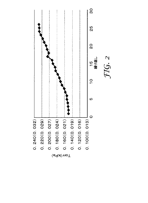
システムがパージされ、加熱器がそれらのそれぞれの設定点で安定した後、第1の反応性ガスを第1の反応性ガス供給タンクから放出した。第1の反応性ガスラインのニードル弁は、ガス流が、真空システムの影響を受けて、N2の等価流速である1〜25sccmと一致して、ディスクを通って出口まで流れるように調整された。第1の反応性ガスが3枚のディスクの表面を十分に飽和した後(前駆体の存在及び最後の膜を出て行く副生成物のガスの還元でRGAによって検出される)、第1の反応性ガスの流れは終了し、システムを10〜25sccmの流速でN2パージで再度フラッシングした。パージが完了した時点で、再び3枚のディスクが十分に飽和されるまで、第2の反応性ガスを同じような方法で(異なるポートであるが)第2の供給タンクから放出した。10〜25sccmの流速でN2パージによる別のフラッシングを行った。この添加サイクル(即ち、第1の反応性ガス−バージ−第2の反応性ガス−バージ)を継続し、ディスクは35回の繰り返しを受けた。 After the system was purged and the heaters stabilized at their respective set points, the first reactive gas was released from the first reactive gas supply tank. The needle valve of the first reactive gas line, the gas flow is affected by the vacuum system, consistent with an equivalent flow rate of N 2 1~25sccm, it is adjusted through the disc to flow to an outlet It was. After the first reactive gas sufficiently saturates the surfaces of the three disks (detected by RGA in the presence of precursors and reduction of byproduct gas exiting the last film), the first The reactive gas flow was terminated and the system was flushed again with a N 2 purge at a flow rate of 10-25 sccm. When the purge was complete, the second reactive gas was released from the second supply tank in a similar manner (although at a different port) until the three disks were fully saturated again. It was another flushing with N 2 purge at a flow rate of 10~25Sccm. This addition cycle (i.e., first reactive gas-barge-second reactive gas-barge) was continued and the disk was subjected to 35 iterations.
各繰り返しの完了時、乾燥窒素での最終パージの終わりに、ディスクの入口側と出口側との間で反応器内圧力差が観察された。このデータを記録して、一定のガス流速で膜全体に酸化アルミニウムを添加したことにより生じたデルタ圧を決定した。サイクルが進行するにつれて、プロセスガスに対する膜全体の検出可能な圧力の上昇が存在したことが判明した。このデルタ圧の上昇は、図2のグラフで示されている。 At the completion of each iteration, at the end of the final purge with dry nitrogen, an in-reactor pressure difference was observed between the inlet and outlet sides of the disk. This data was recorded to determine the delta pressure caused by the addition of aluminum oxide across the membrane at a constant gas flow rate. It was found that as the cycle progressed, there was a detectable increase in pressure across the membrane relative to the process gas. This increase in delta pressure is shown in the graph of FIG.
35回の繰り返しを行った後、反応器を開き、試料Aの3枚のディスクのそれぞれの表面エネルギーを評価した。各ディスクは86ダイン/cm(0.086N/m)を超える表面エネルギーを有し、高度の親水性を示すことが判明した。 After 35 repetitions, the reactor was opened and the surface energy of each of the three discs of Sample A was evaluated. Each disc was found to have a surface energy greater than 86 dynes / cm (0.086 N / m) and to exhibit a high degree of hydrophilicity.
(実施例2)
実験は、使用した基材が基材Aでなく基材Bであり、反応器、第1及び第2の入口ライン、及びパージガスラインを加熱器で60℃に加熱し、繰り返しの回数が35回でなく20回であったことを除いて、概ね実施例1の手順に従って実施された。20回の繰り返しを行った後、反応器を開き、試料Bの3枚のディスクのそれぞれの表面エネルギーを評価した。各ディスクは86ダイン/cm(0.086N/m)を超える表面エネルギーを有し、高度の親水性を示すことが判明した。
(Example 2)
In the experiment, the substrate used was not the substrate A but the substrate B, and the reactor, the first and second inlet lines, and the purge gas line were heated to 60 ° C. with a heater, and the number of repetitions was 35 times. The procedure was generally according to the procedure of Example 1, except that it was 20 times. After 20 repetitions, the reactor was opened and the surface energy of each of the three discs of Sample B was evaluated. Each disc was found to have a surface energy greater than 86 dynes / cm (0.086 N / m) and to exhibit a high degree of hydrophilicity.
(実施例3)
実験は、使用した基材が基材Aでなく基材Cであり、反応器、第1及び第2の入口ライン、及びパージガスラインを加熱器で60℃に加熱し、繰り返しの回数が35回でなく17回であったことを除いて、概ね実施例1の手順に従って実施された。17回の繰り返しを行った後、反応器を開き、試料Cの3枚のディスクのそれぞれの表面エネルギーを評価した。各ディスクは86ダイン/cm(0.086N/m)を超える表面エネルギーを有し、高度の親水性を示すことが判明した。
Example 3
In the experiment, the substrate used was not the substrate A but the substrate C, and the reactor, the first and second inlet lines, and the purge gas line were heated to 60 ° C. with a heater, and the number of repetitions was 35 times. The procedure was generally according to the procedure of Example 1, except that it was 17 times. After repeating 17 times, the reactor was opened, and the surface energy of each of the three discs of Sample C was evaluated. Each disc was found to have a surface energy greater than 86 dynes / cm (0.086 N / m) and to exhibit a high degree of hydrophilicity.
(実施例4)
実験は、使用した基材が基材Aでなく基材Dであり、反応器を加熱器で60℃に加熱し、第1及び第2の入口ライン及びパージガスラインを加熱器で70℃に加熱し、繰り返しの回数が35回でなく20回であったことを除いて、概ね実施例1の手順に従って実施された。20回の繰り返しを行った後、反応器を開いた基材がコーティングされたことを実証するためにX線分析を行った。
Example 4
In the experiment, the substrate used was not substrate A but substrate D, the reactor was heated to 60 ° C. with a heater, and the first and second inlet lines and the purge gas line were heated to 70 ° C. with a heater. The procedure was substantially the same as in Example 1 except that the number of repetitions was 20 instead of 35. After 20 iterations, X-ray analysis was performed to demonstrate that the substrate with the reactor open was coated.
(実施例5)
実験は、使用した基材が基材Aでなく基材Eであり、反応器を加熱器で60℃に加熱し、第1及び第2の入口ライン及びパージガスラインを加熱器で70℃に加熱し、繰り返しの回数が35回でなく20回であったことを除いて、概ね実施例1の手順に従って実施された。20回の繰り返しを行った後、反応器を開いた。基材がコーティングされたことを実証するためにX線分析を行った。
(Example 5)
In the experiment, the substrate used was not substrate A but substrate E, the reactor was heated to 60 ° C. with a heater, and the first and second inlet lines and the purge gas line were heated to 70 ° C. with a heater. The procedure was substantially the same as in Example 1 except that the number of repetitions was 20 instead of 35. After 20 repetitions, the reactor was opened. X-ray analysis was performed to demonstrate that the substrate was coated.
本明細書中に引用される刊行物の完全な開示は、それぞれが個々に組み込まれたかのように、その全体が参照により組み込まれる。本発明の範囲及び趣旨から逸脱しない本発明の様々な変更や改変は、当業者には明らかとなるであろう。本発明は、本明細書で述べる例示的な実施形態及び実施例によって不当に限定されるものではないこと、また、こうした実施例及び実施形態は、本明細書において以下に記述する「特許請求の範囲」によってのみ限定されると意図する本発明の範囲に関する例示のためにのみ提示されることを理解すべきである。
本発明はまた、以下の内容を包含する。
(1)
多孔性非セラミック基材上にコンフォーマルコーティングを堆積させる方法であって、
入口と出口とを有する反応器を提供する工程と、
多孔性非セラミック基材が前記入口を前記出口から分離するように、少なくとも1つの前記多孔性非セラミック基材の少なくとも一部を配置する工程と、
第1及び第2の反応性ガスを前記多孔性非セラミック基材を通して出口まで流して、前記多孔性非セラミック基材の内部表面における一連の2回以上の自己制限的な反応を行って、前記内部表面の少なくとも一部の上にコンフォーマルコーティングを形成するように、前記入口における前記第1及び第2の反応性ガスの順次導入の少なくとも1回の繰り返しを実施する工程と、を含む、方法。
(2)
前記実施工程が、少なくとも8回の繰り返しで行われる、項目1に記載の方法。
(3)
前記実施工程が、少なくとも20回の繰り返しで行われる、項目2に記載の方法。
(4)
前記実施工程が、前記内部表面の表面エネルギーが72ダイン/cmを超えるまで繰り返される、項目1に記載の方法。
(5)
前記出口に最も近い前記多孔性非セラミック基材の外部表面が、72ダイン/cm未満の表面エネルギーを有する、項目4に記載の方法。
(6)
前記多孔性非セラミック基材が多孔性ポリマー基材であり、前記導入が、前記多孔性ポリマー基材の融解温度を下回る温度で行われる、項目1に記載の方法。
(7)
第2の多孔性非セラミック基材もまた前記入口を前記出口から分離するように、少なくとも前記第2の多孔性非セラミック基材の少なくとも一部を配置することを更に含む、項目1に記載の方法。
(8)
前記多孔性非セラミック基材が、不定長の材料のウェブの形態であり、前記配置手段がロールツーロールプロセスを可能とするものである、項目1に記載の方法。
(9)
前記ロールツーロールプロセスが、ステップアンドリピートプロセスである、項目8に記載の方法。
(10)
前記ロールツーロールプロセスが、連続移動プロセスである、項目8に記載の方法。
(11)
前記反応器がフィルタ本体の形態である、項目1に記載の方法。
(12)
前記第1又は第2の反応性ガスの少なくとも一方が、非反応性搬送ガス成分を含む、項目10に記載の方法。
(13)
前記多孔性非セラミック基材が多孔性ポリマー基材である、項目1に記載の方法。
(14)
前記多孔性ポリマー基材がTIPS基材である、項目13に記載の方法。
(15)
前記多孔性ポリマー基材が不織布基材である、項目13に記載の方法。
(16)
前記コンフォーマルコーティングが、金属酸化物、金属窒化物、金属硫化物、又はこれらの組み合わせを含む、項目1に記載の方法。
(17)
前記金属が、ケイ素、チタン、アルミニウム、ジルコニウム、及びイットリウムからなる群から選択される、項目16に記載の方法。
(18)
前記金属が、ケイ素、チタン、及びアルミニウムからなる群から選択される、項目17に記載の方法。
(19)
前記金属がアルミニウムである、項目18に記載の方法。
(20)
前記コンフォーマルコーティングが酸化アルミニウムを含む、項目16に記載の方法。
(21)
前記第1及び第2の反応性ガスの前記導入の間の温度が、約300℃以下である、項目1に記載の方法。
(22)
前記第1及び第2の反応性ガスの前記導入の間の温度が、約60℃以下である、項目21に記載の方法。
(23)
前記コンフォーマルコーティングに化学部分をグラフティングする工程を更に含む、項目1に記載の方法。
(24)
コンフォーマルコーティングが、前記多孔性非セラミック基材の内部表面全体に形成される、項目1に記載の方法。
(25)
実施する繰り返しの回数を制御することにより、前記コンフォーマルコーティングを使用して前記多孔性非セラミック基材の気孔率を低減して所望の気孔率を達成する、項目1に記載の方法。
The complete disclosures of the publications cited herein are incorporated by reference in their entirety as if each were individually incorporated. Various changes and modifications of this invention will become apparent to those skilled in the art without departing from the scope and spirit of this invention. The present invention is not unduly limited by the exemplary embodiments and examples described herein, and such examples and embodiments are described below in the claims. It is to be understood that these are provided for illustration only with respect to the scope of the present invention which is intended to be limited only by the “range”.
The present invention also includes the following contents.
(1)
A method of depositing a conformal coating on a porous non-ceramic substrate comprising:
Providing a reactor having an inlet and an outlet;
Disposing at least a portion of at least one of the porous non-ceramic substrates such that a porous non-ceramic substrate separates the inlet from the outlet;
Flowing a first and second reactive gas through the porous non-ceramic substrate to an outlet to perform a series of two or more self-limiting reactions on the internal surface of the porous non-ceramic substrate; Performing at least one iteration of sequential introduction of the first and second reactive gases at the inlet to form a conformal coating on at least a portion of an interior surface. .
(2)
Item 2. The method according to Item 1, wherein the performing step is performed at least 8 times.
(3)
Item 3. The method according to Item 2, wherein the performing step is performed at least 20 times.
(4)
Item 2. The method of item 1, wherein the performing step is repeated until the surface energy of the inner surface exceeds 72 dynes / cm.
(5)
(6)
Item 2. The method according to Item 1, wherein the porous non-ceramic substrate is a porous polymer substrate, and the introduction is performed at a temperature below the melting temperature of the porous polymer substrate.
(7)
Item 2. The item 1, further comprising disposing at least a portion of at least the second porous non-ceramic substrate such that the second porous non-ceramic substrate also separates the inlet from the outlet. Method.
(8)
Item 2. The method of item 1, wherein the porous non-ceramic substrate is in the form of a web of indefinite length of material and the placement means enables a roll-to-roll process.
(9)
9. A method according to item 8, wherein the roll-to-roll process is a step and repeat process.
(10)
9. A method according to item 8, wherein the roll-to-roll process is a continuous movement process.
(11)
2. A method according to item 1, wherein the reactor is in the form of a filter body.
(12)
Item 11. The method of
(13)
Item 2. The method of item 1, wherein the porous non-ceramic substrate is a porous polymer substrate.
(14)
14. A method according to item 13, wherein the porous polymer substrate is a TIPS substrate.
(15)
Item 14. The method according to Item 13, wherein the porous polymer substrate is a nonwoven substrate.
(16)
The method of claim 1, wherein the conformal coating comprises a metal oxide, a metal nitride, a metal sulfide, or a combination thereof.
(17)
The method according to item 16, wherein the metal is selected from the group consisting of silicon, titanium, aluminum, zirconium, and yttrium.
(18)
18. A method according to item 17, wherein the metal is selected from the group consisting of silicon, titanium, and aluminum.
(19)
19. A method according to item 18, wherein the metal is aluminum.
(20)
The method of item 16, wherein the conformal coating comprises aluminum oxide.
(21)
The method of item 1, wherein the temperature during the introduction of the first and second reactive gases is about 300 ° C. or less.
(22)
22. The method of item 21, wherein the temperature during the introduction of the first and second reactive gases is about 60 ° C. or less.
(23)
The method of item 1, further comprising the step of grafting a chemical moiety on the conformal coating.
(24)
Item 2. The method of item 1, wherein a conformal coating is formed on the entire internal surface of the porous non-ceramic substrate.
(25)
The method of item 1, wherein the conformal coating is used to reduce the porosity of the porous non-ceramic substrate to achieve a desired porosity by controlling the number of repetitions performed.
Claims (4)
入口と出口とを有する反応器を提供する工程と、
多孔性疎水性ポリマー基材が前記入口を前記出口から分離するように、少なくとも1つの前記多孔性疎水性ポリマー基材の少なくとも一部を配置する工程と、
第1及び第2の反応性ガスを前記多孔性疎水性ポリマー基材を通して出口まで流して、前記多孔性疎水性ポリマー基材の内部表面における一連の2回以上の自己制限的な反応を行って、前記内部表面の少なくとも一部の上にコンフォーマルコーティングを形成するように、前記入口における前記第1及び第2の反応性ガスの順次導入の少なくとも1回の繰り返しを実施する工程と、を含み、
前記実施工程が、前記内部表面の表面エネルギーが72ダイン/cm(0.072N/m)を超えるまで繰り返される、
方法。 A method of depositing a conformal coating on a porous hydrophobic polymer substrate comprising:
Providing a reactor having an inlet and an outlet;
Disposing at least a portion of at least one of the porous hydrophobic polymer substrate such that the porous hydrophobic polymer substrate separates the inlet from the outlet;
First and second reactive gases are flowed through the porous hydrophobic polymer substrate to the outlet to perform a series of two or more self-limiting reactions on the inner surface of the porous hydrophobic polymer substrate. Performing at least one repetition of sequential introduction of the first and second reactive gases at the inlet to form a conformal coating on at least a portion of the interior surface. ,
The performing step is repeated until the surface energy of the internal surface exceeds 72 dynes / cm (0.072 N / m) ,
Method.
Applications Claiming Priority (5)
| Application Number | Priority Date | Filing Date | Title |
|---|---|---|---|
| US24469609P | 2009-09-22 | 2009-09-22 | |
| US24471309P | 2009-09-22 | 2009-09-22 | |
| US61/244,696 | 2009-09-22 | ||
| US61/244,713 | 2009-09-22 | ||
| PCT/US2010/048902 WO2011037798A1 (en) | 2009-09-22 | 2010-09-15 | Method of applying atomic layer deposition coatings onto porous non-ceramic substrates |
Publications (3)
| Publication Number | Publication Date |
|---|---|
| JP2013505368A JP2013505368A (en) | 2013-02-14 |
| JP2013505368A5 JP2013505368A5 (en) | 2013-10-03 |
| JP5681192B2 true JP5681192B2 (en) | 2015-03-04 |
Family
ID=43796159
Family Applications (2)
| Application Number | Title | Priority Date | Filing Date |
|---|---|---|---|
| JP2012530934A Expired - Fee Related JP5681192B2 (en) | 2009-09-22 | 2010-09-15 | Method for applying atomic layer deposition coatings on porous non-ceramic substrates |
| JP2012530946A Pending JP2013505156A (en) | 2009-09-22 | 2010-09-17 | Article comprising a porous substrate having a conformal layer on top |
Family Applications After (1)
| Application Number | Title | Priority Date | Filing Date |
|---|---|---|---|
| JP2012530946A Pending JP2013505156A (en) | 2009-09-22 | 2010-09-17 | Article comprising a porous substrate having a conformal layer on top |
Country Status (7)
| Country | Link |
|---|---|
| US (2) | US8859040B2 (en) |
| EP (2) | EP2480703A4 (en) |
| JP (2) | JP5681192B2 (en) |
| KR (2) | KR101714814B1 (en) |
| CN (2) | CN102575346B (en) |
| BR (2) | BR112012005212A2 (en) |
| WO (2) | WO2011037798A1 (en) |
Families Citing this family (49)
| Publication number | Priority date | Publication date | Assignee | Title |
|---|---|---|---|---|
| EP2460158A4 (en) | 2009-07-27 | 2013-09-04 | METHOD AND APPARATUS FOR PROCESSING AUDIO SIGNAL | |
| JP5681192B2 (en) * | 2009-09-22 | 2015-03-04 | スリーエム イノベイティブ プロパティズ カンパニー | Method for applying atomic layer deposition coatings on porous non-ceramic substrates |
| CN102770196A (en) * | 2009-11-11 | 2012-11-07 | 新纳米有限公司 | porous material |
| WO2012129143A1 (en) | 2011-03-24 | 2012-09-27 | 3M Innovative Properties Company | Dental adhesive comprising a coated polymeric component |
| CN103782153A (en) * | 2011-04-27 | 2014-05-07 | 俄亥俄州大学 | Methods and devices for the detection of biofilms |
| JP6231483B2 (en) * | 2011-10-31 | 2017-11-15 | スリーエム イノベイティブ プロパティズ カンパニー | Method for applying a coating to a roll-shaped substrate |
| WO2013138698A1 (en) | 2012-03-15 | 2013-09-19 | Massachusetts Institute Of Technology | Graphene based filter |
| CN103111549A (en) * | 2013-02-05 | 2013-05-22 | 苏州红荔汽车零部件有限公司 | Automatic production line of U-shaped connecting pipe fitting of automobile seat framework |
| WO2014121450A1 (en) * | 2013-02-05 | 2014-08-14 | Wang Dongjun | Roll-to-roll type atomic layer deposition equipment and method of use thereof |
| US11326255B2 (en) * | 2013-02-07 | 2022-05-10 | Uchicago Argonne, Llc | ALD reactor for coating porous substrates |
| JP2016532774A (en) | 2013-07-16 | 2016-10-20 | スリーエム イノベイティブ プロパティズ カンパニー | Film roll processing |
| US9598769B2 (en) | 2013-07-24 | 2017-03-21 | Uchicago Argonne, Llc | Method and system for continuous atomic layer deposition |
| EP3062914A4 (en) * | 2013-11-01 | 2017-07-05 | Massachusetts Institute of Technology | Mitigating leaks in membranes |
| US9902141B2 (en) | 2014-03-14 | 2018-02-27 | University Of Maryland | Layer-by-layer assembly of graphene oxide membranes via electrostatic interaction and eludication of water and solute transport mechanisms |
| CN107615462A (en) * | 2015-02-13 | 2018-01-19 | 恩特格里斯公司 | Coatings for enhancing the properties and performance of substrate articles and devices |
| US10201667B2 (en) | 2015-03-26 | 2019-02-12 | Becton, Dickinson And Company | IV membrane attachment systems and methods |
| US10702689B2 (en) | 2015-03-26 | 2020-07-07 | Becton, Dickinson And Company | Auto-stop vent plug |
| US10232130B2 (en) | 2015-03-26 | 2019-03-19 | Becton, Dickinson And Company | Anti-run dry membrane |
| US10646648B2 (en) | 2015-04-01 | 2020-05-12 | Becton, Dickinson And Company | IV flow management systems and methods |
| ES2759992T3 (en) | 2015-07-07 | 2020-05-12 | I3 Membrane Gmbh | Procedure for electrosorption and electrofiltration using a metal-coated polymer membrane, and procedure therefor |
| US10124299B2 (en) * | 2015-09-08 | 2018-11-13 | Gwangju Institute Of Science And Technology | Membrane based on graphene and method of manufacturing same |
| US10550010B2 (en) | 2015-12-11 | 2020-02-04 | Uchicago Argonne, Llc | Oleophilic foams for oil spill mitigation |
| US10974208B2 (en) | 2016-05-11 | 2021-04-13 | Massachusetts Institute Of Technology | Graphene oxide membranes and related methods |
| WO2018009882A1 (en) | 2016-07-08 | 2018-01-11 | Uchicago Argonne, Llc | Functionalized foams |
| KR102218855B1 (en) * | 2017-07-12 | 2021-02-23 | 주식회사 엘지화학 | Apparatus and method for coating surface of porous substrate |
| US11896935B2 (en) | 2017-08-17 | 2024-02-13 | Uchicago Argonne, Llc | Filtration membranes |
| US12012559B2 (en) | 2018-05-11 | 2024-06-18 | Uchicago Argonne, Llc | Janus membranes via atomic layer deposition |
| US11590456B2 (en) * | 2018-05-31 | 2023-02-28 | Uchicago Argonne, Llc | Systems and methods for oleophobic composite membranes |
| US12083483B2 (en) | 2018-06-28 | 2024-09-10 | Massachusetts Institute Of Technology | Coatings to improve the selectivity of atomically thin membranes |
| US11351478B2 (en) | 2018-09-06 | 2022-06-07 | Uchicago Argonne, Llc | Oil skimmer with oleophilic coating |
| US11548798B2 (en) | 2019-04-23 | 2023-01-10 | Uchicago Argonne, Llc | Compressible foam electrode |
| KR102745250B1 (en) * | 2019-04-29 | 2024-12-23 | 주식회사 엘지에너지솔루션 | Apparatus of Atomic Layer Deposition |
| EP3969158A1 (en) | 2019-05-15 | 2022-03-23 | Via Separations, Inc. | Filtration apparatus containing graphene oxide membrane |
| EP3969157A1 (en) | 2019-05-15 | 2022-03-23 | Via Separations, Inc. | Durable graphene oxide membranes |
| KR20200141002A (en) * | 2019-06-06 | 2020-12-17 | 에이에스엠 아이피 홀딩 비.브이. | Method of using a gas-phase reactor system including analyzing exhausted gas |
| US11117346B2 (en) * | 2019-07-18 | 2021-09-14 | Hamilton Sundstrand Corporation | Thermally-conductive polymer and components |
| US11111578B1 (en) | 2020-02-13 | 2021-09-07 | Uchicago Argonne, Llc | Atomic layer deposition of fluoride thin films |
| JP2021130227A (en) * | 2020-02-19 | 2021-09-09 | 株式会社リコー | Filters and their manufacturing methods, water purification equipment, power generation equipment, and power generation systems |
| US12042764B2 (en) * | 2020-05-11 | 2024-07-23 | Hamilton Sundstrand Corporation | Aircraft air management systems for deactivating contaminants |
| FR3112796B1 (en) | 2020-07-21 | 2022-11-25 | Inst Polytechnique Grenoble | Process for functionalizing a substrate based on a polymer by chemical deposition of a thin layer |
| US12154698B2 (en) * | 2020-08-05 | 2024-11-26 | Uchicago Argonne, Llc | Coated fuel pellets, methods of making and using same |
| JP7608267B2 (en) | 2021-05-19 | 2025-01-06 | 日本航空電子工業株式会社 | Multi-band Antennas |
| JP7591972B2 (en) | 2021-05-19 | 2024-11-29 | 日本航空電子工業株式会社 | Multi-band Antennas |
| US12065738B2 (en) | 2021-10-22 | 2024-08-20 | Uchicago Argonne, Llc | Method of making thin films of sodium fluorides and their derivatives by ALD |
| WO2023097166A1 (en) | 2021-11-29 | 2023-06-01 | Via Separations, Inc. | Heat exchanger integration with membrane system for evaporator pre-concentration |
| WO2023141227A1 (en) * | 2022-01-19 | 2023-07-27 | Ken Gen Energy, Llc | Pulse energy generator system |
| US11901169B2 (en) | 2022-02-14 | 2024-02-13 | Uchicago Argonne, Llc | Barrier coatings |
| DE102022106876A1 (en) | 2022-03-23 | 2023-09-28 | Technische Universität Dresden, Körperschaft des öffentlichen Rechts | Filter structure as well as its production and use |
| CN116695091B (en) * | 2023-08-01 | 2023-09-29 | 南京原磊纳米材料有限公司 | Hydrophobic conductive film and preparation method and application thereof |
Family Cites Families (38)
| Publication number | Priority date | Publication date | Assignee | Title |
|---|---|---|---|---|
| DE3300095A1 (en) * | 1982-01-06 | 1983-07-28 | Sando Iron Works Co., Ltd., Wakayama | Installation for the continuous treatment of textile products with the aid of low-temperature plasma |
| US4726989A (en) | 1986-12-11 | 1988-02-23 | Minnesota Mining And Manufacturing | Microporous materials incorporating a nucleating agent and methods for making same |
| US5120594A (en) | 1989-11-20 | 1992-06-09 | Minnesota Mining And Manufacturing Company | Microporous polyolefin shaped articles with patterned surface areas of different porosity |
| ATE208700T1 (en) * | 1994-07-22 | 2001-11-15 | Fraunhofer Ges Forschung | METHOD AND DEVICE FOR PLASMA MODIFICATION OF FLAT POROUS OBJECTS |
| JP3682465B2 (en) * | 1999-03-31 | 2005-08-10 | 独立行政法人産業技術総合研究所 | Resin molded product surface layer modification method and apparatus therefor, and resin molded product with modified surface layer, resin molded product surface layer colored method and apparatus and surface molded resin product with colored surface layer, and Resin molded product with added functionality by modifying the surface layer |
| US6613383B1 (en) | 1999-06-21 | 2003-09-02 | Regents Of The University Of Colorado | Atomic layer controlled deposition on particle surfaces |
| JP2001279453A (en) * | 2000-03-29 | 2001-10-10 | Japan Vilene Co Ltd | Discharge treatment apparatus for porous body and discharge treatment method for porous body |
| US6713177B2 (en) | 2000-06-21 | 2004-03-30 | Regents Of The University Of Colorado | Insulating and functionalizing fine metal-containing particles with conformal ultra-thin films |
| FR2818291B1 (en) * | 2000-12-19 | 2003-11-07 | Snecma Moteurs | DENSIFICATION OF HOLLOW POROUS SUBSTRATES BY CHEMICAL STEAM INFILTRATION |
| US9376750B2 (en) * | 2001-07-18 | 2016-06-28 | Regents Of The University Of Colorado, A Body Corporate | Method of depositing an inorganic film on an organic polymer |
| US6878419B2 (en) * | 2001-12-14 | 2005-04-12 | 3M Innovative Properties Co. | Plasma treatment of porous materials |
| US7157117B2 (en) * | 2002-06-26 | 2007-01-02 | Sigma Laboratories Of Arizona, Llc | Functionalization of porous materials by vacuum deposition of polymers |
| US20040089237A1 (en) * | 2002-07-17 | 2004-05-13 | Pruett James Gary | Continuous chemical vapor deposition process and process furnace |
| US8304019B1 (en) * | 2004-02-19 | 2012-11-06 | Nanosolar Inc. | Roll-to-roll atomic layer deposition method and system |
| US7045205B1 (en) * | 2004-02-19 | 2006-05-16 | Nanosolar, Inc. | Device based on coated nanoporous structure |
| US20060234210A1 (en) | 2004-04-14 | 2006-10-19 | Affinergy, Inc. | Filtration device and method for removing selected materials from biological fluids |
| JP4534565B2 (en) * | 2004-04-16 | 2010-09-01 | 株式会社デンソー | Method for producing ceramic porous |
| FI117247B (en) | 2004-06-24 | 2006-08-15 | Beneq Oy | Selective alloying of material |
| JP5307536B2 (en) * | 2005-05-25 | 2013-10-02 | ゴア エンタープライズ ホールディングス,インコーポレイティド | Multifunctional coating on microporous substrate |
| EP1937884B1 (en) | 2005-10-11 | 2014-01-01 | NV Bekaert SA | Coated porous metal medium |
| BRPI0620837A2 (en) * | 2005-12-30 | 2011-11-29 | 3M Innovative Properties Co | method of manufacturing functionalized substrates |
| KR20080092983A (en) | 2006-02-07 | 2008-10-16 | 프레지던트 앤드 펠로우즈 오브 하바드 칼리지 | Vaporization Functionalization of Carbon Nanotubes |
| US20070272606A1 (en) * | 2006-05-25 | 2007-11-29 | Freese Donald T | Multi-functional coatings on microporous substrates |
| US20070281089A1 (en) * | 2006-06-05 | 2007-12-06 | General Electric Company | Systems and methods for roll-to-roll atomic layer deposition on continuously fed objects |
| EP1884578A1 (en) | 2006-07-31 | 2008-02-06 | MPG Max-Planck-Gesellschaft zur Förderung der Wissenschaften e.V. | A method of manufacturing a self-ordered porous structure of aluminium oxide, a nanoporous article and a nano object |
| US20080119098A1 (en) * | 2006-11-21 | 2008-05-22 | Igor Palley | Atomic layer deposition on fibrous materials |
| JP5412294B2 (en) | 2007-02-14 | 2014-02-12 | 本田技研工業株式会社 | Fabrication method of spatially dispersed nanostructures controlled in size by atomic layer deposition |
| US7842214B2 (en) | 2007-03-28 | 2010-11-30 | 3M Innovative Properties Company | Process for forming microporous membranes |
| JP5060224B2 (en) | 2007-09-12 | 2012-10-31 | 株式会社東芝 | Signal processing apparatus and method |
| US20090081356A1 (en) * | 2007-09-26 | 2009-03-26 | Fedorovskaya Elena A | Process for forming thin film encapsulation layers |
| WO2009070574A2 (en) | 2007-11-27 | 2009-06-04 | North Carolina State University | Methods for modification of polymers, fibers and textile media |
| US9564629B2 (en) * | 2008-01-02 | 2017-02-07 | Nanotek Instruments, Inc. | Hybrid nano-filament anode compositions for lithium ion batteries |
| AU2009207824B2 (en) * | 2008-01-24 | 2013-11-21 | Société des Produits Nestlé S.A. | Capsule with integrated antimicrobial filter |
| US9279120B2 (en) * | 2008-05-14 | 2016-03-08 | The Regents Of The University Of Colorado, A Body Corporate | Implantable devices having ceramic coating applied via an atomic layer deposition method |
| BRPI0913710A2 (en) | 2008-09-19 | 2015-10-13 | 3M Innovative Properties Co | "article and methods for article preparation" |
| WO2010120531A2 (en) | 2009-04-01 | 2010-10-21 | Cornell University | Conformal particle coatings on fiber materials for use in spectroscopic methods for detecting targets of interest and methods based thereon |
| WO2011035195A1 (en) | 2009-09-18 | 2011-03-24 | Nano Terra Inc. | Functional nanofibers and methods of making and using the same |
| JP5681192B2 (en) * | 2009-09-22 | 2015-03-04 | スリーエム イノベイティブ プロパティズ カンパニー | Method for applying atomic layer deposition coatings on porous non-ceramic substrates |
-
2010
- 2010-09-15 JP JP2012530934A patent/JP5681192B2/en not_active Expired - Fee Related
- 2010-09-15 CN CN201080042180.XA patent/CN102575346B/en not_active Expired - Fee Related
- 2010-09-15 EP EP10819262.6A patent/EP2480703A4/en not_active Withdrawn
- 2010-09-15 KR KR1020127010021A patent/KR101714814B1/en not_active Expired - Fee Related
- 2010-09-15 US US13/392,213 patent/US8859040B2/en not_active Expired - Fee Related
- 2010-09-15 WO PCT/US2010/048902 patent/WO2011037798A1/en not_active Ceased
- 2010-09-15 BR BR112012005212A patent/BR112012005212A2/en not_active IP Right Cessation
- 2010-09-17 WO PCT/US2010/049250 patent/WO2011037831A2/en not_active Ceased
- 2010-09-17 CN CN201080042237.6A patent/CN102782179B/en not_active Expired - Fee Related
- 2010-09-17 EP EP10819281.6A patent/EP2480702A4/en not_active Withdrawn
- 2010-09-17 JP JP2012530946A patent/JP2013505156A/en active Pending
- 2010-09-17 KR KR1020127010019A patent/KR101720821B1/en not_active Expired - Fee Related
- 2010-09-17 US US13/390,900 patent/US20120171403A1/en not_active Abandoned
- 2010-09-17 BR BR112012005997A patent/BR112012005997A2/en not_active IP Right Cessation
Also Published As
| Publication number | Publication date |
|---|---|
| EP2480702A4 (en) | 2013-10-30 |
| BR112012005997A2 (en) | 2016-03-22 |
| EP2480702A2 (en) | 2012-08-01 |
| JP2013505368A (en) | 2013-02-14 |
| WO2011037798A1 (en) | 2011-03-31 |
| BR112012005212A2 (en) | 2016-03-15 |
| KR101714814B1 (en) | 2017-03-09 |
| WO2011037831A2 (en) | 2011-03-31 |
| US20120171376A1 (en) | 2012-07-05 |
| EP2480703A4 (en) | 2013-10-30 |
| CN102575346B (en) | 2015-01-28 |
| KR101720821B1 (en) | 2017-03-28 |
| CN102782179A (en) | 2012-11-14 |
| US8859040B2 (en) | 2014-10-14 |
| KR20120073280A (en) | 2012-07-04 |
| KR20120085262A (en) | 2012-07-31 |
| JP2013505156A (en) | 2013-02-14 |
| EP2480703A1 (en) | 2012-08-01 |
| WO2011037831A3 (en) | 2011-06-23 |
| US20120171403A1 (en) | 2012-07-05 |
| CN102782179B (en) | 2015-11-25 |
| CN102575346A (en) | 2012-07-11 |
Similar Documents
| Publication | Publication Date | Title |
|---|---|---|
| JP5681192B2 (en) | Method for applying atomic layer deposition coatings on porous non-ceramic substrates | |
| Zhang et al. | A simple and scalable method for preparing low-defect ZIF-8 tubular membranes | |
| Spagnola et al. | Surface and sub-surface reactions during low temperature aluminium oxide atomic layer deposition on fiber-forming polymers | |
| US20190168173A1 (en) | Nanocomposite membranes and methods of forming the same | |
| Weber et al. | Atomic layer deposition (ALD) on inorganic or polymeric membranes | |
| US7438193B2 (en) | Nanoporous membrane and method of fabricating the same | |
| CN104040022B (en) | Methods for applying a coating to a substrate in rolled form | |
| AU2011264922B2 (en) | Low-temperature synthesis of silica | |
| Yu et al. | A novel method for fabrication of high-flux zeolite membranes on supports with arbitrary geometry | |
| CN118001940B (en) | A reverse osmosis membrane and a method for preparing the reverse osmosis membrane. | |
| JP2017170435A (en) | Separation membrane and separation method | |
| Tran et al. | Plasma-enhanced atomic layer deposition of titania on alumina for its potential use as a hydrogen-selective membrane | |
| NL2016222B1 (en) | Preparation of inorganic tight nanofiltration membranes. | |
| TWI882219B (en) | Method for purifying iodosilanes | |
| Chang | Metal-organic framework thin film synthesis via a microfluidic pen system | |
| CN121240913A (en) | Atomic layer deposition of filter media | |
| Nijboer | Microporous ceramic nanofiltration membranes using atmospheric pressure atomic-and molecular layer deposition | |
| JP2008119566A (en) | Gas separator | |
| Karman et al. | 3D structuration of MOF layers for gas sensors enhancement and its application in microreactors | |
| Suraj et al. | Microporous Silica Membrane Prepared using TMOS/O~ 3 CVD in Opposing Reactants Geometry | |
| Ravindranath | Synthesis of boron nitride/vycor composite membrane structures by an optimized LPCVD process | |
| Nakao | Development of thermo-and steam-stable silica membranes for hydrogen permselective membrane reactor | |
| JP2008119565A (en) | Filter member and method of manufacturing filter member |
Legal Events
| Date | Code | Title | Description |
|---|---|---|---|
| A521 | Request for written amendment filed |
Free format text: JAPANESE INTERMEDIATE CODE: A523 Effective date: 20130816 |
|
| A621 | Written request for application examination |
Free format text: JAPANESE INTERMEDIATE CODE: A621 Effective date: 20130816 |
|
| A977 | Report on retrieval |
Free format text: JAPANESE INTERMEDIATE CODE: A971007 Effective date: 20140131 |
|
| A131 | Notification of reasons for refusal |
Free format text: JAPANESE INTERMEDIATE CODE: A131 Effective date: 20140204 |
|
| A521 | Request for written amendment filed |
Free format text: JAPANESE INTERMEDIATE CODE: A523 Effective date: 20140502 |
|
| A131 | Notification of reasons for refusal |
Free format text: JAPANESE INTERMEDIATE CODE: A131 Effective date: 20140812 |
|
| A521 | Request for written amendment filed |
Free format text: JAPANESE INTERMEDIATE CODE: A523 Effective date: 20140919 |
|
| TRDD | Decision of grant or rejection written | ||
| A01 | Written decision to grant a patent or to grant a registration (utility model) |
Free format text: JAPANESE INTERMEDIATE CODE: A01 Effective date: 20141209 |
|
| A61 | First payment of annual fees (during grant procedure) |
Free format text: JAPANESE INTERMEDIATE CODE: A61 Effective date: 20150108 |
|
| R150 | Certificate of patent or registration of utility model |
Ref document number: 5681192 Country of ref document: JP Free format text: JAPANESE INTERMEDIATE CODE: R150 |
|
| R250 | Receipt of annual fees |
Free format text: JAPANESE INTERMEDIATE CODE: R250 |
|
| R250 | Receipt of annual fees |
Free format text: JAPANESE INTERMEDIATE CODE: R250 |
|
| R250 | Receipt of annual fees |
Free format text: JAPANESE INTERMEDIATE CODE: R250 |
|
| LAPS | Cancellation because of no payment of annual fees |