JP5673495B2 - Wiring module - Google Patents
Wiring module Download PDFInfo
- Publication number
- JP5673495B2 JP5673495B2 JP2011240190A JP2011240190A JP5673495B2 JP 5673495 B2 JP5673495 B2 JP 5673495B2 JP 2011240190 A JP2011240190 A JP 2011240190A JP 2011240190 A JP2011240190 A JP 2011240190A JP 5673495 B2 JP5673495 B2 JP 5673495B2
- Authority
- JP
- Japan
- Prior art keywords
- connection
- cell group
- end side
- projection piece
- unit cell
- Prior art date
- Legal status (The legal status is an assumption and is not a legal conclusion. Google has not performed a legal analysis and makes no representation as to the accuracy of the status listed.)
- Expired - Fee Related
Links
Images


Classifications
-
- Y—GENERAL TAGGING OF NEW TECHNOLOGICAL DEVELOPMENTS; GENERAL TAGGING OF CROSS-SECTIONAL TECHNOLOGIES SPANNING OVER SEVERAL SECTIONS OF THE IPC; TECHNICAL SUBJECTS COVERED BY FORMER USPC CROSS-REFERENCE ART COLLECTIONS [XRACs] AND DIGESTS
- Y02—TECHNOLOGIES OR APPLICATIONS FOR MITIGATION OR ADAPTATION AGAINST CLIMATE CHANGE
- Y02E—REDUCTION OF GREENHOUSE GAS [GHG] EMISSIONS, RELATED TO ENERGY GENERATION, TRANSMISSION OR DISTRIBUTION
- Y02E60/00—Enabling technologies; Technologies with a potential or indirect contribution to GHG emissions mitigation
- Y02E60/10—Energy storage using batteries
Landscapes
- Connection Of Batteries Or Terminals (AREA)
Description
本発明は、配線モジュールに関する。 The present invention relates to a wiring module.
電気自動車やハイブリッド車用の電池モジュールは、正極及び負極の電極端子を有する単電池が複数個並んで配列されており、隣り合う単電池の電極端子間がバスバー(接続部材)で接続されることにより複数の単電池が直列や並列に接続されるようになっている。 In battery modules for electric vehicles and hybrid vehicles, a plurality of single cells having positive and negative electrode terminals are arranged side by side, and electrode terminals of adjacent single cells are connected by a bus bar (connection member). Thus, a plurality of single cells are connected in series or in parallel.
ここで、下記特許文献1のように、合成樹脂製の複数の単位ユニットにそれぞれ接続部材を収容し、隣り合う単位ユニットを連結することにより、複数の接続部材を一体的に装着することが考えられた。 Here, as in Patent Document 1 below, it is considered that a plurality of connecting members are integrally mounted by accommodating connecting members in a plurality of unit units made of synthetic resin, and connecting adjacent unit units. It was.
この特許文献1の電池接続アセンブリは、各単位ユニットの並び方向の一方の端部に、円柱状の延出部が並び方向に突出した係合部が設けられるとともに、並び方向の他方の端部に隣り合う単位ユニットの係合部と係合する被係合部が設けられている。この係合部には、延出部の先端に張出部が設けられており、被係合部には、延出部が嵌め込まれる挿通凹部が設けられている。 In the battery connection assembly of Patent Document 1, an engagement portion in which a columnar extending portion protrudes in the arrangement direction is provided at one end portion in the arrangement direction of the unit units, and the other end portion in the arrangement direction. An engaged portion that engages with an engaging portion of a unit unit adjacent to the unit unit is provided. The engaging portion is provided with a protruding portion at the tip of the extending portion, and the engaged portion is provided with an insertion concave portion into which the extending portion is fitted.
そして、このような複数の単位ユニット(連結部材)が係合部と被係合部とによって互いに連結されて電池接続アセンブリが構成されるようになっている。また、電池接続アセンブリを複数並んで配列された単電池群に装着することで、複数の単電池が直列や並列に接続される。 A plurality of such unit units (connecting members) are connected to each other by the engaging portion and the engaged portion to form a battery connection assembly. Moreover, a plurality of unit cells are connected in series or in parallel by attaching a plurality of cell connection assemblies to the unit cell group arranged side by side.
ここで、この電池接続アセンブリ(配線モジュール)は、係合部の円柱部分と挿通凹部により隣り合う単位ユニット(連結部材)間において並び方向への相対的な変位が許容されており、隣り合う複数の単電池の電極端子間に寸法公差がある場合であっても、単位ユニット(連結部材)間が相対的に移動することで、電極端子間の寸法公差に対応できるようになっている。 Here, in the battery connection assembly (wiring module), relative displacement in the alignment direction is allowed between the adjacent unit units (connecting members) by the cylindrical portion of the engaging portion and the insertion recess, and a plurality of adjacent battery units are connected. Even when there is a dimensional tolerance between the electrode terminals of the single cell, the dimensional tolerance between the electrode terminals can be accommodated by the relative movement between the unit units (connecting members).
ところで、配線モジュールを単電池に装着する際には、複数の単電池間の寸法公差のために、一般に、全ての連結部材を一体的に単電池群に組み付けることはせず、並び方向の一方の端部の連結部材から他方の端部側の連結部材へと順番に組み付けていく方が効率的である。 By the way, when mounting a wiring module to a unit cell, due to dimensional tolerances between a plurality of unit cells, in general, all connecting members are not integrally assembled into a unit cell group. It is more efficient to assemble in order from the connecting member on the other end to the connecting member on the other end.
ここで、この組み付けの際に、連結部材が並び方向に一直線状に連結されていると、単電池間の寸法公差に対応させることが難しいため、単電池群への組み付け作業性の観点から望ましくない。一方、並んで配列された連結部材を単電池群への組み付け方向とは反対側に撓ませることができれば、並び方向の一方の端部側の連結部材から並び方向の他方の端部側の連結部材へと順番に組み付けていくことが可能となり、配線モジュールの組み付け作業性を向上させることができる。 Here, if the connecting members are connected in a straight line in the arrangement direction at the time of this assembly, it is difficult to correspond to the dimensional tolerance between the single cells, which is desirable from the viewpoint of the workability of the assembly to the single cell group. Absent. On the other hand, if the connecting members arranged side by side can be bent in the direction opposite to the assembly direction to the unit cell group, the connecting member on one end side in the arranging direction can be connected on the other end side in the arranging direction. It becomes possible to assemble to a member in order, and the assembling workability of the wiring module can be improved.
しかしながら、特許文献1の構成では、隣り合う連結部材について、延出部の外周を挿通凹部に(ほとんど隙間なく)嵌め込んで連結する構成であるため、配線モジュール(複数並んで配列された連結部材)を単電池群への組み付け方向とは反対側に撓ませることが容易ではなく、配線モジュールの組み付け作業性が低下しやすいという問題があった。 However, in the configuration of Patent Document 1, since the adjacent connecting members are connected by fitting the outer periphery of the extended portion into the insertion recess (with almost no gap), a wiring module (a plurality of connecting members arranged side by side) ) Is not easy to bend in the direction opposite to the assembly direction to the unit cell group, and there is a problem that the workability of assembling the wiring module is likely to deteriorate.
本発明は上記のような事情に基づいて完成されたものであって、単電池群への組み付け作業性を向上させることが可能な配線モジュールを提供することを目的とする。 This invention is completed based on the above situations, Comprising: It aims at providing the wiring module which can improve the assembly workability | operativity to a cell group.
本発明に係る配線モジュールは、正極及び負極の電極端子を有する複数の単電池からなる単電池群に組み付けられる配線モジュールであって、前記複数の単電池に電気的に接続される複数の電線が配策される樹脂プロテクタを備え、前記樹脂プロテクタは、複数の連結部材が連結されて構成されるものであり、前記各連結部材は、当該連結部材における並び方向の一端側に設けられて前記並び方向に突出する連結突片と、前記連結部材における並び方向の他端側に設けられて隣り合う前記連結部材の前記連結突片が挿通される連結挿通部とを備えており、前記連結突片は、前記連結挿通部に挿通された状態で、前記単電池群への組み付け方向における前記連結挿通部との間に所定のクリアランスを形成する切欠部を有し、前記切欠部は、前記連結突片の上下方向の寸法を先端側に向かう程短くなるように下端側を切り欠き、前記連結突片の上端側は、前記切欠部を設けないようにするとともに、前記連結挿通部は、前記連結突片の上側に配される上壁と、前記連結突片の下側に配される係合壁とを備え、前記所定のクリアランスは、前記連結突片と前記係合壁との間に形成され、前記所定のクリアランスにより前記樹脂プロテクタにおける前記単電池群への組み付け方向とは反対側への撓み変形が許容されており、前記連結突片は、前記単電池群への組み付け方向の寸法が前記組み付け方向と直交する方向の寸法よりも大きい。 The wiring module according to the present invention is a wiring module that is assembled to a unit cell group including a plurality of unit cells having positive and negative electrode terminals, and a plurality of electric wires that are electrically connected to the plurality of unit cells. The resin protector includes a plurality of connecting members, and each of the connecting members is provided on one end side in the arranging direction of the connecting members. A connecting protrusion that protrudes in the direction, and a connecting insertion portion that is provided on the other end side in the alignment direction of the connecting member and through which the connecting protrusion of the adjacent connecting member is inserted. in a state where the inserted into the coupling insertion portion has a cutout portion for forming a predetermined clearance between said coupling insertion portion in the mounting direction of the cell group, wherein the notch, the The lower end side is cut out so that the vertical dimension of the connecting protrusion piece becomes shorter toward the tip end side, the upper end side of the connecting protrusion piece is not provided with the notch portion, and the connecting insertion part is An upper wall disposed on the upper side of the connection projecting piece; and an engagement wall disposed on the lower side of the connection projecting piece, wherein the predetermined clearance is between the connection projecting piece and the engagement wall. The resin protector is allowed to bend and deform in the direction opposite to the assembly direction to the unit cell group by the predetermined clearance , and the connecting projecting piece is in the assembly direction to the unit cell group. The dimension is larger than the dimension in the direction perpendicular to the assembly direction.
本構成によれば、所定のクリアランスにより樹脂プロテクタにおける単電池群への組み付け方向とは反対側への撓み変形が許容されるため、単電池群に対して連結部材の並び方向の一方の側から他方の側へと順番に組み付けていく作業が容易になる。よって、配線モジュールの単電池群への組み付け作業性を向上させることが可能となる。
なお、樹脂プロテクタにおける単電池群への組み付け方向については、切欠部を設けないことで所定のクリアランスを形成しないようにすれば、樹脂プロテクタにおける単電池群への組み付け方向の撓み変形を規制することができる。よって、例えば、単電池群への組み付けの前に樹脂プロテクタを持ち上げた際における組み付け方向の撓み変形を規制できるため、配線モジュールの組み付け位置への移動の際の作業性の低下を抑制できる。
また、組み付け方向や組み付け方向とは反対方向への力に対する連結突片の剛性を高めることができる。
本発明に係る配線モジュールは、正極及び負極の電極端子を有する複数の単電池からなる単電池群に組み付けられる配線モジュールであって、前記複数の単電池に電気的に接続される複数の電線が配策される樹脂プロテクタを備え、前記樹脂プロテクタは、複数の連結部材が連結されて構成されるものであり、前記各連結部材は、当該連結部材における並び方向の一端側に設けられて前記並び方向に突出する連結突片と、前記連結部材における並び方向の他端側に設けられて隣り合う前記連結部材の前記連結突片が挿通される連結挿通部とを備えており、前記連結突片は、前記連結挿通部に挿通された状態で、前記単電池群への組み付け方向における前記連結挿通部との間に所定のクリアランスを形成する切欠部を有し、前記切欠部は、前記連結突片の上下方向の寸法を先端側に向かう程短くなるように下端側を切り欠き、前記連結突片の上端側は、前記切欠部を設けないようにするとともに、前記連結挿通部は、前記連結突片の上側に配される上壁と、前記連結突片の下側に配される係合壁とを備え、前記所定のクリアランスは、前記連結突片と前記係合壁との間に形成され、前記所定のクリアランスにより前記樹脂プロテクタにおける前記単電池群への組み付け方向とは反対側への撓み変形が許容されており、前記各連結部材には、前記連結突片に沿って突出するガイド突片と、隣り合う前記連結部材の前記ガイド突片が挿通されるガイド受け部とを備えており、前記隣り合う連結部材の連結の際には、前記連結突片の先端部が前記連結挿通部に挿通されるよりも先に、前記ガイド突片の先端部が前記ガイド受け部に挿通される。
本構成によれば、所定のクリアランスにより樹脂プロテクタにおける単電池群への組み付け方向とは反対側への撓み変形が許容されるため、単電池群に対して連結部材の並び方向の一方の側から他方の側へと順番に組み付けていく作業が容易になる。よって、配線モジュールの単電池群への組み付け作業性を向上させることが可能となる。
なお、樹脂プロテクタにおける単電池群への組み付け方向については、切欠部を設けないことで所定のクリアランスを形成しないようにすれば、樹脂プロテクタにおける単電池群への組み付け方向の撓み変形を規制することができる。よって、例えば、単電池群への組み付けの前に樹脂プロテクタを持ち上げた際における組み付け方向の撓み変形を規制できるため、配線モジュールの組み付け位置への移動の際の作業性の低下を抑制できる。
また、隣り合う連結部材の連結の際に、連結突片の先端部が連結挿通部に挿通されるよりも先に、ガイド突片の先端部がガイド受け部に挿通されるため、ガイド突片を目安に連結部材を連結することが可能になる。よって、連結部材の連結の際の作業性を向上させることが可能になる。
本発明に係る配線モジュールは、正極及び負極の電極端子を有する複数の単電池からなる単電池群に組み付けられる配線モジュールであって、前記複数の単電池に電気的に接続される複数の電線が配策される樹脂プロテクタを備え、前記樹脂プロテクタは、複数の連結部材が連結されて構成されるものであり、前記各連結部材は、当該連結部材における並び方向の一端側に設けられて前記並び方向に突出する連結突片と、前記連結部材における並び方向の他端側に設けられて隣り合う前記連結部材の前記連結突片が挿通される連結挿通部とを備えており、前記連結突片は、前記連結挿通部に挿通された状態で、前記単電池群への組み付け方向における前記連結挿通部との間に所定のクリアランスを形成する切欠部を有し、前記切欠部は、前記連結突片の上下方向の寸法を先端側に向かう程短くなるように下端側を切り欠き、前記連結突片の上端側は、前記切欠部を設けないようにするとともに、前記連結挿通部は、前記連結突片の上側に配される上壁と、前記連結突片の下側に配される係合壁とを備え、前記所定のクリアランスは、前記連結突片と前記係合壁との間に形成され、前記所定のクリアランスにより前記樹脂プロテクタにおける前記単電池群への組み付け方向とは反対側への撓み変形が許容されており、前記各連結部材は、前記電極端子間を接続する接続部材を保持する保持部と、前記保持部に被せられるカバー部とを備えており、前記カバー部には、前記連結部材の並び方向に向けて突出するカバー係合部と、隣り合う連結部材の前記カバー係合部と係合するカバー被係合部とを有し、前記カバー係合部の突出方向は、前記カバー部を開いた状態において前記単電池群への組み付け方向とは反対側に傾斜している。
本構成によれば、所定のクリアランスにより樹脂プロテクタにおける単電池群への組み付け方向とは反対側への撓み変形が許容されるため、単電池群に対して連結部材の並び方向の一方の側から他方の側へと順番に組み付けていく作業が容易になる。よって、配線モジュールの単電池群への組み付け作業性を向上させることが可能となる。
なお、樹脂プロテクタにおける単電池群への組み付け方向については、切欠部を設けないことで所定のクリアランスを形成しないようにすれば、樹脂プロテクタにおける単電池群への組み付け方向の撓み変形を規制することができる。よって、例えば、単電池群への組み付けの前に樹脂プロテクタを持ち上げた際における組み付け方向の撓み変形を規制できるため、配線モジュールの組み付け位置への移動の際の作業性の低下を抑制できる。
また、樹脂プロテクタを撓ませた際に、カバー係合部とカバー被係合部との係合が解除されるという不具合が発生することを抑制できる。
According to this configuration, the predetermined clearance allows the resin protector to bend and deform in the direction opposite to the direction in which the resin protector is assembled to the unit cell group. Assembling in order to the other side becomes easy. Therefore, it is possible to improve the workability of assembling the wiring module to the single cell group.
In addition, as for the assembly direction of the resin protector to the unit cell group, if the predetermined clearance is not formed by not providing the notch portion, the deformation deformation in the assembly direction of the resin protector to the unit cell group is restricted. Can do. Therefore, for example, since bending deformation in the assembling direction when the resin protector is lifted before assembling to the unit cell group can be restricted, it is possible to suppress a decrease in workability when the wiring module is moved to the assembling position.
Moreover, the rigidity of the connection protrusion with respect to the force in the direction opposite to the assembly direction or the assembly direction can be increased.
The wiring module according to the present invention is a wiring module that is assembled to a unit cell group including a plurality of unit cells having positive and negative electrode terminals, and a plurality of electric wires that are electrically connected to the plurality of unit cells. The resin protector includes a plurality of connecting members, and each of the connecting members is provided on one end side in the arranging direction of the connecting members. A connecting protrusion that protrudes in the direction, and a connecting insertion portion that is provided on the other end side in the alignment direction of the connecting member and through which the connecting protrusion of the adjacent connecting member is inserted. Has a notch part that forms a predetermined clearance with the connection insertion part in the assembly direction to the unit cell group in a state of being inserted into the connection insertion part, The lower end side is cut out so that the vertical dimension of the connecting protrusion piece becomes shorter toward the tip end side, the upper end side of the connecting protrusion piece is not provided with the notch portion, and the connecting insertion part is An upper wall disposed on the upper side of the connection projecting piece; and an engagement wall disposed on the lower side of the connection projecting piece, wherein the predetermined clearance is between the connection projecting piece and the engagement wall. The resin protector is allowed to be bent and deformed in the direction opposite to the direction in which the battery protector is assembled to the unit cell group by the predetermined clearance, and the connecting members protrude along the connecting protrusions. And a guide receiving portion through which the guide protrusion of the adjacent connecting member is inserted, and when the adjacent connecting member is connected, the distal end of the connecting protrusion is Prior to being inserted into the connecting insertion part, Tip of de projecting piece is inserted into the guide receiving portion.
According to this configuration, the predetermined clearance allows the resin protector to bend and deform in the direction opposite to the direction in which the resin protector is assembled to the unit cell group. Assembling in order to the other side becomes easy. Therefore, it is possible to improve the workability of assembling the wiring module to the single cell group.
In addition, as for the assembly direction of the resin protector to the unit cell group, if the predetermined clearance is not formed by not providing the notch portion, the deformation deformation in the assembly direction of the resin protector to the unit cell group is restricted. Can do. Therefore, for example, since bending deformation in the assembling direction when the resin protector is lifted before assembling to the unit cell group can be restricted, it is possible to suppress a decrease in workability when the wiring module is moved to the assembling position.
Further, when the adjacent connecting members are connected, the guide protruding piece is inserted into the guide receiving portion before the leading end portion of the connecting protruding piece is inserted into the connecting insertion portion. It becomes possible to connect the connecting members with reference to. Therefore, it is possible to improve workability when connecting the connecting members.
The wiring module according to the present invention is a wiring module that is assembled to a unit cell group including a plurality of unit cells having positive and negative electrode terminals, and a plurality of electric wires that are electrically connected to the plurality of unit cells. The resin protector includes a plurality of connecting members, and each of the connecting members is provided on one end side in the arranging direction of the connecting members. A connecting protrusion that protrudes in the direction, and a connecting insertion portion that is provided on the other end side in the alignment direction of the connecting member and through which the connecting protrusion of the adjacent connecting member is inserted. Has a notch part that forms a predetermined clearance with the connection insertion part in the assembly direction to the unit cell group in a state of being inserted into the connection insertion part, The lower end side is cut out so that the vertical dimension of the connecting protrusion piece becomes shorter toward the tip end side, the upper end side of the connecting protrusion piece is not provided with the notch portion, and the connecting insertion part is An upper wall disposed on the upper side of the connection projecting piece; and an engagement wall disposed on the lower side of the connection projecting piece, wherein the predetermined clearance is between the connection projecting piece and the engagement wall. The resin protector is allowed to be bent and deformed in the direction opposite to the assembly direction to the unit cell group by the predetermined clearance, and each connecting member is a connecting member that connects the electrode terminals. A holding portion that covers the holding portion, and a cover engaging portion that protrudes in the direction in which the connecting members are arranged, and the adjacent connecting member. Cover cover engaged with cover engaging part And a coupling portion, the projecting direction of the cover engaging portion is inclined on the side opposite to the mounting direction of the to cell group in a state of opening the cover portion.
According to this configuration, the predetermined clearance allows the resin protector to bend and deform in the direction opposite to the direction in which the resin protector is assembled to the unit cell group. Assembling in order to the other side becomes easy. Therefore, it is possible to improve the workability of assembling the wiring module to the single cell group.
In addition, as for the assembly direction of the resin protector to the unit cell group, if the predetermined clearance is not formed by not providing the notch portion, the deformation deformation in the assembly direction of the resin protector to the unit cell group is restricted. Can do. Therefore, for example, since bending deformation in the assembling direction when the resin protector is lifted before assembling to the unit cell group can be restricted, it is possible to suppress a decrease in workability when the wiring module is moved to the assembling position.
Moreover, when the resin protector is bent, it is possible to suppress the occurrence of a problem that the engagement between the cover engaging portion and the cover engaged portion is released.
上記構成の実施態様として以下の構成を有すれば好ましい。 It is preferable to have the following configuration as an embodiment of the above configuration .
前記連結突片は、前記単電池群への組み付け方向とは直交する方向に撓み変形可能であり、前記連結突片の先端部には、前記連結挿通部の被係止部に係止する係止部が前記組み付け方向とは直交する方向に突出している。 Said connecting protrusion, said deformable flexure in the direction perpendicular to the direction of assembly of the cell group, the tip of the connecting protrusion is locked to the engaged portion of the connecting insert portion The locking part protrudes in a direction orthogonal to the assembly direction .
・前記連結突片は、一対設けられており、前記一対の連結突片に設けられる前記各係止部は、互いに背き合う方向に突出している。
このようにすれば、簡素な構成で、連結部材の連結状態を保持することができる。
-A pair of said connection protrusion is provided, and each said latching | locking part provided in a pair of said connection protrusion protrudes in the direction which mutually turns.
If it does in this way, the connection state of a connection member can be held with simple composition.
本発明によれば、配線モジュールについて単電池群への組み付け作業性を向上させることが可能になる。 ADVANTAGE OF THE INVENTION According to this invention, it becomes possible to improve the assembly workability | operativity to a single battery group about a wiring module.
<実施形態>
本発明の配線モジュール20の一実施形態を、図1ないし図12を参照しつつ説明する。
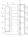
本実施形態の配線モジュール20は、図1に示すように、複数の単電池11を並べて構成された単電池群13に取付けられて電池モジュール10を構成するものであり、この電池モジュール10は、例えば、電気自動車またはハイブリッド自動車等の駆動源として使用される。以下では、上下方向については、図2を基準とし、図3の下方を前方、上方を後方として説明する。
<Embodiment>
An embodiment of the
As shown in FIG. 1, the
(電池モジュール)
電池モジュール10は、図1に示すように、横並びに配列された複数個の単電池11からなる単電池群13と、単電池群13の上面に組み付けられる複数の配線モジュール20とを備えて構成されている。
単電池11は、内部に図示しない発電要素が収容された直方体状の本体部の上面から垂直に突出する一対の電極端子12A,12Bを有する。
(Battery module)
As shown in FIG. 1, the
The
電極端子12A,12B(正極を12A,負極を12Bとして図示)は、本体部の前部及び後部に設けられており、外周にネジ溝を有する円柱形状(ボルト状)をなす。
各単電池11の極性(正負)の向きは、互いに隣り合う単電池11が逆向きになるように配置されており、これにより、互いに異極の電極端子12A,12Bが隣り合うように構成されている。これら複数の単電池11は図示しない保持板によって固定されている。
このように構成された単電池群13は電極端子12A,12Bが2列に並んでおり、各列に対して配線モジュール20をそれぞれ組み付けることにより、複数の単電池11が直列に接続される。
The direction of the polarity (positive / negative) of each
In the
(配線モジュール)
配線モジュール20(以下では図1における下方(前方)の配線モジュール20について説明する)は、図3に示すように、左右に隣り合う電極端子12A,12B間を接続する複数の接続部材21と、各接続部材21に重ねられ電線の端末部に接続されて単電池11の電圧を検知する複数の電圧検知端子23と、接続部材21及び電圧検知端子23が収容される複数の連結部材26を連結して構成される合成樹脂製の樹脂プロテクタ25と、を備えて構成されている。これにより、配線モジュール20は、各連結部材26に接続部材21及び電圧検知端子23が配されてなる連結ユニット20Aが左右に連結されて構成されている。
(Wiring module)
As shown in FIG. 3, the wiring module 20 (hereinafter, the lower (front)
接続部材21は、銅、銅合金、アルミニウム等の金属からなり、概ね長方形の板状をなし、電極端子12A,12Bが通される一対の通し孔22が貫通形成されている。各通し孔22は、共に単電池11の並び方向である左右方向に長い長円形状をなす。
電圧検知端子23は、単電池11の電圧を検知するために設けられており、矩形状の金属板材に電線(図示しない)が圧着等の公知の接続手段により接続されている。
The
The
電圧検知端子23の中心部には、ボルトが挿通される通し孔24が貫通形成されている。通し孔24は、左右方向に長い長円形状をなし、接続部材21の一方の通し孔22に重ねられる。
電線は、被覆電線であって、端末部において絶縁被覆(絶縁層)を剥ぎ取り露出させた導体が電圧検知端子23に接続されている。
A through
The electric wire is a covered electric wire, and a conductor from which the insulating coating (insulating layer) has been peeled and exposed at the terminal portion is connected to the
(樹脂プロテクタ)
樹脂プロテクタ25は、合成樹脂製であって、5個(複数)の連結部材26が左右に連結されて構成されている。
5個の連結部材26は、共に同一形状であって、各接続部材21及び各電圧検知端子23を保持する保持部27と、電圧検知端子23に接続された電線が収容される逆T字状の電線収容部30と、保持部27と電線収容部30との間に介設されて強度を高める補強部35と、保持部27及び補強部35を覆うカバー部55と、を備える。
(Resin protector)
The
The five connecting
保持部27は、接続部材21が載置され、電極端子12A,12Bの台座部分を挿通可能な開口部が左右一対形成された底板(図示しない)と、接続部材21を外部と仕切る仕切り壁28とを備える。
仕切り壁28は、工具等が電極端子12A,12B,接続部材21及び電圧検知端子23に接触して短絡することを防止するために、工具等の接触が防止される高さで設けられるものであり、前方及び左方を開放し、後方及び右方を包囲するように接続部材21の周囲に立設されている。開放された左方側については、隣の連結部材26の右方の仕切り壁28が開放された部分に隣接するように配されるため、隣り合う接続部材21間は、仕切り壁28により仕切られるようになっている。
The holding
The
仕切り壁28の内面には、規制片29が設けられている。この規制片29の下側に接続部材21が配されることで接続部材21の離脱が規制される。
電線収容部30は、保持部27に連なる電線導入部31と、電線導入部31に導入された電線が配策される電線配策部32とを備えており、逆T字状の電線収容溝(図示しない)がヒンジ33を介して接続された逆T字状の溝蓋34で覆われている。
A regulating
The electric
補強部35は、図9に示すように、電線導入部31の左右に所定の厚みで設けられている。
補強部35の右端部(連結部材の並び方向の一端側)には、右方(連結部材の並び方向)に突出する一対の連結突片46,47及びガイド突片48が設けられている。
一方、補強部35の左端部(連結部材26の並び方向の他端側)には、図3に示すように、隣の連結部材26の一対の連結突片46,47及びガイド突片48が挿通される連結挿通部36及びガイド受け部41が設けられている。
As shown in FIG. 9, the reinforcing
A pair of connecting projecting
On the other hand, at the left end portion of the reinforcing portion 35 (the other end side in the direction in which the connecting
連結挿通部36は、図10に示すように、各連結突片46,47を挿通可能な大きさで形成されており、連結突片46,47の上側に配される上壁37と、上壁37の奥端から下方に延びる奥壁38と、連結突片46,47の下側に配される係合壁39とを備える。
係合壁39は、金型の抜きを可能とするために、上壁37に対しては左方に位置をずらし、奥壁38に対しては、下方に位置をずらして形成されている。
As shown in FIG. 10, the connecting
The
この係合壁39の上端は、樹脂プロテクタ25を撓み変形させる際に、連結突片46,47の下端の後述する切欠部49に係合して、樹脂プロテクタ25の過度の撓み変形を規制する。
また、連結挿通部36は、図5に示すように、互いに向かい合う方向に突出する一対の被係止部40A,40Bを有する。
被係止部40A,40Bは、上壁37及び奥壁43に連なるように設けられており、連結突片46,47側に鉤状に突出している。
When the
Moreover, the
The locked
ガイド受け部41は、図6に示すように、ガイド突片48を挿通可能な大きさで形成されており、ガイド突片48の上方に配される上壁42と、上壁42の奥端から下方に延びる奥壁43と、ガイド突片48の下方に配される係合壁44と、を備える。
係合壁44は、金型の抜きを可能とするために、上壁42に対しては左方に位置をずらし、奥壁43に対しては、下方に位置をずらして形成されている。
この係合壁44は、樹脂プロテクタ25を撓み変形させる際に、ガイド突片48の下端の切欠部49に当接して、樹脂プロテクタ25の過度の撓み変形を規制する。
As shown in FIG. 6, the
The
When the
一対の連結突片46,47及びガイド突片48は、共に上下方向(配線モジュール20の組み付け方向)に厚肉であって、前後方向(組み付け方向と直交する方向)に薄肉に形成されている。連結突片46,47は、前後方向に薄肉の形状ゆえに、前後方向に撓み変形可能になっている。一対の連結突片46,47は、その各基端部間にわずかな隙間を有しており、先端側に向けて互いに離間する(広がる)方向に傾斜している。
The pair of connecting projecting
連結突片46,47及びガイド突片48の下側には、この下端を傾斜状に切欠いた切欠部49が形成されている。
切欠部49は、連結突片46,47及びガイド突片48の上下方向の寸法を先端側に向かう程短くするように下端側を切欠いて形成されている。より詳しくは、切欠部49は、連結突片46,47及びガイド突片48が、連結部材26が正常に連結される位置である正規連結位置まで(左右方向に)連結挿通部36に挿通された際に、連結突片46,47の切欠部49と係合壁39,44の上端との間に所定のクリアランスCLを形成する大きさで切欠かれている。
On the lower side of the connecting projecting
The
所定のクリアランスCLは、配線モジュール20の組み付けの際に、配線モジュール20(樹脂プロテクタ25)を組み付け方向とは反対側に撓ませて、連結ユニット20Aを複数の単電池11に1個ずつ順番に組み付けやすい寸法に設定されるものであり、例えば、電極端子12A,12Bの高さ等に応じて撓ませる必要がある大きさに設定される。
一方、一対の連結突片46,47及びガイド突片48は、上方側については、切欠部49が設けられておらず、上端50がほぼ水平方向に延出されているため、樹脂プロテクタ25の組み付け方向に撓もうとする力に対しては、同様に水平方向に延出された上壁37の下面に当接することで、樹脂プロテクタ25の組み付け方向については撓み変形が抑制される。
The predetermined clearance CL is obtained by bending the wiring module 20 (resin protector 25) in the direction opposite to the assembling direction when the
On the other hand, the pair of connecting projecting
また、一対の連結突片46,47の各先端部には、互いに背き合う方向に突出する係止部51,52が設けられている。係止部51,52は、図5に示すように、連結挿通部36に設けられた被係止部40A,40Bに係止可能な形状であって、互いに背き合う方向に段差状に突出する段差部53と、段差部53の先方にて傾斜状に突出寸法が小さくなる傾斜部54とを有する。なお、ガイド突片48及びガイド受け部41には、係止部51,52及び被係止部40A,40Bに対応する左右方向(並び方向)の移動を規制する構成は設けられていない。
In addition, locking
樹脂プロテクタ25を上方(組み付け方向とは反対側)に撓ませようとする力が生じた際に、隣り合う連結部材26間が相対的に離間する方向に移動すると、上方への撓み変形が大きくなりすぎたり、隣り合う連結部材26間の連結が解除される不具合が懸念される。また、樹脂プロテクタ25を下方(組み付け方向)に撓ませようとする力が生じた際に、隣り合う連結部材26間が相対的に離間する方向に移動すると、組み付けの際に撓ませたくない下方についても樹脂プロテクタ25が撓んでしまうことが懸念される。
When a force that causes the
一方、本実施形態では、連結突片46,47が連結挿通部36に挿通されると、連結突片46,47が被係止部40A,40Bに当接して撓み、連結突片46,47が正規連結位置まで挿通されて連結部材26が連結された状態では、連結突片46,47が復元変形して係止部51,52が被係止部40A,40Bの挿入方向の前方に配される。これにより、樹脂プロテクタ25を組み付け方向とは反対側に撓ませようとする力に対しては、被係止部40A,40Bが係止部51,52に係止されることにより、過度の撓みや隣り合う連結部材26間の連結の解除を防止することができる。また、樹脂プロテクタ25を組み付け方向に撓ませようとする力に対しては、連結部材26間の相対的な移動が規制されることで樹脂プロテクタ25の撓み変形を抑制することができる。
On the other hand, in this embodiment, when the connecting
カバー部55は、図3に示すように、保持部27にヒンジ55Aを介して接続されており、カバー本体56と、カバー本体56における並び方向の一方の側に突出するカバー係合部57と、隣り合う連結部材26のカバー係合部57と係合するカバー被係合部60とを有している。
カバー本体56のカバー係合部57が配される一方の角部は、矩形状に切欠かれている。
As shown in FIG. 3, the
One corner where the
カバー係合部57は、カバー本体56の矩形状に切欠かれた部分に設けられており、図8に示すように、並び方向に突出する板状突片58と、板状突片58の先端部にて下方に突出するカバー係止部59とを備えている。
板状突片58は、左右方向に長い長方形の板状であり、その先端部は、幅方向の両端部がテーパ状に角が取られている。
The
The plate-like projecting
この板状突片58の突出方向は、自然状態(外力が作用していない状態)において、水平方向(左右方向)に対して上方側に傾斜している。
カバー係止部59は、段差状に突出し、先端側に向けて突出寸法が小さくなる形状をなす。
カバー被係合部60は、カバー係合部57とは、カバー本体56のうち連結部材26の並び方向における反対側に設けられており、図7に示すように、カバー係合部57が挿通されるカバー挿通部61と、カバー係止部59が配される係止孔62とを有する。
The protruding direction of the plate-like protruding
The
The cover engaged
カバー挿通部61は、カバー本体56を挿通できるように設けられた高さ位置の異なる第1挿通部61Aと第2挿通部61Bとからなり、第1挿通部61Aは、カバー本体56とは異なる高さ位置に設けられ、第2挿通部61Bは、カバー本体56と面一に設けられている。第1挿通部61Aの下方には、金型の抜きのためにカバー本体56を貫通する抜き孔56Aが形成されている。
The cover insertion portion 61 includes a
係止孔62は、カバー本体56を貫通する貫通孔であり、カバー係止部59の形状に応じて前後方向に長い長方形状とされている。
そして、カバー挿通部61にカバー係合部57が正規連結位置まで挿通されることにより、係止孔62にカバー係止部59が配され、隣り合うカバー部55が連結される。このとき、隣り合うカバー部55が離間する方向の力に対しては、係止孔62の孔縁にカバー係止部59が係止されることにより、カバー部55の連結状態が保持される。
The locking
Then, when the
次に、配線モジュール20の組み付けについて説明する。
まず、接続部材21を保持部27のうち仕切り壁28が設けられていない側方側から左右方向に挿入し、接続部材21を保持部27内に保持する。
次に、カバー係合部57をカバー被係合部60に係合させるとともに、連結部材26のガイド突片48及び連結突片46,47を隣の連結部材26のガイド受け部41及び連結挿通部36に挿通する。
Next, assembly of the
First, the connecting
Next, the
この連結の際の順番は、まず、カバー係合部57の板状突片58をカバー被係合部60のカバー挿通部61に挿通し、その後、ガイド突片48をガイド受け部41に挿通し、次に、連結突片46,47を連結挿通部36に挿通する。
In this connection, first, the plate-
そして、板状突片58がカバー挿通部61に、ガイド突片48をガイド受け部41、連結突片46,47が連結挿通部36に、共に正規連結位置まで挿通されると、隣り合う連結部材26が正規に連結された状態となる。同様に連結すべき全ての連結部材26について連結することで複数の接続部材21が収容された状態の樹脂プロテクタ25が形成される。
When the plate-
次に、電線の端末に接続された電圧検知端子23を接続部材21に重ねて装着し、溝蓋34を開けて電線を電線収容溝に通し、電線を配策したら溝蓋34を閉じる。
これにより、複数の連結ユニット20Aが連結された配線モジュール20が形成される(図2)。
Next, the
Thereby, the
そして、配線モジュール20を、持ち上げ、単電池群13の上方に移動させる。この移動の際には、連結突片46,47が被係止部40A,40Bにより左右方向に係止された状態で連結挿通部36の上壁37と連結突片46,47の上端50、及び、ガイド受け部41の上壁42及びガイド突片48の上端50とが当接することにより下方への撓み変形が抑制されているため、配線モジュール20は、ほぼ水平な状態で持ち上げられる。
Then, the
次に、単電池群13の上方では、図11に示すように、配線モジュール20(の樹脂プロテクタ25)のうち、一方の端部側(の連結部材26)を水平な状態とし、他方の端部側を上方に撓み変形させる。このとき、連結突片46,47及びガイド突片48の下端の切欠部49と、係合壁39,44との間には、所定のクリアランスCLが設けられているため、このクリアランスCLにより配線モジュール20(の樹脂プロテクタ25)を容易に撓ませることができる(図12)。
Next, above the
そして、配線モジュール20の一端側の連結部材26から順番に他端側の連結部材26まで各単電池11の電極端子12A,12Bを接続部材21及び電圧検知端子23の通し孔22,24に通して組み付け、電極端子12A,12Bをナットで締結する。その後、カバー部55を閉じる。これにより、単電池群13に配線モジュール20が組み付けられた電池モジュール10が形成される(図1)。
Then, the
上記実施形態の構成によれば、以下の作用・効果を奏する。
(1)正極及び負極の電極端子12A,12Bを有する複数の単電池11からなる単電池群13に組み付けられる配線モジュール20であって、複数の単電池11に電気的に接続される複数の電線が配策される樹脂プロテクタ25を備え、樹脂プロテクタ25は、複数の連結部材26が連結されて構成されるものであり、各連結部材26は、当該連結部材26における並び方向の一端側に設けられて並び方向に突出する連結突片46,47と、連結部材26における並び方向の他端側に設けられて隣り合う連結部材26の連結突片46,47が挿通される連結挿通部36とを備えており、連結突片46,47は、連結挿通部36に挿通された状態で、単電池群13への組み付け方向における連結挿通部36との間にクリアランスCLを形成する切欠部49を有し、所定のクリアランスCLにより樹脂プロテクタ25における単電池群13への組み付け方向とは反対側への撓み変形が許容される。
According to the structure of the said embodiment, there exist the following effects.
(1) A
本実施形態によれば、所定のクリアランスCLにより樹脂プロテクタ25における単電池群13への組み付け方向とは反対側への撓み変形が許容されるため、単電池群13に対して連結部材26の並び方向の一方の側から他方の側へと順番に組み付けていく作業が容易になる。よって、配線モジュール20の単電池群13への組み付け作業性を向上させることが可能となる。
なお、樹脂プロテクタ25における単電池群13への組み付け方向については、切欠部49を設けないことで所定のクリアランスCLを形成しないようにすれば、樹脂プロテクタ25における単電池群13への組み付け方向の撓み変形を規制することができる。よって、例えば、単電池群13への組み付けの前に樹脂プロテクタ25を持ち上げた際における組み付け方向の撓み変形を規制できるため、配線モジュール20の組み付け位置への移動の際の作業性の低下を抑制できる。
According to the present embodiment, the predetermined clearance CL allows the
In addition, about the assembly direction to the
(2)連結突片46,47は、単電池群13への組み付け方向について厚肉の形状である。
このようにすれば、組み付け方向や組み付け方向とは反対方向への力に対する連結突片46,47の剛性を高めることができる。
(2) The connecting
In this way, it is possible to increase the rigidity of the connecting
(3)連結突片46,47は、単電池群13への組み付け方向とは直交する方向である肉薄とされた方向に撓み変形可能であり、連結突片46,47の先端部には、連結挿通部36の被係止部40A,40Bに係止する係止部51,52が肉薄とされた方向に突出している。
このようにすれば、連結部材26を連結状態に保持することができる。
(3) The connecting
In this way, the connecting
(4)連結突片46,47は、一対設けられており、一対の連結突片46,47に設けられる各係止部51,52は、互いに背き合う方向に突出している。
このようにすれば、簡素な構成で、連結部材26の連結状態を保持することができる。
(4) A pair of
If it does in this way, the connection state of connecting
(5)各連結部材26には、連結突片46,47に沿って突出するガイド突片48と、隣り合う連結部材26のガイド突片48が挿通されるガイド受け部41とを備えており、隣り合う連結部材26の連結の際には、連結突片46,47の先端部が連結挿通部36に挿通されるよりも先に、ガイド突片48の先端部がガイド受け部41に挿通される。
このようにすれば、隣り合う連結部材26の連結の際に、連結突片46,47の先端部が連結挿通部36に挿通されるよりも先に、ガイド突片48の先端部がガイド受け部41に挿通されるため、ガイド突片48を目安に連結部材26を連結することが可能になる。よって、連結部材26の連結の際の作業性を向上させることが可能になる。
(5) Each
In this way, when the adjacent connecting
(6)各連結部材26は、電極端子12A,12B間を接続する接続部材21を保持する保持部27と、保持部27に被せられるカバー部55とを備えており、カバー部55には、連結部材26の並び方向に向けて突出するカバー係合部57と、隣り合う連結部材26のカバー係合部57と係合するカバー被係合部60とを有し、カバー係合部57の突出方向は、カバー部55を開いた状態において単電池群13への組み付け方向とは反対側に傾斜している。
このようにすれば、樹脂プロテクタ25を撓ませた際に、カバー係合部57とカバー被係合部60との係合が解除されるという不具合が発生することを抑制することが可能になる。
(6) Each connecting
If it does in this way, when the
<他の実施形態>
本発明は上記記述及び図面によって説明した実施形態に限定されるものではなく、例えば次のような実施形態も本発明の技術的範囲に含まれる。
(1)上記実施形態では、連結突片46,47,ガイド突片48及びカバー係合部57を連結部材26の右端側に設け、連結挿通部36,ガイド受け部41及びカバー被係合部60を連結部材26の左端側に設けたが、これとは反対に、連結突片46,47,ガイド突片48及びカバー係合部57を連結部材26の左端側に設け、連結挿通部36,ガイド受け部41及びカバー被係合部60を連結部材26の右端側に設けるようにしてもよい。また、これらのいずれかを左右に入れ替えるようにしてもよい。
<Other embodiments>
The present invention is not limited to the embodiments described with reference to the above description and drawings. For example, the following embodiments are also included in the technical scope of the present invention.
(1) In the above embodiment, the connecting
(2)上記実施形態では、接続部材21は、異極の電極端子12A,12Bを接続(直列接続)するものとしたが、これに限られず、同極の電極端子12A,12Bを接続(並列接続)するものでもよい。例えば、上記実施形態の電池モジュール10に更に別の単電池11を並列接続し、この並列接続における同極の電極端子12A,12BA(B)を複数の接続部材21で接続するようにしたものでもよい。
(2) In the above embodiment, the
(3)電池モジュール10を構成する単電池11の数については、上記実施形態の個数に限られず、配線モジュール20についても単電池11の個数に応じて連結ユニット20A(連結部材26)の個数を適宜変更することができる。
(4)上記実施形態では、電極端子12A,12Bに接続部材21を挿通してナットで締結する構成であったが、これに限らず、単電池11についてナット型の電極端子を備える構成とし、ボルトを電極端子に締結するようにしてもよい。
(3) The number of
(4) In the above embodiment, the
10…電池モジュール
11…単電池
12A,12B…電極端子
13…単電池群
20…配線モジュール
20A…連結ユニット
21…接続部材
23…電圧検知端子
25…樹脂プロテクタ
26…連結部材
27…保持部
28…仕切り壁
30…電線収容部
32…電線配策部
35…補強部
36…連結挿通部
37…上壁
39…係合壁
40A,40B…被係止部
41…ガイド受け部
42…上壁
44…係合壁
46,47…連結突片
48…ガイド突片
49…切欠部
51,52…係止部
55…カバー部
56…カバー本体
57…カバー係合部
58…板状突片
59…カバー係止部
60…カバー被係合部
61…カバー挿通部
61A…第1挿通部
61B…第2挿通部
62…係止孔
CL…クリアランス
DESCRIPTION OF
Claims (5)
前記複数の単電池に電気的に接続される複数の電線が配策される樹脂プロテクタを備え、
前記樹脂プロテクタは、複数の連結部材が連結されて構成されるものであり、
前記各連結部材は、当該連結部材における並び方向の一端側に設けられて前記並び方向に突出する連結突片と、前記連結部材における並び方向の他端側に設けられて隣り合う前記連結部材の前記連結突片が挿通される連結挿通部とを備えており、
前記連結突片は、前記連結挿通部に挿通された状態で、前記単電池群への組み付け方向における前記連結挿通部との間に所定のクリアランスを形成する切欠部を有し、前記切欠部は、前記連結突片の上下方向の寸法を先端側に向かう程短くなるように下端側を切り欠き、前記連結突片の上端側は、前記切欠部を設けないようにするとともに、前記連結挿通部は、前記連結突片の上側に配される上壁と、前記連結突片の下側に配される係合壁とを備え、前記所定のクリアランスは、前記連結突片と前記係合壁との間に形成され、前記所定のクリアランスにより前記樹脂プロテクタにおける前記単電池群への組み付け方向とは反対側への撓み変形が許容されており、
前記連結突片は、前記単電池群への組み付け方向の寸法が前記組み付け方向と直交する方向の寸法よりも大きい配線モジュール。 A wiring module assembled to a unit cell group composed of a plurality of unit cells having positive and negative electrode terminals,
A resin protector in which a plurality of electric wires electrically connected to the plurality of single cells are arranged,
The resin protector is configured by connecting a plurality of connecting members,
Each of the connecting members is provided on one end side in the arranging direction of the connecting member and protrudes in the arranging direction, and on the other end side of the connecting member in the arranging direction. A connection insertion portion through which the connection protrusion is inserted;
The coupling protrusion in a state where the inserted into the coupling insertion portion, said has a cutout portion for forming a predetermined clearance between the connection insertion portion in the mounting direction of the cell group, wherein the cutout In addition, the lower end side is cut out so that the vertical dimension of the connecting projection piece becomes shorter toward the tip end side, and the upper end side of the connecting projection piece is not provided with the notch portion, and the connecting insertion portion Comprises an upper wall disposed on the upper side of the connecting projection piece, and an engagement wall disposed on the lower side of the connecting projection piece, and the predetermined clearance includes the connecting projection piece and the engaging wall. Is formed between, and by the predetermined clearance, bending deformation to the side opposite to the assembly direction to the unit cell group in the resin protector is allowed ,
The connection projection piece is a wiring module in which a dimension in an assembly direction to the unit cell group is larger than a dimension in a direction orthogonal to the assembly direction .
前記複数の単電池に電気的に接続される複数の電線が配策される樹脂プロテクタを備え、
前記樹脂プロテクタは、複数の連結部材が連結されて構成されるものであり、
前記各連結部材は、当該連結部材における並び方向の一端側に設けられて前記並び方向に突出する連結突片と、前記連結部材における並び方向の他端側に設けられて隣り合う前記連結部材の前記連結突片が挿通される連結挿通部とを備えており、
前記連結突片は、前記連結挿通部に挿通された状態で、前記単電池群への組み付け方向における前記連結挿通部との間に所定のクリアランスを形成する切欠部を有し、前記切欠部は、前記連結突片の上下方向の寸法を先端側に向かう程短くなるように下端側を切り欠き、前記連結突片の上端側は、前記切欠部を設けないようにするとともに、前記連結挿通部は、前記連結突片の上側に配される上壁と、前記連結突片の下側に配される係合壁とを備え、前記所定のクリアランスは、前記連結突片と前記係合壁との間に形成され、前記所定のクリアランスにより前記樹脂プロテクタにおける前記単電池群への組み付け方向とは反対側への撓み変形が許容されており、
前記各連結部材には、前記連結突片に沿って突出するガイド突片と、隣り合う前記連結部材の前記ガイド突片が挿通されるガイド受け部とを備えており、前記隣り合う連結部材の連結の際には、前記連結突片の先端部が前記連結挿通部に挿通されるよりも先に、前記ガイド突片の先端部が前記ガイド受け部に挿通される配線モジュール。 A wiring module assembled to a unit cell group composed of a plurality of unit cells having positive and negative electrode terminals,
A resin protector in which a plurality of electric wires electrically connected to the plurality of single cells are arranged,
The resin protector is configured by connecting a plurality of connecting members,
Each of the connecting members is provided on one end side in the arranging direction of the connecting member and protrudes in the arranging direction, and on the other end side of the connecting member in the arranging direction. A connection insertion portion through which the connection protrusion is inserted;
The connection protrusion has a notch portion that forms a predetermined clearance with the connection insertion portion in the assembly direction to the unit cell group in a state of being inserted into the connection insertion portion, In addition, the lower end side is cut out so that the vertical dimension of the connecting projection piece becomes shorter toward the tip end side, and the upper end side of the connecting projection piece is not provided with the notch portion, and the connecting insertion portion Comprises an upper wall disposed on the upper side of the connecting projection piece, and an engagement wall disposed on the lower side of the connecting projection piece, and the predetermined clearance includes the connecting projection piece and the engaging wall. Is formed between, and by the predetermined clearance, bending deformation to the side opposite to the assembly direction to the unit cell group in the resin protector is allowed,
Each of the connection members includes a guide protrusion that protrudes along the connection protrusion, and a guide receiving portion through which the guide protrusion of the adjacent connection member is inserted. In the connection, the wiring module in which the tip of the guide protrusion is inserted into the guide receiving portion before the tip of the connection protrusion is inserted into the connection insertion portion .
前記複数の単電池に電気的に接続される複数の電線が配策される樹脂プロテクタを備え、
前記樹脂プロテクタは、複数の連結部材が連結されて構成されるものであり、
前記各連結部材は、当該連結部材における並び方向の一端側に設けられて前記並び方向に突出する連結突片と、前記連結部材における並び方向の他端側に設けられて隣り合う前記連結部材の前記連結突片が挿通される連結挿通部とを備えており、
前記連結突片は、前記連結挿通部に挿通された状態で、前記単電池群への組み付け方向における前記連結挿通部との間に所定のクリアランスを形成する切欠部を有し、前記切欠部は、前記連結突片の上下方向の寸法を先端側に向かう程短くなるように下端側を切り欠き、前記連結突片の上端側は、前記切欠部を設けないようにするとともに、前記連結挿通部は、前記連結突片の上側に配される上壁と、前記連結突片の下側に配される係合壁とを備え、前記所定のクリアランスは、前記連結突片と前記係合壁との間に形成され、前記所定のクリアランスにより前記樹脂プロテクタにおける前記単電池群への組み付け方向とは反対側への撓み変形が許容されており、
前記各連結部材は、前記電極端子間を接続する接続部材を保持する保持部と、前記保持部に被せられるカバー部とを備えており、
前記カバー部には、前記連結部材の並び方向に向けて突出するカバー係合部と、隣り合う連結部材の前記カバー係合部と係合するカバー被係合部とを有し、
前記カバー係合部の突出方向は、前記カバー部を開いた状態において前記単電池群への組み付け方向とは反対側に傾斜している配線モジュール。 A wiring module assembled to a unit cell group composed of a plurality of unit cells having positive and negative electrode terminals,
A resin protector in which a plurality of electric wires electrically connected to the plurality of single cells are arranged,
The resin protector is configured by connecting a plurality of connecting members,
Each of the connecting members is provided on one end side in the arranging direction of the connecting member and protrudes in the arranging direction, and on the other end side of the connecting member in the arranging direction. A connection insertion portion through which the connection protrusion is inserted;
The connection protrusion has a notch portion that forms a predetermined clearance with the connection insertion portion in the assembly direction to the unit cell group in a state of being inserted into the connection insertion portion, In addition, the lower end side is cut out so that the vertical dimension of the connecting projection piece becomes shorter toward the tip end side, and the upper end side of the connecting projection piece is not provided with the notch portion, and the connecting insertion portion Comprises an upper wall disposed on the upper side of the connecting projection piece, and an engagement wall disposed on the lower side of the connecting projection piece, and the predetermined clearance includes the connecting projection piece and the engaging wall. Is formed between, and by the predetermined clearance, bending deformation to the side opposite to the assembly direction to the unit cell group in the resin protector is allowed,
Each of the connecting members includes a holding portion that holds a connection member that connects the electrode terminals, and a cover portion that covers the holding portion,
The cover portion includes a cover engaging portion that protrudes in the direction in which the connecting members are arranged, and a cover engaged portion that engages with the cover engaging portion of an adjacent connecting member,
The wiring module in which the protruding direction of the cover engaging portion is inclined to the side opposite to the mounting direction to the unit cell group when the cover portion is opened .
Priority Applications (1)
| Application Number | Priority Date | Filing Date | Title |
|---|---|---|---|
| JP2011240190A JP5673495B2 (en) | 2011-11-01 | 2011-11-01 | Wiring module |
Applications Claiming Priority (1)
| Application Number | Priority Date | Filing Date | Title |
|---|---|---|---|
| JP2011240190A JP5673495B2 (en) | 2011-11-01 | 2011-11-01 | Wiring module |
Publications (2)
| Publication Number | Publication Date |
|---|---|
| JP2013098030A JP2013098030A (en) | 2013-05-20 |
| JP5673495B2 true JP5673495B2 (en) | 2015-02-18 |
Family
ID=48619761
Family Applications (1)
| Application Number | Title | Priority Date | Filing Date |
|---|---|---|---|
| JP2011240190A Expired - Fee Related JP5673495B2 (en) | 2011-11-01 | 2011-11-01 | Wiring module |
Country Status (1)
| Country | Link |
|---|---|
| JP (1) | JP5673495B2 (en) |
Families Citing this family (2)
| Publication number | Priority date | Publication date | Assignee | Title |
|---|---|---|---|---|
| JP6477858B1 (en) | 2017-12-28 | 2019-03-06 | 株式会社オートネットワーク技術研究所 | Connection module |
| JP7184606B2 (en) * | 2018-11-20 | 2022-12-06 | 日本メクトロン株式会社 | Support member and battery module |
Family Cites Families (6)
| Publication number | Priority date | Publication date | Assignee | Title |
|---|---|---|---|---|
| JP2010225449A (en) * | 2009-03-24 | 2010-10-07 | Autonetworks Technologies Ltd | Connection unit |
| JP5500336B2 (en) * | 2009-06-23 | 2014-05-21 | 株式会社オートネットワーク技術研究所 | Battery connection assembly |
| JP2011049047A (en) * | 2009-08-27 | 2011-03-10 | Autonetworks Technologies Ltd | Battery connection assembly |
| JP5813302B2 (en) * | 2009-09-07 | 2015-11-17 | 矢崎総業株式会社 | Bus bar module and power supply device including the bus bar module |
| JP5504977B2 (en) * | 2010-03-02 | 2014-05-28 | 株式会社オートネットワーク技術研究所 | Battery connection assembly |
| JP2011210710A (en) * | 2010-03-12 | 2011-10-20 | Autonetworks Technologies Ltd | Battery module |
-
2011
- 2011-11-01 JP JP2011240190A patent/JP5673495B2/en not_active Expired - Fee Related
Also Published As
| Publication number | Publication date |
|---|---|
| JP2013098030A (en) | 2013-05-20 |
Similar Documents
| Publication | Publication Date | Title |
|---|---|---|
| JP5834769B2 (en) | Battery wiring module | |
| CN102782899B (en) | Battery connection assembly | |
| JP5494748B2 (en) | Battery wiring module | |
| JP5772524B2 (en) | Battery wiring module | |
| JP5803630B2 (en) | Battery wiring module | |
| JP5787140B2 (en) | Battery wiring module | |
| JP5720530B2 (en) | Battery wiring module | |
| JP6075150B2 (en) | Wiring module | |
| JP2013033707A (en) | Battery wiring module | |
| JP5812428B2 (en) | Electrical junction box | |
| JP5696691B2 (en) | Electrical junction box | |
| JP5720448B2 (en) | Battery wiring module | |
| US20190198842A1 (en) | Connection module | |
| WO2014024760A1 (en) | Battery wiring module | |
| JP2012227002A (en) | Wiring module | |
| JP5796746B2 (en) | Wiring module | |
| WO2015163113A1 (en) | Wiring module | |
| JP5673464B2 (en) | Battery wiring module | |
| JP5673465B2 (en) | Battery wiring module | |
| JP5673495B2 (en) | Wiring module | |
| JP2020035610A (en) | Battery wiring module | |
| JP5648610B2 (en) | Battery wiring module | |
| JP5757180B2 (en) | Battery wiring module cover, battery wiring module and battery module | |
| JP5672188B2 (en) | Battery wiring module | |
| JP2012186063A (en) | Battery connection assembly |
Legal Events
| Date | Code | Title | Description |
|---|---|---|---|
| A621 | Written request for application examination |
Free format text: JAPANESE INTERMEDIATE CODE: A621 Effective date: 20140303 |
|
| A977 | Report on retrieval |
Free format text: JAPANESE INTERMEDIATE CODE: A971007 Effective date: 20140910 |
|
| A131 | Notification of reasons for refusal |
Free format text: JAPANESE INTERMEDIATE CODE: A131 Effective date: 20140916 |
|
| A521 | Request for written amendment filed |
Free format text: JAPANESE INTERMEDIATE CODE: A523 Effective date: 20141106 |
|
| TRDD | Decision of grant or rejection written | ||
| A01 | Written decision to grant a patent or to grant a registration (utility model) |
Free format text: JAPANESE INTERMEDIATE CODE: A01 Effective date: 20141202 |
|
| A61 | First payment of annual fees (during grant procedure) |
Free format text: JAPANESE INTERMEDIATE CODE: A61 Effective date: 20141215 |
|
| R150 | Certificate of patent or registration of utility model |
Ref document number: 5673495 Country of ref document: JP Free format text: JAPANESE INTERMEDIATE CODE: R150 |
|
| LAPS | Cancellation because of no payment of annual fees |