JP5671004B2 - Porous composite membrane - Google Patents
Porous composite membrane Download PDFInfo
- Publication number
- JP5671004B2 JP5671004B2 JP2012506091A JP2012506091A JP5671004B2 JP 5671004 B2 JP5671004 B2 JP 5671004B2 JP 2012506091 A JP2012506091 A JP 2012506091A JP 2012506091 A JP2012506091 A JP 2012506091A JP 5671004 B2 JP5671004 B2 JP 5671004B2
- Authority
- JP
- Japan
- Prior art keywords
- microporous membrane
- filter member
- layer
- membrane
- nanofiber
- Prior art date
- Legal status (The legal status is an assumption and is not a legal conclusion. Google has not performed a legal analysis and makes no representation as to the accuracy of the status listed.)
- Active
Links
- 239000012528 membrane Substances 0.000 title claims description 155
- 239000002131 composite material Substances 0.000 title description 11
- 239000010410 layer Substances 0.000 claims description 348
- 239000002121 nanofiber Substances 0.000 claims description 327
- 239000012982 microporous membrane Substances 0.000 claims description 288
- KFZMGEQAYNKOFK-UHFFFAOYSA-N Isopropanol Chemical compound CC(C)O KFZMGEQAYNKOFK-UHFFFAOYSA-N 0.000 claims description 246
- 239000002245 particle Substances 0.000 claims description 190
- 230000014759 maintenance of location Effects 0.000 claims description 151
- 238000012360 testing method Methods 0.000 claims description 100
- 239000007788 liquid Substances 0.000 claims description 95
- 229920001778 nylon Polymers 0.000 claims description 85
- 239000004677 Nylon Substances 0.000 claims description 84
- 239000004094 surface-active agent Substances 0.000 claims description 71
- 239000002356 single layer Substances 0.000 claims description 59
- 238000007873 sieving Methods 0.000 claims description 54
- 239000011148 porous material Substances 0.000 claims description 41
- 229920000642 polymer Polymers 0.000 claims description 31
- 239000004952 Polyamide Substances 0.000 claims description 27
- 229920002647 polyamide Polymers 0.000 claims description 27
- XLYOFNOQVPJJNP-UHFFFAOYSA-N water Substances O XLYOFNOQVPJJNP-UHFFFAOYSA-N 0.000 claims description 26
- -1 polyethylene Polymers 0.000 claims description 24
- 239000011324 bead Substances 0.000 claims description 23
- 239000004793 Polystyrene Substances 0.000 claims description 21
- 239000004816 latex Substances 0.000 claims description 21
- 229920000126 latex Polymers 0.000 claims description 21
- 229920002223 polystyrene Polymers 0.000 claims description 21
- 239000004698 Polyethylene Substances 0.000 claims description 13
- 239000012530 fluid Substances 0.000 claims description 13
- 229920002292 Nylon 6 Polymers 0.000 claims description 12
- 229920004890 Triton X-100 Polymers 0.000 claims description 12
- 239000013504 Triton X-100 Substances 0.000 claims description 12
- 239000004699 Ultra-high molecular weight polyethylene Substances 0.000 claims description 11
- 229920000573 polyethylene Polymers 0.000 claims description 11
- 229920000785 ultra high molecular weight polyethylene Polymers 0.000 claims description 11
- 239000007864 aqueous solution Substances 0.000 claims description 4
- DFUYAWQUODQGFF-UHFFFAOYSA-N 1-ethoxy-1,1,2,2,3,3,4,4,4-nonafluorobutane Chemical compound CCOC(F)(F)C(F)(F)C(F)(F)C(F)(F)F DFUYAWQUODQGFF-UHFFFAOYSA-N 0.000 description 26
- 238000000034 method Methods 0.000 description 26
- 239000000463 material Substances 0.000 description 24
- 238000001914 filtration Methods 0.000 description 23
- 239000000835 fiber Substances 0.000 description 22
- 238000011144 upstream manufacturing Methods 0.000 description 22
- 230000009471 action Effects 0.000 description 16
- 239000000203 mixture Substances 0.000 description 16
- 239000000243 solution Substances 0.000 description 16
- DBMJMQXJHONAFJ-UHFFFAOYSA-M Sodium laurylsulphate Chemical compound [Na+].CCCCCCCCCCCCOS([O-])(=O)=O DBMJMQXJHONAFJ-UHFFFAOYSA-M 0.000 description 13
- 238000005259 measurement Methods 0.000 description 13
- 239000000758 substrate Substances 0.000 description 12
- 238000001523 electrospinning Methods 0.000 description 11
- 229920001343 polytetrafluoroethylene Polymers 0.000 description 11
- 239000004810 polytetrafluoroethylene Substances 0.000 description 11
- 230000007423 decrease Effects 0.000 description 9
- 230000035699 permeability Effects 0.000 description 9
- 230000008569 process Effects 0.000 description 9
- 239000004743 Polypropylene Substances 0.000 description 8
- 229920001155 polypropylene Polymers 0.000 description 8
- 230000000694 effects Effects 0.000 description 7
- 230000007935 neutral effect Effects 0.000 description 7
- 239000004745 nonwoven fabric Substances 0.000 description 7
- 229920006393 polyether sulfone Polymers 0.000 description 7
- 229920000098 polyolefin Polymers 0.000 description 7
- 229920002302 Nylon 6,6 Polymers 0.000 description 6
- KWYUFKZDYYNOTN-UHFFFAOYSA-M Potassium hydroxide Chemical compound [OH-].[K+] KWYUFKZDYYNOTN-UHFFFAOYSA-M 0.000 description 6
- 230000006872 improvement Effects 0.000 description 6
- 239000004695 Polyether sulfone Substances 0.000 description 5
- 101100460551 Saccharomyces cerevisiae (strain ATCC 204508 / S288c) NNF2 gene Proteins 0.000 description 5
- 239000002253 acid Substances 0.000 description 5
- 238000004519 manufacturing process Methods 0.000 description 5
- 101150116468 nnf1 gene Proteins 0.000 description 5
- 229920002120 photoresistant polymer Polymers 0.000 description 5
- 238000001179 sorption measurement Methods 0.000 description 5
- ARXJGSRGQADJSQ-UHFFFAOYSA-N 1-methoxypropan-2-ol Chemical compound COCC(C)O ARXJGSRGQADJSQ-UHFFFAOYSA-N 0.000 description 4
- 238000009826 distribution Methods 0.000 description 4
- 229920005989 resin Polymers 0.000 description 4
- 239000011347 resin Substances 0.000 description 4
- 239000002904 solvent Substances 0.000 description 4
- 238000009987 spinning Methods 0.000 description 4
- 239000000706 filtrate Substances 0.000 description 3
- 239000000499 gel Substances 0.000 description 3
- 238000011068 loading method Methods 0.000 description 3
- 239000000693 micelle Substances 0.000 description 3
- 239000004065 semiconductor Substances 0.000 description 3
- 239000000654 additive Substances 0.000 description 2
- 230000000996 additive effect Effects 0.000 description 2
- 230000008901 benefit Effects 0.000 description 2
- 238000004140 cleaning Methods 0.000 description 2
- 239000011248 coating agent Substances 0.000 description 2
- 238000000576 coating method Methods 0.000 description 2
- 230000003247 decreasing effect Effects 0.000 description 2
- 230000006866 deterioration Effects 0.000 description 2
- 238000011143 downstream manufacturing Methods 0.000 description 2
- 230000005284 excitation Effects 0.000 description 2
- 238000000605 extraction Methods 0.000 description 2
- 239000004744 fabric Substances 0.000 description 2
- 239000012527 feed solution Substances 0.000 description 2
- 238000001506 fluorescence spectroscopy Methods 0.000 description 2
- 238000002347 injection Methods 0.000 description 2
- 239000007924 injection Substances 0.000 description 2
- BDAGIHXWWSANSR-UHFFFAOYSA-N methanoic acid Natural products OC=O BDAGIHXWWSANSR-UHFFFAOYSA-N 0.000 description 2
- 230000003287 optical effect Effects 0.000 description 2
- 238000004626 scanning electron microscopy Methods 0.000 description 2
- 230000008685 targeting Effects 0.000 description 2
- 229920001169 thermoplastic Polymers 0.000 description 2
- 239000004416 thermosoftening plastic Substances 0.000 description 2
- GPRLSGONYQIRFK-MNYXATJNSA-N triton Chemical compound [3H+] GPRLSGONYQIRFK-MNYXATJNSA-N 0.000 description 2
- OSWFIVFLDKOXQC-UHFFFAOYSA-N 4-(3-methoxyphenyl)aniline Chemical compound COC1=CC=CC(C=2C=CC(N)=CC=2)=C1 OSWFIVFLDKOXQC-UHFFFAOYSA-N 0.000 description 1
- LLLVZDVNHNWSDS-UHFFFAOYSA-N 4-methylidene-3,5-dioxabicyclo[5.2.2]undeca-1(9),7,10-triene-2,6-dione Chemical compound C1(C2=CC=C(C(=O)OC(=C)O1)C=C2)=O LLLVZDVNHNWSDS-UHFFFAOYSA-N 0.000 description 1
- 229920006310 Asahi-Kasei Polymers 0.000 description 1
- 239000004215 Carbon black (E152) Substances 0.000 description 1
- IAYPIBMASNFSPL-UHFFFAOYSA-N Ethylene oxide Chemical group C1CO1 IAYPIBMASNFSPL-UHFFFAOYSA-N 0.000 description 1
- WHXSMMKQMYFTQS-UHFFFAOYSA-N Lithium Chemical compound [Li] WHXSMMKQMYFTQS-UHFFFAOYSA-N 0.000 description 1
- 229920010741 Ultra High Molecular Weight Polyethylene (UHMWPE) Polymers 0.000 description 1
- 239000012190 activator Substances 0.000 description 1
- 239000012790 adhesive layer Substances 0.000 description 1
- 229920003231 aliphatic polyamide Polymers 0.000 description 1
- 125000000217 alkyl group Chemical group 0.000 description 1
- 238000004458 analytical method Methods 0.000 description 1
- 239000004760 aramid Substances 0.000 description 1
- 229920003235 aromatic polyamide Polymers 0.000 description 1
- 239000006227 byproduct Substances 0.000 description 1
- 239000001913 cellulose Substances 0.000 description 1
- 229920002678 cellulose Polymers 0.000 description 1
- 239000003795 chemical substances by application Substances 0.000 description 1
- 239000000084 colloidal system Substances 0.000 description 1
- 239000000356 contaminant Substances 0.000 description 1
- 229920001577 copolymer Polymers 0.000 description 1
- 230000002596 correlated effect Effects 0.000 description 1
- 230000000875 corresponding effect Effects 0.000 description 1
- 230000007547 defect Effects 0.000 description 1
- 238000010586 diagram Methods 0.000 description 1
- 238000010790 dilution Methods 0.000 description 1
- 239000012895 dilution Substances 0.000 description 1
- 239000000428 dust Substances 0.000 description 1
- 238000002296 dynamic light scattering Methods 0.000 description 1
- 238000010041 electrostatic spinning Methods 0.000 description 1
- 238000000295 emission spectrum Methods 0.000 description 1
- 238000011156 evaluation Methods 0.000 description 1
- 238000002474 experimental method Methods 0.000 description 1
- 239000011152 fibreglass Substances 0.000 description 1
- 239000010419 fine particle Substances 0.000 description 1
- 238000002189 fluorescence spectrum Methods 0.000 description 1
- 229920002313 fluoropolymer Polymers 0.000 description 1
- 239000004811 fluoropolymer Substances 0.000 description 1
- 230000004907 flux Effects 0.000 description 1
- 235000019253 formic acid Nutrition 0.000 description 1
- 229930195733 hydrocarbon Natural products 0.000 description 1
- 150000002430 hydrocarbons Chemical class 0.000 description 1
- 125000001183 hydrocarbyl group Chemical group 0.000 description 1
- 229920013746 hydrophilic polyethylene oxide Polymers 0.000 description 1
- 125000001165 hydrophobic group Chemical group 0.000 description 1
- 229910052744 lithium Inorganic materials 0.000 description 1
- 239000004750 melt-blown nonwoven Substances 0.000 description 1
- 125000002496 methyl group Chemical group [H]C([H])([H])* 0.000 description 1
- 239000011859 microparticle Substances 0.000 description 1
- 239000012229 microporous material Substances 0.000 description 1
- 239000002105 nanoparticle Substances 0.000 description 1
- 239000003960 organic solvent Substances 0.000 description 1
- 229920005548 perfluoropolymer Polymers 0.000 description 1
- 239000012466 permeate Substances 0.000 description 1
- 229920006122 polyamide resin Polymers 0.000 description 1
- 229920013716 polyethylene resin Polymers 0.000 description 1
- 229920000139 polyethylene terephthalate Polymers 0.000 description 1
- 239000005020 polyethylene terephthalate Substances 0.000 description 1
- 229920005672 polyolefin resin Polymers 0.000 description 1
- 238000011045 prefiltration Methods 0.000 description 1
- 238000012545 processing Methods 0.000 description 1
- 239000000047 product Substances 0.000 description 1
- 125000001436 propyl group Chemical group [H]C([*])([H])C([H])([H])C([H])([H])[H] 0.000 description 1
- 238000001878 scanning electron micrograph Methods 0.000 description 1
- 230000003068 static effect Effects 0.000 description 1
- 238000003756 stirring Methods 0.000 description 1
- 239000000126 substance Substances 0.000 description 1
- 238000010998 test method Methods 0.000 description 1
- BFKJFAAPBSQJPD-UHFFFAOYSA-N tetrafluoroethene Chemical group FC(F)=C(F)F BFKJFAAPBSQJPD-UHFFFAOYSA-N 0.000 description 1
- 239000000080 wetting agent Substances 0.000 description 1
- 239000002759 woven fabric Substances 0.000 description 1
Images


Classifications
-
- B—PERFORMING OPERATIONS; TRANSPORTING
- B01—PHYSICAL OR CHEMICAL PROCESSES OR APPARATUS IN GENERAL
- B01D—SEPARATION
- B01D69/00—Semi-permeable membranes for separation processes or apparatus characterised by their form, structure or properties; Manufacturing processes specially adapted therefor
- B01D69/12—Composite membranes; Ultra-thin membranes
- B01D69/1216—Three or more layers
-
- B—PERFORMING OPERATIONS; TRANSPORTING
- B01—PHYSICAL OR CHEMICAL PROCESSES OR APPARATUS IN GENERAL
- B01D—SEPARATION
- B01D67/00—Processes specially adapted for manufacturing semi-permeable membranes for separation processes or apparatus
- B01D67/0081—After-treatment of organic or inorganic membranes
- B01D67/0088—Physical treatment with compounds, e.g. swelling, coating or impregnation
-
- B—PERFORMING OPERATIONS; TRANSPORTING
- B01—PHYSICAL OR CHEMICAL PROCESSES OR APPARATUS IN GENERAL
- B01D—SEPARATION
- B01D69/00—Semi-permeable membranes for separation processes or apparatus characterised by their form, structure or properties; Manufacturing processes specially adapted therefor
- B01D69/10—Supported membranes; Membrane supports
- B01D69/107—Organic support material
- B01D69/1071—Woven, non-woven or net mesh
-
- B—PERFORMING OPERATIONS; TRANSPORTING
- B01—PHYSICAL OR CHEMICAL PROCESSES OR APPARATUS IN GENERAL
- B01D—SEPARATION
- B01D71/00—Semi-permeable membranes for separation processes or apparatus characterised by the material; Manufacturing processes specially adapted therefor
- B01D71/06—Organic material
- B01D71/26—Polyalkenes
- B01D71/261—Polyethylene
-
- B—PERFORMING OPERATIONS; TRANSPORTING
- B01—PHYSICAL OR CHEMICAL PROCESSES OR APPARATUS IN GENERAL
- B01D—SEPARATION
- B01D71/00—Semi-permeable membranes for separation processes or apparatus characterised by the material; Manufacturing processes specially adapted therefor
- B01D71/06—Organic material
- B01D71/56—Polyamides, e.g. polyester-amides
-
- B—PERFORMING OPERATIONS; TRANSPORTING
- B01—PHYSICAL OR CHEMICAL PROCESSES OR APPARATUS IN GENERAL
- B01D—SEPARATION
- B01D2239/00—Aspects relating to filtering material for liquid or gaseous fluids
- B01D2239/02—Types of fibres, filaments or particles, self-supporting or supported materials
- B01D2239/025—Types of fibres, filaments or particles, self-supporting or supported materials comprising nanofibres
-
- B—PERFORMING OPERATIONS; TRANSPORTING
- B01—PHYSICAL OR CHEMICAL PROCESSES OR APPARATUS IN GENERAL
- B01D—SEPARATION
- B01D2323/00—Details relating to membrane preparation
- B01D2323/12—Specific ratios of components used
-
- B—PERFORMING OPERATIONS; TRANSPORTING
- B01—PHYSICAL OR CHEMICAL PROCESSES OR APPARATUS IN GENERAL
- B01D—SEPARATION
- B01D2323/00—Details relating to membrane preparation
- B01D2323/15—Use of additives
- B01D2323/216—Surfactants
-
- B—PERFORMING OPERATIONS; TRANSPORTING
- B01—PHYSICAL OR CHEMICAL PROCESSES OR APPARATUS IN GENERAL
- B01D—SEPARATION
- B01D2323/00—Details relating to membrane preparation
- B01D2323/39—Electrospinning
-
- B—PERFORMING OPERATIONS; TRANSPORTING
- B01—PHYSICAL OR CHEMICAL PROCESSES OR APPARATUS IN GENERAL
- B01D—SEPARATION
- B01D2325/00—Details relating to properties of membranes
- B01D2325/02—Details relating to pores or porosity of the membranes
- B01D2325/022—Asymmetric membranes
-
- B—PERFORMING OPERATIONS; TRANSPORTING
- B01—PHYSICAL OR CHEMICAL PROCESSES OR APPARATUS IN GENERAL
- B01D—SEPARATION
- B01D2325/00—Details relating to properties of membranes
- B01D2325/04—Characteristic thickness
-
- B—PERFORMING OPERATIONS; TRANSPORTING
- B32—LAYERED PRODUCTS
- B32B—LAYERED PRODUCTS, i.e. PRODUCTS BUILT-UP OF STRATA OF FLAT OR NON-FLAT, e.g. CELLULAR OR HONEYCOMB, FORM
- B32B2307/00—Properties of the layers or laminate
- B32B2307/70—Other properties
- B32B2307/718—Weight, e.g. weight per square meter
Landscapes
- Chemical & Material Sciences (AREA)
- Chemical Kinetics & Catalysis (AREA)
- Inorganic Chemistry (AREA)
- Engineering & Computer Science (AREA)
- Manufacturing & Machinery (AREA)
- Separation Using Semi-Permeable Membranes (AREA)
Description
[関連出願へのクロスリファレンス]
本出願は、2009年4月13日にファイルされた米国仮特許出願第61/168,776号の優先権の利益を主張するものであり、この出願の内容を参照により本明細書に援用する。
[Cross-reference to related applications]
This application claims the benefit of priority of US Provisional Patent Application No. 61 / 168,776 filed Apr. 13, 2009, the contents of which are incorporated herein by reference. .
米国特許出願公開第2008/0217239号明細書には、微孔膜に隣接したナノウェブを有し、このナノウェブが任意に微孔膜と結合された複合媒体からなる液体フィルタが開示されている。この微孔膜は、定格粒子サイズでのLRV値が3.7であることが特徴で、微孔膜の定格粒子サイズでのナノウェブの分別濾過効率が0.95を上回る。当該開示によれば、ナノウェブは、エレクトロスピニングまたはエレクトロブローイングによって製造可能なものである。この開示によれば、複合媒体を、フィルタカートリッジの形、フラットパネルあるいは円筒形ユニットの形で使用することができ、気体流および液体流の両方の濾過、半導体製造、他の用途などの多岐にわたる濾過方法の用途で使用可能である。濾過膜として用いられるポリオレフィンベースの微孔フィルムの例が記載され、明細書にはポリアミド−6,6をギ酸中でエレクトロブローイングしてナノウェブを形成することが開示されている。 U.S. Patent Application Publication No. 2008/0217239 discloses a liquid filter comprising a composite medium having a nanoweb adjacent to a microporous membrane, the nanoweb optionally coupled to the microporous membrane. . This microporous membrane is by feature LRV value at the rated particle size of 3.7, fractional filtration efficiency of nano web at the rated particle size microporous membrane exceeds 0.95. According to the disclosure, the nanoweb can be produced by electrospinning or electroblowing. According to this disclosure, the composite media can be used in the form of filter cartridges, flat panels or cylindrical units, and can be used in a wide variety of applications, including both gas and liquid flow filtration, semiconductor manufacturing, and other applications. It can be used in applications of filtration methods. An example of a polyolefin-based microporous film used as a filtration membrane is described, and the specification discloses electroblowing polyamide-6,6 in formic acid to form a nanoweb.
米国特許第7,008,465号明細書には、少なくとも高効率の基材を含む活性濾過層と少なくとも1つの微細繊維またはナノ繊維層との組み合わせを使用して、粉塵や汚れ、他の微粒子を効果的に除去する積層フィルタ濾材が開示されている。このような基材タイプには、HEPA濾材、繊維ガラスHEPA、ULPA濾材、95%DOP濾材、メルトブローン濾材、エレクトレット濾材、セルロース/メルトブローン積層濾材などを含み得る。ナノ繊維層および高効率基材は、利用者が比較的低い圧力降下でサブミクロン粒子を効率的に除去できるようにするバランスのとれた複数の特性が得られるように選択される。高効率基材(単層または積層基材構造のいずれか)は、ASTM 1215に基づいて試験をすると微粒子効率が80%を超える。この開示によれば、このクラスの材料からなる微細繊維では、直径を約0.01〜5ミクロンとすることが可能である。このような微細繊維は、ポリマー表面で部分的に可溶化または合金化あるいはその両方がなされた、添加材料の離散層または添加材料の外側コーティングを含む平滑な表面を有し得る。配合ポリマー系で用いるものとして開示された材料は、ナイロン6、ナイロン66、ナイロン6−10、ナイロン(6−66−610)コポリマーおよび他の線状で通常は脂肪族のナイロン組成物である。この微細繊維は、エレクトロスピニングで製造可能である。
U.S. Pat. No. 7,008,465 uses a combination of an active filtration layer comprising at least a highly efficient substrate and at least one fine fiber or nanofiber layer to provide dust, dirt, and other particulates. A multilayer filter medium that effectively removes water is disclosed. Such substrate types may include HEPA filter media, fiberglass HEPA, ULPA filter media, 95% DOP filter media, meltblown filter media, electret filter media, cellulose / meltblown laminated filter media, and the like. The nanofiber layer and high efficiency substrate are selected to provide a balanced set of properties that allow the user to efficiently remove submicron particles with a relatively low pressure drop. High efficiency substrates (either single layer or laminated substrate structures) have fine particle efficiencies greater than 80% when tested according to ASTM 1215. According to this disclosure, a fine fiber made of this class of material can have a diameter of about 0.01 to 5 microns. Such fine fibers may have a smooth surface comprising a discrete layer of additive material or an outer coating of additive material, partially solubilized and / or alloyed on the polymer surface. Materials disclosed for use in compounded polymer systems are
国際公開第2004/112183号パンフレットには、リチウム二次電池などの電気化学装置用の複合膜が開示されている。この複合膜は、微細多孔性ポリオレフィン膜と、微細多孔性ポリオレフィン膜の少なくとも片側に結合され、ナノ繊維からなるウェブ状の多孔性膜と、を含む。この開示によれば、微細多孔性ポリオレフィン膜は、ポリエチレンポリマーからなる少なくとも1つの層および/またはポリエチレンポリマーを有する膜であり、微細多孔性ポリオレフィン膜は、好ましくは厚さが5〜50ミクロン、空隙率が30〜80%である。さらに、この開示によれば、ナノ繊維は、好ましくは直径が50〜2,000nmである。ナノ繊維からなるウェブ状の多孔性膜は、エレクトロスピニングによってポリマー溶液を直接スピンして微細多孔性膜の一表面に形成されていてもよい。 International Publication No. 2004/112183 pamphlet discloses a composite film for an electrochemical device such as a lithium secondary battery. This composite membrane includes a microporous polyolefin membrane and a web-like porous membrane made of nanofibers bonded to at least one side of the microporous polyolefin membrane. According to this disclosure, the microporous polyolefin membrane is a membrane having at least one layer of polyethylene polymer and / or polyethylene polymer, the microporous polyolefin membrane preferably having a thickness of 5 to 50 microns, voids The rate is 30-80%. Furthermore, according to this disclosure, the nanofibers are preferably 50-2,000 nm in diameter. The web-like porous film made of nanofibers may be formed on one surface of a microporous film by directly spinning a polymer solution by electrospinning.
2008年8月18日にファイルされたEntegris Inc.の特願2008−210063号公報には、繊維直径が50ナノメートル〜200ナノメートル、明細書に規定された500mLの流下時間が2〜20秒、明細書に規定された0.144ミクロンのPSL除去率が40〜100%である、エレクトロスピニング法を用いて製造されたポリアミド不織布が開示ならびに権利請求されている。この不織布を有するフィルタユニットが権利請求されている。 Entegris Inc. filed on August 18, 2008. Japanese Patent Application No. 2008-210063 discloses a fiber diameter of 50 nanometers to 200 nanometers, a flow time of 500 mL as specified in the specification for 2 to 20 seconds, and a PSL of 0.144 microns as specified in the specification. Polyamide nonwoven fabrics manufactured using an electrospinning method with a removal rate of 40-100% are disclosed and claimed. A filter unit having this nonwoven fabric is claimed.
特開2007−301436号公報の要約書には、ナノ繊維が三次元的に交絡されたシート状のナノ繊維構造体層と、ナノ繊維構造体層の濾過上流側の表面に一体に積層される上流側多孔質体層と、ナノ繊維構造体層の濾過下流側の表面に一体に積層される下流側多孔質体層と、を備えるエアフィルタ用濾材が開示されている。上流側多孔質体層および下流側多孔質体層のナノ繊維構造体層と一体に積層される面は、ケバ状の突起物がなく平坦かつ滑らかである。下流側多孔質体層は、エア流速1m/秒における圧力損失が100Pa以下となる透気度を有する。 In the abstract of Japanese Patent Application Laid-Open No. 2007-301436, a sheet-like nanofiber structure layer in which nanofibers are entangled three-dimensionally and a surface upstream of the filtration of the nanofiber structure layer are integrally laminated. An air filter medium comprising an upstream porous body layer and a downstream porous body layer integrally laminated on the surface of the nanofiber structure layer on the downstream side of filtration is disclosed. The surfaces of the upstream porous body layer and the downstream porous body layer, which are laminated integrally with the nanofiber structure layer, are flat and smooth with no protrusions. The downstream porous body layer has an air permeability such that the pressure loss at an air flow rate of 1 m / sec is 100 Pa or less.
特開2006−326579号公報の要約書には、ポリテトラフルオロエチレン(PTFE)多孔質膜と、透気性支持材と、エレクトロスピニング法(電荷誘導紡糸法または静電紡糸法)により形成した高分子繊維からなるウェブ層とを含むフィルタ濾材が開示されている。この発明のフィルタ濾材では、ウェブ層に隣接して透気性接着層を設けてもよい。たとえば、PTFE多孔質膜の平均孔径は、0.01マイクロメートル〜5マイクロメートルである。Nylon、ポリエチレン、ポリプロピレンのエレクトロスピニングされた繊維が開示されている。 The abstract of JP-A-2006-326579 includes a polymer formed by a polytetrafluoroethylene (PTFE) porous membrane, a gas-permeable support material, and an electrospinning method (charge-induced spinning method or electrostatic spinning method). A filter medium comprising a web layer of fibers is disclosed. In the filter medium of the present invention, an air permeable adhesive layer may be provided adjacent to the web layer. For example, the average pore diameter of the PTFE porous membrane is 0.01 micrometer to 5 micrometers. Nylon, polyethylene, polypropylene electrospun fibers are disclosed.
特開2007−075739号公報の要約書には、被濾過気体に含まれる粒子を捕集するフィルタ濾材と、フィルタ用濾材を支持する支持する支持枠とを有するフィルタユニットが開示されている。フィルタ濾材は、ポリテトラフルオロエチレン(PTFE)多孔質膜と、フィルタ濾材と透気性支持材との間にPTFE膜を挟持するよう配置された繊維質濾材と、を有する。繊維質濾材を構成する繊維の平均繊維径は0.02〜15μm(ミクロン)であり、透気性支持材は平均繊維径が15μmを超える繊維で構成される。フィルタ濾材は、繊維質濾材がPTFE膜よりも被濾過気体の気流の下流側となるように、支持枠に支持される。この開示によれば、繊維質濾材をエレクトロスピニングすることが可能である。 The abstract of Japanese Patent Application Laid-Open No. 2007-075739 discloses a filter unit having a filter medium that collects particles contained in the gas to be filtered and a support frame that supports the filter medium. The filter medium includes a polytetrafluoroethylene (PTFE) porous membrane and a fibrous filter medium arranged to sandwich the PTFE membrane between the filter medium and the air-permeable support material. The average fiber diameter of the fibers constituting the fibrous filter medium is 0.02 to 15 μm (microns), and the air-permeable support material is composed of fibers having an average fiber diameter exceeding 15 μm. The filter medium is supported by the support frame such that the fibrous filter medium is downstream of the air flow of the filtered gas from the PTFE membrane. According to this disclosure, it is possible to electrospin a fibrous filter medium.
国際公開第2004/069959号パンフレットには、化学増幅型フォトレジスト組成物である粗樹脂溶液を酸発生剤成分で濾過することが開示されている。この開示によれば、濾過膜材料の具体例として、PTFE(ポリテトラフルオロエチレン)などのフッ素樹脂、ポリプロピレンおよびポリエチレンなどのポリオレフィン樹脂、ナイロン6およびナイロン66などのポリアミド樹脂があげられている。また、明細書には、ポリマーおよびオリゴマーの副生物を除去するために濾過膜を用いて2段階のフィルタにレジスト用粗樹脂溶液を通過させることも開示されている。具体的な濾過工程の一例では、第1の濾過ステップとして希粗樹脂溶液をナイロン製のフィルタで濾過し、得られる濾液を第2の濾過ステップとしてポリプロピレン製のフィルタで濾過する。この第2の濾過ステップで用いられるものとして、ポリエチレン製のフィルタも開示された。
International Publication No. 2004/069959 discloses that a crude resin solution, which is a chemically amplified photoresist composition, is filtered with an acid generator component. According to this disclosure, specific examples of filter membrane materials include fluororesins such as PTFE (polytetrafluoroethylene), polyolefin resins such as polypropylene and polyethylene, and polyamide resins such as
米国特許出願公開第2010/0038307号明細書には、平均直径1000ナノメートル未満のナノファイバーの少なくとも1つの層を、任意に、スクリム層とも呼ばれる多孔性基材とともに含む濾材が開示されている。開示された多孔性基材は、スパンボンド不織布、メルトブローン不織布、ニードルパンチ不織布、スパンレース不織布、湿式不織布、樹脂接合不織布、織布、メリヤス生地、開孔フィルム、紙、これらの組み合わせである。濾材は、平均流孔サイズが約0.5ミクロン〜約5ミクロンで、液体中の微粒子の濾過に用いられるものとして開示されている。この濾材は、2psi(14kPa)〜15psi(100kPa)の間で差圧を高めると、比較的高いレベルの堅実性で減少しない流量で、少なくとも0.055L/分/cm2の流量であることが報告されている。この出願には、微孔膜上の1つ以上のナノ繊維層は開示されておらず、非対称微孔膜を用いることについても開示されていない。 US 2010/0038307 discloses a filter medium comprising at least one layer of nanofibers having an average diameter of less than 1000 nanometers, optionally with a porous substrate, also referred to as a scrim layer. The disclosed porous substrate is a spunbond nonwoven fabric, a meltblown nonwoven fabric, a needle punched nonwoven fabric, a spunlace nonwoven fabric, a wet nonwoven fabric, a resin-bonded nonwoven fabric, a woven fabric, a knitted fabric, an apertured film, paper, or a combination thereof. The filter media is disclosed as having an average pore size of about 0.5 microns to about 5 microns and used for filtering particulates in a liquid. The filter media should have a flow rate of at least 0.055 L / min / cm 2 at a relatively high level of solidity and a reduced flow rate when the differential pressure is increased between 2 psi (14 kPa) and 15 psi (100 kPa). It has been reported. This application does not disclose one or more nanofiber layers on the microporous membrane, nor does it disclose the use of an asymmetric microporous membrane.
従来の微孔膜フィルタ、特に細孔径が約5または10ナノメートル以下〜50ナノメートルまでのフィルタ膜では、圧力降下量を増したり微孔膜の流下時間を長くしたりせずに、さらに小さな細孔径で液体粒子保持能を改善するのは困難である。これは、細孔径を小さくすることで粒子保持能を改善しようとすると、逆に細孔径の減少に伴う流下時間の悪化につながるためである。合成微孔膜、たとえば、UPE微孔膜とナイロン微孔膜との組み合わせであれば粒子保持能を改善可能であるが、流下時間の悪化につながる可能性がある。 In a conventional microporous membrane filter, particularly a filter membrane having a pore diameter of about 5 or 10 nanometers or less to 50 nanometers, it is even smaller without increasing the pressure drop amount or increasing the flow time of the microporous membrane. It is difficult to improve the liquid particle retention ability with the pore size. This is because reducing the pore diameter to improve the particle retention ability leads to a deterioration in the flow time associated with a decrease in the pore diameter. A combination of a synthetic microporous membrane, for example, a UPE microporous membrane and a nylon microporous membrane can improve the particle retention ability, but may lead to deterioration of the flow time.
本発明の態様における液体濾過部材は、これらの課題を解決し、この液体濾過部材はナノ繊維層を含み、ナノ繊維層は、任意に不織支持体上に形成可能であり、ナノ繊維層は、微孔膜と組み合わせられる。ナノ繊維層と、任意の不織支持体と、微孔膜との組み合わせによって、流下時間が微孔膜単独の流下時間未満であるか、あるいはその流下時間と実質的に同一のフィルタ部材が得られる。ナノ繊維層と、任意の不織支持体と、微孔膜との組み合わせは、液体中での微孔膜単独よりも液体中での粒子保持能が優れている。本発明のいくつかの態様では、微孔膜がポリオレフィン材料、たとえば超高分子量ポリエチレン微孔膜(UHMWPE)であり、ナノ繊維層は、粒子保持特性を有する多孔質層を形成可能なポリアミド(PA)ポリマーまたは他のポリマーを含む。本発明のいくつかの態様では、微孔材料が、ナイロン6またはナイロン6,6などであるがこれに限定されるものではないポリアミドであり、ナノ繊維層が、粒子保持特性を有する多孔質層を形成可能なポリアミド(PA)ポリマーまたは他のポリマーを含む。本発明の態様では、フォトレジストなどからの粒子およびゲルの除去に使用可能なフィルタ部材が得られる。本発明のいくつかの態様では、ナノ繊維が、装入とともに液体からの粒子を保持できるナイロンナノ繊維であり、それによって流下時間に有意に影響することなく粒子保持能が改善される。本発明のいくつかの態様では、微孔膜がUPEから製造され、ナノ繊維層がナイロン材料であり、不織支持体もナイロン材料である。
The liquid filtration member in an embodiment of the present invention solves these problems, and the liquid filtration member includes a nanofiber layer, and the nanofiber layer can be optionally formed on a nonwoven support, Combined with microporous membrane. A combination of a nanofiber layer, an optional nonwoven support and a microporous membrane provides a filter member having a flow time that is less than or substantially the same as the flow time of the microporous membrane alone. It is done. A combination of the nanofiber layer, an arbitrary nonwoven support, and a microporous membrane has a better particle retention ability in the liquid than the microporous membrane alone in the liquid. In some embodiments of the invention, the microporous membrane is a polyolefin material, such as ultra high molecular weight polyethylene microporous membrane (UHMWPE), and the nanofiber layer is a polyamide (PA) capable of forming a porous layer with particle retention properties. ) Polymers or other polymers. In some embodiments of the present invention, the microporous material is a polyamide such as, but not limited to,
本発明の一態様は、微孔膜に積層されたポリマー系ナノ繊維の層を含むフィルタ部材であって、ポリマー系ナノ繊維の層が、微孔膜の表面と接触する。任意に、フィルタ部材が不織支持体を含み、ナノ繊維層が不織多孔質支持体と微孔膜との間に介在する。フィルタ部材の圧力降下が、フィルタ部材単独の微孔膜の圧力降下と実質的に同一であるか、またはその圧力降下未満である。また、フィルタ部材のふるい条件または本質的にふるい条件下で液体粒子保持能が、微孔膜単独のふるい条件または本質的にふるい条件下での液体粒子保持能よりも大きい。 One embodiment of the present invention is a filter member including a layer of polymer-based nanofibers stacked on a microporous membrane, and the layer of polymer-based nanofiber is in contact with the surface of the microporous membrane. Optionally, the filter member includes a nonwoven support and a nanofiber layer is interposed between the nonwoven porous support and the microporous membrane. The pressure drop of the filter member is substantially the same as or less than the pressure drop of the microporous membrane of the filter member alone. In addition, the liquid particle holding ability under the sieving condition or essentially sieving condition of the filter member is larger than the liquid particle holding ability under the sieving condition or essentially sieving condition of the microporous membrane alone.
本発明の態様は、微孔膜に積層されたナノ繊維の1つ以上の層を含むフィルタ部材を含む。フィルタ部材は、任意に1つ以上の不織支持体と、任意に1つ以上の別の支持層またはドレナージ層とを含むものであってもよい。ポリマー系ナノ繊維の1つ以上の層が微孔膜の表面に積層され、ポリマー系ナノ繊維の少なくとも1つの層が、微孔膜の表面と接触する。任意に、フィルタ部材が不織支持体を含み、ナノ繊維層が不織多孔質支持体と微孔膜との間に介在する。フィルタ部材の圧力降下が、微孔膜および任意の支持体およびフィルタ部材の圧力降下と実質的に同一であるか、あるいはそれ未満であり、ふるい条件または本質的にふるい条件下での液体粒子保持能が、微孔膜単独のふるい条件または本質的にふるい条件下での液体粒子保持能より大きい。フィルタ部材におけるさまざまな層のバブルポイントを、微孔膜から始まって外側の多孔質支持層に向けて移動するにつれて層ごとに下がるようにすることができる。フィルタ部材における各層のバブルポイントについては、層を分離して好適な液体中で各々のバブルポイントを測定することで、判断可能である。 Aspects of the invention include a filter member that includes one or more layers of nanofibers laminated to a microporous membrane. The filter member may optionally include one or more nonwoven supports and optionally one or more additional support or drainage layers. One or more layers of polymer-based nanofibers are laminated to the surface of the microporous membrane, and at least one layer of polymer-based nanofibers is in contact with the surface of the microporous membrane. Optionally, the filter member includes a nonwoven support and a nanofiber layer is interposed between the nonwoven porous support and the microporous membrane. Liquid particle retention under sieving or essentially sieving conditions where the pressure drop of the filter member is substantially the same as or less than the pressure drop of the microporous membrane and any support and filter member The capacity is greater than the ability of the microporous membrane alone to retain liquid particles under sieving conditions or essentially sieving conditions. The bubble points of the various layers in the filter member can be lowered from layer to layer starting from the microporous membrane and moving toward the outer porous support layer. The bubble point of each layer in the filter member can be determined by separating the layers and measuring each bubble point in a suitable liquid.
1つ以上のナノ繊維層を含む本発明のいくつかの態様では、第1のナノ繊維層が微孔膜と第1の支持層との間に介在し、そのあとのナノ繊維層が第1の支持層の上面と接触した状態で、当該そのあとのナノ繊維層と支持層との対が第1の支持層上にある。フィルタ部材の微孔膜は或るサイズ等級を有し、圧力0.10MPaかつ温度21℃で、500ミリリットルのイソプロピルアルコールについて、IPA流下時間が500秒を超え、バブルポイントが0.206MPaを上回ることが特徴である。フィルタ部材は、微孔膜の表面に積層されたナノ繊維層をさらに含み、ナノ繊維層のサイズ等級が、微孔膜のサイズ等級と同一またはこれよりも大きい。任意に、フィルタ部材は、ナノ繊維層用の不織支持体などであるがこれに限定されるものではない支持体を含み、ナノ繊維層が微孔膜と支持体との間に位置決めされている。ナノ繊維層を含むナノ繊維は直径または平均直径が100ナノメートル〜150ナノメートルの範囲であり得る。任意に支持層を含むものであってもよいナノ繊維層は、圧力0.10MPaかつ温度21℃で、500ミリリットルのIPAについて、イソプロピルアルコール(IPA)流下時間が20秒〜200秒または約20秒〜200秒であることを特徴とする。フィルタ部材のIPA流下時間は、圧力0.10MPaかつ温度21℃で、500ミリリットルのIPAについて、微孔膜のIPA流下時間を100秒より上回ることがない。フィルタ部材は、10%単層膜のカバレッジ以上で、0.3wt%ドデシル硫酸ナトリウム(SDS)などの界面活性剤を用いた場合に、約25ナノメートルの蛍光ポリスチレンラテックスビーズに対する液体粒子保持能が、同一条件下で、25ナノメートルの蛍光ポリスチレンラテックスビーズに対する微孔膜の液体粒子保持能と実質的に同一であるか、これよりも大きい。
In some embodiments of the invention that include one or more nanofiber layers, the first nanofiber layer is interposed between the microporous membrane and the first support layer, and the subsequent nanofiber layer is the first. The subsequent nanofiber layer / support layer pair is on the first support layer in contact with the top surface of the first support layer. The microporous membrane of the filter member has a certain size grade , IPA flow time exceeds 500 seconds, and bubble point exceeds 0.206 MPa for 500 ml isopropyl alcohol at a pressure of 0.10 MPa and a temperature of 21 ° C. Is a feature. Filter member further comprises a nanofiber layer laminated on the surface of the microporous membrane, the size grading of the nanofiber layer is greater equal or than this size grade microporous membrane. Optionally, the filter member includes a support, such as but not limited to a nonwoven support for a nanofiber layer, wherein the nanofiber layer is positioned between the microporous membrane and the support. Yes. The nanofibers comprising the nanofiber layer can have a diameter or average diameter ranging from 100 nanometers to 150 nanometers. The nanofiber layer, which may optionally include a support layer, is isopropyl alcohol (IPA) flow
本発明のもうひとつの態様は、微孔膜を含むフィルタ部材であり、この微孔膜は、圧力0.10MPaかつ温度21℃で、500ミリリットルのイソプロピルアルコールについて、IPA流下時間が500秒を超え、バブルポイントが0.206MPaを上回ることを特徴とするサイズ等級を有する。フィルタ部材は、微孔膜の表面に積層されたナノ繊維層をさらに含み、ナノ繊維層のサイズ等級が、微孔膜のサイズ等級と同一またはこれよりも大きい。任意に、フィルタ部材は、ナノ繊維層用の不織支持体などであるがこれに限定されるものではない支持体を含み、ナノ繊維層が微孔膜と支持体との間に位置決めされている。ナノ繊維層を含むナノ繊維は直径が25ナノメートル〜250ナノメートルの範囲であり得る。任意に支持層を含むものであってもよいナノ繊維層は、圧力0.10MPaかつ温度21℃で、500ミリリットルのIPAについて、イソプロピルアルコール(IPA)流下時間が20秒〜200秒または約20秒〜200秒であることを特徴とする。フィルタ部材のIPA流下時間は、圧力0.10MPaかつ温度21℃で、500ミリリットルのIPAについて、微孔膜のIPA流下時間を100秒より上回ることがない。フィルタ部材は、10%単層膜のカバレッジ以上で、0.3wt%ドデシル硫酸ナトリウム(SDS)などの界面活性剤を用いた場合に、約25ナノメートルの蛍光ポリスチレンラテックスビーズに対する液体粒子保持能が、同一条件下で、25ナノメートルの蛍光ポリスチレンラテックスビーズに対する微孔膜の液体粒子保持能と実質的に同一であるか、これよりも大きい。
Another aspect of the present invention is a filter member including a microporous membrane, which has a pressure of 0.10 MPa and a temperature of 21 ° C., and IPA flow time exceeds 500 seconds for 500 ml of isopropyl alcohol. , Having a size rating characterized by a bubble point exceeding 0.206 MPa. Filter member further comprises a nanofiber layer laminated on the surface of the microporous membrane, the size grading of the nanofiber layer is greater equal or than this size grade microporous membrane. Optionally, the filter member includes a support, such as but not limited to a nonwoven support for a nanofiber layer, wherein the nanofiber layer is positioned between the microporous membrane and the support. Yes. Nanofibers, including nanofiber layers, can range in diameter from 25 nanometers to 250 nanometers. The nanofiber layer, which may optionally include a support layer, is isopropyl alcohol (IPA) flow
本発明のさらにもうひとつの態様は、イソプロピルアルコールバブルポイントによるサイズ等級が206,000Paを超える微孔膜を有するフィルタ部材であり、微孔膜は、圧力0.10MPaかつ温度21℃で、500ミリリットルのイソプロピルアルコールについて、IPA流下時間が500秒を超える。フィルタ部材は、不織支持体の表面にナノ繊維層を有する不織基材または不織支持体と、1本以上のナノ繊維を含むナノ繊維層をさらに含む。フィルタ部材は、室温にて流量30ミリリットル/分での0.1%(w/w)Triton X−100水溶液である液体供給液の液圧降下が、液体供給液中での微孔膜の圧力降下単独より0%〜15%小さい。フィルタ部材は、単層膜のカバレッジ1%〜単層膜のカバレッジ5%の試験条件で、約25ナノメートルの蛍光ポリスチレンラテックスビーズに対して、0.3wt%ドデシル硫酸ナトリウム界面活性剤を被験液体中で用いた場合に、液体粒子保持能が、同じ25ナノメートルの蛍光ポリスチレンラテックスビーズに対して、同一の試験条件および被験液体組成物で、微孔膜の液体粒子保持能と実質的に同一であるか、これよりも大きい。 Yet another embodiment of the present invention is a filter member having a microporous membrane having a size grade by isopropyl alcohol bubble point exceeding 206,000 Pa. The microporous membrane is 500 ml at a pressure of 0.10 MPa and a temperature of 21 ° C. For isopropyl alcohol, the IPA flow time exceeds 500 seconds. The filter member further includes a nonwoven substrate or nonwoven support having a nanofiber layer on the surface of the nonwoven support and a nanofiber layer comprising one or more nanofibers. The filter member has a liquid pressure drop of a 0.1% (w / w) Triton X-100 aqueous solution at a flow rate of 30 ml / min at room temperature, and the pressure of the microporous membrane in the liquid supply liquid 0-15% less than the descent alone. The filter member is a test liquid containing 0.3 wt% sodium dodecyl sulfate surfactant on about 25 nanometer fluorescent polystyrene latex beads under the test conditions of 1% coverage of the single layer film to 5% coverage of the single layer film. When used in, the liquid particle retention capacity is substantially the same as that of the microporous membrane for the same 25 nanometer fluorescent polystyrene latex beads under the same test conditions and test liquid composition. Or larger than this.
図中、NFは「ナノ繊維」の略記であり、NNFは「ナイロンナノ繊維」の略記であり、UPEは「超高分子量ポリエチレン」の略記であり、MLは「単層膜」の略記である。 In the figure, NF is an abbreviation for “nanofiber”, NNF is an abbreviation for “nylon nanofiber”, UPE is an abbreviation for “ultra high molecular weight polyethylene”, and ML is an abbreviation for “single layer membrane”. .
さまざまな組成物および方法について説明するが、本発明は、ここに記載の特定の分子、組成物、デザイン、方法論またはプロトコルに限定されるものではなく、これらを変更してもよい旨を理解されたい。また、以下の説明で用いる用語は特定の態様または実施形態を説明するだけのためのものであって、添付の特許請求の範囲によってのみ限定される本発明の範囲を限定することを意図したものではないことも理解されたい。 While various compositions and methods are described, it is understood that the invention is not limited to the specific molecules, compositions, designs, methodologies or protocols described herein, and that these may be varied. I want. Also, the terminology used in the following description is for the purpose of describing particular aspects or embodiments only, and is intended to limit the scope of the invention which is limited only by the appended claims. It should be understood that this is not the case.
本明細書および添付の特許請求の範囲で使用する場合、単数形「a」、「an」および「the」は、文脈から明らかに示される場合を除いて、複数の同じものをも含み得ることに注意されたい。よって、たとえば、「ナノ繊維」といえば、1つ以上のナノ繊維ならびに当業者間で周知の等価物を示す。別途定義しない限り、本明細書で用いる技術用語および科学用語はいずれも、当業者に一般に理解されるものと同じ意味である。本明細書に記載のものに類似または等価な方法および材料を、本発明の実施形態の実施または試験に使用可能である。本明細書で言及した刊行物についてはいずれも、その内容全体を援用する。本明細書に記載のいかなる事項も、従来の発明を理由として本発明がそのような開示に先行する権利を持たない旨を認めるものと解釈されるべきではない。「任意の」または「任意に」とは、そのあとに記載される事象または状況が生じることもあれば生じないこともあり、その記載に当該事象が生じ例と生じない例を含むことを意味する。本明細書における数値はいずれも、明示の有無を問わず、「約」という表現によって修飾可能なものである。「約」という表現は、通常、表記の値と等価(すなわち、同じ機能または結果を有する)であると当業者がみなすであろう数の範囲を示す。いくつかの実施形態では、「約」という表現は提示された値の±10%を示し、他の実施形態では、「約」という表現が提示された値の±2%を示す。組成物および方法について、さまざまな成分またはステップを「含む(comprising)」(「含む(including)がこれに限定されるものではない」を意味するように解釈される)という表現で説明されるが、この組成物および方法は、さまざまな成分およびステップ「から本質的に構成される(consist essentially of)」か、「からなる(consist of)」ことが可能であり、そのような言い回しは、本質的にクローズドな構成要素群またはクローズドな構成要素群を定義するものとして解釈されるべきである。 As used in this specification and the appended claims, the singular forms “a”, “an”, and “the” can also include the same plural unless the context clearly dictates otherwise. Please be careful. Thus, for example, reference to “nanofiber” refers to one or more nanofibers as well as equivalents well known to those skilled in the art. Unless defined otherwise, all technical and scientific terms used herein have the same meaning as commonly understood by one of ordinary skill in the art. Methods and materials similar or equivalent to those described herein can be used in the practice or testing of embodiments of the present invention. All publications mentioned in this specification are incorporated by reference in their entirety. Nothing in this specification should be construed as an admission that the invention is not entitled to antedate such disclosure by virtue of prior invention. “Arbitrary” or “arbitrary” means that the event or situation described below may or may not occur, and that the description includes examples where the event occurred and did not occur To do. Any numerical value in this specification may be modified by the expression “about”, whether explicitly indicated or not. The expression “about” usually indicates a range of numbers that one of ordinary skill in the art would consider equivalent to the recited value (ie, having the same function or result). In some embodiments, the expression “about” represents ± 10% of the presented value, and in other embodiments, the expression “about” represents ± 2% of the presented value. Although the compositions and methods are described in terms of “comprising” (interpreted to mean “including” is not limited to) various components or steps, The compositions and methods can be “consistently of” or “consistent of” various components and steps, such phrases being Should be interpreted as defining a closed component group or a closed component group.
フォトレジスト濾過では、ナイロン微孔膜フィルタを用いると良好な濾過性能が得られ、短絡欠陥も少ない。集積回路の線幅が幅方向に小さくなり続けているので、より小さな粒子に対する高効率のフィルタが必要とされている。さらに小さな粒子に対する保持能を持つフィルタを提供しようとするひとつの試みに、ナイロン膜をサイズ等級がさらに小さな第2の微孔膜層と併用することがある。超高分子量のポリエチレン膜を使用して、このようなフィルタを構成することが可能である。このタイプの複合材料フィルタの濾過効率は高いが、それに対応して圧力降下/流れの制約も大きくなる。理論に拘泥されるものではないが、圧力降下が大きくなるのは、ナイロン微孔膜フィルタ層の非多孔質部分が、下にある微孔超高分子量ポリエチレン膜の孔に重なることによるものと考えられている。 In photoresist filtration, when a nylon microporous membrane filter is used, good filtration performance can be obtained, and there are few short-circuit defects. As the line width of integrated circuits continues to decrease in the width direction, a highly efficient filter for smaller particles is needed. One attempt to provide a filter with the ability to retain even smaller particles is to use a nylon membrane in combination with a second microporous membrane layer with a smaller size rating . Such filters can be constructed using ultra high molecular weight polyethylene membranes. Although this type of composite filter has high filtration efficiency, the pressure drop / flow constraints are correspondingly increased. Without being bound by theory, it is believed that the pressure drop increases because the non-porous portion of the nylon microporous membrane filter layer overlaps the pores of the underlying microporous ultra high molecular weight polyethylene membrane. It has been.
歴史的に、液体から粒子を除去するための方法は、除去対象となる粒子のサイズ等級に孔径が近いフィルタ濾材を用いるものであった。よって、0.1ミクロンの粒子を液体から除去するには、一般にサイズ等級が0.1〜0.2ミクロン未満の膜を使用していた。50ナノメートル(nm)の粒子を除去するには、サイズ等級が100nm未満のフィルタ濾材、たとえば75nm〜50nm前後またはそれ未満のフィルタ濾材を用いることが可能である。これは、液体流からサブミクロンレベルの粒子を除去する上で一般的になされていることである。これは、空気流やガス流で普通になされる、フィルタの孔径が通常は除去対象となる粒子のサイズよりも少なくとも十倍大きいのとは異なっている。現在向こう数年でゲート長を30ナノメートルまで小さくすることが想定されている半導体の製造時には、加工用の液体化学物質や他の洗浄液からの25ナノメートルを超える粒子の除去が、半導体の収率を決める鍵になる。 Historically, methods for removing particles from liquids have used filter media whose pore size is close to the size class of the particles to be removed. Thus, in order to remove 0.1 micron particles from a liquid, membranes generally having a size rating of less than 0.1 to 0.2 microns have been used. To remove 50 nanometer (nm) particles, it is possible to use filter media having a size rating of less than 100 nm, for example, filter media of around 75 nm to around 50 nm or less. This is a common practice in removing submicron level particles from a liquid stream. This is different from the usual case of air or gas flow, where the filter pore size is usually at least ten times larger than the size of the particles to be removed. During semiconductor manufacturing, where gate lengths are expected to be reduced to 30 nanometers over the next few years, removal of particles larger than 25 nanometers from liquid chemicals for processing and other cleaning liquids is important for semiconductors. The key to determining the rate.
液体からの粒子の濾過に用いられている従来のひとつの微孔膜に、平均実測バブルポイントベースでサイズ等級が10nm〜50nmなどの対称UPE(UPEは超高分子量ポリエチレン(UHMWPE)とも呼ばれる)微孔膜がある。これらの微孔膜には、サイズ等級が実測バブルポイントベースで100nmなどの微孔膜に比して孔径が小さいことで、流れすなわち流下時間の高さに若干の制約がある。サイズが小さめの微孔膜の流れの制約を相殺するために、流動損失を減らして高い粒子保持率を保つ非対称の孔径またはサイズ等級分布を有するUPE微孔膜が開発されている。非対称微孔膜は、膜の大きめの孔や開放部分での液体の流れを改善しつつ、膜の小さめで締まった孔の部分で粒子を除去する。これらの非対称微孔膜では、液体流からの良好な25ナノメートル粒子除去効率が得られる。 One conventional microporous membrane used for the filtration of particles from liquids has a symmetrical UPE with a size rating of 10 nm to 50 nm based on average measured bubble points (UPE is also called ultra high molecular weight polyethylene (UHMWPE)). There is a porous membrane. These microporous membranes have some restrictions on the height of the flow, that is, the flow-down time, because the pore size is smaller than that of microporous membranes such as 100 nm in size class based on measured bubble points. In order to offset the flow limitations of smaller microporous membranes, UPE microporous membranes have been developed that have asymmetric pore sizes or size grade distributions that reduce flow losses and maintain high particle retention. The asymmetric microporous membrane removes particles at the smaller and tighter pores of the membrane while improving the flow of liquid at the larger pores and open portions of the membrane. These asymmetric microporous membranes provide good 25 nanometer particle removal efficiency from the liquid stream.
本発明者らは、液体濾過の場合、多孔質ナノ繊維層と微孔膜との組み合わせを使用して、小アスペクトの粒子、たとえば0.144ミクロン以下の粒子、0.1ミクロン以下の粒子、0.055ミクロン以下の粒子、場合によっては30ナノメートル以下の粒子、さらに別の場合は、約21nm〜24nmとアスペクトの大きい粒子で、微孔膜単独の場合と比して圧力降下を実質的に同一または抑えて、保持能がさらに大きい多孔質フィルタ部材を得られることを発見した。この微孔膜と多孔質ナノ繊維層との組み合わせによって、微孔膜単独と比して、場合によってはこれに附随する圧力降下の増大や流下時間の延長を伴うことなく、粒子保持能が改善される。 In the case of liquid filtration, we use a combination of a porous nanofiber layer and a microporous membrane to produce small aspect particles, such as particles less than 0.144 microns, particles less than 0.1 microns, Particles of 0.055 microns or less, in some cases particles of 30 nanometers or less, and in other cases, particles having a large aspect of about 21 nm to 24 nm, and substantially lowering the pressure drop compared to the case of a microporous membrane alone. It has been found that a porous filter member having a larger holding ability can be obtained with the same or the same. The combination of the microporous membrane and the porous nanofiber layer improves the particle retention capacity without increasing the pressure drop and flow time associated with the microporous membrane alone. Is done.
図1は、微孔膜30との間にナノ繊維層20が介在した不織多孔質支持層10と、第2の不織多孔質支持層40とを示すフィルタ部材の分解図である。フィルタ部材では、層同士が互いに接触して単一のフィルタ部材を形成する。層の厚さは一定の縮尺で示したものではない。本発明のいくつかの態様では、微孔膜の孔構造が非対称であり、最大の孔を有する微孔膜の側面が、積層されたナノ繊維層と対向または接触している。層には、プリーツがあってもよい。
FIG. 1 is an exploded view of a filter member showing a non-woven
図2Aは、第1の多孔質支持層またはドレナージ層204と、多孔質支持層204に積層された微孔膜208と、微孔膜208に積層されたナノ繊維層212と、ナノ繊維層212に積層された不織多孔質支持層216と、不織多孔質支持層216に積層された第2の多孔質支持層またはドレナージ層220と、を有する本発明の一態様を示す図である。本発明のいくつかの態様における層には、プリーツがあってもよい。図2Bは、2つ以上のナノ繊維層を含む本発明の一態様を示す図である。図2Bにおいて、フィルタ部材は、第1の支持層またはドレナージ層230と、支持層またはドレナージ層230に積層された微孔膜234と、微孔膜234に積層された第1のナノ繊維層238と、第1のナノ繊維層238に積層された第1の不織層242と、第1の不織層242に積層された第2のナノ繊維層246と、第2のナノ繊維層246に積層された第2の不織層250と、不織層250に積層された第2の支持層またはドレナージ層254と、を有する。ナノ繊維層212、238、246は、ナノ繊維(図示せず)のサブ層で独立に構成されるものであってもよい。本発明のいくつかの態様における層には、プリーツがあってもよい。図2Aおよび図2Bに示す層の厚さは、一定の縮尺で示したものではない。
2A illustrates a first porous support or
本発明の一態様は、微孔膜に積層されたポリマー系ナノ繊維の層を含む液体フィルタ部材であり、被験液体中でのフィルタ部材の液圧降下が、被験液体中での微孔膜の液圧降下と実質的に同一であるか、あるいはその液圧降下未満である。フィルタ部材は、界面活性剤の存在下にて、場合によってはふるい条件または本質的にふるい条件下で、被験粒子に対して粒子保持能を有し、これは被験粒子に対する微孔膜の同じ試験条件下での粒子保持能より大きい。ナノ繊維層は、本発明のいくつかの態様で被験粒子よりサイズ等級が大きいものとして特徴付けられ、また、ナノ繊維層は、フィルタ部材の被験粒子単層膜被覆率が大きくなるにつれて、被験液体中での界面活性剤の存在下で全体としての粒子保持能が増していく。本発明のいくつかの態様は、ナノ繊維層用の多孔質支持体をさらに含み、微孔膜に積層されたポリマー系ナノ繊維の層が多孔質支持体と微孔膜との間に位置決めすなわち、両者間に介在している。本発明のいくつかの態様では、微孔膜が、サイズ分布または構造が非対称の孔を有し、微孔膜の非対称性については、微孔膜断面のSEM画像から判断することが可能である。 One aspect of the present invention is a liquid filter member including a layer of polymer-based nanofibers laminated on a microporous membrane, and a drop in the pressure of the filter member in the test liquid is caused by a decrease in the pressure of the microporous membrane in the test liquid. Substantially the same or less than the hydraulic pressure drop. The filter member has a particle retention capacity for the test particle in the presence of a surfactant, optionally under sieving or essentially sieving conditions, which is the same test of the microporous membrane for the test particle. Greater than particle retention under conditions. The nanofiber layer is characterized as having a size class greater than the test particle in some embodiments of the invention, and the nanofiber layer is a test liquid as the test particle monolayer coverage of the filter member increases. In the presence of the surfactant, the particle retention capacity as a whole increases. Some embodiments of the present invention further comprise a porous support for the nanofiber layer, wherein a layer of polymer-based nanofibers laminated to the microporous membrane is positioned between the porous support and the microporous membrane. , Between them. In some embodiments of the present invention, the microporous membrane has pores that are asymmetric in size distribution or structure, and the asymmetry of the microporous membrane can be determined from SEM images of the microporous membrane cross section. .
本発明の態様では、フィルタ部材におけるさまざまな多孔質層および微孔層のバブルポイントまたはサイズ等級を、ほぼ同一あるいは、微孔膜から始まって外側の多孔質支持層に向けて移動するにつれて層ごとに下がるようにすることができる。本発明のいくつかの態様では、微孔膜から始まって外側の多孔質支持層に向けて移動するにつれて層ごとに、フィルタ部材におけるさまざまな層のバブルポイントを下げることが可能であり、サイズ等級は次第に大きくなる。たとえば図2Bに示すように、微孔膜234のバブルポイントを最大にすることが可能であり、ナノ繊維層238のバブルポイントを微孔膜234のバブルポイントより低くでき、不織層242のバブルポイントをナノ繊維層238のそれより低くできるといった具合である。フィルタ部材における各層のバブルポイントについては、層を分離して好適な液体中で各々のバブルポイントを測定することで、判断可能である。
In aspects of the invention, the bubble points or size grades of the various porous and microporous layers in the filter member are approximately the same or layer by layer as they move from the microporous membrane toward the outer porous support layer. Can be lowered. In some embodiments of the present invention, layer by layer as starting microporous membranes moves toward the outside of the porous support layer, it is possible to lower the bubble point of the various layers in the filter member, the size grade Gradually grows. For example, as shown in FIG. 2B, the bubble point of the
本発明のいくつかの態様では、ナノ繊維層は、厚さ約5ミクロン〜10ミクロンであればよく、ナノ繊維層のIPAバブルポイントまたはこれと同等のものによるサイズ等級は、約0.2ミクロン以下であり得る。ナノ繊維層のサイズ等級は、ほぼ除去対象となる粒子より大きいものであってもよく、IPAバブルポイントによって判断可能なものである。たとえば、25ナノメートルの粒子を除去する場合、ナノ繊維層のサイズ等級は約200nm〜約250nmであり得る。このナノ繊維層または同様のナノ繊維層と、HFE 7200バブルポイントまたは同等のもので測定した規定サイズ等級が5nmまたは10nmの非対称膜、たとえば非対称UPE微孔膜とを組み合わせると、同様の試験条件下で単にUPE微孔膜単独の場合よりも25nmの粒子保持能が改善される。また、このナノ繊維層または同様のナノ繊維層と、IPAバブルポイントまたはこれと同等のものによる規定サイズ等級が3nmまたは5nmの非対称微孔膜、たとえばUPE微孔膜とを組み合わせることで、同様の試験条件下でUPE微孔膜単独の場合よりも25nmの粒子保持能が改善される。この保持能の改善は、ナノ繊維層の大きなサイズ等級を考慮すると、完全に想定外である。本発明の他の利点として、粒子保持能の改善とともにフィルタ部材を介した圧力降下の減少がある、あるいは圧力降下の有意な増加がない点があげられる。同様の粒子保持能または改善された粒子保持能を有する本発明のフィルタ部材のいくつかの態様では、ナノ繊維と微孔膜との組み合わせについての圧力降下が、微孔膜単独で測定した圧力降下よりも、約0%〜15%小さく、他の態様では約0%〜10%小さく、さらに他の態様では0%〜5%小さい。同様の粒子保持能または改善された粒子保持能を有する本発明のフィルタ部材のいくつかの態様では、ナノ繊維と微孔膜との組み合わせについての圧力降下が、フィルタ部材における微孔膜単独での圧力降下の±15%以内である。同様の粒子保持能または改善された粒子保持能を有するフィルタ部材の他の態様では、ナノ繊維と微孔膜との組み合わせについての圧力降下が、フィルタ部材における微孔膜単独での圧力降下の±10%以内である。同様の粒子保持能または改善された粒子保持能を有するフィルタ部材のさらに他の態様では、ナノ繊維と微孔膜との組み合わせについての圧力降下が、フィルタ部材における微孔膜単独での圧力降下の±5%以内である。界面活性剤を用いる場合に(本質的にふるい条件またはふるい条件)pH6〜pH7、界面活性剤または湿潤剤(非ふるい条件)を使用しない場合であればpH6〜pH8の範囲の濾過液体中、同様の粒子保持能または粒子保持能の改善ならびに圧力降下の減少が、本発明者らによって観察された。
In some aspects of the invention, the nanofiber layer may be about 5 microns to 10 microns in thickness, and the size grade according to the IPA bubble point or equivalent of the nanofiber layer is about 0.2 microns. It can be: The size grade of the nanofiber layer may be larger than the particles to be removed, and can be judged by the IPA bubble point. For example, when removing 25 nanometer particles, the size grade of the nanofiber layer can be from about 200 nm to about 250 nm. Combining this nanofiber layer or similar nanofiber layer with an asymmetric membrane with a specified size rating measured at HFE 7200 bubble point or equivalent of 5 nm or 10 nm, such as an asymmetric UPE microporous membrane, under similar test conditions Thus, the particle retention capacity of 25 nm is improved as compared with the case of UPE microporous membrane alone. In addition, by combining this nanofiber layer or a similar nanofiber layer with an asymmetric microporous membrane having a specified size rating of 3 nm or 5 nm according to the IPA bubble point or the like, for example, a UPE microporous membrane, Under the test conditions, 25 nm particle retention is improved over UPE microporous membrane alone. This improvement in retention is completely unexpected considering the large size grade of the nanofiber layer. Another advantage of the present invention is that there is a decrease in pressure drop through the filter member with improved particle retention, or no significant increase in pressure drop. In some embodiments of the filter member of the present invention with similar or improved particle retention, the pressure drop for the combination of nanofibers and microporous membrane is the pressure drop measured by the microporous membrane alone. Less than about 0% to 15%, in other embodiments from about 0% to 10%, and in still other embodiments from 0% to 5%. In some embodiments of the filter member of the present invention having similar or improved particle retention capacity, the pressure drop for the combination of nanofibers and microporous membrane may be reduced by the microporous membrane alone in the filter member. Within ± 15% of pressure drop. In other embodiments of filter members having similar or improved particle retention capacity, the pressure drop for the combination of nanofibers and microporous membrane is less than the pressure drop across the microporous membrane alone in the filter member. Within 10%. In yet another aspect of a filter member having similar or improved particle retention capacity, the pressure drop for the combination of nanofibers and microporous membrane is such that the pressure drop across the microporous membrane alone in the filter member is reduced. Within ± 5%. In the case of using a surfactant (essentially sieving or sieving conditions),
ドレナージ層、たとえば図2Aの層204および220は、フィルタ部材の他の層に用いられるさまざまなポリマーで作られるポリマーネットであってもよい。ドレナージ層のサイズ等級は、隣接する層のサイズ等級と同一であるか、これよりも大きい。一実施形態では、ドレナージ層がポリエチレンで作られ、このようなネットはDelstar,Delewareから入手可能である。
The drainage layer, such as
本発明の一態様は、バブルポイント測定によって判断した場合に、規定された0.01ミクロン〜0.1ミクロンの微孔膜を含むフィルタ部材であり、場合によっては、微孔膜のイソプロピルアルコールのバブルポイントが30ポンドパースクエアインチ(psi)を上回るか、206,000パスカル(0.206MPa)を上回る。本発明の態様では、微孔膜はさらに、圧力0.10MPaかつ温度21℃で、500ミリリットルのIPAについて、IPA流下時間が500秒を超え、場合によっては500秒〜6500秒の範囲であることを特徴とする。フィルタ部材は、不織多孔質支持体の表面にナノ繊維層を有する不織多孔質基材または不織多孔質支持体を含み、ナノ繊維層のナノ繊維は、エレクトロスピニングによって不織多孔質支持体上に形成され、直径が25ナノメートル〜250ナノメートルの範囲であり、場合によっては直径50ナノメートル〜200ナノメートルの範囲である。ナノ繊維層は、圧力0.10MPaかつ温度21℃で、500ミリリットルのIPAについて、イソプロピルアルコール(IPA)流下時間が20秒〜200秒であることを特徴とする。ナノ繊維層のサイズ等級は、IPAバブルポイント測定またはこれと等価なもので測定した場合に、0.01ミクロン〜0.5ミクロン、場合によっては0.1ミクロン〜0.3ミクロンであり得る。フィルタ部材流下時間は、圧力0.10MPaかつ温度21℃で、500ミリリットルのIPAについて、微孔膜の流下時間の100秒以内である。フィルタ部材は、単層膜のカバレッジ10%以上、いくつかの態様では単層膜のカバレッジ10%〜単層膜のカバレッジ30%で、0.3wt%ドデシル硫酸ナトリウム(SDS)界面活性剤を用いて、約25ナノメートルのDuke Scientific G−25蛍光ポリスチレンラテックスビーズに対する液体粒子保持能が、同一条件下での25ナノメートルの蛍光ポリスチレンラテックスビーズに対する微孔膜の液体粒子保持能と実質的に同一またはフィルタ部材の液体粒子保持能のほうが大きくなるようなものである。本発明のいくつかの態様では、ナノ繊維層が不織支持体と微孔膜との間に介在する。本発明のいくつかの態様では、ナノ繊維層が、微孔膜のポリマー組成物とは異なるポリマー組成物を含むか、そのようなポリマー組成物からなるものであるため、水性被験液体中でのナノ繊維層のゼータ電位と微孔膜層のゼータ電位が異なっている。本発明のいくつかの態様では、微孔膜がUPEで製造され、ナノ繊維層がナイロン材料であり、不織支持体がナイロン材料である。 One aspect of the present invention is a filter member that includes a defined microporous membrane of 0.01 micron to 0.1 micron as determined by bubble point measurement, and in some cases, the isopropyl alcohol of the microporous membrane. The bubble point is above 30 pounds per square inch (psi) or above 206,000 Pascals (0.206 MPa). In an embodiment of the present invention, the microporous membrane further has an IPA flow time of over 500 seconds and in the range of 500 seconds to 6500 seconds for 500 milliliters of IPA at a pressure of 0.10 MPa and a temperature of 21 ° C. It is characterized by. The filter member includes a nonwoven porous substrate or a nonwoven porous support having a nanofiber layer on the surface of the nonwoven porous support, and the nanofibers of the nanofiber layer are supported by the non-woven porous support by electrospinning. Formed on the body, the diameter ranges from 25 nanometers to 250 nanometers, and in some cases ranges from 50 nanometers to 200 nanometers in diameter. The nanofiber layer is characterized by an isopropyl alcohol (IPA) flow time of 20 seconds to 200 seconds for 500 milliliters of IPA at a pressure of 0.10 MPa and a temperature of 21 ° C. The size grade of the nanofiber layer can be from 0.01 microns to 0.5 microns, and in some cases from 0.1 microns to 0.3 microns, as measured by IPA bubble point measurement or equivalent. The flow time of the filter member is within 100 seconds of the flow time of the microporous membrane for 500 milliliters of IPA at a pressure of 0.10 MPa and a temperature of 21 ° C. The filter member has a single layer membrane coverage of 10% or more, and in some embodiments a single layer membrane coverage of 10% to a single layer membrane coverage of 30%, using a 0.3 wt% sodium dodecyl sulfate (SDS) surfactant. Thus, the liquid particle retention capacity for about 25 nanometers of Duke Scientific G-25 fluorescent polystyrene latex beads is substantially the same as the liquid particle retention capacity of the microporous membrane for 25 nanometers fluorescent polystyrene latex beads under the same conditions. Alternatively, the liquid particle holding capacity of the filter member is increased. In some embodiments of the present invention, a nanofiber layer is interposed between the nonwoven support and the microporous membrane. In some aspects of the invention, the nanofiber layer comprises or consists of a polymer composition that is different from the polymer composition of the microporous membrane, so in an aqueous test fluid The zeta potential of the nanofiber layer is different from that of the microporous membrane layer. In some aspects of the invention, the microporous membrane is made of UPE, the nanofiber layer is a nylon material, and the nonwoven support is a nylon material.
ナノ繊維層と微孔膜とを含むフィルタ部材は、被験液体からの単層膜のカバレッジ1%〜単層膜のカバレッジ5%で、粒子および0.1%wt/wtのTriton X−100界面活性剤を用いて、約25ナノメートルのDuke Scientific G−25蛍光ポリスチレンラテックスビーズに対する液体粒子保持能が、同一条件下にて同じ25ナノメートルの蛍光ポリスチレンラテックスビーズに対して、微孔膜単独の液体粒子保持能と実質的に同一またはこれより大きいものであり得る。フィルタ部材は、微孔膜単独よりも圧力降下が小さい。本発明のいくつかの態様では、フィルタ部材は、被験液体から単層膜のカバレッジ1%で((0.1%(w/w)Triton X−100界面活性剤を用いて)約25ナノメートルのDuke Scientific G−25蛍光ポリスチレンラテックスビーズに対する液体粒子保持能が、同一条件下にて同じ25ナノメートルの蛍光ポリスチレンラテックスビーズに対する微孔膜単独の液体粒子保持能よりも5%以上大きく、フィルタ部材は、被験液体から単層膜のカバレッジ5%で(0.1%(w/w)Triton X−100界面活性剤を用いて)約25ナノメートルのDuke Scientific G−25蛍光ポリスチレンラテックスビーズに対する液体粒子保持能が、同一条件下にて同じ25ナノメートルの蛍光ポリスチレンラテックスビーズに対する微孔膜の液体粒子保持能よりも25%以上大きい。このフィルタ部材は、微孔膜単独よりも圧力降下が小さい。
The filter member including the nanofiber layer and the microporous membrane has a monolayer membrane coverage from the test liquid of 1% to a monolayer membrane coverage of 5%, particles and a 0.1% wt / wt Triton X-100 interface. With the activator, the liquid particle retention capacity for about 25 nanometers of Duke Scientific G-25 fluorescent polystyrene latex beads is comparable to that of the same 25 nanometers of fluorescent polystyrene latex beads under the same conditions. It can be substantially the same or larger than the liquid particle retention capacity. The filter member has a smaller pressure drop than the microporous membrane alone. In some aspects of the invention, the filter member is about 25 nanometers (using 0.1% (w / w) Triton X-100 surfactant) with 1% coverage of the monolayer from the test fluid. The liquid particle retention capacity for Duke Scientific G-25 fluorescent polystyrene latex beads of 5% or more is larger than the liquid particle retention capacity of the microporous membrane alone for the same 25 nanometer fluorescent polystyrene latex beads under the same conditions. Is liquid to about 25 nanometers of Duke Scientific G-25 fluorescent polystyrene latex beads with 5% monolayer coverage from the test liquid (using 0.1% (w / w) Triton X-100 surfactant) Fluorescent polystyrene with the same 25 nanometer particle retention capacity under the
本発明の一態様は、Entegrisから入手した10ナノメートルのUPE微孔膜と、ナノ繊維層(ナイロンナノ繊維直径60ナノメートル〜150ナノメートル、厚さ5ミクロン、Finetexによって形成される重量ベース2g/m2)を有する多孔質不織支持体(Asahi−kasei(旭化成)NO5040)とを組み合わせたものである。ナノ繊維は、旭化成から供給される基材上にエレクトロスピニングして、Finetexによって形成される。
One aspect of the present invention is a 10 nanometer UPE microporous membrane obtained from Entegris and a nanofiber layer (
本発明の態様は、微孔濾過膜と隣接するポリマー系ナノ繊維を含む少なくとも1つのナノ繊維層を含むフィルタ部材を含み、ナノ繊維層におけるナノ繊維の一部が、微孔膜の孔の一部の上に積層される。ナノ繊維層は多孔質であり、粒子の単層膜のカバレッジが単層膜約1%〜30%で、ふるい粒子保持能または非ふるい粒子保持能が、特定の粒子サイズに対する微孔膜単独でのふるい粒子保持能または非ふるい粒子保持能よりも小さい。フィルタ部材の微孔膜とナノ繊維層とを組み合わせることで、ナノ繊維層または微孔膜のいずれかが単独である場合のふるい粒子保持能または非ふるい粒子保持能より大きい粒子保持能を得られ、微孔膜と隣接するナノ繊維層の組み合わせでの圧力降下は、微孔膜単独での圧力降下と実質的に同一またはそれ未満である。本発明のいくつかの態様では、ナノ繊維層が不織支持体と微孔膜との間である。本発明の他の態様は、ナノ繊維の1つ以上の層と、微孔膜と、不織支持体の1つ以上の層と、1つ以上の別の支持層またはドレナージ層とを含むフィルタ部材を含む。 An aspect of the present invention includes a filter member including at least one nanofiber layer including a polymer-based nanofiber adjacent to a microporous filtration membrane, and a part of the nanofibers in the nanofiber layer is one of the pores of the microporous membrane. It is laminated on the part. The nanofibrous layer is porous, and the coverage of the monolayer membrane of the particles is about 1% to 30% of the monolayer membrane, and the sieving particle retaining ability or non-sieving particle retaining ability is a microporous membrane alone for a specific particle size . Smaller than the sieving particle retention capacity or non-sieving particle retention capacity. By combining the microporous membrane and the nanofiber layer of the filter member, it is possible to obtain a particle retention capacity larger than the sieve particle retention capacity or non-sieving particle retention capacity when either the nanofiber layer or the microporous film is alone. The pressure drop in the combination of the microporous membrane and the adjacent nanofiber layer is substantially the same or less than the pressure drop in the microporous membrane alone. In some embodiments of the invention, the nanofiber layer is between the nonwoven support and the microporous membrane. Another aspect of the present invention is a filter comprising one or more layers of nanofibers, a microporous membrane, one or more layers of a nonwoven support, and one or more other support or drainage layers. Includes members.
実質的に同一の圧力降下またはほぼ同一の圧力降下とは、フィルタ部材での圧力降下が微孔膜単独の±15パーセント以内である本発明の態様における複合膜またはフィルタ部材を示し、本発明のいくつかの態様では、フィルタ部材での圧力降下が微孔膜単独の±10パーセント以内であり、本発明のさらに他の態様では、フィルタ部材での圧力降下が微孔膜単独の±5パーセント以内である。 Substantially the same or nearly the same pressure drop refers to a composite membrane or filter member in an embodiment of the invention in which the pressure drop across the filter member is within ± 15 percent of the microporous membrane alone, In some embodiments, the pressure drop across the filter member is within ± 10 percent of the microporous membrane alone, and in yet other embodiments of the invention, the pressure drop across the filter member is within ± 5 percent of the microporous membrane alone. It is.
本発明の態様では、多孔質ナノ繊維層の厚さが、0.005ミクロン〜30ミクロンの範囲であり得る。本発明のいくつかの態様では、ナノ繊維層の厚さが2ミクロン〜10ミクロンである。本発明の他の態様では、ナノ繊維層の厚さが5ナノメートル〜20ナノメートルであり得る。ナノ繊維層の厚さは、微孔膜および任意の支持層との組み合わせで、圧力降下が微孔膜の圧力降下単独の場合と実質的に同一またはこれより小さいフィルタ部材を得られるように選択される。 In aspects of the present invention, the thickness of the porous nanofiber layer can range from 0.005 microns to 30 microns. In some aspects of the invention, the nanofiber layer has a thickness of 2 microns to 10 microns. In other aspects of the invention, the nanofiber layer may have a thickness of 5 nanometers to 20 nanometers. The nanofiber layer thickness is selected in combination with the microporous membrane and optional support layer to provide a filter member with a pressure drop that is substantially the same as or smaller than that of the microporous membrane alone. Is done.
説明および特許請求の範囲の目的で、微孔膜という用語は、超多孔質膜、ナノ多孔質膜、微孔膜などの用語で説明されることもある多孔質膜を含む形で用いられる。これらの微孔膜は、ゲル、粒子、コロイド、細胞、ポリオリゴマーを含むがこれに限定されるものではない供給流成分(保持液)を保持し、かたや孔よりも実質的に小さい成分はその孔を通過して透過液流に入る。供給流における成分の微孔膜による保持能は、動作条件、たとえば膜面流速および界面活性剤の使用、pH、これらの組み合わせに左右される可能性があり、微孔膜孔の大きさ、構造および分布に対する粒子の大きさおよび構造(硬質粒子またはゲル)に左右される可能性もある。 For purposes of explanation and claims, the term microporous membrane is used to include porous membranes that may be described by terms such as superporous membranes, nanoporous membranes, microporous membranes and the like. These microporous membranes retain feed stream components (retention fluids) including but not limited to gels, particles, colloids, cells, poly-oligomers, and components that are substantially smaller than pores and pores. Passes through the holes and enters the permeate stream. The retention capacity of the components in the feed stream by the microporous membrane may depend on operating conditions such as membrane surface flow rate and surfactant use, pH, and combinations of these, microporous membrane pore size, structure And may depend on particle size and structure (hard particles or gels) for distribution.
本発明の態様では、ナノ繊維の直径または平均ナノ繊維径が、25ナノメートル〜250ナノメートルの範囲であり得る。本発明のいくつかの態様では、ナノ繊維は、直径が200ナノメートル以下である。本発明のいくつかの態様では、ナノ繊維の平均直径は、75ナノメートル〜200ナノメートルであり得る。本発明のいくつかの態様では、ナノ繊維の直径が200ナノメートル以下、あるいは繊維の平均直径が75ナノメートル〜200ナノメートルであり、支持層上のナノ繊維の空気透過性が1.4秒/200mlを上回る。 In embodiments of the invention, the nanofiber diameter or average nanofiber diameter may range from 25 nanometers to 250 nanometers. In some aspects of the invention, the nanofibers are 200 nanometers or less in diameter. In some aspects of the invention, the average diameter of the nanofibers can be between 75 nanometers and 200 nanometers. In some embodiments of the invention, the nanofiber diameter is 200 nanometers or less, or the average fiber diameter is 75 nanometers to 200 nanometers, and the air permeability of the nanofibers on the support layer is 1.4 seconds. / Over 200ml.
多孔質または微孔ナノ繊維層のサイズ等級は、フィルタ部材内で積層されるか接触する微孔膜表面のサイズ等級と少なくとも同程度であるか、これよりも大きいことが可能である。たとえば、非対称微孔膜の開放側が約1ミクロンのIPAバブルポイントによってサイズ規定されている場合、ナノ繊維層のサイズ等級は、約1ミクロン以上でなければならない。微孔膜と積層されたナノ繊維の対向面の孔の相対サイズも、SEM分析で評価可能である。 The size grade of the porous or microporous nanofiber layer can be at least as large as or greater than the size grade of the microporous membrane surface that is laminated or in contact within the filter member. For example, if the open side of the asymmetric microporous membrane is sized by an IPA bubble point of about 1 micron, the size grade of the nanofiber layer should be about 1 micron or greater. The relative size of the pores on the opposite surface of the nanofiber laminated with the microporous membrane can also be evaluated by SEM analysis.
本発明のいくつかの態様では、ナノ繊維層のサイズ等級が、0.01ミクロン〜0.65ミクロンの範囲であることができる。本発明のいくつかの態様では、ナノ繊維層のサイズ等級が0.18ミクロン〜0.28ミクロンであり、他の態様では、約0.18ミクロン〜0.24ミクロンであり、さらに他の態様では、約0.2ミクロンである。 In some aspects of the invention, the size grade of the nanofiber layer can range from 0.01 microns to 0.65 microns. In some aspects of the invention, the size grade of the nanofiber layer is from 0.18 microns to 0.28 microns, in other aspects from about 0.18 microns to 0.24 microns, and still other aspects. Then, it is about 0.2 microns.
本発明のいくつかの態様では、ナノ繊維層は、イソプロピルアルコール(IPA)バブルポイント測定または3M(商標)からのHFE 7200などの溶媒中でのバブルポイント測定によって判断可能なバブルポイントによって特徴付けることが可能である。ナノ繊維層のIPAバブルポイントは、約5psi〜約100psiの範囲であり得る。本発明の一態様では、多孔質ナノ繊維層は、平均IPAバブルポイントが7psi〜15psiである。本発明の他の態様では、多孔質ナノ繊維層は、平均IPAバブルポイントが15psi〜20psiである。本発明の他の態様では、ナノ繊維層のIPAバブルポイントが約20psi〜約25psiである。本発明のさらに他の態様では、多孔質ナノ繊維層の平均IPAバブルポイントが24psi〜32psiである。さらに他の態様では、多孔質ナノ繊維層の平均IPAバブルポイントが32psi〜50psiである。さらに他の態様では、多孔質ナノ繊維層の平均IPAバブルポイントが50psi〜83psiである。 In some aspects of the invention, the nanofiber layer may be characterized by a bubble point that can be determined by isopropyl alcohol (IPA) bubble point measurement or bubble point measurement in a solvent such as HFE 7200 from 3M ™. Is possible. The IPA bubble point of the nanofiber layer can range from about 5 psi to about 100 psi. In one aspect of the invention, the porous nanofiber layer has an average IPA bubble point of 7 psi to 15 psi. In another aspect of the invention, the porous nanofiber layer has an average IPA bubble point of 15 psi to 20 psi. In another aspect of the invention, the nanofiber layer has an IPA bubble point of about 20 psi to about 25 psi. In yet another aspect of the invention, the average IPA bubble point of the porous nanofiber layer is between 24 psi and 32 psi. In yet another aspect, the average IPA bubble point of the porous nanofiber layer is between 32 psi and 50 psi. In yet another aspect, the average IPA bubble point of the porous nanofiber layer is between 50 psi and 83 psi.
本発明のいくつかの態様におけるナノ繊維層では、ナノ繊維層は、IPAバブルポイントが20psi±5psi、試験方法ASTM D737−96(Frazier)で測定した125Paでの透気度が1.2立方フィート/分(cfm)〜1.4cfmであることを特徴とし得る。本発明のいくつかの態様では、ナノ繊維層は、0.18ミクロン〜0.28ミクロン規定で、バブルポイントが20psi±5psi、およびまたは透気度が1.2cfm〜1.4cfmである。ナノ繊維層のサイズ等級が、下にある微孔膜のサイズ等級とほぼ同一であるか、これより大きいと、フィルタ部材での圧力降下が小さくなって好都合である。 In a nanofiber layer in some aspects of the invention, the nanofiber layer has an IPA bubble point of 20 psi ± 5 psi and an air permeability of 1.2 cubic feet at 125 Pa as measured by test method ASTM D737-96 (Frazier). / Min (cfm) to 1.4 cfm. In some aspects of the invention, the nanofiber layer has a 0.18 micron to 0.28 micron definition, a bubble point of 20 psi ± 5 psi, and / or an air permeability of 1.2 cfm to 1.4 cfm. Size grades nanofiber layer, or is substantially the same as the size grade of the microporous membrane underlying and greater than this, it is advantageous if the pressure drop across the filter member becomes small.
ナノ繊維は、ナノ繊維に形成可能な本発明の態様におけるポリマーで構成される。本発明のいくつかの態様では、ナノ繊維層は、ポリアミドまたはポリアミドを含むポリマーから形成可能である。本発明のいくつかの態様では、ナノ繊維のポリアミドが、ナイロン6、ナイロン6,6などである。本発明の他の態様では、ナノ繊維を形成するポリマーが、ポリ(エーテルスルホン)である。いくつかの態様では、本発明、ナノ繊維は表面エネルギが下にある微孔膜ポリマーより高く、たとえば、ナイロンはUPEより表面エネルギが高い。本発明の他の態様では、ナノ繊維層は水性被験液体中で微孔膜とはゼータ電位が異なる。
Nanofibers are composed of the polymers in aspects of the invention that can be formed into nanofibers. In some embodiments of the present invention, the nanofiber layer can be formed from polyamide or a polymer comprising polyamide. In some embodiments of the present invention, the nanofiber polyamide is
多孔質ナノ繊維層は、伝統的なエレクトロスピニングまたはエレクトロブローイングなどのエレクトロスピニング、特定の状況では、メルトブローイングまたは他のそのような好適なプロセスによって生成可能なナノ繊維を含むか、あるいは当該ナノ繊維からなるものであり得る。伝統的なエレクトロスピニングは、米国特許第4,127,706号明細書に記載の技術であり、その教示内容全体を参照により本明細書に援用する。そこでは、溶液中のポリマーに高電圧を印加して、ナノ繊維および不織マットを形成する。本発明のいくつかの態様では、ナノ繊維層の坪量が0.1グラム/1平方メートル〜5グラム/1平方メートルである。本発明の他の態様では、ナノ繊維層の坪量が1グラム/1平方メートル〜3グラム/1平方メートルである。本発明の他の態様では、ナノ繊維層の坪量が約1.7g/m2〜2g/m2である。これよりも坪量の小さなナノ繊維層であれば、製造するにあたって一層経済的かつ使用する時間と材料が少なくてすむことがある。 The porous nanofiber layer comprises or can be produced by electrospinning, such as traditional electrospinning or electroblowing, in certain circumstances, meltblowing or other such suitable processes. It can consist of: Traditional electrospinning is a technique described in US Pat. No. 4,127,706, the entire teachings of which are incorporated herein by reference. There, a high voltage is applied to the polymer in solution to form nanofibers and nonwoven mats. In some embodiments of the invention, the nanofiber layer has a basis weight of 0.1 grams / 1 square meter to 5 grams / 1 square meter. In another aspect of the invention, the nanofiber layer has a basis weight of 1 gram / 1 square meter to 3 gram / 1 square meter. In another aspect of the present invention, the basis weight of the nanofiber layer is about 1.7g / m 2 ~2g / m 2 . Nanofiber layers with a lower basis weight than this may be more economical and less time and material to manufacture.
ナノ繊維層は、自立するものであってもよいし、不織多孔質基材または不織多孔質支持体上に形成することも可能であり、微孔膜の上に形成可能でもあり、これらの組み合わせであってもよい。本発明のいくつかの態様では、ナノ繊維層を不織支持体から剥離することが可能である。本発明のいくつかの態様では、ナノ繊維層が不織支持体と微孔膜との間に介在する。本発明のいくつかの態様では、支持体または不織支持体は任意である。本発明のいくつかの態様では、ナノ繊維層は、微孔膜、不織多孔質支持体またはウェブでスピンニングヘッドを前後に1回以上の動かすなどの方法で作られるナノ繊維のサブ層を含むものであってもよい。ナノ繊維サブ層の各々におけるナノ繊維組成物、サイズ等級、繊維径は、同一であっても異なっていてもよい。 The nanofiber layer may be self-supporting, can be formed on a non-woven porous substrate or non-woven porous support, and can be formed on a microporous membrane. A combination of these may be used. In some embodiments of the present invention, the nanofiber layer can be peeled from the nonwoven support. In some embodiments of the present invention, a nanofiber layer is interposed between the nonwoven support and the microporous membrane. In some aspects of the invention, the support or non-woven support is optional. In some aspects of the invention, the nanofiber layer comprises a nanofiber sublayer made by a method such as moving the spinning head back and forth one or more times with a microporous membrane, a non-woven porous support or web. It may be included. The nanofiber composition, size grade , and fiber diameter in each of the nanofiber sublayers may be the same or different.
ナノ繊維層を形成可能な支持体は、液体を透過可能であり、本発明のいくつかの態様では、ナノ繊維層と微孔膜との組み合わせの流下時間が微孔膜単独の流下時間と本質的に同一またはそれ以下になるよう選択される。ナノ繊維を形成可能な支持体を使用して、プリーツ形成/カートリッジ組立プロセスへのナノ繊維ウェブの強度を得ることが可能である。支持体がデプスタイプの濾材であってもよいため、これがフィルタ濾材として作用することもある。ナノ繊維層と支持体との組み合わせが、フィルタカートリッジにおける濾材の一部を形成する。本発明のいくつかの態様では、図1に示すような微孔膜を有する支持体上のナノ繊維層の流下時間が、微孔膜単独の流下時間と本質的に同一であるか、ほぼ同一である。本発明のいくつかの態様では、支持体が不織材料である。支持体または不織支持体が、最終的な液体用途と化学的に適合する。不織支持体の非限定的な例として、ポリアミド(PA)製のものがあげられ、(Nylon)6、Nylon 6,6、アラミド、ポリ(エチレンテレフタレート)(PET)、PES(ポリエーテルスルホン)などであるがこれに限定されるものではない、さまざまなナイロンを含み得る。PA6とは、(Nylon)6またはNylon 6とも呼ばれるポリアミド6を示す。本発明のいくつかの態様では、不織支持体が、他のプロセスで他の不要な材料(汚染物)がウェブに混入されにくくするよう、熱結合されたNylon 6樹脂を含む。本発明の一態様では、ナノ繊維層が形成される支持体は、フィルタ部材の流下時間に影響しないか、実質的に影響しない、旭化成から入手可能なナイロン、NO5040である。本発明のいくつかの態様では、不織支持体上のナノ繊維層の流下時間が、約20秒〜200秒の範囲である。不織物の坪量はその厚さと関連し、圧力損失を最小限にするよう選択可能であり、フィルタパックへの組立に合った正しい数のプリーツが得られるよう選択されてもよい。不織物が厚くなればなるほど、フィルタカートリッジの固定径の遠心管での遠心処理に合うプリーツ数が減少する。本発明のいくつかの態様では、不織支持体の坪量が約40グラム/1平方メートル〜約30グラム/1平方メートルである。本発明の他の態様では、不織支持体の坪量が1平方メートル/約(40±5)グラムである。
The support capable of forming the nanofiber layer is permeable to liquids, and in some embodiments of the invention, the flow time of the combination of the nanofiber layer and the microporous membrane is the flow time and nature of the microporous membrane alone. Are selected to be the same or lower. A nanofiber-forming support can be used to obtain nanofiber web strength to the pleating / cartridge assembly process. Since the support may be a depth type filter medium, this may act as a filter medium. The combination of the nanofiber layer and the support forms part of the filter media in the filter cartridge. In some embodiments of the present invention, the flow time of the nanofiber layer on a support having a microporous membrane as shown in FIG. 1 is essentially the same or nearly the same as the flow time of the microporous membrane alone. It is. In some aspects of the invention, the support is a nonwoven material. The support or nonwoven support is chemically compatible with the final liquid application. Non-limiting examples of nonwoven supports include those made of polyamide (PA), (Nylon) 6,
本発明のいくつかの態様における微孔膜は、微孔UPE膜のレース状の空洞細孔構造を含む形態を有することが可能であり、あるいはいくつかの態様では、膜が微孔PTFE(ポリテトラフルオロエチレン)膜のストリングおよびノード形態を含む。いくつかの態様では、微孔膜の形態がレース状の開放構造である。微孔膜は、イソプロピルアルコールまたは3M(商標)HFE−7200中でバブルポイント測定によって判断されるサイズ等級が0.1ミクロン未満であり得る。いくつかの態様では、イソプロピルアルコールまたは3M(商標)HFE−7200中でのバブルポイント測定によって判断される微孔膜のサイズ等級が0.005ミクロン〜0.25ミクロンである。本発明の他の態様では、微孔膜は、イソプロピルアルコールまたは3M(商標)HFE−7200中でのバブルポイント測定によって判断されるサイズ等級が約0.005ミクロン〜約0.05ミクロンである。本発明のさらに他の態様では、微孔膜は、イソプロピルアルコールまたは3M(商標)HFE−7200中でのバブルポイント測定によって判断されるサイズ等級が約0.003ミクロン〜約0.05ミクロンであり得る。本発明のさらに別の態様では、イソプロピルアルコールまたは3M(商標)HFE−7200中でのバブルポイント測定によって判断される微孔膜のサイズ等級が、約0.001ミクロン〜約0.05ミクロンであり得る。 The microporous membrane in some embodiments of the present invention can have a form that includes a lace-like cavity pore structure of a microporous UPE membrane, or in some embodiments, the membrane is microporous PTFE (polyethylene). Tetrafluoroethylene) film string and node configurations. In some embodiments, the microporous membrane is a lace-like open structure. The microporous membrane may have a size rating of less than 0.1 microns as determined by bubble point measurement in isopropyl alcohol or 3M ™ HFE-7200. In some embodiments, the microporous membrane size grade is 0.005 microns to 0.25 microns as determined by bubble point measurement in isopropyl alcohol or 3M ™ HFE-7200. In another aspect of the invention, the microporous membrane has a size rating as determined by bubble point measurement in isopropyl alcohol or 3M ™ HFE-7200 from about 0.005 microns to about 0.05 microns. In yet another aspect of the invention, the microporous membrane has a size rating as determined by bubble point measurement in isopropyl alcohol or 3M ™ HFE-7200 of from about 0.003 microns to about 0.05 microns. obtain. In yet another aspect of the present invention, the microporous membrane size grade as determined by bubble point measurement in isopropyl alcohol or 3M ™ HFE-7200 is from about 0.001 microns to about 0.05 microns. obtain.
本発明の態様における微孔膜は、対称または非対称として説明可能である。対称微孔膜は、平均サイズが膜全体で実質的に同一の孔によって特徴付けられる孔のサイズ分布を有する多孔質構造を有する。非対称微孔膜では、膜全体で孔のサイズがまちまちであり、通常、締まった側の片面から膜の他の表面すなわち開放側に向かってサイズが大きくなる。本発明のいくつかの態様では、微孔膜が、膜のスキムされた側が液体透過性であるスキムされた膜であってもよい。他のタイプの非対称性も周知である。たとえば、膜の厚さ内の位置で細孔径が最小細孔径になる(砂時計形)。非対称微孔膜は、同一の規定細孔径および厚さの対称微孔膜に比してフラックスが高めの傾向にある。また、孔の大きな側が濾過される流体流と対向し、事前濾過作用が生じる非対称微孔膜を使用することが可能である。本発明の態様における微孔膜は、対称、非対称、砂時計からなる群から選択される孔構造を有し得る。本発明のいくつかの態様では、微孔膜の孔構造が非対称である。ナノ繊維層は、非対称膜の締まった側または開放側のどちら側にも積層可能である。本発明のいくつかの態様では、非対称膜を用いる場合、細孔径が最大の微孔膜側すなわち開放側が、重なっているナノ繊維層と対向またはこれと接触する。本発明の他の態様では、微孔膜の孔構造が非対称であり、細孔径が最小の微孔膜側すなわち締まった側が、重なっているナノ繊維層と対向またはこれと接触する。本発明のいくつかの態様では、微孔膜の孔構造が非対称であり、サイズ等級約0.001ミクロン〜約0.01ミクロン(測定されたバブルポイントは75〜150psiである)で孔が最小になる側を持ち,孔が大きめの微孔膜である開放側が、下にあるナノ繊維層と接触する。 The microporous membrane in aspects of the present invention can be described as symmetric or asymmetric. Symmetric microporous membranes have a porous structure with a pore size distribution characterized by pores whose average size is substantially the same throughout the membrane. In an asymmetric microporous membrane, the size of pores varies throughout the membrane, and the size usually increases from one side on the tight side toward the other surface of the membrane, that is, the open side. In some aspects of the invention, the microporous membrane may be a skimmed membrane where the skimmed side of the membrane is liquid permeable. Other types of asymmetry are well known. For example, the pore diameter becomes the minimum pore diameter at a position within the thickness of the membrane (hourglass shape). An asymmetric microporous membrane tends to have a higher flux than a symmetric microporous membrane having the same defined pore diameter and thickness. It is also possible to use an asymmetric microporous membrane in which the large side of the pore is opposed to the fluid stream to be filtered and produces a prefiltration action. The microporous membrane in aspects of the present invention may have a pore structure selected from the group consisting of symmetric, asymmetric, hourglass. In some embodiments of the present invention, the pore structure of the microporous membrane is asymmetric. The nanofiber layer can be laminated on either the tight side or the open side of the asymmetric membrane. In some embodiments of the present invention, when an asymmetric membrane is used, the side of the microporous membrane with the largest pore size, ie, the open side, faces or contacts the overlapping nanofiber layer. In another aspect of the present invention, the pore structure of the microporous membrane is asymmetric, and the side of the microporous membrane having the smallest pore diameter, that is, the tight side, faces or contacts the overlapping nanofiber layer. In some embodiments of the present invention, the pore structure of the microporous membrane is asymmetric, with a pore size of about 0.001 microns to about 0.01 microns (measured bubble point is 75-150 psi) and minimal pores The open side, which is a microporous membrane with a large pore, is in contact with the underlying nanofiber layer.
本発明のいくつかの態様では、微孔膜が、PES、ポリ(テトラフルオロエチレン−co−パーフルオロアルキルビニルエーテル)、(PFA)のように熱可塑性であってもよく、アルキルは、プロピル、メチルまたはこれらの混合物、ポリアミド、ナイロン6またはポリオレフィンである。他の態様では、膜はフルオロポリマーまたはパーフルオロポリマー(PTFEなど)であってもよい。本発明のいくつかの態様では、微孔膜が超高分子量ポリエチレンである。超高分子量ポリエチレンは、極めて長い鎖を有する熱可塑性ポリエチレンの態様であり、分子量数が百万単位、たとえば100万またはそれより多くの単位で、通常は200〜600万である。本発明のいくつかの態様では、微孔膜がUPEを含むか、これからなる。
In some embodiments of the present invention, the microporous membrane may be thermoplastic such as PES, poly (tetrafluoroethylene-co-perfluoroalkyl vinyl ether), (PFA), where alkyl is propyl, methyl Or a mixture thereof, polyamide,
微孔膜は、平均IPAバブルポイントすなわち、3M(商標)からのHFE−7200などの別の溶媒を用いて表面張力を補償する等価なバブルポイントが、約20psigを超えるものであり得、場合によっては30psigを超え、さらに他の場合は約50psigを超えるものであり得る。いくつかの態様では、微孔膜が、平均IPAバブルポイントすなわち、3M(商標)からのHFE−7200などの別の溶媒を用いて表面張力を補償する等価なバブルポイントが、20psig〜150psigであり得る。 The microporous membrane can have an average IPA bubble point, ie an equivalent bubble point that compensates for surface tension with another solvent such as HFE-7200 from 3M ™, in some cases greater than about 20 psig. Can be greater than 30 psig, and in other cases greater than about 50 psig. In some embodiments, the microporous membrane has an average IPA bubble point, ie an equivalent bubble point that compensates for surface tension with another solvent such as HFE-7200 from 3M ™ is between 20 psig and 150 psig. obtain.
本発明の態様では、微孔膜は、3M(商標)からの液体HFE−7200中での平均バブルポイントが75psi〜90psi、場合によっては平均バブルポイントが約85psi(586,054Pa)である。本発明のいくつかの態様では、微孔膜は、3M(商標)からの液体HFE−7200中での平均バブルポイントが95psi〜110psi、場合によっては平均バブルポイントが約100psi(689,476Pa)である。本発明のいくつかの態様では、微孔膜は、3M(商標)からの液体HFE−7200中での平均バブルポイントが115psi〜125psi、場合によってはバブルポイント平均が約120psi(827,371Pa)である。本発明のさらに他の態様では、3M(商標)からの液体HFE−7200中での非対称膜の平均バブルポイントが140psi〜160psiである。微孔膜は対称であっても非対称微孔膜であってもよい。 In aspects of the present invention, the microporous membrane has an average bubble point in liquid HFE-7200 from 3M ™ of 75 psi to 90 psi, and in some cases an average bubble point of about 85 psi (586,054 Pa). In some embodiments of the invention, the microporous membrane has an average bubble point in liquid HFE-7200 from 3M ™ of 95 psi to 110 psi, and in some cases an average bubble point of about 100 psi (689,476 Pa). is there. In some aspects of the invention, the microporous membrane has an average bubble point in liquid HFE-7200 from 3M ™ of 115 psi to 125 psi, and in some cases an average bubble point of about 120 psi (827,371 Pa). is there. In yet another aspect of the present invention, the average bubble point of the asymmetric membrane in liquid HFE-7200 from 3M ™ is 140 psi to 160 psi. The microporous membrane may be symmetric or an asymmetric microporous membrane.
本発明のいくつかの態様では、微孔膜は、3M(商標)からの液体HFE−7200中での平均バブルポイントが75psi〜90psi、場合によっては平均バブルポイントが約85psi(586,054Pa)で、10ナノメートル規定の非対称膜と呼ばれる、Entegris, Inc.製の非対称UPE膜であり得る。本発明のいくつかの態様では、微孔膜が、3M(商標)からの液体HFE−7200中での平均バブルポイントが95psi〜110psi、場合によっては平均バブルポイントが約100psi(689,476Pa)で、5ナノメートル規定の非対称膜と呼ばれる、Entegris, Inc.製の非対称UPE膜であり得る。本発明のいくつかの態様では、微孔膜が、Entegris, Inc.製で、3M(商標)からの液体HFE−7200中での平均バブルポイントが115psi〜125psi、場合によってはバブルポイント平均が約120psi(827,371Pa)である、3ナノメートル規定の非対称膜と呼ばれる、非対称UPE膜であり得る。 In some aspects of the invention, the microporous membrane has an average bubble point in liquid HFE-7200 from 3M ™ of 75 psi to 90 psi, and in some cases an average bubble point of about 85 psi (586,054 Pa). Entegris, Inc., referred to as a 10 nanometer defined asymmetric membrane. It can be an asymmetric UPE membrane. In some embodiments of the present invention, the microporous membrane has an average bubble point in liquid HFE-7200 from 3M ™ of 95 psi to 110 psi, and in some cases an average bubble point of about 100 psi (689,476 Pa). Entegris, Inc., referred to as a 5 nanometer asymmetric membrane. It can be an asymmetric UPE membrane. In some embodiments of the present invention, the microporous membrane is manufactured by Entegris, Inc. Called 3 nanometer asymmetric membrane with an average bubble point in liquid HFE-7200 from 3M ™ of 115 psi to 125 psi, and in some cases an average bubble point of about 120 psi (827,371 Pa) Asymmetric UPE membrane.
本発明のいくつかの態様では、微孔膜が、圧力0.10MPaかつ温度21℃で、500ミリリットルのIPAについて、350秒〜6500秒、場合によっては500秒〜6500秒のIPA流下時間によってさらに特徴付けられる。3M(商標)からの液体HFE−7200中での平均バブルポイントが75psi〜90psiの非対称0.005ミクロン(5nm)UPE膜のIPA流下時間は、0.1MPa圧力、21℃で、500mlのIPAについて、5000秒〜7000秒の範囲であり得る。 In some embodiments of the invention, the microporous membrane is further increased by an IPA flow time of 350 seconds to 6500 seconds, and sometimes 500 seconds to 6500 seconds for 500 milliliters of IPA at a pressure of 0.10 MPa and a temperature of 21 ° C. Characterized. The IPA flow time for an asymmetric 0.005 micron (5 nm) UPE membrane with an average bubble point of 75 psi to 90 psi in liquid HFE-7200 from 3M ™ is 0.1 MPa pressure at 21 ° C. for 500 ml IPA. It can range from 5000 seconds to 7000 seconds.
理論に拘泥されるものではないが、微孔膜単独の場合と比して圧力降下をほとんど増やさないかまったく増やさずに、微孔膜の孔径を効率的に小さくし、粒子保持能を改善するような方法で、ナノ繊維層のナノ繊維は、本発明の態様におけるフィルタ部材の微孔膜の孔の一部を覆うことが可能なものである。 Although not bound by theory, the pore size of the microporous membrane is effectively reduced and particle retention is improved with little or no increase in pressure drop compared to the case of the microporous membrane alone. By such a method, the nanofibers of the nanofiber layer can cover a part of the pores of the microporous membrane of the filter member in the embodiment of the present invention.
本発明の態様におけるフィルタ部材および微孔膜のふるい特性の試験に、さまざまな界面活性剤を使用することが可能である。本発明のいくつかの態様では、界面活性剤が、親水性のポリエチレンオキシド基(平均で9.5のエチレンオキシド単位を有する)と炭化水素脂溶性または疎水性基とを有する、非イオン系界面活性剤であるドデシル硫酸ナトリウム(SDS)またはTriton X−100(Triton X−100(C14H22O(C2H4O)nである。炭化水素基は、4−(1,1,3,3−テトラメチルブチル)−フェニル基)である。使用する界面活性剤の量は、臨界ミセル濃度(CMC)より上で選択可能である。CMCより上の界面活性剤濃度は、流体の表面張力を監視するための表面張力計を用いて測定可能である。本発明のいくつかの態様では、界面活性剤が、ふるい条件または本質的にふるい条件を与える0.1%(w/w)〜0.3%(w/w)の範囲である。界面活性剤を用いると、微孔膜、ナノ繊維層、任意の支持体材料の非ふるい作用が最小限になり、粒子保持能試験でふるい条件または本質的にふるい条件が得られる。これらのふるい条件(または本質的にふるい条件)下で、フィルタ部材または微孔膜などの構成要素の粒子保持能は、ふるい濾過特性によって濾過が支配される有機液体、フォトレジストなどの組成物、フィルタ部材あるいは、有機液体を含有する微孔膜の反射防止コーティング、他の同様の液体中でのフィルタ部材の粒子保持能特性と相関可能であると想定される。 Various surfactants can be used to test the sieving properties of filter members and microporous membranes in embodiments of the present invention. In some embodiments of the present invention, the surfactant comprises a hydrophilic polyethylene oxide group (having an average of 9.5 ethylene oxide units) and a hydrocarbon lipophilic or hydrophobic group. is a is sodium dodecyl sulfate (SDS) or Triton X-100 (Triton X- 100 (C 14 H 22 O (C 2 H 4 O) n agent. hydrocarbon group, 4- (1,1,3, 3-tetramethylbutyl) -phenyl group) The amount of surfactant used can be selected above the critical micelle concentration (CMC), which is the surface tension of the fluid. In some embodiments of the present invention, the surfactant is 0.1% (w / w) that provides a sieving condition or essentially a sieving condition. In the range of ~ 0.3% (w / w), surfactants minimize the non-sieving action of microporous membranes, nanofiber layers, and optional support materials, and in particle retention tests Sieving conditions or essentially sieving conditions are obtained, and under these sieving conditions (or essentially sieving conditions), the particle retention of components such as filter members or microporous membranes is governed by sieving filtration characteristics. It is possible to correlate with the anti-reflection coating of the organic liquid, the composition such as photoresist, the filter member or the microporous film containing the organic liquid, and the particle retention property of the filter member in other similar liquids. is assumed.
本発明のいくつかの態様では、フィルタ部材の液圧降下を、流量30ミリリットル/分で、室温にて、0.1%(w/w)Triton X−100水溶液を含有する液体供給液を用いて測定する。本発明の態様では、液体供給液を用いて測定されるフィルタ部材の圧力降下が、液体供給液を用いて測定される微孔膜の圧力降下未満である。本発明のいくつかの態様では、フィルタ部材の圧力降下が、液体供給液を用いて測定される微孔膜の圧力降下よりも、0psi〜2psi小さいまたは0%〜15%小さい。本発明のいくつかの態様では、フィルタ部材の圧力降下または流下時間が、温度、圧力および液体供給液組成物の同一条件下で測定した場合に、微孔膜の圧力降下または流下時間よりも、約0%〜15%小さく、他の態様では0%小さい〜10%小さく、さらに他の態様では0%小さい〜5%小さい。
In some embodiments of the present invention, the liquid drop of the filter member is used at a flow rate of 30 milliliters / minute at room temperature using a liquid feed solution containing 0.1% (w / w) Triton X-100 aqueous solution. To measure. In an aspect of the present invention, the pressure drop of the filter member measured using the liquid supply liquid is less than the pressure drop of the microporous membrane measured using the liquid supply liquid. In some aspects of the invention, the pressure drop of the filter member is 0 psi to 2 psi or 0% to 15% less than the microporous membrane pressure drop measured using the liquid feed. In some aspects of the invention, the pressure drop or flow time of the filter member is greater than the pressure drop or flow time of the microporous membrane when measured under the same conditions of temperature, pressure and liquid feed composition. About 0% to 15% smaller, in
IPA流下時間は、500ミリリットルのイソプロピルアルコールを、温度21℃、圧力97,900Pa(約0.1MPaまたは約14.2psid)で、面積12.5cm2の微孔膜単独またはフィルタ部材(たとえば、微孔膜、ナノ繊維層、任意の支持体)の47ミリメートルのディスクに流すのに必要な時間である。 The IPA flow time is 500 milliliters of isopropyl alcohol at a temperature of 21 ° C., a pressure of 97,900 Pa (about 0.1 MPa or about 14.2 psid), and a microporous membrane having an area of 12.5 cm 2 or a filter member (for example, a fine filter). Time required to flow through a 47 millimeter disk of porous membrane, nanofiber layer, optional support).
バブルポイントとは、空気流ポロシメータを用いる平均IPAバブルポイントを示す。場合によっては、微孔膜バブルポイントとは、HFE−7200(3M(商標)、St. Paul,MNから入手可能)中で測定した平均バブルポイントを示す。HFE 7200測定バブルポイントに1.5または約1.5を乗じることで、HFE−7200バブルポイントをIPAバブルポイント値に変換可能である。3M(商標)HFE−7200は、エトキシ−ノナフルオロブタンであり、報告された表面張力は25℃で13.6mN/mである。 Bubble point refers to the average IPA bubble point using an airflow porosimeter. In some cases, microporous membrane bubble point refers to the average bubble point measured in HFE-7200 (available from 3M ™, St. Paul, MN). The HFE-7200 bubble point can be converted to an IPA bubble point value by multiplying the HFE 7200 measurement bubble point by 1.5 or about 1.5. 3M ™ HFE-7200 is ethoxy-nonafluorobutane and the reported surface tension is 13.6 mN / m at 25 ° C.
ナノメートルサイズの蛍光ポリスチレンラテックス(PSL)ビーズを使用して、「Sub−30 nm Particle Retention Test by Fluorescence Spectroscopy」, Yaowu, Xiao, et al, Semicon China, March 19〜20, 2009, Shanghi, China(その内容全体を本明細書に援用する(米国仮特許出願第61/168,776号明細書(その全体を参照により本明細書に援用する))も参照のこと)に記載された方法および材料で、本発明のフィルタ部材および微孔膜を特徴付けることが可能である。本発明のいくつかの態様では、蛍光ナノ粒子が、25ナノメートルでの粒子の公称直径を一覧にしたDuke Scientificによって流通しているG25粒子である。しかしながら、20ナノメートル〜30ナノメートル、場合によっては21ナノメートル〜24ナノメートルの範囲の粒子も使用可能である。フィルタ部材の評価に用いられる蛍光粒子単層膜の被覆率は、1%〜30%であり得るが、これより低いか高い他の被覆率も使用できる。 Using nanometer-sized fluorescent polystyrene latex (PSL) beads, “Sub-30 nm Particle Retension Test by Fluorescence Spectroscopy”, Yauou, Xiao, et al, Semicon China, March 19h, 20h. The methods and materials described in US Pat. No. 61 / 168,776 (also incorporated herein by reference in its entirety), the entire contents of which are incorporated herein by reference. Thus, it is possible to characterize the filter member and the microporous membrane of the present invention. In some aspects of the invention, the fluorescent nanoparticles are G25 particles distributed by Duke Scientific that list the nominal diameter of the particles at 25 nanometers. However, particles in the range of 20 nanometers to 30 nanometers and in some cases 21 nanometers to 24 nanometers can also be used. The coverage of the fluorescent particle monolayer film used for the evaluation of the filter member can be between 1% and 30%, but other coverages lower or higher can be used.
本発明のいくつかの態様では、フィルタ部材が、0.3wt%ドデシル硫酸ナトリウム(SDS)界面活性剤を用いて、単層膜のカバレッジ10%〜単層膜のカバレッジ30%で、被験液体からの25ナノメートルの蛍光ポリスチレンラテックスビーズに対する液体粒子保持能が、同一の試験条件下で、25ナノメートルの蛍光ポリスチレンラテックスビーズに対する微孔膜単独の液体粒子保持能と実質的に同一であるか、これより大きい。本発明のいくつかの態様では、微孔膜が超高分子量ポリエチレンを含む。 In some aspects of the invention, the filter member is from a test fluid with 0.3 wt% sodium dodecyl sulfate (SDS) surfactant with a monolayer coverage of 10% to a monolayer coverage of 30%. The liquid particle retention capacity for a 25 nanometer fluorescent polystyrene latex bead is substantially the same as the microparticle membrane alone liquid particle retention capacity for a 25 nanometer fluorescent polystyrene latex bead under the same test conditions, Greater than this. In some embodiments of the invention, the microporous membrane comprises ultra high molecular weight polyethylene.
本発明のいくつかの態様では、液体が、任意に界面活性剤を含有し、任意にpHの範囲が約pH6〜約pH7で、場合によってはpH約pH8またはpH8.5ですらある水溶液であり得、または水であり得る。いくつかの態様では、液体は、フォトレジストまたは現像液などの液体組成物または有機溶媒であり得る。
In some embodiments of the present invention, the liquid is an aqueous solution optionally containing a surfactant and optionally having a pH range of about
筐体に接着または実装された本発明の態様におけるフィルタ部材を含むフィルタカートリッジまたはフィルタ装置を製造可能である。たとえば、フィルタカートリッジは、任意の円筒形コア、コア周囲の任意のドレナージ層、ドレナージ層に積層された微孔膜、第1の多孔質支持体を有する微孔膜上の第1のナノ繊維層、任意の別のナノ繊維層(各々が第1のナノ繊維および第1の支持層に積層された多孔質支持体を有する)、外側のナノ繊維および支持層を囲む任意の外側のドレナージ層、微孔膜およびナノ繊維層を支持し、これを囲む任意のケージを含み得る。これらの構成要素を筐体に挿入し、さまざまな流入口および流出口を有し得るエンドキャップに結合可能である。微孔膜およびナノ繊維層は、コアの周りに巻回可能なものであり、あるいは任意の支持体およびドレナージ層と一緒にプリーツを形成してプリーツパックにしてもよい。フィルタ部材を含むフィルタカートリッジの非限定的な例として、実施例3(Optimizer(登録商標)スタイルのカートリッジ、Entegris, Inc., Billerica, MA)および実施例5(Impact(登録商標)スタイルのカートリッジ、Entegris, Inc. Billerica, MA)に記載されているものがあげられる。 It is possible to manufacture a filter cartridge or a filter device including the filter member according to the aspect of the present invention that is bonded or mounted on a housing. For example, the filter cartridge includes an optional cylindrical core, an optional drainage layer around the core, a microporous membrane laminated to the drainage layer, a first nanofiber layer on the microporous membrane having a first porous support. Any other nanofiber layer (each having a porous support laminated to the first nanofiber and the first support layer), any outer drainage layer surrounding the outer nanofiber and the support layer; Any cage that supports and surrounds the microporous membrane and the nanofiber layer may be included. These components can be inserted into the housing and coupled to end caps that can have various inlets and outlets. The microporous membrane and the nanofiber layer can be wound around the core, or can be formed into a pleated pack by forming a pleat together with any support and drainage layer. Non-limiting examples of filter cartridges including filter members include Example 3 (Optimizer® style cartridge, Entegris, Inc., Billerica, Mass.) And Example 5 (Impact® style cartridge, Entegris, Inc. Billerica, MA).
ナノ繊維層またはサブ層の繊維径については、フィルタ部材の層におけるナノ繊維の無作為試料のSEM分析および測定によって判断可能である。これらの測定で得られる平均繊維径を使用して、各ナノ繊維層の平均繊維径を計算することが可能である。 The fiber diameter of the nanofiber layer or sub-layer can be determined by SEM analysis and measurement of a random sample of nanofibers in the filter member layer. Using the average fiber diameter obtained from these measurements, it is possible to calculate the average fiber diameter of each nanofiber layer.
「スパンオン(span on)」という表現は、ウェブまたは不織支持体をエレクトロスピニング装置のスピニングヘッド/ダイの下に通し、ウェブまたは支持体上でナノ繊維の繊維が紡糸されるプロセスを説明するのに用いられる。 The expression “span on” describes the process by which a web or nonwoven support is passed under the spinning head / die of an electrospinning device and nanofiber fibers are spun on the web or support. Used for.
本発明のいくつかの態様では、ナノ繊維層が不織支持体と結合されず、支持体不織物から剥離できるものである。多孔質または不織支持体の坪量については、ウェブ(特定面積)の質量をグラム単位で測定し、これを平方メートル単位で測定した支持体面積で割って判断可能である。ナノ繊維層の場合、坪量は、ある面積のナノ繊維層を支持体から剥離し、その質量をグラム単位で測定した上で、剥離したナノ繊維試料の面積で割って判断可能である。 In some embodiments of the invention, the nanofiber layer is not bonded to the nonwoven support and can be peeled from the support nonwoven. The basis weight of the porous or nonwoven support can be determined by measuring the mass of the web (specific area) in grams and dividing it by the area of the support measured in square meters. In the case of a nanofiber layer, the basis weight can be determined by peeling a nanofiber layer of a certain area from the support, measuring its mass in grams, and dividing by the area of the peeled nanofiber sample.
2つ以上のナノ繊維および支持層を有する本発明のいくつかの態様では、別の支持層がこれに続くナノ繊維層に積層され、それが異なる質量、組成、空隙率、重量またはこれらの任意の組み合わせを有し得る。たとえば、第1の支持層のある第1のナノ繊維と積層された第2の支持層を含む第2のナノ繊維層とを有するフィルタ部材の場合、重量が小さい材料を第2の支持層に使用して、第2の支持層の厚さを小さく保つとともに、フィルタに同一数のプリーツを可能にしてもよい。本発明のいくつかの態様では、ナノ繊維の別の層が、第1のナノ繊維層または他のナノ繊維層とは異なる組成、繊維径または重量ベースを有するものであり得る。 In some embodiments of the invention having two or more nanofibers and a support layer, another support layer is laminated to the subsequent nanofiber layer, which has a different mass, composition, porosity, weight or any of these Can have a combination of For example, in the case of a filter member having a first nanofiber having a first support layer and a second nanofiber layer including a second support layer laminated, a material having a low weight is used for the second support layer. It may be used to keep the thickness of the second support layer small and allow the same number of pleats in the filter. In some aspects of the invention, another layer of nanofibers may have a different composition, fiber diameter, or weight base than the first nanofiber layer or other nanofiber layers.
実施例1
5ナノメートル規定の非対称UPE微孔膜単独;5ナノメートル規定の非対称UPE微孔膜を約0.2ミクロン規定のナイロンナノ繊維層に積層したもの;5nm規定の非対称UPE微孔膜と約0.2ミクロン規定のナイロン微孔膜との併用について、粒子保持能および圧力降下試験を実施した。この実施例の0.2ミクロン規定のナノ繊維層は、約21psi〜約25psiであったナノ繊維層のIPAバブルポイントに基づくものである。同様の条件下でのIPA中での0.25ミクロン規定のUPE膜のIPAバブルポイントは、20〜29psiであった。5nm規定の非対称UPE微孔膜は、3M(商標) HFE−7200中でのバブルポイント測定を特徴とするものであった。そのバブルポイントは95psi〜110psiであった。
Example 1
Asymmetric UPE microporous membrane defined by 5 nanometers alone; an asymmetric UPE microporous membrane defined by 5 nanometers laminated on a nylon nanofiber layer defined by about 0.2 microns; asymmetric UPE microporous membrane defined by 5 nm and about 0 The particle retention ability and pressure drop test were conducted for the combined use with a nylon microporous membrane of 2 microns. The 0.2 micron defined nanofiber layer in this example is based on the IPA bubble point of the nanofiber layer that was about 21 psi to about 25 psi. The IPA bubble point of a 0.25 micron defined UPE membrane in IPA under similar conditions was 20-29 psi. A 5 nm defined asymmetric UPE microporous membrane was characterized by bubble point measurements in 3M ™ HFE-7200. The bubble point was 95 psi to 110 psi.
試験条件(25ナノメートルの負に荷電した蛍光PSL粒子を水に入れ、フィルタ部材または微孔膜および供給液を0.1%Triton X−100で処理)下で、5nm規定の非対称UPE上に0.2ミクロン規定のナイロンナノ繊維を有するフィルタ部材試料と、5nm規定の非対称UPE上の0.2ミクロン規定のナイロン膜の試料で、5ナノメートルの非対称微孔UPE膜単独の場合に比して、25ナノメートル蛍光粒子の有意によりよい保持能が認められた。 Under test conditions (25 nanometer negatively charged fluorescent PSL particles in water, filter member or microporous membrane and feed solution treated with 0.1% Triton X-100) on 5 nm normal asymmetric UPE A filter member sample having 0.2 nanometer-standard nylon nanofibers and a sample of 0.2-micron standard nylon membrane on a 5-nm-standard asymmetric UPE, as compared to a single 5-nm asymmetric microporous UPE membrane. Thus, significantly better retention of 25 nanometer fluorescent particles was observed.
0.2ミクロン規定のナイロンナノ繊維および5ナノメートル規定の非対称UPE微孔膜を有するフィルタ部材は、0.2ミクロン規定のナイロン膜を有する5ナノメートルの非対称UPE微孔膜(17psi)よりも圧力降下(13psi)が小さかった。また、(同じく驚くべきことに)UPE膜(15psi)自体よりも圧力降下が小さかった。 A filter member having 0.2 micron defined nylon nanofibers and a 5 nanometer defined asymmetric UPE microporous membrane is more than a 5 nanometer asymmetric UPE microporous membrane (17 psi) having a 0.2 micron defined nylon membrane. The pressure drop (13 psi) was small. Also (and surprisingly) the pressure drop was smaller than the UPE membrane (15 psi) itself.
理論に拘泥されるものではないが、UPE膜単独に比して、5ナノメートル規定の非対称UPE微孔膜を用いる場合の0.2ミクロン規定のナイロンナノ繊維の保持能の改善と、0.2ミクロン規定のナイロン膜を有する5ナノメートル規定の非対称UPE微孔膜の保持能の改善は、おそらくはナイロンナノ繊維またはナイロン膜のふるい作用ならびに別の非ふるい作用によるものである。しかしながら、この実施例における界面活性剤の存在が、吸着および非ふるい作用を最小限に抑えていると想定される。 Without being bound by theory, an improvement in the retention of 0.2 micron-defined nylon nanofibers when using an asymmetric UPE microporous membrane of 5 nanometers compared to a UPE membrane alone; The improvement in retention of a 5 nanometer defined asymmetric UPE microporous membrane with a 2 micron defined nylon membrane is probably due to the sieving action of nylon nanofiber or nylon membrane as well as another non-sieving action. However, the presence of surfactant in this example is assumed to minimize adsorption and non-sieving effects.
非対称UPE膜は、発明の名称MULTILAYER POROUS MEMBRANE AND PROCESS OF MANUFACTURE(その開示内容全体を参照により本明細書に援用する)で(国際公開2006/069307)中、YenおよびPatelが開示した方法および材料で製造可能である。 An asymmetric UPE membrane is the method and material disclosed by Yen and Patel in the name of the invention MULTILAYER POROUS MEMBRANE AND PROCESS OF MANUFACTURE (the entire disclosure of which is incorporated herein by reference) (WO 2006/069307). It can be manufactured.
この実験では、90ミリメートル(mm)のディスク膜クーポンに、5ppbの蛍光粒子(Duke Scientific G25)を界面活性剤溶液(DIW中0.1%Triton X−100)に懸濁させたもので負荷をかけた。 In this experiment, a 90 mm (mm) disc membrane coupon was suspended with 5 ppb fluorescent particles (Duke Scientific G25) suspended in a surfactant solution (0.1% Triton X-100 in DIW). It was over.
試験のために、5ナノメートル規定の非対称UPE膜をホルダに配置(開放層を上に)し、0.2ミクロン規定のナイロンナノ繊維または0.2ミクロン規定のナイロン膜のいずれかをその上に配置した。すべての試料をIPA溶媒で湿らせ、15ポンドパースクエアインチ(psi)すなわち(103421Pa)の圧力を上流で印可して完全性を試験した。次に、クーポンをDI水で10分間洗浄した。DI洗浄後、膜を界面活性剤溶液(0.1%(w/w)Triton X−100)で5分間処理した。クーポンホルダに残っている容量の水を除去するために、約100ミリリットルの供給液をクーポンホルダのベントからフラッシュした。この水は、試験の極めて最初の段階での希釈の原因となり得るものであり、「誤」保持能につながる可能性がある。次に、保持能試験を開始する前に供給試料をベントから回収した。約30ミリリットル/分の一定流量で、保持能試験を実施した。ナイロンナノ繊維層を有する5ナノメートル規定の非対称UPE微孔膜の場合、実測圧力降下は約13ポンドパースクエアインチ(psi)(89632Pa)であった。0.2ミクロン規定のナイロン膜を有する5ナノメートル規定の非対称UPE微孔膜の場合、同一流量での実測圧力降下は約17psi(117211Pa)であった。5ナノメートル規定の非対称UPE膜単独の場合、実測圧力降下は約15psi(103421Pa)であった。合計で5つの濾液試料を試験管内に回収しつつ、分析バランスを用いて膜での1%〜5%の単層膜吸着量値を測定した。 For testing purposes, a 5 nanometer defined asymmetric UPE membrane is placed in the holder (with the open layer on top) and either 0.2 micron defined nylon nanofiber or 0.2 micron defined nylon membrane is placed thereon. Arranged. All samples were wetted with IPA solvent and tested for integrity with a pressure of 15 pounds per square inch (psi) or (103421 Pa) applied upstream. The coupon was then washed with DI water for 10 minutes. After DI cleaning, the membrane was treated with a surfactant solution (0.1% (w / w) Triton X-100) for 5 minutes. To remove the remaining volume of water in the coupon holder, approximately 100 milliliters of feed was flushed from the coupon holder vent. This water can cause dilution at the very beginning of the test and can lead to “false” retention. Next, the feed sample was collected from the vent before starting the retention test. The retention test was performed at a constant flow rate of about 30 ml / min. For a 5 nanometer defined asymmetric UPE microporous membrane with a nylon nanofiber layer, the measured pressure drop was about 13 pounds per square inch (psi) (89632 Pa). For a 5 nanometer defined asymmetric UPE microporous membrane with a 0.2 micron defined nylon membrane, the measured pressure drop at the same flow rate was about 17 psi (117211 Pa). The measured pressure drop was about 15 psi (103421 Pa) in the case of a 5 nanometer asymmetric UPE membrane alone. While collecting a total of 5 filtrate samples in the test tube, the single-layer membrane adsorption value of 1% to 5% on the membrane was measured using the analytical balance.
Hitachi F−7000蛍光分光計にて蛍光分光法を実施した。G25粒子の励起/発光波長を468/506nmと選択し、カットオン光学フィルタを導入して発光スペクトルに干渉励起光が出現するのを最小限に抑えた。 Fluorescence spectroscopy was performed on a Hitachi F-7000 fluorescence spectrometer. The excitation / emission wavelength of G25 particles was selected as 468/506 nm, and a cut-on optical filter was introduced to minimize the appearance of interference excitation light in the emission spectrum.
0.2ミクロンのナイロンナノ繊維を5ナノメートルのUPE微孔膜上に有する5ナノメートルの非対称UPE微孔膜を含む試料;0.2ミクロンのナイロン微孔膜を5ナノメートル規定の非対称UPE微孔膜上に含む試料;5ナノメートル規定の非対称UPE微孔膜単独の試料での試験時に回収した濾液溶液の蛍光スペクトルを得た。保持能試験の結果を表1にまとめておく。 Sample comprising a 5 nanometer asymmetric UPE microporous membrane with 0.2 micron nylon nanofibers on a 5 nanometer UPE microporous membrane; a 0.2 micron nylon microporous membrane with a 5 nanometer defined asymmetric UPE A sample contained on the microporous membrane; a fluorescence spectrum of the filtrate solution collected at the time of the test with the sample of the asymmetric UPE microporous membrane alone of 5 nanometers was obtained. The results of the retention ability test are summarized in Table 1.
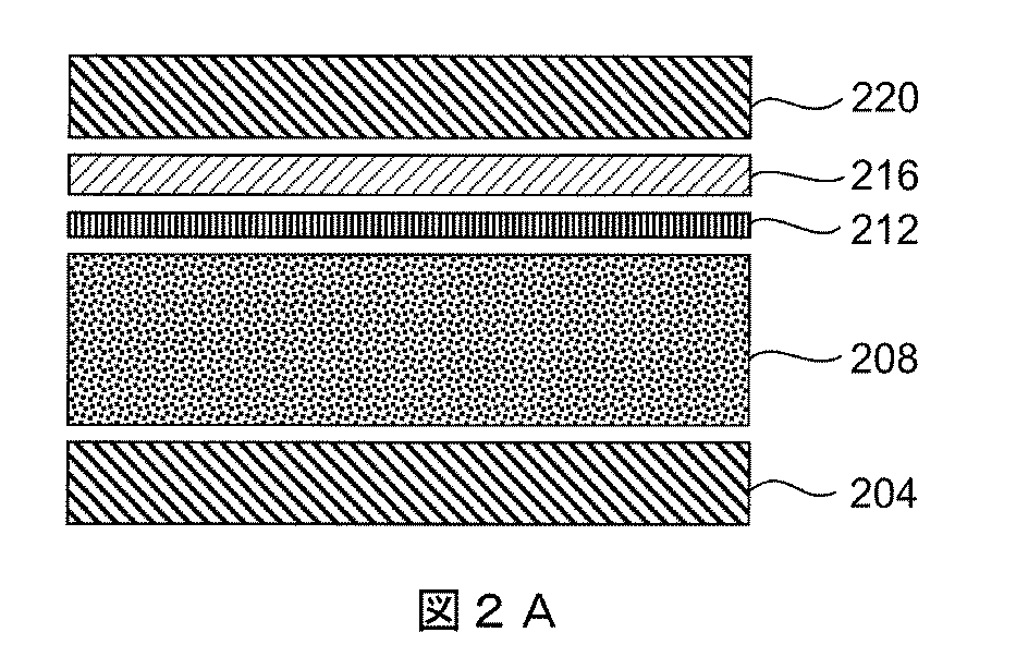
ナイロンナノ繊維層の概算保持能は、単層膜のカバレッジ1%の場合に約77%、単層膜のカバレッジ5%の場合に69%である。ナノ繊維層に対する圧力降下を0.1psiと小さく抑えるための流量制御が現実問題として困難であるがゆえに、これらの結果にはばらつきがあった。 The approximate retention capacity of the nylon nanofiber layer is about 77% for a single layer membrane coverage of 1% and 69% for a single layer membrane coverage of 5%. These results varied because the flow control to keep the pressure drop to the nanofiber layer as small as 0.1 psi was difficult as a real problem.
これらの結果には再現性があり、ナイロンナノ繊維を有する5nm規定の非対称UPE微孔膜のほうが、非対称微孔UPE膜単独よりも粒子保持能が高く、圧力降下が少ない(約13パーセント少ない)ことを示している。5nm規定の非対称UPE膜と0.2ミクロンの微孔ナイロン膜0.2とを組み合わせると、UPE微孔膜単独またはナイロンナノ繊維を有する5nm規定の非対称UPE微孔膜のいずれと比較しても保持能は改善されるが圧力降下が大きく(約13パーセント大きく)なった。 These results are reproducible and the 5 nm defined asymmetric UPE microporous membrane with nylon nanofibers has higher particle retention and lower pressure drop (about 13 percent less) than the asymmetric microporous UPE membrane alone. It is shown that. Combining a 5 nm defined asymmetric UPE membrane with a 0.2 micron microporous nylon membrane 0.2 compared to either a UPE microporous membrane alone or a 5 nm defined asymmetric UPE microporous membrane with nylon nanofibers. The retention was improved but the pressure drop was large (about 13 percent greater).
実施例2
この実施例は、界面活性剤の存在下、10%単層膜(ML)粒子カバレッジ、20%単層膜粒子カバレッジ、30%ML粒子カバレッジでのフィルタ部材クーポン試料上の25ナノメートルの蛍光粒子保持能ならびに、ポリアミドナノ繊維層、さまざまなサイズ規定のUPE微孔膜、ポリアミドナノ繊維層と微孔UPE膜との組み合わせのバブルポイントおよびイソプロピルアルコール流下時間を比較する。
Example 2
This example shows 25 nanometer fluorescent particles on a filter member coupon sample with 10% monolayer (ML) particle coverage, 20% monolayer membrane coverage, 30% ML particle coverage in the presence of surfactant. The retention capacity and the bubble point and isopropyl alcohol flow time of the polyamide nanofiber layer, various size-defined UPE microporous membranes, the combination of polyamide nanofiber layer and microporous UPE membrane are compared.
微孔UPE膜クーポンは粒子保持能試験に単独で、あるいは、フィルタ部材クーポンを作るためにポリアミドナノ繊維層と組み合わせての試料。Entegris(Chaska,MN)から微孔UPE膜を得た。この実施例で評価したUPE微孔膜試料として、0.01ミクロン規定(3M(商標)HFE−7200中でのバブルポイント70psi〜83psi)、0.02ミクロン規定(3M(商標)HFE−7200中でのバブルポイント55psi〜64psi)、0.03ミクロン規定(IPA中でのバブルポイント68psi〜83psi)、0.05ミクロン規定(IPA中でのバブルポイント50psi〜63psi)UPE膜があげられる。Finetexによってナノ繊維層を作製し、これはポリアミドであった。微孔膜クーポン試料は、90ミリメートルのディスクであった。Duke Scientificから製品番号「G25」で得られる約25ナノメートルの蛍光PSLビーズを使用した。粒子保持能試験のために、0.27ppmのPSLビーズを0.3%ドデシル硫酸ナトリウム(SDS)界面活性剤中に含有し、合計容量30mLの溶液で、膜試料に3回負荷をかけて、10%MLカバレッジを達成した。界面活性剤を使用すると、ナイロン材料の非ふるい作用が最小限になり、粒子保持能試験でのふるい条件または本質的にふるい条件が得られる。この試験スタンドを図6に示す。試験圧力は0.04MPa/0.10MPa(0.01ミクロンUPE)とした。これらの試験の結果を図3、図4、図5に示す。
The microporous UPE membrane coupon is a sample for particle retention test alone or in combination with a polyamide nanofiber layer to make a filter member coupon. Microporous UPE membranes were obtained from Entegris (Chashka, MN). As UPE microporous membrane samples evaluated in this example, 0.01 micron prescribed (
これらの試験の結果から、UPE0.01ミクロンの微孔膜と比較すると、0.01ミクロンのUPEとポリアミドナノ繊維との組み合わせで、流動損失が2.2%増、界面活性剤の存在下では、被験液体が30%MLで保持能14%増、20%MLで保持能8.3%増、10%MLで保持能2.2%増につながることがわかる。 From the results of these tests, the flow loss increased by 2.2% with the combination of 0.01 micron UPE and polyamide nanofibers compared to UPE 0.01 micron microporous membrane, and in the presence of surfactant It can be seen that when the test liquid is 30% ML, the retention capacity is increased by 14%, 20% ML is increased by retention capacity by 8.3%, and 10% ML is increased by retention capacity by 2.2%.
これらの試験の結果から、UPE0.02ミクロンの微孔膜と比較すると、0.02ミクロンのUPEとポリアミドナノ繊維との組み合わせで、流動損失が1.7%減、界面活性剤の存在下では、被験液体が30%MLで保持能13.6%増、20%MLで保持能3.6%増、1%MLで保持能1.4%減につながることがわかる。 From the results of these tests, the flow loss is reduced by 1.7% in the combination of 0.02 micron UPE and polyamide nanofibers compared to UPE 0.02 micron microporous membrane, in the presence of surfactant. It can be seen that, when the test liquid is 30% ML, the retention capacity is increased by 13.6%, the retention capacity is increased by 3.6% by 20% ML, and the retention capacity is decreased by 1.4% by 1% ML.
これらの試験の結果から、UPE0.03ミクロンの微孔膜と比較すると、0.03ミクロンのUPEとポリアミドナノ繊維との組み合わせで、流動損失が4.1%増、界面活性剤の存在下では、被験液体が30%MLで保持能23.7%増、20%MLで保持能3.9%増、10%MLで保持能0%増につながることがわかる。 From the results of these tests, the flow loss increased by 4.1% with the combination of 0.03 micron UPE and polyamide nanofibers compared with the UPE 0.03 micron microporous membrane. It can be seen that, when the test liquid is 30% ML, the retention capacity is increased by 23.7%, the retention capacity is increased by 20% ML by 3.9%, and the retention capacity is increased by 10% ML by 0%.
これらの試験の結果から、UPE0.05ミクロンの微孔膜と比較すると、0.05ミクロンのUPEとポリアミドナノ繊維との組み合わせで、流動損失が2.7%増、界面活性剤の存在下では、被験液体が30%MLで保持能16.2%増、20%MLで保持能6.2%増、10%MLで保持能1.6%減につながることがわかる。 From the results of these tests, the flow loss increased by 2.7% with the combination of 0.05 micron UPE and polyamide nanofibers compared to UPE 0.05 micron microporous membrane, and in the presence of surfactant. It can be seen that, when the test liquid is 30% ML, the retention capacity is increased by 16.2%, the retention capacity is increased by 6.2% by 20% ML, and the retention capacity is decreased by 1.6% by 10% ML.
表2の結果からわかるように、ナノ繊維層を用いると、界面活性剤の存在下、被験液体中で、フィルタ部材の被験粒子単層膜被覆率を高めつつ、微孔膜に比して、全体としての粒子保持能が大きくなる。これらの試験の結果から、ナノ繊維層を有する試料クーポンでの粒子吸着量が増すと、すなわち10%ML、20%MLなど、フィルタ部材の全体としての吸着能力への寄与率も大きくなる。 As can be seen from the results in Table 2, when using the nanofiber layer, in the test liquid in the presence of the surfactant, while increasing the test particle monolayer film coverage of the filter member, compared to the microporous membrane, The overall particle retention capacity is increased. From the results of these tests, when the particle adsorption amount in the sample coupon having the nanofiber layer is increased, that is, the contribution rate to the entire adsorption capacity of the filter member such as 10% ML and 20% ML is increased.
複合膜またはフィルタ部材のPSL保持能を図3に示す。このフィルタ部材の30%単層膜保持能を図4に示し、このフィルタ部材のIPA流下時間を図5に示す。 FIG. 3 shows the PSL retention capacity of the composite membrane or filter member. FIG. 4 shows the 30% monolayer film holding ability of this filter member, and FIG. 5 shows the IPA flow time of this filter member.
IPA流下時間試験の結果から、微孔膜単独と微孔膜およびナノ繊維層の組み合わせとの流下時間の差が約±4%異なることがわかる。30%MLカバレッジでの粒子保持能について、微孔膜およびナノ繊維の組み合わせでの保持能が、UPE膜単独より14%〜24%高くなる。膜のPSL粒子カバレッジが10%MLから30%MLまで徐々に直線的に増すにつれて、UPE微孔膜単独の保持性能が小さくなる。逆に、(UPE+ナノ繊維)の組み合わせによる保持能はそれほど低下しない。 From the results of the IPA flow time test, it can be seen that the flow time difference between the microporous membrane alone and the combination of the microporous membrane and the nanofiber layer differs by about ± 4%. For particle retention at 30% ML coverage, the retention in the combination of microporous membrane and nanofiber is 14% to 24% higher than the UPE membrane alone. As the PSL particle coverage of the membrane gradually increases linearly from 10% ML to 30% ML, the retention performance of the UPE microporous membrane alone decreases. On the contrary, the retention ability by the combination of (UPE + nanofiber) does not decrease so much.
2つの試料(UPEおよびUPE+ナノ繊維)の保持性能の差は、単層膜のカバレッジが大きくなるにつれて大きくなる。これは、ナノ繊維と微孔膜との組み合わせであれば、UPE微孔膜単独よりも経時的な保持能が高いことを示している。 The difference in retention performance between the two samples (UPE and UPE + nanofibers) increases as the coverage of the monolayer increases. This indicates that the combination of nanofibers and microporous membrane has higher retention capacity over time than the UPE microporous membrane alone.
実施例3
この実施例は、非対称微孔UPE膜のみまたはナイロン不織支持体上のナイロンナノ繊維と同一の非対称微孔UPE膜との組み合わせのいずれかで作製した3つの4インチのOptimizer(登録商標)D規定のフィルタカートリッジ装置で圧力降下、粒子離脱試験、粒子保持能を測定するものである。Optimizer(登録商標)Dフィルタは、Entegris(Chaska, MN)製である。この実施例用に作製した当該フィルタカートリッジ装置を、圧力降下試験、粒子保持能試験、粒子離脱試験で評価した。あるフィルタカートリッジ装置(Optimizer(登録商標)D Asy5nm)をEntegrisの5ナノメートルの非対称UPE膜で用意したが、他の2つの装置(Optimizer(登録商標)D Asy5nm SP)については5nmの非対称UPE膜と0.2um規定のナイロンナノ繊維の層(NNF1+UPEまたはNNF2+UPEと略記)で用意した。
Example 3
This example shows three 4 inch Optimizer® D made with either asymmetric microporous UPE membrane alone or a combination of nylon nanofibers on nylon nonwoven support and the same asymmetric microporous UPE membrane. The pressure drop, particle detachment test, and particle retention ability are measured with a specified filter cartridge device. The Optimizer® D filter is manufactured by Entegris (Chashka, MN). The filter cartridge device produced for this example was evaluated by a pressure drop test, a particle retention test, and a particle detachment test. One filter cartridge device (Optimizer (R) D Asy5nm) was prepared with
フィルタカートリッジ装置についての別の情報を表3にまとめておく。 Other information about the filter cartridge device is summarized in Table 3.
Finetexから得たナイロンナノ繊維を不織ナイロン支持体に適用して、フィルタ装置を作製した。ナノ繊維層を5ナノメートルの非対称UPE膜の開放側に向けて配置し、別のポリエチレン裏打ち層を得た。ナイロン不織物、ナイロンナノ繊維、5ナノメートルの非対称UPE微孔膜、ポリエチレン裏材を含む組み合わせをエンドキャップで結合し、試験用にプロトタイプのフィルタカートリッジ装置を形成した。Entegris, Inc.から非対称の5nm微孔膜を入手した。これは、3M(商標)HFE−7200でのバブルポイント95psi〜110psiを特徴とするものである。 Nylon nanofibers obtained from Finetex were applied to a nonwoven nylon support to make a filter device. The nanofiber layer was placed toward the open side of the 5 nanometer asymmetric UPE membrane to obtain another polyethylene backing layer. A combination including nylon nonwoven, nylon nanofiber, 5 nanometer asymmetric UPE microporous membrane, polyethylene backing was joined with an end cap to form a prototype filter cartridge device for testing. Entegris, Inc. Obtained an asymmetric 5 nm microporous membrane. This is characterized by a bubble point of 95 psi to 110 psi on 3M ™ HFE-7200.
ナノ繊維層は、直径約60ナノメートル〜約150ナノメートルの繊維を有していた。ナノ繊維層の厚さは約5ミクロン、IPAバブルポイントで判断したナノ繊維層の規定サイズは0.2ミクロンであった。 The nanofiber layer had fibers with a diameter of about 60 nanometers to about 150 nanometers. The thickness of the nanofiber layer was about 5 microns, and the defined size of the nanofiber layer as judged by the IPA bubble point was 0.2 microns.
5ナノメートルの非対称UPE微孔膜だけを有するフィルタ装置では、ナイロンナノ繊維および非対称の5ナノメートルのUPE微孔膜で作製した装置での場合よりも圧力降下が大きかった。 The filter device with only a 5 nanometer asymmetric UPE microporous membrane had a greater pressure drop than in a device made with nylon nanofibers and an asymmetric 5 nanometer UPE microporous membrane.
使用したG25粒子は、25ナノメートルでの粒子の公称直径を一覧にしたDuke Scientific(Thermo Fisher Scientific Inc.,(Waltham, MA))によって流通しているものであったが、実験室での測定では、Brookhaven Instrument Corporation製の動的光散乱機器、モデルBI−2005Mで約21ナノメートル〜24ナノメートルの粒子径が示される。 The G25 particles used were distributed by Duke Scientific (Thermo Fisher Scientific Inc., (Waltham, Mass.)), Which lists the nominal diameter of the particles at 25 nanometers, but measured in the laboratory. Then, a dynamic light scattering device, model BI-2005M, manufactured by Brookhaven Instrument Corporation, shows a particle size of about 21 nanometers to 24 nanometers.
試験の前に、3つのフィルタをまずはイソプロピルアルコール(IPA)で湿らせ、続いてDI水で約30分間フラッシュした。 Prior to testing, the three filters were first moistened with isopropyl alcohol (IPA) and then flushed with DI water for about 30 minutes.
この実施例の3つのフィルタ装置を、図6に示すような単一のバイパステストスタンドで一緒に試験した。脱イオン(DI)水中での粒子負荷時には1リットル/分の流量を用いた。次に、DI水中のG25蛍光粒子ならびに、非ふるい作用を除外するための界面活性剤(Triton X−100)を添加したものでフィルタに負荷をかけた。界面活性剤については、圧力容器を用いて、臨界ミセル濃度(CMC)より上の0.1%界面活性剤濃度を目標とする一定流量で、フィルタの上流に注入した。界面活性剤濃度がCMCの上に保たれるようにするために、表面張力計を用いて流体の表面張力を監視した。30ダインの値が0.1%濃度に相関している。 The three filter devices of this example were tested together in a single bypass test stand as shown in FIG. A flow rate of 1 liter / min was used during particle loading in deionized (DI) water. Next, the filter was loaded with G25 fluorescent particles in DI water and a surfactant (Triton X-100) added to exclude non-sieving action. For the surfactant, a pressure vessel was used to inject upstream of the filter at a constant flow rate targeting a 0.1% surfactant concentration above the critical micelle concentration (CMC). The surface tension of the fluid was monitored using a surface tensiometer in order to keep the surfactant concentration above the CMC. A value of 30 dynes correlates to 0.1% concentration.
界面活性剤を加えると、達成可能な流量が約0.8LPMに減少した。この流量を用いて、界面活性剤とともにすべてのフィルタの保持能を試験した。G25蛍光粒子を既知の濃度でフィルタの上流に45分間注入した。5分ごとにフィルタの上流と下流の両方で試料を回収し、Hitachi F−7000 FL蛍光分光計で測定した。 The addition of surfactant reduced the achievable flow rate to about 0.8 LPM. This flow rate was used to test the retention of all filters along with the surfactant. G25 fluorescent particles were injected at a known concentration upstream of the filter for 45 minutes. Samples were collected every 5 minutes both upstream and downstream of the filter and measured on a Hitachi F-7000 FL fluorescence spectrometer.
すべての装置に対して同時に一定流量のG25蛍光粒子で負荷をかけた。各装置からの上流および下流の溶液の蛍光シグナルを測定した。 All devices were simultaneously loaded with a constant flow of G25 fluorescent particles. The fluorescence signal of the upstream and downstream solutions from each device was measured.
この実施例のために用意したすべての試験フィルタ装置で、静的およびパルス脱落下、同様の粒子離脱性能が認められたことから、ナノ繊維の繊維がプロセスの液体流に放出すなわち離脱していないことがわかる。すべての装置で、低めのpH6ならびに中性のpH7の条件にて、DI水中にてG25蛍光粒子の良好かつ同程度の保持能が認められた。pH8で試験した場合に、すべての装置でG25蛍光粒子の保持能が低下することが観察されたことから、高めのpH条件では非ふるい作用が落ちることがわかる。
All test filter devices prepared for this example showed static and pulse drop-off, similar particle detachment performance, so the nanofiber fibers were not released or detached into the process liquid stream. I understand that. All devices showed good and comparable retention of G25 fluorescent particles in DI water at
上流の溶液に界面活性剤を加えると、すべてのフィルタのG25粒子保持能が低下し、これによって非ふるい保持能作用も低下した(保持能は主にふるいによる)ことから、DI水中におけるサイズ25nmの粒子の保持能は、かなりの部分が非ふるい作用によるものであることが示唆される。界面活性剤を加えると、非対称の5ナノメートルのUPE微孔膜だけを用いたフィルタと、非対称の5ナノメートルのUPE微孔膜とナイロンナノ繊維層の両方を用いた装置の粒子保持能を区別できる。低めのpH6および中性のpH7の条件では、非対称の5ナノメートルのUPE微孔膜とナイロンナノ繊維膜とを有する装置の粒子保持能が、非対称の5ナノメートルのUPE微孔膜だけを用いた装置の場合よりもわずかによいことが、一貫して観察される。これらの結果から、別のナイロンナノ繊維層を有する装置のほうが非ふるい作用が高いことが示唆される。
Adding a surfactant to the upstream solution reduced the G25 particle retention capacity of all filters, which also reduced the non-sieving retention effect (mainly due to sieving), so
しかしながら、非ふるい作用が低下する高めのpH8では、粒子保持能の区別がはっきりしない。ナイロンナノ繊維を有する装置で最初は高めの保持能が観察されるが、試験の最後には保持能が低下する。理論に拘泥されるものではないが、観察された保持能は、フィルタが複数回にわたって使用され、前の試験から影響を受けた結果の可能性がある。本発明者らは、各試験を新しいフィルタで実施すれば、異なるpHおよび界面活性剤条件で、保持能をさらに区別しやすいのではないかと考えている。
However, at
DI水を各フィルタカートリッジ装置に一連の流量で流し、フィルタでの圧力降下を観察して、フィルタの圧力降下を測定した。UPE微孔膜だけを用いたフィルタは、5nmのUPE膜と0.2ミクロン規定のナイロンナノ繊維層とを用いたフィルタよりも圧力降下が大きかった。図7のグラフを参照すると、約650ml/分の流れで、ナノ繊維とUPE微孔膜とを用いたフィルタの圧力降下が、UPE微孔膜のみのフィルタで測定した圧力降下よりも約11%以上(すなわち12%)少ない。 DI water was passed through each filter cartridge device at a series of flow rates, and the pressure drop across the filter was observed to measure the pressure drop across the filter. The filter using only the UPE microporous membrane had a greater pressure drop than the filter using a 5 nm UPE membrane and a 0.2 micron nylon nanofiber layer. Referring to the graph of FIG. 7, at a flow of about 650 ml / min, the pressure drop of the filter using nanofibers and the UPE microporous membrane is about 11% higher than the pressure drop measured with the filter of the UPE microporous membrane only. Over (ie 12%) less.
もうひとつの試験の組では、ナノ繊維およびUPE微孔膜を用いたフィルタと、UPE微孔膜だけを用いたフィルタの圧力降下を、プロピレングリコールモノメチルエーテル(PGME)のような有機液体を用いて測定した。図8に示す結果から、ナノ繊維およびUPE膜を用いる装置では、UPE膜単独の装置よりも圧力降下が小さいことがわかる。PGMEについてこのグラフを参照すると、約0.5リットル/分の流量で、ナノ繊維およびUPEを用いたフィルタの圧力降下は、UPE膜のみを用いたフィルタで測定した圧力降下よりも約21%以上(22%など)低い。 In another set of tests, the pressure drop between a filter using nanofibers and a UPE microporous membrane and a filter using only a UPE microporous membrane was measured using an organic liquid such as propylene glycol monomethyl ether (PGME). It was measured. From the results shown in FIG. 8, it can be seen that the pressure drop is smaller in the apparatus using the nanofiber and the UPE film than in the apparatus using only the UPE film. Referring to this graph for PGME, at a flow rate of about 0.5 liters / minute, the pressure drop of the filter using nanofibers and UPE is about 21% more than the pressure drop measured with the filter using only the UPE membrane. (22% etc.) Low.
DI水を1リットル/分でフィルタに流し、フィルタの下流で光学粒子カウンタ(OPC)を用いて粒子数を測定して、3つのフィルタカートリッジ装置の粒子離脱性能を試験した。各フィルタを一定の圧力で少なくとも1時間試験し、系の圧力を1時間にわたって30秒ごとにスパイクするパルス条件下でフィルタに負荷をかけた。 DI water was allowed to flow through the filter at 1 liter / minute and the particle count was measured using an optical particle counter (OPC) downstream of the filter to test the particle detachment performance of the three filter cartridge devices. Each filter was tested at a constant pressure for at least 1 hour, and the filter was loaded under pulsed conditions that spike the system pressure every 30 seconds for 1 hour.
図9、図10、図11の結果から、3つのフィルタカートリッジ装置すべてがその離脱およびパルス離脱性能で同程度であることがわかり、ナノ繊維がフィルタの粒子離脱を増すわけではないことが示される。 The results of FIGS. 9, 10, and 11 show that all three filter cartridge devices are comparable in their detachment and pulse detachment performance, indicating that the nanofibers do not increase the particle detachment of the filter. .
フィルタカートリッジ装置に、DI水中のG25蛍光粒子で負荷をかけた。フィルタの上流に、粒子を45分間注入し、粒子分析用の試料をフィルタの上流と下流で5分ごとに回収した。次に、試料を蛍光分光計で測定した。45分間の粒子注入の結果から、どのフィルタ(NNF1+UPE、NNF2+UPEおよびUPEのみ)も界面活性剤なしでpH6(図10)およびpH7(図9)での粒子保持能が極めて良好かつ同程度であることがわかる。pH8で界面活性剤を使用しない(図11)と、すべてのフィルタの保持能が低下するが、NNF1+UPEおよびNNF2+UPEフィルタ部材はUPEのみのフィルタより保持能が大きいことから、これらの高pH条件での非ふるい条件下ですら、NNF1+UPEおよびNNF2+UPEのフィルタ部材では比較的大きなサイズの規定ナイロンナノ繊維層を用いた場合にすらもふるい保持能が良好であることが示される。図10では、ポイントが本質的に互いに重なるため、わかりやすくするためにトレンドラインを割愛してある。 The filter cartridge device was loaded with G25 fluorescent particles in DI water. Particles were injected upstream of the filter for 45 minutes and samples for particle analysis were collected every 5 minutes upstream and downstream of the filter. The sample was then measured with a fluorescence spectrometer. From the results of 45 minutes of particle injection, all filters (NNF1 + UPE, NNF2 + UPE and UPE only) have very good and comparable particle retention capacity at pH 6 (FIG. 10) and pH 7 (FIG. 9) without surfactant. I understand. If no surfactant is used at pH 8 (FIG. 11), the retention capacity of all filters is reduced, but NNF1 + UPE and NNF2 + UPE filter members have a greater retention capacity than UPE-only filters, so under these high pH conditions Even under non-sieving conditions, NNF1 + UPE and NNF2 + UPE filter members are shown to have good sieving retention when using a relatively large sized nylon nanofiber layer. In FIG. 10, since the points essentially overlap each other, the trend line is omitted for the sake of clarity.
再度、G25蛍光粒子を用いるが、今度は非ふるい作用をなくすために界面活性剤をプロセス流に加えてフィルタを試験した。界面活性剤を一定速度で注入し、フィルタで0.1%濃度を達成した。この濃度はCMCより上であった。 Again, G25 fluorescent particles were used, but this time the surfactant was added to the process stream to eliminate non-sieving effects and the filter was tested. Surfactant was injected at a constant rate and a 0.1% concentration was achieved with the filter. This concentration was above the CMC.
表面張力計で測定して下流のプロセス溶液が安定した界面活性剤濃度に達したら、G25粒子を既知の濃度でフィルタの上流に注入した。5分ごとにフィルタの上流と下流で試料を回収し、蛍光分光計で測定した。界面活性剤を用いて粒子を45分間注入した結果(図12および図13)から、すべてのフィルタで保持能が低下したことがわかる。理論に拘泥されるものではないが、これらの結果は、DI水だけで保持能が高くなるのは、大部分が非ふるい作用によるものであることを示唆している。しかしながら、低めのpH6および中性のpH7では、フィルタ部材NNF1+UPEおよびNNF2+UPEにUPEおよびNylonナノ繊維膜を併用すると、UPE膜だけのフィルタよりも保持能が改善される。
When the downstream process solution reached a stable surfactant concentration as measured by a surface tension meter, G25 particles were injected upstream of the filter at a known concentration. Samples were collected upstream and downstream of the filter every 5 minutes and measured with a fluorescence spectrometer. From the results of injecting particles with a surfactant for 45 minutes (FIGS. 12 and 13), it can be seen that the retention ability of all the filters was lowered. Without being bound by theory, these results suggest that the increased retention with DI water alone is largely due to non-sieving action. However, at
実施例4
表4にまとめたこの実施例の結果から、異なる支持層上の直径の異なるナノ繊維の透気度、流下時間および保持能がわかる。
Example 4
The results of this example summarized in Table 4 show the air permeability, flow time and retention capacity of nanofibers with different diameters on different support layers.
この実施例は、異なる支持体(不織物、一つの例では微孔膜)上のナノ繊維の直径が有し得る、透気度および液体流下時間に対する作用を測定するものである。準備した試料では、不織支持層のほうが、ナノ繊維層よりもこれらの実施例でのサイズ等級がかなり大きい。 This example measures the effect of nanofiber diameter on different supports (non-woven, in one example microporous membrane) on air permeability and liquid flow time. In the prepared samples, the nonwoven support layer has a much larger size rating in these examples than the nanofiber layer.
ナノ繊維の直径は、約50ナノメートル〜約1600ナノメートルの範囲であった。以下の図では、支持層(PET不織物、ポリプロピレン(PP)不織物、PA不織物)、ナノ繊維(ポリアミドナノ繊維(PA NF)、PESナノ繊維)、微孔膜(UPE)のさまざまな組み合わせ、さまざまな層の厚さ、層の順序、表中での試料の表示(NF−1、NF−2など)を図14にあげておく。 The nanofiber diameters ranged from about 50 nanometers to about 1600 nanometers. In the figure below, various combinations of support layer (PET nonwoven, polypropylene (PP) nonwoven, PA nonwoven), nanofiber (polyamide nanofiber (PANF), PES nanofiber), microporous membrane (UPE) FIG. 14 shows various layer thicknesses, layer orders, and sample indications (NF-1, NF-2, etc.) in the table.
この試験の結果から、異なる支持体(不織物、一つの例では微孔膜)上のナノ繊維の直径が有し得る、透気度および液体流下時間に対する作用が認められた。不織支持層のほうがナノ繊維層よりもこれらの実施例でのサイズ等級がかなり大きい。さまざまな試料が、ナノ繊維径の範囲が約150ナノメートル未満または平均ナノ繊維径が300nm未満、たとえば200ナノメートルまたは150ナノメートルの試料の場合、支持体上のナノ繊維の透気度が1.4sec/200ミリリットルを超え、これらはpH6で0.055ミクロンの粒子に対して約90%PSL保持能を超え、さらに高い保持率を達成可能であることを示している。NF層の厚さが5〜20ミクロンの試料NF−1、NF−4、NF−5、NF−6は、透気度が1.75sec/200ml〜24.1sec/200mlの範囲であり、0.1ミクロンの粒子やこれより大きな粒子に対してPSL粒子保持能が88%〜100%である。
From the results of this test, the effect on the air permeability and liquid flow time that the diameter of the nanofibers on different supports (nonwoven, in one example microporous membrane) can have was observed. The nonwoven support layer has a much larger size rating in these examples than the nanofiber layer. If the various samples are samples having a nanofiber diameter range of less than about 150 nanometers or an average nanofiber diameter of less than 300 nm, such as 200 nanometers or 150 nanometers, the nanofiber permeability on the support is 1 > 4 sec / 200 milliliters, which exceeds about 90% PSL retention for 0.055 micron particles at
実施例5
この実施例は、ナノ繊維の1つ以上の層、微孔膜、不織多孔質支持体、1つ以上の別の支持層またはドレナージ層を含むフィルタ部材を示すものである。
Example 5
This example shows a filter member comprising one or more layers of nanofibers, a microporous membrane, a non-woven porous support, one or more other support layers or drainage layers.
バブルポイント、プリウェットフロー、圧力降下、粒子保持能試験用に、6つの修飾されたImpact(登録商標)2 V2スタイル装置を入手した。3つの装置はEntegrisの3nm非対称UPE膜を有する形で作られ、他の3つの装置はEntegrisの5nm非対称UPE膜を有する形で作られた。UPE膜は、Yenら、2005年12月21日にファイルされた、特許協力条約に基づく国際公開第2006/069307号パンフレット(その内容全体を参照により本出願に援用する)に開示された方法で作製される非対称膜である。UPE微孔膜を有するImpact(登録商標)2フィルタは、Entegris Inc.,(Billerica, MA)から入手可能である。
Six modified
この実施例は、0.2μmのNylonナノ繊維からなる別の層を用いる場合と用いない場合とで、Impact(登録商標)2装置の粒子保持能を示すものである。各々3nmおよび5nm規定のUPE膜に対する3つの装置の組の中で、1つの装置をUPE膜だけを用いて作製し、他の2つの装置を、UPE膜と、0.2μm規定のNylonナノ繊維からなる別の1つまたは2つの層とを用いて作製した。
This example shows the particle retention capacity of the
この実施例では、すべての保持能試験(異なるpH6〜8、異なる流量)を同一の装置で実施した。本発明者らは、それぞれの試験を新しい装置で実施すれば、異なるpHおよび流量で、さらに保持能を区別しやすくなるであろうと考えている。 In this example, all retention tests (different pH 6-8, different flow rates) were performed on the same device. The inventors believe that if each test is performed on a new device, it will be easier to distinguish retention at different pH and flow rates.
1つ以上のNylonナノ繊維層は、厚さが約2ミクロン、平均サイズ等級0.2ミクロンまたは約0.2ミクロンであった。ナノ繊維の直径は、100ナノメートル〜150ナノメートルまたは約100ナノメートル〜約150ナノメートルの範囲であった。ナノ繊維層のサイズ等級については、微孔膜で用いたものと同一のバブルポイント技術を用いて判断した。ナノ繊維層におけるナノ繊維の直径の平均を、繊維の無作為試料のSEMによって測定し、値を平均した。 The one or more Nylon nanofiber layers had a thickness of about 2 microns and an average size rating of 0.2 microns or about 0.2 microns. Nanofiber diameters ranged from 100 nanometers to 150 nanometers or from about 100 nanometers to about 150 nanometers. The size grade of the nanofiber layer was determined using the same bubble point technique used for the microporous membrane. The average nanofiber diameter in the nanofiber layer was measured by SEM of a random sample of fibers and the values averaged.
旭化成から入手した不織スパンボンド多孔質支持体を使用し、この不織多孔質支持体の2つのバージョンを、5040および5030と表示し、坪量はそれぞれ40g/m2または30g/m2である。ナイロンナノ繊維をこの不織多孔質支持体上に成膜した。Delstar、Delewareから入手可能なポリエチレン製のポリマーネットを、外側のドレナージ層として使用した。表6では、このネットを「PEネット」と略記する。 Use was obtained from Asahi nonwoven spunbond porous support, the two versions of the non-woven porous support, indicated as 5040 and 5030, the basis weight at each 40 g / m 2 or 30 g / m 2 is there. Nylon nanofibers were deposited on this nonwoven porous support. A polyethylene polymer net available from Delstar, Delwere was used as the outer drainage layer. In Table 6, this net is abbreviated as “PE net”.
表5または表6の試料フィルタについて、0.34MPaで60秒間漏洩試験した。試料を5分間低周波洗浄した。装置の可視的なIPAバブルポイント(BP)を装置ごとに測定した。各試料を水でフラッシュした後、装置ごとに水流量試験を実施した。次に、これらの装置を以下のようにして洗浄した。1回目の酸洗浄(60%IPA、0.1NのHClで3時間);2リットル/分で水を用いて5分間酸抽出;2回目の酸洗浄(60%IPA、0.1NのHClで12時間);2リットル/分で水を用いて5分間酸抽出。ユニットを70℃で乾燥させた。 The sample filter of Table 5 or Table 6 was subjected to a leak test at 0.34 MPa for 60 seconds. Samples were low frequency washed for 5 minutes. The visible IPA bubble point (BP) of the device was measured for each device. After each sample was flushed with water, a water flow test was performed for each device. Next, these apparatuses were cleaned as follows. First acid wash (60% IPA, 0.1N HCl for 3 hours); acid extraction with water at 2 liters / min for 5 minutes; second acid wash (60% IPA, 0.1N HCl with 12 hours); acid extraction with water at 2 liters / minute for 5 minutes. The unit was dried at 70 ° C.
試験の前に、装置を約250ミリリットルのイソプロピルアルコール(IPA)でフラッシュし、微孔膜を十分に湿らせた。装置を完全に脱気した後、DI水で30分〜60分間フラッシュした。 Prior to testing, the device was flushed with about 250 milliliters of isopropyl alcohol (IPA) to fully wet the microporous membrane. The apparatus was completely degassed and then flushed with DI water for 30-60 minutes.
3ナノメートルの非対称微孔膜を含む1つ以上のナノ繊維層を有するフィルタ部材試料の場合のプリウェット水の流量についての表6に示す結果から、圧力0.06MPaでのリットル/分単位の流量が、2層のナノ繊維(0.06MPaで0.25リットル/分)でほぼ同一(0%)であり、1層のナノ繊維(0.06MPaで0.022リットル/分)では流量が約12%少ないことがわかる。5ナノメートルの非対称微孔膜を含む1つ以上のナノ繊維層を有するフィルタ部材を用いた場合のこの実施例の結果から、圧力0.06MPaでのリットル/分の流量が、2層のナノ繊維(0.06MPaで0.38リットル/分)では約7%少なく、1層のナノ繊維(0.06MPaで0.41リットル/分)では流量がほぼ同一(0%)であることがわかる。 From the results shown in Table 6 for the flow rate of pre-wet water in the case of a filter member sample having one or more nanofiber layers comprising a 3 nanometer asymmetric microporous membrane, the results are shown in liters per minute at a pressure of 0.06 MPa. The flow rate is almost the same (0%) for two layers of nanofibers (0.25 liter / min at 0.06 MPa), and the flow rate is one layer of nanofibers (0.022 liter / min at 0.06 MPa). It can be seen that there is about 12% less. From the results of this example when using a filter member having one or more nanofiber layers comprising a 5 nanometer asymmetric microporous membrane, a flow rate in liters per minute at a pressure of 0.06 MPa is shown for two layers of nanofibers. The fiber (0.38 liter / min at 0.06 MPa) is about 7% less, and the flow rate is almost the same (0%) with one layer of nanofiber (0.41 liter / min at 0.06 MPa). .
一連の流量で各装置にDI水を流し、装置での圧力降下を観察することで、装置の圧力降下を測定した。図15および図16に、3nmおよび5nmの装置の圧力降下をまとめておく。3nmまたは5nmのUPE膜を用いた装置では、1層または2層のナノ繊維を有する装置の圧力降下が、0ml/分〜約220ml/分の流量範囲でほぼ同一または実質的に同一であった。0ミリリットル/分〜約220ミリリットル/分の流量範囲では、3nmの非対称微孔UPE膜のみを用いた装置の場合に約220ml/分で約6.8psiの圧力降下が認められたのに対し、2層または1層のナノ繊維および3nmの非対称微孔UPE膜を用いた装置では、図15に示すように、約220ml/分でわずかに大きな圧力降下である約7.6psiおよび約7.8psi(それぞれ約12パーセントおよび15パーセント大きい)であった。0ミリリットル/分〜約220ミリリットル/分の流量範囲では、5nmの非対称微孔UPE膜のみを用いた装置の圧力降下が約220ml/分で約6.8psiであったのに対し、2層または1層のナノ繊維および5nmUPE膜を用いた装置では、図16に示すように、約220ml/分でわずかに小さな圧力降下である約6.1psiおよび約6.2psi(それぞれ約7.5パーセントおよび6パーセント小さい)であった。 The pressure drop of the device was measured by flowing DI water through each device at a series of flow rates and observing the pressure drop across the device. FIG. 15 and FIG. 16 summarize the pressure drop of the 3 nm and 5 nm devices. For devices using 3 nm or 5 nm UPE membranes, the pressure drop of the device with one or two layers of nanofibers was almost the same or substantially the same in the flow range from 0 ml / min to about 220 ml / min. . In the flow range from 0 milliliters / minute to about 220 milliliters / minute, a pressure drop of about 6.8 psi was observed at about 220 ml / minute for an apparatus using only a 3 nm asymmetric microporous UPE membrane, For devices using two-layer or single-layer nanofibers and a 3 nm asymmetric microporous UPE membrane, as shown in FIG. 15, a slightly higher pressure drop at about 220 ml / min, about 7.6 psi and about 7.8 psi (About 12 percent and 15 percent greater respectively). In the flow range from 0 ml / min to about 220 ml / min, the pressure drop of the apparatus using only the 5 nm asymmetric microporous UPE membrane was about 6.8 psi at about 220 ml / min, whereas two layers or In a device using a single layer of nanofibers and a 5 nm UPE membrane, as shown in FIG. 16, a slightly smaller pressure drop at about 220 ml / min, about 6.1 psi and about 6.2 psi (about 7.5 percent and 6 percent smaller).
図6に示す単一のバイパス試験スタンドで、すべての装置の粒子保持能を一緒に試験した。UPE膜、特に3nmUPE膜の圧力降下がゆえに、DI水を用いる場合の最大流量を0.5リットル/分(lpmまたはLPM)とした。DI水の上流ストリームに界面活性剤を注入する場合、流量をさらに落として3ナノメートル(nm)UPE装置で用いた最大流量が0.36LPMであった。0.36LPMの流量は、3nmのUPE装置すべてを試験した流量であった。比較のために、5nmのUPE装置を流量0.36LPMで試験し、流量0.5LPMでも評価した。 All devices were tested together for particle retention in a single bypass test stand shown in FIG. Due to the pressure drop of UPE membranes, especially 3 nm UPE membranes, the maximum flow rate when using DI water was 0.5 liters / minute (lpm or LPM). When injecting the surfactant into the upstream stream of DI water, the maximum flow rate used in a 3 nanometer (nm) UPE device with a further decrease in flow rate was 0.36 LPM. The flow rate of 0.36 LPM was the flow rate tested for all 3 nm UPE devices. For comparison, a 5 nm UPE device was tested at a flow rate of 0.36 LPM and evaluated at a flow rate of 0.5 LPM.
粒子保持能試験の場合、G25粒子を界面活性剤であるTriton(登録商標)−X 100と組み合わせ、非ふるい濾過作用を大幅に小さくした。約6wt%の界面活性剤ストックをタンクで別に調製し、攪拌しながら十分に溶解させた。この濃縮界面活性剤溶液は、1週間を超えても安定していることが見出された。圧力容器を用いて、臨界ミセル濃度(CMC)より上の0.1%界面活性剤濃度を目標とする一定流量で、濃縮界面活性剤溶液を装置の上流に注入した。界面活性剤濃度がCMCの上に保たれるようにするために、表面張力計を用いて流体の表面張力を監視した。0.1%濃度に相関している31ダインの値を、界面活性剤注入の5分後に測定した。粒子で負荷をかける前に、界面活性剤を注入して装置全体に少なくとも10分間安定した流れを確立し、各々の装置での上流および下流の対照試料を回収した。同様に、pHポンプを用いて必要な量の0.1%水酸化カリウムKOHまたは0.1%HCL溶液を加えて、プロセス流のpHを制御した。
In the particle retention test, G25 particles were combined with a surfactant Triton (registered trademark) -
装置の上流に、既知の濃度で30分間、G25粒子を注入した。試料フィルタ装置の上流と下流の両方で5分ごとに試料を回収し、上流および下流試料の粒子をHitachi F−7000 FL分光計で測定した。 G25 particles were injected upstream of the apparatus at a known concentration for 30 minutes. Samples were collected every 5 minutes both upstream and downstream of the sample filter device, and upstream and downstream sample particles were measured on a Hitachi F-7000 FL spectrometer.
蛍光粒子保持能試験(界面活性剤あり)。最初に、非ふるい作用を大幅に抑えるために界面活性剤をプロセス流に加えた状態で、3nmのUPE装置をG25蛍光粒子で試験した。各装置の流量:3nmのUPE、3nmのUPE+1層NF、3nmのUPE+2層NFは、0.36LPMに維持した。5分前後で下流のプロセス溶液が安定した界面活性剤濃度に達したら、粒子で負荷をかける前に各装置の上流および下流で対照試料を回収した。次に、G25粒子を既知の濃度で30分間装置の上流に注入した。装置の上流および下流で5分ごとに試料を回収し、蛍光分光計で測定した。 Fluorescent particle retention ability test (with surfactant). Initially, a 3 nm UPE apparatus was tested with G25 fluorescent particles with surfactant added to the process stream to significantly reduce non-sieving effects. Flow rate of each device: 3 nm UPE, 3 nm UPE + 1 layer NF, 3 nm UPE + 2 layer NF were maintained at 0.36 LPM. When the downstream process solution reached a stable surfactant concentration around 5 minutes, control samples were collected upstream and downstream of each device prior to loading with particles. The G25 particles were then injected upstream of the device at a known concentration for 30 minutes. Samples were collected every 5 minutes upstream and downstream of the instrument and measured with a fluorescence spectrometer.
図17、図18、図19はそれぞれ、中性(pH約6.5)、低pH4.0、高pH8.5の条件で試験した3nmのUPE装置の粒子保持能データである。低pHおよび中性pH(図17および図18)では、UPE膜と0.2μmのNylonナノ繊維からなる別の層を有する装置での25nm粒子の保持能が、UPE膜だけの装置での場合に比して、有意に向上している。UPE微孔膜と0.2μmのNylonナノ繊維からなる2つの層を含む装置、特に高めの単層膜のカバレッジで、保持能がさらに改善される。界面活性剤を用いて非ふるい作用が大幅に小さくなっても、これらの結果は別のNylonナノ繊維層を有する装置が、UPE膜だけの装置ほどは影響されないことを示唆している。UPE膜上にNylonナノ繊維層が存在すると、非ふるい作用が大きくなり、よって極めて小さな25nmの粒子の保持能が有意に改善されるようにみえる。 FIG. 17, FIG. 18 and FIG. 19 are the particle retention data of a 3 nm UPE apparatus tested under neutral (pH about 6.5), low pH 4.0, and high pH 8.5 conditions, respectively. At low and neutral pH (FIGS. 17 and 18), the ability to retain 25 nm particles in a device with a UPE membrane and another layer of 0.2 μm Nylon nanofibers is the case with a device with only a UPE membrane. Compared with, it is significantly improved. Retention is further improved with devices comprising two layers of UPE microporous membranes and 0.2 μm Nylon nanofibers, especially higher monolayer coverage. Even if the non-sieving effect is significantly reduced using surfactants, these results suggest that devices with another Nylon nanofiber layer are not as affected as devices with only UPE membranes. The presence of a Nylon nanofiber layer on the UPE membrane appears to increase the non-sieving action and thus significantly improve the retention of very small 25 nm particles.
同一の装置をpH8.5で試験すると、UPEだけの装置とUPEに別の層で0.2umのNylonナノ繊維を併用した装置との保持能の区別が、中性や低いpHのときほど顕著には見られない。Nylonナノ繊維からの非ふるい作用が、高いpHではそれほど強くはない可能性が極めて高い。 When the same device is tested at pH 8.5, the distinction of retention ability between the UPE-only device and the UPE with 0.2 um Nylon nanofibers in a separate layer is more pronounced at neutral and low pH Is not seen. The non-sieving action from Nylon nanofibers is very likely not as strong at high pH.
図20に示すように、5nmのUPE微孔膜を有する装置では、pH6.5、0.36リットル/分の試験で30分間のフロースルー後、ナノ繊維の1つ以上の層を有する装置の保持能が、UPE微孔膜単独の装置の保持能に比して約4〜6倍である。図21に示すように、5nmのUPE微孔膜を有する装置の場合、pH6.5、0.5リットル/分の試験で30分間のフロースルー後、ナノ繊維の1つ以上の層を有する装置の保持能が、UPE微孔膜単独の装置の保持能に比して約4〜5倍である。 As shown in FIG. 20, for a device with a 5 nm UPE microporous membrane, a device with one or more layers of nanofibers after 30 minutes flow-through at a pH of 6.5, 0.36 liter / min test. The retention capacity is about 4 to 6 times that of the UPE microporous membrane alone. As shown in FIG. 21, in the case of a device with a 5 nm UPE microporous membrane, a device with one or more layers of nanofibers after 30 minutes flow-through at a test of pH 6.5, 0.5 liter / min Is about 4 to 5 times the retention capacity of the UPE microporous membrane alone.
図20に示すように、5nmのUPE膜を有する装置でも同様の結果が観察された。試験条件(流量、pH、粒子吸着量)は、3nmのUPE膜の装置と同様である。5nmの装置を0.36LPMではなく0.5LPMという高めの流量で試験すると(図21参照)、同様の結果が得られる。UPEだけの装置の保持能と、0.2umのNylonナノ繊維の別の層を有する装置の保持能との違いは極めて大きい。しかしながら、この高めの流量では、Nylonナノ繊維の2つの層を有する装置で、1層のNylon NFを有する装置と比して保持能の大きな改善が認められない。 As shown in FIG. 20, similar results were observed with an apparatus having a 5 nm UPE film. The test conditions (flow rate, pH, particle adsorption amount) are the same as those of the 3 nm UPE membrane apparatus. Similar results are obtained when a 5 nm device is tested at a higher flow rate of 0.5 LPM instead of 0.36 LPM (see FIG. 21). The difference between the retention capacity of a UPE-only device and that of a device with another layer of 0.2 um Nylon nanofibers is very large. However, at this higher flow rate, a device with two layers of Nylon nanofibers does not show a significant improvement in retention compared to a device with one layer of Nylon NF.
これらの試験の結果から、pHおよび流量の同様の条件下で、全体としての保持能は5nmのUPE膜の場合より3nmのUPE膜のほうがよく、この結果は3nmおよび5nmの膜装置を有する装置の流量で一貫している。 From the results of these tests, under similar conditions of pH and flow rate, the overall retention is better for the 3 nm UPE film than for the 5 nm UPE film, which results in a device with 3 nm and 5 nm membrane devices. Consistent with the flow rate.
低めと中性のpHで界面活性剤を加えて25nmの粒子での負荷をかけると、UPE微孔膜だけの装置に比して、UPE膜と0.2umのNylonナノ繊維および多孔質支持体の別の層を有する装置で保持能が有意に改善されることがわかる。また、2層のNylonナノ繊維を有する装置では、特に高めの単層膜粒子カバレッジで、保持能のさらなる改善が認められる。 When loaded with 25 nm particles with surfactant added at lower and neutral pH, the UPE membrane and 0.2 um Nylon nanofibers and porous support compared to the UPE microporous membrane only device It can be seen that retention is significantly improved with devices having different layers. Also, in devices with two layers of Nylon nanofibers, a further improvement in retention is observed, especially at higher monolayer film particle coverage.
界面活性剤を加えると非ふるい作用が大幅に小さくなるとはいえ、理論に拘泥されるものではないが、これらの結果は、Nylonナノ繊維層からの非ふるい作用が、UPE膜だけの装置に比して比較的高いことを示唆している。 Although the non-sieving action is greatly reduced by the addition of the surfactant, it is not bound by theory, but these results show that the non-sieving action from the Nylon nanofiber layer is less than that of the UPE membrane-only device. Suggesting that it is relatively expensive.
高めのpH8.5で、たとえば図19、UPEだけの場合とUPE+別のNylonナノ繊維層の装置との場合での保持能の違いが、図18に示す同一の装置で低めのpH条件の場合の保持能に比して小さくなる。しかしながら、3nmのUPEおよび2層のナイロンナノ繊維(2009−247−5)を用いる場合の保持能は、流量0.36リットル/分で30分後に3nmのUPEのみ(2009−247−1)の場合の保持能の約2倍である。理論に拘泥されるものではないが、Nylonナノ繊維からの非ふるい作用が高めのpHでは小さくなるのかもしれない。 At a higher pH of 8.5, for example, FIG. 19, the difference in retention between UPE alone and UPE + another Nylon nanofiber layer device is lower in the same device shown in FIG. It becomes smaller than the retention ability. However, the retention capacity when using 3 nm UPE and two layers of nylon nanofibers (2009-247-5) is only 3 nm UPE (2009-247-1) after 30 minutes at a flow rate of 0.36 liter / min. It is about twice the retention capacity of the case. Without being bound by theory, the non-sieving action from Nylon nanofibers may be reduced at higher pH.
この実施例の結果から、1つ以上のナノ繊維層および微孔膜を有するフィルタ部材が、フィルタ部材に用いられている微孔膜単独の場合と実質的に同一の圧力降下を示し(図15および図16)、pH6.5、0.36LPMで界面活性剤を用いると、25nmPSL粒子に対するフィルタ部材の保持能が、図18に示すように3nmの微孔膜で30分後に40パーセントまたは約40パーセントから50パーセントまたは約50パーセントの範囲で改善され、図20に示すように5nmの微孔膜では30分後に50パーセントまたは約50パーセントから60パーセントまたは約60パーセントの範囲で改善されることがわかる。 From the results of this example, a filter member having one or more nanofiber layers and a microporous membrane exhibits substantially the same pressure drop as the single microporous membrane used in the filter member (FIG. 15). And FIG. 16), using a surfactant at pH 6.5, 0.36 LPM, the retention capacity of the filter member for 25 nm PSL particles is 40 percent or about 40 after 30 minutes with a 3 nm microporous membrane as shown in FIG. It can be improved in the range of 50% or about 50%, and in the case of a 5 nm microporous film as shown in FIG. 20, it can be improved in the range of 50% or about 50% to 60% or about 60% after 30 minutes. Recognize.
以上、特定の実施形態を参照して本発明について詳細に説明したが、他の態様も可能である。したがって、添付の特許請求の範囲の主旨および範囲は、本明細書に含まれる説明および態様に限定されるものではない。 Although the present invention has been described in detail above with reference to specific embodiments, other aspects are possible. Accordingly, the spirit and scope of the appended claims should not be limited to the descriptions and aspects contained herein.
Claims (16)
微孔膜に積層されたポリマー系ナノ繊維からなるナノ繊維層を含み、前記ナノ繊維層が、ポリアミドまたはポリアミドを含んだポリマーから形成されたものであり、前記微孔膜が、超高分子量ポリエチレンを含むものであるか、または超高分子量ポリエチレンからなるものであり、前記微孔膜のサイズ等級は0.1ミクロン未満であり、
被験液体中での前記微孔膜単独での液圧降下の15%未満または以内である前記被験液体中での液圧降下を有し、ここで前記被験液体は、水もしくは有機液体であるか、または0.1%(wt/wt)〜0.3%(wt/wt)の界面活性剤を水中に含むものであり、
被験粒子に対する前記微孔膜単独でのふるい条件下での粒子保持能よりも大きい前記被験粒子に対するふるい条件下での粒子保持能を有し、ここで前記被験粒子は直径20ナノメートル〜30ナノメートルのポリスチレンラテックスビーズである
ことを特徴とする、フィルタ部材。 A filter member,
Includes a nano fiber 維層 consisting polymer-based nanofibers laminated microporous film, the nanofiber layer, which is formed from inclusive polymer polyamide or polyamide, wherein the microporous membrane, ultra high molecular weight Which comprises polyethylene or consists of ultra-high molecular weight polyethylene, the size grade of the microporous membrane is less than 0.1 microns,
Has a fluid pressure drop in the test fluid that is less than or within 15% of the fluid pressure drop of the microporous membrane alone in the test fluid, wherein the test fluid is water or an organic liquid Or 0.1% (wt / wt) to 0.3% (wt / wt) surfactant in water,
The particle retention capacity under the sieving condition for the test particle is larger than the particle retention capacity under the sieving condition with the microporous membrane alone for the test particle, wherein the test particle has a diameter of 20 nanometers to 30 nanometers. A filter member, characterized in that it is a metric polystyrene latex bead.
前記微孔膜が、0.206MPaを超えるバブルポイント、および圧力0.10MPaかつ温度21℃で、500ミリリットルのイソプロピルアルコールについて、500秒を超えるIPA流下時間を特徴とし、
前記フィルタ部材は、前記ナノ繊維層に積層された不織支持体をさらに含み、および圧力0.10MPaかつ温度21℃で、500ミリリットルのIPAについて、前記微孔膜単独でのIPA流下時間を100秒より上回ることがないIPA流下時間を特徴とし、
前記ポリマー系ナノ繊維の直径が50ナノメートル〜200ナノメートルの範囲であり、並びに
0.1%(wt/wt)〜0.3%(wt/wt)の界面活性剤を含む液体中の約25ナノメートルの蛍光ポリスチレンラテックスビーズに対する前記フィルタ部材の粒子保持能が、単層膜のカバレッジ1%〜単層膜のカバレッジ30%のフィルタ部材上での被験粒子カバレッジで、同一条件下での前記約25ナノメートルの蛍光ポリスチレンラテックスビーズに対する前記微孔膜単独での液体粒子保持能よりも大きい、
請求項1に記載のフィルタ部材。 The nanofiber layer has a size rating that is equal to or greater than the size rating of the microporous membrane and is 20 seconds for 500 milliliters of isopropyl alcohol (IPA) at a pressure of 0.10 MPa and a temperature of 21 ° C. Characterized by IPA flow time of ~ 200 seconds,
The microporous membrane is characterized by an IPA flow time of over 500 seconds for 500 milliliters of isopropyl alcohol at a bubble point of over 0.206 MPa and a pressure of 0.10 MPa and a temperature of 21 ° C.
The filter member further includes a nonwoven support laminated on the nanofiber layer, and the IPA flow time of the microporous membrane alone is 100 for 500 ml IPA at a pressure of 0.10 MPa and a temperature of 21 ° C. Characterized by IPA flow time not exceeding 2 seconds,
The polymer-based nanofiber has a diameter in the range of 50 nanometers to 200 nanometers, and about 0.1% (wt / wt) to 0.3% (wt / wt) in a liquid containing a surfactant. The filter member's particle retention capacity for 25 nanometer fluorescent polystyrene latex beads is a test particle coverage on a filter member having a single layer membrane coverage of 1% to a single layer membrane coverage of 30%. Greater than the liquid particle retention capacity of the microporous membrane alone for about 25 nanometer fluorescent polystyrene latex beads,
The filter member according to claim 1.
前記被験粒子カバレッジが、単層膜のカバレッジ1%〜単層膜のカバレッジ5%であり、および0.1%(wt/wt)〜0.3%(wt/wt)の界面活性剤を含む前記液体が、0.1%(w/w)Triton X−100を含む液体である、
請求項7に記載のフィルタ部材。 The test liquid is a 0.1% (w / w) Triton X-100 aqueous solution, and the pressure drop of the filter member in the test liquid is 30 ml / min at room temperature at a flow rate in the test liquid. 0% to 15% less than the pressure drop of the microporous membrane alone, and the test particle coverage is 1% monolayer coverage to 5% monolayer coverage and 0.1% ( wt / wt) to 0.3% (wt / wt) of the liquid is a liquid containing 0.1% (w / w) Triton X-100.
The filter member according to claim 7.
Applications Claiming Priority (3)
| Application Number | Priority Date | Filing Date | Title |
|---|---|---|---|
| US16877609P | 2009-04-13 | 2009-04-13 | |
| US61/168,776 | 2009-04-13 | ||
| PCT/US2010/030691 WO2010120668A1 (en) | 2009-04-13 | 2010-04-12 | Porous composite membrane |
Publications (3)
| Publication Number | Publication Date |
|---|---|
| JP2012523320A JP2012523320A (en) | 2012-10-04 |
| JP2012523320A5 JP2012523320A5 (en) | 2014-04-24 |
| JP5671004B2 true JP5671004B2 (en) | 2015-02-18 |
Family
ID=42342748
Family Applications (1)
| Application Number | Title | Priority Date | Filing Date |
|---|---|---|---|
| JP2012506091A Active JP5671004B2 (en) | 2009-04-13 | 2010-04-12 | Porous composite membrane |
Country Status (8)
| Country | Link |
|---|---|
| US (1) | US9457322B2 (en) |
| EP (1) | EP2419203B1 (en) |
| JP (1) | JP5671004B2 (en) |
| KR (1) | KR101695998B1 (en) |
| CN (1) | CN102395420B (en) |
| SG (1) | SG175043A1 (en) |
| TW (1) | TWI460007B (en) |
| WO (1) | WO2010120668A1 (en) |
Cited By (1)
| Publication number | Priority date | Publication date | Assignee | Title |
|---|---|---|---|---|
| JP2024501136A (en) * | 2020-11-30 | 2024-01-11 | インテグリス・インコーポレーテッド | Porous polyethylene filter membranes and related filters and methods |
Families Citing this family (52)
| Publication number | Priority date | Publication date | Assignee | Title |
|---|---|---|---|---|
| EP3476367B2 (en) * | 2008-06-06 | 2024-11-20 | Edwards Lifesciences Corporation | Low profile transcatheter heart valve |
| JP2012520761A (en) | 2009-03-19 | 2012-09-10 | イー・エム・デイー・ミリポア・コーポレイシヨン | Removal of microorganisms from fluid data using nanofiber filtration media |
| JP5671004B2 (en) | 2009-04-13 | 2015-02-18 | インテグリス・インコーポレーテッド | Porous composite membrane |
| JP2013534462A (en) * | 2010-06-03 | 2013-09-05 | ディーエスエム アイピー アセッツ ビー.ブイ. | Membrane suitable for blood filtration |
| EP2603611B1 (en) | 2010-08-10 | 2019-12-18 | EMD Millipore Corporation | Method for retrovirus removal |
| US8961599B2 (en) | 2011-04-01 | 2015-02-24 | W. L. Gore & Associates, Inc. | Durable high strength polymer composite suitable for implant and articles produced therefrom |
| US9801712B2 (en) * | 2011-04-01 | 2017-10-31 | W. L. Gore & Associates, Inc. | Coherent single layer high strength synthetic polymer composites for prosthetic valves |
| US9554900B2 (en) * | 2011-04-01 | 2017-01-31 | W. L. Gore & Associates, Inc. | Durable high strength polymer composites suitable for implant and articles produced therefrom |
| US8945212B2 (en) | 2011-04-01 | 2015-02-03 | W. L. Gore & Associates, Inc. | Durable multi-layer high strength polymer composite suitable for implant and articles produced therefrom |
| US11154821B2 (en) | 2011-04-01 | 2021-10-26 | Emd Millipore Corporation | Nanofiber containing composite membrane structures |
| US20130197631A1 (en) | 2011-04-01 | 2013-08-01 | W. L. Gore & Associates, Inc. | Durable multi-layer high strength polymer composite suitable for implant and articles produced therefrom |
| US9744033B2 (en) | 2011-04-01 | 2017-08-29 | W.L. Gore & Associates, Inc. | Elastomeric leaflet for prosthetic heart valves |
| CN103648623B (en) * | 2011-05-09 | 2016-06-15 | 恩特格林斯公司 | Comprise the porous composite film of microporous film layers and nanofiber layer |
| US8911552B2 (en) * | 2011-08-12 | 2014-12-16 | Wafertech, Llc | Use of acoustic waves for purging filters in semiconductor manufacturing equipment |
| US9554806B2 (en) | 2011-09-16 | 2017-01-31 | W. L. Gore & Associates, Inc. | Occlusive devices |
| US10350529B2 (en) | 2012-06-21 | 2019-07-16 | Entegris, Inc. | Filtration article with fluoropolymer knit |
| EP2874734B1 (en) * | 2012-07-23 | 2022-04-13 | Entegris, Inc. | Filtration article with fluoropolymer knit |
| CN103111127B (en) * | 2013-03-01 | 2014-09-03 | 江苏物联网研究发展中心 | PM 2.5 filtration structure and preparation method thereof |
| CN103323590B (en) * | 2013-06-08 | 2015-05-06 | 上海云泽生物科技有限公司 | Quantitative detection device based on fibrous-membrane gathering and separation and detection method thereof |
| US11911258B2 (en) | 2013-06-26 | 2024-02-27 | W. L. Gore & Associates, Inc. | Space filling devices |
| US10532329B2 (en) * | 2013-11-14 | 2020-01-14 | Entegris, Inc. | Microporous polyamide-imide membranes |
| US12059644B2 (en) | 2014-06-26 | 2024-08-13 | Emd Millipore Corporation | Filter structure with enhanced dirt holding capacity |
| JP2017529994A (en) * | 2014-07-07 | 2017-10-12 | イー・アイ・デュポン・ドウ・ヌムール・アンド・カンパニーE.I.Du Pont De Nemours And Company | Filtration membrane |
| DE102014216979A1 (en) * | 2014-08-26 | 2016-03-03 | Mahle International Gmbh | final separator |
| KR20160065517A (en) * | 2014-12-01 | 2016-06-09 | 고려대학교 산학협력단 | Nano separation layer structure and method of manufacturing the same |
| US9731239B2 (en) * | 2014-12-15 | 2017-08-15 | W. L. Gore & Associates, Inc. | Fluoropolymer article for bacterial filtration |
| US10343095B2 (en) | 2014-12-19 | 2019-07-09 | Hollingsworth & Vose Company | Filter media comprising a pre-filter layer |
| DK3283202T3 (en) | 2015-04-17 | 2025-12-01 | Emd Millipore Corp | METHOD FOR PURIFICATION OF A BIOLOGICAL MATERIAL OF INTEREST IN A SAMPLE USING NANOFIBRE ULTRAFILTRATION MEMBRANES IN TANGENTIAL FLOW FILTRATION MODE |
| KR102140862B1 (en) | 2015-05-14 | 2020-08-03 | 더블유.엘. 고어 앤드 어소시에이트스, 인코포레이티드 | Devices and methods for atrial occlusion |
| JP2017159280A (en) * | 2016-03-11 | 2017-09-14 | Jnc株式会社 | Pleat cartridge filter |
| JP7182120B2 (en) * | 2016-11-17 | 2022-12-02 | 日東電工株式会社 | Separation membrane and laminate |
| EP3421117A1 (en) * | 2017-06-28 | 2019-01-02 | 3M Innovative Properties Company | Polyamide flat sheet membranes with microporous surface structure for nanoparticle retention |
| CN111107927A (en) | 2017-07-21 | 2020-05-05 | 默克密理博有限公司 | Non-woven fiber membrane |
| US11173023B2 (en) | 2017-10-16 | 2021-11-16 | W. L. Gore & Associates, Inc. | Medical devices and anchors therefor |
| KR102725047B1 (en) | 2018-04-30 | 2024-11-04 | 엔테그리스, 아이엔씨. | Polyamide coated filter membrane, filters, and methods |
| TWI661863B (en) | 2018-06-21 | 2019-06-11 | 財團法人工業技術研究院 | Multilayer composite membrane |
| JP7152106B2 (en) * | 2018-10-30 | 2022-10-12 | 帝人株式会社 | Polyolefin microporous membrane and liquid filter |
| US20200139309A1 (en) | 2018-11-01 | 2020-05-07 | Entegris, Inc. | Porous polyethylene filter membrane with asymmetric pore structure, and related filters and methods |
| EP3938085A4 (en) * | 2019-03-15 | 2022-12-07 | Entegris, Inc. | COMPOSITE HOLLOW FIBER AND RELATED METHODS AND PRODUCTS |
| CA3138150C (en) * | 2019-05-01 | 2023-09-19 | Ascend Performance Materials Operations Llc | Filter media comprising polyamide nanofiber layer |
| WO2021011217A1 (en) | 2019-07-12 | 2021-01-21 | Delstar Technologies, Inc. | Fluoroplastic support membrane |
| CN116261579A (en) * | 2020-09-17 | 2023-06-13 | 香港科技大学 | Clear Reusable UHMWPE Air Filters |
| US20220323912A1 (en) * | 2021-03-30 | 2022-10-13 | Entegris, Inc. | Liquid purification membrane including carbonaceous materials and methods of forming them |
| JP2025512337A (en) | 2022-04-08 | 2025-04-17 | マティヴ ルクセンブルク | Dual layer gas filters and systems and methods for making them - Patents.com |
| CN119278083A (en) | 2022-04-08 | 2025-01-07 | 马蒂夫卢森堡公司 | Mechanical and electrostatic filter media |
| AU2023249345A1 (en) | 2022-04-08 | 2024-09-12 | LMS Technologies, Inc. | Apertured polymer sheets incorporating nanoparticles |
| EP4504379A1 (en) | 2022-04-08 | 2025-02-12 | Mativ Luxembourg | Systems and methods for making fibrous materials |
| CN114849475B (en) * | 2022-04-27 | 2023-11-07 | 华东理工大学 | Microporous membrane for membrane extraction, continuous countercurrent microporous membrane extractor and separation method |
| CN114934355B (en) * | 2022-05-09 | 2023-04-07 | 东营俊富净化科技有限公司 | Preparation method of high-flux PP melt-blown nano-microporous folded liquid filter material |
| CN116464576B (en) * | 2023-02-17 | 2024-03-22 | 北京星河动力装备科技有限公司 | Propellant slurry filtering device and extrusion type solid engine charging system |
| CN116122987B (en) * | 2023-02-17 | 2025-07-29 | 北京星河动力装备科技有限公司 | Extrusion type solid engine charging system and using method thereof |
| CN121335745A (en) * | 2023-05-19 | 2026-01-13 | 恩特格里斯公司 | Filter assembly, related system and related method |
Family Cites Families (36)
| Publication number | Priority date | Publication date | Assignee | Title |
|---|---|---|---|---|
| GB1522605A (en) | 1974-09-26 | 1978-08-23 | Ici Ltd | Preparation of fibrous sheet product |
| DE4212280A1 (en) * | 1992-04-11 | 1993-10-14 | Boehringer Mannheim Gmbh | Asymmetrically porous membranes |
| EP0596411A3 (en) | 1992-11-04 | 1995-01-25 | Millipore Corp | Composite ultrafiltration membrane. |
| CN1124874C (en) * | 1999-06-08 | 2003-10-22 | 中国科学院生态环境研究中心 | Process and special equipment for preparing anti-pollution compound plyvinyl alcohol film |
| CN101362058B (en) | 1999-12-08 | 2011-10-12 | 巴克斯特国际公司 | Microporous filter membrane, method of making microporous filter membrane and separator employing microporous filter membranes |
| TWI304517B (en) | 2003-02-06 | 2008-12-21 | Tokyo Ohka Kogyo Co Ltd | Process for refining crude resin for resist |
| US7029821B2 (en) | 2003-02-11 | 2006-04-18 | Rohm And Haas Electronic Materials Llc | Photoresist and organic antireflective coating compositions |
| JP4593566B2 (en) | 2003-06-17 | 2010-12-08 | ナノフィル カンパニー リミテッド | COMPOSITE MEMBRANE FOR ELECTROCHEMICAL DEVICE, PROCESS FOR PRODUCING THE SAME AND ELECTROCHEMICAL DEVICE HAVING THE SAME |
| US7008465B2 (en) | 2003-06-19 | 2006-03-07 | Donaldson Company, Inc. | Cleanable high efficiency filter media structure and applications for use |
| DE102006048076A1 (en) | 2006-10-09 | 2008-04-10 | Mann + Hummel Gmbh | Filter device, in particular for the filtration of combustion air in internal combustion engines |
| JP4393910B2 (en) | 2004-04-08 | 2010-01-06 | 東京応化工業株式会社 | Photoresist composition manufacturing method, filtration apparatus, coating apparatus, and photoresist composition |
| US8758887B2 (en) * | 2004-12-22 | 2014-06-24 | Entegris, Inc. | Multilayer porous membrane and process |
| GB0500035D0 (en) | 2005-01-04 | 2005-02-09 | Nanotecture Ltd | Filter |
| WO2006115270A1 (en) | 2005-04-26 | 2006-11-02 | Nitto Denko Corporation | Filter medium, process for producing the same, method of use thereof, and filter unit |
| JP5037034B2 (en) | 2005-04-26 | 2012-09-26 | 日東電工株式会社 | Filter filter medium, its production method and method of use, and filter unit |
| JP2007075739A (en) * | 2005-09-14 | 2007-03-29 | Nitto Denko Corp | How to use filter unit and filter media |
| US8689985B2 (en) | 2005-09-30 | 2014-04-08 | E I Du Pont De Nemours And Company | Filtration media for liquid filtration |
| US8268395B2 (en) | 2005-12-05 | 2012-09-18 | E. I. Du Pont De Nemours And Company | Method for providing resistance to biofouling in a porous support |
| US10615388B2 (en) * | 2006-03-22 | 2020-04-07 | Celgard, Llc | Membrane made of a blend of UHMW polyolefins |
| JP2007301436A (en) | 2006-05-08 | 2007-11-22 | Kanai Juyo Kogyo Co Ltd | Filter medium for air filter |
| US8361180B2 (en) | 2006-11-27 | 2013-01-29 | E I Du Pont De Nemours And Company | Durable nanoweb scrim laminates |
| JP2008210063A (en) | 2007-02-23 | 2008-09-11 | Hiroshima Univ | Image feature extraction device, image search system, video feature extraction device, question image search system, and method, program, and computer-readable recording medium |
| US8308834B2 (en) | 2007-03-05 | 2012-11-13 | Bha Group, Inc. | Composite filter media |
| US8038013B2 (en) | 2007-03-06 | 2011-10-18 | E.I. Du Pont De Nemours And Company | Liquid filtration media |
| US7993523B2 (en) * | 2007-03-06 | 2011-08-09 | E. I. Du Pont De Nemours And Company | Liquid filtration media |
| JP5526392B2 (en) * | 2007-05-26 | 2014-06-18 | ザ・リサーチ・ファウンデーション・フォー・ザ・ステイト・ユニヴァーシティ・オブ・ニューヨーク | High flux fluid separation membrane containing cellulose or cellulose derivatives |
| JP5041890B2 (en) | 2007-06-27 | 2012-10-03 | 株式会社エヌ・ティ・ティ・ドコモ | Base station apparatus, user apparatus, and reference signal sequence allocation method |
| US8679217B2 (en) | 2007-09-07 | 2014-03-25 | E I Du Pont De Nemours And Company | Pleated nanoweb structures |
| EP2060315A3 (en) | 2007-11-15 | 2009-08-12 | DSMIP Assets B.V. | High performance membrane |
| JP5221676B2 (en) | 2007-12-31 | 2013-06-26 | スリーエム イノベイティブ プロパティズ カンパニー | Fluid filtration article and method for making and using the same |
| US20100096327A1 (en) | 2008-09-19 | 2010-04-22 | Gin Douglas L | Polymer coatings that resist adsorption of proteins |
| US7849247B2 (en) | 2008-10-14 | 2010-12-07 | Freescale Semiconductor, Inc. | Interrupt controller for accelerated interrupt handling in a data processing system and method thereof |
| EP2364196B1 (en) | 2008-12-05 | 2013-03-20 | E. I. du Pont de Nemours and Company | Filter media with nanoweb layer |
| JP5671004B2 (en) | 2009-04-13 | 2015-02-18 | インテグリス・インコーポレーテッド | Porous composite membrane |
| US8523971B2 (en) | 2009-05-07 | 2013-09-03 | The Hong Kong Polytechnic University | Multilayer nanofiber filter |
| CN103648623B (en) | 2011-05-09 | 2016-06-15 | 恩特格林斯公司 | Comprise the porous composite film of microporous film layers and nanofiber layer |
-
2010
- 2010-04-12 JP JP2012506091A patent/JP5671004B2/en active Active
- 2010-04-12 CN CN201080016359.8A patent/CN102395420B/en active Active
- 2010-04-12 EP EP10714414.9A patent/EP2419203B1/en active Active
- 2010-04-12 SG SG2011072121A patent/SG175043A1/en unknown
- 2010-04-12 TW TW099111298A patent/TWI460007B/en active
- 2010-04-12 WO PCT/US2010/030691 patent/WO2010120668A1/en not_active Ceased
- 2010-04-12 KR KR1020117026789A patent/KR101695998B1/en active Active
- 2010-04-12 US US13/255,349 patent/US9457322B2/en active Active
Cited By (1)
| Publication number | Priority date | Publication date | Assignee | Title |
|---|---|---|---|---|
| JP2024501136A (en) * | 2020-11-30 | 2024-01-11 | インテグリス・インコーポレーテッド | Porous polyethylene filter membranes and related filters and methods |
Also Published As
| Publication number | Publication date |
|---|---|
| TWI460007B (en) | 2014-11-11 |
| KR20120050925A (en) | 2012-05-21 |
| US20120061314A1 (en) | 2012-03-15 |
| JP2012523320A (en) | 2012-10-04 |
| CN102395420B (en) | 2014-07-16 |
| US9457322B2 (en) | 2016-10-04 |
| SG175043A1 (en) | 2011-11-28 |
| KR101695998B1 (en) | 2017-01-23 |
| CN102395420A (en) | 2012-03-28 |
| TW201041643A (en) | 2010-12-01 |
| EP2419203A1 (en) | 2012-02-22 |
| EP2419203B1 (en) | 2020-08-12 |
| WO2010120668A1 (en) | 2010-10-21 |
Similar Documents
| Publication | Publication Date | Title |
|---|---|---|
| JP5671004B2 (en) | Porous composite membrane | |
| JP6030639B2 (en) | Porous composite membrane comprising microporous membrane layer and nanofiber layer | |
| JP2012523320A5 (en) | ||
| CN107530598B (en) | Stable filter media comprising nanofibers | |
| JP6219811B2 (en) | Nanofiber-containing composite structure | |
| KR101391519B1 (en) | Filtration media for liquid filtration | |
| US7501003B2 (en) | Composite filter media | |
| CN102227247A (en) | Filter media with nanoweb layer | |
| JP5043050B2 (en) | Cartridge filter for liquid filtration | |
| JP2022551565A (en) | Filter medium containing a fine fiber layer | |
| US10668411B2 (en) | Depth filtration media with multiple organic and/or inorganic materials | |
| CN115006918B (en) | Polyethersulfone fiber mesh | |
| JP4495831B2 (en) | Multilayer filter element |
Legal Events
| Date | Code | Title | Description |
|---|---|---|---|
| A521 | Request for written amendment filed |
Free format text: JAPANESE INTERMEDIATE CODE: A523 Effective date: 20130411 |
|
| A621 | Written request for application examination |
Free format text: JAPANESE INTERMEDIATE CODE: A621 Effective date: 20130411 |
|
| A977 | Report on retrieval |
Free format text: JAPANESE INTERMEDIATE CODE: A971007 Effective date: 20131119 |
|
| A131 | Notification of reasons for refusal |
Free format text: JAPANESE INTERMEDIATE CODE: A131 Effective date: 20131210 |
|
| A524 | Written submission of copy of amendment under article 19 pct |
Free format text: JAPANESE INTERMEDIATE CODE: A524 Effective date: 20140307 |
|
| A131 | Notification of reasons for refusal |
Free format text: JAPANESE INTERMEDIATE CODE: A131 Effective date: 20140819 |
|
| A521 | Request for written amendment filed |
Free format text: JAPANESE INTERMEDIATE CODE: A523 Effective date: 20141028 |
|
| TRDD | Decision of grant or rejection written | ||
| A01 | Written decision to grant a patent or to grant a registration (utility model) |
Free format text: JAPANESE INTERMEDIATE CODE: A01 Effective date: 20141202 |
|
| A61 | First payment of annual fees (during grant procedure) |
Free format text: JAPANESE INTERMEDIATE CODE: A61 Effective date: 20141218 |
|
| R150 | Certificate of patent or registration of utility model |
Ref document number: 5671004 Country of ref document: JP Free format text: JAPANESE INTERMEDIATE CODE: R150 |
|
| R250 | Receipt of annual fees |
Free format text: JAPANESE INTERMEDIATE CODE: R250 |
|
| R250 | Receipt of annual fees |
Free format text: JAPANESE INTERMEDIATE CODE: R250 |
|
| R250 | Receipt of annual fees |
Free format text: JAPANESE INTERMEDIATE CODE: R250 |
|
| R250 | Receipt of annual fees |
Free format text: JAPANESE INTERMEDIATE CODE: R250 |
|
| R250 | Receipt of annual fees |
Free format text: JAPANESE INTERMEDIATE CODE: R250 |
|
| R250 | Receipt of annual fees |
Free format text: JAPANESE INTERMEDIATE CODE: R250 |
|
| R250 | Receipt of annual fees |
Free format text: JAPANESE INTERMEDIATE CODE: R250 |
|
| R250 | Receipt of annual fees |
Free format text: JAPANESE INTERMEDIATE CODE: R250 |