JP5658470B2 - High frequency assisted magnetic recording head and magnetic recording / reproducing apparatus using the same - Google Patents
High frequency assisted magnetic recording head and magnetic recording / reproducing apparatus using the same Download PDFInfo
- Publication number
- JP5658470B2 JP5658470B2 JP2010048120A JP2010048120A JP5658470B2 JP 5658470 B2 JP5658470 B2 JP 5658470B2 JP 2010048120 A JP2010048120 A JP 2010048120A JP 2010048120 A JP2010048120 A JP 2010048120A JP 5658470 B2 JP5658470 B2 JP 5658470B2
- Authority
- JP
- Japan
- Prior art keywords
- oscillator
- magnetic field
- recording
- frequency
- magnetic recording
- Prior art date
- Legal status (The legal status is an assumption and is not a legal conclusion. Google has not performed a legal analysis and makes no representation as to the accuracy of the status listed.)
- Expired - Fee Related
Links
- 238000002347 injection Methods 0.000 claims description 6
- 239000007924 injection Substances 0.000 claims description 6
- 230000007246 mechanism Effects 0.000 claims description 6
- 238000000034 method Methods 0.000 description 28
- 230000007423 decrease Effects 0.000 description 19
- 239000000463 material Substances 0.000 description 18
- 230000005415 magnetization Effects 0.000 description 17
- 230000000694 effects Effects 0.000 description 15
- 230000010355 oscillation Effects 0.000 description 13
- 239000010408 film Substances 0.000 description 12
- 238000004519 manufacturing process Methods 0.000 description 12
- 229910045601 alloy Inorganic materials 0.000 description 7
- 239000000956 alloy Substances 0.000 description 7
- 238000010586 diagram Methods 0.000 description 7
- 238000005457 optimization Methods 0.000 description 6
- 230000003247 decreasing effect Effects 0.000 description 4
- 239000010409 thin film Substances 0.000 description 4
- PNEYBMLMFCGWSK-UHFFFAOYSA-N aluminium oxide Inorganic materials [O-2].[O-2].[O-2].[Al+3].[Al+3] PNEYBMLMFCGWSK-UHFFFAOYSA-N 0.000 description 3
- 230000008859 change Effects 0.000 description 3
- 230000006866 deterioration Effects 0.000 description 3
- 230000006872 improvement Effects 0.000 description 3
- 239000002245 particle Substances 0.000 description 3
- 229910019222 CoCrPt Inorganic materials 0.000 description 2
- 229910001030 Iron–nickel alloy Inorganic materials 0.000 description 2
- 239000011810 insulating material Substances 0.000 description 2
- 230000005381 magnetic domain Effects 0.000 description 2
- 239000000696 magnetic material Substances 0.000 description 2
- 230000008569 process Effects 0.000 description 2
- 230000001172 regenerating effect Effects 0.000 description 2
- 229910003321 CoFe Inorganic materials 0.000 description 1
- 229910000684 Cobalt-chrome Inorganic materials 0.000 description 1
- 229910002546 FeCo Inorganic materials 0.000 description 1
- -1 TbFeCo Inorganic materials 0.000 description 1
- 229910052782 aluminium Inorganic materials 0.000 description 1
- 229910000808 amorphous metal alloy Inorganic materials 0.000 description 1
- 239000010952 cobalt-chrome Substances 0.000 description 1
- 239000002772 conduction electron Substances 0.000 description 1
- 239000004020 conductor Substances 0.000 description 1
- 230000007797 corrosion Effects 0.000 description 1
- 238000005260 corrosion Methods 0.000 description 1
- 230000008878 coupling Effects 0.000 description 1
- 238000010168 coupling process Methods 0.000 description 1
- 238000005859 coupling reaction Methods 0.000 description 1
- 238000013016 damping Methods 0.000 description 1
- 238000005516 engineering process Methods 0.000 description 1
- 229910052732 germanium Inorganic materials 0.000 description 1
- 229910052737 gold Inorganic materials 0.000 description 1
- 238000010438 heat treatment Methods 0.000 description 1
- 229910001291 heusler alloy Inorganic materials 0.000 description 1
- 230000001939 inductive effect Effects 0.000 description 1
- 238000009413 insulation Methods 0.000 description 1
- 229910052741 iridium Inorganic materials 0.000 description 1
- 230000001678 irradiating effect Effects 0.000 description 1
- 230000005389 magnetism Effects 0.000 description 1
- 229910052759 nickel Inorganic materials 0.000 description 1
- 239000011368 organic material Substances 0.000 description 1
- 229910000889 permalloy Inorganic materials 0.000 description 1
- 230000035699 permeability Effects 0.000 description 1
- 229910052697 platinum Inorganic materials 0.000 description 1
- 230000001737 promoting effect Effects 0.000 description 1
- 230000001681 protective effect Effects 0.000 description 1
- 230000009467 reduction Effects 0.000 description 1
- 230000004044 response Effects 0.000 description 1
- 238000000926 separation method Methods 0.000 description 1
- 229910052710 silicon Inorganic materials 0.000 description 1
- 229910052709 silver Inorganic materials 0.000 description 1
- 238000004088 simulation Methods 0.000 description 1
- 239000000758 substrate Substances 0.000 description 1
- 229910052715 tantalum Inorganic materials 0.000 description 1
- 229910052719 titanium Inorganic materials 0.000 description 1
- 230000005641 tunneling Effects 0.000 description 1
Images


Classifications
-
- G—PHYSICS
- G11—INFORMATION STORAGE
- G11B—INFORMATION STORAGE BASED ON RELATIVE MOVEMENT BETWEEN RECORD CARRIER AND TRANSDUCER
- G11B5/00—Recording by magnetisation or demagnetisation of a record carrier; Reproducing by magnetic means; Record carriers therefor
- G11B5/02—Recording, reproducing, or erasing methods; Read, write or erase circuits therefor
-
- G—PHYSICS
- G11—INFORMATION STORAGE
- G11B—INFORMATION STORAGE BASED ON RELATIVE MOVEMENT BETWEEN RECORD CARRIER AND TRANSDUCER
- G11B5/00—Recording by magnetisation or demagnetisation of a record carrier; Reproducing by magnetic means; Record carriers therefor
- G11B5/127—Structure or manufacture of heads, e.g. inductive
- G11B5/1278—Structure or manufacture of heads, e.g. inductive specially adapted for magnetisations perpendicular to the surface of the record carrier
-
- G—PHYSICS
- G11—INFORMATION STORAGE
- G11B—INFORMATION STORAGE BASED ON RELATIVE MOVEMENT BETWEEN RECORD CARRIER AND TRANSDUCER
- G11B5/00—Recording by magnetisation or demagnetisation of a record carrier; Reproducing by magnetic means; Record carriers therefor
- G11B5/127—Structure or manufacture of heads, e.g. inductive
- G11B5/31—Structure or manufacture of heads, e.g. inductive using thin films
- G11B5/3109—Details
- G11B5/3116—Shaping of layers, poles or gaps for improving the form of the electrical signal transduced, e.g. for shielding, contour effect, equalizing, side flux fringing, cross talk reduction between heads or between heads and information tracks
-
- G—PHYSICS
- G11—INFORMATION STORAGE
- G11B—INFORMATION STORAGE BASED ON RELATIVE MOVEMENT BETWEEN RECORD CARRIER AND TRANSDUCER
- G11B5/00—Recording by magnetisation or demagnetisation of a record carrier; Reproducing by magnetic means; Record carriers therefor
- G11B5/127—Structure or manufacture of heads, e.g. inductive
- G11B5/31—Structure or manufacture of heads, e.g. inductive using thin films
- G11B5/3109—Details
- G11B5/313—Disposition of layers
- G11B5/3133—Disposition of layers including layers not usually being a part of the electromagnetic transducer structure and providing additional features, e.g. for improving heat radiation, reduction of power dissipation, adaptations for measurement or indication of gap depth or other properties of the structure
- G11B5/314—Disposition of layers including layers not usually being a part of the electromagnetic transducer structure and providing additional features, e.g. for improving heat radiation, reduction of power dissipation, adaptations for measurement or indication of gap depth or other properties of the structure where the layers are extra layers normally not provided in the transducing structure, e.g. optical layers
-
- G—PHYSICS
- G11—INFORMATION STORAGE
- G11B—INFORMATION STORAGE BASED ON RELATIVE MOVEMENT BETWEEN RECORD CARRIER AND TRANSDUCER
- G11B5/00—Recording by magnetisation or demagnetisation of a record carrier; Reproducing by magnetic means; Record carriers therefor
- G11B5/127—Structure or manufacture of heads, e.g. inductive
- G11B5/31—Structure or manufacture of heads, e.g. inductive using thin films
- G11B5/3109—Details
- G11B5/313—Disposition of layers
- G11B5/3143—Disposition of layers including additional layers for improving the electromagnetic transducing properties of the basic structure, e.g. for flux coupling, guiding or shielding
- G11B5/3146—Disposition of layers including additional layers for improving the electromagnetic transducing properties of the basic structure, e.g. for flux coupling, guiding or shielding magnetic layers
-
- G—PHYSICS
- G11—INFORMATION STORAGE
- G11B—INFORMATION STORAGE BASED ON RELATIVE MOVEMENT BETWEEN RECORD CARRIER AND TRANSDUCER
- G11B5/00—Recording by magnetisation or demagnetisation of a record carrier; Reproducing by magnetic means; Record carriers therefor
- G11B2005/0002—Special dispositions or recording techniques
- G11B2005/0005—Arrangements, methods or circuits
- G11B2005/0024—Microwave assisted recording
Landscapes
- Engineering & Computer Science (AREA)
- Manufacturing & Machinery (AREA)
- Physics & Mathematics (AREA)
- Electromagnetism (AREA)
- Recording Or Reproducing By Magnetic Means (AREA)
- Magnetic Heads (AREA)
- Hall/Mr Elements (AREA)
Description
本発明は、磁気記録媒体に対し高周波磁界を印加することにより磁化反転を誘導する機能を有する磁気記録ヘッド、および、それを用いた磁気記録再生装置に関するものである。 The present invention relates to a magnetic recording head having a function of inducing magnetization reversal by applying a high-frequency magnetic field to a magnetic recording medium, and a magnetic recording / reproducing apparatus using the magnetic recording head.
近年、HDD(Hard Disk Drive)などの磁気記録再生装置においては、年率40%程度の急速な記録密度の増加が求められており、2012年ごろには面記録密度は、1Tbits/inch2に達すると予想されている。面記録密度の向上には、磁気記録ヘッドおよび再生ヘッドの微細化と磁気記録媒体の粒径の微細化が必要である。しかし、磁気記録ヘッドの微細化により記録磁界強度は減少するため、記録能力不足の問題化が予測される。また、磁気記録媒体の粒径が微細化すると熱揺らぎの問題が顕在化するため、粒径の微細化と同時に保磁力や異方性エネルギーを増加させる必要があり、結果的に記録が困難になる。したがって、面記録密度の向上には記録能力の向上が鍵である。そこで、熱や高周波磁界の印加により記録時のみ一時的に磁気記録媒体の保磁力を低下させるアシスト記録が提案されている。「熱」の印加によるアシスト記録方式は例えば特許文献1に記載されている。
In recent years, a magnetic recording / reproducing apparatus such as a hard disk drive (HDD) has been required to rapidly increase the recording density at an annual rate of about 40%, and the surface recording density has reached 1 Tbits / inch 2 around 2012. That is expected. In order to improve the surface recording density, it is necessary to make the magnetic recording head and the reproducing head finer and to reduce the particle diameter of the magnetic recording medium. However, since the recording magnetic field strength decreases with the miniaturization of the magnetic recording head, a problem of insufficient recording capability is expected. In addition, when the particle size of the magnetic recording medium becomes finer, the problem of thermal fluctuation becomes obvious, so it is necessary to increase the coercive force and anisotropic energy at the same time as making the particle size finer, resulting in difficulty in recording. Become. Therefore, the improvement of the recording capability is the key to the improvement of the surface recording density. Thus, assist recording has been proposed in which the coercive force of a magnetic recording medium is temporarily reduced only during recording by application of heat or a high-frequency magnetic field. An assist recording method by applying “heat” is described in
一方、高周波磁界印加による方式は、「マイクロ波アシスト記録(MAMR)」という名称のもとに、近年着目されている。MAMRでは、強力なマイクロ波帯の高周波磁界をナノメートルオーダーの領域に印加して記録媒体を局所的に励起、磁化反転磁界を低減して情報を記録する。磁気共鳴を利用するため、記録媒体の異方性磁界に比例する周波数の強い高周波磁界を用いないと、大きな磁化反転磁界の低減効果は得られない。特許文献2には、高周波アシスト磁界を発生させるための、GMR素子(巨大磁気抵抗効果素子)に類似する構造の積層膜を電極で挟んだ構造の高周波発振器が開示されている。高周波発振器は、GMR構造に発生するスピン揺らぎをもつ伝導電子を非磁性体を介して磁性体に注入することにより微小な高周波振動磁界を発生させることができる。同様に、非特許文献1には、スピントルクによるマイクロ波発振が報告されている。非特許文献2に記載された「Microwave Assisted Magnetic Recording」には、垂直磁気ヘッドの主磁極に隣接した磁気記録媒体近傍に、スピントルクによって高速回転する高周波磁界発生層(Field Generation Layer: 以下、FGLと略)を配置してマイクロ波(高周波磁界)を発生せしめ、磁気異方性の大きな磁気記録媒体に情報を記録する技術が開示されている。さらに、非特許文献3には、発振器を磁気記録ヘッドの主磁極と主磁極後方のシールドの間に配置させ、高周波磁界の回転方向を記録磁界極性に応じて変化させることにより、磁気記録媒体の磁化反転を効率的にアシストする技術が開示されている。ここでシールドは現行製品の磁気ヘッドにも広く採用されており、現行製品ではヘッド進行方向の記録磁界勾配を向上させるために用いられる。一方、MAMRでは記録磁界極性に応じて発振器の高周波磁界の回転方向を変化させるために用いられる。発振器の高周波磁界の回転方向は、反転させたい磁気記録媒体の磁化の才差運動方向と同じ方向である方が磁化反転が効率良く起こるので、本方式では常に効率の良い回転方向の高周波磁界で磁化反転をアシストすることが出来る。
On the other hand, a method using a high-frequency magnetic field has recently attracted attention under the name of “microwave assist recording (MAMR)”. In MAMR, a high-frequency microwave magnetic field is applied to a nanometer-order region to locally excite the recording medium and reduce the magnetization reversal field to record information. Since magnetic resonance is used, a large magnetization reversal magnetic field reduction effect cannot be obtained unless a high-frequency magnetic field having a strong frequency proportional to the anisotropic magnetic field of the recording medium is used.
近年、磁気記録において要求される記録密度は、1 Tb/in2を超える程度になっており、MAMRでこの程度の記録密度を実現する場合には、強力な高周波磁界をナノメートルオーダーの領域に照射して磁気記録媒体を局所的に磁気共鳴状態にし、磁化反転磁界を低減して情報を記録する必要がある。特許文献1、2あるいは非特許文献1に開示される技術では、発振する高周波磁界の周波数が低すぎる、あるいは磁界強度が弱すぎるという理由により、1 Tb/in2といった高い記録密度は実現困難である。
In recent years, the recording density required for magnetic recording has exceeded about 1 Tb / in 2, and in order to achieve this level of recording density with MAMR, a strong high-frequency magnetic field should be in the nanometer order region. It is necessary to record information by irradiating the magnetic recording medium locally in a magnetic resonance state and reducing the magnetization reversal field. In the techniques disclosed in
非特許文献2や3に開示された技術を用いれば、1 Tb/in2以上の記録密度を実現できる可能性があることが報告されている。そこで、本発明者等も非特許文献3に記載されているMAMR方式の技術を用いることで、どれくらいの記録密度向上の可能性があるのかをマイクロマグネティックシミュレーションにより検討し、特に記録信号の信号品質と磁気トラック幅が発振器から印加される高周波磁界の強度、周波数や記録ヘッド磁界とどのように関係するかに着目した。ここで、信号品質が良好なほど高い線記録密度を実現することが出来、信号品質を示す指標として一般的にはSNR(Signal-to-Noise Ratio)が用いられる。一方、磁気トラック幅を狭小化できるほどトラック密度を向上させることが出来、この指標としてMWW(Magnetic Write Width) が用いられる。検討の結果、非特許文献3に記載の構成を用いて1 Tb/in2以上の高い記録密度の実現が期待できることを確認した。
It has been reported that if the techniques disclosed in
しかしながら同時に、1 Tb/in2以上の記録密度を得るためには、磁気記録媒体の垂直異方性磁界に応じて、高周波磁界の強度と周波数および記録ヘッド磁界強度を全て最適化する必要があることが分かった。さらに、この最適値の範囲は非常に狭いことが判明した。具体的には、高周波磁界の周波数が最適値よりも10%程度低下もしくは増大しただけでも大きくSNRが低下する。また、高周波磁界強度と記録磁界強度は最適値よりも大きいとMWWが増加し、最適値よりも小さいとSNRが劣化する。例えば、高周波磁界強度や記録ヘッド磁界強度が最適値より10%程度高いだけでも、MWWは最適な条件で記録した時の1.5倍程度にまで増加してしまい、記録密度は60%程度にまで低下する。したがって、MAMR方式では記録ヘッド磁界強度や高周波磁界強度の最適化が必須である。 However, at the same time, in order to obtain a recording density of 1 Tb / in 2 or more, it is necessary to optimize all the strength and frequency of the high-frequency magnetic field and the magnetic field strength of the recording head in accordance with the perpendicular anisotropic magnetic field of the magnetic recording medium. I understood that. Furthermore, it has been found that the range of this optimum value is very narrow. Specifically, even if the frequency of the high frequency magnetic field is reduced or increased by about 10% from the optimum value, the SNR is greatly reduced. Further, if the high-frequency magnetic field strength and the recording magnetic field strength are larger than the optimum values, the MWW increases, and if smaller than the optimum values, the SNR deteriorates. For example, even if the high-frequency magnetic field strength and the recording head magnetic field strength are only about 10% higher than the optimum values, the MWW increases to about 1.5 times that when recording under optimum conditions, and the recording density is about 60%. To fall. Therefore, in the MAMR system, it is essential to optimize the recording head magnetic field strength and the high-frequency magnetic field strength.
しかしながら、磁気記録ヘッドの製造後に高周波磁界の強度、周波数や記録磁界強度を独立に制御することはできない。例えば、高周波磁界の周波数は発振器に通電する電流量により制御できることが非特許文献2に記載されているが、これと同時に発振器の膜面内からの回転軸角度が変化してしまうため、高周波磁界強度も変化してしまう。また、記録ヘッドに通電する記録電流を変化させることにより記録ヘッド磁界を制御することが出来るが、これに伴い発振器に印加される磁界強度も変化してしまうために、高周波磁界の発振周波数も変化してしまう。通常の磁気記録再生ヘッドに搭載している熱膨張素子を用いると、主磁極と発振器の磁気記録媒体表面までの距離を制御できるので、高周波磁界強度と記録磁界強度を変化させられる。しかし、この場合主磁極と発振器の磁気記録媒体表面までの距離は常に連動して変化するため、高周波磁界強度と記録磁界強度を独立に制御することは出来ない。
However, the strength, frequency and recording magnetic field strength of the high frequency magnetic field cannot be independently controlled after the magnetic recording head is manufactured. For example, although it is described in
したがって、現在公開されているMAMR方式の構成では、高周波磁界の周波数、強度および記録磁界強度の最適値範囲が非常に狭いにも関わらず、磁気記録再生装置としてこれらパラメータを独立に制御することが出来ないという問題が存在する。上述の問題点は、磁気記録再生装置の製造に当たり致命的な問題点となりうる。なぜなら、現実の磁気記録再生装置の記録ヘッドには製造プロセス誤差に起因するバラツキを必ず含んでおり、通常10%程度の記録磁界強度のばらつきが生じるためである。現行の記録方式では、記録電流や媒体対向面と磁気ヘッド間の距離の最適化などによりこのばらつきをある程度補償できるが、MAMR方式では上述の議論により不可能であり、結果的に10%程度の記録磁界強度のばらつきでも記録密度が60%近くにまでに減少してしまう。 Therefore, in the configuration of the MAMR method that has been released to the public, these parameters can be controlled independently as a magnetic recording / reproducing apparatus, even though the optimum value range of the frequency and strength of the high-frequency magnetic field and the recording magnetic field strength is very narrow. There is a problem that it cannot be done. The above-described problems can be fatal problems in the manufacture of the magnetic recording / reproducing apparatus. This is because the recording head of an actual magnetic recording / reproducing apparatus always includes variations due to manufacturing process errors, and usually the recording magnetic field intensity varies by about 10%. In the current recording method, this variation can be compensated to some extent by optimizing the recording current and the distance between the medium facing surface and the magnetic head. However, in the MAMR method, it is impossible due to the above-mentioned argument, and as a result, about 10%. Even if the recording magnetic field strength varies, the recording density decreases to close to 60%.
本発明は、高周波磁界を発生する発振器を用いる方式のマイクロ波アシスト記録において、高周波磁界強度、周波数と磁気記録ヘッドの記録磁界強度を独立に最適化することにより、磁気記録ヘッドや発振器の製造ばらつきを補償し、高い記録密度を実現できるマイクロ波アシスト磁気記録ヘッドないし磁気記録再生装置を実現することを目的とする。 The present invention relates to manufacturing variations in magnetic recording heads and oscillators by independently optimizing the high-frequency magnetic field strength, the frequency, and the recording magnetic field strength of the magnetic recording head in the microwave-assisted recording using the oscillator that generates a high-frequency magnetic field. It is an object of the present invention to realize a microwave assisted magnetic recording head or a magnetic recording / reproducing apparatus capable of compensating for the above and realizing a high recording density.
本発明では、上記課題を解決する為に、マイクロ波アシスト磁気記録(MAMR)方式を前提として、磁気記録媒体の磁化反転を促すための高周波磁界を印加できる発振器を搭載した、磁気記録媒体に記録信号を記録するための磁気記録ヘッドを用いる。 In the present invention, in order to solve the above-mentioned problem, on the premise of a microwave assisted magnetic recording (MAMR) system, recording is performed on a magnetic recording medium equipped with an oscillator capable of applying a high-frequency magnetic field for promoting magnetization reversal of the magnetic recording medium. A magnetic recording head for recording signals is used.
発振器の構成としては、高周波発振をすることで磁気記録媒体に高周波磁界を印加する高周波磁界発生層(FGL:Field Generation Layer)を含む必要がある。磁気記録ヘッドとしては、媒体対向面に磁界を印加するための主磁極を備えている構造が必要である。主磁極の磁気ヘッド進行方向前方、後方、もしくはその両方にシールドを備えることができる。さらに、本構成では発振器は記録ヘッドとシールドの間にあることが必要である。シールドが主磁極の前方と後方の両側にある場合には、発振器はそのどちらに配置してもよい。また、主磁極のトラック幅方向の外側にサイドシールドを備えている構造でも良い。 The configuration of the oscillator needs to include a high frequency magnetic field generation layer (FGL: Field Generation Layer) that applies a high frequency magnetic field to the magnetic recording medium by performing high frequency oscillation. The magnetic recording head needs to have a structure including a main magnetic pole for applying a magnetic field to the medium facing surface. A shield can be provided on the front side, the rear side, or both of the main pole in the direction of travel of the magnetic head. Furthermore, in this configuration, the oscillator needs to be between the recording head and the shield. If the shield is on both the front and back sides of the main pole, the oscillator may be placed on either side. Further, a structure in which a side shield is provided outside the main magnetic pole in the track width direction may be employed.
そして、本発明の発振器を搭載した磁気記録ヘッドにおいて、主磁極と発振器の相対的な位置を調整することにより、磁気記録媒体に印加する記録ヘッド磁界強度と高周波磁界強度を独立に調整することが可能となり、結果的に記録ヘッドや発振器の製造ばらつきに起因する、MWWの増大、SNRの劣化、もしくはその両方を抑制することが出来、結果的に記録密度の劣化を抑制することが可能となる。 In the magnetic recording head equipped with the oscillator according to the present invention, the magnetic field strength and the high-frequency magnetic field strength applied to the magnetic recording medium can be independently adjusted by adjusting the relative positions of the main magnetic pole and the oscillator. As a result, it is possible to suppress MWW increase, SNR deterioration, or both due to manufacturing variations of recording heads and oscillators, and consequently to suppress recording density deterioration. .
具体的な、実効的な高周波磁界強度と記録ヘッド磁界強度を独立に調整する方法としては以下の(A)、(B)がある。また、これらを適宜組み合わせても良い。
(A)記録ヘッドの主磁極の底面と発振器の底面の媒体対向面方向(高さ方向)の相対的な距離を調整することにより、磁気記録媒体に印加される主磁極からの磁界強度と発振器からの高周波磁界強度を独立に調整する構成。
(B)記録ヘッドの主磁極と発振器のヘッド進行方向の相対的な距離を調整することにより、磁気記録媒体に印加される主磁極からの磁界強度と発振器からの高周波磁界強度を独立に調整する構成。
Specific methods for independently adjusting the effective high-frequency magnetic field strength and the recording head magnetic field strength include the following (A) and (B). Moreover, you may combine these suitably.
(A) By adjusting the relative distance between the bottom surface of the main magnetic pole of the recording head and the bottom surface of the oscillator in the direction of the medium facing surface (height direction), the magnetic field strength from the main magnetic pole applied to the magnetic recording medium and the oscillator That adjusts the high-frequency magnetic field intensity from
(B) By adjusting the relative distance between the main magnetic pole of the recording head and the head traveling direction of the oscillator, the magnetic field intensity from the main magnetic pole applied to the magnetic recording medium and the high-frequency magnetic field intensity from the oscillator are adjusted independently. Constitution.
上記の(A)と(B)を可能とするために、具体的には以下のような構成とする。
(1)発振器の媒体対向面から見た上部に近接して、発振器の高さ方向の位置を調整するための第1の熱膨張素子を設け、第1の熱膨張素子と発振器の間に絶縁材料からなる絶縁層を設ける。さらに、第1の熱膨張素子の温度を通電電流により調整するために、電極と電流源を設ける。
(2)シールドから見て発振器とはヘッド進行方向の反対側に隣接して発振器の位置を調整するための第2の熱膨張素子を設け、第2の熱膨張素子とシールドの間に絶縁材料からなる絶縁層を設ける。さらに、第2の熱膨張素子の温度を通電電流により調整するために、電極と電流源を設ける。
(3)発振器の媒体対向面から見た上部に近接して、発振器の高さ方向の位置を調整するための第1の熱膨張素子を設け、第1の熱膨張素子と発振器の間に絶縁材料からなる絶縁層を設け、さらに、第1の熱膨張素子の温度を通電電流により調整するために、電極と電流源を設ける。また、シールドから見て発振器とはヘッド進行方向の反対側に隣接して発振器の位置を調整するための第2の熱膨張素子を設け、第2の熱膨張素子とシールドの間に絶縁材料からなる絶縁層を設け、さらに、第2の熱膨張素子の温度を通電電流により調整するために、電極と電流源を設ける。
Specifically, in order to enable the above (A) and (B), the following configuration is adopted.
(1) Providing a first thermal expansion element for adjusting the position in the height direction of the oscillator close to the upper part of the oscillator as viewed from the medium facing surface, and insulating between the first thermal expansion element and the oscillator An insulating layer made of a material is provided. Further, an electrode and a current source are provided to adjust the temperature of the first thermal expansion element with an energization current.
(2) The second thermal expansion element for adjusting the position of the oscillator is provided adjacent to the opposite side of the head traveling direction as viewed from the shield, and an insulating material is provided between the second thermal expansion element and the shield. An insulating layer is provided. Further, an electrode and a current source are provided to adjust the temperature of the second thermal expansion element by the energization current.
(3) A first thermal expansion element for adjusting the height direction position of the oscillator is provided close to the upper part of the oscillator as viewed from the medium facing surface, and insulation is provided between the first thermal expansion element and the oscillator. An insulating layer made of a material is provided, and an electrode and a current source are provided in order to adjust the temperature of the first thermal expansion element by an energizing current. A second thermal expansion element for adjusting the position of the oscillator is provided adjacent to the opposite side of the head traveling direction from the oscillator as viewed from the shield, and an insulating material is provided between the second thermal expansion element and the shield. In addition, an electrode and a current source are provided to adjust the temperature of the second thermal expansion element by an energizing current.
本発明によれば、高磁気異方性エネルギーを持つ磁気記録媒体に良好なSNRで高密度パターンを記録できる高周波発振器を搭載した磁気記録ヘッド、およびそれを有する磁気記録再生装置を提供することができる。 According to the present invention, it is possible to provide a magnetic recording head equipped with a high-frequency oscillator capable of recording a high-density pattern with good SNR on a magnetic recording medium having high magnetic anisotropy energy, and a magnetic recording / reproducing apparatus having the magnetic recording head. it can.
本発明によれば、高周波発振器を搭載した磁気記録ヘッドにおいて、磁気記録ヘッドの主磁極と高周波発振器の相対位置を適切に制御できる機構を有することにより、磁気記録ヘッドの製造誤差に起因する記録密度の低下を抑制し、高い記録密度を実現することができる。 According to the present invention, a magnetic recording head equipped with a high-frequency oscillator has a mechanism that can appropriately control the relative position of the main magnetic pole of the magnetic recording head and the high-frequency oscillator. And a high recording density can be realized.
以下、図面を参照して本発明の実施の形態を説明する。理解を容易にするため、以下の図において同じ機能部分には同一の符号を付して説明する。 Embodiments of the present invention will be described below with reference to the drawings. In order to facilitate understanding, the same functional parts are denoted by the same reference numerals in the following drawings.
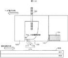
図1に本発明の磁気記録再生装置の構成例の一部である磁気記録再生ヘッドの概略図を示す。磁気記録再生ヘッドは、記録ヘッド部100と再生ヘッド部200から構成される、記録再生分離ヘッドである。記録ヘッド部100は高周波磁界を発生するための発振器110、記録ヘッド磁界を発生するための主磁極120、発振器110の磁化回転方向を制御するためのシールド130、発振器の媒体対向面方向の位置を調整するための第1の熱膨張素子150、発振器110と第1の熱膨張素子150の間の絶縁を取るための絶縁層140、主磁極に磁場を励磁するためのコイル160から構成される。本発明の特徴は発振器110の上部に第1の熱膨張素子150を設けていることであり、効率的に発振器110と主磁極120の媒体に対向する底面の媒体対向面方向の相対距離を変化させることが出来ることである。このための具体的な手段や効果について後述する。また、磁気記録再生ヘッド全体の磁気記録媒体に対する浮上量を制御するための第3の熱膨張素子を磁気記録再生装置の上部に置くことができる。第3の熱膨張素子は現行の磁気記録再生ヘッドにも用いられており、例えば特許文献3に構造が記載されている。第3の熱膨張素子は、例えば主磁極120や再生ヘッド部200上部に設置することができる。コイル160、発振器110、第1の熱膨張素子150への印加電流は図示はされていないが各々の構成要素ごとに設けられた電流供給端子により供給される。
FIG. 1 shows a schematic diagram of a magnetic recording / reproducing head which is a part of a configuration example of a magnetic recording / reproducing apparatus of the present invention. The magnetic recording / reproducing head is a recording / reproducing separation head composed of a
再生ヘッド部200は再生センサ210、下部磁気シールド220と上部磁気シールド230からなる構成である。再生センサ210は記録信号を再生する役割を担うことさえ出来れば特に特別な制限は必要がない。再生センサ210の構成としては、所謂GMR(Giant Magneto-Resistive)効果を有する再生センサであっても良いし、TMR(Tunneling Magneto-Resistive)効果を有する再生センサであっても良いし、EMR(Electro Mechanical Resonant)効果を有する再生センサであっても良い。また、外部磁界に対して逆極性の応答をする2つ以上の再生センサを有する所謂差動型再生センサであっても良い。また、下部磁気シールド220と上部磁気シールド230は再生信号品質の向上に重要な役割を担うため設けることが好ましい。さらに、図1には特に記載していないが、上部磁気シールド230は記録ヘッド部100の補助磁極としての役割を兼ね備えることができる。
The reproducing
図2は本発明が適用される磁気記録再生装置の構成例である。磁気記録媒体300をスピンドルモーター400にて回転させ、アクチュエーター500によってヘッドスライダー600を磁気記録媒体300のトラック上に誘導する。即ち磁気ディスク装置においてはヘッドスライダー600上に形成した再生ヘッド、及び記録ヘッドがこの機構に依って磁気記録媒体300上の所定の記録位置に近接して相対運動し、信号を順次書き込み、及び読み取るのである。アクチュエーター500はロータリーアクチュエーターであることが望ましい。記録信号は信号処理系700を通じて記録ヘッドにて媒体上に記録し、再生ヘッドの出力を、信号処理系700を経て信号として得る。さらに再生ヘッドを所望の記録トラック上へ移動せしめるに際して、本再生ヘッドからの高感度な出力を用いてトラック上の位置を検出し、アクチュエーターを制御して、ヘッドスライダーの位置決めを行うことができる。本図ではヘッドスライダー600、磁気記録媒体300を各1個示したが、これらは複数であっても構わない。また磁気記録媒体300は両面に記録情報を有して情報を記録してもよい。情報の記録がディスク両面の場合ヘッドスライダー600は磁気記録媒体300の両面に配置する。
FIG. 2 shows a configuration example of a magnetic recording / reproducing apparatus to which the present invention is applied. The
図3は本実施例における記録ヘッド部100および磁気記録媒体300の詳細な構成例である。本実施例では、磁気記録再生ヘッドは再生ヘッド部200が先頭で記録ヘッド部100が後方になる向きに、磁気記録媒体300の回転に対して相対的に進行する構成としているが、再生ヘッド部200が後方で記録ヘッド部100が前方になる向きに磁気記録媒体300の回転に対して相対的に進行する構成であったとしても本発明により得られる効果には何ら影響はない。
FIG. 3 is a detailed configuration example of the
図3に示す垂直記録媒体300の記録層は磁気的にABS面と垂直方向に磁化される。本実施例では、磁気記録媒体300は記録層301、軟磁性下地層302から構成される。記録層301の磁化の歳差運動周波数が発振器110の高周波磁界の発振周波数と概ね一致していることが好ましい。記録層301はCoCrPt系合金から構成され、膜厚が10 nm、飽和磁化(Ms)は300emu/cc であり、垂直異方性エネルギーは4.5x10⁶erg/cc であり、磁気記録媒体300の磁化の発振周波数は約45GHz程度になる。したがって、発振器110の発振周波数もこの45GHzに近づけることが高いSNR実現のため重要である。記録層301層の材料はCoCrPt系合金の以外の材料でも良く、垂直磁気異方性を持つ材料であることが好ましい。また、記録層301は異なる垂直異方性エネルギーを持つ複数の層から構成することが出来る。この場合は、何れかの層の磁化の共鳴周波数と発振器110の高周波磁界の発振周波数が概ね等しいことが好ましい。軟磁性下地層302は記録層301に印加する記録磁界を向上させる役割を担うが、必ずしも必要であるわけではない。さらに、磁気記録媒体300には記録層301や軟磁性下地層302以外の層を加えることが出来る。例えば、記録層301の上部に記録層301の腐食や、記録層301と磁気ヘッドスライダの直接接触による特性劣化抑制を目的とした保護膜を設けても良い。記録層301と軟磁性下地層302の間にこれらの層の磁気的な結合を抑制するための、中間層を設けてもよい。さらに、磁気記録媒体300は各ビットが連続して存在する所謂連続媒体でも良いし、複数のトッラク間に記録ヘッドにより書き込み不可能な非磁性である領域が設けられている所謂ディスクリートトラックメディアでも良い。また、基板上に、凸状の磁性パターンと磁性パターン間の凹部を充填する非磁性体とを含む所謂パターンド媒体でもよい。
The recording layer of the
磁気ヘッド部100の発振器110は、高周波磁界を発生するFGL111、スピン透過性の高い材料からなる中間層112、FGL111にスピントルクを与えるためのスピン注入固定層113、FGLの磁化回転を安定化させるための回転ガイド層114から構成される。発振器110の総膜厚の下限は特にないが、上限は200 nm程度である。これは発振器110の総膜厚が厚すぎると主磁極120とシールド130間の距離が広がりすぎるため、発振器110に印加される主磁極120からの磁界の減衰が激しくなり、FGL111の高周波発振が持続できなくなるためである。本構成例のFGL111の材料はFe70Co30であり、膜厚は20 nmである。Fe70Co30の飽和磁化は2.4 Tであり、高い高周波磁界を発生することが出来る。FGL111の材料としてはFeCo合金の他に、NiFe合金やCoFeGe、CoMnGe、CoFeAl、CoFeSi、CoMnSiなどのホイスラー合金、TbFeCoなどのRe-TM系アルモファス系合金、CoCr系合金などでもよい。また、CoIrなど負の垂直異方性エネルギーを持つ材料でも良い。FGL111の膜厚は5 nm以上30 nm以下が好ましい。5 nm以上に設定するのは、膜厚が薄すぎると高周波磁界強度が低下しすぎるためであり、30 nm以下に設定するのは膜厚が厚すぎるとFGL111が多磁区化し磁界強度の低下を招くためである。本実施例の中間層112はCuであり、膜厚は2 nmである。中間層112の材料としては非磁性体の伝導材料であることが好ましく、例えばAu、Ag、Pt、Ta、Ir、Al、Si、Ge、Tiなどを用いることが出来る。本実施例のスピン注入層113はCo/Ptであり膜厚は10 nmである。また、本実施例に用いたCo/PtのHkは8 kOeである。スピン注入層113には垂直異方性を持った材料を用いることによりFGL111の発振を安定させることが出来、例えばCo/Ptの他にCo/Ni、Co/Pd、CoCrTa/Pd などの人工磁性材料を用いることが好ましい。また、発振の安定性は若干失われるがFGL111と同様の材料を用いることも出来る。本実施例の回転ガイド層114は垂直異方性エネルギーを持ったCo/Niであり、膜厚は10 nmである。また、本構成例におけるCo/NiのHkは5 kOeである。回転ガイド層114の構成もスピン注入固定層113と同様の材料を用いることが好ましい。以上のような発振器110の構成とすることにより、40 GHz以上の高周波で、磁気記録媒体300の記録層に1.5 kOe以上の高い高周波磁界を印加することができる。
The
本実施例の主磁極120とシールド130の構成としては、飽和磁化が大きく、結晶磁気異方性がほとんどないCoFe合金とした。図4にヘッド進行方向に対向する面から見たときの主磁極120と発振器110の模式図を示す。発振器110は主磁極120の中央付近に配置されることが好ましい。発振器110のトラック幅方向の幅(Two)の狙い値は40 nmであり、理想的にはこの幅が磁気的に記録される幅(MWW)となる。トラック幅方向の主磁極の幅(PW)の狙い値は100 nmとした。発振器の素子高さ方向の幅(SHo)の狙い値は40 nmである。TwoとSHoはその比が0.5以上2以下になるように設計することが、FGL内の磁区の単磁区化の観点から好ましい。TwoとSHoの比がこの範囲外になると、形状異方性磁界が増大し面内等方向の発振が阻害されるためである。本実施例における主磁極のトラック幅方向の幅(PW)は100 nmであり、高さ方向に底面に対して略垂直な主磁極のネック高さ(TH)の狙い値を60 nmとした。発振器110および主磁極120のこれらの幾何幅の設計値(狙い値)は発振器110、主磁極120やシールド130の構造により高い記録密度が得られるように自在に設計することが出来る。
The configuration of the main
図5は第1の熱膨張素子150の詳細な構成例である。第1の熱膨張素子150は薄膜抵抗体151、熱膨張素子電極152とその間隙のアルミナ153から構成される。薄膜抵抗体151として本実施例では、材質がNiFe合金の細線を蛇行させ、間隙はアルミナで埋めて発熱体を形成した。抵抗値は約50オームである。薄膜抵抗体151の材料にはパーマロイの他にCuなど熱膨張係数の大きい材料を用いることが好ましい。
FIG. 5 is a detailed configuration example of the first
図6に、主磁極120の底面と磁気記録媒体300の最表面の媒体対向面方向の距離に対する、発振器110の底面と磁気記録媒体300の最表面の媒体対向面方向の距離(発振器の浮上量)の変化量と、第1の熱膨張素子150に印加する電力との関係を示す。以後、発振器110の底面と磁気記録媒体300の最表面の媒体対向面方向の距離を「発振器の浮上量」、主磁極120の底面と磁気記録媒体300の最表面の媒体対向面方向の距離を「主磁極の浮上量」と記載する。図6から、発振器の浮上調整の効率はヒーター電力が100 mWで5 nm程度であり、現実的に印加可能な電力範囲で10 nm程度の発振器110単体の浮上量調整が可能である。
FIG. 6 shows the distance of the bottom surface of the
「最適化方法及び効果」
以下に、実施例1を基に、本発明の特徴である磁気記録ヘッドおよび発振器110の製造のばらつきに起因する記録磁界強度および高周波磁界強度のばらつきを補償する発振器110の浮上量補正の方法とその効果について説明する。以後説明する条件は、高周波磁界強度及び記録磁界強度が設計値通りである場合(理想条件)、高周波磁界強度が狙いよりも低下した場合(条件1)、記録磁界強度が狙いよりも増加した場合(条件2)、および高周波磁界強度が狙いよりも低下し、かつ、記録磁界強度が狙いよりも増加した場合(条件3)である。本実施例では高周波磁界強度が狙いより増加した場合、記録磁界強度が狙いより低下した場合、とそれらが同時に起こった場合には、特性改善の効果を有さない。この場合は、特に実施例2の構成が有効である。
"Optimization methods and effects"
The method for correcting the flying height of the
図7に高記録密度を実現するために必要な高周波磁界強度と記録磁界強度の一例を示す。ここで、発振器110の高周波磁界の発振周波数は、発振器に通電する電流値の最適化により、45 GHzに設定されている。図7に示す条件では発振器の浮上量及び主磁極の浮上量は共に3 nmとなるように、第3の熱膨張素子に電力を印加した。狙い通りの高周波磁界強度と記録磁界強度が得られた条件(理想条件)においては、2 Tb/in2もの高い記録密度が得られる。しかし、条件1、条件2や条件3の様に理想条件から高周波磁界強度や記録磁界強度、もしくはその両方が乖離した場合には、記録密度は1.2 Tb/in2から1.6 Tb/in2 の範囲で大きく低下する。
FIG. 7 shows an example of the high-frequency magnetic field strength and the recording magnetic field strength necessary for realizing a high recording density. Here, the oscillation frequency of the high-frequency magnetic field of the
条件1、2、3において、理想条件から高周波磁界強度及び記録磁界強度が乖離してしまう代表的な要因を表1を用いて説明する。表1には、理想条件と条件1、2、3における記録磁界強度Hrec、高周波磁界強度HAC、主磁極の浮上量、発振器の浮上量、主磁極のネック高さTH、および発振器の素子高さSHo、1500 kfci(flux-change-per-inch) におけるSNR、MWW、および記録密度 A.D(Areal Density)の具体的な数値を示す。高周波磁界強度の理想条件からの低下若しくは増加は、発振器110の素子高さ方向形成プロセスの製造誤差に起因するSHoのばらつきが最も起こりうる要因である。例えば、条件1ではSHoが理想条件である40 nmから30 nmに減少しているために、高周波磁界強度が理想条件の1.6 kOeから1.5 kOeに減少している。SHoが高いほど高周波磁界強度が大きい理由は、SHoが高いほどFGLの側面からの磁界強度が増加するためである。一方、記録磁界強度の理想条件からの乖離は、主磁極120の素子高さ方向形成プロセスの製造誤差に起因するTHのばらつきが最も起こりうる要因である。例えば、条件2ではTHが理想条件である60 nmから50 nmに減少しているために、記録磁界強度が理想条件の10 kOeから11 kOeまで増加している。THが小さいほど記録磁界強度が増加する理由は、THが小さいほど主磁極の媒体対向面方向上部の主磁極幅が広がった領域が磁気記録媒体に近づくためである。条件3はSHoが理想条件の40 nmから30 nmに減少し、THが理想条件の60 nmから50 nmに減少している場合を想定している。現実的にはSHoやTHの素子高さ形成は製造プロセスにおいて同時に行われるので、SHoとTHの両方ともが理想条件より減少してしまう、もしくは増加してしまうのが最も起こりえる状況である。なお、特に上述の要因の以外の理由によって高周波磁界強度および記録磁界強度の理想条件からの乖離が引き起こされたのもであっても、本発明の効果が特に制限されるものではない。
Under

次に、高周波磁界強度および記録磁界強度が理想条件から乖離すると記録密度が大きく低下する理由を図7と表1を用いて以下に説明する。まず、記録密度は線記録密度を決定する信号の品質(SNR)とトラック密度を決定する磁気トラック幅(MWW)からほぼ決定され、高いSNRと狭MWWの両方を満足できなければ高記録密度は得られない。表1から2.0 Tb/in2の記録密度を実現できる条件は、SNRが約15 dBでMWWが40 nmのときである。15 dB程度のSNRを得るためには、1.6 kOe以上の高周波磁界強度と9.5 kOe以上の記録磁界強度の両方を満足する必要がある。どちらかがこの条件を下回るとSNRは急激に劣化するため、記録密度の低下を招く。例えば、条件1では高周波磁界強度が1.5 kOeまで低下しているために、SNRが12 dBと大きく低下している。一方、40 nmの狭MWWを実現するためには1.7 kOe以下の高周波磁界強度と10.3 kOe以下の記録磁界強度の両方を満足する必要がある。しかし、高周波磁界強度と記録磁界強度のどちらかが高すぎるとMWWの急激な増大を招いてしまう。例えば、条件2または3では記録磁界強度が11 kOeにまで増加しているため、MWWが60 nm程度にまで増加してしまう。したがって、高周波磁界強度と記録磁界強度の両方の最適化が高記録密度実現には必要なのである。
Next, the reason why the recording density is greatly reduced when the high-frequency magnetic field strength and the recording magnetic field strength deviate from the ideal conditions will be described below with reference to FIG. First, the recording density is almost determined from the signal quality (SNR) that determines the linear recording density and the magnetic track width (MWW) that determines the track density. If both the high SNR and narrow MWW cannot be satisfied, the high recording density I can't get it. From Table 1, the condition that can achieve a recording density of 2.0 Tb / in 2 is when the SNR is about 15 dB and the MWW is 40 nm. In order to obtain an SNR of about 15 dB, it is necessary to satisfy both a high-frequency magnetic field strength of 1.6 kOe or more and a recording magnetic field strength of 9.5 kOe or more. If either of these conditions falls below this condition, the SNR deteriorates rapidly, leading to a decrease in recording density. For example, in
しかしながら、条件1、2、3において、本実施例の特色である発振器110と主磁極120の相対距離調整を行わない場合は、磁気記録ヘッドの製造後の記録電流や第3の熱膨張素子印加電力などの最適により、記録密度を理想条件にて達成できる2.0 Tb/in2 まで向上させることは不可能である。例えば、条件2の場合は記録電流を変化させることにより記録磁界強度は最適化できたとしても、発振周波数が変化するため返って記録密度の低下を招きかねない。また、第3の熱膨張素子に印加す電力を制御すると、発振器の浮上量と主磁極の浮上量を制御できるので高周波磁界強度と記録磁界強度を同時に変化させられるが、両者は連動して変化するため高周波磁界強度と記録磁界強度の両方の理想条件を同時に満たすことは出来ない。図7に示した3本の実線は理想条件及び条件1、2、3において第3の熱膨張素子に電力を印加した時の高周波磁界強度と記録磁界強度の変化を示しており、第3の熱膨張素子の制御だけでは高い記録密度が得られないことが確認できる。図8、9にそれぞれ高周波磁界強度の発振器の浮上量依存性と記録磁界強度の主磁極の浮上量依存性を示す。図8と図9に示すように高周波磁界強度と記録磁界強度は浮上量が10 nm程度までは概ね浮上量に対して線形に変化するので、図7中の3本の実線のように、記録磁界強度と高周波磁界強度の比は常に一定になるのである。
However, if the relative distance between the
具体的な条件1、2、3における本発明構造の特色を活かした発振器110と主磁極120の浮上量調整方法の一例を示す。
An example of a method for adjusting the flying height of the
条件1における高周波磁界強度の最適化方法およびのその効果を表2を用いて説明する。条件1においては高周波磁界強度のみが理想条件から減少しているので、高周波磁界強度のみを増加させるために、発振器110のみの浮上量を低下させれば良い。図8より、理想条件の高周波磁界強度である1.7 kOeを得るためには発振器の浮上量を3 nmから2 nm低減し、1 nmにすれば良いことが分かる。このためには、図6より第1の熱膨張素子150へ印加するヒーター電力を40 mWとすれば良い。このときの高周波磁界強度、記録磁界強度と面記録密度を表2の条件1’として示した。以上の方法により、条件1における高周波磁界強度の減少を回復することが可能となり、記録密度も理想条件と同じ値まで回復することが出来た。
A method for optimizing the high-frequency magnetic field intensity under
条件2における記録磁界強度の最適化方法およびのその効果を表3を用いて説明する。条件2においては記録磁界強度のみが理想条件から増加しているので、記録磁界強度のみを減少させるために、主磁極120のみの浮上量を増加させれば良い。図9より、理想条件の記録磁界強度である10 kOeを得るためには主磁極の浮上量を3 nmから5 nmに第3の熱膨張素子を用いて増加させれば良いことが分かる。しかし、このときは発振器の浮上量も5 nmに増加してしまい、記録密度としては返って低下してしまう。この状態が条件2’である。そこで、発振器の浮上量を5 nmから理想条件である3 nmに戻すために、第1の熱膨張素子150へヒーター電力を40 mWを加える。このときの状態が条件2’’であり、理想条件と同等の高周波磁界強度と記録磁界強度が実現できる。以上の方法により、条件2における記録磁界強度の増加を回復することが可能となり、記録密度も理想条件と同じ値まで回復することが出来た。
The method for optimizing the recording magnetic field intensity under
条件3における記録磁界強度の最適化方法およびのその効果を表4を用いて説明する。条件3においても浮上量の最適化の手順は条件2と同じであり、まず理想条件の記録磁界強度である10 kOeを得るためには主磁極の浮上量を3 nmから5 nmに第3の熱膨張素子を用いて増加させれば良い。しかし、このときは発振器の浮上量も5 nmに増加してしまい、高周波磁界強度は元の1.5 kOeから1.3 kOeへ減少し、記録密度としては返って低下してしまう。このときの状態が条件3’である。そこで、高周波磁界強度を1.3 kOeから理想条件の1.7 kOeまで増加させるために、図8に示す高周波磁界強度と発振器の浮上量の関係から、発振器の浮上量を5 nmから1 nmにまで低下させる必要がある。このとき発振器の浮上量は4 nm下げれば良いので、図6より第1の熱膨張素子150へ印加するヒーター電力を100 mWとすれば良い。このときの状態が条件3’’であり、理想条件と同等の高周波磁界強度と記録磁界強度が実現できる。以上の方法により、条件3における記録磁界強度と高周波磁界強度の両方を理想条件に最適化することが可能となり、記録密度も理想条件と同じ値まで回復することが出来た。
The method for optimizing the recording magnetic field strength under
以上のように、本実施例において、発振器110と主磁極120の製造誤差に起因する発振器110からの高周波磁界強度の狙い値からの低下、主磁極120からの記録磁界強度の狙い値からの増加、およびこれらが同時に生じる場合に起こる記録密度の低下を発振器110と主磁極120の浮上量を独立に調整することによって、記録磁界強度と高周波磁界強度を独立に調整することが可能となり、記録密度の低下を抑制することが出来る。
As described above, in this embodiment, the high-frequency magnetic field intensity from the
本発明の第2の実施例を以下に示す。本実施例は記録ヘッド部100の構成のみが実施例1に記載の構成とは異なる。従って、実施例1と重複する記録ヘッド部100以外の磁気記録再生装置の説明については省略する。本実施例における記録ヘッド部100の拡大図を図10に示す。なお、図10では第1の熱膨張素子150や第3の熱膨張素子には電力を印加していない状態を示している。本実施例は発振器110の底面が主磁極120の底面よりも素子高さ方向に高い位置にあることが特徴である。本実施例では第1の熱膨張素子150に電力を印加しないときの発振器110と主磁極120の素子高さ方向の相対距離を4 nmであるとした。なお、図10ではシールド130は発振器110と同じ高さ位置にあるが、主磁極120と同じ素子高さ位置にあっても良い。本実施例も実施例1の構成と同様に、主磁極120および発振器110からの記録磁界強度および高周波磁界強度を独立に調整できることが特徴であり、これにより製造誤差による磁界強度の狙い値からの乖離を補償し、記録密度を向上することが出来る。ただし、実施例1では記録磁界強度が狙い値より増加した場合、高周波磁界強度が狙い値より低減した場合、およびこれらが同時に起こった場合に有効であったが、実施例2ではこれらの場合に加えて記録磁界強度が狙い値より低下した場合、高周波磁界強度が狙い値より増加した場合、およびこれらが同時に起こった場合についても有効である。
A second embodiment of the present invention is shown below. In the present embodiment, only the configuration of the
以下に、記録磁界強度や高周波磁界強度が狙い値から乖離した場合の具体的な発振器および主磁極の浮上量調整方法について説明する。図11および表5に記録磁界強度や高周波磁界強度が狙い通りである理想条件、記録磁界強度が理想条件より増加し高周波磁界強度が狙いより低下した条件3、記録磁界強度が理想条件より低下し高周波磁界強度が狙いより増加した条件4におけるこれらの具体的な数値とこのとき得られる記録密度を示す。理想条件と条件3は実施例1で用いた設定と基本的に同一である。唯一異なる点は、発振器の浮上量を主磁極の浮上と同じにするために、第1の熱膨張素子150には既に70 mWの電力が加えられている点である。
A specific oscillator and main pole flying height adjustment method when the recording magnetic field strength and the high-frequency magnetic field strength deviate from the target values will be described below. 11 and Table 5 show the ideal condition where the recording magnetic field strength and the high-frequency magnetic field strength are as intended, the
条件3および4において、発振器および主磁極の浮上量を最適化する具体的な手順を説明する。条件3においては基本的に実施例1の手順と同じであり、表4の条件3’’に記載の発振器の浮上量および主磁極の浮上量となるように第1の熱膨張素子150、および第3の熱膨張素子を調整すればよい。ただし、実施例1の構成において条件3’’とするには第1の熱膨張素子150に100 mWの電力を加えれば良かったが、本構成例においては条件3の時点で既に70 mWの電力が加えられているので、最終的に170mWの電力を加える必要がある。また、本実施例を用いて実施例1に記載の条件1、2、3の最適化を行うためには、熱膨張素子に印加する電力を実施例1の時よりも70 mWだけ大きく印加することで対応できる。
A specific procedure for optimizing the flying height of the oscillator and the main magnetic pole under
条件4における最適化の手順も基本的に条件3と同一である。最適化の例を図8と図9と表6を用いて説明する。初めに記録磁界強度の理想条件からの減少を回復するために、第3の熱膨張素子を用いて主磁極の浮上量を低減させる。主磁極の浮上量は図9の記録磁界強度と浮上量の関係から1 nmに設定すれば良い。このとき、同時に発振器の浮上量も1 nmに低下しているので、高周波磁界強度は図8から約2.0 kOeになっていることがわかる。そこで、高周波磁界強度を理想条件の1.7 kOにまで低減させる。このためには、図8の高周波磁界強度と発振器の浮上量の関係から、発振器の浮上量は4.5 nmにすれば良い。現在の発振器の浮上量は1 nmとなっているので、3.5 nmだけ発振器の浮上量を増加させれば良い。現在は70 mWの電力を印加し浮上量を4 nm下げているので、浮上量を3.5 nm上げるには図6から、ヒーター電力を20 mWとすれば良いことが分かる。
The optimization procedure in
以上のような構成と最適化により、実施例2に記載の構成例において実施例1の構成よりも広い範囲の記録磁界強度および高周波磁界強度のばらつきを保障し、高い記録密度を実現できる。 With the configuration and optimization as described above, in the configuration example described in the second embodiment, variations in the recording magnetic field strength and the high-frequency magnetic field strength in a wider range than the configuration of the first embodiment can be ensured, and a high recording density can be realized.
本発明の第3の実施例を以下に示す。本実施例の構成は、記録部100の構成のみが実施例1に記載の構成とは異なる。よって、実施例1と重複する記録部100以外の磁気記録再生装置の説明については省略する。本実施例における記録部100の拡大図を図12に示す。実施例1の構成において第1の熱膨張素子150が発振器の上部に位置していたのに対し、本構成例では発振器110から見てシールド130の後方に第2の熱膨張素子154を設置する。また、第2の熱膨張素子154とシールド130の間に絶縁層141を設ける。なお、図12では第2の熱膨張素子154には電力を印加していない状態を示している。実施例1や2の構成では発振器110のFGL111と主磁極120の間に回転ガイド層114を設けていたが、本構成例では発振器110のFGL111と主磁極120の間は空隙となっている。このような構成とすることで、第2の熱膨張素子154への電力印加によるFGL-主磁極間距離を大きく変化させることが可能になる。別の構成として、FGL111と主磁極120の間に回転ガイド層114を設け、回転ガイド層と主磁極120の間に空隙を設けた構成であっても良い。また、空隙の代わりにヤング率の小さい導電性有機物材料などの材料を用いても良い。以上の構成以外は実施例1や実施例2の構成例と全く同一である。本実施例はFGL111と主磁極120間のヘッド進行方向の距離を調整できることが最大の特徴であり、これにより高周波磁界強度の調整が可能となり、結果的に発振器110や主磁極120の製造誤差に起因する高周波磁界強度や記録磁界強度のばらつきを補償できる。
A third embodiment of the present invention will be described below. The configuration of the present embodiment is different from the configuration described in the first embodiment only in the configuration of the
本実施例における、第2の熱膨張素子154への電力印加によるFGL-主磁極間距離の最適化の具体的な方法と効果を図13、図14と表7を用いて説明する。図13にFGL-主磁極間距離と第2の熱膨張素子154に印加するヒーターパワーの関係を示す。本実施例においては、第2の熱膨張素子154に電力を印加しない状態のFGLと主磁極間の空隙を14 nmに設定している。ヒータパワーを増加すると第2の熱膨張素子154の膨張に伴いFGL-主磁極間距離は14 nmより小さくなる。
A specific method and effect of optimizing the FGL-main magnetic pole distance by applying power to the second
図14に高周波磁界強度とFGL-主磁極間距離の関係を示す。FGL-主磁極間距離が低下するほど高周波磁界強度は増加するので、高周波磁界強度は第2の熱膨張素子154への電力の制御により制御が可能である。
FIG. 14 shows the relationship between the high-frequency magnetic field strength and the FGL-main magnetic pole distance. Since the high-frequency magnetic field strength increases as the FGL-main magnetic pole distance decreases, the high-frequency magnetic field strength can be controlled by controlling the power to the second
表7に発振器110が設計狙い通りに製造できた時の各部の幾何寸法や高周波磁界強度と記録磁界強度を示した理想条件と、発振器110からの高周波磁界強度が狙い値から増加した条件5を示す。本実施例における理想条件はFGL-主磁極間距離が10 nmなので、図13に記載のFGL-主磁極間距離と第2の熱膨張素子154へ印加するヒータ電力の関係を用いて、FGL-主磁極間距離が14 nmから10 nmになるように140 mWの電力を印加している。一方、条件5は理想条件の発振器110のSHoの狙い値である40 nmよりも増加し60 nmとなっている。このため、高周波磁界強度が理想条件の1.7 kOeよりも増加し1.9 kOeとなっていることが表7から分かる。高周波磁界強度を1.9 kOeから1.7 kOeにまで低減する必要があり、このためには図14からFGL-主磁極間距離を10 nmから12 nmに増加させればよいことが分かる。図13からFGL-主磁極間距離を12 nmにするためには、第2の熱膨張素子154に印加する電力を60 mWにすればよいことが分かる。以上のような手順により、発振器110の製造誤差に起因する高周波磁界強度のばらつきを補償することが可能であり、それに伴う記録密度の低下を抑制することが出来る。
Table 7 shows ideal conditions indicating the geometric dimensions of each part, the high-frequency magnetic field strength and the recording magnetic field strength when the
本実施例では高周波磁界強度が理想条件から乖離した場合のみを例に説明したが、記録磁界強度、もしくは高周波磁界強度と記録磁界強度の両方が理想条件から乖離した場合であっても、実施例1や2と同様に第3の熱膨張素子の制御と第2の熱膨張素子154の調整を組み合わせることにより、高周波磁界強度と記録磁界強度の最適化が可能である。
In the present embodiment, only the case where the high frequency magnetic field strength deviates from the ideal condition has been described as an example. However, even if the recording magnetic field strength or both the high frequency magnetic field strength and the recording magnetic field strength deviate from the ideal condition, the embodiment Similarly to 1 and 2, by combining the control of the third thermal expansion element and the adjustment of the second
本発明の第4の実施例を以下に示す。本実施例の構成は、記録ヘッド部100の構成のみが実施例1に記載の構成とは異なる。よって、実施例1と重複する記録ヘッド部100以外の磁気記録再生装置の説明については省略する。本実施例における記録ヘッド部100の拡大図を図15に示す。本実施例の特徴は、第1の熱膨張素子150と第2の熱膨張素子154をそれぞれ発振器110の上部と主磁極120から見てシールド130の後方に備えることである。本実施例においても、基本的な高周波磁界強度や記録磁界強度を調整するという概念は実施例1、2、3と同じであるが、より広い範囲にわたり高周波磁界強度と記録磁界強度の調整が可能であり、実施例1、2、3よりも製造誤差の許容範囲が広いことが特徴である。
A fourth embodiment of the present invention will be described below. The configuration of the present embodiment is different from the configuration described in the first embodiment only in the configuration of the
100:記録ヘッド部
110:発振器
111:高周波磁界発生層(FGL)
112:中間層
113:スピン注入固定層
114:回転ガイド層
120:主磁極
130:シールド
140:絶縁層
141:絶縁層
150:第1の熱膨張素子
151:薄膜抵抗体
152:熱膨張素子電極
153:アルミナ
154:第2の熱膨張素子
160:コイル
200:再生ヘッド部
210:再生センサ
220:下部磁気シールド
230:上部磁気シールド
300:磁気記録媒体
301:記録層
302:軟磁性下地層
400:スピンドルモーター
500:アクチュエーター
600:ヘッドスライダー
700:信号処理系。
100: Recording head part 110: Oscillator 111: High frequency magnetic field generation layer (FGL)
112: Intermediate layer 113: Spin injection pinned layer 114: Rotating guide layer 120: Main magnetic pole 130: Shield 140: Insulating layer 141: Insulating layer 150: First thermal expansion element 151: Thin film resistor 152: Thermal expansion element electrode 153 : Alumina 154: Second thermal expansion element 160: Coil 200: Playback head unit 210: Playback sensor 220: Lower magnetic shield 230: Upper magnetic shield 300: Magnetic recording medium 301: Recording layer 302: Soft magnetic underlayer 400: Spindle Motor 500: Actuator 600: Head slider 700: Signal processing system.
Claims (9)
前記発振器の媒体対向面とは反対側に、絶縁層を介して、隣接して設けた第1の熱膨張素子と、前記第1の熱膨張素子に電流を通電するための電極を含む、前記発振器の底面と前記主磁極の底面の媒体対向面における高さ方向の相対距離を調整する機構を備え、
前記主磁極からの磁界強度と前記発振器からの高周波磁界強度を独立に調整するものであることを特徴とする高周波アシスト磁気記録ヘッド。 In a high-frequency assisted magnetic recording head comprising a main magnetic pole that generates a recording magnetic field for recording on a magnetic recording medium, a shield, and an oscillator that generates a high-frequency magnetic field disposed between the main magnetic pole and the shield ,
A first thermal expansion element provided adjacent to the oscillator on the side opposite to the medium facing surface via an insulating layer; and an electrode for passing an electric current to the first thermal expansion element, A mechanism for adjusting the relative distance in the height direction of the medium facing surface between the bottom surface of the oscillator and the bottom surface of the main magnetic pole,
A high-frequency assisted magnetic recording head characterized by independently adjusting the magnetic field intensity from the main magnetic pole and the high-frequency magnetic field intensity from the oscillator.
前記第1の熱膨張素子に電流を通電しない状態で、前記発振器の底面が前記主磁極の底面よりも媒体対向面における高さ方向に記録媒体から離れる高い位置にあることを特徴とする高周波アシスト磁気記録ヘッド。 The high frequency assisted magnetic recording head according to claim 1 ,
The high-frequency assist is characterized in that the bottom surface of the oscillator is at a higher position away from the recording medium in the height direction on the medium facing surface than the bottom surface of the main magnetic pole in a state where no current is supplied to the first thermal expansion element. Magnetic recording head.
前記第1の熱膨張素子に電流を通電しない状態で、前記発振器の底面が前記主磁極の底面と同一面に位置していることを特徴とする高周波アシスト磁気記録ヘッド。 The high frequency assisted magnetic recording head according to claim 1 ,
A high-frequency assisted magnetic recording head, wherein a bottom surface of the oscillator is located flush with a bottom surface of the main magnetic pole in a state where no current is supplied to the first thermal expansion element.
前記シールドに対して前記発振器とは反対側に、絶縁層を介して、設けた第2の熱膨張素子と、前記第2の熱膨張素子に電流を通電するための電極と、前記主磁極と前記発振器との間に設けた空隙とを含む、前記発振器と前記主磁極のヘッド進行方向の相対距離を調整する機構を備えることを特徴とする高周波アシスト磁気記録ヘッド。 In a high-frequency assisted magnetic recording head comprising a main magnetic pole that generates a recording magnetic field for recording on a magnetic recording medium, a shield, and an oscillator that generates a high-frequency magnetic field disposed between the main magnetic pole and the shield ,
A second thermal expansion element provided on the opposite side of the shield from the oscillator via an insulating layer; an electrode for energizing the second thermal expansion element; and the main pole; A high-frequency assisted magnetic recording head comprising a mechanism for adjusting a relative distance between the oscillator and the main pole in the head traveling direction, including a gap provided between the oscillator and the oscillator .
前記シールドに対して前記発振器とは反対側に、絶縁層を介して、設けた第2の熱膨張素子と、前記第2の熱膨張素子に電流を通電するための電極と、前記主磁極と前記発振器との間に設けた空隙とを含む、前記発振器と前記主磁極のヘッド進行方向の相対距離を調整する機構を有することを特徴とする高周波アシスト磁気記録ヘッド。 The high frequency assisted magnetic recording head according to claim 1, further comprising:
A second thermal expansion element provided on the opposite side of the shield from the oscillator via an insulating layer; an electrode for energizing the second thermal expansion element; and the main pole; A high-frequency assisted magnetic recording head comprising a mechanism for adjusting a relative distance between the oscillator and the main pole in the head traveling direction, including a gap provided between the oscillator and the oscillator .
前記主磁極の媒体対向面とは反対側に設けた第3の熱膨張素子を含む、前記主磁極と前記発振器の媒体対向面における高さ方向の位置を同時に調整する機構を有することを特徴とする高周波アシスト磁気記録ヘッド。 The high frequency assisted magnetic recording head according to any one of claims 1 to 5 ,
And a third thermal expansion element provided on a side opposite to the medium facing surface of the main magnetic pole, and a mechanism for simultaneously adjusting the height direction positions of the main magnetic pole and the medium facing surface of the oscillator. High frequency assisted magnetic recording head.
前記発振器が、高周波磁界発生層を含むことを特徴とする高周波アシスト磁気記録ヘッド。 The high frequency assisted magnetic recording head according to any one of claims 1 to 6 ,
The high-frequency assisted magnetic recording head, wherein the oscillator includes a high-frequency magnetic field generation layer.
前記発振器が、スピン注入固定層と、中間層と、高周波磁界発生層と、回転ガイド層とを備えることを特徴とする高周波アシスト磁気記録ヘッド。 The high frequency assisted magnetic recording head according to claim 7 ,
The high-frequency assisted magnetic recording head, wherein the oscillator includes a spin injection fixed layer, an intermediate layer, a high-frequency magnetic field generation layer, and a rotation guide layer.
Priority Applications (2)
| Application Number | Priority Date | Filing Date | Title |
|---|---|---|---|
| JP2010048120A JP5658470B2 (en) | 2010-03-04 | 2010-03-04 | High frequency assisted magnetic recording head and magnetic recording / reproducing apparatus using the same |
| US13/019,002 US8582225B2 (en) | 2010-03-04 | 2011-02-01 | Microwave-assisted magnetic recording head and magnetic read/write apparatus using the same |
Applications Claiming Priority (1)
| Application Number | Priority Date | Filing Date | Title |
|---|---|---|---|
| JP2010048120A JP5658470B2 (en) | 2010-03-04 | 2010-03-04 | High frequency assisted magnetic recording head and magnetic recording / reproducing apparatus using the same |
Publications (2)
| Publication Number | Publication Date |
|---|---|
| JP2011187092A JP2011187092A (en) | 2011-09-22 |
| JP5658470B2 true JP5658470B2 (en) | 2015-01-28 |
Family
ID=44531143
Family Applications (1)
| Application Number | Title | Priority Date | Filing Date |
|---|---|---|---|
| JP2010048120A Expired - Fee Related JP5658470B2 (en) | 2010-03-04 | 2010-03-04 | High frequency assisted magnetic recording head and magnetic recording / reproducing apparatus using the same |
Country Status (2)
| Country | Link |
|---|---|
| US (1) | US8582225B2 (en) |
| JP (1) | JP5658470B2 (en) |
Families Citing this family (37)
| Publication number | Priority date | Publication date | Assignee | Title |
|---|---|---|---|---|
| US9305586B2 (en) * | 2009-02-04 | 2016-04-05 | HGST Netherlands B.V. | Microwave-assisted magnetic recording device and method of formation thereof |
| JP5451096B2 (en) * | 2009-02-04 | 2014-03-26 | エイチジーエスティーネザーランドビーブイ | Magnetic head |
| US8374060B2 (en) * | 2011-03-11 | 2013-02-12 | Tdk Corporation | Thermally-assisted magnetic recording method for writing data on a hard disk medium |
| JP5117606B1 (en) * | 2011-09-13 | 2013-01-16 | 株式会社日立製作所 | Magnetic recording head, manufacturing method thereof, and magnetic disk apparatus |
| JP5416746B2 (en) | 2011-09-29 | 2014-02-12 | 株式会社日立製作所 | Magnetic storage device, head drive control device, and head drive control method |
| US8760779B2 (en) | 2011-12-30 | 2014-06-24 | HGST Netherlands B.V. | Energy-assisted magnetic recording head and systems thereof with environmental conditions control |
| JP5808273B2 (en) | 2012-03-01 | 2015-11-10 | 株式会社日立製作所 | Magnetic head, head drive control device, magnetic storage device, and control method thereof |
| JP5902025B2 (en) * | 2012-04-23 | 2016-04-13 | 株式会社日立製作所 | SERVO PATTERN BY MICROWAVE-ASSISTED MAGNETIC RECORDING, VERTICAL MAGNETIC RECORDING MEDIUM, MAGNETIC STORAGE DEVICE, AND METHOD FOR MANUFACTURING THE SAME |
| JP5894868B2 (en) * | 2012-06-18 | 2016-03-30 | 株式会社日立製作所 | Microwave assisted magnetic recording system and magnetic storage device |
| US9047888B2 (en) * | 2012-12-20 | 2015-06-02 | HGST Netherlands B.V. | MAMR head adapted for high speed switching |
| JP2013149340A (en) * | 2013-03-01 | 2013-08-01 | Hitachi Ltd | Magnetic memory device, head drive control device, and head drive control method |
| US8842387B1 (en) | 2013-03-14 | 2014-09-23 | HGST Netherlands B.V. | Microwave-assisted magnetic recording (MAMR) head with highly resistive magnetic material |
| JP5848729B2 (en) * | 2013-07-26 | 2016-01-27 | 株式会社日立製作所 | Magnetic storage device, head drive control device, and head drive control method |
| US9202528B2 (en) * | 2013-09-27 | 2015-12-01 | HGST Netherlands B.V. | MAMR head with recessed STO |
| US8995088B1 (en) | 2013-10-22 | 2015-03-31 | HGST Netherlands B.V. | Heat sink for a spin torque oscillator (STO) in microwave assisted magnetic recording (MAMR) |
| US9230597B2 (en) * | 2013-11-01 | 2016-01-05 | HGST Netherlands B.V. | Magnetic head having a spin torque oscillator (STO) with a hybrid heusler field generation layer (FGL) |
| US9007723B1 (en) | 2013-12-13 | 2015-04-14 | HGST Netherlands B.V. | Microwave-assisted magnetic recording (MAMR) head employing advanced current control to establish a magnetic resonance state |
| JP2015149112A (en) | 2014-02-07 | 2015-08-20 | 株式会社東芝 | Magnetic recording head and disk unit including the same |
| US9406315B2 (en) * | 2014-02-12 | 2016-08-02 | HGST Netherlands B.V. | AF-mode STO with negative Hk spin polarization layer |
| US9142227B1 (en) | 2014-09-08 | 2015-09-22 | HGST Netherlands B.V. | Microwave assisted magnetic recording (MAMR) write head and system |
| JP2017068883A (en) * | 2015-09-30 | 2017-04-06 | 株式会社東芝 | Magnetic head, disk device including the same, and manufacturing method of magnetic head |
| US9640203B1 (en) | 2016-02-23 | 2017-05-02 | Seagate Technology Llc | Multi-frequency microwave assisted magnetic recording apparatus and method |
| US10366714B1 (en) | 2016-04-28 | 2019-07-30 | Western Digital Technologies, Inc. | Magnetic write head for providing spin-torque-assisted write field enhancement |
| US9805746B1 (en) * | 2016-06-28 | 2017-10-31 | Western Digital Technologies, Inc. | Low magnetic flux density interface layer for spin torque oscillator |
| US10424323B1 (en) | 2016-12-30 | 2019-09-24 | Western Digital Technologies, Inc. | High-bandwidth STO bias architecture with integrated slider voltage potential control |
| US10388305B1 (en) | 2016-12-30 | 2019-08-20 | Western Digital Technologies, Inc. | Apparatus and method for writing to magnetic media using an AC bias current to enhance the write field |
| US10896690B1 (en) * | 2017-06-07 | 2021-01-19 | Sandisk Technologies Llc | Magnetic head with current assisted magnetic recording and method of making thereof |
| US10891974B1 (en) | 2017-06-07 | 2021-01-12 | Sandisk Technologies Llc | Magnetic head with current assisted magnetic recording and method of making thereof |
| JP2019046512A (en) | 2017-08-29 | 2019-03-22 | 株式会社東芝 | Magnetic disk device and control method of recording head |
| US10741202B2 (en) | 2017-10-05 | 2020-08-11 | Western Digital Technologies, Inc. | MAMR writer with low resistance MAMR stack |
| US10839844B1 (en) | 2018-06-18 | 2020-11-17 | Western Digital Technologies, Inc. | Current-assisted magnetic recording write head with wide conductive element in the write gap |
| US10891975B1 (en) | 2018-10-09 | 2021-01-12 | SanDiskTechnologies LLC. | Magnetic head with assisted magnetic recording and method of making thereof |
| US11017801B1 (en) | 2018-10-09 | 2021-05-25 | Western Digital Technologies, Inc. | Magnetic head with assisted magnetic recording and method of making thereof |
| US11011190B2 (en) * | 2019-04-24 | 2021-05-18 | Western Digital Technologies, Inc. | Magnetic write head with write-field enhancement structure including a magnetic notch |
| US11087784B2 (en) | 2019-05-03 | 2021-08-10 | Western Digital Technologies, Inc. | Data storage devices with integrated slider voltage potential control |
| US10957346B2 (en) | 2019-05-03 | 2021-03-23 | Western Digital Technologies, Inc. | Magnetic recording devices and methods using a write-field-enhancement structure and bias current with offset pulses |
| US11227627B1 (en) * | 2019-07-19 | 2022-01-18 | Western Digital Technologies, Inc. | Energy assisted magnetic recording head having improved areal density capability |
Family Cites Families (10)
| Publication number | Priority date | Publication date | Assignee | Title |
|---|---|---|---|---|
| JPH04255869A (en) | 1991-02-08 | 1992-09-10 | Ricoh Co Ltd | Automatic recycling document feeder |
| JPH07244801A (en) | 1994-03-07 | 1995-09-19 | Hitachi Ltd | Spin heating recording method and apparatus |
| JP2003272335A (en) * | 2002-03-13 | 2003-09-26 | Toshiba Corp | Magnetic disk device |
| JP2005025831A (en) | 2003-06-30 | 2005-01-27 | Toshiba Corp | High-frequency oscillator, magnetic information recording head, and magnetic storage device |
| JP4255869B2 (en) | 2004-03-24 | 2009-04-15 | ヒタチグローバルストレージテクノロジーズネザーランドビーブイ | Magnetic disk drive and magnetic head slider used therefor |
| US7724469B2 (en) * | 2006-12-06 | 2010-05-25 | Seagate Technology Llc | High frequency field assisted write device |
| JP2008186549A (en) * | 2007-01-31 | 2008-08-14 | Toshiba Corp | Magnetic head and disk drive equipped therewith |
| JP4358279B2 (en) * | 2007-08-22 | 2009-11-04 | 株式会社東芝 | Magnetic recording head and magnetic recording apparatus |
| JP2009064500A (en) | 2007-09-05 | 2009-03-26 | Toshiba Corp | Magnetic head and magnetic disk device |
| JP5302302B2 (en) * | 2008-04-28 | 2013-10-02 | 株式会社日立製作所 | Magnetic head for microwave assist recording and microwave assist recording apparatus |
-
2010
- 2010-03-04 JP JP2010048120A patent/JP5658470B2/en not_active Expired - Fee Related
-
2011
- 2011-02-01 US US13/019,002 patent/US8582225B2/en not_active Expired - Fee Related
Also Published As
| Publication number | Publication date |
|---|---|
| US8582225B2 (en) | 2013-11-12 |
| JP2011187092A (en) | 2011-09-22 |
| US20110216435A1 (en) | 2011-09-08 |
Similar Documents
| Publication | Publication Date | Title |
|---|---|---|
| JP5658470B2 (en) | High frequency assisted magnetic recording head and magnetic recording / reproducing apparatus using the same | |
| US8988826B2 (en) | MAMR head with a multi-layered side gap for stable oscillation of the STO | |
| US8320079B2 (en) | Magnetic head assembly and magnetic recording/reproducing apparatus | |
| US8654480B2 (en) | Magnetic head with spin torque oscillator and magnetic recording head | |
| US8154825B2 (en) | Magnetic recording head and magnetic recording device | |
| US9047888B2 (en) | MAMR head adapted for high speed switching | |
| JP5361259B2 (en) | Spin torque oscillator, magnetic recording head, magnetic head assembly, and magnetic recording apparatus | |
| JP5416746B2 (en) | Magnetic storage device, head drive control device, and head drive control method | |
| JP5902071B2 (en) | Magnetic head and magnetic storage device | |
| JP5320009B2 (en) | Spin torque oscillator, magnetic recording head, magnetic head assembly, and magnetic recording apparatus | |
| US8553362B2 (en) | Magnetic recording head with adjacent track interference suppresion by novel microwave-assisted magnetic recording element | |
| US20100073806A1 (en) | Magnetic recording head and magnetic recording apparatus | |
| JP5529713B2 (en) | Magnetic head and magnetic recording / reproducing apparatus using the same | |
| US20090225465A1 (en) | Magnetic recording head and magnetic recording apparatus | |
| US8854768B2 (en) | Magnetic head and magnetic recording/reproducing apparatus | |
| US20100007992A1 (en) | Magnetic head assembly and magnetic recording apparatus | |
| JP2013251042A (en) | Spin torque oscillator, magnetic recording head, magnetic head assembly, and magnetic recorder | |
| JP5412405B2 (en) | Spin torque oscillator for microwave assisted magnetic recording | |
| US8824103B2 (en) | Magnetic recording head and magnetic recording apparatus | |
| JP5890983B2 (en) | Magnetic recording device | |
| US10891977B1 (en) | MAMR recording head with high damping trailing shield seed layer | |
| US9741373B1 (en) | Microwave assisted magnetic head, head gimbal assembly, and magnetic recording device | |
| US11600293B1 (en) | Three terminal magnetic recording head |
Legal Events
| Date | Code | Title | Description |
|---|---|---|---|
| A621 | Written request for application examination |
Free format text: JAPANESE INTERMEDIATE CODE: A621 Effective date: 20120802 |
|
| A977 | Report on retrieval |
Free format text: JAPANESE INTERMEDIATE CODE: A971007 Effective date: 20130617 |
|
| A131 | Notification of reasons for refusal |
Free format text: JAPANESE INTERMEDIATE CODE: A131 Effective date: 20130625 |
|
| A521 | Request for written amendment filed |
Free format text: JAPANESE INTERMEDIATE CODE: A523 Effective date: 20130822 |
|
| A131 | Notification of reasons for refusal |
Free format text: JAPANESE INTERMEDIATE CODE: A131 Effective date: 20140325 |
|
| A521 | Request for written amendment filed |
Free format text: JAPANESE INTERMEDIATE CODE: A523 Effective date: 20140523 |
|
| RD02 | Notification of acceptance of power of attorney |
Free format text: JAPANESE INTERMEDIATE CODE: A7422 Effective date: 20140908 |
|
| TRDD | Decision of grant or rejection written | ||
| A01 | Written decision to grant a patent or to grant a registration (utility model) |
Free format text: JAPANESE INTERMEDIATE CODE: A01 Effective date: 20141118 |
|
| A61 | First payment of annual fees (during grant procedure) |
Free format text: JAPANESE INTERMEDIATE CODE: A61 Effective date: 20141128 |
|
| R150 | Certificate of patent or registration of utility model |
Ref document number: 5658470 Country of ref document: JP Free format text: JAPANESE INTERMEDIATE CODE: R150 |
|
| LAPS | Cancellation because of no payment of annual fees |