JP5636126B1 - Inductor type motor - Google Patents
Inductor type motor Download PDFInfo
- Publication number
- JP5636126B1 JP5636126B1 JP2014065124A JP2014065124A JP5636126B1 JP 5636126 B1 JP5636126 B1 JP 5636126B1 JP 2014065124 A JP2014065124 A JP 2014065124A JP 2014065124 A JP2014065124 A JP 2014065124A JP 5636126 B1 JP5636126 B1 JP 5636126B1
- Authority
- JP
- Japan
- Prior art keywords
- stator
- circumferential direction
- caulking
- intermediate plate
- motor
- Prior art date
- Legal status (The legal status is an assumption and is not a legal conclusion. Google has not performed a legal analysis and makes no representation as to the accuracy of the status listed.)
- Active
Links
- 230000002093 peripheral effect Effects 0.000 claims abstract description 29
- 238000003780 insertion Methods 0.000 claims abstract description 14
- 230000037431 insertion Effects 0.000 claims abstract description 14
- 239000000696 magnetic material Substances 0.000 claims description 13
- 230000005284 excitation Effects 0.000 claims description 7
- 238000004519 manufacturing process Methods 0.000 abstract description 10
- 238000000034 method Methods 0.000 abstract description 5
- 238000005452 bending Methods 0.000 description 12
- 239000000463 material Substances 0.000 description 3
- 239000011347 resin Substances 0.000 description 3
- 229920005989 resin Polymers 0.000 description 3
- 229910000831 Steel Inorganic materials 0.000 description 2
- 210000000078 claw Anatomy 0.000 description 2
- 239000010959 steel Substances 0.000 description 2
- RYGMFSIKBFXOCR-UHFFFAOYSA-N Copper Chemical compound [Cu] RYGMFSIKBFXOCR-UHFFFAOYSA-N 0.000 description 1
- 230000000694 effects Effects 0.000 description 1
- WABPQHHGFIMREM-UHFFFAOYSA-N lead(0) Chemical compound [Pb] WABPQHHGFIMREM-UHFFFAOYSA-N 0.000 description 1
- 230000010363 phase shift Effects 0.000 description 1
- 239000007858 starting material Substances 0.000 description 1
Images


Landscapes
- Permanent Magnet Type Synchronous Machine (AREA)
- Iron Core Of Rotating Electric Machines (AREA)
- Manufacture Of Motors, Generators (AREA)
Abstract
【課題】製造工程数の減少により製造コストの低減化及び高出力化を共に有効に図り得るインダクタ型モータ及びその製造方法を提供する。【解決手段】モータ1は、2つずつのステータブロック2及び励磁コイル3と、マグネット部46を有する回転子4と、モータケース5を備える。各ステータブロックは、複数ずつのステータ歯11,13を有する外側ステータ12及び内側ステータ14からなる。外側ステータ及び内側ステータは、ステータ歯が円周方向に交互に噛み合うように対向して配置される。2つの内側ステータ同士は、中央帯状部の両側に各々側方に突出するステータ歯を複数形成した平板状の中間加工部材を元にし、中間加工部材をロール形状に加工し、その後ロール形状の中間加工部材を、中間プレート17の挿入孔内に挿入して固定することで一体的に形成される。中間プレートの外周縁は、モータケースに保持される。【選択図】図1An inductor type motor capable of effectively reducing the manufacturing cost and increasing the output by reducing the number of manufacturing steps and a method for manufacturing the same are provided. A motor 1 includes two stator blocks 2 and two exciting coils 3, a rotor 4 having a magnet portion 46, and a motor case 5. Each stator block includes an outer stator 12 and an inner stator 14 having a plurality of stator teeth 11 and 13. The outer stator and the inner stator are arranged to face each other so that the stator teeth are alternately meshed in the circumferential direction. The two inner stators are based on a plate-shaped intermediate processing member formed with a plurality of stator teeth protruding laterally on both sides of the central belt-shaped portion, and the intermediate processing member is processed into a roll shape, and then the roll shape intermediate The processing member is integrally formed by being inserted into the insertion hole of the intermediate plate 17 and fixed. The outer peripheral edge of the intermediate plate is held by the motor case. [Selection] Figure 1
Description
本発明は、回転子に永久磁石を用いたインダクタ型モータに関する。 The present invention relates to an inductor-type motor using a permanent magnet in the rotor.
一般に、この種のインダクタ型モータは、特許文献1に記載されているように、軸方向に重ね合わせて配列された2つのステータブロックと、この各ステータブロックの外周をそれぞれ囲繞するように配置された2つの励磁コイルと、前記2つのステータブロック内に同軸上に配置され、N極及びS極を円周方向に交互に着磁してなるマグネット部を外周面に有する回転子と、前記2つの励磁コイルの外周を囲繞するモータケースとを備えている。前記各ステータブロックは、円周方向に所定角度毎に設けられた複数のステータ歯を有する外側ステータと、この外側ステータよりも他方のステータブロック側に配置され、円周方向に所定角度毎に設けられた複数のステータ歯を有する内側ステータとからなる。前記外側ステータ及び内側ステータは、それらのステータ歯が円周方向に交互に噛み合うように対向して配置されている。
In general, this type of inductor-type motor is arranged so as to surround two stator blocks arranged in an axial direction and surrounding the outer periphery of each stator block, as described in
そして、従来、前記内側ステータ及び外側ステータは、いずれも磁性材料よりなる平板状の部材を元にして、内周側に向けて突出する突出片が複数残るように孔加工を施し、その後、各突出片をその根本から直角に曲げ起こして前記ステータ歯を形成されている。しかし、この場合、ステータ歯の長さがモータの外径により制限され、その外径サイズによっては出力し得る回転トルクを十分に確保できないという問題があった。 And conventionally, the inner stator and the outer stator are both subjected to hole processing so that a plurality of projecting pieces projecting toward the inner peripheral side remain based on a flat plate member made of a magnetic material. The stator teeth are formed by bending a protruding piece perpendicularly from its root. However, in this case, the length of the stator teeth is limited by the outer diameter of the motor, and there is a problem that sufficient rotational torque that can be output cannot be secured depending on the outer diameter size.
そこで、このような問題を解決するために、特許文献1には、各ステータブロックの内側ステータ及び外側ステータを、共に半径方向外側に向けて突出する突出片を円周方向に複数形成した磁性材料よりなる平板状の中間加工部材を元にし、前記各突出片を直角に曲げ起こして前記ステータ歯を形成することが記載されている。
Therefore, in order to solve such a problem,
ところが、特許文献1に記載のものでは、各スタータブロックの内側ステータが、外側ステータと同じく平板状の保持板部から複数のステータ歯を円周方向に沿って立設してなることから、この内側ステータとの関係から回転子を2つのマグネットロータに分割する必要がある。このため、2つのマグネットロータを繋ぎ合わせる作業などが必要となり、製造工程数が増加し、その分製造コストが高くつくという問題がある。また、2つのマグネットロータを繋ぎ合わせる作業時にマグネットロータ同士の磁極がズレを生じる虞もある。
However, in the thing of
本発明はかかる点に鑑みてなされたものであり、その課題は、各ステータブロックの内側ステータ等の構成を改良することにより、回転子の分割を不要にし、製造工程数の減少により製造コストの低減化及び高出力化を共に有効に図り得るインダクタ型モータを提供することにある。 The present invention has been made in view of the above points, and its problem is to improve the configuration of the inner stator and the like of each stator block, thereby eliminating the need for dividing the rotor and reducing the number of manufacturing steps. It is an object of the present invention to provide an inductor type motor capable of effectively achieving both reduction and high output.
前記の課題を解決するため、本発明は、インダクタ型モータとして、軸方向に重ね合わせて配列された2つのステータブロックと、この各ステータブロックの外周をそれぞれ囲繞するように配置された2つの励磁コイルと、前記2つのステータブロック内に同軸上に配置され、N極及びS極を円周方向に交互に着磁してなるマグネット部を外周面に有する回転子と、前記2つの励磁コイルの外周を囲繞するモータケースとを備え、前記各ステータブロックは、円周方向に所定角度毎に設けられた複数のステータ歯を有する外側ステータと、この外側ステータよりも他方のステータブロック側に配置され、円周方向に所定角度毎に設けられた複数のステータ歯を有する内側ステータとからなり、前記外側ステータ及び内側ステータは、それらのステータ歯が円周方向に交互に噛み合うように対向して配置されていることを前提とする。そして、前記2つのステータブロックの内側ステータ同士は、中央帯状部の両側にそれぞれ側方に向けて突出するステータ歯を複数形成した磁性材料よりなる平板状の中間加工部材を元にし、この中間加工部材を中央帯状部の両端同士が繋がるようにロール形状に加工し、その後ロール形状の中間加工部材を、中心に円形状の挿入孔が形成された中間プレートの挿入孔内に挿入して中間加工部材の中央帯状部を中間プレートにかしめ構造により固定することで一体的に形成されており、前記かしめ構造は、前記中央帯状部にその中心線上に沿って所定間隔毎に形成された複数のかしめ孔と、前記中間プレートの挿入孔の内周縁に円周方向に所定角度毎に形成された複数のかしめ部とを有し、前記各かしめ孔と前記各かしめ部とがそれぞれ対向するように位置合わせをした状態で各かしめ部をそれぞれ対向するかしめ孔にかしめ得る構成になっており、前記中間プレートの外周縁は、前記モータケースに保持される構成にする。 In order to solve the above-described problems, the present invention provides, as an inductor type motor, two stator blocks arranged in an axial direction and two excitations arranged so as to surround the outer periphery of each stator block. A coil, a rotor arranged coaxially in the two stator blocks, and having a magnet portion on the outer peripheral surface, which is formed by alternately magnetizing N poles and S poles in the circumferential direction, and the two excitation coils A motor case surrounding the outer periphery, and each of the stator blocks is disposed on the other stator block side of the outer stator having a plurality of stator teeth provided at predetermined angles in the circumferential direction. An inner stator having a plurality of stator teeth provided at predetermined angles in the circumferential direction, and the outer stator and the inner stator It assumes that stator teeth are disposed opposite to mesh alternately in the circumferential direction. The inner stators of the two stator blocks are based on a flat intermediate processing member made of a magnetic material formed with a plurality of stator teeth projecting sideways on both sides of the central belt-shaped portion. The member is processed into a roll shape so that both ends of the central belt portion are connected to each other, and then the intermediate processing member in the roll shape is inserted into the insertion hole of the intermediate plate in which the circular insertion hole is formed at the center, and the intermediate processing is performed. The central band-shaped portion of the member is integrally formed by fixing it to the intermediate plate by a caulking structure , and the caulking structure is formed by a plurality of caulking structures formed at predetermined intervals along the center line of the central band-shaped portion. A plurality of caulking portions formed at predetermined angles in the circumferential direction on the inner peripheral edge of the insertion hole of the intermediate plate, and the caulking holes and the caulking portions face each other. So that has become a caulking obtain configure each caulking portion in a state where the alignment was the opposite caulking holes respectively, the outer peripheral edge of the intermediate plate is configured to be held in the motor case.
この構成では、2つのステータブロックの内側ステータ同士は、中央帯状部の両側にそれぞれ側方に向けて突出するステータ歯を複数形成した磁性材料よりなる平板状の中間加工部材を元にし、この中間加工部材を中央帯状部の両端同士が繋がるようにロール形状に加工し、その後ロール形状の中間加工部材を中間プレートの挿入孔内に挿入して中間加工部材の中央帯状部を中間プレートにかしめ構造により固定することで一体的に形成されているため、モータの外径による制限を受けることなく、各内側ステータのステータ歯の長さを大きくしてモータの出力を十分に確保することができる。しかも、2つのステータブロック内に挿入して配置される回転子は、内側ステータや中間プレートとの関係から分割する必要はない。 In this configuration, the inner stators of the two stator blocks are based on a flat plate-shaped intermediate processing member made of a magnetic material formed with a plurality of stator teeth projecting sideways on both sides of the central belt-shaped portion. The processed member is processed into a roll shape so that both ends of the central band portion are connected to each other, and then the roll-shaped intermediate processed member is inserted into the insertion hole of the intermediate plate, and the central band portion of the intermediate processed member is caulked to the intermediate plate because it is integrally formed by fixing by, without being restricted by the outer diameter of the motor, it is possible to sufficiently ensure the output of the motor by increasing the stator tooth length of each inner stator. In addition, the rotor inserted and disposed in the two stator blocks does not need to be divided due to the relationship with the inner stator and the intermediate plate.
本発明は、更に、前記各ステータブロックの外側ステータの好ましい形態を提供することにある。すなわち、前記各ステータブロックの外側ステータは、半径方向外側に向けて突出する突出片を円周方向に複数形成した磁性材料よりなる平板状の中間加工部材を元にし、前記各突出片を直角に曲げ起こして前記ステータ歯を形成してなり、この外側ステータは、前記モータケースの側板に固定される構成にする。この構成では、各ステータブロックの外側ステータは、半径方向外側に向けて突出する突出片を円周方向に複数形成した磁性材料よりなる平板状の中間加工部材を元にし、前記各突出片を直角に曲げ起こして前記ステータ歯を形成してなるため、モータの外径による制限を受けることなく、各外側ステータのステータ歯の長さを、各内側ステータのステータ歯の長さと同じ大きさにしてモータの出力を十分に確保することができる。 The present invention further provides a preferred form of the outer stator of each stator block. That is, the outer stator of each stator block is based on a flat plate-shaped intermediate processing member made of a magnetic material in which a plurality of protruding pieces protruding in the radial direction are formed in the circumferential direction, and the protruding pieces are perpendicular to each other. The stator teeth are formed by bending and the outer stator is fixed to the side plate of the motor case. In this configuration, the outer stator of each stator block is based on a flat plate-shaped intermediate processing member made of a magnetic material in which a plurality of projecting pieces projecting outward in the radial direction are formed in the circumferential direction. The stator teeth are formed by bending them up, so that the length of the stator teeth of each outer stator is the same as the length of the stator teeth of each inner stator without being restricted by the outer diameter of the motor. Sufficient motor output can be secured.
本発明は、更に、前記中間プレートを挟んだその両側に、それぞれ前記各ステータブロックの外側ステータのステータ歯の先端を支持するリング状の第1の支持部材を配置するとともに、前記各ステータブロックの外側ステータのモータケースへの固定箇所内側に、それぞれ前記各ステータブロックの内側ステータのステータ歯の先端を支持するリング状の第2の支持部材を設ける構成にする。この構成では、各ステータブロックの外側ステータのステータ歯の先端が中間プレートの両側に配置したリング状の第1の支持部材により支持されているとともに、各ステータブロックの内側ステータのステータ歯の先端が外側ステータのモータケースへの固定箇所内側に配置したリング状の第2の支持部材により支持されているため、外側ステータ及び内側ステータの各ステータ歯の長さを長くしたことに拘わらず、各ステータ歯が回転子のマグネット部の磁力による撓むのを抑制することができる。 The present invention further includes, on both sides of the intermediate plate, ring-shaped first support members that support the tips of the stator teeth of the outer stators of the stator blocks, respectively. A ring-shaped second support member that supports the tips of the stator teeth of the inner stator of each of the stator blocks is provided on the inner side where the outer stator is fixed to the motor case. In this configuration, the tips of the stator teeth of the outer stator of each stator block are supported by the ring-shaped first support members disposed on both sides of the intermediate plate, and the tips of the stator teeth of the inner stator of each stator block are Each stator is supported by a ring-shaped second support member arranged on the inner side where the outer stator is fixed to the motor case, so that each stator tooth has a longer length than the outer stator and the inner stator. It is possible to suppress the teeth from bending due to the magnetic force of the magnet portion of the rotor.
本発明は、更に、前記第1の支持部材の内径を、前記励磁コイルのボビンの内径と同一寸法に設定して、第1の支持部材の内周面とボビンの内周面とが面一になるようにし、前記各ステータブロックの外側ステータのステータ歯の先端部を、それぞれ前記第1の支持部材の外周面に当接するように半径方向外側にL字状に折り曲げる構成にする。 In the present invention, the inner diameter of the first support member is set to the same dimension as the inner diameter of the bobbin of the exciting coil, and the inner peripheral surface of the first support member and the inner peripheral surface of the bobbin are flush with each other. In this manner, the tips of the stator teeth of the outer stator of each stator block are bent in an L shape outward in the radial direction so as to contact the outer peripheral surface of the first support member .
以上のように、本発明のインダクタ型モータによれば、モータの外径による制限を受けることなく、各内側ステータのステータ歯の長さを大きくしてモータの出力を十分に確保することができ、高出力化を図ることができる。しかも、回転子は、内側ステータや中間プレートとの関係から分割する必要はないので、製造工程数の減少により製造コストの低減化を図ることができる。 As described above , according to the inductor type motor of the present invention, the output of the motor can be sufficiently secured by increasing the length of the stator teeth of each inner stator without being restricted by the outer diameter of the motor. High output can be achieved. In addition, since the rotor does not need to be divided due to the relationship with the inner stator and the intermediate plate, the manufacturing cost can be reduced by reducing the number of manufacturing steps.
その上、モータの外径による制限を受けることなく、各外側ステータのステータ歯の長さを、各内側ステータのステータ歯の長さと同じ大きさにしてモータの出力を十分に確保することができるので、高出力化を確実に図ることができる。 Moreover, without being limited by the outer diameter of the motor, the length of the stator teeth of each outer stator can be made the same size as the length of the stator teeth of each inner stator, so that sufficient motor output can be secured. Therefore, it is possible to reliably achieve high output.
また、外側ステータ及び内側ステータの各ステータ歯の長さを長くしたことに拘わらず、各ステータ歯が回転子のマグネット部の磁力による撓むのを抑制することができるので、実施化を図る上で有利である。 In addition , the stator teeth can be prevented from being bent by the magnetic force of the magnet portion of the rotor regardless of the length of the stator teeth of the outer stator and the inner stator being increased. Is advantageous.
以下、本発明を実施するための形態である実施形態を図面に基づいて説明する。 DESCRIPTION OF THE PREFERRED EMBODIMENTS Hereinafter, embodiments that are modes for carrying out the present invention will be described with reference to the drawings.
図1ないし図3は本発明の一実施形態に係るインダクタ型モータの全体構成を示す。このインダクタ型モータ1は、軸方向に重ね合わせて配列された2つのステータブロック2,2と、この各ステータブロック2の外周をそれぞれ囲繞するように配置された2つの励磁コイル3,3と、前記2つのステータブロック2,2内に同軸上に配置された回転子4と、前記2つの励磁コイル3,3の外周を囲繞するモータケース5とを備えている。
1 to 3 show the overall configuration of an inductor type motor according to an embodiment of the present invention. This inductor-
前記各ステータブロック2は、円周方向に所定角度毎に設けられた複数(詳しくは後述の如く6つ)のステータ歯11,11,…を有する外側ステータ12と、この外側ステータ12よりも他方のステータブロック2側に配置され、外側ステータ12と同じく円周方向に所定角度毎に設けられた複数(詳しくは後述の如く6つ)のステータ歯13,13,…を有する内側ステータ14とからなる。前記外側ステータ12及び内側ステータ14は、それらのステータ歯11,13が交互に噛み合うように対向して配置されている。尚、ステータ歯11,13は、従来のインダクタ型モータに比べて突出長さが格段に大きいことからステータ爪とも称される。
Each of the stator blocks 2 includes an
前記2つのステータブロック2,2の内側ステータ14,14同士は、1つの中間プレートアッセンブリ15により構成されている。この中間プレートアッセンブリ15は、図4に示すように、鋼板等の磁性材料よりなる中間加工部材16と、同じく磁性材料よりなる中間プレート17とを用いてなる。
The
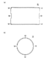
前記中間加工部材16は、元は、図5に示すように、中央帯状部16aの両側にそれぞれ側方に突出するステータ歯13を複数、本実施形態では6つずつ所定のピッチ間隔で形成した平板状の部材である。中央帯状部16aの両側のうち、一方側のステータ歯13は、他方側のステータ歯13に対しピッチ間隔の4分の1の寸法分ずれた状態に形成されている。各ステータ歯13の先端は、後述する第2の支持部材72に係合するために所定角度折り曲げられている。また、中央帯状部16aにはその中心線上に沿って4つの細長い矩形状のかしめ孔18,18,…が所定間隔毎に形成されている。
As shown in FIG. 5, the
前記中間プレート17は、図7に示すように、中心に円形状の挿入孔19を形成してなる平板状の部材である。この中間プレート17の挿入孔19の内周縁には4つのかしめ部21,21,…が円周方向に沿って90度間隔で設けられ、この各かしめ部21は、中間プレート17の挿入孔19の内周縁をL字状の溝を形成することで設けられている。また、中間プレート17の外周縁には、他の部位よりも半径方向外側に突出する4つの円弧状の突出部22,22,…が前記各かしめ部21の半径方向外側位置に形成されている。
As shown in FIG. 7, the
そして、前記中間プレートアッセンブリ15を作製するに当たっては、先ず、前記中間加工部材16を、図6に示すように、その中央帯状部16aの両端同士が繋がりかつ各ステータ歯13の先端折り曲げ側が半径方向外向きになるようにロール形状に加工する。このロール形状の中間加工部材16では、中央帯状部16aの一方側の隣接する2つのステータ歯13,13のピッチ間隔は60度であり、また、一方側のステータ歯13と他方側のステータ歯13の位相ずれは15度である。
In producing the
続いて、前記ロール形状の中間加工部材16を前記中間プレート17の挿入孔19内に挿入し、中間加工部材16の中央帯状部16aの各かしめ孔18と中間プレート17の各かしめ部21とが対向するように位置合わせを行う。その後、中間プレート17の各かしめ部21をそれぞれ対向するかしめ孔18内にかしめることで中間加工部材16の中央帯状部16aを中間プレート17に固定する。これにより、中間プレートアッセンブリ15が作製される。
Subsequently, the roll-shaped intermediate working
一方、前記各ステータブロック2の外側ステータ12は、元は、図8に示すように、鋼板等の磁性材料よりなる平板状の中間加工部材31を用いて作製される。中間加工部材31は、中心に貫通孔32を設けた円環状のリング部33と、このリング部33の外周における円周方向等間隔の6カ所から半径方向外側に向けて突出する6つの突出片34,34,…と、この各突出片34の形成位置から30度ずらした6カ所から半径方向外側に向けて突出する6つの凸状片35,35,…とを有している。
On the other hand, as shown in FIG. 8, the
そして、外側ステータ12は、図9に示すように、前記中間加工部材31を元にして、突出片34等の折り曲げ加工を施してなる。具体的には、リング部33から立設するように各突出片34をそれぞれ直角に折り曲げて前記各ステータ歯11を形成する第1の折り曲げ加工と、この各ステータ歯11の先端部をそれぞれ半径方向外側にL字状に折り曲げる第2の折り曲げ加工と、6つの凸状片35,35,…のうち、円周方向に1つ置きの3つの各凸状片35の先端を突出片34の折り曲げ方向と反対側に直角に折り曲げて係合部36を形成する第3の折り曲げ加工とを施す。
As shown in FIG. 9, the
前記各励磁コイル3は、PBT樹脂等の非磁性材料よりなるボビン41と、このボビン41の外周に巻き付けられた銅線よりなる電線42とからなる。ボビン41は、図10に示すように、両端に一対の鍔部41a,41bを有する薄肉円筒状のボビン本体41cと、一方の鍔部41aと同心状でかつこの鍔部41aより軸方向外側に突出する第1の環状突出部41dと、他方の鍔部41bと同心状でかつこの鍔部41bより軸方向外側に突出する第2の環状突出部41eとを備えており、電線42は、ボビン本体41cの外周面に巻き付けられる。第2の環状突出部41eの内径は、ボビン本体41cの内径より若干大きく設定されており、両部分41e,41cの内周面同士は、円錐面41fを介して連続するようになっている。一方、第1の環状突出部41dの内径は、ボビン本体41cの内径より一回り大きく設定されており、両部分41d,41cの内周面同士は、その間に段差を生じるようになっている。
Each
前記回転子4は、図11に示すように、インダクタ型モータ1の回転出力を取り出すための回転シャフト44と、この回転シャフト44の外周面にロータベース45を介在して回転一体に装着されたマグネット部46とを有している。マグネット部46は、回転子4の外周面を形成するものであって、N極とS極を円周方向に交互に着座して12極等配となっている。
As shown in FIG. 11, the
前記モータケース5は、一対の薄肉円筒状のケース部材51,51と、この各ケース部材51のモータ軸方向外側端にそれぞれ位置する2つの側板52,52とからなる。図12に示すように、各ケース部材51のモータ軸方向内側端には、前記中間プレート17の各突出部22に対応して、円周方向の4カ所にそれぞれ切り欠き部53が形成されており、この各切り欠き部53の深さは、中間プレート17の厚みの半分に設定されている。また、各ケース部材51のモータ軸方向外側端には、後述する側板52の各突出部59に対応して、円周方向の4カ所にそれぞれ切り欠き部54が形成されており、この各切り欠き部54の深さは、側板52の厚みと同一寸法に設定されている。
The
前記各側板52は、図13に示すように、中心に円形状の中心孔56を形成してなる平板状の部材である。この側板52の中心孔56の周囲には、前記外側ステータ12の各係合部36に対応して、円周方向の3カ所にそれぞれ係合孔57及びねじ孔58等が設けられている。また、側板52の周縁部には、他の部位よりも半径方向外側に突出する4つの円弧状の突出部59,59,…が円周方向に90度間隔で形成されているとともに、1カ所の隣接する突出部59,59間に切り欠き部60が形成されている。
As shown in FIG. 13, each
そして、インダクタ型モータ1の組立状態においては、図1及び図2に示すように、中間プレートアッセンブリ15の中間プレート17は、その各突出部22がモータケース5の一対のケース部材51,51の切り欠き部53,53間に挟まれた状態で保持されている。また、各外側ステータ12は、その各係合部36をそれぞれモータケース5の対応する側板52の係合孔57に挿入係合させることで側板52に保持されており、各側板52は、その各突出部59がモータケース5の対応するケース部材51の切り欠き部54に嵌め込まれた状態でその嵌め込み部分を溶接して固定されている。
In the assembled state of the inductor-
また、各励磁コイル3のボビン41は、その第1の環状突出部41dが前記中間プレートアッセンブリ15の中間プレート17に当接しかつ各鍔部41a,41aがモータケース51のケース部材51の内周面に接触した状態で固定されている。この各励磁コイル3の電線42にはモータケース5の一方の側板52の切り欠き部60からモータケース5内に導入したリード線61が接続されている。
Further, the
さらに、回転子4は、そのマグネット部46がステータブロック2の内周面と所定の隙間を隔てた状態でステータブロック2と同軸上に配置されており、この回転子4の回転シャフト44の両端は、それぞれモータケース5の側板52の中心孔56に軸受け62を介在して回転自在に支持されている。
Further, the
しかして、所定のシーケンスに従って2つの励磁コイル3,3に通電すると、一方のステータブロック2の外側ステータ12のステータ歯11と内側ステータ14のステータ歯13、及び他方のステータブロック2の外側ステータ12のステータ歯11と内側ステータ14のステータ歯13が各々順次N極及びS極に磁化され、この磁化されたステータ歯11,13と回転子4のマグネット部46のN極及びS極が吸引と反発を繰り返すことによって,回転子4が回転してトルクを出力するようになっている。
Thus, when the two
加えて、前記中間プレート17を挟んだその両側にはそれぞれ前記各ステータブロック2の外側ステータ12の各ステータ歯11の先端を支持する一対の第1の支持部材71,71が設けられているとともに、前記各ステータブロック2の外側ステータ12のモータケース側板52への固定箇所であるリング部33の内側にはそれぞれ前記各ステータブロック2の内側ステータ14の各ステータ歯13の先端を支持する一対の第2の支持部材72,72が設けられている。
In addition, a pair of
前記各第1の支持部材71は、図14にも示すように、POM樹脂等の非磁性材料よりなるリング状の部材であり、その内径は、励磁コイル3のボビン41のボビン本体41cの内径と同一寸法に設定され、外径は、ボビン41の第1の環状突出部41dの内径よりも若干小さく設定されている。また、第1の支持部材71の外周面には外側ステータ12の各ステータ歯11の先端が当接して係合する6つの係合溝73,73,…が円周方向に等間隔(60度間隔)に形成されている。そして、インダクタ型モータ1の組立時には、予め、図3に示すように、外側ステータ12のリング部33の係合部36を側板52の係合孔57に挿入してかしめる(図2参照)ことにより外側ステータ12と側板52を固定するとともに、この外側ステータ12内のリング部33側に第2の支持部材72を挿入しておく。続いて、外側ステータ12の各ステータ歯11の先端側を、ボビン41の第2の環状突出部41eからボビン41の内部に挿入し、これらをモータケース5の1つのケース部材51内に挿入する。しかる後、第1の支持部材71をボビン41の第1の環状突出部41dの内部に挿入した上、この第1の支持部材71の各係合溝73に外側ステータ12の各ステータ歯11の先端部を当接係合して第1の支持部材71を装着する。これにより、インダクタ型モータ1の組立状態では、図1に示す如く第1の支持部材71がボビン41の第1の環状突出部41d内に嵌まり込んだ状態に配置され、第1の支持部材71の内周面とボビン41(詳しくはボビン本体41c)の内周面とは面一になる。
As shown in FIG. 14, each of the
前記各第2の支持部材72は、図15にも示すように、POM樹脂等の非磁性材料よりなるリング状の部材であり、その外径は、第2の支持部材72が外側ステータ12のリング部33内側に嵌まり込み可能な大きさに設定されている。また、第2の支持部材72の外周面には内側ステータ14の各ステータ歯13の先端が嵌まり込んで係合する6つのU字状の係合部74,74,…が円周方向に等間隔(60度間隔)に形成されている。そして、インダクタ型モータ1の組立時には、予め、図3に示すように、第2の支持部材72を外側ステータ12のリング部33内側に第2の支持部材72の各係合部74が外側ステータ12の隣接する2つのステータ歯11,11間から露出する状態に嵌め込んだ上、前述の如く外側ステータ12の各ステータ歯11の先端部に装着した第1の支持部材71の内側から内側ステータ14の各ステータ歯13を挿入して当該各ステータ歯13の先端部を前記第2の支持部材72の各係合部74に係合するようになっている。
As shown in FIG. 15, each of the
次に、前記インダクタ型モータ1の作用効果を説明するに、2つのステータブロック2,2の内側ステータ14,14同士は、1つの中間プレートアッセンブリ15により構成され、この中間プレートアッセンブリ15は、中央帯状部16aの両側にそれぞれ側方に向けて突出するステータ歯13を6つずつ形成した磁性材料よりなる平板状の中間加工部材16を元にし、この中間加工部材16を中央帯状部16aの両端同士が繋がるようにロール形状に加工し、その後ロール形状の中間加工部材16を中間プレート17の挿入孔19内に挿入して中間加工部材16の中央帯状部16aを中間プレート17に固定することで一体的に形成されている。このため、モータ1の外径による制限を受けることなく、各内側ステータ14のステータ歯13の長さを大きくしてモータ1の出力を十分に確保することができる。
Next, the operation and effect of the
しかも、2つのステータブロック2,2内に挿入して配置される回転子4は、内側ステータ14や中間プレート17との関係から分割する必要はないので、モータ1の製造工程数を少なくして製造コストの低減化を図ることができる。
In addition, since the
特に、本実施形態では、前記各ステータブロック2の外側ステータ12は、半径方向外側に向けて突出する突出片34を円周方向に6つ形成した磁性材料よりなる平板状の中間加工部材31を元にし、前記各突出片34を直角に曲げ起こしてステータ歯11を6つ形成してなるため、モータ1の外径による制限を受けることなく、各外側ステータ12のステータ歯11の長さを、各内側ステータ14のステータ歯13の長さと同じ大きさにしてモータ1の出力を十分に確保することができる。この結果、モータ1の高出力化を確実に図ることができる。
In particular, in the present embodiment, the
また、前記各ステータブロック2の外側ステータ12の各ステータ歯11の先端が中間プレート17の両側に配置したリング状の第1の支持部材71により支持されているとともに、各ステータブロック2の内側ステータ14の各ステータ歯13の先端が外側ステータ12のモータケース側板52への固定箇所であるリング部33の内側に配置したリング状の第2の支持部材72により支持されているため、外側ステータ12及び内側ステータ14の各ステータ歯11,13の長さを長くしたことに拘わらず、各ステータ歯11,13が回転子4のマグネット部46の磁力による撓むのを抑制することができる。
The tips of the
尚、本発明は前記実施形態に限定されるものではなく、その他種々の形態を包含するものである。例えば回転子4のマグネット部46が12極からなる場合について述べたが、本発明は、これに限らず、6極や8極等,様々な極数からなるインダクタ型モータにも同様に適用することができる。
In addition, this invention is not limited to the said embodiment, A various other form is included. For example, although the case where the
また、前記実施形態では、2つの励磁コイル3,3の外周を囲繞するモータケース5を、2つの円筒状のケース部材51,51と、この各ケース部材51のモータ軸方向外側端にそれぞれ位置する2つの側板52,52とにより構成したが、本発明は、この構成に限らず、1つの円筒状のケース部材と2つの側板とにより構成したり、従来公知のその他のケース構造を用いて構成したりしてもよい。
In the embodiment, the
1 インダクタ型モータ
2 ステータブロック
3 励磁コイル
4 回転子
5 モータケース
11,13 ステータ歯(ステータ爪)
12 外側ステータ
14 内側ステータ
15 中間プレートアッセンブリ
16 中間加工部材
16a 中央帯状部
17 中間プレート
18 かしめ孔
19 挿入孔
21 かしめ部
22 突出部
31 中間加工部材
33 リング部(固定箇所)
34 突出片
41 ボビン
46 マグネット部
52 側板
71 第1の支持部材
72 第2の支持部材
DESCRIPTION OF
12
18
21
34 Projection piece
41
Claims (1)
前記2つのステータブロックの内側ステータ同士は、中央帯状部の両側にそれぞれ側方に向けて突出するステータ歯を複数形成した磁性材料よりなる平板状の中間加工部材を元にし、この中間加工部材を中央帯状部の両端同士が繋がるようにロール形状に加工し、その後ロール形状の中間加工部材を、中心に円形状の挿入孔が形成された中間プレートの挿入孔内に挿入して中間加工部材の中央帯状部を中間プレートにかしめ構造により固定することで一体的に形成されており、
前記かしめ構造は、前記中央帯状部にその中心線上に沿って所定間隔毎に形成された複数のかしめ孔と、前記中間プレートの挿入孔の内周縁に円周方向に所定角度毎に形成された複数のかしめ部とを有し、前記各かしめ孔と前記各かしめ部とがそれぞれ対向するように位置合わせをした状態で各かしめ部をそれぞれ対向するかしめ孔にかしめ得る構成になっており、
前記中間プレートの外周縁は、前記モータケースに保持されており、
前記各ステータブロックの外側ステータは、半径方向外側に向けて突出する突出片を円周方向に複数形成した磁性材料よりなる平板状の中間加工部材を元にし、前記各突出片を直角に曲げ起こして前記ステータ歯を形成してなり、この外側ステータは、前記モータケースの側板に固定されており、
前記中間プレートを挟んだその両側には、それぞれ前記各ステータブロックの外側ステータのステータ歯の先端を支持するリング状の第1の支持部材が配置されているとともに、前記各ステータブロックの外側ステータのモータケースへの固定箇所内側には、それぞれ前記各ステータブロックの内側ステータのステータ歯の先端を支持するリング状の第2の支持部材が設けられており、
前記第1の支持部材の内径は、前記励磁コイルのボビンの内径と同一寸法に設定されていて、第1の支持部材の内周面とボビンの内周面とが面一になっており、
前記各ステータブロックの外側ステータのステータ歯の先端部は、それぞれ前記第1の支持部材の外周面に当接するように半径方向外側にL字状に折り曲げられていることを特徴とするインダクタ型モータ。 Two stator blocks arranged in an axially overlapping manner, two exciting coils arranged so as to surround the outer periphery of each stator block, and coaxially arranged in the two stator blocks, N A rotor having a magnet portion formed by alternately magnetizing poles and S poles in the circumferential direction on the outer peripheral surface, and a motor case surrounding the outer periphery of the two excitation coils, An outer stator having a plurality of stator teeth provided at a predetermined angle in the circumferential direction, and a plurality of stator teeth provided at a predetermined angle in the circumferential direction disposed on the other stator block side of the outer stator. The outer stator and the inner stator are arranged to face each other so that their stator teeth are alternately meshed in the circumferential direction. In inductor motor,
The inner stators of the two stator blocks are based on a flat intermediate processing member made of a magnetic material formed with a plurality of stator teeth protruding laterally on both sides of the central belt-shaped portion. After processing into a roll shape so that both ends of the central belt-like portion are connected, the roll-shaped intermediate processing member is inserted into the insertion hole of the intermediate plate in which a circular insertion hole is formed at the center, and the intermediate processing member It is integrally formed by fixing the central strip to the intermediate plate by caulking structure ,
The caulking structure is formed at a predetermined angle in the circumferential direction at the inner peripheral edge of the insertion hole of the intermediate plate and a plurality of caulking holes formed at predetermined intervals along the center line in the central band-shaped portion. A plurality of caulking portions, each caulking portion and the respective caulking portions are positioned so as to face each other, and each caulking portion is configured to be caulked to each facing caulking hole,
The outer peripheral edge of the intermediate plate is held by the motor case ,
The outer stator of each stator block is based on a flat plate-shaped intermediate processing member made of a magnetic material in which a plurality of projecting pieces projecting outward in the radial direction are formed in the circumferential direction, and each projecting piece is bent and raised at a right angle. The stator teeth are formed, and the outer stator is fixed to the side plate of the motor case,
On both sides of the intermediate plate, ring-shaped first support members for supporting the tips of the stator teeth of the outer stators of the respective stator blocks are arranged, and the outer stators of the respective stator blocks are arranged. Ring-shaped second support members that support the tips of the stator teeth of the inner stators of the respective stator blocks are provided on the inner side of the fixing points to the motor case,
The inner diameter of the first support member is set to the same size as the inner diameter of the bobbin of the excitation coil, and the inner peripheral surface of the first support member and the inner peripheral surface of the bobbin are flush with each other.
Inductor-type motor , wherein the stator tooth tips of the outer stator of each stator block are bent in an L-shape radially outward so as to contact the outer peripheral surface of the first support member. .
Priority Applications (1)
| Application Number | Priority Date | Filing Date | Title |
|---|---|---|---|
| JP2014065124A JP5636126B1 (en) | 2014-03-27 | 2014-03-27 | Inductor type motor |
Applications Claiming Priority (1)
| Application Number | Priority Date | Filing Date | Title |
|---|---|---|---|
| JP2014065124A JP5636126B1 (en) | 2014-03-27 | 2014-03-27 | Inductor type motor |
Publications (2)
| Publication Number | Publication Date |
|---|---|
| JP5636126B1 true JP5636126B1 (en) | 2014-12-03 |
| JP2015188289A JP2015188289A (en) | 2015-10-29 |
Family
ID=52139080
Family Applications (1)
| Application Number | Title | Priority Date | Filing Date |
|---|---|---|---|
| JP2014065124A Active JP5636126B1 (en) | 2014-03-27 | 2014-03-27 | Inductor type motor |
Country Status (1)
| Country | Link |
|---|---|
| JP (1) | JP5636126B1 (en) |
Citations (2)
| Publication number | Priority date | Publication date | Assignee | Title |
|---|---|---|---|---|
| JPH0731121A (en) * | 1993-07-09 | 1995-01-31 | Hitachi Ltd | Step motor |
| JP2007336680A (en) * | 2006-06-14 | 2007-12-27 | Shinsei Seiki Co Ltd | Inductor-type motor and method of manufacturing the inductor-type motor |
-
2014
- 2014-03-27 JP JP2014065124A patent/JP5636126B1/en active Active
Patent Citations (2)
| Publication number | Priority date | Publication date | Assignee | Title |
|---|---|---|---|---|
| JPH0731121A (en) * | 1993-07-09 | 1995-01-31 | Hitachi Ltd | Step motor |
| JP2007336680A (en) * | 2006-06-14 | 2007-12-27 | Shinsei Seiki Co Ltd | Inductor-type motor and method of manufacturing the inductor-type motor |
Also Published As
| Publication number | Publication date |
|---|---|
| JP2015188289A (en) | 2015-10-29 |
Similar Documents
| Publication | Publication Date | Title |
|---|---|---|
| WO2010047098A1 (en) | Dual rotor motor and manufacturing method therefor | |
| JP5859112B2 (en) | Rotating electric machine armature and method of manufacturing rotating electric machine armature | |
| US20190148995A1 (en) | Permanent magnet synchronous machine and method for manufacturing permanent magnet synchronous machine stator | |
| JP2004215476A (en) | Combinational stator structure of motor | |
| JP6627082B2 (en) | Electric motor | |
| JP2007104819A (en) | Rotating electric machine | |
| AU2006344645B2 (en) | Inductor motor and method of manufacturing inductor motor | |
| JP2008187841A (en) | Armature core, armature, motor, and manufacturing method for armature core | |
| KR20170026218A (en) | Single phase permanent magnet motor and method for making same | |
| CN107919778B (en) | Winding method of brushless motor and stator | |
| JP2012161237A (en) | Stator of rotary electric machine and manufacturing method of the same | |
| JP5376262B2 (en) | Stator for rotating electric machine and method for manufacturing the same | |
| JP5636126B1 (en) | Inductor type motor | |
| JP5528164B2 (en) | Stator for rotating electrical machine and method for manufacturing the same | |
| JP4685516B2 (en) | Rotating electric machine armature | |
| JP2006271142A (en) | Rotary machine | |
| JP4685391B2 (en) | Rotating electrical machine armature and manufacturing method thereof | |
| JP5848097B2 (en) | Rotor and motor | |
| JP6209060B2 (en) | Inductor type motor | |
| US20140084746A1 (en) | Dc commutator motor and auxiliary machine for motor vehicle using the same | |
| JP2021044885A (en) | Manufacturing method of laminated iron core, manufacturing method of electrical machine, manufacturing apparatus of laminated iron core, and electrical machine | |
| JP2001251792A (en) | Stator core for rotating electric machine | |
| JP7203639B2 (en) | Rotating electric machine | |
| JP4760286B2 (en) | motor | |
| JP2007159262A (en) | Motor |
Legal Events
| Date | Code | Title | Description |
|---|---|---|---|
| TRDD | Decision of grant or rejection written | ||
| A01 | Written decision to grant a patent or to grant a registration (utility model) |
Free format text: JAPANESE INTERMEDIATE CODE: A01 Effective date: 20140924 |
|
| A61 | First payment of annual fees (during grant procedure) |
Free format text: JAPANESE INTERMEDIATE CODE: A61 Effective date: 20141017 |
|
| R150 | Certificate of patent or registration of utility model |
Ref document number: 5636126 Country of ref document: JP Free format text: JAPANESE INTERMEDIATE CODE: R150 |
|
| R250 | Receipt of annual fees |
Free format text: JAPANESE INTERMEDIATE CODE: R250 |
|
| R250 | Receipt of annual fees |
Free format text: JAPANESE INTERMEDIATE CODE: R250 |
|
| R250 | Receipt of annual fees |
Free format text: JAPANESE INTERMEDIATE CODE: R250 |