JP5634837B2 - Signal processing method and signal processing system - Google Patents
Signal processing method and signal processing system Download PDFInfo
- Publication number
- JP5634837B2 JP5634837B2 JP2010263484A JP2010263484A JP5634837B2 JP 5634837 B2 JP5634837 B2 JP 5634837B2 JP 2010263484 A JP2010263484 A JP 2010263484A JP 2010263484 A JP2010263484 A JP 2010263484A JP 5634837 B2 JP5634837 B2 JP 5634837B2
- Authority
- JP
- Japan
- Prior art keywords
- vibration waveform
- waveform
- signal
- mother
- correlation
- Prior art date
- Legal status (The legal status is an assumption and is not a legal conclusion. Google has not performed a legal analysis and makes no representation as to the accuracy of the status listed.)
- Expired - Fee Related
Links
Images


Landscapes
- Measuring Pulse, Heart Rate, Blood Pressure Or Blood Flow (AREA)
- Measuring And Recording Apparatus For Diagnosis (AREA)
Description
本発明は、ノイズと特定の振動波形とを含む信号の信号処理方法及び信号処理システムに関する。 The present invention relates to a signal processing method and a signal processing system for a signal including noise and a specific vibration waveform.
近年、外耳道の圧力振動を電気信号に変換して生体情報を電気信号として取得する方法が提案されている(例えば、特許文献1参照)が、生体情報は主に低周波帯域に多く存在し、特に人間の可聴周波数帯域よりも低い周波数帯域に多くの生体情報が含まれていることから、特許文献1に記載された従来技術では、ローパスフィルタを用いて生体情報の多く含まれる低周波帯域の信号を抽出している。
In recent years, there has been proposed a method for converting the pressure vibration of the external auditory canal into an electrical signal to acquire biological information as an electrical signal (see, for example, Patent Document 1), but biological information is mainly present in a low frequency band, In particular, since a large amount of biological information is included in a frequency band lower than the human audible frequency band, the conventional technique described in
しかし、生体情報が多く含まれている低周波領域には、心拍等の生体情報以外に身体を動作させた際に発生する外来ノイズを含んでいる。これらの外来ノイズは心拍信号等の生体情報と同様の周波数スペクトルを含んでいるため、ローパスフィルタでは除去することが困難で、所望の生体情報を効果的に抽出することが難しいという問題があった。特に、動作中の人間から生体情報を取得しようとする場合には、動作中の身体から発生するノイズレベルが大きくなり、生体情報を確実に抽出することが困難であるという問題があった。 However, the low-frequency region containing a large amount of biological information includes extraneous noise generated when the body is operated in addition to biological information such as heartbeats. Since these external noises contain the same frequency spectrum as biological information such as heartbeat signals, it is difficult to remove with a low-pass filter, and it is difficult to effectively extract desired biological information. . In particular, when attempting to acquire biological information from an operating person, there is a problem that the level of noise generated from the operating body increases, making it difficult to reliably extract the biological information.
そこで、本発明は、ノイズを含む信号から生体情報を効果的に取得することを目的とする。 Therefore, an object of the present invention is to effectively acquire biological information from a signal including noise.
本発明の信号処理方法は、ノイズと特定の振動波形とを含む信号の信号処理方法であって、周期又は振動の位相が異なる複数の基準振動波形を含む母基準振動波形群を生成するステップと、評価対象信号を取得するステップと、評価対象信号と前記母振動波形群の前記各基準振動波形との各相関を計算するステップと、計算した相関が最大となる最大相関基準振動波形を決定するステップと、最大相関基準振動波形に基づいて特定の振動波形の近似波形を生成するステップと、を有し、前記基準振動波形は、連続パルスとゼロ信号とからなる信号組を複数回繰り返したものであり、前記母振動波形群は、ゼロ信号の長さを異ならせて周期を異ならせた複数の異周期波形組を含み、前記各異周期波形組は、周期が同一で連続パルスの位相が異なる複数の同周期異位相波形を含むこと、を特徴とする。 The signal processing method of the present invention is a signal processing method of a signal including noise and a specific vibration waveform, and generating a mother reference vibration waveform group including a plurality of reference vibration waveforms having different periods or vibration phases; , Obtaining an evaluation target signal, calculating each correlation between the evaluation target signal and each reference vibration waveform of the mother vibration waveform group, and determining a maximum correlation reference vibration waveform that maximizes the calculated correlation a step, it possesses and generating an approximate waveform of specific vibration waveform based on the maximum correlation reference vibration waveform, and the reference vibration waveform, that a signal set consisting of a continuous pulse and a zero signal is repeated a plurality of times The mother oscillation waveform group includes a plurality of different period waveform sets having different periods by changing the length of the zero signal, and each of the different period waveform groups has the same period and the phase of the continuous pulse. Different It includes a plurality of the periods different phase waveform, characterized by.
本発明の信号処理方法において、前記異周期波形組の各基準振動波形は、同一の連続パルスと異なるゼロ信号長さによって構成されていること、としても好適である。 In the signal processing method of the present invention, it is also preferable that each reference vibration waveform of the different periodic waveform group is composed of the same continuous pulse and a different zero signal length.
本発明の信号処理方法において、評価対象信号と前記母振動波形群の各基準振動波形との各相関を計算するステップは、時間領域の前記母振動波形群の各基準振動波形を周波数領域に変換するステップと、時間領域の評価対象信号を周波数領域に変換するステップと、周波数領域に変換した各基準振動波形と周波数領域に変換した評価対象波形の相関を計算すること、としても好適である。 In the signal processing method of the present invention, the step of calculating each correlation between the evaluation target signal and each reference vibration waveform of the mother vibration waveform group converts each reference vibration waveform of the mother vibration waveform group in the time domain into a frequency domain. And calculating the correlation between the reference vibration waveform converted into the frequency domain and the evaluation target waveform converted into the frequency domain.
本発明の信号処理システムは、ノイズと特定の振動波形とを含む生体情報センサからの信号を処理する信号処理システムであって、生体情報センサの信号を取得する生体情報センサインターフェースと、周期又は振動の位相が異なる複数の基準振動波形を含む母振動波形群を格納するメモリと、メモリに格納した前記母振動波形群の前記各基準振動波形と生体情報センサからの信号との各相関を計算し、計算した相関が最大となる最大相関基準振動波形を決定し、最大相関基準振動波形に基づいて特定の振動波形の近似波形を生成するプロセッサと、を有し、前記基準振動波形は、連続パルスとゼロ信号とからなる信号組を複数回繰り返したものであり、前記母振動波形群は、ゼロ信号の長さを異ならせて周期を異ならせた複数の異周期波形組を含み、前記各異周期波形組は、周期が同一で連続パルスの位相が異なる複数の同周期異位相波形を含むことを特徴とする。
Signal processing system of the present invention is a signal processing system for processing signals from the biometric information sensor comprising a noise with a specific vibration waveform, a biological information sensor interface for acquiring a signal of the biological information sensor, periodically or vibration A memory for storing a group of oscillation patterns including a plurality of reference oscillation waveforms having different phases, and a correlation between each reference oscillation waveform of the group of oscillation waveforms stored in the memory and a signal from the biological information sensor. determines the maximum correlation reference vibration waveform calculated correlation is maximized, possess a processor for generating approximate waveform of specific vibration waveform based on the maximum correlation reference vibration waveform, and the reference vibration waveform, continuous pulse And the zero oscillation signal group is repeated a plurality of times, and the mother vibration waveform group has a plurality of different period waveforms with different periods by varying the length of the zero signal. Hints, each modified period waveform set, the period is characterized in that it comprises a plurality of the periods different phase waveforms having different phases of successive pulses at the same.
本発明は、ノイズを含む信号から生体情報を効果的に取得することができる。 The present invention can effectively acquire biological information from a signal including noise.
以下、図面を参照しながら本発明の信号処理システムの実施形態について説明する。以下の説明では、生体情報センサとして人間の外耳道の圧力振動を電気信号に変換する外耳道圧センサを用い、ノイズと特定の振動波形である心拍波形とを含む信号を処理して心拍波形の近似波形と心拍数とを出力する場合について説明する。 Hereinafter, embodiments of a signal processing system of the present invention will be described with reference to the drawings. In the following description, an external ear canal pressure sensor that converts pressure vibration of a human ear canal into an electrical signal is used as a biological information sensor, and a signal including noise and a heartbeat waveform that is a specific vibration waveform is processed to approximate the heartbeat waveform. A description will be given of the case where the heart rate is output.
図1に示すように、本実施形態の信号処理システム50は、外耳道圧センサ16からのアナログ信号をデジタル信号に変換して取得する外耳道圧センサインターフェース53と、情報を処理するプロセッサであるCPU51と、CPU51の実行するプログラムや処理するデータを格納するメモリ52と、処理した信号を外部出力装置であるディスプレイ61に出力する外部出力インターフェース54とを含むコンピュータである。メモリ52には、後で説明するCPU51で処理される母振動波形群データ55、CPU51で実行される相関計算プログラム56、最大相関基準振動波形決定プログラム57、近似波形生成プログラム58が含まれると共に演算処理を行うための演算用データ領域59が含まれている。
As shown in FIG. 1, the
図1に示すように、外耳道圧センサ16は、外耳道31に挿入される外耳道挿入部16aと外耳道31から耳殻に続く形状に合わせた形状の本体16bとから構成されている。外耳道圧センサ16の外耳道挿入部16aは、略耳穴の大きさと同様の直径の円筒で、内部に貫通孔25が設けられている。本体16bの内部には、貫通孔25がつながっている空洞26が設けられている。空洞26は、貫通孔25よりも大きな内径を持っている。そして空洞26には、外耳道31の圧力振動を電気信号に変換する振動電気変換器27が取り付けられている。振動電気変換器27は、例えば、圧電素子のようなものでも良いし、振動板の振動をマグネットによって電気信号に変換するようなものであってもよい。外耳道挿入部16aと本体16bとは樹脂などによって構成されている。
As shown in FIG. 1, the ear
外耳道圧センサ16の外耳道挿入部16aは外耳道31の中にぴったりと嵌まり込んで、外部の音が外耳道31へ侵入するのを抑制する。また、外耳道圧センサ16の本体16bは作業員の耳30の耳殻にフィットして外耳道圧センサ16の位置を安定させる。空洞26を介して外耳道挿入部16aの貫通孔25を塞いでいる振動電気変換器27は、外耳道31の中にぴったりと嵌まり込んだ外耳道挿入部16aと共に外耳道31を閉じて鼓膜32との間に閉空間37を形成する。
The external auditory
図1に示すように、鼓膜32は内耳33と外耳道31を含む外耳との境界に存在する膜であり、内耳33に通じる内耳道35から心拍音や外部ノイズなどの様々な音が鼓膜に伝達されてくる。内耳33から鼓膜32に伝達された心拍音は鼓膜32を振動させる。鼓膜32の振動は外耳道挿入部16aの貫通孔25を通って空洞26から閉空間37を形成している振動電気変換器27に伝達され電気信号に変換される。このように、振動電気変換器27は外耳道31に伝達される心拍音と様々な音ノイズとを検出して電気信号に変換して出力する。
As shown in FIG. 1, the
図2に示すように、母振動波形群は、外耳道圧センサ16を装着した人間が安静状態の際に外耳道圧センサ16で取得した電気信号91からその人間の代表的な一拍分の心拍波形を連続パルス92として抽出し、図3、図4に示すように一拍分の連続パルス92とゼロ信号93,94,95とを組み合わせて心拍数又は心拍位相の異なる複数の基準振動波形101〜301を含む振動波形群としたものであり、図1に示す信号処理システム50のメモリ52の中にデータとして格納されている。以下、図2から図5を参照して母振動波形群データ55の生成について説明する。以下の説明では、母振動波形群の生成は信号処理システム50と別の母振動波形群データ生成システム70によって生成されることとして説明するが、信号処理システム50の中で同様の処理を行ってもよい。
As shown in FIG. 2, the mother vibration waveform group includes a heartbeat waveform corresponding to one beat of a representative person from an
図2に示すように、母振動波形群データ生成システム70は、外耳道圧センサ16を装着した人間が安静状態の際に外耳道圧センサ16で取得した電気信号91からその人間の代表的な一拍分の心拍波形を連続パルス92として抽出する連続パルス抽出手段71と、抽出した連続パルス92から母振動波形群データを生成する母振動波形群生成手段72と、生成した母振動波形群データ55を格納するメモリ73とを含んでいる。母振動波形群データ生成システム70は、内部に情報を処理するCPUを含むコンピュータであり、連続パルス抽出手段71、母振動波形群生成手段72はコンピュータによって実行されるプログラムであってもよい。
As shown in FIG. 2, the mother vibration waveform group
図2に示すように、連続パルス抽出手段71は、室内のベッドに横たわって安静状態としている人間の耳に取り付けた外耳道圧センサ16からの電気信号91を取得する。人間は室内のベッドに横たわっているので、この電気信号91には人間の動作などによる外部ノイズが非常に少ない状態で人間の安静状態の心拍音が含まれている。連続パルス抽出手段71は、例えば、入力された電気信号91の自己相関を取ることによってその人間の代表的な一拍分の心拍波形を連続パルス92として抽出する。心拍数が変化した場合、その人間の一拍の心拍波形はほとんど変化せず、一拍分の連続パルス92の間隔だけが変化する場合が多い。そこで、母振動波形群生成手段72は、図3(b)に示すように、図3(a)に示す抽出した時間t1の一拍分の連続パルス92に時間t21の長さのゼロ信号93をつなげた一つの信号組を3回繰り返すようにして連続パルス92の周期が(t1+t21)で全体の信号長さが時間T1である一つの基準振動波形101を生成する。ここで、ゼロ信号93と連続パルス92との一つの信号組の時間長さ(t1+t21)は心拍の周期に相当する。また、図3(c)、図3(d)に示すように、同一の時間t1の一拍分の連続パルス92に時間t21と異なる時間t22の長さのゼロ信号94、または、時間t21,t22と異なる時間t23の長さのゼロ信号95をつなげた一つの信号組を3回繰り返すようにして連続パルス92の周期が(t1+t22)、(t1+t23)で全体の信号長さが時間T2、T3である他の基準振動波形201、301を生成する。この様にして、母振動波形群生成手段72は、一拍の心拍波形が同一で心拍数の異なる複数の波形、つまり異周期波形組となる複数の基準振動波形を生成する。
As shown in FIG. 2, the continuous pulse extraction means 71 acquires the
次に、図4に示すように、母振動波形群生成手段72は、最初に生成した基準振動波形101に基づいて周期が同一で連続パルス92の位相が異なる複数の基準振動波形102から106を生成する。各基準振動波形102から106はそれぞれ最初に生成した基準振動波形101に対して連続パルス92の時間位置が信号処理システム50の外耳道圧センサ16からの電気信号をサンプリングするサンプリング周期Δtの整数倍の時間だけずれるようにしたものである。
Next, as shown in FIG. 4, the mother vibration waveform group generation means 72 generates a plurality of
図4(a)に示すように、基準振動波形101は、時間t21の長さのゼロ信号93の後に時間t1の長さの連続パルス92が続く一組の信号組が3回繰り返されているものであり、図4(b)に示すように次の基準振動波形102は基準振動波形101からサンプリング周期Δtだけ連続パルス92の時間位置がずれており、同様に、図4(c)から図4(e)に示す基準振動波形103から105はそれぞれ基準振動波形101からサンプリング周期Δtの2倍から4倍だけ連続パルス92の時間位置がずれているものである。
As shown in FIG. 4 (a), the
図4(a)に示すようにゼロ信号93と連続パルス92との一つの信号組の時間長さ(t1+t21)は心拍の周期に相当するので、例えば、基準振動波形101が一分間に60回の心拍数に相当する場合には、(t1+t21)=60/60=1.0秒となる。そして、100Hzのサンプリング周波数でサンプリングを行った場合、サンプリング周期Δtは1/100秒となることから、(t1+t21)=60/60=1.0秒の間には100回のサンプリングが行われることとなる。図4にはこのサンプリング回数をnで示す。従って、サンプリング周期Δtずつずれた基準振動波形は、図4(a)に示すようにずれ時間がゼロの基準振動波形101からずれ時間が99=(100−1)×Δtの基準振動波形106まで全部で100種類できることとなる。このようにして母振動波形群生成手段72は、同周期異位相波形組を生成する。つまり、母振動波形群生成手段72は、ゼロ時間信号の長さを変えた異周期波形組を生成した後、それぞれの異周波波形の同周期異位相波形組を生成して母振動波形群を生成する。
As shown in FIG. 4A, the time length (t 1 + t 21 ) of one signal set of the zero
本実施形態の信号処理システム50で、一分間の心拍数が30回から180回までを測定領域とする場合には、それぞれの心拍数に応じてゼロ時間信号の長さを変えた異周期波形組を生成し、それぞれの異周波波形の同周期異位相波形組を生成する必要がある。先に説明したように、心拍数が一分間に60回でサンプリング周期が100Hzの場合には100種類の位相の異なる基準振動波形が生成される。図5には各心拍数に応じて生成される同周期異位相波形の数を示してある。たとえば、心拍数が一分間に30回の場合には、生成される同周期異位相波形の数は位相のずれが0から199×Δtまでの200種類となる。
In the
図5に示すように、母振動波形群生成手段72は、心拍数が一分間に30回の場合には、200種類、31回の場合は192種類、60回の場合には100種類、120回の場合には50種類、180回の場合は33種類の基準振動波形を生成する。
As shown in FIG. 5, the mother vibration waveform
母振動波形群生成手段72は、各基準振動波形を生成したら、各基準振動波形に連続番号を付してそのデータをメモリ73に格納する。番号のつけ方は任意であるが、例えば、一分間の心拍数とサンプリング周期Δtの何倍だけ位相がずれているかによって、心拍が一分間に30回の場合で位相のずれがゼロの場合を番号0として以下順番に番号をつけていくこととしてもよい。メモリ73に格納された母振動波形群データ55は、図1に示す信号処理システム50のメモリ52の母振動波形群データ55の中に各基準振動波形の番号と共に転送される。母振動波形群のデータ55の転送が終わると、信号処理システム50の動作が可能となる。
After generating each reference vibration waveform, the mother vibration waveform
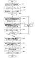
図6を参照しながら本実施形態の信号処理システム50の動作について説明する。図6のステップS101に示すように、信号処理システム50のCPU51は外耳道圧センサインターフェース53に外耳道圧センサ16からの電気信号を先に述べたサンプリング周期Δtで所定時間分だけ取得する指令を出力する。この指令によって外耳道圧センサ16の信号が取得され、取得された信号は図1に示すメモリ52に格納される。取得された信号は心拍音の信号のほかに様々な外部ノイズを含むものである。
The operation of the
図6のステップS102に示すようにCPU51はメモリ52の中のカウンタの数値Nをゼロにリセットし、図6のステップS103に示すように、CPU51は母振動波形群データ55の中からカウンタの数値N=0と同一番号の基準振動波形を読み出し、図6のステップS104に示すように相関計算プログラム56を実行してその基準振動波形と外耳道圧センサ16から取得した信号との相関を計算する。
As shown in step S102 of FIG. 6, the
相関の計算は、例えば、基準振動波形の信号をM、外耳道圧センサ16から取得した信号をSとした場合以下のように計算することとしてもよい。
C=Σ(M×S)/[(ΣM2)1/2×(ΣS2)1/2] ----- (式1)
The correlation may be calculated as follows, for example, where M is the signal of the reference vibration waveform and S is the signal acquired from the ear
C = Σ (M × S) / [(ΣM 2 ) 1/2 × (ΣS 2 ) 1/2 ] ----- (Equation 1)
相関の計算が終了したら計算した相関を基準振動波形の番号或いはカウンタの数値と共にメモリ52に格納する。相関と基準振動波形の番号とをメモリに格納したら、CPU51は、図6のステップS106に示すように、カウンタの数値Nが最終値Nend以上かどうかを判断する。そして、カウンタの数値Nが最終値Nendに達していない場合には、図6のステップS107に示すように、カウンタの数値Nを1だけ増加させて図6のステップS103に戻って次の番号の基準振動波形を読み出し、図6のステップS104に示すように外耳道圧センサ16から取得した信号との相関を計算し、図6のステップS105に示すように相関を基準振動波形の番号或いはカウンタの数値と共にメモリ52に格納する。このように、図5に示した母振動波形群に含まれる全ての基準振動波形と外耳道圧センサ16から取得した信号との相関の計算、メモリ52への格納が終わるまで図6のステップS103から図6のステップS107を繰り返す。そして、最後の番号の基準振動波形と外耳道圧センサ16から取得した信号との相関の計算、メモリ52への格納が終わると、カウンタの数値Nは基準振動波形の最後の番号のNendとなっているので、CPU51は図6のステップS106に示すように図6のステップS103から図6のステップS107の繰り返しを終了する。
When the calculation of the correlation is completed, the calculated correlation is stored in the
そして、CPU51は、図6のステップS108に示すように、メモリ52の基準振動波形の番号と共に格納した各相関を読み出し、最大相関基準振動波形決定プログラム57を実行して、その中から最大の相関を持つ基準振動波形の番号を決定する。そして、CPU51は図6のステップS109に示すように、その基準振動波形の番号からその基準振動波形が対応している心拍数を外耳道圧センサ16の検出した心拍数として出力する。また、CPU51は、図6のステップS110に示すように、近似波形生成プログラム58を実行して決定された番号の基準振動波形から心拍波形の近似波形を生成する。近似波形は、決定された番号の基準振動波形そのものでもよいし、信号処理システム50の信号処理時間分だけ連続パルス92の時間位置をずらしたものとしてもよい。生成された近似波形は、外耳道圧センサ16の検出した心拍波形として図6のステップS111に示すように、図1に示す外部出力インターフェース54からディスプレイ61に出力される。
Then, as shown in step S108 in FIG. 6, the
以上説明した様に、本実施形態の信号処理システム50は、図5に示すように検出する心拍数の範囲で対応する心拍数毎に、周期が同一で連続パルスの位相が異なる複数の同周期異位相波形を含む母振動波形群に含まれる複数の基準振動波形の中から外耳道圧センサ16から取得した電気信号と最も相関の大きい基準振動波形を決定し、その決定した基準振動波形の対応する心拍数を外耳道圧センサ16の検出した検出心拍数とし、その決定した基準振動波形に基づいて生成した心拍波形の近似波形を外耳道圧センサ16の検出した検出心拍波形として出力するものである。このため、人間が運動している場合のように外耳道圧センサ16に様々な雑音が含まれている場合でも効果的に心拍数、心拍波形を検出、表示することができる。
As described above, the
また、本実施形態では、外耳道圧センサ16からの電気信号をサンプリング周期Δtで所定時間分だけ取得し、そのデータから最大の相関を持つ基準振動波形の番号を決定することとして説明したが、外耳道圧センサ16からの電気信号を所定時間分、複数回取得し、それぞれの回毎に母振動波形群データの基準振動波形と外耳道圧センサ16から取得した信号との相関を計算し、複数回計算した相関の平均値が最大となる基準振動波形を最大の相関を持つ基準波形としてもよい。この場合、サンプリングしたデータにエラーがあった場合でも時間平均的に最大の相関を持つ基準振動波形を決定できるので、最大の相関を持つ基準振動波形の決定の際の誤差が少なくなる。
In the present embodiment, the electrical signal from the ear
本実施形態では、生体情報センサとして人間の外耳道の圧力振動を電気信号に変換する外耳道圧センサ16の信号を処理して人間の心拍波形の近似波形と心拍数とを出力する場合について説明したが、例えば、生体情報センサとして呼吸音を検出する呼吸音センサを用いて本実施形態と同様に呼吸数、呼吸波形を検出、出力するように信号処理を行うようにしてもよいし、血流音を検出する血流音センサを用いて血流音の波形を検出、出力するように構成してもよい。
In the present embodiment, a case has been described in which the signal of the external ear
次に図7から図9を用いて本発明の他の実施形態について説明する。先に図1から図6を参照して説明した実施形態と同様の部分には同様の符号を付して説明は省略する。 Next, another embodiment of the present invention will be described with reference to FIGS. Parts similar to those of the embodiment described above with reference to FIGS. 1 to 6 are denoted by the same reference numerals, and description thereof is omitted.
図7に示すように、本実施形態の信号処理システム500は、図1を参照して説明した信号処理システム50の構成に加え、メモリ52の中に外耳道圧センサ16によって検出した時間領域の信号を周波数領域の信号に変換する例えば高速フーリエ変換プログラムのような周波数変換プログラム62と、先に図3から図5を参照して説明した母振動波形群の各基準振動波形を周波数変換した周波数変換後の母振動波形群データ63と、周波数領域で外耳道圧センサ16によって検出した信号と周波数変換後の各基準振動波形との相関を計算する周波数領域の相関計算プログラム64とを更に含んでいる。
As shown in FIG. 7, the
図8に示すように、本実施形態の母振動波形群データ生成システム700は、先に図2を参照して説明した母振動波形群データ生成システム70の構成に加え、母振動波形群生成手段72によって生成した母振動波形群の各基準振動波形を周波数変換する周波数変換手段74を含み、メモリ73には周波数変換後の母振動波形群の各基準振動波形が格納される。母振動波形群データ生成システム700は、内部に情報を処理するCPUを含むコンピュータであり、連続パルス抽出手段71、母振動波形群生成手段72、周波数変換手段74はコンピュータによって実行されるプログラムであってもよい。
As shown in FIG. 8, the mother vibration waveform group
図8に示すように、連続パルス抽出手段71、母振動波形群生成手段72は、先に説明した実施形態と同様、母振動波形群生成手段72は、一拍の心拍波形が同一で心拍数の異なる複数の波形、つまり異周期波形組となる複数の基準振動波形を生成し、その後それぞれの異周波波形について同周期異位相波形組を生成して母振動波形群を生成する。周波数変換手段74は、生成した母振動波形群の時間領域の各基準振動波形を図8の符号96で示すような周波数領域のデータに変換してメモリ73に格納する。メモリ73に格納された周波数変換後の母振動波形群のデータ63は、図7に示す信号処理システム500のメモリ52の周波数変換後の母振動波形群データ63の中に各基準振動波形の番号と共に転送される。周波数変換された母振動波形群のデータ63の転送が終わると、信号処理システム500の動作が可能となる。
As shown in FIG. 8, the continuous pulse extraction means 71 and the mother vibration waveform group generation means 72 are similar to the embodiment described above. The mother vibration waveform group generation means 72 has the same heartbeat waveform for one beat and the heart rate. Are generated, that is, a plurality of reference vibration waveforms to be a different period waveform set, and then a same period different phase waveform set is generated for each different frequency waveform to generate a mother vibration waveform group. The
図9を参照しながら本実施形態の信号処理システム500の動作について説明する。図9のステップS201に示すように、信号処理システム500のCPU51は外耳道圧センサインターフェース53に外耳道圧センサ16からの電気信号を先に述べたサンプリング周期Δtで所定時間分だけ取得する指令を出力する。この指令によって外耳道圧センサ16の信号が取得され、取得された信号は図1に示すメモリ52に格納される。取得された信号は心拍音の信号のほかに様々な外部ノイズを含むものである。図9のステップS202に示すように、CPU51は、周波数変換プログラム62を実行して取得した時間領域の信号を周波数領域に変換し、図9のステップS203に示すように周波数領域に変換したデータをメモリ52に格納する。
The operation of the
図9のステップS204に示すようにCPU51はメモリ52の中のカウンタの数値Nをゼロにリセットし、図9のステップS205に示すように、CPU51は周波数変換後の母振動波形群データ63の中からカウンタの数値N=0と同一番号の周波数変換後の基準振動波形を読み出し、図9のステップS206に示すように周波数領域の相関計算プログラム64を実行して周波数変換後のその基準振動波形と外耳道圧センサ16から取得した信号の周波数変換後のデータとの相関を計算する。
As shown in step S204 of FIG. 9, the
相関の計算は、例えば、次のように行う。N番目の基準振動波形の周波数変換後のデータは、周波数をfとして実数部MRe(f)Nと虚数部MIm(f)Nとを持っている。また、外耳道圧センサ16から取得した信号の周波数変換後のデータも実数部SRe(f)と虚数部SIm(f)とを持っている。そして、N番目の基準振動波形の周波数変換後のデータと外耳道圧センサ16から取得した信号の周波数変換後のデータの実数部の相関ReNと虚数部の相関ImNはそれぞれ次のように計算する。
ReN=Σ(MRe(f)N・SRe(f))−------------- (式2)
ImN=Σ(MIm(f)N・SIm(f))−------------- (式3)
For example, the correlation is calculated as follows. The frequency-converted data of the Nth reference vibration waveform has a real part MRe (f) N and an imaginary part MIm (f) N , where the frequency is f. Further, the data obtained after frequency conversion of the signal acquired from the ear
Re N = Σ (MRe (f) N · SRe (f)) ------------- (Equation 2)
Im N = Σ (MIm (f) N · SIm (f)) -------------- (Equation 3)
実数部の相関ReNと虚数部の相関ImNの計算が終了したら計算したCPU51は図9のステップS207に示すように各相関を基準振動波形の番号或いはカウンタの数値と共にメモリ52に格納する。相関と基準振動波形の番号とをメモリに格納したら、CPU51は、図9のステップS208に示すように、カウンタの数値Nが最終値Nend以上かどうかを判断する。そして、カウンタの数値Nが最終値Nendに達していない場合には、図9のステップS209に示すように、カウンタの数値Nを1だけ増加させて図9のステップS205に戻って次の番号の基準振動波形を読み出し、図9のステップS206に示すように外耳道圧センサ16から取得した信号を周波数変換した信号と次の番号の基準振動波形の周波数領域の実数部の相関ReNと虚数部の相関ImNを計算し、図9のステップS207に示すように各相関を基準振動波形の番号或いはカウンタの数値と共にメモリ52に格納する。このように、図5に示した母振動波形群に含まれる全ての基準振動波形と外耳道圧センサ16から取得した信号との周波数領域の実数部の相関ReNと虚数部の相関ImNの計算、メモリ52への格納が終わるまで図9のステップS205から図9のステップS209を繰り返す。そして、最後の番号Nendの基準振動波形と外耳道圧センサ16から取得した信号との実数部の相関ReNendと虚数部の相関ImNendの計算、メモリ52への格納が終わると、カウンタの数値Nは基準振動波形の最後の番号のNendとなっているので、CPU51は図9のステップS208に示すように図9のステップS205から図9のステップS209の繰り返しを終了する。
CPU51 the calculation of the correlation Im N calculated when finished correlation Re N and the imaginary part of the real part is stored in the
そして、CPU51は、図9のステップS210に示すように、メモリ52の基準振動波形の番号と共に格納した各実数部の相関ReNと各虚数部の相関ImNを読み出し、最大相関基準振動波形決定プログラム57を実行して、例えば、実数部の相関ReNと虚数部の相関ImNの平均値が最大となる基準振動波形の番号を決定する。そして、CPU51は母振動波形群データ55を参照しながら図9のステップS211に示すように、その基準振動波形の番号からその基準振動波形が対応している心拍数を外耳道圧センサ16の検出した心拍数として出力する。また、CPU51は、図9のステップS212に示すように、近似波形生成プログラム58を実行して決定された番号の基準振動波形から心拍波形の近似波形を生成する。近似波形は、決定された番号の基準振動波形そのものでもよいし、信号処理システム500の信号処理時間分だけ連続パルス92の時間位置をずらしたものとしてもよい。生成された近似波形は、外耳道圧センサ16の検出した心拍波形として図9のステップS213に示すように、図7に示す外部出力インターフェース54からディスプレイ61に出力される。
Then,
以上説明した様に、本実施形態の信号処理システム500は、先に図1から図6を参照して説明した実施形態と同様の効果に加え、周波数領域で実数部の相関ReNと虚数部の相関ImNに基づいて外耳道圧センサ16によって取得した信号と最大相関を持つ基準振動波形を決定するので、先に説明した実施形態よりも効率的にノイズを除去することができるので、人間が運動している場合のように大きなノイズを含んでいる場合であってもより効果的に心拍数、心拍波形を検出、表示することができる。
As described above, the
以上説明した各実施形態では、母振動波形群は、図2、図7に示す連続パルス抽出手段71によって抽出した同一の連続パルス92に異なる時間長さのゼロ信号93,94,95を組み合わせて生成することとして説明したが、図10(b)に示すように、図10(a)に示す抽出した時間t5の一拍分の連続パルス92に時間t51の長さのゼロ信号94をつなげた一つの信号組を3回繰り返すようにして連続パルス92の周期が(t5+t51)で全体の信号長さが時間T5である一つの基準振動波形501を生成し、基準振動波形501全体を時間T5から時間T6に拡大して、拡大した時間t6の連続パルス97に拡大した時間t61の長さのゼロ信号98をつなげた一つの信号組を3回繰り返すようにして連続パルス97の周期が(t6+t61)で全体の信号長さが時間T6である他の基準振動波形601を生成して、図5の各心拍数に対応する複数の基準振動波形を生成し、図4に示したのと同様の方法で、位相をずらした複数の同周期異位相の基準振動波形を生成するようにしてもよい。
In each of the embodiments described above, the mother vibration waveform group is obtained by combining the same
本実施形態は先に説明した実施形態と同様の効果を奏する。 This embodiment has the same effects as the previously described embodiments.
16 外耳道圧センサ、16a 外耳道挿入部、16b 本体、25 貫通孔、26 空洞、27 振動電気変換器、30 耳、31 外耳道、32 鼓膜、33 内耳、35 内耳道、37 閉空間、50,500 信号処理システム、51 CPU、52,73 メモリ、53 外耳道圧センサインターフェース、54 外部出力インターフェース、55 母振動波形群データ、56 相関計算プログラム、57 最大相関基準振動波形決定プログラム、58 近似波形生成プログラム、59 演算用データ領域、61 ディスプレイ、62 周波数変換プログラム、63 周波数変換後の母振動波形群データ、64 周波数領域の相関計算プログラム、70,700 母振動波形群データ生成システム、71 連続パルス抽出手段、72 母振動波形群生成手段、74 周波数変換手段、91 電気信号、92,97 連続パルス、93,94,95,98 ゼロ信号、101〜106,201,301,501,601 基準振動波形。 16 ear canal pressure sensor, 16a ear canal insertion part, 16b body, 25 through hole, 26 cavity, 27 oscillating electrical transducer, 30 ears, 31 ear canal, 32 tympanic membrane, 33 inner ear, 35 inner ear canal, 37 closed space, 50, 500 signal Processing system, 51 CPU, 52, 73 memory, 53 ear canal pressure sensor interface, 54 external output interface, 55 mother vibration waveform group data, 56 correlation calculation program, 57 maximum correlation reference vibration waveform determination program, 58 approximate waveform generation program, 59 Data area for calculation, 61 display, 62 frequency conversion program, 63 mother vibration waveform group data after frequency conversion, 64 frequency domain correlation calculation program, 70,700 mother vibration waveform group data generation system, 71 continuous pulse extraction means, 72 Generation of mother vibration waveform group Means, 74 Frequency conversion means, 91 Electrical signal, 92, 97 continuous pulse, 93, 94, 95, 98 Zero signal, 101-106, 201, 301, 501, 601 Reference vibration waveform.
Claims (4)
周期又は振動の位相が異なる複数の基準振動波形を含む母振動波形群を生成するステップと、
評価対象信号を取得するステップと、
評価対象信号と前記母振動波形群の前記各基準振動波形との各相関を計算するステップと、
計算した相関が最大となる最大相関基準振動波形を決定するステップと、
最大相関基準振動波形に基づいて特定の振動波形の近似波形を生成するステップと、
を有し、
前記基準振動波形は、連続パルスとゼロ信号とからなる信号組を複数回繰り返したものであり、
前記母振動波形群は、ゼロ信号の長さを異ならせて周期を異ならせた複数の異周期波形組を含み、
前記各異周期波形組は、周期が同一で連続パルスの位相が異なる複数の同周期異位相波形を含むこと、
を特徴とする信号処理方法。 A signal processing method for a signal including noise and a specific vibration waveform,
Generating a mother vibration waveform group including a plurality of reference vibration waveforms having different periods or phases of vibration;
Obtaining a signal to be evaluated;
Calculating each correlation between the evaluation target signal and each reference vibration waveform of the mother vibration waveform group;
Determining a maximum correlation reference vibration waveform that maximizes the calculated correlation;
Generating an approximate waveform of a specific vibration waveform based on the maximum correlation reference vibration waveform;
I have a,
The reference vibration waveform is obtained by repeating a signal set consisting of a continuous pulse and a zero signal a plurality of times,
The mother vibration waveform group includes a plurality of different periodic waveform sets having different periods by changing the length of the zero signal,
Each of the different period waveform sets includes a plurality of same period different phase waveforms having the same period and different phases of the continuous pulse;
A signal processing method characterized by the above.
前記異周期波形組の各基準振動波形は、同一の連続パルスと異なるゼロ信号長さによって構成されていること、
を特徴とする信号処理方法。 The signal processing method according to claim 1 ,
Each reference vibration waveform of the different periodic waveform set is composed of the same continuous pulse and a different zero signal length,
A signal processing method characterized by the above.
評価対象信号と前記母振動波形群の各基準振動波形との各相関を計算するステップは、
時間領域の前記母振動波形群の各基準振動波形を周波数領域に変換するステップと、
時間領域の評価対象信号を周波数領域に変換するステップと、
周波数領域に変換した各基準振動波形と周波数領域に変換した評価対象波形の相関を計算すること、
を特徴とする信号処理方法。 The signal processing method according to claim 1 or 2 ,
The step of calculating each correlation between the evaluation target signal and each reference vibration waveform of the mother vibration waveform group includes:
Converting each reference vibration waveform of the mother vibration waveform group in the time domain into a frequency domain;
Converting a time domain evaluation target signal to a frequency domain;
Calculating the correlation between each reference vibration waveform converted to the frequency domain and the evaluation target waveform converted to the frequency domain;
A signal processing method characterized by the above.
生体情報センサの信号を取得する生体情報センサインターフェースと、
周期又は振動の位相が異なる複数の基準振動波形を含む母振動波形群を格納するメモリと、
メモリに格納した前記母振動波形群の前記各基準振動波形と生体情報センサからの信号との各相関を計算し、計算した相関が最大となる最大相関基準振動波形を決定し、最大相関基準振動波形に基づいて特定の振動波形の近似波形を生成するプロセッサと、
を有し、
前記基準振動波形は、連続パルスとゼロ信号とからなる信号組を複数回繰り返したものであり、
前記母振動波形群は、ゼロ信号の長さを異ならせて周期を異ならせた複数の異周期波形組を含み、
前記各異周期波形組は、周期が同一で連続パルスの位相が異なる複数の同周期異位相波形を含むこと、を特徴とする信号処理システム。 A signal processing system for processing a signal from a biological information sensor including noise and a specific vibration waveform,
A biological information sensor interface for acquiring a signal of the biological information sensor;
A memory for storing a mother vibration waveform group including a plurality of reference vibration waveforms having different periods or vibration phases;
Calculate the correlation between each reference vibration waveform of the mother vibration waveform group stored in the memory and the signal from the biological information sensor, determine the maximum correlation reference vibration waveform that maximizes the calculated correlation, and determine the maximum correlation reference vibration A processor that generates an approximate waveform of a specific vibration waveform based on the waveform;
I have a,
The reference vibration waveform is obtained by repeating a signal set consisting of a continuous pulse and a zero signal a plurality of times,
The mother vibration waveform group includes a plurality of different periodic waveform sets having different periods by changing the length of the zero signal,
Each of the different-period waveform sets includes a plurality of same-period different-phase waveforms having the same period and different continuous pulse phases .
Priority Applications (1)
| Application Number | Priority Date | Filing Date | Title |
|---|---|---|---|
| JP2010263484A JP5634837B2 (en) | 2010-11-26 | 2010-11-26 | Signal processing method and signal processing system |
Applications Claiming Priority (1)
| Application Number | Priority Date | Filing Date | Title |
|---|---|---|---|
| JP2010263484A JP5634837B2 (en) | 2010-11-26 | 2010-11-26 | Signal processing method and signal processing system |
Publications (2)
| Publication Number | Publication Date |
|---|---|
| JP2012110559A JP2012110559A (en) | 2012-06-14 |
| JP5634837B2 true JP5634837B2 (en) | 2014-12-03 |
Family
ID=46495452
Family Applications (1)
| Application Number | Title | Priority Date | Filing Date |
|---|---|---|---|
| JP2010263484A Expired - Fee Related JP5634837B2 (en) | 2010-11-26 | 2010-11-26 | Signal processing method and signal processing system |
Country Status (1)
| Country | Link |
|---|---|
| JP (1) | JP5634837B2 (en) |
Families Citing this family (2)
| Publication number | Priority date | Publication date | Assignee | Title |
|---|---|---|---|---|
| JP6018025B2 (en) * | 2013-07-29 | 2016-11-02 | ビフレステック株式会社 | Sample information processing device |
| JP6779291B2 (en) * | 2016-06-17 | 2020-11-04 | シチズン時計株式会社 | Detection device, information input device and watching system |
Family Cites Families (3)
| Publication number | Priority date | Publication date | Assignee | Title |
|---|---|---|---|---|
| JP4207590B2 (en) * | 2003-02-04 | 2009-01-14 | ソニー株式会社 | Receiving apparatus and synchronization processing method |
| JP2004263484A (en) * | 2003-03-03 | 2004-09-24 | Chuo Service:Kk | Coin laundry |
| JP4469746B2 (en) * | 2005-03-29 | 2010-05-26 | 株式会社東芝 | Heart rate measuring device and method of operating heart rate measuring device |
-
2010
- 2010-11-26 JP JP2010263484A patent/JP5634837B2/en not_active Expired - Fee Related
Also Published As
| Publication number | Publication date |
|---|---|
| JP2012110559A (en) | 2012-06-14 |
Similar Documents
| Publication | Publication Date | Title |
|---|---|---|
| CN108354612B (en) | Signal processing method and device | |
| EP3742965B1 (en) | Measuring respiration with an in-ear accelerometer | |
| Hsu et al. | Skin-coupled personal wearable ambulatory pulse wave velocity monitoring system using microelectromechanical sensors | |
| CN107874745B (en) | Temperature rhythm obtaining equipment and method and wearable device | |
| JP2007007075A (en) | Blood pressure measurement device | |
| KR20140060737A (en) | Device of transmitting a bio signal, device of receiving the bio signal, and method thereof | |
| JP2001198094A (en) | Pulse rate detector | |
| JP5634837B2 (en) | Signal processing method and signal processing system | |
| JP5528850B2 (en) | Mobile terminal device, stress estimation system, operation method, stress estimation program | |
| JP6491920B2 (en) | Biological signal processing apparatus and biological signal processing method | |
| CN113425276A (en) | Heart rate monitoring method, earphone and computer storage medium | |
| WO2019049667A1 (en) | Heartbeat detection device, heartbeat detection method, and program | |
| JP2016182165A (en) | Biological signal processing device, biological signal processing program, computer readable recording medium recording biological signal processing program and biological signal processing method | |
| JP2014036800A (en) | Living body motion information detection device | |
| KR20200064744A (en) | Non contact blood pressure measuring method and apparatus using video | |
| JP2009112596A (en) | Biological information detecting apparatus | |
| KR20150097167A (en) | An electrocardiogram (ecg) sensor and a method of operating the same | |
| JP7051786B2 (en) | Autonomous full spectrum biomonitoring | |
| CN113892913A (en) | Prompt message generation method and device, electronic equipment and storage medium | |
| US20110298620A1 (en) | System, method and device for auditory representation of rhythmical parameters | |
| JP7089650B2 (en) | Processing equipment, systems, processing methods, and programs | |
| JP2011104113A (en) | Respiration estimating device, respiration estimating method, and respiration estimating program | |
| JP5836225B2 (en) | Living body presence / absence detection device | |
| JP2010187842A (en) | Heart rate measurement device and head set with heart rate measurement function | |
| JP7366404B2 (en) | Breathing rate calculation device, breathing rate calculation method, and program |
Legal Events
| Date | Code | Title | Description |
|---|---|---|---|
| A621 | Written request for application examination |
Free format text: JAPANESE INTERMEDIATE CODE: A621 Effective date: 20131108 |
|
| A977 | Report on retrieval |
Free format text: JAPANESE INTERMEDIATE CODE: A971007 Effective date: 20140326 |
|
| A131 | Notification of reasons for refusal |
Free format text: JAPANESE INTERMEDIATE CODE: A131 Effective date: 20140422 |
|
| A131 | Notification of reasons for refusal |
Free format text: JAPANESE INTERMEDIATE CODE: A131 Effective date: 20140708 |
|
| A521 | Written amendment |
Free format text: JAPANESE INTERMEDIATE CODE: A523 Effective date: 20140902 |
|
| A01 | Written decision to grant a patent or to grant a registration (utility model) |
Free format text: JAPANESE INTERMEDIATE CODE: A01 Effective date: 20140930 |
|
| A61 | First payment of annual fees (during grant procedure) |
Free format text: JAPANESE INTERMEDIATE CODE: A61 Effective date: 20141015 |
|
| LAPS | Cancellation because of no payment of annual fees |