JP5629332B2 - Device for introducing air and / or sealant into a tire - Google Patents
Device for introducing air and / or sealant into a tire Download PDFInfo
- Publication number
- JP5629332B2 JP5629332B2 JP2012555333A JP2012555333A JP5629332B2 JP 5629332 B2 JP5629332 B2 JP 5629332B2 JP 2012555333 A JP2012555333 A JP 2012555333A JP 2012555333 A JP2012555333 A JP 2012555333A JP 5629332 B2 JP5629332 B2 JP 5629332B2
- Authority
- JP
- Japan
- Prior art keywords
- container
- hose
- outlet
- inlet
- coupling
- Prior art date
- Legal status (The legal status is an assumption and is not a legal conclusion. Google has not performed a legal analysis and makes no representation as to the accuracy of the status listed.)
- Active
Links
- 239000000565 sealant Substances 0.000 title claims description 29
- 230000008878 coupling Effects 0.000 claims description 44
- 238000010168 coupling process Methods 0.000 claims description 44
- 238000005859 coupling reaction Methods 0.000 claims description 44
- 238000007789 sealing Methods 0.000 claims description 11
- 239000012528 membrane Substances 0.000 claims description 7
- NJPPVKZQTLUDBO-UHFFFAOYSA-N novaluron Chemical compound C1=C(Cl)C(OC(F)(F)C(OC(F)(F)F)F)=CC=C1NC(=O)NC(=O)C1=C(F)C=CC=C1F NJPPVKZQTLUDBO-UHFFFAOYSA-N 0.000 claims description 4
- 238000000605 extraction Methods 0.000 claims description 3
- 230000004913 activation Effects 0.000 description 2
- 238000000926 separation method Methods 0.000 description 2
- 239000000443 aerosol Substances 0.000 description 1
- 235000019504 cigarettes Nutrition 0.000 description 1
- 238000010276 construction Methods 0.000 description 1
- 230000002950 deficient Effects 0.000 description 1
- 230000001419 dependent effect Effects 0.000 description 1
- 230000007613 environmental effect Effects 0.000 description 1
- 238000004519 manufacturing process Methods 0.000 description 1
- 239000000463 material Substances 0.000 description 1
- 230000037303 wrinkles Effects 0.000 description 1
Images


Classifications
-
- B—PERFORMING OPERATIONS; TRANSPORTING
- B29—WORKING OF PLASTICS; WORKING OF SUBSTANCES IN A PLASTIC STATE IN GENERAL
- B29C—SHAPING OR JOINING OF PLASTICS; SHAPING OF MATERIAL IN A PLASTIC STATE, NOT OTHERWISE PROVIDED FOR; AFTER-TREATMENT OF THE SHAPED PRODUCTS, e.g. REPAIRING
- B29C73/00—Repairing of articles made from plastics or substances in a plastic state, e.g. of articles shaped or produced by using techniques covered by this subclass or subclass B29D
- B29C73/16—Auto-repairing or self-sealing arrangements or agents
- B29C73/166—Devices or methods for introducing sealing compositions into articles
-
- B—PERFORMING OPERATIONS; TRANSPORTING
- B60—VEHICLES IN GENERAL
- B60C—VEHICLE TYRES; TYRE INFLATION; TYRE CHANGING; CONNECTING VALVES TO INFLATABLE ELASTIC BODIES IN GENERAL; DEVICES OR ARRANGEMENTS RELATED TO TYRES
- B60C23/00—Devices for measuring, signalling, controlling, or distributing tyre pressure or temperature, specially adapted for mounting on vehicles; Arrangement of tyre inflating devices on vehicles, e.g. of pumps or of tanks; Tyre cooling arrangements
- B60C23/10—Arrangement of tyre-inflating pumps mounted on vehicles
-
- B—PERFORMING OPERATIONS; TRANSPORTING
- B29—WORKING OF PLASTICS; WORKING OF SUBSTANCES IN A PLASTIC STATE IN GENERAL
- B29L—INDEXING SCHEME ASSOCIATED WITH SUBCLASS B29C, RELATING TO PARTICULAR ARTICLES
- B29L2030/00—Pneumatic or solid tyres or parts thereof
Landscapes
- Engineering & Computer Science (AREA)
- Mechanical Engineering (AREA)
Description
本発明は、空気及び/又はシーラントをタイヤ、とりわけ自動車タイヤに導入する装置であって、出口端を被充填タイヤに接続し得るホースの入口端に接続し得る出口及び入口を有するシーラント用容器、及び、該容器の入口または被充填タイヤに接続し得る出口端を有するホースの入口端に、選択的に接続し得る圧力発生手段、とりわけ電動ポンプすなわちコンプレッサーを具えるものに関する。 The present invention relates to a device for introducing air and / or sealant into a tire, in particular a motor vehicle tire, a sealant container having an outlet and an inlet that can be connected to the inlet end of a hose that can be connected to the filled tire. And a pressure generating means, particularly an electric pump or compressor, which can be selectively connected to the inlet of the vessel or the inlet of a hose having an outlet which can be connected to a filled tire.
そのような装置は、スペアーホイールの代替として所謂パンクキットとして、自動車に携行できる。パンクキットは、タイヤを膨張するためだけにも、またタイヤをシールしそして実質的に膨張するためにも使用できる。この点に関して、例えば、切り替えバルブ手段によって、圧力発生手段を容器の入口またはホースの入口端に選択的に接続することができる。タイヤを単に膨張するだけか、あるいは、シールしかつ膨張するのかに応じて、容器に接続されたホースまたは圧力発生手段に接続されたホースが、ユーザーによって、タイヤのバルブに接続される。 Such a device can be carried in an automobile as a so-called punk kit as an alternative to a spare wheel. The puncture kit can be used not only to inflate the tire but also to seal and substantially inflate the tire. In this regard, the pressure generating means can be selectively connected to the inlet of the vessel or the inlet end of the hose, for example by means of a switching valve means. Depending on whether the tire is simply inflated or sealed and inflated, the hose connected to the container or the hose connected to the pressure generating means is connected by the user to the tire valve.
この点に関して、ユーザーは、切り替えバルブを正しい位置に設定し、それと同時に正しいホース、即ち空気送りホースまたはシーラントホースをタイヤに接続しなければならないという面倒な問題がある。また、切り替えバルブを設けることは、コストがかかり、また構造的スペースをさらに必要とする。US−A−4765367は、コンプレッサー、またはエアロゾルタイプのシーラント容器に選択的に接続し得るホースを具えるタイヤ修理キットを開示している。そして、この2つの接続モード間を切り替える切り替えバルブが使用されている。
In this regard, the user has the trouble of having to set the switching valve in the correct position and at the same time connect the correct hose, i.e. the air feed hose or sealant hose, to the tire. Also, providing a switching valve is costly and requires additional structural space. US-A-4765367 discloses a tire repair kit comprising a hose that can be selectively connected to a compressor or aerosol type sealant container. And the switching valve which switches between these two connection modes is used.
この種の装置の取り扱いを改善し、そしてその構造をシンプルにする必要がある。
There is a need to improve the handling of this type of device and to simplify its construction.
この目的は、請求項1の特徴を具える装置によって充足される。 This object is met by a device comprising the features of claim 1.
本発明に従うと、同一のホースが、圧力発生手段と被充填タイヤとの間、また容器の出口と被充填タイヤとの間の接続のために準備され、圧力発生手段、容器の入口、容器の出口、および、ホースの入口端に、それぞれのカップリングが設けられ、これによって、ホースの入口端が圧力発生手段に直接接続される、または容器の入口が圧力発生手段に接続されかつホースの入口端が容器の出口に接続されることが選択的に可能となる。 According to the invention, the same hose is prepared for the connection between the pressure generating means and the filled tire and between the outlet of the container and the filled tire, the pressure generating means, the container inlet, the container Respective couplings are provided at the outlet and at the inlet end of the hose so that the inlet end of the hose is connected directly to the pressure generating means or the inlet of the container is connected to the pressure generating means and the hose inlet It is optionally possible to connect the end to the outlet of the container.
圧力発生手段と容器とホースとを、互いに交互に結合しそしてそれらを互いに切り離すことができるので、装置は2つの異なった接続形態を提供する。そしてその接続形態に応じて、容器を経ること無く圧力発生手段からホースへの直接的空気貫流、または結果として容器からホースへのシーラントの取り出しが生じる容器への空気供給が行われる。直接的空気貫流によって、圧縮空気がシーラント無しでホースの出口端から放出され、この接続形態の装置は純粋にタイヤの膨張のために使用できる。圧力発生手段から送られて容器を経る空気流れによって、シーラントは、容器を出てホースへと促される。この接続形態の装置は、不具合のあるタイヤのシーリング、そしてそれに続く膨張のために使用できる。 Since the pressure generating means, the container and the hose can be alternately connected to each other and disconnected from each other, the device provides two different connections. And depending on the connection form, air is directly supplied from the pressure generating means to the hose without passing through the container, or as a result, air is supplied to the container where the sealant is taken out from the container to the hose. By direct air flow, compressed air is released from the outlet end of the hose without a sealant, and this connected device can be used purely for tire inflation. The sealant is forced out of the container and into the hose by the air flow sent from the pressure generating means and through the container. This connected configuration device can be used for sealing defective tires and subsequent inflation.
装置の操作性は、カップリングによって容易になる。何故なら、ユーザーは、希望する操作モード"膨張のみ"または"シーリングと膨張"を、相当する装置構成要素を直感的に連結することで決定し得る。特にユーザーは、切り替えバルブの操作に注意する必要も、2本のホースから正しいものを選択する必要もない。両方の操作モードのために1本の同一のホースが使用され、さらに切り替えバルブが必要無いので、材料、重量、製造コストの節約となり、よってまた環境への影響の減少となる。また特に、装置はより省スペースに設計することができ、それは自動車への搭載に関して特に重要なことである。また、それぞれの装置構成要素が連結可能なことにより、使用による交換部品は、再使用できない部品、即ち例えば容器に限定されるという利点がある。同様に、シーラントの保存寿命の終了後、過剰にホースをも交換することなく、容器だけを交換できる。 The operability of the device is facilitated by the coupling. This is because the user can determine the desired mode of operation "expansion only" or "sealing and expansion" by intuitively connecting the corresponding device components. In particular, the user does not need to pay attention to the operation of the switching valve or to select the correct one from the two hoses. One identical hose is used for both modes of operation and no switching valve is required, saving material, weight and manufacturing costs, and thus reducing environmental impact. In particular, the device can be designed to be more space-saving, which is particularly important with respect to mounting in automobiles. Further, since each device component can be connected, there is an advantage that replacement parts due to use are limited to parts that cannot be reused, that is, containers, for example. Similarly, after the sealant shelf life is over, only the container can be replaced without excessively replacing the hose.
圧力発生手段を容器の入口に接続するため、また容器の出口をホースの入口端に接続するために、同一のカップリングが好ましく設けられる。従って、容器とホースの両方を、圧力発生手段に連結することが可能となる。従って、圧力発生手段の接続は、同一のカップリングによって多目的接続として構成される。 The same coupling is preferably provided for connecting the pressure generating means to the inlet of the container and for connecting the outlet of the container to the inlet end of the hose. Accordingly, both the container and the hose can be connected to the pressure generating means. Therefore, the connection of the pressure generating means is constituted as a multipurpose connection by the same coupling.
カップリングは、好ましくは、差し込み接続式のカップリングとして形成される。これは、特に簡単な操作性を可能とする。2つの接続形態の間の変更は非常に素早く行うことができ、パンクの場合これは特に重要である。カップリングは、しかし、通常、ねじ込み接続式やクランプ接続式とすることもできる。 The coupling is preferably formed as a bayonet coupling. This enables a particularly simple operability. Changes between the two topologies can be made very quickly, which is particularly important in the case of punctures. The coupling, however, can usually also be a screw connection type or a clamp connection type.
一実施例によると、圧力発生手段の、容器の入口の、容器の出口の、またホースの入口端の各接続スタブは、差し込み接続のためのプラグまたはソケットである。この場合、特に簡単な構造とし得る。 According to one embodiment, each connection stub of the pressure generating means, at the inlet of the container, at the outlet of the container and at the inlet end of the hose is a plug or socket for a bayonet connection. In this case, a particularly simple structure can be obtained.
とりわけ、カップリングプラグは、ホースの入口端に設けることができ、それは、圧力発生手段にある適合するカップリングソケットまたは容器の出口にある適合するカップリングソケットに選択的に差し込むことができる。本実施例では、さらにカップリングプラグが容器の入口に設けられており、それは同様に圧力発生手段のカップリングソケットに差し込むことができる。通常各用途において、結合のために、あるプラグをあるソケットに差し込むべきかどうか、或いはあるソケットをあるプラグに押し付けるべきかどうかという点が問題である。 In particular, a coupling plug can be provided at the inlet end of the hose, which can be selectively plugged into a matching coupling socket at the pressure generating means or a matching coupling socket at the outlet of the container. In this embodiment, a coupling plug is further provided at the inlet of the container, which can likewise be inserted into the coupling socket of the pressure generating means. Usually, in each application, the question is whether to plug a plug into a socket or to press a socket against a plug for coupling.
差し込み接続のシーリングのために、O−リングをカップリングに設けることができる。これによって、比較的高圧の空気は、圧力発生手段から容器へ及び/又はホースへ容易に導かれる。 An O-ring can be provided in the coupling for plug-in sealing. Thereby, relatively high pressure air is easily guided from the pressure generating means to the container and / or to the hose.
またさらに、カップリングを連結状態でラッチし得るロック装置を設けることができる。ロック装置は、各カップリング構成部品に直接設ける、または対応する装置構成要素のハウジングに設けることができる。各カップリング構成部品のラッチ/アンラッチのために、例えば、バイオネットクロージャーを設けることができる。ロック装置によって、互いに結合した装置構成要素の不用意な分離が防止できる。 Furthermore, a locking device that can latch the coupling in a connected state can be provided. The locking device can be provided directly on each coupling component or on the housing of the corresponding device component. For example, a bayonet closure can be provided for latching / unlatching of each coupling component. The locking device prevents inadvertent separation of the device components coupled to each other.
ホースが接続されていない時に容器の出口を閉じる安全弁、または、穴を開けることができる膜を、該出口に設けることができる。それによって、例えば容器の出口にホースが接続されていないにもかかわらず、圧力発生手段のスイッチを偶発的に作動させた場合のように、無用にシーラントが出口から放出されることを防ぎ得る。ホースを介してシールすべきタイヤへ、シーラントを分与することを可能とするために、ホースを容器の出口に連結することで、安全弁が開くように設計することができる。このために、ホースの入口端において、カップリングを特別な様式で設計することができる。とりわけ、カップリングプラグは、ホースの入口端に、開き棒を有し得る。これは、ホースを容器へ連結することによって、安全弁の閉塞要素を開放位置まで押圧する。またホースの入口端の開き棒は、装置の輸送状態における容器の出口をシールする膜に穴を開ける働きをする。 A safety valve that closes the outlet of the container when the hose is not connected, or a membrane that can be pierced, can be provided at the outlet. Thereby, it is possible to prevent the sealant from being discharged unnecessarily from the outlet, for example, when the switch of the pressure generating means is accidentally activated even though the hose is not connected to the outlet of the container. In order to allow the sealant to be dispensed through the hose to the tire to be sealed, the safety valve can be designed to open by connecting the hose to the container outlet. For this purpose, the coupling can be designed in a special manner at the inlet end of the hose. In particular, the coupling plug may have an open bar at the inlet end of the hose. This pushes the closure element of the safety valve to the open position by connecting the hose to the container. The opening bar at the inlet end of the hose serves to make a hole in the membrane that seals the outlet of the container in the transport state of the device.
本発明の一実施例によると、取り出しユニットが設けられる。これは好ましくは容器に結合解除可能なように結合され、これはとりわけ容器に螺着でき、これは入口用と出口用のカップリングとして形成されたそれぞれの支持スタブを有する。従って、取り出しユニットは、圧縮空気の供給のための接続スタブ、またさらに、容器からシーラントを取り出すための接続スタブを有し得る。そして、接続スタブに直接カップリングが設けられる。例えば、空になった容器を取り出しユニットからねじって外し、充てんされた容器をねじって取り付けるというように、空になった容器は簡単かつ迅速に交換できる。 According to one embodiment of the invention, a take-out unit is provided. This is preferably releasably connected to the container, which can inter alia be screwed to the container, which has respective support stubs formed as inlet and outlet couplings. Thus, the removal unit may have a connection stub for supplying compressed air and also a connection stub for removing the sealant from the container. A coupling is provided directly on the connection stub. For example, empty containers can be easily and quickly replaced by unscrewing the empty containers from the pick-up unit and twisting and filling the filled containers.
さらなる実施例に従うと、取り出しユニットのハウジングにおいて、容器の出口用の接続スタブは、容器の入口用の接続スタブに対して180度位置ずれしている。これは、取り出しユニット付の容器を、圧力発生手段とホースとの間に簡単に連結できるという利点を有する。 According to a further embodiment, in the housing of the removal unit, the connection stub for the container outlet is offset by 180 degrees relative to the connection stub for the container inlet. This has the advantage that the container with the take-out unit can be simply connected between the pressure generating means and the hose.
取り出しユニットは、好ましくは装置の使用姿勢において、容器の下端に配される。それによって、容器を可能な限り完全に空にすることが容易となる。装置の使用姿勢において、容器は、その一側に配することができる。容器をその一側に配した場合に、完全に空にし得る能力を確保すために、その出口を、使用姿勢における容器の底より下に位置させることができる。容器は、しかし、好ましくは取り出し位置において、逆さまに配される。 The take-out unit is preferably arranged at the lower end of the container in the usage posture of the apparatus. This makes it easy to empty the container as completely as possible. In the use posture of the device, the container can be arranged on one side thereof. To ensure the ability to be completely emptied when the container is placed on one side, its outlet can be located below the bottom of the container in the use position. The container is however arranged upside down, preferably in the removal position.
ホースの入口端にあるカップリングは、蓄圧器または圧力調整システムへの接続用に形成できる。これによって、本装置の柔軟性がさらに増す。 A coupling at the inlet end of the hose can be formed for connection to a pressure accumulator or pressure regulation system. This further increases the flexibility of the device.
さらなる実施例に従うと、装置構成要素の少なくとも一部を収容するためのハウジングが設けられる。例えば、ハウジングは、自動車のトランクルーム内の容易にアクセス可能な場所に収容できる。またハウジングは、通常、装置の使用姿勢において、その一側に配しうる。 According to a further embodiment, a housing is provided for housing at least some of the device components. For example, the housing can be housed in an easily accessible location within a car trunk room. In addition, the housing can be usually arranged on one side of the apparatus in the use posture.
またさらに、ハウジングは、容器の台座を形成しうる。従って、装置を使用するために、ハウジングを単に床に置くだけで、容器は、正しい使用位置になる。そのような台座への容器の確実な取り付けを確保するために、ハウジングの一側に、容器に結合した取り出しユニットを差し込みうる切欠きを設けることができる。 Still further, the housing may form a pedestal for the container. Thus, to use the device, simply place the housing on the floor and the container is in the correct use position. In order to ensure the reliable attachment of the container to such a pedestal, a notch into which a take-out unit coupled to the container can be inserted can be provided on one side of the housing.
さらに、本発明の実施例は、従属クレーム、記述、添付図面から理解できる。 Furthermore, embodiments of the invention can be understood from the dependent claims, the description and the attached drawings.
以下、本発明を、図面と実施例とを参照して説明する。
図1は、使用姿勢に配された本発明の装置10を示し、装置は、コンプレッサーユニット(ここでは見えない)を有するハウジング12と、シーラントを具える容器14と、ホース20とを含む。コンプレッサーユニットは、図では見えないが、環境大気を加圧するためのコンプレッサーと、コンプレッサーの駆動部としての電気モーターとを含み得る。コンプレッサーユニットはさらに、図2および3に示すように、コンプレッサーが発生する空気圧を表示する圧力計を具える。コンプレッサーユニットには、例えば、自動車のシガーライターから、図示されない電気的接続ケーブルで、電気エネルギーが供給され得る。
The present invention will be described below with reference to the drawings and examples.
FIG. 1 shows the
ホース2は、入口端24と出口端26とを有し、出口端26は、ホース20をタイヤバルブに接続するための、例えば所謂VG8ねじ込み接続するための、対応する接続部28を有する。
The hose 2 has an
容器14は、入口と出口とを有する。図1に示す第1の接続形態では、以下でより詳細に説明するように、容器14の入口はコンプレッサーに接続され、容器14の出口はホース20に接続される。例えばスイッチ操作によるコンプレッサーの起動により、シーラントは、容器14からシールすべきタイヤ内へ導入され得る。容器14が空になった後は、そのままでタイヤを直接膨張させ得る。
The
図2は、第2の接続形態にある装置10を示す。
この接続形態では、容器14を例えば横に退けて、ホース20が直接コンプレッサーに接続される。従って、圧縮空気は被充填タイヤに導入され得る。これはシーラントが付加されない本質的にそのままである。すなわち、圧力計22を使用してタイヤの充填レベルがチェックできるだけである。
FIG. 2 shows the
In this connection configuration, the
図3に、コンプレッサーユニット付のハウジング12が、容器14とホース20無しで示されている。容器14とホース20の取り外しは、例えば、タイヤへシーラントを導入した後や容器14内のシーラントの保存寿命がきたときに、新しい容器と必要に応じて新しいホースとを与えるために、行うことができる。
In FIG. 3, the
第1と第2の接続形態を切り替えるために、以下で図4〜7を参照してより正確に説明するように、コンプレッサー、容器14、ホース20は、交互に互いに連結したり互いに切り離したりできる。
In order to switch between the first and second connection configurations, the compressor, the
容器14の入口と出口(それらは容器の首部分によって容易に実現され得る)は何れも、取り出しユニット30内へ開口している。取り出しユニット30は、使用姿勢において下に位置する容器14の端に螺着され、シーラントの取り出しに際して容器14を完全に空にすることを容易とするため容器は上下逆に配される。取り出しユニット30は、互いに180度位置ずれしてハウジング34に配される入口接続スタブ36と出口接続スタブ38とを有するハウジング34を含む。入口接続スタブ36は、差し込み接続式のカップリングプラグ37として形成され、出口接続スタブ38は、差し込み接続式のカップリングソケット39として形成される。コンプレッサーはさらに、差し込み接続式のカップリングソケット39として形成されたコンプレッサー接続スタブ32を具える。さらにカップリングプラグ37として形成されたホース接続スタブ40が、ホース20の入口端24に取り付けられる。
Both the inlet and outlet of the container 14 (which can be easily realized by the neck portion of the container) open into the
取り出しユニット30の入口接続スタブ36は、コンプレッサー接続スタブ32に差し込みでき、入口接続スタブ36に設けられた第1のO−リング42は接続の理想的なシーリングを提供する。ホース接続スタブ40も同様に取り出しユニット30の出口接続スタブ38に差し込みでき、ホース接続スタブ40に設けられた第2のO−リング44は接続の理想的なシーリングを提供する。装置10が第1の接続形態での運用の準備が整った状態で、取り出しユニット30の入口接続スタブ36が、コンプレッサー接続スタブ32に差し込まれ、ホース接続スタブ40が、取り出しユニット30の出口接続スタブ38に差し込まれる。この状態で、カップリングプラグ37とカップリングソケット39との相互回転による偶発的な分離に対して、各差し込み接続は確保され得る。そのために、コンプレッサー接続スタブ32と取り出しユニット30の出口接続スタブ38とに、角のある溝46が設けられ、そして、その溝に、ホース接続スタブ40の対応する止めピン48が係合し得る。
The
またさらに、好ましくは弾力性のあるラッチフック60が、取り出しユニット30のハウジング34から突出し、装置10のハウジング12に設けた凹部62に係合でき、従って取り出しユニット30をハウジング12に固定し得る。ハウジング12の一側面に設けられた切欠き70は、コンプレッサー接続スタブ32へのアクセスを可能とし、また取り出しユニット30をハウジング12の少なくとも一部で受ける役目を果たし、従って容器14と台座の役目を果たすハウジング12との間の接続をさらに安定なものとする。取り出しユニット30がハウジング12に取り付けられる場合、入口接続スタブ36はコンプレッサー接続スタブ32に差し込まれ、ラッチフック60は凹部62に係合し、切欠き70のへりは取り出しユニット30のハウジング34の一部と係合し、全体として、ハウジング12への取り出しユニット30の、従って容器14の、非常に信頼性のある取り付けが可能となる。
Still further, a preferably
取り出しユニット30は、前記入口接続スタブ36及び出口接続スタブ38のそばにある容器出口接続スタブ50と、容器入口接続スタブ49とを有する。容器入口接続スタブ49と容器出口接続スタブ50とは、取り出しユニット30のハウジング34に、入口接続スタブ36と出口接続スタブ38とに対して90度ずれて配され、一方が他方に入れ子状態となって同軸に延びている。容器入口スタブ49と同軸で雌ねじ54を有するジャケット52が、ハウジング34を、容器14の対応する雄ねじ部にネジ止めする役目を果たす。ハウジング34が容器14にネジ止めされた時、容器入口接続スタブ49と容器出口接続スタブ50の両方が、容器14の内部に接続される。この点に関して、容器14は、容器入口接続スタブ49と連通する入口と、該入口とは分離し容器出口接続スタブ50と連通する出口とを有し得る。またあるいは、容器14は、ハウジング34が螺着された場合、容器入口接続スタブ49と容器出口接続スタブ50の両方が開口する1つの開口部(従ってそれは同時に入口と出口としての役目を果たす)を有し得る。そのような形態では、従って容器14の入口は、容器14の出口と同一である。
The take-out
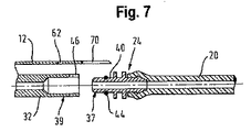
装置10の2つのカップリングプラグ37は同一設計のものなので、そしてまた、2つのカップリングソケット39も同一設計のものなので、ホース接続スタブ40は、取り出しユニット30の出口接続スタブ38だけではなく、必要に応じて、コンプレッサー接続スタブ32にも差し込むことができる。従って、コンプレッサーにより発生した圧縮空気をシーラントを加えること無くタイヤへ導くために、ホース20を直接コンプレッサーに連結できる。これは、図6および7に示す第2の接続形態に対応する。
Since the two coupling plugs 37 of the
電気モーターの起動の後、コンプレッサーは、接続形態に応じて、直接的にまたは容器14を介在する、ホース20に向けた空気流れをその出口に発生する。空気流れがまず最初に容器14に入る場合、それによって生じる容器14内の圧力増加によって、まずシーラントが、出口接続スタブ38とホース20とを経て、ホース20の出口端26に接続されている漏れを起こしているタイヤに、該タイヤをシールするために、吹き込まれる。続いて、タイヤは、空気で、所定のタイヤ圧にするために、膨張され得る。一方、ホース20がコンプレッサーに直接接続されている場合、ホース20の出口端26に接続されているタイヤは、シーラント供給無しの空気で膨張され得る。
After activation of the electric motor, the compressor generates an air flow at its outlet towards the
接続形態に応じて、修理すべきタイヤは、シーラントと空気とが充填され、また、正常に機能するタイヤは、コンプレッサーからの空気で直接膨張され得る。このように、損傷のないタイヤの膨張、または漏れを起こしているタイヤのシーリングは、1本の同一のホース20を用いて行われる。そして、ユーザーがしなければならないのは、装置を運転する前に、カップリングプラグ37とカップリングソケット39とを用いて、容器14を取り出しユニット30に、そしてコンプレッサーと、ホース20の出口端26とを正しくつなぐことだけである。
Depending on the connection configuration, the tire to be repaired is filled with sealant and air, and a normally functioning tire can be directly inflated with air from the compressor. Thus, inflation of an undamaged tire or sealing of a leaking tire is performed using one and the
この点に関して、ホース20を直接コンプレッサーに連結するか、もしくはその間に取り出しユニット30付きの容器14を連結するかが、基本的な問題であるので、不正確な使用によるリスクは比較的小さい。
In this regard, the risk of inaccurate use is relatively small since the basic question is whether to connect the
容器14を交換する場合、接続スタブ36、38を一体に具える取り出し装置30は、通常、再使用できる。これは環境的に非常に有利である。
If the
図8には、本発明の他の実施例が示されている。
本実施例では、取り出しユニット30’の出口接続スタブ38’からのシーラントの意図していない漏れを防ぐために、該出口接続スタブ38’には、安全弁72が設けられている。安全弁72は、出口接続スタブ38’を閉じるために、好ましくはゴムからなりそしてスプリング76で弁座78に向かって押圧されるシーリングディスク74を含む。ホース接続スタブ40’は、先細の端部80を有し、ホース接続スタブ40’を出口接続スタブ38’に差し込んだ時、該端部は、シーリングディスク74に隣接し、そしてそれを弁座78から離れる開放位置まで押圧する。このように安全弁72が開くと、ホース接続スタブ40’にある図示しない開口を経て、シーラントは容器14からホース20へ入る。また取り出しユニット30’にホースがつながれていないのに、ユーザーがコンプレッサーのスイッチを入れた場合、安全弁72は、出口接続スタブ38’を閉じることにより、意図していないシーラントの漏れを防止する。
FIG. 8 shows another embodiment of the present invention.
In this embodiment, a
図9は、本発明の更なる実施例を示す。
本実施例では、意図していないシーラントの漏れを防ぐために、取り出しユニット30”の出口接続スタブ38”は、輸送状態では、穴を開けることができる膜82によって閉じられる。この膜82は、出口接続スタブ38”に配された熱シールフィルムであり得る。ホース接続スタブ40’は 図8を参照して説明したものと同様の構造を有し、とりわけ、同様の先細の端部80を有する。ホース接続スタブ40’を出口接続スタブ38”に差し込むことで、開き棒の役をする先細の端部80は、膜82を突き破り、容器14とホース20との間の流過が可能となる。
FIG. 9 shows a further embodiment of the present invention.
In this embodiment, in order to prevent unintentional sealant leakage, the
10 装置
12 ハウジング
14 容器
20 ホース
22 圧力計
24 入口端
26 出口端
28 接続部
30、30’、30” 取り出しユニット
32 コンプレッサー接続スタブ
34 ハウジング
36 入口接続スタブ
37 カップリングプラグ
38、38’、38” 出口接続スタブ
39 カップリングソケット
40、40’ ホース接続スタブ
42 第1のO−リング
44 第2のO−リング
46 溝
48 止めピン
49 容器入口接続スタブ
50 容器出口接続スタブ
52 ジャケット
54 雌ねじ
60 ラッチフック
62 凹部
70 切欠き
72 安全弁
74 シーリングディスク
76 スプリング
78 弁座
80 先細の端部
82 膜
10
Claims (14)
出口側が被充填タイヤに接続し得るホースの入口端に接続し得る出口と入口とを有するシーラント用容器(14);及び
容器(14)の入口に、または、出口端が被充填タイヤに接続し得るホースの入口端に、選択的に接続され得る圧力発生手段を含み、
圧力発生手段と被充填タイヤとの間の接続、または、容器(14)の出口と被充填タイヤとの間の接続のために同一のホース(20)が備えられるとともに、
圧力発生手段、容器(14)の入口、容器(14)の出口、および、ホースの入口端(20)に、それぞれのカップリング(37、39)が設けられ、これによって、
ホース(20)の入口端(24)が圧力発生手段に直接接続される、または、容器(14)の入口が圧力発生手段に接続されかつ同時にホース(20)の入口端(24)が容器(14)の出口に接続されることを選択的に可能としたことを特徴とする装置。 An apparatus (10) for introducing air and / or sealant into a tire,
A sealant container (14) having an outlet and an inlet which can be connected to an inlet end of a hose whose outlet side can be connected to the filled tire; and an inlet of the container (14) or an outlet end connected to the filled tire the inlet end of the obtained hose includes a pressure generating hand stage which can be selectively connected,
The same hose (20) is provided for the connection between the pressure generating means and the filled tire, or for the connection between the outlet of the container (14) and the filled tire,
Respective couplings (37, 39) are provided at the pressure generating means, the inlet of the container (14), the outlet of the container (14), and the inlet end (20) of the hose, whereby
The inlet end (24) of the hose (20) is connected directly to the pressure generating means, or the inlet of the container (14) is connected to the pressure generating means and at the same time the inlet end (24) of the hose (20) is connected to the container ( 14) A device characterized in that it can be selectively connected to the outlet of 14).
Applications Claiming Priority (3)
| Application Number | Priority Date | Filing Date | Title |
|---|---|---|---|
| DE102010010361.6A DE102010010361B4 (en) | 2010-03-05 | 2010-03-05 | Device for introducing air and / or sealing agent into a tire |
| DE102010010361.6 | 2010-03-05 | ||
| PCT/EP2011/001034 WO2011107272A1 (en) | 2010-03-05 | 2011-03-02 | Apparatus for the introduction of air and/or sealant into a tire |
Publications (2)
| Publication Number | Publication Date |
|---|---|
| JP2013521151A JP2013521151A (en) | 2013-06-10 |
| JP5629332B2 true JP5629332B2 (en) | 2014-11-19 |
Family
ID=44244288
Family Applications (1)
| Application Number | Title | Priority Date | Filing Date |
|---|---|---|---|
| JP2012555333A Active JP5629332B2 (en) | 2010-03-05 | 2011-03-02 | Device for introducing air and / or sealant into a tire |
Country Status (7)
| Country | Link |
|---|---|
| US (2) | US9840046B2 (en) |
| EP (1) | EP2542402B1 (en) |
| JP (1) | JP5629332B2 (en) |
| KR (1) | KR101830997B1 (en) |
| CN (1) | CN102781653B (en) |
| DE (1) | DE102010010361B4 (en) |
| WO (1) | WO2011107272A1 (en) |
Cited By (1)
| Publication number | Priority date | Publication date | Assignee | Title |
|---|---|---|---|---|
| KR101779851B1 (en) * | 2015-04-23 | 2017-09-19 | 웬-산 초우 | Air Compressor Apparatus |
Families Citing this family (19)
| Publication number | Priority date | Publication date | Assignee | Title |
|---|---|---|---|---|
| JP5726764B2 (en) * | 2009-02-11 | 2015-06-03 | テク・グローバル・エス.アール.エル.Tek Global S.R.L. | Unit for repairing and expanding inflatable articles |
| EP2527131B1 (en) * | 2010-03-12 | 2019-06-05 | Sumitomo Rubber Industries, Ltd. | Cap unit |
| DE102011001603A1 (en) * | 2010-11-15 | 2012-05-16 | Illinois Tool Works, Inc. | Device for dispensing tire sealant from a container |
| JP5568068B2 (en) * | 2011-09-20 | 2014-08-06 | 住友ゴム工業株式会社 | Punk repair kit |
| JP5395865B2 (en) | 2011-09-20 | 2014-01-22 | 住友ゴム工業株式会社 | Punk repair kit |
| TWI460089B (en) * | 2011-09-23 | 2014-11-11 | Wen San Chou | Air compressor for vehicle |
| US8746293B2 (en) * | 2011-10-12 | 2014-06-10 | Wen San Chou | Device for sealing and inflating inflatable object |
| KR102001909B1 (en) * | 2013-05-02 | 2019-07-19 | 액티브 툴스 인터내셔널 (에이치케이) 리미티드. | Sealant bottle for tire repair of gas pressure type |
| CN106457937B (en) * | 2014-04-08 | 2019-09-03 | 罗伯特·W·帕施 | Currency operated automotive fluid dispensing and/or recycling assembly and method |
| DE102016209302A1 (en) * | 2016-05-30 | 2017-12-14 | Continental Reifen Deutschland Gmbh | Method for sealing and inflating inflatable articles |
| DE102016122739A1 (en) | 2016-11-24 | 2018-05-24 | Kt Projektentwicklungs-Gmbh | Compressor arrangement with bead cylinder curve |
| DE102016122735A1 (en) * | 2016-11-24 | 2018-05-24 | Kt Projektentwicklungs-Gmbh | Motor vehicle with a compressor arrangement |
| DE102016122736A1 (en) | 2016-11-24 | 2018-05-24 | Kt Projektentwicklungs-Gmbh | Vehicle with compressor arrangement |
| DE102016122738A1 (en) | 2016-11-24 | 2018-05-24 | Kt Projektentwicklungs-Gmbh | Compressor arrangement with radial piston |
| DE102016122737A1 (en) | 2016-11-24 | 2018-05-24 | Kt Projektentwicklungs-Gmbh | compressor assembly |
| DE102017106805A1 (en) | 2017-03-03 | 2018-09-06 | Kt Projektentwicklungs-Gmbh | Compressor arrangement with magnetic coupling |
| US11441551B2 (en) * | 2017-04-28 | 2022-09-13 | Graco Minnesota Inc. | Portable hydraulic power unit |
| DE102022101078A1 (en) | 2022-01-18 | 2023-07-20 | Illinois Tool Works Inc. | DEVICE FOR THE NECESSARY INFLATION OR REPAIR OF INFLATABLE ARTICLES OR PRODUCTS, IN PARTICULAR TIRES, PREFERABLY CAR TIRES |
| DE102022210481A1 (en) * | 2022-10-04 | 2024-04-04 | Continental Reifen Deutschland Gmbh | Breakdown assistance kit |
Family Cites Families (23)
| Publication number | Priority date | Publication date | Assignee | Title |
|---|---|---|---|---|
| JPH0693911B2 (en) * | 1985-10-31 | 1994-11-24 | 日東工器株式会社 | Aroma deodorizer |
| US4765367A (en) * | 1986-07-03 | 1988-08-23 | Scott Mark E | Valve assembly |
| US5386857A (en) * | 1993-03-30 | 1995-02-07 | International Marketing, Inc. | Method of and apparatus for introducing pulverulent material into a tire |
| CA2197055C (en) * | 1996-02-07 | 2005-07-12 | Clive Robert Sowry | Tire inflation method and apparatus |
| FR2761652B1 (en) | 1997-04-07 | 1999-06-04 | Zefal | INFLATION DEVICE USING A BOTTLE OR CARTRIDGE OF COMPRESSED GAS |
| DE19846451C5 (en) * | 1998-10-08 | 2018-08-23 | Sumitomo Rubber Industries Ltd. | Device for sealing inflatable objects, in particular tires |
| DE20115003U1 (en) * | 2001-09-11 | 2003-02-06 | Dunlop GmbH, 63450 Hanau | sealing system |
| ATA352003A (en) | 2003-01-13 | 2005-04-15 | Ventrex Automotive Gmbh | DEVICE FOR THE PROVISIONAL REPAIR OF A DEGRADABLE TIRE OF A MOTOR VEHICLE |
| EP1752484B1 (en) * | 2004-05-26 | 2013-10-30 | Bridgestone Corporation | Method of disposing of sealing agent |
| CN1960850B (en) | 2004-05-27 | 2010-12-08 | 株式会社普利司通 | Sealing pump-up device |
| DE102004060662A1 (en) | 2004-12-15 | 2006-07-06 | Continental Aktiengesellschaft | Tire or similar inflatable object sealing equipment has compressor unit with sealant container connection separate from container connection via extraction unit |
| ITTO20060166A1 (en) * | 2006-03-07 | 2007-09-08 | Tek Srl | AUTOMATIC REPAIR AND INFLATION KIT FOR INFLATABLE OBJECTS PROVIDED WITH A SELECTOR VALVE |
| ITTO20060662A1 (en) | 2006-09-18 | 2008-03-19 | Tek Srl | KIT FOR REPAIR AND INFLATION OF INFLATABLE ITEMS |
| JP2008143099A (en) * | 2006-12-12 | 2008-06-26 | Bridgestone Corp | Sealing pump-up apparatus |
| JP2008175345A (en) * | 2007-01-22 | 2008-07-31 | Bridgestone Corp | Valve connector |
| CN101032952A (en) * | 2007-04-12 | 2007-09-12 | 赵国平 | Multifunctional autoinflation tyre repair equipment |
| JP4878336B2 (en) | 2007-06-18 | 2012-02-15 | 株式会社ブリヂストン | Sealing / pump-up device |
| JP4914394B2 (en) * | 2008-03-25 | 2012-04-11 | 住友ゴム工業株式会社 | Tire puncture repair equipment |
| JP2009269322A (en) * | 2008-05-08 | 2009-11-19 | Bridgestone Corp | Sealing and pumping up device, and sealing and pumping up method |
| JP5054627B2 (en) | 2008-07-15 | 2012-10-24 | 住友ゴム工業株式会社 | Sealing agent container lid unit |
| US8517063B2 (en) * | 2008-10-20 | 2013-08-27 | The Yokohama Rubber Co., Ltd. | Flat tire sealant storage container and flat tire repair device |
| CN101408155B (en) | 2008-11-10 | 2010-09-22 | 周文三 | Inflating device for repairing tyre |
| JP5624026B2 (en) | 2009-04-23 | 2014-11-12 | 株式会社ブリヂストン | Sealing / pump-up device |
-
2010
- 2010-03-05 DE DE102010010361.6A patent/DE102010010361B4/en active Active
-
2011
- 2011-03-02 KR KR1020127026130A patent/KR101830997B1/en active IP Right Grant
- 2011-03-02 CN CN201180012075.6A patent/CN102781653B/en active Active
- 2011-03-02 WO PCT/EP2011/001034 patent/WO2011107272A1/en active Application Filing
- 2011-03-02 US US13/582,540 patent/US9840046B2/en active Active
- 2011-03-02 JP JP2012555333A patent/JP5629332B2/en active Active
- 2011-03-02 EP EP11707093.8A patent/EP2542402B1/en active Active
-
2017
- 2017-07-20 US US15/655,061 patent/US20170313003A1/en not_active Abandoned
Cited By (1)
| Publication number | Priority date | Publication date | Assignee | Title |
|---|---|---|---|---|
| KR101779851B1 (en) * | 2015-04-23 | 2017-09-19 | 웬-산 초우 | Air Compressor Apparatus |
Also Published As
| Publication number | Publication date |
|---|---|
| JP2013521151A (en) | 2013-06-10 |
| KR101830997B1 (en) | 2018-02-21 |
| CN102781653A (en) | 2012-11-14 |
| US20130048146A1 (en) | 2013-02-28 |
| US9840046B2 (en) | 2017-12-12 |
| US20170313003A1 (en) | 2017-11-02 |
| KR20130004919A (en) | 2013-01-14 |
| DE102010010361A1 (en) | 2011-09-08 |
| DE102010010361B4 (en) | 2020-12-10 |
| EP2542402B1 (en) | 2014-05-07 |
| CN102781653B (en) | 2015-02-04 |
| WO2011107272A1 (en) | 2011-09-09 |
| EP2542402A1 (en) | 2013-01-09 |
Similar Documents
| Publication | Publication Date | Title |
|---|---|---|
| JP5629332B2 (en) | Device for introducing air and / or sealant into a tire | |
| US9168798B2 (en) | Apparatus for introducing air and/or sealant into a tire | |
| WO2009119317A1 (en) | Tire puncture repair apparatus | |
| US9868420B2 (en) | Air compressor | |
| US9096018B2 (en) | Temporary mobility kit with inadvertent flow prevention techniques | |
| JP3184445U (en) | Joint structure of series-connected flexible pipes for automotive air compressors | |
| US8596310B2 (en) | Sealing and pump-up device | |
| US7178564B2 (en) | Supplying/removing apparatus of puncture sealant of tire | |
| KR101775740B1 (en) | Puncture repair kit | |
| JP5054627B2 (en) | Sealing agent container lid unit | |
| WO2011055633A1 (en) | Puncture repair kit | |
| CN108290358B (en) | Device for sealing and inflating a motor vehicle tyre | |
| US20080196789A1 (en) | Device for Feeding Sealing Liquid into a Tire | |
| JP2009226891A (en) | Integrated type puncture repair device for tire | |
| JP2009226892A (en) | Puncture repair device for tire | |
| JP3198086U (en) | Press-fitting device and compression device for press-fitting air and / or puncture repair liquid into a tire | |
| JP5716241B2 (en) | Cap for bottle container containing puncture sealant | |
| JP5357703B2 (en) | Punk repair kit | |
| JP2012006347A (en) | Method of connecting kit for fixing flat tire | |
| JP5374318B2 (en) | Punk repair kit | |
| JP6505099B2 (en) | Device for sealing and air-filling inflatable objects with attitude-dependent valves | |
| JP2012006348A (en) | System for collecting sealing agent for fixing flat tire |
Legal Events
| Date | Code | Title | Description |
|---|---|---|---|
| A529 | Written submission of copy of amendment under article 34 pct |
Free format text: JAPANESE INTERMEDIATE CODE: A529 Effective date: 20120817 |
|
| A521 | Request for written amendment filed |
Free format text: JAPANESE INTERMEDIATE CODE: A523 Effective date: 20130403 |
|
| A621 | Written request for application examination |
Free format text: JAPANESE INTERMEDIATE CODE: A621 Effective date: 20130226 |
|
| A131 | Notification of reasons for refusal |
Free format text: JAPANESE INTERMEDIATE CODE: A131 Effective date: 20140603 |
|
| A521 | Request for written amendment filed |
Free format text: JAPANESE INTERMEDIATE CODE: A523 Effective date: 20140617 |
|
| TRDD | Decision of grant or rejection written | ||
| A01 | Written decision to grant a patent or to grant a registration (utility model) |
Free format text: JAPANESE INTERMEDIATE CODE: A01 Effective date: 20140924 |
|
| A61 | First payment of annual fees (during grant procedure) |
Free format text: JAPANESE INTERMEDIATE CODE: A61 Effective date: 20141003 |
|
| R150 | Certificate of patent or registration of utility model |
Ref document number: 5629332 Country of ref document: JP Free format text: JAPANESE INTERMEDIATE CODE: R150 |
|
| R250 | Receipt of annual fees |
Free format text: JAPANESE INTERMEDIATE CODE: R250 |
|
| R250 | Receipt of annual fees |
Free format text: JAPANESE INTERMEDIATE CODE: R250 |
|
| R250 | Receipt of annual fees |
Free format text: JAPANESE INTERMEDIATE CODE: R250 |
|
| R250 | Receipt of annual fees |
Free format text: JAPANESE INTERMEDIATE CODE: R250 |
|
| R250 | Receipt of annual fees |
Free format text: JAPANESE INTERMEDIATE CODE: R250 |
|
| R250 | Receipt of annual fees |
Free format text: JAPANESE INTERMEDIATE CODE: R250 |
|
| R250 | Receipt of annual fees |
Free format text: JAPANESE INTERMEDIATE CODE: R250 |
|
| R250 | Receipt of annual fees |
Free format text: JAPANESE INTERMEDIATE CODE: R250 |