JP5628099B2 - Carrier tape take-up and storage device and carrier tape take-up and storage method - Google Patents
Carrier tape take-up and storage device and carrier tape take-up and storage method Download PDFInfo
- Publication number
- JP5628099B2 JP5628099B2 JP2011131464A JP2011131464A JP5628099B2 JP 5628099 B2 JP5628099 B2 JP 5628099B2 JP 2011131464 A JP2011131464 A JP 2011131464A JP 2011131464 A JP2011131464 A JP 2011131464A JP 5628099 B2 JP5628099 B2 JP 5628099B2
- Authority
- JP
- Japan
- Prior art keywords
- reel
- carrier tape
- holding
- storage device
- label
- Prior art date
- Legal status (The legal status is an assumption and is not a legal conclusion. Google has not performed a legal analysis and makes no representation as to the accuracy of the status listed.)
- Active
Links
- 238000003860 storage Methods 0.000 title claims description 140
- 238000000034 method Methods 0.000 title claims description 12
- 238000004804 winding Methods 0.000 claims description 114
- 238000001125 extrusion Methods 0.000 claims description 25
- 230000032258 transport Effects 0.000 description 118
- 230000009471 action Effects 0.000 description 74
- 230000007246 mechanism Effects 0.000 description 68
- 230000000052 comparative effect Effects 0.000 description 67
- 238000012546 transfer Methods 0.000 description 35
- 238000012545 processing Methods 0.000 description 26
- 210000000078 claw Anatomy 0.000 description 23
- 238000010586 diagram Methods 0.000 description 17
- 230000007723 transport mechanism Effects 0.000 description 16
- 230000007704 transition Effects 0.000 description 9
- 238000001514 detection method Methods 0.000 description 6
- 239000000853 adhesive Substances 0.000 description 4
- 230000001070 adhesive effect Effects 0.000 description 4
- 238000005520 cutting process Methods 0.000 description 4
- 238000009434 installation Methods 0.000 description 4
- 238000002372 labelling Methods 0.000 description 4
- 230000005484 gravity Effects 0.000 description 3
- 238000004519 manufacturing process Methods 0.000 description 3
- 238000004381 surface treatment Methods 0.000 description 2
- 238000012423 maintenance Methods 0.000 description 1
- 238000012986 modification Methods 0.000 description 1
- 230000004048 modification Effects 0.000 description 1
- 230000009467 reduction Effects 0.000 description 1
- 238000004904 shortening Methods 0.000 description 1
Images


Classifications
-
- B—PERFORMING OPERATIONS; TRANSPORTING
- B65—CONVEYING; PACKING; STORING; HANDLING THIN OR FILAMENTARY MATERIAL
- B65H—HANDLING THIN OR FILAMENTARY MATERIAL, e.g. SHEETS, WEBS, CABLES
- B65H19/00—Changing the web roll
- B65H19/22—Changing the web roll in winding mechanisms or in connection with winding operations
- B65H19/30—Lifting, transporting, or removing the web roll; Inserting core
-
- B—PERFORMING OPERATIONS; TRANSPORTING
- B65—CONVEYING; PACKING; STORING; HANDLING THIN OR FILAMENTARY MATERIAL
- B65H—HANDLING THIN OR FILAMENTARY MATERIAL, e.g. SHEETS, WEBS, CABLES
- B65H18/00—Winding webs
- B65H18/08—Web-winding mechanisms
-
- B—PERFORMING OPERATIONS; TRANSPORTING
- B65—CONVEYING; PACKING; STORING; HANDLING THIN OR FILAMENTARY MATERIAL
- B65H—HANDLING THIN OR FILAMENTARY MATERIAL, e.g. SHEETS, WEBS, CABLES
- B65H2301/00—Handling processes for sheets or webs
- B65H2301/40—Type of handling process
- B65H2301/41—Winding, unwinding
- B65H2301/419—Winding, unwinding from or to storage, i.e. the storage integrating winding or unwinding means
-
- B—PERFORMING OPERATIONS; TRANSPORTING
- B65—CONVEYING; PACKING; STORING; HANDLING THIN OR FILAMENTARY MATERIAL
- B65H—HANDLING THIN OR FILAMENTARY MATERIAL, e.g. SHEETS, WEBS, CABLES
- B65H2701/00—Handled material; Storage means
- B65H2701/30—Handled filamentary material
- B65H2701/37—Tapes
Landscapes
- Labeling Devices (AREA)
- Replacement Of Web Rolls (AREA)
Description
本発明は、電子部品を保持したキャリアテープをリールに巻き取ってストッカに収納するキャリアテープ巻取収納装置及びキャリアテープ巻取収納方法に係り、とりわけ処理時間を短縮することができるキャリアテープ巻取収納装置及びキャリアテープ巻取収納方法に関する。 The present invention relates to a carrier tape take-up and storage device and a carrier tape take-up and storage method for winding a carrier tape holding an electronic component on a reel and storing it in a stocker, and in particular, a carrier tape take-up that can reduce processing time. The present invention relates to a storage device and a carrier tape winding and storing method.
従来より電子部品を保持したキャリアテープをリールに巻取り、この巻取済のリールをストッカに収納するキャリアテープ巻取収納装置が知られている。 2. Description of the Related Art Conventionally, there is known a carrier tape take-up and storage device that winds a carrier tape holding electronic components on a reel and stores the wound reel in a stocker.
このようなキャリアテープ巻取収納装置において、キャリアテープを巻取ったリールに対して、更に電子部品の情報を示すラベルを貼付する技術が開発されている。 In such a carrier tape take-up and storage device, a technique has been developed in which a label indicating electronic component information is further attached to the reel on which the carrier tape is taken up.
しかしながら、キャリアテープを巻取ったリールに対して更にラベルを貼付する場合、ラベルを貼付する作業分だけ処理時間が長くなり、このため処理時間の短縮が求められている。 However, when a label is further applied to the reel on which the carrier tape is wound, the processing time is increased by the amount of work for applying the label, and therefore the processing time is required to be shortened.
本発明はこのような点を考慮してなされたものであり、キャリアテープを巻取ったリールに対して更にラベルを貼付しても、大きく処理時間を延長させることなく、処理時間の短縮を図ることができるキャリアテープ巻取収納装置及びキャリアテープ巻取収納方法を提供することを目的とする。 The present invention has been made in consideration of such points, and even if a label is further attached to the reel on which the carrier tape is wound, the processing time is shortened without greatly extending the processing time. An object of the present invention is to provide a carrier tape take-up and storage device and a carrier tape take-up and storage method.
本発明は、電子部品を保持したキャリアテープをリールに巻取り、キャリアテープを巻取ったリールをストッカに収納するキャリアテープ巻取収納装置において、キャリアテープを垂直に保持したリールに巻取る巻取手段と、巻取手段に隣接して設けられ、リールにラベルを貼付してラベル付リールを作製する貼付手段と、巻取手段からのリールを垂直方向に保持する第1の保持位置と、第1の保持位置に対して90°回転しリールを水平方向に保持する第2の保持位置とをとることができる保持手段と、第2の保持位置をとる保持手段の下方に設けられ、ラベル付リールを収納するストッカと、第2の保持位置をとる保持手段と、貼付手段との間に水平方向に配置され、第2の保持位置をとる保持手段からリールを受けとり貼付手段へ搬送し、貼付手段からラベル付リールをストッカ上へ搬送する搬送手段とを備え、搬送手段が第2の保持位置をとる保持手段からリールを受けとる際、搬送手段上のラベル付リールをストッカ側へ落下させることを特徴とするキャリアテープ巻取収納装置である。 The present invention relates to a carrier tape take-up and storage device in which a carrier tape holding electronic components is wound on a reel, and the reel on which the carrier tape is wound is stored in a stocker. Means, an adhering means provided adjacent to the take-up means for producing a labeled reel by attaching a label to the reel, a first holding position for holding the reel from the take-up means in a vertical direction, A holding means capable of taking a second holding position that rotates 90 ° with respect to one holding position and holds the reel in the horizontal direction; and provided below the holding means that takes the second holding position, A stocker for storing the reel, a holding means for taking the second holding position, and a sticking means are arranged in the horizontal direction, and receive the reel from the holding means for taking the second holding position and transport it to the sticking means. And a conveying means for conveying the reel with label from the sticking means onto the stocker. When the conveying means receives the reel from the holding means taking the second holding position, the labeled reel on the conveying means is dropped to the stocker side. This is a carrier tape take-up and storage device.
本発明は、第2の保持位置にある保持手段は、リールを保持する上面と、上面と反対側にあって搬送手段に向き合う下面とを有し、保持手段の下面に、搬送手段が貼付手段側へ移動する際搬送手段上のラベル付リールに当接してラベル付リールをストッカ側へ落下させる凸部を設けたことを特徴とするキャリアテープ巻取収納装置である。 In the present invention, the holding means in the second holding position has an upper surface for holding the reel and a lower surface opposite to the upper surface and facing the conveying means, and the conveying means is attached to the lower surface of the holding means. The carrier tape take-up and storage device is provided with a convex portion that comes into contact with the labeled reel on the conveying means when moving to the side and drops the labeled reel to the stocker side.
本発明は、搬送手段はリールおよびラベル付リールを保持する搬送板と、搬送板のうち貼付手段と反対側の端部に設けられ、第2の保持位置にある保持手段上のリールと当接する枠体とを有し、この枠体に搬送手段が貼付手段側へ移動する際、保持手段およびラベル付リールを通過させる空隙を設けたことを特徴とするキャリアテープ巻取収納装置である。 In the present invention, the conveying means is provided on the conveying plate for holding the reel and the labeled reel, and the end of the conveying plate opposite to the attaching means, and abuts on the reel on the holding means in the second holding position. A carrier tape take-up and storage device having a frame and provided with a gap through which the holding unit and the reel with label pass when the conveying unit moves toward the sticking unit.
本発明は、搬送手段の枠体に、搬送手段が貼付手段側へ移動する際、第2保持位置にある保持手段上のリールに当接して搬送板上でリールの位置決めを行なう押出板を設けたことを特徴とするキャリアテープ巻取収納装置である。 According to the present invention, an extrusion plate is provided on the frame of the conveying unit to contact the reel on the holding unit at the second holding position and position the reel on the conveying plate when the conveying unit moves toward the sticking unit. This is a carrier tape take-up and storage device.
本発明は、電子部品を保持したキャリアテープをリールに巻き取ってストッカに収納するキャリアテープ巻取収納方法において、巻取手段において、キャリアテープを垂直に保持したリールに巻き取る巻取工程と、保持手段において、キャリアテープを巻き取ったリールを巻取手段から受け取って垂直方向の第1の保持位置に保持するとともに、その後保持手段が90°回転し水平方向の第2の保持位置にリールを保持する保持工程と、貼付手段において、キャリアテープを巻き取ったリールを水平に保持してラベルを貼付してラベル付リールを作製する貼付工程と、第2の保持位置をとる保持手段と、貼付手段との間に水平方向に配置された搬送手段を用いて、第2の保持位置をとる保持手段からリールを受けとり貼付手段へ搬送し、貼付手段からラベル付リールを第2の保持位置をとる保持手段へ搬送する搬送工程とを備え、搬送手段が第2の保持位置をとる保持手段からリールを受けとる際、搬送手段上のラベル付リールを第2の保持位置をとる保持手段下方のストッカ側へ落下させることを特徴とするキャリアテープ巻取収納方法である。 The present invention relates to a carrier tape winding and storing method for winding a carrier tape holding an electronic component on a reel and storing it in a stocker.In the winding means, a winding step of winding the carrier tape on a reel holding the carrier tape vertically; In the holding means, the reel on which the carrier tape is wound is received from the winding means and is held at the first holding position in the vertical direction, and then the holding means is rotated 90 ° to place the reel in the second holding position in the horizontal direction. A holding step for holding, a sticking step in which a reel around which the carrier tape is wound is held horizontally to stick a label to produce a reel with a label, a holding means for taking a second holding position, and a sticking means Using a conveying means arranged in a horizontal direction between the holding means, the reel is received from the holding means taking the second holding position, conveyed to the affixing means, and affixed. And a transporting step for transporting the labeled reel from the stage to the holding means that takes the second holding position. When the transporting means receives the reel from the holding means that takes the second holding position, the labeled reel on the transporting means is A carrier tape take-up and storage method, wherein the carrier tape is dropped to a stocker side below a holding means that takes a second holding position.
以上のように本発明によれば、搬送手段が第2の保持位置をとる保持手段から貼付手段側へ移動する際、保持手段からリールを受け取ることができ、同時に搬送手段上のラベル付リールをストッカ側へ落下して収納させることができる。このように搬送手段が第2の保持位置をとる保持手段から貼付手段側へ移動する際、保持手段からリールを受け取る作業と、搬送手段上のラベル付リールをストッカ側へ落下させる作業を同時に行なうため、全体としての処理時間を短縮させることができる。 As described above, according to the present invention, when the conveying means moves from the holding means that takes the second holding position to the sticking means side, the reel can be received from the holding means, and at the same time, the labeled reel on the conveying means can be removed. It can be stored by dropping to the stocker side. In this way, when the transport unit moves from the holding unit that takes the second holding position to the sticking unit side, the operation of receiving the reel from the holding unit and the operation of dropping the labeled reel on the transport unit to the stocker side are simultaneously performed. Therefore, the processing time as a whole can be shortened.
本発明の実施の形態
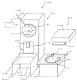
以下、図面を参照して本発明の実施の形態について説明する。ここで図1乃至図40は本発明によるキャリアテープ巻取収納装置及びキャリアテープ巻取収納方法を示す図である。
DESCRIPTION OF THE PREFERRED EMBODIMENTS Embodiments of the present invention will be described below with reference to the drawings. Here, FIG. 1 to FIG. 40 are views showing a carrier tape winding and storing apparatus and a carrier tape winding and storing method according to the present invention.
本発明によるキャリアテープ巻取収納装置は、電子部品等のワークWを保持して収納した長尺状のキャリアテープT0(図4参照)を円板状の空リールR0に巻取り、巻取ったリールR1に対してラベルL0を貼付してラベル付リールR2を作製し、このラベル付リールR2をストッカ102に落下させて収納するものである。
The carrier tape take-up and storage device according to the present invention winds and takes up a long carrier tape T0 (see FIG. 4) holding and storing a work W such as an electronic component on a disk-shaped empty reel R0. A label L0 is affixed to the reel R1 to produce a labeled reel R2, and the labeled reel R2 is dropped into the
このようなキャリアテープ巻取収納装置は、図1に示すように、キャリアテープT0を垂直に保持した空リールR0に巻取る巻取部101と、巻取部101に隣接して設けられ空リールR0にキャリアテープT0を巻取って作製されたリールR1に対してラベルL0を貼付してラベル付リールR2を作製する貼付部104と、巻取部101からのリールR1を垂直方向に保持する第1の保持位置αと、第1の保持位置αに対して90°回転しリールR1を水平方向に保持する第2の保持位置βをとる保持板105と、第2の保持位置βをとる保持板105の下方に設けられラベル付リールR2を収納するストッカ102とを備えている。
As shown in FIG. 1, such a carrier tape take-up and storage device includes a take-up
このうち巻取部101は内部に回転自在のモータを設置した回転駆動部101aを有し、モータの回転軸101bは回転駆動部101aの前面に突出し、モータの回転により矢印Aの方向に回転する。
Of these, the winding
回転駆動部101aの前面側には、上述のようにキャリアテープT0を巻き取ったリールR1を保持する保持手段としての保持板105が配置されている。保持板105は長方形の薄板で、その一辺には位置決めブロック106が固着されている。位置決めブロック106は直方体形状を有し、中央部に保持板105の板面側であって板面に対して直交して円弧状の位置決め凹部106aが形成されている。この位置決め凹部106aは、リールの半径と略同一の曲率半径を有している。
A holding
保持板105は図示されない駆動機構の作用により、垂直となる第1の保持位置αと水平となる第2の保持位置βとの間で、矢印J及び矢印Kのように略90°回転する。
The holding
図1において、保持板105が第1の保持位置αにある場合を実線で示し、第2の保持位置βにある場合を破線で示している。
In FIG. 1, the case where the holding
保持板105が第1の保持位置αにある場合は、キャリアテープT0を巻き取ったリールR1は回転駆動部101aの前面と保持板105との間に垂直に保持される。このとき、位置決め凹部106aは上側に向けて開口する。また、保持板105が第2の保持位置βにある場合は、キャリアテープを巻き取ったリールR1は保持板105の上面に水平に載置される。保持板105の一面(第2の保持位置βをとる保持板105の下面)には、貼付部104に近い一辺のやや内側に凸部としての2個の突起105a1、105a2が形成されている。
When the holding
突起105a1、105a2は、保持板105が第1の保持位置αにある場合には回転駆動部101aの反対側にあり、保持板105が第2の保持位置βにある場合には下側にくる。
The protrusions 105a1 and 105a2 are on the opposite side of the rotation driving unit 101a when the holding
貼付部104は巻取部101に隣接して設けられ、キャリアテープT0を巻き取ったリールR1にキャリアテープに収納されているワークの品名、定格、製造ロット番号等を記載したラベルを貼付する貼付手段として機能する。貼付部104は内部に回転自在のモータを設置した基台104aを有し、基台104aの上面には、垂直方向に上向きのスピンドル104bを有するターンテーブル104cが設置されている。このターンテーブル104cは基台104a内部のモータにより矢印Uの方向に回転するとともに、図示されない駆動機構により、矢印F及び矢印Gの方向に上下移動自在となっている。
The affixing
また、基台104aの上方において、後方となる位置にプリンタ104dが設置されている。プリンタ104dはリールR1に貼付するラベルを印刷する機能を有し、プリンタ104dの前面には印刷されたラベルを載置するためのラベル置き台104eが設置されている。 In addition, a printer 104d is installed at a position behind the base 104a. The printer 104d has a function of printing a label to be attached to the reel R1, and a label placing table 104e for placing the printed label is installed on the front surface of the printer 104d.
巻取部101の回転駆動部101aの前面と、貼付部104の基台104aの上面との間に、図示しない駆動機構によって矢印D及び矢印Eの方向に往復する搬送手段としての搬送トレイ103が設置されている。搬送トレイ103は長方形の平板形状をなす搬送板103Aと、搬送板103Aのうち貼付部104と反対側の端部に設けられた枠体103bとを有し、搬送板103Aにはターンテーブル104cの直径よりもやや大きい直径を有する通過穴103aが開口している。
Between the front surface of the rotation drive unit 101a of the winding
搬送トレイ103の回転駆動部101aの前面における停止位置は、ストッカ102の直上であり、かつ第2の保持位置βにある保持板105と対向する位置すなわち保持板105の直下である。また、搬送トレイ103の基台104aの上面における停止位置は、通過穴103aがターンテーブル104cの直上となる位置である。
The stop position of the
図1においては、搬送トレイ103が回転駆動部101aの前面における停止位置に停止している様子を示している。搬送トレイ103は、その上面に巻取部101においてキャリアテープを巻き取ったリールR1を水平に載置して、巻取部101から貼付部104に向けて搬送し、貼付部104において水平に保持されてラベルを貼付したリール(ラベル付リール)R2を水平に載置して、貼付部104から巻取部101に向けて搬送する。搬送板103Aの貼付部104から遠い側の端部となる一辺には、枠体103bが設けられている。
FIG. 1 shows a state where the
枠体103bは搬送板103Aに近い下側に空隙103dを有し、枠体103bと搬送板103Aとにより側面からみてL字形状を形成している。また枠体103bのうち空隙103dの上側の部分には、押出手段としての押出板103c1及び103c2が設置されている。押出板103c1及び103c2は枠体103bから貼付部104側に向けて互いに反対の斜め方向に突出した2枚の平板からなる。キャリアテープを巻き取ったリールR1が第2の保持位置βにある保持板105の上面に水平に載置され、ラベルを貼付したリールR2が保持板105の直下位置に停止している搬送トレイ103の上面に水平に載置されている様子を、図1におけるX方向矢視図として図2に示す。また、同じ様子を図1におけるY方向矢視図として図3に示す。
The
図2に示すように、保持板105はキャリアテープを巻き取ったリールR1を上面に水平に載置し、押出板103c1,103c2は保持板105の上面側かつリールR1と略同一高さに位置している。また、保持板105の下面に設けられた突起105a1,105a2は、搬送トレイ103の上面に水平に載置されたリールR2に対して、搬送トレイ103が貼付部104に向けて移動する矢印Dの方向、すなわち貼付部104に近い側に位置しており、その下端はリールR2の上面よりも低い位置にある。
As shown in FIG. 2, the holding
また、図3に示すように、搬送トレイ103の上面に水平に載置されたリールR2と保持板105は、枠体103bの搬送板103Aに近い下側に設けられた空隙103dの上端よりも下側に位置している。
Further, as shown in FIG. 3, the reel R2 and the holding
また、図1に示すように、搬送トレイ103の回転駆動部101aの前面における停止位置の直下位置には、貼付部104においてラベルを貼付したリールR2を収納するストッカ102が配置されている。ストッカ102は、図示されない駆動機構により矢印B及び矢印Cの方向に移動自在の載置テーブル102aを有する。
As shown in FIG. 1, a
ストッカ102の載置テーブル102aは3方向をストッカ枠102b1、102b2、102b3により囲まれており、載置テーブル102aの装置前面側は解放されている。また、載置テーブル102aは装置前面側がストッカ枠102b2側よりもやや高くなるように傾斜している。
The loading table 102a of the
このようなキャリアテープ巻取装置100を構成する各部の動作を制御するために、制御部100aが設けられている。なお、本発明の説明に関連する図面を見やすくするために、図中の保持板105は透明体として描かれているが、実際の装置においては保持板105を特に透明体により形成する必要はない。
In order to control the operation of each part constituting such a carrier
次に以上のような構成を有するキャリアテープ巻取収納装置100の作用、すなわちキャリアテープ巻取収納方法について、図4乃至図34を用いて以下詳述する。
Next, the operation of the carrier tape take-up and
なお、以下の説明において、特に強調する必要がない場合は、「キャリアテープを巻き取ったリールR1」を単に「リールR1」と記載し、同様に、「ラベルを貼付したリールR2」を単に「リールR2」と記載する。 In the following description, unless particularly emphasized, “reel R1 around which the carrier tape is wound” is simply referred to as “reel R1”, and similarly, “reel R2 with a label attached” is simply referred to as “reel R1”. Reel R2 ".
図4に示すように、空のリールR0がキャリアテープ巻取装置100に供給され、制御部100aの作用により、図示されない搬送機構がリールR0を搬送する。そして、搬送機構は、キャリアテープT0をリールR0に巻き取る巻取手段としての巻取部101を構成する回転駆動部101a内に設置されたモータの回転軸101bと、リールR0の略中心部に設けられた断面が円形状の中心穴Rcを嵌合させるように、リールR0を位置決めする。
As shown in FIG. 4, an empty reel R0 is supplied to the carrier
次に、図示されない装着機構の作用により、リールR0の中心穴Rcが回転軸101bに固定装着される。そして、図示されない接続機構が電子部品等のワークWを収納した長尺のキャリアテープT0の先端部をリールR0の図示されない溝部に挿入して、キャリアテープT0がリールR0に接続される。次に、制御部100aの作用により、回転駆動部101a内に設置されたモータが回転を開始する。これによって、回転軸101bが矢印Aの方向に回転して、リールR0が垂直に保持された状態でキャリアテープT0がリールR0に巻き取られる。 Next, the center hole Rc of the reel R0 is fixedly mounted on the rotating shaft 101b by the action of a mounting mechanism (not shown). Then, a connection mechanism (not shown) inserts the leading end of the long carrier tape T0 containing the workpiece W such as an electronic component into a groove (not shown) of the reel R0, and the carrier tape T0 is connected to the reel R0. Next, the motor installed in the rotation drive unit 101a starts to rotate by the action of the control unit 100a. As a result, the rotation shaft 101b rotates in the direction of arrow A, and the carrier tape T0 is wound around the reel R0 while the reel R0 is held vertically.
このとき保持板105は第1の保持位置αに位置しており、搬送トレイ103はストッカ102の直上位置に停止している。搬送トレイ103及び載置テーブル102aの上には何も載置されておらず、載置テーブル102aはストッカ枠102b1、102b2、102b3により囲まれた空間内で最も高い位置すなわち搬送トレイ103に最も近い位置にある。これが載置テーブル102aの初期位置である。
At this time, the holding
図5にキャリアテープT0の巻き取りが完了した直後の様子を示す。巻き取りが完了したことを制御部100aが検知すると、図示されない切断機構の作用により余分なキャリアテープT0が切り取られる。そして、キャリアテープT0を巻き取ったリールR1は、図示されない搬送機構の作用により回転軸101bから取り外されて矢印M1の方向に搬送され、回転駆動部101aの前面と第1の保持位置αにある保持板105との間の空間に垂直に保持される。
FIG. 5 shows a state immediately after the winding of the carrier tape T0 is completed. When the control unit 100a detects that the winding is completed, the excess carrier tape T0 is cut off by the action of a cutting mechanism (not shown). Then, the reel R1 around which the carrier tape T0 has been wound is removed from the rotating shaft 101b by the action of a transport mechanism (not shown) and transported in the direction of the arrow M1, and is in the first holding position α with the front surface of the rotation driving unit 101a. It is held perpendicular to the space between the holding
このとき、保持板105の下端に固着された位置決めブロック106に形成された位置決め凹部106aは上側に向けて開口しており、かつこの位置決め凹部106aの曲率半径がリールR1の半径と略同一であるため、リールR1の下端部と位置決め凹部106aとが安定して接触し、リールR1の位置決めが行われる。第1の保持位置αにおいてリールR1の位置決めが行われたことを制御部100aが検知すると、図示されない搬送機構が再び空のリールR0を巻取部101に向けて搬送し、図示されない装着機構が回転軸101bにリールR0を固定装着する。これをリール交換と呼ぶ。
At this time, the
次に図6のように、図示されない駆動機構の作用により、保持板105が第1の保持位置αから矢印Jの方向に略90°回転し、第2の保持位置βに移動する。これに伴ってリールR1も略90°回転して水平位置をとり、第2の保持位置βにおいて水平に保持された保持板105の上面に載置される。
Next, as shown in FIG. 6, the holding
ここで、リールR1にラベルを貼付する位置はあらかじめ決められており、図6においては、その位置を破線で囲んでラベル貼付領域Laとして示している。ただし、実際のリールR1には破線は記載されておらず、ラベル貼付領域Laの位置は貼付部104に設置された図示されないセンサによって検知されている。
Here, the position where the label is applied to the reel R1 is determined in advance, and in FIG. 6, the position is surrounded by a broken line and indicated as a label application area La. However, a broken line is not described in the actual reel R1, and the position of the label pasting area La is detected by a sensor (not shown) installed in the
第2の保持位置βにおいて保持板105の上面にリールR1が載置されたことを制御部100aが検知すると、図7(a)(b)に示すように、図示されない駆動機構の作用により搬送トレイ103が貼付部104に向けて矢印Dの方向に移動を開始する。そして、図8に示すように、搬送トレイ103の矢印D方向への移動に伴い、枠体103bに設置された押出板103c1及び103c2が矢印D方向へ移動して、保持板105の上面に載置されたリールR1の外周に当接する。
When the control unit 100a detects that the reel R1 is placed on the upper surface of the holding
この間、図2及び図3に示すように、保持板105は枠体103bに設けられた空隙103dの上端よりも下側に位置しているので、搬送トレイ103が矢印Dの方向に移動すると、図7乃至図9に示すように、保持板105は空隙103dを通過することができる。そして、図9に示すように、リールR1は押出板103c1及び103c2によって矢印Dの方向に押され、保持板105の上面から矢印M2の方向に落下して、搬送トレイ103の上面に移載される。
During this time, as shown in FIGS. 2 and 3, since the holding
図6乃至図9における保持板105上のリールR1の移動の様子を、図1におけるZ方向から見た矢視図(平面図)として、図10乃至図14に示す。図10は、図6においてリールR1が保持板105の上面に載置された様子を示す。リールR1の端部は位置決め凹部106aと接触した状態にある。
The movement of the reel R1 on the holding
ここから搬送トレイ103が、図11に示すように矢印Dの方向に移動を開始する。ここで、図2及び図3に示すように、押出板103c1及び103c2は保持板105の上面側かつリールR1と略同一高さに位置している。このため、移動開始後しばらくすると、図12に示すように、押出板103c1がリールR1の外周に点γ1において当接する。
From here, the
この状態からさらに搬送トレイ103が矢印Dの方向に移動すると、点γ1における当接に起因する力によって、リールR1は位置決め凹部106aから離間して、図13に示すように、押出板103c1及び103c2にそれぞれ点γ1及び点γ2で当接しながら、矢印Dの方向に移動するようになる。そして、図14に示すように、リールR1は保持板105の上面から押し出されて、その後図9中の矢印M2のように搬送トレイ103の上面に移載される。
When the
以上の説明に従って、リールR1が保持板105の上面から押し出されて、搬送トレイ103の上面に移載されるまでの様子を、図6乃至図9においては、図1におけるX方向矢視図として、図6(b)乃至図9(b)で表記している。この保持板105から搬送トレイ103への移載時に、搬送板103Aにおいて通過穴103aをリールR1が保持板105から移載される位置近傍に開口することにより、搬送トレイ103の進行方向についてのリールR1の位置決めが行われ、同時に、上述のように保持板105の上面に載置されたリールR1の外周が押出板103c1,103c2に2点で当接して押し出されることにより、搬送トレイ103の進行方向と直交する方向についてのリールR1の位置決めが行われる。これらの位置決めにより、保持板105から搬送トレイ103に移載されたリールR1は、搬送板103Aに開口する通過穴103aの上に載置される。
In accordance with the above description, the state from when the reel R1 is pushed out from the upper surface of the holding
そして、搬送トレイ103は、図15に示すように更に矢印Dの方向に移動し、図16のように、貼付部104を構成する基台104aの上側において、上述のように搬送板103Aに開口する通過穴103a(図1)が基台104a上に設置されたターンテーブル104c(図1)の直上となる位置で停止する。そして、図示されない位置決め機構の作用により、リールR1の中心穴Rcがターンテーブル104cのスピンドル104bの直上となるように位置決めされる。
Then, the
なお、図16において、全体の斜視図を図16(a)として表記し、位置決めされた搬送トレイ103、リールR1の中心穴Rc、およびターンテーブル104cを図16(a)の矢印Vの方向から見た矢視断面図を図16(b)に示す。
In FIG. 16, the overall perspective view is shown as FIG. 16A, and the positioned
この時点で巻取部101におけるリール交換が完了し、回転軸101bと新しい空リールR0の中心穴Rcの位置決め及び固定装着が行われ、キャリアテープT0とリールR0とが接続された状態となる。そして、回転駆動部101a内に設置されたモータが回転を開始して回転軸101bが矢印Aの方向に回転し、キャリアテープT0の空のリールR0への巻き取りが開始される。
At this time, the reel replacement in the winding
次に、上述のようにリールR1の中心穴Rcとターンテーブル104cのスピンドル104bの位置決めが行われたことを制御部100aが検知すると、図17に示すように、図示されない駆動機構の作用によりターンテーブル104cが矢印Fの方向に上昇して、直上に位置する搬送板103Aの通過穴103a(図1)を貫通する。そして、リールR1の中心穴Rcがスピンドル104bに嵌合して固定装着される。
Next, when the control unit 100a detects that the center hole Rc of the reel R1 and the spindle 104b of the turntable 104c have been positioned as described above, as shown in FIG. The table 104c rises in the direction of the arrow F and passes through the
次に、リールR1に設けられたラベル貼付領域Laの位置が図示されないセンサにより検出され、その検出情報が制御部100aに送付される。そして、この検出情報に基づいて、制御部100aが図示されない駆動機構を駆動させ、図18に示すように、ラベル貼付領域Laがプリンタ104dの直前位置となるように矢印Uの方向にターンテーブル104cが回転して停止する。 Next, the position of the label sticking area La provided on the reel R1 is detected by a sensor (not shown), and the detection information is sent to the control unit 100a. Then, based on this detection information, the control unit 100a drives a drive mechanism (not shown), and as shown in FIG. 18, the turntable 104c in the direction of the arrow U so that the label attaching region La is located immediately before the printer 104d. Stops rotating.
次に、ラベル貼付領域Laがプリンタ104dの直前位置となったことを制御部100aが検知すると、図示されない駆動機構の作用により、図19に示すように、ターンテーブル104cが矢印Gの方向に下降し、リールR1の中心穴Rcがスピンドル104bから外れる。そして、その間にプリンタ104dがラベルL0を印刷してラベル置き台104e上に載置する。このとき、ラベルL0の下面には貼付用の糊が付着しているが、ラベル置き台104eの上面は、糊によりラベルL0が付着するのを防止するように、表面処理が施されている。 Next, when the control unit 100a detects that the label attaching area La is located immediately before the printer 104d, the turntable 104c is lowered in the direction of the arrow G as shown in FIG. Then, the center hole Rc of the reel R1 is disengaged from the spindle 104b. In the meantime, the printer 104d prints the label L0 and places it on the label table 104e. At this time, adhesive paste is attached to the lower surface of the label L0, but the upper surface of the label placing table 104e is subjected to surface treatment so as to prevent the label L0 from attaching due to the adhesive.
この間に、図示されない駆動機構の作用により、保持板105は第2の保持位置βから矢印Kの方向に略90°回転して、第1の保持位置αに戻る。なお、図17乃至図19においては、装置の斜視図を図17(a)乃至図19(a)として表記し、図17(a)乃至図19(a)におけるV方向矢視図を図17(b)乃至図19(b)として表記している。
During this time, the holding
次に、図20に示すように、制御部100aの作用により、ラベル置き台104eに載置されたラベルL0は図示されない吸着ノズルに吸着された状態で、矢印NのようにリールR1のラベル貼付領域Laに向けて搬送され、吸着ノズルはラベルL0を吸着したままラベル貼付領域LaにラベルL0を上方から押圧して貼付する。その後、吸着ノズルは吸着を解除してラベル貼付領域Laから離間する。 Next, as shown in FIG. 20, the label L0 placed on the label mounting table 104e is attracted to a suction nozzle (not shown) by the action of the control unit 100a, and the label R1 is attached to the reel R1 as indicated by an arrow N. It is conveyed toward the area La, and the suction nozzle presses and sticks the label L0 to the label application area La from above while adsorbing the label L0. Thereafter, the suction nozzle releases suction and moves away from the label pasting area La.
このようにして、貼付部104は搬送トレイ103にリールR1を水平に載置した状態でラベルL0を貼付する。
In this way, the affixing
ラベルL0がリールR1に貼付されたことを制御部100aが検知すると、ラベルL0を貼付したリールR2を載置した搬送トレイ103は、図21に示すように、巻取部101に向けて矢印Eの方向に移動を開始する。そして、図22に示すように、図4と同様のストッカ102の直上位置で停止する。
When the control unit 100a detects that the label L0 has been attached to the reel R1, the
次に、巻取部101におけるキャリアテープT0の巻き取りが完了し、これを制御部100aが検知する。この様子を図23に示す。
Next, the winding of the carrier tape T0 in the winding
キャリアテープT0を巻き取ったリールR1は、図5に示す場合と同様に、図示されない切断機構の作用により余分なキャリアテープT0が切り取られ、図示されない搬送機構の作用により回転軸101aから取り外されて矢印M1の方向に搬送され、回転駆動部101aの前面と第1の保持位置αにある保持板105との間に垂直に保持される。次に、図24に示すように、図示されない駆動機構の作用により、保持板105が第1の保持位置αから矢印Jの方向に略90°回転し、第2の保持位置βに移動する。これに伴ってリールR1も略90°回転して水平となり、第2の保持位置βにおいて水平に保持された保持板105の上面に載置される。この動作は図6に示す場合と略同様であるが、図24において、リールR1が第2の保持位置βにおいて水平に保持された保持板105の上面に載置されたとき、保持板105の下面と対向する搬送トレイ103の上面には、ラベルLを貼付したリールR2が載置されている。この点は図6に示す場合とは異なっている。
As with the case shown in FIG. 5, the reel R1 around which the carrier tape T0 is wound is cut off from the rotating shaft 101a by the action of a transport mechanism (not shown). It is conveyed in the direction of the arrow M1 and is held vertically between the front surface of the rotation drive unit 101a and the holding
次に、図25に示すように、搬送トレイ103が貼付部104に向けて矢印Dの方向に移動を開始する。
Next, as shown in FIG. 25, the
この点は図7に示す場合と略同様であり、図25乃至図28における保持板105の上面に載置されたリールR1と押出板103c1及び103c2の動作は、図7乃至図9と略同様である。
This is substantially the same as the case shown in FIG. 7, and the operations of the reel R1 and the extrusion plates 103c1 and 103c2 placed on the upper surface of the holding
この間、図25において搬送トレイ103の上面に載置されているラベルL0を貼付したリールR2は、図26において保持板105の下面に設けられた突起105a1、105a2と当接し、搬送トレイ103とともに矢印Dの方向に移動することを阻止される。そして、図2及び図3に示すように、リールR2は枠体103bの搬送板103Aに近い下側に設けられた空隙103dの上端よりも下側に位置しているので、搬送トレイ103が矢印Dの方向に移動すると、搬送トレイ103とともに矢印Dの方向に移動することを阻止された状態のままで、図26乃至図27に示すように空隙103dを通過することができる。
During this time, the reel R2 to which the label L0 placed on the upper surface of the
その後、リールR2は、図27における矢印M3の方向に落下して、図28に示すように、ストッカ102の載置テーブル102a上に収納される。リールR2が載置テーブル102a上に収納されたことを制御部100aが検知すると、図示されない駆動機構の作用により、載置テーブル102aは図1における矢印Bの方向に下降する。その後も載置テーブル102aは、リールR2が1個載置される都度、図示されない駆動機構の作用により矢印Bの方向に下降する。
Thereafter, the reel R2 drops in the direction of the arrow M3 in FIG. 27 and is stored on the mounting table 102a of the
載置テーブル102aがそれ以上下降できなくなる位置まで下降すると、載置テーブル102a上にリールR2が満杯になったことを意味する。ストッカ102にはその位置を検知する図示されないセンサが設置されており、その検知情報が音と表示で外部に通知され、キャリアテープ巻取装置100は動作を停止する。
When the mounting table 102a is lowered to a position where it cannot be lowered any more, it means that the reel R2 is full on the mounting table 102a. The
この通知により、装置の担当者はストッカ102内のリールR2をすべて搬出する。リールR2がすべて搬出されたことを上記センサが検知すると、載置テーブル102aは図示されない駆動機構の作用により図1に示す矢印Cの方向に上昇して初期位置に戻る。リールR2が満杯となる数量は20個から30個程度に設定されることが多い。
By this notification, the person in charge of the apparatus carries out all the reels R2 in the
一方、図24において保持板105の上面に載置されたリールR1は、搬送トレイ103が図25に示す矢印Dの方向に移動を開始すると、図26乃至図28に示すように、押出板103c1,103c2の作用により矢印Dの方向に押され、保持板105の上面から図28に示す矢印M4の方向に落下して、直前にリールR2が載置テーブル102aに落下して空になった搬送トレイ103の上面に移載される。このときの押出板103c1,103c2の作用については、図6乃至図9を用いて説明したので、ここでは説明を省略する。
On the other hand, when the
以上のように、保持板105の上面から搬送トレイ103の上面にリールR1が移載されると、搬送トレイ103は図28に示す矢印Dの方向にさらに移動し、図34に示すように、貼付部104を構成する基台104aの上側において、搬送板103Aに開口する通過穴103a(図1)が基台104a上に設置されたターンテーブル104c(図1)の直上となる位置で停止する。その後、貼付部104の作用により、図17乃至図20と同様にリールR1にラベル貼付が行われる。
As described above, when the reel R1 is transferred from the upper surface of the holding
次に搬送トレイ103上のリールR2の挙動を以下詳述する。ここで図24乃至図28における搬送トレイ103上のリールR2の移動の様子を、図1におけるZ方向矢視図(平面図)として、図29乃至図33に示す。ただし、図を見やすくするために、図29乃至図33においては保持板105の上面に載置されたリールR1を省略し、透視図として表記している。
Next, the behavior of the reel R2 on the
図29は、図24においてリールR2が搬送トレイ103の上面に載置された様子を示す。まず搬送トレイ103が、図25に示すように矢印Dの方向に移動を開始する。ここで、図2に示すように、保持板105の下面に設けられた突起105a1及び105a2は、搬送トレイ103の上面に水平に載置されたリールR2に対して、搬送トレイ103が貼付部104に向けて移動する矢印Dの方向、すなわち貼付部104に近い側に位置しており、その下端はリールR2の上面よりも低い位置にある。このため、搬送トレイ103の移動開始後しばらくすると、図30に示すように、突起105a1がリールR2の外周に点δ1において当接する。
FIG. 29 shows a state where the reel R2 is placed on the upper surface of the
この状態からさらに搬送トレイ103が移動すると、点δ1における当接に起因する力によって、リールR2は図31及び図32に示すように、突起105a1、105a2にそれぞれ点δ1及び点δ2で当接しながら、矢印Dの方向に移動することを阻止される。そして、図33に示すように、リールR2は搬送トレイ103の上面から押し出されて、その後図27における矢印M3のようにストッカ102の載置テーブル102a上に落下する。
When the
以上のように、リールR2が搬送トレイ103の上面から押し出されて、載置テーブル102aの上に落下し、その後、リールR1が保持板105の上面から押し出されて、搬送トレイ103の上面に移載される。この間の様子を、図24乃至図28においては、図1におけるX方向矢視図として、図24(b)乃至図28(b)で表記している。ただし、簡単のため、載置テーブル102aを始めとするストッカ102は表記していない。
As described above, the reel R2 is pushed out from the upper surface of the
以上のようなキャリアテープ巻取装置100の動作を、各部の名称を横軸に、時刻を縦軸にとった状態遷移図として図35に示す。図35において、時刻t1からt10の意味は以下のとおりである。t1はキャリアテープの巻き取り完了である。また、t2はキャリアテープを巻き取ったリールR1の回転軸からの取り外し開始である。また、t3は水平なリールR1の搬送手段への移載開始である。また、t4はリールR1の巻取部から貼付部への搬送開始である。また、t5はリールR1の貼付部への搬送完了である。また、t6はラベル貼付開始である。また、t7はラベル貼付完了である。また、t8はリールR2の貼付部から巻取部への搬送開始である。また、t9はリールR2の巻取部への搬送完了である。また、t10はリールR2のストッカへの収納である。時間は上から下に向けて経過している。すなわち、時刻t1、t2の順に時間が経過し、時刻t10は後述のように時刻t5及び時刻t6と同一になり、時刻t9の後の時刻t1で1周期となる。また、図35において、枠内には各部の状態或いは動作を記載し、対応する図がある場合には、当該の図番を記載している。また、リールR1、R2の移動経路を、矢印φ1乃至矢印φ7により示している。
The operation of the carrier
図35と後述する比較例の状態遷移図としての図91を比較すると、図91においては時刻t1から時刻t10までがこの順に直列に経過しているのに対して、図35においては時刻t3と時刻t4、時刻t5と時刻t6と時刻t10、時刻t7と時刻t8がそれぞれ同一時点において経過している。これは、例えば時刻t3と時刻t4、すなわち水平なリールR1の搬送手段への移載開始とリールR1の巻取部から貼付部への搬送開始が略同時に実行されていることを示す。 When FIG. 35 is compared with FIG. 91 as a state transition diagram of a comparative example which will be described later, in FIG. 91, time t1 to time t10 elapse in series in this order, whereas in FIG. Time t4, time t5, time t6 and time t10, and time t7 and time t8 have elapsed at the same time point. This indicates that, for example, time t3 and time t4, that is, the start of transfer of the horizontal reel R1 to the transport means and the start of transport of the reel R1 from the winding unit to the pasting unit are executed substantially simultaneously.
具体的には、図25乃至図28において、搬送トレイ103が矢印Dの方向に移動することにより、第2の保持位置βに位置する保持板105上に載置されたリールR1が、搬送板103Aの枠体103bに設けられた押出板103c1および103c2により押し出されて搬送トレイ103上に移載されることに対応している。
Specifically, in FIGS. 25 to 28, when the
同様に、時刻t5と時刻t6については、図16乃至図20において、貼付部104はリールR1を搬送トレイ103上に載置した状態でラベル貼付を行っているため、リールR1の貼付部104への搬送完了時点である時刻t5とラベル貼付開始である時刻t6が同一時点となる。また、時刻t6と時刻t10については、図25乃至図28において、搬送トレイ103が矢印Dの方向に移動することにより、搬送トレイ103上に載置されたリールR2が保持板105の下面に設けられた突起105a1、105a2と当接し、搬送トレイ103とともに矢印Dの方向に移動することを阻止され、ストッカ102の載置テーブル102a上に収納されるため、ラベル貼付開始である時刻t6とリールR2のストッカ102への収納である時刻t10が同一時点となる。
Similarly, at time t5 and time t6, in FIG. 16 to FIG. 20, the
このように、複数の時刻が同一時点となることは、処理時間が短縮されることに他ならない。本発明における実際の処理時間の例をあげると、時刻t1から時刻t6まで、すなわちキャリアテープの巻き取り完了からラベル貼付開始までの時間は約12秒である。 As described above, the fact that a plurality of times are the same time is nothing other than a reduction in processing time. Taking an example of the actual processing time in the present invention, the time from the time t1 to the time t6, that is, the time from the completion of winding the carrier tape to the start of labeling is about 12 seconds.
比較例においては、この時間は後述のように約38秒である。また、本発明における時刻t7から時刻t9まで、すなわちラベル貼付完了からリールR2の巻取部への搬送完了までの時間は約2秒である。比較例においては、この時間は後述のように約19秒である。また、比較例における時刻t9から時刻t10まで、すなわちリールR2の巻取部への搬送完了からリールのストッカへの収納までの時間は後述のように約8秒である。ところが、本発明におけるリールのストッカへの収納は、時刻t4から時刻t5まで、すなわちリールR1の巻取部から貼付部への搬送開始からリールR1の貼付部への搬送完了までの間に行われる。 In the comparative example, this time is about 38 seconds as described later. Further, the time from the time t7 to the time t9 in the present invention, that is, the time from the completion of label sticking to the completion of conveyance of the reel R2 to the winding unit is about 2 seconds. In the comparative example, this time is about 19 seconds as described later. Further, in the comparative example, the time from the time t9 to the time t10, that is, the time from the completion of the conveyance of the reel R2 to the winding unit to the storage of the reel in the stocker is about 8 seconds as described later. However, the storage of the reels in the stocker according to the present invention is performed from time t4 to time t5, that is, from the start of conveyance of the reel R1 from the winding unit to the affixing unit until the completion of conveyance of the reel R1 to the affixing unit. .
このため比較例における時刻t9から時刻t10まで、すなわちリールR2の巻取部への搬送完了からリールのストッカへの収納までの時間に相当する時間は、本発明においては時刻t4から時刻t5まで、すなわちリールR1の巻取部から貼付部への搬送開始からリールR1の貼付部への搬送完了までの時間に含まれてしまうため、この時間は処理時間に加算されない。また、時刻t6から時刻t7まで、すなわちラベル貼付開始から完了までの時間は比較例と同一の約27秒である。その理由は、貼付部の機能が後述する比較例と同一であるためである。 For this reason, the time corresponding to the time from the time t9 to the time t10 in the comparative example, that is, the time from the completion of the conveyance of the reel R2 to the winding unit until the reel is stored in the stocker, is from the time t4 to the time t5 in the present invention. That is, since it is included in the time from the start of conveyance of the reel R1 from the winding unit to the affixing unit to the completion of conveyance of the reel R1 to the affixing unit, this time is not added to the processing time. Further, the time from the time t6 to the time t7, that is, the time from the start of label sticking to the completion is about 27 seconds, which is the same as the comparative example. The reason is that the function of the sticking part is the same as that of the comparative example described later.
以上により、本発明によるキャリアテープ巻取収納装置100の処理時間の1周期は、時刻t9から時刻t10までの5秒は加算されず、12+27+2=約41秒である。この値は後述する比較例の場合の約84秒に比べて、約50%の短縮となっている。
As described above, one cycle of the processing time of the carrier tape take-up and
このように、本発明によってキャリアテープ巻取収納装置の動作の1周期の処理時間が大きく短縮される理由は、以下のとおりと考えられる。 Thus, the reason why the processing time of one cycle of the operation of the carrier tape take-up and storage device is greatly shortened by the present invention is considered as follows.
本発明は、比較例が後述のように、進退自在の固定爪を内蔵する固定ユニットを取り付けた上下移動自在の搬送アームを用いてリールR1、R2を固定するのに対して、保持板或いは搬送トレイの上にリールR1、R2を載置した状態で、搬送トレイが水平方向に移動する際に、保持板に設けた突起の作用によりリールR2を搬送トレイからストッカに収納し、併せて搬送トレイに設けた押出板の作用により、リールR1を保持板から搬送トレイに移載している。このように、比較例においては後述のように、固定爪の進退や搬送アームの上下移動等のように時間を要する動作によってリールの収納、移載等の取り扱いを個別に実行しているのに対して、本発明においては搬送トレイの水平方向の移動時にその移動方向に働く力を利用して、リールの収納、移載等の取り扱いを同時に実行しているため、処理時間が大幅に短縮される。 In the present invention, as described later, the reels R1 and R2 are fixed by using a vertically movable carriage arm to which a fixed unit with a built-in movable claw is attached as described later. When the transport tray moves in the horizontal direction with the reels R1 and R2 placed on the tray, the reel R2 is stored in the stocker from the transport tray by the action of the protrusion provided on the holding plate, and the transport tray is also combined. The reel R1 is transferred from the holding plate to the transport tray by the action of the extrusion plate provided on the plate. Thus, in the comparative example, as will be described later, the handling and handling of reels are individually performed by time-consuming operations such as advancement / retraction of the fixed claw and vertical movement of the transfer arm. On the other hand, in the present invention, when the transport tray is moved in the horizontal direction, handling such as reel storage and transfer is simultaneously performed by using the force acting in the moving direction, so that the processing time is greatly shortened. The
また、本発明においては、貼付部において搬送トレイにリールR1を載置した状態でラベルを貼付している。これは、後述の比較例のように、搬送アームから貼付台にリールR1を移載してから貼付部がラベル貼付を行うものではないので、ラベル貼付が完了するまで搬送トレイ(比較例における搬送アーム)が巻取部に退避し、ラベル貼付が完了してから貼付部に復帰する必要がない。さらに、本発明においては、上記のように押出板の作用により、リールR1を保持板から搬送トレイに移載するため、第2の保持位置において搬送トレイを保持板の下側に位置させることができる。 Moreover, in this invention, the label is stuck in the state which mounted reel R1 on the conveyance tray in the sticking part. This is because, unlike the comparative example described later, since the affixing unit does not apply the label after the reel R1 is transferred from the conveying arm to the affixing stand, the conveying tray (conveying in the comparative example) is completed until the labeling is completed. It is not necessary to return to the affixing part after the arm) is retracted to the take-up part and the label affixing is completed. Furthermore, in the present invention, the reel R1 is transferred from the holding plate to the transport tray by the action of the extrusion plate as described above, so that the transport tray can be positioned below the holding plate at the second holding position. it can.
このため、後述の比較例のように、保持板が略90°回転を完了するまで搬送トレイ(比較例における搬送アーム)が貼付部に退避し、回転完了後に巻取部に復帰する必要がない。これらの退避と復帰を不要としたことで、全体の処理時間をさらに短縮することができる。また、上記のように、リールのストッカへの収納を、リールR1の巻取部から貼付部への搬送開始からリールR1の貼付部への搬送完了までの間に同時に行うため、その分、処理時間が短縮されている。 For this reason, unlike the comparative example described later, the transport tray (the transport arm in the comparative example) is retracted to the affixing portion until the holding plate completes the rotation of about 90 °, and it is not necessary to return to the winding portion after the rotation is completed. . By eliminating these saving and restoring operations, the entire processing time can be further shortened. Further, as described above, since the reels are stored in the stocker at the same time from the start of conveyance of the reel R1 from the winding unit to the affixing unit until the completion of conveyance of the reel R1 to the affixing unit, processing accordingly. Time has been shortened.
次に、本発明において、キャリアテープの巻き取りが完了するまでの時間が変化した場合について説明する。上述のように、空リールに巻き取られるキャリアテープの長さは一定ではなく、様々な長さである。このため、巻取部がキャリアテープの巻き取りに要する時間も様々である。図35におけるキャリアテープの巻き取りに要する時間は、時刻t3のやや後から時刻t1までのTaである。これに対して、キャリアテープの長さが短く、図35における時間Taよりも短い時間で巻き取りが完了した場合の状態遷移図を、図36に示す。図36におけるキャリアテープの巻き取りに要する時間は、時刻t3のやや後から時刻t1までのTbである。ここで、本発明においては、上記のように処理時間が短縮されており、図35および図36の時刻t9の時点で搬送トレイはリールR2を載置した状態で巻取部に停止している。この状態は、搬送トレイがキャリアテープの巻き取りが完了したリールR1を受け取ることが可能であることを意味する。図36において、時刻t9の直後の時刻t1にキャリアテープの巻き取りが完了しており、この場合には即座に保持板の回転によりリールR1を水平に保持し、搬送トレイを巻取部から貼付部に向けて移動させることにより、リールR1を搬送トレイに移載することができる。すなわち、上記のように、リールR1、R2の固定、搬送の所要時間を短縮したことによる処理時間の短縮により、比較例に比べてキャリアテープの巻き取り時間の変動に対する融通性が向上している。 Next, the case where the time until the winding of the carrier tape is completed in the present invention will be described. As described above, the length of the carrier tape wound around the empty reel is not constant and varies. For this reason, the time required for the winding unit to wind the carrier tape varies. The time required for winding the carrier tape in FIG. 35 is Ta from slightly after time t3 to time t1. In contrast, FIG. 36 shows a state transition diagram when the length of the carrier tape is short and the winding is completed in a time shorter than the time Ta in FIG. The time required for winding the carrier tape in FIG. 36 is Tb from slightly after time t3 to time t1. Here, in the present invention, the processing time is shortened as described above, and at time t9 in FIGS. 35 and 36, the transport tray stops at the winding unit with the reel R2 placed thereon. . This state means that the transport tray can receive the reel R1 for which the winding of the carrier tape has been completed. In FIG. 36, the winding of the carrier tape is completed at time t1 immediately after time t9. In this case, the reel R1 is immediately held horizontally by the rotation of the holding plate, and the transport tray is pasted from the winding unit. By moving toward the part, the reel R1 can be transferred to the transport tray. That is, as described above, the processing time is shortened by shortening the time required for fixing and transporting the reels R1 and R2, thereby improving the flexibility with respect to the variation in the winding time of the carrier tape as compared with the comparative example. .
次に本発明の変形例について述べる。 Next, modifications of the present invention will be described.
上記実施の形態においては、保持板105の下面に凸部として2個の突起105a1、105a2を設けた例を示したが、凸部の形状は2個の突起に限定されるものではない。凸部の他の例を図37及び図38に示す。
In the above embodiment, the example in which the two protrusions 105a1 and 105a2 are provided as the protrusions on the lower surface of the holding
図37は、図1において搬送板103Aの枠体103bに設けた押出板103c1及び103c2と同様の形状を有する2個の停止板105b1及び105b2を、保持板105の下面に設けた例を示す。また、図38は、図1において位置決めブロック106の中央部に設けた位置決め凹部106aと同様の形状を有する停止板105cを、保持板105の下面に設けた様子を示す。停止板105b1、105b2、105cはいずれも、保持板105の下側に位置する搬送トレイ103が図1に示す矢印Dの方向に移動する際に、搬送トレイ103に載置されたリールR2が矢印Dの方向に移動することを阻止して、リールR2をストッカ102に落下させて収納する作用を有している。
FIG. 37 shows an example in which two stop plates 105b1 and 105b2 having the same shape as the extrusion plates 103c1 and 103c2 provided on the
また、上記実施の形態においては、搬送板103Aの枠体103bに設ける押出手段として、枠体103bから貼付部104側に向けて互いに反対の斜め方向に突出した2枚の平板である押出板103c1及び103c2を設けた例を示したが、押出手段の形状は互いに反対の斜め方向に突出した2枚の平板に限定されるものではない。押出手段の他の例を図39及び図40に示す。
Further, in the above-described embodiment, as the extrusion means provided on the
図39は、図1において保持板105の一面に設けた2個の突起105a1、105a2と同様の形状を有する2個の押出突起103e1及び103e2を、枠体103bの貼付部104側に向けて設けた様子を示す。また、図40は、図1において位置決めブロック106の中央部に設けた位置決め凹部106aと同様の形状を有する押出板103fを、枠体103bの貼付部104側に向けて設けた様子を示す。押出突起103e1、103e2、押出板103fはいずれも、保持板105の下側に位置する搬送トレイ103が図1に示す矢印Dの方向に移動する際に、保持板105上に載置されたリールR1を矢印Dの方向に押し出して搬送トレイ103に移載する作用を有している。
39, two extrusion protrusions 103e1 and 103e2 having the same shape as the two protrusions 105a1 and 105a2 provided on one surface of the holding
また、図1において位置決めブロック106の中央部に設けた位置決め凹部106aについても、枠体103bに設けた互いに反対の斜め方向に突出した2枚の平板である押出板103c1及び103c2と同一形状の板を用いたり、保持板105の下面に設けた2個の突起105a1、105a2と同一形状の突起を用いることで、位置決め凹部106aと同様のリールR1の位置決めが可能である。
In addition, in FIG. 1, the
比較例
次に本発明をよりよく理解するため、キャリアテープ巻取収納装置の比較例について、図41乃至図92を用いて説明する。
Comparative Example Next, in order to better understand the present invention, a comparative example of the carrier tape take-up and storage device will be described with reference to FIGS.
図41乃至図43は、キャリアテープをリールに巻取り、この巻取済のリールをストッカに収納するキャリアテープ巻取収納装置の動作説明図である。 41 to 43 are operation explanatory views of the carrier tape take-up and storage device for winding the carrier tape on the reel and storing the wound reel in the stocker.
図41に示すように、空のリールR0がキャリアテープ巻取収納装置100Xに供給されると、制御部100Xaの作用により、図示されない搬送機構がリールR0を搬送する。そして、搬送機構は、キャリアテープT0をリールR0に巻き取る巻取手段としての巻取部101を構成する回転駆動部101a内に設置されたモータの回転軸101bと、リールR0の略中心部に設けられた断面が円形状の中心穴Rcを嵌合させるように、リールR0を位置決めする。
As shown in FIG. 41, when an empty reel R0 is supplied to the carrier tape take-up and storage device 100X, a transport mechanism (not shown) transports the reel R0 by the action of the controller 100Xa. Then, the transport mechanism has a rotation shaft 101b of a motor installed in a rotation drive unit 101a constituting a winding
次に、図示されない装着機構の作用により、リールR0の中心穴Rcが回転軸101bに固定装着される。そして、図42に示すように、制御部100Xaの作用により、図示されない接続機構が電子部品等のワークWを収納した長尺のキャリアテープT0の先端部をリールR0の図示されない溝部に挿入して、キャリアテープT0がリールR0に接続される。この状態で、リールR0の円板形状の面は垂直方向を向く。次に、制御部100Xaの作用により回転駆動部101a内に設置されたモータが回転を開始する。 Next, the center hole Rc of the reel R0 is fixedly mounted on the rotating shaft 101b by the action of a mounting mechanism (not shown). Then, as shown in FIG. 42, due to the action of the control unit 100Xa, the connection mechanism (not shown) inserts the leading end of the long carrier tape T0 containing the workpiece W such as an electronic component into the groove (not shown) of the reel R0. The carrier tape T0 is connected to the reel R0. In this state, the disk-shaped surface of the reel R0 faces the vertical direction. Next, the motor installed in the rotation drive unit 101a starts to rotate by the action of the control unit 100Xa.
これによって、回転軸101bが矢印Aの方向に回転してキャリアテープT0がリールR0に巻き取られる。巻き取りが完了したことを制御部100Xaが検知すると、図43に示すように、図示されない切断機構の作用により余分なキャリアテープT0が切り取られる。そして、キャリアテープT0を巻き取ったリールR1は、図示されない搬送機構の作用により回転軸101bから取り外されて、矢印Mの方向に搬送され、巻取部101の直下に位置するストッカ102に収納される。
As a result, the rotating shaft 101b rotates in the direction of arrow A, and the carrier tape T0 is wound around the reel R0. When the control unit 100Xa detects that the winding has been completed, as shown in FIG. 43, excess carrier tape T0 is cut off by the action of a cutting mechanism (not shown). Then, the reel R1 around which the carrier tape T0 has been wound is removed from the rotating shaft 101b by the action of a transport mechanism (not shown), transported in the direction of the arrow M, and stored in the
リールR1が回転軸101bから取り外されたことを制御部100Xaが検知すると、図示されない搬送機構が再び空のリールR0を巻取部101に向けて搬送し、図示されない装着機構が回転軸101bにリールR0を固定装着する。これをリール交換と呼ぶ。ストッカ102は、リールR1を載置テーブル102a上に重ねて載置する。載置テーブル102a上にリールR1が全く載置されないときの載置テーブル102aの位置が初期位置である。
When the controller 100Xa detects that the reel R1 has been removed from the rotary shaft 101b, a transport mechanism (not shown) transports the empty reel R0 toward the take-up
載置テーブル102aは、リールR1が1個載置される都度、図示されない駆動機構の作用により矢印Bの方向に下降する。載置テーブル102aがそれ以上下降できなくなる位置まで下降すると、載置テーブル102a上にリールR1が満杯になったことを意味する。 The placement table 102a is lowered in the direction of arrow B by the action of a drive mechanism (not shown) every time one reel R1 is placed. When the mounting table 102a is lowered to a position where it cannot be lowered any more, it means that the reel R1 is full on the mounting table 102a.
ストッカ102にはその位置を検知する図示されないセンサが設置されており、その検知情報が音と表示で外部に通知され、キャリアテープ巻取装置100Xは動作を停止する。この通知により、装置の担当者はストッカ102内のリールR1をすべて搬出する。リールR1がすべて搬出されたことを上記センサが検知すると、載置テーブル102aは図示されない駆動機構の作用により図41に示す矢印Cの方向に上昇して初期位置に戻る。リールR1が満杯となる数量は20個から30個程度に設定されることが多い。
The
なお、載置テーブル102aの装置正面側は、担当者がリールR1を搬出するために解放されている。このため、載置テーブル102a上のリールR1が装置正面側から滑落しないように、載置テーブル102aは装置正面側がやや高くなるように傾斜している。キャリアテープ巻取装置100Xの模式図を図50に示す。上記の説明のように、図50においてリールR1は矢印H1の方向すなわち上から下に搬送される。 In addition, the apparatus front side of the mounting table 102a is released for the person in charge to carry out the reel R1. For this reason, the mounting table 102a is inclined so that the front side of the apparatus is slightly higher so that the reel R1 on the mounting table 102a does not slide off from the front side of the apparatus. A schematic diagram of the carrier tape winding device 100X is shown in FIG. As described above, in FIG. 50, the reel R1 is conveyed in the direction of the arrow H1, that is, from the top to the bottom.
このようなキャリアテープ巻取収納装置100Xに対し、キャリアテープに収納されているワークの品名、定格、製造ロット番号等を記載したラベルをキャリアテープを巻き取ったリールに貼付する機能を付加したキャリアテープ巻取装置100Yについて説明する。
A carrier having a function of attaching a label describing the product name, rating, production lot number, etc. of a work housed in the carrier tape to a reel around which the carrier tape is wound, to the carrier tape take-up and storage device 100X. The
キャリアテープ巻取収納装置100Yはキャリアテープ巻取装置100Xに、図44乃至図49に示す貼付手段としての貼付部104Xを付加したものである。すなわち、巻取部101により空のリールR0にキャリアテープT0を巻き取った後、キャリアテープT0を巻き取ったリールR1を貼付部104Xまで搬送し、キャリアテープT0に収納されているワークの品名、定格、製造ロット番号等を記載したラベルをリールR1に貼付し、ラベルを貼付したリールR2をストッカ102に収納する。
The carrier tape take-up and
ラベルをリールR1に貼付する貼付部104Xの構成を図44(a)(b)により説明する。図44(a)は、貼付部104Xの全体を示す斜視図である。
The structure of the sticking
貼付部104Xの下方には基台104aが配置され、垂直方向に上向きのスピンドル104bを有するターンテーブル104cが設置されている。スピンドル104bの直径は、リールR1の中心穴Rcの内径よりもやや小さい。
A base 104a is disposed below the sticking
ターンテーブル104cは、基台104a内に設けられた図示されない駆動機構の作用により、矢印FおよびGの方向に昇降自在であり、かつスピンドル104bの周囲に矢印Uの方向に回転自在である。基台104aの上方には、図示されない支持機構により固定された貼付台104fが設置されている。貼付台104fにおいて、ターンテーブル104cの直上部分には、ターンテーブル104cの直径よりもやや大きい直径の通過穴104gが開口している。
The turntable 104c is movable up and down in the directions of arrows F and G by the action of a driving mechanism (not shown) provided in the base 104a, and is rotatable in the direction of arrow U around the spindle 104b. Affixing
貼付台104fおよびターンテーブル104cを、基台104aの正面である矢印V方向から見た矢視断面図を、図44(b)に示す。ターンテーブル104cは、スピンドル104bの最上部が貼付台104fの下面よりも低い位置となる初期位置にある。また、基台104aの上方において、後方となる位置にプリンタ104dが設置されている。 FIG. 44B shows a cross-sectional view of the sticking table 104f and the turntable 104c as viewed from the direction of the arrow V which is the front surface of the base 104a. The turntable 104c is in an initial position where the uppermost part of the spindle 104b is lower than the lower surface of the sticking table 104f. In addition, a printer 104d is installed at a position behind the base 104a.
プリンタ104dはリールR1に貼付するラベルを印刷する機能を有し、プリンタ104dの前面には印刷されたラベルを載置するためのラベル置き台104eが設置されている。このような貼付部104Xを構成する各部の動作を制御するために、制御部104Xaが設けられている。
The printer 104d has a function of printing a label to be attached to the reel R1, and a label placing table 104e for placing the printed label is installed on the front surface of the printer 104d. A control unit 104Xa is provided in order to control the operation of each unit constituting the
以上のような構成を有する貼付部104Xの動作について、図45乃至図49を用いて、以下に説明する。なお、図45乃至図48において、(a)は斜視図、(b)は(a)中の矢印V方向から見た矢視断面図である。
The operation of the
図42に示す巻取部101において、キャリアテープT0を巻き取ったリールR1は、図示されない搬送機構により回転軸101bから取り外されて、図44(a)(b)に示す貼付部104Xに向けて搬送され、図45(a)(b)に示すように貼付台104fに載置される。この状態で、リールR1の円板形状の面は水平方向なる。リールR1は、通過穴104gを塞ぐように貼付台104fに載置されるが、このとき、図示されない位置決め機構の作用により、図45(b)に示すように、リールR1の中心穴Rcがスピンドル104bの直上となるように位置決めされる。位置決めが行われたことを制御部104Xaが検知すると、図示されない駆動機構の作用により、図46(a)(b)のように、ターンテーブル104cが矢印Fの方向に上昇して通過穴104g内を貫通し、リールR1の中心穴Rcをスピンドル104bが貫通する。
In the winding
そして、リールR1は貼付台104fからターンテーブル104cの上面に移載されて上昇し、ターンテーブル104cはリールR1の下面が貼付台104fの上面よりわずかに高くなる位置で停止する。この位置は、リールR1がターンテーブル104cに載置されているため、ターンテーブル104cの回転によってリールR1を回転させることができる回転位置である。この回転位置において、リールR1に設けられたラベル貼付領域Laの位置が図示されないセンサにより検出され、その検出情報が制御部104Xaに送付される。 Then, the reel R1 is transferred from the sticking table 104f to the upper surface of the turntable 104c and is raised, and the turntable 104c stops at a position where the lower surface of the reel R1 is slightly higher than the upper surface of the bonding table 104f. This position is a rotational position where the reel R1 can be rotated by the rotation of the turntable 104c since the reel R1 is placed on the turntable 104c. At this rotational position, the position of the label affixing area La provided on the reel R1 is detected by a sensor (not shown), and the detection information is sent to the control unit 104Xa.
次にこの検出情報に基づいて、制御部104Xaが図示されない駆動機構を駆動させ、図47(a)に示すように、ラベル貼付領域Laがプリンタ104dの直前位置となるように、矢印Uの方向にターンテーブル104cが回転して停止する。なお、図45乃至図47においては、ラベル貼付領域Laを破線で囲って表記しているが、実際のリールR1には破線が記されているわけではない。 Next, based on this detection information, the control unit 104Xa drives a drive mechanism (not shown), and as shown in FIG. 47 (a), the direction of the arrow U so that the label pasting area La is located immediately before the printer 104d. The turntable 104c rotates and stops. In FIG. 45 to FIG. 47, the label pasting area La is shown surrounded by a broken line, but the actual reel R1 is not shown with a broken line.
ラベル貼付領域Laがプリンタ104dの直前位置となったことを制御部104Xaが検知すると、図示されない駆動機構の作用により、図48(a)(b)に示すように、ターンテーブル104cが矢印Gの方向に下降し、リールR1の中心穴Rcからスピンドル104bが離間する。そして、リールR1はターンテーブル104cの上面から貼付台104fに移載され、ターンテーブル104cは図44(b)と同じ初期位置において停止する。 When the control unit 104Xa detects that the label attaching area La is immediately before the printer 104d, the turntable 104c is moved to the direction indicated by the arrow G as shown in FIGS. The spindle 104b is separated from the center hole Rc of the reel R1. Then, the reel R1 is transferred from the upper surface of the turntable 104c to the attaching table 104f, and the turntable 104c stops at the same initial position as that in FIG.
この間にプリンタ104dがラベルL0を印刷し、ラベル置き台104eにラベルL0を載置する。このとき、ラベルL0の下面には貼付用の糊が付着しているが、ラベル置き台104eの上面は、糊によりラベルL0が付着することを防止するように表面処理が施されている。 During this time, the printer 104d prints the label L0 and places the label L0 on the label mounting table 104e. At this time, adhesive paste is attached to the lower surface of the label L0, but the upper surface of the label placing table 104e is subjected to a surface treatment so as to prevent the label L0 from attaching due to the adhesive.
次に、図49に示すように、制御部100Xaの作用により、ラベル置き台104eに載置されたラベルL0が図示されない吸着ノズルにより上方から吸着されて、矢印NのようにリールR1のラベル貼付領域Laに向けて搬送され、吸着ノズルはラベルL0を吸着したままラベル貼付領域LaにラベルL0を上方から押圧して貼付する。その後、吸着ノズルは吸着を解除してラベル貼付領域Laから離間する。その後、ラベルL0が貼付されたリールR2は、図示されない搬送機構の作用により、ストッカ102に向けて搬送される。
Next, as shown in FIG. 49, the label L0 placed on the label mounting table 104e is sucked from above by a suction nozzle (not shown) by the action of the control unit 100Xa, and the label R1 is attached to the reel R1 as indicated by an arrow N. It is conveyed toward the area La, and the suction nozzle presses and sticks the label L0 to the label application area La from above while adsorbing the label L0. Thereafter, the suction nozzle releases suction and moves away from the label pasting area La. Thereafter, the reel R2 to which the label L0 is attached is transported toward the
以上のような構成と作用を有する貼付部104Xを巻取部101と組み合わせてキャリアテープ巻取収納装置100Yを構成する場合に、第1の構成として、巻取部101、貼付部104X、ストッカ102をこの順に上から下へ並べて配置することが考えられる。これを図51に模式図として示す。図51において、リールR1、R2が搬送される方向を矢印H2で示す。ここで、巻取部101は直径約180mmのリールR0を垂直に保持するためのスペースと、上記の接続機構、切断機構、搬送機構等の設置スペースにより、装置の上下方向に多くのスペースを必要とする。また、貼付部104Xはプリンタ104dや上記の吸着ノズルの設置スペースを上側に確保するとともに、基台104a内にターンテーブル104cの駆動機構の設置スペースを確保する必要がある。さらに、プリンタ104dはラベル用紙やインクの補充等のメンテナンス作業を必要とするため、その周囲にある程度広いスペースを確保する必要がある。このため、貼付部104Xもまた装置の上下方向に多くのスペースを必要とする。
When the carrier tape take-up and
また、ストッカ102はリールR2を20個から30個程度重ねて収納する高さを必要とする。ストッカ102に収納された状態において、リールR2の1個当たりの高さは約10mmであるため、ストッカ102の高さは約200mm〜300mm程度必要である。
Further, the
従って、巻取部101と貼付部104Xとストッカ102を上下方向に配置すると、装置全体の高さが高くなり、装置の設置場所の天井高さに制約が発生する可能性がある。さらに、リールR1、R2を搬送する搬送機構が巻取部101と貼付部104Xとストッカ102との間を矢印H2のように上下方向に移動し、かつラベル置き台104eに載置されたラベルL0をリールR1のラベル貼付領域Laまで搬送する吸着ノズルもまた上下方向に移動するため、これらの移動範囲が重複しないように必要なスペースを、装置の前後左右方向に広くとる必要がある。
Therefore, when the winding
このため巻取部101と貼付部104Xとストッカ102を上下に配置することは、装置全体の占有スペースが大きくなるため、好ましくない。
For this reason, it is not preferable to arrange the winding
キャリアテープ巻取収納装置100Yの第2の構成として、巻取部101と貼付部104Xとストッカ102をこの順に左から右へ並べて配置することが考えられる。これを図52に模式図として示す。図52において、リールR1、R2が搬送される方向を矢印H3で示す。この場合は、巻取部101と貼付部104Xが左右に並ぶため、第1の構成において生じた巻取部101と貼付部104Xにおける上下方向のスペースの確保、プリンタ104d周辺のスペースの確保、リールR1、R2を搬送する搬送機構とラベルL0を搬送する吸着ノズルの移動範囲が重複しないスペースの確保等の問題は発生しなくなる。ただし、装置の左右方向の大きさは、貼付部104Xを有しないキャリアテープ巻取収納装置100Xに比べて、貼付部104Xとストッカ102の各幅の和に相当する分が増加する。そして、図52のようにキャリアテープ巻取収納装置100Yにおいてストッカ102が最も右側に配置されるのに対して、貼付部104Xを有しないキャリアテープ巻取収納装置100Xにおいては、図50のようにストッカ102が巻取部101の直下に配置される。このため、キャリアテープ巻取収納装置100Xとキャリアテープ巻取収納装置100Yにおける部材が完全に別のものとなり、コストが高くなる。
As a second configuration of the carrier tape take-up and
この問題を解決するために、キャリアテープ巻取収納装置100Yの構成として、巻取部101とストッカ102を上下に配置し、その右に貼付部104Xを配置する第3の構成が考えられる。この構成を模式図として図53に示す。図53において、リールR1、R2が搬送される方向を矢印H4及び矢印H5で示す。第3の構成において、装置の左右方向の大きさはキャリアテープ巻取収納装置100Xに比べて貼付部104Xの分だけ増加するに過ぎない。また、巻取部101と貼付部104Xが左右に並ぶため、第2の構成と同様に、各種スペースの確保に関する問題も発生しない。そして、図53と図50を比較すると、巻取部101とストッカ102の相対位置が同一であることから、キャリアテープ巻取収納装置100Xの部材の一部を、キャリアテープ巻取収納装置100Yの部材に適用可能であることがわかる。すなわち、キャリアテープ巻取収納装置100Yにおいて第3の構成を採用することにより、装置をコンパクトに構成することが可能になり、かつ部材の一部をキャリアテープ巻取収納装置100Xと共通化することにより、コストダウンをはかることができるという効果を有する。
In order to solve this problem, as a configuration of the carrier tape take-up and
この第3の構成を採用した、比較例としてのキャリアテープ巻取収納装置100Yについて、以下に説明する。キャリアテープ巻取収納装置100Yの斜視図を図54に示す。図54において、図41乃至図49と同一の機能を有する部分については同一の符号を付し、詳細な説明は省略する。キャリアテープ巻取収納装置100Yの左側は巻取部101である。回転駆動部101a内に設置されたモータの回転軸101bが回転駆動部101aの前面に突出しており、回転軸101bはモータの回転に伴い矢印Aの方向に回転する。
A carrier tape take-up and
巻取部101の前面の直下位置には、ストッカ102が設置されている。ストッカ102は、図示されない駆動機構の作用により、矢印Bおよび矢印Cの方向に昇降自在の載置テーブル102aを有する。載置テーブル102aは左側、奥側、右側の三方向をストッカ壁面102b1、102b2、102b3により囲まれ、装置正面側は解放されている。また、載置テーブル102aは装置正面側がやや高くなるように傾斜している。巻取部101およびストッカ102の右側には、貼付部104Xが設置されている。貼付部104Xの構成は、図44(a)(b)と同一である。
A
また、キャリアテープ巻取収納装置100Yには、載置テーブル102aの直上位置とターンテーブル104cの直上位置との間を水平方向に往復する搬送アーム113が設置されている。搬送アーム113は、図示されない駆動機構の作用により、水平方向に矢印Dおよび矢印Eの方向に移動自在である。また、図示されない駆動機構の作用により、垂直方向に矢印Pおよび矢印Qの方向に昇降自在である。
The carrier tape take-up and
搬送アーム113の上面には、リールR1、R2を固定する機能を有する固定ユニット114が設置されており、後述のように搬送アーム113の下面側においてリールR1、R2を固定する。さらに、回転駆動部101a前面におけるストッカ102の直近位置には、図示されない駆動機構の作用により、垂直となる第1の固定位置εと水平となる第2の固定位置λとの間で、矢印Jおよび矢印Kのように略90°回転自在の回転板115が設置されている。
A fixing unit 114 having a function of fixing the reels R1 and R2 is installed on the upper surface of the
また、回転板115の一面側にはリールR1を固定する機能を有する固定ユニット116が設置されている。固定ユニット116は第1の固定位置εにおいて回転板115の回転駆動部101aと反対側に位置し、後述のように回転板115の回転駆動部101a側においてリールR1を固定する。また、固定ユニット116は第2の固定位置λにおいて回転板115の下側に位置し、後述のように回転板115の上側においてリールR1を固定する。
A fixing
図54において、回転板115が第1の固定位置εにある場合を実線で示し、回転板115が第2の固定位置λにある場合を破線で示している。このようなキャリアテープ巻取収納装置100Yを構成する各部の動作を制御するために、制御部100Yaが設けられている。
54, the case where the
以上のような構成を有するキャリアテープ巻取収納装置100Yの作用について、図55乃至図90を用いて説明する。図55は、キャリアテープT0と空のリールR0とがキャリアテープ巻取収納装置100に供給され、制御部100Yaの作用により、図示されない搬送機構及び装着機構が空リールR0の搬送及び回転軸101bとリールR0の中心穴Rcの位置決め及び固定装着を行い、図示されない接続機構がキャリアテープT0とリールR0とを接続して、リールR0を垂直に保持してキャリアテープT0を巻き取っている様子を示す。回転駆動部101a内に設置されたモータの回転に伴い、回転軸101bは矢印Aの方向に回転し、キャリアテープT0はリールR0に巻き取られる。回転板115は第1の固定位置εにあり、搬送アーム113はターンテーブル104cの直上位置に停止している。
The operation of the carrier tape take-up and
キャリアテープT0のリールR0への巻き取りが完了した直後の状態を図56に示す。巻き取りが完了したことを制御部100Yaが検知すると、キャリアテープT0を巻き取ったリールR1は、図示されない切断機構の作用により余分なキャリアテープT0が切り取られ、図示されない搬送機構の作用により、回転軸101bから取り外されて矢印M1の方向に搬送され、回転板115と回転駆動部101aとの間において、図示されない位置決め機構の作用によって位置決めされ、垂直の状態で固定ユニット116の作用により固定される。
FIG. 56 shows a state immediately after the winding of the carrier tape T0 onto the reel R0 is completed. When the control unit 100Ya detects that the winding is completed, the reel R1 around which the carrier tape T0 is wound is cut off by the action of a cutting mechanism (not shown), and the extra carrier tape T0 is cut off by the action of a conveying mechanism (not shown). It is removed from the shaft 101b and conveyed in the direction of the arrow M1, positioned between the
この様子を、リールR1の中心穴Rc付近を矢印Y方向から見た矢視断面図として、図77乃至図79に示す。図77は、リールR1が図56における矢印M1の方向に搬送され、位置決めされた状態を示す。回転板115と固定ユニット116には、回転板115の一面側に開口する管路115x、116xが連続して設けられている。管路115x、116xは長手方向に垂直な断面が円形状をなし、その内径はリールR1の中心穴Rcの内径よりもやや大きい。また、管路116xの内部には、長手方向に沿って2本の固定爪116a、116bが密着した状態で配置されている。
This state is shown in FIGS. 77 to 79 as arrow sectional views of the vicinity of the center hole Rc of the reel R1 as seen from the arrow Y direction. FIG. 77 shows a state in which the reel R1 is conveyed and positioned in the direction of the arrow M1 in FIG. The
図77において、リールR1は回転板115とわずかな隙間を隔てて対向し、その中心穴Rcの中心と管路115x、116xの中心が同一直線上に並ぶように位置決めされている。第1の固定位置εにおいてリールR1の位置決めが行われたことを制御部100Yaが検知すると、図示されない搬送機構、装着機構及び接続機構によるリール交換が開始される。
In FIG. 77, the reel R1 faces the
次に、図78に示すように、図示されない駆動機構の作用により、固定爪116a、116bが矢印S1aの方向に進出し、その先端が管路115xの開口部から飛び出して、リールR1の中心穴Rc内に進入する。そして、図79に示すように、図示されない駆動機構の作用により、固定爪116a、116bが矢印S1b、S1cの方向に離間し、リールR1の中心穴Rcの内壁に当接する。このとき、中心穴Rcの内壁において矢印S1b、S1cの方向に印加される圧力の作用により、リールR1は固定爪116a、116bと一体となって固定される。 Next, as shown in FIG. 78, due to the action of a drive mechanism (not shown), the fixing claws 116a and 116b advance in the direction of the arrow S1a, and their tips jump out of the opening portion of the duct 115x, and the center hole of the reel R1 Enter Rc. As shown in FIG. 79, due to the action of a drive mechanism (not shown), the fixing claws 116a and 116b are separated in the directions of arrows S1b and S1c and come into contact with the inner wall of the center hole Rc of the reel R1. At this time, the reel R1 is fixed integrally with the fixing claws 116a and 116b by the action of pressure applied in the directions of arrows S1b and S1c on the inner wall of the center hole Rc.
図56において、以上のようにリールR1が固定されると、次に図57に示すように、図示されない駆動機構の作用により、回転板115が矢印Jの方向に略90°回転して第2の固定位置λに移動する。この様子を、リールR1の中心穴Rc付近を矢印Y方向から見た矢視断面図として、図80および図81に示す。
In FIG. 56, when the reel R1 is fixed as described above, the
図80において、第2の固定位置λに移動したリールR1は、その下面が回転板115の上面とわずかな隙間を隔てた状態で、固定爪116a、116bの作用により固定されている。図80の状態になった後、図81に示すように、図示されない駆動機構の作用により、固定爪116a、116bが矢印S1d、S1eの方向に移動して密着し、リールR1の中心穴Rcの内壁から離間する。このため、リールR1は解放され、重力の作用によって矢印Myの方向に落下し、回転板115の上面に載置される。
In FIG. 80, the reel R1 moved to the second fixing position λ is fixed by the action of the fixing claws 116a and 116b in a state where the lower surface of the reel R1 is separated from the upper surface of the
リールR1が回転板115の上面に載置されたことを制御部100Yaが検知すると、図58に示すように、図示されない駆動機構の作用により、搬送アーム113がターンテーブル104cの直上位置から載置テーブル102aの直上位置に向けて、矢印Eの方向に移動する。
When the control unit 100Ya detects that the reel R1 is placed on the upper surface of the
ここで、リールR1にラベルを貼付する位置はあらかじめ決められており、図57においては、その位置を破線で囲んでラベル貼付領域Laとして示している。ただし、実際のリールには破線は記載されておらず、ラベル貼付領域Laの位置は貼付部104Xに設置された図示されないセンサによって検知されている。また、この時点でリール交換が終了し、回転軸101bと新しい空リールR0の中心穴Rcの位置決め及び固定装着が行われ、キャリアテープT0とリールR0とが接続された状態となる。
Here, the position at which the label is applied to the reel R1 is determined in advance, and in FIG. 57, the position is surrounded by a broken line and indicated as a label application area La. However, the broken line is not described in the actual reel, and the position of the label sticking area La is detected by a sensor (not shown) installed in the sticking
そして、図59に示すように、回転駆動部101a内に設置されたモータが回転を開始して回転軸101bが矢印Aの方向に回転し、キャリアテープT0の空のリールR0への巻き取りが開始される。また、搬送アーム113は載置テーブル102aの直上位置において停止する。
Then, as shown in FIG. 59, the motor installed in the rotation drive unit 101a starts to rotate, the rotation shaft 101b rotates in the direction of arrow A, and the carrier tape T0 is wound around the empty reel R0. Be started. Further, the
このときの搬送アーム113、リールR1、回転板115の様子を、リールR1の中心穴Rc付近を矢印Y方向から見た矢視断面図として図82に示す。搬送アーム113と固定ユニット114には、上述の回転板115と固定ユニット116と同様に、搬送アーム113の一面側に開口する管路113x、114xが連続して設けられている。管路113x、114xの形状は、上述の管路115x、116xと同様であり、管路114xの内部には、長手方向に沿って2本の固定爪114a、114bが密着した状態で配置されている。
The state of the
図82において、リールR1の中心穴Rcの中心と管路113x、114xの中心が同一直線上に並ぶように位置決めされている。次に、図60に示すように、図示されない駆動機構の作用により、搬送アーム113が矢印Pの方向に下降する。
In FIG. 82, the center of the center hole Rc of the reel R1 and the centers of the ducts 113x and 114x are positioned so as to be aligned on the same straight line. Next, as shown in FIG. 60, the
このときのリールR1の中心穴Rc付近を矢印Y方向から見た矢視断面図を図83に示す。図83に示すように、搬送アーム113はリールR1とわずかな隙間を隔てて対向する位置まで矢印Pの方向に下降して停止する。この状態から搬送アーム113がリールR1を固定する様子を、リールR1の中心穴Rc付近を矢印Y方向から見た矢視断面図として図84乃至図86に示す。
FIG. 83 shows an arrow cross-sectional view of the vicinity of the center hole Rc of the reel R1 when viewed from the arrow Y direction. As shown in FIG. 83, the
最初に、図84に示すように、図示されない駆動機構の作用により、回転板115上に載置されているリールR1の中心穴Rc内の固定爪116a、116bが、矢印S1fの方向に下降して中心穴Rcから退出する。次に、図85に示すように、図示されない駆動機構の作用により、管路114x内の固定爪114a、114bが矢印S2aの方向に下降して中心穴Rc内に進入する。そして、図86に示すように、図示されない駆動機構の作用により、固定爪114a、114bが矢印S2b、S2cの方向に離間し、リールR1の中心穴Rcの内壁に当接する。そして、リールR1は固定爪114a、114bと一体となって搬送アーム113に固定される。
First, as shown in FIG. 84, due to the action of a drive mechanism (not shown), the fixing claws 116a and 116b in the center hole Rc of the reel R1 placed on the
次に、図61に示すように、図示されない駆動機構の作用により、搬送アーム113がリールR1とともに矢印Qの方向に上昇する。この様子を、リールR1の中心穴Rc付近を矢印Y方向から見た矢視断面図として図87に示す。搬送アーム113は矢印Qの方向に上昇した後、図82と同じ位置で停止する。
Next, as shown in FIG. 61, the
次に、図62に示すように、図示されない駆動機構の作用により、搬送アーム113が載置テーブル102aの直上位置からターンテーブル104cの直上位置に向けて、矢印Dの方向に移動する。これにより、リールR1が巻取部101から貼付部104Xに向けて搬送される。
Next, as shown in FIG. 62, the
そして、図63に示すように、搬送アーム113はターンテーブル104cの直上位置において停止する。また、図示されない駆動機構の作用により、回転板115が矢印Kの方向に略90°回転して第1の固定位置εに移動する。
Then, as shown in FIG. 63, the
次に、図64に示すように、図示されない駆動機構の作用により、搬送アーム113が矢印Pの方向に下降する。このときのリールR1の中心穴Rc付近を矢印Y方向から見た矢視断面図を図88に示す。図88に示すように、搬送アーム113はリールR1が貼付台104fとわずかな隙間を隔てて対向する位置まで矢印Pの方向に下降して停止する。そして、図89に示すように、図示されない駆動機構の作用により、固定爪114a、114bが矢印S2d、S2eの方向に移動して密着し、リールR1の中心穴Rcの内壁から離間する。
Next, as shown in FIG. 64, the
このため、リールR1は解放され、重力の作用によって矢印Mzの方向に落下し、貼付台104fの上面に載置される。 For this reason, the reel R1 is released, falls in the direction of the arrow Mz by the action of gravity, and is placed on the upper surface of the sticking table 104f.
次に、図90に示すように、図示されない駆動機構の作用により、固定爪114a、114bが矢印S2fの方向に上昇して管路114x内に退出する。このようにしてリールR1が貼付台104fに載置されたことを制御部100Yaが検知すると、図65に示すように、図示されない駆動機構の作用により、搬送アーム113が矢印Qの方向に上昇する。
Next, as shown in FIG. 90, the fixing claws 114a and 114b are raised in the direction of the arrow S2f by the action of a driving mechanism (not shown) and retreat into the conduit 114x. When the control unit 100Ya detects that the reel R1 is placed on the
そして、図66に示すように、図示されない駆動機構の作用により、搬送アーム113がターンテーブル104cの直上位置から載置テーブル102aの直上位置に向けて、矢印Eの方向に移動する。この移動の理由は、搬送アーム113がターンテーブル104cの直上位置にあると、リールR1が搬送アーム113の下側に位置することになり、この後で貼付部104XによってリールR1へのラベル貼付を行う際に搬送アーム113がラベル貼付の動作の妨げになるためである。すなわち、搬送アーム113は一度貼付部104Xから巻取部101に退避するのである。
As shown in FIG. 66, the
次に、図67に示すように、搬送アーム113が載置テーブル102aの直上位置において停止し、図示されない駆動機構の作用により、ターンテーブル104cが矢印Fの方向に上昇して通過穴103a内を貫通し、リールR1の中心穴Rcをスピンドル104bが貫通する。この後、貼付部104Xの作用により、リールR1のラベル貼付領域Laにラベルを貼付する。その動作については、既に図44乃至図49を用いて説明したので、ここでは省略する。
Next, as shown in FIG. 67, the
ラベルがリールR1に貼付されたことを制御部100Yaが検知すると、図68に示すように、図示されない駆動機構の作用により、巻取部101の載置テーブル102aの直上位置に退避していた搬送アーム113が矢印Dの方向に移動して、貼付部104Xのターンテーブル104cの直上位置に復帰する。そして、図69に示すように、搬送アーム113はターンテーブル104cの直上位置において停止した後、図70に示すように、図示されない駆動機構の作用により、搬送アーム113はリールR2とわずかな隙間を隔てて対向する位置まで矢印Pの方向に下降して停止する。
When the control unit 100Ya detects that the label is affixed to the reel R1, as shown in FIG. 68, the conveyance that has been retreated to the position immediately above the mounting table 102a of the winding
その後、図84乃至図86における固定爪114a、114bの動作と同様の動作により、貼付台104f上に載置されたリールR2は固定爪114a、114bと一体化して固定される。
Thereafter, the reel R2 placed on the attaching
そして、図71に示すように、図示されない駆動機構の作用により、搬送アーム113がリールR2とともに矢印Qの方向に上昇する。次に、図72に示すように、図示されない駆動機構の作用により、搬送アーム113がターンテーブル104cの直上位置から載置テーブル102aの直上位置に向けて、矢印Eの方向に移動する。これにより、リールR2が貼付部104Xから巻取部101に向けて搬送される。そして、図73に示すように、搬送アーム113は載置テーブル102aの直上位置において停止する。
Then, as shown in FIG. 71, the
次に、図89における固定爪114a、114bの動作と同様の動作により、リールR2は重力の作用により図74の矢印Mxの方向に落下し、載置テーブル102a上に載置され、ストッカ102への収納が完了する。リールR2が載置テーブル102a上に載置されたことを制御部100Yaが検知すると、図示されない駆動機構の作用により、載置テーブル102aは図54における矢印Bの方向に下降する。その後も載置テーブル102aは、リールR2が1個載置される都度、図示されない駆動機構の作用により矢印Bの方向に下降する。
Next, the reel R2 is dropped in the direction of the arrow Mx in FIG. 74 by the action of gravity by the operation similar to the operation of the fixing claws 114a and 114b in FIG. 89, and is placed on the placement table 102a and transferred to the
載置テーブル102aがそれ以上下降できなくなる位置まで下降すると、載置テーブル102a上にリールR2が満杯になったことを意味する。ストッカ102にはその位置を検知する図示されないセンサが設置されており、その検知情報が音と表示で外部に通知され、キャリアテープ巻取収納装置100Yは動作を停止する。この通知により、装置の担当者はストッカ102内のリールR2をすべて搬出する。
When the mounting table 102a is lowered to a position where it cannot be lowered any more, it means that the reel R2 is full on the mounting table 102a. The
リールR2がすべて搬出されたことを上記センサが検知すると、載置テーブル102aは図示されない駆動機構の作用により図54に示す矢印Cの方向に上昇して初期位置に戻る。 When the sensor detects that all of the reels R2 have been carried out, the mounting table 102a is raised in the direction of arrow C shown in FIG. 54 and returned to the initial position by the action of a driving mechanism (not shown).
その後、巻取部101によるキャリアテープの巻き取りが完了し、これを制御部100Yaが検知すると、図75に示すように、キャリアテープT0を巻き取ったリールR1は、図示されない搬送機構の作用により、回転軸101bから取り外されて矢印M1の方向に搬送される。そして、回転板115と回転駆動部101aとの間において、図56と同様に垂直に位置決め固定される。
Thereafter, when the winding of the carrier tape by the winding
同時に、図示されない駆動機構の作用により、搬送アーム113が載置テーブル102aの直上位置からターンテーブル104cの直上位置に向けて、矢印Dの方向に移動する。
At the same time, the
この移動の理由は、搬送アーム113が載置テーブル102aの直上位置にあると、この後で回転板115が第2の固定位置λに移動する際に搬送アーム113と衝突するためである。すなわち、搬送アーム113は一度巻取部101から貼付部104Xに退避するのである。
The reason for this movement is that when the
そして、図76に示すように、図示されない駆動機構の作用により、回転板115が矢印Jの方向に略90°回転して第2の固定位置λに移動する。これにより、リールR1は図57と同一の状態となり、貼付部104Xのターンテーブル104cの直上位置に退避していた搬送アーム113は、図示されない駆動機構の作用により、図58の矢印Eの方向に移動して巻取部101の載置テーブル102aの直上位置に復帰する。そして、以下同様の動作が繰り返される。
As shown in FIG. 76, the
以上の一連の動作を、各部の名称を横軸に、時間を縦軸にとり、状態遷移図として表したものを図91に示す。 FIG. 91 shows the state of the above series of operations as a state transition diagram with the names of the respective parts on the horizontal axis and the time on the vertical axis.
時間は上から下に向けて経過している。すなわち、時刻t1、t2の順に時間が経過し、時刻t10の後の時刻t1で1周期となる。枠内には各部の状態或いは動作を記載し、対応する図がある場合には、当該の図番を記載している。また、リールR1、R2の移動経路を、矢印φ11乃至矢印φ21により示している。ここで、時刻t1からt10の意味は以下のとおりである。t1はキャリアテープの巻き取り完了である。また、t2はキャリアテープを巻き取ったリールR1の回転軸からの取り外し開始である。また、t3は水平なリールR1の搬送手段への移載開始である。また、t4はリールR1の巻取部から貼付部への搬送開始である。また、t5はリールR1の貼付部への移載完了である。また、t6はラベル貼付開始である。また、t7はラベル貼付完了である。また、t8はリールR2の貼付部から巻取部への搬送開始である。また、t9はリールR2の巻取部への搬送完了である。また、t10はリールR2のストッカへの収納である。 Time has passed from top to bottom. That is, time elapses in the order of times t1 and t2, and one cycle is obtained at time t1 after time t10. The state or operation of each part is described in the frame, and the corresponding figure number is described when there is a corresponding figure. Further, the moving paths of the reels R1 and R2 are indicated by arrows φ11 to φ21. Here, the meanings of the times t1 to t10 are as follows. t1 is the completion of winding of the carrier tape. Also, t2 is the start of removal of the reel R1 around which the carrier tape is wound from the rotating shaft. Further, t3 is the start of transfer of the horizontal reel R1 to the conveying means. In addition, t4 is a start of conveyance from the winding unit of the reel R1 to the pasting unit. Also, t5 is the completion of transfer to the sticking part of the reel R1. Moreover, t6 is a label sticking start. Moreover, t7 is label sticking completion. Further, t8 is the start of conveyance from the sticking part of the reel R2 to the winding part. Also, t9 is the completion of conveyance of the reel R2 to the winding unit. T10 is storage of the reel R2 in the stocker.
このような比較例によるキャリアテープ巻取収納装置には、以下の問題点がある。第1の問題点は、リールの固定手段として固定爪を内蔵する固定ユニットを使用しているため、リールR1、R2の固定と解放に時間を要することである。図77乃至図90に示すように、リールを固定する際には、固定爪をリールの中心穴に進入させ、固定爪を離間させるという2段階の動作が必要である。 The carrier tape take-up and storage device according to the comparative example has the following problems. The first problem is that it takes time to fix and release the reels R1 and R2 because a fixing unit incorporating a fixing claw is used as a means for fixing the reel. As shown in FIGS. 77 to 90, when the reel is fixed, a two-step operation is required in which the fixing claw is moved into the center hole of the reel and the fixing claw is separated.
また、固定されたリールを解放する場合には、固定爪を密着させ、固定爪をリールの中心穴から退出させるという2段階の動作が必要である。図91において、このようなリールの固定および解放に係る動作の枠を二重線で示している。例えば、第2の固定位置にある回転板上のリールR1を解放し、それを搬送アームに固定する動作(時刻t3〜t4の2箇所)、搬送アームから貼付台上にリールR1を移載する動作(時刻t4〜t5)、貼付台上のリールR2を搬送アームに固定する動作(時刻t7〜t8)等であり、これらの動作に時間を要している。 Further, when releasing the fixed reel, a two-step operation is required in which the fixed claw is brought into close contact and the fixed claw is retracted from the center hole of the reel. In FIG. 91, an operation frame relating to the fixing and releasing of the reel is indicated by a double line. For example, the operation of releasing the reel R1 on the rotating plate at the second fixed position and fixing it to the transfer arm (two locations from time t3 to t4), and transferring the reel R1 from the transfer arm onto the sticking table. The operation (time t4 to t5), the operation (time t7 to t8) for fixing the reel R2 on the sticking table to the transport arm, etc., require time.
第2の問題点は、搬送アームの動作が複雑であり、全体の処理時間が増加することである。搬送アームは、単に巻取部と貼付部との間を往復するだけではなく、水平に載置されたリールを固定する際には、固定ユニットをリールに接近させるために搬送アームを下降させる必要があり、固定したリールを搬送する際には、搬送アームを再び元の位置まで上昇させる必要がある。これらの動作により、全体の処理時間が増加する。このため、図91において、リールを固定して巻取部から貼付部へ搬送する動作(時刻t4〜t5)や貼付部から巻取部へ搬送する動作(時刻t8〜t9)に時間を要する。 The second problem is that the operation of the transfer arm is complicated and the overall processing time increases. The transport arm does not simply reciprocate between the winding unit and the pasting unit, but when fixing a horizontally mounted reel, the transport arm needs to be lowered in order to bring the fixed unit closer to the reel. When transporting a fixed reel, it is necessary to raise the transport arm to the original position again. These operations increase the overall processing time. For this reason, in FIG. 91, time is required for the operation (time t4 to t5) in which the reel is fixed and transported from the winding unit to the pasting unit (time t4 to t5) and the operation for transporting from the pasting unit to the winding unit (time t8 to t9).
さらに、上述のように、回転板が第1の固定位置から第2の固定位置まで略90°回転する際には、回転板と搬送アームの衝突を防止するために、搬送アームが巻取部から貼付部に退避した後で回転板が回転し、その後で再び搬送アームが貼付部から巻取部に復帰して回転板上のリールを固定している(図91の時刻t2〜t3)。 Further, as described above, when the rotating plate rotates approximately 90 ° from the first fixed position to the second fixed position, the transport arm is configured to prevent the collision between the rotary plate and the transport arm. The revolving plate rotates after retreating to the pasting portion, and then the transport arm returns from the pasting portion to the take-up portion to fix the reel on the rotating plate (time t2 to t3 in FIG. 91).
同様に、リールを貼付部に搬送した搬送アームが貼付部の動作を妨げないように、搬送アームが貼付部から巻取部に退避した後で貼付部の動作を開始し、貼付部の動作が完了した後で再び搬送アームが巻取部から貼付部に復帰して貼付板上のリールを固定している(図91の時刻t5〜t6および時刻t7〜t8)。 Similarly, the operation of the affixing unit is started after the transport arm has been retracted from the affixing unit to the take-up unit so that the conveying arm that has transported the reel to the affixing unit does not interfere with the operation of the affixing unit. After completion, the transport arm returns from the winding unit to the pasting unit to fix the reel on the pasting plate (time t5 to t6 and time t7 to t8 in FIG. 91).
図91において、このような搬送アームの退避および固定に係る動作の枠を破線で示している。このような退避と復帰に要する時間も全体の処理時間に加算され、処理時間の増加を招く。実際の処理時間の例をあげると、時刻t1から時刻t6まで、すなわちキャリアテープの巻き取り完了からラベル貼付開始までの時間は約38秒である。また、時刻t7から時刻t9まで、すなわちラベル貼付完了からリールR2の巻取部への搬送完了までの時間は約11秒である。 In FIG. 91, the frame of the operation related to the retracting and fixing of the transfer arm is indicated by a broken line. The time required for such saving and restoration is also added to the overall processing time, resulting in an increase in processing time. As an example of the actual processing time, the time from the time t1 to the time t6, that is, the time from the completion of winding the carrier tape to the start of labeling is about 38 seconds. Further, the time from the time t7 to the time t9, that is, the time from the completion of the label sticking to the completion of the conveyance of the reel R2 to the winding unit is about 11 seconds.
また、時刻t9から時刻t10まで、すなわちリールR2の巻取部への搬送完了からリールのストッカへの収納までの時間は約8秒である。また、時刻t6から時刻t7まで、すなわちラベル貼付開始から完了までの時間は約27秒である。すなわち、比較例としてのキャリアテープ巻取収納装置100Yの処理時間の1周期は、38+27+11+8=84秒である。
Further, the time from the time t9 to the time t10, that is, the time from the completion of the conveyance of the reel R2 to the winding unit to the storage of the reel in the stocker is about 8 seconds. Further, the time from the time t6 to the time t7, that is, the time from the start of label sticking to the completion is about 27 seconds. That is, one cycle of the processing time of the carrier tape take-up and
第3の問題点は、キャリアテープの巻き取り時間の変動に対する融通性に欠けることである。空リールに巻き取られるキャリアテープの長さは一定ではなく、様々な長さである。このため、巻取部がキャリアテープの巻き取りに要する時間も様々である。図91におけるキャリアテープの巻き取りに要する時間は、時刻t3のやや後から時刻t1までのTaである。これに対して、キャリアテープの長さが短く、図91における時間Taよりも短い時間で巻き取りが完了した場合の状態遷移図を、図92に示す。 The third problem is lack of flexibility with respect to fluctuations in the winding time of the carrier tape. The length of the carrier tape wound around the empty reel is not constant, but varies. For this reason, the time required for the winding unit to wind the carrier tape varies. The time required for winding the carrier tape in FIG. 91 is Ta from slightly after time t3 to time t1. In contrast, FIG. 92 shows a state transition diagram when the length of the carrier tape is short and the winding is completed in a time shorter than the time Ta in FIG.
図92におけるキャリアテープの巻き取りに要する時間は、時刻t3のやや後から時刻t7のやや後の時刻t1までのTbである。ここで、上記のように、キャリアテープ巻取収納装置100Yの処理時間の1周期はキャリアテープの長さによらず常に一定である。従って、図92のように、時刻t7のやや後の時刻t1においてキャリアテープの巻き取りが完了した場合でも、搬送アームがラベルを貼付したリールR2を解放してストッカに収納する時刻t10までは、キャリアテープを巻き取ったリールR1を搬送アームに固定することはできない。すなわち、図92において、時刻t1から時刻t10までの時間T0が待ち時間となり、処理時間の融通性に欠ける。その原因は、処理時間の1周期が長いためである。
The time required for winding the carrier tape in FIG. 92 is Tb from slightly after time t3 to slightly later time t1 at time t7. Here, as described above, one cycle of the processing time of the carrier tape take-up and
これに対して本発明によれば、搬送手段が第2の保持位置をとる保持手段から貼付手段側へ移動する際、保持手段からリールを受け取り、同時に搬送手段上のラベル付リールをストッカ側へ落下して収納することができ、全体としての処理時間を短縮することができる。 On the other hand, according to the present invention, when the conveying means moves from the holding means taking the second holding position to the sticking means side, the reel is received from the holding means, and at the same time, the labeled reel on the conveying means is moved to the stocker side. It can be dropped and stored, and the processing time as a whole can be shortened.
100 キャリアテープ巻取収納装置
100a 制御部
101 巻取部
101a 回転駆動部
101b 回転軸
102 ストッカ
102a 載置テーブル
102b1、102b2、102b3 ストッカ枠
103 搬送トレイ
103A 搬送板
103a 通過穴
103b 枠体
103c1、103c2 押出板
103d 空隙
104 貼付部
104a 基台
104b スピンドル
104c ターンテーブル
104d プリンタ
104e ラベル置き台
104f 貼付台
105 保持板
106 位置決めブロック
106a 位置決め凹部
L0 ラベル
R0 空のリール
R1 キャリアテープを巻き取ったリール
R2 ラベルを貼付したリール
T0 キャリアテープ
DESCRIPTION OF
Claims (5)
キャリアテープを垂直に保持したリールに巻取る巻取手段と、
巻取手段に隣接して設けられ、リールにラベルを貼付してラベル付リールを作製する貼付手段と、
巻取手段からのリールを垂直方向に保持する第1の保持位置と、第1の保持位置に対して90°回転しリールを水平方向に保持する第2の保持位置とをとることができる保持手段と、
第2の保持位置をとる保持手段の下方に設けられ、ラベル付リールを収納するストッカと、
第2の保持位置をとる保持手段と、貼付手段との間に水平方向に配置され、第2の保持位置をとる保持手段からリールを受けとり貼付手段へ搬送し、貼付手段からラベル付リールをストッカ上へ搬送する搬送手段とを備え、
搬送手段が第2の保持位置をとる保持手段からリールを受けとる際、搬送手段上のラベル付リールをストッカ側へ落下させることを特徴とするキャリアテープ巻取収納装置。 In a carrier tape take-up and storage device that winds up a carrier tape holding electronic components on a reel and stores the reel on which the carrier tape is wound in a stocker.
Winding means for winding the carrier tape on a reel that is held vertically;
Affixing means provided adjacent to the winding means, and affixing a label to the reel to produce a labeled reel;
Holding that can take a first holding position for holding the reel from the winding means in the vertical direction and a second holding position for rotating the reel by 90 ° with respect to the first holding position and holding the reel in the horizontal direction. Means,
A stocker that is provided below the holding means that takes the second holding position, and stores a reel with a label;
The holding means that takes the second holding position and the sticking means are arranged in a horizontal direction, receive the reel from the holding means that takes the second holding position, transport the reel to the sticking means, and load the reel with label from the sticking means. A transport means for transporting up,
A carrier tape take-up and storage device, wherein the reel with a label on the conveying means is dropped to the stocker side when the conveying means receives the reel from the holding means taking the second holding position.
保持手段の下面に、搬送手段が貼付手段側へ移動する際、搬送手段上のラベル付リールに当接してラベル付リールをストッカ側へ落下させる凸部を設けたことを特徴とする請求項1記載のキャリアテープ巻取収納装置。 The holding means in the second holding position has an upper surface that holds the reel, and a lower surface that is opposite to the upper surface and faces the conveying means,
2. A convex portion is provided on the lower surface of the holding means so as to contact the labeled reel on the conveying means and drop the labeled reel to the stocker side when the conveying means moves to the sticking means side. The carrier tape take-up and storage device described.
この枠体に搬送手段が貼付手段側へ移動する際、保持手段およびラベル付リールを通過させる空隙を設けたことを特徴とする請求項2記載のキャリアテープ巻取収納装置。 The transport means includes a transport plate that holds the reel and the reel with label, and a frame that is provided at an end of the transport plate opposite to the sticking means and contacts the reel on the holding means in the second holding position. Have
3. The carrier tape take-up and storage device according to claim 2, wherein a gap is provided in the frame for allowing the holding means and the labeled reel to pass when the conveying means moves toward the sticking means.
巻取手段において、キャリアテープを垂直に保持したリールに巻き取る巻取工程と、
保持手段において、キャリアテープを巻き取ったリールを巻取手段から受け取って垂直方向の第1の保持位置に保持するとともに、その後保持手段が90°回転し水平方向の第2の保持位置にリールを保持する保持工程と、
貼付手段において、キャリアテープを巻き取ったリールを水平に保持してラベルを貼付してラベル付リールを作製する貼付工程と、
第2の保持位置をとる保持手段と、貼付手段との間に水平方向に配置された搬送手段を用いて、第2の保持位置をとる保持手段からリールを受けとり貼付手段へ搬送し、貼付手段からラベル付リールを第2の保持位置をとる保持手段へ搬送する搬送工程とを備え、
搬送手段が第2の保持位置をとる保持手段からリールを受けとる際、搬送手段上のラベル付リールを第2の保持位置をとる保持手段下方のストッカ側へ落下させることを特徴とするキャリアテープ巻取収納方法。 In a carrier tape take-up and storage method of winding a carrier tape holding electronic components on a reel and storing it in a stocker,
In the winding means, a winding step for winding the carrier tape on a reel that is held vertically;
In the holding means, the reel on which the carrier tape is wound is received from the winding means and is held at the first holding position in the vertical direction, and then the holding means is rotated 90 ° to place the reel in the second holding position in the horizontal direction. Holding process to hold;
In the affixing means, an affixing step of producing a reel with a label by affixing a label while holding the reel around which the carrier tape is wound up horizontally;
Using the holding means that takes the second holding position and the conveying means arranged in the horizontal direction between the attaching means, the reel is received from the holding means that takes the second holding position and conveyed to the attaching means, and the attaching means And a conveying step of conveying the reel with label from the holding means taking the second holding position,
A carrier tape winding characterized in that, when the transport means receives the reel from the holding means taking the second holding position, the labeled reel on the transport means is dropped to the stocker side below the holding means taking the second holding position. Collection method.
Priority Applications (4)
| Application Number | Priority Date | Filing Date | Title |
|---|---|---|---|
| JP2011131464A JP5628099B2 (en) | 2011-06-13 | 2011-06-13 | Carrier tape take-up and storage device and carrier tape take-up and storage method |
| TW101118790A TWI549876B (en) | 2011-06-13 | 2012-05-25 | A tape winding apparatus and a tape winding and winding method |
| KR1020120057981A KR20120138644A (en) | 2011-06-13 | 2012-05-31 | Carrier tape winding storing device and carrier tape winding storing method |
| CN201210194116.4A CN102826399B (en) | 2011-06-13 | 2012-06-13 | Conveyor belt winding storage device and conveyor belt winding storage method |
Applications Claiming Priority (1)
| Application Number | Priority Date | Filing Date | Title |
|---|---|---|---|
| JP2011131464A JP5628099B2 (en) | 2011-06-13 | 2011-06-13 | Carrier tape take-up and storage device and carrier tape take-up and storage method |
Publications (2)
| Publication Number | Publication Date |
|---|---|
| JP2013004582A JP2013004582A (en) | 2013-01-07 |
| JP5628099B2 true JP5628099B2 (en) | 2014-11-19 |
Family
ID=47329752
Family Applications (1)
| Application Number | Title | Priority Date | Filing Date |
|---|---|---|---|
| JP2011131464A Active JP5628099B2 (en) | 2011-06-13 | 2011-06-13 | Carrier tape take-up and storage device and carrier tape take-up and storage method |
Country Status (4)
| Country | Link |
|---|---|
| JP (1) | JP5628099B2 (en) |
| KR (1) | KR20120138644A (en) |
| CN (1) | CN102826399B (en) |
| TW (1) | TWI549876B (en) |
Families Citing this family (8)
| Publication number | Priority date | Publication date | Assignee | Title |
|---|---|---|---|---|
| CN104885589B (en) * | 2012-12-27 | 2017-08-15 | 富士机械制造株式会社 | Attachment means and connect band detection method |
| JP6195784B2 (en) * | 2013-11-22 | 2017-09-13 | 株式会社 東京ウエルズ | Carrier tape take-up and storage device and carrier tape take-up and storage method |
| KR102238802B1 (en) * | 2019-08-26 | 2021-04-12 | (주) 인텍플러스 | Automatic change system for reel |
| HUE061776T2 (en) * | 2020-07-07 | 2023-08-28 | Practical Solution Pte Ltd | A winding apparatus and a method of winding a product strip onto a reel |
| CN113135454B (en) * | 2021-03-23 | 2024-02-20 | 安徽庆丰余防伪科技有限公司 | Rolling machine is used in anti-fake label production |
| TWI835042B (en) * | 2021-10-21 | 2024-03-11 | 馬來西亞商正齊科技有限公司 | System for changing reels and its method thereof |
| TWI792809B (en) * | 2021-10-21 | 2023-02-11 | 馬來西亞商正齊科技有限公司 | System for changing reels and its method thereof |
| CN116177276B (en) * | 2023-04-27 | 2023-07-07 | 昆明天谋科技有限公司 | Winding and unwinding device for lithium copper composite belt |
Family Cites Families (10)
| Publication number | Priority date | Publication date | Assignee | Title |
|---|---|---|---|---|
| US4058270A (en) * | 1976-08-12 | 1977-11-15 | Interlake, Inc. | Strap dispensing system |
| JP2714344B2 (en) * | 1993-09-07 | 1998-02-16 | 日本リトル株式会社 | Tape winding device |
| JP2747417B2 (en) * | 1993-12-28 | 1998-05-06 | 日本リトル株式会社 | Tape winding device and method |
| MY126138A (en) * | 1993-09-07 | 2006-09-29 | Lintec Corp | Tape winding apparatus and tape winding method. |
| JP2747416B2 (en) * | 1993-12-28 | 1998-05-06 | 日本リトル株式会社 | Label sticking device |
| DE29617424U1 (en) * | 1996-06-05 | 1996-12-05 | Claußnitzer, Werner, 42329 Wuppertal | Device for applying a label to a compact disc or the like. |
| CN1125483C (en) * | 1997-06-16 | 2003-10-22 | 松下电器产业株式会社 | Tray storing and feeding apparatus |
| EP1381265B1 (en) * | 1998-12-22 | 2007-08-01 | Mydata Automation AB | Tape guide, magazine and system at a component mounting machine |
| TWI330611B (en) * | 2008-08-21 | 2010-09-21 | Tecser Technologies Co Ltd | An auto-pasting machine for label adhesion |
| JP5369318B2 (en) * | 2009-12-24 | 2013-12-18 | 王子ホールディングス株式会社 | Paper tube manufacturing method and rolled sanitary paper with the paper tube as a core |
-
2011
- 2011-06-13 JP JP2011131464A patent/JP5628099B2/en active Active
-
2012
- 2012-05-25 TW TW101118790A patent/TWI549876B/en active
- 2012-05-31 KR KR1020120057981A patent/KR20120138644A/en not_active Application Discontinuation
- 2012-06-13 CN CN201210194116.4A patent/CN102826399B/en active Active
Also Published As
| Publication number | Publication date |
|---|---|
| JP2013004582A (en) | 2013-01-07 |
| KR20120138644A (en) | 2012-12-26 |
| TW201313572A (en) | 2013-04-01 |
| TWI549876B (en) | 2016-09-21 |
| CN102826399A (en) | 2012-12-19 |
| CN102826399B (en) | 2015-07-08 |
Similar Documents
| Publication | Publication Date | Title |
|---|---|---|
| JP5628099B2 (en) | Carrier tape take-up and storage device and carrier tape take-up and storage method | |
| CN104512585B (en) | Automatic system for labelling | |
| JP2011061242A (en) | Device and method for mounting component | |
| US12180031B2 (en) | Winding apparatus and a method of winding a product strip onto a reel | |
| JP4871910B2 (en) | Disc chuck mechanism and disc handling robot | |
| JP6359100B2 (en) | Tape drive with overlapping operation and method thereof | |
| TWI403232B (en) | Three-dimensional circuit board formation apparatus and method thereof | |
| JP2015049356A (en) | Exposure apparatus | |
| US11017810B2 (en) | Spring clip leader and housing for magnetic tape | |
| JP2021048378A (en) | Sheet sticking apparatus and sheet sticking method | |
| JP2012236638A (en) | Label peeling device and label sticking device | |
| JP2008270711A (en) | Leading board automatic tape applying machine | |
| JP5991030B2 (en) | Tapered roller supply device, tapered roller bearing assembly device, tapered roller supply method, and tapered roller bearing assembly method | |
| JP5800492B2 (en) | Label sticking device | |
| KR102329907B1 (en) | Sheet sticking apparatus and sticking method | |
| WO2012081607A1 (en) | Substrate processing system and method for producing display elements | |
| JP6151924B2 (en) | Electronic component filling equipment | |
| CN112960232A (en) | Toothbrush sticker machine | |
| JP2014241332A (en) | Sheet sticking device and sticking method | |
| JP4343824B2 (en) | Adhesive film application device | |
| JP6420172B2 (en) | Sheet feeding apparatus and feeding method | |
| JP2002116526A (en) | Film case manufacturing system and method of manufacturing for the same | |
| JP6216582B2 (en) | Sheet sticking device and sticking method | |
| TW201615527A (en) | Multiple tape reel handling apparatus | |
| JP6177621B2 (en) | Sheet sticking device and sheet sticking method |
Legal Events
| Date | Code | Title | Description |
|---|---|---|---|
| A621 | Written request for application examination |
Free format text: JAPANESE INTERMEDIATE CODE: A621 Effective date: 20140110 |
|
| A977 | Report on retrieval |
Free format text: JAPANESE INTERMEDIATE CODE: A971007 Effective date: 20140730 |
|
| TRDD | Decision of grant or rejection written | ||
| A01 | Written decision to grant a patent or to grant a registration (utility model) |
Free format text: JAPANESE INTERMEDIATE CODE: A01 Effective date: 20140902 |
|
| A61 | First payment of annual fees (during grant procedure) |
Free format text: JAPANESE INTERMEDIATE CODE: A61 Effective date: 20141001 |
|
| R150 | Certificate of patent or registration of utility model |
Ref document number: 5628099 Country of ref document: JP Free format text: JAPANESE INTERMEDIATE CODE: R150 |
|
| R250 | Receipt of annual fees |
Free format text: JAPANESE INTERMEDIATE CODE: R250 |
|
| R250 | Receipt of annual fees |
Free format text: JAPANESE INTERMEDIATE CODE: R250 |
|
| R250 | Receipt of annual fees |
Free format text: JAPANESE INTERMEDIATE CODE: R250 |
|
| R250 | Receipt of annual fees |
Free format text: JAPANESE INTERMEDIATE CODE: R250 |
|
| R250 | Receipt of annual fees |
Free format text: JAPANESE INTERMEDIATE CODE: R250 |
|
| R250 | Receipt of annual fees |
Free format text: JAPANESE INTERMEDIATE CODE: R250 |
|
| R250 | Receipt of annual fees |
Free format text: JAPANESE INTERMEDIATE CODE: R250 |
|
| R250 | Receipt of annual fees |
Free format text: JAPANESE INTERMEDIATE CODE: R250 |