JP5613808B1 - Fuel cell - Google Patents
Fuel cell Download PDFInfo
- Publication number
- JP5613808B1 JP5613808B1 JP2013196444A JP2013196444A JP5613808B1 JP 5613808 B1 JP5613808 B1 JP 5613808B1 JP 2013196444 A JP2013196444 A JP 2013196444A JP 2013196444 A JP2013196444 A JP 2013196444A JP 5613808 B1 JP5613808 B1 JP 5613808B1
- Authority
- JP
- Japan
- Prior art keywords
- fuel electrode
- support substrate
- power generation
- current collector
- seal portion
- Prior art date
- Legal status (The legal status is an assumption and is not a legal conclusion. Google has not performed a legal analysis and makes no representation as to the accuracy of the status listed.)
- Expired - Fee Related
Links
Images


Classifications
-
- Y—GENERAL TAGGING OF NEW TECHNOLOGICAL DEVELOPMENTS; GENERAL TAGGING OF CROSS-SECTIONAL TECHNOLOGIES SPANNING OVER SEVERAL SECTIONS OF THE IPC; TECHNICAL SUBJECTS COVERED BY FORMER USPC CROSS-REFERENCE ART COLLECTIONS [XRACs] AND DIGESTS
- Y02—TECHNOLOGIES OR APPLICATIONS FOR MITIGATION OR ADAPTATION AGAINST CLIMATE CHANGE
- Y02E—REDUCTION OF GREENHOUSE GAS [GHG] EMISSIONS, RELATED TO ENERGY GENERATION, TRANSMISSION OR DISTRIBUTION
- Y02E60/00—Enabling technologies; Technologies with a potential or indirect contribution to GHG emissions mitigation
- Y02E60/30—Hydrogen technology
- Y02E60/50—Fuel cells
Landscapes
- Fuel Cell (AREA)
Abstract
【課題】ガス流路が内部に形成された支持基板の主面に形成された凹部に内側電極が埋設された燃料電池であって、固体電解質と燃料極活性部との接触面積が大きくて発電効率が高いものを提供すること。【解決手段】この燃料電池では、支持基板10の主面に形成された凹部12において、燃料極集電部21が、凹部12の底壁の全体と接触するように凹部12の底部に配置される。凹部12における燃料極集電部21の上部に、燃料極活性部22、シール部35、及び、インターコネクタ30が配置される。シール部35が、インターコネクタ30の側壁の全周と接触するように、インターコネクタ30の側壁の周囲にて全周に亘って配置される。シール部35のうちインターコネクタ30と燃料極活性部22との間に位置する部分が、燃料極活性部22と接触している。【選択図】図3A fuel cell in which an inner electrode is embedded in a recess formed in a main surface of a support substrate in which a gas flow path is formed, has a large contact area between a solid electrolyte and a fuel electrode active portion, and generates power. Provide something that is highly efficient. In this fuel cell, in a recess 12 formed on the main surface of a support substrate 10, a fuel electrode current collector 21 is disposed at the bottom of the recess 12 so as to be in contact with the entire bottom wall of the recess 12. The The fuel electrode active part 22, the seal part 35, and the interconnector 30 are disposed on the upper part of the fuel electrode current collector 21 in the recess 12. The seal portion 35 is arranged over the entire circumference around the side wall of the interconnector 30 so as to come into contact with the entire circumference of the side wall of the interconnector 30. A portion of the seal portion 35 located between the interconnector 30 and the anode active portion 22 is in contact with the anode active portion 22. [Selection] Figure 3
Description
本発明は、燃料電池に関する。 The present invention relates to a fuel cell.
従来より、「ガス流路が内部に形成された支持基板」と、「前記支持基板の主面における互いに離れた複数の箇所にそれぞれ設けられ、少なくとも燃料極、固体電解質、及び空気極が積層されてなる複数の発電素子部」と、「1組又は複数組の隣り合う前記発電素子部の間にそれぞれ設けられ、隣り合う前記発電素子部の一方の燃料極と他方の空気極とを電気的に接続する1つ又は複数の電気的接続部」と、「1組又は複数組の隣り合う前記発電素子部の間にそれぞれ設けられ、前記燃料極に供給される第1のガスと前記空気極に供給される第2のガスとの混合を防止する緻密な構成材料からなるガスシール部」と、を備えた燃料電池が知られている(例えば、特許文献1を参照)。このような構成は、「横縞型」とも呼ばれる。 Conventionally, “a support substrate having a gas flow path formed therein” and “provided respectively at a plurality of locations apart from each other on the main surface of the support substrate, and at least a fuel electrode, a solid electrolyte, and an air electrode are stacked. A plurality of power generation element portions ”and“ one set of or a plurality of sets of adjacent power generation element portions, and electrically connecting one fuel electrode and the other air electrode of the adjacent power generation element portions ”. One or a plurality of electrical connecting portions connected to the first electrode and the air electrode provided between the one or a plurality of adjacent power generation element portions and supplied to the fuel electrode, respectively. There is known a fuel cell including a gas seal portion made of a dense constituent material that prevents mixing with the second gas supplied to the gas (see, for example, Patent Document 1). Such a configuration is also called a “horizontal stripe type”.
この文献に記載の燃料電池では、前記支持基板の主面における前記複数の箇所に、前記支持基板の材料からなる底壁と、前記支持基板の材料からなる側壁と、を有する凹部がそれぞれ形成されている。前記各凹部に、対応する前記発電素子部の前記燃料極がそれぞれ埋設されている。前記各電気的接続部は、緻密な材料で構成された第1部分(インターコネクタ)と、前記第1部分と接続され且つ多孔質の材料で構成された第2部分(空気極集電膜)とで構成され、前記第1部分は、前記隣り合う発電素子部の一方の燃料極と前記第2部分とに接続され、前記第2部分は、前記隣り合う発電素子部の他方の空気極と前記第1部分とに接続されている。 In the fuel cell described in this document, concave portions having a bottom wall made of the material of the support substrate and a side wall made of the material of the support substrate are respectively formed at the plurality of locations on the main surface of the support substrate. ing. The fuel electrode of the corresponding power generation element portion is embedded in each of the recesses. Each of the electrical connection portions includes a first portion (interconnector) made of a dense material, and a second portion (air electrode current collector membrane) connected to the first portion and made of a porous material. The first portion is connected to one fuel electrode of the adjacent power generation element portion and the second portion, and the second portion is connected to the other air electrode of the adjacent power generation element portion. Connected to the first portion.
ところで、上記の構成を有する燃料電池では、前記ガスシール部のガスシール機能の低下を確実に抑制することが要求される。このため、本発明者は、特願2013−122592号にて、前記ガスシール部について以下の構成を既に提案している。即ち、前記ガスシール部における前記埋設された各燃料極の外側面を覆う部分では、前記ガスシール部は、前記発電素子部の一部としての緻密な前記固体電解質と、前記固体電解質と接続されるとともに前記固体電解質と同じ又は異なる緻密な構成材料からなる第1シール部と、前記第1シール部と接続されるとともに前記第1シール部とは異なる緻密な構成材料からなる第2シール部と、前記第2シール部と接続された前記電気的接続部の第1部分と、を含み、前記第1シール部と前記電気的接続部の第1部分とは接触しないように構成される。 By the way, in the fuel cell having the above-described configuration, it is required to reliably suppress the deterioration of the gas seal function of the gas seal portion. For this reason, this inventor has already proposed the following structure about the said gas seal part in Japanese Patent Application No. 2013-122592. That is, in the portion covering the outer surface of each buried fuel electrode in the gas seal portion, the gas seal portion is connected to the dense solid electrolyte as a part of the power generation element portion and the solid electrolyte. And a first seal portion made of a dense constituent material that is the same as or different from the solid electrolyte, and a second seal portion made of a dense constituent material that is connected to the first seal portion and is different from the first seal portion. And a first part of the electrical connection part connected to the second seal part, wherein the first seal part and the first part of the electrical connection part are configured not to contact each other.
この構成では、前記燃料極は、燃料極集電部と、前記燃料極集電部に対して酸素イオン伝導性を有する物質の含有割合が大きい燃料極活性部と、を含んで構成されている。前記各凹部には、対応する前記発電素子部の前記燃料極集電部及び前記燃料極活性部、並びに、対応する前記第2シール部及び前記電気的接続部の第1部分、がそれぞれ埋設されている。前記各凹部において、前記燃料極集電部が、前記凹部の底壁の全体と接触するように前記凹部の底部に配置されている。前記凹部における前記燃料極集電部の上部に、前記燃料極活性部、前記第2シール部、及び、前記電気的接続部の第1部分が配置されている。前記第2シール部が、前記電気的接続部の第1部分の側壁の全周と接触するように、前記電気的接続部の第1部分の側壁の周囲にて全周に亘って配置されている。 In this configuration, the fuel electrode includes a fuel electrode current collector and a fuel electrode active part having a large content ratio of a substance having oxygen ion conductivity with respect to the fuel electrode current collector. . In each of the recesses, the fuel electrode current collector part and the fuel electrode active part of the corresponding power generation element part, and the corresponding second seal part and the first part of the electrical connection part are respectively embedded. ing. In each of the recesses, the fuel electrode current collector is disposed at the bottom of the recess so as to be in contact with the entire bottom wall of the recess. The fuel electrode active portion, the second seal portion, and the first portion of the electrical connection portion are disposed above the fuel electrode current collector in the recess. The second seal portion is arranged over the entire circumference around the side wall of the first portion of the electrical connection portion so as to contact the entire circumference of the side wall of the first portion of the electrical connection portion. Yes.
この構成では、「前記第2シール部のうち前記電気的接続部の第1部分と前記燃料極活性部との間に位置する部分」と、前記燃料極活性部との間には、前記燃料極集電部が介在している。換言すれば、前記介在している燃料極集電部の上面の面積分だけ、前記燃料極活性部の上面の面積を拡大する余地が残されていた。燃料極活性部の上面の面積が大きいほど、「燃料極活性部の上面に接触している固体電解質膜」と燃料極活性部との接触面積が大きくなることによって、燃料電池全体として発電効率の向上が期待できる。 In this configuration, between the “electrode portion of the second seal portion located between the first portion of the electrical connection portion and the anode active portion” and the anode active portion, the fuel A pole current collector is interposed. In other words, there is room for expanding the area of the upper surface of the fuel electrode active part by the area of the upper surface of the intervening fuel electrode current collector. The larger the area of the upper surface of the anode active portion, the larger the contact area between the “solid electrolyte membrane in contact with the upper surface of the anode active portion” and the anode active portion. Improvement can be expected.
即ち、本発明は、ガス流路が内部に形成された支持基板の主面に形成された凹部に内側電極が埋設された燃料電池であって、固体電解質と燃料極活性部との接触面積が大きくて発電効率が高いものを提供することを目的とする。 That is, the present invention is a fuel cell in which an inner electrode is embedded in a recess formed in a main surface of a support substrate in which a gas flow path is formed, and a contact area between a solid electrolyte and a fuel electrode active portion is increased. The purpose is to provide a large and highly efficient generator.
本発明に係る燃料電池は、上記の燃料電池と同様、前記各凹部において、前記燃料極集電部が、前記凹部の底壁の全体と接触するように前記凹部の底部に配置され、前記凹部における前記燃料極集電部の上部に、前記燃料極活性部、前記第2シール部、及び、前記電気的接続部の第1部分が配置され、前記第2シール部が、前記電気的接続部の第1部分の側壁の全周と接触するように、前記電気的接続部の第1部分の側壁の周囲にて全周に亘って配置されている。 Similarly to the fuel cell, the fuel cell according to the present invention is arranged at the bottom of the recess so that the anode current collector is in contact with the entire bottom wall of the recess. The fuel electrode active part, the second seal part, and the first part of the electrical connection part are disposed on the fuel electrode current collector part, and the second seal part is the electrical connection part. It arrange | positions over the perimeter around the side wall of the 1st part of the said electrical-connection part so that it may contact with the perimeter of the side wall of the 1st part of this.
本発明に係る燃料電池の特徴は、前記第2シール部のうち前記電気的接続部の第1部分と前記燃料極活性部との間に位置する部分が、前記燃料極活性部と接触していることにある。ここにおいて、前記各凹部において、前記第2シール部の外側面の周縁部の全周が前記第1シール部で覆われていることが好適である。 The fuel cell according to the present invention is characterized in that a portion of the second seal portion located between the first portion of the electrical connection portion and the anode active portion is in contact with the anode active portion. There is to be. Here, in each of the concave portions, it is preferable that the entire circumference of the peripheral edge portion of the outer surface of the second seal portion is covered with the first seal portion.
上記特徴によれば、「前記第2シール部のうち前記電気的接続部の第1部分と前記燃料極活性部との間に位置する部分」と、前記燃料極活性部との間には、前記燃料極集電部が介在しない。換言すれば、上記の燃料電池と比べて、前記介在する燃料極集電部の上面の面積分だけ、前記燃料極活性部の上面の面積を拡大することができる。この結果、「燃料極活性部の上面に接触している固体電解質膜」と燃料極活性部との接触面積が大きくなり、燃料電池全体として発電効率が向上し得る。 According to the above feature, between the “electrode portion of the second seal portion located between the first portion of the electrical connection portion and the anode active portion” and the anode active portion, The fuel electrode current collector is not interposed. In other words, compared with the fuel cell, the area of the upper surface of the fuel electrode active part can be increased by the area of the upper surface of the intervening fuel electrode current collector. As a result, the contact area between the “solid electrolyte membrane in contact with the upper surface of the fuel electrode active portion” and the fuel electrode active portion increases, and the power generation efficiency of the entire fuel cell can be improved.
(構成)
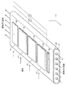
図1は、本発明の実施形態に係る固体酸化物形燃料電池(SOFC)の構造体を示す。このSOFCの構造体は、長手方向(x軸方向)を有する平板状の支持基板10の上下面(互いに平行な両側の主面(平面))のそれぞれに、電気的に直列に接続された複数(本例では、4つ)の同形の発電素子部Aが長手方向において所定の間隔をおいて配置された、所謂「横縞型」と呼ばれる構成を有する。
(Constitution)
FIG. 1 shows a structure of a solid oxide fuel cell (SOFC) according to an embodiment of the present invention. This SOFC structure is electrically connected in series to the upper and lower surfaces (main surfaces (planes) on both sides parallel to each other) of the
このSOFCの構造体の全体を上方からみた形状は、例えば、長手方向の辺の長さが50〜500mmで長手方向に直交する幅方向(y軸方向)の長さが10〜100mmの長方形である。このSOFCの構造体の全体の厚さは、1〜5mmである。このSOFCの構造体の全体は、厚さ方向の中心を通り且つ支持基板10の主面に平行な面に対して上下対称の形状を有する。以下、図1に加えて、このSOFCの構造体の図1に示す2−2線に対応する部分断面図である図2を参照しながら、このSOFCの構造体の詳細について説明する。図2は、代表的な1組の隣り合う発電素子部A,Aのそれぞれの構成(の一部)、並びに、発電素子部A,A間の構成を示す部分断面図である。その他の組の隣り合う発電素子部A,A間の構成も、図2に示す構成と同様である。
The shape of the entire SOFC structure as viewed from above is, for example, a rectangle having a length of 50 to 500 mm in the longitudinal direction and a length in the width direction (y-axis direction) perpendicular to the longitudinal direction of 10 to 100 mm. is there. The total thickness of the SOFC structure is 1 to 5 mm. The entire SOFC structure has a vertically symmetrical shape with respect to a plane passing through the center in the thickness direction and parallel to the main surface of the
支持基板10は、電子伝導性を有さない多孔質の材料からなる平板状の焼成体である。後述する図6に示すように、支持基板10の内部には、長手方向に延びる複数(本例では、6本)の燃料ガス流路11(貫通孔)が幅方向において所定の間隔をおいて形成されている。本例では、各凹部12は、支持基板10の材料からなる底壁と、全周に亘って支持基板10の材料からなる周方向に閉じた側壁(長手方向に沿う2つの側壁と幅方向に沿う2つの側壁)と、で画定された直方体状の窪みである。
The
支持基板10は、例えば、CSZ(カルシア安定化ジルコニア)から構成され得る。或いは、NiO(酸化ニッケル)とYSZ(8YSZ)(イットリア安定化ジルコニア)とから構成されてもよいし、NiO(酸化ニッケル)とY2O3(イットリア)とから構成されてもよいし、MgO(酸化マグネシウム)とMgAl2O4(マグネシアアルミナスピネル)とから構成されてもよい。
The
支持基板10は、「遷移金属酸化物又は遷移金属」と、絶縁性セラミックスとを含んで構成され得る。「遷移金属酸化物又は遷移金属」としては、NiO(酸化ニッケル)又はNi(ニッケル)が好適である。遷移金属は、燃料ガスの改質反応を促す触媒(炭化水素系のガスの改質触媒)として機能し得る。
The
また、絶縁性セラミックスとしては、MgO(酸化マグネシウム)、又は、「MgAl2O4(マグネシアアルミナスピネル)とMgO(酸化マグネシウム)の混合物」が好適である。また、絶縁性セラミックスとして、CSZ(カルシア安定化ジルコニア)、YSZ(8YSZ)(イットリア安定化ジルコニア)、Y2O3(イットリア)が使用されてもよい。 Further, as the insulating ceramic, MgO (magnesium oxide) or “mixture of MgAl 2 O 4 (magnesia alumina spinel) and MgO (magnesium oxide)” is preferable. Further, CSZ (calcia stabilized zirconia), YSZ (8YSZ) (yttria stabilized zirconia), Y 2 O 3 (yttria) may be used as the insulating ceramic.
このように、支持基板10が「遷移金属酸化物又は遷移金属」を含むことによって、改質前の残存ガス成分を含んだガスが多孔質の支持基板10の内部の多数の気孔を介して燃料ガス流路11から燃料極に供給される過程において、上記触媒作用によって改質前の残存ガス成分の改質を促すことができる。加えて、支持基板10が絶縁性セラミックスを含むことによって、支持基板10の絶縁性を確保することができる。この結果、隣り合う燃料極間における絶縁性が確保され得る。
As described above, since the
支持基板10の厚さは、1〜5mmである。支持基板10の気孔率は、後述する「還元処理」の後において20〜60%である。なお、以下、他の部材の気孔率の値も、還元処理後の値である。なお、気孔率の測定は,樹脂埋めしたサンプル(還元処理後)の断面を研磨し、同断面についてのSEM(走査型電子顕微鏡)による画像(2次電子像)を解析することによって行われた。SEMの加速電圧は5kV、SEMの倍率は5000倍、又は7500倍に設定された。気孔率の測定は、サンプルの任意の10箇所の断面について行われ、それらの平均値が気孔率の値として採用された。
The thickness of the
以下、この構造体の形状が上下対称となっていることを考慮し、説明の簡便化のため、支持基板10の上面側の構成についてのみ説明していく。支持基板10の下面側の構成についても同様である。
Hereinafter, only the configuration on the upper surface side of the
図2及び図3に示すように、支持基板10の上面(上側の主面)に形成された各凹部12には、燃料極集電部21、燃料極活性部22、インターコネクタ30、及び、シール部35が埋設(充填)されている。
As shown in FIGS. 2 and 3, each
より具体的には、各凹部12において、燃料極集電部21の全体が、凹部12の底壁の全域、及び側壁の全域と接触するように、凹部12内に埋設されている。燃料極集電部21の上面には、凹部21aが形成されている。凹部21aは、燃料極集電部21の材料からなる底壁と、全周に亘って燃料極集電部21の材料からなる周方向に閉じた側壁(長手方向に沿う2つの側壁と幅方向に沿う2つの側壁)と、で画定された窪みである。この凹部21a内に(即ち、燃料極集電部21の上部に)、燃料極活性部22の全体、インターコネクタ30の全体、及び、シール部35の全体が埋設(充填)されている。
More specifically, in each
シール部35(四角の枠状を呈する)は、インターコネクタ30(直方体状(薄板状)を呈する)の側壁の全周、凹部21aの側壁の一部、及び、燃料極活性部22(直方体状(薄板状)を呈する)の側壁の一部、と接触するように、インターコネクタ30の側壁の周囲にて全周に亘って配置されている。即ち、シール部35のうちインターコネクタ30と燃料極活性部22との間に位置する部分は、燃料極活性部22と接触している。燃料極活性部22の側壁における前記一部以外の残りの部分は、凹部21aの側壁における前記一部以外の残りの部分と接触している。燃料極活性部22の底面の全域、インターコネクタ30の底面の全域、及び、シール部35の底面の全域は、燃料極集電部21(の凹部21aの底面)と接触している。
The seal portion 35 (presenting a rectangular frame shape) includes the entire circumference of the side wall of the interconnector 30 (presenting a rectangular parallelepiped shape (thin plate shape)), a part of the side wall of the
燃料極集電部21と燃料極活性部22とにより燃料極20が構成される。燃料極20(燃料極集電部21+燃料極活性部22)は、電子伝導性を有する多孔質の材料からなる焼成体である。
A
燃料極活性部22は、例えば、NiO(酸化ニッケル)とYSZ(8YSZ)(イットリア安定化ジルコニア)とから構成され得る。或いは、NiO(酸化ニッケル)とGDC(ガドリニウムドープセリア)とから構成されてもよい。燃料極集電部21は、例えば、NiO(酸化ニッケル)とYSZ(8YSZ)(イットリア安定化ジルコニア)とから構成され得る。或いは、NiO(酸化ニッケル)とY2O3(イットリア)とから構成されてもよいし、NiO(酸化ニッケル)とCSZ(カルシア安定化ジルコニア)とから構成されてもよい。燃料極活性部22の厚さは、5〜30μmであり、燃料極集電部21の厚さは、50〜500μmである。燃料極集電部21の気孔率は、25〜50%であり、燃料極活性部22の気孔率も、25〜50%である。
The fuel electrode
このように、燃料極集電部21は、電子伝導性を有する物質を含んで構成される。燃料極活性部22は、電子伝導性を有する物質と酸化性イオン(酸素イオン)伝導性を有する物質とを含んで構成される。燃料極活性部22における「気孔部分を除いた全体積に対する酸素イオン伝導性を有する物質の体積割合」は、燃料極集電部21における「気孔部分を除いた全体積に対する酸素イオン伝導性を有する物質の体積割合」よりも大きい。
As described above, the fuel electrode
インターコネクタ30は、電子伝導性を有する緻密な材料からなる焼成体である。インターコネクタ30は、例えば、ランタンクロマイト(LC)から構成され得る。ランタンクロマイトの化学式は、La1−xAxCr1−y−zByO3(ただし、A:Ca,Sr,Baから選択される少なくとも1種類の元素、B:Co,Ni,Mg,Alから選択される少なくとも1種類の元素、0.05≦x≦0.2、0.02≦y≦0.22、0≦z≦0.05)で表わされる。
The
或いは、インターコネクタ30は、チタン酸化物から構成され得る。チタン酸化物の化学式は、(A1−x,Bx)1−z(Ti1−y,Dy)O3(ただし、A:アルカリ土類元素から選択される少なくとも1種類の元素、B:Sc,Y,及びランタノイド元素から選択される少なくとも1種類の元素、D:第4周期、第5周期、第6周期の遷移金属、及びAl,Si,Zn,Ga,Ge,Sn,Sb,Pb,Biから選択される少なくとも1種類の元素、0≦x≦0.5、0≦y≦0.5、−0.05≦z≦0.05)で表わされる。この場合、(Sr,La)TiO3(ストロンチウムチタネート)から構成され得る。インターコネクタ30の厚さは、10〜100μmである。インターコネクタ30の気孔率は、10%以下である。
Alternatively, the
シール部35は、電気絶縁性を有する緻密な材料からなる焼成体である。シール部35は、例えば、金属酸化物を含有し、好ましくは金属酸化物を主成分とする。具体的には、上記金属酸化物として、(AE)ZrO3、MgO、MgAl2O4、及びCexLn1−xO2からなる群より選択される少なくとも1種類の酸化物を含有してもよい。ここで、AEは、アルカリ土類金属であり、Lnは、Y及びランタノイドからなる群より選択される少なくとも1種類の元素であり、xは0<x≦0.3を満たす。AEに該当する元素としては、Mg,Ca,Sr,及びBaが挙げられる。また、微量成分として、遷移金属酸化物(例えば、NiO、Mn3O4、Fe2O3、Cr2O3、CoO)が含まれても良い。これらの成分は、酸化物として存在していても良いし、上記「(AE)ZrO3、MgO、MgAl2O4、及びCexLn1−xO2からなる群より選択される少なくとも1種類の酸化物」に固溶する形で存在していても良い。金属酸化物の平均粒径は0.1〜5.0μmが好ましく、さらに好ましくは0.3〜4.0μmである。シール部35の厚さは、10〜100μmである。シール部35の気孔率は、10%以下である。
The
燃料極20(燃料極集電部21及び燃料極活性部22)の上面(外側面)と、インターコネクタ30の上面(外側面)と、シール部35の上面(外側面)と、支持基板10の主面とにより、1つの平面(凹部12が形成されていない場合の支持基板10の主面と同じ平面)が構成されている。即ち、燃料極20の上面とインターコネクタ30の上面とシール部35の上面と支持基板10の主面との間で、段差が形成されていない。
The upper surface (outer surface) of the fuel electrode 20 (the fuel electrode
燃料極20、インターコネクタ30、及びシール部35がそれぞれの凹部12に埋設された状態の支持基板10における長手方向に延びる外周面(主面を含む)において複数のシール部35及びインターコネクタ30に対応する部分を除いた全面は、固体電解質膜40により覆われている。より具体的には、図4に示すように、固体電解質膜40は、シール部35の外側面の周縁部の全周を覆うように、支持基板10の主面上に形成されている。この結果、シール部35とインターコネクタ30とが接触し、シール部35と固体電解質膜40とが接触する一方で、インターコネクタ30と固体電解質膜40とは接触していない。
A plurality of
固体電解質膜40は、イオン伝導性を有し且つ電子伝導性を有さない緻密な材料からなる焼成体である。固体電解質膜40は、例えば、YSZ(8YSZ)(イットリア安定化ジルコニア)から構成され得る。或いは、LSGM(ランタンガレート)から構成されてもよい。固体電解質膜40の厚さは、3〜50μmである。固体電解質膜40の気孔率は、10%以下である。
The
即ち、燃料極20がそれぞれの凹部12に埋設された状態の支持基板10における長手方向に延びる外周面の全面は、インターコネクタ30とシール部35と固体電解質膜40とからなる緻密層により覆われている。この緻密層は、緻密層の内側の空間を流れる燃料ガスと緻密層の外側の空間を流れる空気との混合を防止するガスシール機能を発揮する。
That is, the entire outer peripheral surface extending in the longitudinal direction of the
なお、図2に示すように、本例では、固体電解質膜40が平坦化されている。この結果、固体電解質膜40に段差が形成される場合に比して、応力集中に起因する固体電解質膜40でのクラックの発生が抑制され得、固体電解質膜40が有するガスシール機能の低下が抑制され得る。
As shown in FIG. 2, in this example, the
固体電解質膜40における各燃料極活性部22と接している箇所の上面には、反応防止膜50を介して空気極60が形成されている。反応防止膜50は、緻密な材料からなる焼成体であり、空気極60は、電子伝導性を有する多孔質の材料からなる焼成体である。反応防止膜50及び空気極60を上方からみた形状は、燃料極活性部22と略同一の長方形である。
An
反応防止膜50は、例えば、GDC=(Ce,Gd)O2(ガドリニウムドープセリア)から構成され得る。反応防止膜50の厚さは、3〜50μmである。空気極60は、例えば、LSCF=(La,Sr)(Co,Fe)O3(ランタンストロンチウムコバルトフェライト)から構成され得る。或いは、LSF=(La,Sr)FeO3(ランタンストロンチウムフェライト)、LNF=La(Ni,Fe)O3(ランタンニッケルフェライト)、LSC=(La,Sr)CoO3(ランタンストロンチウムコバルタイト)等から構成されてもよい。また、空気極60は、LSCFからなる第1層(内側層)とLSCからなる第2層(外側層)との2層によって構成されてもよい。空気極60の厚さは、10〜100μmである。
The
なお、反応防止膜50が介装されるのは、SOFC作製時又は作動中のSOFC内において固体電解質膜40内のYSZと空気極60内のSrとが反応して固体電解質膜40と空気極60との界面に電気抵抗が大きい反応層が形成される現象の発生を抑制するためである。
The
ここで、燃料極20と、固体電解質膜40と、反応防止膜50と、空気極60とが積層されてなる積層体が、「発電素子部A」に対応する(図2を参照)。即ち、支持基板10の上面には、複数(本例では、4つ)の発電素子部Aが、長手方向において所定の間隔をおいて配置されている。
Here, the laminated body formed by laminating the
各組の隣り合う発電素子部A,Aについて、一方の(図2では、左側の)発電素子部Aの空気極60と、他方の(図2では、右側の)発電素子部Aのインターコネクタ30とを跨ぐように、空気極60、固体電解質膜40、及び、インターコネクタ30の上面に、空気極集電膜70が形成されている。空気極集電膜70は、電子伝導性を有する多孔質の材料からなる焼成体である。空気極集電膜70を上方からみた形状は、長方形である。
For each pair of adjacent power generation element portions A and A, the
空気極集電膜70は、例えば、LSCF=(La,Sr)(Co,Fe)O3(ランタンストロンチウムコバルトフェライト)から構成され得る。或いは、LSC=(La,Sr)CoO3(ランタンストロンチウムコバルタイト)から構成されてもよい。或いは、Ag(銀)、Ag−Pd(銀パラジウム合金)から構成されてもよい。空気極集電膜70の厚さは、50〜500μmである。空気極集電膜70の気孔率は、20〜60%である。
The air electrode
このように各空気極集電膜70が形成されることにより、各組の隣り合う発電素子部A,Aについて、一方の(図2では、左側の)発電素子部Aの空気極60と、他方の(図2では、右側の)発電素子部Aの燃料極20(特に、燃料極集電部21)とが、電子伝導性を有する「空気極集電膜70及びインターコネクタ30」を介して電気的に接続される。この結果、支持基板10の上面に配置されている複数(本例では、4つ)の発電素子部Aが電気的に直列に接続される。ここで、電子伝導性を有する「空気極集電膜70及びインターコネクタ30」が前記「電気的接続部」に対応し、インターコネクタ30が前記「電気的接続部の第1部分」に対応し、空気極集電膜70が前記「電気的接続部の第2部分」に対応する。また、緻密な材料からなる「インターコネクタ30、シール膜35、及び、固体電解質膜40」が前記「ガスシール部」に対応する。なお、本願では、「緻密な材料」とは、ガスシール機能を有する程度に小さい気孔率を有する材料を指し、典型的には、その材料の気孔率が10%以下である。
By forming each air electrode
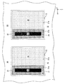
以上、説明した「横縞型」のSOFCの構造体に対して、図5に示すように、支持基板10の燃料ガス流路11内に燃料ガス(水素ガス等)を流すとともに、支持基板10の上下面(特に、各空気極集電膜70)を「酸素を含むガス」(空気等)に曝す(或いは、支持基板10の上下面に沿って酸素を含むガスを流す)ことにより、固体電解質膜40の両側面間に生じる酸素分圧差によって起電力が発生する。更に、この構造体を外部の負荷に接続すると、下記(1)、(2)式に示す化学反応が起こり、電流が流れる(発電状態)。
(1/2)・O2+2e−→O2− (於:空気極60) …(1)
H2+O2−→H2O+2e− (於:燃料極20) …(2)
As shown in FIG. 5, the fuel gas (hydrogen gas or the like) flows through the fuel
(1/2) · O 2 + 2e − → O 2− (where: air electrode 60) (1)
H 2 + O 2− → H 2 O + 2e − (in the fuel electrode 20) (2)
発電状態においては、図6に示すように、各組の隣り合う発電素子部A,Aについて、電流が、矢印で示すように流れる。この結果、図5に示すように、このSOFCの構造体全体から(具体的には、図5において最も手前側の発電素子部Aのインターコネクタ30と最も奥側の発電素子部Aの空気極60とを介して)電力が取り出される。
In the power generation state, as shown in FIG. 6, current flows as indicated by an arrow in each pair of adjacent power generation element portions A and A. As a result, as shown in FIG. 5, from the entire SOFC structure (specifically, in FIG. 5, the
(製造方法)
次に、図1に示した「横縞型」のSOFCの構造体の製造方法の一例について図7〜図16を参照しながら簡単に説明する。図7〜図16において、各部材の符号の末尾の「g」は、その部材が「焼成前」であることを表す。
(Production method)
Next, an example of a manufacturing method of the “horizontal stripe type” SOFC structure shown in FIG. 1 will be briefly described with reference to FIGS. 7 to 16, “g” at the end of the symbol of each member indicates that the member is “before firing”.
先ず、図7に示す形状を有する支持基板の成形体10gが作製される。この支持基板の成形体10gは、例えば、支持基板10の材料(例えば、CSZ)の粉末にバインダー等が添加されて得られるスラリーを用いて、押し出し成形、切削等の手法を利用して作製され得る。以下、図7に示す8−8線に対応する部分断面を表す図8〜図16を参照しながら説明を続ける。
First, a support substrate molded
図8に示すように、支持基板の成形体10gが作製されると、次に、図9に示すように、支持基板の成形体10gの上下面に形成された各凹部に、燃料極集電部の成形体21gがそれぞれ埋設・形成される。次いで、図10に示すように、各燃料極集電部の成形体21gの外側面に形成された凹部の一部に、燃料極活性部の成形体22gがそれぞれ埋設・形成される。各燃料極集電部の成形体21g、及び各燃料極活性部22gは、例えば、燃料極20の材料(例えば、NiとYSZ)の粉末にバインダー等が添加されて得られるスラリーを用いて、印刷法等を利用して埋設・形成される。
As shown in FIG. 8, when the support substrate molded
続いて、図11に示すように、各燃料極集電部の成形体21gの外側面に形成された前記凹部における前記一部以外の残りの部分の中央部に、直方体状のインターコネクタの成形体30gがそれぞれ埋設・形成される。各インターコネクタの成形体30gは、例えば、インターコネクタ30の材料(例えば、LaCrO3)の粉末にバインダー等が添加されて得られるスラリーを用いて、印刷法等を利用して埋設・形成される。
Subsequently, as shown in FIG. 11, a rectangular parallelepiped interconnector is formed at the central portion of the remaining portion other than the part of the concave portion formed on the outer surface of the molded
次いで、図12に示すように、前記凹部の成形体30gの周囲に位置する周縁部に、シール材の成形体35gがそれぞれ埋設・形成される。各シール材の成形体35gは、例えば、シール部35の材料(例えば、MgO、或いは、MgOとCaZrO3のコンポジット材料)の粉末にバインダー等が添加されて得られるスラリーを用いて、印刷法等を利用して埋設・形成される。
Next, as shown in FIG. 12, a molded
次に、図13に示すように、複数の燃料極の成形体(21g+22g)及び複数の成形体30g、35gがそれぞれ埋設・形成された状態の支持基板の成形体10gにおける長手方向に延びる外周面において複数の成形体30g、35gが形成されたそれぞれの部分を除いた全面に、固体電解質膜の成形膜40gが形成される。固体電解質膜の成形膜40gは、例えば、固体電解質膜40の材料(例えば、YSZ)の粉末にバインダー等が添加されて得られるスラリーを用いて、印刷法、ディッピング法等を利用して形成される。
Next, as shown in FIG. 13, the outer peripheral surface extending in the longitudinal direction in the molded
次に、図14に示すように、固体電解質膜の成形体40gにおける各燃料極の成形体22gと接している箇所の外側面に、反応防止膜の成形膜50gが形成される。各反応防止膜の成形膜50gは、例えば、反応防止膜50の材料(例えば、GDC)の粉末にバインダー等が添加されて得られるスラリーを用いて、印刷法等を利用して形成される。
Next, as shown in FIG. 14, a molded
そして、このように種々の成形膜が形成された状態の支持基板の成形体10gが、空気中にて1500℃で3時間焼成される。これにより、図1に示したSOFCの構造体において空気極60及び空気極集電膜70が形成されていない状態の構造体が得られる。
Then, 10 g of the support substrate molded body in which various molded films are thus formed is fired in air at 1500 ° C. for 3 hours. As a result, a structure in which the
次に、図15に示すように、各反応防止膜50の外側面に、空気極の成形膜60gが形成される。各空気極の成形膜60gは、例えば、空気極60の材料(例えば、LSCF)の粉末にバインダー等が添加されて得られるスラリーを用いて、印刷法等を利用して形成される。
Next, as shown in FIG. 15, an air
次に、図16に示すように、各組の隣り合う発電素子部について、一方の発電素子部の空気極の成形膜60gと、他方の発電素子部のインターコネクタ30とを跨ぐように、空気極の成形膜60g、固体電解質膜40、インターコネクタ30、及びシール部35の外側面に、空気極集電膜の成形膜70gが形成される。各空気極集電膜の成形膜70gは、例えば、空気極集電膜70の材料(例えば、LSCF)の粉末にバインダー等が添加されて得られるスラリーを用いて、印刷法等を利用して形成される。
Next, as shown in FIG. 16, for each pair of adjacent power generation element portions, air is formed so as to straddle the air
そして、このように成形膜60g、70gが形成された状態の支持基板10が、空気中にて1050℃で3時間焼成される。これにより、図1に示したSOFCの構造体が得られる。なお、この時点では、酸素含有雰囲気での焼成により、支持基板10、及び燃料極20中のNi成分が、NiOとなっている。従って、燃料極20の導電性を獲得するため、その後、支持基板10側から還元性の燃料ガスが流され、NiOが700〜1000℃で1〜100時間に亘って還元処理される。なお、この還元処理は発電時に行われてもよい。以上、図1に示したSOFCの構造体の製造方法の一例について説明した。
Then, the
(作用・効果)
上記実施形態では、「インターコネクタ30とシール部35と固体電解質膜40とが連続して接続されてなる緻密層」が、燃料ガスと空気との混合を防止するガスシール機能を発揮している。一般に、インターコネクタ(特に、ランタンクロマイトで構成されるインターコネクタ)は、上述した還元処理の際に膨張する性質を有する(還元膨張)。従って、インターコネクタの外側面の周縁部が電解質膜で覆われる構成では、この還元膨張に起因して、インターコネクタの外側面の周縁部と電解質膜の内側面との界面において剥離が発生し、「ガスシール機能」の低下が発生し易いという問題があった。これに対し、上記実施形態では、シール部35の外側面の一部(周縁部)が固体電解質膜40で覆われている一方で、インターコネクタ30の外側面は固体電解質膜40で覆われていない。従って、上述したインターコネクタの還元膨張による剥離に起因する「ガスシール機能」の低下が発生しない。即ち、「ガスシール機能」の低下を確実に抑制し得る。
(Action / Effect)
In the above embodiment, the “dense layer in which the
加えて、上記実施形態では、「シール部35のうちインターコネクタ30と燃料極活性部22との間に位置する部分」と、燃料極活性部22との間には、燃料極集電部21が介在しない。換言すれば、上記「発明の概要」の欄で述べた燃料電池と比べて、前記介在する燃料極集電部の上面の面積分だけ、燃料極活性部22の上面の面積を拡大することができる。この結果、「燃料極活性部22の上面に接触している固体電解質膜40」と燃料極活性部22との接触面積が大きくなり、燃料電池全体として発電効率が向上し得る。
In addition, in the above embodiment, the fuel electrode
本発明は上記実施形態に限定されることはなく、本発明の範囲内において種々の変形例を採用することができる。例えば、上記実施形態では、燃料電池を構成する積層体は、単独で存在しているが(図1を参照)、この積層体が、或る装置全体の一部分として存在していてもよい。また、上記実施形態では、図7等に示すように、支持基板10に形成された凹部12の平面形状(支持基板10の主面に垂直の方向からみた場合の形状)が、長方形になっているが、例えば、正方形、円形、楕円形、長穴形状等であってもよい。
The present invention is not limited to the above embodiment, and various modifications can be employed within the scope of the present invention. For example, in the above-described embodiment, the stack constituting the fuel cell exists alone (see FIG. 1), but this stack may exist as a part of an entire apparatus. Moreover, in the said embodiment, as shown in FIG. 7 etc., the planar shape (shape when it sees from the direction perpendicular | vertical to the main surface of the support substrate 10) of the recessed
また、上記実施形態においては、平板状の支持基板10の上下面のそれぞれに複数の凹部12が形成され且つ複数の発電素子部Aが設けられているが、図17に示すように、支持基板10の片側面のみに複数の凹部12が形成され且つ複数の発電素子部Aが設けられていてもよい。
Moreover, in the said embodiment, although the several recessed
10…支持基板、11…燃料ガス流路、12…凹部、20…燃料極、21…燃料極集電部、21a…凹部、22…燃料極活性部、30…インターコネクタ、35…シール部、40…固体電解質膜、50…反応防止膜、60…空気極、70…空気極集電膜、A…発電素子部
DESCRIPTION OF
Claims (2)
前記支持基板の主面における前記長手方向において互いに離れた複数の箇所にそれぞれ設けられ、少なくとも燃料極、固体電解質、及び空気極が積層されてなる複数の発電素子部と、
1組又は複数組の隣り合う前記発電素子部の間にそれぞれ設けられ、隣り合う前記発電素子部の一方の燃料極と他方の空気極とを電気的に接続する1つ又は複数の電気的接続部と、
前記燃料極に供給される第1のガスと前記空気極に供給される第2のガスとの混合を防止する緻密な構成材料からなるガスシール部と、
を備えた燃料電池において、
前記燃料極は、燃料極集電部と、前記燃料極集電部に対して酸素イオン伝導性を有する物質の含有割合が大きい燃料極活性部と、を含んで構成され、
前記各電気的接続部は、緻密な材料で構成された第1部分と、前記第1部分と接続され且つ多孔質の材料で構成された第2部分とで構成され、前記第1部分は、前記隣り合う発電素子部の一方の前記燃料極集電部と前記第2部分とに接続され、前記第2部分は、前記隣り合う発電素子部の他方の空気極と前記第1部分とに接続され、
前記ガスシール部は、前記発電素子部の一部としての緻密な前記固体電解質と、前記発電素子部の一部としての前記固体電解質から連続して延設された前記固体電解質と同じ緻密な構成材料からなる第1シール部と、前記第1シール部と接続されるとともに前記第1シール部とは異なる緻密な構成材料からなる第2シール部と、前記第2シール部と接続された前記電気的接続部の第1部分と、を含み、前記第1シール部と前記電気的接続部の第1部分とは接触しないように構成され、
前記支持基板の主面における前記複数の箇所に、前記支持基板の材料からなる底壁と、前記支持基板の材料からなる側壁と、を有する第1凹部がそれぞれ形成され、
前記各第1凹部に、対応する前記発電素子部の前記燃料極集電部が、前記第1凹部の底壁の全域及び前記第1凹部の側壁の全域と接触するように埋設され、
前記埋設された各燃料極集電部の外側面に、前記支持基板の主面に垂直な方向からみたとき前記長手方向に沿う2辺を有する長方形を呈するとともに、前記燃料極集電部の材料からなる底壁と、前記燃料極集電部の材料からなる周方向に閉じた側壁と、を有する第2凹部がそれぞれ形成され、
前記各第2凹部において、
前記長手方向の一方側の領域に、対応する前記発電素子部の前記燃料極活性部が埋設され、前記各燃料極活性部の外側面は対応する前記発電素子部の一部としての前記固体電解質と接触しており、
前記長手方向の他方側の領域に、対応する前記第2シール部及び前記電気的接続部の第1部分が埋設され、
前記第2シール部が、前記電気的接続部の第1部分の側壁の全周と接触するように、前記電気的接続部の第1部分の側壁の周囲にて全周に亘って配置され、
前記第2シール部のうち前記電気的接続部の第1部分と前記燃料極活性部との間に位置する部分が、前記燃料極活性部と接触している、燃料電池。 A support substrate having a longitudinal direction in which a gas flow path is formed;
A plurality of power generating element portions each provided at a plurality of locations separated from each other in the longitudinal direction on the main surface of the support substrate; and a stack of at least a fuel electrode, a solid electrolyte, and an air electrode;
One or a plurality of electrical connections that are respectively provided between one or a plurality of adjacent power generation element portions and electrically connect one fuel electrode and the other air electrode of the adjacent power generation element portions. And
A gas seal portion made of a dense constituent material that prevents mixing of the first gas supplied to the fuel electrode and the second gas supplied to the air electrode;
In a fuel cell comprising
The fuel electrode includes a fuel electrode current collector, and a fuel electrode active part having a large content ratio of a substance having oxygen ion conductivity with respect to the fuel electrode current collector,
Each of the electrical connection portions includes a first portion made of a dense material and a second portion connected to the first portion and made of a porous material. Connected to one of the fuel electrode current collectors and the second part of the adjacent power generation element part, and the second part is connected to the other air electrode and the first part of the adjacent power generation element part And
The gas seal part has the same dense structure as the solid electrolyte as a part of the power generation element part and the solid electrolyte continuously extended from the solid electrolyte as a part of the power generation element part A first seal portion made of a material; a second seal portion made of a dense constituent material that is connected to the first seal portion and is different from the first seal portion; and the electric power connected to the second seal portion. A first portion of the electrical connection portion, and configured so as not to contact the first seal portion and the first portion of the electrical connection portion,
First recesses having a bottom wall made of the material of the support substrate and a side wall made of the material of the support substrate are formed in the plurality of locations on the main surface of the support substrate, respectively.
In each of the first recesses, the fuel electrode current collector of the corresponding power generation element unit is embedded so as to be in contact with the entire bottom wall of the first recess and the entire sidewall of the first recess.
The outer surface of each buried fuel electrode current collector has a rectangular shape having two sides along the longitudinal direction when viewed from the direction perpendicular to the main surface of the support substrate, and the material for the fuel electrode current collector Second recesses each having a bottom wall made of and a circumferentially closed side wall made of the material of the fuel electrode current collector,
In each of the second recesses,
The fuel electrode active part of the corresponding power generation element part is embedded in a region on one side in the longitudinal direction, and the outer surface of each fuel electrode active part is the solid electrolyte as a part of the corresponding power generation element part In contact with
In the region on the other side in the longitudinal direction, the corresponding second seal portion and the first portion of the electrical connection portion are embedded,
The second seal portion is arranged over the entire circumference around the side wall of the first portion of the electrical connection portion so as to contact the entire circumference of the side wall of the first portion of the electrical connection portion,
The fuel cell, wherein a portion of the second seal portion located between the first portion of the electrical connection portion and the anode active portion is in contact with the anode active portion.
前記各第1凹部において、
前記第2シール部の外側面の周縁部の全周が前記第1シール部で覆われている、燃料電池。 The fuel cell according to claim 1, wherein
In each of the first recesses,
The fuel cell, wherein the entire periphery of the outer peripheral surface of the second seal portion is covered with the first seal portion.
Priority Applications (1)
| Application Number | Priority Date | Filing Date | Title |
|---|---|---|---|
| JP2013196444A JP5613808B1 (en) | 2013-09-24 | 2013-09-24 | Fuel cell |
Applications Claiming Priority (1)
| Application Number | Priority Date | Filing Date | Title |
|---|---|---|---|
| JP2013196444A JP5613808B1 (en) | 2013-09-24 | 2013-09-24 | Fuel cell |
Publications (2)
| Publication Number | Publication Date |
|---|---|
| JP5613808B1 true JP5613808B1 (en) | 2014-10-29 |
| JP2015064931A JP2015064931A (en) | 2015-04-09 |
Family
ID=52574677
Family Applications (1)
| Application Number | Title | Priority Date | Filing Date |
|---|---|---|---|
| JP2013196444A Expired - Fee Related JP5613808B1 (en) | 2013-09-24 | 2013-09-24 | Fuel cell |
Country Status (1)
| Country | Link |
|---|---|
| JP (1) | JP5613808B1 (en) |
Cited By (2)
| Publication number | Priority date | Publication date | Assignee | Title |
|---|---|---|---|---|
| US9755249B2 (en) | 2014-09-30 | 2017-09-05 | Toto Ltd. | Solid oxide fuel cell stack |
| US10003088B2 (en) | 2014-09-30 | 2018-06-19 | Toto Ltd. | Solid oxide fuel cell stack |
Citations (2)
| Publication number | Priority date | Publication date | Assignee | Title |
|---|---|---|---|---|
| JP2009245687A (en) * | 2008-03-31 | 2009-10-22 | Dainippon Printing Co Ltd | Solid oxide fuel cell and method of manufacturing solid oxide fuel cell |
| JP5116184B1 (en) * | 2011-10-25 | 2013-01-09 | 日本碍子株式会社 | Fuel cell structure |
-
2013
- 2013-09-24 JP JP2013196444A patent/JP5613808B1/en not_active Expired - Fee Related
Patent Citations (2)
| Publication number | Priority date | Publication date | Assignee | Title |
|---|---|---|---|---|
| JP2009245687A (en) * | 2008-03-31 | 2009-10-22 | Dainippon Printing Co Ltd | Solid oxide fuel cell and method of manufacturing solid oxide fuel cell |
| JP5116184B1 (en) * | 2011-10-25 | 2013-01-09 | 日本碍子株式会社 | Fuel cell structure |
Cited By (2)
| Publication number | Priority date | Publication date | Assignee | Title |
|---|---|---|---|---|
| US9755249B2 (en) | 2014-09-30 | 2017-09-05 | Toto Ltd. | Solid oxide fuel cell stack |
| US10003088B2 (en) | 2014-09-30 | 2018-06-19 | Toto Ltd. | Solid oxide fuel cell stack |
Also Published As
| Publication number | Publication date |
|---|---|
| JP2015064931A (en) | 2015-04-09 |
Similar Documents
| Publication | Publication Date | Title |
|---|---|---|
| JP4850980B1 (en) | Fuel cell structure | |
| JP5116184B1 (en) | Fuel cell structure | |
| JP6169930B2 (en) | Solid oxide fuel cell | |
| JP2014225434A (en) | Fuel cell | |
| JP4824137B1 (en) | Fuel cell structure | |
| JP5443648B1 (en) | Fuel cell structure | |
| JP6158659B2 (en) | Solid oxide fuel cell | |
| JP5642855B1 (en) | Fuel cell | |
| JP4846061B1 (en) | Fuel cell structure | |
| JP5613808B1 (en) | Fuel cell | |
| JP5075268B1 (en) | Fuel cell structure | |
| JP6169932B2 (en) | Solid oxide fuel cell | |
| JP5417548B2 (en) | Fuel cell structure | |
| JP6063368B2 (en) | Fuel cell | |
| JP5752297B1 (en) | Fuel cell | |
| JP5732180B1 (en) | Fuel cell | |
| JP5621029B1 (en) | Fuel cell | |
| JP5714738B1 (en) | Fuel cell | |
| JP5062786B1 (en) | Fuel cell structure | |
| JP5122676B1 (en) | Fuel cell structure | |
| JP4824136B1 (en) | Fuel cell structure | |
| JP5587479B1 (en) | Fuel cell | |
| JP6039461B2 (en) | Solid oxide fuel cell | |
| JP5753930B1 (en) | Fuel cell | |
| JP6039463B2 (en) | Solid oxide fuel cell |
Legal Events
| Date | Code | Title | Description |
|---|---|---|---|
| TRDD | Decision of grant or rejection written | ||
| A01 | Written decision to grant a patent or to grant a registration (utility model) |
Free format text: JAPANESE INTERMEDIATE CODE: A01 Effective date: 20140902 |
|
| R150 | Certificate of patent or registration of utility model |
Ref document number: 5613808 Country of ref document: JP Free format text: JAPANESE INTERMEDIATE CODE: R150 |
|
| LAPS | Cancellation because of no payment of annual fees |