JP5555621B2 - Calibration of a radiometric optical monitoring system used for fault detection and process monitoring - Google Patents
Calibration of a radiometric optical monitoring system used for fault detection and process monitoring Download PDFInfo
- Publication number
- JP5555621B2 JP5555621B2 JP2010507442A JP2010507442A JP5555621B2 JP 5555621 B2 JP5555621 B2 JP 5555621B2 JP 2010507442 A JP2010507442 A JP 2010507442A JP 2010507442 A JP2010507442 A JP 2010507442A JP 5555621 B2 JP5555621 B2 JP 5555621B2
- Authority
- JP
- Japan
- Prior art keywords
- spectrometer
- light source
- calibration
- light
- chamber
- Prior art date
- Legal status (The legal status is an assumption and is not a legal conclusion. Google has not performed a legal analysis and makes no representation as to the accuracy of the status listed.)
- Active
Links
Images


Classifications
-
- G—PHYSICS
- G01—MEASURING; TESTING
- G01J—MEASUREMENT OF INTENSITY, VELOCITY, SPECTRAL CONTENT, POLARISATION, PHASE OR PULSE CHARACTERISTICS OF INFRARED, VISIBLE OR ULTRAVIOLET LIGHT; COLORIMETRY; RADIATION PYROMETRY
- G01J3/00—Spectrometry; Spectrophotometry; Monochromators; Measuring colours
- G01J3/28—Investigating the spectrum
- G01J3/443—Emission spectrometry
-
- G—PHYSICS
- G01—MEASURING; TESTING
- G01J—MEASUREMENT OF INTENSITY, VELOCITY, SPECTRAL CONTENT, POLARISATION, PHASE OR PULSE CHARACTERISTICS OF INFRARED, VISIBLE OR ULTRAVIOLET LIGHT; COLORIMETRY; RADIATION PYROMETRY
- G01J3/00—Spectrometry; Spectrophotometry; Monochromators; Measuring colours
- G01J3/02—Details
-
- G—PHYSICS
- G01—MEASURING; TESTING
- G01J—MEASUREMENT OF INTENSITY, VELOCITY, SPECTRAL CONTENT, POLARISATION, PHASE OR PULSE CHARACTERISTICS OF INFRARED, VISIBLE OR ULTRAVIOLET LIGHT; COLORIMETRY; RADIATION PYROMETRY
- G01J3/00—Spectrometry; Spectrophotometry; Monochromators; Measuring colours
- G01J3/28—Investigating the spectrum
- G01J2003/2866—Markers; Calibrating of scan
Landscapes
- Physics & Mathematics (AREA)
- Spectroscopy & Molecular Physics (AREA)
- General Physics & Mathematics (AREA)
- Spectrometry And Color Measurement (AREA)
- Investigating, Analyzing Materials By Fluorescence Or Luminescence (AREA)
- Investigating Or Analysing Materials By Optical Means (AREA)
Description
本発明は、一般に、正確な光放射分光測定を得ることに関する。より詳しくは、本発明は、障害検出及びプロセスモニタリングにおいて利用される分光装置の放射分析キャリブレーションのためのシステム及び方法に関する。 The present invention generally relates to obtaining accurate optical emission spectrometry measurements. More particularly, the present invention relates to a system and method for radiometric calibration of spectroscopic devices utilized in fault detection and process monitoring.
この出願は、共に本発明の譲渡人に譲渡された、2007年5月7日に提出の共に係属中の米国仮出願番号第60/928377号、発明の名称「障害検出及びプロセスモニタリングのために使用される放射分析光学モニタリングシステムのキャリブレーション」、及び、2008年4月18日提出の共に係属中の米国仮出願番号第61/045585号、発明の名称「障害検出及びプロセスモニタリングのための放射分析光学モニタリングシステムのキャリブレーション」に関係し、その利益を求める。上記に認証された出願は、参照によってその全てがここに組み入れられる。 This application is assigned to the assignee of the present invention and is co-pending US Provisional Application No. 60/926377, filed May 7, 2007, entitled "For Fault Detection and Process Monitoring." "Calibration of the radiometric optical monitoring system used" and US Provisional Application No. 61/045585, filed April 18, 2008, entitled "Radiation for Fault Detection and Process Monitoring" Benefits related to “calibration of analytical optical monitoring system”. All of the above-certified applications are hereby incorporated by reference.
半導体加工の技術において、ウェハから集積回路構造を構成するために、選択的に、材料を取り除き、半導体ウェハ上に配置することがよく知られている。半導体ウェハからの材料の除去は、例えば、反応性イオンエッチング、ディープイオンエッチング、及びスパッタリングエッチング、及びプラズマエッチングを含むいくつかの種類のエッチング処理を採用することによって達成される。材料をウェアに配置することは、化学的な及び物理的な蒸着、蒸発処理、電子ビーム物理的気相成長法、スパッタリング蒸着、パルスレーザー蒸着、分子線エピタキシー及び高速酸素蒸着を含む。他の除去及び蒸着処理が既知である。そのような処理は、シールドプロセスチャンバ内でしっかりと制御される。正確な材料の量が、ウェハ基板上に配置され又はウェハ基板から除去されるという理由から、その進行は、停止時間又は特定のプロセスのエンドポイントを正確に決定するために、連続的に及び正確にモニタされなければならない。チャンバ処理を光学的にモニタすることは、進行中の処理のためのステージ又はエンドポイントのための1つの有用なツールである。例えば、チャンバの内部は、放射され又はチャンバ内でターゲットから反射される光の所定の波長のスペクトル解析によって、特定の既知の放射ラインについて光学的にモニタされ得る。典型的な方法は、発光分光法(OES)、吸収分光法、反射率測定法等である。典型的に、光学センサ又は光源が、チャンバの外部上に配置され、及び、観察されるチャンバ内のターゲットエリアに対する有利な点とともに、ビューポイント又はウィンドウに近接して配置される。 In semiconductor processing techniques, it is well known to selectively remove material and place it on a semiconductor wafer to construct an integrated circuit structure from the wafer. Removal of material from the semiconductor wafer is accomplished by employing several types of etching processes including, for example, reactive ion etching, deep ion etching, and sputtering etching, and plasma etching. Placing the material in the wear includes chemical and physical vapor deposition, evaporation processes, electron beam physical vapor deposition, sputtering vapor deposition, pulsed laser vapor deposition, molecular beam epitaxy and rapid oxygen vapor deposition. Other removal and deposition processes are known. Such processing is tightly controlled within the shield process chamber. Because the exact amount of material is placed on or removed from the wafer substrate, its progression is continuous and accurate to accurately determine the downtime or end point of a particular process. Must be monitored. Optically monitoring chamber processing is one useful tool for a stage or endpoint for ongoing processing. For example, the interior of the chamber can be optically monitored for a particular known radiation line by spectral analysis of a predetermined wavelength of light that is emitted or reflected from a target within the chamber. Typical methods are emission spectroscopy (OES), absorption spectroscopy, reflectometry, and the like. Typically, an optical sensor or light source is placed on the exterior of the chamber and placed in close proximity to the viewpoint or window, with advantages for the target area in the chamber being observed.
光学モニタリングチャンバプロセスの1つの問題は、多くのこれらのプロセスの間に絶対値を正確に測定することが、難しく又は不可能であるということである。これは、主として、光学経路内の汚染物の蓄積、例えば、光学測定が行われるビューポートウィンドウによるものである。それ故、従来技術において既知のキャリブレーションプロセスは、大きな範囲で、主としてこれらの未解決の問題を考慮して発展してきた。分光器とその関係する分光検出器がブロードバンドキャリブレーションスタンダードを使用するその全体のスペクトル範囲で検査する(キャリブレートする)ことが可能である一方で、ビューポートウィンドウがほとんどすぐに曇り始め、それによって、その後の光学測定の精度を減少させるということから、その精度のレベルが、時々、過度に考慮される。光学ビューポートウィンドウが曇るので、時々、その透過が、分光器の全体のスペクトル範囲にわたってほぼ統一して影響を受けるということが考えられる。それ故、多くのウィンドウの曇りの欠点は、プロセス内の絶対値及び診断アルゴリズムに頼らないことでいくらか補償され得る。それ故、多くの測定プロセスは、絶対値の比較ではなく、相対的な値の比較を利用する。従来技術は、プロセスガス及びビューポートウィンドウ上の汚染物の効果の測定の精度に関する特定のスペクトルの測定の精度を強調する。 One problem with the optical monitoring chamber process is that it is difficult or impossible to accurately measure absolute values during many of these processes. This is mainly due to the accumulation of contaminants in the optical path, for example due to the viewport window in which optical measurements are made. Therefore, the calibration processes known in the prior art have evolved to a large extent primarily in view of these unresolved issues. While the spectrograph and its associated spectroscopic detector can be inspected (calibrated) over its entire spectral range using a broadband calibration standard, the viewport window begins to cloud almost immediately, thereby Since it reduces the accuracy of subsequent optical measurements, the level of accuracy is sometimes overly considered. As the optical viewport window becomes cloudy, it is sometimes considered that its transmission is affected almost uniformly over the entire spectral range of the spectrometer. Therefore, many window haze defects can be compensated somewhat by not relying on in-process absolute values and diagnostic algorithms. Therefore, many measurement processes utilize relative value comparisons rather than absolute value comparisons. The prior art emphasizes the accuracy of specific spectral measurements with respect to the accuracy of measurement of process gas and contaminant effects on the viewport window.
McAndrew, et al.に対する米国特許第5835230号、発明の名称「分光センサのキャリブレーションの方法」は、光線が測定セル内で内部の光学経路に沿って通過する光透過ウィンドウを伴う少なくとも1つの光のポート(又は光入口ポート及び光出口ポート)を伴う測定セルを利用するシステムを開示する。キャリブレーションシステムはまた、光出口ポートを通じてセルを出る光線を測定するための検出器と同様に、光入口ポートを通じてセル内を通過する光学チャンバを有する。ガス入口は、ガスの種類及び既知の濃度のキャリアガスを含むガスキャリブレーションガス流が光学チャンバ内に導入される光学チャンバに接続される。キャリブレーションガス流の分光測定は、それから実行される。キャリブレーションシステムを使用して、スペクトルのキャリブレーションが、特定のガスの種類及び様々な濃度のキャリアガスに関する分光器について実現され得る。 US Pat. No. 5,835,230 to McAndrew, et al., Entitled “Method of Calibrating a Spectroscopic Sensor”, describes at least one light with a light transmission window through which a light beam passes along an internal optical path in a measurement cell. A system utilizing a measurement cell with multiple ports (or light inlet and light outlet ports) is disclosed. The calibration system also has an optical chamber that passes through the cell through the light inlet port, as well as a detector for measuring light exiting the cell through the light outlet port. The gas inlet is connected to an optical chamber into which a gas calibration gas stream containing a gas type and a known concentration of carrier gas is introduced into the optical chamber. A spectroscopic measurement of the calibration gas flow is then performed. Using the calibration system, spectral calibration can be achieved for spectrographs for specific gas types and various concentrations of carrier gas.
Smith, et al.に対する米国特許6246473号、発明の名称「プラズマプロセッシング操作のための方法及び機器」は、プラズマチャンバ内におけるビューポートウィンドウの内側及び外側の面のin situ測定のための機器及びキャリブレーションスキームを開示する。機器は、もしあれば、プラズマプロセス中にプロセッシングチャンバから放射される光に面している、その効果を決定するためのウィンドウモニタリング又はキャリブレーションモジュールを有する。キャリブレーションは、プラズマプロセスにおいて得られる発光データに関係する波長シフト、強度シフト、又はその両方を是正することを意図している。本質的に、キャリブレーション装置は、2つの光学経路、ウィンドウを通じてプロセスチャンバの内部から放射される光を光学的にモニタリングする1つの経路、及び、ウィンドウの内部の面の状態を評価するためにキャリブレーション光源から反射される光を得るためのもう1つの経路、を有する。キャリブレーション光源(又は光源)は、外部に配置され、かつ、ウィンドウについて、透過比較を行うためにウィンドウの面の反射された検査された光を発射する。特許第5835230号及び特許6246473号は両方とも、それらの全部においてここで参照によって組み入れられる。 US Pat. No. 6,246,473 to Smith, et al., Entitled “Method and Instrument for Plasma Processing Operation”, describes an instrument and calibration for in situ measurements of the inside and outside surfaces of a viewport window in a plasma chamber. Disclosure scheme. The instrument has a window monitoring or calibration module to determine its effect, if any, facing the light emitted from the processing chamber during the plasma process. Calibration is intended to correct wavelength shifts, intensity shifts, or both related to emission data obtained in the plasma process. In essence, the calibration device is calibrated to evaluate two optical paths, one path for optically monitoring the light emitted from the interior of the process chamber through the window, and the condition of the internal surfaces of the window. Another path for obtaining light reflected from the light source. A calibration light source (or light source) is placed externally and emits reflected inspected light on the face of the window to make a transmission comparison for the window. Both patents 5835230 and 6246473 are hereby incorporated by reference in their entirety.
他の欠陥の中で、これらの参照の両方は、チャンバの内側から分光センサへの全体の光学経路に沿うシステムを検査することに関する問題を是正しない。さらに、従来のキャリブレーション技術は、局所的な一次標準キャリブレーション光源の使用に大きく依存する。 Among other deficiencies, both of these references do not correct the problems associated with inspecting the system along the entire optical path from inside the chamber to the spectroscopic sensor. Furthermore, conventional calibration techniques rely heavily on the use of local primary standard calibration light sources.
本発明は、障害検出及びプロセスモニタリングにおいて利用される放射分析分光装置を検査するためのシステム及び方法に導かれる。最初に、参照分光器が、剛性、安定性、及び運用設計要因のような様々な標準に基づいて選択される。初期のキャリブレーションステージにおいて、参照分光器の応答が、局所的な(近距離の)一次(主要な)標準に対して検査される(認識される標準に対してトレース可能(追跡可能、記録可能))な安定した検査された光源、又は代わりに、認識された標準に対してトレース可能である検査された光検出器に関して使用される検査されていない安定した光源)。主たる参照分光器は、少なくとも、光をスペクトル内に分散させるための分散要素、分光器からのスペクトル光を生の(検査されていない)スペクトル強度データに変換するための光検出器、及びプロセッシング能力(生のスペクトル強度データを検査されたデータに変換するためのソフトウェア、及び/又はファームウェア)を含む。分光器の光学経路におけるどの空気通路においても、光学経路におけるオゾンの蓄積を避けるために、酸素又は循環空気のパージがなされるべきである。典型的にランプ及び電力源を含む局所的な一次標準キャリブレーション光源は、どのタイプでもよいが、分光装置を検査するために設計され、そして、認識される標準(米国国立標準技術研究所(NIST)によって公表される標準仕様のような)に対してトレース可能な強度と精度を有するべきである。さらに、標準キャリブレーション光源は、実際に、特定の目的のために設計される2以上の分離した標準キャリブレーション光源であり得る。例えば、強度キャリブレーションを実行するための1以上の標準光源及び波長キャリブレーションを実行するための1以上の標準光源である。好ましくは、標準キャリブレーション光源の帯域幅は、参照分光器のスペクトル範囲を包囲するべきである。 The present invention is directed to a system and method for inspecting a radiometric spectrometer used in fault detection and process monitoring. Initially, a reference spectrometer is selected based on various standards such as stiffness, stability, and operational design factors. In the initial calibration stage, the response of the reference spectrometer is checked against the local (near-range) primary (primary) standard (traceable (trackable, recordable) against the recognized standard )) A stable inspected light source, or alternatively an uninspected stable light source used for an inspected photodetector that is traceable to a recognized standard). The main reference spectrometer is at least a dispersive element for dispersing light into the spectrum, a photodetector for converting spectral light from the spectrometer into raw (untested) spectral intensity data, and processing capabilities. (Software and / or firmware for converting raw spectral intensity data into examined data). In any air path in the optical path of the spectrometer, oxygen or circulating air should be purged to avoid ozone accumulation in the optical path. The local primary standard calibration light source, typically including a lamp and power source, can be of any type, but is a standard designed and recognized for inspecting spectroscopic instruments (NIST National Institute of Standards and Technology (NIST) It should have traceable strength and accuracy against (such as standard specifications published by). Further, the standard calibration light source may actually be two or more separate standard calibration light sources designed for a specific purpose. For example, one or more standard light sources for performing intensity calibration and one or more standard light sources for performing wavelength calibration. Preferably, the bandwidth of the standard calibration light source should encompass the spectral range of the reference spectrometer.
キャリブレーションフェイズの初期のステージは、典型的に、分光器の製造業者のサイトで実行されるが、代わりに、エンドユーザの位置で実行され、以下のように進行する。局所的な一次標準キャリブレーション光源からの光を受けることに応じて、生の分光データが参照分光器によってつくり出される。生の分光データを局所的な一次標準キャリブレーション光源について既知のスペクトルデータを比較することによって、参照出力補正係数の組が、参照分光器から引き出され得る。これらの参照出力補正係数は、生のスペクトルデータを、局所的な一次標準キャリブレーション光源の既知の強度に合う検査されたスペクトルデータに変換する出力アルゴリズムに関して使用される。一旦検査されると、参照分光器は、そのスペクトル範囲内のその光源についても定量的な分光測定をつくり出す。参照分光器はそれ故、第2の標準としての役割を果たす。 The initial stage of the calibration phase is typically performed at the spectrograph manufacturer's site, but instead is performed at the end user's location and proceeds as follows. In response to receiving light from a local primary standard calibration light source, raw spectroscopic data is generated by a reference spectrometer. By comparing the raw spectral data with known spectral data for the local primary standard calibration light source, a set of reference output correction factors can be derived from the reference spectrometer. These reference output correction factors are used for an output algorithm that converts the raw spectral data into examined spectral data that matches the known intensity of the local primary standard calibration light source. Once inspected, the reference spectrometer creates a quantitative spectroscopic measurement for the light source within its spectral range. The reference spectrometer therefore serves as a second standard.
次に、参照分光器の応答は、分離した光源に対して、1以上の製造分光器を検査するための第2の標準として使用される。参照分光器及び製造分光器は、製造参照光源からのスペクトル放射を受け、そして、光に応じて分離した出力をつくり出す。好ましくは、製造参照光源のスペクトル帯域は、製造分光器のスペクトル範囲を同様であるべきである。この光源は、キャリブレーション光源である必要はなく、その情報が参照分光器によって正確に測定されるという理由から、光の正確なスペクトル強度は既知である必要はない。参照及び製造分光器は、製造参照光源からの光を同時に受け、それによって、既知の強度の安定した光源についての要求を取り除くことが期待される。代わりに、もし、製造参照光源が、相対的に安定である場合、参照及び製造分光器は、連続的に取得され得る。製造分光器からの検査されていない出力は、参照分光器によってつくり出される検査された出力と比較される。その比較に基づいて、製造参照光源の既知の強度に対する生の出力を調整するための出力アルゴリズムに関して使用される製造分光器について、製造出力補正係数の組が引き出され得る。一旦検査されると、製造分光器は(参照分光器と同様に)、スペクトル範囲内のどの光源についても定量的な分光測定をつくり出すであろう。製造分光器のキャリブレーションが、標準的なキャリブレーション光源を使用することなく達成されることに留意すべきである。追加の製造分光器が、同様な方式で検査され得る。そうすることにおいて、本発明は、異なる分光器でつくり出されるスペクトルの比較を可能にし、何より、異なるが、検査される分光器を使用する異なるプロセスチャンバから得られる結果の定量的な比較を促進する。 The response of the reference spectrometer is then used as a second standard for inspecting one or more production spectrometers against a separate light source. The reference spectrometer and the production spectrometer receive spectral radiation from the production reference light source and produce a separate output in response to the light. Preferably, the spectral band of the manufacturing reference light source should be similar to the spectral range of the manufacturing spectrometer. This light source need not be a calibration light source, and the exact spectral intensity of the light need not be known because the information is accurately measured by the reference spectrometer. The reference and production spectrographs are expected to receive light from the production reference light source simultaneously, thereby eliminating the need for a stable light source of known intensity. Alternatively, if the production reference light source is relatively stable, the reference and production spectrometer can be acquired continuously. The uninspected output from the production spectrometer is compared to the inspected output produced by the reference spectrometer. Based on that comparison, a set of production output correction factors can be derived for the production spectrometer used in connection with the output algorithm to adjust the raw output for the known intensity of the production reference light source. Once inspected, the production spectrometer (similar to the reference spectrometer) will produce a quantitative spectroscopic measurement for any light source within the spectral range. It should be noted that calibration of the production spectrometer is accomplished without using a standard calibration light source. Additional production spectrometers can be examined in a similar manner. In doing so, the present invention allows the comparison of spectra produced by different spectrometers and, above all, facilitates a quantitative comparison of results obtained from different process chambers using different but examined spectrometers. To do.
所定のインターバルで、参照分光器のインテグリティは、局所的な一次標準に対してチェックされ、必要であれば、再検査されるべきである。キャリブレーション間の変化の量もまたチェックされ得る。もし、ドリフト量が、所定レベルの上である場合、参照分光器及び/又は標準キャリブレーション光源の安定性が懸念され、日常メンテナンスがキャリブレーションシステムに為されるべきである。 At a given interval, the integrity of the reference spectrometer should be checked against the local primary standard and rechecked if necessary. The amount of change between calibrations can also be checked. If the amount of drift is above a predetermined level, the stability of the reference spectrometer and / or standard calibration light source is a concern and routine maintenance should be performed on the calibration system.
本発明の他の実施形態によれば、製造分光器及び光学接続システムは、単独のユニットとして共に検査され得る。そうすることにおいて、分光器の応答は、光学接続システムの付加に起因し得るスループットにおけるどのような変化についても検査され得る。ここで再び、光学経路における全ての空気通路は、光学経路におけるオゾンの蓄積を避けるために酸素又は循環空気のパージが為されるべきである。もし、光ファイバが、接続システムに使用されると、ファイバは、製造チャンバとともに構成されるように、キャリブレーションについて同一に配置されるべきである。もし、初期のキャリブレーションステージ中に、製造形態が未知の場合には、その後、キャリブレーションに使用される光ファイバの配置が、記録され、そして、キャリブレーションデータとともに製造施設に送られ得る。この方法において、製造オペレータは、製造チャンバとともに光ファイバの配置を初期のキャリブレーションステージ中の配置を同じに構成できる。 According to other embodiments of the present invention, the production spectrometer and the optical connection system can be tested together as a single unit. In doing so, the response of the spectrometer can be examined for any change in throughput that may be due to the addition of an optical connectivity system. Here again, all air passages in the optical path should be purged of oxygen or circulating air to avoid ozone accumulation in the optical path. If an optical fiber is used in the connection system, the fiber should be placed identical for calibration so that it is configured with the manufacturing chamber. If during the initial calibration stage, the production form is unknown, then the placement of the optical fiber used for calibration can be recorded and sent to the production facility along with the calibration data. In this way, the manufacturing operator can configure the optical fiber arrangement with the manufacturing chamber to be the same as the arrangement in the initial calibration stage.
スループットにおける軽微な変化が、さらにプロセスチャンバに関する光ファイバの配送または再構成によって起こり得る。それ故、本発明のさらなるもう1つの望ましい実施形態によれば、単独のユニットとして共に最初に検査された製造分光器及び光学接続システムは、配送又は再構成の変化の量に対して微調整され得る。さらに、この微調整キャリブレーションステージはまた、プロセスチャンバに接続されているユニットに起因するスループットにおける変化の原因となるであろう。このキャリブレーションフェイズのステージは、通常、プラズマチャンバのオペレータによって、製造施設で実行されるということが予想される。ここで、初期のキャリブレーションステージからのキャリブレーションにおけるどのような変化も、分光器の全体のスペクトル範囲にわたって一定となるということが仮定され得る。それ故、単独の波長の光源(又は狭帯域光源)が十分であるべきである。好ましくは、もし、単独の波長が利用されると、実行されるプロセス測定において有用であるスペクトル範囲の一部内にその波長が存在するように、光源が選択されるべきである。分光器によって検出されるウィンドウを光が通過しなければならないようにすべく、単独の波長光源を配置することによって、微調整キャリブレーションステージが開始する。キャリブレーション結果が、異なるチャンバで自由に複製され得るようにすべく、光源が各プロセスチャンバにおいて同じ位置に配置されるべきである。再生可能な配列を補償するための1つのメカニズムは、配置のために光源とともに、配列/位置決めジグを使用することによるものである。繰り返し可能な結果を補償するためのもう1つのメカニズムは、所定の位置において、ビューポートウィンドウに対するプロセスチャンバの反対の壁部に配置される光源を取り外せないように収容するための光チャンバを作り出すことである。光チャンバは、光源を保護するための光チャンバウィンドウを有すべきであり、さらに、プラズマ及びプロセスチャンバ内に現れる他の汚染物の有害な効果から光チャンバを保護するためにプロセス中に閉じられ得るシャッタを含むべきである。 Minor changes in throughput can also occur due to optical fiber delivery or reconfiguration with respect to the process chamber. Therefore, according to yet another preferred embodiment of the present invention, the production spectrograph and optical connection system that were first inspected together as a single unit are fine-tuned for the amount of change in delivery or reconfiguration. obtain. Furthermore, this fine tuning calibration stage will also account for changes in throughput due to the units connected to the process chamber. It is expected that this stage of the calibration phase is usually performed at the manufacturing facility by the operator of the plasma chamber. Here, it can be assumed that any change in calibration from the initial calibration stage is constant over the entire spectral range of the spectrometer. Therefore, a single wavelength light source (or narrowband light source) should be sufficient. Preferably, if a single wavelength is utilized, the light source should be selected such that the wavelength is within a portion of the spectral range that is useful in the process measurement being performed. The fine tuning calibration stage begins by placing a single wavelength light source so that the light must pass through the window detected by the spectrometer. The light source should be placed at the same location in each process chamber so that the calibration results can be freely replicated in different chambers. One mechanism for compensating a reproducible array is by using an array / positioning jig with a light source for placement. Another mechanism to compensate for repeatable results is to create a light chamber in place to accommodate unremovable light sources located on the opposite wall of the process chamber relative to the viewport window. It is. The light chamber should have a light chamber window to protect the light source and be closed during the process to protect the light chamber from the harmful effects of plasma and other contaminants that appear in the process chamber. Should include a shutter to obtain.
代わりに、及び本発明のさらなるもう1つの望ましい実施形態にしたがって、上述された分光器のキャリブレーションは、製造施設で全体的に達成され得る。したがって、製造分光器は、光学接続システムを経由してプロセスチャンバに接続される。ここで、目的は、製造のために分光器を検査するだけでなく、プロセスチャンバ内からの一部を含み、分光器に関する光学システムのどの部分によっても引き起こされるスループットにおけるどのような変化についても分光器を検査することである。プラズマ光がチャンバビューポートウィンドウについて最も見えやすくなる(又は分離した光源チャンバ内でプロセスチャンバに近接する)位置で、プロセスチャンバ内に局所的な一次標準キャリブレーション光源を最初に配置することによって、キャリブレーションは、一般に上記のように進行する。分光器、光学接続システム、及びプロセスチャンバは、その後、一般に上記のように、局所的な一次標準に対して検査される。プロセスは、分離したプロセスチャンバに接続される各分光器について繰り返され得る。結果として、分離した分光器は、その後、局所的な一次標準に対して検査されることとなるが、それらのキャリブレーションは、プロセスチャンバ内の一部を含み、分光器に関する光学システムのどの部分よっても引き起こされるスループットにおける変化の原因となる。 Alternatively, and in accordance with yet another preferred embodiment of the present invention, the calibration of the spectrometer described above may be accomplished entirely at the manufacturing facility. Thus, the production spectrometer is connected to the process chamber via an optical connection system. Here, the objective is not only to inspect the spectrometer for manufacturing, but also to spectroscopically analyze any changes in throughput, including parts from within the process chamber, caused by any part of the optical system associated with the spectrometer. Is to inspect the vessel. Calibration by first placing a local primary standard calibration light source in the process chamber where the plasma light is most visible for the chamber viewport window (or close to the process chamber in a separate light source chamber) The process generally proceeds as described above. The spectrometer, optical connection system, and process chamber are then inspected against a local primary standard, generally as described above. The process can be repeated for each spectrometer connected to a separate process chamber. As a result, separate spectrometers will then be inspected against a local primary standard, but their calibration includes parts within the process chamber and any part of the optical system with respect to the spectrometer. This also causes the change in throughput caused.
オプションとして、参照分光器は、上記のように検査され、そして、参照分光器の応答は、他の分光器を検査するために使用され得る。最初に、参照分光器は、選択され、プロセスチャンバ内に配置されるか、又は、分離した光源チャンバ内でプロセスチャンバに近接して配置されるかのどちらかである局所的な一次標準キャリブレーション光源からの光を受けるためにプロセスチャンバに接続される。参照分光器の出力応答は、その後、次のキャリブレーションにおいて、異なる光源を伴う1以上の製造分光器を検査するための第2の標準として使用され得る。キャリブレーションのこの部分中に、製造参照光源が、局所的な一次標準キャリブレーション光源の代わりとなる。製造分光器は、参照分光器を共なるチャンバに光学的に接続される。好ましくは、製造分光器は、チャンバから光のスペクトルを監視するために使用されるように構成される。参照及び製造分光器は、製造光源からの光を同時に受ける。製造分光器の出力は、その後、上記のような参照分光器の応答に対して検査され得る。参照分光器は、その後、チャンバから外れ、上記のように製造参照光源のみを使用する他のチャンバに接続される他の製造分光器を検査するために使用され得る。各チャンバにおける参照分光器について、光ファイバ及び他の光学接続システムを同一に配置するための措置がとられるべきである。製造参照分光器のインテグリティは、参照ユニットをプロセスチャンバに接続し、その出力を同じ光源についてのプロセスチャンバの出力と比較することによって、第2の標準、参照分光器の出力に対して定期的にチェックされ得る。代わりに、全部のチャンバについて局所的な一次標準に対する1回のキャリブレーションだけに頼ることよりも、むしろ、参照分光器は、各チャンバについて局所的な一次標準キャリブレーション光源に対して再度検査され得る。その後、参照分光器から製造参照光源への検査された出力応答は、そのチャンバに接続される製造分光器を検査するために使用される。 Optionally, the reference spectrometer can be examined as described above, and the response of the reference spectrometer can be used to examine other spectrometers. Initially, a reference spectrometer is selected and placed in the process chamber or a local primary standard calibration that is either placed in a separate light source chamber and in close proximity to the process chamber. Connected to the process chamber for receiving light from the light source. The output response of the reference spectrometer can then be used as a second standard for inspecting one or more production spectrometers with different light sources in the next calibration. During this part of the calibration, the production reference light source replaces the local primary standard calibration light source. The production spectrometer is optically connected to the chamber that shares the reference spectrometer. Preferably, the production spectrometer is configured to be used to monitor the spectrum of light from the chamber. The reference and production spectrometer simultaneously receive light from the production light source. The output of the production spectrometer can then be checked against the response of the reference spectrometer as described above. The reference spectrometer can then be used to inspect other production spectrometers that are disconnected from the chamber and connected to other chambers that use only the production reference light source as described above. For the reference spectrometer in each chamber, measures should be taken to place the optical fiber and other optical connection systems identically. The integrity of the manufacturing reference spectrometer is periodically compared to the output of the second standard, the reference spectrometer, by connecting the reference unit to the process chamber and comparing its output to the process chamber output for the same light source. Can be checked. Instead, rather than relying on only one calibration to the local primary standard for all chambers, the reference spectrometer can be re-inspected against the local primary standard calibration light source for each chamber. . The inspected output response from the reference spectrometer to the production reference light source is then used to inspect the production spectrometer connected to that chamber.
代わりに、参照分光器及び製造分光器は、製造光源からの光を同時に受けることができない。そのような場合、参照分光器は、最初に、プロセスチャンバに光学的に接続され、そして、製造参照光源からの光を受ける。検査されたスペクトルデータが、参照分光器を使用するチャンバに関して集められ、そして、スペクトルデータの検査された出力が記録される。参照分光器は、その後、プロセスチャンバから取り除かれる。それらの測定は、今、製造参照光源を伴う製造分光器を検査するための第2の標準になる。検査されていない製造分光器は、プロセスチャンバに接続され、そして、製造参照光源からの光を受ける。その出力は、その後、参照分光器から記録されるスペクトルデータの検査された出力を使用して検査される。プロセスは、それから、異なる製造分光器について他のプロセスチャンバで繰り返され得る。 Instead, the reference spectrometer and the production spectrometer cannot receive light from the production light source simultaneously. In such a case, the reference spectrometer is first optically connected to the process chamber and receives light from the manufacturing reference light source. Inspected spectral data is collected for the chamber using the reference spectrometer and the inspected output of the spectral data is recorded. The reference spectrometer is then removed from the process chamber. Those measurements now become the second standard for inspecting production spectrometers with production reference light sources. An uninspected production spectrometer is connected to the process chamber and receives light from a production reference light source. That output is then inspected using the inspected output of the spectral data recorded from the reference spectrometer. The process can then be repeated in other process chambers for different production spectrometers.
本発明の特徴と信じられる新規な特徴が、添付の請求の範囲において説明される。本発明は、それ自体、しかしながら、望ましい使用のモード、さらに、そこでのさらなる目的と有利性と同様に、その添付の図面と併せて読んだときに、例示的な実施形態の以下の記述を参照することによって最も良く理解されるであろう。 The novel features believed characteristic of the invention are set forth in the appended claims. The present invention itself, however, refers to the following description of exemplary embodiments, when read in conjunction with the accompanying drawings, as well as the preferred modes of use, as well as further objects and advantages therein. Will be best understood.
本発明の他の特徴は、添付の図面及び以下の詳細な説明から明らかとなるであろう。 Other features of the present invention will be apparent from the accompanying drawings and from the detailed description that follows.
発光分光法は、プラズマの状態をモニタリングするための高感度技術である。しばしば、可能な限り近く、エッチング、蒸着、又は半導体産業における他の共通の目的のためのプラズマ環境を使用する工業プロセス内のようなプラズマ環境内の状態の組を再形成することが望ましい。それは、時々、多重プロセスチャンバ内において同一の状況をつくるのに有利である。代わりに、特定の従来の状態にプロセスチャンバを戻すための特定の環境において有用であり得る。発光分光法は、これを行うための手段を提供する。プラズマからの光の放射は、多くの明確な原子及び分子の状態からの貢献を包含する。これらの放射の独自性及び相対的な強度は、プラズマの正確な状態の高感度なインジケータである。それ故、所定の時間でプラズマチャンバからの光のスペクトルのこれらの様相をモニタリングし、記録することによって、少なくとも第1に、チャンバ、又は異なるチャンバでさえも後で調整し、光放射スペクトルの状態、そしてそれ故、プラズマの状態を再形成することが可能になる。 Emission spectroscopy is a highly sensitive technique for monitoring plasma conditions. Often it is desirable to recreate a set of conditions in a plasma environment, such as in an industrial process that uses the plasma environment for etching, deposition, or other common purposes in the semiconductor industry as close as possible. It is sometimes advantageous to create the same situation within a multi-process chamber. Instead, it may be useful in certain environments for returning the process chamber to certain conventional conditions. Emission spectroscopy provides a means for doing this. The emission of light from the plasma includes contributions from many distinct atomic and molecular states. The uniqueness and relative intensity of these emissions is a sensitive indicator of the exact state of the plasma. Therefore, by monitoring and recording these aspects of the spectrum of light from the plasma chamber at a given time, at least first, the chamber, or even a different chamber, can be adjusted later, and the state of the light emission spectrum And therefore it is possible to reshape the plasma state.
光放射スペクトルが、プラズマの状態に敏感に依存するという理由から、しばしば、いくつかの重要なプロセスパラメータの値が、光学スペクトル、特に、放射の強度から推測され得るということが発見される。それ故、光学スペクトルはまた、プラズマのコントロールのためのフィードバックシステムの部分、又は、いくつかの重要なプロセスパラメータを測定するためのツールとしての役割を果たし得る。 It is often found that the value of some important process parameters can be inferred from the optical spectrum, in particular the intensity of the radiation, because the light emission spectrum is sensitively dependent on the state of the plasma. Therefore, the optical spectrum can also serve as part of a feedback system for plasma control or as a tool for measuring some important process parameters.
しかしながら、これらの構成の実行に関する困難性が存在する。工業用プラズマツールにおける光学スペクトルを監視する慣習的な方法は、光検出器アレイに基づく光学分光器及び光をチャンバの内部のプラズマから分光器へと運ぶ光学カップリングシステムからなる。光学スペクトルは、狭スペクトル帯域の組において一連の光強度測定として記録される。困難性は、記録されたスペクトルが、プラズマによって放射された光の特性以外の要因に影響を受けるということである。これらは、光学カップリングシステムと同様に、波長及びスペクトルメータの強度キャリブレーション(検査)を含む。これらのアプリケーションにおいて採用されるスペクトルメータは、典型的に、同じ入力光源に曝されたときに、1つの応答が他のものに対応するように、検査される必要はない。もう1つの問題は、プラズマチャンバ内にあるウィンドウは、光の未知のわずかな量を吸収し、又はまき散らす汚染物でコートされてしまうことになり得るということである。もう1つの問題は、接続システムの他の効率が、セットアップにおいて避けられない摂動又は変化に応答して変化し得るということである。上記の目的のための光放射スペクトルモニタリングの潜在力の十分な有利性を得るために、記録されたスペクトル内で観測されたいかなる変化も、チャンバで起きた光の放射における実際の変化に起因し得るように、これらの外部からの影響を除外し、又は補償することが望ましい。 However, there are difficulties associated with performing these configurations. The conventional method of monitoring the optical spectrum in an industrial plasma tool consists of an optical spectrometer based on a photodetector array and an optical coupling system that carries light from the plasma inside the chamber to the spectrometer. The optical spectrum is recorded as a series of light intensity measurements in a set of narrow spectral bands. The difficulty is that the recorded spectrum is affected by factors other than the properties of the light emitted by the plasma. These include wavelength and spectrum meter intensity calibrations as well as optical coupling systems. Spectrometers employed in these applications typically do not need to be examined so that one response corresponds to the other when exposed to the same input light source. Another problem is that the window in the plasma chamber can be coated with contaminants that absorb or scatter an unknown small amount of light. Another problem is that other efficiencies of the connected system can change in response to inevitable perturbations or changes in the setup. In order to obtain the full advantage of light emission spectrum monitoring potential for the above purposes, any changes observed in the recorded spectrum are due to actual changes in the light emission occurring in the chamber. It is desirable to eliminate or compensate for these external influences so that they can be obtained.
これらの外部からの影響を除外し又は少なくとも定量化する1つの試みは、Smithに対する米国特許第6246473号に開示される。そこでは、プロセスチャンバの外部にある光源が、例えば、ウィンドウの曇りによって起こる変化を補償するために、分光器、光接続システム、又はその両方を検査するために使用される。キャリブレーション装置は、2つの光学経路、1つの経路が、ウィンドウを通じて光学測定を行うためのもの、もう1つの経路が、ウィンドウの表面を反射する外部のキャリブレーション光源を使用するウィンドウの内部表面の状態を評価するためのもの、を有する。第2の光学経路は、プロセスチャンバの外部にある1以上のキャリブレーション光源で終わる。この方法論の1つの利益は、分光器に対する光学ビューポートウィンドウの内部表面の少なくともスループット(処理量)に関して、チャンバの状態が、キャリブレーション光源に対して調整可能で、そしてそれから、未来の状態が初期のキャリブレーション測定と比較され得るということである。ビューポートウィンドウによって起こる透過における変化が、認識され、そして、製造中に光学測定を調整するために使用されるキャリブレーション状態と比較される。この方法は、スループット経路の状態を確立するための外部のキャリブレーション光源に依存する。 One attempt to eliminate or at least quantify these external effects is disclosed in US Pat. No. 6,246,473 to Smith. There, a light source external to the process chamber is used to inspect the spectrometer, the optical connection system, or both, for example to compensate for changes caused by window fogging. The calibration device has two optical paths, one for making optical measurements through the window, and another path for the internal surface of the window that uses an external calibration light source that reflects the surface of the window. For assessing the condition. The second optical path ends with one or more calibration light sources external to the process chamber. One benefit of this methodology is that the chamber state is adjustable with respect to the calibration light source, at least with respect to the throughput of the internal surface of the optical viewport window for the spectrometer, and then the future state is initial. It can be compared with the calibration measurement. Changes in transmission caused by the viewport window are recognized and compared to the calibration state used to adjust the optical measurement during manufacturing. This method relies on an external calibration light source to establish the state of the throughput path.
必要とされるのは、同じチャンバから光学測定を比較することをオペレータに可能にするだけでなく、異なるチャンバから得られる測定と比較できるようにもする、これらの外部からの影響を是正するためのアプローチである。 What is needed is to correct these external effects that not only allow the operator to compare optical measurements from the same chamber, but also allow them to be compared with measurements obtained from different chambers. Is the approach.
本発明の一実施形態によれば、安定した光学分光器は、安定した光学接続システムに組み合わされ、そして、光学測定が任意に複製され得るように、関係する光学カップリングシステムのスループットと同様に、分光器の応答が検査される。分光器は、一定の入力光レベルについて、出力における変化が、チャンバからチャンバへの変化と比較して小さく、そして、プロセスの変化が安定しているという意味で安定しているべきである。適切な構成によって、分光器は、安定するように設計され得る。その構成の主な要素は、機械的剛性、検出器及び電気機器の温度安定性、及び紫外線光を検出するための蛍光体の使用の回避である。テキサス州、キャロルトンの Verity Instruments, Inc.から入手可能なSD1024分光器は、適した安定した分光器の一例である。光学測定を行うために半導体産業において共通して使用されるこの種の分光器は、一般に、少なくとも3つの機能的に分離した要素、スペクトル内に光を拡散させる光分散要素、特定の波長でのスペクトル強度を、強度の電気データに変換する光検出器、及び、プロセッシング能力、強度の電気データを検査されたデータに変換するためのソフトウェア及び/又はファームウェア、を含むということが理解され得る。それ故、典型的な分光器は、少なくとも1つの光学ポート、光学カプラ又は光を受ける他の光学要素、及び1以上のデータ接続、ポート、又はデータを送受信し、プログラムコードを実行可能な他のデータ伝達要素を含むであろう。以下に、これらの要素が分光器と一緒に参照されるであろう。また、いくつかの文脈において、分光器の用語が、分光器と検出器との組あわせとして理解されるだけでなく、他の文脈において、2つが分離した機器として考えられるということも理解されるべきである。検出器の正確な選択が、記録されるべき光の波長に依存するということから、用語の使用は、ここで、分離される分光器と検出器の能力を受け入れる。 According to one embodiment of the present invention, a stable optical spectrometer is combined with a stable optical connection system, and the throughput of the associated optical coupling system is such that optical measurements can be arbitrarily replicated. The spectrometer response is examined. The spectrometer should be stable in the sense that for a given input light level, the change in output is small compared to the change from chamber to chamber, and the process change is stable. With proper configuration, the spectrometer can be designed to be stable. The main elements of its construction are mechanical rigidity, temperature stability of detectors and electrical equipment, and avoidance of the use of phosphors to detect ultraviolet light. The SD1024 spectrometer available from Verity Instruments, Inc. of Carrollton, Texas is an example of a suitable stable spectrometer. Commonly used in the semiconductor industry to make optical measurements, this type of spectrometer is generally at least three functionally separated elements, a light-dispersing element that diffuses light into the spectrum, and a specific wavelength. It can be understood that it includes a photodetector that converts spectral intensity into electrical intensity data, and processing capabilities, software and / or firmware for converting electrical intensity data into inspected data. Thus, a typical spectrometer includes at least one optical port, an optical coupler or other optical element that receives light, and one or more data connections, ports, or other that can transmit and receive data and execute program code. It will contain data transmission elements. In the following, these elements will be referred to together with the spectrometer. It is also understood that in some contexts the term spectrometer is not only understood as a combination of a spectrometer and a detector, but in other contexts the two are considered as separate instruments. Should. The use of the term here accepts the ability of the spectrometer and detector to be separated, since the exact choice of detector depends on the wavelength of light to be recorded.
より詳細には、光学接続システムに関して、2つの主要な要素が、分光器の応答に対するそれらの外部からの影響に関して議論されるべきである。より重要な要素は、プロセスチャンバに対する光学ビューポートウィンドウである。それは、内側の表面をチャンバ内の反応ガスの作用によって、汚染し、エッチングさせることについての傾向の理由から、ウィンドウの透過特性を維持するための特別なステップをとることがしばしば必要となる。この問題を是正するいくつかの技術が存在し、上記の特許第6246473号を参照する。しかしながら、最近は、ビューポートウィンドウを汚染から保護するための信頼できる方法が、本発明の譲受人に対して譲受され、その全体がここに参照によって組み入れられる、Harveyに対する米国特許出願番号第11/726958号、発明の名称「ウィンドウ保護としてのマルチチャンネルアレイ」に開示された。そこでは、ビューポートウィンドウとプロセスチャンバの内部との間にマルチチャンネルアレイが開示される。一実施形態において、プロセスガスで圧力がかけられたウィンドウチャンバは、ビューポートウィンドウとマルチチャンネルアレイとの間に形成される。チャンネルの数及びチャンネルの個々の寸法は、プロセスガスの反応チャンバへの流れが極端に低くなるように構成され、それによって、汚染物がビューポートウィンドウに到達する前に、チャンバ内の製造ガスの流れを阻害することなく、製造チャンバからの汚染物を製造チャンバの内部に戻るように清掃する。ビューポートウィンドウに接触する汚染物又はエッチング成分がないことから、ビューポートウィンドウは、その伝達が一定のままである。 More particularly, with respect to the optical connection system, two main elements should be discussed regarding their external influence on the response of the spectrometer. A more important factor is the optical viewport window for the process chamber. It is often necessary to take special steps to maintain the transmission characteristics of the window because of the tendency to contaminate and etch the inner surface by the action of reactive gases in the chamber. There are several techniques to correct this problem, see above-mentioned patent 6246473. Recently, however, a reliable method for protecting viewport windows from contamination has been assigned to the assignee of the present invention and is hereby incorporated by reference in its entirety. No. 726958, the title of the invention “Multi-channel array as window protection”. There, a multi-channel array is disclosed between the viewport window and the interior of the process chamber. In one embodiment, a window chamber pressurized with process gas is formed between the viewport window and the multi-channel array. The number of channels and the individual dimensions of the channels are configured so that the flow of process gas into the reaction chamber is extremely low, so that the contaminants of the production gas in the chamber before the contaminants reach the viewport window. Clean contaminants from the manufacturing chamber back into the manufacturing chamber without hindering flow. Since there are no contaminants or etching components in contact with the viewport window, the transmission of the viewport window remains constant.
分光器への外部からの影響のいかなる議論において考慮されるべき光学接続システムの第2の要素は、光をビューポートウィンドウから分光器へと導くためのメカニズムである。ビューポートウィンドウと分光器との間の光学経路は、分光器のスペクトル範囲にわたって光学的に安定であるべきである。最も複雑でないアプローチは、ビューポートウィンドウの背後に分光器を直接配置することである。これは、視界の意図された領域が、分光器の開口数に良く合う場合に、許容可能な1つのアプローチである。もしそうでなければ、レンズ又は鏡が、視界の領域を、分光器の許容角度に合わせるために要求される。接続を安定したものに維持するために機械的剛性を保証することが必要である。短波紫外線(UV)放射が現れる場合に、ソラリゼーションに対して対向するために、レンズが使用され、又は鏡がコーティングされる場合、レンズの材料もまた選択する必要がある。もう1つの潜在的な不安定なソースは、空気経路における酸素又はオゾンによる光の吸収である。もし、波長250nmでの光が現れると、分光器の内部容積、及びウィンドウと分光器の間のスペースをパージし、及び/又はそれらのスペースを、つくられたオゾンに置き換えるために換気する必要もあり得る。 The second element of the optical connection system to be considered in any discussion of external influences on the spectrometer is a mechanism for directing light from the viewport window to the spectrometer. The optical path between the viewport window and the spectrometer should be optically stable over the spectral range of the spectrometer. The least complex approach is to place the spectrometer directly behind the viewport window. This is one acceptable approach if the intended area of view fits well with the numerical aperture of the spectrometer. If not, a lens or mirror is required to adjust the field of view to the allowable angle of the spectrometer. It is necessary to ensure mechanical rigidity in order to keep the connection stable. If the lens is used, or the mirror is coated, in order to oppose solarization when shortwave ultraviolet (UV) radiation appears, the material of the lens must also be selected. Another potential unstable source is the absorption of light by oxygen or ozone in the air path. If light at a wavelength of 250 nm appears, it is necessary to purge the internal volume of the spectrometer and the space between the window and the spectrometer and / or ventilate to replace those spaces with the created ozone. possible.
しばしば、分光器を便利な位置に置くことを可能にするという理由から、光ファイバ接続が、光学モニタリングアプリケーションにおいて参照される。光ファイバ接続は、安定したカップリングシステムのための特別な試みを提供する。第1に、光ファイバ送信は、UV放射への露出における劣化の主題である。もし、UV放射が、モニタされるスペクトル内に現れると、その後、UV放射に対して抵抗する光ファイバ要素を選択するための措置がとられる。いくつかの技術が、例えば、その全体がここで参照によって組み入れられる、 Skutnik et al.の「Reliability of High NA, UV Non-Solarizing Optical Fibers」、SPIE Conference at Photonics Europe, April 2004, SPIE paper # 5465-37を参照し、これらの効果(例えば、マサチューセッツ州、 East LongmeadowのCeramOptecからのOptran UV non-solarizing silica fiber)を最小にするために利用できる。 Often, fiber optic connections are referred to in optical monitoring applications because they allow the spectrometer to be placed in a convenient location. Fiber optic connections offer a special challenge for a stable coupling system. First, fiber optic transmission is the subject of degradation in exposure to UV radiation. If UV radiation appears in the monitored spectrum, then steps are taken to select fiber optic elements that resist the UV radiation. Several technologies are incorporated by reference herein, for example, Skutnik et al., “Reliability of High NA, UV Non-Solarizing Optical Fibers”, SPIE Conference at Photonics Europe, April 2004, SPIE paper # 5465. -37, and can be used to minimize these effects (eg, Optran UV non-solarizing silica fiber from CeramOptec, East Longmeadow, Mass.).
UV放射の問題に対するもう1つのアプローチは、カットオフ波長の下で、放射を積極的に除去するということである。これは、潜在的に、プロセスモニタリング、障害検出、及びエンドポイントの目的についての光のスペクトルの実用性を減少させる一方で、ファイバ送信をより安定にし、そして、それ故、有益な代償を示し得る。 Another approach to the problem of UV radiation is to actively remove radiation under the cutoff wavelength. This can potentially make fiber transmission more stable and therefore present a beneficial price while reducing the utility of the optical spectrum for process monitoring, fault detection, and endpoint purposes. .
光ファイバを使用することにおける第2の試みは、その長さに沿って変化がどこで起こるかにかかわらず、光ファイバ送信が、ファイバの位置における変化に影響を受けるということである。光ファイバまたは光ファイバ束の曲げ半径における小さな変化は、これらのアプリケーションの文脈において重大である量だけ変化するためのスループットを引き起こし得る。それ故、もし、分光器が、検査された後で新たな位置、例えば加工施設に移動させられた場合、検査中に使用されたように、プロセスチャンバに接続される時に、正確な空間的配置を再生するための措置がとられるべきである。特定のファイバ構成は、キャリブレーションのときに記録され、そして、この情報は、機器が使用される位置に転送される。その情報は、それから転送先の施設で光ファイバを再構成するために使用され得る。代わりに、設備の位置に関する制約は、最初に転送先のサイトで決定され、それらの制約は、製造業者に送られる。その後、製造業者は、転送先で配置されるように、キャリブレーション中に、光ファイバを正確に配置する。 A second attempt at using an optical fiber is that fiber optic transmission is affected by changes in fiber position, regardless of where the change occurs along its length. Small changes in the bend radius of an optical fiber or fiber optic bundle can cause throughput to change by an amount that is significant in the context of these applications. Therefore, if the spectrometer is moved to a new location after being inspected, for example to a processing facility, the correct spatial arrangement when connected to the process chamber as used during the inspection. Measures should be taken to regenerate. The specific fiber configuration is recorded at the time of calibration and this information is transferred to the location where the instrument is used. That information can then be used to reconfigure the optical fiber at the destination facility. Instead, constraints on the location of the equipment are first determined at the destination site and those constraints are sent to the manufacturer. The manufacturer then places the optical fiber correctly during calibration so that it is placed at the destination.
もう1つのオプションは、分光器とともに配送される固定管内にファイバを閉じ込め、それによって、検査のためのその位置構成が、遠隔の施設サイトで複製されるということを保証することである。本発明のもう1つの望ましい実施形態によれば、光ファイバは、液体光ガイドによって複製され得る。液体光ガイドは、従来のグラス光ファイバよりも小さな位置の変化に対して感度が低いものと考えられる。液体光ガイドのある例は、ドイツ連邦共和国のDeisenhofenにある Lumatec Gesellschaft fur medizinisch-technische Gerate mbHで入手可能なシリーズ250液体光ガイドである。 Another option is to confine the fiber in a fixed tube delivered with the spectrometer, thereby ensuring that its location configuration for inspection is replicated at a remote facility site. According to another preferred embodiment of the invention, the optical fiber can be replicated by a liquid light guide. The liquid light guide is considered to be less sensitive to smaller position changes than conventional glass optical fibers. An example of a liquid light guide is the series 250 liquid light guide available at Lumatec Gesellschaft fur medizinisch-technische Gerate mbH in Deisenhofen, Germany.
最後に、分光器の応答を検査する手段が要求される。分光器と光ファイバカプラは、もし使用されると、ユニットとして一緒に検査され、それによって、キャリブレーションにおける光学カプラの外部からの影響の現任となる。例えば、Larason et al.の、 NIST Special Publication 250-41における、「Spectroradiometric Detector Measurements」において議論されるように、分光器の放射分析のキャリブレーションを提供するための技術が知られており(/physics.nist.gov/Divisions/Div844/facilities/phdet/pdf/sp250-41.pdfで、ウェブ上で利用可能である)、そしてその全体が参照によって組み入れられる。
図1は、従来技術において知られる分光キャリブレーションシステムの図である。しばしば、このキャリブレーションは、分光器の製造業者とともに引き起こされるが、また、エンドユーザによっても実行され得る。分光器102は、放射源104からのスペクトル放射を受け、光をスペクトル内へ分散させる。光検出器103は、分光器102からのスペクトルを受け、スペクトル光を生のスペクトル強度データ(そうでなければ検査されていないスペクトルデータとして参照される)に変換する。放射源104の強度と波長を知ることによって、分光器102と光検出器103は、それらの値に対して検査され得る。ここで使用されるように、光分光器は、適切な要素のそれぞれの参照番号を伴う分光器/検出器として代わりに参照され、又は、分光器及び検出器に関する適切な要素の参照番号を伴う分光器として参照されるであろう。
Finally, a means for examining the response of the spectrometer is required. If used, the spectrometer and fiber optic coupler are inspected together as a unit, thereby presenting the current influence of the optical coupler on calibration. For example, techniques are known to provide calibration for spectroscopic radiometric analysis, as discussed in “Spectroradiometric Detector Measurements” by Larason et al., NIST Special Publication 250-41 (/ physics available on the web at .nist.gov / Divisions / Div844 / facilities / phdet / pdf / sp250-41.pdf), and is incorporated by reference in its entirety.
FIG. 1 is a diagram of a spectral calibration system known in the prior art. Often, this calibration is triggered with the spectrograph manufacturer, but can also be performed by the end user. The
しばしば、従来技術に関して使用される照明光源は、その波長(又は狭帯域源)に対応する単独の既知の参照強度を有する単独の波長である。その場合、単独波長の光は、分光器/検出器102/103で受信され、及び生のスペクトルデータは、その波長に関して生成される。生のスペクトルデータは、その波長について既知の参照強度データと比較され、出力キャリブレーション係数が強度の比較から引き出される。出力キャリブレーション係数は、分光器によって測定される全ての波長に適用され、それによって、分光器によって生成された生のスペクトルデータを、出力され得る検査されたスペクトルデータに変換する。代わりに、放射光源104は、既知のスペクトル強度を伴う標準的な広帯域照明光源であり得る。その場合、スペクトル参照出力補正係数が、分光器/検出器102/103のスペクトル範囲内で、それぞれの波長について引き出される。
Often, the illumination source used with respect to the prior art is a single wavelength with a single known reference intensity corresponding to that wavelength (or narrowband source). In that case, a single wavelength of light is received at the spectrograph /
少なくとも最初に、本発明が局所の主張なキャリブレーション標準に依存するであろうということが期待される。関係する技術分野において使用される許容される専門用語によれば、「一次標準」は、「最も高い計量質を有するものとして、かつ、その値が同じ質の他の標準に対する参照なしで、指定され、又は広く認識される標準」を参照する(NISTウェブサイトの定義の章を参照)。ここで使用されるように、用語「局所的な一次標準」は、例えば、局所的に使用され、通常はキャリブレーションに関して使用される、適切なNIST標準のような、認識された標準に対して追跡できる特性を有する一次標準を参照する。局所的な一次標準は、所定の研究所や施設で、最も良い標準である。例えば、局所的な一次標準キャリブレーション光源は、スペクトル強度、及び例えば、適したNIST標準光源のような、認識された標準に対してトレース可能な精度を伴う安定したどのような光源にもなり得る。局所的な一次標準キャリブレーション光源は、CaliforniaのIrvineにあるNewport Corporationのような、販売業者及び/又は技術的な光源の製造業者から容易に入手可能である。好ましくは、しかしながら、このキャリブレーション手順は、単独で、従来技術において共通である局所的な一次標準に依存すべきではない。既知の光源及び一定の出力は、特に、300nmの下の波長における紫外線光を含む広帯波長域にわたって、実現が難しく、高価である。さらに、全ての光源、NISTバルブは、操作時間(動作時間)の関数としてドリフトする傾向にある(例えば、図13の望ましいNISTキャリブレーション光源の強度ドリフトを参照)。好ましくは、それ故、キャリブレーション手順は、単独で、参照源として局所的な一次標準に依存すべきではない。 At least initially, it is expected that the present invention will rely on local assertive calibration standards. According to the accepted terminology used in the technical field concerned, “primary standard” is “designated as having the highest metrological quality and without reference to other standards of the same quality” (See NIST website definition chapter). As used herein, the term “local primary standard” refers to a recognized standard, such as an appropriate NIST standard, for example, used locally and usually for calibration. Refers to a primary standard with traceable characteristics. Local primary standards are the best standards for a given laboratory or facility. For example, a local primary standard calibration light source can be any stable light source with spectral intensity and accuracy traceable to a recognized standard, such as a suitable NIST standard light source, for example. . Local primary standard calibration light sources are readily available from vendors and / or technical light source manufacturers, such as Newport Corporation in Irvine, California. Preferably, however, this calibration procedure should not rely solely on local primary standards that are common in the prior art. Known light sources and constant power are difficult and expensive to implement, especially over a broad band of wavelengths including ultraviolet light at wavelengths below 300 nm. Furthermore, all light sources, NIST bulbs, tend to drift as a function of operating time (operating time) (see, for example, the desired NIST calibration light source intensity drift in FIG. 13). Preferably, therefore, the calibration procedure should not rely solely on a local primary standard as a reference source.
本発明の望ましい一実施形態によれば、単独の分光器システムは、参照ユニットとして指定され、そして、他の分光器の応答が光源に関する参照分光器の応答に対して検査される。参照分光器は、従来技術におけるいかなる適切な既知の方式においても検査され得る。したがって、参照分光器は、例えば、局所的な一次標準キャリブレーション光源に対してトレース可能な第2の標準としての役割を果たす。したがって、他の分光器を検査するために使用される光源は、キャリブレーション光源である必要はなく、しかも、情報が参照分光器によって正確に測定されるであろうという理由から、光の正確なスペクトル強度が既知である必要はない。1つの分光器を参照分光器として使用することは、多重分光器システムが、一次標準に対して全てトレース可能である参照分光器に対して同一の応答を有するということを保証する。それ故、検査された光源に対する要求は、それらの分光器について取り除かれる。 According to a preferred embodiment of the present invention, a single spectrometer system is designated as the reference unit, and the response of the other spectrometer is checked against the response of the reference spectrometer with respect to the light source. The reference spectrometer can be tested in any suitable known manner in the prior art. Thus, the reference spectrometer serves as a second standard that can be traced, for example, to a local primary standard calibration light source. Thus, the light source used to inspect other spectrometers does not have to be a calibration light source, and because the information will be accurately measured by the reference spectrometer, The spectral intensity need not be known. Using one spectrometer as the reference spectrometer ensures that the multiple spectrometer system has the same response to a reference spectrometer that is all traceable to the primary standard. Therefore, the requirement for inspected light sources is eliminated for those spectrometers.
さらに、本発明は、本発明を実行するためのいかなる特定の目的の分光機器の使用をも要求しない。従来技術において既知の光学分光器、この目的、上記で課された所定の条件、すなわち、機械的剛性、検出器及び電子機器の温度安定性、及び、紫外線光を検出するための蛍光体の使用の回避について適している。 Further, the present invention does not require the use of any particular purpose spectroscopic instrument to carry out the present invention. Optical spectrometers known in the prior art, this purpose, the predetermined conditions imposed above: mechanical stiffness, temperature stability of detectors and electronics, and use of phosphors to detect ultraviolet light Suitable for avoiding.
図7は、本発明の望ましい実施形態にしたがって、局所的な一次標準をトレース可能な第2の標準に対する複数の製造分光器の応答を検査するための一般プロセスを示すフローチャートである。プロセスは、既知のスペクトル強度を伴う局所的な一次標準キャリブレーション光源に対する参照分光器の応答を検査することによって始まる(ステップ702)。以下にさらに議論されるように、光学分光器は、その機械的剛性、温度安定性等を含むいくつかの標準に基づく参照ユニットとして選択される。適した局所的な一次標準キャリブレーション光源は、実際、2以上のキャリブレーション光源であり得るが、それぞれは、NISTのトレース可能である精度及びスペクトル強度を有するべきである。局所的な一次標準キャリブレーション光源に対する分光器の放射分析のキャリブレーションを提供するための技術は、よく知られており、そして、いかなる適した技術も、本発明の範囲及び思想から逸脱することなく、参照分光器を検査するために採用され得る。代わりに、参照分光器は、認識された標準(図示せず)に対してトレース可能である局所的な一次標準としての役割を果たす検査された光検出器に対して検査され得る。ここで、参照分光器は、例えば、よく知られる代替の方法を使用して検査される。この場合、検査された分光器及び参照分光器の応答に関して使用される検査されない安定した光源は、検査されない光源に関する局所的な一次標準の検査された光検出器の応答に対して検査される。いずれの場合も、一旦検査されると、参照分光器は、他のいかなる分光器も検査され得る第2の標準としての役割を果たす。したがって、参照分光器は、そのスペクトル範囲内でのいかなる光についての定量的な分光測定をもつくり出すであろうということが期待される。 FIG. 7 is a flowchart illustrating a general process for examining the response of multiple production spectrometers to a second standard capable of tracing a local primary standard, in accordance with a preferred embodiment of the present invention. The process begins by examining the response of the reference spectrometer to a local primary standard calibration light source with a known spectral intensity (step 702). As will be discussed further below, the optical spectrometer is selected as a reference unit based on several standards including its mechanical stiffness, temperature stability, etc. A suitable local primary standard calibration light source may actually be more than one calibration light source, but each should have NIST traceable accuracy and spectral intensity. Techniques for providing spectroscopic radiometric calibration to a local primary standard calibration light source are well known and any suitable technique may be used without departing from the scope and spirit of the present invention. Can be employed to inspect the reference spectrometer. Alternatively, the reference spectrometer can be tested against a tested photodetector that serves as a local primary standard that is traceable to a recognized standard (not shown). Here, the reference spectrometer is inspected using, for example, well known alternative methods. In this case, the untested stable light source used for the inspected spectrograph and reference spectrograph response is inspected against the local primary standard inspected photodetector response for the untested light source. In either case, once inspected, the reference spectrometer serves as a second standard from which any other spectrometer can be inspected. It is therefore expected that the reference spectrometer will create a quantitative spectroscopic measurement for any light within its spectral range.
検査された参照分光器の応答とともに、参照ユニットによってつくられる測定は、その後、両方が同じ光源からの放射を受けたときに、他の分光器の応答を検査するための第2の標準として使用され得る。それらのキャリブレーションが、局所的な一次標準キャリブレーション光源の利用可能性に依存しないということから、製造光源は、製造中に分光器を検査するために使用され得る。例えば、参照分光器は、製造光源からの光を受け、そして、応答において、スペクトル強度情報の検査された出力をつくり出す(ステップ704)。参照分光器によってつくり出された検査された強度は、その後、製造光源によってつくり出された光を使用する他の分光器を検査するための参照として使用され得る(ステップ706)。この方式で検査される分光器は、参照分光器と比較できる定量的な分光測定をつくり出すであろう。さらに、局所的な一次標準キャリブレーション光源の使用が、製造分光器を検査するために取り除かれるので、これらの結果は、局所的な一次標準を使用することなく、達成可能である。局所的な一次標準キャリブレーション光源は、利用可能であるべきであるが、局所的な主要なキャリブレーションに対して参照分光のキャリブレーションを定期的にチェックするためのものである(ステップ708)。このキャリブレーションプロセスは、製造施設又はエンドユーザの位置で実行され得る。一般の発明のより詳細な態様は、以下に議論される図及びフローチャートとともに理解されるであろう。 The measurement made by the reference unit, along with the response of the inspected reference spectrometer, is then used as a second standard to examine the response of the other spectrometer when both receive radiation from the same light source Can be done. Manufacturing light sources can be used to inspect the spectrometer during manufacturing because their calibration does not depend on the availability of local primary standard calibration light sources. For example, the reference spectrograph receives light from the manufacturing light source and, in response, produces a examined output of spectral intensity information (step 704). The inspected intensity created by the reference spectrometer can then be used as a reference to inspect other spectrometers that use the light produced by the manufacturing light source (step 706). A spectrometer that is examined in this manner will create a quantitative spectroscopic measurement that can be compared to a reference spectrometer. Furthermore, these results are achievable without the use of a local primary standard since the use of a local primary standard calibration light source is eliminated to inspect the production spectrometer. A local primary standard calibration light source should be available, but for periodically checking the calibration of the reference spectrum against the local primary calibration (step 708). This calibration process may be performed at the location of the manufacturing facility or end user. More detailed aspects of the general invention will be understood with the figures and flowcharts discussed below.
図2A及び2Bは、図7において示されるフローチャートに関してすぐ上で議論される方法のような、本発明の望ましい実施形態にしたがって、放射分析の光学システムのキャリブレーションに関するシステムを示す。図2Aは、参照分光器を検査するための望ましいシステムの一部を示し、図2Bは、参照分光器を使用し、かつ、局所的な一次標準キャリブレーション光源を採用することのない、複数の製造分光器のための望ましいシステムの一部を示す。用語「製造分光器」は、ここでは、それらのキャリブレーションについて局所的な一次標準キャリブレーション光源を利用し得ないが、代わりに、より共通に利用可能な光源に対する参照分光器の応答に対して検査される分光器を区別するために使用される。これらの分光器が、製造環境内で、以下に記述されるように検査され得る一方で、このキャリブレーション技術は、製造又は製造業者の環境に対して全く制限されない。図8及び9は、本発明の望ましい実施形態にしたがって、参照分光器システムを使用する放射分析の光学システムを検査するためのプロセスを示すフローチャートである。より詳しくは、図9に例示されるフローチャートが、局所的な一次標準に対してトレース可能である第2の参照標準に対する製造分光器の応答を検査するためのプロセスを示す一方で、図8に示されるフローチャートは、局所的な一次標準キャリブレーション光源に対する参照分光器の応答を検査するためのプロセスを示し、それぞれは、本発明の望ましい実施形態に従うものである。 2A and 2B show a system for calibration of an optical system for radiometric analysis, according to a preferred embodiment of the present invention, such as the method discussed immediately above with respect to the flowchart shown in FIG. FIG. 2A shows a portion of a desirable system for inspecting a reference spectrometer, and FIG. 2B shows a plurality of systems that use a reference spectrometer and do not employ a local primary standard calibration light source. 1 illustrates some of a desirable system for a production spectrometer. The term “manufacturing spectrometer” here does not make use of a local primary standard calibration light source for their calibration, but instead refers to the response of the reference spectrometer to a more commonly available light source. Used to distinguish the spectroscope being examined. While these spectrometers can be tested in the manufacturing environment as described below, this calibration technique is in no way limited to the manufacturing or manufacturer's environment. 8 and 9 are flowcharts illustrating a process for inspecting a radiometric optical system using a reference spectrometer system, in accordance with a preferred embodiment of the present invention. More specifically, while the flowchart illustrated in FIG. 9 shows a process for examining the production spectrometer response to a second reference standard that is traceable to a local primary standard, FIG. The flowchart shown shows a process for examining the response of a reference spectrometer to a local primary standard calibration light source, each according to a preferred embodiment of the present invention.
図2A及び8に戻ると、参照分光器/検出器210/213及び局所的な一次標準キャリブレーション光源206は、それぞれ、統合球208上で分離するポートに光学的に接続される。上述のように、参照として選択される分光器は、一定の入力光レベルに関して安定すべきであり、その出力における変化が、チャンバからチャンバへの変化及びプロセスの変化と比較して小さくなるべきである(ステップ802)。結果として、参照分光器は、1)機械的剛性、2)温度安定の検出器を有し、かつ、3)その電子機器が望ましくは、紫外線検出についての蛍光体に依存しないようにすべきである。検出が容易な、UV光をより長い波長の光に変換する蛍光体は、拡張された放射への露出を伴うその変換係数を変えることができる。局所的な一次標準キャリブレーション光源は、キャリブレーションのために備えられる(ステップ804)。
Returning to FIGS. 2A and 8, the reference spectrometer / detector 210/213 and the local primary standard
光は、統合球208を介して、分光器/検出器210/213によって局所的な一次標準206から受けられる(ステップ806)。統合球は、一般に関係する技術分野において理解されるような光収集器として機能する。内部表面上のいかなる点にも入射する光線は、全ての他のそのような点に等しく分配され、そして、そのような光のオリジナルの方向の効果は、最小化される(適した統合球は、Newport Corporationから入手可能である)。統合球の使用が本発明に対して本質的でない一方で、好ましくは、分光器の入口スリットを満たす放射の統一的な分配を作り出すためにいくつかの手段が提供されるべきである。
Light is received from the local
参照分光器/検出器210/213は、局所的な一次標準キャリブレーション光源206から受けた光の応答において、生の、又は検査されていない出力を生成する(ステップ808)。その出力は、その後、局所的な一次標準キャリブレーション光源206について知られるスペクトル強度と比較される。参照出力補正係数の組が、その後、その比較に基づいて参照分光器/検出器210/214から引き出され得る。この比較は、参照分光器/検出器210/213において計画的に行われ、又は、参照分光器/検出器210/213から遠隔に配置される分光器キャリブレーションモジュール201で実行され得る。これらの参照出力補正係数は、生のスペクトルデータを局所的な一次標準キャリブレーション光源の既知の強度に合う検査されたスペクトルデータに変換するための出力アルゴリズムに関して使用される。一旦検査されると、その係数は、その後、生のスペクトルデータを、非標準の光源204のような、光源のためのスペクトル強度の検査された出力に変換するために使用され得る。代わりに、参照分光器は、NISTのトレース可能な検出器が使用され得る、代替の方法のような方法で検査され得る。
The reference spectrometer / detector 210/213 generates a raw or untested output in response to light received from the local primary standard calibration light source 206 (step 808). That output is then compared to the spectral intensity known for the local primary standard
図2B及び図9に戻ると、局所的な一次標準キャリブレーション光源206は、キャリブレーションプロセスの残りのために使用されるのではなく、しかも、システムから完全に接続されていない使用されていないままの状態である。製造参照光源204は、スペクトル強度が既知であるかないかとなり得るような方法で、備えられる(ステップ902)。参照分光器210/213及び製造分光器202/203−1は、例えば、統合球208を経由して、製造参照光源204からの光を受ける(ステップ904)。図2B及び図3に示されるように、参照分光器210/213及び製造分光器202/203−1は、製造参照光源204からの光を同時に受けるために、統合球208上で異なるポートに光学的に接続される。好ましくは、しかしながら、製造参照光源202/203−1は、分離しているポートからの光がキャリブレーションを劣化させ得るわずかな相違を含むように、後に、キャリブレーションのための参照分光器210/213として同じポートに接続される。いずれの場合も、参照分光器210/213は、分光データの検査された出力をつくり、結果として、製造参照光源204によってつくられる絶対的なスペクトル強度が、参照分光器/検出器210/213の検査された出力からわかる(ステップ906)。本質的に、参照分光器210/213によって生成された、検査された出力は、例えば、製造参照光源204のような、同じ光源からの光を受ける他の分光器の出力を検査するための事実上のキャリブレーション標準になる。
Returning to FIG. 2B and FIG. 9, the local primary standard
製造分光器202/203−1は、生の、又は、検査された出力を生成し(ステップ908)、そして、その検査された出力は、参照分光器210/213によってつくりだされる検査された出力として受ける製造参照光源204についての「既知の」スペクトル強度と比較される。参照分光器210/213のものと製造分光器202/203−1の出力を比較することによって、両方が同時に同じ光源を見ているとき、既知の強度の安定した光源についての要求は、取り除かれる。参照出力補正係数の組は、その後、その比較に基づいて製造分光器202/203について引き出され得る。上述のように、これらの参照出力補正係数は、製造分光器202/203−1からの生のスペクトルデータを、参照分光器210/213によってつくられた製造参照光源の既知の強度に合う検査されたスペクトルデータに変換する(ステップ912)。このキャリブレーションプロセスは、製造分光器202/203−1から202/203−Nまで繰り返される。このキャリブレーションプロセスは、参照分光器210/213上で、又は製造分光器202/203−1上で、局所的(ローカルに)に起動され、又は、分光器キャリブレーションモジュール201上で遠隔的に起動され得る。参照分光器は、前述の安定性の要求に基づいて注意深く選択されたとしても、参照ユニットの剛性が、局所的な一次標準に関してチェックされるべきである。
The
もし、製造分光器202/203−1及び参照分光器210/213が、光ファイバを使用する光源に接続された場合、それぞれの光ファイバの伝達特性が、一般に異なるものであるという理由から、その後、両方の光源が同時に同じ光源を見ているという条件は実現されない。光ファイバ束の伝達におけるわずかな違いは、新たな及び同一に製造された光ファイバ束を伴っていても、達成され得る精度を制限するという単独の最も大きな摂動である。2つの光ファイバ束の間の違いは、しかしながら、短期的には、ほとんど一定である。この理由から、それらの摂動効果は、2つの測定を行い、そして測定値間でファイバ束を交換することによって、良い概算に対して取り除かれ得る。測定値M1及びM2は、2つの光ファイバ束の伝達T1及びT2によって乱される信号Sprod及びSrefの比率の測定値である。
製造分光器についての補正された測定は、√M1M2の量に等しい。これは、両方の分光器が光学系への介入なしで直接光源を見た場合に、単独の測定において測定される量である。 The corrected measurement for the production spectrometer is equal to the amount of √M1M2. This is the quantity that is measured in a single measurement when both spectrometers look directly at the light source without intervention in the optics.
本発明のもう1つの望ましい実施形態によれば、分光器のキャリブレーション及び関係する接続光学系は、出荷又は他の光学要素の付加による光学的なスループットにおける変化に占めるために、ステージにおいて実行され得る。第1の及び最も難しい部分は、分光器の製造の時点で実行される。このプロセスは、図3及び図10において視覚的に示され、図3は、本発明の望ましい実施形態によるキャリブレーションシステムの図であり、図10は、製造分光器の応答を検査するためのプロセス及び、局所的な一次標準に対してトレース可能である第2の標準に対する光学接続システムのスループットを示すフローチャートである。そこでは、製造分光器302/303が、光ファイバ316及び収集光学314に合わされる(ステップ1002)。もし、光ファイバが使用されると、ファイバは、プロセスチャンバとともに使用されるように、キャリブレーションのために同一に配置されるべきである。光ファイバ及び光ファイバ束の曲げ半径における小さな変化は、重大な量で変化するスループットを引き起こし得る。もし、その情報が利用できなければ、キャリブレーション中のファイバの配置が留意され、かつ、製造施設を通過し得る。代わりに、光ファイバは、固定管内に閉じ込められ得る。
製造分光器302/303は、その後、図10に示されるフローチャートにおいて例示されるプロセスに上述されるように、その光学ファイバ及び補正光学系314とともに検査される(ステップ1004)。本質的に、補正光学系314は、例えば、統合球308を介して、既知のスペクトル強度とともにまたはこれなしで、光を創り出す光源304のような、検査されていない光源に光学的に接続される。その光は、両方の製造分光器302/303及び参照分光器310/313で受けられる。製造分光器302/303は、検査されていない出力307を創り出し、参照分光器310/313は、分光データ305の検査された出力を創り出す。ここで再び、分光データ305の検査された出力は、製造分光器302/303を検査するための第2の参照を与える。検査されていない出力307は、検査された出力305と比較され、そして、製造分光器302/303の出力は、比較の結果にしたがって検査される。そのようにする場合において、製造分光器302/303の結合されたシステムの応答及び接続された光学接続システムが今、検査される。製造分光器302/303、その光ファイバ316及び補正光学系314とともに、その後、製造チャンバに接続される(ステップ1006)。好ましくは、光ファイバ316は、キャリブレーション中に、光ファイバ内での位置の変化による光ファイバ送信における影響を少なくするために、プロセスチャンバで正確に構成されるべきである。代わりに、光ファイバは、液体光ガイド又はその位置における変化によって影響を受けない他の柔軟な光ガイドによって置き換えられ得る。いくつかのアプリケーションについて、直接上記されるように、その光学収集システムに接続される製造分光器302/303を単に検査することは、プラズマ環境における同一の条件を再度つくること、及び/又は多重プロセスチャンバにおける同一の条件をつくるために必要な精度を与え得る。しかしながら、それは、プラズマチャンバによる光の伝達におけるいかなる効果の原因となるものではない。それ故、より完全な分光器のキャリブレーションは、プロセスチャンバで実行される第2のキャリブレーションステージを含む。
According to another preferred embodiment of the present invention, the calibration of the spectrometer and the associated connecting optics are performed at the stage to account for changes in optical throughput due to shipping or the addition of other optical elements. obtain. The first and most difficult part is performed at the time of manufacture of the spectrometer. This process is shown visually in FIGS. 3 and 10, where FIG. 3 is a diagram of a calibration system according to a preferred embodiment of the present invention, and FIG. 10 is a process for examining the response of a production spectrometer. And a flow chart showing the throughput of the optical connection system for a second standard that is traceable to a local primary standard. There, the production spectrometer 302/303 is aligned with the
The production spectrograph 302/303 is then inspected with its optical fiber and
製造分光器が一旦参照分光器に対して検査されると、製造分光器は、図4に示されるようなプラズマチャンバに接続される。そこでは、製造分光器402/403は、光ファイバ416及び、チャンバ420のビューポートウィンドウ412に順に接続される光学カプラ414に光学的に接続される。次に、最後の「微調整」キャリブレーションステージが、製造分光器402/403及び光学接続システム、例えば、ファイバ416及び光学カプラ414上で実行される。微調整ステージは、本質的に、初期のキャリブレーションステージ中にプロセスチャンバで、その構成と同一に配置され得ない場合に望ましいものである。微調整キャリブレーションステージは、低コストで容易に入手でき、携帯できる構成である、単独の波長(又は少なくとも狭帯域波長、しかしながら、微調整はまた、広帯域光源を使用して達成され得る)で、安定した光源409を使用してその場で達成される。光源409は、ビューポートウィンドウ412に対してプラズマ光が最も目に見えるチャンバ内の位置で、チャンバ420の内部422内に配置される。同一の位置が、全ての同じようなチャンバ内の光源の位置について使用されるべきである。配列ジグ407が、光源409の位置を最適化し、他のプロセスチャンバ内で位置を複製するために利用され得る。
Once the production spectrometer is inspected against the reference spectrometer, the production spectrometer is connected to a plasma chamber as shown in FIG. There, the production spectrograph 402/403 is optically connected to an
代わりに、図5に示されるように、本発明のもう1つの望ましい実施形態によれば、参照光源チャンバ540が、プロセスチャンバ520の内部に沿って配置され得る。好ましくは、光源チャンバ540は、ビューポートウィンドウ512に対するプロセスチャンバ520の反対の壁部に、かつ、プラズマがビューポートウィンドウに対して最も見えやすくなる光学経路に沿って配置され得る。そこでは、光源509及び光学配列ジグ507が、それ自体、移動可能なシャッタ544である、ウィンドウ542によって、プラズマから保護される。シャッタ544は、キャリブレーションのために開かれ、そして、ウィンドウ542を保護するために、プラズマが発せられるときに閉じる。
Instead, as shown in FIG. 5, according to another preferred embodiment of the present invention, a reference
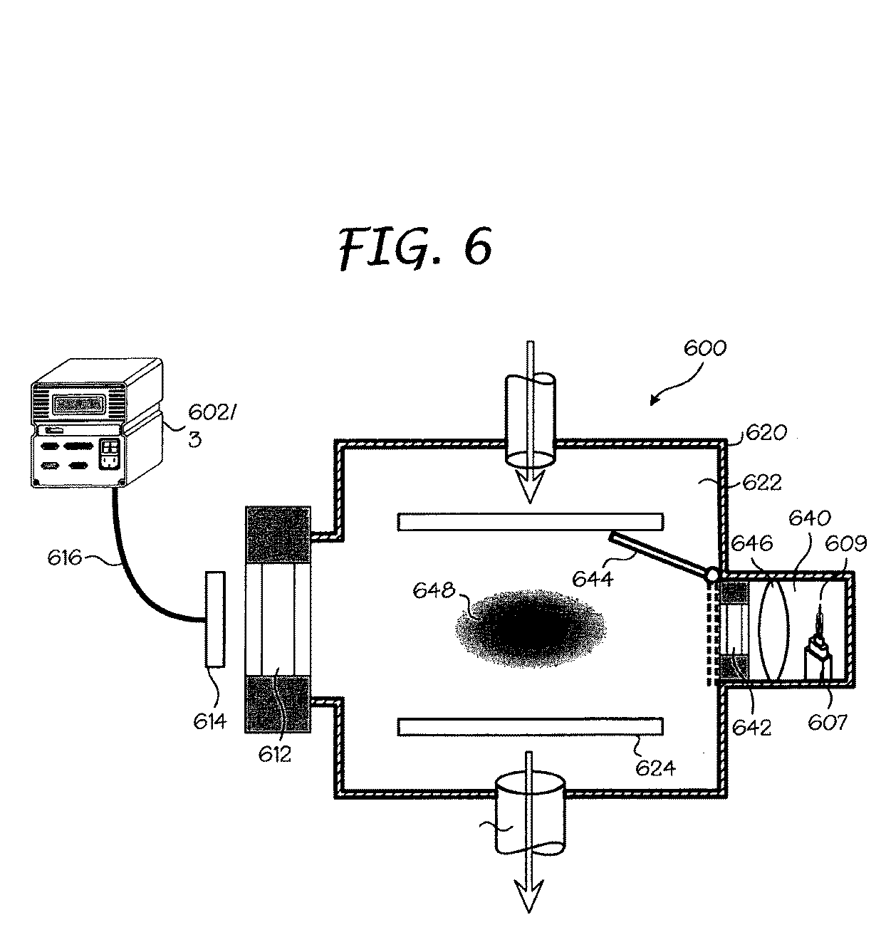
さらに本発明のもう1つの望ましい実施形態によれば、図6に示されるように、光源609は、参照光源チャンバ640内で、ウィンドウ642、移動可能なシャッタ644の背後、及び、チャンバ620の内部622内の所定の位置で、プラズマ光ミミックを製造するための光学要素646の背後に配置される。投影されたプラズマ光ミミック648についての最適な位置が、チャンバ内のプラズマの位置と同じであるか、又は、代わりに、物理的な光源、すなわち、プラズマは、ビューポートウィンドウ612(図5に関して上述されるように)に対して最も見えやすい経路内であるということが期待される。光学要素646は、凹面鏡及び収束レンズの1つであり得る。光学系646を使用して、ウィンドウ642のみを使用するよりも(図5の議論に関してすぐ上で議論されるように)、より多くの光が、チャンバ620を通じ、そして分光器602/03内に移送され得る。好ましくは、内部622内の照明パターンの形状は、プラズマ(図によって提案されるように)によって創り出される光を模倣する。本発明のもう1つの望ましい実施形態によれば、光学系646は、プラズマがビューポートウィンドウ612に対して最も見えやすい経路内で、物理的な光源を配置するための位置で、光源609の実際のイメージを創り出し得る。いずれの場合も、イメージング及び非イメージング光学系の両方は、ここで記述されるように修正され得る。
Further in accordance with another preferred embodiment of the present invention, as shown in FIG. 6, the
図11は、本発明の望ましい実施形態にしたがって、プロセスチャンバに接続される間に、製造分光器及びその光学接続システム上の微調整キャリブレーションステージを実行するためのプロセスを示すフローチャートである。プロセスは、図4を参照して記述されるが、図4−6に示されるどのシステム構成も、微調整キャリブレーションステージとともに等しく良く機能するであろう。微調整キャリブレーションステージは、製造分光器402/403、光ファイバ416及び光学カプラ414をチャンバ420のビューポートウィンドウ412に光学的に接続することによって開始する(ステップ1102)。次に、既知の強度を伴う狭帯域光源409が、所定の位置で、チャンバ420の内部422に配置される(ステップ1104)。狭帯域光源409からの光は、その後、製造分光器402/403によって受けられ(ステップ1106)、そしてそれは出力をつくり出す(ステップ1108)。製造分光器402/403の応答が、参照分光器の出力に対して前に検査されたということを思い出すべきであり、そしてそれ故、その出力が少なくとも部分的に検査される。さらに、製造分光器402/403は、プロセスチャンバ420(ビューポートウィンドウ412を含む)の光学スループットに対して検査されていない。いかに良く製造分光器402/403が検査されるかは、その出力を、狭帯域光源409についての既知のスペクトル強度と比較することによって明らかとなるであろう(ステップ1110)。もし、比較が好ましい場合、これ以上のキャリブレーションは必要でなく、プロセスは終了する。もし、他方で、微調整キャリブレーションが必要であるということをその比較が示した場合、その後、狭帯域光源409に関係するスペクトルのために製造分光器402/403によってつくり出される出力は、狭帯域光源409の既知のスペクトル強度にセットされる(ステップ1112)。これは、製造分光器402/403の全体のスペクトル範囲にわたる強度に対する波長独立調整を行うことによって達成され得る。
FIG. 11 is a flowchart illustrating a process for performing a fine calibration stage on a production spectrometer and its optical connection system while connected to a process chamber, in accordance with a preferred embodiment of the present invention. The process is described with reference to FIG. 4, but any system configuration shown in FIGS. 4-6 will work equally well with the fine calibration stage. The fine calibration stage begins by optically connecting the production spectrograph 402/403, the
本発明のもう1つの望ましい実施形態によれば、参照分光器及びその光学接続システムは、プロセスチャンバで共に検査され得る。この技術が製造施設で全体的に達成されるということが期待される。図12は、本発明の望ましい実施形態にしたがって、参照分光器の応答を検査すること、光学接続システムのスループット、及びプロセスチャンバについての方法を示すフローチャートである。最初に、参照分光器は、その光学接続システムにしたがって、図4−6に関して記述されるように、製造チャンバに接続される(ステップ1202)。次に、局所的な一次標準が、図4に示されるように、製造チャンバ内で配列される(ステップ1204)。局所的な一次標準は、図4に示されるように、プラズマチャンバの容積内で配置され、図5に示されるように、参照分光器ビューの受け角に対して、ビューの領域内で、光チャンバ内に配置され、又は、図6に示されるように、光チャンバから実際のイメージとして投影される。参照分光器は、その後、図8において示されるフローチャートによって例示される方法に関して上述のように、局所的な一次標準に対して検査される。すなわち、光が光源によって投影され、かつ、出力をつくり出す参照分光器で受けられる。出力は、その後、局所的な一次標準についての既知のスペクトル強度と比較され、そして、出力補正係数の組が、生の強度出力を局所的な一次標準についての既知のスペクトル強度に変換する参照分光器について引き出される。結果として、参照分光器及び分光器に対するチャンバからのスループットは、局所的な一次標準キャリブレーション光源に対して全て検査される。 According to another preferred embodiment of the present invention, the reference spectrometer and its optical connection system can be tested together in the process chamber. It is expected that this technology will be achieved overall at the manufacturing facility. FIG. 12 is a flow chart illustrating a method for examining the response of a reference spectrometer, the throughput of the optical connection system, and the process chamber in accordance with a preferred embodiment of the present invention. Initially, the reference spectrometer is connected to the manufacturing chamber as described with respect to FIGS. 4-6 according to its optical connection system (step 1202). Next, local primary standards are arranged in the manufacturing chamber as shown in FIG. 4 (step 1204). The local primary standard is placed in the volume of the plasma chamber, as shown in FIG. 4, and the light in the region of the view, relative to the reference spectrometer view angle, as shown in FIG. Located in the chamber or projected as an actual image from the light chamber as shown in FIG. The reference spectrometer is then examined against a local primary standard as described above with respect to the method illustrated by the flowchart shown in FIG. That is, light is projected by a light source and received by a reference spectrometer that produces an output. The output is then compared to the known spectral intensity for the local primary standard, and a set of output correction factors converts the raw intensity output into a known spectral intensity for the local primary standard. Pulled out of the bowl. As a result, the throughput from the chamber for the reference spectrometer and the spectrometer is all tested against the local primary standard calibration light source.
ここで、参照分光器を使用する製造環境において、光学測定の実行を開始することが可能になる。図4に示されるように、プラズマチャンバの容積内で、局所的な一次標準を再配置することによって、図5に示されるように、製造チャンバの容積内に、局所的な一次標準からの光を投影するために光チャンバのシャッタを開くことによって、又は、図6に示されるように、光チャンバ内の局所的な一次標準キャリブレーション光源から製造チャンバ内の実際のイメージを投影することによって、分光器のインテグリティが、局所的な一次標準キャリブレーション光源とともに定期的に検証され得る。施設内でプロセスチャンバに接続されるそれぞれの及び全ての分光器は、局所的な一次標準に対するキャリブレーションを要求することから、参照分光器の前述の利益が実現されない。 Here, it becomes possible to start the execution of the optical measurement in the manufacturing environment using the reference spectrometer. By relocating the local primary standard within the volume of the plasma chamber as shown in FIG. 4, the light from the local primary standard within the volume of the manufacturing chamber as shown in FIG. By projecting the actual image in the manufacturing chamber from a local primary standard calibration light source in the light chamber, as shown in FIG. The integrity of the spectrometer can be verified periodically with a local primary standard calibration light source. Since each and every spectrometer connected to the process chamber within the facility requires calibration to a local primary standard, the aforementioned benefits of the reference spectrometer are not realized.
それ故、本発明のさらなるもう1つの望ましい実施形態によれば、参照分光器の出力は、プロセスチャンバにも接続される第2の分光器を検査するための第2のキャリブレーションとして利用される。そうすることにおいて、第2の分光器、チャンバ、及び分光器に対するチャンバからのスループットは、そのキャリブレーションについての局所的な一次標準キャリブレーション光源を利用することなく、局所的な一次標準に対してトレース可能である第2の標準に対して全て検査される。 Therefore, according to yet another preferred embodiment of the present invention, the output of the reference spectrometer is utilized as a second calibration for inspecting a second spectrometer that is also connected to the process chamber. . In doing so, the throughput from the chamber to the second spectrometer, chamber, and spectrometer is relative to the local primary standard without utilizing the local primary standard calibration light source for its calibration. All tested against a second standard that is traceable.
今、図12に戻ると、1つのキャリブレーション方法が、局所的な一次標準キャリブレーション光源を製造参照光源に代用することによって実現され、そして、図4−6において示されるように構成され得る(ステップ1208)。製造参照光源の強度は、既知であっても未知であってもよい。次に、検査された出力は、製造参照光源によって放射された光に応答して、参照分光器によってつくり出される(ステップ1210)。製造分光器は、その後、プロセスチャンバに接続され(ステップ1212)(図面に特に示されていない)、そして、検査されていない出力が、製造参照光源によって放射された光に応答して製造分光器によってつくり出される。製造分光器は、その後、製造参照光源に対する参照分光器の応答を使用して、検査され得る(ステップ1214)。 Returning now to FIG. 12, one calibration method is implemented by substituting the local primary standard calibration light source with the manufacturing reference light source and can be configured as shown in FIGS. 4-6 ( Step 1208). The intensity of the production reference light source may be known or unknown. The inspected output is then produced by the reference spectrometer in response to the light emitted by the manufacturing reference light source (step 1210). The production spectrometer is then connected to the process chamber (step 1212) (not specifically shown in the drawing) and the unspected output is responsive to the light emitted by the production reference light source. Created by. The production spectrometer can then be inspected using the reference spectrometer response to the production reference light source (step 1214).
好ましくは、チャンバ及びチャンバウィンドウを介して共通の光学経路を利用するような方法において、参照分光器は製造分光器に同時に接続され、それによって、両方の分光器が、製造参照光源分光器からのキャリブレーション光を同時に受けることが可能になる。そうすることにおいて、製造分光器のキャリブレーションのインテグリティは、製造分光器の出力を参照分光器からの検査された出力を比較することによって、製造参照光源で定期的に検証される。 Preferably, in a method that utilizes a common optical path through the chamber and the chamber window, the reference spectrometer is simultaneously connected to the production spectrometer, so that both spectrometers are from the production reference source spectrometer. It becomes possible to receive calibration light at the same time. In doing so, the calibration integrity of the production spectrometer is periodically verified with the production reference light source by comparing the output of the production spectrometer with the inspected output from the reference spectrometer.
すぐ上で記述される単独の参照分光器を使用するキャリブレーション手順が、施設で各プロセスチャンバについて実行されるということが期待される。オプションとして、初期の参照キャリブレーション(ステップ1204及び1206)は、もし、次のチャンバから得られる検査された出力における変化が、測定されるプロセス変化と比較して小さい場合に、次のチャンバに関して除外され得る。
It is expected that a calibration procedure using a single reference spectrometer described immediately above will be performed for each process chamber at the facility. Optionally, an initial reference calibration (
上述のキャリブレーション技術を使用して、どの製造分光器から検査されたどのスペクトルデータも、もう1つのプロセスチャンバ上の他のどの製造分光器から得られる検査されたスペクトルデータとも比較され得る。さらに、スペクトルデータが、参照分光器を経由して、スペクトル標準仕様に対して検査されるという理由から、チャンバからの光放射スペクトルの前のどの状態も再創造され得る。代わりに、もう1つのチャンバからの光放射スペクトルの状態は、このチャンバにおいて再創造され得る。横断機器及び時間ベースの比較を可能にすることに加え、検査されるどの参照分光器も、分光器を再検査することなく、物理的に再配置され得る(しかしながら、分光器についての参照出力補正係数は、製造分光器から得られる検査されたスペクトルデータを、参照分光器によって得られる検査されたスペクトルデータと比較することによって検証され得る)。 Using the calibration technique described above, any spectral data examined from any production spectrometer can be compared to the examined spectral data obtained from any other production spectrometer on another process chamber. Furthermore, any previous state of the light emission spectrum from the chamber can be recreated because the spectral data is checked against the spectral standard specification via the reference spectrometer. Instead, the state of the light emission spectrum from another chamber can be recreated in this chamber. In addition to enabling cross-instrument and time-based comparisons, any reference spectrometer that is inspected can be physically relocated without re-inspecting the spectrometer (however, reference power correction for the spectrometer) The coefficients can be verified by comparing the examined spectral data obtained from the production spectrometer with the examined spectral data obtained by the reference spectrometer).
以下に記載される望ましい実施形態は、本発明の原理、及び実用化を最も良く説明し、そして、他の当業者が、考えられる特定の使用に適するような様々な改良を伴う様々な実施形態に関する本発明を理解することができるようにするために選択され、記述された。以下に記載される特定の実施形態は、様々な変形及び本発明の範囲及び目的から逸脱することのない範囲において実行され得るので、本発明の範囲を限定するつもりのものではない。それ故、本発明は、示される実施形態に限定されるものではないが、ここで記載される原理及び特徴と一致する最も広い範囲が認められるべきである。 The preferred embodiments described below best illustrate the principles and practical application of the present invention, and various embodiments with various modifications that would be suitable for the particular use contemplated by others skilled in the art. Have been chosen and described so that the invention may be understood. The specific embodiments described below are not intended to limit the scope of the invention, as they may be practiced in various modifications and without departing from the scope and purpose of the invention. Thus, the present invention is not limited to the embodiments shown, but should be accorded the widest scope consistent with the principles and features described herein.
フローチャート及び図中のブロック図は、本発明の様々な実施形態によって、構造、機能性、システムの実行可能な操作、方法、及びコンピュータプログラム製品を例示する。この点で、フローチャートにおける各ブロック又はブロック図は、特定の論理関数を実行するための1以上の実行可能な指示を含む、モジュール、セグメント、又はコードの部分を表示し得る。いくつかの代替の実行において、ブロックにおいて言及される関数は、図において、順序不同に生じ得るということにも留意すべきである。例えば、連続して示される2つのブロックは、実際、実質的に、同時に実行され、又は、ブロックは、時々、含まれる機能性に依存して逆の順番で実行され得る。ブロック図及び/又はフローチャート図の各ブロックは、特定の関数又は動作を実行する特定の目的のハードウェアベースのシステム、又は特定の目的のハードウェア及びコンピュータ機器の組合せによって実行され得る。 The flowcharts and block diagrams in the figures illustrate the structure, functionality, executable operations of the system, methods, and computer program products according to various embodiments of the present invention. In this regard, each block or block diagram in the flowchart may display a module, segment, or portion of code that includes one or more executable instructions for performing a particular logic function. It should also be noted that in some alternative implementations, the functions mentioned in the blocks can occur out of order in the figure. For example, two blocks shown in succession may actually be executed substantially simultaneously, or the blocks may sometimes be executed in reverse order depending on the functionality involved. Each block of the block diagrams and / or flowchart illustrations may be performed by a specific purpose hardware-based system or a combination of specific purpose hardware and computer equipment that performs a specific function or operation.
ここで使用される用語は、特定の実施形態だけを記述する目的のためのものであり、本発明を限定するためのものではない。ここで使用されるように、単数「a」、「an」及び「the」は、文脈がはっきりと別に示している場合を除き、同様に複数の形式を含むことを意図している。用語「comprises」及び/又は「comprising」は、この詳細な説明で使用されるとき、述べられた特徴、整数、ステップ、操作、要素及び/又は成分の存在を特定するが、1以上の他の特徴、整数、ステップ、操作、要素、成分及び/又はそこでのグループを除外するものではない。 The terminology used herein is for the purpose of describing particular embodiments only and is not intended to be limiting of the invention. As used herein, the singular forms “a”, “an”, and “the” are intended to include the plural forms as well, unless the context clearly indicates otherwise. The terms “comprises” and / or “comprising”, as used in this detailed description, identify the presence of the stated feature, integer, step, operation, element, and / or component, but one or more other It does not exclude features, integers, steps, operations, elements, components and / or groups therein.
100…従来技術のキャリブレーションシステム、102…製造分光器、103…検出器、104…製造光源、 200…分光器キャリブレーションシステム、201…分光器キャリブレーションモジュール、202…製造分光器、203…光検出器、204…製造参照光源、205…検査された分光器出力、206…局所的な一次標準キャリブレーション光源、207…検査されていない分光器出力、208…統合球、210…参照分光器、213…光検出器、300…分光器キャリブレーションシステム、301…分光器キャリブレーションモジュール、302…製造分光器、303…光検出器、304…製造参照光源、305…検査された分光器出力、306…局所的な一次標準キャリブレーション光源、307…検査されていない分光器出力、308…統合球、310…参照分光器、313…光検出器、314…収集光学系、316…伝達光学系(光ファイバ)、400…チャンバキャリブレーションシステム、402…製造分光器、403…光検出器、407…配列ジグ、409…チャンバ参照光源、412…チャンバウィンドウ、414…収集光学系、416…伝達光学系(光ファイバ)、420…プロセスチャンバ、422…プロセスチャンバの内部、424…ウェハサポート、500…チャンバキャリブレーションシステム、502…製造分光器、503…光検出器、507…配列ジグ、509…チャンバ参照光源、512…チャンバウィンドウ、514…収集光学系、516…伝達光学系(光ファイバ)、520…プロセスチャンバ、522…プロセスチャンバの内部、ウェハサポート、参照光源チャンバ、光源チャンバウィンドウ、光源チャンバウィンドウシャッタ、チャンバキャリブレーションシステム、602…製造分光器、603…光検出器、607…配列ジグ、609…チャンバ参照光源、612…チャンバウィンドウ、614…収集光学系、616…伝達光学系(光ファイバ)、620…プロセスチャンバ、622…プロセスチャンバの内部、624…ウェハサポート、640…参照光源チャンバ、642…光源チャンバウィンドウ、644…光源チャンバウィンドウシャッタ、646…光源チャンバウィンドウレンズ(鏡)、648…プラズマ光ミミック、
DESCRIPTION OF
Claims (62)
外部表面及び内部表面を有するビューポートウィンドウであって、プロセスチャンバの壁部の1つに沿って配置されるビューポートウィンドウと、を備え、
参照光源は、ビューポートウィンドウで目に見えるようにされ、参照光源からの光を受けるための第2の分光器の光学ポートが、参照光源からの光を受けるためにビューポートウィンドウに光学的に接続される請求項37に記載のキャリブレーションのためのシステム。 A process chamber comprising a plurality of walls at least partially surrounding the process volume ;
A viewport window having an outer surface and an inner surface, the viewport window being disposed along one of the walls of the process chamber ,
The reference light source is made visible in the viewport window, and the optical port of the second spectrometer for receiving light from the reference light source is optically connected to the viewport window for receiving light from the reference light source. 38. A system for calibration according to claim 37, connected .
Applications Claiming Priority (5)
| Application Number | Priority Date | Filing Date | Title |
|---|---|---|---|
| US92837707P | 2007-05-07 | 2007-05-07 | |
| US60/928,377 | 2007-05-07 | ||
| US4558508P | 2008-04-16 | 2008-04-16 | |
| PCT/US2008/005852 WO2008137169A2 (en) | 2007-05-07 | 2008-05-06 | Calibration of a radiometric optical monitoring system used for fault detection and process monitoring |
| US61/045,585 | 2009-07-15 |
Publications (3)
| Publication Number | Publication Date |
|---|---|
| JP2010526998A JP2010526998A (en) | 2010-08-05 |
| JP2010526998A5 JP2010526998A5 (en) | 2011-09-01 |
| JP5555621B2 true JP5555621B2 (en) | 2014-07-23 |
Family
ID=39944179
Family Applications (1)
| Application Number | Title | Priority Date | Filing Date |
|---|---|---|---|
| JP2010507442A Active JP5555621B2 (en) | 2007-05-07 | 2008-05-06 | Calibration of a radiometric optical monitoring system used for fault detection and process monitoring |
Country Status (6)
| Country | Link |
|---|---|
| US (1) | US8125633B2 (en) |
| JP (1) | JP5555621B2 (en) |
| KR (1) | KR101279911B1 (en) |
| CN (1) | CN101689222B (en) |
| TW (1) | TWI379074B (en) |
| WO (1) | WO2008137169A2 (en) |
Families Citing this family (48)
| Publication number | Priority date | Publication date | Assignee | Title |
|---|---|---|---|---|
| KR100984716B1 (en) * | 2010-04-05 | 2010-10-01 | 엘지이노텍 주식회사 | Calibration method of led chip measurement and apparatus therefor |
| CN101982795B (en) * | 2010-09-29 | 2012-12-12 | 中国科学院国家天文台 | Method and system for detecting accuracy of gamma ray spectrometer |
| PE20141402A1 (en) * | 2011-01-26 | 2014-10-29 | Tech Resources Pty Ltd | AN EMISSION SPECTROMETER AND METHOD OF OPERATION |
| US9772226B2 (en) * | 2011-07-11 | 2017-09-26 | Verity Instruments, Inc. | Referenced and stabilized optical measurement system |
| EP2783193A4 (en) | 2011-11-03 | 2015-08-26 | Verifood Ltd | LOW COST SPECTROMETRY SYSTEM FOR FINAL USER FOOD ANALYSIS |
| US10088413B2 (en) | 2011-11-21 | 2018-10-02 | Kla-Tencor Corporation | Spectral matching based calibration |
| WO2013082512A1 (en) * | 2011-11-30 | 2013-06-06 | Labsphere, Inc. | Apparatus and method for mobile device camera testing |
| EP4006542B1 (en) | 2013-08-02 | 2025-10-01 | Verifood Ltd. | Spectrometer comprising sample illuminator |
| EP3090239A4 (en) | 2014-01-03 | 2018-01-10 | Verifood Ltd. | Spectrometry systems, methods, and applications |
| WO2016063284A2 (en) | 2014-10-23 | 2016-04-28 | Verifood, Ltd. | Accessories for handheld spectrometer |
| DE102014117595A1 (en) * | 2014-12-01 | 2016-06-02 | Instrument Systems Optische Messtechnik Gmbh | Method for calibrating a spectroradiometer |
| WO2016105373A1 (en) * | 2014-12-23 | 2016-06-30 | Halliburton Energy Services, Inc. | Methods to correct the spectrum distortion of ffpi sensors induced by dynamic wavelength dependent attenuation |
| WO2016125164A2 (en) | 2015-02-05 | 2016-08-11 | Verifood, Ltd. | Spectrometry system applications |
| WO2016125165A2 (en) | 2015-02-05 | 2016-08-11 | Verifood, Ltd. | Spectrometry system with visible aiming beam |
| WO2016162865A1 (en) | 2015-04-07 | 2016-10-13 | Verifood, Ltd. | Detector for spectrometry system |
| JP6613063B2 (en) * | 2015-07-07 | 2019-11-27 | 大塚電子株式会社 | Optical property measurement system |
| US10066990B2 (en) | 2015-07-09 | 2018-09-04 | Verifood, Ltd. | Spatially variable filter systems and methods |
| US10203246B2 (en) | 2015-11-20 | 2019-02-12 | Verifood, Ltd. | Systems and methods for calibration of a handheld spectrometer |
| US10401823B2 (en) | 2016-02-04 | 2019-09-03 | Makino Inc. | Real time machining process monitoring utilizing preprocess simulation |
| US10254215B2 (en) | 2016-04-07 | 2019-04-09 | Verifood, Ltd. | Spectrometry system applications |
| KR102543349B1 (en) * | 2016-07-11 | 2023-06-30 | 삼성전자주식회사 | Plasma monitoring apparatus |
| EP3488204A4 (en) | 2016-07-20 | 2020-07-22 | Verifood Ltd. | Accessories for handheld spectrometer |
| US10791933B2 (en) | 2016-07-27 | 2020-10-06 | Verifood, Ltd. | Spectrometry systems, methods, and applications |
| CN106197260B (en) * | 2016-09-06 | 2019-02-05 | 京东方科技集团股份有限公司 | Fabry-Perot cavity and its manufacturing method, interferometer and optical wavelength measurement method |
| US10365212B2 (en) * | 2016-11-14 | 2019-07-30 | Verity Instruments, Inc. | System and method for calibration of optical signals in semiconductor process systems |
| EP3330684B1 (en) * | 2016-12-05 | 2019-08-14 | Sick Ag | Method for securing a modulation range |
| US10302488B2 (en) * | 2017-05-24 | 2019-05-28 | Ocean Optics, Inc. | Optical slit for a spectrometer that incorporates a wavelength calibration light source |
| DE102017115660A1 (en) * | 2017-07-12 | 2019-01-17 | Endress+Hauser Conducta Gmbh+Co. Kg | Optical system |
| US10763144B2 (en) * | 2018-03-01 | 2020-09-01 | Verity Instruments, Inc. | Adaptable-modular optical sensor based process control system, and method of operation thereof |
| KR102030428B1 (en) | 2018-03-28 | 2019-11-18 | 삼성전자주식회사 | Calibrator of an optical emission spedctroscopy |
| US10466037B1 (en) * | 2018-05-04 | 2019-11-05 | Ford Motor Company | System and method for controlling gear mounting distance using optical sensors |
| KR102663185B1 (en) * | 2018-08-07 | 2024-05-03 | 삼성전자주식회사 | Optical emission spectroscopy system and method of calibrating the same, and method of fabricating semiconductor device |
| DE102018120006A1 (en) * | 2018-08-16 | 2020-02-20 | Instrument Systems Optische Messtechnik Gmbh | Method and device for monitoring a spectroradiometer |
| US10436643B1 (en) * | 2018-09-28 | 2019-10-08 | Shimadzu Corporation | Spectrometer and retainer used in same |
| CN113167648A (en) | 2018-10-08 | 2021-07-23 | 威利食品有限公司 | Accessory for spectrometer |
| KR102687949B1 (en) | 2018-12-27 | 2024-07-25 | 삼성전자주식회사 | Apparatus and Module treating substrate and Method for manufacturing the semiconductor device |
| US10871396B2 (en) | 2019-04-05 | 2020-12-22 | Samsung Electronics Co., Ltd. | Optical emission spectroscopy calibration device and system including the same |
| US11114286B2 (en) * | 2019-04-08 | 2021-09-07 | Applied Materials, Inc. | In-situ optical chamber surface and process sensor |
| CN110319927B (en) * | 2019-06-27 | 2021-10-08 | 歌尔股份有限公司 | Calibration device |
| KR102772446B1 (en) * | 2019-09-03 | 2025-02-26 | 삼성전자주식회사 | System for optical emission spectrometer and method for calibration of optical emission spectrometer |
| CN110715729B (en) * | 2019-10-31 | 2025-07-25 | 厦门稀土材料研究所 | Light source intensity standard lamp and application thereof |
| CN113130280B (en) * | 2019-12-31 | 2024-03-12 | 中微半导体设备(上海)股份有限公司 | Light intensity monitoring and adjusting mechanism, adjusting method and plasma processing device |
| US11885671B2 (en) * | 2020-06-03 | 2024-01-30 | Labsphere, Inc. | Field spectral radiometers including calibration assemblies |
| JP7445532B2 (en) * | 2020-06-15 | 2024-03-07 | 東京エレクトロン株式会社 | Execution device and execution method |
| US12142494B2 (en) * | 2021-06-07 | 2024-11-12 | Taiwan Semiconductor Manufacturing Company, Ltd. | Small gas flow monitoring of dry etcher by OES signal |
| CN114216882A (en) * | 2021-10-21 | 2022-03-22 | 杭州通尚光电有限公司 | Material transmittance measuring method and material transmittance measuring device |
| US20240019305A1 (en) * | 2022-07-15 | 2024-01-18 | Verity Instruments, Inc. | System and method for fault detection and operational readiness for optical instruments for semiconductor processes |
| CN118857455B (en) * | 2024-07-24 | 2025-09-09 | 广州万孚生物技术股份有限公司 | Photomultiplier calibration method, photomultiplier calibration device, photomultiplier calibration computer device and photomultiplier storage medium |
Family Cites Families (27)
| Publication number | Priority date | Publication date | Assignee | Title |
|---|---|---|---|---|
| GB2132366B (en) | 1982-12-27 | 1987-04-08 | Brunswick Corp | Method and device for testing the permeability of membrane filters |
| JPS6197554A (en) * | 1984-10-19 | 1986-05-16 | Hitachi Ltd | Plasma monitoring method |
| US4866644A (en) * | 1986-08-29 | 1989-09-12 | Shenk John S | Optical instrument calibration system |
| US5459677A (en) * | 1990-10-09 | 1995-10-17 | Board Of Regents Of The University Of Washington | Calibration transfer for analytical instruments |
| US5243546A (en) * | 1991-01-10 | 1993-09-07 | Ashland Oil, Inc. | Spectroscopic instrument calibration |
| EP0533333A3 (en) * | 1991-09-19 | 1993-07-28 | Texaco Development Corporation | Optical photometry system |
| JPH08106992A (en) * | 1994-03-24 | 1996-04-23 | Hitachi Ltd | Plasma processing method and apparatus |
| FR2734360B1 (en) * | 1995-05-19 | 1997-07-04 | Elf Antar France | METHOD OF CORRECTING A SIGNAL DELIVERED BY A MEASURING INSTRUMENT |
| FR2739928B1 (en) * | 1995-10-16 | 1997-11-21 | Elf Antar France | METHOD FOR MONITORING AND MONITORING THE OPERATION OF AN ANALYZER AND A MANUFACTURING UNIT TO WHICH IT IS CONNECTED |
| US6459425B1 (en) * | 1997-08-25 | 2002-10-01 | Richard A. Holub | System for automatic color calibration |
| US5835230A (en) | 1997-07-10 | 1998-11-10 | American Air Liquide Inc. | Method for calibration of a spectroscopic sensor |
| JPH1194735A (en) * | 1997-09-22 | 1999-04-09 | Horiba Ltd | Quantitative analyzer for sample characteristic using spectrophotometry and multivariate analysis and analysis method using it |
| US6134005A (en) | 1998-04-23 | 2000-10-17 | Sandia Corporation | Method and apparatus for monitoring plasma processing operations |
| US6077386A (en) | 1998-04-23 | 2000-06-20 | Sandia Corporation | Method and apparatus for monitoring plasma processing operations |
| KR20040053203A (en) * | 1998-04-23 | 2004-06-23 | 샌디아 코포레이션 | Method and apparatus for monitoring plasma processing operations |
| US6246473B1 (en) | 1998-04-23 | 2001-06-12 | Sandia Corporation | Method and apparatus for monitoring plasma processing operations |
| US6043894A (en) * | 1998-07-10 | 2000-03-28 | Gretamacbeth Llc | Method for maintaining uniformity among color measuring instruments |
| JP2001196353A (en) * | 2000-01-07 | 2001-07-19 | Hamamatsu Photonics Kk | View port, view port with light source, transmission- condition-measuring device for view glass window, plasma monitor device and method for plasma treatment |
| US6621574B1 (en) | 2000-05-25 | 2003-09-16 | Inphotonics, Inc. | Dual function safety and calibration accessory for raman and other spectroscopic sampling |
| EP1372483A2 (en) * | 2001-03-01 | 2004-01-02 | Trustees of Dartmouth College | Fluorescence lifetime spectrometer (fls) and methods of detecting diseased tissues |
| US7048837B2 (en) | 2002-09-13 | 2006-05-23 | Applied Materials, Inc. | End point detection for sputtering and resputtering |
| JP2004177147A (en) * | 2002-11-25 | 2004-06-24 | Shimadzu Corp | Luminescence measuring device |
| US20040214581A1 (en) | 2003-04-23 | 2004-10-28 | Davis Gregory G. | Selecting an operation mode for a device connected to a network |
| US20050020073A1 (en) * | 2003-07-22 | 2005-01-27 | Lam Research Corporation | Method and system for electronic spatial filtering of spectral reflectometer optical signals |
| US7169625B2 (en) | 2003-07-25 | 2007-01-30 | Applied Materials, Inc. | Method for automatic determination of semiconductor plasma chamber matching and source of fault by comprehensive plasma monitoring |
| JP2006202528A (en) | 2005-01-18 | 2006-08-03 | Hitachi Displays Ltd | Image display device |
| JP4710393B2 (en) * | 2005-04-19 | 2011-06-29 | 株式会社島津製作所 | Excitation spectrum correction method in fluorescence spectrophotometer |
-
2008
- 2008-05-06 JP JP2010507442A patent/JP5555621B2/en active Active
- 2008-05-06 US US12/151,449 patent/US8125633B2/en active Active
- 2008-05-06 CN CN2008800153086A patent/CN101689222B/en active Active
- 2008-05-06 KR KR1020097025537A patent/KR101279911B1/en active Active
- 2008-05-06 TW TW097116708A patent/TWI379074B/en active
- 2008-05-06 WO PCT/US2008/005852 patent/WO2008137169A2/en not_active Ceased
Also Published As
| Publication number | Publication date |
|---|---|
| KR20100017693A (en) | 2010-02-16 |
| JP2010526998A (en) | 2010-08-05 |
| US20090103081A1 (en) | 2009-04-23 |
| WO2008137169A2 (en) | 2008-11-13 |
| CN101689222A (en) | 2010-03-31 |
| CN101689222B (en) | 2012-12-26 |
| TW200905175A (en) | 2009-02-01 |
| US8125633B2 (en) | 2012-02-28 |
| WO2008137169A3 (en) | 2010-01-07 |
| KR101279911B1 (en) | 2013-06-28 |
| TWI379074B (en) | 2012-12-11 |
Similar Documents
| Publication | Publication Date | Title |
|---|---|---|
| JP5555621B2 (en) | Calibration of a radiometric optical monitoring system used for fault detection and process monitoring | |
| KR102489184B1 (en) | System and method for calibration of optical signals in semiconductor process systems | |
| US8358416B2 (en) | Methods and apparatus for normalizing optical emission spectra | |
| JP2010526998A5 (en) | ||
| US10151633B2 (en) | High accuracy absorbance spectrophotometers | |
| CN113945553B (en) | System and method for improving calibration transfer between multiple Raman analyzer devices | |
| US9772226B2 (en) | Referenced and stabilized optical measurement system | |
| US20200319025A1 (en) | Optical emission spectroscopy calibration device and system including the same | |
| US7420736B2 (en) | Method for determining optimum grating parameters for producing a diffraction grating for a VUV spectrometer | |
| KR102703004B1 (en) | Process monitoring system for plasma apparatus | |
| TWI880367B (en) | Process monitoring system for plasma device | |
| KR102017559B1 (en) | A Process Monitoring Equipment Having Calibration Lamp And Method Of Process Monitoring Method Using The Same | |
| TW202538246A (en) | Integrated module type spectroscopic system and method for diagnosing process using the same |
Legal Events
| Date | Code | Title | Description |
|---|---|---|---|
| A521 | Request for written amendment filed |
Free format text: JAPANESE INTERMEDIATE CODE: A523 Effective date: 20110506 |
|
| A621 | Written request for application examination |
Free format text: JAPANESE INTERMEDIATE CODE: A621 Effective date: 20110506 |
|
| A521 | Request for written amendment filed |
Free format text: JAPANESE INTERMEDIATE CODE: A523 Effective date: 20110713 |
|
| A977 | Report on retrieval |
Free format text: JAPANESE INTERMEDIATE CODE: A971007 Effective date: 20130422 |
|
| A131 | Notification of reasons for refusal |
Free format text: JAPANESE INTERMEDIATE CODE: A131 Effective date: 20130607 |
|
| RD04 | Notification of resignation of power of attorney |
Free format text: JAPANESE INTERMEDIATE CODE: A7424 Effective date: 20130726 |
|
| A601 | Written request for extension of time |
Free format text: JAPANESE INTERMEDIATE CODE: A601 Effective date: 20130902 |
|
| A602 | Written permission of extension of time |
Free format text: JAPANESE INTERMEDIATE CODE: A602 Effective date: 20130909 |
|
| A601 | Written request for extension of time |
Free format text: JAPANESE INTERMEDIATE CODE: A601 Effective date: 20131002 |
|
| A602 | Written permission of extension of time |
Free format text: JAPANESE INTERMEDIATE CODE: A602 Effective date: 20131009 |
|
| A601 | Written request for extension of time |
Free format text: JAPANESE INTERMEDIATE CODE: A601 Effective date: 20131105 |
|
| A602 | Written permission of extension of time |
Free format text: JAPANESE INTERMEDIATE CODE: A602 Effective date: 20131112 |
|
| A521 | Request for written amendment filed |
Free format text: JAPANESE INTERMEDIATE CODE: A523 Effective date: 20131206 |
|
| TRDD | Decision of grant or rejection written | ||
| A01 | Written decision to grant a patent or to grant a registration (utility model) |
Free format text: JAPANESE INTERMEDIATE CODE: A01 Effective date: 20140502 |
|
| A61 | First payment of annual fees (during grant procedure) |
Free format text: JAPANESE INTERMEDIATE CODE: A61 Effective date: 20140602 |
|
| R150 | Certificate of patent or registration of utility model |
Ref document number: 5555621 Country of ref document: JP Free format text: JAPANESE INTERMEDIATE CODE: R150 |
|
| RD02 | Notification of acceptance of power of attorney |
Free format text: JAPANESE INTERMEDIATE CODE: R3D02 |
|
| R250 | Receipt of annual fees |
Free format text: JAPANESE INTERMEDIATE CODE: R250 |
|
| R250 | Receipt of annual fees |
Free format text: JAPANESE INTERMEDIATE CODE: R250 |
|
| R250 | Receipt of annual fees |
Free format text: JAPANESE INTERMEDIATE CODE: R250 |
|
| R250 | Receipt of annual fees |
Free format text: JAPANESE INTERMEDIATE CODE: R250 |
|
| R250 | Receipt of annual fees |
Free format text: JAPANESE INTERMEDIATE CODE: R250 |
|
| R250 | Receipt of annual fees |
Free format text: JAPANESE INTERMEDIATE CODE: R250 |
|
| R250 | Receipt of annual fees |
Free format text: JAPANESE INTERMEDIATE CODE: R250 |
|
| R250 | Receipt of annual fees |
Free format text: JAPANESE INTERMEDIATE CODE: R250 |
|
| R250 | Receipt of annual fees |
Free format text: JAPANESE INTERMEDIATE CODE: R250 |