JP5540538B2 - Fan filter unit - Google Patents
Fan filter unit Download PDFInfo
- Publication number
- JP5540538B2 JP5540538B2 JP2009073325A JP2009073325A JP5540538B2 JP 5540538 B2 JP5540538 B2 JP 5540538B2 JP 2009073325 A JP2009073325 A JP 2009073325A JP 2009073325 A JP2009073325 A JP 2009073325A JP 5540538 B2 JP5540538 B2 JP 5540538B2
- Authority
- JP
- Japan
- Prior art keywords
- suction
- auxiliary duct
- fan
- filter unit
- suction auxiliary
- Prior art date
- Legal status (The legal status is an assumption and is not a legal conclusion. Google has not performed a legal analysis and makes no representation as to the accuracy of the status listed.)
- Active
Links
Images


Landscapes
- Filtering Of Dispersed Particles In Gases (AREA)
- Ventilation (AREA)
Description
本発明は、半導体、液晶、およびプラズマディスプレイパネルなどの、清浄空間を必要とする製造装置で使用されるファンフィルターユニットに関する。 The present invention relates to a fan filter unit used in a manufacturing apparatus that requires a clean space, such as a semiconductor, a liquid crystal, and a plasma display panel.
従来、この種のファンフィルターユニットにおいて、吸込口は吸込板形状の最適化により、ファンの最大効率を引き上げているが、吸込気流の乱れ改善に特別な手段を用いてはいない。(例えば特許文献1参照)。 Conventionally, in this type of fan filter unit, the suction port has raised the maximum efficiency of the fan by optimizing the shape of the suction plate, but no special means is used to improve the turbulence of the suction airflow. (For example, refer to Patent Document 1).
従来のファンフィルターユニットでは、ファン効率の最大化を追求して吸込口形状を決定しているが、吸込気流の乱れ改善について考慮されていないため、ファンに吸込まれる気流が乱れていることによって生じるファン効率のロスや、吸込気流により生じた小さな複数の渦が衝突し吸込み側で発生する騒音、またファンと吸込板の隙間を逆流することにより笛音を発生させている。 In the conventional fan filter unit, the shape of the suction port is determined in pursuit of maximization of the fan efficiency, but since the improvement of the turbulence of the suction airflow is not considered, the airflow sucked into the fan is disturbed. Loss of fan efficiency generated, noise generated on the suction side due to collision of a plurality of small vortices generated by the suction airflow, and whistle sound are generated by backflowing the gap between the fan and the suction plate.
本発明のファンフィルターユニットは上記目的を達成するために、箱型状のチャンバー内の上部に前記チャンバーに固定された吸込板の吸込口を有し、ターボファンとモーターからなるファンユニットを、前記チャンバー内部に有し、このファンユニットの吹出側にファイルターを設け、前記吸込板の上部に吸込み側に突出した吸込補助ダクトを設け、気流が前記吸込補助ダクトに流入してから前記吸込口まで流れる距離は、前記吸込補助ダクトの下流端と前記ターボファンとの距離より長いことを特徴としたものである。 In order to achieve the above object, the fan filter unit of the present invention has a suction port of a suction plate fixed to the chamber in the upper part of a box-shaped chamber , and a fan unit composed of a turbo fan and a motor, The inside of the chamber has a filter on the blowout side of the fan unit, and a suction auxiliary duct that protrudes toward the suction side is provided on the upper part of the suction plate. After the airflow flows into the suction auxiliary duct to the suction port The flowing distance is longer than the distance between the downstream end of the suction auxiliary duct and the turbofan .
本発明のファンフィルターユニットは上記目的を達成するために、箱型状のチャンバー上部に吸込口を有し、ターボファンとモーターからなるファンユニットを、前記チャンバー内部に有し、このファンユニットの吹出側にファイルターを設け、前記吸込口よりも上
流側に、前記ファンの回転軸方向に前記チャンバーの前記吸込口から突出した吸込補助ダクトを備えたものである。
In order to achieve the above object, the fan filter unit of the present invention has a suction port at the top of a box-shaped chamber, and a fan unit comprising a turbo fan and a motor inside the chamber. Provide a filter on the side above the suction port
A suction auxiliary duct protruding from the suction port of the chamber in the rotation axis direction of the fan is provided on the flow side .
また他の手段は、吸込補助ダクトが正多角筒状であり、その正多角形の内接円の中心が前記ファンの回転軸上にあることを特徴としたものである。 Another means is that the suction auxiliary duct is a regular polygonal cylinder, and the center of the inscribed circle of the regular polygon is on the rotation axis of the fan.
また他の手段は、吸込補助ダクトが円筒状であり、前記ファンと同心軸であることを特徴としたものである。 The other means is characterized in that the suction auxiliary duct is cylindrical and is concentric with the fan.
また他の手段は、チャンバー上面と同一の平面と、吸込補助ダクトの側面と同一の平面が、チャンバー上面側から見て鋭角となるように交差するように、吸込補助ダクトに傾斜を備えたことを特徴としたものである。 Another means is that the suction auxiliary duct is provided with an inclination so that the same plane as the upper surface of the chamber and the same plane as the side surface of the auxiliary suction duct intersect at an acute angle when viewed from the upper side of the chamber. It is characterized by.
また他の手段は、吸込補助ダクトの開口面積が、上流側ほど大きくなり、吸込補助ダクトの垂直断面形状は、一定の曲率を有していることを特徴としたものである。 Another means is characterized in that the opening area of the suction auxiliary duct becomes larger toward the upstream side, and the vertical sectional shape of the suction auxiliary duct has a certain curvature.
また他の手段は、吸込補助ダクト側面の内側にチャンバー上部の吸込口の開口中心へ伸びる錐体型の送風ガイドを備えたことを特徴としたものである。 Another means is characterized in that a cone-shaped air blowing guide is provided on the inner side of the suction auxiliary duct side surface and extends to the center of the opening of the suction port at the upper part of the chamber.
また他の手段は、吸込補助ダクト内部をファン回転軸と平行に分割する仕切り板を備えたことを特徴としたものである。 Another means includes a partition plate that divides the inside of the suction auxiliary duct in parallel with the fan rotation axis.
また他の手段は、前記仕切り板を平行に複数枚設けたことを特徴としたものである。 Another means is characterized in that a plurality of the partition plates are provided in parallel.
また他の手段は、前記仕切り板を格子状に複数枚設けたことを特徴としたものである。 Another means is characterized in that a plurality of the partition plates are provided in a lattice shape.
また他の手段は、吸込補助ダクト内の仕切り板の上流側端面エッジ部にR形状を備えたことを特徴としたものである。 Another means is characterized in that the upstream end surface edge portion of the partition plate in the suction auxiliary duct has an R shape.
また他の手段は、吸込補助ダクトに全体を覆う天面部を設け、その天面部に複数の孔を並べて配置することを特徴としたものである。 Another means is characterized in that a top surface portion covering the entire suction auxiliary duct is provided, and a plurality of holes are arranged side by side on the top surface portion.
また他の手段は、前記吸込補助ダクトに設けた前記天面部の複数の孔の上部端面エッジ部に、R形状を備えたことを特徴としたものである。 In another aspect, the upper end surface edge portion of the plurality of holes in the top surface portion provided in the suction auxiliary duct is provided with an R shape.
これらの手段により、吸込口の気流の乱れを低減しファン効率を上昇させ、吸込側の気流の衝突などに起因する騒音を低減させたファンフィルターユニットが得られる。 By these means, it is possible to obtain a fan filter unit in which the disturbance of the airflow at the suction port is reduced, the fan efficiency is increased, and the noise caused by the collision of the airflow on the suction side is reduced.
本発明の請求項1記載の発明は、箱型状のチャンバーと、そのチャンバー内の上部に前記チャンバーに固定された吸込板の吸込口を有し、ターボファンとモーターからなるファンユニットを、前記チャンバー内部に有し、このファンユニットの吹出側にフィルターを設けたファンフィルターユニットにおいて、前記吸込口よりも上流側に、前記ターボファンの回転軸方向に前記チャンバーの前記吸込板の上部に吸込み側に突出した吸込補助ダクトを設け、気流が前記吸込補助ダクトに流入してから前記吸込口まで流れる距離は、前記吸込補助ダクトの下流端と前記ターボファンとの距離より長いことを特徴としたものであり、吸込補助ダクトを備えることにより、吸込口において気流が衝突することと共に、それにより生ずる乱れや衝突音を防ぎ、ファン効率をより高めるという作用を有するものである。
The invention of
本発明の請求項1記載の発明は、箱型状のチャンバーと、そのチャンバー上部に吸込口を有し、ターボファンとモーターからなるファンユニットを、前記チャンバー内部に有し、このファンユニットの吹出側にフィルターを設けたファンフィルターユニットにおいて、前記吸込口よりも上流側に、前記ファンの回転軸方向に前記チャンバーの前記吸込口から突出した吸込補助ダクトを備えたものであり、吸込補助ダクトを備えることにより、吸込口において気流が衝突することと共に、それにより生ずる乱れや衝突音を防ぎ、ファン効率をより高めるという作用を有するものである。 According to the first aspect of the present invention, there is provided a box-shaped chamber, a fan unit having a suction port at the upper portion of the chamber, and a turbo fan and a motor inside the chamber. In the fan filter unit provided with a filter on the side, a suction auxiliary duct that protrudes from the suction port of the chamber in the direction of the rotation axis of the fan is provided upstream of the suction port. By providing, the airflow collides at the suction port, and the turbulence and collision sound caused thereby are prevented, and the fan efficiency is further increased.
また、吸込補助ダクトが正多角筒状であり、その正多角形の内接円の中心が前記ファンの回転軸上にあることを特徴としたものである。仮に吸込口中心に対し吸込補助ダクトの設置位置がずれると仮定すると、吸込補助ダクトに部分的に吸込力のバラつきが起こり、吸込気流が多くなる部分と少なくなる部分ができる。これにより吸込み気流の偏りと乱れが発生することとなる。本発明では、ファンの回転軸と正多角形の内接円の中心とを一致させることにより、吸込み気流の偏りと乱れの発生を防ぎ、気流が満遍なく吸込口中心に流れるように風向きを制御することができ、吸込口の乱れをより低減し、それにより生ずる乱れや衝突音を防ぎ、ファン効率を高めるという作用を有するものである。 The suction auxiliary duct is a regular polygonal cylinder, and the center of the inscribed circle of the regular polygon is on the rotation axis of the fan. If it is assumed that the installation position of the suction auxiliary duct is deviated from the center of the suction port, the suction auxiliary duct partially varies in suction force, and a portion where the suction airflow increases and a portion where the suction airflow increases are formed. As a result, the suction air flow is biased and turbulent. In the present invention, by aligning the rotation axis of the fan with the center of the inscribed circle of the regular polygon, it prevents the occurrence of bias and turbulence of the suction airflow, and controls the wind direction so that the airflow flows uniformly to the center of the suction port. It is possible to reduce the disturbance of the suction port, prevent the disturbance and the collision noise caused thereby, and increase the fan efficiency.
また、吸込補助ダクトが円筒状であり、前記ファンと同心軸であることを特徴としたものであり、円筒状にすることにより吸込補助ダクトの吸込気流流入部と吸込口との距離が等しくなり、吸込補助ダクトの流入部の全周に等しい吸込力を加えることができる。これにより吸込気流の偏りと乱れの発生をより少なくし、それにより生ずる渦や衝突音を防ぎ、ファン効率を高めるという作用を有するものである。 In addition, the suction auxiliary duct is cylindrical and is concentric with the fan, and by making it cylindrical, the distance between the suction air flow inlet of the suction auxiliary duct and the suction port becomes equal. A suction force equal to the entire circumference of the inflow portion of the suction auxiliary duct can be applied. As a result, the suction airflow is less biased and turbulence is generated, vortices and collision noises are thereby prevented, and fan efficiency is increased.
また、チャンバー上面と同一の平面と、吸込補助ダクトの側面と同一の平面が、チャンバー上面側から見て鋭角となるように交差するように、吸込補助ダクトに傾斜を備えたものであり、吸込気流が傾斜に沿って滑らかに流れていき、気流の衝突や滞留、よどみを低減し整流効果をうながし、吸込気流の乱れや衝突音を防ぎ、ファン効率を高めるという作用を有するものである。 In addition, the suction auxiliary duct is provided with an inclination so that the same plane as the upper surface of the chamber and the same plane as the side surface of the auxiliary suction duct intersect at an acute angle when viewed from the upper side of the chamber. The airflow flows smoothly along the slope, reduces the collision, stagnation, and stagnation of the airflow, promotes the rectification effect, prevents the turbulence of the intake airflow and the collision sound, and increases the fan efficiency.
また、吸込補助ダクトの開口面積が、上流側ほど大きくなり、吸込補助ダクトの垂直断面形状は、一定の曲率を有していることを特徴としたものであり、吸込補助ダクトに気流が沿って流れることにより、より滑らかに気流を吸込むことを促すことができる。また、吸込補助ダクトでの風向きを滑らかに変えることができ、吸込補助ダクト内での吸込気流の乱れや衝突音をさらに防ぎ、ファン効率を高めるという作用を有するものである。 In addition, the opening area of the suction auxiliary duct becomes larger toward the upstream side, and the vertical cross-sectional shape of the suction auxiliary duct has a certain curvature, and the air flow along the suction auxiliary duct By flowing, it can be urged to suck the airflow more smoothly. In addition, the direction of the wind in the suction auxiliary duct can be changed smoothly, so that the disturbance of the suction air flow and the collision sound in the suction auxiliary duct can be further prevented and the fan efficiency can be increased.
また、吸込補助ダクト側面の内側にチャンバー上部の吸込口の開口中心へ伸びる錐体型の送風ガイドを備えたものであり、吸込補助ダクトの径を大きくし、より多くの吸込風量を確保する際に、広い範囲からの吸込であっても、吸込気流の滞留やよどみをなくすことができる。さらに滑らかに気流を吸込口へ促し、吸込補助ダクト内部で気流が衝突することにより生ずる乱れや衝突音を防ぎ、ファン効率を高めるという作用を有する。 In addition, it is equipped with a cone-shaped air guide that extends to the center of the opening of the suction port at the top of the chamber inside the side of the suction auxiliary duct. When increasing the diameter of the suction auxiliary duct and securing a larger amount of suction air Even if it is suction from a wide range, it is possible to eliminate stagnation and stagnation of the suction airflow. Further, the air flow is smoothly urged to the suction port, and the disturbance and the collision sound caused by the collision of the air flow inside the suction auxiliary duct are prevented, and the fan efficiency is increased.
また、吸込補助ダクト内部をファン回転軸と平行に分割する仕切り板を備えたことを特徴としたものであり、特に大きな吸引力を備え吸込補助ダクトへ大量の気流が流入する際に、大きな吸込力によって全方向から吸引される気流が一気に中心部に集まり、中心部で衝突することによって生じる気流の乱れと衝突音を防ぐという作用を有する。 It also features a partition plate that divides the inside of the suction auxiliary duct in parallel with the fan rotation axis, and has a large suction force, especially when a large amount of airflow flows into the suction auxiliary duct. Airflow sucked from all directions by force gathers at the center, and has the effect of preventing turbulence of airflow and collision noise caused by collision at the center.
また、前記仕切り板を平行に複数枚設けたことを特徴とするものであり、吸込補助ダクト内部の仕切り板に沿って気流を流すことにより、気流の整流効果を高めるとともに、吸込補助ダクト内での渦の発生を小さくすることにより、ファン効率を高めるという作用を有する。 In addition, a plurality of the partition plates are provided in parallel, and by flowing an air flow along the partition plate inside the suction auxiliary duct, the air flow rectifying effect is enhanced, and in the suction auxiliary duct By reducing the generation of vortices, the fan efficiency is increased.
また、前記仕切り板を格子状に複数枚設けたことを特徴とするものであり、吸込補助ダクト内を細分化することにより、気流が沿って流れる仕切り板部分をふやすことができ、それにより気流の整流化と渦の発生の抑制を図り、吸込み気流の乱れをより低減し、ファン効率を高めるという作用を有する。 In addition, a plurality of the partition plates are provided in a lattice shape, and by dividing the inside of the suction auxiliary duct, the partition plate portion along which the airflow flows can be softened, whereby the airflow Rectification of the air and suppression of the generation of vortices, the disturbance of the suction airflow is further reduced, and the fan efficiency is increased.
また、前記吸込補助ダクト内の仕切り板の上流側端面エッジ部にR形状を備えたものであり、仕切り板の上流側端面エッジ部を通過する際に、鋭利なエッジがある場合、風切音が発生するとともに、渦も発生する。しかし仕切り板のエッジにR形状の丸みをもたせることによって、気流の仕切り板への衝突を滑らかにすることによって、より吸込気流の乱れを低減し、ファン効率を高めるとともに、吸込騒音を小さくするという作用を有する。 Further, if the upstream end face edge portion of the partition plate in the suction auxiliary duct has an R shape, and there is a sharp edge when passing through the upstream end face edge portion of the partition plate, wind noise And vortices are also generated. However, by making the edge of the partition plate rounded in an R shape, smoothing the collision of the airflow with the partition plate reduces the turbulence of the suction airflow, increases the fan efficiency, and reduces the suction noise. Has an effect.
また、吸込補助ダクトに吸込補助ダクト全体を覆う天面部を設け、その天面部に複数の孔を並べて配置することを特徴としたものであり、吸込補助ダクトに気流が流れ込む前に、複数の孔による整流効果を気流に与え、なだらかに吸込み補助ダクトに気流が流れ込み、さらに吸込補助ダクトを通ることによって整流され、吸込み気流の乱れを低減し、ファン効率を高める作用を有する。 In addition, the top surface portion that covers the entire suction auxiliary duct is provided in the suction auxiliary duct, and a plurality of holes are arranged side by side on the top surface portion, and a plurality of holes are formed before the airflow flows into the suction auxiliary duct. The airflow is gently flown into the suction auxiliary duct and further rectified by passing through the suction auxiliary duct, thereby reducing the disturbance of the suction airflow and increasing the fan efficiency.
また、前記吸込補助ダクトに設けた前記天面部の複数の孔の上部端面エッジ部に、R形状を備えたことを特徴とするものであり、天面の孔の上部端面エッジ部に丸みをもたせることにより、風切音と渦の発生を抑制し、整流効果をさらに高め、より吸込気流の乱れを低減しファン効率を高めるとともに、吸込騒音を小さくするという作用を有する。 Further, the upper end surface edge portion of the plurality of holes in the top surface portion provided in the suction auxiliary duct is provided with an R shape, and the upper end surface edge portion of the hole in the top surface is rounded. This suppresses the generation of wind noise and vortices, further enhances the rectification effect, further reduces the disturbance of the suction airflow, increases the fan efficiency, and reduces the suction noise.
以下、本発明の実施の形態について図面を参照しながら説明する。 Hereinafter, embodiments of the present invention will be described with reference to the drawings.
(実施の形態1)
図1に示すように、第1の実施の形態のファンフィルターユニットは、ターボ型のファン2とモーター3からなるファンユニット4を箱形状のチャンバー5に内蔵している。吸込板8はチャンバー5に固定されており、ファンユニット4はブリッジ形状のサポート7によりチャンバー5に固定されている。ファンユニット4の吹出側となる下方にはフィルター6を設けている。吸込口1の吸込板8の上部には、吸込み側に突出するように吸込補助ダクト9が取り付けられている。
(Embodiment 1)
As shown in FIG. 1, the fan filter unit according to the first embodiment includes a
上記構成において、ファンユニット4を運転することによって、吸込補助ダクト9を気
流が通過し、吸込口1より空気が吸込まれ、チャンバー5内に送り込まれる(矢印で空気の流れを示す)。
In the above configuration, when the
このとき、吸込補助ダクトがなければ、吸込口1には幅広い範囲から気流が流れてくるため、吸込口1では吸込まれた多くの気流が衝突を起こし、乱れた気流がファン2に吸込まれていく。これにより吸込口1での吸込み気流の衝突音が大きくなる。さらに、ファン2に吸込まれるときに吸込み気流は多くの渦を有することとなり、ファン2の抵抗が大きくなり、ファン効率を悪化させる要因となる。また、図13に示すように、吸込板8からファン2までの距離を長くし、その間で吸込み気流の整流化を図る構成とした場合には、チャンバー5そのものの高さが高くなり、ファン2上部にスペースが生まれる。ファン2から吐き出された気流の一部は、チャンバー5側面にあたり、そのスペースに流れ込み、そこで滞留やよどみを引き起こす。このため、ファン2から吐き出された気流は損失することとなり、フィルター6を通過する気流は減少する。
At this time, if there is no suction auxiliary duct, airflow flows from a wide range to the
本実施の形態では、吸込補助ダクト9を取り付けることによって、吸込気流を制限することができ、さらに吸込み気流の風向を鉛直下向きに変えるため、水平方向での気流の衝突が減少する。同時に吸込口1付近での気流の衝突による騒音も減少する。また気流が吸込補助ダクト9に流入してから吸込口1まで流れるのに距離があるため、その分気流は整流されより層流状態に近づき、渦の発生が少ない状態でファン2に吸込まれる。そのため、ファン2の抵抗成分が減少し、ファン効率が上昇するとともに、気流がファン2から流れ出る際の流体騒音も減少させることができるという効果がある。
In this embodiment, the suction airflow can be restricted by attaching the suction
(実施の形態2)
第2の実施の形態のファンフィルターユニットは、図2に示すように、吸込補助ダクト9が正多角筒状であり、その正多角形の内接円の中心が前記ファン2の回転軸上にあるようにチャンバー5に取り付ける。
(Embodiment 2)
In the fan filter unit of the second embodiment, as shown in FIG. 2, the suction
上記構成において、ファン2の回転軸と正多角形の内接円の中心とが一致することにより、吸込補助ダクト9へ吸込まれる気流は満遍なく吸込口1の中心に流れるように風向きを制御することができる。仮に吸込口1中心に対し吸込補助ダクト9の設置位置がずれると仮定すると、吸込補助ダクト9に部分的に吸込力のバラつきが起こり、吸込気流が多くなる部分と少なくなる部分ができる。これにより吸込み気流の偏りと乱れが発生することとなる。上記構成をとることにより、これら吸込み気流の偏りと乱れの発生を防ぐことができる。さらに、これらにより生ずる渦や衝突音を防ぎ、ファン効率を高めることができる。
In the above configuration, the direction of the wind is controlled so that the air flow sucked into the suction
(実施の形態3)
第3の実施の形態のファンフィルターユニットは、図3に示すように、吸込補助ダクト9が円筒状であり、前記ファン2と同心軸であるように取り付ける。
(Embodiment 3)
As shown in FIG. 3, the fan filter unit of the third embodiment is attached so that the suction
上記構成において、吸込補助ダクト9の形状を円筒状にすることにより、吸込補助ダクト9の吸込気流流入部と吸込口1との距離が等しくなり、吸込補助ダクト9の流入部の全周に等しい吸込力を加えることができる。これにより吸込補助ダクト9の流入部の吸込気流の偏りをなくすことができ、渦や衝突音の発生を防ぎ、ファン効率を高めることができる。
In the above configuration, by making the shape of the suction
(実施の形態4)
第4の実施の形態のファンフィルターユニットは、図4に示すように、チャンバー5上面と同一の平面と、吸込補助ダクト9の側面と同一の平面が、チャンバー5上面側から見て鋭角となるように交差するように、吸込補助ダクト9に傾斜を備えた構造を有する。
(Embodiment 4)
In the fan filter unit of the fourth embodiment, as shown in FIG. 4, the same plane as the upper surface of the
上記構成において、吸込補助ダクト9の流入部面積を大きな構造とすることができ、より多くの気流を吸込むことができる。さらに、吸込補助ダクト9の側面に傾斜を備えることで、傾斜に沿って滑らかに気流が吸込まれていくため、気流の衝突や滞留、よどみを低減し整流効果を促すことができる。さらに気流の風向きを変えるための負荷が低減できるとともに、気流の衝突を低減でき、整流効果を促すことができるため、よりファン効率を改善することができる。また吸込補助ダクト9への流入部で生ずる衝突音などを防ぐことができる。
In the said structure, the inflow part area of the suction auxiliary |
(実施の形態5)
第5の実施の形態のファンフィルターユニットは、図5に示すように、吸込補助ダクト9の開口面積が、上流側ほど大きくなり、吸込補助ダクト9の垂直断面形状は、一定の曲率を有している構造を有する。
(Embodiment 5)
In the fan filter unit of the fifth embodiment, as shown in FIG. 5, the opening area of the suction
上記構成において、吸込補助ダクト9を通過する気流は、吸込補助ダクト9の上流側開口部にて幅広い範囲から吸込まれ、吸込口1に向かい壁面を沿って滑らかに送られる。さらに吸込補助ダクト9の垂直断面形状は一定の曲率を有しているため、その滑らかな勾配に沿って吸込み気流が流れることによって、吸込補助ダクト内での気流の風向きを滑らかに吸込口1方向へ変えることができる。また吸込補助ダクト9の持つ一定の曲率形状は、エッジ部がないため、曲率の大小を調節することによって風向きを調整する際に、気流の剥離による渦の発生を抑制できる。これらの効果により、吸込補助ダクト9内での気流の乱れと衝突音などを防ぎ、ファン効率を高めるという作用を有するものである。
In the above configuration, the airflow passing through the suction
(実施の形態6)
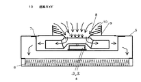
第6の実施の形態のファンフィルターユニットは、図6に示すように吸込補助ダクト9側面の内側にチャンバー5上部の吸込口1の開口中心へ伸びる錐体型の送風ガイド10を備えた構造を持つ。
(Embodiment 6)
As shown in FIG. 6, the fan filter unit according to the sixth embodiment has a structure including a cone-shaped
上記構成において、吸込補助ダクト9の径を大きくしより多くの吸込風量を確保する際に、広い範囲からの吸込であっても錐体型の送風ガイド10により吸込口1に気流を滑らかに流すことによって、吸込気流の滞留やよどみをなくすことができる。また、送風ガイド10に沿って吸込み気流が流れることにより、吸込口1に気流が到達する前での吸込気流の衝突と乱れを防ぐことにより、吸込補助ダクト9内の気流をより整流した状態で吸込口1に気流を流すことができる。このため、吸込補助ダクト9内の衝突音、乱れを防ぎ、ファン効率を高めることができる。
In the above configuration, when the diameter of the suction
(実施の形態7)
第7の実施の形態のファンフィルターユニットは、図7に示すように、吸込補助ダクト9内部をファン2回転軸と平行に分割する仕切り板11を備えた構造を持つ。
(Embodiment 7)
As shown in FIG. 7, the fan filter unit of the seventh embodiment has a structure including a
上記構成において、吸込補助ダクト9へ気流が流入する際に、特に大風量の吸込気流が流れる際には、大きな吸込力によって様々な方向からくる気流が仕切り板11に衝突し、そのまま仕切り板11に沿って整流されて吸込口1に流れていく。仕切り板11がない場合は、吸込気流が一気に吸込口1上部に集まり、そこで衝突することによって気流の乱れと衝突音が生じる。従って仕切り板11により吸込口1上部の気流の乱れと衝突音を防ぐことができ、ファン効率を高めるという作用を有する。
In the above configuration, when an airflow flows into the suction
(実施の形態8)
第8の実施の形態のファンフィルターユニットは、図8に示すように、前記仕切り板11を平行に複数枚設けた仕切り板12を備えた構造を持つ。
(Embodiment 8)
As shown in FIG. 8, the fan filter unit according to the eighth embodiment has a structure including a
上記構成において、吸込補助ダクト9へ気流が流入する際に、吸込補助ダクト9内部の仕切り板12に沿って気流を流すことにより気流の整流効果を高めるとともに、様々な方向からくる気流が中心部に集まり衝突することを防ぐことができる。これにより吸込気流の渦の発生による損失と衝突音を防ぎ、ファン効率を高めるという作用を有する。
In the above configuration, when the airflow flows into the suction
(実施の形態9)
第9の実施の形態のファンフィルターユニットは、図9に示すように、前記仕切り板11を格子状に複数枚設けた仕切り板13が設けられている。
(Embodiment 9)
As shown in FIG. 9, the fan filter unit of the ninth embodiment is provided with a
上記構成において、吸込補助ダクト9内を格子状に細分化することにより、気流が沿って流れることができる面積を増やすことができ、より吸込気流の整流効果を高めることができる。これにより吸込気流の層流化を図ることができ、乱れや衝突音を低減し、ファン効率を高めることができる。
In the above configuration, by subdividing the inside of the suction
(実施の形態10)
第10の実施の形態のファンフィルターユニットは、図10に示すように、吸込補助ダクト9内の仕切り板12の上流側端面エッジ部にR形状を備えた構造を持つ。
(Embodiment 10)
As shown in FIG. 10, the fan filter unit of the tenth embodiment has a structure having an R shape at the upstream end face edge portion of the
上記構成において、仕切り板12の上流側端面エッジ部を通過する際に、鋭利なエッジがある場合、風切音が発生するとともに、剥離による渦も発生するが、図10のA部のように仕切り板12のエッジに丸みをもたせることによって、気流の仕切り板への衝突を滑らかにし剥離を低減することによって、より吸込気流の乱れを低減し、ファン効率を高めるとともに、吸込騒音を小さくすることができる。
In the above configuration, when there is a sharp edge when passing through the upstream end edge portion of the
(実施の形態11)
第11の実施の形態のファンフィルターユニットは、図11に示すように、吸込補助ダクト9に吸込補助ダクト9全体を覆う天面部14を設け、その天面部14に複数の孔15を並べて配置する構造を持つ。
(Embodiment 11)
In the fan filter unit of the eleventh embodiment, as shown in FIG. 11, the suction
上記構成において、吸込補助ダクト9に気流が流れ込む前に、複数の孔15による整流効果を気流に与えることにより気流を滑らかに吸込み、さらに吸込補助ダクト9を通ることによって整流され、吸込口1に到達する際の気流の乱れを低減することができるため、ファン効率を高めることができる。
In the above configuration, before the airflow flows into the suction
(実施の形態12)
第12の実施の形態のファンフィルターユニットは、図12に示すように、前記吸込補助ダクト9に設けた前記天面部14の複数の孔15の上部端面エッジ部に、R形状を備えた構造を持つ。
(Embodiment 12)
As shown in FIG. 12, the fan filter unit according to the twelfth embodiment has a structure in which an upper end surface edge portion of the plurality of
上記構成において、天面部14の複数の孔15の上部端面エッジ部に丸みをもたせることにより、エッジ部における気流の剥離を防ぎ風切音と渦の発生を抑制して気流をより滑らかに流し、整流効果をさらに高め、より吸込気流の乱れを低減し、ファン効率を高めるとともに、吸込騒音を小さくすることができる。
In the above configuration, by rounding the upper end surface edge portion of the plurality of
吸込気流を整流し、ファン効率の改善と騒音の低減を確保することによって、半導体工場、食品工場などの清浄空間を必要とするスペースのランニングコストを削減するとともに、作業環境の改善を図ることができる。 By rectifying the intake airflow and ensuring improved fan efficiency and reduced noise, it is possible to reduce the running cost of clean spaces such as semiconductor factories and food factories and improve the working environment. it can.
1 吸込口
2 ファン
3 モーター
4 ファンユニット
5 チャンバー
6 フィルター
7 サポート
8 吸込板
9 吸込補助ダクト
10 送風ガイド
11 仕切り板
12 仕切り板
13 仕切り板
14 天面部
15 複数の孔
DESCRIPTION OF
Claims (12)
このファンユニットの吹出側にフィルターを設けたファンフィルターユニットにおいて、前記吸込口よりも上流側に、前記ターボファンの回転軸方向に前記チャンバーの前記吸込板の上部に吸込み側に突出した吸込補助ダクトを設け、気流が前記吸込補助ダクトに流入してから前記吸込口まで流れる距離は、前記吸込補助ダクトの下流端と前記ターボファンとの距離より長いことを特徴としたファンフィルターユニット。 A box-shaped chamber, having a suction opening of the fixed suction plate in the chamber to the top of the chamber, the fan unit comprising a turbo fan and motor have within said chamber,
In the fan filter unit in which a filter is provided on the outlet side of the fan unit, a suction auxiliary duct that protrudes on the suction side above the suction plate of the chamber in the direction of the rotation axis of the turbofan upstream of the suction port. The fan filter unit is characterized in that the distance from the air flow into the suction auxiliary duct to the suction port is longer than the distance between the downstream end of the suction auxiliary duct and the turbofan .
Priority Applications (1)
| Application Number | Priority Date | Filing Date | Title |
|---|---|---|---|
| JP2009073325A JP5540538B2 (en) | 2009-03-25 | 2009-03-25 | Fan filter unit |
Applications Claiming Priority (1)
| Application Number | Priority Date | Filing Date | Title |
|---|---|---|---|
| JP2009073325A JP5540538B2 (en) | 2009-03-25 | 2009-03-25 | Fan filter unit |
Publications (2)
| Publication Number | Publication Date |
|---|---|
| JP2010223532A JP2010223532A (en) | 2010-10-07 |
| JP5540538B2 true JP5540538B2 (en) | 2014-07-02 |
Family
ID=43040902
Family Applications (1)
| Application Number | Title | Priority Date | Filing Date |
|---|---|---|---|
| JP2009073325A Active JP5540538B2 (en) | 2009-03-25 | 2009-03-25 | Fan filter unit |
Country Status (1)
| Country | Link |
|---|---|
| JP (1) | JP5540538B2 (en) |
Families Citing this family (2)
| Publication number | Priority date | Publication date | Assignee | Title |
|---|---|---|---|---|
| CN107354896B (en) * | 2017-08-16 | 2024-05-14 | 扬州金威环保科技有限公司 | Multifunctional garbage recycling device based on wet dust removal |
| KR20240026683A (en) * | 2022-08-22 | 2024-02-29 | 엘지전자 주식회사 | Air purifier |
Family Cites Families (14)
| Publication number | Priority date | Publication date | Assignee | Title |
|---|---|---|---|---|
| JPS58106600U (en) * | 1982-01-13 | 1983-07-20 | カルソニックカンセイ株式会社 | Blower soundproof structure |
| JPS5919926U (en) * | 1982-07-28 | 1984-02-07 | 日野自動車株式会社 | Automotive turbocharger |
| JPS5981800U (en) * | 1982-11-26 | 1984-06-02 | 三菱重工業株式会社 | Centrifugal blower or centrifugal compressor |
| JPS61102224U (en) * | 1984-12-11 | 1986-06-30 | ||
| JPH0663518B2 (en) * | 1987-01-08 | 1994-08-22 | 松下電器産業株式会社 | Blower |
| US5088886A (en) * | 1990-08-28 | 1992-02-18 | Sinko Kogyo Co., Ltd. | Inlet air flow conditioning for centrifugal fans |
| JP3555775B2 (en) * | 1994-09-21 | 2004-08-18 | 三機工業株式会社 | Fan filter unit |
| JP3019133U (en) * | 1995-06-09 | 1995-12-12 | 新晃工業株式会社 | Fan filter unit |
| JPH09310896A (en) * | 1996-05-22 | 1997-12-02 | Matsushita Seiko Co Ltd | Fan filter unit |
| JP3619640B2 (en) * | 1997-07-22 | 2005-02-09 | 株式会社日立製作所 | Air purifier |
| JP4166359B2 (en) * | 1999-03-25 | 2008-10-15 | 松下エコシステムズ株式会社 | Fan filter unit |
| JP3843350B2 (en) * | 2000-08-04 | 2006-11-08 | エービーディックス有限会社 | Blower fan device |
| KR20050038710A (en) * | 2003-10-22 | 2005-04-29 | 삼성전자주식회사 | Blower and air conditioner with the same |
| JP4830769B2 (en) * | 2006-10-06 | 2011-12-07 | パナソニック株式会社 | Fan filter unit |
-
2009
- 2009-03-25 JP JP2009073325A patent/JP5540538B2/en active Active
Also Published As
| Publication number | Publication date |
|---|---|
| JP2010223532A (en) | 2010-10-07 |
Similar Documents
| Publication | Publication Date | Title |
|---|---|---|
| KR102323777B1 (en) | Blower and outdoor unit of air conditioner having the same | |
| KR101210696B1 (en) | centrifugal fan | |
| US9528374B2 (en) | Turbofan, and air-conditioning apparatus | |
| JP2020521911A (en) | Fans and advance guidance grids for fans | |
| JP5748916B2 (en) | Air conditioner indoor unit and air conditioner equipped with the indoor unit | |
| CN103075791B (en) | Indoor unit of air-conditioning apparatus | |
| JPWO2014125710A1 (en) | Outdoor cooling unit for vehicle air conditioner | |
| JP3969354B2 (en) | Centrifugal fan and its application | |
| JP5550319B2 (en) | Multiblade centrifugal fan and air conditioner using the same | |
| JP5540538B2 (en) | Fan filter unit | |
| JP2015014433A (en) | Fan filter unit | |
| WO2017198056A1 (en) | Air-outflow assembly and air conditioner having same | |
| JP2013096378A (en) | Centrifugal air blower | |
| JP4606054B2 (en) | Axial fan | |
| JP4980440B2 (en) | Air conditioner | |
| CN204227642U (en) | Through-flow ducting assembly and vertical air-conditioner indoor unit | |
| JP5609498B2 (en) | Air conditioner indoor unit | |
| JP5875472B2 (en) | Multi-blade blower and blower | |
| JP2016003641A (en) | Centrifugal fan | |
| JP6265843B2 (en) | Ventilation blower | |
| JP5995683B2 (en) | Air curtain device | |
| JP2009281198A (en) | Multiblade centrifugal fan | |
| CN110160151B (en) | Air conditioner | |
| JP2009073234A (en) | Vehicular air conditioner | |
| JP2002054595A (en) | Centrifugal fan |
Legal Events
| Date | Code | Title | Description |
|---|---|---|---|
| A621 | Written request for application examination |
Free format text: JAPANESE INTERMEDIATE CODE: A621 Effective date: 20120314 |
|
| RD01 | Notification of change of attorney |
Free format text: JAPANESE INTERMEDIATE CODE: A7421 Effective date: 20120412 |
|
| RD01 | Notification of change of attorney |
Free format text: JAPANESE INTERMEDIATE CODE: A7421 Effective date: 20121214 |
|
| A977 | Report on retrieval |
Free format text: JAPANESE INTERMEDIATE CODE: A971007 Effective date: 20130312 |
|
| A131 | Notification of reasons for refusal |
Free format text: JAPANESE INTERMEDIATE CODE: A131 Effective date: 20130319 |
|
| A521 | Written amendment |
Free format text: JAPANESE INTERMEDIATE CODE: A523 Effective date: 20130514 |
|
| A131 | Notification of reasons for refusal |
Free format text: JAPANESE INTERMEDIATE CODE: A131 Effective date: 20131008 |
|
| A521 | Written amendment |
Free format text: JAPANESE INTERMEDIATE CODE: A523 Effective date: 20131121 |
|
| RD01 | Notification of change of attorney |
Free format text: JAPANESE INTERMEDIATE CODE: A7421 Effective date: 20140107 |
|
| TRDD | Decision of grant or rejection written | ||
| A01 | Written decision to grant a patent or to grant a registration (utility model) |
Free format text: JAPANESE INTERMEDIATE CODE: A01 Effective date: 20140408 |
|
| A61 | First payment of annual fees (during grant procedure) |
Free format text: JAPANESE INTERMEDIATE CODE: A61 Effective date: 20140421 |
|
| R151 | Written notification of patent or utility model registration |
Ref document number: 5540538 Country of ref document: JP Free format text: JAPANESE INTERMEDIATE CODE: R151 |