JP5508401B2 - Ultrasound imaging of extended field of view by guided EFOV scanning - Google Patents
Ultrasound imaging of extended field of view by guided EFOV scanning Download PDFInfo
- Publication number
- JP5508401B2 JP5508401B2 JP2011512262A JP2011512262A JP5508401B2 JP 5508401 B2 JP5508401 B2 JP 5508401B2 JP 2011512262 A JP2011512262 A JP 2011512262A JP 2011512262 A JP2011512262 A JP 2011512262A JP 5508401 B2 JP5508401 B2 JP 5508401B2
- Authority
- JP
- Japan
- Prior art keywords
- probe
- image
- motion
- efov
- imaging system
- Prior art date
- Legal status (The legal status is an assumption and is not a legal conclusion. Google has not performed a legal analysis and makes no representation as to the accuracy of the status listed.)
- Active
Links
- 238000012285 ultrasound imaging Methods 0.000 title description 2
- 239000000523 sample Substances 0.000 claims description 140
- 230000033001 locomotion Effects 0.000 claims description 98
- 238000002604 ultrasonography Methods 0.000 claims description 31
- 238000002059 diagnostic imaging Methods 0.000 claims description 17
- 238000012545 processing Methods 0.000 claims description 7
- 230000004044 response Effects 0.000 claims description 6
- 238000006073 displacement reaction Methods 0.000 description 28
- 238000003384 imaging method Methods 0.000 description 19
- 210000004204 blood vessel Anatomy 0.000 description 15
- 238000000034 method Methods 0.000 description 14
- 238000010586 diagram Methods 0.000 description 9
- 239000013598 vector Substances 0.000 description 8
- 238000005259 measurement Methods 0.000 description 7
- 238000009877 rendering Methods 0.000 description 7
- 230000000875 corresponding effect Effects 0.000 description 4
- 238000013507 mapping Methods 0.000 description 4
- 230000008569 process Effects 0.000 description 3
- 238000010408 sweeping Methods 0.000 description 3
- 238000012800 visualization Methods 0.000 description 3
- 238000003491 array Methods 0.000 description 2
- 230000005540 biological transmission Effects 0.000 description 2
- 230000002596 correlated effect Effects 0.000 description 2
- 239000011159 matrix material Substances 0.000 description 2
- 230000002441 reversible effect Effects 0.000 description 2
- 230000009466 transformation Effects 0.000 description 2
- 238000013459 approach Methods 0.000 description 1
- 230000015572 biosynthetic process Effects 0.000 description 1
- 230000017531 blood circulation Effects 0.000 description 1
- 210000001715 carotid artery Anatomy 0.000 description 1
- 230000008859 change Effects 0.000 description 1
- 238000006243 chemical reaction Methods 0.000 description 1
- 230000001010 compromised effect Effects 0.000 description 1
- 239000004020 conductor Substances 0.000 description 1
- 238000005520 cutting process Methods 0.000 description 1
- 238000013500 data storage Methods 0.000 description 1
- 238000001514 detection method Methods 0.000 description 1
- 238000011161 development Methods 0.000 description 1
- 238000010894 electron beam technology Methods 0.000 description 1
- 210000001105 femoral artery Anatomy 0.000 description 1
- 238000001914 filtration Methods 0.000 description 1
- 230000006870 function Effects 0.000 description 1
- 238000010884 ion-beam technique Methods 0.000 description 1
- 230000003287 optical effect Effects 0.000 description 1
- 230000009467 reduction Effects 0.000 description 1
- 238000005070 sampling Methods 0.000 description 1
- 230000035945 sensitivity Effects 0.000 description 1
- 238000000926 separation method Methods 0.000 description 1
- 238000003786 synthesis reaction Methods 0.000 description 1
- 230000002123 temporal effect Effects 0.000 description 1
Images


Classifications
-
- G—PHYSICS
- G01—MEASURING; TESTING
- G01S—RADIO DIRECTION-FINDING; RADIO NAVIGATION; DETERMINING DISTANCE OR VELOCITY BY USE OF RADIO WAVES; LOCATING OR PRESENCE-DETECTING BY USE OF THE REFLECTION OR RERADIATION OF RADIO WAVES; ANALOGOUS ARRANGEMENTS USING OTHER WAVES
- G01S7/00—Details of systems according to groups G01S13/00, G01S15/00, G01S17/00
- G01S7/52—Details of systems according to groups G01S13/00, G01S15/00, G01S17/00 of systems according to group G01S15/00
- G01S7/52017—Details of systems according to groups G01S13/00, G01S15/00, G01S17/00 of systems according to group G01S15/00 particularly adapted to short-range imaging
- G01S7/52053—Display arrangements
- G01S7/52057—Cathode ray tube displays
- G01S7/5206—Two-dimensional coordinated display of distance and direction; B-scan display
- G01S7/52065—Compound scan display, e.g. panoramic imaging
-
- A—HUMAN NECESSITIES
- A61—MEDICAL OR VETERINARY SCIENCE; HYGIENE
- A61B—DIAGNOSIS; SURGERY; IDENTIFICATION
- A61B8/00—Diagnosis using ultrasonic, sonic or infrasonic waves
- A61B8/48—Diagnostic techniques
- A61B8/483—Diagnostic techniques involving the acquisition of a 3D volume of data
-
- G—PHYSICS
- G01—MEASURING; TESTING
- G01S—RADIO DIRECTION-FINDING; RADIO NAVIGATION; DETERMINING DISTANCE OR VELOCITY BY USE OF RADIO WAVES; LOCATING OR PRESENCE-DETECTING BY USE OF THE REFLECTION OR RERADIATION OF RADIO WAVES; ANALOGOUS ARRANGEMENTS USING OTHER WAVES
- G01S7/00—Details of systems according to groups G01S13/00, G01S15/00, G01S17/00
- G01S7/52—Details of systems according to groups G01S13/00, G01S15/00, G01S17/00 of systems according to group G01S15/00
- G01S7/52017—Details of systems according to groups G01S13/00, G01S15/00, G01S17/00 of systems according to group G01S15/00 particularly adapted to short-range imaging
- G01S7/52053—Display arrangements
- G01S7/52057—Cathode ray tube displays
- G01S7/52073—Production of cursor lines, markers or indicia by electronic means
-
- G—PHYSICS
- G01—MEASURING; TESTING
- G01S—RADIO DIRECTION-FINDING; RADIO NAVIGATION; DETERMINING DISTANCE OR VELOCITY BY USE OF RADIO WAVES; LOCATING OR PRESENCE-DETECTING BY USE OF THE REFLECTION OR RERADIATION OF RADIO WAVES; ANALOGOUS ARRANGEMENTS USING OTHER WAVES
- G01S7/00—Details of systems according to groups G01S13/00, G01S15/00, G01S17/00
- G01S7/52—Details of systems according to groups G01S13/00, G01S15/00, G01S17/00 of systems according to group G01S15/00
- G01S7/52017—Details of systems according to groups G01S13/00, G01S15/00, G01S17/00 of systems according to group G01S15/00 particularly adapted to short-range imaging
- G01S7/52053—Display arrangements
- G01S7/52057—Cathode ray tube displays
- G01S7/52074—Composite displays, e.g. split-screen displays; Combination of multiple images or of images and alphanumeric tabular information
-
- A—HUMAN NECESSITIES
- A61—MEDICAL OR VETERINARY SCIENCE; HYGIENE
- A61B—DIAGNOSIS; SURGERY; IDENTIFICATION
- A61B8/00—Diagnosis using ultrasonic, sonic or infrasonic waves
- A61B8/42—Details of probe positioning or probe attachment to the patient
- A61B8/4245—Details of probe positioning or probe attachment to the patient involving determining the position of the probe, e.g. with respect to an external reference frame or to the patient
-
- G—PHYSICS
- G01—MEASURING; TESTING
- G01S—RADIO DIRECTION-FINDING; RADIO NAVIGATION; DETERMINING DISTANCE OR VELOCITY BY USE OF RADIO WAVES; LOCATING OR PRESENCE-DETECTING BY USE OF THE REFLECTION OR RERADIATION OF RADIO WAVES; ANALOGOUS ARRANGEMENTS USING OTHER WAVES
- G01S15/00—Systems using the reflection or reradiation of acoustic waves, e.g. sonar systems
- G01S15/88—Sonar systems specially adapted for specific applications
- G01S15/89—Sonar systems specially adapted for specific applications for mapping or imaging
- G01S15/8906—Short-range imaging systems; Acoustic microscope systems using pulse-echo techniques
- G01S15/8993—Three dimensional imaging systems
Landscapes
- Engineering & Computer Science (AREA)
- Physics & Mathematics (AREA)
- Computer Networks & Wireless Communication (AREA)
- General Physics & Mathematics (AREA)
- Radar, Positioning & Navigation (AREA)
- Remote Sensing (AREA)
- Health & Medical Sciences (AREA)
- Life Sciences & Earth Sciences (AREA)
- Pathology (AREA)
- Molecular Biology (AREA)
- Biophysics (AREA)
- Radiology & Medical Imaging (AREA)
- Biomedical Technology (AREA)
- Heart & Thoracic Surgery (AREA)
- Medical Informatics (AREA)
- Nuclear Medicine, Radiotherapy & Molecular Imaging (AREA)
- Surgery (AREA)
- Animal Behavior & Ethology (AREA)
- General Health & Medical Sciences (AREA)
- Public Health (AREA)
- Veterinary Medicine (AREA)
- Ultra Sonic Daignosis Equipment (AREA)
Description
本発明は、医療診断超音波システムに関し、より詳細には、誘導パノラマイメージングすなわち拡張視野(EFOV)イメージングを行う超音波システムに関する。 The present invention relates to medical diagnostic ultrasound systems, and more particularly to ultrasound systems that perform guided panoramic imaging or extended field of view (EFOV) imaging.
2次元の拡張視野(EFOV)イメージングすなわちパノラマイメージングは、大きな構造又は長い構造(たとえば大腿動脈、頸動脈)−これらは従来の超音波イメージングでは全体を見ることができなかった−を可視化するのに有用な手法である。特許文献1に記載されているように、2次元(2D)パノラマイメージングでは、多数の2D像が、1次元超音波トランスデューサアレイを有するプローブを実質的に2D像平面(方位方向)に沿って手動で掃引することによって取得される。取得された重なり像は、プローブの運動の推定を利用することによってパノラマ像を生成するように組み合わせられる。プローブの運動の推定は一般的に、連続して重なっている像間での表示を評価することによって測定される。特許文献2に記載されているように、さらに長い像は有利となるように、広いアスペクト比を有するディスプレイ上で見ることができる。1D超音波トランスデューサを用いた従来の拡張視野イメージングに係る一の制約は、運動方向と一致していると推定される一の像平面に沿った運動しか追跡されないことである。運動方向がトランスデューサの像平面と一致しない場合、パノラマ像における幾何学的歪みが存在することになり、かつ正確な測定を行う能力が損なわれる。 Two-dimensional extended field-of-view (EFOV) or panoramic imaging is used to visualize large or long structures (eg, femoral artery, carotid artery) —these could not be seen entirely with conventional ultrasound imaging. This is a useful technique. As described in U.S. Patent No. 6,099,086, in 2D (2D) panoramic imaging, a number of 2D images are manually moved along a 2D image plane (azimuth direction) by a probe having a 1D ultrasonic transducer array Is obtained by sweeping in. The acquired overlapping images are combined to produce a panoramic image by utilizing estimation of probe motion. Estimating probe motion is typically measured by evaluating the display between successive overlapping images. As described in U.S. Pat. No. 6,099,089, longer images can be viewed on a display having a wide aspect ratio to be advantageous. One limitation with conventional extended field imaging using 1D ultrasound transducers is that only motion along one image plane estimated to coincide with the direction of motion is tracked. If the direction of motion does not coincide with the transducer image plane, there will be geometric distortion in the panoramic image and the ability to make accurate measurements will be compromised.
長い構造を可視化する他の方法は、フリーハンド走査を介することである。フリーハンド走査では、超音波プローブは、像平面とは垂直な方向(つまり高さ次元)に手動で走査されることで、互いにほぼ平行な各異なる面から一連の像が取得される。フリーハンド3次元(3D)イメージングとして知られる3D体積を生成するように、これらの像を組み合わせることができる。フリーハンド走査は特許文献3に記載されている。フリーハンド3D走査イメージングは、2D像から構造の3Dの向きの解釈を医療者自身が行うことを求める代わりに、各異なる向き及び面から組織構造を表示する能力を有する。フリーハンド3D走査は、超音波システムのアクセス可能な音響窓及びデータ記憶のサイズによってしか制限されないので、体積サイズがそのプローブの機械的又は電子的な最大掃引角度によって制限される従来の3D超音波イメージングと比較して複数の診療上の利点を有する。 Another way to visualize long structures is via freehand scanning. In freehand scanning, the ultrasound probe is manually scanned in a direction perpendicular to the image plane (ie, the height dimension), thereby obtaining a series of images from different planes that are substantially parallel to each other. These images can be combined to produce a 3D volume known as freehand three-dimensional (3D) imaging. Freehand scanning is described in Patent Document 3. Freehand 3D scanning imaging has the ability to display tissue structures from different orientations and planes instead of requiring the medical practitioner to interpret the 3D orientation of the structure from the 2D image. Because freehand 3D scanning is limited only by the size of the accessible acoustic window and data storage of the ultrasound system, conventional 3D ultrasound is limited in volume size by the probe's mechanical or electronic maximum sweep angle. Has multiple clinical advantages compared to imaging.
間隔又は体積の厳密な測定がフリーハンド3Dパノラマ像からなされる場合、像の取得は、構造のサイズ及び向きが幾何学的に正確になるように校正されなければならない。校正された3Dパノラマイメージングでは、プローブの運動の追跡及び再構成が、校正体積を生成する上で重要となる。超音波プローブを追跡することによって運動の推定が行われる。運動の推定は、プローブの掃引中にそのプローブの運動を補償するのに直接用いられる。信頼性のある3D体積の再構成はまた、アーティファクトに係る像品質の損失を最小限に抑制する上でも重要である。さらに、標的構造全体にわたる走査を支援するのにリアルタイムのユーザーフィードバックを供することも重要である。 If exact measurements of spacing or volume are made from freehand 3D panoramic images, the image acquisition must be calibrated so that the size and orientation of the structure are geometrically accurate. In calibrated 3D panoramic imaging, tracking and reconstruction of probe motion is important in generating a calibration volume. Motion estimation is performed by tracking the ultrasound probe. Motion estimation is directly used to compensate for the probe motion during the probe sweep. Reliable 3D volume reconstruction is also important to minimize image quality loss associated with artifacts. It is also important to provide real-time user feedback to assist in scanning across the target structure.
特許文献4及び5では、3Dパノラマイメージングで、1Dアレイプローブによるフリーハンドの取得を行うことが提案された。この方法では、プローブの運動は、様々な高さの面から順次取得された像でのスペックルパターンのデコリレーション速度を評価することによって追跡される。しかしそのスペックルパターンが、一連の像において部分的にも相関したままでいることが必要となる。そのスペックルパターンが部分的にも相関したままでいることは常に−特にプローブを迅速に掃引している間では−可能というわけではない。またスペックルのデコリレーションに基づく運動の推定は、非常に信頼性がなく、かつアーティファクト−たとえば明るい鏡面反射−による強い影響を受ける。特許文献6に記載されているように、より信頼性のある運動の追跡のため、外部に設置されたセンサ(たとえば磁気的なもの又は光学的なもの)が1Dアレイプローブに取り付けられて良い。しかしこれらの追跡デバイスは、干渉と低感度に悩まされ、かつ精度は不十分である恐れがある。その方法ではまた、追加の装置をプローブとシステムの両方に取り付けることも求められる。これは不便である。 In Patent Documents 4 and 5, it has been proposed to perform freehand acquisition using a 1D array probe in 3D panoramic imaging. In this method, the probe motion is tracked by evaluating the speckle pattern decorrelation rate in images acquired sequentially from various height surfaces. However, the speckle pattern needs to remain partially correlated in the series of images. It is not always possible for the speckle pattern to remain partially correlated, especially during rapid probe sweeps. Also, motion estimation based on speckle decorrelation is very unreliable and is strongly influenced by artifacts such as bright specular reflection. As described in Patent Document 6, an externally installed sensor (for example, a magnetic sensor or an optical sensor) may be attached to the 1D array probe for more reliable motion tracking. However, these tracking devices suffer from interference and low sensitivity and can be inaccurate. The method also requires that additional equipment be attached to both the probe and the system. This is inconvenient.
近年メカニカル1Dアレイプローブが、電子的に操縦される2Dアレイプローブの導入によって置き換えられてきた。2次元アレイトランスデューサは、ビームを段階的に操縦することによって、3次元にわたって体積領域を電子的に走査することができる。3Dを取得するのに、身体全体にわたってプローブを機械的に掃引する必要はなく、かつそのプローブ中には可動部分は存在しない。特許文献7に記載されているように、2Dアレイプローブは、リアルタイムで3D体積像を生成することが可能で、かつより小さな3次元体積を取得することが可能である。そのより小さな3D像はとじ合わせられることで、より大きな体積像が生成される。それと協調して血流が循環する状態で表示される。しかし2Dアレイプローブは、メカニカル1Dアレイプローブと同じ制限を有している。その制限とはつまり、視野がそのプローブの下の領域に制限されることである。 In recent years, mechanical 1D array probes have been replaced by the introduction of electronically steered 2D array probes. A two-dimensional array transducer can electronically scan a volume region over three dimensions by steering the beam in stages. To obtain 3D, there is no need to mechanically sweep the probe across the body and there are no moving parts in the probe. As described in Patent Document 7, the 2D array probe can generate a 3D volume image in real time, and can acquire a smaller three-dimensional volume. The smaller 3D images are stitched together to produce a larger volume image. It is displayed in a state where blood flow circulates in cooperation with it. However, 2D array probes have the same limitations as mechanical 1D array probes. That limitation is that the field of view is limited to the area under the probe.
3Dイメージングへのさらに他の方法は、近年提案されたイオンビーム又は電子ビームプローブである。これらは、特許文献8に記載されているように、1つの基本イメージングアレイと2又は3つの隣接する垂直追跡アレイを有する。しかしこの方法には、その追跡アレイの向きによって設定されたあらかじめ決められた方向のプローブ運動しか推定できないという制限がある。しかも係るシステムは高価である。その理由は、1つのプローブに多数のアレイが作製されなければならず、かつ同時に動作しなければならないからである。プローブ位置の精度は追跡アレイのサイズによって制限される。その追跡アレイのサイズは通常、イメージングアレイよりもはるかに小さい。 Yet another method for 3D imaging is the recently proposed ion beam or electron beam probe. These have one basic imaging array and two or three adjacent vertical tracking arrays as described in US Pat. However, this method has the limitation that it can only estimate the probe motion in a predetermined direction set by the orientation of the tracking array. Moreover, such a system is expensive. The reason is that multiple arrays must be made for one probe and operate simultaneously. The accuracy of the probe position is limited by the size of the tracking array. The size of the tracking array is usually much smaller than the imaging array.
本発明は、医療診断超音波システムに関し、より詳細には、パノラマイメージングすなわち拡張視野(EFOV)イメージングを行う超音波システムに関する。 The present invention relates to medical diagnostic ultrasound systems, and more particularly to ultrasound systems that perform panoramic imaging or extended field of view (EFOV) imaging.
本発明の原理によると、2Dアレイプローブから多数の平面像が、電子的ビーム操縦を用いることによって取得される。これらの平面像は拡張視野像又は体積を取得するのに用いられる一方で、多数の方向でのプローブの運動を同時に追跡する。好適実施例では、フリーハンドパノラマ像は、任意の像平面内でビームを電子的に操縦することが可能な2Dアレイプローブによって生成及び表示される。基本面からのBモード及び/又はカラードップラー(たとえば速度、出力、及び/又はばらつき)を有する一連の平面像が、標的対象物全体にわたって2Dアレイプローブを手動で掃引する間に取得される。その面及び必要な場合には他の面からの超音波データは、それらの面に沿って取得される連続する像間での表示を計算することによってプローブの運動を追跡するために取得され、かつ用いられる。各面からの運動の推定は、プローブの全体的な運動ベクトルが見いだされるように結合される。全体的な運動の推定は、基本面の像から校正された体積を再構成する際に、プローブの運動を補償するのに用いられる。本発明の他の態様によると、部分的な体積は、リアルタイムでユーザーにフィードバックするため、2Dアレイプローブの掃引中に表示される。他の実施例では、1つ以上の平面像が、走査の進行を示すために表示される。それに加えて、基本面からの像は、1つ以上の運動を推定する面から生成される2Dパノラマ像と一致するように表示されて良い。本発明の他の態様によると、プローブの掃引中に、プローブの運動速度及び/又は方向を医療者に知らせるようにアイコンが表示される。 In accordance with the principles of the present invention, multiple planar images are obtained from a 2D array probe by using electronic beam steering. These planar images are used to acquire an extended field image or volume while simultaneously tracking the movement of the probe in multiple directions. In the preferred embodiment, the freehand panoramic image is generated and displayed by a 2D array probe capable of electronically steering the beam in an arbitrary image plane. A series of planar images with B-mode and / or color Doppler (eg, speed, power, and / or variation) from the base plane is acquired while manually sweeping the 2D array probe across the target object. Ultrasound data from that surface and, if necessary, other surfaces are acquired to track the movement of the probe by calculating the display between successive images acquired along those surfaces, And used. The motion estimates from each plane are combined so that the overall motion vector of the probe is found. The overall motion estimate is used to compensate for the probe motion in reconstructing the calibrated volume from the base plane image. According to another aspect of the invention, the partial volume is displayed during the sweep of the 2D array probe for real-time feedback to the user. In other embodiments, one or more planar images are displayed to show the progress of the scan. In addition, the image from the base plane may be displayed to match the 2D panoramic image generated from the plane that estimates one or more motions. According to another aspect of the invention, during probe sweeping, icons are displayed to inform the medical practitioner of the speed and / or direction of probe movement.
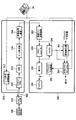
最初に図1を参照すると、本発明の原理による超音波システムがブロック図の形式で図示されている。プローブは、2次元アレイトランスデューサ500及びマイクロビーム形成器502を有するシステムと結合する。マイクロビーム形成器502は、2次元アレイトランスデューサ500の素子(「パッチ」)からなる群に印加される信号を制御する回路を有し、かつ各群の素子によって受信されるエコー信号の一部処理を実行する。プローブでのビーム形成は有利となるように、前記プローブと当該超音波システムとの間のケーブル503中での導体数を減らす。プローブでのビーム形成は特許文献9及び10に記載されている。
Referring initially to FIG. 1, an ultrasound system according to the principles of the present invention is illustrated in block diagram form. The probe is coupled to a system having a two-
前記プローブは、当該超音波システムのスキャナ310と結合する。スキャナ310はビーム形成制御装置312を有する。ビーム形成制御装置312は、ユーザー制御36に応答し、かつ、伝送ビームのタイミング、周波数、方向、及び集束について支持するマイクロビーム形成器502へ制御信号を供する。ビーム形成制御装置312はまた、アナログ−デジタル(A/D)変換器316及びビーム形成器116の制御によって、スキャナ310によって受信されるエコー信号のビーム形成をも制御する。前記プローブによって受信されるエコー信号は、スキャナ310内のプリアンプ及びTGC(時間−ゲイン制御)回路314によって増幅される。続いてデジタル化されたエコー信号は、ビーム形成器116によって十分に操縦及び集束されたビームに生成される。前記エコー信号は続いて、デジタルフィルタリング、Bモード検出、及びドップラー処理を実行し、かつ他の信号処理−たとえば調和分離、周波数合成を介したスペックルの減少、及び他の必要な画像処理−をも実行することもできる画像処理装置318によって処理される。
The probe is coupled to the
スキャナ310によって生成されるエコー信号はディスプレイサブシステム320と結合する。ディスプレイサブシステム320は、所望の画像形式における表示のために前記エコー信号を処理する。前記エコー信号は画像ライン処理装置322によって処理される。画像ライン処理装置322は、前記エコー信号をサンプリングし、複数のビームのセグメントを完全なライン信号につなぎ合わせ、かつ信号対雑音比の改善又は流れの持続のためにライン信号を平均化することが可能である。画像ラインは、当業者に知られている、R-θ変換を実行するスキャンコンバータ324によって、所望の画像形式に走査されて変換される。続いて前記画像は画像メモリ328に記憶される。画像メモリ328から前記画像をディスプレイ150上に表示することができる。メモリ中の前記画像はまた、該画像によって表示されるグラフィックスで覆われる。前記グラフィックスは、ユーザー制御36に応答するグラフィックス生成装置330によって生成される。個々の画像又は画像シーケンスは、画像ループ又はシーケンスの取り込み中にシネメモリ326内に記憶されて良い。リアルタイムでの体積イメージングでは、ディスプレイサブシステム320もまた、3DのEFOVサブシステム304(図8及び図9で詳述する)内の3D像レンダリング処理装置をも有する。前記3D像レンダリング処理装置は、リアルタイムで3次元像をレンダリングするため、ディスプレイ150上で表示を行うため画像メモリ328と結合する画像ライン処理装置322から画像ラインを受け取る。
The echo signal generated by the
本発明の原理によると、3DEFOVサブシステムは、拡張視野像イメージング用の像を生成する。EFOV像は、特許文献1及び2に記載されているように2次元の平面像であって良く、又は3D像であっても良い。複数のEFOV像は、シネメモリ326によって供される像データを用いる運動推定器302でプローブの運動を推定することによって集められる。運動推定器302は、たとえば特許文献11に記載されているようなMSADブロックマッチングと呼ばれる手法を用いて、連続的に取得された像のデータを記録することによって、患者の身体に沿ったプローブの運動を追跡することができる。必要に応じて他の運動推定器−たとえば非剛体記録(non-rigid body registration)−が用いられても良い。ブロックマッチング法は、少なくとも一部が重なっている連続して取得された像の間での変位を計算する。その変位が各異なる面の向きにおける像について計算されるとき、変位ベクトルの大きさも方向も、運動推定器302によって3次元的に計算することができる。変位ベクトルは、プローブが動く際に各異なる面から取得される像の相対的な位置設定を行うため、位置情報をEFOVサブシステム304に供する。連続する像が、EFOVサブシステム304によって相互に対して適切に位置設定されているときには、幾何学的に正確な2次元又は3次元のEFOV像が生成される。
In accordance with the principles of the present invention, the 3DEFOV subsystem generates an image for extended field image imaging. The EFOV image may be a two-dimensional planar image as described in
本発明のEFOVイメージング法は、2DアレイプローブがEFOV像を取得する際の運動を表す斜視図である図2を最初に参照することによってより十分に理解することが可能である。図2では、簡明を期すため、周囲のプローブケースとトランスデューサ積層体が省略された2Dアレイトランスデューサ500が図示されている。図2において、2Dアレイトランスデューサ500は、患者の皮膚表面2に沿って移動し、かつ移動する際に像データを取得する。2Dアレイトランスデューサ500は大きな矢印の方向に移動している。この大きな矢印は、「前」方向で、かつプローブの後ろである「後」方向から遠ざかる方向である。運動方向の両側は「左」方向と「右」方向である。
The EFOV imaging method of the present invention can be more fully understood by first referring to FIG. 2, which is a perspective view illustrating the motion of the 2D array probe as it acquires an EFOV image. FIG. 2 shows a
これらの方向を示す参照記号に留意した上で図3を参照する。図3は2つの面”S”(サジタル面)と”T”(横断面)を図示している。面内では、プローブが矢印に示された方向に移動することで像が取得される。この例では2つの面は長方形の形状で表されている。しかし所与の実施例においては、2つの面は他の形状−たとえば扇形又は台形−を有しても良い。2つの面SとTは、2Dアレイトランスデューサ500から「下」方向に延在するように見える。2Dアレイトランスデューサ500は、多くの像平面及び特にアレイトランスデューサの下の全体積を走査することが可能であるが、この実施例では、2つの面SとTの走査しか必要とされない。2つの面の走査しか必要ないということは、前記2つの面の走査を交互に行うことによって、迅速に連続した像の取得が可能であることを意味する。
With reference to the reference symbols indicating these directions, reference is made to FIG. FIG. 3 illustrates two planes “S” (sagittal plane) and “T” (cross section). In the plane, the image is acquired by moving the probe in the direction indicated by the arrow. In this example, the two faces are represented by a rectangular shape. However, in a given embodiment, the two surfaces may have other shapes, such as a sector or a trapezoid. The two faces S and T appear to extend in the “down” direction from the
取得フレーム速度が高いということは、像と像の間では相対的に小さな運動しか起こらず、かつ連続する像の像データ内容において顕著な重なりが存在することで、像データ内において同一性を発見し、かつ運動ベクトルを計算する能力が改善され、かつ校正された体積の以降の再構成についての空間サンプリングが改善されることを意味する。連続する像の間での変位は正確に推定することが可能で、かつ、相互の像の位置を正しく設定することによって、幾何学的に厳密なEFOV像を集めることができる。 The high acquisition frame rate means that there is relatively little movement between images and that there is significant overlap in the image data content of successive images, thus finding the identity in the image data. And the ability to calculate motion vectors is improved and the spatial sampling for subsequent reconstruction of the calibrated volume is improved. The displacement between successive images can be accurately estimated, and geometrically exact EFOV images can be collected by setting the positions of the images relative to each other.
図3の例では、2種類のEFOV像が形成されて良い。一の像は、2Dアレイトランスデューサが矢印の方向に移動する際に取得される一連のS面の像で形成される。後ろから前へ向かう方向での運動は、連続的に取得されたS面の像の内容に反映される。上下運動もまたS面の像の内容に反映される。連続するT面の像の間での変位は、左方向又は右方向の運動を明らかにし、かつ上下の運動をも明らかにする。よってこれらの変位の推定は、一のS面の像から次のS面の像への相対的変位のベクトルを生成するのに用いられる。続いて一連のS面の像は、位置合わせされた状態で重ね合わせられ、かつ一つにまとめられることで、2次元EFOV像が生成される。この2次元EFOV像は矢印の方向において最長寸法を有する。1Dトランスデューサを用いた従来のEFOVイメージングとは異なり、本発明の原理によると、プローブの運動をS面に対して厳密に位置あわせする必要がないことを明記することは重要である。たとえ運動がこの面からずれているとしても、このずれはT面によって追跡されることで、十分校正されたパノラマ像を生成することができる。 In the example of FIG. 3, two types of EFOV images may be formed. One image is formed by a series of S-plane images acquired as the 2D array transducer moves in the direction of the arrow. The movement in the direction from the back to the front is reflected in the content of the S-plane image acquired continuously. Vertical motion is also reflected in the content of the S-plane image. Displacement between successive T-plane images reveals leftward or rightward motion and also reveals up and down motion. Thus, these displacement estimates are used to generate a relative displacement vector from one S-plane image to the next S-plane image. Subsequently, a series of S-plane images are superposed in a registered state and combined into one to generate a two-dimensional EFOV image. This two-dimensional EFOV image has the longest dimension in the direction of the arrow. Unlike conventional EFOV imaging using 1D transducers, it is important to specify that according to the principles of the present invention, the probe motion need not be strictly aligned with respect to the S-plane. Even if the motion deviates from this plane, this deviation can be tracked by the T plane to produce a fully calibrated panoramic image.
図3の例において取得可能な他のEFOV像は、連続的に取得されたT面の像をまとめることによって生成された3DEFOV像である。連続的に取得されるT面の像の間での変位ベクトルは、前述したS面のT面の像情報から計算され、かつ続いて一連のT面の像を相互に適切な位置設定を行うのに用いられる。T面の像が矢印の方向において取得され続けるので、一連のT面の変位が先に取得されて位置設定された像の前方となるにつれて、矢印の方向における3次元像の厚さは大きくなる。よって3DのEFOV像は、T面に垂直な最長寸法を有する。 Another EFOV image that can be acquired in the example of FIG. 3 is a 3DEFOV image generated by combining the images of the T-plane acquired continuously. The displacement vector between continuously acquired T-plane images is calculated from the above-mentioned S-plane T-plane image information, and then a series of T-plane images are appropriately positioned with respect to each other. Used for As the T-plane image continues to be acquired in the direction of the arrow, the thickness of the three-dimensional image in the direction of the arrow increases as the series of T-plane displacements are ahead of the previously acquired and positioned image. . Therefore, the 3D EFOV image has the longest dimension perpendicular to the T plane.
同時に2つの像を生成することが可能である。その理由は、2DのEFOV像と3DのEFOV像のいずれについても、平面像は同じように取得されるからである。たとえば、一連のT面の像によって切り取られる(intercepted)細胞組織の拡張体積像が取得され、かつこの体積の中心から下へ向かって延在した切断面が、一連のS面のEFOVによって生成されて良い。S面とT面は物理的なトランスデューサアレイ500の特定寸法に関連づけられる必要はない。しかしS面とT面は、S面がいずれかの寸法に沿った向きをとり、かつT面がこの向きに垂直となるように取得されて良い。S面は、図3に図示されているように2Dアレイの下で中心をとる必要はない。S面は、中央のいずれかの側部で、又は傾いた角度で取得されることで、3DのEFOV像の3D像の様々な向きの切断面でEFOV像を生成しても良い。S面及びT面の開口部の選択に依存して、T面は必ずしもS面と垂直でなくても良い。
It is possible to generate two images at the same time. The reason is that the planar image is acquired in the same way for both the 2D EFOV image and the 3D EFOV image. For example, an expanded volumetric image of the tissue that is intercepted by a series of T-plane images is acquired, and a cut plane extending downward from the center of this volume is generated by a series of S-plane EFOVs. Good. The S and T planes need not be associated with specific dimensions of the
図4の例では、2次元アレイの主要面に平行な面が既知であるので、第3取得面である”C” 面(断面)が加わる。C面の連続する像の間での変位は上述したように計算される。そしてその変位は、後ろから前へ向かう方向と左右方向の両方における2Dアレイトランスデューサの運動を表す。連続するT面の像が上下方向における変位情報を供するので、3次元変位ベクトルは、S面からの如何なる情報も必要とせずに計算可能である。このことは、S面からの像をまとめることによって構成される2DのEFOV像については、可視化のためにS面の取得が最適化されて良く、かつ変位の測定のためにT面とC面の取得が最適化されて良いことを意味する。あるいはその代わりに、一連のT面が3DのEFOV像内にまとめられる場合には、C面とS面の取得が変位測定のために最適化される一方で、T面の取得が可視化用に最適化されて良い。変位測定の像のサイズを小さくして良いし、あるいは変位測定の像ラインの間隔を増大させながら、たとえば同時に、像平面を大きくして、かつ高解像度の像用の高ライン密度にしても良い。 In the example of FIG. 4, since a plane parallel to the main surface of the two-dimensional array is known, a “C” plane (cross section) as a third acquisition plane is added. The displacement between successive images of the C plane is calculated as described above. The displacement represents the motion of the 2D array transducer both in the direction from back to front and in the left-right direction. Since successive T-plane images provide displacement information in the vertical direction, a three-dimensional displacement vector can be calculated without requiring any information from the S-plane. This means that for 2D EFOV images constructed by combining images from the S plane, the acquisition of the S plane may be optimized for visualization, and the T and C planes for displacement measurement. Meaning that the acquisition of may be optimized. Alternatively, if a series of T-planes are grouped together in a 3D EFOV image, C- and S-plane acquisition is optimized for displacement measurements, while T-plane acquisition is used for visualization. May be optimized. The size of the image for displacement measurement may be reduced, or the distance between the image lines for displacement measurement may be increased, for example, at the same time, the image plane may be increased and a high line density for a high resolution image may be obtained. .
図4の例においては、必要に応じて一連のC面の像から2DのEFOV像をまとめることによって構成することも可能である。C面が取得されるとき、如何なる追加的な音響伝送を行わなくても、C面とプローブとの間での体積データが取得される。体積データの一連のシーケンスは、全体の取得プロセスにおけるそのプローブの6つの自由度(3つの並進自由度と3つの回転自由度)を見つける3D記録によって位置合わせされて良い。これにより、3D又は2DのEFOV像の正確な再構成が可能となる。 In the example of FIG. 4, a 2D EFOV image can be combined from a series of C-plane images as necessary. When the C plane is acquired, volume data between the C plane and the probe is acquired without any additional acoustic transmission. A series of volume data sequences can be aligned by a 3D recording that finds the probe's six degrees of freedom (three translational and three rotational degrees of freedom) in the overall acquisition process. This allows accurate reconstruction of 3D or 2D EFOV images.
面に垂直な運動によって、像平面の内容が、一の面から他の面へ急速に相関を失わせることで、その方向における変位の推定に問題を生じさせてしまうことは、知られている。しかし多数の異なった向きの面を利用することで、他の像平面においてもそのような高さの変位を起こすことが可能となる。ここで、像間での相関は高いままであり、かつ依然として変位を正確に推定することができる。 It is known that motion perpendicular to a surface causes the image plane contents to quickly lose correlation from one surface to the other, causing problems in estimating displacement in that direction. . However, by utilizing a number of differently oriented surfaces, it is possible to cause such height displacements in other image planes. Here, the correlation between the images remains high and the displacement can still be estimated accurately.
図5は、T面、S面、及びC面を用いた体内の血管VのEFOV走査を図示している。この例では、EFOV像が血管Vの相当な長さにわたって生成されることで、その血管のほとんどすべての特性を1つの像で診断することが可能となる。2Dアレイトランスデューサプローブが動く際、S面は血管Vの中心に位置合わせされた状態を保持する。それによりその血管の垂直方向の中心から下へ向かうように切断された面の像を生成することができる。C面の深さは、血管が体内において一定の深さにとどまる場合には、その血管の水平方向の中心を切断し続けるように設定される。T面は、プローブが動く際、血管とその周辺を切断し続ける。この構成はたとえば、多数のEFOV像、一連のT面の像からの血管VのEFOV像、及び一連のT面の像とC面の像から直交するような向きをとる2D切断面を同時に生成するのに用いられて良い。 FIG. 5 illustrates an EFOV scan of a blood vessel V in the body using the T, S, and C planes. In this example, the EFOV image is generated over a considerable length of the blood vessel V, so that almost all the characteristics of the blood vessel can be diagnosed with one image. As the 2D array transducer probe moves, the S-plane remains aligned with the center of the blood vessel V. As a result, an image of a surface cut from the vertical center of the blood vessel toward the bottom can be generated. The depth of the C plane is set so as to continue cutting the horizontal center of the blood vessel when the blood vessel remains at a constant depth in the body. The T-plane continues to cut the blood vessel and its surroundings as the probe moves. This configuration, for example, generates multiple EFOV images, EFOV images of blood vessels V from a series of T-plane images, and 2D cut planes that are oriented orthogonally from a series of T- and C-plane images. Can be used to
図6a-6cは、様々な向きをとる一連の面からすぐに決定することのできる様々な面内変異を図示している。図6aに図示されているように、プローブが矢印の方向に移動するときには、一のS面の像において前に現れている構造s1は、構造の連続する位置s1とs2との間の小さな矢印で示されているように、次の連続するS面の像において後へ移動したように見える。上の構造と下の構造も、一連の像におけるその構造の相対位置からすぐに識別可能である。図6Bは、プローブが左へ移動するとき、一のT面の像におけるs1構造の位置が一連のT面の像におけるs2の位置に変化することを示している。上下の変位もまた一連のT面の像からすぐに識別可能である。図6Cに図示されているように、一連のC面の像は、プローブの前から後ろへの運動及び左右の運動をすぐに明らかにする。 Figures 6a-6c illustrate various in-plane variations that can be readily determined from a series of planes in various orientations. As shown in FIG. 6a, when the probe moves in the direction of the arrow, the structure s 1 that appears before in the image of one S-plane is between the successive positions s 1 and s 2 of the structure. It appears to have moved backwards in the next continuous S-plane image, as indicated by the small arrow. The upper and lower structures can also be readily identified from their relative positions in the series of images. FIG. 6B shows that when the probe moves to the left, the position of the s 1 structure in one T-plane image changes to the position of s 2 in a series of T-plane images. Vertical displacements can also be readily identified from a series of T-plane images. As illustrated in FIG. 6C, a series of C-plane images immediately reveals front-to-back and left-right motion of the probe.
図7は、図1の運動推定器302と3DのEFOVサブシステム304との間の接続を示すブロック図である。この実施例では、シネメモリ326は、受信した平面像をEFOV像に利用する前に記憶する。Bモード像は、この例では運動の推定に用いられる。なぜならBモード像は、ドップラー信号のパルス化又はフラッシュアーティファクトを示さないからである。運動推定器は、一連のBモード像を解析し、像間での変位ベクトルを推定する。これらの運動の推定は、3DのEFOVサブシステムへ送られる。前記3DのEFOVサブシステムでは、これらの運動の推定は、取得された像を相対的に位置合わせするのに用いられる。位置合わせされた像は、シネメモリから3DのEFOVサブシステムへ転送される、ドップラー像及び/又はBモード像であって良い。運動の推定はまた、グラフィックス生成装置330用の運動の情報を生成する。グラフィックス生成装置330は、後述するように画像ディスプレイ上の1つ以上の運動を示すアイコンを表示するためにその情報を利用する。
FIG. 7 is a block diagram illustrating the connection between the
図8は、本発明の原理によって構築された3DのEFOVサブシステムのさらなる詳細を表すブロック図である。運動推定器302からの運動の推定は、2Dモザイク作成器310、3Dドップラー体積再構成器308、及び3DのBモード体積再構成器306と結合する。シネメモリ326内に記憶されるBモード像は、2Dモザイク作成器310、運動推定器302、及び3DのBモード体積再構成器306へ供給される。ドップラー像は3Dドップラー体積再構成器308へ供給される。3Dドップラー体積再構成器308は、特許文献12に記載された3D像レンダリング装置と同じように機能する。特許文献12に記載された3D像レンダリング装置では、運動推定器の運動の推定によって導かれるようにして互いの向きが定められた複数の2D像から3D像がレンダリングされる。1つ又は2つの3Dレンダリング−これは供給される像情報に依存する−は3Dディスプレイサブシステム330と結合する。3Dディスプレイサブシステム330では、Bモード及びドップラーレンダリングの細胞組織と流れの像は、特許文献12に記載されているように、その細胞組織と流れの像の3D像を生成するために1つにまとめられる。様々な3D可視化の改善−たとえば多断面再構成やサーフェスレンダリング−はまた、3Dディスプレイサブシステムで適用されても良い。3D像は表示ために像メモリ328へ供給される。2Dモザイク作成器310は、部分的に重なる3D像フレームを組み合わせることで、特許文献1に記載されたように2DのEFOV像を生成する。2DのEFOV像は像メモリ328へ供給される。また2DのEFOV像は、独立して表示されて良いし、又は3DのEFOV像と共に表示されても良い。たとえば3Dディスプレイサブシステム330は、体内の体積の3DのEFOV像を供することが可能な一方で、2Dモザイク作成器は、3D体積を貫通する平面スライスの2DのEFOV像を供する。
FIG. 8 is a block diagram representing further details of a 3D EFOV subsystem constructed in accordance with the principles of the present invention. Motion estimation from
図9は、本発明の実施例に係る3D体積再構成器のさらなる詳細を表すブロック図である。図示された3D体積再構成器306,308は、順再構成器(forward reconstructor)332と逆再構成器(backward reconstructor)334の手段によって順データ(forward data)と逆データ(backward data)の両方を有する3D像を同時に生成して良い。3D体積は順マッピング(forward mapping)によって再構成される。順マッピングでは、入力データは、運動の推定によって供される変換行列に依存して、直接的に出力ボクセルにマッピングされる。この手法は、入力2D像と同じ解像度を有しながら速い応答を供することが可能である一方で、新たな像データが受信されるとすぐ、その新たな像データはレンダリングされた体積に加えられるので、その結果生成される3D像は再構成された体積中に穴を有する恐れがある。他方、後方再構成器逆マッピング(backward mapping)法は逆変換行列を利用することで、より詳細な出力ボクセルが補間の手段によって入力データから生成される。逆マッピングによる3D再構成では、再構成された体積中に現れる穴は少なくなるが、応答は遅くなる。なぜなら面間の像データが補間可能となる前に、再構成は走査からのすべての入力データを待たなければならないからである。利用可能な適切な補間方法は次式で表される。
FIG. 9 is a block diagram showing further details of the 3D volume reconstructor according to the embodiment of the present invention. The illustrated

図10a-10dは、どのようにして患者が走査されることで3DのEFOV像が超音波システムのディスプレイ上に現れるのかを図示している。プローブが図10aの矢印によって示された方向に移動することで、血管Vと交差する像面は順次、走査及び表示されている体積100の前面に追加される。プローブは患者の皮膚に沿った運動を続けているので、より多くの面が走査されて体積の前部に追加され、かつその体積は図10bの長くなったEFOV体積100で示されているように、この方向に成長する。プローブがまたさらに移動することで、前方へ向かうより多くの面が体積に追加される。その体積は、図10cに図示されているように成長する。上で説明したように、新たな面の各々は、運動の推定、すなわち最後に取得された面から現在の面までの変位の推定によって、その体積の前の面に対して位置設定される。この変位情報は、1つ以上の直交する走査面−たとえば図3、4、及び5に図示されている像平面C又はS−の像データから計算されて良い。よって新たに取得された面の各々は、過去に取得された面及び体積に対する正しい幾何学的関係を考慮した上で追加される。よってその結果生成された体積は、幾何学的に正確で、かつその体積で示された構造の定量的測定を支援することができる。図10dは、本発明によって取得及び生成された実際の3DのEFOV像を図示したものである。(図10dでは簡明を期すため、その像の画素の黒白グレイスケール範囲では、通常の黒地の白(white-on-black)が反転している。)
図11は、本発明の原理によって構築された超音波システムのEFOVディスプレイ50を図示している。EFOVディスプレイ50は、超音波プローブを動かしてEFOV像を取得する医療者へガイダンスを供する。この例では、2DのEFOV像66は、図3のサジタル面S内で取得された一連の成分の像をまとめることで生成される。プローブが動く際、成分の像は、サジタル面Sと横断面Tの両方において連続的に取得される。両面での像は、そのプローブの移動を追跡するため、運動推定器302によって用いられる。横断成分の像とサジタル成分の像の一部又は全部はディスプレイの上部に示される。52は最近取得された横断面の像であり、54は最近取得されたサジタル面の像である。グラフィックス生成装置330によって生成されたグラフィックアイコン56と58は、成分の像52と54の上に表示され、かつ、対応する面の向きを色で示すようにハイライトされたバーを有する。この例では、面の向きは、その面がトランスデューサ500の上方から横向きに見られているように表示されている。
FIGS. 10a-10d illustrate how a 3D EFOV image appears on the display of the ultrasound system as the patient is scanned. As the probe moves in the direction indicated by the arrow in FIG. 10a, the image plane intersecting the blood vessel V is sequentially added to the front of the
FIG. 11 illustrates an
本発明の原理によると、2つのプローブ運動インジケータ6がディスプレイ50の中心に示されている。各プローブ運動インジケータは、範囲を明示するカラーバー60,62及びその範囲内の点を示す小さな三角形(矢印で示されている)を有する。この例では、各プローブ運動インジケータは、プローブが動いている速さを医療者に示し、2つのプローブ運動インジケータはそれぞれ横断面とサジタル面の運動を表している。各バーの上方のグラフィックの三角形の位置は、運動推定器302及びフレームが取得される既知の期間によって推定されるフレーム間での変位から計算される。これらの期間及び間隔の値を知ることで、所与の方向における速度を直接推定することが可能となる。この例では、医療者は、図3に図示されているように、前方のサジタル方向にプローブを動かすことによってEFOV走査を実行するので、横断面の運動インジケータは、医療者に対して、その医療者のプローブが身体に沿った直線内に位置しているか、又は左若しくは右にドリフトしているのかを知らせる。この例において、小さな三角形がカラーバー60全体の中心のままとどまるときには、プローブは、前方へ向かう直線に沿って動いている。このことは、EFOV像66を生成するのに用いられる一連のサジタル成分の像の各々が実質的に同じ像平面内にあることを意味している。しかしプローブが左右に動き始める場合、一連の成分の像は共面ではなくなり、かつそれに対応して小さな三角もカラーバーの中心から左右に移動することで、この運動にずれが存在することを示す。プローブの左右への移動が速くなればなるほど、小さな三角形のカラーバーの中心からの表示されたずれは大きくなる。プローブが前方へ向かう直線に沿った移動に再び戻るとき、その小さな三角形は再び中心にとどまる。
In accordance with the principles of the present invention, two probe motion indicators 6 are shown in the center of the
この例では、カラーバー62を有するサジタル方向のプローブ運動インジケータは前方方向での速度を示している。走査が始まり、かつプローブが患者上で静止する前に、小さな三角形はカラーバーの左端の上方であるゼロ速度地点に位置している。医療者がプローブを動かしはじめ、かつその速さが増大すると、小さな三角形は右へ動き始めることで、サジタル方向の前方方向でのそのプローブの速さを示す。均一なEFOV像のためには、均等に分けられた時間的及び空間的な間隔で成分の像が取得されるように、一定の速さでプローブを動かすことが望ましい。所与の実施例において利用可能なパラメータ−たとえば像の所望の長さ、利用可能なシネメモリの大きさ、成分の像の重なりの程度等−を用いることによって、プローブが所望の速さで動いているときに小さな三角形がカラーバーの中心に位置するように、医療者は自己のシステムを設定することができる。よって、所望の速さでまっすぐに伸びた組織を走査するために、医療者は、プローブが動いている際、2つの小さな三角形のいずれもが各対応するカラーバーの中心にとどまっているのを見ることしか必要とされない。このような小さな三角形の位置設定を維持することによって、医療者は自身が望む高品質のEFOV像を得る。一部のユーザーが取得中に表示された像を夢中になって見てしまう恐れがあるので、プローブの動きが速すぎたり遅すぎたりするときには、聞き取ることのできる警告音−たとえばベル音−を供することも可能である。
In this example, the sagittal probe motion indicator with the
プローブ運動インジケータのいずれか又は両方は、速度以外の単位で指定されて良いことに留意して欲しい。たとえば医療者は、身体の上の50cmの距離にわたってEFOV像を取得することを決定しても良い。よってサジタル方向のプローブ運動インジケータバー62は、この距離へ向かう進行程度を示すように設定されることで、カラーバー62の左側に位置するゼロから始まって、右側に位置するカバーされた距離である50cmまで続けられて良い。医療者が走査を開始すると、小さな三角形は、開始点からのプローブの変位によって移動し始める。小さな三角形が、完全にカラーバーの右端まで移動したとき、医療者は50cmの走査が完了したことを知る。プローブ運動インジケータでの指定が可能な他の単位はたとえば時間である。
Note that either or both of the probe motion indicators may be specified in units other than velocity. For example, a medical practitioner may decide to acquire EFOV images over a distance of 50 cm above the body. Thus, the sagittal probe
図12は、本発明の原理によって構築された超音波システムの第2のEFOVディスプレイ50を図示している。第2のEFOVディスプレイ50は、超音波プローブを動かしてEFOV像を取得する医療者へガイダンスを供する。この例では、ディスプレイは、成長しているときのEFOV像を表示せず、取得されたときの成分の像52と54のみを表示する。まさに成分の像が、運動推定器によるプローブの動きの追跡に用いられる。これまでの例のように、面の向きを表すアイコン56,58が、各対応する成分の像52,54の上方に図示されている。
FIG. 12 illustrates a
ディスプレイ領域内では、EFOV走査が実行される際にプローブが横断する経路のグラフィック追跡記録が表示される。この例では、追跡記録70は一連の小さな点によって形成される。追跡記録70の下にある向きを示す矢印は、横断方向(左右)及びサジタル方向(上下)を表す。追跡記録70は、運動推定器302によってなされた変位の推定から生成される。一連の円72は、追跡記録70に沿って設けられる。一連の円72は、追跡記録70によって示される経路に沿って1cmずつ増えるように設けられている。あるいはその代わりに、所与の数の成分のフレームが取得された後に、又は、走査中にさらに時間期間が経過した後に、円72が設けられることで、プローブの運動の均一性を医療者に検知させることができる。追跡記録70の端部で、大きな点8がプローブの運動中での現在のプローブ位置を示している。追跡記録70の経路は、たとえばS面とT面との交差軸、及び、プローブの位置設定を行う参照点として2Dアレイ上の原点を用いることによって、アレイの特定地点に関連づけられて良い。
Within the display area, a graphical tracking record of the path traversed by the probe when an EFOV scan is performed is displayed. In this example, tracking
この例では、3DのEFOV像は一連の横断面52をまとめることによって作成される。この図示された例では、走査されている細胞組織の体積は、横断成分の像52の横方向断面とサジタル成分の像54の縦方向断面とで表される血管Vを有する。医療者は、自分のプローブの動きを、図に示されているように、血管Vの横方向断面が、連続する横断成分の像52の各々の中央部で中心をとる状態を保つように導くことが可能である。このとき一連のサジタル成分の像54は、血管Vの主要な縦方向の切断面を示し続ける。それにより医療者は、血管Vを完全に含む3DのEFOV像を取得するように導かれる。導かれた像の取得が完了した後、医療者は、3DのEFOV像−たとえば図10dの図−の閲覧に切り替えることができる。
In this example, a 3D EFOV image is created by combining a series of
好適実施例は、プローブが移動する際に所望の像平面全体にわたってビームを電子的に操縦する2Dアレイトランスデューサを利用しているが、EFOVの走査と像取得はまた、プローブが動く際にそのプローブ内で1Dアレイを前後に振動させるメカニカル3D走査プローブによって実行されても良い。たとえば特許文献13に示されている3Dメカニカルプローブは、本発明によるEFOV走査に用いられて良い。動く1Dアレイが該1Dアレイの振動掃引における所与の位置に到達するたびに、そのアレイの位置の像平面の向きで像を取得することができる。アレイが有する1つ又は数個の近くにある素子を、そのアレイが振動する際に、直交する面を連続的に走査するように連続的に動作させることができる。プローブが患者の皮膚に沿って動く際に、プローブがEFOV走査において動くと、これらの2つの像取得は2つの異なる面を連続的に走査する。 While the preferred embodiment utilizes a 2D array transducer that electronically steers the beam across the desired image plane as the probe moves, EFOV scanning and image acquisition is also possible as the probe moves. It may be implemented by a mechanical 3D scanning probe that oscillates the 1D array back and forth within. For example, the 3D mechanical probe shown in Patent Document 13 may be used for EFOV scanning according to the present invention. Each time a moving 1D array reaches a given position in the vibrational sweep of the 1D array, an image can be acquired with the orientation of the image plane at that array position. One or several nearby elements of an array can be operated continuously to continuously scan orthogonal planes as the array vibrates. As the probe moves along the patient's skin, these two image acquisitions sequentially scan two different planes as the probe moves in an EFOV scan.
Claims (15)
対象物の表面に沿って前進方向に動かすことが可能なアレイトランスデューサを有する超音波プローブ;
前記アレイトランスデューサと結合するビーム形成器であって、前記プローブが前記表面に沿って前記前進方向に動かされる際に前記アレイに対して各異なる面の向きをとる複数の像平面を繰り返し走査するように前記プローブを制御する、ビーム形成器;
前記アレイトランスデューサから受信した信号に応答して、前記プローブが動かされる際に前記各異なる面の向きをとる一連の像を生成する、像処理装置;
一連の像に応答してプローブ運動の推定を行う運動推定器;
前記プローブ運動の推定に応答して一連の像からEFOV像を生成するように動作するEFOVサブシステム;
前記運動推定器に応答して前記前進方向及び該前進方向に対して横方向でのプローブ運動の表示を生成するプローブ運動インジケータ;及び、
前記EFOVサブシステムと前記プローブ運動インジケータに応答して、前記プローブが動かされる際の前記プローブ運動インジケータと前記EFOV像を表示するディスプレイ;
を有する超音波診断イメージングシステム。 An ultrasound diagnostic imaging system that generates guided extended field of view (EFOV) images:
An ultrasonic probe having an array transducer capable of moving in a forward direction along the surface of the object;
A beamformer coupled to the array transducer for repeatedly scanning a plurality of image planes oriented in different planes relative to the array as the probe is moved in the advance direction along the surface Controlling the probe to a beamformer;
An image processing device that generates a series of images that are oriented in the different planes as the probe is moved in response to signals received from the array transducer;
A motion estimator that estimates the probe motion in response to a sequence of images;
An EFOV subsystem that operates to generate an EFOV image from a series of images in response to an estimate of the probe motion;
A probe motion indicator that is responsive to the motion estimator to generate an indication of probe motion in the forward direction and transverse to the forward direction ; and
A display that displays the probe motion indicator and the EFOV image as the probe is moved in response to the EFOV subsystem and the probe motion indicator;
An ultrasound diagnostic imaging system.
前記横方向は前記前進方向に対して横を向く方向である、
請求項2に記載の超音波診断イメージングシステム。 The nominal travel path has the forward direction, and the lateral direction is a direction that is transverse to the forward direction;
The ultrasonic diagnostic imaging system according to claim 2.
前記成分像の表示領域では、EFOV像の生成に用いられる最近取得された像が表示される、
請求項1に記載の超音波診断イメージングシステム。 The display further has a component image display area;
In the component image display area, a recently acquired image used to generate an EFOV image is displayed.
The ultrasonic diagnostic imaging system according to claim 1.
前記成分像の表示領域では、プローブ運動の推定の生成に用いられる最近取得された像が表示される、
請求項1に記載の超音波診断イメージングシステム。 The display further has a component image display area;
In the component image display area, a recently acquired image used to generate a probe motion estimate is displayed.
The ultrasonic diagnostic imaging system according to claim 1.
前記第2の成分像の表示領域では、プローブ運動の推定の生成に用いられる最近取得された像が表示され、
第1の成分像と第2の成分像は、各異なる向きの像平面から前記超音波プローブによって取得される、
請求項13に記載の超音波診断イメージングシステム。
The display further has a display area of a second component image;
In the display area of the second component image, a recently acquired image used to generate an estimate of the probe motion is displayed,
The first component image and the second component image are acquired by the ultrasonic probe from the image planes in different directions,
The ultrasonic diagnostic imaging system according to claim 13.
Applications Claiming Priority (3)
| Application Number | Priority Date | Filing Date | Title |
|---|---|---|---|
| US5895108P | 2008-06-05 | 2008-06-05 | |
| US61/058,951 | 2008-06-05 | ||
| PCT/IB2009/052322 WO2009147621A2 (en) | 2008-06-05 | 2009-06-02 | Extended field of view ultrasonic imaging with guided efov scanning |
Publications (2)
| Publication Number | Publication Date |
|---|---|
| JP2011521763A JP2011521763A (en) | 2011-07-28 |
| JP5508401B2 true JP5508401B2 (en) | 2014-05-28 |
Family
ID=41398623
Family Applications (1)
| Application Number | Title | Priority Date | Filing Date |
|---|---|---|---|
| JP2011512262A Active JP5508401B2 (en) | 2008-06-05 | 2009-06-02 | Ultrasound imaging of extended field of view by guided EFOV scanning |
Country Status (6)
| Country | Link |
|---|---|
| US (1) | US8852107B2 (en) |
| EP (1) | EP2288935A2 (en) |
| JP (1) | JP5508401B2 (en) |
| CN (1) | CN102047140B (en) |
| RU (1) | RU2519811C2 (en) |
| WO (1) | WO2009147621A2 (en) |
Families Citing this family (56)
| Publication number | Priority date | Publication date | Assignee | Title |
|---|---|---|---|---|
| US10864385B2 (en) | 2004-09-24 | 2020-12-15 | Guided Therapy Systems, Llc | Rejuvenating skin by heating tissue for cosmetic treatment of the face and body |
| US8535228B2 (en) | 2004-10-06 | 2013-09-17 | Guided Therapy Systems, Llc | Method and system for noninvasive face lifts and deep tissue tightening |
| US8444562B2 (en) | 2004-10-06 | 2013-05-21 | Guided Therapy Systems, Llc | System and method for treating muscle, tendon, ligament and cartilage tissue |
| US8133180B2 (en) | 2004-10-06 | 2012-03-13 | Guided Therapy Systems, L.L.C. | Method and system for treating cellulite |
| US11883688B2 (en) | 2004-10-06 | 2024-01-30 | Guided Therapy Systems, Llc | Energy based fat reduction |
| US8663112B2 (en) | 2004-10-06 | 2014-03-04 | Guided Therapy Systems, Llc | Methods and systems for fat reduction and/or cellulite treatment |
| US11235179B2 (en) | 2004-10-06 | 2022-02-01 | Guided Therapy Systems, Llc | Energy based skin gland treatment |
| US9827449B2 (en) | 2004-10-06 | 2017-11-28 | Guided Therapy Systems, L.L.C. | Systems for treating skin laxity |
| US8690778B2 (en) | 2004-10-06 | 2014-04-08 | Guided Therapy Systems, Llc | Energy-based tissue tightening |
| US9694212B2 (en) | 2004-10-06 | 2017-07-04 | Guided Therapy Systems, Llc | Method and system for ultrasound treatment of skin |
| US11207548B2 (en) | 2004-10-07 | 2021-12-28 | Guided Therapy Systems, L.L.C. | Ultrasound probe for treating skin laxity |
| US11724133B2 (en) | 2004-10-07 | 2023-08-15 | Guided Therapy Systems, Llc | Ultrasound probe for treatment of skin |
| EP2131212A3 (en) * | 2008-06-05 | 2011-10-05 | Medison Co., Ltd. | Non-Rigid Registration Between CT Images and Ultrasound Images |
| CA3206234A1 (en) | 2008-06-06 | 2009-12-10 | Ulthera, Inc. | A system and method for cosmetic treatment and imaging |
| US12102473B2 (en) | 2008-06-06 | 2024-10-01 | Ulthera, Inc. | Systems for ultrasound treatment |
| US8172753B2 (en) * | 2008-07-11 | 2012-05-08 | General Electric Company | Systems and methods for visualization of an ultrasound probe relative to an object |
| JP5525899B2 (en) * | 2010-04-08 | 2014-06-18 | 株式会社東芝 | Ultrasonic diagnostic equipment |
| WO2012073164A1 (en) | 2010-12-03 | 2012-06-07 | Koninklijke Philips Electronics N.V. | Device and method for ultrasound imaging |
| US20120289836A1 (en) * | 2011-05-12 | 2012-11-15 | Osamu Ukimura | Automatic real-time display system for the orientation and location of an ultrasound tomogram in a three-dimensional organ model |
| JP5682873B2 (en) * | 2011-09-27 | 2015-03-11 | ジーイー・メディカル・システムズ・グローバル・テクノロジー・カンパニー・エルエルシー | Ultrasonic diagnostic equipment |
| KR101270639B1 (en) * | 2011-11-29 | 2013-06-03 | 삼성메디슨 주식회사 | Diagnosis apparatus and operating method thereof |
| JP2013111327A (en) * | 2011-11-30 | 2013-06-10 | Sony Corp | Signal processing device and method |
| JP5779169B2 (en) | 2011-12-28 | 2015-09-16 | 富士フイルム株式会社 | Acoustic image generating apparatus and method for displaying progress when generating image using the same |
| BR112014019631B1 (en) * | 2012-02-13 | 2022-01-25 | Koninklijke Philips N.V. | ULTRASONIC DIAGNOSIS IMAGE ACQUISITION SYSTEM |
| CN103582459B (en) * | 2012-04-11 | 2015-07-29 | 株式会社东芝 | Diagnostic ultrasound equipment |
| WO2013161277A1 (en) * | 2012-04-23 | 2013-10-31 | パナソニック株式会社 | Ultrasonic diagnosis device and method for controlling same |
| CN113648552A (en) | 2013-03-08 | 2021-11-16 | 奥赛拉公司 | Apparatus and method for multi-focal ultrasound therapy |
| JP6222955B2 (en) * | 2013-03-25 | 2017-11-01 | キヤノン株式会社 | Subject information acquisition device |
| WO2014181324A1 (en) | 2013-05-05 | 2014-11-13 | Trax Technology Solutions Pte Ltd. | System and method of monitoring retail units |
| JP6293452B2 (en) * | 2013-10-30 | 2018-03-14 | ジーイー・メディカル・システムズ・グローバル・テクノロジー・カンパニー・エルエルシー | Ultrasonic diagnostic apparatus and image analysis apparatus |
| WO2015075612A1 (en) * | 2013-11-19 | 2015-05-28 | Koninklijke Philips N.V. | Ultrasound system with navigation assistance and method of operation thereof |
| US11540718B2 (en) * | 2013-12-09 | 2023-01-03 | Koninklijke Philips N.V. | Imaging view steering using model-based segmentation |
| US20150193909A1 (en) | 2014-01-09 | 2015-07-09 | Trax Technology Solutions Pte Ltd. | Method and device for panoramic image processing |
| US10631735B2 (en) * | 2014-01-23 | 2020-04-28 | National University Of Ireland, Galway | Photoacoustic tomography method and system |
| US10387996B2 (en) | 2014-02-02 | 2019-08-20 | Trax Technology Solutions Pte Ltd. | System and method for panoramic image processing |
| CA3177417A1 (en) | 2014-04-18 | 2015-10-22 | Ulthera, Inc. | Band transducer ultrasound therapy |
| US10402777B2 (en) | 2014-06-18 | 2019-09-03 | Trax Technology Solutions Pte Ltd. | Method and a system for object recognition |
| US9443312B2 (en) * | 2014-08-29 | 2016-09-13 | Leica Geosystems Ag | Line parametric object estimation |
| KR102307356B1 (en) * | 2014-12-11 | 2021-09-30 | 삼성전자주식회사 | Apparatus and method for computer aided diagnosis |
| KR102551252B1 (en) | 2015-11-11 | 2023-07-05 | 삼성메디슨 주식회사 | Ultrasonic diagnostic apparatus and operating method for the same |
| JP6960922B2 (en) * | 2015-12-21 | 2021-11-05 | コーニンクレッカ フィリップス エヌ ヴェKoninklijke Philips N.V. | Ultrasound imaging device and ultrasonic imaging method for inspecting the volume of a subject |
| KR102615327B1 (en) | 2016-01-18 | 2023-12-18 | 얼테라, 인크 | Compact ultrasonic device with annular ultrasonic array locally electrically connected to a flexible printed circuit board and method of assembling the same |
| CN109475344B (en) * | 2016-03-09 | 2021-10-29 | 皇家飞利浦有限公司 | Fetal imaging system and method |
| EP3439558B1 (en) | 2016-04-06 | 2021-06-02 | X-Nav Technologies, LLC | System for providing probe trace fiducial-free tracking |
| JP6868040B2 (en) * | 2016-04-26 | 2021-05-12 | 中慧医学成像有限公司 | Ultrasound imaging method and ultrasonic imaging equipment |
| CN107689072A (en) * | 2016-06-12 | 2018-02-13 | 中慧医学成像有限公司 | Three-dimensional image imaging method and system |
| IL264440B (en) * | 2016-08-16 | 2022-07-01 | Ulthera Inc | Systems and methods for cosmetic treatment of the skin using ultrasound |
| KR102709896B1 (en) | 2017-02-23 | 2024-09-26 | 삼성메디슨 주식회사 | The Ultrasonic Diagnostic Apparatus And Control Method Thereof |
| US10299764B2 (en) * | 2017-05-10 | 2019-05-28 | General Electric Company | Method and system for enhanced visualization of moving structures with cross-plane ultrasound images |
| TW202327520A (en) | 2018-01-26 | 2023-07-16 | 美商奧賽拉公司 | Systems and methods for simultaneous multi-focus ultrasound therapy in multiple dimensions |
| WO2019164836A1 (en) | 2018-02-20 | 2019-08-29 | Ulthera, Inc. | Systems and methods for combined cosmetic treatment of cellulite with ultrasound |
| RU2681700C1 (en) * | 2018-04-19 | 2019-03-12 | Общество С Ограниченной Ответственностью "Биомедицинские Технологии" | Method for three-dimensional imaging in real time |
| JP7052591B2 (en) * | 2018-06-20 | 2022-04-12 | コニカミノルタ株式会社 | Ultrasound diagnostic equipment, ultrasonic image display method and program |
| US11406334B2 (en) | 2018-08-31 | 2022-08-09 | Philips Image Guided Therapy Corporation | Intravascular device movement speed guidance and associated devices, systems, and methods |
| JP6695475B2 (en) * | 2019-04-26 | 2020-05-20 | ジーイー・メディカル・システムズ・グローバル・テクノロジー・カンパニー・エルエルシー | Ultrasonic diagnostic equipment |
| CN111449684B (en) * | 2020-04-09 | 2023-05-05 | 济南康硕生物技术有限公司 | Method and system for rapidly acquiring standard scanning section of heart ultrasound |
Family Cites Families (22)
| Publication number | Priority date | Publication date | Assignee | Title |
|---|---|---|---|---|
| US5341809A (en) * | 1990-08-31 | 1994-08-30 | Hitachi, Ltd. | Ultrasonic flowmeter |
| US5899861A (en) * | 1995-03-31 | 1999-05-04 | Siemens Medical Systems, Inc. | 3-dimensional volume by aggregating ultrasound fields of view |
| US5782766A (en) * | 1995-03-31 | 1998-07-21 | Siemens Medical Systems, Inc. | Method and apparatus for generating and displaying panoramic ultrasound images |
| EP0883860B1 (en) * | 1996-02-29 | 2006-08-23 | Acuson Corporation | Multiple ultrasound image registration system, method and transducer |
| US5645066A (en) * | 1996-04-26 | 1997-07-08 | Advanced Technology Laboratories, Inc. | Medical ultrasonic diagnostic imaging system with scanning guide for three dimensional imaging |
| FR2759892A1 (en) * | 1996-12-31 | 1998-08-28 | Philips Electronics Nv | ULTRASONIC ECHOGRAPHY SYSTEM FOR ARTERY EXAMINATION |
| US5876345A (en) * | 1997-02-27 | 1999-03-02 | Acuson Corporation | Ultrasonic catheter, system and method for two dimensional imaging or three-dimensional reconstruction |
| US6554770B1 (en) * | 1998-11-20 | 2003-04-29 | Acuson Corporation | Medical diagnostic ultrasound imaging methods for extended field of view |
| US6352508B1 (en) * | 1998-11-20 | 2002-03-05 | Acuson Corporation | Transducer motion compensation in medical diagnostic ultrasound extended field of view imaging |
| JP3645727B2 (en) * | 1999-01-28 | 2005-05-11 | 株式会社日立製作所 | Ultrasonic diagnostic apparatus, program for synthesizing panoramic image, and recording medium thereof |
| US6238345B1 (en) * | 1999-06-30 | 2001-05-29 | Atl Ultrasound | Image memory for extended field of view ultrasonic diagnostic imaging |
| US6442289B1 (en) * | 1999-06-30 | 2002-08-27 | Koninklijke Philips Electronics N.V. | Extended field of view ultrasonic diagnostic imaging |
| JP3752921B2 (en) * | 1999-10-08 | 2006-03-08 | 株式会社日立製作所 | 3D panoramic image synthesizer for ultrasonic images |
| JP2001157677A (en) * | 1999-12-01 | 2001-06-12 | Hitachi Medical Corp | Ultrasonic diagnostic apparatus |
| US6540681B1 (en) | 2000-11-24 | 2003-04-01 | U-Systems, Inc. | Extended view ultrasound imaging system |
| US6872181B2 (en) * | 2001-04-25 | 2005-03-29 | Siemens Medical Solutions Usa, Inc. | Compound image display system and method |
| US6572549B1 (en) * | 2001-12-18 | 2003-06-03 | Koninklijke Philips Electronics Nv | High frame rate extended field of view ultrasound imaging system and method |
| JP2004358219A (en) * | 2003-05-15 | 2004-12-24 | Hitachi Medical Corp | Ultrasonic diagnostic equipment |
| JP4263579B2 (en) * | 2003-10-22 | 2009-05-13 | アロカ株式会社 | Ultrasonic diagnostic equipment |
| JP4897492B2 (en) * | 2004-10-08 | 2012-03-14 | 株式会社日立メディコ | Ultrasonic diagnostic equipment |
| WO2006076409A2 (en) * | 2005-01-11 | 2006-07-20 | Volcano Corporation | Vascular image co-registration |
| US8539838B2 (en) * | 2008-06-05 | 2013-09-24 | Koninklijke Philips N.V. | Extended field of view ultrasonic imaging with a two dimensional array probe |
-
2009
- 2009-06-02 JP JP2011512262A patent/JP5508401B2/en active Active
- 2009-06-02 EP EP20090752470 patent/EP2288935A2/en not_active Withdrawn
- 2009-06-02 RU RU2010154655/28A patent/RU2519811C2/en active
- 2009-06-02 US US12/995,194 patent/US8852107B2/en active Active
- 2009-06-02 CN CN200980120611.7A patent/CN102047140B/en active Active
- 2009-06-02 WO PCT/IB2009/052322 patent/WO2009147621A2/en active Application Filing
Also Published As
| Publication number | Publication date |
|---|---|
| CN102047140B (en) | 2015-06-03 |
| CN102047140A (en) | 2011-05-04 |
| EP2288935A2 (en) | 2011-03-02 |
| WO2009147621A3 (en) | 2010-03-18 |
| JP2011521763A (en) | 2011-07-28 |
| US20110079083A1 (en) | 2011-04-07 |
| RU2010154655A (en) | 2012-07-20 |
| RU2519811C2 (en) | 2014-06-20 |
| WO2009147621A2 (en) | 2009-12-10 |
| US8852107B2 (en) | 2014-10-07 |
Similar Documents
| Publication | Publication Date | Title |
|---|---|---|
| JP5508401B2 (en) | Ultrasound imaging of extended field of view by guided EFOV scanning | |
| JP5681623B2 (en) | Ultrasound imaging of extended field of view with 2D array probe | |
| JP5283820B2 (en) | Method for expanding the ultrasound imaging area | |
| JP3892594B2 (en) | Ultrasonic diagnostic equipment | |
| US6980844B2 (en) | Method and apparatus for correcting a volumetric scan of an object moving at an uneven period | |
| JP4730125B2 (en) | Blood flow image display device | |
| US20110144495A1 (en) | Perfusion Imaging of a Volume in Medical Diagnostic Ultrasound | |
| KR100355718B1 (en) | System and method for 3-d ultrasound imaging using an steerable probe | |
| JP2009535152A (en) | Extended volume ultrasonic data display and measurement method | |
| JP2003220060A (en) | Method and system for ultrasonic blood flow photographing and volumetric flow rate calculation | |
| JP5960970B2 (en) | Ultrasound imaging system | |
| JP2021045561A (en) | Motion adaptive visualization in medical 4d imaging | |
| JP4713862B2 (en) | Ultrasonic diagnostic equipment | |
| JP4800214B2 (en) | Color flow biplane ultrasound imaging system and method | |
| JP4945277B2 (en) | Ultrasonic diagnostic equipment | |
| JP4543025B2 (en) | Ultrasonic diagnostic equipment | |
| JP5331313B2 (en) | Ultrasonic diagnostic equipment | |
| JP5627171B2 (en) | Ultrasonic diagnostic equipment | |
| JP4944582B2 (en) | Ultrasonic diagnostic equipment | |
| JP2010158473A (en) | Ultrasonic image diagnostic apparatus |
Legal Events
| Date | Code | Title | Description |
|---|---|---|---|
| A621 | Written request for application examination |
Free format text: JAPANESE INTERMEDIATE CODE: A621 Effective date: 20120530 |
|
| A977 | Report on retrieval |
Free format text: JAPANESE INTERMEDIATE CODE: A971007 Effective date: 20130830 |
|
| A131 | Notification of reasons for refusal |
Free format text: JAPANESE INTERMEDIATE CODE: A131 Effective date: 20130903 |
|
| A521 | Request for written amendment filed |
Free format text: JAPANESE INTERMEDIATE CODE: A523 Effective date: 20131203 |
|
| TRDD | Decision of grant or rejection written | ||
| A01 | Written decision to grant a patent or to grant a registration (utility model) |
Free format text: JAPANESE INTERMEDIATE CODE: A01 Effective date: 20140225 |
|
| A61 | First payment of annual fees (during grant procedure) |
Free format text: JAPANESE INTERMEDIATE CODE: A61 Effective date: 20140320 |
|
| R150 | Certificate of patent or registration of utility model |
Ref document number: 5508401 Country of ref document: JP Free format text: JAPANESE INTERMEDIATE CODE: R150 |
|
| R250 | Receipt of annual fees |
Free format text: JAPANESE INTERMEDIATE CODE: R250 |
|
| R250 | Receipt of annual fees |
Free format text: JAPANESE INTERMEDIATE CODE: R250 |
|
| R250 | Receipt of annual fees |
Free format text: JAPANESE INTERMEDIATE CODE: R250 |
|
| R250 | Receipt of annual fees |
Free format text: JAPANESE INTERMEDIATE CODE: R250 |
|
| R250 | Receipt of annual fees |
Free format text: JAPANESE INTERMEDIATE CODE: R250 |
|
| R250 | Receipt of annual fees |
Free format text: JAPANESE INTERMEDIATE CODE: R250 |
|
| R250 | Receipt of annual fees |
Free format text: JAPANESE INTERMEDIATE CODE: R250 |
|
| R250 | Receipt of annual fees |
Free format text: JAPANESE INTERMEDIATE CODE: R250 |