JP5508272B2 - Vertical patch drying - Google Patents
Vertical patch drying Download PDFInfo
- Publication number
- JP5508272B2 JP5508272B2 JP2010530631A JP2010530631A JP5508272B2 JP 5508272 B2 JP5508272 B2 JP 5508272B2 JP 2010530631 A JP2010530631 A JP 2010530631A JP 2010530631 A JP2010530631 A JP 2010530631A JP 5508272 B2 JP5508272 B2 JP 5508272B2
- Authority
- JP
- Japan
- Prior art keywords
- gas
- array
- drug
- patch
- patches
- Prior art date
- Legal status (The legal status is an assumption and is not a legal conclusion. Google has not performed a legal analysis and makes no representation as to the accuracy of the status listed.)
- Expired - Fee Related
Links
Images


Classifications
-
- F26B21/37—
-
- F26B21/33—
-
- F26B21/40—
-
- F26B21/50—
Description
関連出願への相互参照
本願は、Bar-El らの米国仮特許出願第61/001,016号の利益を主張するものであり、その仮出願は、2007年10月29日に出願され、「Vertical patch drying」というタイトルであって、参照したことにより本明細書に組み込まれる。
This application claims the benefit of US Provisional Patent Application No. 61 / 001,016 to Bar-El et al., Which was filed on October 29, 2007, The title "Vertical patch drying" is incorporated herein by reference.
発明の分野
本発明は、概しては、医療装置および医療方法に関する。具体的には、本発明は溶出可能(dissolvable)な薬物パッチ(drug patch)に関する。
The present invention relates generally to medical devices and methods. Specifically, the present invention relates to a drug patch that is dissolvable.
発明の背景
近年、多くの薬物が経皮送達(transdermal delivery、経皮デリバリー、経皮投与)のために処方されている。薬物の経皮送達は、多くの患者、とりわけ、経口的または注射によって薬物を投与することが困難に感じる患者にとっては、好ましい投与方法である。
Background of the Invention In recent years, many drugs have been formulated for transdermal delivery. Transdermal delivery of drugs is the preferred method of administration for many patients, particularly those who find it difficult to administer drugs orally or by injection.
Sternらの米国特許出願公開第2004/0137044号(これは、参照したことにより本明細書に組み込まれる)には、乾燥または凍結乾燥された医薬組成物の経皮送達のためのシステムおよび該システムの使用方法が記載されている。該システムは、薬剤(agent)の経皮送達を促進するための装置を有し、親水性のマイクロチャネルを作り出すものであり、かつ、パッチを有し、該パッチは、医薬的に活性を有する薬剤を有している。該システムは、親水性の薬剤、特に高分子量のタンパク質の経皮送達のために有用であると記載されている。 US Patent Application Publication No. 2004/0137044 to Stern et al., Which is incorporated herein by reference, describes a system for transdermal delivery of a dried or lyophilized pharmaceutical composition and the system How to use is described. The system has a device for facilitating transdermal delivery of an agent, creates a hydrophilic microchannel, and has a patch, the patch being pharmaceutically active I have a drug. The system has been described as being useful for transdermal delivery of hydrophilic drugs, particularly high molecular weight proteins.
Avrahamiに対する米国特許第5,983,135号(これは、参照したことにより本明細書に組み込まれる)には、対象の皮膚に対して粉末を送達するためのデバイスが記載されており、該デバイスは、パッドを有し、該パッドは絶縁物質によって作られかつ上側(upper side)および下側(lower side)を有し、該下側は、粉末を付与した後に皮膚に当てて配置されるものである。電力源がパッドに電位(electrical potential)を印加し、それによって、静電的な力により粉末がパッドの下部に付着し、その後電位が変化されると、該粉末がパッドから放出され、パッドが配置された皮膚に接触するようになる。 US Pat. No. 5,983,135 to Avrahami, which is incorporated herein by reference, describes a device for delivering powder to the skin of a subject, the device Has a pad, which is made of an insulating material and has an upper side and a lower side, the lower side being placed against the skin after applying the powder It is. When a power source applies an electrical potential to the pad, whereby the electrostatic force causes the powder to adhere to the bottom of the pad and then the potential is changed, the powder is released from the pad, It comes in contact with the placed skin.
Chappaらの米国特許第7,097,850号(その関連部分は、参照したことにより本明細書に組み込まれる)には、1つまたは複数部分のシステムの形態になっているコーティング組成物が記載され、かつ、湿度が制御された条件下でそのような組成物を適用する方法が記載されており、これらは、デバイス表面をコーティングして、水溶性系(aqueous system)で生物活性物質(bioactive agent)を放出する能力を制御、および/または、改善するために使用される。該コーティング組成物は、ステントやカテーテルなど、送達および/または使用の過程で大きく屈曲しかつ/または拡張する医療器具と共に使用されるために特に適している。該組成物には、ポリアルキル(メタ)アクリレート、ポリアリール(メタ)アクリレート、ポリアラルキル(メタ)アクリレートまたはポリアリールオキシアルキル(メタ)アクリレートといった第1のポリマー組成物と、ポリ(エチレンコビニルアセテート)といった第2のポリマー組成物とを組み合わせた、生物活性薬剤が含まれる。 Chappa et al., US Pat. No. 7,097,850, the relevant portions of which are incorporated herein by reference, describes coating compositions in the form of one or more part systems. And a method for applying such compositions under controlled humidity conditions, which coats the device surface and is bioactive in an aqueous system. agent) is used to control and / or improve the ability to release. The coating composition is particularly suitable for use with medical devices such as stents and catheters that bend and / or expand greatly during delivery and / or use. The composition includes a first polymer composition, such as polyalkyl (meth) acrylate, polyaryl (meth) acrylate, polyaralkyl (meth) acrylate or polyaryloxyalkyl (meth) acrylate, and poly (ethylene covinyl acetate) A bioactive agent in combination with a second polymer composition such as
Straubらに対する米国特許第6,932,983号(その関連部分は、参照したことにより本明細書に組み込まれる)には、薬物、とりわけ低水溶性薬物が記載されており、それらは、多孔性マトリックス(porous matrix、多孔性基質)の形態にて、好ましくは微粒子にて提供され、水性媒体中での該薬物の溶出性を向上させる。該薬物のマトリックスは、次の事項を含むプロセスを用いて作られることが好ましい。(i)薬物(好ましくは低水溶性の薬物)を揮発性溶媒に溶かして薬物溶液を形成すること、(ii)該薬物溶液を少なくとも1つの細孔形成剤(pore forming agent)とあわせて、乳液、懸濁液または第2の溶液を形成すること、および、(iii)その乳液、懸濁液または第2の溶液から該揮発性溶媒および細孔形成剤を除去し、薬物の多孔性マトリックスを得る。細孔形成剤は、薬物溶媒と非混和性の揮発性液体または揮発性固体化合物(好ましくは揮発性塩)のいずれであってよい。好ましい実施形態では、溶媒および細孔形成剤を除去するためにスプレー乾燥が用いられる。得られる多孔性マトリックスは、該薬物の非多孔性マトリックス形態と比較して、患者への投与後の溶出速度がより大きいことが記載されている。好ましい実施形態では、多孔性薬物マトリックスの微粒子は、水性媒体と共に再構成されて非経口的に投与されるか、あるいは標準技術を用いて経口投与のために錠剤またはカプセル剤に加工される。 US Pat. No. 6,932,983 to Straub et al. (The relevant part of which is incorporated herein by reference) describes drugs, especially poorly water-soluble drugs, which are porous. Provided in the form of a porous matrix, preferably in the form of microparticles, to improve the dissolution of the drug in an aqueous medium. The drug matrix is preferably made using a process comprising: (I) dissolving a drug (preferably a low water-soluble drug) in a volatile solvent to form a drug solution; (ii) combining the drug solution with at least one pore forming agent; Forming an emulsion, suspension or second solution; and (iii) removing the volatile solvent and pore-forming agent from the emulsion, suspension or second solution to form a porous matrix of the drug Get. The pore former may be either a volatile liquid that is immiscible with the drug solvent or a volatile solid compound (preferably a volatile salt). In a preferred embodiment, spray drying is used to remove the solvent and pore former. The resulting porous matrix is described to have a higher dissolution rate after administration to a patient compared to the non-porous matrix form of the drug. In a preferred embodiment, the porous drug matrix microparticles are reconstituted with an aqueous medium and administered parenterally, or processed into tablets or capsules for oral administration using standard techniques.
Alza Corporation(CA、USA)は、「Macroflux(登録商標)」という製品を開発した。これは、精密なマイクロ突起体を持った薄いチタンのスクリーンを組み込んでおり、それが、皮膚に適用されたときに、皮膚の感覚の無い(dead)障壁層を通過する表層経路を生成し、高分子の輸送を可能とすると記載されている。Macroflux(登録商標)製品は、皮膚内へのボーラス送達のために、薬物を、Macroflux(登録商標)のマイクロ突起体のアレイ上にドライコーティングすることと、連続的な受動的または電気輸送式の適用のために薬物レザーバーを用いることとの選択肢を提供する。加えて、Macroflux(登録商標)経路の生成は、皮膚パッチでの処置領域にわたる薬物分布のよりよい制御および皮膚刺激の可能性の低減を可能とすると記載されている。 Alza Corporation (CA, USA) has developed a product called “Macroflux®”. It incorporates a thin titanium screen with precise micro-projections that, when applied to the skin, creates a surface pathway that passes through the skin's dead barrier layer, It is described as enabling the transport of macromolecules. Macroflux (R) products are available for dry bolus delivery into the skin by dry coating the drug onto an array of Macroflux (R) microprojections and continuous passive or electrotransport. Provides the option of using a drug reservoir for application. In addition, the generation of the Macroflux® pathway has been described as allowing for better control of drug distribution across the treatment area with skin patches and reduced potential for skin irritation.
以下の特許および特許出願(これらの関連部分は、参照により本明細書に組み込まれる)に注目してもよい。
Trautmanらに対する米国特許第6,855,372号
Flockらの米国特許出願公開第2004/0059282号
Horstmannに対する米国特許第5,685,837号
Horstmannらに対する米国特許第5,230,898号
Crispらに対する米国特許第6,522,918号
Murdockに対する米国特許第6,374,136号
Flockらに対する米国特許第6,251,100号
Marchittoらの米国特許出願公開第2003/0204163号
Leeらに対する米国特許第5,141,750号
Suzukiらに対する米国特許第6,248,349号
TsujiらのPCT公開WO 05/088299
Note the following patents and patent applications, the relevant portions of which are hereby incorporated by reference.
US Pat. No. 6,855,372 to Trautman et al.
US Patent Application Publication No. 2004/0059282 to Flock et al.
US Pat. No. 5,685,837 to Horstmann
US Pat. No. 5,230,898 to Horstmann et al.
US Pat. No. 6,522,918 to Crisp et al.
US Pat. No. 6,374,136 to Murdock
US Pat. No. 6,251,100 to Flock et al.
Marchitto et al. US Patent Application Publication No. 2003/0204163.
US Pat. No. 5,141,750 to Lee et al.
US Pat. No. 6,248,349 to Suzuki et al.
Tsuji et al. PCT Publication WO 05/088299
以下の論文(これらの関連部分は、参照により本明細書に組み込まれる)に注目してもよい。
Patel ら,"Fast Dissolving Drug Delivery Systems: An Update", Pharmainfo.net(2006年7月)
Holman JP, "Heat Transfer", McGraw-Hill Inc., USA(1976年)
The following papers (these related parts are incorporated herein by reference) may be noted.
Patel et al., “Fast Dissolving Drug Delivery Systems: An Update”, Pharmainfo.net (July 2006)
Holman JP, "Heat Transfer", McGraw-Hill Inc., USA (1976)
発明の要旨
本発明のいくつかの実施形態では、薬物は、液体の形態にてパッチに塗布(applied、適用)される。次いでパッチは、面上に実質的に平坦に置かれ、法線流(normal flow、垂直な流れ)で乾燥させること、即ちガスの流れをパッチに向かわせること、によって乾燥させられ、その流れの中心線は、前記面の法線から20度未満、例えば、10度未満の角度にある。
SUMMARY OF THE INVENTION In some embodiments of the invention, the drug is applied to the patch in liquid form. The patch is then placed on the surface substantially flat and dried by normal flow (normal flow), i.e. by directing the gas flow towards the patch. The center line is at an angle of less than 20 degrees, for example less than 10 degrees, from the normal of the surface.
いくつかの実施形態では、所定量のガスに対して、法線流で乾燥させることによって、ガスの流れの中心線が前記面の法線から20度より大きい角度となっている流れをパッチに向かわせること(即ち、非法線流での乾燥(non-normal flow drying))によってパッチを乾燥させる場合よりも、パッチがより早く乾燥することが可能となる。(とは言え、適用によっては、法線流での乾燥は、非法線流での乾燥によってパッチを乾燥させるのと、同等またはそれより遅い早さであることもあり得る。)典型的には、法線流での乾燥を使用するパッチの乾燥は、非法線流の乾燥よりも、使用されるガスが少ない。(とは言え、適用によっては、同等またはそれより多くの量のガスが法線流の乾燥のために使用されることがあり得る。)いくつかの実施形態では、法線流の乾燥により、パッチが前記面上におけるその位置からずれる可能性が低減される。 In some embodiments, for a given amount of gas, drying in a normal flow causes the patch to have a flow whose gas flow centerline is at an angle greater than 20 degrees from the normal of the surface. The patch can be dried faster than if the patch is dried by directing (ie, non-normal flow drying). (However, depending on the application, drying in normal flow may be as fast or slower than drying the patch by drying in non-normal flow.) Patch drying using normal flow drying uses less gas than non-normal flow drying. (However, depending on the application, an equal or greater amount of gas may be used for drying the normal flow.) In some embodiments, by drying the normal flow, The possibility that the patch will deviate from its position on the surface is reduced.
典型的には、空気および/または不活性ガスが、開口部を通してパッチに向かわせられる。いくつかの実施形態では、前記開口部は、ノズルを規定する形状であり、ガスのジェットがパッチに向かわせられる。 Typically, air and / or inert gas is directed through the opening to the patch. In some embodiments, the opening is shaped to define a nozzle and a jet of gas is directed toward the patch.
いくつかの適用では、パッチに向かわせられるガスの湿度が制御される。パッチを乾燥させるガスの湿度は、使用者の湿った皮膚にパッチが置かれたときの薬物の最終的な溶出特性に影響し得る。代替的または付加的には、ガスの湿度は、異なる理由(例えば、より低い湿度が、乾燥の速度を高める)のために制御される。 In some applications, the humidity of the gas directed to the patch is controlled. The humidity of the gas that dries the patch can affect the final dissolution characteristics of the drug when the patch is placed on the user's moist skin. Alternatively or additionally, the humidity of the gas is controlled for different reasons (eg, lower humidity increases the rate of drying).
いくつかの実施形態では、パッチのアレイが前記面上に置かれ、かつ、ジェットのアレイが、ガスを前記パッチのアレイへと向かわせる。いくつかの適用では、パッチを乾燥させる間、パッチのアレイは静止しており、かつ、チャンバー内に配置されている。ガスのジェットは、前記アレイの各それぞれのパッチへと向けられている。代替的には、パッチのアレイは、乾燥する間にチャンバーを通るように移動させられる。例えば、前記面はコンベヤーベルトを有してもよい。パッチはコンベヤーベルト上に置かれ、乾燥する間にパッチが乾燥チャンバーを通るように、コンベヤーベルトが該パッチを移動させる。いくつかの実施形態では、前記面が、乾燥させる間に移動し、かつ、ジェットが、パッチが各々のジェットの下に配置されているときにのみ、ガスをパッチに向かわせるように構成される。 In some embodiments, an array of patches is placed on the surface and an array of jets directs gas to the array of patches. For some applications, the array of patches is stationary and placed in the chamber while the patches are dried. A jet of gas is directed to each respective patch of the array. Alternatively, the array of patches is moved through the chamber while drying. For example, the surface may have a conveyor belt. The patch is placed on a conveyor belt and the conveyor belt moves the patch so that it passes through the drying chamber while drying. In some embodiments, the surface moves during drying and the jet is configured to direct gas toward the patches only when the patches are positioned under each jet. .
いくつかの実施形態では、前記開口部がノズルを定めていないか、または、前記開口部がノズルを定めているがそのノズルが個々のパッチへとジェットを向かわせない。これらの実施形態によれば、ガスは、パッチの方向に向けられはするが、個々のパッチへは向かわない。例えば、表面にある穴を通して高圧の空気を送ることによって、ガスをパッチに向かわせることができる。 In some embodiments, the opening does not define a nozzle, or the opening defines a nozzle, but the nozzle does not direct the jet to individual patches. According to these embodiments, the gas is directed toward the patch, but not toward the individual patch. For example, the gas can be directed to the patch by sending high pressure air through a hole in the surface.
よって、本発明の一つの実施形態に従った装置が提供され、該装置は、
1つ以上の薬物パッチを有し、
面を有し、該面は、前記1つ以上の薬物パッチを保持するように構成され、
ハウジングを有し、該ハウジングは、1つ以上のガス流入用開口部を定める形状となっており、該ガス流入用開口部は、ガスの流れをパッチに向かわせることによって、該パッチの乾燥を促進するように構成され、前記流れの中心線が、前記面の法線から20度未満の角度にある。
Thus, an apparatus according to one embodiment of the present invention is provided, the apparatus comprising:
Have one or more drug patches,
A surface, the surface configured to hold the one or more drug patches;
A housing having a shape defining one or more gas inflow openings, the gas inflow openings for drying the patch by directing a gas flow toward the patch. Configured to facilitate, the flow centerline being at an angle of less than 20 degrees from the normal of the surface.
一つの実施形態では、前記ガスが、室内空気を含み、かつ、前記1つ以上のガス流入用開口部が、該空気をパッチに向かわせるように構成される。 In one embodiment, the gas includes room air and the one or more gas inlet openings are configured to direct the air toward the patch.
一つの実施形態では、前記ガスが、不活性ガスから実質的に構成され、かつ、前記1つ以上のガス流入用開口部が、該不活性ガスをパッチに向かわせるように構成される。 In one embodiment, the gas is substantially composed of an inert gas, and the one or more gas inlet openings are configured to direct the inert gas toward the patch.
一つの実施形態では、前記ハウジングが、前記1つ以上の開口部を1つ以上のノズルとして定める形状であり、該1つ以上のノズルは、ガスのジェットをパッチに向かわせることによってパッチを乾燥させるように構成され、各々のガスのジェットの中心線は、前記法線から20度未満の角度にある。 In one embodiment, the housing is shaped to define the one or more openings as one or more nozzles, the one or more nozzles drying the patch by directing a jet of gas toward the patch. And the centerline of each gas jet is at an angle of less than 20 degrees from the normal.
一つの実施形態では、当該装置は、圧力源を有し、該圧力源は、前記開口部を通して、3m/sから15m/sの速度でガスを送り出すように構成される。 In one embodiment, the apparatus has a pressure source, and the pressure source is configured to pump gas through the opening at a speed of 3 m / s to 15 m / s.
一つの実施形態では、前記圧力源が、前記開口部を通して、6m/sから12m/sの速度でガスを送り出すように構成される。 In one embodiment, the pressure source is configured to pump gas through the opening at a speed of 6 m / s to 12 m / s.
一つの実施形態では、前記開口部が、0.5mmから7mmの直径を有する。 In one embodiment, the opening has a diameter of 0.5 mm to 7 mm.
一つの実施形態では、前記開口部が、2mmから5mmの直径を有する。 In one embodiment, the opening has a diameter of 2 mm to 5 mm.
一つの実施形態では、前記開口部が、パッチから0.5cmから7cmの距離から、パッチにガスを向かわせるように構成される。 In one embodiment, the opening is configured to direct gas to the patch from a distance of 0.5 cm to 7 cm from the patch.
一つの実施形態では、前記開口部が、パッチから2cmから5cmの距離から、パッチにガスを向かわせるように構成される。 In one embodiment, the opening is configured to direct gas to the patch from a distance of 2 to 5 cm from the patch.
一つの実施形態では、当該装置は、湿度コントローラーを有し、該湿度コントローラーは、ガスの湿度を制御するように構成される。 In one embodiment, the apparatus has a humidity controller that is configured to control the humidity of the gas.
一つの実施形態では、前記1つ以上の薬物パッチを乾燥させる間に、ガスの湿度を2%から20%の相対湿度に維持するように、前記湿度コントローラーが構成される。 In one embodiment, the humidity controller is configured to maintain the humidity of the gas between 2% and 20% relative humidity while the one or more drug patches are dried.
一つの実施形態では、前記1つ以上の薬物パッチを乾燥させる間に、ガスの湿度を5%から10%の相対湿度に維持するように、前記湿度コントローラーが構成される。 In one embodiment, the humidity controller is configured to maintain a humidity of gas between 5% and 10% relative humidity while the one or more drug patches are dried.
一つの実施形態では、当該装置は、湿度検出器を有し、該湿度検出器は、ガスの湿度を検出するように構成される。 In one embodiment, the apparatus has a humidity detector, which is configured to detect the humidity of the gas.
一つの実施形態では、当該装置は、制御ユニットを有し、該制御ユニットは、検出された湿度に応じて、ガスの湿度を調節するように構成される。 In one embodiment, the apparatus has a control unit, which is configured to adjust the humidity of the gas in response to the detected humidity.
一つの実施形態では、前記1つ以上の薬物パッチが、薬物パッチのアレイを有し、前記面は、該パッチのアレイを保持するように構成され、かつ、前記ガス流入用開口部は、該パッチのアレイを乾燥させるように構成される。 In one embodiment, the one or more drug patches have an array of drug patches, the surface is configured to hold the array of patches, and the gas inflow openings are the Configured to dry the array of patches.
一つの実施形態では、パッチを乾燥させる間に、前記面が静止するように構成される。 In one embodiment, the surface is configured to rest while the patch is dried.
一つの実施形態では、パッチを乾燥させる間に、前記面が前記パッチのアレイを移動させるように構成される。 In one embodiment, the surface is configured to move the array of patches while drying a patch.
一つの実施形態では、前記ガス流入用開口部が、ノズルのアレイを定めるように配置され、該ノズルのアレイは、各々のガスのジェットを各パッチに向かわせることによってパッチを乾燥させるように構成され、各々のジェットの中心線は、前記面への法線から20度未満の角度にある。 In one embodiment, the gas inflow openings are arranged to define an array of nozzles, the array of nozzles configured to dry the patches by directing each jet of gas toward each patch. And the centerline of each jet is at an angle of less than 20 degrees from the normal to the surface.
一つの実施形態では、前記パッチのアレイ中のパッチの個数が、前記ノズルのアレイ中のノズルの個数と等しい個数である。 In one embodiment, the number of patches in the array of patches is equal to the number of nozzles in the array of nozzles.
一つの実施形態では、各ノズルが、パッチの各々1つにガスを向かわせるように配置される。 In one embodiment, each nozzle is arranged to direct gas to each one of the patches.
一つの実施形態では、前記面が、前記パッチのアレイを断続的に移動させるように構成され、かつ、前記ノズルが、アレイの断続的移動の合間の期間中に、ガスを向かわせるように構成される。 In one embodiment, the surface is configured to move the array of patches intermittently, and the nozzle is configured to direct gas during periods of intermittent movement of the array. Is done.
さらに、本発明の一つの実施形態に従って、薬物パッチの製造方法が提供され、該方法は、
液体の形態になっている薬物をパッチに塗布することを有し、
前記パッチを面の上に置くことを有し、
前記パッチにガスの流れを向かわせることによって該パッチを乾燥させることを有し、該流れの中心線が、前記面の法線から20度未満の角度にある。
Furthermore, in accordance with one embodiment of the present invention, a method of manufacturing a drug patch is provided, the method comprising:
Having applied to the patch a drug in liquid form;
Placing the patch on a surface;
Drying the patch by directing a flow of gas to the patch, the centerline of the flow being at an angle of less than 20 degrees from the normal of the surface.
一つの実施形態では、当該方法は、前記ガスの湿度を制御することをさらに有する。 In one embodiment, the method further comprises controlling the humidity of the gas.
一つの実施形態では、前記ガスは室内空気を含み、前記パッチにガスの流れを向かわせることが、該空気をパッチに向かわせることを有し、かつ、前記ガスの湿度を制御することが、該空気の湿度を制御することを有する。 In one embodiment, the gas includes room air, directing a gas flow to the patch, directing the air to the patch, and controlling the humidity of the gas; Controlling the humidity of the air.
一つの実施形態では、前記ガスは、不活性ガスから実質的に構成され、前記パッチにガスの流れを向かわせることが、該不活性ガスをパッチに向かわせることを有し、かつ、前記ガスの湿度を制御することが、該不活性ガスの湿度を制御することを有する。 In one embodiment, the gas is substantially comprised of an inert gas, directing a gas flow to the patch comprises directing the inert gas to the patch, and the gas Controlling the humidity of the gas comprises controlling the humidity of the inert gas.
本発明の実施形態についての以下の詳細な説明から、図面と共に解釈されて、本発明はより完全に理解されるであろう。 The invention will be understood more fully from the following detailed description of embodiments of the invention, taken together with the drawings.
実施形態の詳細な説明
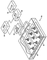
ここで図1を参照すると、該図は、本発明の一つの実施形態に従って乾燥させられている薬物パッチ20のアレイの模式図である。該薬物パッチは、面22の上に並べられ、該面は、乾燥チャンバー(drying chamber)24の内部に配置され、かつ、乾燥させる間、静止したままである。いくつかの実施形態では、乾燥チャンバーの開口部は、乾燥させる間、カバー26で覆われる。圧力源28は、開口部30のアレイからガスを送り出し(pump out)、該開口部は、ガスの流れをパッチの方へと向かわせるように構成され、その流れの中心線は、前記面の法線から20度未満の角度にある。(図1に示す角度は、法線から実質的に0度である。)典型的には、該ガスは、空気および/または不活性ガスを含む。いくつかの実施形態では、各開口部は、図1に示すように、各々のパッチにガスを向かわせる。
Detailed Description of the Embodiments Reference is now made to FIG. 1, which is a schematic illustration of an array of
いくつかの実施形態では、パッチを乾燥させるガスの湿度(humidity)が制御される。典型的には、ガスは、図1に示すように、湿度コントローラー36を通過する。典型的には、該湿度コントローラーは、ガスの湿度を、2%から20%の相対湿度に維持するように構成される。いくつかの実施形態では、該コントローラーは、該湿度を、5%から10%の相対湿度に維持する。いくつかの適用のためには、湿度検出器32が、ガスの湿度を検出するか、あるいは、パッチが乾燥させられる環境(例えば、パッチが乾燥させられる部屋または乾燥チャンバー)の湿度を検出する。制御ユニット34は、湿度コントローラーによって、検出された湿度に応じて、ガスの湿度を調節する。
In some embodiments, the humidity of the gas that dries the patch is controlled. Typically, the gas passes through a
各々の相対的な湿度レベルを持った制御された環境において乾燥させられた、パッチの溶出特性を評価した実験について、以下に説明する。より低い相対湿度の条件におけるパッチの乾燥は、顕著に優れた溶出特性を有するパッチをもたらすことを、本発明者らは観察した。本発明者らは引き続いて実験を行い、パッチを乾燥させるために使用されるガスの湿度を制御した。5%から10%の相対湿度を有するガスで乾燥させられたパッチは、良好な溶出特性を有することが観察された。 An experiment evaluating the elution characteristics of patches dried in a controlled environment with each relative humidity level is described below. We have observed that drying of patches at lower relative humidity conditions results in patches with significantly better elution properties. The inventors subsequently conducted experiments to control the humidity of the gas used to dry the patch. Patches dried with a gas having a relative humidity of 5% to 10% were observed to have good elution properties.
ここで図2を参照すると、該図は、本発明の一つの実施形態に従って乾燥させられている薬物パッチ20のアレイの模式図である。パッチの1列だけを示しているが、いくつかの実施形態では、該アレイは複数の列を有する。パッチは、面22上にアレイになるように並べられ、乾燥チャンバー内を移動するように構成される。例えば、面22は、コンベヤーベルトの表面を有し得る。乾燥させることに先立って、パッチは面上にアレイになるように並べられ、次いで、該面が乾燥チャンバー内を移動する。該面の移動方向を矢印50で示している。
Reference is now made to FIG. 2, which is a schematic illustration of an array of
いくつかの実施形態では、開口部は、図2に示すように、ノズルを規定するような形状である。典型的には、それらノズルは、空気圧式の調節可能バルブ(pneumatic adjustable valve)であり、例えば、Pisco Pneumatic Equipments LTDによって製造されている(モデル no. JNC4-01)。それらノズルは、パッチを乾燥させる間に、各々のパッチに向けてガスのジェット(jet、噴流)を方向付けるように構成される。いくつかの実施形態では、面22は、パッチを乾燥させる間は、静止したままである。代替的には、面22は、乾燥させる間にチャンバーを通過するように移動し、かつ、ジェットは、各パッチが各々のジェットと一線上にそろったときにのみ、パッチにガスを向かわせるように構成される。パッチは、乾燥後に、矢印50の方向に、乾燥チャンバーから出て行く。
In some embodiments, the opening is shaped to define a nozzle, as shown in FIG. Typically, these nozzles are pneumatic adjustable valves, for example, manufactured by Pisco Pneumatic Equipments LTD (model no. JNC4-01). The nozzles are configured to direct a jet of gas toward each patch while drying the patch. In some embodiments, the
ここで図3を参照すると、該図は、本発明の一つの実施形態に従って乾燥させられている薬物パッチ20のアレイの模式図である。該パッチは、面22の上に並べられ、該面は、パッチを乾燥させる間に、矢印50の方向へ移動する。パッチの1列だけを示しているが、いくつかの実施形態では、該アレイは複数の列を有する。乾燥チャンバー24の内側の上面は、開口部(openings、複数の開口)30を規定する形状になっており、それら開口部は、乾燥チャンバー内におよびパッチに対して各々のガスの流れを向かわせ、各々のガス流の中心線は、該面の法線から20度未満の角度にある。典型的には、ガスは、3m/sから15m/s(例えば、6m/sから12m/s)の速度でパッチに向かわせられる。開口部は、パッチの方向にガスを向かわせるが、個々のパッチに向かわせるのではない。その実施形態では、隣り合ったノズルから出てくるガスの流れが重なり合っている。典型的には、ジェットの各々の中心線52からの広がりアルファは、10度から30度(例えば、15度から25度)である。開口部30は、典型的には、0.5mmから7mm(例えば、2mmから5mm)の直径を有する。開口部からパッチまでの距離D1は、典型的には、0.5cmから7cm(例えば、2cmから5cm)である。
Reference is now made to FIG. 3, which is a schematic illustration of an array of
いくつかの実施形態では、パッチは、面22の上に並べられ、かつ、面22は、連続式の組立てライン状の様式で乾燥チャンバーを通るように移動する。制御ユニット34は、該面の移動、および、開口部を通したガスの方向付けを制御するように構成される。いくつかの適用のためには、制御ユニットは、湿度検出器32によって検出された湿度に応じて、面の移動またはガスの方向付けを制御するように構成される。
In some embodiments, the patches are arranged on the
最終的な溶出特性に対する、薬物パッチが乾燥させられる環境の湿度の影響を調べるための実験を行った。10mg/mLのhPTH溶液を各パッチに塗布することにより、50マイクログラムのhPTH(1−34)(ヒト副甲状腺ホルモン)がパッチにプリントされた。パッチを、25Cで3時間、2つの相対的な湿度レベルの下で気候(climatic)チャンバー内で乾燥させた:
1. 5個のパッチを、84%の相対湿度に制御された条件において乾燥させた。
2. 5個のパッチを、45%の相対湿度に制御された条件において乾燥させた。
An experiment was conducted to investigate the effect of the humidity of the environment in which the drug patch was dried on the final dissolution characteristics. 50 micrograms of hPTH (1-34) (human parathyroid hormone) was printed on the patches by applying a 10 mg / mL hPTH solution to each patch. The patch was dried in a climatic chamber under two relative humidity levels for 3 hours at 25C:
1. Five patches were dried at controlled conditions of 84% relative humidity.
2. Five patches were dried in conditions controlled at 45% relative humidity.
気候チャンバー内での3時間の乾燥後に、アルゴンガスで満たされかつシリカゲル小袋が収容された袋にパッチを詰め、4Cに保持された部屋に移した。 After drying for 3 hours in the climatic chamber, the pouch was packed into a bag filled with argon gas and containing a silica gel sachet and transferred to a room held at 4C.
5個のパッチの第3のグループを、約1.5%の相対湿度の条件下、25Cで乾燥させた。この条件は、パッチの塗り付けの直後に、シリカゲルを有する密封ラミネートされた袋内にパッチを入れることによって作り出した。 A third group of 5 patches was dried at 25C under conditions of about 1.5% relative humidity. This condition was created by placing the patch in a sealed laminated bag with silica gel immediately after applying the patch.
パッチの溶出特性を、3日後および7日後に、トリフルオロ酢酸/高速液体クロマトグラフィー(TFA−HPLC)分析を用いて分析した。結果を表1に示す。 The elution characteristics of the patches were analyzed after 3 and 7 days using trifluoroacetic acid / high performance liquid chromatography (TFA-HPLC) analysis. The results are shown in Table 1.

この結果は、より低い相対湿度の条件においてパッチを乾燥させることで、改善された溶出特性を有するパッチがもたらされることを示している。 This result shows that drying the patch at conditions of lower relative humidity results in a patch with improved elution characteristics.
さらなる実験を行い、90マイクログラムのhPTH(1−34)を24個のパッチの一群に塗り付けた。30%RH/25Cから45%RH/25Cの制御された湿度を有する環境において、当該分野で公知の乾燥技術を用いてパッチを乾燥させた。パッチの乾燥時間を測定したところ、パッチは、30分から50分の乾燥時間であった。5個のパッチの溶出特性を、4Cの部屋内で1週間、シリカゲルの小袋を含有する袋中でパッチを保管した後に分析した。パッチは、最初に乾燥させられて各々のパッチ上にあるhPTH(1−34)の量の、平均85.1%±3.5%を放出した。前記パッチの一群の残りのパッチのうちの5つについて溶出特性を、当該残りのパッチを4Cの部屋内で1ヶ月間、シリカゲルの小袋を含有する袋中に保管した後で分析した。パッチは、最初に乾燥させられて各々のパッチ上にあったhPTH(1−34)の量の、平均83.0%±4.1%の量を放出した。 In further experiments, 90 micrograms of hPTH (1-34) was applied to a group of 24 patches. Patches were dried using drying techniques known in the art in an environment having a controlled humidity of 30% RH / 25C to 45% RH / 25C. When the drying time of the patch was measured, the patch had a drying time of 30 to 50 minutes. The elution characteristics of the five patches were analyzed after storing the patches in a bag containing a silica gel sachet for 1 week in a 4C room. The patches were first dried to release an average of 85.1% ± 3.5% of the amount of hPTH (1-34) on each patch. The dissolution characteristics of five of the remaining patches in the group of patches were analyzed after the remaining patches were stored in a bag containing silica gel sachets for 1 month in a 4C room. The patches released an average amount of 83.0% ± 4.1% of the amount of hPTH (1-34) that was initially dried and on each patch.
なおさらなる実験において、本発明者らは、上述したような法線流の乾燥技術を用いて乾燥させた50個のパッチを分析した。分析したパッチは、hPTH(1−34)のパッチであり、乾燥させられてパッチ上にあった薬物を、50マイクログラムまたは80マイクログラム有している。該パッチは、5%RH/25Cから10%RH/25Cの相対湿度を有する乾燥空気で乾燥させたものである。これらの条件下でのパッチの平均乾燥時間は、4分未満であった。全てのパッチは、最初に乾燥させられて各々のパッチ上にあったhPTH(1−34)の量の、80%から90%を放出した。加えて、該パッチは、他の実験に関して上述した代替的な方法によって乾燥されたパッチと同様、5%未満の分解産物を放出した。これらの結果は、法線流の乾燥を使用し、かつ乾燥空気を使用するパッチの乾燥により、好適な溶出特性を有するパッチが、比較的短時間で生成されることを本発明者らに示した。 In a still further experiment, we analyzed 50 patches dried using the normal flow drying technique as described above. The analyzed patch is a patch of hPTH (1-34) and has 50 or 80 micrograms of drug that was dried and on the patch. The patch was dried with dry air having a relative humidity of 5% RH / 25C to 10% RH / 25C. The average drying time of the patch under these conditions was less than 4 minutes. All patches released 80% to 90% of the amount of hPTH (1-34) originally dried and on each patch. In addition, the patch released less than 5% degradation products, similar to patches dried by the alternative methods described above for other experiments. These results indicate to the inventors that patches with suitable elution characteristics are produced in a relatively short time using normal flow drying and drying of the patches using dry air. It was.
本発明の一つの実施形態では、1列のパッチが、薬物パッチ製造ラインの部分として連続的に稼動するコンベヤーベルトに乗って、乾燥チャンバーを通過する。5%RH/25Cから10%RH/25Cの湿度を有する乾燥空気が、法線流にてコンベヤーベルトに向けられる。これらの条件下で、各パッチは約4分間乾燥させられる(実際の時間は多くの要因に依存する)。一つの実施形態では、コンベヤーベルトは1m/分の速度で移動し、かつ、コンベヤーベルトの長さは4メートルである。直径が2cmである円形パッチまたは一辺が2cmである正方形パッチが、コンベヤーベルトの1メートル毎に50個のパッチが並ぶように、コンベヤーベルト上に並べられる。1分毎に、コンベヤーベルト上で乾燥させられた50個の乾燥パッチが、製造ラインの次の段階に移動する。いくつかの実施形態では、1列を超えるパッチが、コンベヤーベルト上に並べられ、例えば、4列のパッチをコンベヤーベルト上に隣接して並べてもよく、それにより、1分あたり200個のパッチが乾燥させられる。 In one embodiment of the invention, a single row of patches passes through a drying chamber on a conveyor belt that runs continuously as part of a drug patch production line. Dry air having a humidity of 5% RH / 25C to 10% RH / 25C is directed to the conveyor belt in a normal flow. Under these conditions, each patch is allowed to dry for about 4 minutes (the actual time depends on many factors). In one embodiment, the conveyor belt moves at a speed of 1 m / min and the length of the conveyor belt is 4 meters. Circular patches with a diameter of 2 cm or square patches with a side of 2 cm are arranged on the conveyor belt so that 50 patches are arranged per meter of the conveyor belt. Every minute, 50 dry patches dried on the conveyor belt move to the next stage of the production line. In some embodiments, more than one row of patches are arranged on a conveyor belt, for example, four rows of patches may be arranged adjacent to each other on the conveyor belt, thereby providing 200 patches per minute. Dried.
本発明は、上記に特に示して説明したものに限定されないことが当業者に理解されるであろう。むしろ、本発明の範囲には、上述した様々な特徴の組み合わせおよび部分的組み合わせの両方、ならびに先行技術にはなく、上記記載を読んだ当業者が想起するであろうそれらの変形および改良が含まれる。 It will be appreciated by persons skilled in the art that the present invention is not limited to what has been particularly shown and described hereinabove. Rather, the scope of the present invention includes both the various feature combinations and subcombinations described above, as well as variations and modifications thereof that would occur to those of ordinary skill in the art upon reading the above description, not in the prior art. It is.
Claims (18)
面を有し、該面は、1つ以上の薬物パッチを保持するように構成され、
乾燥チャンバーを有し、該乾燥チャンバーは、ガス流入用開口部のアレイを定める形状となっており、該ガス流入用開口部のアレイは、該薬物パッチの乾燥を促進するように構成され、かつ、該ガス流入用開口部は、ガスの流れを該薬物パッチに向かわせることによって、該薬物パッチを乾燥させるものであり、前記流れの中心線は、前記面の法線から20度未満の角度にあり、
前記1つ以上の薬物パッチを保持するように構成された前記面が、該薬物パッチを乾燥させる間は、静止するように構成されている、
前記装置。 A device, the device comprising :
Having a surface, said surface is configured to hold one or more drug patches,
Has a drying chamber, said drying chamber has a shape defining an array of gas inlet openings, the array of the gas inlet opening is configured to facilitate drying of the drug patch, and the gas inlet openings, by directing a flow of gas into the drug patch is intended for drying the drug patch, a center line of the flow of less than 20 degrees from the normal of the surface angle near is,
The surface configured to hold the one or more drug patches is configured to remain stationary while the drug patch is dried;
Said device.
Applications Claiming Priority (3)
| Application Number | Priority Date | Filing Date | Title |
|---|---|---|---|
| US101607P | 2007-10-29 | 2007-10-29 | |
| US61/001,016 | 2007-10-29 | ||
| PCT/IL2008/001427 WO2009057112A2 (en) | 2007-10-29 | 2008-10-29 | Vertical patch drying |
Publications (2)
| Publication Number | Publication Date |
|---|---|
| JP2011500259A JP2011500259A (en) | 2011-01-06 |
| JP5508272B2 true JP5508272B2 (en) | 2014-05-28 |
Family
ID=40591590
Family Applications (1)
| Application Number | Title | Priority Date | Filing Date |
|---|---|---|---|
| JP2010530631A Expired - Fee Related JP5508272B2 (en) | 2007-10-29 | 2008-10-29 | Vertical patch drying |
Country Status (5)
| Country | Link |
|---|---|
| US (1) | US20100293807A1 (en) |
| EP (1) | EP2211918B1 (en) |
| JP (1) | JP5508272B2 (en) |
| CA (1) | CA2704164A1 (en) |
| WO (1) | WO2009057112A2 (en) |
Cited By (1)
| Publication number | Priority date | Publication date | Assignee | Title |
|---|---|---|---|---|
| US10322296B2 (en) | 2009-07-20 | 2019-06-18 | Syneron Medical Ltd. | Method and apparatus for fractional skin treatment |
Families Citing this family (10)
| Publication number | Priority date | Publication date | Assignee | Title |
|---|---|---|---|---|
| WO2003089043A2 (en) | 2002-04-19 | 2003-10-30 | Transpharma Medical Ltd. | Handheld transdermal drug delivery and analyte extraction |
| JP2008543359A (en) * | 2005-06-10 | 2008-12-04 | トランスファーマ メディカル,リミティド | Patch for transdermal medication |
| CA2704740C (en) * | 2007-10-09 | 2016-05-17 | Transpharma Ltd. | Magnetic patch coupling |
| CA2696227A1 (en) * | 2007-10-17 | 2009-04-23 | Transpharma Medical Ltd. | Dissolution rate verification |
| JP2011505899A (en) | 2007-12-05 | 2011-03-03 | シネロン メディカル リミテッド | Disposable electromagnetic energy applicator and method of using the same |
| US8606366B2 (en) | 2009-02-18 | 2013-12-10 | Syneron Medical Ltd. | Skin treatment apparatus for personal use and method for using same |
| TW201321081A (en) * | 2011-11-21 | 2013-06-01 | 鴻海精密工業股份有限公司 | Blowing structure |
| WO2014192887A1 (en) * | 2013-05-29 | 2014-12-04 | 久光製薬株式会社 | System for producing microneedle pharmaceutical preparation, and air-conditioning method |
| WO2014192890A1 (en) * | 2013-05-29 | 2014-12-04 | 久光製薬株式会社 | System for manufacturing microneedle preparation, and air-conditioning method |
| CN112880369A (en) * | 2021-01-28 | 2021-06-01 | 西安奕斯伟硅片技术有限公司 | Device and method for controlling TDH (time domain reflectometry) of silicon wafer |
Family Cites Families (92)
| Publication number | Priority date | Publication date | Assignee | Title |
|---|---|---|---|---|
| US3163166A (en) * | 1961-04-28 | 1964-12-29 | Colgate Palmolive Co | Iontophoresis apparatus |
| GB1159711A (en) * | 1966-05-27 | 1969-07-30 | Victoria Heating & Ventilating | Improvements relating to Apparatus for Drying Ceramic Ware. |
| US4287671A (en) | 1978-09-15 | 1981-09-08 | George Koch Sons, Inc. | Method of curing coated articles |
| DE2928201A1 (en) * | 1979-07-12 | 1981-01-29 | Remonato | Continuous drying appts. partic. for tanned hides - with air flow between adjacent stages controlled by dampers |
| US4365423A (en) * | 1981-03-27 | 1982-12-28 | Eastman Kodak Company | Method and apparatus for drying coated sheet material |
| DE3433224A1 (en) * | 1984-09-10 | 1986-03-20 | Lohmann Gmbh & Co Kg, 5450 Neuwied | DRYING DEVICE FOR RAIL-SHAPED MATERIALS |
| EP0249343B1 (en) | 1986-06-13 | 1992-01-08 | Alza Corporation | Moisture activation of transdermal drug delivery system |
| US4837027A (en) * | 1987-11-09 | 1989-06-06 | Alza Corporation | Transdermal drug delivery device |
| US4915950A (en) * | 1988-02-12 | 1990-04-10 | Cygnus Research Corporation | Printed transdermal drug delivery device |
| US5008110A (en) * | 1988-11-10 | 1991-04-16 | The Procter & Gamble Company | Storage-stable transdermal patch |
| DE3910543A1 (en) * | 1989-04-01 | 1990-10-11 | Lohmann Therapie Syst Lts | TRANSDERMAL THERAPEUTIC SYSTEM WITH INCREASED ACTIVE FLUID AND METHOD FOR THE PRODUCTION THEREOF |
| DE4014913C2 (en) * | 1990-05-10 | 1996-05-15 | Lohmann Therapie Syst Lts | Miniaturized transdermal therapeutic system for iontophoresis |
| US5833665A (en) * | 1990-06-14 | 1998-11-10 | Integra Lifesciences I, Ltd. | Polyurethane-biopolymer composite |
| US5318780A (en) * | 1991-10-30 | 1994-06-07 | Mediventures Inc. | Medical uses of in situ formed gels |
| US5681282A (en) * | 1992-01-07 | 1997-10-28 | Arthrocare Corporation | Methods and apparatus for ablation of luminal tissues |
| IL105529A0 (en) * | 1992-05-01 | 1993-08-18 | Amgen Inc | Collagen-containing sponges as drug delivery for proteins |
| US5318514A (en) * | 1992-08-17 | 1994-06-07 | Btx, Inc. | Applicator for the electroporation of drugs and genes into surface cells |
| US6315772B1 (en) | 1993-09-24 | 2001-11-13 | Transmedica International, Inc. | Laser assisted pharmaceutical delivery and fluid removal |
| US5380272A (en) * | 1993-01-28 | 1995-01-10 | Scientific Innovations Ltd. | Transcutaneous drug delivery applicator |
| KR100355857B1 (en) * | 1993-03-22 | 2003-03-31 | 미네소타 마이닝 앤드 매뉴팩춰링 캄파니 | Adhesive composite dressing and manufacturing method |
| US5445609A (en) * | 1993-05-28 | 1995-08-29 | Alza Corporation | Electrotransport agent delivery device having a disposable component and a removable liner |
| FR2709670B1 (en) * | 1993-09-10 | 1995-10-20 | Asulab Sa | Device in three modules for transdermal administration of drugs by electrophoresis or iontophoresis. |
| US5458140A (en) * | 1993-11-15 | 1995-10-17 | Non-Invasive Monitoring Company (Nimco) | Enhancement of transdermal monitoring applications with ultrasound and chemical enhancers |
| US5445611A (en) * | 1993-12-08 | 1995-08-29 | Non-Invasive Monitoring Company (Nimco) | Enhancement of transdermal delivery with ultrasound and chemical enhancers |
| US5885211A (en) * | 1993-11-15 | 1999-03-23 | Spectrix, Inc. | Microporation of human skin for monitoring the concentration of an analyte |
| US20020169394A1 (en) * | 1993-11-15 | 2002-11-14 | Eppstein Jonathan A. | Integrated tissue poration, fluid harvesting and analysis device, and method therefor |
| US5466465A (en) * | 1993-12-30 | 1995-11-14 | Harrogate Holdings, Limited | Transdermal drug delivery system |
| US5681568A (en) * | 1994-08-19 | 1997-10-28 | Cambridge Neuroscience, Inc. | Device for delivery of substances and methods of use thereof |
| US5837281A (en) * | 1995-03-17 | 1998-11-17 | Takeda Chemical Industries, Ltd. | Stabilized interface for iontophoresis |
| EP0747092B1 (en) * | 1995-06-09 | 2003-12-03 | Hisamitsu Pharmaceutical Co., Inc. | Matrix for iontophoresis |
| US5906830A (en) * | 1995-09-08 | 1999-05-25 | Cygnus, Inc. | Supersaturated transdermal drug delivery systems, and methods for manufacturing the same |
| US6447800B2 (en) * | 1996-01-18 | 2002-09-10 | The University Of British Columbia | Method of loading preformed liposomes using ethanol |
| US5908401A (en) * | 1996-05-08 | 1999-06-01 | The Aps Organization, Llp | Method for iontophoretic delivery of antiviral agents |
| AU3880697A (en) * | 1996-07-03 | 1998-01-21 | Altea Technologies, Inc. | Multiple mechanical microporation of skin or mucosa |
| US5919156A (en) * | 1996-09-27 | 1999-07-06 | Becton, Dickinson And Company | Iontophoretic drug delivery system, including unit for dispensing patches |
| DE19644717A1 (en) * | 1996-10-28 | 1998-04-30 | Schlierbach Gmbh | Process for drying thin layers and device for carrying out the process |
| US6527716B1 (en) * | 1997-12-30 | 2003-03-04 | Altea Technologies, Inc. | Microporation of tissue for delivery of bioactive agents |
| US6374136B1 (en) | 1997-12-22 | 2002-04-16 | Alza Corporation | Anhydrous drug reservoir for electrolytic transdermal delivery device |
| ATE308924T1 (en) * | 1998-02-17 | 2005-11-15 | Abbott Lab | DEVICE FOR SAMPLING AND ANALYZING INTERSTITIAL FLUID |
| US6022316A (en) * | 1998-03-06 | 2000-02-08 | Spectrx, Inc. | Apparatus and method for electroporation of microporated tissue for enhancing flux rates for monitoring and delivery applications |
| US6530915B1 (en) * | 1998-03-06 | 2003-03-11 | Spectrx, Inc. | Photothermal structure for biomedical applications, and method therefor |
| US6173202B1 (en) * | 1998-03-06 | 2001-01-09 | Spectrx, Inc. | Method and apparatus for enhancing flux rates of a fluid in a microporated biological tissue |
| CN1255603C (en) * | 1998-07-01 | 2006-05-10 | 佐治亚科技研究公司 | Method for removing water from fibre fabric by adopting vibration reflux to impact air |
| DE69939906D1 (en) * | 1998-07-14 | 2008-12-24 | Altea Therapeutics Corp | TRANSDERMAL TRANSPORT DEVICE FOR THE CONTROLLED REMOVAL OF BIOLOGICAL MEMBRANES BY PYROTECHNICAL LOADING |
| US6597946B2 (en) * | 1998-11-09 | 2003-07-22 | Transpharma Ltd. | Electronic card for transdermal drug delivery and analyte extraction |
| US6708060B1 (en) * | 1998-11-09 | 2004-03-16 | Transpharma Ltd. | Handheld apparatus and method for transdermal drug delivery and analyte extraction |
| US6611706B2 (en) * | 1998-11-09 | 2003-08-26 | Transpharma Ltd. | Monopolar and bipolar current application for transdermal drug delivery and analyte extraction |
| US6148232A (en) * | 1998-11-09 | 2000-11-14 | Elecsys Ltd. | Transdermal drug delivery and analyte extraction |
| US5983135A (en) * | 1998-12-24 | 1999-11-09 | Avrahami; Zohar | Transdermal delivery of fine powders |
| US6713291B2 (en) * | 1999-01-28 | 2004-03-30 | Alan D. King | Electrodes coated with treating agent and uses thereof |
| ATE256484T1 (en) * | 1999-01-28 | 2004-01-15 | Cyto Pulse Sciences Inc | INTRODUCTION OF MACROMOLECULES INTO CELLS |
| DE19913761B4 (en) * | 1999-03-26 | 2005-02-10 | Lts Lohmann Therapie-Systeme Ag | Drying apparatus and method for its production and its use |
| WO2000061184A2 (en) * | 1999-04-08 | 2000-10-19 | Glenn Gregory M | Dry formulation for transcutaneous immunization |
| US6395300B1 (en) | 1999-05-27 | 2002-05-28 | Acusphere, Inc. | Porous drug matrices and methods of manufacture thereof |
| US6611707B1 (en) * | 1999-06-04 | 2003-08-26 | Georgia Tech Research Corporation | Microneedle drug delivery device |
| CA2376368C (en) * | 1999-06-08 | 2009-08-11 | Altea Technologies, Inc. | Apparatus for microporation of biological membranes using thin film tissue interface devices, and method therefor |
| US20030078499A1 (en) * | 1999-08-12 | 2003-04-24 | Eppstein Jonathan A. | Microporation of tissue for delivery of bioactive agents |
| US7133717B2 (en) * | 1999-08-25 | 2006-11-07 | Johnson & Johnson Consumer Companies, Inc. | Tissue electroperforation for enhanced drug delivery and diagnostic sampling |
| US6161304A (en) * | 1999-10-05 | 2000-12-19 | M&R Printing Equipment, Inc. | Dryer assembly |
| WO2001035820A1 (en) * | 1999-11-19 | 2001-05-25 | Spectrx, Inc. | Tissue interface device |
| US6565879B1 (en) * | 1999-12-16 | 2003-05-20 | Dermatrends, Inc. | Topical and transdermal administration of peptidyl drugs with hydroxide-releasing agents as skin permeation enhancers |
| US6522918B1 (en) | 2000-02-09 | 2003-02-18 | William E. Crisp | Electrolytic device |
| US6673386B2 (en) * | 2000-06-29 | 2004-01-06 | Matsushita Electric Industrial Co., Ltd. | Method and apparatus for forming pattern onto panel substrate |
| ATE324563T1 (en) * | 2000-09-24 | 2006-05-15 | 3M Innovative Properties Co | DRYING PROCESS FOR SELECTIVE REMOVAL OF VOLATILE COMPONENTS FROM WET COATINGS |
| KR20030068136A (en) * | 2000-10-13 | 2003-08-19 | 알자 코포레이션 | Apparatus and method for piercing skin with microprotrusions |
| US6855372B2 (en) * | 2001-03-16 | 2005-02-15 | Alza Corporation | Method and apparatus for coating skin piercing microprojections |
| AU2002252378B2 (en) * | 2001-03-19 | 2007-10-18 | Intercell Usa, Inc. | Transcutaneous immunostimulation |
| US7643874B2 (en) * | 2001-10-24 | 2010-01-05 | Power Paper Ltd. | Dermal patch |
| US8116860B2 (en) * | 2002-03-11 | 2012-02-14 | Altea Therapeutics Corporation | Transdermal porator and patch system and method for using same |
| WO2003077970A2 (en) * | 2002-03-11 | 2003-09-25 | Altea Therapeutics Corporation | Transdermal integrated actuator device, methods of making and using same |
| WO2003089043A2 (en) * | 2002-04-19 | 2003-10-30 | Transpharma Medical Ltd. | Handheld transdermal drug delivery and analyte extraction |
| AU2003221770A1 (en) | 2002-04-29 | 2003-11-17 | Stephen T. Flock | Controlled release transdermal drug delivery |
| US7097850B2 (en) * | 2002-06-18 | 2006-08-29 | Surmodics, Inc. | Bioactive agent release coating and controlled humidity method |
| WO2004028379A1 (en) | 2002-09-25 | 2004-04-08 | Flock, Stephen, T. | Microsurgical tissue treatment system |
| IL152575A (en) * | 2002-10-31 | 2008-12-29 | Transpharma Medical Ltd | Transdermal delivery system for water insoluble drugs |
| IL152573A (en) * | 2002-10-31 | 2009-11-18 | Transpharma Medical Ltd | Transdermal delivery system for anti-emetic medication |
| IL152574A (en) * | 2002-10-31 | 2009-09-22 | Transpharma Medical Ltd | Transdermal delivery system for dried particulate or lyophilized medications |
| US7383084B2 (en) * | 2002-10-31 | 2008-06-03 | Transpharma Medical Ltd. | Transdermal delivery system for dried particulate or lyophilized medications |
| US20060002862A1 (en) * | 2002-12-17 | 2006-01-05 | Medimmune Vaccines, Inc. | High pressure spray-dry of bioactive materials |
| JP5015594B2 (en) * | 2003-06-23 | 2012-08-29 | トランスファーマ メディカル リミテッド | Transdermal delivery system for cosmetics |
| US7785653B2 (en) * | 2003-09-22 | 2010-08-31 | Innovational Holdings Llc | Method and apparatus for loading a beneficial agent into an expandable medical device |
| JP2007508914A (en) * | 2003-10-24 | 2007-04-12 | アルザ・コーポレーシヨン | Apparatus and method for facilitating transdermal drug delivery |
| CN1897920A (en) * | 2003-10-31 | 2007-01-17 | 阿尔扎公司 | Systems and methods for transdermal vaccine delivery |
| US20050208095A1 (en) * | 2003-11-20 | 2005-09-22 | Angiotech International Ag | Polymer compositions and methods for their use |
| AU2004314416A1 (en) * | 2004-01-09 | 2005-08-04 | Alza Corporation | Frequency assisted transdermal agent delivery method and system |
| IL160033A0 (en) * | 2004-01-25 | 2004-06-20 | Transpharma Medical Ltd | Transdermal delivery system for polynucleotides |
| WO2005088299A1 (en) | 2004-03-10 | 2005-09-22 | Hisamitsu Medical Co., Ltd. | Method of assaying dermal permeability of transdermal drug mediated by dermal transporter |
| CA2587780A1 (en) * | 2004-11-18 | 2006-05-26 | Transpharma Medical Ltd. | Combined micro-channel generation and iontophoresis for transdermal delivery of pharmaceutical agents |
| AU2006211176A1 (en) * | 2005-01-31 | 2006-08-10 | Alza Corporation | Coated microprojections having reduced variability and method for producing same |
| US20060222640A1 (en) * | 2005-03-29 | 2006-10-05 | Boehringer Ingelheim International Gmbh | New pharmaceutical compositions for treatment of thrombosis |
| JP2008543359A (en) * | 2005-06-10 | 2008-12-04 | トランスファーマ メディカル,リミティド | Patch for transdermal medication |
| TWI419717B (en) * | 2005-06-17 | 2013-12-21 | Altea Therapeutics Corp | Osmotic delivery system and method of use thereof |
-
2008
- 2008-10-29 JP JP2010530631A patent/JP5508272B2/en not_active Expired - Fee Related
- 2008-10-29 WO PCT/IL2008/001427 patent/WO2009057112A2/en not_active Ceased
- 2008-10-29 US US12/740,184 patent/US20100293807A1/en not_active Abandoned
- 2008-10-29 CA CA2704164A patent/CA2704164A1/en not_active Abandoned
- 2008-10-29 EP EP08845172.9A patent/EP2211918B1/en not_active Not-in-force
Cited By (1)
| Publication number | Priority date | Publication date | Assignee | Title |
|---|---|---|---|---|
| US10322296B2 (en) | 2009-07-20 | 2019-06-18 | Syneron Medical Ltd. | Method and apparatus for fractional skin treatment |
Also Published As
| Publication number | Publication date |
|---|---|
| WO2009057112A3 (en) | 2010-03-11 |
| EP2211918A2 (en) | 2010-08-04 |
| EP2211918A4 (en) | 2012-01-25 |
| EP2211918B1 (en) | 2017-10-18 |
| CA2704164A1 (en) | 2009-05-07 |
| US20100293807A1 (en) | 2010-11-25 |
| WO2009057112A2 (en) | 2009-05-07 |
| JP2011500259A (en) | 2011-01-06 |
Similar Documents
| Publication | Publication Date | Title |
|---|---|---|
| JP5508272B2 (en) | Vertical patch drying | |
| JP5687276B2 (en) | Pulsed release of drug from punctal plug | |
| AU2009208883B2 (en) | Method for making patches by electrospray | |
| ES2908339T3 (en) | Microarray for delivery of a therapeutic agent and methods of use | |
| CN102770176B (en) | Microneedle devices and manufacture method thereof | |
| EP3106197B1 (en) | Balloon coating method | |
| EP3106199B1 (en) | Balloon coating method, coat layer control method and balloon coating device | |
| JP5378465B2 (en) | Granule production method | |
| KR101866005B1 (en) | Microneedle-coating composition and microneedle device | |
| JP5837066B2 (en) | Device for transdermal drug delivery | |
| EP3106198B1 (en) | Positioning method for balloon coating | |
| EP3106196B1 (en) | Positioning method for balloon coating | |
| Vlachou et al. | Electrospinning and drug delivery | |
| KR100439156B1 (en) | Covering composition for drug releasing stent and method of preparing same | |
| Halim et al. | Electrospinning in drug delivery: progress and future outlook | |
| JP2006528604A5 (en) | ||
| WO2014192890A1 (en) | System for manufacturing microneedle preparation, and air-conditioning method | |
| CN109966564B (en) | Drug-loaded balloon and preparation method thereof | |
| KR20190085643A (en) | Manufacturing method for micro-structure | |
| TWI636781B (en) | Microneedle preparation system and air conditioning method | |
| US20180056053A1 (en) | Protruding microstructure for transdermal delivery | |
| Chandrasekar et al. | AN EXTENSIVE REVIEW ON MUCOADHESIVE MICROSPHERES AS CARRIERS IN DRUG DELIVERY | |
| JP2009514989A (en) | Modified release loxoprofen composition | |
| CN119033670A (en) | High drug-loading-capacity coating microneedle containing chitosan ascorbic acid derivative (CSVC) and preparation method thereof | |
| KR20170067637A (en) | Manufacturing method of microstructure |
Legal Events
| Date | Code | Title | Description |
|---|---|---|---|
| A621 | Written request for application examination |
Free format text: JAPANESE INTERMEDIATE CODE: A621 Effective date: 20111013 |
|
| A977 | Report on retrieval |
Free format text: JAPANESE INTERMEDIATE CODE: A971007 Effective date: 20130207 |
|
| A131 | Notification of reasons for refusal |
Free format text: JAPANESE INTERMEDIATE CODE: A131 Effective date: 20130219 |
|
| A601 | Written request for extension of time |
Free format text: JAPANESE INTERMEDIATE CODE: A601 Effective date: 20130517 |
|
| A602 | Written permission of extension of time |
Free format text: JAPANESE INTERMEDIATE CODE: A602 Effective date: 20130524 |
|
| A601 | Written request for extension of time |
Free format text: JAPANESE INTERMEDIATE CODE: A601 Effective date: 20130619 |
|
| A602 | Written permission of extension of time |
Free format text: JAPANESE INTERMEDIATE CODE: A602 Effective date: 20130626 |
|
| A601 | Written request for extension of time |
Free format text: JAPANESE INTERMEDIATE CODE: A601 Effective date: 20130719 |
|
| A602 | Written permission of extension of time |
Free format text: JAPANESE INTERMEDIATE CODE: A602 Effective date: 20130726 |
|
| A521 | Request for written amendment filed |
Free format text: JAPANESE INTERMEDIATE CODE: A523 Effective date: 20130819 |
|
| TRDD | Decision of grant or rejection written | ||
| A01 | Written decision to grant a patent or to grant a registration (utility model) |
Free format text: JAPANESE INTERMEDIATE CODE: A01 Effective date: 20140218 |
|
| A61 | First payment of annual fees (during grant procedure) |
Free format text: JAPANESE INTERMEDIATE CODE: A61 Effective date: 20140320 |
|
| R150 | Certificate of patent or registration of utility model |
Ref document number: 5508272 Country of ref document: JP Free format text: JAPANESE INTERMEDIATE CODE: R150 |
|
| R250 | Receipt of annual fees |
Free format text: JAPANESE INTERMEDIATE CODE: R250 |
|
| R250 | Receipt of annual fees |
Free format text: JAPANESE INTERMEDIATE CODE: R250 |
|
| LAPS | Cancellation because of no payment of annual fees |