JP5495357B2 - Image display method and medical image diagnostic system - Google Patents
Image display method and medical image diagnostic system Download PDFInfo
- Publication number
- JP5495357B2 JP5495357B2 JP2007539851A JP2007539851A JP5495357B2 JP 5495357 B2 JP5495357 B2 JP 5495357B2 JP 2007539851 A JP2007539851 A JP 2007539851A JP 2007539851 A JP2007539851 A JP 2007539851A JP 5495357 B2 JP5495357 B2 JP 5495357B2
- Authority
- JP
- Japan
- Prior art keywords
- image
- positional relationship
- cut surface
- dimensional image
- relationship display
- Prior art date
- Legal status (The legal status is an assumption and is not a legal conclusion. Google has not performed a legal analysis and makes no representation as to the accuracy of the status listed.)
- Active
Links
Images


Classifications
-
- A—HUMAN NECESSITIES
- A61—MEDICAL OR VETERINARY SCIENCE; HYGIENE
- A61B—DIAGNOSIS; SURGERY; IDENTIFICATION
- A61B8/00—Diagnosis using ultrasonic, sonic or infrasonic waves
- A61B8/48—Diagnostic techniques
- A61B8/483—Diagnostic techniques involving the acquisition of a 3D volume of data
-
- A—HUMAN NECESSITIES
- A61—MEDICAL OR VETERINARY SCIENCE; HYGIENE
- A61B—DIAGNOSIS; SURGERY; IDENTIFICATION
- A61B6/00—Apparatus or devices for radiation diagnosis; Apparatus or devices for radiation diagnosis combined with radiation therapy equipment
- A61B6/46—Arrangements for interfacing with the operator or the patient
- A61B6/461—Displaying means of special interest
- A61B6/466—Displaying means of special interest adapted to display 3D data
-
- A—HUMAN NECESSITIES
- A61—MEDICAL OR VETERINARY SCIENCE; HYGIENE
- A61B—DIAGNOSIS; SURGERY; IDENTIFICATION
- A61B8/00—Diagnosis using ultrasonic, sonic or infrasonic waves
- A61B8/13—Tomography
- A61B8/14—Echo-tomography
-
- A—HUMAN NECESSITIES
- A61—MEDICAL OR VETERINARY SCIENCE; HYGIENE
- A61B—DIAGNOSIS; SURGERY; IDENTIFICATION
- A61B8/00—Diagnosis using ultrasonic, sonic or infrasonic waves
- A61B8/52—Devices using data or image processing specially adapted for diagnosis using ultrasonic, sonic or infrasonic waves
- A61B8/5215—Devices using data or image processing specially adapted for diagnosis using ultrasonic, sonic or infrasonic waves involving processing of medical diagnostic data
- A61B8/523—Devices using data or image processing specially adapted for diagnosis using ultrasonic, sonic or infrasonic waves involving processing of medical diagnostic data for generating planar views from image data in a user selectable plane not corresponding to the acquisition plane
-
- G—PHYSICS
- G06—COMPUTING OR CALCULATING; COUNTING
- G06T—IMAGE DATA PROCESSING OR GENERATION, IN GENERAL
- G06T15/00—3D [Three Dimensional] image rendering
- G06T15/08—Volume rendering
-
- G—PHYSICS
- G06—COMPUTING OR CALCULATING; COUNTING
- G06T—IMAGE DATA PROCESSING OR GENERATION, IN GENERAL
- G06T19/00—Manipulating 3D models or images for computer graphics
-
- A—HUMAN NECESSITIES
- A61—MEDICAL OR VETERINARY SCIENCE; HYGIENE
- A61B—DIAGNOSIS; SURGERY; IDENTIFICATION
- A61B5/00—Measuring for diagnostic purposes; Identification of persons
- A61B5/05—Detecting, measuring or recording for diagnosis by means of electric currents or magnetic fields; Measuring using microwaves or radio waves
- A61B5/055—Detecting, measuring or recording for diagnosis by means of electric currents or magnetic fields; Measuring using microwaves or radio waves involving electronic [EMR] or nuclear [NMR] magnetic resonance, e.g. magnetic resonance imaging
-
- G—PHYSICS
- G01—MEASURING; TESTING
- G01S—RADIO DIRECTION-FINDING; RADIO NAVIGATION; DETERMINING DISTANCE OR VELOCITY BY USE OF RADIO WAVES; LOCATING OR PRESENCE-DETECTING BY USE OF THE REFLECTION OR RERADIATION OF RADIO WAVES; ANALOGOUS ARRANGEMENTS USING OTHER WAVES
- G01S15/00—Systems using the reflection or reradiation of acoustic waves, e.g. sonar systems
- G01S15/88—Sonar systems specially adapted for specific applications
- G01S15/89—Sonar systems specially adapted for specific applications for mapping or imaging
- G01S15/8906—Short-range imaging systems; Acoustic microscope systems using pulse-echo techniques
- G01S15/8993—Three dimensional imaging systems
-
- G—PHYSICS
- G01—MEASURING; TESTING
- G01S—RADIO DIRECTION-FINDING; RADIO NAVIGATION; DETERMINING DISTANCE OR VELOCITY BY USE OF RADIO WAVES; LOCATING OR PRESENCE-DETECTING BY USE OF THE REFLECTION OR RERADIATION OF RADIO WAVES; ANALOGOUS ARRANGEMENTS USING OTHER WAVES
- G01S7/00—Details of systems according to groups G01S13/00, G01S15/00, G01S17/00
- G01S7/52—Details of systems according to groups G01S13/00, G01S15/00, G01S17/00 of systems according to group G01S15/00
- G01S7/52017—Details of systems according to groups G01S13/00, G01S15/00, G01S17/00 of systems according to group G01S15/00 particularly adapted to short-range imaging
- G01S7/52053—Display arrangements
- G01S7/52057—Cathode ray tube displays
- G01S7/52074—Composite displays, e.g. split-screen displays; Combination of multiple images or of images and alphanumeric tabular information
-
- G—PHYSICS
- G06—COMPUTING OR CALCULATING; COUNTING
- G06T—IMAGE DATA PROCESSING OR GENERATION, IN GENERAL
- G06T2219/00—Indexing scheme for manipulating 3D models or images for computer graphics
- G06T2219/008—Cut plane or projection plane definition
Landscapes
- Health & Medical Sciences (AREA)
- Life Sciences & Earth Sciences (AREA)
- Engineering & Computer Science (AREA)
- Physics & Mathematics (AREA)
- Medical Informatics (AREA)
- General Health & Medical Sciences (AREA)
- Surgery (AREA)
- Pathology (AREA)
- Biomedical Technology (AREA)
- Heart & Thoracic Surgery (AREA)
- Nuclear Medicine, Radiotherapy & Molecular Imaging (AREA)
- Molecular Biology (AREA)
- Radiology & Medical Imaging (AREA)
- Animal Behavior & Ethology (AREA)
- Biophysics (AREA)
- Public Health (AREA)
- Veterinary Medicine (AREA)
- Theoretical Computer Science (AREA)
- Computer Graphics (AREA)
- General Physics & Mathematics (AREA)
- High Energy & Nuclear Physics (AREA)
- Computer Vision & Pattern Recognition (AREA)
- Computer Hardware Design (AREA)
- General Engineering & Computer Science (AREA)
- Software Systems (AREA)
- Optics & Photonics (AREA)
- Human Computer Interaction (AREA)
- Ultra Sonic Daignosis Equipment (AREA)
- Apparatus For Radiation Diagnosis (AREA)
- Magnetic Resonance Imaging Apparatus (AREA)
- Image Generation (AREA)
Description
本発明は、被検体から得た画像を三次元表示する画像表示方法及び医用画像診断システムに関する。本出願は、日本国特許法に基づく特許出願特願2005−295108号に基づくパリ優先権主張を伴う出願であり、特願2005−295108号の利益を享受するために参照による援用を受ける出願である。 The present invention relates to an image display method and a medical image diagnostic system that three-dimensionally display an image obtained from a subject. This application is a patent application claiming priority based on Japanese Patent Application No. 2005-295108 based on the Japanese Patent Law, and is an application that is incorporated by reference in order to enjoy the benefits of Japanese Patent Application No. 2005-295108. is there.
医用画像診断装置において三次元画像を表示する手法の一つとして、最大輝度投影(Maximum Intensity Projection: MIP)法がある。MIP法では、結果として得ようとする像(MIP像)を構成する画素のそれぞれに対応する視線を考え、対象物のボリュームデータにおいて該視線上に存在する画素の持つ輝度のうちの最大値をMIP像の対応画素の輝度値とすることより、対象物から得た画像データを三次元的に表示するMIP像を得る。 One technique for displaying a three-dimensional image in a medical image diagnostic apparatus is a maximum intensity projection (MIP) method. In the MIP method, the line of sight corresponding to each of the pixels constituting the image to be obtained (MIP image) is considered, and the maximum value of the luminances of the pixels existing on the line of sight in the volume data of the object is calculated. By setting the luminance value of the corresponding pixel of the MIP image, an MIP image that three-dimensionally displays image data obtained from the object is obtained.
MIP像は、視線方向の奥行き情報を失っているので、平面的な画像となっている。したがって、検者は、平面的に表示されたMIP像では血管の奥行き関係を把握することができないので、血管の奥行き関係を把握するために別の視線角度の可視化像を合わせて見る必要があり、効率及び操作性が悪い。そこで、三次元画像に奥行き情報を付加して表示することが考えられる。 Since the MIP image loses depth information in the line-of-sight direction, it is a planar image. Therefore, the examiner cannot grasp the depth relationship of the blood vessel with the planarly displayed MIP image. Therefore, in order to grasp the depth relationship of the blood vessel, the examiner needs to view a visualization image with another line-of-sight angle. The efficiency and operability are poor. Therefore, it is conceivable to display depth information added to a three-dimensional image.
例えば、特開2000−245487号公報に開示された技術では、ボリュームレンダリングによる三次元画像の投影画像とボリューム内に設定された断面位置のボクセル値を表示した断面の画像とを合成した画像が表示されるが、その具体的な合成方法については何らの開示も示唆もない。 For example, in the technique disclosed in Japanese Patent Laid-Open No. 2000-245487, an image obtained by combining a projected image of a three-dimensional image by volume rendering and a cross-sectional image displaying voxel values of cross-sectional positions set in the volume is displayed. However, there is no disclosure or suggestion about the specific synthesis method.
本発明の目的は、奥行き情報を付与した三次元画像を作成して表示することである。 An object of the present invention is to create and display a three-dimensional image with depth information.
上記課題を解決するために、本発明は、ボリュームデータに基づいて三次元画像を作成する三次元画像作成ステップと、前記三次元画像を任意の位置で切断する切断面を設定する切断面設定ステップと、前記三次元画像と前記切断面との相互位置関係を表す位置関係表示画像であって、前記三次元画像のうち前記切断面によって隠れる部分が前記位置関係表示画像において前記切断面越しに視認可能であるように前記切断面の前記位置関係表示画像における不透明度が調整される、前記位置関係表示画像を作成する位置関係表示画像作成ステップと、を含む画像表示方法に係る。 In order to solve the above problems, the present invention provides a three-dimensional image creation step for creating a three-dimensional image based on volume data, and a cutting plane setting step for setting a cutting plane for cutting the three-dimensional image at an arbitrary position. And a positional relationship display image representing a mutual positional relationship between the three-dimensional image and the cut surface, and a portion of the three-dimensional image hidden by the cut surface is visually recognized through the cut surface in the positional relationship display image. And a positional relationship display image creating step of creating the positional relationship display image, wherein the opacity of the cut surface in the positional relationship display image is adjusted so as to be possible.
好ましくは、前記位置関係表示画像作成ステップにおいて、前記三次元画像の視線上で最大輝度値を有するボクセルの座標値と前記切断面の投影面における座標値とに基づいて、前記三次元画像と前記切断面のどちらが視点に近いか判定され、前記切断面が前記三次元画像よりも前記視点に近いと判定された場合、前記三次元画像のうち前記切断面によって隠れる部分が前記位置関係表示画像において前記切断面越しに視認可能であるように、前記三次元画像及び前記切断面の前記位置関係表示画像における不透明度が調整され、前記三次元画像が前記切断面よりも前記視点に近いと判定された場合、前記切断面のうち前記三次元画像によって隠れる部分が前記位置関係表示画像において前記三次元画像越しに視認可能であるように、前記三次元画像及び前記切断面の前記位置関係表示画像における不透明度が調整される。 Preferably, in the positional relationship display image creation step, based on the coordinate value of the voxel having the maximum luminance value on the line of sight of the three-dimensional image and the coordinate value on the projection plane of the cut surface, the three-dimensional image and the It is determined which of the cut planes is closer to the viewpoint, and when it is determined that the cut plane is closer to the viewpoint than the three-dimensional image, a portion of the three-dimensional image hidden by the cut plane is included in the positional relationship display image. Opacity in the positional relationship display image of the three-dimensional image and the cut surface is adjusted so that the image can be viewed through the cut surface, and it is determined that the three-dimensional image is closer to the viewpoint than the cut surface. The portion of the cut surface hidden by the 3D image is visible through the 3D image in the positional relationship display image. Opacity in the original image and the positional relationship display image of the cutting plane is adjusted.
また好ましくは、前記画像表示方法は、前記ボリュームデータに基づいて被検体の体表画像を作成する体表画像作成ステップを更に含み、前記位置関係表示画像作成ステップにおいて、前記三次元画像と前記切断面と前記体表画像との相互位置関係を表すように前記位置関係表示画像が作成される。 Further preferably, the image display method further includes a body surface image creation step of creating a body surface image of a subject based on the volume data, and in the positional relationship display image creation step, the three-dimensional image and the cutting The positional relationship display image is created so as to represent the mutual positional relationship between the surface and the body surface image.
また、上記課題を解決するために、本発明は、被検体に関するボリュームデータを記憶するボリュームデータ記憶手段と、前記ボリュームデータに基づいて最大輝度投影法によって三次元画像を作成する三次元画像作成手段と、前記三次元画像を任意の位置で切断する切断面を設定する切断面設定手段と、前記三次元画像と前記切断面を合成することにより、前記三次元画像と前記切断面との前記最大輝度投影法における投影方向での相互位置関係を表す位置関係表示画像を作成する位置関係表示画像作成手段であって、前記三次元画像の視線上で最大輝度値を有するボクセルの座標値と前記切断面の投影面における座標値とに基づいて、前記三次元画像と前記切断面のどちらが視点に近いか判定し、前記切断面が前記三次元画像よりも前記視点に近いと判定された場合、前記三次元画像のうち前記切断面によって隠れる部分が前記位置関係表示画像において前記切断面越しに視認可能であるように、前記三次元画像及び前記切断面の前記位置関係表示画像における不透明度を調整し、前記三次元画像が前記切断面よりも前記視点に近いと判定された場合、前記切断面のうち前記三次元画像によって隠れる部分が前記位置関係表示画像において前記三次元画像越しに視認可能であるように、前記三次元画像及び前記切断面の前記位置関係表示画像における不透明度を調整する位置関係表示画像作成手段と、を備える医用画像診断システムに係る。 In order to solve the above problems, the present invention provides volume data storage means for storing volume data relating to a subject, and 3D image creation means for creating a 3D image by a maximum brightness projection method based on the volume data. Cutting plane setting means for setting a cutting plane for cutting the three-dimensional image at an arbitrary position; and combining the three-dimensional image and the cutting plane, the maximum of the three-dimensional image and the cutting plane. A positional relationship display image creating means for creating a positional relationship display image representing a mutual positional relationship in the projection direction in the luminance projection method , wherein the coordinate value of the voxel having the maximum luminance value on the line of sight of the three-dimensional image and the cutting Based on the coordinate value in the projection plane of the surface, it is determined which of the three-dimensional image and the cut surface is closer to the viewpoint, and the cut surface is more than the three-dimensional image. If it is determined that the closer to the point, the so partially hidden by the cutting plane of the three-dimensional image is visible on the cut surface over at the positional relationship display image, the said three-dimensional image and the cutting plane When the opacity in the positional relationship display image is adjusted and it is determined that the three-dimensional image is closer to the viewpoint than the cut surface, a portion of the cut surface hidden by the three-dimensional image is included in the positional relationship display image. The present invention relates to a medical image diagnostic system comprising: a positional relationship display image creating unit that adjusts opacity in the positional relationship display image of the three-dimensional image and the cut surface so as to be visible through the three-dimensional image .
好ましくは、前記医用画像診断システムは、前記被検体との間で超音波を送受する探触子と、前記探触子に駆動信号を供給すると共に、前記探触子から出力される受信信号を処理して受信データを出力する超音波送受信手段と、前記超音波送受信手段から出力された前記受信データに基づいて超音波画像を再構成する超音波画像作成手段と、前記位置関係表示画像及び前記超音波画像の少なくとも一方を表示する表示手段と、を更に備える。 Preferably, the medical diagnostic imaging system supplies a drive signal to the probe that transmits / receives ultrasonic waves to / from the subject, and a reception signal output from the probe. Ultrasonic transmission / reception means for processing and outputting reception data; ultrasonic image creation means for reconstructing an ultrasonic image based on the reception data output from the ultrasonic transmission / reception means; the positional relationship display image; and Display means for displaying at least one of the ultrasonic images.
更に好ましくは、前記医用画像診断システムは、前記ボリュームデータ及び前記探触子の前記位置情報に基づいて前記超音波画像と同一断面のリファレンス画像を作成するリファレンス画像作成手段を更に備え、前記表示手段は、前記リファレンス画像を表示する。 More preferably, the medical image diagnostic system further includes reference image creation means for creating a reference image having the same cross section as the ultrasound image based on the volume data and the position information of the probe, and the display means Displays the reference image.
本発明によれば、例えばMIP画像を含む三次元画像において、奥行きを表現することができる。 According to the present invention, for example, depth can be expressed in a three-dimensional image including an MIP image.
10…医用画像診断装置、11…ボリュームデータ記憶部、12…MIP画像作成部、13…切断面作成部、14…位置関係表示画像作成部、15…表示部、16…制御部、17…操作部、21…視点、22…視線、23…ボリュームデータ、24…投影面、25…ボクセルデータのデータ列、26…最大輝度値のボクセル、27…投影面上の画素、31…血管のMIP像、32…血管のMIP像、33…血管のMIP像、34…切断面、35…MIP画像、36…被検体の体表を表すSR画像、50…超音波探触子、51…超音波送受信部、52…超音波画像作成部、53…磁気センサ、54…超音波断層面座標算出部、55…リファレンス画像作成部、56…表示部、57…超音波診断装置、58…三次元画像作成部、59…位置データ算出部、60…位置関係表示画像、61…超音波画像の表示エリア、62…リファレンス画像の表示エリア、63…超音波画像、64…リファレンス画像、65…血管の断面像、66…血管の断面像、67…血管の断面像、D…超音波画像の深度、F…超音波画像の視野、PR…プローブ半径
DESCRIPTION OF
本発明の第1の実施形態を、図1〜5を用いて説明する。図1は、第1の実施形態の医用画像診断システムのシステム構成図である。この医用画像診断システムは、被検体から三次元ボリュームデータを取得する医用画像診断装置10と、医用画像診断装置10が取得したボリュームデータを記憶するボリュームデータ記憶部11と、ボリュームデータ記憶部11が記憶したボリュームデータに基づいてMIP画像を作成するMIP画像作成部12と、三次元空間の切断面を作成する切断面作成部13と、MIP画像と切断面との相互位置関係を表す位置関係表示画像を作成する位置関係表示画像作成部14と、位置関係表示画像作成部14が作成した位置関係表示画像を表示する表示部15と、CPU(Central Processing Unit)からなり上記各構成要素の制御を行う制御部16と、マウス、トラックボール、キーボード等からなり、検者の指示を制御部16に与える操作部17と、を含む。
A first embodiment of the present invention will be described with reference to FIGS. FIG. 1 is a system configuration diagram of the medical image diagnostic system according to the first embodiment. The medical image diagnostic system includes a medical image
医用画像診断装置10は、例えば、CT(Computed Tomography)画像診断装置、MR(Magnetic Resonance)画像診断装置、超音波画像診断装置等のいずれかであり、被検体の三次元ボリュームデータを取得する画像診断装置である。例えば、CT画像診断装置で取得されるボリュームデータは、そのボリュームに対応する被検体の或る箇所のX線吸収値に基づいて算出されるCT値から得られるデータであり、MR画像診断装置で取得されるボリュームデータは、そのボリュームに対応する被検体の或る箇所のプロトン密度等の測定値から得られるデータである。
The medical image
ボリュームデータ記憶部11は、医用画像診断装置10が取得したボリュームデータをその三次元位置座標とともにメモリなどに記憶するものであり、様々な画像診断装置が取得した複数種類のボリュームデータを記憶することもできる。
The volume
MIP画像作成部12は、ボリュームデータ記憶部11に記憶されたボリュームデータに基づいてMIP法を用いてMIP画像を作成する。MIP法では、ボリュームデータに対し、検者が指定した視点及び投影面に対応した配置関係で二次元構造体である投影面を三次元空間に配置する。そして、ボリュームデータの投影面上の各画素への投影値として、投影線上にあるデータのうち値が最も大きなデータの値を求める。このようにして求めた投影値を各画素の値として、これら複数の画素に基づいてMIP画像を表示する。
The MIP
このMIP法について、図2を用いて具体的に説明する。ボリュームデータ記憶部11に、ボリュームデータ23がその三次元座標とともに記憶されている。検者の視点21からボリュームデータ23を貫通して投影面24上の画素27(座標(X,Y))に至る視線22を考え、視線22上のボリュームデータ列25のうち最大輝度を持つボクセル26の輝度を表示部15に表示される投影面24上の画素27の輝度とする。なお、ここでは説明のため、投影面24をXY面として表現し、視線方向をZ軸方向として表現する。
The MIP method will be specifically described with reference to FIG.
検者の視点21からの視線22はボリュームデータ23を貫通するものであり、視線22と投影面24とは位置(X,Y)で交わる。視線22上のボリュームデータ23は、0番目〜Zmax番目までのボクセルデータのデータ列25である。視線22上のデータ列25について、視点21側から輝度値の比較を行う。具体的には、0番目のボクセルデータの輝度値とそれと隣接する1番目のボクセルデータの輝度値との比較を行い、高い方の輝度値を最大輝度値とする。そして、求められた最大輝度値と2番目のボクセルデータの輝度値との比較を行い、高い方の輝度値を最大輝度値とする。この比較操作を、Zmax番目まで繰り返す。
The line of
例えば、n番目のボクセルデータの輝度値を輝度値Bn(nは0≦n≦Zmax−1の整数)として一般式で表現すると、Bn≧B(n+1)ならばBnを最大輝度値とし、Bn<B(n+1)ならばB(n+1)を新たな最大輝度値とする。そして、n=0からn=Zmax−1まで輝度値の比較操作を行って求められる最大輝度値を、投影面24の画素27の輝度値とする。例えばZ番目のボクセル26の輝度値が最大輝度値の場合、ボクセル26の輝度値を投影面24の位置(X,Y)の輝度値とする。MIP画像作成部12は、このようにして、位置(X,Y)に対応する最大輝度値を投影面24全体において求め、各点の最大輝度値で構成されるようなMIP画像を作成する。For example, when n-th (the n 0 ≦ n ≦ Zmax-1 integer) luminance value B n the luminance value of the voxel data is expressed by the general formula as, B n ≧ B (n + 1) if the maximum luminance value B n If B n <B (n + 1) , B (n + 1) is set as the new maximum luminance value. Then, the maximum luminance value obtained by performing the luminance value comparison operation from n = 0 to n = Zmax−1 is set as the luminance value of the
切断面作成部13は、投影面をXY平面とし視線方向をZ軸とするXYZ三次元空間における切断面を作成する。例えば、切断面が点(X0,Y0,Z0)を通り、切断面の回転成分RがThe cut
であるとき、切断面座標系上の点(X2D,Y2D)の三次元空間内における座標(X,Y,Z)は、, The coordinates (X, Y, Z) in the three-dimensional space of the point (X 2D , Y 2D ) on the cut plane coordinate system are
となる。 It becomes.
検者は、操作部17を介して、切断面の三次元空間内における位置及び角度を変えることができる。例えば、検者は、表示部15の画面上に表示されている切断面の中央部をマウスでクリックして切断面を指定し、トラックボールを操作することにより、(X0,Y0,Z0)を変化させて切断面の三次元位置を移動させる。また、検者は、表示部15の画面上に表示されている切断面の端部をマウスでクリックして切断面を指定し、トラックボールを操作することにより、回転成分Rを変化させて切断面を切断面の中心を支点として回転させる。なお、切断面の形状は、四角形に限らず、円形や扇形でもよく、超音波画像の視野及び深度に対応したコンベックス形でもよい。The examiner can change the position and angle of the cut surface in the three-dimensional space via the
位置関係表示画像作成部14は、MIP画像作成部12で作成されたMIP画像と切断面作成部13で作成された切断面とに基づいて、それらの相互位置関係を表す位置関係表示画像を作成する。この際、位置関係表示画像において、切断面は例えば緑色、MIP画像は例えば白黒又は赤色として、互いに異なる色相で表される。
The positional relationship display
ここで、MIP画像及び切断面に基づく位置関係表示画像の作成手法について詳細に説明する。MIP画像作成部12で作成されたMIP画像上の位置(X,Y)に対応する視線22上で最大輝度値を持つと判定されたボクセルのZ座標値をZMとする。切断面作成部13で作成された切断面上の位置(X,Y)のZ座標値をZSとする。なお、ここでは、視線22上のボリュームデータ23のうち最も視点21に近いもののZ座標値をゼロとする。Here, a method of creating a positional relationship display image based on the MIP image and the cut surface will be described in detail. MIP image position on the MIP image created by the creation unit 12 (X, Y) the determined Z coordinate value of the voxel having the maximum luminance value on the corresponding line of
位置関係表示画像作成部14は、ZMとZSとを比較することにより、MIP画像及び切断面のうち視点21に近い方を判定し、陰面処理を施す。位置関係表示画像上の位置(X,Y)において、ZM<ZSであってMIP画像が切断面よりも視点21に近いと判定された場合、位置関係表示画像の輝度値にはMIP画像の輝度値を採用する。もしくは、MIP画像及び切断面に対してそれぞれ不透明度を設定しておき、不透明度が高いほど係数を重くしてZ順に輝度値を重み付け加算することによって、手前側のMIP画像が半透明に表示され、奥側の切断面がMIP画像を透過して表示されるようにしてもよい。これにより、位置関係表示画像において、MIP画像が切断面よりも手前側にあるように見える。また、ZM>ZSであってMIP画像が切断面より視点21から遠いと判定された場合、位置関係表示画像の輝度値には切断面の輝度値を採用する。もしくは、不透明度が高いほど係数を重くしてZ順に輝度値を重み付け加算することによって、手前側の切断面が半透明に表示され、奥側のMIP画像が切断面を透過して表示されるようにしてもよい。これにより、位置関係表示画像において、切断面がMIP画像よりも手前側にあるように見える。ZM=ZSと判定された場合には、位置関係表示画像作成部14は、表示画像上の位置(X,Y)において輝度値を例えば青色に設定する。これにより、位置関係表示画像において、切断面とMIP画像との境界線が青色で表現されて明瞭になる。ここで、切断面の不透明度及びMIP画像の不透明度を検者がそれぞれ任意の値に設定できるようにしておく。The positional relationship display
表示部15は、位置関係表示画像作成部14が作成したMIP画像と切断面との相互位置関係を表す位置関係表示画像を表示する。このように、MIP画像に加えて切断面を表示することにより、MIP画像に奥行き情報を付与して表示することができ、例えば、血管を表示するMIP画像において血管の奥行き関係を表現して検者に把握させることができる。
The
図3A、3B及び3Cは、MIP画像と切断面との相互位置関係を表す位置関係表示画像が表示部15に表示される形態を説明する図である。切断面34が未設定のMIP画像35を図3Aに、切断面34が設定され切断面34とMIP画像35とに基づいて作成された位置関係表示画像を図3Bに、位置関係表示画像の他の例を図3Cに示す。
3A, 3B, and 3C are diagrams illustrating a form in which a positional relationship display image that represents the mutual positional relationship between the MIP image and the cut surface is displayed on the
図3Aに示すように、切断面34が未設定のMIP画像35では、血管31、32及び33の奥行き関係が表現されていないので、検者は、どの血管が手前側に位置し、どの血管が奥側に位置しているのか、把握できない。それに対して、図3Bに示すように、MIP画像35に切断面34を設定し、切断面34とMIP画像35とに基づいて作成された位置関係表示画像では、検者は、血管31、32及び33のそれぞれと切断面34との位置関係から、血管32が最も手前側に位置し、血管31が最も奥側に位置し、血管33が血管32と血管31との間に位置することを把握することができ、血管31、32及び33の奥行き関係を把握することができる。
As shown in FIG. 3A, since the depth relationship between the
図3Cに、図3Bとは異なる方法で切断面34とMIP画像35との位置関係を表示する位置関係表示画像の例を示す。図3Cにおいて、例えば血管33に着目すると、血管33及び切断面34が重なる部分である図中B及びCで示す部分の表示と、血管33及び切断面34が重ならない部分である図中A及びDで示す部分の表示とが、互いに異なる様にする。つまり、血管33が手前側で切断面34が奥側となって重なる部分Bの表示と血管33及び切断面34が重ならない部分A(又はD)の表示とが互いに異なる様にする。或いは、切断面34が手前側で血管33が奥側となって重なる部分Cの表示と血管33及び切断面34が重ならない部分D(又はA)の表示とが互いに異なる様にする。表示の異ならせ方としては、例えば手前側の方が奥側よりもより明瞭に視認可能となるように双方を合成して表示する。逆に言えば、奥側の方が手前側よりもより不明瞭に視認可能となるように双方を合成して表示する。
FIG. 3C shows an example of a positional relationship display image that displays the positional relationship between the
また、血管33のうち、切断面34によって分けられる上側の部分に関して、血管33及び切断面34が重なる部分Bの表示と血管33及び切断面34が重ならない部分Aの表示とが互いに異なる様にする。血管33のうち、切断面34によって分けられる下側の部分に関しては、血管33及び切断面34が重なる部分Cの表示と血管33及び切断面34が重ならない部分Dの表示とが互いに異なる様にする。表示の異ならせ方は上述の通りである。
In addition, regarding the upper portion of the
更に、血管33が手前側で切断面34が奥側となって重なる部分Bの表示と切断面34が手前側で血管33が奥側となって重なる部分Cの表示とが互いに異なる様にする。表示の異ならせ方は上述の通りである。
Further, the display of the portion B that overlaps with the
制御部16は、ボリュームデータ記憶部11に対してボリュームデータ23の大きさの設定指令を行い、ボリュームデータ23の大きさを変えることができる。例えば、ボリュームデータ23のうち血管や関心部位のデータを残して骨や体表のデータを削除するようにボリュームデータ23の大きさを設定することにより、血管や関心部位だけが表示されるように設定することができる。また、制御部16は、MIP画像作成部12に対して、視点21の位置、視線22の角度、及び投影面24の大きさの設定指令を行う。MIP画像作成部12は、制御部16の指令により、視点21を三次元空間内に任意に設定し、視点21を中心にして視線22の角度を設定し、投影面24の大きさを設定する。また、制御部16は、切断面作成部13に対して、切断面の大きさ、形状、位置及び角度の設定指令を行う。切断面作成部13は、制御部16の指令により、切断面を四角形、円形、扇形、超音波画像に対応したコンベックス形等に変形させ、切断面の大きさを設定し、切断面の三次元空間内における位置及び角度を設定する。
The
また、制御部16は、位置関係表示画像作成部14及び表示部15に対して、表示形態の設定指令を行う。位置関係表示画像作成部14及び表示部15は、制御部16の指令により、被検体に関するボリュームデータからMIP画像作成部12により構成されたMIP画像、及び切断面作成部13により構成された切断面の、表示エリアの大きさ及び画像配置を設定する。また、位置関係表示画像作成部14及び表示部15は、制御部16の指令により、必要があれば、被検体の輪切り断面を示す表示エリア、被検体の短軸断面を示す表示エリア、及び被検体の横軸断面を示す表示エリアの、大きさ及び画像配置を追加して設定する。
Further, the
操作部17は、マウスやトラックボール等のポインティングデバイス及びキーボード等からなり、検者は、操作部17を介して、制御部16の上記各種設定に必要な数値や表示範囲等の指示を入力する。操作部17は、後述する磁気センサを含み、磁気センサの位置により切断面の位置及び角度の設定を行うこともできる。
The
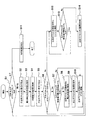
次に、MIP画像作成部12の動作手順について図4を用いて説明する。
Next, the operation procedure of the MIP
まず、MIP画像作成部12は、投影面24上の画素に対して演算を行うか否かを判断する(ステップS1)。MIP画像作成部12は、ステップS1において演算を行うと判定した場合、注目ボクセルを0番目のボクセルに設定する。すなわち、MIP画像作成部12は、視線22上のボリュームデータ23のうち最も視点21に近いボリュームデータ23を注目ボクセルのボクセルデータとして設定する(ステップS2)。MIP画像作成部12は、この注目ボクセルに設定された0番目のボクセルの輝度値を最大輝度値の初期値として格納する(ステップS3)。そして、MIP画像作成部12は、0番目のボクセルのZ座標をZ座標の初期値として例えば0とし、前記最大輝度値の初期値とともに格納する(ステップS4)。
First, the MIP
次に、MIP画像作成部12は、注目ボクセルを0番目に隣接する1番目のボクセルに設定する。すなわち、MIP画像作成部12は、注目ボクセルを0番目から視線方向の奥側へ1ボクセル分移動させる(ステップS5)。そして、MIP画像作成部12は、新たに設定した注目ボクセルがボリュームデータ23の範囲内であるか否かを判定する(ステップS6)。そして、MIP画像作成部12は、新たに設定した注目ボクセルがボリュームデータ23の範囲内であるとステップS6において判定した場合、格納した0番目のボクセルの輝度値と新たに設定した1番目のボクセルの輝度値との比較を行う(ステップS7)。ステップS7において、注目ボクセルである1番目のボクセルの輝度値が0番目のボクセルの輝度値よりも大きい場合、MIP画像作成部12は、注目ボクセルの輝度値を最大輝度値として格納する(ステップS8)。MIP画像作成部12は、この格納した最大輝度値を有する注目ボクセルのZ座標を例えば1とし、新たに求めた最大輝度値とともに格納する(ステップS9)。そして、MIP画像作成部12は、注目ボクセルを1番目のボクセルから視線方向の奥側へ1ボクセル分移動させる(ステップS10)。ステップS7において、注目ボクセルである1番目のボクセルの輝度値が0番目のボクセルの輝度値以下の場合、MIP画像作成部12は、ステップS10に進み、注目ボクセルを1番目のボクセルから視線方向の奥側へ1ボクセル分移動させる。
Next, the MIP
そして、MIP画像作成部12は、ステップS10の後、ステップS6〜ステップS10のステップを繰り返して行う。そして、MIP画像作成部12は、注目ボクセルがボリュームデータ23の範囲から外れたとステップS6において判定した場合、ステップS1に進む。MIP画像作成部12は、投影面の全ピクセルに対してステップS2〜ステップS10の演算を行い、投影面の全ピクセルにおいて演算が完了したら、演算されたMIP画像を投影面上に表示する(ステップS11)。
The MIP
以上のように演算されたMIP画像について、図5A及び5Bを用いて説明する。 The MIP image calculated as described above will be described with reference to FIGS. 5A and 5B.
図5Aに模式的に示す視線方向A、視線方向B及び視線方向Cのそれぞれについて輝度値の変化を表すグラフの例を、図5Bに模式的に示す。図5Bのそれぞれのグラフにおいて、横軸は各視線方向のボクセルのZ座標を表し、縦軸は各Z座標におけるボクセルの輝度値を表す。図4で説明したように各視線方向で最大輝度値を有するボクセルのZ座標を求める場合、各視線方向で最大輝度値を有するボクセルのZ座標を結ぶ線が、図5A及び5Bに示すように小刻みに折れ曲がった線となって認識しにくいことがある。 FIG. 5B schematically shows an example of a graph representing a change in luminance value for each of the viewing direction A, the viewing direction B, and the viewing direction C schematically shown in FIG. 5A. In each graph of FIG. 5B, the horizontal axis represents the Z coordinate of the voxel in each viewing direction, and the vertical axis represents the luminance value of the voxel at each Z coordinate. When obtaining the Z coordinate of the voxel having the maximum luminance value in each line-of-sight direction as described in FIG. 4, the line connecting the Z coordinates of the voxels having the maximum luminance value in each line-of-sight direction is as shown in FIGS. 5A and 5B. It may be difficult to recognize as a broken line.
そこで、図6に示すMIP画像作成部12の動作手順の他の実施形態では、閾値を用いて輝度値を処理する。図6において、図4で説明した部分と同様の部分には同様の参照符号を付して、その説明を省略する。
Therefore, in another embodiment of the operation procedure of the MIP
図6において、MIP画像作成部12は、注目ボクセルがボリュームデータ23の範囲から外れたとステップS6において判定した場合、注目ボクセルを視線方向にマイナス1ボクセル分移動させる(即ち、注目ボクセルを視線方向の手前側へ1ボクセル分戻す)(ステップS12)。そして、MIP画像作成部12は、注目ボクセルの輝度値と予め設定された閾値との比較を行う(ステップ13)。ステップS13において、注目ボクセルの輝度値が予め設定された閾値よりも大きい場合、MIP画像作成部12は、ステップS12に戻り、注目ボクセルを視線方向に更にマイナス1ボクセル分移動させる。ステップS13において、注目ボクセルの輝度値が予め設定された閾値以下の場合、MIP画像作成部12は、この閾値の輝度値を有するボクセルのZ座標を最大輝度値を有するボクセルのZ座標とみなして格納し(ステップS14)、ステップS1へ進む。
In FIG. 6, when it is determined in step S6 that the target voxel is out of the range of the
輝度値の変化が図5A及び5Bと同一の例について、MIP画像作成部12が図6に示す動作を行った場合、図7A及び7Bに示すように、各視線方向で閾値の輝度値を有するボクセルのZ座標を結ぶ線は、図5A及び5Bに示す最大輝度値を有するボクセルのZ座標を結ぶ線に比べて滑らかであるので、MIP画像の表示が認識しやすい。
When the MIP
ここで、輝度値の閾値は、プログラムで自動的に設定してもよいし、検者がマニュアルで入力してもよい。プログラムで設定する場合は、ステップS8で格納された最大輝度値に1未満のある定数を掛け合わせた値を閾値として用いればよい。 Here, the threshold value of the luminance value may be automatically set by a program, or may be manually input by an examiner. When setting by a program, a value obtained by multiplying the maximum luminance value stored in step S8 by a constant less than 1 may be used as the threshold value.
また、ステップS13での判定条件として、「注目ボクセルの輝度値が予め設定された閾値よりも大きい」に代えて、「注目ボクセルにおける輝度値の勾配(即ち、図7Bに示す各グラフの勾配)がある閾値以下である」を用いてもよい。この場合、注目ボクセルの近傍3ボクセル又は近傍9ボクセルを用いて輝度値の勾配を算出する。近傍3ボクセルとは、注目ボクセルから視線方向(Z方向)にマイナス1移動したボクセル、注目ボクセルから視線方向にプラス1移動したボクセル、及び注目ボクセル自身である。近傍9ボクセルとは、注目ボクセルを中心としてX方向、Y方向、Z方向(視線方向)にプラスマイナス1の範囲内にある9つのボクセルである。
Further, instead of “the luminance value of the target voxel is larger than a preset threshold” as the determination condition in step S13, “the gradient of the luminance value in the target voxel (that is, the gradient of each graph shown in FIG. 7B)”. May be used ". In this case, the gradient of the luminance value is calculated using the neighboring 3 voxels or the neighboring 9 voxels of the target voxel. The three neighboring voxels are voxels that have moved minus one from the target voxel in the viewing direction (Z direction), voxels that have moved one plus from the target voxel in the viewing direction, and the target voxel itself. The nine neighboring voxels are nine voxels in the range of plus or
次に、位置関係表示画像作成部14の動作手順について図8を用いて説明する。
Next, the operation procedure of the positional relationship display
まず、位置関係表示画像作成部14は、MIP画像作成部12で作成されたMIP画像を読み込む(ステップS20)。そして、位置関係表示画像作成部14は、MIP画像の三次元空間上に切断面作成部13で作成された切断面を読み込む(ステップS21)。そして、位置関係表示画像作成部14は、位置関係表示画像上のピクセルに対してMIP画像と切断面との相互位置関係に基づく画像作成演算を行うか否かを判断する(ステップS22)。位置関係表示画像作成部14は、MIP画像の視線22上で最大輝度値を有するボクセルのZ座標値と、切断面作成部13で作成された切断面の投影面における切断面のZ座標値とを比較することにより、MIP画像及び切断面のどちらが視点21に近いかを判定する(ステップS23)。そして、位置関係表示画像作成部14は、MIP画像及び切断面のうち視点21により近いと判定された画像から順番に半透明合成する。ここで、MIP画像及び切断面にはそれぞれ不透明度が予め設定されており、それらの不透明度に応じた割合で輝度が加算される(ステップS24)。
First, the positional relationship display
具体的には、MIP画像が切断面よりも視点21に近い場合には、ステップS24において、位置関係表示画像の輝度は次の式(3)により算出される:
Specifically, when the MIP image is closer to the
(数3)
LP=LM×OM+(1−OM)×LS×OS (3)
ここで、LPは位置関係表示画像の輝度であり、LMはMIP画像の輝度であり、LSは切断面の輝度であり、OMはMIP画像の不透明度であり、OSは切断面の不透明度であり、(1−OM)はMIP画像の透明度に相当する。(Equation 3)
L P = L M × O M + (1−O M ) × L S × O S (3)
Here, L P is the intensity of the positional relationship display image, L M is the luminance of the MIP image, L S is the luminance of the cut surface, O M is the opacity of the MIP image, O S is cut a opacity of the surface, (1-O M) corresponds to the transparency of the MIP image.
一方、切断面がMIP画像よりも視点21に近い場合には、ステップS24において、位置関係表示画像の輝度は次の式(4)により算出される:
On the other hand, if the cut surface is closer to the
(数4)
LP=LS×OS+(1−OS)×LM×OM (4)
ここで、(1−OS)は切断面の透明度に相当する。(Equation 4)
L P = L S × O S + (1−O S ) × L M × O M (4)
Here, (1-O S ) corresponds to the transparency of the cut surface.
次に、位置関係表示画像作成部14は、位置関係表示画像上の全ピクセルに対してMIP画像と切断面との相互位置関係に基づく画像作成演算が完了したとステップS22において判断したら、演算した位置関係表示画像を表示部15に表示させる(ステップS25)。
Next, the positional relationship display
以上説明したように、本発明の第1の実施形態によれば、MIP画像と切断面との相互位置関係に基づいて位置関係表示画像を作成して表示することにより、MIP画像と切断面との相互位置関係を検者に明確に把握させることができる。 As described above, according to the first embodiment of the present invention, by creating and displaying the positional relationship display image based on the mutual positional relationship between the MIP image and the cut surface, the MIP image and the cut surface are displayed. It is possible to make the examiner clearly grasp the mutual positional relationship between the two.
次に、本発明の第2の実施形態を、図9及び10を用いて説明する。第2の実施形態が第1の実施形態と異なる点は、表示画像として被検体の体表画像を加えて、MIP画像と切断面と体表画像との相互位置関係を表すように、位置関係表示画像が作成され表示されることである。体表画像が加えられた位置関係表示画像は、リアルタイムバーチャルソノグラフィ(RVS)のガイド画像として用いることができる。RVSとは、超音波診断装置により被検体の超音波画像が撮像される際に、撮像中の超音波画像の表示断面に一致するリファレンス画像(例えばCT断層画像)が、種々の医用画像診断装置(例えばCT画像診断装置)により事前に取得された被検体に関する三次元ボリュームデータから抽出され、抽出されたリファレンス画像が撮像中の超音波画像と並列に表示画面に表示される技術である。これにより、超音波診断装置において、撮像中の超音波画像と同一断面のリファレンス画像をリアルタイムで描画することができる。 Next, a second embodiment of the present invention will be described with reference to FIGS. The second embodiment differs from the first embodiment in that the positional relationship is such that the body surface image of the subject is added as a display image and the mutual positional relationship among the MIP image, the cut surface, and the body surface image is represented. A display image is created and displayed. The positional relationship display image to which the body surface image is added can be used as a guide image for real-time virtual sonography (RVS). RVS refers to a medical image diagnostic apparatus in which reference images (for example, CT tomographic images) that coincide with the display section of an ultrasonic image being imaged are captured when an ultrasonic image of the subject is captured by the ultrasonic diagnostic apparatus. This is a technique in which the extracted reference image is displayed on the display screen in parallel with the ultrasonic image being captured, which is extracted from the three-dimensional volume data regarding the subject acquired in advance by a CT image diagnostic apparatus (for example, a CT image diagnostic apparatus). Thereby, in the ultrasonic diagnostic apparatus, a reference image having the same cross section as the ultrasonic image being imaged can be drawn in real time.
図9は、第2の実施形態の医用画像診断システムのシステム構成図である。超音波診断装置57は、被検体との間で超音波を送受する超音波探触子(以下、探触子という)50と、探触子50に駆動信号を供給する共に探触子50から出力される受信信号を処理して受信データを出力する超音波送受信部51と、超音波送受信部51から出力された受信データに基づいて超音波画像を再構成する超音波画像作成部52と、超音波画像作成部52から出力された超音波画像を表示する表示部56と、を含む。
FIG. 9 is a system configuration diagram of the medical image diagnostic system according to the second embodiment. The ultrasonic
超音波診断装置57は、更に、医用画像診断装置10により取得された被検体に関するボリュームデータを取り込んで記憶するボリュームデータ記憶部11を備えている。
The ultrasonic
探触子50には、駆動信号を超音波に変換して被検体の対象部位に射出すると共に被検体の対象部位から発生した反射エコーを受波して受信信号に変換する、診断用振動子が複数配列されている。診断用振動子に加えて、被検体の対象部位に治療用超音波を射出する治療用振動子が、探触子50に複数配列されていてもよい。
The
超音波診断装置57は、磁気位置センサシステムを備えている。磁気位置センサシステムは、被検体が載置されるベッドなどに取り付けられた磁場発生器(不図示)と、探触子50に取り付けられた磁気信号検出器(磁気センサ)53と、磁気センサ53から出力された検出信号に基づいて探触子50の三次元位置や傾き(ねじれ)等を表すデータ(以下、位置データという)を算出して超音波断層面座標算出部54及び切断面作成部13に出力する位置データ算出部59と、を有する。
The ultrasonic
超音波断層面座標算出部54は、探触子50の位置データを取得してリファレンス画像構成部55に出力する。リアルタイム撮像のときは、リファレンス画像構成部55は、現に撮像されている超音波画像に対応する位置データを超音波断層面座標算出部54からリアルタイムに取得する。
The ultrasonic tomographic plane coordinate
ボリュームデータ記憶部11は、医用画像診断装置10が取得したボリュームデータをその三次元位置座標とともにメモリなどに記憶するものであり、様々な画像診断装置が取得した複数種類のボリュームデータを記憶することもできる。
The volume
リファレンス画像構成部55は、超音波断層面座標算出部54から出力された探触子50の位置データに基づき、ボリュームデータ記憶部11に記憶されたボリュームデータからリファレンス画像用データを抽出してリファレンス画像を再構成する。このリファレンス画像用データは、リアルタイム撮像のときは、現に撮像されている超音波画像のスキャン面に対応する。リファレンス画像は、撮像されている超音波画像と同一断面の断層像として表示部56に表示される。
The reference
超音波診断装置57は、探触子50のガイド情報を作成する手段として、ボリュームデータ記憶部11に記憶されたボリュームデータに基づいてMIP画像及びサーフェイスレンダリング(SR)画像を作成してそれらを合成する三次元画像作成部58と、三次元空間の切断面を作成する切断面作成部13と、MIP画像と切断面との相互位置関係を表す位置関係表示画像を作成する位置関係表示画像作成部14と、を備えている。位置関係表示画像作成部14で作成された位置関係表示画像が探触子50のガイド情報となり、検者はガイド情報に基づいて探触子50を移動させる。なお、超音波診断装置57は、各構成要素を制御する制御部及び操作部(不図示)を備えている。
The ultrasound
ここで、ガイド情報の作成について詳細に説明する。三次元画像作成部58は、ボリュームデータ記憶部11に記憶されたボリュームデータに基づいて第1の実施形態で説明したMIP法を用いてMIP画像を作成すると共に、ボリュームデータ記憶部11に記憶されたボリュームデータに基づいてサーフェイスレンダリング(SR)法やボリュームレンダリング(VR)法を用いて被検体の体表を表す画像(ここでは、SR画像と称することとする)を作成する。
Here, the creation of guide information will be described in detail. The three-dimensional
サーフェイスレンダリング法では、ボリュームデータに対して視点及び投影面が検者により設定され、ボリュームデータから閾値処理などによって被検体の表面境界が抽出され、投影面上の各画素(座標(X,Y))への投影値として、視線ベクトルと境界面の法線ベクトルとのなす角度をもととした陰影処理結果が投影値に反映される。このとき、奥行き情報(Z座標)には表面境界のZ座標が採用される。 In the surface rendering method, the viewpoint and the projection plane are set by the examiner with respect to the volume data, the surface boundary of the subject is extracted from the volume data by threshold processing or the like, and each pixel (coordinate (X, Y)) on the projection plane is extracted. As a projection value to (), the shadow processing result based on the angle formed by the line-of-sight vector and the normal vector of the boundary surface is reflected in the projection value. At this time, the Z coordinate of the surface boundary is adopted as the depth information (Z coordinate).
ボリュームレンダリング法では、ボリュームデータに対して視点及び投影面が検者により設定され、投影面上の各画素(座標(X,Y))への投影値として、視線上にあるボクセルの輝度が各画素の不透明度によって重み付けされながら加算される。このとき、奥行き情報(Z座標)には、輝度値がある閾値より大きくなった個所のZ座標又は輝度勾配がある閾値より大きくなった個所のZ座標が採用される。 In the volume rendering method, the viewpoint and the projection plane are set by the examiner for the volume data, and the brightness of the voxel on the line of sight is set as the projection value to each pixel (coordinate (X, Y)) on the projection plane. It is added while being weighted by the opacity of the pixel. At this time, as the depth information (Z coordinate), the Z coordinate of the location where the luminance value is greater than a certain threshold value or the Z coordinate of the location where the luminance gradient is greater than the certain threshold value is adopted.
三次元画像作成部58は、血管部分の画像をMIP法で作成し被検体の体表の画像をサーフェイスレンダリング法やボリュームレンダリング法で作成して三次元画像を作成する際、三次元空間におけるMIP画像及びSR画像の奥行き情報(Z座標)を併せて算出する。
The three-dimensional
三次元画像作成部58は、上述の通り作成したMIP画像とSR画像とを合成する。三次元画像作成部58は、MIP画像とSR画像とを合成する際、MIP画像のZ座標とSR画像のZ座標とを比較することにより、MIP画像及びSR画像のうち視点21からより遠く他方の陰になって見えない一方に対して陰面処理を施す。通常、血管の画像(MIP画像)が体表の画像(SR画像)より奥側に配置される。このとき、MIP画像及びSR画像に対してそれぞれ不透明度を設定しておき、不透明度に応じた係数及びZ座標値に応じた割合でMIP画像の輝度値とSR画像の輝度値とをブレンドすることで、手前側のSR画像が半透明に表示され、奥側のMIP画像がSR画像を透過して表示されるようにする。この合成された三次元画像は、被検体体表と血管との位置関係を表現しているので、被検体内のどこの血管が表示されているか、また、血管のどの位置からどの方向を観察しているかを、検者に明確に把握させることができる。
The three-dimensional
切断面作成部13は、位置データ算出部59から出力された磁気センサ53の位置データ(探触子50の三次元位置と傾き(ねじれ))に基づいて、三次元空間内における切断面を作成する。具体的には、切断面作成部13は、探触子50の三次元位置に基づいて第1の実施形態で説明した平面式(式(2))において(X0,Y0,Z0)を変化させることにより、切断面の三次元位置を探触子50の三次元位置に応じて移動させる。また、切断面作成部13は、探触子50の傾き(ねじれ)に基づいて第1の実施形態で説明した回転成分R(式(1))を変化させて、切断面を切断面の中心を支点として回転させることにより、切断面を、探触子50の回転に応じて、切断面の中心を通る切断面の法線を軸として回転させる。The cut
位置関係表示画像作成部14は、三次元画像作成部58で作成されたMIP画像とSR画像とが合成された三次元画像と、切断面作成部13で作成された切断面との相互位置関係を表す位置関係表示画像を作成する。
The positional relationship display
MIP画像とSR画像と切断面との関係については、第1の実施形態で説明したのと同様に、MIP画像、SR画像及び切断面について、それぞれのZ座標値が比較され、視点21に近い画像順に並べ替えられ(Z順に並べ替えられ)、陰面処理が施される。そして、視点21に近い方の画像ほど手前側に表示される。
As for the relationship between the MIP image, the SR image, and the cut surface, the Z coordinate values of the MIP image, the SR image, and the cut surface are compared and close to the
ここで、位置関係表示画像の作成方法としては、MIP画像、SR画像及び切断面のそれぞれに不透明度を設定しておき、不透明度が高いほど係数を重くしてZ順に輝度値を重み付け加算する。具体的には、例えば、投影面の或る位置(X,Y)において、視点21から切断面、SR画像、MIP画像という順序で並んでいて、切断面及びSR画像の不透明度を低く、MIP画像の不透明度を高く設定した場合、位置関係表示画像において、視点から手前側の切断面及びSR画像が半透明で表示され、その奥側にあるMIP画像が切断面及びSR画像を透過して表示される。さらに、MIP画像のZ座標値と切断面のZ座標値とが等しい場合は、位置関係表示画像上の位置(X,Y)において輝度値を例えば青色に設定し、SR画像のZ座標値と切断面のZ座標値とが等しい場合は、位置関係表示画像上の位置(X,Y)において輝度値を例えば黄色に設定する。これにより、位置関係表示画像において、切断面とMIP画像との境界線が青色、切断面とSR画像との境界線が黄色で表現され、明瞭になる。
Here, as a method for creating the positional relationship display image, opacity is set for each of the MIP image, the SR image, and the cut surface, and the higher the opacity, the more the coefficient is weighted and the luminance value is weighted and added in the Z order. . Specifically, for example, at a certain position (X, Y) on the projection plane, the cut plane, the SR image, and the MIP image are arranged in this order from the
図10に示すように、表示部56は、位置関係表示画像部14で作成された位置関係表示画像60、超音波画像作成部52で作成された超音波画像63、及びリファレンス画像構成部55で作成されたリファレンス画像64を表示する。
As shown in FIG. 10, the
位置関係表示画像60では、MIP画像として表示された血管31、32、33の画像と共に切断面34が表示されているので、検者は、血管31、32及び33のそれぞれと切断面34との位置関係から、血管32が最も手前側に位置し、血管31が最も奥側に位置し、血管33が血管32と血管31との間に位置することを把握することができ、血管31、32及び33の奥行き関係を把握することができる。更に、合成画像60では、被検体の体表を表すSR画像36が血管31、32、33の画像及び切断面34と共に表示されているので、検者は、被検体の体表と血管31、32及び33との立体的な位置関係を把握することができる。
In the positional
超音波画像63及びリファレンス画像64は、切断面34に対応する被検体の断層像である。超音波画像63及びリファレンス画像64のそれぞれに、切断面34によって切断される血管31、32及び33の断面にそれぞれ対応する断面像65、66及び67が表示される。したがって、検者は、超音波画像63及びリファレンス画像64からも、血管31、32及び33の奥行き関係を把握することができる。
The
表示部56に表示される表示画面は、撮像中の超音波画像63が表示される表示エリア61と、超音波画像63と表示断面が同一のリファレンス画像64が表示される表示エリア62と、合成画像60のガイド情報が表示される表示エリアと、を有している。表示エリア61及び表示エリア62を横並びに配置し、合成画像60のガイド情報が表示される表示エリアを表示エリア61及び表示エリア62の下方に配置してもよい。これらの表示形態に限られず、診断に支障のない範囲内で、合成画像のガイド情報が表示される表示エリアの位置を変更してもよい。また、超音波画像を撮像している探触子50の位置をボディーマークに重ねて表示することが望ましい。更に、検者が操作部を介して各表示エリアの表示画面内での位置を移動できるようにしてもよい。
The display screen displayed on the
図11A、11B及び11Cは、超音波画像63の形状を説明する図である。図10に示す実施形態の超音波画像63は、コンベックス形の超音波探触子50により得られたものであり、図11Aに示すように、探触子50のプローブ半径PR並びに超音波画像63の視野F及び深度Dが超音波画像63の形状によって表されている。図10に示す実施形態では、切断面34及びリファレンス画像64の形状が、コンベックス形とされ、超音波画像63の形状と統一されている。
11A, 11B, and 11C are diagrams illustrating the shape of the
図11Bはリニア形の超音波探触子50により得られた超音波画像63を説明する図であり、図11Cはセクター形の超音波探触子50により得られた超音波画像63を説明する図であり、それぞれにおいて、超音波画像63の視野F及び深度Dが超音波画像63の形状によって表されている。なお、超音波探触子は三次元スキャン形であってもよい。これらの超音波画像63の形状に合わせて、切断面34及びリファレンス画像64の形状が決められることが望ましい。
FIG. 11B is a diagram for explaining an
以上の実施の形態では、三次元画像の例としてMIP画像が説明されているが、MIP画像の他にボリュームレンダリングによる三次元画像やMinIP(Minimum Intensity Projection)画像を適用してもよい。MinIP処理は、視線22上のそれぞれのボクセルについて最小値を取り出して投影画像を得る処理である。
In the above embodiment, an MIP image has been described as an example of a three-dimensional image. However, a three-dimensional image by volume rendering or a MinIP (Minimum Intensity Projection) image may be applied in addition to the MIP image. The MinIP process is a process for obtaining a projection image by extracting a minimum value for each voxel on the line of
以上の実施の形態では、MIP画像やSR画像に切断面を合成する際、それぞれの画素の輝度すなわち画像の不透明度を調整して合成することにより奥行きが表現されているが、画素の色相やその他の画像要素を調整してもよい。 In the above embodiment, when the cut surface is combined with the MIP image or SR image, the depth is expressed by adjusting the luminance of each pixel, that is, the opacity of the image, but the pixel hue or Other image elements may be adjusted.
また、以上の実施の形態では、超音波探触子50の三次元位置情報を得るために磁気センサ53が用いられているが、赤外線や超音波等により三次元位置情報を得るセンサを用いてもよい。
In the above embodiment, the
以上説明した画像表示方法及び医用画像診断システムによれば、奥行き情報を付与した三次元画像を作成して表示することができる。 According to the image display method and the medical image diagnosis system described above, it is possible to create and display a three-dimensional image with depth information.
Claims (21)
ボリュームデータに基づいて、最大輝度投影法によって三次元画像を作成する三次元画像作成ステップと、
前記三次元画像を任意の位置で切断する切断面を設定する切断面設定ステップと、
前記医用画像診断システムの位置関係表示画像作成手段が、前記三次元画像と前記切断面とを合成することにより前記三次元画像と前記切断面との前記最大輝度投影法における投影方向での相互位置関係を表す位置関係表示画像を作成する位置関係表示画像作成ステップであって、前記三次元画像の視線上で最大輝度値を有するボクセルの座標値と前記切断面の投影面における座標値とに基づいて、前記三次元画像と前記切断面のどちらが視点に近いか前記位置関係表示画像作成手段が判定し、前記切断面が前記三次元画像よりも前記視点に近いと前記位置関係表示画像作成手段が判定した場合、前記三次元画像のうち前記切断面によって隠れる部分が前記位置関係表示画像において前記切断面越しに視認可能であるように前記位置関係表示画像の輝度を、前記切断面及び前記三次元画像の不透明度を用いて前記位置関係表示画像作成手段が調整し、前記三次元画像が前記切断面よりも前記視点に近いと前記位置関係表示画像作成手段が判定した場合、前記切断面のうち前記三次元画像によって隠れる部分が前記位置関係表示画像において前記三次元画像越しに視認可能であるように前記位置関係表示画像の輝度を、前記切断面及び前記三次元画像の不透明度を用いて前記位置関係表示画像作成手段が調整する、位置関係表示画像作成ステップと、
を含むことを特徴とする画像表示方法。 A method of displaying an image by a medical diagnostic imaging system,
A three-dimensional image creation step for creating a three-dimensional image by a maximum brightness projection method based on the volume data;
A cutting plane setting step for setting a cutting plane for cutting the three-dimensional image at an arbitrary position;
Positional relationship display image creating device of the medical image diagnostic system, in the projection direction of said maximum intensity projection of the three-dimensional image and the cutting plane and the cutting plane and by Ri before Symbol three-dimensional image to be synthesized A positional relationship display image creating step for creating a positional relationship display image representing a mutual positional relationship between the coordinate values of the voxel having the maximum luminance value on the line of sight of the three-dimensional image and the coordinate values on the projection plane of the cut surface Based on the above, the positional relationship display image creation means determines which of the three-dimensional image and the cut surface is closer to the viewpoint, and when the cut surface is closer to the viewpoint than the three-dimensional image, the positional relationship display image If creating means determines the positional relationship display as part hidden by the cutting plane are visible on the cutting surface over at the positional relationship display image of the three-dimensional image The brightness of an image, the cutting plane and the three-dimensional the positional relationship display image creating device is adjusted using the opacity of the image, and the positional relationship display image closer to the viewpoint than the three-dimensional image the cutting surface If creating means determines the luminance of the positional relationship display image as part hidden by the three-dimensional image is visible in the three-dimensional image over at the positional relationship display image of the cutting plane, said cutting plane and the positional relationship display image creating device is adjusted using the opacity of the three-dimensional image, the positional relationship display image creating step,
An image display method comprising:
前記位置関係表示画像作成ステップにおいて、前記三次元画像と前記切断面と前記体表画像との相互位置関係を表すように前記位置関係表示画像が作成される、ことを特徴とする請求項1記載の画像表示方法。 A body surface image creating step of creating a body surface image of the subject based on the volume data;
2. The positional relationship display image is created in the positional relationship display image creating step so as to represent a mutual positional relationship among the three-dimensional image, the cut surface, and the body surface image. Image display method.
前記ボリュームデータに基づいて、最大輝度投影法によって三次元画像を作成する三次元画像作成手段と、
前記三次元画像と切断面を合成することにより、前記三次元画像と前記切断面との前記最大輝度投影法における投影方向での相互位置関係を表す位置関係表示画像を作成する位置関係表示画像作成手段であって、前記三次元画像の視線上で最大輝度値を有するボクセルの座標値と前記切断面の投影面における座標値とに基づいて、前記三次元画像と前記切断面のどちらが視点に近いか判定し、前記切断面が前記三次元画像よりも前記視点に近いと判定された場合、前記三次元画像のうち前記切断面によって隠れる部分が前記位置関係表示画像において前記切断面越しに視認可能であるように前記位置関係表示画像の輝度を、前記切断面及び三次元画像の不透明度を用いて調整し、前記三次元画像が前記切断面よりも前記視点に近いと判定された場合、前記切断面のうち前記三次元画像によって隠れる部分が前記位置関係表示画像において前記三次元画像越しに視認可能であるように前記位置関係表示画像の輝度を、前記切断面及び三次元画像の不透明度を用いて調整する位置関係表示画像作成手段と、
を備えることを特徴とする医用画像診断システム。 Volume data storage means for storing volume data relating to the subject;
3D image creating means for creating a 3D image by a maximum brightness projection method based on the volume data;
Creating a positional relationship display image that creates a positional relationship display image representing a mutual positional relationship between the three-dimensional image and the cut surface in the projection direction in the maximum luminance projection method by combining the three-dimensional image and the cut surface. The means is based on the coordinate value of the voxel having the maximum luminance value on the line of sight of the three-dimensional image and the coordinate value on the projection surface of the cut surface, which of the three-dimensional image and the cut surface is closer to the viewpoint If it is determined that the cut surface is closer to the viewpoint than the three-dimensional image, a portion of the three-dimensional image that is hidden by the cut surface is visible through the cut surface in the positional relationship display image. The brightness of the positional relationship display image is adjusted using the opacity of the cut surface and the three-dimensional image so that the three-dimensional image is determined to be closer to the viewpoint than the cut surface. In this case, the luminance of the positional relationship display image is set so that a portion hidden by the three-dimensional image of the cut surface is visible through the three-dimensional image in the positional relationship display image. Positional relationship display image creation means for adjusting using opacity;
A medical image diagnostic system comprising:
前記探触子に駆動信号を供給すると共に、前記探触子から出力される受信信号を処理して受信データを出力する超音波送受信手段と、
前記超音波送受信手段から出力された前記受信データに基づいて超音波画像を再構成する超音波画像作成手段と、
前記位置関係表示画像及び前記超音波画像の少なくとも一方を表示する表示手段と、
を更に備えることを特徴とする請求項15記載の医用画像診断システム。 A probe for transmitting and receiving ultrasonic waves to and from the subject;
An ultrasonic transmission / reception means for supplying a drive signal to the probe, processing a reception signal output from the probe, and outputting reception data;
Ultrasound image creating means for reconstructing an ultrasound image based on the received data output from the ultrasound transmitting and receiving means;
Display means for displaying at least one of the positional relationship display image and the ultrasonic image;
The medical image diagnostic system according to claim 15, further comprising:
前記位置情報取得手段により取得された前記探触子の前記位置情報に基づいて、前記切断面に前記三次元画像に対して移動及び回転の少なくとも一方をさせる切断面移動手段と、
を更に備えることを特徴とする請求項16記載の医用画像診断システム。 Position information acquisition means for acquiring position information of the probe;
Based on the position information of the probe acquired by the position information acquisition means, cutting surface moving means for causing the cutting surface to move and / or rotate with respect to the three-dimensional image;
The medical image diagnostic system according to claim 16, further comprising:
前記表示手段は、前記リファレンス画像を表示する、
ことを特徴とする請求項17記載の医用画像診断システム。 Reference image creation means for creating a reference image of the same cross section as the ultrasound image based on the volume data and the position information of the probe,
The display means displays the reference image;
18. The medical image diagnostic system according to claim 17, wherein
Priority Applications (1)
| Application Number | Priority Date | Filing Date | Title |
|---|---|---|---|
| JP2007539851A JP5495357B2 (en) | 2005-10-07 | 2006-09-22 | Image display method and medical image diagnostic system |
Applications Claiming Priority (4)
| Application Number | Priority Date | Filing Date | Title |
|---|---|---|---|
| JP2005295108 | 2005-10-07 | ||
| JP2005295108 | 2005-10-07 | ||
| JP2007539851A JP5495357B2 (en) | 2005-10-07 | 2006-09-22 | Image display method and medical image diagnostic system |
| PCT/JP2006/318841 WO2007043310A1 (en) | 2005-10-07 | 2006-09-22 | Image displaying method and medical image diagnostic system |
Publications (2)
| Publication Number | Publication Date |
|---|---|
| JPWO2007043310A1 JPWO2007043310A1 (en) | 2009-04-16 |
| JP5495357B2 true JP5495357B2 (en) | 2014-05-21 |
Family
ID=37942561
Family Applications (1)
| Application Number | Title | Priority Date | Filing Date |
|---|---|---|---|
| JP2007539851A Active JP5495357B2 (en) | 2005-10-07 | 2006-09-22 | Image display method and medical image diagnostic system |
Country Status (5)
| Country | Link |
|---|---|
| US (1) | US8747319B2 (en) |
| EP (1) | EP1935344B1 (en) |
| JP (1) | JP5495357B2 (en) |
| CN (1) | CN101351156B (en) |
| WO (1) | WO2007043310A1 (en) |
Families Citing this family (29)
| Publication number | Priority date | Publication date | Assignee | Title |
|---|---|---|---|---|
| WO2008091583A2 (en) * | 2007-01-23 | 2008-07-31 | Dtherapeutics, Llc | Image-based extraction for vascular trees |
| JP5226360B2 (en) * | 2008-04-08 | 2013-07-03 | 株式会社東芝 | Ultrasonic diagnostic equipment |
| JP5226370B2 (en) * | 2008-04-18 | 2013-07-03 | 株式会社東芝 | Interpretation report creation support system |
| KR20100008217A (en) * | 2008-07-15 | 2010-01-25 | 주식회사 메디슨 | Ultrasonic system and method for operating ultrasonic system |
| JP4466968B2 (en) * | 2008-11-10 | 2010-05-26 | キヤノン株式会社 | Image processing apparatus, image processing method, program, and program storage medium |
| US8948485B2 (en) * | 2009-06-10 | 2015-02-03 | Hitachi Medical Corporation | Ultrasonic diagnostic apparatus, ultrasonic image processing apparatus, ultrasonic image processing program, and ultrasonic image generation method |
| JP5455512B2 (en) * | 2009-09-08 | 2014-03-26 | 株式会社日立メディコ | Medical image display device, medical image display method, and program for executing the same |
| CN102025814A (en) * | 2009-09-11 | 2011-04-20 | 深圳富泰宏精密工业有限公司 | Portable electronic device |
| KR101182891B1 (en) * | 2009-12-09 | 2012-09-13 | 삼성메디슨 주식회사 | Ultrasound system and method for providing compounding image of two-dimensional ultrasound image and three-dimensional ultrasound image |
| JP5551955B2 (en) * | 2010-03-31 | 2014-07-16 | 富士フイルム株式会社 | Projection image generation apparatus, method, and program |
| JP5848709B2 (en) * | 2010-10-28 | 2016-01-27 | 株式会社日立メディコ | Ultrasonic diagnostic apparatus and ultrasonic image display method |
| JP5717543B2 (en) * | 2011-05-30 | 2015-05-13 | ジーイー・メディカル・システムズ・グローバル・テクノロジー・カンパニー・エルエルシー | Ultrasonic diagnostic apparatus and control program therefor |
| JP6147464B2 (en) | 2011-06-27 | 2017-06-14 | 東芝メディカルシステムズ株式会社 | Image processing system, terminal device and method |
| JP6058290B2 (en) * | 2011-07-19 | 2017-01-11 | 東芝メディカルシステムズ株式会社 | Image processing system, apparatus, method, and medical image diagnostic apparatus |
| JP5414906B2 (en) * | 2011-08-05 | 2014-02-12 | 株式会社東芝 | Image processing apparatus, image display apparatus, image processing method, and program |
| WO2013021711A1 (en) * | 2011-08-11 | 2013-02-14 | 株式会社 日立メディコ | Ultrasound diagnostic device and ultrasound image display method |
| CN103781426B (en) * | 2011-09-08 | 2016-03-30 | 株式会社日立医疗器械 | Diagnostic ultrasound equipment and ultrasonic image display method |
| US20130150718A1 (en) * | 2011-12-07 | 2013-06-13 | General Electric Company | Ultrasound imaging system and method for imaging an endometrium |
| US9798856B2 (en) * | 2012-03-21 | 2017-10-24 | Koninklijke Philips N.V. | Clinical workstation integrating medical imaging and biopsy data and methods using same |
| EP2827774A2 (en) | 2012-03-22 | 2015-01-28 | The Cleveland Clinic Foundation | Augmented reconstruction for computed tomography |
| US9301733B2 (en) | 2012-12-31 | 2016-04-05 | General Electric Company | Systems and methods for ultrasound image rendering |
| WO2015048178A2 (en) * | 2013-09-25 | 2015-04-02 | Heartflow, Inc. | Systems and methods for visualizing elongated structures and detecting branches therein |
| KR20150105149A (en) * | 2014-03-07 | 2015-09-16 | 삼성메디슨 주식회사 | Medical Imaging Apparatus for Providing Guide Information and Guide Information Provision Method Thereof |
| JP6677960B2 (en) * | 2014-06-26 | 2020-04-08 | キヤノンメディカルシステムズ株式会社 | Medical image processing apparatus and medical image processing method |
| JP2017189460A (en) * | 2016-04-14 | 2017-10-19 | ザイオソフト株式会社 | Medical image processor, medical image processing method and medical image processing program |
| CN106108944B (en) * | 2016-06-23 | 2019-07-09 | 飞依诺科技(苏州)有限公司 | A kind of display methods and device of ultrasonic wave 3-D image |
| CN110087547A (en) * | 2016-12-22 | 2019-08-02 | 佳能株式会社 | Display control unit, display control method and program |
| CN112907517B (en) * | 2021-01-28 | 2024-07-19 | 上海商汤善萃医疗科技有限公司 | Image processing method, device, computer equipment and storage medium |
| EP4477152A1 (en) * | 2022-02-10 | 2024-12-18 | IHI Corporation | Ultrasonic diagnostic device |
Citations (4)
| Publication number | Priority date | Publication date | Assignee | Title |
|---|---|---|---|---|
| JP2001084409A (en) * | 1999-09-13 | 2001-03-30 | Toshiba Iyo System Engineering Kk | Three-dimensional image processing method and three-dimensional image processing device |
| JP2001224597A (en) * | 1999-11-25 | 2001-08-21 | Olympus Optical Co Ltd | Ultrasonic image processing apparatus |
| WO2001097174A1 (en) * | 2000-06-16 | 2001-12-20 | Imagnosis Inc. | Point inputting device and method for three-dimensional images |
| FR2863085A1 (en) * | 2003-11-28 | 2005-06-03 | Ge Med Sys Global Tech Co Llc | Three-dimensional radiological image processing method for e.g. vascular imaging, involves finding thrombus sections contours in cutting planes, and displaying cutting plane of interests cross sectional view where contours are highlighted |
Family Cites Families (14)
| Publication number | Priority date | Publication date | Assignee | Title |
|---|---|---|---|---|
| JP3187148B2 (en) * | 1991-08-26 | 2001-07-11 | 株式会社東芝 | Ultrasound diagnostic equipment |
| US5720291A (en) * | 1996-03-22 | 1998-02-24 | Advanced Technology Laboratories, Inc. | Three dimensional medical ultrasonic diagnostic image of tissue texture and vasculature |
| JP3365929B2 (en) * | 1996-10-07 | 2003-01-14 | ジーイー横河メディカルシステム株式会社 | Image processing method and image processing apparatus |
| JPH11164833A (en) * | 1997-09-30 | 1999-06-22 | Toshiba Corp | Medical image diagnostic equipment |
| US6511426B1 (en) * | 1998-06-02 | 2003-01-28 | Acuson Corporation | Medical diagnostic ultrasound system and method for versatile processing |
| JP3905644B2 (en) | 1998-06-15 | 2007-04-18 | 東芝医用システムエンジニアリング株式会社 | 3D ultrasound system |
| CA2294572A1 (en) | 1999-01-27 | 2000-07-27 | Affymetrix, Inc. | Genetic compositions and methods |
| JP4421016B2 (en) * | 1999-07-01 | 2010-02-24 | 東芝医用システムエンジニアリング株式会社 | Medical image processing device |
| US6254540B1 (en) | 1999-11-19 | 2001-07-03 | Olympus Optical Co., Ltd. | Ultrasonic image processing apparatus for constructing three-dimensional image using volume-rendering data and surface-rendering data simultaneously |
| US7044913B2 (en) * | 2001-06-15 | 2006-05-16 | Kabushiki Kaisha Toshiba | Ultrasonic diagnosis apparatus |
| JP2003180697A (en) | 2001-12-18 | 2003-07-02 | Olympus Optical Co Ltd | Ultrasonic diagnostic equipment |
| US8102392B2 (en) * | 2003-06-27 | 2012-01-24 | Kabushiki Kaisha Toshiba | Image processing/displaying apparatus having free moving control unit and limited moving control unit and method of controlling the same |
| JP4049323B2 (en) | 2004-03-31 | 2008-02-20 | ソフトバンクテレコム株式会社 | Mobility control apparatus, replica transfer apparatus, mobility control system using these, and mobility control method |
| US7604595B2 (en) * | 2004-06-22 | 2009-10-20 | General Electric Company | Method and system for performing real time navigation of ultrasound volumetric data |
-
2006
- 2006-09-22 EP EP06810454A patent/EP1935344B1/en active Active
- 2006-09-22 JP JP2007539851A patent/JP5495357B2/en active Active
- 2006-09-22 WO PCT/JP2006/318841 patent/WO2007043310A1/en not_active Ceased
- 2006-09-22 US US12/089,425 patent/US8747319B2/en not_active Expired - Fee Related
- 2006-09-22 CN CN2006800372347A patent/CN101351156B/en active Active
Patent Citations (4)
| Publication number | Priority date | Publication date | Assignee | Title |
|---|---|---|---|---|
| JP2001084409A (en) * | 1999-09-13 | 2001-03-30 | Toshiba Iyo System Engineering Kk | Three-dimensional image processing method and three-dimensional image processing device |
| JP2001224597A (en) * | 1999-11-25 | 2001-08-21 | Olympus Optical Co Ltd | Ultrasonic image processing apparatus |
| WO2001097174A1 (en) * | 2000-06-16 | 2001-12-20 | Imagnosis Inc. | Point inputting device and method for three-dimensional images |
| FR2863085A1 (en) * | 2003-11-28 | 2005-06-03 | Ge Med Sys Global Tech Co Llc | Three-dimensional radiological image processing method for e.g. vascular imaging, involves finding thrombus sections contours in cutting planes, and displaying cutting plane of interests cross sectional view where contours are highlighted |
Also Published As
| Publication number | Publication date |
|---|---|
| US8747319B2 (en) | 2014-06-10 |
| EP1935344A1 (en) | 2008-06-25 |
| US20090306504A1 (en) | 2009-12-10 |
| JPWO2007043310A1 (en) | 2009-04-16 |
| CN101351156A (en) | 2009-01-21 |
| EP1935344B1 (en) | 2013-03-13 |
| CN101351156B (en) | 2010-12-01 |
| WO2007043310A1 (en) | 2007-04-19 |
| EP1935344A4 (en) | 2011-05-11 |
Similar Documents
| Publication | Publication Date | Title |
|---|---|---|
| JP5495357B2 (en) | Image display method and medical image diagnostic system | |
| JP5637653B2 (en) | Medical image processing apparatus, ultrasonic diagnostic apparatus, and medical image processing program | |
| JP4470187B2 (en) | Ultrasonic device, ultrasonic imaging program, and ultrasonic imaging method | |
| KR101466153B1 (en) | Medicalimaging apparatus and control method for the same | |
| CN103220980B (en) | Ultrasound diagnostic apparatus and ultrasound image display method | |
| JP4847334B2 (en) | Ultrasonic imaging apparatus and projection image generation method | |
| JP2013536720A (en) | 3D display of 2D ultrasound images | |
| JP5814370B2 (en) | Ultrasonic diagnostic apparatus and ultrasonic image display method | |
| KR20000069171A (en) | Enhanced image processing for a three-dimensional imaging system | |
| JP2009018115A (en) | 3D ultrasonic diagnostic equipment | |
| EP2333577B1 (en) | Methods and systems for defining a VOI in an ultrasound imaging space | |
| JP4282939B2 (en) | Ultrasonic diagnostic apparatus, image processing apparatus, and image processing program | |
| JP4652780B2 (en) | Ultrasonic diagnostic equipment | |
| JP4653324B2 (en) | Image display apparatus, image display program, image processing apparatus, and medical image diagnostic apparatus | |
| CN116263948A (en) | Systems and methods for image fusion | |
| JP2001276066A (en) | Three-dimensional image processor | |
| JP5454841B2 (en) | Medical image processing device | |
| JP5942217B2 (en) | Ultrasonic diagnostic apparatus, ultrasonic image processing apparatus, and ultrasonic image processing program | |
| JP4936281B2 (en) | Ultrasonic diagnostic equipment | |
| JP2021102086A (en) | Optimal ultrasound-based organ segmentation | |
| JP2001128982A (en) | Ultrasound image diagnostic apparatus and image processing apparatus | |
| JP5305635B2 (en) | Medical image display device | |
| JP5487339B2 (en) | Medical image processing device |
Legal Events
| Date | Code | Title | Description |
|---|---|---|---|
| A521 | Request for written amendment filed |
Free format text: JAPANESE INTERMEDIATE CODE: A523 Effective date: 20090914 |
|
| A621 | Written request for application examination |
Free format text: JAPANESE INTERMEDIATE CODE: A621 Effective date: 20090914 |
|
| A131 | Notification of reasons for refusal |
Free format text: JAPANESE INTERMEDIATE CODE: A131 Effective date: 20111028 |
|
| A521 | Request for written amendment filed |
Free format text: JAPANESE INTERMEDIATE CODE: A523 Effective date: 20111227 |
|
| A131 | Notification of reasons for refusal |
Free format text: JAPANESE INTERMEDIATE CODE: A131 Effective date: 20121002 |
|
| A521 | Request for written amendment filed |
Free format text: JAPANESE INTERMEDIATE CODE: A523 Effective date: 20121203 |
|
| A131 | Notification of reasons for refusal |
Free format text: JAPANESE INTERMEDIATE CODE: A131 Effective date: 20130111 |
|
| A521 | Request for written amendment filed |
Free format text: JAPANESE INTERMEDIATE CODE: A523 Effective date: 20130312 |
|
| A131 | Notification of reasons for refusal |
Free format text: JAPANESE INTERMEDIATE CODE: A131 Effective date: 20130918 |
|
| A521 | Request for written amendment filed |
Free format text: JAPANESE INTERMEDIATE CODE: A523 Effective date: 20131029 |
|
| A711 | Notification of change in applicant |
Free format text: JAPANESE INTERMEDIATE CODE: A711 Effective date: 20131114 |
|
| A521 | Request for written amendment filed |
Free format text: JAPANESE INTERMEDIATE CODE: A821 Effective date: 20131114 |
|
| TRDD | Decision of grant or rejection written | ||
| A01 | Written decision to grant a patent or to grant a registration (utility model) |
Free format text: JAPANESE INTERMEDIATE CODE: A01 Effective date: 20140226 |
|
| A61 | First payment of annual fees (during grant procedure) |
Free format text: JAPANESE INTERMEDIATE CODE: A61 Effective date: 20140228 |
|
| R150 | Certificate of patent or registration of utility model |
Ref document number: 5495357 Country of ref document: JP Free format text: JAPANESE INTERMEDIATE CODE: R150 |
|
| S111 | Request for change of ownership or part of ownership |
Free format text: JAPANESE INTERMEDIATE CODE: R313111 |
|
| S533 | Written request for registration of change of name |
Free format text: JAPANESE INTERMEDIATE CODE: R313533 |
|
| R350 | Written notification of registration of transfer |
Free format text: JAPANESE INTERMEDIATE CODE: R350 |
|
| S111 | Request for change of ownership or part of ownership |
Free format text: JAPANESE INTERMEDIATE CODE: R313111 |
|
| R350 | Written notification of registration of transfer |
Free format text: JAPANESE INTERMEDIATE CODE: R350 |
|
| R250 | Receipt of annual fees |
Free format text: JAPANESE INTERMEDIATE CODE: R250 |
|
| R250 | Receipt of annual fees |
Free format text: JAPANESE INTERMEDIATE CODE: R250 |
|
| R250 | Receipt of annual fees |
Free format text: JAPANESE INTERMEDIATE CODE: R250 |
|
| S111 | Request for change of ownership or part of ownership |
Free format text: JAPANESE INTERMEDIATE CODE: R313111 |
|
| R350 | Written notification of registration of transfer |
Free format text: JAPANESE INTERMEDIATE CODE: R350 |
|
| R250 | Receipt of annual fees |
Free format text: JAPANESE INTERMEDIATE CODE: R250 |