JP5472321B2 - Exhaust device for internal combustion engine - Google Patents
Exhaust device for internal combustion engine Download PDFInfo
- Publication number
- JP5472321B2 JP5472321B2 JP2011547089A JP2011547089A JP5472321B2 JP 5472321 B2 JP5472321 B2 JP 5472321B2 JP 2011547089 A JP2011547089 A JP 2011547089A JP 2011547089 A JP2011547089 A JP 2011547089A JP 5472321 B2 JP5472321 B2 JP 5472321B2
- Authority
- JP
- Japan
- Prior art keywords
- pipe
- exhaust
- resonance
- downstream
- upstream
- Prior art date
- Legal status (The legal status is an assumption and is not a legal conclusion. Google has not performed a legal analysis and makes no representation as to the accuracy of the status listed.)
- Expired - Fee Related
Links
Images


Classifications
-
- F—MECHANICAL ENGINEERING; LIGHTING; HEATING; WEAPONS; BLASTING
- F01—MACHINES OR ENGINES IN GENERAL; ENGINE PLANTS IN GENERAL; STEAM ENGINES
- F01N—GAS-FLOW SILENCERS OR EXHAUST APPARATUS FOR MACHINES OR ENGINES IN GENERAL; GAS-FLOW SILENCERS OR EXHAUST APPARATUS FOR INTERNAL-COMBUSTION ENGINES
- F01N1/00—Silencing apparatus characterised by method of silencing
- F01N1/08—Silencing apparatus characterised by method of silencing by reducing exhaust energy by throttling or whirling
- F01N1/084—Silencing apparatus characterised by method of silencing by reducing exhaust energy by throttling or whirling the exhaust gases flowing through the silencer two or more times longitudinally in opposite directions, e.g. using parallel or concentric tubes
-
- F—MECHANICAL ENGINEERING; LIGHTING; HEATING; WEAPONS; BLASTING
- F01—MACHINES OR ENGINES IN GENERAL; ENGINE PLANTS IN GENERAL; STEAM ENGINES
- F01N—GAS-FLOW SILENCERS OR EXHAUST APPARATUS FOR MACHINES OR ENGINES IN GENERAL; GAS-FLOW SILENCERS OR EXHAUST APPARATUS FOR INTERNAL-COMBUSTION ENGINES
- F01N1/00—Silencing apparatus characterised by method of silencing
- F01N1/02—Silencing apparatus characterised by method of silencing by using resonance
- F01N1/023—Helmholtz resonators
-
- F—MECHANICAL ENGINEERING; LIGHTING; HEATING; WEAPONS; BLASTING
- F01—MACHINES OR ENGINES IN GENERAL; ENGINE PLANTS IN GENERAL; STEAM ENGINES
- F01N—GAS-FLOW SILENCERS OR EXHAUST APPARATUS FOR MACHINES OR ENGINES IN GENERAL; GAS-FLOW SILENCERS OR EXHAUST APPARATUS FOR INTERNAL-COMBUSTION ENGINES
- F01N1/00—Silencing apparatus characterised by method of silencing
- F01N1/06—Silencing apparatus characterised by method of silencing by using interference effect
-
- F—MECHANICAL ENGINEERING; LIGHTING; HEATING; WEAPONS; BLASTING
- F01—MACHINES OR ENGINES IN GENERAL; ENGINE PLANTS IN GENERAL; STEAM ENGINES
- F01N—GAS-FLOW SILENCERS OR EXHAUST APPARATUS FOR MACHINES OR ENGINES IN GENERAL; GAS-FLOW SILENCERS OR EXHAUST APPARATUS FOR INTERNAL-COMBUSTION ENGINES
- F01N1/00—Silencing apparatus characterised by method of silencing
- F01N1/08—Silencing apparatus characterised by method of silencing by reducing exhaust energy by throttling or whirling
- F01N1/089—Silencing apparatus characterised by method of silencing by reducing exhaust energy by throttling or whirling using two or more expansion chambers in series
-
- F—MECHANICAL ENGINEERING; LIGHTING; HEATING; WEAPONS; BLASTING
- F01—MACHINES OR ENGINES IN GENERAL; ENGINE PLANTS IN GENERAL; STEAM ENGINES
- F01N—GAS-FLOW SILENCERS OR EXHAUST APPARATUS FOR MACHINES OR ENGINES IN GENERAL; GAS-FLOW SILENCERS OR EXHAUST APPARATUS FOR INTERNAL-COMBUSTION ENGINES
- F01N2210/00—Combination of methods of silencing
- F01N2210/04—Throttling-expansion and resonance
-
- F—MECHANICAL ENGINEERING; LIGHTING; HEATING; WEAPONS; BLASTING
- F01—MACHINES OR ENGINES IN GENERAL; ENGINE PLANTS IN GENERAL; STEAM ENGINES
- F01N—GAS-FLOW SILENCERS OR EXHAUST APPARATUS FOR MACHINES OR ENGINES IN GENERAL; GAS-FLOW SILENCERS OR EXHAUST APPARATUS FOR INTERNAL-COMBUSTION ENGINES
- F01N2470/00—Structure or shape of exhaust gas passages, pipes or tubes
- F01N2470/02—Tubes being perforated
-
- F—MECHANICAL ENGINEERING; LIGHTING; HEATING; WEAPONS; BLASTING
- F01—MACHINES OR ENGINES IN GENERAL; ENGINE PLANTS IN GENERAL; STEAM ENGINES
- F01N—GAS-FLOW SILENCERS OR EXHAUST APPARATUS FOR MACHINES OR ENGINES IN GENERAL; GAS-FLOW SILENCERS OR EXHAUST APPARATUS FOR INTERNAL-COMBUSTION ENGINES
- F01N2470/00—Structure or shape of exhaust gas passages, pipes or tubes
- F01N2470/24—Concentric tubes or tubes being concentric to housing, e.g. telescopically assembled
-
- F—MECHANICAL ENGINEERING; LIGHTING; HEATING; WEAPONS; BLASTING
- F01—MACHINES OR ENGINES IN GENERAL; ENGINE PLANTS IN GENERAL; STEAM ENGINES
- F01N—GAS-FLOW SILENCERS OR EXHAUST APPARATUS FOR MACHINES OR ENGINES IN GENERAL; GAS-FLOW SILENCERS OR EXHAUST APPARATUS FOR INTERNAL-COMBUSTION ENGINES
- F01N2490/00—Structure, disposition or shape of gas-chambers
- F01N2490/02—Two or more expansion chambers in series connected by means of tubes
Landscapes
- Engineering & Computer Science (AREA)
- Chemical & Material Sciences (AREA)
- Combustion & Propulsion (AREA)
- Mechanical Engineering (AREA)
- General Engineering & Computer Science (AREA)
- Exhaust Silencers (AREA)
Description
本発明は、内燃機関の排気装置に関し、特に、排気流の排気方向の最下流に設けられた排気管の気柱共鳴による排気騒音を低減するようにした内燃機関の排気装置に関する。 The present invention relates to an exhaust device for an internal combustion engine, and more particularly, to an exhaust device for an internal combustion engine that reduces exhaust noise due to air column resonance in an exhaust pipe provided at the most downstream in the exhaust direction of the exhaust flow.
自動車等の車両に用いられる内燃機関の排気装置としては、図18に示すようなものが知られている(例えば、特許文献1参照)。図18において、内燃機関としてのエンジン1から排気マニホールド2に排気される排気ガスは、触媒コンバータ3によって浄化された後に、排気装置4に導入される。
As an exhaust device for an internal combustion engine used in a vehicle such as an automobile, one as shown in FIG. 18 is known (for example, see Patent Document 1). In FIG. 18, exhaust gas exhausted from the engine 1 as an internal combustion engine to the
排気装置4は、触媒コンバータ3に連結されたフロントパイプ5、フロントパイプ5に連結されたセンターパイプ6、センターパイプ6に連結された消音器としてのメインマフラ7、メインマフラ7に連結されたテールパイプ8およびテールパイプ8に介装されたサブマフラ9から構成されている。
The exhaust device 4 includes a
図19に示すように、メインマフラ7は、センターパイプ6の小孔6aから排気ガスが拡張されて導入される拡張室7aと、センターパイプ6の下流開口端6bが挿通される共鳴室7bとを備えており、センターパイプ6の下流開口端6bから共鳴室7bに導入される排気ガスは、ヘルムホルツ共鳴によって特定の周波数の排気音が消音される。
As shown in FIG. 19, the main muffler 7 includes an
ここで、小孔6aから共鳴室7bに突出するセンターパイプ6の長さをL1、センターパイプ6の断面積をS、共鳴室7bの容積をV、空気中の音速をCとするとき、空気中の共鳴周波数fnはヘルムホルツ共鳴に基づいて下記の式(1)により求められる。

上記の式(1)から明らかなように、共鳴室7bの容積Vを大きくしたり、センターパイプ6の突出部分の長さL1を長くすることにより、共鳴周波数を低周波数側にチューニングすることができ、共鳴室7bの容積Vを小さくしたり、センターパイプ6の突出部分の長さL1を短くすることにより、共鳴周波数を高周波数側にチューニングすることができる。Here, when a length of the
As apparent from the above equation (1), or by increasing the volume V of the
サブマフラ9は、エンジン1の運転時の排気脈動によってテールパイプ8内でテールパイプ8の管長に対応した気柱共鳴が発生することによって音圧が増大するのを抑制するようになっている。
The sub muffler 9 is configured to suppress an increase in sound pressure due to the occurrence of air column resonance corresponding to the length of the
一般に、排気ガスの排気方向上流側および下流側にそれぞれ上流開口端および下流開口端を有するパイプは、エンジンの運転時の排気脈動による入射波がパイプの上流開口端および下流開口端で反射することにより、パイプの管長を半波長とした周波数の気柱共鳴を基本成分として、その半波長の自然数倍の波長の気柱共鳴が発生する。 In general, in a pipe having an upstream opening end and a downstream opening end on the upstream side and downstream side of the exhaust gas in the exhaust direction, incident waves due to exhaust pulsation during engine operation are reflected at the upstream opening end and the downstream opening end of the pipe. Thus, air column resonance having a wavelength that is a natural number multiple of the half wavelength is generated with air column resonance having a frequency with the pipe length of the half wavelength as a basic component.
例えば、図18において、サブマフラ9が設けられていないテールパイプ8がメインマフラ7から後方に延在している場合を例にすると、図20に示すように、基本振動(一次成分)の気柱共鳴の波長λ1は、テールパイプ8の管長Lの略2倍となり、二次成分の気柱共鳴の波長λ2は、管長Lの略1倍となる。また、三次成分の気柱共鳴の波長λ3は、管長Lの2/3倍となる。このように、テールパイプ8内には上流開口端8aおよび下流開口端8bが音圧の節となるような定在波ができる。
For example, in FIG. 18, taking as an example the case where the
また、テールパイプ8の気柱共鳴周波数fcは、下記の式(2)で表される。
fc=(c/2L)・n......(2)
但し、c:音速、L:テールパイプの管長 n:次数
上記の式(2)から明らかなように、テールパイプ8の管長Lが長い程、気柱共鳴周波数fcが低周波数側に移行して、エンジン1の低回転時に排気音が増大して騒音が悪化してしまい、運転者に不快感を与えてしまうことになる。Further, the air column resonance frequency fc of the
fc = (c / 2L) · n (2)
However, c: sound velocity, L: length of tail pipe n: order As apparent from the above equation (2), the longer the length L of the
特に、図21に示すように、気柱共鳴の一次成分f1および二次成分f2が常用回転域で発生すると、こもり音と呼ばれる不快な騒音が発生してしまい、排気騒音の悪化の原因となる。 In particular, as shown in FIG. 21, when the primary component f1 and the secondary component f2 of the air column resonance are generated in the normal rotation range, an unpleasant noise called a booming noise is generated, which causes deterioration of exhaust noise. .
このため、テールパイプ8の管長が長い場合には、音圧レベルが高い定在波の腹の部分で、かつ、気柱共鳴による排気音の一次成分f1、二次成分f2のそれぞれの腹に対して最適な位置に、メインマフラ7より容量の小さなサブマフラ9を設けることにより、エンジン1の常用回転域において排気騒音を低減して、運転者に不快感を与えてしまうのを防止するようにしている。
For this reason, when the pipe length of the
一方、排気装置4の製造コストや重量を低減するために、サブマフラ9を廃止することが考えられるが、サブマフラ9を廃止すると、テールパイプ8の管長が長くなって、テールパイプ8の気柱共鳴周波数が低周波側に移行してしまう。 On the other hand, in order to reduce the manufacturing cost and weight of the exhaust device 4, it is conceivable to abolish the sub muffler 9. The frequency shifts to the low frequency side.
この場合には、テールパイプ8の上流開口端8aに接続されるメインマフラ7の共鳴室7bの共鳴周波数をテールパイプ8の気柱共鳴周波数に合わせることによって、メインマフラ7の共鳴室7b内においてテールパイプ8の気柱共鳴を消音することが考えられる。
In this case, by adjusting the resonance frequency of the
すなわち、式(1)に基づいて、共鳴室7bの容積Vを大きくしたり、センターパイプ6の突出部分の長さL1を長くして共鳴室7bの共鳴周波数を低周波数側にチューニングすることで、テールパイプ8内で発生する気柱共鳴を共鳴室7bで予め消音することが考えられる。That is, based on equation (1), or by increasing the volume V of the
しかしながら、共鳴室7bのヘルムホルツ共鳴を利用して排気音を消音するようにした場合には、共鳴室7bとテールパイプ8の上流開口端8aとが離隔しているため、共鳴室7bによって気柱共鳴を予め消音するようにしても、テールパイプ8内に発生する定在波の反射の繰り返しによって発生する音がテールパイプ8の下流開口端8bから吐出してしまう。したがって、共鳴室7bのヘルムホルツ共鳴が実際にテールパイプ8内で発生する気柱共鳴に効果的に作用し難く、気柱共鳴を充分に抑制することができない。
However, when the exhaust sound is silenced using the Helmholtz resonance of the
また、車両の減速時にはアクセルペダルが解放されてスロットルバルブが閉じるため、エンジン1から排気装置4に排気される流量が急激に低減された排気流のみとなり、共鳴室7bに導入される空気圧が小さくなる。
Further, when the vehicle is decelerated, the accelerator pedal is released and the throttle valve is closed, so that only the exhaust flow in which the flow rate exhausted from the engine 1 to the exhaust device 4 is drastically reduced is obtained, and the air pressure introduced into the
このため、共鳴室7bにおいてヘルムホルツ共鳴を行うのに充分な空気量を得ることができず、テールパイプ8の気柱共鳴を抑制することが困難となってしまう。車両の減速時にはエンジン1の回転数が急激に低下するため、例えば、2000rpm程度(気柱共鳴による排気音の一次成分f1)の低回転数で車室内にこもり音を生じさせてしまい、運転者に不快感を与えてしまうことになる。
For this reason, it is difficult to obtain an air amount sufficient to perform Helmholtz resonance in the
したがって、気柱共鳴を効果的に抑制するためには、テールパイプ8にサブマフラ9を設ける必要があり、結果的に、サブマフラ9を設ける分だけ排気装置4の重量が増大してしまうとともに、排気装置4の製造コストが増大してしまう。
Therefore, in order to effectively suppress the air column resonance, it is necessary to provide the sub-muffler 9 in the
本発明は、上述のような従来の問題を解決するためになされたもので、従来用いられていたサブマフラを廃止して排気騒音を低減することができ、排気装置の重量を低減することができるとともに、排気装置の製造コストを低減することができる内燃機関の排気装置を提供することを目的とする。 The present invention has been made in order to solve the above-described conventional problems, and can eliminate the conventionally used sub-muffler to reduce exhaust noise and reduce the weight of the exhaust device. Another object of the present invention is to provide an exhaust device for an internal combustion engine that can reduce the manufacturing cost of the exhaust device.
本発明に係る内燃機関の排気装置は、上記目的を達成するため、(1)内燃機関から排出された排気流が導入され、前記排気流を拡張して消音する拡張室および前記拡張室に隣接し、特定の周波数の排気音を消音する共鳴室を有する消音器と、前記排気流の排気方向の上流部に前記消音器の前記拡張室に接続される上流開口端を有するとともに、下流部に前記消音器から排出される排気流を大気に排出するための下流開口端を有する排気管とを備えた内燃機関の排気装置であって、前記排気管の内部に中空部材を設け、前記中空部材は、下流端が開口端を構成し、開口端を構成する上流端が前記排気管の内部から前記排気管の前記上流開口端を通して外方に突出して前記共鳴室に連通することにより、前記共鳴室を画成する前記消音器の壁部によって囲まれる閉空間内に位置し、前記排気管は、前記消音器の内部に設けられたアウターパイプと、前記アウターパイプに接続され、前記アウターパイプから前記消音器の下流側に延在するテールパイプとから構成され、前記中空部材は、前記アウターパイプの内部に設けられたアウトレットパイプから構成され、前記アウトレットパイプの下流部は、前記テールパイプの上流部に接続されるとともに、前記アウトレットパイプの下流部に前記アウトレットパイプの内部と前記アウターパイプの内部とを連通する孔が形成されるものから構成されている。 An exhaust system of an internal combustion engine according to the present invention, in order to achieve the above object, (1) an exhaust stream discharged from the internal combustion engine is introduced, adjacent to the expansion chamber and the expansion chamber for muffling extend the exhaust stream and a muffler having a resonance chamber for muffling the exhaust sound of a specific frequency, which has an upstream open end connected to the muffler of the expansion chamber on the upstream portion of the exhaust direction of the exhaust stream, downstream portion An exhaust system for an internal combustion engine comprising an exhaust pipe having a downstream opening end for discharging an exhaust flow discharged from the silencer to the atmosphere, wherein a hollow member is provided inside the exhaust pipe, and the hollow member The downstream end constitutes an open end, and the upstream end constituting the open end protrudes outward from the inside of the exhaust pipe through the upstream open end of the exhaust pipe and communicates with the resonance chamber. The wall of the silencer that defines the room Therefore positioned in the closed space surrounded, the exhaust pipe, an outer pipe provided inside the silencer is connected to the outer pipe, it extends downstream of the muffler from the outer pipe tail The hollow member is an outlet pipe provided inside the outer pipe, and a downstream portion of the outlet pipe is connected to an upstream portion of the tail pipe, and the outlet pipe It is comprised from the thing in which the hole which connects the inside of the said outlet pipe and the inside of the said outer pipe is formed in a downstream part .
この排気管は、排気管の内部に中空部材が設けられ、中空部材の下流端が開口端を構成するとともに、中空部材の上流端が排気管の内部から外方に突出して共鳴室に連通することにより、共鳴室を画成する消音器の壁部によって囲まれる閉空間内に位置するので、排気管内の排気流の圧力エネルギー、すなわち、空気の圧力エネルギーの圧力分布を中空部材および共鳴室内に発生させて、圧力エネルギーを中空部材および共鳴室に蓄積することができ、気柱共鳴時にこの圧力エネルギーを中空部材および共鳴室内に保持して外部に放出させないようにすることができる。 In this exhaust pipe, a hollow member is provided inside the exhaust pipe, the downstream end of the hollow member forms an open end, and the upstream end of the hollow member projects outward from the interior of the exhaust pipe and communicates with the resonance chamber. Therefore, the pressure energy of the exhaust flow in the exhaust pipe, that is, the pressure distribution of the pressure energy of the air is transferred to the hollow member and the resonance chamber. The pressure energy can be accumulated in the hollow member and the resonance chamber, and the pressure energy can be held in the hollow member and the resonance chamber during the air column resonance so as not to be released to the outside.
この中空部材および共鳴室に空気の圧力エネルギーを蓄積することは、排気管内の空気が持つ圧力エネルギーによって行われ、排気管全体の圧力エネルギーに変化が生じない。したがって、排気管内の圧力エネルギーは、中空部材および共鳴室内の圧力エネルギーと、中空部材と共鳴室とを除いた排気管の圧力エネルギーとに分散することができ、中空部材と共鳴室とを除いた排気管内の圧力エネルギーのみを外部に放出することができる。 Accumulation of the pressure energy of air in the hollow member and the resonance chamber is performed by the pressure energy of the air in the exhaust pipe, and the pressure energy of the entire exhaust pipe does not change. Therefore, the pressure energy in the exhaust pipe can be dispersed into the pressure energy in the hollow member and the resonance chamber, and the pressure energy in the exhaust pipe excluding the hollow member and the resonance chamber, and the hollow member and the resonance chamber are excluded. Only the pressure energy in the exhaust pipe can be released to the outside.
また、中空部材および共鳴室は、圧力エネルギーを蓄積する容量が大きいため、排気管から放出される圧力エネルギーを大幅に低減することができる。
したがって、気柱共鳴時の音圧のピークを下げて音圧レベルを低減することができ、排気騒音を低減することができる。Further, since the hollow member and the resonance chamber have a large capacity for storing pressure energy, the pressure energy released from the exhaust pipe can be greatly reduced.
Therefore, the sound pressure level at the time of air column resonance can be lowered to reduce the sound pressure level, and the exhaust noise can be reduced.
また、気柱共鳴時には排気管内において排気脈動による音波が開口端反射を繰り返すことにより定在波が発生し、排気管の管長と定在波の波長とが特定の関係にあるとき、振幅が著しく大きくなり、気柱共鳴が生じる。 Also, at the time of air column resonance, a standing wave is generated by repeated reflection of the opening end of the sound wave due to the exhaust pulsation in the exhaust pipe. When the length of the exhaust pipe has a specific relationship with the wavelength of the standing wave, the amplitude is remarkably large. It becomes larger and air column resonance occurs.
本発明では、排気管の内部に、排気管の下流側に下流開口端が開口し、共鳴室に連通することにより、共鳴室を画成する消音器の壁部によって囲まれる閉空間内に位置する上流端を有する中空部材を設けたので、音波の伝搬方向に中空部材および共鳴室を対向させることができるとともに、気柱共鳴の発生部位に中空部材の下流開口端を位置させることができる。 In the present invention, a downstream opening end is opened on the downstream side of the exhaust pipe inside the exhaust pipe, and communicates with the resonance chamber so that the exhaust pipe is positioned in a closed space surrounded by the wall of the silencer that defines the resonance chamber. Since the hollow member having the upstream end is provided, the hollow member and the resonance chamber can be opposed to each other in the sound wave propagation direction, and the downstream open end of the hollow member can be positioned at the site where the air column resonance occurs.
このため、中空部材および共鳴室を、気柱共鳴を音源とするヘルムホルツ共鳴室にすることができ、共鳴室の共鳴周波数を排気管の気柱共鳴周波数と一致させるようにすれば、気柱共鳴を抑制することができる。 For this reason, the hollow member and the resonance chamber can be a Helmholtz resonance chamber using air column resonance as a sound source, and if the resonance frequency of the resonance chamber matches the air column resonance frequency of the exhaust pipe, Can be suppressed.
また、気柱共鳴の発生領域に中空部材の下流部を位置させることができるため、減速時に消音器に導入される排気流量が急減した場合であっても、気柱共鳴を充分に抑制することができる。 In addition, since the downstream portion of the hollow member can be positioned in the region where the air column resonance occurs, the air column resonance can be sufficiently suppressed even when the exhaust flow rate introduced into the silencer during deceleration is rapidly reduced. Can do.
このように音圧そのものを低減することができるため、気柱共鳴時および気柱共鳴時以外の運転領域に亘って音圧を低減することができるとともに、気柱共鳴時には音圧の低減に加えてヘルムホルツ共鳴を利用して気柱共鳴をより一層抑制することができる。このため、排気騒音を大幅に低減することができる。 Since the sound pressure itself can be reduced in this way, the sound pressure can be reduced over the operating region other than during the air column resonance and during the air column resonance, and in addition to the reduction of the sound pressure during the air column resonance. Thus, air column resonance can be further suppressed using Helmholtz resonance. For this reason, exhaust noise can be greatly reduced.
この結果、従来用いられていたサブマフラを廃止することができるとともに排気管の上流部に設けられた消音器を小型化することができるため、排気装置の重量を低減することができるとともに、排気装置の製造コストを低減することができる。 As a result, the conventionally used sub-muffler can be abolished, and the silencer provided in the upstream portion of the exhaust pipe can be reduced in size, so that the weight of the exhaust device can be reduced and the exhaust device can be reduced. The manufacturing cost can be reduced.
また、この排気装置は、中空部材を、消音器に既存のアウトレットパイプから構成し、このアウトレットパイプの外周部にアウターパイプを取付け、アウトレットパイプの下流部にアウトレットパイプの内部とアウターパイプの内部を連通する孔を形成することにより、アウターパイプの内周部とアウトレットパイプの外周部の間に画成される通路からアウトレットパイプの孔を介してテールパイプに排気ガスを排出することができる。Further, in this exhaust device, the hollow member is configured from the existing outlet pipe in the silencer, the outer pipe is attached to the outer peripheral portion of the outlet pipe, and the outlet pipe and the outer pipe are connected to the downstream portion of the outlet pipe. By forming the communicating hole, the exhaust gas can be discharged to the tail pipe through the hole of the outlet pipe from the passage defined between the inner peripheral part of the outer pipe and the outer peripheral part of the outlet pipe.
また、消音器に既存のアウトレットパイプを利用することにより、音圧そのものを低減することができるため、気柱共鳴時および気柱共鳴時以外の運転領域に亘って音圧を低減することができるとともに、気柱共鳴時には音圧の低減に加えてヘルムホルツ共鳴を利用して気柱共鳴をより一層抑制することができる。このため、消音器の製造コストが増大するのを抑制することができ、排気装置の製造コストが増大するのを抑制することができる。Moreover, since the sound pressure itself can be reduced by using the existing outlet pipe for the silencer, the sound pressure can be reduced over the operation region other than during the air column resonance and during the air column resonance. At the same time, at the time of air column resonance, in addition to the sound pressure reduction, the air column resonance can be further suppressed by utilizing Helmholtz resonance. For this reason, it can suppress that the manufacturing cost of a silencer increases, and can suppress that the manufacturing cost of an exhaust apparatus increases.
上記(1)に記載の内燃機関の排気装置において、(2)前記アウターパイプおよび前記アウトレットパイプが前記消音器内で湾曲されるものから構成されている。In the exhaust system for an internal combustion engine according to (1) above, (2) the outer pipe and the outlet pipe are configured to be bent in the silencer.
この排気装置は、アウターパイプおよびアウトレットパイプを消音器内で湾曲させているので、消音器内でアウターパイプおよびアウトレットパイプを長くすることができ、消音器の軸線方向長さを短くして共鳴室の共鳴周波数を低周波数側にチューニングすることができる。In this exhaust system, since the outer pipe and the outlet pipe are curved in the silencer, the outer pipe and the outlet pipe can be lengthened in the silencer, and the axial length of the silencer is shortened to reduce the resonance chamber. Can be tuned to the low frequency side.
上記(1)または(2)に記載の内燃機関の排気装置において、(3)前記アウターパイプおよび前記テールパイプから構成される前記排気管内で発生する気柱共鳴周波数と前記共鳴室の前記特定の周波数を一致させるように、前記アウターパイプおよび前記テールパイプから構成される前記排気管の軸線方向長さと前記アウトレットパイプの軸線方向長さとが設定されるものから構成されている。In the exhaust system for an internal combustion engine according to the above (1) or (2), (3) an air column resonance frequency generated in the exhaust pipe composed of the outer pipe and the tail pipe and the specific resonance chamber The length in the axial direction of the exhaust pipe composed of the outer pipe and the tail pipe and the length in the axial direction of the outlet pipe are set so as to match the frequencies.
この排気装置は、排気管内で発生する気柱共鳴周波数と共鳴室の特定の周波数を一致させるように排気管の軸線方向長さと中空部材の軸線方向長さとを設定しているため、ヘルムホルツ共鳴によって気柱共鳴をより一層抑制することができる。In this exhaust system, the axial length of the exhaust pipe and the axial direction length of the hollow member are set so that the air column resonance frequency generated in the exhaust pipe matches the specific frequency of the resonance chamber. Air column resonance can be further suppressed.
また、中空部材を長くすることにより、共鳴室の共鳴周波数を低周波数側にチューニングすることができるため、内燃機関の常用回転域において気柱共鳴周波数の一次成分および二次成分の気柱共鳴の音圧レベルを低減することができ、排気騒音を低減して運転者に不快感を与えるのを防止することができる。In addition, since the resonance frequency of the resonance chamber can be tuned to the low frequency side by elongating the hollow member, the primary component and secondary component of the column resonance of the column resonance frequency in the normal rotation region of the internal combustion engine. The sound pressure level can be reduced, and exhaust noise can be reduced to prevent the driver from feeling uncomfortable.
上記(1)ないし(3)に記載の内燃機関の排気装置において、(4)前記アウトレットパイプの下流端が、前記アウターパイプおよび前記テールパイプから構成される前記排気管の軸線方向長さの中央部よりも上流側に位置するものから構成されている。(1) In the exhaust system for an internal combustion engine according to (1) to (3), (4) a center of an axial length of the exhaust pipe in which a downstream end of the outlet pipe includes the outer pipe and the tail pipe It is comprised from what is located upstream from a part.
この排気装置は、アウトレットパイプの下流端がアウターパイプおよびテールパイプから構成される排気管の軸線方向長さの中央部よりも上流側に位置しているので、気柱共鳴の音圧が高い位置、例えば、気柱共鳴の定在波の腹または、腹に近い位置に位置させることにより、ヘルムホルツ共鳴によって気柱共鳴をより一層抑制することができる。In this exhaust system, the downstream end of the outlet pipe is located upstream of the central portion of the axial length of the exhaust pipe composed of the outer pipe and the tail pipe, so that the sound pressure of air column resonance is high. For example, air column resonance can be further suppressed by Helmholtz resonance by being positioned at or near the antinode of the standing wave of air column resonance.
本発明によれば、従来用いられていたサブマフラを廃止して排気騒音を低減することができ、排気装置の重量を低減することができるとともに、排気装置の製造コストを低減することができる内燃機関の排気装置を提供することができる。 According to the present invention, an internal combustion engine that can reduce the exhaust noise by eliminating the conventionally used sub-muffler, can reduce the weight of the exhaust device, and can reduce the manufacturing cost of the exhaust device. An exhaust device can be provided.
以下、本発明に係る内燃機関の排気装置の実施の形態について、図面を用いて説明する。
(第1の実施の形態)
図1〜図13は、本発明に係る内燃機関の排気装置の第1の実施の形態を示す図である。
まず、構成を説明する。
図1において、例えば、直列4気筒の内燃機関としてのエンジン21には排気マニホールド22が接続されており、この排気マニホールド22には排気装置23が接続されている。Embodiments of an exhaust device for an internal combustion engine according to the present invention will be described below with reference to the drawings.
(First embodiment)
FIGS. 1-13 is a figure which shows 1st Embodiment of the exhaust apparatus of the internal combustion engine which concerns on this invention.
First, the configuration will be described.
In FIG. 1, for example, an exhaust manifold 22 is connected to an
なお、エンジン21は、直列4気筒に限らず、直列3気筒または直列5気筒以上であってもよく、左右に分割されたそれぞれのバンクに3気筒以上の気筒を有するV型エンジンであってもよい。
The
排気マニホールド22は、エンジン21の第1気筒から第4気筒にそれぞれ連通する排気ポートにそれぞれ接続される4つの排気枝管22a、22b、22c、22dと、排気枝管22a、22b、22c、22dの下流側を集合させる排気集合管22eとから構成されており、エンジン21の各気筒から排気される排気流としての排気ガスが排気枝管22a、22b、22c、22dを介して排気集合管22eに導入されるようになっている。
The exhaust manifold 22 includes four
排気装置23は、触媒コンバータ24、円筒状のフロントパイプ25、円筒状のセンターパイプ26、消音器としてのマフラ27および排気管としての単体のテールパイプ40を備えており、この排気装置23は、車体の床下に弾性的に垂下されるようにしてエンジン21の排気ガスの排気方向下流側に設置されている。
なお、上流とは排気ガスの排気方向の上流を示し、下流とは排気ガスの排気方向の下流を示すものである。The
The upstream indicates the upstream in the exhaust direction of the exhaust gas, and the downstream indicates the downstream in the exhaust direction of the exhaust gas.
触媒コンバータ24の上流端は、排気集合管22eの下流端に接続されており、触媒コンバータ24の下流端は、フロントパイプ25に接続されている。この触媒コンバータ24は、ハニカム基材または粒状の活性アルミナ製担体に白金、パラジウム等の触媒を付着させたものが本体ケースに収納されたものから構成され、NOxの還元やCO、HCの酸化を行うようになっている。
また、フロントパイプ25の下流端にはセンターパイプ26の上流端が接続されており、センターパイプ26の下流側は、排気音の消音を行うマフラ27に接続されている。The upstream end of the
Further, the upstream end of the
図2、図3において、マフラ27は、中空筒状に形成されたアウタシェル31と、アウタシェル31の両端を閉塞するエンドプレート32、33とを備えている。
アウタシェル31内には仕切板34、35が設けられており、この仕切板34、35によってアウタシェル31内は、排気ガスを拡張して消音するための拡張室36、37およびヘルムホルツ共鳴によって特定の周波数の排気音を消音するための共鳴室38に区画されている。2 and 3, the
また、エンドプレート32、仕切板34および仕切板35にはそれぞれ挿通孔32a、34a、35aが形成されており、この挿通孔32a、34a、35aにはセンターパイプ26の下流側が接続されるインレットパイプ39が挿通されている。
Further, the
このインレットパイプ39は、拡張室36、37および共鳴室38に収納されるようにしてエンドプレート32および仕切板34、35に支持されている。
The
また、インレットパイプ39にはインレットパイプ39の軸線方向(排気流の排気方向)および周方向に複数の連通孔39b、39cが形成されており、インレットパイプ39の内部と拡張室36、37とは、連通孔39b、39cを介して連通している。また、仕切板35には連通孔35bが形成されており、この連通孔35bは、拡張室36と拡張室37とを連通している。
The
したがって、センターパイプ26からインレットパイプ39を通してマフラ27に導入される排気ガスは、連通孔39b、39cを介して拡張室36、37に導入されることになる。
Therefore, the exhaust gas introduced into the
また、仕切板34、35およびエンドプレート33にはそれぞれ挿通孔34b、35c、33aが形成されており、挿通孔35c、33aにはテールパイプ40の上流部40Aが挿通されている。
The
テールパイプ40の上流部40Aの上流端には上流開口端40aが設けられており、テールパイプ40の上流部40Aは、上流開口端40aが拡張室36に開口するようにして挿通孔35c、33aに挿通されることにより、マフラ27に接続されて仕切板35およびエンドプレート33に支持されている。
An upstream opening
また、テールパイプ40の下流部40Bの下流端には下流開口端40bが形成されており、この下流開口端40bは、大気に連通している。このため、マフラ27の拡張室36、37からテールパイプ40の上流開口端40aに導入された排気ガスは、テールパイプ40を通して下流開口端40bから大気に排出される。
A downstream opening
すなわち、本実施の形態のテールパイプ40は、上流部40Aにエンジン21から排出された排気ガスの排気方向上流側のマフラ27に接続される上流開口端40aを有するとともに、下流部40Bに排気ガスを大気に排出するための下流開口端40bを有している。
That is, the
ここで、テールパイプ40の上流部40Aおよび下流部40Bは、上流開口端40aおよび下流開口端40bを含んで所定の長さを有するテールパイプ40の上流側と下流側の部分を示す。
Here, the
また、拡張室36、37内に収納されるテールパイプ40の上流部40Aには中空部材としてのインナーパイプ41が設けられており、このインナーパイプ41は、下流端にテールパイプ40の内方に開口する開口端(以下、下流端を下流開口端41bという)を有するとともに、上流端に開口端(以下、上流端を上流開口端41aという)を有している。
Further, an
また、インナーパイプ41は、上流開口端41aがテールパイプ40の内部から外方に突出して共鳴室38に連通しており、上流部41Aが仕切板34の挿通孔34bに貫通することによって上流部41Aが仕切板34に支持されている。このため、インナーパイプ41の上流開口端41aは、テールパイプ40の内部からテールパイプ40の上流開口端40aを通して外方に突出して共鳴室38に連通することにより、共鳴室38を画成する消音器の壁部を構成するアウタシェル31、エンドプレート32および仕切板34によって囲まれる閉空間内に位置している。
Further, the
また、インナーパイプ41の下流部41Bの外周部はテールパイプ40によって支持されている。すなわち、図4に示すように、テールパイプ40の上部および下部にはインナーパイプ41側に突出する突出部42a、42bが形成されており、この突出部42a、42bによってインナーパイプ41がテールパイプ40の内周部に支持されている。このため、インナーパイプ41は、上流部41Aおよび下流部41Bが仕切板34およびテールパイプ40に両持ちに支持されている。
また、突出部42a、42bは、テールパイプ40の上下にのみ形成されているため、テールパイプ40の内周部とインナーパイプ41の外周部の間の通路43を流通する排気流の背圧が上昇することが抑制される。The outer peripheral portion of the
Further, since the protruding
一方、共鳴室38は、インナーパイプ41の長さをL2、インナーパイプ41の断面積をS、共鳴室38の容積をV、空気中の音速をCとするとき、空気中の共鳴周波数fnはヘルムホルツ共鳴に基づいて下記の式(3)により求められる。
このため、共鳴室38に導入される排気ガスは、ヘルムホルツ共鳴によって特定の周波数の排気音が消音される。具体的には、共鳴室38は、共鳴室38の容積を大きくしたり、共鳴室38に接続されるインナーパイプ41の長さL2を長くすることにより、共鳴室38の共鳴周波数を低周波数側にチューニングすることができ、共鳴室38の容積を小さくしたり、インナーパイプ41の長さL2を短くすることにより、共鳴周波数を高周波数側にチューニングすることができるようになっている。On the other hand,
For this reason, the exhaust gas introduced into the
本実施の形態では、インナーパイプ41を長くすることにより、共鳴室38の共鳴周波数を低周波数側にチューニングしている。また、インナーパイプ41を長くすることにより、共鳴室38の容積を小さくして共鳴室38の共鳴周波数を低周波数側にチューニングすることができ、共鳴室38の容量を小さくして、マフラ27の小型化を図ることができる。
In this embodiment, the resonance frequency of the
また、本実施の形態では、共鳴室38の共鳴周波数をテールパイプ40で発生する気柱共鳴周波数と一致させるようにテールパイプ40の軸線方向長さとインナーパイプ41の軸線方向長さが設定されている。
In the present embodiment, the axial length of the
すなわち、エンジン21の気柱共鳴周波数が低い定常回転域で気柱共鳴が発生する場合には、テールパイプ40が長くなるため、テールパイプ40に発生する気柱共鳴に共鳴作用を発生させるために、共鳴室38の共鳴周波数を低くする必要がある。
In other words, when the air column resonance occurs in the steady rotation region where the air column resonance frequency of the
式(3)から明らかなように、ヘルムホルツ共鳴は、インナーパイプ41の長さと共鳴室38の容積とが関係しているが、本実施の形態では、共鳴室38の容積を小さくするために、インナーパイプ41の長さを適宜設定して共鳴室38の共鳴周波数とテールパイプ40の気柱共鳴周波数とを一致させるようにしている。
As apparent from the equation (3), Helmholtz resonance is related to the length of the
ここで、気柱共鳴について説明を行う。
テールパイプ40内に発生する気柱共鳴の定在波は、テールパイプ40の管長L3(図3参照)と定在波の波長λとが特定の関係にあるとき、振幅が著しく大きくなり、気柱共鳴が生じる。この気柱共鳴は、テールパイプ40の管長L3を半波長とした周波数を基本として、その半波長の自然数倍の波長の気柱共鳴が発生して音圧が増大する。Here, air column resonance will be described.
The standing wave of the air column resonance generated in the
具体的には、図5にテールパイプ40内で発生する気柱共鳴の定在波の音圧分布を示すように、基本振動(一次成分)の気柱共鳴の波長λ1は、テールパイプ40の管長L3の略2倍となり、二次成分の気柱共鳴の波長λ2は、管長L3の略1倍となる。Specifically, as shown in FIG. 5, the sound pressure distribution of the standing wave of the air column resonance generated in the
図5から明らかなように、それぞれの定在波は、テールパイプ40の上流開口端40aおよび下流開口端40bが音圧分布の節となり、一次成分の気柱共鳴の音圧は、テールパイプ40の軸線方向中心部(1/2L3)が最大となり、二次成分の気柱共鳴の音圧は、テールパイプ40の軸線方向中心部から1/4L3ずれた位置が最大となる。As apparent from FIG. 5, each standing wave becomes a node of the sound pressure distribution at the upstream opening
本実施の形態では、図6に示すように、インナーパイプ41の下流開口端41bをテールパイプ40の軸線方向長さの中央部よりも上流側に位置させて気柱共鳴の音圧の高い位置に位置させている。具体的には、インナーパイプ41の下流開口端41bを一次成分f1に近い二次成分f2の音圧の腹の位置に位置させている。
In the present embodiment, as shown in FIG. 6, the downstream opening
次に、作用を説明する。
エンジン21の運転時にエンジン21の各気筒から排気される排気ガスは、排気マニホールド22から触媒コンバータ24に導入され、触媒コンバータ24によってNOxの還元やCO、HCの酸化が行われる。Next, the operation will be described.
Exhaust gas exhausted from each cylinder of the
触媒コンバータ24から排気される排気ガスは、フロントパイプ25およびセンターパイプ26を通してマフラ27に導入される。マフラ27に導入される排気ガスは、インレットパイプ39の連通孔39b、39cを介して拡張室36、37に導入された後、テールパイプ40の上流開口端40aを通して通路43に導入される。この通路43に導入された排気ガスは、通路43からテールパイプ40の下流側に流通してテールパイプ40の下流開口端40bから大気に排出される。
Exhaust gas exhausted from the
また、エンジン21の運転時にテールパイプ40に導入される排気ガスの排気音は、エンジン21の回転数に応じて変化する排気脈動の入射波であり、この入射波は、エンジン21の回転数が増大するにつれて周波数が大きくなるものである。
Further, the exhaust sound of the exhaust gas introduced into the
エンジン21の運転時の排気脈動による入射波がテールパイプ40に導入されると、この入射波がテールパイプ40の下流開口端40bで、所謂、開口端反射する。この反射波は、入射波と同じ位相で入射波と逆向きとなる。また、この反射波は、再び上流開口端40aでこの反射波と同位相で逆向きに開口端反射を行う。この反射波が今度は入射波となり、上流開口端40aで反射波となる。
When an incident wave due to exhaust pulsation during operation of the
開口端反射が起こる理由としては、テールパイプ40内を流れる排気ガスの圧力が高く、テールパイプ40の下流開口端40bの外側は圧力が低いため、入射波が勢いよく大気に飛び出すことで下流開口端40b内の排気ガスの圧力が低くなり、この低圧部がテールパイプ40を上流開口端40aに向かって進行し始めるからである。
The reason why the reflection at the opening end occurs is that the pressure of the exhaust gas flowing in the
したがって、反射波は、入射波と同位相で逆向きとなるのである。また、上流開口端40a側で反射波が発生する理由も下流開口端40bで反射波が発生する理由と同様である。
Therefore, the reflected wave has the same phase as the incident wave and reverse direction. The reason why the reflected wave is generated on the upstream opening
そして、下流開口端40bに向かう入射波と下流開口端40bと逆向きの反射とが干渉することで、図5に示すように、テールパイプ40の上流開口端40aおよび下流開口端40bにおいて音圧が最小となるような定在波ができる。
Then, as shown in FIG. 5, the sound pressure at the upstream opening
また、この定在波は、テールパイプ40の管長L3と定在波の波長λとが特定の関係にあるとき、振幅が著しく大きくなり、気柱共鳴が生じる。この気柱共鳴は、テールパイプ40の管長L3を半波長とした周波数を基本として、その半波長の自然数倍の波長の気柱共鳴が発生して音圧が増大する。Also, the standing wave, when the wavelength λ of the pipe length L 3 and a standing wave of the
ここで、音速をc、テールパイプ40の長さをL3、次数をmとしたときのテールパイプ40の気柱共鳴周波数fmは、
fm=(c/2L3)・m............(4)
で表される。Here, the air column resonance frequency fm of the
fm = (c / 2L 3 ) · m (4)
It is represented by
また、図7に示すように、エンジン21の排気脈動の周波数は、エンジン21の回転数が増大するのに伴って増大するようになっており、エンジン21の回転数に対応した気柱共鳴による排気音の一次成分f1と二次成分f2とで排気音の音圧レベル(dB)が高くなる。
Further, as shown in FIG. 7, the frequency of the exhaust pulsation of the
したがって、管長が長いテールパイプ40(例えば、テールパイプ40の管長が1.5m以上)を用いる場合には、エンジン21の回転数が低い常用回転域(2000rpm〜5000rpm)で気柱共鳴が発生してしまう。このため、常用回転域でこもり音と呼ばれる不快な騒音が発生してしまい、排気騒音の悪化の原因となり、運転者に不快感を与えてしまうことになる。
Therefore, when the
そこで、本実施の形態は、エンジン21の常用回転域において気柱共鳴周波数の一次成分f1および二次成分f2の気柱共鳴の音圧レベルを低減し、排気騒音を低減して運転者に不快感を与えるのを防止するようにしたのである。
Therefore, the present embodiment reduces the sound pressure level of air column resonance of the primary component f1 and the secondary component f2 of the air column resonance frequency in the normal rotation range of the
インナーパイプ41が設けられていないテールパイプ40内に気柱共鳴が発生しているときの気柱共鳴の定在波の一次成分f1の音圧分布を図8に示すと、テールパイプ40の上流開口端40aおよび下流開口端40bが気柱共鳴の定在波の音圧分布の節となるため、上流開口端40aおよび下流開口端40bにおいて、気柱共鳴の定在波の音圧が最小となる。また、中央部が気柱共鳴の定在波の音圧分布の腹となるため、中央部において、気柱共鳴の定在波の音圧がピークP1となる。
FIG. 8 shows the sound pressure distribution of the primary component f1 of the standing wave of the air column resonance when air column resonance is generated in the
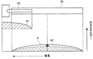
本実施の形態では、テールパイプ40の内部に上流開口端41aおよび下流開口端41bを有するインナーパイプ41を設け、インナーパイプ41の上流開口端41aをテールパイプ40の内部からテールパイプ40の上流開口端40aを通して外方に突出させて共鳴室38に連通させることにより、この上流開口端41aを共鳴室38を画成する消音器の壁部を構成するアウタシェル31、エンドプレート32および仕切板34によって囲まれる閉空間内に位置させているので、テールパイプ40内の排気ガスの圧力エネルギー、すなわち、空気の圧力エネルギーの圧力分布A1をインナーパイプ41および共鳴室38内に発生させることができる(図9参照)。
In the present embodiment, an
このため、この圧力エネルギーをインナーパイプ41および共鳴室38内に蓄積することができ、気柱共鳴時にこの圧力エネルギーをインナーパイプ41および共鳴室38内に保持して外部に放出させないようにすることができる
したがって、図9に示すように、テールパイプ40内の圧力エネルギーは、インナーパイプ41および共鳴室38内の圧力分布に応じた圧力エネルギーA1と、インナーパイプ41と共鳴室38とを除いたテールパイプ40の圧力分布に応じて圧力エネルギーA2とに分散することができ、インナーパイプ41および共鳴室38内を除いたテールパイプ40の圧力エネルギーのみを外部に放出することができる。For this reason, this pressure energy can be stored in the
すなわち、図10に示すように、テールパイプ40内の圧力エネルギーAからインナーパイプ41および共鳴室38内の圧力エネルギーA1(ハッチングで示す)を差し引いた残りの圧力エネルギーA2(ハッチングで示す)がテールパイプ40から外部に放出される。
That is, as shown in FIG. 10, the remaining pressure energy A2 (indicated by hatching) obtained by subtracting the pressure energy A1 (indicated by hatching) in the
気柱共鳴による音圧レベルは、圧力エネルギーによって決まるため、圧力エネルギーを少なくすることにより、すなわち、テールパイプ40の圧力エネルギーを圧力エネルギーA2のみとすることにより、音圧のピークをピークP1からピークP2(図8、図9参照)に下げて音圧レベルを低減することができる。
Since the sound pressure level due to the air column resonance is determined by the pressure energy, the peak of the sound pressure is peaked from the peak P1 by reducing the pressure energy, that is, by setting the pressure energy of the
また、インナーパイプ41および共鳴室38内は、圧力エネルギーを蓄積する容量が大きいため、テールパイプ40から放出される圧力エネルギーを大幅に低減することができる。したがって、気柱共鳴時の音圧のピークを下げて音圧レベルを低減することができ、排気騒音を低減することができる。
Moreover, since the capacity | capacitance which accumulate | stores pressure energy is large in the
一方、気柱共鳴時には、テールパイプ40内において上述したように排気脈動による音波(入射波と反射波)が開口端反射を繰り返すことにより定在波が発生し、テールパイプ40の管長L3と定在波の波長λとが特定の関係にあるとき、振幅が著しく大きくなり、気柱共鳴が生じる。On the other hand, at the time of air column resonance, the sound wave (incident wave and reflected wave) due to the exhaust pulsation is repeatedly reflected at the opening end in the
本実施の形態では、テールパイプ40の内部に、テールパイプ40の下流側に下流開口端41bが開口し、共鳴室38を画成する消音器の壁部を構成するアウタシェル31、エンドプレート32および仕切板34によって囲まれる閉空間内に位置する上流開口端41aを有するインナーパイプ41を設けたので、音波の伝搬方向にインナーパイプ41および共鳴室38を対向させることができるとともに、気柱共鳴の発生部位にインナーパイプ41の下流開口端41bを位置させることができる。
In the present embodiment, a downstream
このため、インナーパイプ41および共鳴室38を、気柱共鳴を音源とするヘルムホルツ共鳴室にすることができる。したがって、共鳴室38の共鳴周波数をテールパイプ40の気柱共鳴周波数と一致させることにより、気柱共鳴を抑制することができる。
For this reason, the
図11は、共鳴室38内に上流開口端41aが位置するインナーパイプ41を有するテールパイプ40を用いてスピーカ加振試験を行ったときの排気脈動の周波数と排気音の音圧レベル(dB)との測定結果を示す図である。
図11において、実線は、インナーパイプ41を有する本実施の形態のテールパイプ40を用いた測定結果を示し、破線は、インナーパイプを有していない従来のテールパイプを用いた測定結果を示している。FIG. 11 shows the frequency of the exhaust pulsation and the sound pressure level (dB) of the exhaust sound when the speaker excitation test is performed using the
In FIG. 11, the solid line shows the measurement result using the
本実施の形態では、音圧そのものを低減することができるため、図11に示すように、気柱共鳴時および気柱共鳴時以外の運転領域(周波数とエンジン21の回転数は対応している)に亘って音圧を低減することができるとともに、気柱共鳴時には音圧の低減に加えて、インナーパイプ41の長さL2に依存するヘルムホルツ共鳴を利用して気柱共鳴(一次成分f1、二次成分f2、三次成分f3)をより一層抑制することができる。このため、排気騒音を大幅に低減することができる。In the present embodiment, since the sound pressure itself can be reduced, as shown in FIG. 11, the operating region other than the time of air column resonance and the time other than the time of air column resonance (the frequency and the rotational speed of the
特に、図6に示すように、インナーパイプ41の下流開口端41bを、テールパイプ40の軸線方向長さの中央部よりも上流側に位置させることにより、気柱共鳴の定在波の音圧分布の高い位置、図6では、一次成分の音圧分布の腹a1の上流側の二次成分f2の音圧分布の腹a2に位置させることができ、ヘルムホルツ共鳴によって気柱共鳴をより一層抑制することができる。
In particular, as shown in FIG. 6, the downstream
また、本実施の形態では、気柱共鳴の発生領域にインナーパイプ41の下流開口端41bを位置させることができるため、減速時にマフラ27に導入される排気流量が急減した場合であっても、気柱共鳴を充分に抑制することができる。
Further, in the present embodiment, since the downstream opening
この結果、従来用いられていたサブマフラを廃止することができるとともにマフラ27を小型化することができるため、マフラ27の重量を低減することができるとともに、マフラ27の製造コストを低減することができる。
As a result, the conventionally used sub-muffler can be eliminated and the
なお、本実施の形態では、インナーパイプ41をマフラ27内に位置させているが、図12、図13に示すように、インナーパイプ41の下流端である下流開口端41cをマフラ27内からテールパイプ40の下流開口端40b側に延在させ、下流開口端41cを気柱共鳴の一次成分f1の音圧分布の腹a1と二次成分f2の音圧分布の腹a2の中間に位置させてもよい。
In the present embodiment, the
このようにすれば、気柱共鳴の一次成分f1と二次成分f2をヘルムホルツ共鳴によってより一層低減することができ、エンジン21の常用回転域でこもり音が発生するのをより一層抑制することができる。
In this way, the primary component f1 and the secondary component f2 of the air column resonance can be further reduced by the Helmholtz resonance, and the occurrence of a booming noise in the normal rotation region of the
このようにインナーパイプ41の下流開口端41cが気柱共鳴の一次成分f1の音圧分布の腹a1と二次成分f2の音圧分布の腹a2の中間に位置するように、インナーパイプ41をテールパイプ40内に設ける場合には、マフラ27の外方に位置するテールパイプ40の内周部に突出部42c、42dを設け、この突出部42c、42dによってインナーパイプ41をテールパイプ40に支持すればよい。
また、テールパイプ40の気柱共鳴周波数に共鳴室38の共鳴周波数を一致させるように、インナーパイプ41の長さと共鳴室38の容積Vを適宜設定すればよい。In this way, the
Further, the length of the
また、本実施の形態では、インナーパイプ41の上流部41Aの外周部を共鳴室38の仕切板34の内周部に支持するとともに、下流部41Bの円周方向の一部分である下流部41Bの上部および下部をテールパイプ40の突出部42a、42bを介してテールパイプ40の内周部に支持しているので、インナーパイプ41の上流部41Aと下流部41Bとをそれぞれ共鳴室38の仕切板34とテールパイプ40に両持ちで支持することができ、インナーパイプ41をテールパイプ40に強固に取付けることができる
また、本実施の形態では、単体のテールパイプ40をマフラ27に取付けているため、テールパイプ40の上流部をアウトレットパイプとして利用することができ、排気装置23の部品点数を削減して排気装置23の製造コストをより一層低減することができる。Further, in the present embodiment, the outer peripheral portion of the
(第2の実施の形態)
図14は、本発明に係る内燃機関の排気装置の第2の実施の形態を示す図であり、第1の実施の形態と同一の構成には同一の番号を付して説明を省略する。
図14において、マフラ27内にはアウターパイプ51が設けられており、このアウターパイプ51は、仕切板35およびエンドプレート33の挿通孔35c、33aに挿通され、拡張室36、37において仕切板35およびエンドプレート33によって支持されている。(Second Embodiment)
FIG. 14 is a diagram showing a second embodiment of the exhaust system for an internal combustion engine according to the present invention. The same components as those in the first embodiment are denoted by the same reference numerals and description thereof is omitted.
In FIG. 14, an
また、アウターパイプ51にはアウトレットパイプ52が設けられており、このアウトレットパイプ52は、仕切板34およびエンドプレート33の挿通孔34a、33aに挿通され、上流部52Aおよび下流部52Bが仕切板34およびエンドプレート33によって両持ちで支持されている。
The
また、中空部材としてのアウトレットパイプ52の下流部52Bにはテールパイプ53の上流部53Aが溶接等によって接続されており、アウトレットパイプ52の下流開口端52bがテールパイプ53の上流開口端53aよりも下流側に位置することにより、アウトレットパイプ52の下流開口端52bがテールパイプ53の上流部53Aに連通している。
Further, an
また、アウトレットパイプ52の下流部52Bには孔52cが形成されており、この孔52cは、アウターパイプ51の内周部とアウトレットパイプ52の外周部とによって画成される通路54とアウトレットパイプ52の内部とを連通している。
In addition, a
また、アウトレットパイプ52の上流部52Aの上流開口端52aは、アウターパイプ51の内部から外方に突出して共鳴室38に連通しており、アウトレットパイプ52は、上流開口端52aが共鳴室38を画成する消音器の壁部を構成するアウタシェル31、エンドプレート32および仕切板34によって囲まれる閉空間内に位置している。
The upstream
次に、作用を説明する。
マフラ27に導入される排気ガスは、インレットパイプ39の連通孔39b、39cを介して拡張室36、37に導入された後、アウターパイプ51の上流開口端51aからアウターパイプ51の内周部とアウトレットパイプ52の外周部とによって画成される通路54に導入される。Next, the operation will be described.
Exhaust gas introduced into the
この排気ガスは、アウトレットパイプ52の孔52cを通してアウトレットパイプ52に導入された後、テールパイプ53を通してテールパイプ53の下流部53Bの下流開口端53bから大気に排出される。
The exhaust gas is introduced into the
本実施の形態では、アウターパイプ51とテールパイプ53が排気ガスを排出する排気管を構成するようになっており、アウターパイプ51の上流部51Aが排気管の上流部を構成するとともに、アウターパイプ51の上流開口端51aが排気管の上流開口端を構成している。また、テールパイプ53の下流部53Bが排気管の下流部を構成するとともに、テールパイプ53の下流開口端53bが排気管の下流開口端を構成している。
In the present embodiment, the
そして、アウターパイプ51とテールパイプ53内にはアウターパイプ51とテールパイプ53の長さL3を半波長とした周波数を基本として、その半波長の自然数倍の波長の気柱共鳴が発生することになる。Then, as the fundamental frequency where the length L 3 of the
本実施の形態では、アウターパイプ51の内部に上流開口端52aおよび下流開口端52bを有するアウトレットパイプ52を設け、アウトレットパイプ52の上流開口端52aをアウターパイプ51の内部から外方に突出させて共鳴室38に連通させることにより、この上流開口端52aが共鳴室38を画成するマフラ27のアウタシェル31、エンドプレート32および仕切板34によって囲まれる閉空間内に位置されるので、アウターパイプ51およびテールパイプ53内の空気の圧力エネルギーの圧力分布をアウトレットパイプ52および共鳴室38内に発生させることができ、第1の実施の形態と同様に音圧そのものを低減することができる。
In the present embodiment, an
また、アウターパイプ51の内部に、テールパイプ53の下流側に下流開口端52bが開口し、共鳴室38内に位置する上流開口端52を有するアウトレットパイプ52を設けたので、音波の伝搬方向にアウトレットパイプ52および共鳴室38を対向させることができるとともに、気柱共鳴の発生部位にアウトレットパイプ52の下流開口端52bを位置させることができるため、アウトレットパイプ52および共鳴室38を、気柱共鳴を音源とするヘルムホルツ共鳴室にすることができる。このため、共鳴室38の共鳴周波数と一致させることにより、気柱共鳴を抑制することができる。
In addition, since the
なお、本実施の形態では、アウトレットパイプ52の下流部52Bに孔52cを有するので、この孔52cから上流開口端52aまでの間のアウトレットパイプ52の部位と共鳴室38とがヘルムホルツ共鳴室を構成することになる。このため、孔52cをアウトレットパイプ52の下流開口端52b側に近づけることにより、共鳴室38の共鳴周波数を低周波数側にチューニングすることができる。
In this embodiment, since the
このように本実施の形態では、音圧そのものを低減することができるため、第1の実施の形態と同様に、気柱共鳴時および気柱共鳴時以外の運転領域に亘って音圧を低減することができるとともに、気柱共鳴時には音圧の低減に加えて上流開口端52aから孔52cまでのアウトレットパイプ52の長さL2と共鳴室38の容積に依存するヘルムホルツ共鳴を利用して気柱共鳴をより一層抑制することができる。このため、排気騒音を大幅に低減することができる。Thus, in this embodiment, since the sound pressure itself can be reduced, the sound pressure is reduced over the operating region other than during air column resonance and during air column resonance, as in the first embodiment. it is possible to, at the time of air column resonance by utilizing the Helmholtz resonance that depends on the volume of length L 2 and the
また、気柱共鳴の発生領域にアウトレットパイプ52の下流開口端52bを位置させることができるため、減速時にマフラ27に導入される排気流量が急減した場合であっても、気柱共鳴を充分に抑制することができる。
Further, since the downstream opening
この結果、従来用いられていたサブマフラを廃止することができるとともにマフラ27を小型化することができるため、マフラ27の重量を低減することができるとともに、マフラ27の製造コストを低減することができる。
As a result, the conventionally used sub-muffler can be eliminated and the
また、本実施の形態では、マフラ27に既存のアウトレットパイプ52を中空部材として利用することにより、気柱共鳴をより一層抑制することができるため、マフラ27の製造コストが増大するのを抑制することができる。
Moreover, in this Embodiment, since the existing
(第3の実施の形態)
図15、図16は、本発明に係る内燃機関の排気装置の第3の実施の形態を示す図であり、第1の実施の形態と同一の構成には同一の番号を付して説明を省略する。
図16において、マフラ27内にはアウトレットパイプ61が設けられており、このアウトレットパイプ61は、仕切板34、35およびエンドプレート33の挿通孔34b、35c、33aに挿通され、拡張室36、37において仕切板34、35およびエンドプレート33によって支持されている。(Third embodiment)
FIGS. 15 and 16 are views showing a third embodiment of the exhaust system for an internal combustion engine according to the present invention. The same components as those in the first embodiment are denoted by the same reference numerals and described. Omitted.
In FIG. 16, an
また、アウトレットパイプ61の下流部61Bにはテールパイプ62の上流部62Aが溶接等によって接続されている。また、アウトレットパイプ61の上流部61Aには上流開口端としての孔61aが形成されており、マフラ27に導入された排気ガスは、孔61aを通してアウトレットパイプ61に導入されるようになっている。
An
また、図15、図16に示すように、アウトレットパイプ61の内部には平板状の仕切板63が設けられており、この仕切板63は、アウトレットパイプ61内をアウトレットパイプ61からテールパイプ62の上流開口端62aを通してテールパイプ62内に排気ガスを導入する排気通路65と、共鳴室38に連通する共鳴通路66とに区画している。
As shown in FIGS. 15 and 16, a
すなわち、排気通路65は、仕切板63の上面とアウトレットパイプ61の半環形状の上部半環部68の内周面によって画成される半円状の通路から構成されており、共鳴通路66は、仕切板63の下面とアウトレットパイプ61の半環形状の下部半環部69の内周面によって画成される半円状の通路から構成されている。
That is, the
また、アウトレットパイプ61の上流端には閉止板64が設けられており、アウトレットパイプ61の上流端は、閉止板64によって閉止されている。このため、アウトレットパイプ61の排気通路65と共鳴室38とは連通しないようになっている。
A closing
また、アウトレットパイプ61の下部半環部69の上流端69aは、仕切板63の上流端63aと共に共鳴室38内に延出して共鳴室38に連通することにより、共鳴通路66を構成する仕切板63および下部半環部69とが共鳴室38を画成するアウタシェル31、エンドプレート32および仕切板34によって囲まれる閉空間内に位置している。
Further, the
したがって、本実施の形態では、仕切板63と下部半環部69によって中空部材が構成されており、仕切板63の上流端63aと下部半環部69の上流端69aとによって上流端としての上流開口端70が構成され、仕切板63の下流端63bと仕切板63の下流端63bの直下の下部半環部69の部位とによって下流端としての下流開口端71が構成されることになる。
Therefore, in the present embodiment, the
次に、作用を説明する。
マフラ27に導入される排気ガスは、インレットパイプ39の連通孔39b、39cを介して拡張室36、37に導入された後、アウトレットパイプ61の孔61aから排気通路65に導入される。Next, the operation will be described.
The exhaust gas introduced into the
この排気ガスは、排気通路65からテールパイプ62の上流開口端62aを通してテールパイプ62内に導入され、テールパイプ62の下流開口端62bから大気に排出される。
The exhaust gas is introduced into the
本実施の形態では、アウトレットパイプ61とテールパイプ62とが排気ガスを排出する排気管を構成するようになっており、アウトレットパイプ61の上流部61Aが排気管の上流部を構成するとともに、アウトレットパイプ61の孔61aが排気管の上流開口端を構成している。
また、テールパイプ62の下流部62Bが排気管の下流部を構成するとともに、テールパイプ62の下流開口端62bが排気管の下流開口端を構成している。
そして、アウトレットパイプ61とテールパイプ62内には孔61aからテールパイプ62の下流開口端62bの長さL3を半波長とした周波数を基本として、その半波長の自然数倍の波長の気柱共鳴が発生することになる。In the present embodiment, the
Further, the
Then, as the fundamental frequency which is a half wavelength length L 3 of the downstream
本実施の形態では、アウトレットパイプ61の内部に、アウトレットパイプ61の下部半環部69と共に上流開口端70および下流開口端71を構成する仕切板63を設け、仕切板63の上流端63aと下部半環部69の上流端69aとを共鳴室38に連通させることにより、この仕切板63の上流端63aと下部半環部69の上流端69aとが共鳴室38を画成するアウタシェル31、エンドプレート32および仕切板34によって囲まれる閉空間内に位置させているので、アウトレットパイプ61およびテールパイプ62内の空気の圧力エネルギーの圧力分布を共鳴通路66および共鳴室38内に発生させることができ、第1の実施の形態と同様に音圧そのものを低減することができる。
In the present embodiment, a
また、インレットパイプ61の内部に、テールパイプ62の下流側に下流開口端71が開口し、共鳴室38によって上流開口端70が閉塞される仕切板63を設けたので、音波の伝搬方向に共鳴通路66および共鳴室38を対向させることができるとともに、気柱共鳴の発生部位に下流開口端71を位置させることができる。
このため、共鳴通路66および共鳴室38を、気柱共鳴を音源とするヘルムホルツ共鳴室にすることができる。したがって、共鳴室38の共鳴周波数を排気通路65およびテールパイプ62、すなわち、排気管の気柱共鳴周波数と一致させることにより、気柱共鳴を抑制することができる。In addition, since a
Therefore, the
このように本実施の形態では、音圧そのものを低減することができるため、第1の実施の形態と同様に、気柱共鳴時および気柱共鳴時以外の運転領域に亘って音圧を低減することができるとともに、気柱共鳴時には音圧の低減に加えて、下部半環部69と仕切板63の長さL2と共鳴室38の容積に依存するヘルムホルツ共鳴を利用して気柱共鳴をより一層抑制することができる。このため、排気騒音を大幅に低減することができる。Thus, in this embodiment, since the sound pressure itself can be reduced, the sound pressure is reduced over the operating region other than during air column resonance and during air column resonance, as in the first embodiment. it is possible to, in addition to the reduction of the sound pressure at the time of the air column resonance, use to air column resonance Helmholtz resonance that depends on the volume of length L 2 and the
また、気柱共鳴の発生領域に仕切板63の下流端63bとアウトレットパイプ61の下部半環部69とによって構成される下流開口端71を位置させることができるため、減速時にマフラ27に導入される排気流量が急減した場合であっても、気柱共鳴を充分に抑制することができる。
Further, since the downstream opening
この結果、従来用いられていたサブマフラを廃止することができるとともにマフラ27を小型化することができるため、マフラ27の重量を低減することができるとともに、マフラ27の製造コストを低減することができる。
As a result, the conventionally used sub-muffler can be eliminated and the
また、本実施の形態では、マフラ27に既存のアウトレットパイプ61に仕切板63を取付けることにより、アウトレットパイプ61を中空部材として利用して気柱共鳴をより一層抑制することができるため、マフラ27の製造コストが増大するのを抑制することができる。
In the present embodiment, by attaching the
(第4の実施の形態)
図17は、本発明に係る内燃機関の排気装置の第4の実施の形態を示す図であり、第1の実施の形態と同一の構成には同一の番号を付して説明を省略する。
図17において、消音器としてのマフラ81は、中空筒状に形成されたアウタシェル82と、アウタシェル82の両端を閉塞するエンドプレート83、84とを備えている。(Fourth embodiment)
FIG. 17 is a diagram showing a fourth embodiment of the exhaust device for an internal combustion engine according to the present invention. The same components as those in the first embodiment are denoted by the same reference numerals and description thereof is omitted.
In FIG. 17, a
アウタシェル82内には仕切板85が設けられており、この仕切板85によってアウタシェル82内は、排気ガスを拡張して消音するための拡張室86およびヘルムホルツ共鳴によって特定の周波数の排気音を消音するための共鳴室87に区画されている。
A
また、エンドプレート83および仕切板85にはそれぞれ挿通孔83a、85aが形成されており、この挿通孔83a、85aにはセンターパイプ26の下流側が接続されるインレットパイプ88が挿通されている。
Further, through
このインレットパイプ88は、拡張室86に収納されるようにしてエンドプレート83および仕切板85に支持されており、インレットパイプ88は、下流端が閉止されて共鳴室87と非連通状態となっている。
The
また、インレットパイプ88にはインレットパイプ88の軸線方向(排気流の排気方向)および周方向に複数の小孔88aが形成されており、インレットパイプ88の内部と拡張室86とは、小孔88aを介して連通している。したがって、センターパイプ26からインレットパイプ88を通してマフラ81に導入される排気ガスは、小孔88aを介して拡張室86に導入されるようになっている。
The
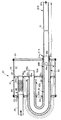
また、エンドプレート83、84および仕切板85にはそれぞれ挿通孔83b、83c、84a、85b、85cが形成されており、挿通孔85b、83b、83c、85c、84aには湾曲形状を有する中空部材としてのアウトレットパイプ89が挿通され、このアウトレットパイプ89は、エンドプレート83および仕切板85に支持されている。
The
また、挿通孔83b、83c、85c、84aには湾曲形状を有するアウターパイプ90が挿通されており、このアウターパイプ90は、内部にアウトレットパイプ89が収納され、エンドプレート83、84および仕切板85に支持されている。
Further, an
アウトレットパイプ89の下流部89Bにはテールパイプ91の上流部91Aが溶接等によって接続されており、アウトレットパイプ89の下流開口端89bがテールパイプ91の上流開口端91aよりも下流側に位置することにより、アウトレットパイプ89の下流開口端89bがテールパイプ91の上流部91Aに連通している。
The upstream portion 91A of the
また、アウトレットパイプ89の下流部89Bには孔89cが形成されており、この孔89cは、アウターパイプ90の内周部とアウトレットパイプ89の外周部とによって画成される通路92とアウトレットパイプ89の内部とを連通している。
In addition, a
また、アウトレットパイプ89の上流端としての上流開口端89aは、アウターパイプ90の内部から外方に突出して共鳴室87に連通しており、アウトレットパイプ89は、上流開口端89aが共鳴室87を画成する消音器の壁部を構成するアウタシェル82、エンドプレート84および仕切板85によって囲まれる閉空間内に位置している。
Further, an upstream
次に、作用を説明する。
マフラ81に導入される排気ガスは、インレットパイプ88の連通孔88aを介して拡張室86に導入された後、アウターパイプ90の上流開口端90aからアウターパイプ90の内周部とアウトレットパイプ89の外周部とによって画成される通路92に導入される。Next, the operation will be described.
The exhaust gas introduced into the
この排気ガスは、アウトレットパイプ89の孔89cを通してアウトレットパイプ89に導入された後、テールパイプ91を通してテールパイプ91の下流開口端91bから大気に排出される。
The exhaust gas is introduced into the
本実施の形態では、アウターパイプ90とテールパイプ91とが排気ガスを排出する排気管を構成するようになっており、アウターパイプ90の上流部90Aが排気管の上流部を構成するとともに、アウターパイプ90の上流開口端90aが排気管の上流開口端を構成している。
In the present embodiment, the
また、テールパイプ91の下流部91Bが排気管の下流部を構成し、テールパイプ91の下流開口端91bが排気管の下流開口端を構成している。
そして、アウターパイプ90とテールパイプ91内にはアウターパイプ90とテールパイプ91の長さL3を半波長とした周波数を基本として、その半波長の自然数倍の波長の気柱共鳴が発生することになる。Further, the
Then, as the fundamental frequency where the length L 3 of the
本実施の形態では、アウターパイプ90の内部に上流開口端89aおよび下流端としての下流開口端89bを有するアウトレットパイプ89を設け、アウトレットパイプ89の上流開口端89aをアウターパイプ90の内部から外方に突出させて共鳴室87に連通させることにより、上流開口端89aが共鳴室87を画成するアウタシェル82、エンドプレート83および仕切板85によって囲まれる閉空間内に位置されるので、アウターパイプ90およびテールパイプ91内の空気の圧力エネルギーの圧力分布をアウトレットパイプ89および共鳴室87内に発生させることができ、第1の実施の形態と同様に音圧そのものを低減することができる。
In the present embodiment, an
また、アウターパイプ90の内部に、テールパイプ91の下流側に下流開口端89bが開口し、共鳴室87内に位置する上流開口端89aを有するアウトレットパイプ89を設けたので、音波の伝搬方向にアウトレットパイプ89および共鳴室87を対向させることができるとともに、気柱共鳴の発生部位にアウトレットパイプ89の下流開口端89bを位置させることができるため、アウトレットパイプ89および共鳴室87を、気柱共鳴を音源とするヘルムホルツ共鳴室にすることができる。
このため、共鳴室87の共鳴周波数をアウターパイプ90およびテールパイプ91の気柱共鳴周波数と一致させることにより、気柱共鳴を抑制することができる。
なお、本実施の形態では、アウトレットパイプ89が下流部89Bに孔89cを有するので、この孔89cから上流端89aまでの間のアウトレットパイプ89の部位と共鳴室87とがヘルムホルツ共鳴室を構成することになる。このため、孔89cをアウトレットパイプ89の下流開口端89b側に近づけることにより、共鳴室87の共鳴周波数を低周波数側にチューニングすることができる。In addition, since the
For this reason, air column resonance can be suppressed by making the resonance frequency of the
In this embodiment, since the
このように本実施の形態では、音圧そのものを低減することができるため、第1の実施の形態と同様に、気柱共鳴時および気柱共鳴時以外の運転領域に亘って音圧を低減することができるとともに、気柱共鳴時には音圧の低減に加えて、上流端89aから孔89cまでのアウトレットパイプ89の長さL2と共鳴室87の容積に依存するヘルムホルツ共鳴を利用して気柱共鳴をより一層抑制することができる。このため、排気騒音を大幅に低減することができる。Thus, in this embodiment, since the sound pressure itself can be reduced, the sound pressure is reduced over the operating region other than during air column resonance and during air column resonance, as in the first embodiment. it is possible to, at the time of the air column resonance in addition to the reduction of sound pressure, by utilizing the Helmholtz resonance that depends on the volume of length L 2 and the
また、気柱共鳴の発生領域にアウトレットパイプ89の下流開口端89bを位置させることができるため、減速時にマフラ81に導入される排気流量が急減した場合であっても、気柱共鳴を充分に抑制することができる。
Further, since the downstream opening
この結果、従来用いられていたサブマフラを廃止することができるとともにマフラ81を小型化することができるため、マフラ81の重量を低減することができるとともに、マフラ81の製造コストを低減することができる。
As a result, the conventionally used sub-muffler can be eliminated and the
また、本実施の形態では、アウトレットパイプ89およびアウターパイプ90を湾曲させているので、マフラ81内でアウトレットパイプ89を長くすることができ、マフラ81の軸線方向長さを短くして共鳴室87の共鳴周波数を低周波数側にチューニングすることができる。
Further, in the present embodiment, since the
また、今回開示された実施の形態は、全ての点で例示であってこの実施の形態に制限されるものではない。本発明の範囲は、上記した実施の形態のみの説明ではなくて請求の範囲によって示され、請求の範囲と均等の意味および範囲内での全ての変更が含まれることが意図される。 The embodiment disclosed this time is illustrative in all respects and is not limited to this embodiment. The scope of the present invention is shown not by the above description of the embodiments but by the scope of the claims, and is intended to include meanings equivalent to the scope of the claims and all modifications within the scope.
以上のように、本発明に係る内燃機関の排気装置は、従来用いられていたサブマフラを廃止して排気騒音を低減することができ、排気装置の重量を低減することができるとともに、排気装置の製造コストを低減することができるという効果を有し、排気流の排気方向の最下流に設けられた排気管の気柱共鳴による排気騒音を低減するようにした内燃機関の排気装置等として有用である。 As described above, the exhaust device for an internal combustion engine according to the present invention can reduce the exhaust noise by eliminating the conventionally used sub-muffler, and can reduce the weight of the exhaust device. It has the effect of reducing the manufacturing cost, and is useful as an exhaust system for an internal combustion engine that reduces exhaust noise due to air column resonance of an exhaust pipe provided at the most downstream in the exhaust direction of the exhaust flow. is there.
21 エンジン(内燃機関)
23 排気装置
27、81 マフラ(消音器)
31、82 アウタシェル(消音器の壁部)
32、84 エンドプレート(消音器の壁部)
34、85 仕切板(消音器の壁部)
38、87 共鳴室
40 テールパイプ(排気管)
40A 上流部
40B 下流部
40a 上流開口端
40b 下流開口端
41 インナーパイプ(中空部材)
41A 上流部
41B 下流部
41a 上流開口端(上流端)
41b、41c 下流開口端(下流端)
41c 下流開口端(下流端)
51 アウターパイプ(排気管)
51a 上流開口端(排気管の上流開口端)
52 アウトレットパイプ(中空部材)
52A 上流部(排気管の上流部)
52a 上流開口端(排気管の上流開口端)
52a 上流開口端(上流端)
52b 下流開口端(下流端)
53 テールパイプ(排気管)
53B 下流部(排気管の下流部)
53b 下流開口端(排気管の下流開口端)
61 アウトレットパイプ(排気管)
61A 上流部(排気管の上流部)
61a 孔(排気管の上流開口端)
62 テールパイプ(排気管)
62B 下流部(排気管の下流部)
62b 下流開口端(排気管の下流開口端)
63 仕切板(中空部材)
69 下部半環部(中空部材)
70 上流開口端(上流端)
71 下流開口端(下流端)
89 アウトレットパイプ(中空部材)
89a 上流開口端(上流端)
89b 下流開口端(下流端)
90 アウターパイプ(排気管)
90A 上流部(排気管の上流部)
90a 上流開口端(排気管の上流開口端)
91 テールパイプ(排気管)
91B 下流部(排気管の下流部)
91b 下流開口端(排気管の下流開口端)21 Engine (Internal combustion engine)
23
31, 82 Outer shell (wall of silencer)
32, 84 End plate (muffler wall)
34, 85 Partition plate (wall of silencer)
38, 87
40A
41A
41b, 41c Downstream opening end (downstream end)
41c downstream opening end (downstream end)
51 Outer pipe (exhaust pipe)
51a Upstream opening end (upstream opening end of exhaust pipe)
52 Outlet pipe (hollow member)
52A upstream part (upstream part of exhaust pipe)
52a Upstream opening end (upstream opening end of exhaust pipe)
52a Upstream open end (upstream end)
52b Downstream end (downstream end)
53 Tail pipe (exhaust pipe)
53B Downstream part (downstream part of exhaust pipe)
53b Downstream open end (downstream open end of exhaust pipe)
61 Outlet pipe (exhaust pipe)
61A Upstream part (upstream part of exhaust pipe)
61a hole (upstream open end of exhaust pipe)
62 Tail pipe (exhaust pipe)
62B Downstream part (downstream part of exhaust pipe)
62b Downstream open end (downstream open end of exhaust pipe)
63 Partition plate (hollow member)
69 Lower half ring (hollow member)
70 Upstream open end (upstream end)
71 Downstream open end (downstream end)
89 Outlet pipe (hollow member)
89a Upstream open end (upstream end)
89b Downstream open end (downstream end)
90 Outer pipe (exhaust pipe)
90A upstream part (upstream part of exhaust pipe)
90a Upstream opening end (upstream opening end of exhaust pipe)
91 Tail pipe (exhaust pipe)
91B Downstream part (downstream part of exhaust pipe)
91b Downstream open end (downstream open end of exhaust pipe)
Claims (4)
前記排気管の内部に中空部材を設け、前記中空部材は、下流端が開口端を構成し、開口端を構成する上流端が前記排気管の内部から前記排気管の前記上流開口端を通して外方に突出して前記共鳴室に連通することにより、前記共鳴室を画成する前記消音器の壁部によって囲まれる閉空間内に位置し、
前記排気管は、前記消音器の内部に設けられたアウターパイプと、前記アウターパイプに接続され、前記アウターパイプから前記消音器の下流側に延在するテールパイプとから構成され、前記中空部材は、前記アウターパイプの内部に設けられたアウトレットパイプから構成され、
前記アウトレットパイプの下流部は、前記テールパイプの上流部に接続されるとともに、前記アウトレットパイプの下流部に前記アウトレットパイプの内部と前記アウターパイプの内部とを連通する孔が形成されることを特徴とする内燃機関の排気装置。 Exhaust stream discharged from the internal combustion engine is introduced, adjacent to the expansion chamber and the expansion chamber for muffling by expanding the exhaust flow, a muffler having a resonance chamber for muffling the exhaust sound of a specific frequency, the exhaust It has an upstream opening end connected to the expansion chamber of the silencer at the upstream portion in the exhaust direction of the flow, and a downstream opening end for discharging the exhaust flow discharged from the silencer to the atmosphere at the downstream portion An exhaust system for an internal combustion engine comprising an exhaust pipe,
A hollow member is provided inside the exhaust pipe, and the hollow member has an open end at the downstream end, and an upstream end constituting the open end is outward from the inside of the exhaust pipe through the upstream open end of the exhaust pipe. Is located in a closed space surrounded by the wall of the silencer that defines the resonance chamber by projecting to the resonance chamber ,
The exhaust pipe is composed of an outer pipe provided inside the silencer, and a tail pipe connected to the outer pipe and extending from the outer pipe to the downstream side of the silencer. The outlet pipe provided inside the outer pipe,
The downstream part of the outlet pipe is connected to the upstream part of the tail pipe, and the downstream part of the outlet pipe is formed with a hole that communicates the inside of the outlet pipe and the inside of the outer pipe. An exhaust system for an internal combustion engine.
Applications Claiming Priority (1)
| Application Number | Priority Date | Filing Date | Title |
|---|---|---|---|
| PCT/JP2009/007324 WO2011080793A1 (en) | 2009-12-28 | 2009-12-28 | Exhaust apparatus for internal combustion engine |
Publications (2)
| Publication Number | Publication Date |
|---|---|
| JPWO2011080793A1 JPWO2011080793A1 (en) | 2013-05-09 |
| JP5472321B2 true JP5472321B2 (en) | 2014-04-16 |
Family
ID=44226229
Family Applications (1)
| Application Number | Title | Priority Date | Filing Date |
|---|---|---|---|
| JP2011547089A Expired - Fee Related JP5472321B2 (en) | 2009-12-28 | 2009-12-28 | Exhaust device for internal combustion engine |
Country Status (5)
| Country | Link |
|---|---|
| US (1) | US8607923B2 (en) |
| EP (1) | EP2520775B1 (en) |
| JP (1) | JP5472321B2 (en) |
| CN (1) | CN102686840A (en) |
| WO (1) | WO2011080793A1 (en) |
Cited By (2)
| Publication number | Priority date | Publication date | Assignee | Title |
|---|---|---|---|---|
| CN104033226A (en) * | 2014-07-01 | 2014-09-10 | 居国文 | Silencer |
| CN104088686A (en) * | 2014-07-01 | 2014-10-08 | 居国文 | Miniature silencer |
Families Citing this family (32)
| Publication number | Priority date | Publication date | Assignee | Title |
|---|---|---|---|---|
| JP2013528518A (en) * | 2010-04-29 | 2013-07-11 | フィスカー オートモーティブ インコーポレイテッド | Front exhaust system |
| JP5771113B2 (en) * | 2011-10-06 | 2015-08-26 | 川崎重工業株式会社 | Exhaust silencer |
| KR101315266B1 (en) * | 2012-02-24 | 2013-10-08 | 세종공업 주식회사 | Tail pipe structure for muffuler |
| JP6162407B2 (en) * | 2013-01-11 | 2017-07-12 | フタバ産業株式会社 | Silencer |
| WO2014141778A1 (en) | 2013-03-11 | 2014-09-18 | フタバ産業株式会社 | Exhaust pipe |
| DE102014103054A1 (en) | 2014-03-07 | 2015-09-10 | Tenneco Gmbh | exhaust silencer |
| US9890952B2 (en) * | 2014-04-25 | 2018-02-13 | Noritz Corporation | Exhaust structure for combustion apparatus and construction method thereof |
| DE102014107907A1 (en) * | 2014-06-04 | 2015-12-17 | Eberspächer Exhaust Technology GmbH & Co. KG | silencer |
| EP3237094B1 (en) * | 2014-12-22 | 2021-07-07 | Donaldson Filtration Deutschland GmbH | Device for attenuating an exhaust-gas noise, system comprising a device of said type, sorption dryer having a device of said type, and method for attenuating an exhaust-gas noise |
| JP5945018B1 (en) * | 2015-01-30 | 2016-07-05 | 本田技研工業株式会社 | Exhaust muffler |
| JP6059749B2 (en) * | 2015-02-23 | 2017-01-11 | 本田技研工業株式会社 | Exhaust muffler |
| DE102015223680A1 (en) * | 2015-11-30 | 2017-06-01 | Eberspächer Exhaust Technology GmbH & Co. KG | silencer |
| WO2017126083A1 (en) | 2016-01-21 | 2017-07-27 | フタバ産業株式会社 | Muffler |
| US10513956B2 (en) * | 2016-07-28 | 2019-12-24 | Tarkan FAHRI | Muffler assembly |
| IT201600110831A1 (en) * | 2016-11-04 | 2018-05-04 | Piaggio & C Spa | EXHAUST TERMINAL FOR MOTOR VEHICLES |
| CN106481422A (en) * | 2016-11-15 | 2017-03-08 | 安徽江淮汽车集团股份有限公司 | Exhaust silencer assembly |
| DE102017109191A1 (en) * | 2017-04-28 | 2018-10-31 | Faurecia Emissions Control Technologies, Germany Gmbh | Component of an exhaust system and method for producing such a component |
| CN107218105A (en) * | 2017-07-28 | 2017-09-29 | 安徽江淮汽车集团股份有限公司 | A kind of muffler pipe line structure and silencer |
| US10900396B2 (en) * | 2018-01-15 | 2021-01-26 | Ford Global Technologies, Llc | Exhaust orifice tube for vehicle mufflers |
| DE102019101418A1 (en) * | 2018-01-26 | 2019-08-01 | Futaba Industrial Co., Ltd. | silencer |
| JP6557372B1 (en) * | 2018-02-15 | 2019-08-07 | 本田技研工業株式会社 | Silencer unit |
| WO2020031212A1 (en) * | 2018-08-10 | 2020-02-13 | Hero MotoCorp Limited | Exhaust system |
| RU2697205C1 (en) * | 2018-10-15 | 2019-08-13 | федеральное государственное бюджетное образовательное учреждение высшего образования "Алтайский государственный технический университет им. И.И. Ползунова" (АлтГТУ) | Internal combustion engine exhaust noise silencer |
| RU2697207C1 (en) * | 2018-10-18 | 2019-08-13 | федеральное государственное бюджетное образовательное учреждение высшего образования "Алтайский государственный технический университет им. И.И. Ползунова" (АлтГТУ) | Internal combustion engine exhaust noise silencer |
| CN109209567B (en) * | 2018-11-06 | 2020-09-08 | 广州汽车集团股份有限公司 | Exhaust system silencer and car |
| JP6936262B2 (en) * | 2019-01-28 | 2021-09-15 | フタバ産業株式会社 | Silencer |
| US11421569B2 (en) | 2019-10-18 | 2022-08-23 | Tenneco Automotive Operating Company Inc. | Muffler |
| RU195483U1 (en) * | 2019-11-25 | 2020-01-29 | Общество С Ограниченной Ответственностью "Феникс" | Muffler |
| JP2021116732A (en) * | 2020-01-24 | 2021-08-10 | フタバ産業株式会社 | Muffler |
| JP2022095467A (en) * | 2020-12-16 | 2022-06-28 | フタバ産業株式会社 | Exhaust pipe |
| JP7488790B2 (en) | 2021-05-18 | 2024-05-22 | 中央精機株式会社 | Vehicle Wheels |
| DE102022131738A1 (en) * | 2022-11-30 | 2024-06-06 | Hug Engineering Ag | Silencer for an exhaust system |
Citations (2)
| Publication number | Priority date | Publication date | Assignee | Title |
|---|---|---|---|---|
| JPS54143941U (en) * | 1978-03-30 | 1979-10-05 | ||
| JPH1030424A (en) * | 1996-05-16 | 1998-02-03 | Nissan Motor Co Ltd | Automotive exhaust silencer |
Family Cites Families (23)
| Publication number | Priority date | Publication date | Assignee | Title |
|---|---|---|---|---|
| IT1044068B (en) * | 1974-11-12 | 1980-03-20 | Renault | COMBUSTIONS ENGINE SILENCER |
| US4102430A (en) * | 1977-08-11 | 1978-07-25 | Tenneco, Inc. | Peripheral return flow muffler |
| JPS587049Y2 (en) * | 1978-07-24 | 1983-02-07 | カルソニックカンセイ株式会社 | muffler |
| US4501341A (en) * | 1981-03-12 | 1985-02-26 | Jones Adrian D | Low frequency muffler |
| JPS58193007U (en) * | 1982-06-21 | 1983-12-22 | 日産自動車株式会社 | Silencer |
| JPS5932111U (en) * | 1982-08-25 | 1984-02-28 | 日産自動車株式会社 | automotive muffler |
| JPS60128924U (en) * | 1984-02-08 | 1985-08-29 | 株式会社 三五 | Silencer for internal combustion engines |
| JPS60175718A (en) * | 1984-02-22 | 1985-09-09 | Nippon Soken Inc | Muffler for internal combustion engine |
| JPS61142114U (en) * | 1985-02-25 | 1986-09-02 | ||
| JPS61142114A (en) | 1985-05-09 | 1986-06-30 | 株式会社 フジパツクシステム | Article carrying-out device in packaging machine |
| JPH0367012A (en) * | 1989-08-04 | 1991-03-22 | Suzuki Motor Corp | Exhaust silencer of engine |
| JPH09304084A (en) | 1996-05-09 | 1997-11-28 | Matsushita Electric Ind Co Ltd | Location registration device for mobile |
| KR100306339B1 (en) * | 1999-02-05 | 2001-09-13 | 이옥노 | Muffler for internal combustion engine |
| JP4392592B2 (en) * | 2003-12-12 | 2010-01-06 | トヨタ自動車株式会社 | Exhaust silencer |
| JP2005256736A (en) | 2004-03-11 | 2005-09-22 | Calsonic Kansei Corp | Resonator structure for automobile |
| JP4759700B2 (en) | 2004-08-02 | 2011-08-31 | トヨタ自動車株式会社 | Exhaust structure |
| JP4577282B2 (en) * | 2006-08-11 | 2010-11-10 | トヨタ自動車株式会社 | Engine exhaust device, manufacturing method thereof, muffler and vehicle |
| JP2009236040A (en) | 2008-03-27 | 2009-10-15 | Toyota Motor Corp | Exhaust muffler |
| JP5205321B2 (en) | 2009-03-26 | 2013-06-05 | 本田技研工業株式会社 | Air conditioner for vehicles |
| WO2011024234A1 (en) * | 2009-08-28 | 2011-03-03 | トヨタ自動車株式会社 | Exhaust device for internal combustion engine |
| US8806859B2 (en) * | 2009-08-28 | 2014-08-19 | Toyota Jidosha Kabushiki Kaisha | Exhaust gas apparatus of an internal combustion engine |
| BR112012007406A2 (en) * | 2009-09-24 | 2016-12-06 | Toyota Motor Co Ltd | exhaust pipe part and exhaust system for internal combustion engines. |
| CN102782266B (en) * | 2009-11-09 | 2014-04-02 | 丰田自动车株式会社 | Exhaust device of internal combustion engine |
-
2009
- 2009-12-28 US US13/517,198 patent/US8607923B2/en not_active Expired - Fee Related
- 2009-12-28 WO PCT/JP2009/007324 patent/WO2011080793A1/en not_active Ceased
- 2009-12-28 JP JP2011547089A patent/JP5472321B2/en not_active Expired - Fee Related
- 2009-12-28 EP EP09852775.7A patent/EP2520775B1/en not_active Not-in-force
- 2009-12-28 CN CN2009801631906A patent/CN102686840A/en active Pending
Patent Citations (2)
| Publication number | Priority date | Publication date | Assignee | Title |
|---|---|---|---|---|
| JPS54143941U (en) * | 1978-03-30 | 1979-10-05 | ||
| JPH1030424A (en) * | 1996-05-16 | 1998-02-03 | Nissan Motor Co Ltd | Automotive exhaust silencer |
Cited By (2)
| Publication number | Priority date | Publication date | Assignee | Title |
|---|---|---|---|---|
| CN104033226A (en) * | 2014-07-01 | 2014-09-10 | 居国文 | Silencer |
| CN104088686A (en) * | 2014-07-01 | 2014-10-08 | 居国文 | Miniature silencer |
Also Published As
| Publication number | Publication date |
|---|---|
| US8607923B2 (en) | 2013-12-17 |
| JPWO2011080793A1 (en) | 2013-05-09 |
| EP2520775A1 (en) | 2012-11-07 |
| CN102686840A (en) | 2012-09-19 |
| EP2520775A4 (en) | 2014-11-12 |
| US20120273302A1 (en) | 2012-11-01 |
| WO2011080793A1 (en) | 2011-07-07 |
| EP2520775B1 (en) | 2016-04-06 |
Similar Documents
| Publication | Publication Date | Title |
|---|---|---|
| JP5472321B2 (en) | Exhaust device for internal combustion engine | |
| JP5257517B2 (en) | Exhaust device for internal combustion engine | |
| JP5298202B2 (en) | Exhaust device for internal combustion engine | |
| JP5229391B2 (en) | Exhaust device for internal combustion engine | |
| JP5282825B2 (en) | Exhaust pipe parts and exhaust system for internal combustion engine | |
| CN103270260B (en) | Silencer for vehicles | |
| JP2002054421A (en) | Low cost muffler | |
| JP2002235522A (en) | Exhaust silencer | |
| JP2011027038A (en) | Muffler | |
| JP4573463B2 (en) | Muffler for internal combustion engine | |
| JP2006207378A (en) | Noise reduction device for exhaust system and exhaust system having the same | |
| JP5119230B2 (en) | Exhaust device for internal combustion engine | |
| JP4339070B2 (en) | Exhaust purification equipment | |
| KR101693887B1 (en) | Muffler with multi-resonator for construction equipment | |
| JP2000227019A (en) | Exhaust silencer and communication pipe for exhaust silencer | |
| JP2005069191A (en) | Exhaust device | |
| JP2006283625A (en) | High frequency sound reduction silencer | |
| JP5067411B2 (en) | Exhaust device for internal combustion engine | |
| CN103026015B (en) | The silencer of vehicle | |
| JP2012087731A (en) | Exhaust device | |
| JP2004137951A (en) | Resonance type silencer | |
| JP2011069244A (en) | Exhaust pipe part and exhaust device of internal combustion engine | |
| JP6018013B2 (en) | Silencer | |
| JP2009191618A (en) | Silencer | |
| JP2002021549A (en) | Silencer |
Legal Events
| Date | Code | Title | Description |
|---|---|---|---|
| A131 | Notification of reasons for refusal |
Free format text: JAPANESE INTERMEDIATE CODE: A131 Effective date: 20130702 |
|
| A521 | Request for written amendment filed |
Free format text: JAPANESE INTERMEDIATE CODE: A523 Effective date: 20130718 |
|
| TRDD | Decision of grant or rejection written | ||
| A01 | Written decision to grant a patent or to grant a registration (utility model) |
Free format text: JAPANESE INTERMEDIATE CODE: A01 Effective date: 20140107 |
|
| A61 | First payment of annual fees (during grant procedure) |
Free format text: JAPANESE INTERMEDIATE CODE: A61 Effective date: 20140120 |
|
| LAPS | Cancellation because of no payment of annual fees |