JP5460643B2 - Manufacturing method of plugged honeycomb structure and plugging filling jig - Google Patents
Manufacturing method of plugged honeycomb structure and plugging filling jig Download PDFInfo
- Publication number
- JP5460643B2 JP5460643B2 JP2011095858A JP2011095858A JP5460643B2 JP 5460643 B2 JP5460643 B2 JP 5460643B2 JP 2011095858 A JP2011095858 A JP 2011095858A JP 2011095858 A JP2011095858 A JP 2011095858A JP 5460643 B2 JP5460643 B2 JP 5460643B2
- Authority
- JP
- Japan
- Prior art keywords
- honeycomb structure
- plugged
- plugging
- cells
- ceramic slurry
- Prior art date
- Legal status (The legal status is an assumption and is not a legal conclusion. Google has not performed a legal analysis and makes no representation as to the accuracy of the status listed.)
- Active
Links
- 238000011049 filling Methods 0.000 title claims description 115
- 238000004519 manufacturing process Methods 0.000 title claims description 90
- 239000002002 slurry Substances 0.000 claims description 130
- 239000000919 ceramic Substances 0.000 claims description 125
- 238000000034 method Methods 0.000 claims description 70
- 230000002093 peripheral effect Effects 0.000 claims description 38
- 238000005192 partition Methods 0.000 claims description 34
- 238000003825 pressing Methods 0.000 claims description 11
- 239000012530 fluid Substances 0.000 claims description 10
- 229920001971 elastomer Polymers 0.000 description 20
- 239000005060 rubber Substances 0.000 description 20
- 239000000463 material Substances 0.000 description 9
- 238000007796 conventional method Methods 0.000 description 7
- 230000000052 comparative effect Effects 0.000 description 6
- 229920001577 copolymer Polymers 0.000 description 6
- 229920003244 diene elastomer Polymers 0.000 description 6
- 238000002485 combustion reaction Methods 0.000 description 5
- 238000010586 diagram Methods 0.000 description 5
- 238000001035 drying Methods 0.000 description 5
- 230000002463 transducing effect Effects 0.000 description 5
- 239000002390 adhesive tape Substances 0.000 description 4
- 239000000956 alloy Substances 0.000 description 4
- 229910045601 alloy Inorganic materials 0.000 description 4
- 229910052878 cordierite Inorganic materials 0.000 description 4
- JSKIRARMQDRGJZ-UHFFFAOYSA-N dimagnesium dioxido-bis[(1-oxido-3-oxo-2,4,6,8,9-pentaoxa-1,3-disila-5,7-dialuminabicyclo[3.3.1]nonan-7-yl)oxy]silane Chemical compound [Mg++].[Mg++].[O-][Si]([O-])(O[Al]1O[Al]2O[Si](=O)O[Si]([O-])(O1)O2)O[Al]1O[Al]2O[Si](=O)O[Si]([O-])(O1)O2 JSKIRARMQDRGJZ-UHFFFAOYSA-N 0.000 description 4
- 230000004927 fusion Effects 0.000 description 4
- 239000002184 metal Substances 0.000 description 4
- -1 polyethylene Polymers 0.000 description 4
- 239000011347 resin Substances 0.000 description 4
- 229920005989 resin Polymers 0.000 description 4
- 239000004709 Chlorinated polyethylene Substances 0.000 description 3
- 229920000089 Cyclic olefin copolymer Polymers 0.000 description 3
- YCKRFDGAMUMZLT-UHFFFAOYSA-N Fluorine atom Chemical compound [F] YCKRFDGAMUMZLT-UHFFFAOYSA-N 0.000 description 3
- 239000005062 Polybutadiene Substances 0.000 description 3
- 229920006311 Urethane elastomer Polymers 0.000 description 3
- 229920000800 acrylic rubber Polymers 0.000 description 3
- 239000004927 clay Substances 0.000 description 3
- 239000011737 fluorine Substances 0.000 description 3
- 229910052731 fluorine Inorganic materials 0.000 description 3
- 229920005555 halobutyl Polymers 0.000 description 3
- 229920003049 isoprene rubber Polymers 0.000 description 3
- CLNYHERYALISIR-UHFFFAOYSA-N nona-1,3-diene Chemical compound CCCCCC=CC=C CLNYHERYALISIR-UHFFFAOYSA-N 0.000 description 3
- 229920001084 poly(chloroprene) Polymers 0.000 description 3
- 229920000058 polyacrylate Polymers 0.000 description 3
- 229920002857 polybutadiene Polymers 0.000 description 3
- 239000000843 powder Substances 0.000 description 3
- 229920002379 silicone rubber Polymers 0.000 description 3
- 238000000638 solvent extraction Methods 0.000 description 3
- 229920003048 styrene butadiene rubber Polymers 0.000 description 3
- 239000004711 α-olefin Substances 0.000 description 3
- 239000004698 Polyethylene Substances 0.000 description 2
- 239000004743 Polypropylene Substances 0.000 description 2
- 235000009508 confectionery Nutrition 0.000 description 2
- 238000010304 firing Methods 0.000 description 2
- 239000002655 kraft paper Substances 0.000 description 2
- 229920000573 polyethylene Polymers 0.000 description 2
- 229920001155 polypropylene Polymers 0.000 description 2
- 239000011148 porous material Substances 0.000 description 2
- 238000012545 processing Methods 0.000 description 2
- 239000010935 stainless steel Substances 0.000 description 2
- 229910001220 stainless steel Inorganic materials 0.000 description 2
- 244000043261 Hevea brasiliensis Species 0.000 description 1
- 239000004820 Pressure-sensitive adhesive Substances 0.000 description 1
- 239000000853 adhesive Substances 0.000 description 1
- 230000001070 adhesive effect Effects 0.000 description 1
- 239000011230 binding agent Substances 0.000 description 1
- 239000002612 dispersion medium Substances 0.000 description 1
- 230000000694 effects Effects 0.000 description 1
- 238000003912 environmental pollution Methods 0.000 description 1
- 238000001125 extrusion Methods 0.000 description 1
- 238000012423 maintenance Methods 0.000 description 1
- 239000000203 mixture Substances 0.000 description 1
- 238000012986 modification Methods 0.000 description 1
- 230000004048 modification Effects 0.000 description 1
- 238000000465 moulding Methods 0.000 description 1
- 229920003052 natural elastomer Polymers 0.000 description 1
- 229920001194 natural rubber Polymers 0.000 description 1
- 239000013618 particulate matter Substances 0.000 description 1
- 238000004080 punching Methods 0.000 description 1
- 238000000746 purification Methods 0.000 description 1
- 230000003014 reinforcing effect Effects 0.000 description 1
- 238000007789 sealing Methods 0.000 description 1
- 239000000779 smoke Substances 0.000 description 1
- 239000004071 soot Substances 0.000 description 1
Images


Classifications
-
- B—PERFORMING OPERATIONS; TRANSPORTING
- B28—WORKING CEMENT, CLAY, OR STONE
- B28B—SHAPING CLAY OR OTHER CERAMIC COMPOSITIONS; SHAPING SLAG; SHAPING MIXTURES CONTAINING CEMENTITIOUS MATERIAL, e.g. PLASTER
- B28B11/00—Apparatus or processes for treating or working the shaped or preshaped articles
- B28B11/003—Apparatus or processes for treating or working the shaped or preshaped articles the shaping of preshaped articles, e.g. by bending
- B28B11/006—Making hollow articles or partly closed articles
- B28B11/007—Using a mask for plugging
Landscapes
- Engineering & Computer Science (AREA)
- Structural Engineering (AREA)
- Chemical & Material Sciences (AREA)
- Ceramic Engineering (AREA)
- Mechanical Engineering (AREA)
- Devices For Post-Treatments, Processing, Supply, Discharge, And Other Processes (AREA)
- Processes For Solid Components From Exhaust (AREA)
- Filtering Materials (AREA)
Description
本発明は、目封止ハニカム構造体の製造方法、及び目封止充填用冶具に関する。更に詳しくは、目封止深さが均一な目封止ハニカム構造体を製造することが可能な目封止ハニカム構造体の製造方法、及びこのような目封止ハニカム構造体の製造方法に好適に用いられる目封止充填用冶具に関する。 The present invention relates to a method for manufacturing a plugged honeycomb structure and a plugging filling jig. More specifically, it is suitable for a method for manufacturing a plugged honeycomb structure capable of manufacturing a plugged honeycomb structure with a uniform plugging depth, and a method for manufacturing such a plugged honeycomb structure. The present invention relates to a plugging and filling jig used in the above.
ディーゼルエンジン等の内燃機関、又は各種燃焼装置から排出される排ガスにはスート(黒煙)を主体とするパティキュレート(粒子状物質)が多量に含まれている。このパティキュレートがそのまま大気中に放出されると環境汚染を引き起こすため、内燃機関等からの排ガス流路には、パティキュレートを捕集するためのフィルタが搭載されることが一般的である。 An exhaust gas discharged from an internal combustion engine such as a diesel engine or various combustion apparatuses contains a large amount of particulates (particulate matter) mainly composed of soot (black smoke). When this particulate is released into the atmosphere as it is, environmental pollution is caused. Therefore, a filter for collecting particulates is generally mounted in an exhaust gas flow path from an internal combustion engine or the like.
このような目的で使用されるフィルタとしては、例えば、図18に示すように、多孔質の隔壁22によってハニカム状に区画されることにより形成された、隔壁によって流体の流路となる複数のセル24が区画形成されたハニカム構造体21と、複数のセル24の一方の開口端部及び他方の開口端部を互い違いに目封止する目封止部26とを備えた目封止ハニカム構造体28を利用したハニカムフィルタが挙げられる。図18に示す目封止ハニカム構造体28によれば、排ガス流入側端面Bからセル24内に排ガスG1を流入させることにより、排ガスG1が隔壁22を通過する際に排ガスG1中のパティキュレートが隔壁22に捕集されるため、パティキュレートが除去された浄化ガスG2を浄化ガス流出側端面Cから流出させることが可能となる。
As a filter used for such a purpose, for example, as shown in FIG. 18, a plurality of cells formed by partitioning into a honeycomb shape by
そして、上記のような目封止ハニカム構造体の製造方法として、例えば、図19に示すように、ハニカム構造体21の一方の端面に、粘着シート等を貼着し、画像処理を利用したレーザ加工等によりその粘着シート等の目封止すべきセル24(目封止セル)に対応する部分のみに孔開けをしてマスク25(目封止部形成用マスク)とし、そのマスク25が貼着されたハニカム構造体21の端面をスラリー29(セラミックスラリー)中に浸漬し、ハニカム構造体21の目封止セルにスラリーを充填して目封止部26(図1参照)を形成し、これと同様の工程をハニカム構造体21の他方の端面についても行った後、乾燥し、焼成することにより目封止ハニカム構造体を得る方法が提案されている(例えば、特許文献1参照)。
Then, as a method for manufacturing the plugged honeycomb structure as described above, for example, as shown in FIG. 19, an adhesive sheet or the like is attached to one end face of the
しかしながら、このような従来の目封止ハニカム構造体の製造方法においては、図19に示すように、マスク25が貼着されたハニカム構造体21をスラリー29に押し付ける際に、容器27等に貯留されたスラリー29が押圧時の抵抗が少ない方へ流動してしまうため、目封止セル24に均等な深さでスラリー29が導入されないという問題があった。
However, in such a conventional method for manufacturing a plugged honeycomb structure, as shown in FIG. 19, when the
本発明は、このような従来技術の有する問題点に鑑みてなされたものであり、その課題とするところは、目封止深さが均一な目封止ハニカム構造体を製造することが可能な目封止ハニカム構造体の製造方法、及びこのような目封止ハニカム構造体の製造方法に好適に用いられる目封止充填用冶具を提供する。 The present invention has been made in view of such problems of the prior art, and the problem is that a plugged honeycomb structure having a uniform plugging depth can be manufactured. Provided are a method for manufacturing a plugged honeycomb structure, and a plugging filling jig suitably used in the method for manufacturing such a plugged honeycomb structure.
本発明は、以下の目封止ハニカム構造体の製造方法、及び目封止充填用冶具を提供するものである。 The present invention provides the following plugged honeycomb structure manufacturing method and plugging filling jig.
[1] 多孔質体からなる隔壁を有し、前記隔壁によって、流体の流路となる多数のセルが区画・形成されたハニカム構造体と、前記ハニカム構造体の前記セルのいずれかの開口部を塞栓する目封止部とを備えた目封止ハニカム構造体の製造方法であって、前記ハニカム構造体の目封止すべきセル(目封止セル)が開口している側の一方の端部の外周側を覆うように且つその先端部が前記一方の端部の端面と略同位置となるように目封止充填用冶具を配設して、前記ハニカム構造体の前記一方の端部側の外径を増大させ、前記目封止充填用冶具を配設した前記ハニカム構造体の前記一方の端部及び前記目封止充填用冶具を、平板の部材上に載置されたセラミックスラリー又は底面と側面とを有する容器の内部に貯留されたセラミックスラリーに押し付けることにより、前記目封止セルの内部に前記セラミックスラリーを導入して前記目封止部を形成する工程を備え、前記目封止充填用冶具として弾性を有する筒状体を用い、前記目封止充填用冶具の弾性力により、前記ハニカム構造体の前記一方の端部側に前記目封止充填用冶具を配設する目封止ハニカム構造体の製造方法。 [1] A honeycomb structure having a partition wall made of a porous body, in which a large number of cells serving as fluid flow paths are partitioned and formed by the partition wall, and an opening of any of the cells of the honeycomb structure A plugged honeycomb structure having a plugging portion for plugging the plug, wherein one of the honeycomb structures on the side where the cells to be plugged (plugged cells) are open A plugging and filling jig is disposed so as to cover the outer peripheral side of the end portion and the tip end portion thereof is substantially in the same position as the end face of the one end portion, and the one end of the honeycomb structure Ceramics in which the one end of the honeycomb structure and the plugging and filling jig are placed on a flat plate member, the outer diameter of the portion side being increased and the plugging and filling jig being disposed A ceramic slurry stored inside a container having a rally or bottom and side surfaces A step of forming the plugged portion by introducing the ceramic slurry into the plugged cell by pressing, and using an elastic cylindrical body as the plugging filling jig, A method for manufacturing a plugged honeycomb structure in which the plugging filling jig is disposed on the one end side of the honeycomb structure by an elastic force of the plugging jig .
[2] 前記目封止充填用冶具を前記一方の端部に配設することにより、前記ハニカム構造体の前記一方の端部側の外径を、前記目封止セルに前記セラミックスラリーを導入する目封止深さの3分の2以上の長さを増大させる前記[1]に記載の目封止ハニカム構造体の製造方法。 [2] The ceramic slurry is introduced into the plugging cell by disposing the plugging filling jig at the one end portion so that the outer diameter on the one end side of the honeycomb structure is reduced. The method for manufacturing a plugged honeycomb structure according to the above [1], wherein the length of the plugging depth is increased by 2/3 or more.
[3] 前記ハニカム構造体に前記目封止セルと連通し得る孔部が形成された目封止部形成用マスクを配設した後に、前記目封止充填用冶具を配設する前記[1]又は[2]に記載の目封止ハニカム構造体の製造方法。 [3] The plugging filling jig is disposed after disposing a plugging portion forming mask in which holes that can communicate with the plugging cells are disposed in the honeycomb structure. ] Or the manufacturing method of the plugged honeycomb structure according to [2].
[4] 前記ハニカム構造体として未焼成のハニカム乾燥体を用い、前記目封止セルに前記セラミックスラリーを充填した後に、乾燥・焼成を行って前記目封止ハニカム構造体を得る前記[1]〜[3]のいずれかに記載の目封止ハニカム構造体の製造方法。 [4] An unfired honeycomb dried body is used as the honeycomb structure, and the plugged cells are filled with the ceramic slurry, and then dried and fired to obtain the plugged honeycomb structure. [1] A method for manufacturing a plugged honeycomb structure according to any one of to [3].
[5] ハニカム構造体の目封止すべきセル(目封止セル)が開口している側の一方の端部に配設して、前記ハニカム構造体の前記一方の端部側の外径を増大させ、前記外径を増大させた前記ハニカム構造体の前記一方の端部を、平板の部材上に載置されたセラミックスラリー又は底面と側面とを有する容器の内部に貯留されたセラミックスラリーに押し付けることにより、前記目封止セルの内部に前記セラミックスラリーを導入するために用いられる目封止充填用冶具であって、前記目封止セルが形成された前記ハニカム構造体の外周の大きさに対応した内径を有し、前記ハニカム構造体の前記一方の端部側の外径を増大させ得る厚さの、弾性を有する筒状体からなり、前記ハニカム構造体の前記一方の端部側に配置されることにより、前記筒状体の弾性力により前記ハニカム構造体の径方向に密着して、前記ハニカム構造体の前記一方の端部側に設置・固定が可能な目封止充填用冶具。 [5] An outer diameter on the one end side of the honeycomb structure disposed at one end of the honeycomb structure on the side where the cells to be plugged (plugged cells) are open. Ceramic slurry stored on the inside of a container having a bottom surface and a side surface, or a ceramic slurry placed on a flat plate member, the one end of the honeycomb structure having an increased outer diameter A plugging and filling jig used for introducing the ceramic slurry into the plugged cells by being pressed against the honeycomb structure, and the outer periphery of the honeycomb structure in which the plugged cells are formed. The one end portion of the honeycomb structure having an inner diameter corresponding to the thickness and having a thickness that can increase the outer diameter of the one end portion side of the honeycomb structure. By placing on the side A plugging and filling jig that can be installed and fixed on the one end side of the honeycomb structure by being in close contact with the honeycomb structure in the radial direction by the elastic force of the tubular body .
本発明の目封止ハニカム構造体の製造方法によれば、目封止深さが均一な目封止ハニカム構造体を製造することができる。また、本発明の目封止充填用冶具は、上記した本発明の目封止ハニカム構造体の製造方法に好適に用いることができる。 According to the method for manufacturing a plugged honeycomb structure of the present invention, a plugged honeycomb structure with a uniform plugging depth can be manufactured. Moreover, the plugging and filling jig of the present invention can be suitably used in the above-described method for manufacturing a plugged honeycomb structure of the present invention.
以下、図面を参照して、本発明の目封止ハニカム構造体の製造方法及び目封止充填用冶具の実施の形態について詳細に説明するが、本発明は、これに限定されて解釈されるものではなく、本発明の範囲を逸脱しない限りにおいて、当業者の知識に基づいて、種々の変更、修正、改良を加え得るものである。 Hereinafter, embodiments of a method for manufacturing a plugged honeycomb structure and a plugging filling jig according to the present invention will be described in detail with reference to the drawings. However, the present invention is construed as being limited thereto. However, various changes, modifications, and improvements can be made based on the knowledge of those skilled in the art without departing from the scope of the present invention.
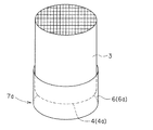
まず、目封止ハニカム構造体の製造方法の一例について説明する。図1は、目封止ハニカム構造体の製造方法の一例によって製造された目封止ハニカム構造体を模式的に示す斜視図である。本目封止ハニカム構造体の製造方法は、図1に示すような、多孔質体からなる隔壁2を有し、隔壁2によって、流体の流路となる多数のセル4が区画・形成された筒状のハニカム構造体3と、ハニカム構造体3のセル4のいずれかの開口部を塞栓する目封止部5とを備えた目封止ハニカム構造体1を製造するための方法である。
First, an example of a method for manufacturing a plugged honeycomb structure will be described. FIG. 1 is a perspective view schematically showing a plugged honeycomb structure manufactured by an example of a method for manufacturing a plugged honeycomb structure. The present plugged honeycomb structure manufacturing method has a
本目封止ハニカム構造体の製造方法は、図2に示すように、ハニカム構造体3の目封止すべきセル4a(目封止セル)が開口している側の一方の端部7aの外周側を覆うように且つその先端部が一方の端部7aの端面から突出するように目封止充填用冶具6を配設し、一方の端部7a側の端面を外周空間から区画し、図3及び図4に示すように、目封止充填用冶具6を配設したハニカム構造体3の一方の端部7aをセラミックスラリー9に押し付けることにより、目封止セル4aの内部にセラミックスラリー9を導入して目封止部5(図1参照)を形成する。なお、図2〜図4は、本目封止ハニカム構造体の製造方法における、目封止セルの内部にセラミックスラリーを導入する工程を説明する説明図であり、ハニカム構造体の軸方向に平行な断面図である。
As shown in FIG. 2, the manufacturing method of the present plugged honeycomb structure includes an outer periphery of one end portion 7a on the side where the
このように構成することによって、一方の端部7a側の外周空間から区画された部位に、目封止セル4aの内部に導入するセラミックスラリー9を所定量区画することができる。このため、ハニカム構造体3の一方の端部7aをセラミックスラリー9に押し付けた際に、目封止セル4aの内部に導入されるべきセラミックスラリー9が、ハニカム構造体3の一方の端部7aから外周方向に流動するのを有効に防止することができ、目封止セルの内部に均等な深さでセラミックスラリー9を導入することができる。
By comprising in this way, the
本目封止ハニカム構造体の製造方法においては、目封止セル4a以外のセルにはセラミックスラリー9が導入されないように、ハニカム構造体3の一方の端部7aの端面に、目封止セル4aと連通し得る孔部が形成された目封止部形成用マスク8を配設する。この目封止部形成用マスク8は、従来の目封止ハニカム構造体の製造方法に用いられる目封止部形成用マスクを好適に用いることができる。なお、上記した目封止充填用冶具6を配設する際には、ハニカム構造体3に目封止部形成用マスク8を配設した後に、この目封止充填用冶具6を配設することが好ましい。このように構成することによって、目封止セル4aへのセラミックスラリー9の導入を良好に行うことができる。
In the manufacturing method of the plugged honeycomb structure, plugged
なお、図2〜図4においては、平板の部材10上にセラミックスラリー9が載置され、このセラミックスラリー9にハニカム構造体3の一方の端部7a側を押し付ける場合を示しているが、使用するセラミックスラリー9は底面と側面とを有する容器等の内部に貯留してもよい。
2 to 4 show the case where the
また、平板の部材10上に載置するセラミックスラリー9の厚さ(容器等の内部にセラミックスラリーを貯留する場合には、セラミックスラリーの深さ)については、目封止セル4aにセラミックスラリー9を導入する深さ(以下、「目封止深さ」ということがある)の1/3程度であることが好ましい。
Further, the thickness of the
また、セラミックスラリー9は、スキージ等の部材によって表面を均すことにより、より均等な深さで目封止セル4aの内部に導入することが可能となる。
Moreover, the
本目封止ハニカム構造体の製造方法に用いられるハニカム構造体3は、図1に示すように、多孔質体からなる隔壁2を有し、隔壁2によって、流体の流路となる多数のセル4が区画・形成された筒状のものである。なお、ハニカム構造体3は、隔壁2が極めて薄い多孔体によって構成された、比較的脆弱な構造体である。従って、その外周を被覆するように、補強部材としての外壁12を更に備えた構造とすることが一般的である。これにより、ハニカム構造体3全体の機械的強度を向上させることができ、使用時における変形や破損等を有効に防止することができる。
As shown in FIG. 1, the
上記の条件を満たす限り、ハニカム構造体3(隔壁2、外壁12)を構成する材質については特に制限はないが、隔壁2が多孔質であることが必要であるため、通常は、セラミック(例えば、コージェライト等)からなるものが好適に用いられる。
As long as the above conditions are satisfied, the material constituting the honeycomb structure 3 (the
本目封止ハニカム構造体の製造方法に用いられるハニカム構造体3は、上記したようなセラミックからなる材料を成形した未乾燥の成形体であってもよいし、成形体を乾燥してなる乾燥体であってもよいし、乾燥体を焼成してなる焼結体であってもよい。
The
また、ハニカム構造体3の形状についても特に限定されず、例えば、円筒状、四角柱状、三角柱状等の各種形状を採用することができる。また、セル形状(流路に対して垂直な面におけるセル4の形状)についても特に限定はされず、例えば、三角形、四角形、六角形、八角形等の各種多角形状や丸、長円、楕円形状を単独又は組合わせ採用することができる。
Further, the shape of the
本目封止ハニカム構造体の製造方法においては、ハニカム構造体3を製造する方法については特に制限はないが、例えば、適当な粘度に調整したセラミック坏土を、所望のセル形状、隔壁厚さ、セル密度(セルピッチ)を有する口金を用いて押出成形し、乾燥することによりハニカム構造体3を得るといった方法等を好適例として挙げることができる。また、目封止部5のパターンは千鳥模様が一般的であるが、特にそれに制限されるものではなく、列状や同心円状などであってもよい。
In the method for manufacturing the plugged honeycomb structure, the method for manufacturing the
本目封止ハニカム構造体の製造方法は、図2に示すように、このように構成されたハニカム構造体3の目封止すべきセル4a(目封止セル)が開口している側の一方の端部7aの外周側を覆うように且つその先端部が一方の端部7aの端面から突出するように目封止充填用冶具6を配設し、一方の端部7a側の端面を外周空間から区画し、ハニカム構造体3の目封止セル4aの内部に目封止部5(図1参照)となるセラミックスラリー9を導入して目封止部5(図1参照)を形成するものである。
As shown in FIG. 2, the manufacturing method of the present plugged honeycomb structure includes one side on the side where the
本目封止ハニカム構造体の製造方法に使用するセラミックスラリー9を構成する材質については特に制限はないが、セラミックの粉末、例えば、コージェライトの粉末に、バインダーや分散媒等を加えて混練したものを好適に用いることができる。セラミックの粉末の種類については、例えば、図1に示すハニカム構造体3の隔壁2を構成する材料と同一種類のものであることが好ましい。
The material constituting the
本目封止ハニカム構造体の製造方法においては、例えば、図5に示すように、目封止充填用冶具6として弾性を有する筒状体6aを用い、この目封止充填用冶具6の弾性力により、ハニカム構造体3の一方の端部7a側に目封止充填用冶具6を配設することができる。このような目封止充填用冶具6は、弾性力によりハニカム構造体3の径方向に密着性を有するため、ハニカム構造体3の一方の端部7a側に簡便且つ確実に配設することができる。
In the method for manufacturing the plugged honeycomb structure, for example, as shown in FIG. 5, a
このような弾性を有する筒状体6aからなる目封止充填用冶具6としては、ジエン系ゴムや非ジエン系ゴム等の従来公知のゴムから形成されたものを用いることができ、例えば、天然ゴム、合成イソプレンゴム、ブタジエンゴム、スチレン−ブタジエンゴム、エチレン−α−オレフィン共重合ゴム、エチレン−α−オレフィン−ジエン共重合ゴム、アクリロニトリル−ブタジエン共重合ゴム、クロロプレンゴム、ハロゲン化ブチルゴム、シリコンゴム、フッ素ゴム、ウレタンゴム、アクリルゴム、塩素化ポリエチレン等からなる筒状体を好適例として挙げることができる。
As the plugging and filling
また、本目封止ハニカム構造体の製造方法に用いられる目封止充填用冶具の他の例として、例えば、図6に示すように、目封止充填用冶具6として帯状体6bを用い、この帯状体6bをハニカム構造体3の一方の端部7a側に捲き付けることにより、ハニカム構造体3の一方の端部7a側に目封止充填用冶具6を配設することもできる。このような目封止充填用冶具6は、ハニカム構造体3の一方の端部7a側に捲き付けて使用するため、異なる形状や大きさのハニカム構造体3に対応させることができる。特に、帯状体6bをハニカム構造体3の一方の端部7a側に捲き付ける際には、この帯状体6bが二重以上に重なるようにして捲き付けてもよいため、帯状体6bの長さを比較的に長くしておくことで、より様々な形状や大きさのハニカム構造体3に対応させることが可能となる。
Further, as another example of the plugging and filling jig used in the manufacturing method of the plugged honeycomb structure, for example, as shown in FIG. 6, a band-
このような帯状体6bからなる目封止充填用冶具6としては、例えば、樹脂、金属、合金等の材料からなるものを好適例として挙げることができる。樹脂性の帯状体6bとしては、例えば、厚さが0.1〜0.5mm程度のポリエチレンフィルムや、ポリプロピレン樹脂を表面にコートしたクラフト紙等を用いることができる。この樹脂性の帯状体6bは、ハニカム構造体3の一方の端部7a側に捲き付けた後、接着、融着、又は粘着テープ等を用いて固定する。
As the plugging and filling
また、薄い金属や合金からなる帯状体6bの場合にも、ハニカム構造体3の一方の端部7a側に捲き付けた後、接着、融着、又は粘着テープ等を用いて固定することができる。また、帯状体6bが板バネによって形成されている場合には、ハニカム構造体3に捲き付ける方向に復元力を生じさせて、その復元力によってハニカム構造体3の一方の端部7aに固定することが可能となる。このような帯状体6bとしては、例えば、厚さ0.1〜0.3mmのステンレス板を用いることができる。
Further, in the case of the band-
また、本目封止ハニカム構造体の製造方法においては、図7に示すように、目封止充填用冶具6として、一方の端部7a側の端面を外周空間から区画するための筒状体6a(図7においては、筒状体6aの場合を示している)又は帯状体6b(図6参照)と、この筒状体6a又は帯状体6b(図6参照)をハニカム構造体3の一方の端部7aに保持するための保持部6cとを有するものを用いてもよい。このように目封止充填用冶具6として保持部6cを有するものを用いることにより、筒状体6a又は帯状体6b(図6参照)自体がハニカム構造体3に対して密着性を有する必要がなくなり、例えば、上記した樹脂性のフィルム等を接着して固定する必要がなくなる。ここで、図7は、目封止ハニカム構造体の製造方法における、目封止セルの内部にセラミックスラリーを導入する工程の他の例を説明する説明図であり、ハニカム構造体の軸方向に平行な断面図である。
Moreover, in the manufacturing method of this plugged honeycomb structure, as shown in FIG. 7, as a plugging
保持部6cとしては、筒状体6a又は帯状体6b(図6参照)をハニカム構造体3の一方の端部7aに保持することが可能なものであれば特に制限はないが、例えば、コイルバネや、加減圧することによりハニカム構造体3の外周部分を締め付けることが可能なチューブ体を好適例として挙げることができる。
The holding portion 6c is not particularly limited as long as it can hold the
また、本目封止ハニカム構造体の製造方法においては、目封止充填用冶具6として、セラミックスラリー9に押し付けた際にハニカム構造体3の径方向に対する変形が生じない剛性を有するもの、即ち、押し付け時に生じるセラミックスラリー9の内圧に耐え得るものを用いることが好ましい。このような目封止充填用冶具6を用いることにより、一方の端部7a側の端面を外周空間から区画する領域の大きさを一定に保つことができ、目封止セル4aの内部に導入するセラミックスラリー9の量を正確に制御することができる。
Further, in the present plugged honeycomb structure manufacturing method, the plugging and filling
なお、このハニカム構造体3の径方向に対する変形が生じない剛性は、使用するセラミックスラリー9の組成やその粘度、また、ハニカム構造体3の外形の大きさ等によって決まる値であることから、それぞれの条件に応じて適宜決定することが好ましい。
The rigidity of the
また、本目封止ハニカム構造体の製造方法においては、図2〜図4に示すように、目封止充填用冶具6の先端部をハニカム構造体3の一方の端部7a側の端面までスライドさせながら、ハニカム構造体3の一方の端部7aをセラミックスラリー9に押し付けることが好ましい。これにより、最終的にハニカム構造体3の一方の端部7a側の端面を、セラミックスラリー9を載置した平板の部材10上(例えば、セラミックスラリー9を容器等に貯留している場合には、その容器の底面)に押し付けることができ、目封止充填用冶具6によって区画した領域に存在するセラミックスラリー9を目封止セル4aの内部に全量導入することができる。
Further, in the manufacturing method of the plugged honeycomb structure, as shown in FIGS. 2 to 4, the front end portion of the plugging filling
なお、本目封止ハニカム構造体の製造方法においては、このようにしてハニカム構造体3の一方の端部7aにおける目封止セル4aの内部にセラミックスラリー9を導入した後、このハニカム構造体3の他方の端部7bにおいても、一方の端部7aにおける目封止セル4a以外のセル4bに対して、上記方法と同様の方法によってセラミックスラリー9を導入してもよい。これにより、ハニカム構造体3の一方の端部7aと他方の端部7bとのセル4に互い違いに目封止部5(図1参照)を形成することができる。
In the method for manufacturing the plugged honeycomb structure, after the
このようにして所定のセル4にセラミックスラリー9を導入した後、このセラミックスラリー9を乾燥し、更に焼成することによって、図1に示すような、多孔質体からなる隔壁2を有し、隔壁2によって、流体の流路となる多数のセル4が区画・形成された筒状のハニカム構造体3と、ハニカム構造体3のセル4のいずれかの開口部を塞栓する目封止部5とを備えた目封止ハニカム構造体1を製造する。なお、目封止する際に使用したハニカム構造体3が、未焼成の成形体又は乾燥のみを行った乾燥体である場合には、目封止セル4aの内部に導入したセラミックスラリー9(図4参照)と同時に、ハニカム構造体3の乾燥及び焼成を行って目封止ハニカム構造体1を製造する。
After the
次に、本発明の目封止ハニカム構造体の製造方法の一の実施の形態について説明する。本実施の形態の目封止ハニカム構造体の製造方法も、これまでに説明した目封止ハニカム構造体の製造方法と同様に、図1に示すような、多孔質体からなる隔壁2を有し、隔壁2によって、流体の流路となる多数のセル4が区画・形成された筒状のハニカム構造体3と、ハニカム構造体3のセル4のいずれかの開口部を塞栓する目封止部5とを備えた目封止ハニカム構造体1を製造するための方法である。
Next, an embodiment of a method for manufacturing a plugged honeycomb structure of the present invention will be described. The method for manufacturing a plugged honeycomb structure of the present embodiment also has
本実施の形態の目封止ハニカム構造体の製造方法は、図8に示すように、ハニカム構造体3の目封止すべきセル(目封止セル4a)が開口している側の一方の端部7aの外周側を覆うように且つその先端部が一方の端部7aの端面と略同位置となるように目封止充填用冶具16を配設して、ハニカム構造体3の一方の端部7a側の外径を増大させ、図9及び図10に示すように、目封止充填用冶具16を配設したハニカム構造体3の一方の端部7aを、セラミックスラリー9に押し付けることにより、目封止セル4aの内部にセラミックスラリー9を導入して目封止部5(図1参照)を形成する目封止ハニカム構造体の製造方法である。なお、図8〜図10は、本実施の形態の目封止ハニカム構造体の製造方法における、目封止セルの内部にセラミックスラリーを導入する工程を説明する説明図であり、ハニカム構造体の軸方向に平行な断面図である。
As shown in FIG. 8, the manufacturing method of the plugged honeycomb structure of the present embodiment is one side of the
目封止ハニカム構造体の製造方法の一例において説明したように、従来の目封止ハニカム構造体の製造方法においては、図19に示すように、ハニカム構造体21の一方の端部をスラリー29(セラミックスラリー)に押し付けた際に、目封止セル24aの内部に導入されるべきスラリー29が、ハニカム構造体21の一方の端部から外周方向に流動してしまい、目封止セル24aに均等な深さでスラリー29が導入されないという問題があった。
As described in the example of the method for manufacturing the plugged honeycomb structure, in the conventional method for manufacturing the plugged honeycomb structure, as shown in FIG. When pressed against (ceramic slurry), the
このような問題は、スラリー29が流動性を有するため、押し付け時により抵抗の少ない方へ流動してしまうことが原因であることから、スラリー29の流動による目封止深さへの影響は、ハニカム構造体21のより外周側においてより顕著なものであり、逆に、ハニカム構造体21の外壁から所定距離離れた内側においては、スラリー29の流動の影響が少なく、略同一の深さでスラリー29が導入されているということが確認された。
Such a problem is caused by the fact that the
このため、本実施の形態の目封止ハニカム構造体の製造方法は、従来の方法ではセラミックスラリーの導入量が著しく低下し問題となっていた外周側の部位に対して、図8に示すような目封止充填用冶具16を配設して、目封止充填用冶具16を配設した部位の外周の大きさを増大させることにより、実際にセラミックスラリー9の導入を行うハニカム構造体3に対しては、セラミックスラリー9の流動による目封止深さへの影響を極めて小さくする。これにより、ハニカム構造体3の目封止セル4aの内部に均等な深さでセラミックスラリー9を導入することができる。
For this reason, the manufacturing method of the plugged honeycomb structure of the present embodiment is as shown in FIG. 8 with respect to the outer peripheral portion where the amount of ceramic slurry introduced has been significantly reduced in the conventional method. The
本実施の形態の目封止ハニカム構造体の製造方法においては、目封止セル4a以外のセルにはセラミックスラリー9が導入されないように、ハニカム構造体3の一方の端部7aの端面には、目封止セル4aと連通し得る孔部が形成された目封止部形成用マスク8を配設する。この目封止部形成用マスク8は、従来の目封止ハニカム構造体の製造方法に用いられる目封止部形成用マスクを好適に用いることができる。なお、上記した目封止充填用冶具16を配設する際には、ハニカム構造体3に目封止部形成用マスク8を配設した後に、目封止充填用冶具16を配設することが好ましい。このように構成することによって、目封止セル4aへのセラミックスラリー9の導入を良好に行うことができる。
In the manufacturing method of the plugged honeycomb structure of the present embodiment, the end surface of one end portion 7a of the
なお、本実施の形態の目封止ハニカム構造体の製造方法においては、使用するハニカム構造体3及びセラミックスラリー9については、目封止ハニカム構造体の製造方法の一例において説明したものと同様のものを好適に用いることができる。また、セラミックスラリー9は、目封止ハニカム構造体の製造方法の一例にて説明したものと同様に、平板の部材10上に載置したり、容器(図示せず)等の内部に貯留したりしたものを用いることができる。
In the manufacturing method of the plugged honeycomb structure of the present embodiment, the
本実施の形態の目封止ハニカム構造体の製造方法においては、目封止充填用冶具16を配設することによりハニカム構造体3の一方の端部7a側の外径を増大させ、従来の方法ではセラミックスラリー9の導入量が著しく低下する外周部分を目封止充填用冶具16で占拠してしまうことが必要である。
In the manufacturing method of the plugged honeycomb structure of the present embodiment, the outer diameter on the one end portion 7a side of the
なお、セラミックスラリー9を導入した場合、その導入量が著しく低下する範囲の大きさは、セラミックスラリー9を導入する目封止深さや、使用するセラミックスラリー9の粘度等によって決まるため、これらに応じて適宜決定することが好ましい。例えば、ハニカム構造体3の一方の端部7a側の外径を、目封止深さの3分の2以上の長さを増大させることが好ましい。なお、特に限定されることはないが、この際に使用するセラミックスラリー9の粘性は、例えば、150〜500dPa・s程度であることが好ましい。
In addition, when the
本実施の形態の目封止ハニカム構造体の製造方法に用いられる目封止充填用冶具16としては、図11に示すように、目封止セル4が形成されたハニカム構造体3の外周の大きさに対応した内径を有し、ハニカム構造体3の一方の端部7a側の外周の大きさを増大させ得る厚さの筒状体16aからなり、ハニカム構造体3の一方の端部7a側に設置・固定が可能なものを挙げることができる。特に、このような筒状体16aからなる目封止充填用冶具16としては、弾性を有するものを用いる。このような目封止充填用冶具16は、弾性力によりハニカム構造体3の径方向に密着性を有するため、ハニカム構造体3の一方の端部7a側に簡便且つ確実に配設することができる。
As the plugging filling
このような弾性を有する筒状体からなる目封止充填用冶具としては、ジエン系ゴムや非ジエン系ゴム等の従来公知のゴムから形成されたものを用いることができ、例えば、天然ゴム、合成イソプレンゴム、ブタジエンゴム、スチレン−ブタジエンゴム、エチレン−α−オレフィン共重合ゴム、エチレン−α−オレフィン−ジエン共重合ゴム、アクリロニトリル−ブタジエン共重合ゴム、クロロプレンゴム、ハロゲン化ブチルゴム、シリコンゴム、フッ素ゴム、ウレタンゴム、アクリルゴム、塩素化ポリエチレン等からなる筒状体を好適例として挙げることができる。 As the plugging and filling jig made of such a cylindrical body having elasticity, one formed from a conventionally known rubber such as a diene rubber or a non-diene rubber can be used. For example, natural rubber, Synthetic isoprene rubber, butadiene rubber, styrene-butadiene rubber, ethylene-α-olefin copolymer rubber, ethylene-α-olefin-diene copolymer rubber, acrylonitrile-butadiene copolymer rubber, chloroprene rubber, halogenated butyl rubber, silicon rubber, fluorine Preferable examples include cylindrical bodies made of rubber, urethane rubber, acrylic rubber, chlorinated polyethylene, and the like.
また、図示は省略するが、本実施の形態の目封止ハニカム構造体の製造方法においては、目封止充填用冶具として、比較的に長さの長い帯状体を用い、この帯状体をハニカム構造体の一方の端部側に複数回捲き付けるようして設置・固定が可能なものを用いることもできる。 Although not shown, in the method for manufacturing a plugged honeycomb structure of the present embodiment, a relatively long strip is used as a plugging filling jig, and the strip is used as a honeycomb. It is also possible to use a structure that can be installed and fixed by being rubbed multiple times on one end side of the structure.
また、本実施の形態の目封止ハニカム構造体の製造方法においては、図12に示すように、目封止充填用冶具16として、ハニカム構造体3の端面にて径方向に折れ曲がり、ハニカム構造体3の一方の端部側の外径を増大させるように構成された筒状体16aと、この筒状体16aをハニカム構造体3の一方の端部7aに保持するための保持部16cとを有するものを用いることもできる。このように目封止充填用冶具16として保持部16cを有するものを用いることにより、筒状体16a自体がハニカム構造体3に対して密着性を有するものである必要がなくなる。
Further, in the manufacturing method of the plugged honeycomb structure of the present embodiment, as shown in FIG. 12, the plugging and filling
また、目封止充填用冶具16としては、ハニカム構造体3の端面における外径を増大させることができれば、セラミックスラリー9の流動による目封止深さへの影響を減少させる効果を得ることができるため、ハニカム構造体3の端面にて径方向に折れ曲がり、ハニカム構造体3の一方の端部側の外径を増大させるように構成された筒状体16aを用いてもよい。
Moreover, as the plugging and filling
なお、保持部16cとしては、筒状体16aをハニカム構造体3の一方の端部7aに保持することが可能なものであれば特に制限はないが、例えば、コイルバネや、加減圧することによりハニカム構造体3の外周部分を締め付けることが可能なチューブ体を好適例として挙げることができる。
The holding portion 16c is not particularly limited as long as it can hold the
なお、本実施の形態の目封止ハニカム構造体の製造方法においては、図8〜図10に示すように、ハニカム構造体3の一方の端部7aをセラミックスラリー9に押し付けている間は、目封止充填用冶具16がハニカム構造体3の軸方向に移動しないように固定しておくことが好ましい。目封止充填用冶具16がハニカム構造体3の軸方向に移動してしまうと、押し付け時におけるセラミックスラリー9の流動状態に変化が生じてしまい、目封止セル4aに均一にセラミックスラリー9が充填され難くなることがある。
In the method for manufacturing a plugged honeycomb structure of the present embodiment, as shown in FIGS. 8 to 10, while one end portion 7 a of the
このようにして、ハニカム構造体3の目封止セル4aの内部にセラミックスラリー9を導入した後、このセラミックスラリー9を乾燥し、更に焼成することによって、図1に示すような、多孔質体からなる隔壁2を有し、隔壁2によって、流体の流路となる多数のセル4が区画・形成された筒状のハニカム構造体3と、ハニカム構造体3のセル4のいずれかの開口部を塞栓する目封止部5とを備えた目封止ハニカム構造体1を製造する。なお、目封止する際に使用したハニカム構造体3が、未焼成の成形体又は乾燥のみを行った乾燥体である場合には、目封止セル4aの内部に導入したセラミックスラリー9(図10参照)と同時に、ハニカム構造体3の乾燥及び焼成を行って目封止ハニカム構造体1を製造する。
In this way, after the
なお、本実施の形態の目封止ハニカム構造体の製造方法においても、ハニカム構造体3の一方の端部7aにおける目封止を行った後、このハニカム構造体3の他方の端部7bにおいても、一方の端部7aにおける目封止セル4a以外のセル4bに対して、上記方法と同様の方法によってセラミックスラリー9を導入してもよい。
In the method for manufacturing a plugged honeycomb structure of the present embodiment, after plugging at one end 7a of the
次に、目封止充填用冶具の一例について説明する。本目封止充填用冶具は、これまでに説明した目封止ハニカム構造体の製造方法に好適に用いられる目封止充填用冶具である。 Next, an example of a plugging and filling jig will be described. This plugging and filling jig is a plugging and filling jig that is preferably used in the method for manufacturing a plugged honeycomb structure described so far.
本目封止充填用冶具は、図5に示すような、ハニカム構造体3の目封止すべきセル4a(目封止セル)が開口している側の一方の端部7aに配設して、ハニカム構造体3の一方の端部7a側の端面を外周空間から区画し、ハニカム構造体3の一方の端部7aをセラミックスラリー9(図2参照)に押し付けることにより、目封止セル4aの内部にセラミックスラリー9(図2参照)を導入するために用いられる目封止充填用冶具6であって、目封止セル4aが形成されたハニカム構造体3の外周の大きさに対応した内径を有する筒状体6aからなり、ハニカム構造体3の一方の端部7a側の端面を外周空間から区画するように設置・固定が可能な目封止充填用冶具6である。
The plugging filling jig is disposed at one end 7a on the side where the
本目封止充填用冶具6は、一方の端部7a側の外周空間から区画された部位に、目封止セル4aの内部に導入するセラミックスラリー9(図2参照)を所定量区画することができ、ハニカム構造体3の一方の端部7aをセラミックスラリー9(図2参照)に押し付けた際に、目封止セル4aの内部に均等な深さでセラミックスラリー9(図2参照)を導入することができる。
The plugging
また、本目封止充填用冶具6は、弾性を有する筒状体6aからなることが好ましい。このような目封止充填用冶具6は、その弾性力によりハニカム構造体3の径方向に密着性を有するため、ハニカム構造体3の一方の端部7a側に簡便且つ確実に配設することができる。
Further, the plugging and filling
このような弾性を有する筒状体6aからなる目封止充填用冶具6としては、ジエン系ゴムや非ジエン系ゴム等の従来公知のゴムから形成されたものを用いることができ、例えば、天然ゴム、合成イソプレンゴム、ブタジエンゴム、スチレン−ブタジエンゴム、エチレン−α−オレフィン共重合ゴム、エチレン−α−オレフィン−ジエン共重合ゴム、アクリロニトリル−ブタジエン共重合ゴム、クロロプレンゴム、ハロゲン化ブチルゴム、シリコンゴム、フッ素ゴム、ウレタンゴム、アクリルゴム、塩素化ポリエチレン等からなる筒状体を好適例として挙げることができる。
As the plugging and filling
なお、本目封止充填用冶具6は、目封止ハニカム構造体の製造方法の一例において説明した筒状体からなる目封止充填用冶具と同様に構成されたものであり、目封止ハニカム構造体の製造方法の一例にて説明した方法によって使用することができる。
The plugging and filling
次に、目封止充填用冶具の他の例について説明する。本目封止充填用冶具は、これまでに説明した目封止ハニカム構造体の製造方法に好適に用いられる目封止充填用冶具である。 Next, another example of the plugging and filling jig will be described. This plugging and filling jig is a plugging and filling jig that is preferably used in the method for manufacturing a plugged honeycomb structure described so far.
本目封止充填用冶具は、図6に示すように、ハニカム構造体3の目封止すべきセル4a(目封止セル)が開口している側の一方の端部7aに配設して、ハニカム構造体3の一方の端部7a側の端面を外周空間から区画し、ハニカム構造体3の一方の端部7aをセラミックスラリー9(図2参照)に押し付けることにより、目封止セル4aの内部にセラミックスラリー9(図2参照)を導入するために用いられる目封止充填用冶具6であって、ハニカム構造体3の外周の長さよりも長い帯状体6bからなり、ハニカム構造体3の外周に捲き付けることにより、ハニカム構造体3の一方の端部7a側の端面を外周空間から区画するように設置・固定が可能な目封止充填用冶具6である。
As shown in FIG. 6, the plugging filling jig is disposed at one end portion 7a on the side where the
本目封止充填用冶具6は、一方の端部7a側の外周空間から区画された部位に、目封止セル4aの内部に導入するセラミックスラリー9(図2参照)を所定量区画することができ、ハニカム構造体3の一方の端部7aをセラミックスラリー9(図2参照)に押し付けた際に、目封止セル4aの内部に均等な深さでセラミックスラリー9(図2参照)を導入することができる。
The plugging
このような帯状体6bからなる目封止充填用冶具6としては、例えば、樹脂、金属、合金等の材料からなるものを好適例として挙げることができる。樹脂性の帯状体6aとしては、例えば、厚さが0.1〜0.5mm程度のポリエチレンフィルムや、ポリプロピレン樹脂を表面にコートしたクラフト紙等を用いることができる。この樹脂性の帯状体6aは、ハニカム構造体3の一方の端部7a側に捲き付けた後、接着、融着、又は粘着テープ等を用いて固定する。
As the plugging and filling
また、薄い金属や合金からなる帯状体6bの場合にも、ハニカム構造体3の一方の端部7a側に捲き付けた後、接着、融着、又は粘着テープ等を用いて固定することができる。また、帯状体6bが板バネによって形成されている場合には、ハニカム構造体3の一方の端部7aに捲き付ける方向に復元力を生じさせて、その復元力によってハニカム構造体3の一方の端部7aに固定することが可能となる。このような帯状体6bとしては、例えば、厚さ0.1〜0.3mmのステンレス板を用いることができる。なお、本実施の形態の目封止充填用冶具6は、第一の発明の実施の形態に説明した帯状体からなる目封止充填用冶具と同様に構成されたものであり、第一の発明の実施の形態にて説明した方法によって使用することができる。
Further, in the case of the band-
次に、本発明の目封止充填用冶具の一の実施の形態について説明する。本実施の形態の目封止充填用冶具は、本発明の目封止ハニカム構造体の製造方法の実施の形態に好適に用いられる目封止充填用冶具である。 Next, an embodiment of the plugging and filling jig of the present invention will be described. The plugging and filling jig of the present embodiment is a plugging and filling jig suitably used in the embodiment of the method for manufacturing a plugged honeycomb structure of the present invention.
本実施の形態の目封止充填用冶具は、図11に示すように、ハニカム構造体3の目封止すべきセル4a(目封止セル)が開口している側の一方の端部7aに配設して、ハニカム構造体3の一方の端部7a側の外径を増大させ、そのハニカム構造体3の一方の端部7aをセラミックスラリー9(図8参照)に押し付けることにより、目封止セル4aの内部にセラミックスラリー9(図8参照)を導入するために用いられる目封止充填用冶具16であって、目封止セル4aが形成されたハニカム構造体3の外周の大きさに対応した内径を有し、ハニカム構造体3の一方の端部7a側の外径を増大させ得る厚さの筒状体16aからなり、ハニカム構造体3の一方の端部7a側に設置・固定が可能な目封止充填用冶具16である。
As shown in FIG. 11, the plugging and filling jig of the present embodiment has one end 7a on the side where the
本実施の形態の目封止充填用冶具16をハニカム構造体3の一方の端部7a側に配設することにより、この目封止充填用冶具16によって一方の端部7a側の外径を増大させ、従来の方法ではセラミックスラリーの導入量が著しく低下し問題となっていた外周側の部位を目封止充填用冶具で占拠させることができる。このため、目封止充填用冶具16の外側面からその厚さ分だけ内側に位置するハニカム構造体3に対しては、セラミックスラリー9(図8参照)の流動による目封止深さへの影響を極めて小さくすることができ、ハニカム構造体3の一方の端部7aをセラミックスラリー9(図8参照)に押し付けた際に、目封止セル4aの内部に均等な深さでセラミックスラリー9(図8参照)を導入することができる。
By disposing the plugging and filling
なお、本実施の形態の目封止充填用冶具16は、本発明の目封止ハニカム構造体の製造方法の実施の形態にて説明した目封止充填用冶具と同様に構成されたものであり、本発明の目封止ハニカム構造体の製造方法の実施の形態にて説明した方法によって使用することができる。また、本実施の形態の目封止充填用冶具16は、図12に示すように、目封止充填用冶具16として、ハニカム構造体3の端面にて径方向に折れ曲がり、ハニカム構造体3の一方の端部側の外径を増大させるように構成された筒状体16aと、この筒状体16aをハニカム構造体3の一方の端部7aに保持するための保持部16cとを有するものであってもよい。
The plugging and filling
以下、本発明を実施例により具体的に説明するが、本発明は以下の実施例に限定されるものではない。 EXAMPLES Hereinafter, although an Example demonstrates this invention concretely, this invention is not limited to a following example.
(参考例1)
本参考例においては、使用するハニカム構造体として、多孔質体からなる隔壁を有し、隔壁によって流体の流路となる多数のセルが区画・形成された筒状のハニカム構造体を用意した。このハニカム構造体は、コージェライトから構成され、端面の形状が250mmφの円形の円筒状であり、セル形状は四角形、隔壁厚さは0.3mm(12mil)、セル密度は46.5セル/cm2(300セル/平方インチ)のものであった。このハニカム構造体の端面の対角線上には、85個のセルが存在している。なお、1milは、1000分の1インチであり、約0.025mmである。
(Reference Example 1)
In this reference example, a tubular honeycomb structure having a partition wall made of a porous body and having a plurality of cells partitioned and formed as fluid flow paths by the partition wall was prepared as the honeycomb structure to be used. This honeycomb structure is made of cordierite and has a circular cylindrical shape with an end face shape of 250 mmφ, a cell shape is square, a partition wall thickness is 0.3 mm (12 mil), and a cell density is 46.5 cells / cm. 2 (300 cells / square inch). There are 85 cells on the diagonal of the end face of the honeycomb structure. In addition, 1 mil is 1/1000 inch and is about 0.025 mm.
上記のハニカム構造体は、適当な粘度に調整した坏土を上記セル形状、隔壁厚さ、セル密度を有する口金を用いて押出成形し、乾燥後、両端面を切断して平滑面とすることにより製造した。 The above honeycomb structure is formed by extruding a clay adjusted to an appropriate viscosity using a die having the above cell shape, partition wall thickness, and cell density, and after drying, both end surfaces are cut into smooth surfaces. Manufactured by.
このようなハニカム構造体に、厚さ8mmのアメゴム製の筒状体からなる目封止充填用冶具を、目封止セルが開口している側の一方の端部の外周側を覆うように且つその先端部が一方の端部の端面から突出するように配設し、一方の端部側の端面を外周空間から区画し、この目封止充填用冶具を配設したハニカム構造体の一方の端部をセラミックスラリーに押し付けることにより、目封止セルの内部にセラミックスラリーを導入した。本参考例においては、各目封止セルに導入するセラミックスラリーの狙いの深さを5mmとした。 In such a honeycomb structure, a plugging and filling jig made of a cylindrical body made of candy rubber having a thickness of 8 mm is provided so as to cover the outer peripheral side of one end portion on the side where the plugging cells are open. One end of the honeycomb structure in which the tip end portion is arranged so as to protrude from the end face of one end portion, the end face on one end side is partitioned from the outer peripheral space, and the plugging and filling jig is provided. The ceramic slurry was introduced into the plugged cell by pressing the end of the ceramic slurry onto the ceramic slurry. In this reference example, the target depth of the ceramic slurry introduced into each plugged cell was 5 mm.
このようにして目封止セルにセラミックスラリーを導入した後、各目封止セルに導入されたセラミックスラリーの深さ(以下、「目封止深さ」という)を、端面の対角線上の85セルについて測定した。ここで、図13は、端面の対角線上の85セルにおける各目封止深さを示すグラフである。なお、図13において、縦軸が、目封止深さ(mm)を示し、横軸が、端面の対角線上の85セルの位置を示す。また、各外周側の10セル(即ち、図13における、セル位置1〜10及びセル位置76〜85)における目封止深さ(mm)を表1に示す。
After the ceramic slurry is introduced into the plugged cells in this way, the depth of the ceramic slurry introduced to each plugged cell (hereinafter referred to as “plugged depth”) is set to 85 on the diagonal of the end face. The cell was measured. Here, FIG. 13 is a graph showing each plugging depth in 85 cells on the diagonal of the end face. In FIG. 13, the vertical axis represents the plugging depth (mm), and the horizontal axis represents the position of 85 cells on the diagonal of the end face. Table 1 shows plugging depths (mm) in 10 cells on each outer peripheral side (that is,

(比較例1)
参考例1と同様のハニカム構造体に目封止充填用冶具を配設することなく、そのままの状態でセラミックスラリーに押し付けることにより、目封止セルの内部にセラミックスラリーを導入した。このようにして目封止セルにセラミックスラリーを導入した後、各目封止深さを、端面の対角線上の85セルについて測定した。ここで、図14は、端面の対角線上の85セルにおける各目封止深さを示すグラフである。なお、図14において、縦軸が、目封止深さ(mm)を示し、横軸が、端面の対角線上の85セルの位置を示す。また、各外周側の10セル(即ち、図14における、セル位置1〜10及びセル位置76〜85)における目封止深さ(mm)を表1に示す。
(Comparative Example 1)
The ceramic slurry was introduced into the plugged cells by pressing against the ceramic slurry as it was without disposing the plugging filling jig in the same honeycomb structure as in Reference Example 1. After introducing the ceramic slurry into the plugged cells in this way, each plugged depth was measured for 85 cells on the diagonal of the end face. Here, FIG. 14 is a graph showing each plugging depth in 85 cells on the diagonal of the end face. In FIG. 14, the vertical axis represents the plugging depth (mm), and the horizontal axis represents the position of 85 cells on the diagonal of the end face. Table 1 shows plugging depths (mm) in 10 cells on each outer peripheral side (that is,
図13、図14及び表1に示すように、比較例1によって得られた目封止ハニカム構造体は、各外周側の10セルの目封止深さが低下していたが、参考例1によって得られた目封止ハニカム構造体は、各外周側の10セルの目封止深さの低下が確認されなかった。なお、参考例1において、外周側の目封止深さが若干深くなった理由は、目封止充填用冶具の厚さによって押し退けられたセラミックスラリーが外周側の目封止セルに導入されたためと考えられる。 As shown in FIGS. 13 and 14 and Table 1, the plugged honeycomb structure obtained in Comparative Example 1 had a reduced plugging depth of 10 cells on each outer peripheral side. In the plugged honeycomb structure obtained by the above, no decrease in the plugging depth of 10 cells on the outer peripheral side was confirmed. In Reference Example 1, the reason that the plugging depth on the outer peripheral side was slightly deeper was that the ceramic slurry pushed away by the thickness of the plugging filling jig was introduced into the plugging cell on the outer peripheral side. it is conceivable that.
(実施例1)
本実施例においては、使用するハニカム構造体として、多孔質体からなる隔壁を有し、隔壁によって流体の流路となる多数のセルが区画・形成された筒状のハニカム構造体を用意した。このハニカム構造体は、コージェライトから構成され、端面の形状が210mmφの円形の円筒状であり、セル形状は四角形、隔壁厚さは0.3mm(12mil)、セル密度は46.5セル/cm2(300セル/平方インチ)のものであった。なお、ハニカム構造体の端面の対角線上には、70個のセルが存在している。
Example 1
In this example, a tubular honeycomb structure having a partition wall made of a porous body and having a plurality of cells partitioned and formed as fluid flow paths by the partition wall was prepared as the honeycomb structure to be used. This honeycomb structure is made of cordierite and has a circular cylindrical shape with an end surface of 210 mmφ, a cell shape of a square, a partition wall thickness of 0.3 mm (12 mil), and a cell density of 46.5 cells / cm. 2 (300 cells / square inch). There are 70 cells on the diagonal of the end face of the honeycomb structure.
上記のハニカム構造体は、適当な粘度に調整した坏土を上記セル形状、隔壁厚さ、セル密度を有する口金を用いて押出成形し、乾燥後、両端面を切断して平滑面とすることにより製造した。 The above honeycomb structure is formed by extruding a clay adjusted to an appropriate viscosity using a die having the above cell shape, partition wall thickness, and cell density, and after drying, both end surfaces are cut into smooth surfaces. Manufactured by.
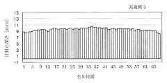
このようなハニカム構造体に、厚さ4mmのアメゴム製の筒状体からなる目封止充填用冶具を、目封止セルが開口している側の一方の端部の外周側を覆うように且つその先端部が一方の端部の端面と略同位置となるように目封止充填用冶具を配設して、ハニカム構造体の一方の端部側の外径を増大させ、この目封止充填用冶具を配設したハニカム構造体の一方の端部をセラミックスラリーに押し付けることにより、目封止セルの内部にセラミックスラリーを導入した。本実施例においては、各目封止セルに導入するセラミックスラリーの狙いの深さを10mmとした。 In such a honeycomb structure, a plugging filling jig made of a cylindrical body made of candy rubber having a thickness of 4 mm is provided so as to cover the outer peripheral side of one end portion on the side where the plugging cells are open. In addition, a plugging and filling jig is disposed so that the tip end portion is substantially in the same position as the end face of one end portion, and the outer diameter on one end portion side of the honeycomb structure is increased. The ceramic slurry was introduced into the plugged cell by pressing one end of the honeycomb structure provided with the stop-filling jig against the ceramic slurry. In this example, the target depth of the ceramic slurry introduced into each plugged cell was 10 mm.
このようにして目封止セルにセラミックスラリーを導入した後、各目封止深さを、端面の対角線上の70セルについて測定した。ここで、図15は、端面の対角線上の70セルにおける各目封止深さを示すグラフである。なお、図15において、縦軸が、目封止深さ(mm)を示し、横軸が、端面の対角線上の70セルの位置を示す。また、各外周側の10セル(即ち、図15における、セル位置1〜10及びセル位置61〜70)における目封止深さ(mm)を表2に示す。
After introducing the ceramic slurry into the plugged cells in this way, each plugged depth was measured for 70 cells on the diagonal of the end face. Here, FIG. 15 is a graph showing each plugging depth in 70 cells on the diagonal of the end face. In FIG. 15, the vertical axis indicates the plugging depth (mm), and the horizontal axis indicates the position of 70 cells on the diagonal of the end face. Table 2 shows plugging depths (mm) in 10 cells on each outer peripheral side (that is,
(実施例2)
実施例1と同様のハニカム構造体に、厚さ8mmのアメゴム製の筒状体からなる目封止充填用冶具を配設し、実施例1と同様方法によって、目封止セルの内部にセラミックスラリーを導入した。このようにして目封止セルにセラミックスラリーを導入した後、各目封止深さを、端面の対角線上の70セルについて測定した。ここで、図16は、端面の対角線上の70セルにおける各目封止深さを示すグラフである。なお、図16において、縦軸が、目封止深さ(mm)を示し、横軸が、端面の対角線上の70セルの位置を示す。また、各外周側の10セル(即ち、図16における、セル位置1〜10及びセル位置61〜70)における目封止深さ(mm)を表2に示す。
(Example 2)
A plugging and filling jig made of an American rubber cylindrical body having a thickness of 8 mm is disposed on the honeycomb structure similar to that in Example 1, and ceramics is formed inside the plugging cell in the same manner as in Example 1. Introduced rally. After introducing the ceramic slurry into the plugged cells in this way, each plugged depth was measured for 70 cells on the diagonal of the end face. Here, FIG. 16 is a graph showing each plugging depth in 70 cells on the diagonal of the end face. In FIG. 16, the vertical axis represents the plugging depth (mm), and the horizontal axis represents the position of 70 cells on the diagonal of the end face. Table 2 shows plugging depths (mm) in 10 cells on each outer peripheral side (that is,
(比較例2)
実施例1と同様のハニカム構造体に目封止充填用冶具を配設することなく、そのままの状態でセラミックスラリーに押し付けることにより、目封止セルの内部にセラミックスラリーを導入した。このようにして目封止セルにセラミックスラリーを導入した後、各目封止深さを、端面の対角線上の70セルについて測定した。ここで、図17は、端面の対角線上の70セルにおける各目封止深さを示すグラフである。なお、図17において、縦軸が、目封止深さ(mm)を示し、横軸が、端面の対角線上の70セルの位置を示す。また、各外周側の10セル(即ち、図17における、セル位置1〜10及びセル位置61〜70)における目封止深さ(mm)を表2に示す。
(Comparative Example 2)
The ceramic slurry was introduced into the plugged cells by pressing against the ceramic slurry as it was without disposing the plugging filling jig in the same honeycomb structure as in Example 1. After introducing the ceramic slurry into the plugged cells in this way, each plugged depth was measured for 70 cells on the diagonal of the end face. Here, FIG. 17 is a graph showing each plugging depth in 70 cells on the diagonal of the end face. In FIG. 17, the vertical axis represents the plugging depth (mm), and the horizontal axis represents the position of 70 cells on the diagonal of the end face. Table 2 shows plugging depths (mm) in 10 cells on each outer peripheral side (that is,
図15、図16、図17及び表2に示すように、比較例2によって得られた目封止ハニカム構造体は、各外周側の10セルの目封止深さが低下していたが、実施例1によって得られた目封止ハニカム構造体は、各外周側の10セルの目封止深さの低下が軽減され、また、実施例2によって得られた目封止ハニカム構造体は、各外周側の10セルの目封止深さの低下がほぼ確認されず、極めて良好な結果を得ることができた。 As shown in FIG. 15, FIG. 16, FIG. 17 and Table 2, the plugged honeycomb structure obtained by Comparative Example 2 had a reduced plugging depth of 10 cells on each outer peripheral side. In the plugged honeycomb structure obtained by Example 1, the decrease in the plugging depth of 10 cells on each outer peripheral side was reduced, and the plugged honeycomb structure obtained by Example 2 was Almost no decrease in the plugging depth of 10 cells on each outer peripheral side was confirmed, and very good results could be obtained.
本発明の目封止ハニカム構造体の製造方法は、ディーゼルエンジン等の内燃機関、又は各種燃焼装置から排出される排ガス中に含まれるパティキュレートを捕集し、浄化するためのフィルタとして好適に用いられる目封止ハニカム構造体を製造する方法として利用することができる。特に、本発明の目封止ハニカム構造体の製造方法は、目封止深さが均一な目封止ハニカム構造体を製造することできる。 The method for manufacturing a plugged honeycomb structure of the present invention is suitably used as a filter for collecting and purifying particulates contained in exhaust gas discharged from an internal combustion engine such as a diesel engine or various combustion devices. It can utilize as a method of manufacturing the plugged honeycomb structure obtained. In particular, the method for manufacturing a plugged honeycomb structure of the present invention can manufacture a plugged honeycomb structure having a uniform plugging depth.
また、本発明の目封止充填用冶具は、本発明の目封止ハニカム構造体の製造方法に好適に用いることができる。 Moreover, the plugging and filling jig of the present invention can be suitably used in the method for manufacturing a plugged honeycomb structure of the present invention.
1:目封止ハニカム構造体、2:隔壁、3:ハニカム構造体、4:セル、4a:目封止セル、4b:目封止セル以外のセル、5:目封止部、6:目封止充填用冶具、6a:筒状体、6b:帯状体、6c:保持部、7a:一方の端部、7b:他方の端部、8:目封止部形成用マスク、9:セラミックスラリー、10:平板の部材、16:目封止充填用冶具、16a:筒状体、16c:保持部、21:ハニカム構造体、22:隔壁、24:セル、25:マスク(目封止部形成用マスク)、26:目封止部、27:容器、28:目封止ハニカム構造体、29:スラリー、B:排ガス流入側端面、C:浄化ガス流出側端面、G1:排ガス、G2:浄化ガス。 1: plugged honeycomb structure, 2: partition wall, 3: honeycomb structure, 4: cell, 4a: plugged cell, 4b: cell other than plugged cell, 5: plugged portion, 6: plugged Sealing jig, 6a: cylindrical body, 6b: strip, 6c: holding part, 7a: one end part, 7b: the other end part, 8: plugging part forming mask, 9: ceramic slurry 10: flat plate member, 16: plugging filling jig, 16a: cylindrical body, 16c: holding portion, 21: honeycomb structure, 22: partition walls, 24: cell, 25: mask (forming plugging portion) Mask), 26: plugged portion, 27: container, 28: plugged honeycomb structure, 29: slurry, B: exhaust gas inflow side end surface, C: purified gas outflow side end surface, G1: exhaust gas, G2: purification gas.
Claims (5)
前記ハニカム構造体の目封止すべきセル(目封止セル)が開口している側の一方の端部の外周側を覆うように且つその先端部が前記一方の端部の端面と略同位置となるように目封止充填用冶具を配設して、前記ハニカム構造体の前記一方の端部側の外径を増大させ、
前記目封止充填用冶具を配設した前記ハニカム構造体の前記一方の端部及び前記目封止充填用冶具を、平板の部材上に載置されたセラミックスラリー又は底面と側面とを有する容器の内部に貯留されたセラミックスラリーに押し付けることにより、前記目封止セルの内部に前記セラミックスラリーを導入して前記目封止部を形成する工程を備え、
前記目封止充填用冶具として弾性を有する筒状体を用い、前記目封止充填用冶具の弾性力により、前記ハニカム構造体の前記一方の端部側に前記目封止充填用冶具を配設する目封止ハニカム構造体の製造方法。 A honeycomb structure having a partition wall made of a porous body, in which a large number of cells serving as fluid flow paths are partitioned and formed, and the opening of any of the cells of the honeycomb structure is plugged. A method for manufacturing a plugged honeycomb structure including a plugged portion,
Covering the outer peripheral side of one end of the honeycomb structure to be plugged cells (plugged cells) and having the tip end substantially the same as the end face of the one end Disposing the plugging and filling jig so as to be in position, increasing the outer diameter of the one end side of the honeycomb structure,
A container having ceramic slurry or a bottom surface and a side surface on which the one end portion of the honeycomb structure in which the plugging and filling jig is disposed and the plugging and filling jig are mounted on a flat plate member. A step of forming the plugged portion by introducing the ceramic slurry into the plugged cell by pressing the ceramic slurry stored in the plugged cell ,
An elastic cylindrical body is used as the plugging and filling jig, and the plugging and filling jig is arranged on the one end side of the honeycomb structure by the elastic force of the plugging and filling jig. A method for manufacturing a plugged honeycomb structure to be provided .
前記目封止セルが形成された前記ハニカム構造体の外周の大きさに対応した内径を有し、前記ハニカム構造体の前記一方の端部側の外径を増大させ得る厚さの、弾性を有する筒状体からなり、前記ハニカム構造体の前記一方の端部側に配置されることにより、前記筒状体の弾性力により前記ハニカム構造体の径方向に密着して、前記ハニカム構造体の前記一方の端部側に設置・固定が可能な目封止充填用冶具。 The honeycomb structure is disposed at one end portion on the side where the cells to be plugged (plugged cells) are opened to increase the outer diameter of the one end portion side of the honeycomb structure. Pressing the one end of the honeycomb structure having the increased outer diameter against the ceramic slurry placed on a flat plate member or the ceramic slurry stored inside a container having a bottom surface and side surfaces. By the plugging filling jig used for introducing the ceramic slurry into the plugged cell,
Has an inner diameter corresponding to the size of the outer periphery of the honeycomb structure in which the plugging cells are formed, the thickness of which can increase the outside diameter of the one end side of the honeycomb structure, the elastic And is disposed on the one end side of the honeycomb structure so that the honeycomb structure is in close contact with the radial direction of the honeycomb structure by the elastic force of the honeycomb structure. A plugging and filling jig that can be installed and fixed on the one end side.
Priority Applications (1)
| Application Number | Priority Date | Filing Date | Title |
|---|---|---|---|
| JP2011095858A JP5460643B2 (en) | 2011-04-22 | 2011-04-22 | Manufacturing method of plugged honeycomb structure and plugging filling jig |
Applications Claiming Priority (1)
| Application Number | Priority Date | Filing Date | Title |
|---|---|---|---|
| JP2011095858A JP5460643B2 (en) | 2011-04-22 | 2011-04-22 | Manufacturing method of plugged honeycomb structure and plugging filling jig |
Related Parent Applications (1)
| Application Number | Title | Priority Date | Filing Date |
|---|---|---|---|
| JP2006065779A Division JP4805697B2 (en) | 2006-03-10 | 2006-03-10 | Manufacturing method of plugged honeycomb structure and plugging filling jig |
Publications (2)
| Publication Number | Publication Date |
|---|---|
| JP2011156875A JP2011156875A (en) | 2011-08-18 |
| JP5460643B2 true JP5460643B2 (en) | 2014-04-02 |
Family
ID=44589242
Family Applications (1)
| Application Number | Title | Priority Date | Filing Date |
|---|---|---|---|
| JP2011095858A Active JP5460643B2 (en) | 2011-04-22 | 2011-04-22 | Manufacturing method of plugged honeycomb structure and plugging filling jig |
Country Status (1)
| Country | Link |
|---|---|
| JP (1) | JP5460643B2 (en) |
Family Cites Families (4)
| Publication number | Priority date | Publication date | Assignee | Title |
|---|---|---|---|---|
| US4557773A (en) * | 1981-07-15 | 1985-12-10 | Corning Glass Works | Method for selectively manifolding honeycomb structures |
| JPH04293508A (en) * | 1991-03-22 | 1992-10-19 | Nkk Corp | Ceramic filter |
| EP0677498A3 (en) * | 1994-04-12 | 1996-09-04 | Corning Inc | Method of plugging selected open ends of a ceramic honeycomb structure. |
| WO2006062141A1 (en) * | 2004-12-08 | 2006-06-15 | Ngk Insulators, Ltd. | Method of producing sealed honeycomb structure body |
-
2011
- 2011-04-22 JP JP2011095858A patent/JP5460643B2/en active Active
Also Published As
| Publication number | Publication date |
|---|---|
| JP2011156875A (en) | 2011-08-18 |
Similar Documents
| Publication | Publication Date | Title |
|---|---|---|
| JP4805697B2 (en) | Manufacturing method of plugged honeycomb structure and plugging filling jig | |
| CN103458990B (en) | Sealed honeycomb structure | |
| JP5231305B2 (en) | Honeycomb structure and bonded honeycomb structure | |
| US20070068128A1 (en) | Honeycomb structure and manufacturing method for honeycomb structure | |
| CN100509159C (en) | Method for manufacturing plugged honeycomb structure and plugged honeycomb structure | |
| WO2005045210A1 (en) | Method of producing honeycomb structure body and sealing material | |
| JPWO2006095835A1 (en) | Honeycomb structure and manufacturing method thereof | |
| JP5372756B2 (en) | Method for manufacturing honeycomb structure and apparatus for manufacturing the same | |
| WO2007148764A1 (en) | Honeycomb structure and method for manufacturing same | |
| JPWO2012133846A1 (en) | Plugged honeycomb structure | |
| JP6856075B2 (en) | Methods and equipment for manufacturing ceramic honeycomb filters | |
| JP5612588B2 (en) | Method for manufacturing plugged honeycomb structure | |
| JP2019177312A (en) | Honeycomb filter | |
| JP5331636B2 (en) | Method for manufacturing plugged honeycomb structure | |
| JP5460643B2 (en) | Manufacturing method of plugged honeycomb structure and plugging filling jig | |
| JP2014028327A (en) | Base material for monolithic type ceramics filter, and manufacturing method thereof | |
| JP6673209B2 (en) | Ceramic honeycomb structure, method for manufacturing the same, and honeycomb molding die | |
| JP2011207116A (en) | Method for manufacturing ceramics structure | |
| JP2011212851A (en) | Method for manufacturing sealed honeycomb structure | |
| JP4825256B2 (en) | Slurry discharge apparatus and slurry discharge method | |
| JP2010222150A (en) | Honeycomb structure | |
| JPWO2009088078A1 (en) | Method for manufacturing plugged honeycomb structure | |
| JP5863948B2 (en) | Coating jig and method for manufacturing honeycomb structure | |
| JP6358617B2 (en) | Honeycomb structure | |
| US20050202207A1 (en) | Method of manufacturing ceramic honeycomb structure |
Legal Events
| Date | Code | Title | Description |
|---|---|---|---|
| A621 | Written request for application examination |
Free format text: JAPANESE INTERMEDIATE CODE: A621 Effective date: 20110422 |
|
| A977 | Report on retrieval |
Free format text: JAPANESE INTERMEDIATE CODE: A971007 Effective date: 20120824 |
|
| A131 | Notification of reasons for refusal |
Free format text: JAPANESE INTERMEDIATE CODE: A131 Effective date: 20130625 |
|
| A521 | Written amendment |
Free format text: JAPANESE INTERMEDIATE CODE: A523 Effective date: 20130802 |
|
| TRDD | Decision of grant or rejection written | ||
| A01 | Written decision to grant a patent or to grant a registration (utility model) |
Free format text: JAPANESE INTERMEDIATE CODE: A01 Effective date: 20140114 |
|
| A61 | First payment of annual fees (during grant procedure) |
Free format text: JAPANESE INTERMEDIATE CODE: A61 Effective date: 20140114 |
|
| R150 | Certificate of patent or registration of utility model |
Ref document number: 5460643 Country of ref document: JP Free format text: JAPANESE INTERMEDIATE CODE: R150 Free format text: JAPANESE INTERMEDIATE CODE: R150 |