JP5431486B2 - Battery module assembly with improved cooling efficiency - Google Patents
Battery module assembly with improved cooling efficiency Download PDFInfo
- Publication number
- JP5431486B2 JP5431486B2 JP2011530935A JP2011530935A JP5431486B2 JP 5431486 B2 JP5431486 B2 JP 5431486B2 JP 2011530935 A JP2011530935 A JP 2011530935A JP 2011530935 A JP2011530935 A JP 2011530935A JP 5431486 B2 JP5431486 B2 JP 5431486B2
- Authority
- JP
- Japan
- Prior art keywords
- battery module
- battery
- coolant
- module assembly
- plate body
- Prior art date
- Legal status (The legal status is an assumption and is not a legal conclusion. Google has not performed a legal analysis and makes no representation as to the accuracy of the status listed.)
- Active
Links
Images


Classifications
-
- B—PERFORMING OPERATIONS; TRANSPORTING
- B60—VEHICLES IN GENERAL
- B60L—PROPULSION OF ELECTRICALLY-PROPELLED VEHICLES; SUPPLYING ELECTRIC POWER FOR AUXILIARY EQUIPMENT OF ELECTRICALLY-PROPELLED VEHICLES; ELECTRODYNAMIC BRAKE SYSTEMS FOR VEHICLES IN GENERAL; MAGNETIC SUSPENSION OR LEVITATION FOR VEHICLES; MONITORING OPERATING VARIABLES OF ELECTRICALLY-PROPELLED VEHICLES; ELECTRIC SAFETY DEVICES FOR ELECTRICALLY-PROPELLED VEHICLES
- B60L58/00—Methods or circuit arrangements for monitoring or controlling batteries or fuel cells, specially adapted for electric vehicles
- B60L58/10—Methods or circuit arrangements for monitoring or controlling batteries or fuel cells, specially adapted for electric vehicles for monitoring or controlling batteries
- B60L58/24—Methods or circuit arrangements for monitoring or controlling batteries or fuel cells, specially adapted for electric vehicles for monitoring or controlling batteries for controlling the temperature of batteries
- B60L58/26—Methods or circuit arrangements for monitoring or controlling batteries or fuel cells, specially adapted for electric vehicles for monitoring or controlling batteries for controlling the temperature of batteries by cooling
-
- B—PERFORMING OPERATIONS; TRANSPORTING
- B60—VEHICLES IN GENERAL
- B60L—PROPULSION OF ELECTRICALLY-PROPELLED VEHICLES; SUPPLYING ELECTRIC POWER FOR AUXILIARY EQUIPMENT OF ELECTRICALLY-PROPELLED VEHICLES; ELECTRODYNAMIC BRAKE SYSTEMS FOR VEHICLES IN GENERAL; MAGNETIC SUSPENSION OR LEVITATION FOR VEHICLES; MONITORING OPERATING VARIABLES OF ELECTRICALLY-PROPELLED VEHICLES; ELECTRIC SAFETY DEVICES FOR ELECTRICALLY-PROPELLED VEHICLES
- B60L50/00—Electric propulsion with power supplied within the vehicle
- B60L50/50—Electric propulsion with power supplied within the vehicle using propulsion power supplied by batteries or fuel cells
- B60L50/60—Electric propulsion with power supplied within the vehicle using propulsion power supplied by batteries or fuel cells using power supplied by batteries
- B60L50/64—Constructional details of batteries specially adapted for electric vehicles
-
- H—ELECTRICITY
- H01—ELECTRIC ELEMENTS
- H01M—PROCESSES OR MEANS, e.g. BATTERIES, FOR THE DIRECT CONVERSION OF CHEMICAL ENERGY INTO ELECTRICAL ENERGY
- H01M10/00—Secondary cells; Manufacture thereof
- H01M10/60—Heating or cooling; Temperature control
- H01M10/65—Means for temperature control structurally associated with the cells
- H01M10/656—Means for temperature control structurally associated with the cells characterised by the type of heat-exchange fluid
- H01M10/6567—Liquids
- H01M10/6568—Liquids characterised by flow circuits, e.g. loops, located externally to the cells or cell casings
-
- H—ELECTRICITY
- H01—ELECTRIC ELEMENTS
- H01M—PROCESSES OR MEANS, e.g. BATTERIES, FOR THE DIRECT CONVERSION OF CHEMICAL ENERGY INTO ELECTRICAL ENERGY
- H01M10/00—Secondary cells; Manufacture thereof
- H01M10/60—Heating or cooling; Temperature control
- H01M10/61—Types of temperature control
- H01M10/613—Cooling or keeping cold
-
- H—ELECTRICITY
- H01—ELECTRIC ELEMENTS
- H01M—PROCESSES OR MEANS, e.g. BATTERIES, FOR THE DIRECT CONVERSION OF CHEMICAL ENERGY INTO ELECTRICAL ENERGY
- H01M10/00—Secondary cells; Manufacture thereof
- H01M10/60—Heating or cooling; Temperature control
- H01M10/62—Heating or cooling; Temperature control specially adapted for specific applications
- H01M10/625—Vehicles
-
- H—ELECTRICITY
- H01—ELECTRIC ELEMENTS
- H01M—PROCESSES OR MEANS, e.g. BATTERIES, FOR THE DIRECT CONVERSION OF CHEMICAL ENERGY INTO ELECTRICAL ENERGY
- H01M10/00—Secondary cells; Manufacture thereof
- H01M10/60—Heating or cooling; Temperature control
- H01M10/65—Means for temperature control structurally associated with the cells
- H01M10/655—Solid structures for heat exchange or heat conduction
- H01M10/6554—Rods or plates
- H01M10/6555—Rods or plates arranged between the cells
-
- H—ELECTRICITY
- H01—ELECTRIC ELEMENTS
- H01M—PROCESSES OR MEANS, e.g. BATTERIES, FOR THE DIRECT CONVERSION OF CHEMICAL ENERGY INTO ELECTRICAL ENERGY
- H01M10/00—Secondary cells; Manufacture thereof
- H01M10/60—Heating or cooling; Temperature control
- H01M10/65—Means for temperature control structurally associated with the cells
- H01M10/655—Solid structures for heat exchange or heat conduction
- H01M10/6556—Solid parts with flow channel passages or pipes for heat exchange
- H01M10/6557—Solid parts with flow channel passages or pipes for heat exchange arranged between the cells
-
- H—ELECTRICITY
- H01—ELECTRIC ELEMENTS
- H01M—PROCESSES OR MEANS, e.g. BATTERIES, FOR THE DIRECT CONVERSION OF CHEMICAL ENERGY INTO ELECTRICAL ENERGY
- H01M10/00—Secondary cells; Manufacture thereof
- H01M10/60—Heating or cooling; Temperature control
- H01M10/64—Heating or cooling; Temperature control characterised by the shape of the cells
- H01M10/647—Prismatic or flat cells, e.g. pouch cells
-
- H—ELECTRICITY
- H01—ELECTRIC ELEMENTS
- H01M—PROCESSES OR MEANS, e.g. BATTERIES, FOR THE DIRECT CONVERSION OF CHEMICAL ENERGY INTO ELECTRICAL ENERGY
- H01M10/00—Secondary cells; Manufacture thereof
- H01M10/60—Heating or cooling; Temperature control
- H01M10/65—Means for temperature control structurally associated with the cells
- H01M10/656—Means for temperature control structurally associated with the cells characterised by the type of heat-exchange fluid
- H01M10/6567—Liquids
-
- H—ELECTRICITY
- H01—ELECTRIC ELEMENTS
- H01M—PROCESSES OR MEANS, e.g. BATTERIES, FOR THE DIRECT CONVERSION OF CHEMICAL ENERGY INTO ELECTRICAL ENERGY
- H01M2220/00—Batteries for particular applications
- H01M2220/20—Batteries in motive systems, e.g. vehicle, ship, plane
-
- Y—GENERAL TAGGING OF NEW TECHNOLOGICAL DEVELOPMENTS; GENERAL TAGGING OF CROSS-SECTIONAL TECHNOLOGIES SPANNING OVER SEVERAL SECTIONS OF THE IPC; TECHNICAL SUBJECTS COVERED BY FORMER USPC CROSS-REFERENCE ART COLLECTIONS [XRACs] AND DIGESTS
- Y02—TECHNOLOGIES OR APPLICATIONS FOR MITIGATION OR ADAPTATION AGAINST CLIMATE CHANGE
- Y02E—REDUCTION OF GREENHOUSE GAS [GHG] EMISSIONS, RELATED TO ENERGY GENERATION, TRANSMISSION OR DISTRIBUTION
- Y02E60/00—Enabling technologies; Technologies with a potential or indirect contribution to GHG emissions mitigation
- Y02E60/10—Energy storage using batteries
-
- Y—GENERAL TAGGING OF NEW TECHNOLOGICAL DEVELOPMENTS; GENERAL TAGGING OF CROSS-SECTIONAL TECHNOLOGIES SPANNING OVER SEVERAL SECTIONS OF THE IPC; TECHNICAL SUBJECTS COVERED BY FORMER USPC CROSS-REFERENCE ART COLLECTIONS [XRACs] AND DIGESTS
- Y02—TECHNOLOGIES OR APPLICATIONS FOR MITIGATION OR ADAPTATION AGAINST CLIMATE CHANGE
- Y02T—CLIMATE CHANGE MITIGATION TECHNOLOGIES RELATED TO TRANSPORTATION
- Y02T10/00—Road transport of goods or passengers
- Y02T10/60—Other road transportation technologies with climate change mitigation effect
- Y02T10/70—Energy storage systems for electromobility, e.g. batteries
Landscapes
- Engineering & Computer Science (AREA)
- Manufacturing & Machinery (AREA)
- Chemical & Material Sciences (AREA)
- Chemical Kinetics & Catalysis (AREA)
- Electrochemistry (AREA)
- General Chemical & Material Sciences (AREA)
- Life Sciences & Earth Sciences (AREA)
- Sustainable Development (AREA)
- Sustainable Energy (AREA)
- Power Engineering (AREA)
- Transportation (AREA)
- Mechanical Engineering (AREA)
- Secondary Cells (AREA)
- Battery Mounting, Suspending (AREA)
Description
本発明は、冷却効率が改良されたバッテリーモジュールアセンブリーに関し、より詳しくは、複数のバッテリーモジュールを包含し、該バッテリーモジュールのそれぞれが、複数のバッテリーセルまたは単位モジュールを包含し、該バッテリーセルまたは単位モジュールが、互いに直列接続された状態で、モジュールケース中に取り付けられているバッテリーモジュールアセンブリーであって、該バッテリーモジュールが、横方向で互いに隣接して、該バッテリーモジュールが互いに電気的に接続された状態で配置され、液体冷却剤を流すための冷却剤導管を包含する冷却部材が、該バッテリーモジュールのそれぞれの外側に取り付けられている、バッテリーモジュールアセンブリーに関する。 The present invention relates to a battery module assembly with improved cooling efficiency, and more particularly, includes a plurality of battery modules, each of which includes a plurality of battery cells or unit modules, A battery module assembly in which unit modules are connected in series with each other and mounted in a module case, the battery modules being laterally adjacent to each other and the battery modules being electrically connected to each other In particular, the present invention relates to a battery module assembly, wherein a cooling member disposed in a mounted state and including a coolant conduit for flowing a liquid coolant is attached to the outside of each of the battery modules.
最近、充電及び放電可能な二次バッテリーが、ワイヤレス可動装置用のエネルギー供給源として広く使用されている。また、二次バッテリーは、化石燃料を使用する既存のガソリン及びディーゼル車により引き起こされる大気汚染のような問題を解決するために開発された電気自動車(EV)及びハイブリッド電気自動車(HEV)、及びプラグ−インハイブリッド電気自動車(Plug-in HEV)用の動力源としても非常に大きな関心を集めている。 Recently, secondary batteries that can be charged and discharged have been widely used as an energy source for wireless mobile devices. In addition, secondary batteries are electric vehicles (EV) and hybrid electric vehicles (HEV) developed to solve problems such as air pollution caused by existing gasoline and diesel vehicles that use fossil fuels, and plugs. -It is also of great interest as a power source for in-hybrid electric vehicles (Plug-in HEV).
小型の可動装置は、各装置に一個または数個のバッテリーセルを使用している。他方、中または大型装置、例えば車両、には、高出力及び大容量が必要なので、複数のバッテリーセルを互いに電気的に接続した、中または大型バッテリーモジュールを使用する。 Small mobile devices use one or several battery cells in each device. On the other hand, medium or large-sized devices, such as vehicles, require high output and large capacity. Therefore, medium or large-sized battery modules in which a plurality of battery cells are electrically connected to each other are used.
中または大型バッテリーモジュールは、できるだけ小型で軽量に製造するのが好ましい。この理由から、高集積度に積み重ねることができ、重量対容量比が小さいプリズム形バッテリーまたは小袋形バッテリーが、中または大型バッテリーパックのバッテリーセル(単位電池)として通常使用される。特に、シース部材としてアルミニウムラミネートシートを使用する小袋形バッテリーに現在多くの関心が集まっているが、これは、小袋形バッテリーが軽量であり、小袋形バッテリーの製造コストが低く、小袋形バッテリーの形状を容易に変えられるためである。 The medium or large battery module is preferably manufactured as small and light as possible. For this reason, prismatic batteries or pouch-shaped batteries that can be stacked with a high degree of integration and have a small weight-to-capacity ratio are usually used as battery cells (unit cells) of medium or large battery packs. In particular, there is a lot of interest in sachet batteries that use an aluminum laminate sheet as the sheath member. This is because the sachet battery is lightweight, the manufacturing cost of the sachet battery is low, and the sachet battery shape This is because it can be easily changed.
予め決められた機構または装置に必要な出力及び容量を与えるための中または大型バッテリーモジュールには、その中または大型バッテリーモジュールが、複数のバッテリーセルが互いに電気的に直列接続され、それらのバッテリーセルが外部の力に対して安定している構造に構築されていることが必要である。 A medium or large battery module for providing a required output and capacity for a predetermined mechanism or apparatus includes a plurality of battery cells electrically connected in series to each other. Must be built in a structure that is stable against external forces.
また、中または大型バッテリーモジュールを構成するバッテリーセルは、充電及び放電可能な二次バッテリーである。従って、バッテリーセルの充電及び放電の際に、高出力、大容量二次バッテリーから大量の熱が発生する。バッテリーセルの充電及び放電の際にバッテリーセルから発生する熱が効果的に除去されない場合、バッテリーセル中に熱が蓄積するので、バッテリーセルの劣化が促進される。状況により、バッテリーセルは、発火または爆発することがある。この理由から、高出力、大容量バッテリーである車両用のバッテリーパックには、バッテリーパック中に取り付けられたバッテリーセルを冷却するための冷却装置が必要である。 The battery cell constituting the middle or large battery module is a secondary battery that can be charged and discharged. Therefore, a large amount of heat is generated from the high-power, large-capacity secondary battery when the battery cell is charged and discharged. When the heat generated from the battery cell during the charging and discharging of the battery cell is not effectively removed, the heat accumulates in the battery cell, thereby promoting the deterioration of the battery cell. Depending on the situation, the battery cell may ignite or explode. For this reason, a battery pack for a vehicle that is a high-power, large-capacity battery requires a cooling device for cooling the battery cells mounted in the battery pack.
一般的に、ハイブリッド電気自動車は、ハイブリッド電気自動車を始動する際にはバッテリーパックからの電力を、及びハイブリッド電気自動車の走行時にはオイル、例えばガソリン、を使用する。その結果、バッテリーパックから発生する熱の量は小さく、従って、ハイブリッド電気自動車に使用される車両用バッテリーパックには、空気を使用する冷却装置が一般的に使用される。 Generally, a hybrid electric vehicle uses electric power from a battery pack when starting the hybrid electric vehicle, and uses oil such as gasoline when the hybrid electric vehicle is running. As a result, the amount of heat generated from the battery pack is small, and therefore, a cooling device using air is generally used for a vehicle battery pack used in a hybrid electric vehicle.
他方、プラグ−インハイブリッド電気自動車は、プラグ−インハイブリッド電気自動車の初期走行の際、ならびにプラグ−インハイブリッド電気自動車の始動の際に、車両用バッテリーパックからの電力を使用する。その結果、バッテリーパックのサイズが増加し、バッテリーパックの充電と放電の数が相対的に増加する。そのため、バッテリーパックから発生する熱の量が大きくなる。 On the other hand, the plug-in hybrid electric vehicle uses electric power from the vehicle battery pack when the plug-in hybrid electric vehicle is initially driven and when the plug-in hybrid electric vehicle is started. As a result, the size of the battery pack is increased, and the number of charging and discharging of the battery pack is relatively increased. Therefore, the amount of heat generated from the battery pack increases.
そのため、上記の問題を根本的に解決し、それによって、車両用バッテリーパックに包含されるバッテリーモジュールアセンブリーの冷却効率を改良する技術が強く求められている。 Therefore, there is a strong demand for a technique that fundamentally solves the above problem and thereby improves the cooling efficiency of the battery module assembly included in the vehicle battery pack.
従って、本発明は、上記の問題及び他の未解決の技術的問題を解決するためになされたものである。 Accordingly, the present invention has been made to solve the above problems and other unsolved technical problems.
本発明者らは、液体冷却剤を流すための冷却剤導管を包含する冷却部材が、バッテリーモジュールアセンブリーを構成する各バッテリーモジュールの外側に取り付けられている場合、各バッテリーモジュールの冷却効率を大きく改良し、従って、バッテリーモジュールアセンブリーの耐用寿命及び信頼性を大きく改良できることを見出した。本発明は、これらの知見に基づいて完成された。 When the cooling member including the coolant conduit for flowing the liquid coolant is attached to the outside of each battery module constituting the battery module assembly, the present inventors increase the cooling efficiency of each battery module. It has been found that the service life and reliability of the battery module assembly can be greatly improved. The present invention has been completed based on these findings.
また、冷却剤導管の構造または数が変化する場合、冷却剤入口及び冷却剤出口を様々に配置し、バッテリーモジュールアセンブリーの冷却装置を融通性良く設計することができる。 Also, when the structure or number of the coolant conduits changes, the coolant inlet and the coolant outlet can be arranged in various ways, and the cooling device for the battery module assembly can be designed with flexibility.
本発明の一態様により、上記の、及び他の目的は、複数のバッテリーモジュールを包含し、該バッテリーモジュールのそれぞれが、複数のバッテリーセルまたは単位モジュールを包含し、該バッテリーセルまたは単位モジュールが、互いに直列接続された状態で、モジュールケース中に取り付けられているバッテリーモジュールアセンブリーであって、該バッテリーモジュールが、横方向で互いに隣接して、該バッテリーモジュールが互いに電気的に接続された状態で配置され、液体冷却剤を流すための冷却剤導管を包含する冷却部材が、該バッテリーモジュールのそれぞれの外側に取り付けられている、バッテリーモジュールアセンブリーを提供することにより、達成される。 According to one aspect of the invention, the above and other objects include a plurality of battery modules, each of the battery modules including a plurality of battery cells or unit modules, wherein the battery cells or unit modules are A battery module assembly mounted in a module case in series connection with each other, wherein the battery modules are laterally adjacent to each other and the battery modules are electrically connected to each other. This is accomplished by providing a battery module assembly that is disposed and that includes a cooling member that includes a coolant conduit for flowing liquid coolant attached to the outside of each of the battery modules.
すなわち、本発明のバッテリーモジュールアセンブリーでは、液体冷却剤を流す冷却剤導管を包含する冷却部材が、各バッテリーモジュールの外側に取り付けられており、従って、従来の空冷式冷却装置を使用するバッテリーモジュールアセンブリーと比較して、冷却効率が大きく改良される。 That is, in the battery module assembly of the present invention, a cooling member including a coolant conduit for flowing a liquid coolant is attached to the outside of each battery module, and therefore, a battery module using a conventional air-cooled cooling device. Compared to the assembly, the cooling efficiency is greatly improved.
また、バッテリーモジュールから発生する熱の量に基づいて冷却剤導管区域の面積を変えること、及び液体冷却剤の適切な選択により、融通性のある冷却装置を形成することが可能である。 It is also possible to form a flexible cooling device by changing the area of the coolant conduit area based on the amount of heat generated from the battery module and by appropriate selection of the liquid coolant.
好ましい例では、冷却部材は、バッテリーモジュール間の界面(接点、インターフェス)及び/または最も外側にあるバッテリーモジュールの外側に取り付けることができる。 In a preferred example, the cooling member can be attached to the interface between the battery modules (contacts, interfaces) and / or outside the outermost battery module.
すなわち、冷却部材は、バッテリーモジュール間の界面のそれぞれに、あるいは最も外側にあるバッテリーモジュールの外側にだけ取り付けることができる。あるいは、冷却部材を、バッテリーモジュール間の界面のそれぞれに、及び最も外側にあるバッテリーモジュールの外側に取り付けることができる。 That is, the cooling member can be attached to each of the interfaces between the battery modules or only to the outside of the outermost battery module. Alternatively, cooling members can be attached to each of the interfaces between the battery modules and to the outside of the outermost battery module.
無論、そのような冷却部材の取付構造は、所望の冷却レベルに基づいて、選択的に使用することができる。 Of course, such a cooling member mounting structure can be selectively used based on the desired cooling level.
好ましくは、冷却部材は、各バッテリーモジュールの外側に対応する形状に形成されたプレート本体に、一個以上の冷却剤導管が取り付けられる構造を有するように形成する。 Preferably, the cooling member is formed to have a structure in which one or more coolant conduits are attached to a plate body formed in a shape corresponding to the outside of each battery module.
すなわち、一個以上の冷却剤導管を、プレート本体の外側に予め決められた形状で取り付けることができ、冷却剤導管の数に基づいて、バッテリーモジュールアセンブリーの冷却装置を融通性良く形成することができる。 That is, one or more coolant conduits can be attached to the outside of the plate body in a predetermined shape, and the cooling device of the battery module assembly can be formed flexibly based on the number of coolant conduits. it can.
上記の構造で、プレート本体及び冷却導管の連結構造には、プレート本体と冷却導管との間の連結が容易に達成される限り、特に制限は無い。例えば、プレート本体は、その外側に、各冷却剤導管の幅に対応する連続溝を備え、各冷却剤導管をその溝の中に固定して配置することができる。 In the above structure, the connection structure between the plate body and the cooling conduit is not particularly limited as long as the connection between the plate body and the cooling conduit is easily achieved. For example, the plate body can be provided with a continuous groove on the outside corresponding to the width of each coolant conduit, and each coolant conduit can be fixedly disposed within the groove.
この場合、各冷却剤導管は、冷却剤入口及び冷却剤出口がプレート本体から突き出るようにプレート本体に取り付ける。従って、冷却剤は、冷却剤入口を通して容易に導入され、冷却剤導管に沿って流れ、冷却剤導管に隣接して配置されたバッテリーモジュールを冷却し、冷却剤出口を通って外側に容易に排出される。 In this case, each coolant conduit is attached to the plate body such that the coolant inlet and the coolant outlet protrude from the plate body. Thus, the coolant is easily introduced through the coolant inlet, flows along the coolant conduit, cools the battery module located adjacent to the coolant conduit, and easily discharges outward through the coolant outlet. Is done.
上記の構造では、冷却剤入口及び冷却剤出口の位置は、バッテリーモジュールアセンブリーが取り付けられる外部装置の構造に基づいて、変えることができる。例えば、冷却剤入口及び冷却剤出口を、同じ方向または対向する方向に配置することができる。 In the above structure, the position of the coolant inlet and the coolant outlet can be changed based on the structure of the external device to which the battery module assembly is attached. For example, the coolant inlet and the coolant outlet can be arranged in the same direction or in opposite directions.
一方、各冷却剤導管は、屈曲した区域(ベント区域)を包含し、反復する形状を形成する。 On the other hand, each coolant conduit includes a bent area (bent area) and forms a repetitive shape.
具体的には、各冷却剤導管を反復する形状に屈曲させ、各冷却剤導管と隣接するバッテリーモジュールとの間の界面面積を最大限にすることにより、冷却効率を改良することができる。例えば、各冷却剤導管を、平らな「[」形状にジグザグ様式で繰り返し屈曲させることができる。あるいは、各冷却剤導管を、電気加熱パッドと同じコイル形状に屈曲させることができる。 Specifically, cooling efficiency can be improved by bending each coolant conduit into a repeating shape and maximizing the interfacial area between each coolant conduit and an adjacent battery module. For example, each coolant conduit can be repeatedly bent in a zigzag fashion into a flat “[” shape. Alternatively, each coolant conduit can be bent into the same coil shape as the electric heating pad.
好ましい例では、各バッテリーモジュールと接触するように形成された一個以上の熱伝導性固定部材を各冷却剤導管に接続し、各バッテリーモジュールから冷却部材への熱伝導性を改良することができる。熱伝導性固定部材は、各バッテリーモジュールと直接接触し、従って、冷却剤導管に沿って流れる液体冷却剤の低温を各バッテリーモジュールに直接伝達することができる。 In a preferred example, one or more thermally conductive securing members formed to contact each battery module can be connected to each coolant conduit to improve the thermal conductivity from each battery module to the cooling member. The thermally conductive fixing member is in direct contact with each battery module, and thus can transmit the low temperature of the liquid coolant flowing along the coolant conduit directly to each battery module.
上記構造の一例として、熱伝導性固定部材を取り付け、各冷却剤導管をプレート本体の溝に固定することができる。 As an example of the above structure, a heat conductive fixing member can be attached and each coolant conduit can be fixed to the groove of the plate body.
例えば、冷却剤導管を、冷却部材のプレート本体に形成された溝の中に挿入し、熱伝導性固定部材が上から冷却剤導管に取り付けられた状態で、熱伝導性固定部材をプレート本体の溝に容易に固定することができる。 For example, the coolant conduit is inserted into a groove formed in the plate body of the cooling member, and the heat conductive fixing member is attached to the coolant conduit from above with the heat conductive fixing member attached to the plate body. It can be easily fixed in the groove.
各熱伝導性固定部材の構造には、熱伝導性固定部材が冷却剤導管を容易に固定する限り、特に制限は無い。例えば、熱伝導性固定部材のそれぞれは、プレート及びそのプレートに取り付けられた弾性体を包含し、その弾性体が各冷却剤導管の外側の少なくとも一部を取り囲むようにすることができる。 The structure of each heat conductive fixing member is not particularly limited as long as the heat conductive fixing member easily fixes the coolant conduit. For example, each thermally conductive securing member can include a plate and an elastic body attached to the plate, such that the elastic body surrounds at least a portion of the outside of each coolant conduit.
上記の構造で、弾性体は、その垂直断面で片側に形成された開口部を有するリングの形状に形成することができる。これによって、弾性体は、冷却剤導管を弾性的に取り囲んだ状態で、冷却剤導管をプレート本体の溝に、より効果的に固定することができる。 With the above structure, the elastic body can be formed in the shape of a ring having an opening formed on one side in the vertical cross section. Accordingly, the elastic body can more effectively fix the coolant conduit to the groove of the plate body while elastically surrounding the coolant conduit.
好ましくは、プレート本体は、熱伝導性固定部材のそれぞれに対応する窪み部を備え、その中に、各熱伝導性固定部材を取り付けることができる。これによって、各熱伝導性固定部材をプレート本体の窪み部中に取り付け、各熱伝導性固定部材とプレート本体の窪み部との間に堅固な連結を達成することができる。 Preferably, a plate main body is provided with the hollow part corresponding to each of a heat conductive fixing member, and can mount each heat conductive fixing member in it. Thereby, each thermally conductive fixing member can be mounted in the recess of the plate body, and a firm connection can be achieved between each thermally conductive fixing member and the recess of the plate body.
冷却剤導管は、プレート本体の片側または両側に取り付けることができる。 The coolant conduit can be attached to one or both sides of the plate body.
すなわち、冷却剤導管は、バッテリーモジュールアセンブリーを冷却すべき所望の温度に基づいて、プレート本体の片側または両側に選択的に取り付けることができる。好ましくは、バッテリーモジュールをより効果的に冷却するために、冷却剤導管をプレート本体の両側に取り付ける。 That is, the coolant conduit can be selectively attached to one or both sides of the plate body based on the desired temperature at which the battery module assembly is to be cooled. Preferably, a coolant conduit is attached to both sides of the plate body in order to cool the battery module more effectively.
上記の構造では、冷却剤導管をプレート本体の対向する側部に独立して取り付け、冷却剤導管の冷却剤入口及び冷却剤出口を、同じ方向または異なった方向に配置することができる。 In the above structure, the coolant conduits can be independently attached to opposite sides of the plate body, and the coolant inlet and the coolant outlet of the coolant conduit can be arranged in the same or different directions.
冷却剤導管がプレート本体の対向する側部に独立して取り付けられる構造では、冷却剤導管の冷却剤入口及び冷却剤出口を自在に配置することができ、従って、バッテリーモジュールアセンブリーの冷却構造を融通性良く設計することができる。 In structures where the coolant conduits are independently mounted on opposite sides of the plate body, the coolant inlet and outlet of the coolant conduit can be freely arranged, thus reducing the cooling structure of the battery module assembly. It can be designed with great flexibility.
一方、プレート本体は、絶縁性材料または熱伝導性材料から製造することができる。例えば、プレート本体は、ゴム材料から製造することができる。 On the other hand, the plate body can be manufactured from an insulating material or a thermally conductive material. For example, the plate body can be manufactured from a rubber material.
具体的には、プレート本体が電気的絶縁性材料から製造される場合、プレート本体はバッテリーモジュールから隔離されたままである。他方、プレート本体が熱伝導性材料から製造される場合、プレート本体は、バッテリーモジュールから発生した熱を容易に伝達し、それによって、バッテリーモジュールを効果的に冷却することができる。 Specifically, if the plate body is manufactured from an electrically insulating material, the plate body remains isolated from the battery module. On the other hand, when the plate body is manufactured from a thermally conductive material, the plate body can easily transfer the heat generated from the battery module, thereby effectively cooling the battery module.
ゴム材料は、バッテリーモジュール同士を相互から隔離し、同時にバッテリーモジュールアセンブリーを外部力から保護するので、ゴム材料を使用するのが好ましい。 The rubber material is preferably used because it isolates the battery modules from each other and at the same time protects the battery module assembly from external forces.
冷却剤導管用の材料には、冷却剤導管が高い熱伝導性を示す限り、特に制限は無い。例えば、冷却剤導管は金属材料から製造することができる。 The material for the coolant conduit is not particularly limited as long as the coolant conduit exhibits high thermal conductivity. For example, the coolant conduit can be made from a metallic material.
液体冷却剤の種類には、液体冷却剤が高い冷却効率を示し、冷却剤導管に沿って容易に流れる限り、特に制限は無い。例えば、液体冷却剤は、安価に入手できる水でよい。 The type of liquid coolant is not particularly limited as long as the liquid coolant exhibits a high cooling efficiency and flows easily along the coolant conduit. For example, the liquid coolant may be water that can be obtained at low cost.
バッテリーモジュールアセンブリーは、2個以上の冷却部材を包含することができ、冷却部材の一つを通して導入された冷却剤が他の冷却部材に連続的に流れるように、冷却部材の冷却剤導管を互いに接続することができる。 The battery module assembly can include two or more cooling members, and the coolant conduits of the cooling members are arranged so that the coolant introduced through one of the cooling members flows continuously to the other cooling members. Can be connected to each other.
冷却剤導管が互いに接続される構造は、どのように冷却剤導管が互いに接続されるかに基づいて、様々に形成することができる。例えば、1個の冷却剤入口及び1個の冷却剤出口を備えるか、または1個の冷却剤入口と2個の冷却剤出口を備えることもできる。そのため、バッテリーモジュールアセンブリーの冷却装置を融通性良く形成することができる。 The structure in which the coolant conduits are connected to each other can be variously formed based on how the coolant conduits are connected to each other. For example, one coolant inlet and one coolant outlet can be provided, or one coolant inlet and two coolant outlets can be provided. Therefore, the cooling device for the battery module assembly can be formed with high flexibility.
バッテリーセルのそれぞれは、複数のバッテリーセルを積み重ねてバッテリーモジュールを構築する場合、バッテリーモジュールの全体的なサイズが最少に抑えられるように、小さな厚さ及び比較的大きな幅及び長さを有するプレート形状バッテリーセルでよい。好ましい例では、バッテリーセルは、樹脂層及び金属層を包含するラミネートシートから製造されたバッテリーケース中に電極アセンブリーが取り付けられ、電極端子がバッテリーケースの上側末端下側末端から突き出ている構造に構築された二次バッテリーでよい。具体的には、バッテリーセルは、アルミニウムラミネートシートから形成された小袋形バッテリーケース中に電極アセンブリーが取り付けられる構造に構築することができる。上記の構造を有する二次バッテリーは、小袋形バッテリーセルと呼ぶこともできる。 Each of the battery cells has a plate shape having a small thickness and a relatively large width and length so that the overall size of the battery module is minimized when a battery module is constructed by stacking a plurality of battery cells. A battery cell is sufficient. In a preferred example, the battery cell is constructed in a structure in which an electrode assembly is mounted in a battery case manufactured from a laminate sheet including a resin layer and a metal layer, and electrode terminals protrude from the lower end of the upper end of the battery case. Secondary battery. Specifically, the battery cell can be constructed in a structure in which the electrode assembly is attached in a pouch-shaped battery case formed from an aluminum laminate sheet. The secondary battery having the above structure can also be called a pouch-shaped battery cell.
参考までに、本明細書で使用する用語「バッテリーモジュール」は、2個以上の充電及び放電可能なバッテリーセルまたは単位電池が互いに機械的に、及び同時に、互いに電気的に接続され、高出力、大容量電気を供給する構造に構築されたバッテリー装置の構造を包含する。従って、バッテリーモジュール自体が単一の装置または大型装置の一部を構成することができる。例えば、複数の小型バッテリーモジュールを互いに接続し、大型バッテリーモジュールを構成する。あるいは、少数のバッテリーセルを互いに接続して単位モジュールを構成し、複数の単位モジュールを互いに接続することもできる。 For reference, the term “battery module” as used herein refers to two or more rechargeable and dischargeable battery cells or unit cells that are mechanically connected to each other and simultaneously electrically connected to each other, It includes the structure of a battery device built in a structure for supplying large-capacity electricity. Thus, the battery module itself can form a single device or part of a larger device. For example, a plurality of small battery modules are connected to each other to form a large battery module. Alternatively, a unit module can be configured by connecting a small number of battery cells to each other, and a plurality of unit modules can be connected to each other.
一方、単位モジュールは、様々な構造を有するように形成することができ、その好ましい例を以下に説明する。 On the other hand, the unit module can be formed to have various structures, and preferable examples thereof will be described below.
単位モジュールは、それぞれ上側末端及び下側末端に電極端子が形成されている複数のプレート形状バッテリーセルが互いに直列接続される構造に形成される。単位モジュールは、積重構造に配置された2個以上のバッテリーセルを包含することができ、その構造では、バッテリーセルの電極端子間の接続部分が屈曲し、高強度セルカバーが互いに連結し、バッテリーセルの、バッテリーセルの電極端子を除く外側を覆っている。 The unit module is formed in a structure in which a plurality of plate-shaped battery cells, each having electrode terminals formed at the upper end and the lower end, are connected in series. The unit module can include two or more battery cells arranged in a stacked structure, in which the connection portion between the electrode terminals of the battery cell is bent, the high-strength cell cover is connected to each other, It covers the outside of the battery cell except for the electrode terminals of the battery cell.
2個以上のバッテリーセルが、合成樹脂または金属材料から製造された高強度セルカバーにより覆われ、単位モジュールを構成する。高強度セルカバーは、機械的強度が低いバッテリーセルを保護し、さらに、バッテリーセルを充電及び放電する際の反復的な膨脹及び収縮における変化を抑制し、バッテリーセルの密封部分が相互から分離するのを阻止する。これによって安全性がより優れたバッテリーモジュールアセンブリーを製造することができる。 Two or more battery cells are covered with a high-strength cell cover manufactured from a synthetic resin or a metal material to constitute a unit module. The high-strength cell cover protects battery cells with low mechanical strength, further suppresses changes in repetitive expansion and contraction when charging and discharging the battery cells, and the sealed portions of the battery cells are separated from each other To prevent it. As a result, a battery module assembly with higher safety can be manufactured.
バッテリーセルは、一単位モジュール中で互いに直列及び/または並列接続されるか、または一単位モジュールのバッテリーセルが他の単位モジュールのバッテリーセルと直列及び/または並列に接続される。好ましい例では、バッテリーセルの電極端子が連続的に互いに隣接するように、バッテリーセルを縦方向で直列に配置し、バッテリーセルの電極端子を互いに連結し、バッテリーセルが積み重ねられるようにバッテリーセルを2個以上ずつ曲げ、積み重ねられたバッテリーセルを予め決められた数だけセルカバーで覆うことにより、複数の単位モジュールを製造することができる。 The battery cells are connected in series and / or in parallel in one unit module, or the battery cells in one unit module are connected in series and / or in parallel with the battery cells in other unit modules. In a preferred example, the battery cells are arranged in series in the vertical direction so that the electrode terminals of the battery cells are continuously adjacent to each other, the electrode terminals of the battery cells are connected to each other, and the battery cells are stacked so that the battery cells are stacked. A plurality of unit modules can be manufactured by bending two or more pieces and covering the stacked battery cells with a predetermined number of cell covers.
電極端子間の連結は、様々な方法、例えば溶接、はんだ付け、及び機械的連結、により達成することができる。好ましくは、電極端子間の連結は、溶接により達成される。 The connection between the electrode terminals can be achieved by various methods such as welding, soldering, and mechanical connection. Preferably, the connection between the electrode terminals is achieved by welding.
高い集積密度で積み重ねられ、バッテリーセルまたは単位モジュールの電極端子が互いに接続されている複数のバッテリーセルまたは単位モジュールを、組立型連結構造で互いに連結されるように形成された、分離可能な上側及び下側ケースの中に垂直に取り付け、長方形バッテリーモジュールを構成することができる。 A plurality of battery cells or unit modules that are stacked with high integration density and in which electrode terminals of the battery cells or unit modules are connected to each other, are configured to be connected to each other in an assembly type connecting structure, and A rectangular battery module can be constructed by mounting vertically in the lower case.
単位モジュール及び複数の単位モジュールを使用して製造された長方形バッテリーモジュールの詳細は、本出願者の名前で提出された、ここにその開示を参考として含める、韓国特許出願第2006−45443号明細書及び第2006−45444号明細書に記載されている。 Details of a rectangular battery module manufactured using a unit module and a plurality of unit modules are disclosed in Korean Patent Application No. 2006-45443 filed in the name of the present applicant, the disclosure of which is hereby incorporated by reference. And 2006-45444.
状況に応じて、バッテリーモジュールのそれぞれは、冷却部材と接触する少なくとも一区域に伸びる熱伝導性部材をさらに備え、各バッテリーモジュールから冷却部材への熱伝導性を改良することができる。熱伝導性部材は、様々な構造に構築することができる。例えば、熱伝導性部材は、金属シートから形成することができる。 Depending on circumstances, each of the battery modules may further include a heat conductive member extending to at least one area in contact with the cooling member to improve heat conductivity from each battery module to the cooling member. The thermally conductive member can be constructed in various structures. For example, the heat conductive member can be formed from a metal sheet.
本発明のバッテリーモジュールアセンブリーは、複数のバッテリーセルを包含し、高出力及び大容量を与える。従って、このバッテリーモジュールアセンブリーは、バッテリーセルの充電及び放電の際に発生する高温の熱が深刻な安全性の問題になる電気自動車、ハイブリッド電気自動車またはプラグ−インハイブリッド電気自動車用の電力供給源として使用するのが好ましい。 The battery module assembly of the present invention includes a plurality of battery cells and provides high output and large capacity. Accordingly, the battery module assembly is a power source for an electric vehicle, a hybrid electric vehicle or a plug-in hybrid electric vehicle in which high-temperature heat generated during charging and discharging of the battery cell is a serious safety problem. It is preferable to use as.
特に、前に説明したように、プラグ−インハイブリッド電気自動車は、プラグ−インハイブリッド電気自動車の初期走行の際、ならびにプラグ−インハイブリッド電気自動車の始動の際に、車両用バッテリーモジュールアセンブリーからの電力を使用する。その結果、バッテリーパックの充電と放電の数が相対的に増加し、そのため、バッテリーモジュールアセンブリーから発生する熱の量が増加する。本発明のバッテリーモジュールアセンブリーは、水冷型構造に形成され、それによって、高い冷却効率を発揮するので、発熱に関連する問題を容易に解決する。 In particular, as previously described, a plug-in hybrid electric vehicle may be removed from the vehicle battery module assembly during initial driving of the plug-in hybrid electric vehicle, as well as during startup of the plug-in hybrid electric vehicle. Use power. As a result, the number of charging and discharging of the battery pack is relatively increased, so that the amount of heat generated from the battery module assembly is increased. The battery module assembly of the present invention is formed in a water-cooled structure, thereby exhibiting high cooling efficiency, and thus easily solves problems related to heat generation.
本発明の別の態様により、複数のバッテリーセルを包含するバッテリーモジュールであって、該バッテリーセルが互いに電気的に接続された状態で、該バッテリーセルが横方向で互いに隣接して配置され、液体冷却剤を流す冷却剤導管を包含する冷却部材が各バッテリーセルの外側に取り付けられている、バッテリーモジュールを提供する。 According to another aspect of the present invention, there is provided a battery module including a plurality of battery cells, wherein the battery cells are disposed adjacent to each other in the lateral direction in a state where the battery cells are electrically connected to each other. A battery module is provided wherein a cooling member including a coolant conduit for flowing a coolant is attached to the outside of each battery cell.
上記の構造を有するバッテリーセルだけを包含するバッテリーモジュールでは、冷却剤導管を包含する冷却部材が、各バッテリーセルの外側に取り付けられる。従って、バッテリーセルは、冷却剤導管中を流れる液体冷却剤により効果的に冷却される。 In a battery module including only battery cells having the above structure, a cooling member including a coolant conduit is attached to the outside of each battery cell. Thus, the battery cell is effectively cooled by the liquid coolant flowing in the coolant conduit.
本発明の別の態様により、バッテリーセルまたはバッテリーモジュールを冷却するために、バッテリーセルまたはバッテリーモジュールの外側に取り付けた冷却部材を提供する。 According to another aspect of the present invention, a cooling member attached to the outside of a battery cell or battery module is provided for cooling the battery cell or battery module.
具体的には、冷却部材は、バッテリーセルまたはバッテリーモジュールの外側に対応する形状に形成されたプレート本体に連続溝が形成され、液体冷却剤を流す冷却剤導管が溝の中に固定して取り付けられる構造に構築される。 Specifically, the cooling member has a continuous groove formed in the plate body formed in a shape corresponding to the outside of the battery cell or battery module, and a coolant conduit for flowing a liquid coolant is fixedly attached in the groove. Built into a structure.
上記の構造では、バッテリーセルまたはバッテリーモジュールに接触するように形成された一個以上の熱伝導性固定部材を冷却剤導管に接続し、バッテリーセルまたはバッテリーモジュールから冷却部材への熱伝導性を改良することができる。 In the above structure, one or more thermally conductive fixing members formed to contact the battery cell or battery module are connected to the coolant conduit to improve the thermal conductivity from the battery cell or battery module to the cooling member. be able to.
前に説明したように、熱伝導性固定部材は、バッテリーモジュールに接触するように形成され、それによって、バッテリーモジュールから発生した熱を効果的に除去する。 As previously described, the thermally conductive fixing member is formed in contact with the battery module, thereby effectively removing heat generated from the battery module.
別の例として、冷却剤導管は、冷却剤入口及び冷却剤出口がプレート本体から突き出るように、プレート本体の両側に取り付ける。 As another example, the coolant conduits are mounted on both sides of the plate body such that the coolant inlet and the coolant outlet protrude from the plate body.
具体的には、液体冷却剤は、プレート本体から突き出た冷却剤入口を通して導入され、プレート本体の対向する側部に取り付けた冷却剤導管に沿って流れ、プレート本体から突き出た冷却剤出口を通して外側に排出されることにより、バッテリーセルまたはバッテリーモジュールを効果的に冷却する。 Specifically, the liquid coolant is introduced through a coolant inlet protruding from the plate body, flows along a coolant conduit attached to the opposite side of the plate body, and flows outward through a coolant outlet protruding from the plate body. The battery cell or the battery module is effectively cooled by being discharged.
本発明の上記の、及び他の目的、特徴及び利点は、添付の図面を参照しながら記載する下記の詳細な説明により、より深く理解される。 The above and other objects, features and advantages of the present invention will be more fully understood from the following detailed description set forth with reference to the accompanying drawings.
ここで、添付の図面を参照しながら本発明の好ましい実施態様をより詳細に説明する。しかし、無論、本発明の範囲は、例示する実施態様により制限されるものではない。 Preferred embodiments of the present invention will now be described in more detail with reference to the accompanying drawings. However, it should be understood that the scope of the present invention is not limited by the illustrated embodiments.
図1は、本発明の一実施態様によるバッテリーモジュールアセンブリーを例示する典型的な図である。 FIG. 1 is an exemplary view illustrating a battery module assembly according to an embodiment of the present invention.
図1に関して、バッテリーモジュールアセンブリー100は、横方向で互いに隣接して配置されたバッテリーモジュール110及び120を包含し、バッテリーモジュール110及び120は、互いに電気的に接続され、3個の連結部材200がバッテリーモジュール110及び120に取り付けられている。
Referring to FIG. 1, the
連結部材200は、バッテリーモジュール110と120との間の界面、及びバッテリーモジュール110及び120の外側に取り付けられている。各連結部材200は、冷却剤導管250を包含し、それに沿って液体冷却剤が流れる。
The connecting
図2は、図1に示す冷却部材の一つを例示する典型的な図である。 FIG. 2 is a typical view illustrating one of the cooling members shown in FIG.
図2及び図1に関して、連結部材200は、バッテリーモジュール120の外側に対応する形状に形成されたプレート本体230の対向する側部に2個の冷却剤導管210及び220が取り付けられ、冷却剤入口260及び冷却剤出口270が、プレート本体230から外向きに突き出ており、冷却剤入口260及び冷却剤出口270は、冷却剤導管250の対応する末端で、対向する方向に配置されている。
2 and 1, the connecting
また、冷却剤導管250のそれぞれは溝240の中に配置されており、その溝は、プレート本体230の外側に形成された各冷却剤導管250の幅に対応するサイズを有する。冷却剤導管250のそれぞれは、平らな「[」形状を反復して形成するように屈曲した区域を包含し、各冷却剤導管250とプレート本体230との間の界面面積を最大限にしている。
In addition, each of the
一方、プレート本体230の屈曲区域には窪み部(図には示していない)が形成されており、各窪み部は、熱伝導性固定部材300のサイズに対応するサイズを有する。熱伝導性固定部材300は、プレート本体230の溝240の中に配置された冷却剤導管250の各屈曲区域を固定する。
On the other hand, depressions (not shown) are formed in the bent area of the
さらに、熱伝導性固定部材300は、バッテリーモジュール120の外側と直接接触して配置され、それによって、バッテリーモジュール110及び120から冷却部材230への熱伝導性を改良する。
Further, the heat conductive fixing
図3は、本発明の別の実施態様による冷却部材を例示する典型的な図である。 FIG. 3 is an exemplary view illustrating a cooling member according to another embodiment of the present invention.
図3に関して、この実施態様による冷却部材は、冷却剤入口222及び冷却剤出口224が冷却剤導管252の末端に同じ方向で配置されている以外は、前の実施態様による冷却部材と同等であり、従って、詳細な説明は行わない。
With respect to FIG. 3, the cooling member according to this embodiment is equivalent to the cooling member according to the previous embodiment, except that the
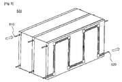
図4及び5は、本発明の様々な実施態様による冷却剤導管の、図1のバッテリーモジュールアセンブリーにおける接続を例示する典型的な図である。 4 and 5 are exemplary views illustrating connections in the battery module assembly of FIG. 1 of coolant conduits according to various embodiments of the present invention.
先ず、図4に関して、バッテリーモジュールアセンブリー400は、2個のバッテリーモジュール110及び120及び3個の冷却部材230を包含する。各冷却部材232及び242の冷却剤導管420及び410は、互いに接続されている。また、冷却剤入口430及び冷却剤出口450は、バッテリーモジュールアセンブリー400の右側の上側末端及び右側の下側末端で同じ方向に配置されている。
First, referring to FIG. 4, the
従って、液体冷却剤は、バッテリーモジュールアセンブリー400の中に、バッテリーモジュールアセンブリー400の右側の上側末端に配置された冷却剤入口430を通して導入され、第一の最も外側にあるバッテリーモジュール110の外側に配置された冷却剤導管(図には示していない)、バッテリーモジュール110と120との間の界面に配置された冷却剤導管(図には示していない)、及び第二の最も外側にあるバッテリーモジュール120の外側に配置された冷却部材232の冷却剤導管410に沿って連続的に流れ、バッテリーモジュールアセンブリー400の右側の下側末端に配置された冷却剤出口450を通して外側に排出される。
Accordingly, the liquid coolant is introduced into the
図5に関して、バッテリーモジュールアセンブリー500は、冷却剤入口510及び冷却剤出口520が、バッテリーモジュールアセンブリー500の左側部分及び右側部分に、それぞれ対向する方向で配置されるように形成されている。
Referring to FIG. 5, the
図6は、図4のバッテリーモジュールを例示する透視図である。 FIG. 6 is a perspective view illustrating the battery module of FIG.
図6及び図2に関して、バッテリーモジュール120は、8個のバッテリーセル1210がモジュールケース1220の中に、バッテリーセル1210が横方向で、各バッテリーセル1210間に隙間を置かずに積み重ねられた状態で、取り付けられる構造に形成されている。図2の冷却部材200は、最も外側にあるバッテリーセルの外側に取り付けられている。冷却部材200への熱伝導性を改良するために、バッテリーモジュール120は、少なくとも冷却部材200と接触する区域に伸びる熱伝導性プレート1230を備えている。
6 and 2, the
図7は、図4に示す熱伝導性固定部材の一つを典型的に例示する、熱伝導性固定部材の透視図を包含する側面図である。 FIG. 7 is a side view including a perspective view of a thermally conductive fixing member typically illustrating one of the thermally conductive fixing members shown in FIG.
図7及び図4に関して、熱伝導性固定部材300は、プレート310及びそのプレート310に取り付けられた弾性体を包含し、弾性体は、図4の冷却剤導管440の外側を取り囲む形状に形成される。弾性体は、その断面で片側に開口部330を有するリング320の形状に形成される。
7 and 4, the thermally conductive fixing
従って、リング320は、開口部330を通して冷却剤導管440を取り囲んだ状態で、プレート本体232の溝中に冷却剤導管を固定する。
Accordingly, the
上記の説明から明らかなように、本発明のバッテリーモジュールアセンブリーは、液体冷却剤を流す冷却剤導管を包含する冷却部材がバッテリーモジュールの外側に取り付けられ、それによって、バッテリーモジュールの冷却効率を大きく改良し、従って、バッテリーモジュールの耐用寿命及び信頼性を大きく改良する構造に形成される。 As apparent from the above description, the battery module assembly of the present invention has a cooling member including a coolant conduit for flowing a liquid coolant attached to the outside of the battery module, thereby increasing the cooling efficiency of the battery module. Therefore, it is formed into a structure that greatly improves the service life and reliability of the battery module.
また、冷却剤導管は、様々な構造に形成され、従って、バッテリーモジュールアセンブリーの冷却装置を容易に、融通性良く形成することができる。 In addition, the coolant conduit may be formed in various structures, so that the cooling device for the battery module assembly can be easily and flexibly formed.
本発明の好ましい実施態様を例示のために開示したが、当業者には明らかなように、請求項に記載する本発明の範囲及び精神から離れることなく、様々な修正、追加、及び置き換えが可能である。 While preferred embodiments of the invention have been disclosed by way of example, it will be apparent to those skilled in the art that various modifications, additions and substitutions can be made without departing from the scope and spirit of the invention as claimed. It is.
Claims (21)
複数のバッテリーモジュールと、冷却部材とを備えてなり、
前記バッテリーモジュールのそれぞれが、複数のバッテリーセルまたは単位モジュールを備えてなり、
前記複数のバッテリーセルまたは単位モジュールが、互いに直列に接続された状態で、モジュールケース中に取り付けられてなり、
前記バッテリーモジュールが互いに電気的に接続された状態で、前記バッテリーモジュールが横方向で互いに隣接して配置されてなり、
前記冷却部材が、液体冷却剤を流すための冷却剤導管を備えてなり、各バッテリーモジュールの外側に取り付けられてなり、
前記冷却部材が、一個以上の冷却剤導管が各バッテリーモジュールの外側に対応する形状に形成されたプレート本体に取り付けられた構造を有するように形成されてなり、
前記プレート本体が、前記プレート本体の外側に、各冷却剤導管の幅に対応する連続溝を備え、各冷却剤導管が、前記溝の中に固定して配置されてなり、
各バッテリーモジュールと接触するように形成された一個以上の熱伝導性固定部材が各冷却剤導管に接続されてなり、
各バッテリーモジュールから前記冷却部材への熱伝導性を改良してなる、バッテリーモジュールアセンブリー。 A battery module assembly,
Comprising a plurality of battery modules and a cooling member;
Each of the battery modules comprises a plurality of battery cells or unit modules,
The plurality of battery cells or unit modules are mounted in a module case in a state of being connected in series with each other,
With the battery modules electrically connected to each other, the battery modules are arranged adjacent to each other in the lateral direction,
Wherein the cooling member is made provided with a coolant conduit for flowing a liquid coolant, Ri name attached to the outside of each battery module,
The cooling member has a structure in which one or more coolant conduits are attached to a plate body formed in a shape corresponding to the outside of each battery module;
The plate body includes a continuous groove corresponding to the width of each coolant conduit outside the plate body, and each coolant conduit is fixedly disposed in the groove;
One or more thermally conductive fixing members formed to contact each battery module are connected to each coolant conduit;
A battery module assembly obtained by improving thermal conductivity from each battery module to the cooling member .
前記弾性体が、各冷却剤導管に対応する形状に形成されてなる、請求項6に記載のバッテリーモジュールアセンブリー。 Each thermally conductive fixing member comprises a plate and an elastic body attached to the plate,
The battery module assembly according to claim 6, wherein the elastic body is formed in a shape corresponding to each coolant conduit.
前記冷却部材の冷却剤導管が互いに接続され、前記冷却部材の一つを通して導入された冷却剤が他の冷却部材に連続的に流れるものである、請求項1に記載のバッテリーモジュールアセンブリー。 The battery module assembly comprises two or more cooling members;
The battery module assembly of claim 1, wherein the coolant conduits of the cooling member are connected to each other, and the coolant introduced through one of the cooling members flows continuously to the other cooling member.
バッテリーセルまたはバッテリーモジュールの外側に取り付けられ、前記バッテリーセルまたは前記バッテリーモジュールを冷却するものであり、
前記冷却部材が、前記バッテリーセルまたは前記バッテリーモジュールの外側に対応する形状に形成されたプレート本体に連続溝が形成されてなり、かつ、液体冷却剤を流す冷却剤導管が前記溝の中に固定して取り付けられる構造を有するように形成されてなり、
前記バッテリーセルまたは前記バッテリーモジュールに接触するように形成された一個以上の熱伝導性固定部材が前記冷却剤導管に接続され、前記バッテリーセルまたは前記バッテリーモジュールから前記冷却部材への熱伝導性が改良されてなる、冷却部材。 A cooling member,
It is attached to the outside of the battery cell or the battery module, and cools the battery cell or the battery module.
The cooling member has a continuous groove formed in a plate body formed in a shape corresponding to the outside of the battery cell or the battery module, and a coolant conduit for flowing a liquid coolant is fixed in the groove. Formed to have a structure to be attached,
One or more heat conductive fixing members formed to contact the battery cell or the battery module are connected to the coolant conduit to improve heat conductivity from the battery cell or the battery module to the cooling member. A cooling member.
Applications Claiming Priority (3)
| Application Number | Priority Date | Filing Date | Title |
|---|---|---|---|
| KR10-2008-0100635 | 2008-10-14 | ||
| KR1020080100635A KR101112442B1 (en) | 2008-10-14 | 2008-10-14 | Battery Module Assembly of Improved Cooling Efficiency |
| PCT/KR2009/005406 WO2010044553A2 (en) | 2008-10-14 | 2009-09-23 | Battery module assembly with improved cooling efficiency |
Publications (2)
| Publication Number | Publication Date |
|---|---|
| JP2012506106A JP2012506106A (en) | 2012-03-08 |
| JP5431486B2 true JP5431486B2 (en) | 2014-03-05 |
Family
ID=42107012
Family Applications (1)
| Application Number | Title | Priority Date | Filing Date |
|---|---|---|---|
| JP2011530935A Active JP5431486B2 (en) | 2008-10-14 | 2009-09-23 | Battery module assembly with improved cooling efficiency |
Country Status (8)
| Country | Link |
|---|---|
| US (1) | US8846233B2 (en) |
| EP (1) | EP2337143B1 (en) |
| JP (1) | JP5431486B2 (en) |
| KR (1) | KR101112442B1 (en) |
| CN (2) | CN104218272B (en) |
| ES (1) | ES2549907T3 (en) |
| RU (1) | RU2479895C2 (en) |
| WO (1) | WO2010044553A2 (en) |
Families Citing this family (92)
| Publication number | Priority date | Publication date | Assignee | Title |
|---|---|---|---|---|
| KR101205181B1 (en) | 2010-05-18 | 2012-11-27 | 주식회사 엘지화학 | Cooling Member of Novel Structure and Battery Module Employed with the Same |
| WO2012023753A2 (en) * | 2010-08-16 | 2012-02-23 | 주식회사 엘지화학 | Battery module with compact structure and excellent heat radiation characteristics, and medium- or large-sized battery pack |
| KR101206272B1 (en) * | 2010-11-22 | 2012-11-30 | 주식회사 한국쿨러 | Heat sink of battery cell for electric vehicle and battery cell module using the same |
| KR101293211B1 (en) * | 2010-12-28 | 2013-08-05 | 주식회사 엘지화학 | Battery module container, battery module temperature control apparatus and power storage system having them |
| PL2650960T3 (en) | 2011-01-26 | 2020-05-18 | Lg Chem, Ltd. | Cooling element having improved assembly productivity and battery modules including same |
| CN103380534B (en) * | 2011-02-22 | 2016-01-20 | 株式会社Lg化学 | Cooling member with improved cooling efficiency and battery module using same |
| KR101367210B1 (en) * | 2011-12-09 | 2014-02-27 | 대한칼소닉주식회사 | Battery cell of heat sink unit |
| EP2801119A4 (en) * | 2012-01-05 | 2015-07-22 | Electrovaya Inc | FLUID COOLED BATTERY MODULE CONTAINING BATTERY ELEMENTS |
| KR20130118145A (en) * | 2012-04-19 | 2013-10-29 | 삼성에스디아이 주식회사 | Battery pack |
| DE102012015816B4 (en) * | 2012-08-10 | 2023-10-26 | Dr. Ing. H.C. F. Porsche Ag | Motor vehicle battery |
| DE102012214783A1 (en) * | 2012-08-20 | 2014-02-20 | Behr Gmbh & Co. Kg | Heat exchanger for a battery unit |
| DE102012109728B4 (en) * | 2012-10-12 | 2022-11-10 | Dr. Ing. H.C. F. Porsche Aktiengesellschaft | Support structure of a motor vehicle and motor vehicle |
| CN105359330A (en) * | 2013-03-28 | 2016-02-24 | 日立汽车系统株式会社 | Battery module |
| KR102187744B1 (en) * | 2013-05-24 | 2020-12-07 | 엘지전자 주식회사 | Battery cell assembly and cell module for electronic vehicles |
| JP6214985B2 (en) * | 2013-09-20 | 2017-10-18 | 株式会社東芝 | Battery pack, battery pack and automobile |
| US9566954B2 (en) * | 2014-03-10 | 2017-02-14 | Max Moskowitz | Vehicular accessory |
| US10549729B2 (en) | 2014-03-10 | 2020-02-04 | Max Moskowitz | Vehicular accessory |
| CN103840234A (en) * | 2014-03-14 | 2014-06-04 | 吉林大学 | Battery pack liquid flow laminated layer heat-exchanging flat pipe bundle structure and method |
| CN104319431A (en) * | 2014-10-17 | 2015-01-28 | 广东亿纬赛恩斯新能源系统有限公司 | Battery module and cooling method thereof |
| US9627724B2 (en) * | 2014-12-04 | 2017-04-18 | Lg Chem, Ltd. | Battery pack having a cooling plate assembly |
| US9995535B2 (en) | 2015-06-30 | 2018-06-12 | Faraday&Future Inc. | Heat pipe for vehicle energy-storage systems |
| US10505163B2 (en) | 2015-06-30 | 2019-12-10 | Faraday & Future Inc. | Heat exchanger for vehicle energy-storage systems |
| CN104900940B (en) * | 2015-07-02 | 2018-05-15 | 张哲群 | Battery pack temperature control system and method |
| DE102015008510A1 (en) * | 2015-07-03 | 2017-01-05 | Man Truck & Bus Ag | Motor vehicle battery |
| CN104916881B (en) * | 2015-07-07 | 2017-01-25 | 东莞市美尼电池有限公司 | Roller heat dissipation lithium battery pack |
| US20170088007A1 (en) * | 2015-09-25 | 2017-03-30 | Atieva, Inc. | External Auxiliary Thermal Management System for an Electric Vehicle |
| KR102051109B1 (en) * | 2015-10-08 | 2019-12-02 | 주식회사 엘지화학 | Battery Module |
| JP7034419B2 (en) * | 2015-12-14 | 2022-03-14 | エルジー エナジー ソリューション リミテッド | Battery module, battery pack containing the battery module and automobile including the battery pack |
| CN114824671A (en) * | 2016-01-29 | 2022-07-29 | 法拉第未来公司 | Battery pack for vehicle energy storage system |
| KR102562682B1 (en) | 2016-05-25 | 2023-08-03 | 삼성에스디아이 주식회사 | Battery module |
| WO2018033880A2 (en) | 2016-08-17 | 2018-02-22 | Shape Corp. | Battery support and protection structure for a vehicle |
| CN106992273B (en) * | 2016-09-21 | 2018-09-11 | 比亚迪股份有限公司 | Power battery pack |
| KR102130818B1 (en) * | 2016-09-28 | 2020-07-06 | 주식회사 엘지화학 | Secondary battery module having cooling passage, fabrication method and frame assembly for the same |
| CN106450568B (en) * | 2016-10-09 | 2019-07-02 | 浙江吉利控股集团有限公司 | A power battery pack thermal management system |
| US10581125B2 (en) | 2016-11-02 | 2020-03-03 | Lg Chem, Ltd. | Battery system having a metallic end plate with thermally conductive adhesive portions thereon |
| FR3058575A1 (en) | 2016-11-07 | 2018-05-11 | Peugeot Citroen Automobiles Sa | BATTERY WITH ELECTROCHEMICAL CELL MODULES (S) SEPARATED BY EXTERNAL EXCHANGE PLATES, AND SYSTEM THEREFOR |
| WO2018127832A1 (en) | 2017-01-04 | 2018-07-12 | Shape Corp. | Vehicle battery tray structure with nodal modularity |
| CN106532192B (en) * | 2017-01-17 | 2024-05-07 | 华霆(合肥)动力技术有限公司 | Distributed thermal management system and battery |
| GB2561211B (en) * | 2017-04-05 | 2019-09-04 | Siemens Ag | Cooling system |
| WO2018213306A1 (en) | 2017-05-16 | 2018-11-22 | Shape Corp. | Vehicle battery tray having tub-based component |
| US10483510B2 (en) | 2017-05-16 | 2019-11-19 | Shape Corp. | Polarized battery tray for a vehicle |
| US11211656B2 (en) | 2017-05-16 | 2021-12-28 | Shape Corp. | Vehicle battery tray with integrated battery retention and support feature |
| JP6969913B2 (en) * | 2017-06-26 | 2021-11-24 | 株式会社東芝 | Battery device |
| KR102258816B1 (en) | 2017-06-27 | 2021-05-31 | 주식회사 엘지에너지솔루션 | Battery Module |
| BR102018014050B1 (en) * | 2017-07-27 | 2023-12-26 | Toyota Jidosha Kabushiki Kaisha | BATTERY COOLING SYSTEM |
| KR102273881B1 (en) * | 2017-08-14 | 2021-07-06 | 주식회사 엘지에너지솔루션 | Battery pack having improved temperature control performance |
| CN107634161A (en) * | 2017-09-07 | 2018-01-26 | 河南新太行电源股份有限公司 | Battery case and battery with radiating tube |
| US12347879B2 (en) | 2017-09-13 | 2025-07-01 | Shape Corp. | Vehicle battery tray with tubular peripheral wall |
| US11088412B2 (en) | 2017-09-13 | 2021-08-10 | Shape Corp. | Vehicle battery tray with tubular peripheral wall |
| CN107611288A (en) * | 2017-09-15 | 2018-01-19 | 河南新太行电源股份有限公司 | A kind of battery case and battery with heat radiation sandwich layer |
| KR20190032843A (en) | 2017-09-20 | 2019-03-28 | 에스케이이노베이션 주식회사 | Battery Module for Secondary Battery and Battery Pack having the Same |
| CN111201155A (en) | 2017-10-04 | 2020-05-26 | 形状集团 | Battery Tray Floor Assembly for Electric Vehicles |
| KR102280096B1 (en) | 2017-10-17 | 2021-07-21 | 주식회사 엘지에너지솔루션 | Battery pack having function to block the inflow of leakage coolant |
| CN107887544A (en) * | 2017-11-10 | 2018-04-06 | 广东欧珀移动通信有限公司 | A battery and an electronic device |
| KR102410862B1 (en) * | 2017-11-10 | 2022-06-21 | 에스케이온 주식회사 | Battery module |
| KR102198001B1 (en) | 2017-12-11 | 2021-01-04 | 삼성에스디아이 주식회사 | Battery module |
| KR102554939B1 (en) * | 2018-01-08 | 2023-07-11 | 현대자동차주식회사 | Cooling apparatus for battery |
| CN109585970B (en) * | 2018-02-07 | 2024-04-26 | 骆驼集团武汉光谷研发中心有限公司 | Pressure-resistant liquid-cooled radiating fin |
| CN112055898A (en) | 2018-03-01 | 2020-12-08 | 形状集团 | Cooling system integrated with vehicle battery tray |
| JP7098355B2 (en) * | 2018-03-06 | 2022-07-11 | 株式会社東芝 | Battery module and assembled battery |
| US11688910B2 (en) | 2018-03-15 | 2023-06-27 | Shape Corp. | Vehicle battery tray having tub-based component |
| KR102569935B1 (en) * | 2018-03-26 | 2023-08-23 | 에이치그린파워 주식회사 | Battery module assembly structure and the method to use cooling blocks |
| EP3584877A1 (en) | 2018-05-16 | 2019-12-25 | Samsung SDI Co., Ltd. | Battery pack comprising a frame profile with integral coolant circuit elements |
| KR102361268B1 (en) | 2018-07-10 | 2022-02-09 | 주식회사 엘지에너지솔루션 | Cooling system for battery pack of electric vehicle and cooling method for battery pack system of electric vehicle using the same |
| US12183902B2 (en) | 2018-07-18 | 2024-12-31 | Gopro, Inc. | Apparatus for battery cooling considering battery expansion |
| DE102018212627A1 (en) * | 2018-07-27 | 2020-01-30 | Mahle International Gmbh | accumulator |
| CN110828929A (en) * | 2018-08-08 | 2020-02-21 | 天臣新能源有限公司 | Novel cylindrical electric core liquid cooling module |
| CN112585803B (en) * | 2018-09-14 | 2023-12-29 | 三菱化学株式会社 | Filling components and battery packs |
| KR102389911B1 (en) | 2018-09-17 | 2022-04-21 | 주식회사 엘지에너지솔루션 | Battery Module Having Module Housing |
| KR102358425B1 (en) * | 2018-09-18 | 2022-02-03 | 주식회사 엘지에너지솔루션 | Battery module |
| CN109301115A (en) * | 2018-10-08 | 2019-02-01 | 马鞍山沐及信息科技有限公司 | A kind of new energy car battery water cooling casing |
| EP3863881A1 (en) | 2018-10-12 | 2021-08-18 | Volvo Truck Corporation | A battery pack arrangement for a vehicle |
| US10763556B2 (en) | 2018-12-10 | 2020-09-01 | Volvo Car Corporation | Vehicle battery assembly utilizing side cooling plates |
| IT201800020902A1 (en) * | 2018-12-21 | 2020-06-21 | Magneti Marelli Spa | COOLING MODULE OF AN ELECTRICITY STORAGE SYSTEM FOR A VEHICLE WITH ELECTRIC PROPULSION |
| CN111384470A (en) * | 2020-02-21 | 2020-07-07 | 威睿电动汽车技术(苏州)有限公司 | Battery package cooling system and vehicle |
| KR102846582B1 (en) * | 2019-09-30 | 2025-08-13 | 에스케이온 주식회사 | Battery Module |
| KR102821616B1 (en) | 2020-04-28 | 2025-06-16 | 주식회사 엘지에너지솔루션 | Battery pack and device including the same |
| RU2737037C1 (en) * | 2020-07-03 | 2020-11-25 | Общество с ограниченной ответственностью "Смартер" | Electrochemical device and battery |
| KR102869898B1 (en) | 2020-09-01 | 2025-10-14 | 삼성전자주식회사 | Method and apparatus estimating a state of battery |
| KR102481835B1 (en) * | 2020-12-23 | 2022-12-26 | 고려대학교 산학협력단 | Battery cell cooling structure |
| US12078682B2 (en) | 2021-03-03 | 2024-09-03 | Samsung Electronics Co., Ltd. | Method and apparatus for estimating state of battery |
| KR20220133660A (en) | 2021-03-25 | 2022-10-05 | 에이치그린파워 주식회사 | Battery System Having Double Coolant Flow type Water Cooling Battery Module and Battery Module Cooling Control Method Thereof |
| KR20220169832A (en) * | 2021-06-21 | 2022-12-28 | 주식회사 엘지에너지솔루션 | Battery module and battery pack including the same and vehicle including the same |
| FR3124348B1 (en) * | 2021-06-22 | 2023-10-20 | Valeo Systemes Thermiques | Thermal regulation device for electronic system |
| US20230033307A1 (en) * | 2021-08-01 | 2023-02-02 | Vanderhall Motor Works, Inc. | Electric vehicle battery heat exchange system |
| CN215644656U (en) * | 2021-08-30 | 2022-01-25 | 重庆电哥科技(集团)有限公司 | Vehicle-mounted energy storage power supply |
| KR102885238B1 (en) | 2021-09-08 | 2025-11-12 | 삼성전자주식회사 | Electronic device for estimating battery state and method for operating method thereof |
| EP4254605A1 (en) * | 2022-02-21 | 2023-10-04 | Contemporary Amperex Technology Co., Limited | Battery, electric device, and method and device for preparing battery |
| FR3134655B1 (en) | 2022-04-13 | 2024-03-01 | Psa Automobiles Sa | LIGHTWEIGHT HEAT EXCHANGE DEVICE FOR A BATTERY OF A SYSTEM |
| WO2023240462A1 (en) * | 2022-06-14 | 2023-12-21 | 宁德时代新能源科技股份有限公司 | Battery and electric device |
| WO2024059835A2 (en) * | 2022-09-18 | 2024-03-21 | Proterra Operating Company, Inc. | Coolant manifold for battery pack |
| US12427888B2 (en) * | 2022-09-22 | 2025-09-30 | GM Global Technology Operations LLC | DCFC smart cooling strategy |
Family Cites Families (30)
| Publication number | Priority date | Publication date | Assignee | Title |
|---|---|---|---|---|
| US2273244A (en) | 1940-04-03 | 1942-02-17 | Electric Storage Battery Co | Storage battery cell |
| US4500612A (en) * | 1982-04-21 | 1985-02-19 | Mitsubishi Denki Kabushiki Kaisha | Temperature control device for a fuel cell |
| US4574112A (en) * | 1983-12-23 | 1986-03-04 | United Technologies Corporation | Cooling system for electrochemical fuel cell |
| RU2031491C1 (en) * | 1992-05-18 | 1995-03-20 | Юрий Вячеславович Николаев | Method of thermal control over high-temperature storage battery |
| US5356735A (en) * | 1993-05-10 | 1994-10-18 | General Motors Corporation | Heated/cooled battery |
| JPH08111244A (en) | 1994-10-12 | 1996-04-30 | Nissan Motor Co Ltd | Stacked battery device |
| JPH09245809A (en) * | 1996-03-07 | 1997-09-19 | Mitsubishi Electric Corp | Fuel cell cooling system |
| JP3312852B2 (en) * | 1996-09-26 | 2002-08-12 | 松下電器産業株式会社 | Battery power supply |
| KR100422175B1 (en) | 1997-01-13 | 2004-03-10 | 오보닉 배터리 컴퍼니, 아이엔씨. | Fluid cooled battery-pack system |
| JP3724103B2 (en) * | 1997-03-11 | 2005-12-07 | トヨタ自動車株式会社 | Battery assembly |
| US6087036A (en) * | 1997-07-25 | 2000-07-11 | 3M Innovative Properties Company | Thermal management system and method for a solid-state energy storing device |
| FR2779872B1 (en) * | 1998-06-11 | 2000-08-04 | Alsthom Cge Alcatel | MONOBLOCK BATTERY COMPRISING A THERMAL EXCHANGE DEVICE BY CIRCULATION OF A FLUID |
| JP2000348781A (en) * | 1999-06-04 | 2000-12-15 | Japan Storage Battery Co Ltd | Non-aqueous electrolyte battery |
| AU2001291250A1 (en) * | 2000-09-26 | 2002-04-08 | Ovonic Battery Company, Inc. | Monoblock battery assembly with cross-flow cooling |
| JP4516229B2 (en) * | 2001-03-06 | 2010-08-04 | 本田技研工業株式会社 | Solid polymer cell assembly |
| JP3770539B2 (en) | 2001-10-25 | 2006-04-26 | 松下電器産業株式会社 | Storage battery |
| US6512347B1 (en) * | 2001-10-18 | 2003-01-28 | General Motors Corporation | Battery having an integral cooling system |
| DE10214366B4 (en) * | 2002-03-30 | 2017-03-16 | Robert Bosch Gmbh | measuring arrangement |
| JP4525144B2 (en) | 2004-04-02 | 2010-08-18 | ソニー株式会社 | Solid-state imaging device and manufacturing method thereof |
| JP4490719B2 (en) | 2004-04-02 | 2010-06-30 | 東芝モバイルディスプレイ株式会社 | Liquid crystal display |
| JP4595433B2 (en) | 2004-08-05 | 2010-12-08 | トヨタ自動車株式会社 | Assembled battery |
| KR100853621B1 (en) * | 2004-10-26 | 2008-08-25 | 주식회사 엘지화학 | Battery pack cooling system |
| JP2006216303A (en) * | 2005-02-02 | 2006-08-17 | Denso Corp | Cooling structure of heat radiating unit |
| KR20060102851A (en) * | 2005-03-25 | 2006-09-28 | 삼성에스디아이 주식회사 | Secondary battery module |
| RU2275764C1 (en) * | 2005-08-08 | 2006-04-27 | Сергей Анатольевич Ермаков | Thermal pipe with forced liquid circulation and thermal pipe for cooling notebooks |
| KR101029021B1 (en) | 2005-12-02 | 2011-04-14 | 주식회사 엘지화학 | High Cooling Battery Module |
| KR100870457B1 (en) | 2006-05-22 | 2008-11-25 | 주식회사 엘지화학 | Battery module |
| KR100896131B1 (en) | 2006-05-22 | 2009-05-08 | 주식회사 엘지화학 | Medium and large battery module |
| KR100899040B1 (en) * | 2006-11-15 | 2009-05-26 | 박철우 | Radiator |
| DE102006059989A1 (en) * | 2006-12-19 | 2008-06-26 | Daimler Ag | Arrangement for cooling battery, has multiple individual cells, which are assembled together for battery and individual cells have cylindrical housing form |
-
2008
- 2008-10-14 KR KR1020080100635A patent/KR101112442B1/en active Active
-
2009
- 2009-09-23 ES ES09820703.8T patent/ES2549907T3/en active Active
- 2009-09-23 US US13/122,210 patent/US8846233B2/en active Active
- 2009-09-23 WO PCT/KR2009/005406 patent/WO2010044553A2/en not_active Ceased
- 2009-09-23 CN CN201410356806.4A patent/CN104218272B/en active Active
- 2009-09-23 RU RU2011112810/07A patent/RU2479895C2/en active
- 2009-09-23 JP JP2011530935A patent/JP5431486B2/en active Active
- 2009-09-23 EP EP09820703.8A patent/EP2337143B1/en active Active
- 2009-09-23 CN CN2009801393467A patent/CN102171884A/en active Pending
Also Published As
| Publication number | Publication date |
|---|---|
| EP2337143A2 (en) | 2011-06-22 |
| JP2012506106A (en) | 2012-03-08 |
| RU2011112810A (en) | 2012-11-27 |
| US20120009457A1 (en) | 2012-01-12 |
| CN104218272B (en) | 2018-05-08 |
| WO2010044553A3 (en) | 2010-07-15 |
| KR101112442B1 (en) | 2012-02-20 |
| EP2337143B1 (en) | 2015-08-05 |
| WO2010044553A2 (en) | 2010-04-22 |
| EP2337143A4 (en) | 2013-12-18 |
| KR20100041452A (en) | 2010-04-22 |
| US8846233B2 (en) | 2014-09-30 |
| CN104218272A (en) | 2014-12-17 |
| RU2479895C2 (en) | 2013-04-20 |
| ES2549907T3 (en) | 2015-11-03 |
| CN102171884A (en) | 2011-08-31 |
Similar Documents
| Publication | Publication Date | Title |
|---|---|---|
| JP5431486B2 (en) | Battery module assembly with improved cooling efficiency | |
| JP5540114B2 (en) | Medium or large battery pack with improved cooling efficiency | |
| US11139515B2 (en) | Battery module having heat conduction pad | |
| JP5579740B2 (en) | Battery pack with new air cooling structure (medium or large) | |
| JP5625115B2 (en) | A small-sized battery module having excellent heat radiation characteristics, and a medium- or large-sized battery pack using the battery module | |
| JP6109210B2 (en) | Battery module with excellent cooling efficiency and compact structure, and medium or large battery pack | |
| KR102762539B1 (en) | Busbar Frame Assembly and Battery module including the same | |
| JP5779793B2 (en) | Battery module having excellent heat dissipation capability and battery pack using the same | |
| KR101910244B1 (en) | Battery Module Having Improved Cooling Performance | |
| EP2763214B1 (en) | Battery module | |
| JP5307250B2 (en) | Battery module having cooling means, and (medium or large) battery pack including the same | |
| JP5782113B2 (en) | Newly structured cooling member and battery module using the cooling member | |
| JP5577459B2 (en) | Cooling member having compact structure and excellent stability, and battery module having the same | |
| KR101787460B1 (en) | Scalable battery module | |
| JP5175203B2 (en) | Battery pack heat exchanger using thermoelectric elements | |
| JP5526289B2 (en) | Battery pack with new structure | |
| KR102026386B1 (en) | Battery module |
Legal Events
| Date | Code | Title | Description |
|---|---|---|---|
| A131 | Notification of reasons for refusal |
Free format text: JAPANESE INTERMEDIATE CODE: A131 Effective date: 20130416 |
|
| A601 | Written request for extension of time |
Free format text: JAPANESE INTERMEDIATE CODE: A601 Effective date: 20130710 |
|
| A602 | Written permission of extension of time |
Free format text: JAPANESE INTERMEDIATE CODE: A602 Effective date: 20130718 |
|
| A601 | Written request for extension of time |
Free format text: JAPANESE INTERMEDIATE CODE: A601 Effective date: 20130808 |
|
| A602 | Written permission of extension of time |
Free format text: JAPANESE INTERMEDIATE CODE: A602 Effective date: 20130815 |
|
| A521 | Request for written amendment filed |
Free format text: JAPANESE INTERMEDIATE CODE: A523 Effective date: 20130917 |
|
| TRDD | Decision of grant or rejection written | ||
| A01 | Written decision to grant a patent or to grant a registration (utility model) |
Free format text: JAPANESE INTERMEDIATE CODE: A01 Effective date: 20131108 |
|
| A61 | First payment of annual fees (during grant procedure) |
Free format text: JAPANESE INTERMEDIATE CODE: A61 Effective date: 20131204 |
|
| R150 | Certificate of patent or registration of utility model |
Free format text: JAPANESE INTERMEDIATE CODE: R150 Ref document number: 5431486 Country of ref document: JP Free format text: JAPANESE INTERMEDIATE CODE: R150 |
|
| RD02 | Notification of acceptance of power of attorney |
Free format text: JAPANESE INTERMEDIATE CODE: R3D02 |
|
| R250 | Receipt of annual fees |
Free format text: JAPANESE INTERMEDIATE CODE: R250 |
|
| R250 | Receipt of annual fees |
Free format text: JAPANESE INTERMEDIATE CODE: R250 |
|
| R250 | Receipt of annual fees |
Free format text: JAPANESE INTERMEDIATE CODE: R250 |
|
| R250 | Receipt of annual fees |
Free format text: JAPANESE INTERMEDIATE CODE: R250 |
|
| R250 | Receipt of annual fees |
Free format text: JAPANESE INTERMEDIATE CODE: R250 |
|
| R250 | Receipt of annual fees |
Free format text: JAPANESE INTERMEDIATE CODE: R250 |
|
| S111 | Request for change of ownership or part of ownership |
Free format text: JAPANESE INTERMEDIATE CODE: R313111 |
|
| R350 | Written notification of registration of transfer |
Free format text: JAPANESE INTERMEDIATE CODE: R350 |
|
| R250 | Receipt of annual fees |
Free format text: JAPANESE INTERMEDIATE CODE: R250 |
|
| R250 | Receipt of annual fees |
Free format text: JAPANESE INTERMEDIATE CODE: R250 |
|
| R250 | Receipt of annual fees |
Free format text: JAPANESE INTERMEDIATE CODE: R250 |
|
| R250 | Receipt of annual fees |
Free format text: JAPANESE INTERMEDIATE CODE: R250 |