JP5427607B2 - Improvements in and related to drive mechanisms suitable for use in drug delivery devices - Google Patents
Improvements in and related to drive mechanisms suitable for use in drug delivery devices Download PDFInfo
- Publication number
- JP5427607B2 JP5427607B2 JP2009536636A JP2009536636A JP5427607B2 JP 5427607 B2 JP5427607 B2 JP 5427607B2 JP 2009536636 A JP2009536636 A JP 2009536636A JP 2009536636 A JP2009536636 A JP 2009536636A JP 5427607 B2 JP5427607 B2 JP 5427607B2
- Authority
- JP
- Japan
- Prior art keywords
- piston rod
- drive member
- lever
- drug delivery
- housing
- Prior art date
- Legal status (The legal status is an assumption and is not a legal conclusion. Google has not performed a legal analysis and makes no representation as to the accuracy of the status listed.)
- Expired - Fee Related
Links
- 238000012377 drug delivery Methods 0.000 title claims description 66
- 230000007246 mechanism Effects 0.000 title claims description 47
- 230000000712 assembly Effects 0.000 claims description 2
- 238000000429 assembly Methods 0.000 claims description 2
- 238000004519 manufacturing process Methods 0.000 claims description 2
- 230000033001 locomotion Effects 0.000 description 82
- 238000007373 indentation Methods 0.000 description 35
- 239000003814 drug Substances 0.000 description 17
- 229940079593 drug Drugs 0.000 description 14
- 230000000007 visual effect Effects 0.000 description 10
- 230000003993 interaction Effects 0.000 description 8
- 230000008901 benefit Effects 0.000 description 6
- NOESYZHRGYRDHS-UHFFFAOYSA-N insulin Chemical compound N1C(=O)C(NC(=O)C(CCC(N)=O)NC(=O)C(CCC(O)=O)NC(=O)C(C(C)C)NC(=O)C(NC(=O)CN)C(C)CC)CSSCC(C(NC(CO)C(=O)NC(CC(C)C)C(=O)NC(CC=2C=CC(O)=CC=2)C(=O)NC(CCC(N)=O)C(=O)NC(CC(C)C)C(=O)NC(CCC(O)=O)C(=O)NC(CC(N)=O)C(=O)NC(CC=2C=CC(O)=CC=2)C(=O)NC(CSSCC(NC(=O)C(C(C)C)NC(=O)C(CC(C)C)NC(=O)C(CC=2C=CC(O)=CC=2)NC(=O)C(CC(C)C)NC(=O)C(C)NC(=O)C(CCC(O)=O)NC(=O)C(C(C)C)NC(=O)C(CC(C)C)NC(=O)C(CC=2NC=NC=2)NC(=O)C(CO)NC(=O)CNC2=O)C(=O)NCC(=O)NC(CCC(O)=O)C(=O)NC(CCCNC(N)=N)C(=O)NCC(=O)NC(CC=3C=CC=CC=3)C(=O)NC(CC=3C=CC=CC=3)C(=O)NC(CC=3C=CC(O)=CC=3)C(=O)NC(C(C)O)C(=O)N3C(CCC3)C(=O)NC(CCCCN)C(=O)NC(C)C(O)=O)C(=O)NC(CC(N)=O)C(O)=O)=O)NC(=O)C(C(C)CC)NC(=O)C(CO)NC(=O)C(C(C)O)NC(=O)C1CSSCC2NC(=O)C(CC(C)C)NC(=O)C(NC(=O)C(CCC(N)=O)NC(=O)C(CC(N)=O)NC(=O)C(NC(=O)C(N)CC=1C=CC=CC=1)C(C)C)CC1=CN=CN1 NOESYZHRGYRDHS-UHFFFAOYSA-N 0.000 description 6
- 239000000825 pharmaceutical preparation Substances 0.000 description 5
- 229940127557 pharmaceutical product Drugs 0.000 description 5
- 238000003825 pressing Methods 0.000 description 5
- 102000004877 Insulin Human genes 0.000 description 3
- 108090001061 Insulin Proteins 0.000 description 3
- 238000002347 injection Methods 0.000 description 3
- 239000007924 injection Substances 0.000 description 3
- 229940125396 insulin Drugs 0.000 description 3
- 239000000463 material Substances 0.000 description 3
- 102000018997 Growth Hormone Human genes 0.000 description 2
- 108010051696 Growth Hormone Proteins 0.000 description 2
- 230000009471 action Effects 0.000 description 2
- 150000001875 compounds Chemical class 0.000 description 2
- 230000008878 coupling Effects 0.000 description 2
- 238000010168 coupling process Methods 0.000 description 2
- 238000005859 coupling reaction Methods 0.000 description 2
- 239000000428 dust Substances 0.000 description 2
- 239000000122 growth hormone Substances 0.000 description 2
- 239000003055 low molecular weight heparin Substances 0.000 description 2
- 229940127215 low-molecular weight heparin Drugs 0.000 description 2
- 230000000717 retained effect Effects 0.000 description 2
- WQZGKKKJIJFFOK-GASJEMHNSA-N Glucose Natural products OC[C@H]1OC(O)[C@H](O)[C@@H](O)[C@@H]1O WQZGKKKJIJFFOK-GASJEMHNSA-N 0.000 description 1
- HTTJABKRGRZYRN-UHFFFAOYSA-N Heparin Chemical compound OC1C(NC(=O)C)C(O)OC(COS(O)(=O)=O)C1OC1C(OS(O)(=O)=O)C(O)C(OC2C(C(OS(O)(=O)=O)C(OC3C(C(O)C(O)C(O3)C(O)=O)OS(O)(=O)=O)C(CO)O2)NS(O)(=O)=O)C(C(O)=O)O1 HTTJABKRGRZYRN-UHFFFAOYSA-N 0.000 description 1
- 239000008280 blood Substances 0.000 description 1
- 210000004369 blood Anatomy 0.000 description 1
- 239000000356 contaminant Substances 0.000 description 1
- 238000001125 extrusion Methods 0.000 description 1
- 239000008103 glucose Substances 0.000 description 1
- 229960002897 heparin Drugs 0.000 description 1
- 229920000669 heparin Polymers 0.000 description 1
- 239000007788 liquid Substances 0.000 description 1
- IBIKHMZPHNKTHM-RDTXWAMCSA-N merck compound 25 Chemical compound C1C[C@@H](C(O)=O)[C@H](O)CN1C(C1=C(F)C=CC=C11)=NN1C(=O)C1=C(Cl)C=CC=C1C1CC1 IBIKHMZPHNKTHM-RDTXWAMCSA-N 0.000 description 1
- 238000000034 method Methods 0.000 description 1
- 239000008194 pharmaceutical composition Substances 0.000 description 1
- 230000001766 physiological effect Effects 0.000 description 1
- 238000004064 recycling Methods 0.000 description 1
- 230000003252 repetitive effect Effects 0.000 description 1
- 239000000243 solution Substances 0.000 description 1
- 239000000725 suspension Substances 0.000 description 1
Images


Classifications
-
- A—HUMAN NECESSITIES
- A61—MEDICAL OR VETERINARY SCIENCE; HYGIENE
- A61M—DEVICES FOR INTRODUCING MEDIA INTO, OR ONTO, THE BODY; DEVICES FOR TRANSDUCING BODY MEDIA OR FOR TAKING MEDIA FROM THE BODY; DEVICES FOR PRODUCING OR ENDING SLEEP OR STUPOR
- A61M5/00—Devices for bringing media into the body in a subcutaneous, intra-vascular or intramuscular way; Accessories therefor, e.g. filling or cleaning devices, arm-rests
- A61M5/178—Syringes
- A61M5/31—Details
- A61M5/315—Pistons; Piston-rods; Guiding, blocking or restricting the movement of the rod or piston; Appliances on the rod for facilitating dosing ; Dosing mechanisms
- A61M5/31565—Administration mechanisms, i.e. constructional features, modes of administering a dose
- A61M5/31576—Constructional features or modes of drive mechanisms for piston rods
- A61M5/31578—Constructional features or modes of drive mechanisms for piston rods based on axial translation, i.e. components directly operatively associated and axially moved with plunger rod
-
- A—HUMAN NECESSITIES
- A61—MEDICAL OR VETERINARY SCIENCE; HYGIENE
- A61M—DEVICES FOR INTRODUCING MEDIA INTO, OR ONTO, THE BODY; DEVICES FOR TRANSDUCING BODY MEDIA OR FOR TAKING MEDIA FROM THE BODY; DEVICES FOR PRODUCING OR ENDING SLEEP OR STUPOR
- A61M5/00—Devices for bringing media into the body in a subcutaneous, intra-vascular or intramuscular way; Accessories therefor, e.g. filling or cleaning devices, arm-rests
- A61M5/178—Syringes
- A61M5/31—Details
- A61M5/315—Pistons; Piston-rods; Guiding, blocking or restricting the movement of the rod or piston; Appliances on the rod for facilitating dosing ; Dosing mechanisms
- A61M5/31533—Dosing mechanisms, i.e. setting a dose
- A61M5/31545—Setting modes for dosing
- A61M5/31548—Mechanically operated dose setting member
- A61M5/31555—Mechanically operated dose setting member by purely axial movement of dose setting member, e.g. during setting or filling of a syringe
-
- A—HUMAN NECESSITIES
- A61—MEDICAL OR VETERINARY SCIENCE; HYGIENE
- A61M—DEVICES FOR INTRODUCING MEDIA INTO, OR ONTO, THE BODY; DEVICES FOR TRANSDUCING BODY MEDIA OR FOR TAKING MEDIA FROM THE BODY; DEVICES FOR PRODUCING OR ENDING SLEEP OR STUPOR
- A61M5/00—Devices for bringing media into the body in a subcutaneous, intra-vascular or intramuscular way; Accessories therefor, e.g. filling or cleaning devices, arm-rests
- A61M5/178—Syringes
- A61M5/24—Ampoule syringes, i.e. syringes with needle for use in combination with replaceable ampoules or carpules, e.g. automatic
- A61M2005/2403—Ampoule inserted into the ampoule holder
- A61M2005/2407—Ampoule inserted into the ampoule holder from the rear
-
- A—HUMAN NECESSITIES
- A61—MEDICAL OR VETERINARY SCIENCE; HYGIENE
- A61M—DEVICES FOR INTRODUCING MEDIA INTO, OR ONTO, THE BODY; DEVICES FOR TRANSDUCING BODY MEDIA OR FOR TAKING MEDIA FROM THE BODY; DEVICES FOR PRODUCING OR ENDING SLEEP OR STUPOR
- A61M5/00—Devices for bringing media into the body in a subcutaneous, intra-vascular or intramuscular way; Accessories therefor, e.g. filling or cleaning devices, arm-rests
- A61M5/178—Syringes
- A61M5/31—Details
- A61M2005/3103—Leak prevention means for distal end of syringes, i.e. syringe end for mounting a needle
- A61M2005/3104—Caps for syringes without needle
-
- A—HUMAN NECESSITIES
- A61—MEDICAL OR VETERINARY SCIENCE; HYGIENE
- A61M—DEVICES FOR INTRODUCING MEDIA INTO, OR ONTO, THE BODY; DEVICES FOR TRANSDUCING BODY MEDIA OR FOR TAKING MEDIA FROM THE BODY; DEVICES FOR PRODUCING OR ENDING SLEEP OR STUPOR
- A61M5/00—Devices for bringing media into the body in a subcutaneous, intra-vascular or intramuscular way; Accessories therefor, e.g. filling or cleaning devices, arm-rests
- A61M5/178—Syringes
- A61M5/31—Details
- A61M5/315—Pistons; Piston-rods; Guiding, blocking or restricting the movement of the rod or piston; Appliances on the rod for facilitating dosing ; Dosing mechanisms
- A61M5/31511—Piston or piston-rod constructions, e.g. connection of piston with piston-rod
- A61M2005/3152—Piston or piston-rod constructions, e.g. connection of piston with piston-rod including gearings to multiply or attenuate the piston displacing force
-
- A—HUMAN NECESSITIES
- A61—MEDICAL OR VETERINARY SCIENCE; HYGIENE
- A61M—DEVICES FOR INTRODUCING MEDIA INTO, OR ONTO, THE BODY; DEVICES FOR TRANSDUCING BODY MEDIA OR FOR TAKING MEDIA FROM THE BODY; DEVICES FOR PRODUCING OR ENDING SLEEP OR STUPOR
- A61M2205/00—General characteristics of the apparatus
- A61M2205/58—Means for facilitating use, e.g. by people with impaired vision
- A61M2205/581—Means for facilitating use, e.g. by people with impaired vision by audible feedback
-
- A—HUMAN NECESSITIES
- A61—MEDICAL OR VETERINARY SCIENCE; HYGIENE
- A61M—DEVICES FOR INTRODUCING MEDIA INTO, OR ONTO, THE BODY; DEVICES FOR TRANSDUCING BODY MEDIA OR FOR TAKING MEDIA FROM THE BODY; DEVICES FOR PRODUCING OR ENDING SLEEP OR STUPOR
- A61M2205/00—General characteristics of the apparatus
- A61M2205/58—Means for facilitating use, e.g. by people with impaired vision
- A61M2205/582—Means for facilitating use, e.g. by people with impaired vision by tactile feedback
-
- A—HUMAN NECESSITIES
- A61—MEDICAL OR VETERINARY SCIENCE; HYGIENE
- A61M—DEVICES FOR INTRODUCING MEDIA INTO, OR ONTO, THE BODY; DEVICES FOR TRANSDUCING BODY MEDIA OR FOR TAKING MEDIA FROM THE BODY; DEVICES FOR PRODUCING OR ENDING SLEEP OR STUPOR
- A61M5/00—Devices for bringing media into the body in a subcutaneous, intra-vascular or intramuscular way; Accessories therefor, e.g. filling or cleaning devices, arm-rests
- A61M5/178—Syringes
- A61M5/24—Ampoule syringes, i.e. syringes with needle for use in combination with replaceable ampoules or carpules, e.g. automatic
-
- A—HUMAN NECESSITIES
- A61—MEDICAL OR VETERINARY SCIENCE; HYGIENE
- A61M—DEVICES FOR INTRODUCING MEDIA INTO, OR ONTO, THE BODY; DEVICES FOR TRANSDUCING BODY MEDIA OR FOR TAKING MEDIA FROM THE BODY; DEVICES FOR PRODUCING OR ENDING SLEEP OR STUPOR
- A61M5/00—Devices for bringing media into the body in a subcutaneous, intra-vascular or intramuscular way; Accessories therefor, e.g. filling or cleaning devices, arm-rests
- A61M5/178—Syringes
- A61M5/30—Syringes for injection by jet action, without needle, e.g. for use with replaceable ampoules or carpules
-
- A—HUMAN NECESSITIES
- A61—MEDICAL OR VETERINARY SCIENCE; HYGIENE
- A61M—DEVICES FOR INTRODUCING MEDIA INTO, OR ONTO, THE BODY; DEVICES FOR TRANSDUCING BODY MEDIA OR FOR TAKING MEDIA FROM THE BODY; DEVICES FOR PRODUCING OR ENDING SLEEP OR STUPOR
- A61M5/00—Devices for bringing media into the body in a subcutaneous, intra-vascular or intramuscular way; Accessories therefor, e.g. filling or cleaning devices, arm-rests
- A61M5/178—Syringes
- A61M5/31—Details
- A61M5/315—Pistons; Piston-rods; Guiding, blocking or restricting the movement of the rod or piston; Appliances on the rod for facilitating dosing ; Dosing mechanisms
- A61M5/31533—Dosing mechanisms, i.e. setting a dose
- A61M5/31535—Means improving security or handling thereof, e.g. blocking means, means preventing insufficient dosing, means allowing correction of overset dose
- A61M5/31541—Means preventing setting of a dose beyond the amount remaining in the cartridge
-
- A—HUMAN NECESSITIES
- A61—MEDICAL OR VETERINARY SCIENCE; HYGIENE
- A61M—DEVICES FOR INTRODUCING MEDIA INTO, OR ONTO, THE BODY; DEVICES FOR TRANSDUCING BODY MEDIA OR FOR TAKING MEDIA FROM THE BODY; DEVICES FOR PRODUCING OR ENDING SLEEP OR STUPOR
- A61M5/00—Devices for bringing media into the body in a subcutaneous, intra-vascular or intramuscular way; Accessories therefor, e.g. filling or cleaning devices, arm-rests
- A61M5/178—Syringes
- A61M5/31—Details
- A61M5/315—Pistons; Piston-rods; Guiding, blocking or restricting the movement of the rod or piston; Appliances on the rod for facilitating dosing ; Dosing mechanisms
- A61M5/31533—Dosing mechanisms, i.e. setting a dose
- A61M5/31545—Setting modes for dosing
- A61M5/31548—Mechanically operated dose setting member
- A61M5/3156—Mechanically operated dose setting member using volume steps only adjustable in discrete intervals, i.e. individually distinct intervals
-
- A—HUMAN NECESSITIES
- A61—MEDICAL OR VETERINARY SCIENCE; HYGIENE
- A61M—DEVICES FOR INTRODUCING MEDIA INTO, OR ONTO, THE BODY; DEVICES FOR TRANSDUCING BODY MEDIA OR FOR TAKING MEDIA FROM THE BODY; DEVICES FOR PRODUCING OR ENDING SLEEP OR STUPOR
- A61M5/00—Devices for bringing media into the body in a subcutaneous, intra-vascular or intramuscular way; Accessories therefor, e.g. filling or cleaning devices, arm-rests
- A61M5/178—Syringes
- A61M5/31—Details
- A61M5/315—Pistons; Piston-rods; Guiding, blocking or restricting the movement of the rod or piston; Appliances on the rod for facilitating dosing ; Dosing mechanisms
- A61M5/31565—Administration mechanisms, i.e. constructional features, modes of administering a dose
- A61M5/31576—Constructional features or modes of drive mechanisms for piston rods
- A61M5/31583—Constructional features or modes of drive mechanisms for piston rods based on rotational translation, i.e. movement of piston rod is caused by relative rotation between the user activated actuator and the piston rod
- A61M5/31585—Constructional features or modes of drive mechanisms for piston rods based on rotational translation, i.e. movement of piston rod is caused by relative rotation between the user activated actuator and the piston rod performed by axially moving actuator, e.g. an injection button
-
- A—HUMAN NECESSITIES
- A61—MEDICAL OR VETERINARY SCIENCE; HYGIENE
- A61M—DEVICES FOR INTRODUCING MEDIA INTO, OR ONTO, THE BODY; DEVICES FOR TRANSDUCING BODY MEDIA OR FOR TAKING MEDIA FROM THE BODY; DEVICES FOR PRODUCING OR ENDING SLEEP OR STUPOR
- A61M5/00—Devices for bringing media into the body in a subcutaneous, intra-vascular or intramuscular way; Accessories therefor, e.g. filling or cleaning devices, arm-rests
- A61M5/178—Syringes
- A61M5/31—Details
- A61M5/315—Pistons; Piston-rods; Guiding, blocking or restricting the movement of the rod or piston; Appliances on the rod for facilitating dosing ; Dosing mechanisms
- A61M5/31565—Administration mechanisms, i.e. constructional features, modes of administering a dose
- A61M5/3159—Dose expelling manners
- A61M5/31593—Multi-dose, i.e. individually set dose repeatedly administered from the same medicament reservoir
-
- Y—GENERAL TAGGING OF NEW TECHNOLOGICAL DEVELOPMENTS; GENERAL TAGGING OF CROSS-SECTIONAL TECHNOLOGIES SPANNING OVER SEVERAL SECTIONS OF THE IPC; TECHNICAL SUBJECTS COVERED BY FORMER USPC CROSS-REFERENCE ART COLLECTIONS [XRACs] AND DIGESTS
- Y10—TECHNICAL SUBJECTS COVERED BY FORMER USPC
- Y10T—TECHNICAL SUBJECTS COVERED BY FORMER US CLASSIFICATION
- Y10T29/00—Metal working
- Y10T29/49—Method of mechanical manufacture
- Y10T29/49826—Assembling or joining
Landscapes
- Health & Medical Sciences (AREA)
- Animal Behavior & Ethology (AREA)
- Public Health (AREA)
- Anesthesiology (AREA)
- Biomedical Technology (AREA)
- Heart & Thoracic Surgery (AREA)
- Hematology (AREA)
- Life Sciences & Earth Sciences (AREA)
- Vascular Medicine (AREA)
- Engineering & Computer Science (AREA)
- Veterinary Medicine (AREA)
- General Health & Medical Sciences (AREA)
- Infusion, Injection, And Reservoir Apparatuses (AREA)
- Medicinal Preparation (AREA)
- Pharmaceuticals Containing Other Organic And Inorganic Compounds (AREA)
- Transmission Devices (AREA)
- Catching Or Destruction (AREA)
- Medical Preparation Storing Or Oral Administration Devices (AREA)
Description
本発明は、ドラッグデリバリーデバイスで使用するのに適した駆動機構、特に多くのプリセット投与量の医薬品を投与することができるペン型注射器に関する。特に、本発明はユーザーがドラッグデリバリーデバイスを作動させることができる当該ドラッグデリバリーデバイスに関する。 The present invention relates to a drive mechanism suitable for use in a drug delivery device, in particular a pen-type syringe capable of administering a large number of preset doses of pharmaceutical products. In particular, the present invention relates to a drug delivery device that allows a user to operate the drug delivery device.
このようなドラッグデリバリーデバイスは、正式な医療訓練を受けていない人、つまり、患者が、ヘパリン又はインスリンのような医薬品を正確にかつ所定の投与量で投与する必要がある場合に適用される。特に、当該デバイスは、短期間又は長期間に亘って不定期に医薬品を投薬する場合に使用される。 Such a drug delivery device is applied when a person who has not received formal medical training, that is, a patient, needs to administer a medicine such as heparin or insulin accurately and in a predetermined dose. In particular, the device is used when a pharmaceutical is dispensed irregularly over a short period or a long period.
これらの状況によって、この種のドラッグデリバリーデバイスに対して多くの要件が定められる。本デバイスは、構造上頑強でなければならないし、さらに部品の操作、ユーザーによるその操作の理解及び薬剤の必要投与量のデリバリーに関して使用し易いことが必要である。投与量設定は容易でかつ明瞭でなければならない。デバイスが再使用よりむしろ使い捨てにされる場合には、デバイスは製造が安価であり、そして使い捨てし易い(好ましくはリサイクルに適している)ものであるべきである。これらの要求事項を満たすためには、デバイスを組立てるために必要な部品の数、及びデバイスが作られる材料種の数を最小限に抑える必要がある。 These circumstances define many requirements for this type of drug delivery device. The device must be structurally robust and should be easy to use with respect to the operation of the parts, the user's understanding of the operation and the delivery of the required dose of the drug. Dosage setting should be easy and clear. If the device is made disposable rather than reused, the device should be inexpensive to manufacture and easy to disposable (preferably suitable for recycling). To meet these requirements, it is necessary to minimize the number of parts required to assemble the device and the number of material types from which the device is made.
ユーザー操作のドラッグデリバリーデバイスは、医療分野内ではよく知られている。 User operated drug delivery devices are well known within the medical field.
特許文献1には回転可能なプランジャーが、その内部表面上に多くの平行なラックを有し、その各々が投与量が設定されるときにプランジャーが回転するにつれて第一歯車と係合するようになる注射器からプリセット量の薬剤を正確に投与する機構が教示されている。本装置は、第一歯車と共に回転して、選択された投与量がデリバリーされると、スライドロッドを注射器内に駆動させる第二歯車を有する。この装置は、プリセット投与量の投与に関して有用な実施態様を提供するものの、投与量設定の直観性については、投与量設定中に部品を回転させる必要があるので未解決のままである。 In US Pat. No. 6,057,031, a rotatable plunger has many parallel racks on its inner surface, each engaging a first gear as the plunger rotates when a dose is set. A mechanism is taught that accurately dispenses a preset amount of drug from a syringe to become so. The device has a second gear that rotates with the first gear to drive the slide rod into the syringe when a selected dose is delivered. While this device provides a useful embodiment for the administration of preset doses, the intuitiveness of dose setting remains unresolved because the part needs to be rotated during dose setting.
投与量設定部材及びギアボックスを回転させることによって、投与量が設定されるギアボックスを有し、それによって注射ボタンが注射器の端部から、設定された投与量に比例する距離だけ上昇し、そして注射ボタンをその非上昇位置に押し戻すことによって設定投与量を注射できる注射デバイスが特許文献2に記載されている。このデバイスは、プリセット投与量の投与に関して有用な実施態様を提供するものの、やはり、投与量設定の直観性については、投与量設定中に部品を回転させる必要があるので未解決のままである。
Rotating the dose setting member and the gear box has a gear box in which the dose is set, whereby the injection button is raised from the end of the syringe by a distance proportional to the set dose, and
特許文献3には、細長い器具本体、及び押出し棒上に置かれた一つのラック及びラム上に置かれたもう一つのラックの二つの移動ラックに連接されたギアホイール/ピニオン対を有する、歯科用コンパウンド用のアプリケーターが教示されている。 U.S. Patent No. 6,057,033 includes a dental wheel having an elongated instrument body and a gear wheel / pinion pair articulated to two moving racks: one rack placed on an extrusion bar and another rack placed on a ram. Compound applicators are taught.
特許文献4には、ギアセットを有する薬剤投与装置が開示されており、ここでギアセットは、機械的利点を有する装置を提供するために、プランジャーのラックと噛合いで係合する第一ピニオン、及び装置の駆動部材のラックと噛合いで係合する第二ピニオンから成る。第一ピニオン及び第二ピニオンは、その間に一方向性カップリングがセットされた、共に独立した部品である。 U.S. Patent No. 6,057,031 discloses a drug delivery device having a gear set, where the gear set is in meshing engagement with a rack of plungers to provide a device having mechanical advantages. And a second pinion that meshes and engages with the rack of the drive member of the apparatus. The first pinion and the second pinion are both independent parts with a unidirectional coupling set between them.
驚くべきことに、本発明の駆動機構が、プッシュプル式駆動機構に替わる価値ある技術を二つのピニオンを有することなしに提供することを発見した。本発明では機構を作動させるのに小さな力しか必要としない。これは、本発明によって画成されたピストン棒及び回転手段の導入によって達成される。さらに言えば、本発明の駆動機構は、直観的で使用し易い投与量設定の利点をさらに提供する。 Surprisingly, it has been discovered that the drive mechanism of the present invention provides a valuable alternative to the push-pull drive mechanism without having two pinions. In the present invention, only a small force is required to operate the mechanism. This is achieved by the introduction of a piston rod and rotating means defined by the present invention. Furthermore, the drive mechanism of the present invention further provides the advantage of dose setting that is intuitive and easy to use.
本発明の第一の側面によれば、基端部及び先端部を有するハウジング;
駆動部材が長手方向に可動であるように、上記ハウジング内に位置する該駆動部材;
ハウジングを通して操作し、かつドラッグデリバリーデバイスの先端部側に長手方向に力を移動させるように適合されるピストン棒;
該ピストン棒と解放可能に係合し、そして上記駆動部材と係合し、かつ上記ハウジングと係合する回転手段;
を含み、ドラッグデリバリーデバイスに使用するための駆動機構であって、
a)上記駆動部材が上記ハウジングに対して基端側に動くとき、上記回転手段が上記ピストン棒に対して基端部側に動く;
b)上記駆動部材が先端部側に動くとき、上記回転手段が先端部側に動いて上記ピストン棒をデバイスの先端部側に向けて移動させる;
ことを特徴とする駆動機構が供される。
According to a first aspect of the present invention, a housing having a proximal end and a distal end;
The drive member located within the housing such that the drive member is movable longitudinally;
A piston rod adapted to operate through the housing and to move the force longitudinally toward the distal side of the drug delivery device;
A rotating means for releasably engaging the piston rod and engaging the drive member and engaging the housing;
A drive mechanism for use in a drug delivery device comprising:
a) when the drive member moves proximally relative to the housing, the rotating means moves proximally relative to the piston rod;
b) When the drive member moves toward the tip, the rotating means moves toward the tip and moves the piston rod toward the tip of the device;
A drive mechanism is provided.
本発明の駆動機構の好ましい実施態様において、前記駆動部材は前記ハウジングに対しては回転できない。 In a preferred embodiment of the drive mechanism of the present invention, the drive member cannot rotate relative to the housing.
本発明の駆動機構の他の好ましい実施態様において、前記ピストン棒は前記ハウジングに対しては回転できない。 In another preferred embodiment of the drive mechanism of the present invention, the piston rod cannot rotate relative to the housing.
本発明の駆動機構の更なる好ましい実施態様において、回転手段はギアである。 In a further preferred embodiment of the drive mechanism of the present invention, the rotating means is a gear.
本発明の駆動機構のまた更なる好ましい実施態様において、ギアは前記ピストン棒に対して自由に平行移動できる。 In a still further preferred embodiment of the drive mechanism according to the invention, the gear is free to translate with respect to the piston rod.
本発明の駆動機構の他の更なる好ましい実施態様において、ピストン棒とギアの間のかみ合いは、ギアの軸を通して作動する。 In another further preferred embodiment of the drive mechanism according to the invention, the engagement between the piston rod and the gear operates through the shaft of the gear.
本発明の駆動機構のまた他の更なる好ましい実施態様において、ギアが駆動部材に位置するラック、及びハウジングに位置するラックと係合するように設計される。 In yet another further preferred embodiment of the drive mechanism of the present invention, the gear is designed to engage a rack located on the drive member and a rack located on the housing.
本発明の駆動機構の更なる実施態様において、回転手段はレバーである。 In a further embodiment of the drive mechanism of the present invention, the rotating means is a lever.
本発明の駆動機構のもう一つの実施態様において、回転手段はプーリである。 In another embodiment of the drive mechanism of the present invention, the rotating means is a pulley.
本発明の駆動機構のまた更なる実施態様において、回転手段はレバー組立て品である。 In yet a further embodiment of the drive mechanism of the present invention, the rotating means is a lever assembly.
本発明は更に、回転軸の周りにキャリアに対して旋回するように設計されるレバーを含むレバー組立て品を有するドラッグデリバリーデバイスの駆動機構に関する。キャリアは、ピストン棒に対して基端部方向に可動である。レバーは第一ピボット及び第二ピボットを備える。駆動部材がハウジングに対して軸方向に動かされるとき、レバーが旋回するように、第一ピボットがハウジングと相互作用し、そして第二ピボットが駆動部材と相互作用する。レバーの回転軸と第二ピボットの間の距離Yは、レバーの回転軸と第一ピボットの間の距離Xと異なり、その結果、2:1とは異なる機械的に有利な点が生じる。 The invention further relates to a drive mechanism for a drug delivery device having a lever assembly including a lever designed to pivot relative to a carrier about an axis of rotation. The carrier is movable in the proximal direction with respect to the piston rod. The lever includes a first pivot and a second pivot. When the drive member is moved axially relative to the housing, the first pivot interacts with the housing and the second pivot interacts with the drive member such that the lever pivots. The distance Y between the lever axis of rotation and the second pivot is different from the distance X between the lever axis of rotation and the first pivot, resulting in a mechanical advantage different from 2: 1.
本発明の用語「ドラッグデリバリーデバイス」は、ユーザーが選択可能な又は所定の投与量の、好ましくは反復の所定の投与量の医薬品、例えばインスリン、成長ホルモン、低分子量ヘパリン及びそれらの類似体及び/又は誘導体など、を投与するために設計された、単回投与の又は反復投与の又はプリセット投与量の、又は所定の投与量の、使い捨ての又は再使用可能なデバイスを意味するものとする。該デバイスは如何なる形状のもの、例えばコンパクト型又はペン型であってもよい。投与量のデリバリーは、機械的な(場合により、手動の)又は電気的な駆動機構、又はバネのような蓄積エネルギー駆動機構等を通じて与えることができる。投与量の選択は、手動機構又は電子機構を通じて与えることができる。加えるに、該デバイスは、血糖値などのような生理学的性質を監視するために設計された構成部品を含んでもよい。更に、該デバイスは、針を含んでもよく、又は針無しであってもよい。特に、用語「ドラッグデリバリーデバイス」は、患者のような正式な医療訓練を受けていない人による使用のために設計された、機械的な及び手動の投与量デリバリー及び投与量選択機構を有する、反復の所定の投与量を与える、使い捨ての針付きペン型デバイスを意味するものである。好ましくは、ドラッグデリバリーデバイスは注射器型のものである。 The term “drug delivery device” of the present invention refers to a user selectable or predetermined dose, preferably a repeated predetermined dose of a pharmaceutical, such as insulin, growth hormone, low molecular weight heparin and analogs thereof and / or Or a single-dose or multiple-dose or preset-dose or predetermined-dose disposable or reusable device designed to administer such as or a derivative. The device may be of any shape, such as a compact or pen type. Dose delivery may be provided through a mechanical (optionally manual) or electrical drive mechanism, or a stored energy drive mechanism such as a spring. Dosage selection can be provided through manual or electronic mechanisms. In addition, the device may include components designed to monitor physiological properties such as blood glucose levels. Further, the device may include a needle or may be needleless. In particular, the term “drug delivery device” is a repetitive, mechanical and manual dose delivery and dose selection mechanism designed for use by non-formal medical trained persons such as patients. Means a disposable needle-type pen device that provides a predetermined dose of Preferably, the drug delivery device is of the syringe type.
本発明の用語「ハウジング」は、好ましくは、特定の構成部品が基端部側に動くことを防ぐための一方向性の軸カップリングを有する任意の外部ハウジング(「主ハウジング」、「本体」、「殻」)又は内部ハウジング(「挿入体」、「内部本体」)を意味するものとする。ハウジングは、ドラッグデリバリーデバイス又はその任意の機構の、安全で、正確に、そして快適に取扱うことができるように設計され得る。通常、それは、液体、塵、埃などのような汚染物への暴露を制限することによって、ドラッグデリバリーデバイスの如何なる内部構成部品(例えば、駆動機構、カートリッジ、プランジャー、ピストン棒)をも収納し、固定し、保護し、案内し及び/又は係合するように設計され得る。一般に、ハウジングは管状又は非管状の形状の単体の又はマルチパートの構成部品であってもよい。通常、外部ハウジングは、多くの投与量の医薬品が投与されるカートリッジを収納するのに機能を有する。 The term “housing” of the present invention preferably refers to any external housing (“main housing”, “body”) having a unidirectional axial coupling to prevent certain components from moving proximally. , “Shell”) or internal housing (“insert”, “internal body”). The housing can be designed to allow safe, accurate and comfortable handling of the drug delivery device or any mechanism thereof. Usually it houses any internal components of the drug delivery device (eg drive mechanism, cartridge, plunger, piston rod) by limiting exposure to contaminants such as liquid, dust, dust, etc. Can be designed to secure, secure, guide and / or engage. In general, the housing may be a single or multi-part component in a tubular or non-tubular shape. Typically, the outer housing functions to house a cartridge in which large doses of medication are administered.
本発明のより特定の実施態様において、外部ハウジングは、駆動部材に備えた軸ストッパー(stop)の傍に隣接するように適合された複数の最大投与量ストッパー(stop)を備えている。 In a more particular embodiment of the present invention, the outer housing includes a plurality of maximum dose stops adapted to be adjacent to and adjacent to a shaft stop provided on the drive member.
本発明の用語「係合する」は、特に、駆動機構/ドラッグデリバリーデバイスの二つ又はそれ以上の構成部品をインターロックすること、例えばスプライン結合、ねじ接続又は噛合い歯の連結、好ましくは構成部品の噛合い歯をインターロックすることを意味するものとする。 The term “engage” according to the invention means in particular the interlocking of two or more components of the drive mechanism / drug delivery device, eg spline connection, screw connection or interlocking tooth engagement, preferably configuration. It shall mean interlocking of the meshing teeth of the parts.
本発明の用語「駆動部材」は、ハウジングを通して/その内部で操作するように適合され、軸方向の動きをドラッグデリバリーデバイスを通して/その内部で、好ましくは作動手段からピストン棒に、平行移動させるように設計された任意の構成部品をも意味するものとする。好ましい実施態様において、駆動部材は更にピストン棒と解放可能なように係合する。駆動部材は、単体又は多数個の構造であってもよい。 The term “drive member” of the present invention is adapted to operate through / inside the housing to translate the axial movement through / in the drug delivery device, preferably from the actuation means to the piston rod. It shall mean any component designed in the above. In a preferred embodiment, the drive member further releasably engages the piston rod. The driving member may be a single body or a plurality of structures.
本発明の用語「解放可能なように係合する」は、好ましくは、本機構又は本デバイスの二つの構成部品が、好ましくは投与中に、力又は動きを一つの方向にのみ、平行移動させるために結合されることを意味するものとする。 The term “releasably engage” of the present invention preferably means that the two components of the mechanism or the device translate forces or movements in only one direction, preferably during administration. It is meant to be combined for that purpose.
本発明の用語「ピストン棒」は、注射可能な製品の放出/投与を目的として、ハウジングを通して/その内部で操作するように適合され、そして軸方向の動きをドラッグデリバリーデバイスを通して/その内部で、好ましくは駆動手段からピストンに平行移動させるように設計された構成部品を意味するものとする。ピストン棒は可撓性のものであってもよく、又はそうでなくてもよい。それは、単純な棒、親ねじ、ラックアンドピニオンシステム、ウォームギアシステムなどであってもよい。「ピストン棒」は、さらに、円形又は非円形の断面を有する構成部品を意味するものとする。それは、当業者に公知の任意の好適な材料で作られてもよく、そして単体又は多数個の構造であってもよい。好ましい実施態様において、ピストン棒は一つ又はそれ以上の一連のセットの長手方向にスペースを置いたリブ及び/又はくぼみを含む。 The term “piston rod” of the present invention is adapted to be manipulated through / into a housing for the purpose of release / administration of injectable products, and axial movement through / in a drug delivery device, It shall preferably mean a component designed to translate from the drive means to the piston. The piston rod may or may not be flexible. It may be a simple rod, lead screw, rack and pinion system, worm gear system and the like. “Piston rod” shall further mean a component having a circular or non-circular cross section. It may be made of any suitable material known to those skilled in the art and may be a unitary or multiple structure. In a preferred embodiment, the piston rod includes one or more series of longitudinally spaced ribs and / or indentations.
本発明の用語「回転手段」は、力及び/又は動きを駆動手段からピストン棒に移動させる任意の回転する構成部品を意味するものとする。それは当業者に公知である任意の好適な材料で作られてもよく、そして単体又は多数個の構造であってもよい。好ましい実施態様において、回転手段はギア構成部品、より好ましくは平歯車であってよい。他の好ましい実施態様において、回転手段はレバーであってよい。更に他の好ましい実施態様において、回転手段はプーリであってよい。また更に好ましい実施態様において、回転手段はレバー組立て品であってよい。 The term “rotating means” in the present invention shall mean any rotating component that moves force and / or movement from the driving means to the piston rod. It may be made of any suitable material known to those skilled in the art and may be a unitary or multiple structure. In a preferred embodiment, the rotating means may be a gear component, more preferably a spur gear. In other preferred embodiments, the rotating means may be a lever. In yet another preferred embodiment, the rotating means may be a pulley. In a still further preferred embodiment, the rotation means may be a lever assembly.
本発明の用語「ギア」は、力及び/又は運動を伝動するために、ラック及び/又は他のギア、好ましくはラックと共に使用される歯車を意味するものとする。好ましい実施態様において、ギアは平歯車であってよい。更に他の好ましい実施態様において、「ギア」はキャリア内に搭載されたギアホイールであってよい。 The term “gear” in the present invention shall mean a gear used in conjunction with a rack and / or other gear, preferably a rack, to transmit force and / or movement. In a preferred embodiment, the gear may be a spur gear. In yet another preferred embodiment, the “gear” may be a gear wheel mounted in a carrier.
本発明の用語「レバー」は、力及び/又は運動を伝動するために、支点回りを旋回する任意のビーム構成部品をも意味するものとする。好ましい実施態様において、支点はハウジング上に位置し、そして駆動部材を通して荷重がかけられる。更にもう一つの好ましい実施態様において、「レバー」は、投与量設定の間ピストン棒に対して本質的に基端部側に動き、そして投与量デリバリーの間にピストン棒に対して本質的に先端部側に動く任意のビーム構成部品をも意味するものとする。 The term “lever” in the present invention shall mean any beam component that pivots about a fulcrum in order to transmit force and / or movement. In a preferred embodiment, the fulcrum is located on the housing and is loaded through the drive member. In yet another preferred embodiment, the “lever” moves essentially proximal to the piston rod during dose setting and essentially distal to the piston rod during dose delivery. It shall mean any beam component that moves to the side.
本発明の用語「プーリ」は、力及び/又は運動を伝動するように設計された任意のホイール及び/又はベルト構成部品を意味するものとする。好ましい実施態様において、プーリはホイールとベルトを含む。より好ましい実施態様において、プーリのベルトはハウジング及び駆動部材に取付けられ、そしてプーリのホイールはピストン棒及びプーリのベルトと係合する。更にもう一つの好ましい実施態様において、プーリのホイールはピストン棒と解放可能なように係合する。 The term “pulley” of the present invention shall mean any wheel and / or belt component designed to transmit force and / or motion. In a preferred embodiment, the pulley includes a wheel and a belt. In a more preferred embodiment, the pulley belt is attached to the housing and drive member, and the pulley wheel engages the piston rod and pulley belt. In yet another preferred embodiment, the pulley wheel is releasably engaged with the piston rod.
本発明の用語「レバー組立て品」は、力及び/又は運動を伝動するために設計されたレバー及びキャリアから成る任意の構成部品を意味するものとする。 The term “lever assembly” in the present invention shall mean any component consisting of a lever and carrier designed to transmit force and / or movement.
本発明の用語「ラック」は、リブ及び/又はくぼみ及び/又はギアの形状の歯の直線列を有する任意の構成部品を意味するものとする。好ましい実施態様において、ラックはハウジング内に位置し、そして更にラックは駆動部材内に位置している。更に好ましい実施態様において、ハウジング上又は駆動部材上に位置するラックの一つ及び/又は両者、より好ましくは一方が、可撓性であり及び/又は旋回し、及び/又は一つ又はそれ以上の軸、より好ましくは一つの軸において可動である。 The term “rack” according to the invention is intended to mean any component having a linear row of teeth in the form of ribs and / or indentations and / or gears. In a preferred embodiment, the rack is located in the housing, and further the rack is located in the drive member. In a further preferred embodiment, one and / or both of the racks located on the housing or on the drive member, more preferably one is flexible and / or pivots and / or one or more. It is movable on an axis, more preferably on one axis.
本発明の用語「グラフィック状態インジケーター」は、デバイスが作動していること及び/又は操作中であること、及び/又は操作の方向及び/又は薬剤の投与量がデリバリーされていることをユーザーに示すために、好ましくは、デバイスの構成部品、例えば駆動スリーブ又はオドメータ又は投与量ダイアルスリーブなど、好ましくは駆動スリーブの、外面に印刷された、任意のマーキング、記号、符号などを意味するものとする。 The term “graphic status indicator” of the present invention indicates to the user that the device is operating and / or operating, and / or the direction of operation and / or the dose of the drug is being delivered. Therefore, it shall preferably mean any markings, symbols, symbols, etc. printed on the outer surface of the device components, such as the drive sleeve or odometer or dose dial sleeve, preferably the drive sleeve.
デバイス又はデバイスの構成部品の「先端部」は、デバイスの投与端部に最も近い端部を意味するものである。 The “tip” of a device or device component means the end closest to the dispensing end of the device.
デバイス又はデバイスの構成部品の「基端部」は、デバイスの投与端部から最も遠く離れた端部を意味するものである。 The “proximal end” of a device or device component is intended to mean the end furthest away from the dispensing end of the device.
本発明の第二の側面にによれば、本発明の駆動機構を含むドラッグデリバリーデバイスにおいて使用するための組立て品が提供される。 According to a second aspect of the present invention there is provided an assembly for use in a drug delivery device comprising the drive mechanism of the present invention.
本発明の第三の側面によれば、本発明の駆動機構又は組立て品を含むドラッグデリバリーデバイスが提供される。 According to a third aspect of the present invention there is provided a drug delivery device comprising the drive mechanism or assembly of the present invention.
本発明の第四の側面によれば、本発明の駆動機構又は組立て品を備える工程を含む、ドラッグデリバリーデバイスを組立てる方法が提供される。 According to a fourth aspect of the present invention, there is provided a method for assembling a drug delivery device comprising the step of providing the drive mechanism or assembly of the present invention.
本発明の第五の側面は、医薬品を投与するための、好ましくはインスリン、成長ホルモン、低分子量ヘパリン及びそれらの類似体及びそれらの誘導体から成るグループから選ばれる活性化合物を含む医薬製剤(例えば、溶液、懸濁液など)を投与するための、本発明のドラッグデリバリーデバイスの使用である。 A fifth aspect of the present invention provides a pharmaceutical formulation for administering a medicament, preferably comprising an active compound selected from the group consisting of insulin, growth hormone, low molecular weight heparin and analogs and derivatives thereof (for example, Use of the drug delivery device of the invention to administer solutions, suspensions, etc.).
如何なる限定もなしに、好ましい実施態様に関連して、そして図を参照して本発明を以下により詳細に説明する。 Without any limitation, the present invention will be described in more detail below in connection with a preferred embodiment and with reference to the figures.
〔実施例1〕
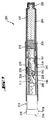
先ず、図1から3を参照すると、本発明のドラッグデリバリーデバイスが示されてある。
[Example 1]
Referring first to FIGS. 1-3, the drug delivery device of the present invention is shown.
ドラッグデリバリーデバイス(1)はカートリッジ保持部分(2)及び主(外部)ハウジング部分(3)を含む。カートリッジ保持部分(2)の基端部及び主ハウジング(3)の先端部は、当業者に公知の任意の適切な手段によって互いに固定される。図で示した実施態様において、カートリッジ保持部分(2)は、主ハウジング部分(3)の先端部内に固定されている。 The drug delivery device (1) comprises a cartridge holding part (2) and a main (external) housing part (3). The proximal end of the cartridge holding portion (2) and the distal end of the main housing (3) are secured together by any suitable means known to those skilled in the art. In the illustrated embodiment, the cartridge holding part (2) is fixed in the tip of the main housing part (3).
医薬品の多数の投与量を投与できるカートリッジ(4)を、カートリッジ保持部分(2)内に備える。ピストン(5)はカートリッジ(4)の基端部に保持される。 A cartridge (4) capable of administering a large number of doses of the pharmaceutical product is provided in the cartridge holding part (2). The piston (5) is held at the proximal end of the cartridge (4).
取りはずし可能なキャップ(22)はカートリッジ保持部分(2)の先端部の上に解放可能なように保持されている。取りはずし可能なキャップ(22)は、場合により一つ又はそれ以上の窓開口部を備えていてもよく、カートリッジ(4)内のピストン(5)の位置をそこから覗くことができる。 A removable cap (22) is releasably retained on the tip of the cartridge retaining portion (2). The removable cap (22) may optionally be provided with one or more window openings from which the position of the piston (5) in the cartridge (4) can be viewed.
図で示した実施態様におけるカートリッジ保持部分(2)の先端部には、薬剤をカートリッジ(4)から投与するのを可能ならしめるための、適切な針の組立て品を取付けるように設計された先端部ねじ領域(6)を備えている。 The tip of the cartridge holding part (2) in the illustrated embodiment is designed to be fitted with a suitable needle assembly to enable the drug to be dispensed from the cartridge (4) A partial screw region (6) is provided.
図で示した実施態様において、主ハウジング部分(3)は、内部ハウジング(7)を備えている。内部ハウジング(7)は、主ハウジング部分(3)に対して回転及び/又は軸方向の動きに抗して固定されている。内部ハウジング(7)は、内部ハウジング(7)の主軸に沿って延びるラック(8)を備えている。代替として、内部ハウジング(7)は主ハウジング部分(3)と一体的に形成されてもよい。また、内部ハウジング(7)は、複数のガイド・ラグ(図示せず)及び歯止め手段(図示せず)を備えている。歯止め手段は内部ハウジング(7)との一体化された部分であってもよく、又は図示されたような別の構成部品であってもよい。 In the illustrated embodiment, the main housing part (3) comprises an inner housing (7). The inner housing (7) is fixed against rotation and / or axial movement with respect to the main housing part (3). The inner housing (7) includes a rack (8) extending along the main axis of the inner housing (7). Alternatively, the inner housing (7) may be formed integrally with the main housing part (3). The inner housing (7) includes a plurality of guide lugs (not shown) and pawl means (not shown). The pawl means may be an integral part of the inner housing (7) or may be another component as shown.
主ハウジング(3)を通って延びるピストン棒(10)は、ピストン棒(10)の外面に沿って長手方向に延びる第一のセットのくぼみ(図示せず)を有する。第二のセットのくぼみ(11)は、ピストン棒(10)の内面に沿って長手方向に延びている。ピストン棒(10)の第一のセットのくぼみは、デバイスの設定中の基端部方向におけるピストン棒(10)の動きを防ぐために、内部ハウジング(7)の歯止め手段を通して延び、そしてその歯止め手段と係合する。ピストン棒(10)の先端部に位置している軸受面(12)は、ピストン(5)の基端部面に接するよう位置している。図で示した実施態様において、くぼみ(11)の第一のセット及び第二のセットの長手方向の間隔は本質的に等しい。 The piston rod (10) extending through the main housing (3) has a first set of indentations (not shown) extending longitudinally along the outer surface of the piston rod (10). The second set of indentations (11) extends longitudinally along the inner surface of the piston rod (10). A first set of indentations of the piston rod (10) extend through the pawl means of the inner housing (7) and prevent the pawl means to prevent movement of the piston rod (10) in the proximal direction during device setting. Engage with. The bearing surface (12) positioned at the distal end portion of the piston rod (10) is positioned so as to contact the proximal end surface of the piston (5). In the illustrated embodiment, the longitudinal spacing of the first and second sets of indentations (11) is essentially equal.
キャリア(28)及びギアホイール(27)から成り、キャリア(28)内で自由に回転するギア(13)は、ピストン棒(10)内のチャンネル中に位置している。キャリア(28)上に位置している歯止めアーム(29)は、ピストン棒(10)のくぼみ(11)の第二のセットと解放可能なように係合する。キャリア(28)の歯止めアーム(29)は、投与中に先端部方向にピストン棒(10)に力を伝動するように、そして設定中、基端部方向に、ギア(13)とピストン棒(10)の間で相対的に動くことを可能ならしめるように設計される。ギアホイール(27)の歯は内部ハウジング(7)のラック(8)の歯と恒久的に係合する。 A gear (13) consisting of a carrier (28) and a gear wheel (27), which rotates freely in the carrier (28), is located in a channel in the piston rod (10). A pawl arm (29) located on the carrier (28) releasably engages a second set of indentations (11) in the piston rod (10). The pawl arm (29) of the carrier (28) is adapted to transmit force to the piston rod (10) in the distal direction during administration and in the proximal direction during setting, to the gear (13) and piston rod ( Designed to allow relative movement between 10). The teeth of the gear wheel (27) are permanently engaged with the teeth of the rack (8) of the inner housing (7).
駆動部材(14)は、ピストン棒(10)の周りに延びる。駆動部材(14)は、ラック部分(15)及び作動部分(16)を含む。ラック部分(15)及び作動部分(16)は、その間での回転及び/又は軸方向運動を防ぐために互いに固定されている。代替として、駆動部材(14)は、一体化されたラック部分(15)及び作動部分(16)から成る単体の構成部品であってもよい。 The drive member (14) extends around the piston rod (10). The drive member (14) includes a rack portion (15) and an actuating portion (16). The rack part (15) and the actuating part (16) are secured to one another to prevent rotation and / or axial movement therebetween. Alternatively, the drive member (14) may be a single component consisting of an integrated rack portion (15) and actuating portion (16).
ラック部分(15)は、ラック部分(15)の主軸に沿って延びるラック(17)を備えている。ラック部分(15)のラック(17)の歯はギアホイール(27)の歯と恒久的に係合する。 The rack part (15) includes a rack (17) extending along the main axis of the rack part (15). The teeth of the rack (17) of the rack part (15) are permanently engaged with the teeth of the gear wheel (27).
駆動部材(14)は、内部ハウジング(7)のガイド・ラグ(図示せず)が中に位置している複数のガイドスロット(図示せず)を有する。これらのガイドスロットによって、ハウジング部分(3)に対する、駆動部材(14)の許容できる軸方向の動きの程度が規定される。図で示した実施態様において、ガイドスロットは、主ハウジング部分(3)に対する駆動部材(14)の回転運動も防ぐ。 The drive member (14) has a plurality of guide slots (not shown) in which guide lugs (not shown) of the inner housing (7) are located. These guide slots define the degree of allowable axial movement of the drive member (14) relative to the housing part (3). In the illustrated embodiment, the guide slot also prevents rotational movement of the drive member (14) relative to the main housing part (3).
駆動部材(14)の作動部分(16)は、複数のグリップ面(18)及び投与面(19)を有する。 The actuating part (16) of the drive member (14) has a plurality of grip surfaces (18) and a dispensing surface (19).
デバイスの操作の直観性を増すために、主ハウジング部分(3)は場合により窓開口部を備えていてもよく、それを通して駆動部材(14)に備えられたグラフィック状態インジケーターを覗くことができる。 In order to increase the intuitive operation of the device, the main housing part (3) may optionally be provided with a window opening through which a graphic status indicator provided on the drive member (14) can be viewed.
本発明のドラッグデリバリーデバイスの操作についてここで述べる。 The operation of the drug delivery device of the present invention will now be described.
投与量を設定するために、ユーザーは駆動部材(14)のグリップ面(18)を掴む。次いで、ユーザーは基端部方向に駆動部材(14)を引いて主ハウジング部分(3)から離し、それによってラック部分(15)を基端部方向に動かす。 To set the dosage, the user grips the grip surface (18) of the drive member (14). The user then pulls the drive member (14) in the proximal direction away from the main housing part (3), thereby moving the rack part (15) in the proximal direction.
ラック部分(15)の基端部側への動きの結果、ギア(13)のギアホイール(27)の歯がラック部分(15)のラック(17)の歯及び内部ハウジング(7)ラック(8)の歯と係合することによって、ギアホイール(27)が回転して基端部側に動き、そうしてギア(13)が基端部方向に動く。 As a result of the movement of the rack portion (15) toward the proximal end side, the teeth of the gear wheel (27) of the gear (13) become the teeth of the rack (17) of the rack portion (15) and the inner housing (7) rack (8). ), The gear wheel (27) rotates and moves toward the proximal end, and thus the gear (13) moves toward the proximal end.
内部ハウジング(7)の歯止め手段とピストン棒(10)上のくぼみの第一のセットとの相互作用は、ピストン棒(10)が基端部側に動くのを妨げる。駆動部材(14)がピストン棒(10)に対して基端部方向に移動するため、キャリア(28)の歯止めアーム(29)は、ピストン棒(10)のくぼみ(11)の第二のセットとの相互作用によって内側へ移される。 The interaction between the pawl means of the inner housing (7) and the first set of indentations on the piston rod (10) prevents the piston rod (10) from moving proximally. Since the drive member (14) moves in the proximal direction relative to the piston rod (10), the pawl arm (29) of the carrier (28) is a second set of indentations (11) in the piston rod (10). It is moved inward by the interaction.
駆動部材(14)の基端部側への移動は、ラック部分(15)のガイドスロットによって制限される。駆動部材(14)の移動の終わりに、図2に示される通り、キャリア(28)の歯止めアーム(29)は、ピストン棒(10)のくぼみ(11)の第二のセットの次に続くくぼみと係合する。ピストン棒(10)のくぼみ(11)の第二のセットと確実に係合するキャリア(28)の歯止めアーム(29)の動きによって、投与量が設定されていることを示すための、ユーザーへの聴覚的かつ触覚的なフィードバックが作出される。さらに、投与量投与に関する視覚的フィードバックを、場合により、駆動部材(14)に備えたグラフィック状態インジケーターによって示すことができ、それは主ハウジング部分(3)のオプションの窓開口部を通して覗くことができる。 The movement of the drive member (14) toward the proximal end side is limited by the guide slot of the rack portion (15). At the end of the movement of the drive member (14), as shown in FIG. 2, the pawl arm (29) of the carrier (28) is indented following the second set of indentations (11) in the piston rod (10). Engage with. To the user to indicate that the dose is set by the movement of the pawl arm (29) of the carrier (28) that securely engages the second set of indentations (11) in the piston rod (10) Auditory and tactile feedback is produced. In addition, visual feedback regarding dose administration can optionally be indicated by a graphic status indicator on the drive member (14), which can be viewed through an optional window opening in the main housing part (3).
投与量が設定されている場合、ユーザーは、駆動部材(14)の作動部分(16)の投与面(19)を押圧することによって、この投与量を投与することができる。この動きによって、駆動部材(14)及びラック部分(15)が、主ハウジング部分(3)に対して、先端部方向の軸方向に動かされる。ギア(13)のギアホイール(27)の歯がラック部分(15)のラック(17)の歯及び内部ハウジング(7)のラック(8)の歯と係合するため、ギア(13)のギアホイール(27)が回転されそして先端部方向に動かされ、そうしてそれが先端部方向において長手方向にギア(13)を動かすことになる。ギア(13)のキャリア(28)の歯止めアーム(29)がピストン棒(10)のくぼみ(11)の第二のセットと係合するため、ピストン棒(10)が内部ハウジング(7)に対して、遠位方向において縦に動かされることになる。 If a dose is set, the user can administer this dose by pressing the dosing surface (19) of the actuating part (16) of the drive member (14). By this movement, the drive member (14) and the rack part (15) are moved in the axial direction in the distal end direction with respect to the main housing part (3). Since the teeth of the gear wheel (27) of the gear (13) engage the teeth of the rack (17) of the rack portion (15) and the teeth of the rack (8) of the inner housing (7), the gear of the gear (13) The wheel (27) is rotated and moved in the tip direction, so that it moves the gear (13) in the longitudinal direction in the tip direction. The pawl arm (29) of the carrier (28) of the gear (13) engages with the second set of recesses (11) of the piston rod (10) so that the piston rod (10) is against the inner housing (7). Thus, it is moved vertically in the distal direction.
ピストン棒(10)の先端部軸方向の動きによって、ピストン棒(10)の軸受面(12)がカートリッジ(4)のピストン(5)に抗して耐えることになり、その結果、取付けられた針(図示せず)を通して薬剤の投与量が投与される。 The axial movement of the tip of the piston rod (10) causes the bearing surface (12) of the piston rod (10) to resist the piston (5) of the cartridge (4) and, as a result, mounted. A dose of drug is administered through a needle (not shown).
駆動部材(14)の先端部側への移動は、ラック部分(15)のガイドスロット(図示せず)によって制限される。投与量が投与されたことを示すための、聴覚的かつ触覚的なフィードバックが、内部ハウジング(7)の歯止め手段(図示せず)とピストン棒(10)のくぼみの第一のセット(図示せず)との相互作用によってもたらされる。さらに、投与量投与に関する視覚的フィードバックが、場合により駆動部材(14)に設けたグラフィック状態インジケーターによって示すことができ、それは主ハウジング部分(3)のオプションの窓開口部を通して覗くことができる。 The movement of the drive member (14) toward the tip end side is limited by a guide slot (not shown) of the rack portion (15). An audible and tactile feedback to indicate that a dose has been administered is a first set of pawl means (not shown) and a recess in the piston rod (10) (not shown) of the inner housing (7). )). Furthermore, visual feedback regarding dose administration can optionally be indicated by a graphic status indicator provided on the drive member (14), which can be viewed through an optional window opening in the main housing part (3).
必要に応じて所定の最大数の投与量まで更に投与量をデリバリーし得る。図3は、最大数の投与量がデリバリーされた条件における、本発明のドラッグデリバリーデバイスを示す。この条件において、ギア(13)従って基端部方向における駆動部材(14)の更なる軸方向の動きを防ぐため、キャリア(28)の基端面(32)は、ピストン棒(10)の内部先端面(33)に接する。 Further doses can be delivered as needed up to a predetermined maximum number of doses. FIG. 3 shows the drug delivery device of the present invention in conditions where the maximum number of doses has been delivered. Under this condition, the base end face (32) of the carrier (28) is the inner tip of the piston rod (10) to prevent further axial movement of the drive member (14) in the direction of the gear (13) and hence the base end. Touch the surface (33).
〔実施例2〕
図4から5を参照すると、本発明のドラッグデリバリーデバイスの代替実施態様を示されてある。
[Example 2]
Referring to FIGS. 4-5, an alternative embodiment of the drug delivery device of the present invention is shown.
ドラッグデリバリーデバイス(101)はカートリッジ保持部分(102)及び主(外部)ハウジング部分(103)を含む。カートリッジ保持部分(102)の基端部及び主ハウジング(103)の先端部は、当業者に公知の任意の適切な手段によって互いに固定される。図で示した実施態様において、カートリッジ保持部分(102)は、主ハウジング部分(103)の先端部内に固定されている。 The drug delivery device (101) includes a cartridge holding portion (102) and a main (external) housing portion (103). The proximal end of the cartridge holding portion (102) and the distal end of the main housing (103) are secured together by any suitable means known to those skilled in the art. In the illustrated embodiment, the cartridge retaining portion (102) is secured within the distal end of the main housing portion (103).
医薬品の多数の投与量を投与できるカートリッジ(104)を、カートリッジ保持部分(102)内に備える。ピストン(105)はカートリッジ(104)の基端部に保持される。 A cartridge (104) capable of administering multiple doses of a pharmaceutical product is provided in the cartridge holding portion (102). The piston (105) is held at the proximal end of the cartridge (104).
図で示した実施態様におけるカートリッジ保持部分(102)の先端部は、薬剤をカートリッジ(104)から投与するのを可能ならしめるための、適切な針の組立て品(図示せず)を取付けるように設計された先端ねじ領域(106)を備えている。 The tip of the cartridge retaining portion (102) in the illustrated embodiment is adapted to attach a suitable needle assembly (not shown) to allow medication to be dispensed from the cartridge (104). It has a designed tip screw area (106).
図で示した実施態様において、主ハウジング部分(103)は、内部ハウジング(107)を備えている。内部ハウジング(107)は主ハウジング部分(103)に対して回転及び/又は軸方向の動きに抗して固定されている。内部ハウジング(107)は、内部ハウジング(107)の主軸に沿って延びる、可撓性のラック(108)を備えている。代替として、内部ハウジング(107)は主ハウジング部分(103)と一体的に形成されてもよい。また、内部ハウジング(107)は、複数のガイドスロット(図示せず)及び歯止め手段(121)を備えている。 In the illustrated embodiment, the main housing part (103) comprises an inner housing (107). The inner housing (107) is fixed against rotation and / or axial movement with respect to the main housing part (103). The inner housing (107) includes a flexible rack (108) that extends along the main axis of the inner housing (107). Alternatively, the inner housing (107) may be integrally formed with the main housing part (103). The inner housing (107) includes a plurality of guide slots (not shown) and pawl means (121).
主ハウジング(103)を通って延びるピストン棒(110)は、ピストン棒(110)の表面に沿って長手方向に延びる一セットの歯(109)を有する。ピストン棒(110)の一セットの歯(109)は、デバイスの設定中基端部方向におけるピストン棒(110)の動きを防ぐために、内部ハウジング(107)の歯止め手段(121)を通して延び、そして歯止め手段と係合する。ピストン棒(110)の先端部に位置している軸受面(112)は、ピストン(105)の基端面に隣接するよう位置している。 The piston rod (110) extending through the main housing (103) has a set of teeth (109) extending longitudinally along the surface of the piston rod (110). A set of teeth (109) of the piston rod (110) extends through pawl means (121) of the inner housing (107) to prevent movement of the piston rod (110) in the proximal direction during device setting, and Engage with pawl means. The bearing surface (112) positioned at the distal end of the piston rod (110) is positioned adjacent to the proximal end surface of the piston (105).
ギア(113)は、ピストン棒(110)内のチャンネル中に位置している。ギア(113)の軸(128)は、ピストン棒(110)の一セットの歯(109)と解放可能なように係合する。一セットの歯(109)は、投与中先端部方向でピストン棒(110)に力を伝動するように、そして設定中、基端部方向に、ギア(113)とピストン棒(110)の間で相対的に動くことを可能ならしめるように設計されている。ギア(113)の歯は内部ハウジング(107)の可撓性のラック(108)の歯と恒久的に係合する。 The gear (113) is located in a channel in the piston rod (110). The shaft (128) of the gear (113) is releasably engaged with a set of teeth (109) of the piston rod (110). A set of teeth (109) transmit force to the piston rod (110) in the distal direction during administration and between the gear (113) and piston rod (110) in the proximal direction during setting. It is designed to make it possible to move relatively. The teeth of the gear (113) are permanently engaged with the teeth of the flexible rack (108) of the inner housing (107).
駆動部材(114)は、ピストン棒(110)の周りに延びる。駆動部材(114)は、ラック(115)及び作動部分(116)を含む。ラック(115)及び作動部分(116)は、その間での回転及び/又は軸方向の動きを防ぐために互いに固定されている。代替として、駆動部材(114)は、一体化されたラック(115)及び作動部分(116)から成る単体の構成部品であってもよい。 The drive member (114) extends around the piston rod (110). The drive member (114) includes a rack (115) and an actuating portion (116). The rack (115) and the actuating part (116) are secured together to prevent rotation and / or axial movement therebetween. Alternatively, the drive member (114) may be a single component consisting of an integrated rack (115) and actuating part (116).
ラック(115)の歯はギア(113)の歯と恒久的に係合する。 The teeth of the rack (115) are permanently engaged with the teeth of the gear (113).
駆動部材(114)は、内部ハウジング(107)のガイドスロット(図示せず)中に位置している複数のガイド・ラグ(図示せず)を有する。これによって、ハウジング部分(103)に対する、駆動部材(114)の許容できる軸方向の動きの程度が規定される。図で示した実施態様において、ガイドスロットは、主ハウジング部分(103)に対する駆動部材(114)の回転運動も防ぐ。 The drive member (114) has a plurality of guide lugs (not shown) located in guide slots (not shown) in the inner housing (107). This defines the degree of allowable axial movement of the drive member (114) relative to the housing part (103). In the illustrated embodiment, the guide slot also prevents rotational movement of the drive member (114) relative to the main housing portion (103).
駆動部材(114)の作動部分(116)は、グリップ面(118)及び投与面(119)を有する。 The actuation portion (116) of the drive member (114) has a gripping surface (118) and a dispensing surface (119).
デバイスの操作の直観性を増すために、主ハウジング部分(103)は場合により窓開口部を備えていてもよく、それを通して駆動部材(114)に備えるグラフィック状態インジケーターを覗くことができる。 To increase the intuitive operation of the device, the main housing part (103) may optionally be provided with a window opening through which the graphic status indicator provided on the drive member (114) can be viewed.
本発明のドラッグデリバリーデバイスの操作についてここで述べる。 The operation of the drug delivery device of the present invention will now be described.
投与量を設定するために、ユーザーは駆動部材(114)のグリップ面(118)を掴む。次いで、ユーザーは基端部方向に駆動部材(114)を引いて主ハウジング部分(103)から離し、それによってラック(115)を基端部方向に動かす。 To set the dose, the user grips the grip surface (118) of the drive member (114). The user then pulls the drive member (114) in the proximal direction away from the main housing portion (103), thereby moving the rack (115) in the proximal direction.
ラック(115)の基端部側への動きの結果、ギア(113)の歯がラック(115)の歯及び内部ハウジング(107)の可撓性のラック(108)の歯と係合することによって、ギア(113)が回転しそして基端部側に動く。 As a result of the proximal movement of the rack (115), the teeth of the gear (113) engage the teeth of the rack (115) and the flexible rack (108) of the inner housing (107). Causes the gear (113) to rotate and move proximally.
内部ハウジング(107)の歯止め手段(121)とピストン棒(110)上の一セットの歯(109)との相互作用は、ピストン棒(110)が基端部側に動くのを妨げる。駆動部材(114)がピストン棒(110)に対して基端部方向に移動するため、ギア(113)の軸(128)は、ピストン棒(110)の一セットの歯(109)との相互作用によって横に移され、そうして内部ハウジング(107)の可撓性ラック(108)を偏向させる。 The interaction between the pawl means (121) of the inner housing (107) and the set of teeth (109) on the piston rod (110) prevents the piston rod (110) from moving proximally. The drive member (114) moves in the proximal direction relative to the piston rod (110) so that the shaft (128) of the gear (113) interacts with the set of teeth (109) of the piston rod (110). It is moved sideways by action, thus deflecting the flexible rack (108) of the inner housing (107).
駆動部材(114)の基端部側への移動は、内部ハウジング(107)のガイドスロット(図示せず)によって制限される。駆動部材(114)の移動の終わりに、図5に示される通り、ギア(113)の軸(128)は、ピストン棒(110)の一セットの歯(109)の次に続く歯と係合する。内部ハウジング(107)の可撓性ラック(108)によって与えられる力の下で、ピストン棒(110)の一セットの歯(109)と確実に係合するギア(113)の軸(128)の動きによって、投与量が設定されていることを示すための、ユーザーへの聴覚的かつ触覚的なフィードバックが作出される。さらに、投与量設定に関する視覚的フィードバックが、場合により、駆動部材(114)に備えたグラフィック状態インジケーターによって示すことができ、それは主ハウジング部分(103)のオプションの窓開口部を通して覗くことができる。 Movement of the drive member (114) toward the proximal end side is limited by a guide slot (not shown) of the inner housing (107). At the end of the movement of the drive member (114), as shown in FIG. 5, the shaft (128) of the gear (113) engages the tooth following the set of teeth (109) of the piston rod (110). To do. Of the shaft (128) of the gear (113) that securely engages a set of teeth (109) of the piston rod (110) under the force provided by the flexible rack (108) of the inner housing (107). The movement creates an audible and tactile feedback to the user to indicate that the dose is being set. In addition, visual feedback regarding the dose setting can optionally be indicated by a graphic status indicator on the drive member (114), which can be viewed through an optional window opening in the main housing portion (103).
投与量が設定されている場合、ユーザーは、駆動部材(114)の作動部分(116)の投与面(119)を押圧することによって、この投与量を投与することができる。この動きによって、駆動部材(114)及びラック(115)が、主ハウジング部分(103)に対して、先端部方向の軸方向に動かされる。ギア(113)の歯がラック(115)の歯及び内部ハウジング(107)の可撓性のラック(108)の歯と係合するため、ギア(113)が回転されそして先端部方向に動かされる。ギア(113)の軸(128)はピストン棒(110)の一セットの歯(109)と係合し、それによって、ピストン棒(110)が内部ハウジング(107)に対して、先端部方向に長手方向に動かされることになる。 If a dose is set, the user can administer this dose by pressing the dosing surface (119) of the actuating portion (116) of the drive member (114). By this movement, the drive member (114) and the rack (115) are moved in the axial direction in the distal end direction with respect to the main housing portion (103). Because the teeth of the gear (113) engage the teeth of the rack (115) and the flexible rack (108) of the inner housing (107), the gear (113) is rotated and moved toward the tip. . The shaft (128) of the gear (113) engages a set of teeth (109) of the piston rod (110) so that the piston rod (110) is in the distal direction relative to the inner housing (107). It will be moved in the longitudinal direction.
ピストン棒(110)の先端部軸方向の動きによって、ピストン棒(110)の軸受面(112)がカートリッジ(104)のピストン(105)に抗して耐えることになり、その結果、取付けられた針(図示せず)を通して薬剤の投与量が投与される。 The axial movement of the tip of the piston rod (110) causes the bearing surface (112) of the piston rod (110) to resist the piston (105) of the cartridge (104) and is thus mounted. A dose of drug is administered through a needle (not shown).
駆動部材(114)の先端部側への移動は、内部ハウジング(107)のガイドスロット(図示せず)によって制限される。投与量が投与されていることを示すための、聴覚的かつ触覚的なフィードバックが、内部ハウジング(107)の歯止め手段(121)とピストン棒(110)の一セットの歯(109)との相互作用によって与えられる。さらに、投与量投与に関する視覚的フィードバックが、場合により駆動部材(114)上に備えたグラフィック状態インジケーターによって示すことができ、それは主ハウジング部分(103)のオプションの窓開口部を通して覗くことができる。 The movement of the driving member (114) toward the distal end side is limited by a guide slot (not shown) of the inner housing (107). An audible and tactile feedback to indicate that a dose is being administered is provided between the pawl means (121) of the inner housing (107) and the set of teeth (109) of the piston rod (110). Given by action. Furthermore, visual feedback regarding dose administration can optionally be indicated by a graphical status indicator provided on the drive member (114), which can be viewed through an optional window opening in the main housing portion (103).
必要に応じて所定の最大数の投与量まで、更に投与量をデリバリーし得る。 Additional doses can be delivered as needed up to a predetermined maximum number of doses.
〔実施例3〕
図6から7を参照すると、本発明のドラッグデリバリーデバイスの更なる代替実施態様が示されてある。
Example 3
Referring to FIGS. 6-7, a further alternative embodiment of the drug delivery device of the present invention is shown.
ドラッグデリバリーデバイス(201)はカートリッジ保持部分(202)及び主(外部)ハウジング部分(203)を含む。カートリッジ保持部分(202)の基端部及び主ハウジング(203)の先端部は、当業者に公知の任意の適切な手段によって互いに固定される。図で示した実施態様において、カートリッジ保持部分(202)は、主ハウジング部分(203)の先端部内に固定されている。 The drug delivery device (201) includes a cartridge holding portion (202) and a main (external) housing portion (203). The proximal end of the cartridge retaining portion (202) and the distal end of the main housing (203) are secured together by any suitable means known to those skilled in the art. In the illustrated embodiment, the cartridge retaining portion (202) is secured within the distal end of the main housing portion (203).
医薬品の多数の投与量を投与できるカートリッジ(204)を、カートリッジ保持部分(202)内に備える。ピストン(205)はカートリッジ(204)の基端部に保持される。 A cartridge (204) capable of administering multiple doses of a pharmaceutical product is provided in the cartridge holding portion (202). The piston (205) is held at the proximal end of the cartridge (204).
図で示した実施態様におけるカートリッジ保持部分(202)の先端部には、薬剤をカートリッジ(204)から投与するのを可能ならしめるための、適切な針の組立て品を取付けるために設計された先端部ねじ領域(206)を備えている。 The tip of the cartridge-holding portion (202) in the illustrated embodiment is designed to attach a suitable needle assembly to allow medication to be dispensed from the cartridge (204) A partial screw region (206) is provided.
図で示した実施態様において、主ハウジング部分(203)には、内部ハウジング(207)を備えている。内部ハウジング(207)は主ハウジング部分(203)に対して回転及び/又は軸方向の動きに抗して固定されている。内部ハウジング(207)は、プーリ(240)を取付けるための固定点(208)を備えている。代替として、内部ハウジング(207)は主ハウジング部分(203)と一体的に形成されてもよい。また、内部ハウジング(207)は、ガイドスロット(図示せず)及び歯止め手段(図示せず)を備えている。 In the illustrated embodiment, the main housing part (203) is provided with an internal housing (207). The inner housing (207) is fixed against rotation and / or axial movement with respect to the main housing part (203). The inner housing (207) includes a fixed point (208) for attaching a pulley (240). Alternatively, the inner housing (207) may be integrally formed with the main housing part (203). The inner housing (207) includes a guide slot (not shown) and pawl means (not shown).
主ハウジング(203)を通って延びるピストン棒(210)は、ピストン棒(210)の表面に沿って長手方向に延びる第一のセットの歯(209)及び第二のセットの歯(211)を有する。ピストン棒(210)の第二のセットの歯(211)は、デバイスの設定中基端部方向のピストン棒(210)の動きを防ぐために、内部ハウジング(207)の歯止め手段(図示せず)を通して延び、そして歯止め手段と係合する。ピストン棒(210)の先端部に位置している軸受面(212)は、ピストン(205)の基端面に隣接するよう位置している。 The piston rod (210) extending through the main housing (203) has a first set of teeth (209) and a second set of teeth (211) extending longitudinally along the surface of the piston rod (210). Have. The second set of teeth (211) of the piston rod (210) are pawl means (not shown) in the inner housing (207) to prevent movement of the piston rod (210) in the proximal direction during device setting. Extends through and engages the pawl means. The bearing surface (212) positioned at the distal end of the piston rod (210) is positioned adjacent to the proximal end surface of the piston (205).
ベルト(241)及び歯車(242)を含むプーリ(240)は、ピストン棒(210)内のチャンネル内に位置している。歯車(242)の軸(228)は、ピストン棒(210)の歯(209)の第一のセットと解放可能なように係合する。歯(209)の第一のセットは、投与中先端部方向においてピストン棒(210)に力を伝動し得るよう、そして設定中、基端部方向に、プーリ(240)とピストン棒(210)の間で相対的に動くことを可能ならしめるように設計される。歯車(242)の歯は、プーリ(240)のベルト(241)の歯と恒久的に係合する。 A pulley (240) including a belt (241) and a gear (242) is located in a channel in the piston rod (210). The shaft (228) of the gear (242) is releasably engaged with the first set of teeth (209) of the piston rod (210). The first set of teeth (209) can transmit force to the piston rod (210) in the distal direction during administration, and in the proximal direction during setting, the pulley (240) and the piston rod (210). Designed to make it possible to move relatively between. The teeth of the gear (242) are permanently engaged with the teeth of the belt (241) of the pulley (240).
駆動部材(214)は、ピストン棒(210)の周りに延びている。駆動部材(214)は、固定点(215)及び作動部分(216)を含む。固定点(215)及び作動部分(216)は、その間での回転及び/又は軸方向の動きを防ぐために互いに固定されている。代替として、駆動部材(214)は、一体化された固定点(215)及び作動部分(216)から成る単体の構成部品であってもよい。 The drive member (214) extends around the piston rod (210). The drive member (214) includes a fixed point (215) and an actuating portion (216). The fixed point (215) and the working part (216) are fixed to each other to prevent rotation and / or axial movement therebetween. Alternatively, the drive member (214) may be a unitary component consisting of an integrated fixation point (215) and actuation portion (216).
プーリ(240)のベルト(241)は、固定点(215)で駆動部材(214)に取付けられている。 The belt (241) of the pulley (240) is attached to the drive member (214) at a fixed point (215).
駆動部材(214)は、内部ハウジング(207)のガイドスロット(図示せず)中に位置している複数のガイド・ラグ(図示せず)を有する。これによって、ハウジング部分(203)に対する、駆動部材(214)の許容できる軸方向の動きの程度が規定される。図で示した実施態様において、ガイドスロットは、主ハウジング部分(203)に対する駆動部材(214)の回転運動も防ぐ。 The drive member (214) has a plurality of guide lugs (not shown) located in guide slots (not shown) in the inner housing (207). This defines the degree of allowable axial movement of the drive member (214) relative to the housing part (203). In the illustrated embodiment, the guide slot also prevents rotational movement of the drive member (214) relative to the main housing portion (203).
駆動部材(214)の作動部分(216)は、グリップ面(218)及び投与面(219)を有する。 The actuation portion (216) of the drive member (214) has a gripping surface (218) and a dispensing surface (219).
デバイスの操作の直観性を増すために、主ハウジング部分(203)はオプションの窓開口部を備えていてもよく、それを通して駆動部材(214)に備えたオプションのグラフィック状態インジケーターを、覗くことができる。 To increase the intuitive operation of the device, the main housing part (203) may be provided with an optional window opening through which an optional graphic status indicator provided on the drive member (214) can be viewed. it can.
本発明のドラッグデリバリーデバイスの操作についてここで述べる。 The operation of the drug delivery device of the present invention will now be described.
投与量を設定するために、ユーザーは駆動部材(214)のグリップ面(218)を掴む。次いで、ユーザーは基端部方向に駆動部材(214)を引いて主ハウジング部分(203)から離し、そのことによってラック(215)を基端部方向に動かす。 To set the dose, the user grips the grip surface (218) of the drive member (214). The user then pulls the drive member (214) in the proximal direction away from the main housing portion (203), thereby moving the rack (215) in the proximal direction.
駆動部材(214)の基端部側への動きの結果、プーリ(240)のベルト(241)を、駆動部材(214)の固定点(215)及び内部ハウジング(207)の固定点(208)の両方に取付けることによって、プーリ(240)の歯車(242)が回転しそして基端部側に動く。 As a result of the movement of the driving member (214) toward the proximal end side, the belt (241) of the pulley (240) is moved to the fixing point (215) of the driving member (214) and the fixing point (208) of the inner housing (207). By attaching to both, the gear (242) of the pulley (240) rotates and moves proximally.
内部ハウジング(207)の歯止め手段(図示せず)とピストン棒(210)の第二のセットの歯(211)との相互作用は、ピストン棒(210)が基端部側に動くのを妨げる。駆動部材(214)がピストン棒(210)に対して基端部方向に移動するため、ホイール(242)の軸(228)は、ピストン棒(210)の第一のセットの歯(209)との相互作用によって横に移され、そうしてプーリ(240)のベルト(241)を偏向させる。 Interaction between the pawl means (not shown) of the inner housing (207) and the second set of teeth (211) of the piston rod (210) prevents the piston rod (210) from moving proximally. . As the drive member (214) moves proximally relative to the piston rod (210), the shaft (228) of the wheel (242) is in contact with the first set of teeth (209) of the piston rod (210). Of the pulley (240), thereby deflecting the belt (241).
駆動部材(214)の基端部側への移動は、内部ハウジング(207)のガイドスロット(図示せず)によって制限される。駆動部材(214)の移動の終わりに、図7に示される通り、歯車(242)の軸(228)は、ピストン棒(210)の第一のセットの歯(209)の次に続く歯と係合する。プーリ(240)のベルト(241)によって与えられる力の下で、ピストン棒(210)の一セットの歯(209)と確実に係合する歯車(242)の軸(228)の動きによって、投与量が設定されていることを示すための、ユーザーへの聴覚的かつ触覚的なフィードバックが作出される。また、投与量設定に関する視覚的フィードバックが、場合により、駆動部材(214)上に備えたグラフィック状態インジケーターによって示すことができ、それは主ハウジング部分(203)のオプションの窓開口部を通して覗くことができる。 Movement of the drive member (214) toward the proximal end side is limited by a guide slot (not shown) of the inner housing (207). At the end of the movement of the drive member (214), as shown in FIG. 7, the shaft (228) of the gear (242) is connected to the teeth following the first set of teeth (209) of the piston rod (210). Engage. The administration of the shaft (228) of the gear (242) that positively engages the set of teeth (209) of the piston rod (210) under the force provided by the belt (241) of the pulley (240). Auditory and tactile feedback to the user is created to indicate that the quantity is set. Also, visual feedback regarding dose setting can optionally be indicated by a graphic status indicator provided on the drive member (214), which can be viewed through an optional window opening in the main housing portion (203). .
投与量が設定されている場合、ユーザーは、駆動部材(214)の作動部分(216)の投与面(219)を押圧することによって、この投与量を投与することができる。この動きによって、駆動部材(214)及び固定点(215)が、主ハウジング部分(203)に対して、先端部方向の軸方向に動かされる。プーリ(240)のベルト(241)が駆動部材(214)の固定点(215)に取り付けられ、そしてプーリ(240)のベルト(241)が内部ハウジング(207)の固定点(208)にも取り付けられているため、ベルト(241)の歯がホイール(242)の歯と係合することによって、プーリ(240)のホイール(242)が回転されそして先端部方向に動かされる。プーリ(240)の歯車(242)の軸(228)はピストン棒(210)の第一のセットの歯(209)と係合し、それによって、ピストン棒(210)が内部ハウジング(207)に対して、先端部方向に軸方向に動かされることになる。 If a dose is set, the user can administer this dose by pressing the dosing surface (219) of the actuating portion (216) of the drive member (214). By this movement, the driving member (214) and the fixing point (215) are moved in the axial direction toward the distal end with respect to the main housing portion (203). The belt (241) of the pulley (240) is attached to the fixing point (215) of the drive member (214), and the belt (241) of the pulley (240) is also attached to the fixing point (208) of the inner housing (207). Thus, the engagement of the teeth of the belt (241) with the teeth of the wheel (242) causes the wheel (242) of the pulley (240) to be rotated and moved toward the tip. The shaft (228) of the gear (242) of the pulley (240) engages the first set of teeth (209) of the piston rod (210), thereby causing the piston rod (210) to engage the inner housing (207). On the other hand, it is moved in the axial direction toward the tip.
ピストン棒(210)の先端部軸方向の動きによって、ピストン棒(210)の軸受面(212)がカートリッジ(204)のピストン(205)に抗して耐えることになり、その結果、取付けられた針(図示せず)を通して薬剤の投与量が投与される。 The axial movement of the tip of the piston rod (210) causes the bearing surface (212) of the piston rod (210) to resist the piston (205) of the cartridge (204) and is thus mounted. A dose of drug is administered through a needle (not shown).
駆動部材(214)の先端部側への移動は、内部ハウジング(207)のガイドスロット(図示せず)によって制限される。投与量が投与されていることを示すための、聴覚的かつ触覚的なフィードバックが、内部ハウジング(207)の歯止め手段(図示せず)とピストン棒(210)の第二のセットの歯(211)との相互作用によって与えられる。また、投与量投与に関する視覚的フィードバックが、場合により駆動部材(214)に備えたグラフィック状態インジケーターによって示すことができ、それは主ハウジング部分(203)のオプションの窓開口部を通して覗くことができる。 The movement of the driving member (214) toward the distal end side is limited by a guide slot (not shown) of the inner housing (207). An audible and tactile feedback to indicate that a dose is being administered is provided by the pawl means (not shown) of the inner housing (207) and the second set of teeth (211) of the piston rod (210). ). Also, visual feedback regarding dose administration can optionally be indicated by a graphical status indicator on the drive member (214), which can be viewed through an optional window opening in the main housing portion (203).
必要に応じて所定の最大数の投与量まで更に投与量をデリバリーし得る。 Further doses can be delivered as needed up to a predetermined maximum number of doses.
〔実施例4〕
図8から10を参照すると、本発明のドラッグデリバリーデバイスの更なる代替実施態様が示されてある。
Example 4
Referring to FIGS. 8-10, a further alternative embodiment of the drug delivery device of the present invention is shown.
ドラッグデリバリーデバイス(301)はカートリッジ保持部分(302)及び主(外部)ハウジング部分(303)を含む。カートリッジ保持部分(302)の基端部及び主ハウジング(303)の先端部は、当業者に公知の任意の適切な手段によって互いに固定される。図で示した実施態様において、カートリッジ保持部分(302)は、主ハウジング部分(303)の先端部内に固定されている。 The drug delivery device (301) includes a cartridge holding portion (302) and a main (external) housing portion (303). The proximal end of the cartridge holding portion (302) and the distal end of the main housing (303) are secured together by any suitable means known to those skilled in the art. In the illustrated embodiment, the cartridge retaining portion (302) is secured within the distal end of the main housing portion (303).
医薬品の多数の投与量を投与できるカートリッジ(304)を、カートリッジ保持部分(302)内に備える。ピストン(305)はカートリッジ(304)の基端部に保持される。 A cartridge (304) capable of administering multiple doses of a pharmaceutical product is provided in the cartridge holding portion (302). The piston (305) is held at the proximal end of the cartridge (304).
図で示した実施態様におけるカートリッジ保持部分(302)の先端部は、薬剤をカートリッジ(304)から投与するのを可能ならしめるための、適切な針の組立て品(図示せず)を取付けるために設計された先端部ねじ領域(306)を備えている。 The tip of the cartridge holding portion (302) in the illustrated embodiment is for attaching a suitable needle assembly (not shown) to enable the drug to be dispensed from the cartridge (304). Designed tip screw area (306).
図で示した実施態様において、主ハウジング部分(303)は、内部ハウジング(307)を備えている。内部ハウジング(307)は主ハウジング部分(303)に対して回転及び/又は軸方向の動きに抗して固定されている。内部ハウジング(307)は、レバー(340)を取付けるための支点(308)を備えている。代替として、内部ハウジング(307)は主ハウジング部分(303)と一体的に形成されてもよい。また、内部ハウジング(307)は、ガイドスロット(図示せず)及び歯止め手段(345)を備えている。 In the illustrated embodiment, the main housing part (303) comprises an inner housing (307). The inner housing (307) is fixed against rotational and / or axial movement with respect to the main housing part (303). The inner housing (307) includes a fulcrum (308) for mounting the lever (340). Alternatively, the inner housing (307) may be integrally formed with the main housing portion (303). The inner housing (307) includes a guide slot (not shown) and pawl means (345).
主ハウジング(303)を通って延びるピストン棒(310)は、ピストン棒(310)の表面に沿って長手方向に延びる第一のセットのくぼみ(309及び309’)及び第二のセットのくぼみ(311及び311’)を有する。ピストン棒(310)の第二のセットのくぼみ(311及び311’)は、デバイスの設定中基端方向のピストン棒(310)の動きを防ぐために、内部ハウジング(307)の歯止め手段(345)を通して延び、そしてそれと係合する。ピストン棒(310)の先端部に位置している軸受面(312)は、ピストン(305)の基端面に隣接するよう位置している。 A piston rod (310) extending through the main housing (303) is provided with a first set of indentations (309 and 309 ′) and a second set of indentations (309) extending longitudinally along the surface of the piston rod (310). 311 and 311 ′). The second set of indentations (311 and 311 ′) of the piston rod (310) is a pawl means (345) in the inner housing (307) to prevent movement of the piston rod (310) in the proximal direction during device setting. Extends through and engages. The bearing surface (312) located at the distal end of the piston rod (310) is located adjacent to the proximal end surface of the piston (305).
複数の出張り(341)並びに第一ピボット(342)及び第二ピボット(343)を含むレバー(340)は、ピストン棒(310)内のチャンネル内に位置している。レバー(340)の出張り(341)は、ピストン棒(310)のくぼみ(309及び309’)の第一のセットと解放可能なように係合する。くぼみ(309及び309’)の第一のセットは、投与中先端部方向にピストン棒(310)に力を伝動できるよう、そして設定中、基端部方向に、レバー(340)とピストン棒(310)の間で相対的に動くことを可能ならしめるように設計される。レバー(340)の第一ピボット(342)は、内部ハウジング(307)の支点(308)に、その間での旋回運動(pivotable movement)のために取付けられる。 A lever (340) including a plurality of ledges (341) and a first pivot (342) and a second pivot (343) is located in a channel in the piston rod (310). The ledge (341) of the lever (340) releasably engages the first set of indentations (309 and 309 ') of the piston rod (310). The first set of indentations (309 and 309 ′) is capable of transmitting force to the piston rod (310) in the distal direction during administration and, in the setting, in the proximal direction, the lever (340) and piston rod ( 310) is designed to be able to move relatively between. The first pivot (342) of the lever (340) is attached to the fulcrum (308) of the inner housing (307) for pivotable movement therebetween.
駆動部材(314)は、ピストン棒(310)の周りに延びている。駆動部材(314)は、スロット(315)及び作動部分(316)を含む。スロット(315)及び作動部分(316)は、その間での回転及び/又は軸方向の動きを防ぐために互いに固定されている。代替として、駆動部材(314)は、一体化されたスロット(315)及び作動部分(316)から成る単体の構成部品であってもよい。 The drive member (314) extends around the piston rod (310). The drive member (314) includes a slot (315) and an actuating portion (316). Slot (315) and actuating part (316) are secured together to prevent rotation and / or axial movement therebetween. Alternatively, the drive member (314) may be a single component consisting of an integrated slot (315) and actuating portion (316).
レバー(340)の第二ピボット(343)は駆動部材(314)のスロット(315)内に位置している。駆動部材(314)のスロット(315)は、駆動部材(314)に対するレバー(340)の第二ピボット(343)の横の動きを可能ならしめるが、長手方向の動きをさせないように設計される。 The second pivot (343) of the lever (340) is located in the slot (315) of the drive member (314). The slot (315) of the drive member (314) is designed to allow lateral movement of the second pivot (343) of the lever (340) relative to the drive member (314), but not longitudinal movement. .
駆動部材(314)は、内部ハウジング(307)のガイドスロット(図示せず)中に位置しているガイド・ラグ(346)を有する。これによって、ハウジング部分(303)に対する駆動部材(314)の許容できる軸方向の動きの程度が規定される。図で示した実施態様において、ガイドスロットは、主ハウジング部分(303)に対する駆動部材(314)の回転運動も防ぐ。 The drive member (314) has a guide lug (346) located in a guide slot (not shown) in the inner housing (307). This defines the degree of allowable axial movement of the drive member (314) relative to the housing portion (303). In the illustrated embodiment, the guide slot also prevents rotational movement of the drive member (314) relative to the main housing portion (303).
駆動部材(314)の作動部分(316)は、グリップ面(318)及び投与面(319)を有する。 The actuation portion (316) of the drive member (314) has a gripping surface (318) and a dispensing surface (319).
デバイスの操作の直観性を増すために、主ハウジング部分(303)には場合により窓開口部を備えていてもよく、それを通して駆動部材(314)に備えるグラフィック状態インジケーターを、覗くことができる。 In order to increase the intuitive operation of the device, the main housing part (303) may optionally be provided with a window opening through which the graphic status indicator provided on the drive member (314) can be viewed.
本発明のドラッグデリバリーデバイスの操作についてここで述べる。 The operation of the drug delivery device of the present invention will now be described.
投与量を設定するために、ユーザーは駆動部材(314)のグリップ面(318)を掴む。次いで、ユーザーは基端部方向に駆動部材(314)を引いて主ハウジング部分(303)から離し、そのことによって固定点(315)を基端部方向に動かす。 To set the dose, the user grasps the grip surface (318) of the drive member (314). The user then pulls the drive member (314) in the proximal direction away from the main housing portion (303), thereby moving the fixation point (315) in the proximal direction.
駆動部材(314)の基端部側への動きの結果、レバー(340)の第二ピボット(343)を駆動部材(314)のスロット(315)内に位置させることによって、レバー(340)が内部ハウジング(307)の支点(308)の周りで回転することになる。 Positioning the second pivot (343) of the lever (340) within the slot (315) of the drive member (314) as a result of the movement of the drive member (314) toward the proximal end causes the lever (340) to move. It will rotate around the fulcrum (308) of the inner housing (307).
内部ハウジング(307)の歯止め手段(345)とピストン棒(310)の第二のセットのくぼみ(311及び311’)との相互作用は、ピストン棒(310)が基端部側に動くのを妨げる。駆動部材(314)がピストン棒(310)に対して基端部方向に移動するため、レバー(340)の出張り(341)は、ピストン棒(310)の第一のセットのくぼみ(309及び309’)との相互作用によって横に移される。 The interaction between the pawl means (345) of the inner housing (307) and the second set of indentations (311 and 311 ′) of the piston rod (310) causes the piston rod (310) to move proximally. Hinder. Because the drive member (314) moves proximally relative to the piston rod (310), the ledge (341) of the lever (340) causes the first set of indentations (309 and 309) of the piston rod (310). 309 ′) is moved sideways.
駆動部材(314)の基端部側への移動は、内部ハウジング(307)のガイドスロット(図示せず)によって制限される。駆動部材(314)の移動の終わりに、図10に示される通り、レバー(340)の出張り(341)は、ピストン棒(310)の第一のセットのくぼみ(309及び309’)の次に続くくぼみと係合する。レバー(340)の横の偏向によって与えられる力の下で、ピストン棒(310)の第一のセットのくぼみ(309及び309’)と確実に係合するレバー(340)の出張り(341)の動きによって、投与量が設定されていることを示すための、ユーザーへの聴覚的かつ触覚的なフィードバックが作出される。さらに、投与量設定に関する視覚的フィードバックが、場合により、駆動部材(314)に備えたグラフィック状態インジケーターによって示すことができ、それは主ハウジング部分(303)のオプションの窓開口部を通して覗くことができる。 Movement of the drive member (314) toward the proximal end side is limited by a guide slot (not shown) of the inner housing (307). At the end of the movement of the drive member (314), as shown in FIG. 10, the protrusion (341) of the lever (340) is next to the indentations (309 and 309 ′) of the first set of piston rods (310). Engage with the recess following. Protrusion (341) of lever (340) that positively engages indentations (309 and 309 ') of the first set of piston rod (310) under the force provided by lateral deflection of lever (340) Movement creates an audible and tactile feedback to the user to indicate that the dose has been set. In addition, visual feedback regarding the dose setting can optionally be indicated by a graphic status indicator on the drive member (314), which can be viewed through an optional window opening in the main housing portion (303).
投与量が設定されている場合、ユーザーは、駆動部材(314)の作動部分(316)の投与面(319)を押圧することによって、この投与量を投与することができる。この動きによって、駆動部材(314)及びスロット(315)が、主ハウジング部分(303)に対して、先端部方向の軸方向に動かされる。レバー(340)の第二ピボット(343)を駆動部材(314)のスロット(315)内に位置させるため、レバー(340)が内部ハウジング(307)の支点(308)の周りで先端部方向に回転される。レバー(340)の出張り(341)はピストン棒(310)の第一のセットのくぼみ(309及び309’)と係合し、それによって、ピストン棒(310)が内部ハウジング(307)に対して、先端部方向に軸方向に動かされることになる。 If a dose is set, the user can administer this dose by pressing the dosing surface (319) of the actuation portion (316) of the drive member (314). This movement causes the drive member (314) and the slot (315) to move axially in the distal direction relative to the main housing portion (303). In order to position the second pivot (343) of the lever (340) within the slot (315) of the drive member (314), the lever (340) is directed toward the distal end around the fulcrum (308) of the inner housing (307). It is rotated. The ledge (341) of the lever (340) engages the first set of indentations (309 and 309 ') of the piston rod (310) so that the piston rod (310) is against the inner housing (307). Thus, it is moved in the axial direction toward the tip.
ピストン棒(310)の先端部軸方向の動きによって、ピストン棒(310)の軸受面(312)がカートリッジ(304)のピストン(305)に抗して耐えることになり、その結果、取付けられた針(図示せず)を通して薬剤の投与量が投与される。 The axial movement of the tip of the piston rod (310) causes the bearing surface (312) of the piston rod (310) to resist the piston (305) of the cartridge (304) and is thus mounted. A dose of drug is administered through a needle (not shown).
駆動部材(314)の先端部側への移動は、内部ハウジング(307)のガイドスロット(図示せず)によって制限される。投与量が投与されていることを示すための、聴覚的かつ触覚的なフィードバックが、内部ハウジング(307)の歯止め手段(345)とピストン棒(310)の第二のセットのくぼみ(311及び311’)との相互作用によって与えられる。また、投与量投与に関する視覚的フィードバックが、場合により駆動部材(314)に備えるグラフィック状態インジケーターによって示すことができ、それは主ハウジング部分(303)のオプションの窓開口部を通して覗くことができる。 The movement of the drive member (314) toward the distal end side is limited by a guide slot (not shown) of the inner housing (307). An audible and tactile feedback to indicate that a dose is being administered is provided in the second set of indentations (311 and 311) of the pawl means (345) of the inner housing (307) and the piston rod (310). Given by interaction with '). Also, visual feedback regarding dose administration can be indicated by a graphic status indicator, optionally provided on the drive member (314), which can be viewed through an optional window opening in the main housing portion (303).
必要に応じて所定の最大数の投与量まで更に投与量をデリバリーし得る。 Further doses can be delivered as needed up to a predetermined maximum number of doses.
〔実施例5〕
図11から12を参照すると、本発明のドラッグデリバリーデバイスの更なる代替実施態様が示されてある。
Example 5
Referring to FIGS. 11-12, a further alternative embodiment of the drug delivery device of the present invention is shown.
ドラッグデリバリーデバイス(401)はカートリッジ保持部分(402)及び主(外部)ハウジング部分(403)を含む。カートリッジ保持部分(402)の基端部及び主ハウジング(403)の先端部は、当業者に公知の任意の適切な手段によって互いに固定される。図で示した実施態様において、カートリッジ保持部分(402)は、主ハウジング部分(403)の先端部内に固定されている。 The drug delivery device (401) includes a cartridge holding portion (402) and a main (external) housing portion (403). The proximal end of the cartridge holding portion (402) and the distal end of the main housing (403) are secured together by any suitable means known to those skilled in the art. In the illustrated embodiment, the cartridge retaining portion (402) is secured within the distal end of the main housing portion (403).
医薬品の多数の投与量を投与できるカートリッジ(404)を、カートリッジ保持部分(402)内に備える。ピストン(405)はカートリッジ(404)の基端部に保持されている。 A cartridge (404) capable of administering multiple doses of pharmaceuticals is provided in the cartridge holding portion (402). The piston (405) is held at the proximal end of the cartridge (404).
取りはずし可能なキャップ(422)はカートリッジ保持部分(402)の先端部上に解放可能なように保持されている。取りはずし可能なキャップ(422)には、場合により、一つ又はそれ以上の窓開口部を備えており、そこからカートリッジ(404)内のピストン(405)の位置を覗くことができる。 A removable cap (422) is releasably retained on the tip of the cartridge retaining portion (402). The removable cap (422) is optionally provided with one or more window openings from which the position of the piston (405) within the cartridge (404) can be viewed.
図で示した実施態様におけるカートリッジ保持部分(402)の先端部には、薬剤をカートリッジ(404)から投与するのを可能ならしめるための、適切な針の組立て品(図示せず)を取付けるために設計された先端ねじ領域(406)を備えている。 To attach the appropriate needle assembly (not shown) to the distal end of the cartridge-holding portion (402) in the illustrated embodiment to allow medication to be dispensed from the cartridge (404). The tip screw region (406) designed in the above.
図で示した実施態様において、主ハウジング部分(403)は、内部ハウジング(407)を備えている。内部ハウジング(407)は、主ハウジング部分(403)に対して回転及び/又は軸方向の動きに抗して固定されている。内部ハウジング(407)は支点(408)を備えている。代替として、内部ハウジング(407)は主ハウジング部分(403)と一体的に形成されてもよい。また、内部ハウジング(407)は、複数のガイド・ラグ(図示せず)及び歯止め手段(図示せず)を備えている。歯止め手段は内部ハウジング(407)と一体化された部分であってもよく、又は図で示されたように別の構成部品であってもよい。 In the illustrated embodiment, the main housing part (403) comprises an inner housing (407). The inner housing (407) is fixed against rotation and / or axial movement with respect to the main housing part (403). The inner housing (407) is provided with a fulcrum (408). Alternatively, the inner housing (407) may be integrally formed with the main housing portion (403). The inner housing (407) includes a plurality of guide lugs (not shown) and pawl means (not shown). The pawl means may be an integral part of the inner housing (407) or may be a separate component as shown in the figure.
主ハウジング(403)を通って延びるピストン棒(410)は、ピストン棒(410)の外面に沿って長手方向に延びる第一のセットのくぼみ(図示せず)を有する。第二のセットのくぼみ(411)は、ピストン棒(410)の内部表面に沿って長手方向に伸びる。ピストン棒(410)の第一のセットのくぼみは、デバイスの設定中基端部方向のピストン棒(410)の動きを防ぐために、内部ハウジング(407)の歯止め手段を通して延び、そしてそれと係合する。ピストン棒(410)の先端部に位置している軸受面(412)は、ピストン(405)の基端面に隣接するよう位置している。図で示した実施態様において、第一のセットのくぼみと第二のセットのくぼみ(411)の長手方向の空隙は本質的に等しい。 The piston rod (410) extending through the main housing (403) has a first set of indentations (not shown) extending longitudinally along the outer surface of the piston rod (410). The second set of indentations (411) extends longitudinally along the internal surface of the piston rod (410). A first set of indentations in the piston rod (410) extend through and engage with pawl means in the inner housing (407) to prevent movement of the piston rod (410) in the proximal direction during device setting. . The bearing surface (412) positioned at the distal end of the piston rod (410) is positioned adjacent to the proximal end surface of the piston (405). In the illustrated embodiment, the longitudinal voids of the first set of indentations and the second set of indentations (411) are essentially equal.
キャリア(428)及びレバー(427)から成り、キャリア(428)内で自由に回転するレバー組み立て品(413)は、ピストン棒(410)内のチャンネル中に位置している。レバー(427)は第一ピボット(442)及び第二ピボット(443)を備えている。キャリア(428)上に位置している歯止めアーム(429)はピストン棒(410)のくぼみ(411)の第二のセットと解放可能なように係合する。キャリア(428)の歯止めアーム(429)は、投与中先端部方向にピストン棒(410)に力を伝動できるよう、そして設定中、基端部方向に、レバー組立て品(413)とピストン棒(410)の間で相対的に動くことを可能ならしめるように設計される。レバー(440)の第一ピボット(442)は、内部ハウジング(407)の支点(408)に、その間での旋回運動のために取付けられる。 A lever assembly (413), consisting of a carrier (428) and a lever (427), which rotates freely within the carrier (428), is located in a channel in the piston rod (410). The lever (427) includes a first pivot (442) and a second pivot (443). A pawl arm (429) located on the carrier (428) releasably engages a second set of indentations (411) in the piston rod (410). The pawl arm (429) of the carrier (428) can transmit force to the piston rod (410) in the distal direction during administration, and in the proximal direction during setting, the lever assembly (413) and the piston rod ( 410) is designed to be able to move relatively between. The first pivot (442) of the lever (440) is attached to the fulcrum (408) of the inner housing (407) for pivotal movement therebetween.
駆動部材(414)は、ピストン棒(410)の周りに延びる。駆動部材(414)は、スロット部分(415)及び作動部分(416)を含む。スロット部分(415)及び作動部分(416)は、その間での回転及び/又は軸方向の動きを防ぐために互いに固定される。代替として、駆動部材(414)は、一体化されたスロット部分(415)及び作動部分(416)から成る単体の構成部品であってもよい。 The drive member (414) extends around the piston rod (410). The drive member (414) includes a slot portion (415) and an actuation portion (416). The slot portion (415) and the actuation portion (416) are secured together to prevent rotation and / or axial movement therebetween. Alternatively, the drive member (414) may be a unitary component consisting of an integrated slot portion (415) and actuating portion (416).
スロット部分(415)は、駆動部材(414)の主軸に対して本質的に直角であるスロット(417)を備えている。レバー(427)の第二ピボット(443)は、内部ハウジング(407)のスロット(417)内に位置している。駆動部材(414)のスロット(415)は、駆動部材(414)に対してレバー(427)の第二のピボットの横の動きを可能ならしめるが、長手方向の動きをさせないように設計されている。 The slot portion (415) includes a slot (417) that is essentially perpendicular to the main axis of the drive member (414). The second pivot (443) of the lever (427) is located in the slot (417) of the inner housing (407). The slot (415) of the drive member (414) is designed to allow lateral movement of the second pivot of the lever (427) relative to the drive member (414), but not longitudinal movement. Yes.
駆動部材(414)は、内部ハウジング(407)のガイド・ラグ(図示せず)が中に位置している複数のガイドスロット(図示せず)を有する。これらのガイドスロットによって、ハウジング部分(403)に対する、駆動部材(414)の許容できる軸方向の動きの程度が規定される。図で示した実施態様において、ガイドスロットは、主ハウジング部分(403)に対する駆動部材(414)の回転運動も防ぐ。 The drive member (414) has a plurality of guide slots (not shown) in which guide lugs (not shown) of the inner housing (407) are located. These guide slots define the degree of allowable axial movement of the drive member (414) relative to the housing portion (403). In the illustrated embodiment, the guide slot also prevents rotational movement of the drive member (414) relative to the main housing portion (403).
駆動部材(414)の作動部分(416)は、複数のグリップ面(418)及び投与面(419)を有する。 The actuation portion (416) of the drive member (414) has a plurality of grip surfaces (418) and a dispensing surface (419).
デバイスの操作の直観性を増すために、主ハウジング部分(403)は場合により窓開口部を備えていてもよく、それを通して駆動部材(414)に備えるグラフィック状態インジケーターを、覗くことができる。 In order to increase the intuitiveness of operation of the device, the main housing part (403) may optionally be provided with a window opening through which the graphic status indicator provided on the drive member (414) can be viewed.
本発明のドラッグデリバリーデバイスの操作についてここで述べる。 The operation of the drug delivery device of the present invention will now be described.
投与量を設定するために、ユーザーは駆動部材(414)のグリップ面(418)を掴む。次いで、ユーザーは基端部方向に駆動部材(414)を引いて主ハウジング部分(403)から離し、それによってスロット部分(415)を基端部方向に動かす。 To set the dose, the user grips the grip surface (418) of the drive member (414). The user then pulls the drive member (414) in the proximal direction away from the main housing portion (403), thereby moving the slot portion (415) in the proximal direction.
駆動部材(414)の基端部側への動きの結果、レバー(427)の第二ピボット(443)を駆動部材(414)のスロット(417)内に位置させることによって、レバー(427)が内部ハウジング(407)の支点(408)の周りに基端部方向に回転することになる。 As a result of the movement of the drive member (414) toward the proximal end, the lever (427) is moved by positioning the second pivot (443) of the lever (427) within the slot (417) of the drive member (414). It will rotate about the fulcrum (408) of the inner housing (407) in the proximal direction.
内部ハウジング(407)の歯止め手段(図示せず)とピストン棒(410)の第一のセットのくぼみ(図示せず)との相互作用は、ピストン棒(410)が基端部側に動くのを妨げる。駆動部材(414)がピストン棒(410)に対して基端部方向に移動するため、キャリア(428)の歯止めアーム(429)は、ピストン棒(410)の第二のセットのくぼみ(411)との相互作用によって内側に移される。 The interaction between the pawl means (not shown) of the inner housing (407) and the first set of depressions (not shown) of the piston rod (410) causes the piston rod (410) to move proximally. Disturb. As the drive member (414) moves proximally relative to the piston rod (410), the pawl arm (429) of the carrier (428) causes the second set of indentations (411) in the piston rod (410). Is moved inward by interaction with.
駆動部材(414)の基端部側への移動は、スロット部分(415)のガイドスロット(図示せず)によって制限される。駆動部材(414)の移動の終わりに、図12に示される通り、キャリア(428)の歯止めアーム(429)は、ピストン棒(410)の第二のセットのくぼみ(411)の次に続くくぼみと係合する。ピストン棒(410)の第二のセットのくぼみ(411)と確実に係合するキャリア(428)の歯止めアーム(429)の動きによって、投与量が設定されていることを示すための、ユーザーへの聴覚的かつ触覚的なフィードバックが作出される。さらに、投与量設定に関する視覚的フィードバックが、場合により、駆動部材(414)上に設けられたグラフィック状態インジケーターによって示すことができ、それは主ハウジング部分(403)のオプションの窓開口部を通して覗くことができる。 Movement of the drive member (414) toward the proximal end side is limited by a guide slot (not shown) of the slot portion (415). At the end of the movement of the drive member (414), as shown in FIG. 12, the pawl arm (429) of the carrier (428) is indented following the second set of indentations (411) of the piston rod (410). Engage with. To the user to indicate that the dose is set by movement of the pawl arm (429) of the carrier (428) that securely engages the second set of indentations (411) of the piston rod (410) Auditory and tactile feedback is produced. In addition, visual feedback regarding dose setting can optionally be indicated by a graphical status indicator provided on the drive member (414), which can be viewed through an optional window opening in the main housing portion (403). it can.
投与量が設定されている場合、ユーザーは、駆動部材(414)の作動部分(416)の投与面(419)を押圧することによって、この投与量を投与することができる。この動きによって、駆動部材(414)及びスロット部分(415)が、主ハウジング部分(403)に対して、先端部方向に軸方向に動かされる。レバー(427)の第二ピボット(443)を駆動部材(414)のスロット(417)内に位置させるため、レバー(427)が内部ハウジング(407)の支点(408)の周りで先端部方向に回転される。レバー組立て品(413)のキャリア(428)の歯止めアーム(429)はピストン棒(410)の第二のセットのくぼみ(411)と係合し、それによって、ピストン棒(410)が内部ハウジング(407)に対して、先端部方向に軸方向に動かされることになる。 If a dose is set, the user can administer this dose by pressing the dosing surface (419) of the actuation portion (416) of the drive member (414). This movement causes the drive member (414) and the slot portion (415) to move axially in the distal direction relative to the main housing portion (403). In order to position the second pivot (443) of the lever (427) within the slot (417) of the drive member (414), the lever (427) is directed distally around the fulcrum (408) of the inner housing (407). It is rotated. The pawl arm (429) of the carrier (428) of the lever assembly (413) engages the second set of indentations (411) of the piston rod (410) so that the piston rod (410) is in the inner housing ( 407), it is moved axially in the direction of the tip.
ピストン棒(410)の先端部軸方向の動きによって、ピストン棒(410)の軸受面(412)がカートリッジ(404)のピストン(405)に抗して耐えることになり、その結果、取付けられた針を通して薬剤の投与量が投与される。 The axial movement of the tip of the piston rod (410) causes the bearing surface (412) of the piston rod (410) to withstand the piston (405) of the cartridge (404) and, as a result, mounted. A dose of drug is administered through the needle.
駆動部材(414)の先端部側への移動は、スロット部分(415)のガイドスロット(図示せず)によって制限される。投与量が投与されていることを示すための、聴覚的かつ触覚的なフィードバックが、内部ハウジング(407)の歯止め手段(図示せず)とピストン棒(410)の第一のセットのくぼみ(図示せず)との相互作用によって与えられる。さらに、投与量投与に関する視覚的フィードバックが、場合により駆動部材(414)に備えるグラフィック状態インジケーターによって示すことができ、それは主ハウジング部分(403)のオプションの窓開口部を通して覗くことができる。 The movement of the drive member (414) toward the distal end side is limited by a guide slot (not shown) of the slot portion (415). An audible and tactile feedback to indicate that a dose is being administered is provided in the recesses of the first set of pawl means (not shown) and piston rod (410) of the inner housing (407) (FIG. (Not shown). Further, visual feedback regarding dose administration can be indicated by a graphic status indicator, optionally provided on the drive member (414), which can be viewed through an optional window opening in the main housing portion (403).
必要に応じて所定の最大数の投与量までの更に投与量をデリバリーし得る。 Further doses can be delivered as needed up to a predetermined maximum number of doses.
〔実施例6Aから6C〕
実施例6Aから6Cは、レバー組立て品である回転手段を含む、本発明の駆動機構の代替実施態様に関する。
[Examples 6A to 6C]
Examples 6A to 6C relate to alternative embodiments of the drive mechanism of the present invention, including rotating means that are lever assemblies.
図13(実施例6A)のレバー組立て品513は、図11と12を参照して述べられているレバー組立て品と本質的に同様に働く。それは、キャリア528、及び回転軸555の周りにキャリア528に対して回転するよう設計されたレバー527を含む。キャリア528はピストン棒510内のチャンネル中に位置している。レバー527は第一ピボット542及び第二ピボット543を備えている。キャリア528に位置する歯止めアーム529は、ピストン棒510の内面に沿って長手方向に延びるくぼみ511の第二のセットと解放可能なように係合する。キャリア528の歯止めアーム529は、投与中先端部方向に力をピストン棒510に伝動し、そして投与量設定中基端部方向にピストン棒510に対してレバー組立て品513の動きを可能ならしめるように設計される。
The
レバー527の第一ピボット542は、その間での旋回運動のために内部ハウジング507のスロット508内に位置している。レバー527の第二ピボット543は駆動部材514のスロット部分515のもう一つのスロット517内に位置しており、ここで駆動部材514が、投与量設定及び投与量デリバリー中主ハウジング部分503に対して軸方向に動くことになる。
The
レバー527は本質的に鏡面対称形を有する。それは、投与しようとする投与量が設定される前に、ドラッグデリバリーデバイスの長手方向軸と本質的に平行に横たわる二つの対向する平らなサイド551、及び投与量が設定されそしてそれが投与される前に、ドラッグデリバリーデバイスの長手方向軸と本質的に平行に横たわる二つの更なる対向する平らなサイド550を含む。レバー527のこの設計は、駆動機構の最初の組み立てを助けるという有利な点を有する。更に、(平らなサイド550及び551を除いて)駆動部材514及び内部ハウジング507の内面との接触領域を供するレバー527のほぼ丸い形状は、それにより、キャリア528の軸方向の動きの案内を与える。
The
図14(実施例6B)のレバー組立て品613は、図11から13を参照して述べられているレバー組立て品と本質的に同様に働く。それは、キャリア628、及び回転軸655の周りにキャリア628に対して回転するよう設計されたレバー627を含む。キャリア628は、ピストン棒610内のチャンネル中に位置している。レバー627は第一ピボット642及び第二ピボット643を備えている。キャリア628に位置する歯止めアーム629は、ピストン棒610の内面に沿って長手方向に延びるくぼみ611の第二のセットと解放可能なように係合する。キャリア628の歯止めアーム629は、投与中先端部方向に力をピストン棒610に伝動し、そして投与量設定中基端部方向にピストン棒610に対してレバー組立て品613の動きを可能ならしめるように設計される。
The
レバー627の第一ピボット642は、その間での旋回運動のために内部ハウジング607のスロット608内に位置している。レバー627の第二ピボット643は、駆動部材614のスロット部分615のスロット617内に位置しており、その駆動部材614が、投与量設定及び投与量デリバリー中主ハウジング部分603に対して軸方向に動くことになる。
The first pivot 642 of the lever 627 is located in the
レバー627の回転軸655と第二ピボット643の間の距離Yは、レバー627の回転軸655と第一ピボット642の間の距離Xと異なる。従って、このレバー組み立て品613は、例えばギア組立て品の2:1拡大率とは異なる機械的拡大率(mechanical advantage)を有利な点を有するように設計される。示されたレバー組み立て品613の機械的拡大率は、(X+Y)をXで割ったものに等しい。
A distance Y between the
図15(実施例6C)に記載のレバー組立て品713は、図11から14を参照して述べられているレバー組立て品と本質的に同様に働く。それは、キャリア728、及び回転軸755の周りにキャリア728に対して回転するよう設計されたレバー727を含む。キャリア728はピストン棒710内のチャンネル中に位置している。レバー727は第一ピボット742及び第二ピボット743を備えている。キャリア728に位置する歯止めアーム729は、ピストン棒710の内面に沿って長手方向に延びるくぼみ711の第二のセットと解放可能なように係合する。キャリア728の歯止めアーム729は、投与中先端部方向に力をピストン棒710に伝動し、そして投与量設定中基端部方向にピストン棒710に対してレバー組立て品713の動きを可能ならしめるように設計される。
The
レバー727の第一ピボット742は、その間での旋回運動のために内部ハウジング707のスロット708内に位置している。レバー727の第二ピボット743は駆動部材714のスロット部分715のスロット717内に位置しており、その駆動部材714が、投与量設定及び投与量デリバリー中主ハウジング部分703に対して軸方向に動くことになる。
The
レバー727の回転軸755と第二ピボット743の間の距離Yは、レバー727の回転軸755と第一ピボット742の間の距離Xと異なる。従って、このレバー組み立て品713は、例えばギア組立て品の2:1拡大率とは異なる機械的拡大率を有するように設計される。示されたレバー組み立て品713の機械的拡大率は、(X+Y)をXで割ったものに等しい。
A distance Y between the
本発明のレバー727は、両サイドに第一及び第二ピボット742、743として使用出来る機能を持つように対称的な設計を有する。但し、駆動機構は各サイドのこれらの機能の一つしか利用できない。内部ハウジング707の支点708は、一つのサイド上のレバー727の回転軸755から距離X離れて位置している特徴である第一ピボット742と相互作用する。駆動部材714のスロット部分715は、他のサイド上のレバー727の回転軸755から距離Y離れて位置している特徴である第二ピボット743と相互作用する。二つの残りの特徴760は、組立てられた駆動機構では使用されない。この対称的な設計は、正しい配向で組立てラインにレバーを供給することが簡略化される故に、駆動機構の組立てのコスト及び複雑さを低減させるという利点を有する。
The
Claims (12)
駆動部材が長手方向に可動であるように、そして上記ハウジングに対して回転可能でないように、上記ハウジング内に位置する当該駆動部材;
上記ハウジングに対しては回転可能でなく、そしてハウジングを通して操作し、かつドラッグデリバリーデバイスの先端部に向けて長手方向に力を移動させるように適合されるピストン棒;
該ピストン棒と解放可能に係合し、そして上記駆動部材と係合し、かつ上記ハウジングと係合する回転手段で、ここで(i)から(iii):
(i)歯止めアーム及びギアを有するキャリア板、
(ii)歯止めアーム及びレバーを有するキャリア板、
(iii)レバー組立て品
のグループから選択される回転手段;
を含む、ドラッグデリバリーデバイスに使用するための駆動機構であって、
a)上記駆動部材が上記ハウジングに対して基端部側に動くとき、上記回転手段が上記ピストン棒に対して基端部側に動く;
b)上記駆動部材が先端部側に動くとき、上記回転手段が先端部側に動いて上記ピストン棒をデバイスの先端部に向けて移動させる;
ことを特徴とする駆動機構。 A housing having a proximal end and a distal end;
The drive member located within the housing such that the drive member is longitudinally movable and not rotatable relative to the housing;
A piston rod that is not rotatable with respect to the housing and is adapted to operate through the housing and move force longitudinally toward the tip of the drug delivery device;
Rotating means that releasably engages the piston rod and engages the drive member and engages the housing, wherein (i) to (iii):
(I) a carrier plate having pawl arms and gears;
(Ii) a carrier plate having pawl arms and levers;
(Iii) rotating means selected from the group of lever assemblies;
A drive mechanism for use in a drug delivery device comprising:
a) when the drive member moves proximally relative to the housing, the rotating means moves proximally relative to the piston rod;
b) When the driving member moves toward the tip, the rotating means moves toward the tip and moves the piston rod toward the tip of the device;
A drive mechanism characterized by that.
Applications Claiming Priority (3)
| Application Number | Priority Date | Filing Date | Title |
|---|---|---|---|
| EP06023951.4 | 2006-11-17 | ||
| EP20060023951 EP1923083A1 (en) | 2006-11-17 | 2006-11-17 | Drive mechanisms for use in drug delivery devices |
| PCT/EP2007/009674 WO2008058666A1 (en) | 2006-11-17 | 2007-11-08 | Improvements in and relating to drive mechanisms suitable for use in drug delivery devices |
Publications (2)
| Publication Number | Publication Date |
|---|---|
| JP2010522577A JP2010522577A (en) | 2010-07-08 |
| JP5427607B2 true JP5427607B2 (en) | 2014-02-26 |
Family
ID=37845160
Family Applications (2)
| Application Number | Title | Priority Date | Filing Date |
|---|---|---|---|
| JP2009536638A Expired - Fee Related JP5286275B2 (en) | 2006-11-17 | 2007-11-08 | Improvements in and related to drive mechanisms suitable for use in drug delivery devices |
| JP2009536636A Expired - Fee Related JP5427607B2 (en) | 2006-11-17 | 2007-11-08 | Improvements in and related to drive mechanisms suitable for use in drug delivery devices |
Family Applications Before (1)
| Application Number | Title | Priority Date | Filing Date |
|---|---|---|---|
| JP2009536638A Expired - Fee Related JP5286275B2 (en) | 2006-11-17 | 2007-11-08 | Improvements in and related to drive mechanisms suitable for use in drug delivery devices |
Country Status (40)
| Country | Link |
|---|---|
| US (4) | US8167849B2 (en) |
| EP (4) | EP1923083A1 (en) |
| JP (2) | JP5286275B2 (en) |
| KR (2) | KR101422056B1 (en) |
| CN (2) | CN101622023B (en) |
| AR (2) | AR063830A1 (en) |
| AU (2) | AU2007321449B2 (en) |
| BR (2) | BRPI0719069A2 (en) |
| CA (2) | CA2669374C (en) |
| CL (2) | CL2007003301A1 (en) |
| CO (2) | CO6210736A2 (en) |
| CR (2) | CR10770A (en) |
| CY (1) | CY1113800T1 (en) |
| DK (2) | DK2081622T3 (en) |
| EC (2) | ECSP099333A (en) |
| EG (1) | EG25189A (en) |
| ES (1) | ES2401354T3 (en) |
| GT (2) | GT200900131A (en) |
| HK (2) | HK1140154A1 (en) |
| HN (2) | HN2009000998A (en) |
| IL (2) | IL198747A (en) |
| MA (2) | MA30885B1 (en) |
| ME (1) | ME00589A (en) |
| MX (2) | MX2009005007A (en) |
| MY (2) | MY148971A (en) |
| NI (2) | NI200900087A (en) |
| NO (2) | NO20092322L (en) |
| NZ (2) | NZ577007A (en) |
| PE (2) | PE20081203A1 (en) |
| PL (1) | PL2091599T3 (en) |
| PT (1) | PT2091599E (en) |
| RU (2) | RU2452521C2 (en) |
| SI (1) | SI2091599T1 (en) |
| SV (2) | SV2009003263A (en) |
| TN (2) | TN2009000192A1 (en) |
| TW (2) | TW200833387A (en) |
| UA (2) | UA97260C2 (en) |
| UY (2) | UY30721A1 (en) |
| WO (2) | WO2008058666A1 (en) |
| ZA (2) | ZA200903077B (en) |
Families Citing this family (163)
| Publication number | Priority date | Publication date | Assignee | Title |
|---|---|---|---|---|
| KR20040103930A (en) | 2002-02-11 | 2004-12-09 | 앤태어스 파머, 인코퍼레이티드 | Intradermal injector |
| US7648483B2 (en) | 2004-11-22 | 2010-01-19 | Intelliject, Inc. | Devices, systems and methods for medicament delivery |
| US10737028B2 (en) | 2004-11-22 | 2020-08-11 | Kaleo, Inc. | Devices, systems and methods for medicament delivery |
| US7947017B2 (en) | 2004-11-22 | 2011-05-24 | Intelliject, Inc. | Devices, systems and methods for medicament delivery |
| US11590286B2 (en) | 2004-11-22 | 2023-02-28 | Kaleo, Inc. | Devices, systems and methods for medicament delivery |
| US7749194B2 (en) | 2005-02-01 | 2010-07-06 | Intelliject, Inc. | Devices, systems, and methods for medicament delivery |
| AU2004325202B2 (en) | 2004-11-22 | 2009-02-19 | Kaleo, Inc. | Devices, systems, and methods for medicament delivery |
| CN101132820B (en) | 2005-01-24 | 2010-05-19 | 安塔雷斯制药公司 | Prefilled needle assisted jet injector |
| WO2007131013A1 (en) | 2006-05-03 | 2007-11-15 | Antares Pharma, Inc. | Two-stage reconstituting injector |
| US9144648B2 (en) | 2006-05-03 | 2015-09-29 | Antares Pharma, Inc. | Injector with adjustable dosing |
| EP2019701B1 (en) | 2006-05-16 | 2010-02-24 | Novo Nordisk A/S | A gearing mechanism for an injection device |
| EP1923083A1 (en) | 2006-11-17 | 2008-05-21 | Sanofi-Aventis Deutschland GmbH | Drive mechanisms for use in drug delivery devices |
| US10420880B2 (en) | 2007-10-02 | 2019-09-24 | West Pharma. Services IL, Ltd. | Key for securing components of a drug delivery system during assembly and/or transport and methods of using same |
| US9173997B2 (en) | 2007-10-02 | 2015-11-03 | Medimop Medical Projects Ltd. | External drug pump |
| US7967795B1 (en) | 2010-01-19 | 2011-06-28 | Lamodel Ltd. | Cartridge interface assembly with driving plunger |
| US9656019B2 (en) | 2007-10-02 | 2017-05-23 | Medimop Medical Projects Ltd. | Apparatuses for securing components of a drug delivery system during transport and methods of using same |
| US9345836B2 (en) | 2007-10-02 | 2016-05-24 | Medimop Medical Projects Ltd. | Disengagement resistant telescoping assembly and unidirectional method of assembly for such |
| US8814834B2 (en) | 2008-03-10 | 2014-08-26 | Antares Pharma, Inc. | Injector safety device |
| CN101977686B (en) * | 2008-03-24 | 2014-08-06 | 昭和电工株式会社 | Catalyst, production process therefor and use thereof |
| US8052645B2 (en) | 2008-07-23 | 2011-11-08 | Avant Medical Corp. | System and method for an injection using a syringe needle |
| EP2276527B1 (en) | 2008-05-20 | 2018-02-28 | Avant Medical Corp. | Autoinjector system |
| US20090308895A1 (en) * | 2008-06-13 | 2009-12-17 | Reynolds David L | Rack and pinon drive for by-pass cartridge |
| WO2010017285A2 (en) | 2008-08-05 | 2010-02-11 | Antares Pharma, Inc. | Multiple dosage injector |
| US9393369B2 (en) | 2008-09-15 | 2016-07-19 | Medimop Medical Projects Ltd. | Stabilized pen injector |
| US12097357B2 (en) | 2008-09-15 | 2024-09-24 | West Pharma. Services IL, Ltd. | Stabilized pen injector |
| WO2010033770A2 (en) | 2008-09-18 | 2010-03-25 | Becton, Dickinson And Company | Medical injector with ratcheting plunger |
| US9545483B2 (en) * | 2008-12-02 | 2017-01-17 | Sanofi-Aventis Deutschland Gmbh | Drive assembly suitable for use in a medication delivery device and medication delivery device |
| TWI555546B (en) | 2008-12-02 | 2016-11-01 | 賽諾菲阿凡提斯德意志有限公司 | Medication delivery device and method for operating a medication delivery device |
| EP2193816A1 (en) * | 2008-12-02 | 2010-06-09 | Sanofi-Aventis Deutschland GmbH | Medication delivery device |
| EP2196233A1 (en) | 2008-12-12 | 2010-06-16 | Sanofi-Aventis Deutschland GmbH | Resettable drive mechanism for a medication delivery device and medication delivery device |
| EP2198904A1 (en) * | 2008-12-19 | 2010-06-23 | Sanofi-Aventis Deutschland GmbH | Interlock mechanism for a drug delivery device and drug delivery device |
| EP2201971A1 (en) * | 2008-12-23 | 2010-06-30 | Sanofi-Aventis Deutschland GmbH | Drug delivery device |
| EP2201974A1 (en) | 2008-12-23 | 2010-06-30 | Sanofi-Aventis Deutschland GmbH | Medication delivery device |
| US8827964B2 (en) | 2009-03-05 | 2014-09-09 | Sanofi-Aventis Deutschland Gmbh | Drug delivery device |
| WO2010108116A1 (en) | 2009-03-20 | 2010-09-23 | Antares Pharma, Inc. | Hazardous agent injection system |
| CA2756939A1 (en) | 2009-03-31 | 2010-10-14 | Sanofi-Aventis Deutschland Gmbh | Method for manufacturing a drug delivery device body using an adhesive and drug delivery device body |
| US9339607B2 (en) * | 2009-03-31 | 2016-05-17 | Sanofi-Aventis Deutschland Gmbh | Medicament delivery devices |
| CA2756141A1 (en) | 2009-03-31 | 2010-10-07 | Sanofi-Aventis Deutschland Gmbh | Drug delivery device body |
| JP5748738B2 (en) | 2009-03-31 | 2015-07-15 | サノフィ−アベンティス・ドイチュラント・ゲゼルシャフト・ミット・ベシュレンクテル・ハフツング | Drug delivery device |
| WO2010112563A1 (en) | 2009-03-31 | 2010-10-07 | Sanofi-Aventis Deutschland Gmbh | Medical device having a mechanism and use of a low-friction synthetic material within a medical device |
| BRPI1010237A2 (en) | 2009-03-31 | 2016-10-18 | Sanofi Aventis Deustschland Gmbh | drug delivery device |
| AU2010233924B2 (en) | 2009-04-01 | 2012-09-27 | Shl Group Ab | Medicament delivery device |
| WO2010133673A1 (en) | 2009-05-20 | 2010-11-25 | Sanofi-Aventis Deutschland Gmbh | Drug delivery device and use of a rotatable roll in a drug delivery device |
| EP2292286A1 (en) * | 2009-09-07 | 2011-03-09 | Sanofi-Aventis Deutschland GmbH | Drive mechanism for a medication delivery device and medication delivery device |
| DK2475411T3 (en) * | 2009-09-07 | 2015-04-07 | Sanofi Aventis Deutschland | A drive mechanism for device for drug delivery |
| US10071198B2 (en) | 2012-11-02 | 2018-09-11 | West Pharma. Servicees IL, Ltd. | Adhesive structure for medical device |
| US8157769B2 (en) | 2009-09-15 | 2012-04-17 | Medimop Medical Projects Ltd. | Cartridge insertion assembly for drug delivery system |
| US10071196B2 (en) | 2012-05-15 | 2018-09-11 | West Pharma. Services IL, Ltd. | Method for selectively powering a battery-operated drug-delivery device and device therefor |
| TW201121600A (en) * | 2009-09-29 | 2011-07-01 | Sanofi Aventis Deutschland | Assembly for a drug delivery device |
| AR078459A1 (en) * | 2009-09-30 | 2011-11-09 | Sanofi Aventis Deutschland | DRIVE ASSEMBLY, PISTON VASTAGO, DRUG DELIVERY DEVICE, AND USE OF A SPRING |
| AR079004A1 (en) | 2009-09-30 | 2011-12-21 | Sanofi Aventis Deutschland | PHARMACOS DISPENSATION DEVICE |
| WO2011039202A1 (en) * | 2009-09-30 | 2011-04-07 | Sanofi-Aventis Deutschland Gmbh | Drive mechanism for a drug delivery device and reset member for a drive mechanism |
| JP5768049B2 (en) * | 2009-09-30 | 2015-08-26 | サノフィ−アベンティス・ドイチュラント・ゲゼルシャフト・ミット・ベシュレンクテル・ハフツング | Drive mechanism for drug delivery device and use of elastic element for drive mechanism |
| US20120283660A1 (en) | 2009-09-30 | 2012-11-08 | Sanofi-Aventis Deutschland Gmbh | Method and assembly for a drug delivery device |
| CN102548600B (en) | 2009-09-30 | 2014-06-25 | 赛诺菲-安万特德国有限公司 | Drug delivery device and drive member for a drug delivery device |
| US9463278B2 (en) * | 2009-09-30 | 2016-10-11 | Sanofi-Aventis Deutschland Gmbh | Resettable drive mechanism for a drug delivery device with guide track and blocking means |
| AR078457A1 (en) * | 2009-09-30 | 2011-11-09 | Sanofi Aventis Deutschland | DRIVING MECHANISM FOR A DRUG DISCHARGE DEVICE |
| US9180255B2 (en) | 2009-09-30 | 2015-11-10 | Sanofi-Aventis Deutschland Gmbh | Resettable drive assembly and drug delivery device |
| CA2773928A1 (en) | 2009-09-30 | 2011-04-07 | Sanofi-Aventis Deutschland Gmbh | Injection device |
| CA2774565A1 (en) * | 2009-09-30 | 2011-04-07 | Sanofi-Aventis Deutschland Gmbh | Assembly and piston rod for a drug delivery device |
| AR078458A1 (en) * | 2009-09-30 | 2011-11-09 | Sanofi Aventis Deutschland | DRIVE ASSEMBLY, PISTON VASTAGO, DRUG DELIVERY DEVICE, AND USE OF A SPRING |
| JP5716031B2 (en) | 2009-09-30 | 2015-05-13 | サノフィ−アベンティス・ドイチュラント・ゲゼルシャフト・ミット・ベシュレンクテル・ハフツング | Methods and assemblies for drug delivery devices |
| EP2482888A2 (en) | 2009-09-30 | 2012-08-08 | Sanofi-Aventis Deutschland GmbH | Resettable drug delivery device |
| GB0918145D0 (en) | 2009-10-16 | 2009-12-02 | Owen Mumford Ltd | Injector apparatus |
| CN102695531B (en) | 2009-11-03 | 2014-10-15 | 赛诺菲-安万特德国有限公司 | Assembly for a drug delivery device and drug delivery device |
| US8348898B2 (en) | 2010-01-19 | 2013-01-08 | Medimop Medical Projects Ltd. | Automatic needle for drug pump |
| EP4497458A2 (en) | 2010-03-31 | 2025-01-29 | SHL Medical AG | Medicament delivery device comprising feedback signalling means |
| US10207056B2 (en) | 2010-03-31 | 2019-02-19 | Sanofi-Aventis Deutschland Gmbh | Set of members for a drug delivery device, drug delivery device and set of drug delivery devices |
| US8986259B2 (en) * | 2010-03-31 | 2015-03-24 | Sanofi-Aventis Deutschland Gmbh | Piston rod assembly for a drug delivery device |
| US9452261B2 (en) | 2010-05-10 | 2016-09-27 | Medimop Medical Projects Ltd. | Low volume accurate injector |
| CA2806983A1 (en) | 2010-08-06 | 2012-02-09 | Sanofi-Aventis Deutschland Gmbh | Assembly for a drug delivery device, piston rod and drug delivery device |
| WO2012017035A1 (en) | 2010-08-06 | 2012-02-09 | Sanofi-Aventis Deutschland Gmbh | Cartridge holder and method for assembling a cartridge unit for a drug delivery device |
| US9492620B2 (en) | 2010-11-12 | 2016-11-15 | Sanofi-Aventis Deutschland Gmbh | Drug delivery device and method for a drug delivery device |
| EP2452710A1 (en) | 2010-11-12 | 2012-05-16 | Sanofi-Aventis Deutschland GmbH | Assembly for a drug delivery device and piston rod |
| WO2012065965A1 (en) | 2010-11-19 | 2012-05-24 | Sanofi-Aventis Deutschland Gmbh | Cap for a drug delivery device and method for manufacturing a cap for a drug delivery device |
| EP2460551B1 (en) | 2010-12-06 | 2016-04-27 | Sanofi-Aventis Deutschland GmbH | Drug delivery device with locking arrangement for dose button |
| EP2460552A1 (en) | 2010-12-06 | 2012-06-06 | Sanofi-Aventis Deutschland GmbH | Drug delivery device with locking arrangement for dose button |
| US9173999B2 (en) | 2011-01-26 | 2015-11-03 | Kaleo, Inc. | Devices and methods for delivering medicaments from a multi-chamber container |
| US8939943B2 (en) | 2011-01-26 | 2015-01-27 | Kaleo, Inc. | Medicament delivery device for administration of opioid antagonists including formulations for naloxone |
| US8627816B2 (en) | 2011-02-28 | 2014-01-14 | Intelliject, Inc. | Medicament delivery device for administration of opioid antagonists including formulations for naloxone |
| DK2686034T3 (en) * | 2011-03-17 | 2018-08-06 | Becton Dickinson Co | Medical injection device with ratchet piston |
| USD702834S1 (en) * | 2011-03-22 | 2014-04-15 | Medimop Medical Projects Ltd. | Cartridge for use in injection device |
| SI2699293T1 (en) | 2011-04-20 | 2019-05-31 | Amgen Inc. | Autoinjector apparatus |
| AR086255A1 (en) | 2011-05-06 | 2013-11-27 | Sanofi Aventis Deutschland | ASSEMBLY FOR A DRUG ADMINISTRATION DEVICE AND DRUG ADMINISTRATION DEVICE |
| AR086257A1 (en) | 2011-05-06 | 2013-11-27 | Sanofi Aventis Deutschland | FARMACOS ADMINISTRATION DEVICE AND CARTRIDGE SUPPORT FOR A FARMACOS ADMINISTRATION DEVICE |
| EP2707062B1 (en) * | 2011-05-13 | 2017-10-04 | Sanofi-Aventis Deutschland GmbH | Assembly for a drug delivery device |
| TWI574708B (en) * | 2011-06-17 | 2017-03-21 | 賽諾菲阿凡提斯德意志有限公司 | Cartridge holder assembly for drug delivery devices |
| US9220660B2 (en) | 2011-07-15 | 2015-12-29 | Antares Pharma, Inc. | Liquid-transfer adapter beveled spike |
| US8496619B2 (en) | 2011-07-15 | 2013-07-30 | Antares Pharma, Inc. | Injection device with cammed ram assembly |
| ES2581503T3 (en) | 2011-09-29 | 2016-09-06 | Sanofi-Aventis Deutschland Gmbh | Drug delivery device and method for a drug delivery device |
| DK2766072T3 (en) | 2011-10-14 | 2019-03-18 | Sanofi Aventis Deutschland | DEVICE FOR A PHARMACEUTICAL ADMINISTRATION DEVICE |
| EP2583707A1 (en) * | 2011-10-21 | 2013-04-24 | Sanofi-Aventis Deutschland GmbH | Auto-injector |
| WO2013087905A1 (en) | 2011-12-15 | 2013-06-20 | Sanofi-Aventis Deutschland Gmbh | Reservoir or medicated module for a drug delivery system and method of and assembly for filling the same |
| US8834449B2 (en) | 2012-01-23 | 2014-09-16 | Ikomed Technologies, Inc. | Mixing syringe |
| US9751056B2 (en) | 2012-01-23 | 2017-09-05 | Merit Medical Systems, Inc. | Mixing syringe |
| HUE066117T2 (en) | 2012-03-06 | 2024-07-28 | Antares Pharma Inc | Prefilled syringe with breakaway force feature |
| US9907916B2 (en) | 2012-03-07 | 2018-03-06 | West Pharmaceutical Services, Inc. | Low radial profile needle safety device |
| US10004854B2 (en) * | 2012-03-07 | 2018-06-26 | West Pharmaceutical Services, Inc. | Low radial profile needle safety device |
| US9072827B2 (en) | 2012-03-26 | 2015-07-07 | Medimop Medical Projects Ltd. | Fail safe point protector for needle safety flap |
| CA2868500C (en) | 2012-04-06 | 2020-04-21 | Antares Pharma, Inc. | Needle assisted jet injection administration of testosterone compositions |
| KR101368867B1 (en) * | 2012-04-12 | 2014-02-28 | 방시열 | An injection device |
| JP6235558B2 (en) | 2012-04-19 | 2017-11-22 | サノフィ−アベンティス・ドイチュラント・ゲゼルシャフト・ミット・ベシュレンクテル・ハフツング | Drug delivery device assembly and drug delivery device |
| KR101368920B1 (en) * | 2012-04-30 | 2014-02-28 | 방시열 | An injetion device |
| WO2013169804A1 (en) | 2012-05-07 | 2013-11-14 | Antares Pharma, Inc. | Needle assisted jet injection device having reduced trigger force |
| US9522235B2 (en) | 2012-05-22 | 2016-12-20 | Kaleo, Inc. | Devices and methods for delivering medicaments from a multi-chamber container |
| EP2682142A1 (en) * | 2012-07-06 | 2014-01-08 | Sanofi-Aventis Deutschland GmbH | Autoinjector |
| WO2014029679A1 (en) | 2012-08-20 | 2014-02-27 | Sanofi-Aventis Deutschland Gmbh | Cap for a drug delivery device and drug delivery device |
| EP2719420A1 (en) * | 2012-10-12 | 2014-04-16 | Becton Dickinson France | Adaptor for a drug delivery device and method for mounting said adaptor thereon |
| US9925339B2 (en) | 2012-10-23 | 2018-03-27 | Sanofi-Aventis Deutschland Gmbh | Counter system for use in a drug delivery device |
| US9421323B2 (en) | 2013-01-03 | 2016-08-23 | Medimop Medical Projects Ltd. | Door and doorstop for portable one use drug delivery apparatus |
| WO2014124427A1 (en) | 2013-02-11 | 2014-08-14 | Travanty Michael | Needle assisted jet injection device having reduced trigger force |
| EP3572108A1 (en) | 2013-03-11 | 2019-11-27 | Antares Pharma, Inc. | Dosage injector with pinion system |
| WO2014165136A1 (en) | 2013-03-12 | 2014-10-09 | Antares Pharma, Inc. | Constant volume prefilled syringes and kits thereof |
| WO2014139914A1 (en) * | 2013-03-13 | 2014-09-18 | Sanofi-Aventis Deutschland Gmbh | Assembly for a drug delivery device comprising a feedback feature |
| MX2015012900A (en) | 2013-03-14 | 2016-04-04 | Norton Healthcare Ltd | Dispensing mechanism for a medical device. |
| CA2906245C (en) | 2013-03-14 | 2019-04-30 | Norton Healthcare Limited | Dispensing mechanism for a medical device |
| GB2511806A (en) * | 2013-03-14 | 2014-09-17 | Norton Healthcare Ltd | Dispensing mechanism for a medical device |
| CA2906253C (en) * | 2013-03-14 | 2018-04-24 | Norton Healthcare Limited | Dispensing mechanism for a medical device |
| CA2904661C (en) | 2013-03-15 | 2022-03-15 | Amgen Inc. | Drug cassette, autoinjector, and autoinjector system |
| US9011164B2 (en) | 2013-04-30 | 2015-04-21 | Medimop Medical Projects Ltd. | Clip contact for easy installation of printed circuit board PCB |
| WO2015040039A1 (en) | 2013-09-23 | 2015-03-26 | Sanofi-Aventis Deutschland Gmbh | Assembly for a drug delivery device and drug delivery device |
| CA2927436C (en) | 2013-10-15 | 2022-04-26 | Stryker Corporation | Device for creating a void space in living tissue, the device including a handle with a control knob that can be set regardless of the orientation of the handle |
| EP3160549B1 (en) | 2014-06-27 | 2021-03-24 | Sanofi-Aventis Deutschland GmbH | Drug delivery device |
| US9517307B2 (en) | 2014-07-18 | 2016-12-13 | Kaleo, Inc. | Devices and methods for delivering opioid antagonists including formulations for naloxone |
| MA41101A (en) | 2014-12-03 | 2017-10-10 | Lilly Co Eli | AUTOMATIC DRUG INJECTION DEVICE WITH AUDIBLE INDICATION OF INJECTION PROGRESS |
| JP2017536936A (en) | 2014-12-10 | 2017-12-14 | サノフイ | Assembly for drug delivery device and drug delivery device |
| BR112017019259B1 (en) | 2015-03-10 | 2023-04-25 | Regeneron Pharmaceuticals, Inc | INJECTION DEVICES |
| AU2016235054B2 (en) | 2015-03-24 | 2020-07-16 | Kaleo, Inc. | Devices and methods for delivering a lyophilized medicament |
| US10293120B2 (en) | 2015-04-10 | 2019-05-21 | West Pharma. Services IL, Ltd. | Redundant injection device status indication |
| US10149943B2 (en) | 2015-05-29 | 2018-12-11 | West Pharma. Services IL, Ltd. | Linear rotation stabilizer for a telescoping syringe stopper driverdriving assembly |
| WO2016196934A1 (en) | 2015-06-04 | 2016-12-08 | Medimop Medical Projects Ltd. | Cartridge insertion for drug delivery device |
| AU2016287571C1 (en) | 2015-06-30 | 2021-12-23 | Kaleo, Inc. | Auto-injectors for administration of a medicament within a prefilled syringe |
| US9987432B2 (en) | 2015-09-22 | 2018-06-05 | West Pharma. Services IL, Ltd. | Rotation resistant friction adapter for plunger driver of drug delivery device |
| US10576207B2 (en) | 2015-10-09 | 2020-03-03 | West Pharma. Services IL, Ltd. | Angled syringe patch injector |
| EP3147034A1 (en) * | 2015-09-25 | 2017-03-29 | Sulzer Mixpac AG | Applicator for ejecting doses of a flowable component |
| JP7017512B2 (en) | 2015-10-09 | 2022-02-08 | ウェスト ファーマ サービシーズ イスラエル リミテッド | Bending fluid path type accessories for filled fluid containers |
| JP6916179B2 (en) * | 2015-11-27 | 2021-08-11 | サノフィ−アベンティス・ドイチュラント・ゲゼルシャフト・ミット・ベシュレンクテル・ハフツング | Drug injection device |
| EP3187213A1 (en) * | 2015-12-29 | 2017-07-05 | Galderma S.A. | Syringe with click mechanism |
| EP3187217A1 (en) | 2015-12-29 | 2017-07-05 | Galderma S.A. | Syringe with click mechanism |
| EP3711793B1 (en) | 2016-01-21 | 2021-12-01 | West Pharma Services IL, Ltd. | A method of connecting a cartridge to an automatic injector |
| JP6885960B2 (en) | 2016-01-21 | 2021-06-16 | ウェスト ファーマ サービシーズ イスラエル リミテッド | Drug delivery device with visual indicators |
| WO2017127215A1 (en) | 2016-01-21 | 2017-07-27 | Medimop Medical Projects Ltd. | Needle insertion and retraction mechanism |
| WO2017161076A1 (en) | 2016-03-16 | 2017-09-21 | Medimop Medical Projects Ltd. | Staged telescopic screw assembly having different visual indicators |
| KR102385255B1 (en) | 2016-04-15 | 2022-04-08 | 산텐 세이야꾸 가부시키가이샤 | Precise and precise microliter dosing syringes |
| JP6957525B2 (en) | 2016-06-02 | 2021-11-02 | ウェスト ファーマ サービシーズ イスラエル リミテッド | Needle evacuation by 3 positions |
| EP3978047B1 (en) | 2016-08-01 | 2023-08-23 | West Pharma Services IL, Ltd | Partial door closure prevention spring |
| CN109562229B (en) | 2016-08-01 | 2021-07-13 | 西医药服务以色列有限公司 | Anti-rotation medicine barrel pin |
| EP3338838A1 (en) | 2016-12-23 | 2018-06-27 | Sanofi-Aventis Deutschland GmbH | Medicament delivery device |
| US10688244B2 (en) | 2016-12-23 | 2020-06-23 | Kaleo, Inc. | Medicament delivery device and methods for delivering drugs to infants and children |
| WO2018204779A1 (en) | 2017-05-05 | 2018-11-08 | Regeneron Pharmaceuticals, Inc. | Auto-injector |
| EP3624888A4 (en) | 2017-05-17 | 2021-03-10 | Massachusetts Institute of Technology | COMPONENTS WITH HIGH API LOAD |
| US11541015B2 (en) | 2017-05-17 | 2023-01-03 | Massachusetts Institute Of Technology | Self-righting systems, methods, and related components |
| CN110869072B (en) | 2017-05-30 | 2021-12-10 | 西部制药服务有限公司(以色列) | Modular drive mechanism for a wearable injector |
| CN117065152A (en) | 2017-12-13 | 2023-11-17 | 里珍纳龙药品有限公司 | Device and method for accurate dose delivery |
| WO2019126421A1 (en) | 2017-12-22 | 2019-06-27 | West Pharma. Services Il., Ltd. | Injector usable with different dimension cartridges |
| AU2019269636A1 (en) | 2018-05-17 | 2020-11-19 | Massachusetts Institute Of Technology | Systems for electrical stimulation |
| CN113993560B (en) | 2019-02-01 | 2024-05-07 | 麻省理工学院 | System and method for liquid injection |
| US11849986B2 (en) | 2019-04-24 | 2023-12-26 | Stryker Corporation | Systems and methods for off-axis augmentation of a vertebral body |
| CN118718177A (en) | 2019-06-05 | 2024-10-01 | 里珍纳龙药品有限公司 | Device and method for precise dose delivery |
| US11167087B2 (en) | 2019-08-09 | 2021-11-09 | Kaleo, Inc. | Devices and methods for delivery of substances within a prefilled syringe |
| JP7410278B2 (en) * | 2019-08-30 | 2024-01-09 | イーライ リリー アンド カンパニー | Method and apparatus for determining device dosage |
| WO2021099992A2 (en) * | 2019-11-21 | 2021-05-27 | Ben David Ishai | Liquid delivery device and method |
| USD1007676S1 (en) | 2021-11-16 | 2023-12-12 | Regeneron Pharmaceuticals, Inc. | Wearable autoinjector |
Family Cites Families (25)
| Publication number | Priority date | Publication date | Assignee | Title |
|---|---|---|---|---|
| US2725877A (en) * | 1950-12-22 | 1955-12-06 | Reiter David | Hypodermic syringe with feed control |
| US4465478A (en) * | 1982-10-14 | 1984-08-14 | Collagen Corporation | Syringe force amplification device |
| SU1745103A3 (en) * | 1986-01-20 | 1992-06-30 | Мицубиси Пенсл Ко., Лтд (Фирма) | Medical syringe |
| DK166948B1 (en) * | 1988-02-10 | 1993-08-09 | Dcp Af 1988 As | DOSING UNIT FOR DOSING A NUMBER OF MEASURED QUANTITIES OF A FLUID, SUCH AS INSULIN, FROM A GLASS STUBLE |
| GB9007113D0 (en) * | 1990-03-29 | 1990-05-30 | Sams Bernard | Dispensing device |
| GB9503969D0 (en) * | 1995-02-28 | 1995-04-19 | Sams Bernard | Incrementing mechanism |
| DE29606540U1 (en) * | 1996-04-10 | 1997-08-07 | Mühlbauer, Ernst, 22547 Hamburg | Dental mass application device |
| US6003736A (en) * | 1997-06-09 | 1999-12-21 | Novo Nordisk A/S | Device for controlled dispensing of a dose of a liquid contained in a cartridge |
| US6074372A (en) * | 1997-06-09 | 2000-06-13 | Novo Nordisk A/S | Dose setting mechanism and an injection syringe having such a dose setting mechanism |
| US6796970B1 (en) * | 1997-06-17 | 2004-09-28 | Novo Nordisk A/S | Dose setting device |
| FR2767479B1 (en) * | 1997-08-22 | 1999-10-22 | Aguettant Lab | DRUG INJECTION DEVICE |
| US6245046B1 (en) * | 1999-05-03 | 2001-06-12 | University Of New Mexico | Reciprocating syringes |
| US7458956B1 (en) * | 1999-11-12 | 2008-12-02 | Boston Scientific Scimed, Inc. | Apparatus for delivery of controlled doses of therapeutic drugs in endoluminal procedures |
| US20050277887A1 (en) * | 2000-05-08 | 2005-12-15 | Joel Douglas | Micro infusion drug delivery device |
| SE0001893D0 (en) * | 2000-05-22 | 2000-05-22 | Pharmacia & Upjohn Ab | Medical arrangement |
| US6663602B2 (en) * | 2000-06-16 | 2003-12-16 | Novo Nordisk A/S | Injection device |
| GB0026647D0 (en) * | 2000-10-31 | 2000-12-13 | Glaxo Group Ltd | Medicament dispenser |
| WO2003080160A1 (en) * | 2002-03-18 | 2003-10-02 | Eli Lilly And Company | Medication dispensing apparatus with gear set for mechanical advantage |
| AU2003239785A1 (en) * | 2002-07-10 | 2004-02-02 | Novo Nordisk A/S | An injection device with a dose setting limiter |
| US6945961B2 (en) * | 2002-07-10 | 2005-09-20 | Novo Nordisk A/S | Injection device |
| RU2234882C1 (en) * | 2003-01-30 | 2004-08-27 | Рисованная Ольга Николаевна | Injection device |
| GB0304823D0 (en) * | 2003-03-03 | 2003-04-09 | Dca Internat Ltd | Improvements in and relating to a pen-type injector |
| RS58818B1 (en) * | 2004-03-30 | 2019-07-31 | Lilly Co Eli | Medication dispensing apparatus with spring-driven locking feature enabled by administration of final dose |
| ES2369671T3 (en) * | 2004-03-30 | 2011-12-02 | Eli Lilly & Company | MEDICATION DISPENSING DEVICE WITH A GEAR SET THAT HAS AN OPENING HOUSING OF THE DRIVE ELEMENT. |
| EP1923083A1 (en) * | 2006-11-17 | 2008-05-21 | Sanofi-Aventis Deutschland GmbH | Drive mechanisms for use in drug delivery devices |
-
2006
- 2006-11-17 EP EP20060023951 patent/EP1923083A1/en not_active Ceased
-
2007
- 2007-11-08 AU AU2007321449A patent/AU2007321449B2/en not_active Ceased
- 2007-11-08 NZ NZ577007A patent/NZ577007A/en not_active IP Right Cessation
- 2007-11-08 MY MYPI20091858 patent/MY148971A/en unknown
- 2007-11-08 EP EP20110179652 patent/EP2392372A3/en not_active Withdrawn
- 2007-11-08 DK DK07819685.4T patent/DK2081622T3/en active
- 2007-11-08 WO PCT/EP2007/009674 patent/WO2008058666A1/en active Application Filing
- 2007-11-08 MY MYPI20091839 patent/MY149575A/en unknown
- 2007-11-08 ME MEP2909 patent/ME00589A/en unknown
- 2007-11-08 NZ NZ576964A patent/NZ576964A/en not_active IP Right Cessation
- 2007-11-08 SI SI200731179T patent/SI2091599T1/en unknown
- 2007-11-08 EP EP07819685.4A patent/EP2081622B1/en active Active
- 2007-11-08 CA CA 2669374 patent/CA2669374C/en not_active Expired - Fee Related
- 2007-11-08 JP JP2009536638A patent/JP5286275B2/en not_active Expired - Fee Related
- 2007-11-08 CN CN2007800498439A patent/CN101622023B/en not_active Expired - Fee Related
- 2007-11-08 EP EP20070819683 patent/EP2091599B1/en active Active
- 2007-11-08 WO PCT/EP2007/009676 patent/WO2008058668A1/en active Application Filing
- 2007-11-08 KR KR1020097012438A patent/KR101422056B1/en not_active IP Right Cessation
- 2007-11-08 ES ES07819683T patent/ES2401354T3/en active Active
- 2007-11-08 MX MX2009005007A patent/MX2009005007A/en active IP Right Grant
- 2007-11-08 RU RU2009123008/14A patent/RU2452521C2/en not_active IP Right Cessation
- 2007-11-08 UA UAA200906275A patent/UA97260C2/en unknown
- 2007-11-08 DK DK07819683T patent/DK2091599T3/en active
- 2007-11-08 CN CN2007800498265A patent/CN101610804B/en not_active Expired - Fee Related
- 2007-11-08 MX MX2009005093A patent/MX2009005093A/en active IP Right Grant
- 2007-11-08 BR BRPI0719069-7A2A patent/BRPI0719069A2/en not_active IP Right Cessation
- 2007-11-08 RU RU2009122952/14A patent/RU2460546C2/en not_active IP Right Cessation
- 2007-11-08 PT PT07819683T patent/PT2091599E/en unknown
- 2007-11-08 PL PL07819683T patent/PL2091599T3/en unknown
- 2007-11-08 KR KR1020097012440A patent/KR101422459B1/en not_active IP Right Cessation
- 2007-11-08 AU AU2007321447A patent/AU2007321447B9/en not_active Ceased
- 2007-11-08 CA CA 2669379 patent/CA2669379C/en not_active Expired - Fee Related
- 2007-11-08 BR BRPI0719070-0A2A patent/BRPI0719070A2/en not_active IP Right Cessation
- 2007-11-08 JP JP2009536636A patent/JP5427607B2/en not_active Expired - Fee Related
- 2007-11-08 UA UAA200906276A patent/UA96167C2/en unknown
- 2007-11-15 UY UY30721A patent/UY30721A1/en unknown
- 2007-11-15 AR ARP070105079 patent/AR063830A1/en unknown
- 2007-11-15 TW TW96143136A patent/TW200833387A/en unknown
- 2007-11-15 PE PE2007001590A patent/PE20081203A1/en not_active Application Discontinuation
- 2007-11-15 UY UY30722A patent/UY30722A1/en unknown
- 2007-11-15 TW TW096143140A patent/TWI487544B/en not_active IP Right Cessation
- 2007-11-15 AR ARP070105080 patent/AR063836A1/en unknown
- 2007-11-15 PE PE2007001591A patent/PE20081204A1/en not_active Application Discontinuation
- 2007-11-16 CL CL2007003301A patent/CL2007003301A1/en unknown
- 2007-11-16 CL CL2007003300A patent/CL2007003300A1/en unknown
-
2009
- 2009-05-05 ZA ZA200903077A patent/ZA200903077B/en unknown
- 2009-05-06 ZA ZA200903129A patent/ZA200903129B/en unknown
- 2009-05-06 CR CR10770A patent/CR10770A/en not_active Application Discontinuation
- 2009-05-06 CR CR10769A patent/CR10769A/en unknown
- 2009-05-12 MA MA31866A patent/MA30885B1/en unknown
- 2009-05-12 MA MA31865A patent/MA30884B1/en unknown
- 2009-05-13 CO CO09048548A patent/CO6210736A2/en active IP Right Grant
- 2009-05-13 CO CO09048547A patent/CO6210737A2/en active IP Right Grant
- 2009-05-14 IL IL198747A patent/IL198747A/en not_active IP Right Cessation
- 2009-05-14 EG EG2009050713A patent/EG25189A/en active
- 2009-05-14 IL IL198750A patent/IL198750A/en not_active IP Right Cessation
- 2009-05-14 NI NI200900087A patent/NI200900087A/en unknown
- 2009-05-15 EC ECSP099333 patent/ECSP099333A/en unknown
- 2009-05-15 SV SV2009003263A patent/SV2009003263A/en unknown
- 2009-05-15 GT GT200900131A patent/GT200900131A/en unknown
- 2009-05-15 US US12/466,586 patent/US8167849B2/en active Active
- 2009-05-15 SV SV2009003264A patent/SV2009003264A/en unknown
- 2009-05-15 HN HN2009000998A patent/HN2009000998A/en unknown
- 2009-05-15 TN TNP2009000192A patent/TN2009000192A1/en unknown
- 2009-05-15 TN TNP2009000188A patent/TN2009000188A1/en unknown
- 2009-05-15 GT GT200900132A patent/GT200900132A/en unknown
- 2009-05-15 EC ECSP099334 patent/ECSP099334A/en unknown
- 2009-05-15 HN HN2009001000A patent/HN2009001000A/en unknown
- 2009-05-15 US US12/466,596 patent/US7993301B2/en active Active
- 2009-05-28 NI NI200900105A patent/NI200900105A/en unknown
- 2009-06-16 NO NO20092322A patent/NO20092322L/en not_active Application Discontinuation
- 2009-06-16 NO NO20092324A patent/NO20092324L/en not_active Application Discontinuation
-
2010
- 2010-06-22 HK HK10106147A patent/HK1140154A1/en not_active IP Right Cessation
- 2010-07-02 HK HK10106453A patent/HK1140436A1/en not_active IP Right Cessation
-
2011
- 2011-06-30 US US13/173,445 patent/US8771239B2/en active Active
-
2012
- 2012-01-10 US US13/347,399 patent/US9078976B2/en active Active
-
2013
- 2013-03-13 CY CY20131100219T patent/CY1113800T1/en unknown
Also Published As
Similar Documents
| Publication | Publication Date | Title |
|---|---|---|
| JP5427607B2 (en) | Improvements in and related to drive mechanisms suitable for use in drug delivery devices | |
| KR101425393B1 (en) | Dosing and drive mechanism for drug delivery device | |
| JP5286273B2 (en) | Administration and drive mechanism for drug delivery devices |
Legal Events
| Date | Code | Title | Description |
|---|---|---|---|
| A621 | Written request for application examination |
Free format text: JAPANESE INTERMEDIATE CODE: A621 Effective date: 20101018 |
|
| A977 | Report on retrieval |
Free format text: JAPANESE INTERMEDIATE CODE: A971007 Effective date: 20120523 |
|
| A131 | Notification of reasons for refusal |
Free format text: JAPANESE INTERMEDIATE CODE: A131 Effective date: 20120619 |
|
| A521 | Request for written amendment filed |
Free format text: JAPANESE INTERMEDIATE CODE: A523 Effective date: 20120907 |
|
| A131 | Notification of reasons for refusal |
Free format text: JAPANESE INTERMEDIATE CODE: A131 Effective date: 20130319 |
|
| TRDD | Decision of grant or rejection written | ||
| A01 | Written decision to grant a patent or to grant a registration (utility model) |
Free format text: JAPANESE INTERMEDIATE CODE: A01 Effective date: 20131105 |
|
| A61 | First payment of annual fees (during grant procedure) |
Free format text: JAPANESE INTERMEDIATE CODE: A61 Effective date: 20131202 |
|
| R150 | Certificate of patent or registration of utility model |
Free format text: JAPANESE INTERMEDIATE CODE: R150 Ref document number: 5427607 Country of ref document: JP Free format text: JAPANESE INTERMEDIATE CODE: R150 |
|
| R250 | Receipt of annual fees |
Free format text: JAPANESE INTERMEDIATE CODE: R250 |
|
| R250 | Receipt of annual fees |
Free format text: JAPANESE INTERMEDIATE CODE: R250 |
|
| R250 | Receipt of annual fees |
Free format text: JAPANESE INTERMEDIATE CODE: R250 |
|
| LAPS | Cancellation because of no payment of annual fees |