JP5426504B2 - Power unit for vehicle - Google Patents
Power unit for vehicle Download PDFInfo
- Publication number
- JP5426504B2 JP5426504B2 JP2010190375A JP2010190375A JP5426504B2 JP 5426504 B2 JP5426504 B2 JP 5426504B2 JP 2010190375 A JP2010190375 A JP 2010190375A JP 2010190375 A JP2010190375 A JP 2010190375A JP 5426504 B2 JP5426504 B2 JP 5426504B2
- Authority
- JP
- Japan
- Prior art keywords
- main shaft
- shaft
- clutch
- main
- bearing
- Prior art date
- Legal status (The legal status is an assumption and is not a legal conclusion. Google has not performed a legal analysis and makes no representation as to the accuracy of the status listed.)
- Expired - Fee Related
Links
Images


Landscapes
- General Details Of Gearings (AREA)
- Structure Of Transmissions (AREA)
- Arrangement Of Transmissions (AREA)
Description
本発明は、車両の左右方向に延びるクランクシャフトと、該クランクシャフトと平行な軸線を有する第1および第2メインシャフトと、第1および第2メインシャフトと平行な軸線を有するカウンタシャフトとがエンジンケースで回転自在に支承され、第1および第2メインシャフトおよび前記カウンタシャフト間には選択的に確立される複数変速段のギヤ列が設けられ、前記クランクシャフトから第1および第2メインシャフトに伝達される回転動力を断・接する第1および第2クラッチが第1および第2メインシャフトの相互に反対側の端部に配設される車両用パワーユニットに関する。 According to the present invention, an engine includes a crankshaft extending in a left-right direction of a vehicle, first and second main shafts having axes parallel to the crankshaft, and a countershaft having axes parallel to the first and second main shafts. A gear train of a plurality of shift stages that is rotatably supported by a case and is selectively established between the first and second main shafts and the counter shaft is provided from the crankshaft to the first and second main shafts. The present invention relates to a vehicular power unit in which first and second clutches for connecting and disconnecting transmitted rotational power are disposed at opposite ends of first and second main shafts.
同軸に配置される一対のメインシャフトと、それらのメインシャフトと平行な軸線を有するカウンタシャフトとの間に選択的に確立される複数変速段のギヤ列が設けられ、前記クランクシャフトから一対の前記メインシャフトに伝達される回転動力を断・接する一対のクラッチが、両メインシャフトの相互に反対側の端部に配設されるようにした車両用パワーユニットが、特許文献1で知られている。 A gear train of a plurality of shift stages that is selectively established is provided between a pair of main shafts arranged coaxially and a counter shaft having an axis parallel to the main shafts, A vehicle power unit is known from Patent Document 1 in which a pair of clutches for connecting / disconnecting rotational power transmitted to a main shaft are disposed at opposite ends of both main shafts.
ところが、上記特許文献1で開示されたものでは、クラッチが配設される側と反対側の端部を相互に同軸に対向させるようにして一対のメインシャフトが同軸に配置され、両メインシャフトの軸方向両端部と、エンジンケースとの間に軸受が介設されているので、一対のメインシャフトを回転自在に支持するために合計4つの軸受が必要となり、部品点数が比較的多くなるだけでなく、多い個数の軸受を配置するためのスペースが必要となるので、メインシャフトの軸方向での車両用パワーユニットの大型化が課題として生じていた。 However, in the one disclosed in Patent Document 1, a pair of main shafts are coaxially arranged so that ends opposite to the side where the clutch is disposed are coaxially opposed to each other, Since bearings are interposed between the axial ends and the engine case, a total of four bearings are required to rotatably support the pair of main shafts, and the number of parts is relatively large. However, since a space for arranging a large number of bearings is required, an increase in the size of the vehicle power unit in the axial direction of the main shaft has been a problem.
本発明は、かかる事情に鑑みてなされたものであり、一対のメインシャフトを回転自在に支持するための軸受の個数を低減し、部品点数の低減を図るとともにメインシャフトの軸方向での小型化を可能とした車両用パワーユニットを提供することを目的とする。 The present invention has been made in view of such circumstances, and reduces the number of bearings for rotatably supporting a pair of main shafts, thereby reducing the number of components and reducing the size of the main shaft in the axial direction. An object of the present invention is to provide a power unit for a vehicle that enables the above.
上記目的を達成するために、本発明は、車両の左右方向に延びるクランクシャフトと、該クランクシャフトと平行な軸線を有する第1および第2メインシャフトと、それら第1および第2メインシャフトと平行な軸線を有するカウンタシャフトとがエンジンケースで回転自在に支承され、前記第1および第2メインシャフトと前記カウンタシャフトとの間には選択的に確立される複数変速段のギヤ列が設けられ、前記クランクシャフトから前記第1および第2メインシャフトに伝達される回転動力を断・接する第1および第2クラッチが前記第1および第2メインシャフトの相互に反対側の端部に配設される車両用パワーユニットにおいて、前記第1メインシャフトの前記第1クラッチとは反対側の端部が、前記第2メインシャフトの前記第2クラッチとは反対側の端部内に相対回転自在に嵌合、支持され、前記第1メインシャフトおよび前記エンジンケース間に介装される第1軸受と、前記第2メインシャフトおよび前記エンジンケース間に介装される第2軸受とが、前記複数変速段のギヤ列を相互間に挟む位置に配置されると共に、前記第1メインシャフトの前記第1クラッチとは反対側の端部が、前記第2メインシャフト内で前記第2軸受に対応する位置まで延出され、前記エンジンケースには、駆動輪に回転動力を伝達する出力部材が前記エンジンケースからの突出端部に設けられるファイナルシャフトが、前記カウンタシャフトと平行な軸線まわりに回転自在に支承され、前記カウンタシャフトから前記ファイナルシャフトに回転動力を伝達するファイナルギヤ列の一部を構成するファイナルドリブンギヤが、前記カウンタシャフトおよび前記ファイナルシャフトの軸線に直交する方向から見て前記第2軸受に少なくとも一部が重なるようにして前記ファイナルシャフトに設けられることを第1の特徴とする。 Parallel in order to achieve the above object, the present invention includes a crankshaft extending in the lateral direction of the vehicle, the first and second main shafts having an axis parallel with the crankshaft, and their first and second main shafts such a countershaft having an axis is rotatably supported by the engine case, the gear train of a plurality shift stage is established selectively provided between the counter shaft and the first and second main shafts, is arranged at the opposite end from the crankshaft to each other of said first and second wherein the first and second clutch rotational power disconnecting-transmitted to the main shaft the first and second main shafts in the power unit for a vehicle, the end opposite the first clutch of the first main shaft, said second main shaft first A first bearing that is fitted and supported in an end portion opposite to the clutch so as to be relatively rotatable, and is interposed between the first main shaft and the engine case, and between the second main shaft and the engine case. An intervening second bearing is disposed at a position sandwiching the gear trains of the plurality of shift speeds, and an end portion of the first main shaft opposite to the first clutch is disposed on the first gear shaft. (2) A final shaft that extends to a position corresponding to the second bearing in the main shaft, and in which the output member that transmits rotational power to the driving wheel is provided at the projecting end portion from the engine case, A part of a final gear train that is rotatably supported about an axis parallel to the counter shaft and transmits rotational power from the counter shaft to the final shaft. Final driven gear constituting has a first feature in that it is provided so as to at least partially overlap when viewed from a direction perpendicular to the axis of the counter shaft and the final shaft in the second bearing to the final shaft.
また本発明は、第1の特徴の構成に加えて、第1メインシャフトおよび前記カウンタシャフト間に設けられるギヤ列と、第2メインシャフトおよび前記カウンタシャフト間に設けられるギヤ列とが、前記クランクシャフトの軸方向でのエンジンセンターの両側に分かれて配置されることを第2の特徴とする。 According to the present invention, in addition to the configuration of the first feature, a gear train provided between the first main shaft and the counter shaft and a gear train provided between the second main shaft and the counter shaft include the crank. to be arranged separately on both sides of the engine center in the axial direction of the shaft shall be the second feature.
本発明は、第1または第2の特徴の構成に加えて、第1メインシャフトが、大径部と、第2メインシャフト内に嵌合される小径部とが同軸にかつ一体に連なって成ることを第3の特徴とする。 The present invention, in addition to the first or second feature, the first main shaft, a large diameter portion, a small diameter portion fitted into the second main shaft is formed by integrally connected coaxially and This is the third feature.
本発明は、第3の特徴の構成に加えて、第1メインシャフトの小径部および第2メインシャフト間にニードルベアリングが介装されることを第4の特徴とする。 The present invention, in addition to the third feature, that the needle bearing is interposed between the small diameter portion and the second main shaft of the first main shaft shall be the fourth characteristic.
さらに本発明は、第1〜第4の特徴の構成に加えて、第2軸受よりも大径である第1軸受が、前記クランクシャフトおよび第1メインシャフト間に設けられる一次減速ギヤ列の一部を構成して第1メインシャフトと同軸に配置される一次ドリブンギヤと、第1メインシャフトおよび前記カウンタシャフト間に設けられる複数変速段のギヤ列のうち最も第1クラッチに近接して前記一次ドリブンギヤよりも軸方向内方に配置されるギヤ列との間であって前記カウンタシャフトの第1クラッチ側の端部に側面視で少なくとも一部を重ねる位置に配置されることを第5の特徴とする。 Furthermore, the present invention provides a first reduction gear train in which a first bearing having a larger diameter than the second bearing is provided between the crankshaft and the first main shaft in addition to the first to fourth features. A primary driven gear that is disposed coaxially with the first main shaft, and the primary driven gear that is closest to the first clutch among a plurality of gear stages provided between the first main shaft and the counter shaft. and at least a portion that is disposed in a position overlaying the fifth aspect is a by in side view the end of the first clutch side of the counter shaft between the gear train is disposed axially inwardly than To do.
なお実施の形態のクランクケース13が本発明のエンジンケースに対応し、実施の形態の第1ボールベアリング33が本発明の第1軸受に対応し、実施の形態の第2ボールベアリング34が本発明の第2軸受に対応し、実施の形態の駆動スプロケット40が本発明の出力部材に対応し、実施の形態の第4ニードルベアリング47が本発明のニードルベアリングに対応し、実施の形態の第1一次減速ギヤ列59が本発明の一次減速ギヤ列に対応し、実施の形態の第1一次ドリブンギヤ61が本発明の一次ドリブンギヤに対応する。
The
本発明の第1の特徴によれば、第1および第2メインシャフトの第1および第2クラッチとは反対側の端部が、相対回転を可能として相互に嵌装、支持されるので、第1および第2メインシャフトとは反対側でエンジンケースと第1および第2メインシャフトとの間に軸受を設けることが不要であり、部品点数を低減することができるとともに、第1および第2メインシャフトの全体軸長を短くすることができ、第1および第2メインシャフトの軸方向で車両用パワーユニットの小型化を図ることができる。また特に第1メインシャフトの第1クラッチとは反対側の端部が、第2メインシャフトおよびエンジンケース間に介装される第2軸受に対応する位置まで第2メインシャフト内で延出されるので、第1メインシャフトの第1クラッチとは反対側の端部ならびに第2メインシャフトの第2クラッチとは反対側の端部を相互に安定的に支持しつつ第1および第2メインシャフトの全体軸長を短くして、車両用パワーユニットを第1および第2メインシャフトの軸方向でより小型化することができる。その上、駆動輪に回転動力を伝達する出力部材がファイナルシャフトのエンジンケースからの突出端部に設けられ、カウンタシャフトからファイナルシャフトに回転動力を伝達するファイナルギヤ列の一部を構成してファイナルシャフトに設けられるファイナルドリブンギヤが、カウンタシャフトおよびファイナルシャフトの軸線に直交する方向から見て第2軸受に少なくとも一部が重なる位置に配置されるので、ファイナルシャフトの軸長を短くしつつ、第2軸受およびファイナルドリブンギヤを近接配置することができる。 According to the first feature of the present invention, the ends of the first and second main shafts opposite to the first and second clutches are fitted and supported so as to be capable of relative rotation. It is not necessary to provide a bearing between the engine case and the first and second main shafts on the side opposite to the first and second main shafts, the number of parts can be reduced, and the first and second main shafts can be reduced. The overall shaft length of the shaft can be shortened, and the vehicle power unit can be downsized in the axial direction of the first and second main shafts. In particular, the end of the first main shaft opposite to the first clutch extends in the second main shaft to a position corresponding to the second bearing interposed between the second main shaft and the engine case. The entire first and second main shafts while stably supporting the end portion of the first main shaft opposite to the first clutch and the end portion of the second main shaft opposite to the second clutch. By shortening the axial length, the vehicle power unit can be further downsized in the axial direction of the first and second main shafts. In addition, an output member that transmits rotational power to the drive wheels is provided at the projecting end of the final shaft from the engine case, and constitutes a part of the final gear train that transmits rotational power from the counter shaft to the final shaft. Since the final driven gear provided on the shaft is disposed at a position at least partially overlapping the second bearing when viewed from the direction orthogonal to the axis of the counter shaft and the final shaft, the second shaft is shortened while shortening the axial length of the final shaft. The bearing and the final driven gear can be arranged close to each other.
また本発明の第2の特徴によれば、第1メインシャフトおよびカウンタシャフト間に設けられるギヤ列と、第2メインシャフトおよびカウンタシャフト間に設けられるギヤ列とがエンジンセンターの両側に分かれて配置されるので、重量バランスを良好なものとすることができる。 According to the second feature of the present invention, the gear train provided between the first main shaft and the counter shaft and the gear train provided between the second main shaft and the counter shaft are arranged separately on both sides of the engine center. since the, Ru can be made good weight balance.
本発明の第3の特徴によれば、第1メインシャフトが、大径部と、小径部とが同軸にかつ一体に連なって成り、小径部が第2メインシャフトに嵌合されるので、第2メインシャフトが大径化することを回避することができる。 According to the third feature of the present invention, the first main shaft has a large diameter portion and a small diameter portion that are coaxially and integrally connected, and the small diameter portion is fitted to the second main shaft. 2 It is possible to avoid an increase in diameter of the main shaft.
本発明の第4の特徴によれば、第1メインシャフトの小径部および第2メインシャフト間にニードルベアリングが介装されるので、小径部の磨耗を防止しつつ第2メインシャフトおよび第1メインシャフトの相互支持を可能とし、小径部および第2メインシャフト間にボールベアリングが介装される場合に比べて第2メインシャフトの小径化を図ることができる。 According to the fourth aspect of the present invention, since the needle bearing is interposed between the small diameter portion of the first main shaft and the second main shaft, the second main shaft and the first main shaft can be prevented while wearing the small diameter portion. to allow the mutual support of the shaft, Ru can be achieved diameter of the second main shaft as compared with the case where a ball bearing between the small diameter portion and the second main shaft is interposed.
さらに本発明の第5の特徴によれば、第2軸受よりも大径である第1軸受が、一次減速ギヤ列の一部を構成して第1メインシャフトと同軸に配置される一次ドリブンギヤと、最も第1クラッチに近接して一次ドリブンギヤよりも軸方向内方に配置されるギヤ列との間であってカウンタシャフトの第1クラッチ側の端部に側面視で少なくとも一部を重ねる位置に配置されるので、第1軸受の周辺のレイアウトに制約をかけることなく比較的大径の第1軸受を配置し、第1軸受を耐久性のあるものとすることができる。 Furthermore, according to the fifth aspect of the present invention, the first bearing having a larger diameter than the second bearing constitutes a part of the primary reduction gear train and is arranged coaxially with the first main shaft; , Between the closest to the first clutch and the gear train that is disposed axially inwardly of the primary driven gear, and at least partially overlaps the end of the counter shaft on the first clutch side in a side view. Therefore, the first bearing having a relatively large diameter can be disposed without restricting the layout around the first bearing, and the first bearing can be made durable.
本発明の実施の形態について、添付の図面を参照しながら説明すると、先ず図1において、この車両用パワーユニットPは、単気筒のエンジンEと、該エンジンEのエンジン本体11に内蔵される歯車変速機Tとを有して自動二輪車等の車両に搭載されるものであり、エンジン本体11は、車両の左右方向に延びるクランクシャフト12を回転自在に支承するエンジンケースとしてのクランクケース13と、ピストン18を摺動自在に嵌合せしめるシリンダボア19を有してクランクケース13に結合されるシリンダボディ14と、前記ピストン18の頂部を臨ませる燃焼室20を前記シリンダボディ14との間に形成して該シリンダボディ14に結合されるシリンダヘッド15と、該シリンダヘッド15の上部に結合されるヘッドカバー16とを備え、クランクケース13の下部にはオイルパン17が結合される。
An embodiment of the present invention will be described with reference to the accompanying drawings. First, in FIG. 1, a vehicle power unit P includes a single-cylinder engine E and a gear shift incorporated in an engine body 11 of the engine E. The engine main body 11 includes a
前記クランクケース13は、前記シリンダボディ14と一体である上ケース半体21と、下ケース半体22とが結合されて成るものであり、前記クランクシャフト12は、前記上ケース半体21および前記下ケース半体22の合わせ面23に軸線の延長線を配置するようにして前記クランクケース13で回転自在に支承される。
The
前記シリンダヘッド15の後部側面には、スロットル弁24を有する吸気装置25が接続され、前記シリンダヘッド15の前部側面には、エンジン本体11の下方を通って後方に延出される排気装置26が接続される。
An
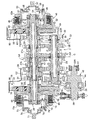
図2を併せて参照して、前記歯車変速機Tは、前記クランクシャフト12と平行な軸線を有して同軸に配置される第1および第2メインシャフト27,28と、第1および第2メインシャフト27,28と平行な軸線を有するカウンタシャフト29と、選択的に確立されるようにして第1および第2メインシャフト27,28および前記カウンタシャフト29間に設けられる複数変速段のギヤ列たとえば第1〜第6速用ギヤ列G1,G2,G3,G4,G5,G6とで構成されており、第1メインシャフト27、第2メインシャフト28およびカウンタシャフト29はクランクケース13で回転自在に支承される。
Referring also to FIG. 2, the gear transmission T includes first and second
而して第1メインシャフト27は、クランクケース13における下ケース半体22の右側壁22Rを回転自在に貫通するものであり、第1メインシャフト27および前記右側壁22R間には第1軸受である第1ボールベアリング33が介装される。また第2メインシャフト28は、前記下ケース半体22の左側壁22Lを回転自在に貫通するものであり、第2メインシャフト28および前記左側壁22L間には第2軸受である第2ボールベアリング34が介装され、第1ボールベアリング33は第2ボールベアリング34よりも大径に形成される。
Thus, the first
一方、カウンタシャフト29の一端部は、前記下ケース半体22の右側壁22Rに第1ニードルベアリング35を介して回転自在に支承され、カウンタシャフト29の他端部は、前記下ケース半体22の左側壁22Lに第3ボールベアリング36を介して回転自在に支承される。
On the other hand, one end of the
さらに前記下ケース半体22には、前記カウンタシャフト29からの回転動力が伝達されるファイナルシャフト30が、前記カウンタシャフト29と平行な軸線まわりに回転自在に支承されており、ファイナルシャフト30の一端部は下ケース半体22の左側壁22Lに第2ニードルベアリング37を介して回転自在に支承される。また前記ファイナルシャフト30は、下ケース半体22の右側壁22Rを回転自在に貫通するものであり、前記ファイナルシャフト30および前記右側壁22R間には第4ボールベアリング38および環状のシール部材39が介装される。前記下ケース半体22の右側壁22Rから突出した前記ファイナルシャフト30の突出端部には、図示しない駆動輪(後輪)に回転動力を伝達する出力部材としての駆動スプロケット40が設けられ、該駆動スプロケット40にはチェーン41が巻き掛けられる。
Further, a
前記カウンタシャフト29および前記ファイナルシャフト30間には、前記カウンタシャフト29から前記ファイナルシャフト30に回転動力を伝達するファイナルギヤ列42が設けられており、このファイナルギヤ列42は、第2速用ギヤ列G2および第2ボールベアリング34間で前記カウンタシャフト29に一体に設けられたファイナルドライブギヤ43と、該ファイナルドライブギヤ43に噛合して前記ファイナルシャフト30に相対回転不能に設けられるファイナルドリブンギヤ44とから成り、そのファイナルドリブンギヤ44は、前記カウンタシャフト29および前記ファイナルシャフト30の軸線に直交する方向から見て第2ボールベアリング34に少なくとも一部が重なるようにして前記ファイナルシャフト30に設けられる。
A
図3を併せて参照して、第1および第2メインシャフト27,28の相互に反対側の端部には、前記クランクシャフト12から第1および第2メインシャフト27,28に伝達される回転動力を断・接する第1および第2クラッチ45,46が配設されており、第1および第2メインシャフト27,28の第1および第2クラッチ45,46とは反対側の端部が相対回転を可能として相互に嵌装、支持される。
Referring also to FIG. 3, the rotation transmitted from the
第1メインシャフト27は、大径部27aと、第2メインシャフト28に嵌合される小径部27bとが同軸にかつ一体に連なって成るものであり、第1メインシャフト27の小径部26bおよび第2メインシャフト28間には複数たとえば一対の第4ニードルベアリング47,47が介装される。
The first
第1メインシャフト27の大径部27および前記カウンタシャフト29間には、6変速段のギヤ列のうち奇数段のギヤ列である第1、第3および第5速用ギヤ列G1,G3,G5が択一的に確立し得るようにして設けられ、第2メインシャフト28および前記カウンタシャフト29間には、6変速段のギヤ列のうち偶数段のギヤ列である第2、第4および第6速用ギヤ列G2,G4,G6が択一的に確立し得るようにして設けられる。
Between the large-
しかも第1メインシャフト27および前記カウンタシャフト29間に設けられる第1、第3および第5速用ギヤ列G1,G3,G5と、第2メインシャフト28および前記カウンタシャフト29間に設けられる第2、第4および第6速用ギヤ列G2,G4,G6とは、前記クランクシャフト12の軸方向でのエンジンセンターCの両側に分かれて配置される。
In addition, first, third and fifth speed gear trains G1, G3 and G5 provided between the first
第1メインシャフト27および下ケース半体22の右側壁22R間に介装される第1ボールベアリング33と、第2メインシャフト28および前記下ケース半体22の左側壁22L間に介装される第2ボールベアリング34は、6変速段のギヤ列G1〜G6を相互間に挟むように配置されるものであり、第1メインシャフト27の第1クラッチ45とは反対側の端部すなわち小径部27bの端部は、第2メインシャフト28内で第2ボールベアリング34に対応する部分まで延出される。
The
前記クランクシャフト12からの回転動力の第1メインシャフト27への伝達を断・接する第1クラッチ45は、第1メインシャフト27の右端部に相対回転自在に支承される第1クラッチアウタ48と、第1クラッチアウタ48に係合される複数枚の第1摩擦板49,49…と、第1メインシャフト27に相対回転不能に結合される第1クラッチインナ50と、第1摩擦板49,49…と交互に配置されて第1クラッチインナ50に係合される複数枚の第2摩擦板51,51…と、交互に配置される第1および第2摩擦板49,49…;51,51…のうち軸方向内方の摩擦板に対向して第1クラッチインナ50に一体に設けられる第1受圧板52と、第1クラッチインナ50に相対摺動可能に嵌合されるようにして有底円筒状に構成されるとともに交互に配置される第1および第2摩擦板49,49…;51,51…のうち軸方向外方の摩擦板に対向する第1押圧部53aが半径方向外方に張り出すようにして一体に設けられる第1押圧部材53と、第1押圧部53aが第1受圧板52から離反する側に第1押圧部材53を付勢するようにして第1クラッチインナ50および第1押圧部材53間に介装される第1係合解除用スプリング54と、第1押圧部材53からの離脱が阻止されるようにして第1押圧部材53内に同軸に挿入される円板状の第1伝達部材55と、第1伝達部材55を第1押圧部材53の開口端側に付勢するばね力を発揮して第1押圧部材53および第1伝達部材55間に設けられる第1プッシュスプリング56と、第1伝達部材55と同軸に配置されるとともに第1伝達部材55に第1レリーズベアリング58を介して連結される第1作動部材57とを備え、第1作動部材57が図示しないアクチュエータによって軸方向に駆動される。
A
このような第1クラッチ45では、アクチュエータの非作動状態では、第1押圧部材53が第1係合解除用スプリング54で係合解除側に付勢されているので、第1クラッチ45は動力伝達を遮断した切断状態にある。次いでアクチュエータを作動せしめて第1作動部材57を軸方向に作動せしめると、その駆動力が、第1レリーズベアリング58から第1伝達部材55、第1プッシュスプリング56を介して第1押圧部材53に伝達され、第1押圧部材53が第1係合解除用スプリング54を圧縮しながら第1および第2摩擦板49,49…;51,51…を第1受圧板52側に押圧して相互に摩擦係合せしめ、第1クラッチアウタ48および第1クラッチインナ50が結合された接続状態となる。
In such a first clutch 45, when the actuator is in an inoperative state, the first pressing
而して第1作動部材57の軸方向作動に応じて第1プッシュスプリング56が圧縮され、第1プッシュスプリング56の弾発力が第1係合解除用スプリング54の弾発力を超えると、第1プッシュスプリング56の圧縮量に応じた推力で第1押圧部材53が駆動されて第1および第2摩擦板49,49…;51,51…にクラッチ圧着力が作用し、そのクラッチ圧着力に応じたクラッチ容量で第1クラッチ45が接続状態となる。すなわち第1作動部材57の位置と、第1クラッチ45のトルク伝達容量との間にリニアな関係を持たせることができ、アクチュエータの作動制御によって第1クラッチ45のトルク伝達容量を高精度に制御することが可能となる。
Thus, when the
ところで第1メインシャフト27には、前記クランクシャフト12からの回転動力が第1一次減速ギヤ列59および第1クラッチ45を介して伝達されるものであり、第1一次減速ギヤ列59は、前記クランクシャフト12の右側端部に固定される第1一次ドライブギヤ60と、第1一次ドライブギヤ60に噛合して第1メインシャフト27と同軸に配置される第1一次ドリブンギヤ61とで構成される。第1一次ドリブンギヤ61は、第1ボールベアリング33と、第1クラッチ45の第1クラッチアウタ48との間に配置されて第1メインシャフト27に相対回転可能に支承され、第1ダンパゴム62を介して第1クラッチアウタ48に連結される。
By the way, the rotational power from the
而して第1ボールベアリング33は、第1一次ドリブンギヤ61と、第1メインシャフト27および前記カウンタシャフト29間に設けられる複数変速段のギヤ列のうち最も第1クラッチ45に近接して第1一次ドリブンギヤ61よりも軸方向内方に配置されるギヤ列すなわち第1速用ギヤ列G1との間であって、前記カウンタシャフト29の第1クラッチ45側の端部に側面視で少なくとも一部を重ねる位置に配置される。
Thus, the
前記クランクシャフト12からの回転動力の第2メインシャフト28への伝達を断・接する第2クラッチ46は、第2メインシャフト28の右端部に相対回転自在に支承される第2クラッチアウタ68と、第2クラッチアウタ68に係合される複数枚の第3摩擦板69,69…と、第2メインシャフト28に相対回転不能に結合される第2クラッチインナ70と、第3摩擦板69,69…と交互に配置されて第2クラッチインナ70に係合される複数枚の第4摩擦板71,71…と、交互に配置される第3および第4摩擦板69,69…;71,71…のうち軸方向内方の摩擦板に対向して第2クラッチインナ70に一体に設けられる第2受圧板72と、第2クラッチインナ70に相対摺動可能に嵌合されるようにして有底円筒状に構成されるとともに交互に配置される第3および第4摩擦板69,69…;71,71…のうち軸方向外方の摩擦板に対向する第2押圧部73aが半径方向外方に張り出すようにして一体に設けられる第2押圧部材73と、第2押圧部73aが第2受圧板72から離反する側に第2押圧部材73を付勢するようにして第2クラッチインナ70および第2押圧部材73間に介装される第2係合解除用スプリング74と、第2押圧部材73からの離脱が阻止されるようにして第2押圧部材72内に同軸に挿入される円板状の第2伝達部材75と、第2伝達部材75を第2押圧部材73の開口端側に付勢するばね力を発揮して第2押圧部材73および第2伝達部材75間に設けられる第2プッシュスプリング76と、第2伝達部材75と同軸に配置されるとともに第2伝達部材75に第2レリーズベアリング78を介して連結される第2作動部材77とを備え、第2作動部材77が図示しないアクチュエータによって軸方向に駆動される。
The second clutch 46 for connecting / disconnecting the transmission of the rotational power from the
このような第2クラッチ46は、第1クラッチ45と同様に断・接作動するものであり、第2作動部材77の位置と、第2クラッチ46のトルク伝達容量との間にリニアな関係を持たせることができ、アクチュエータの作動制御によって第2クラッチ46のトルク伝達容量を高精度に制御することが可能となる。
Such a second clutch 46 is operated to be disconnected and connected in the same manner as the first clutch 45, and has a linear relationship between the position of the
ところで第2メインシャフト28には、前記クランクシャフト12からの回転動力が第2一次減速ギヤ列79および第2クラッチ46を介して伝達されるものであり、第2一次減速ギヤ列79は、前記クランクシャフト12の左側端部に固定される第2一次ドライブギヤ80と、第2一次ドライブギヤに噛合して第2メインシャフト28と同軸に配置される第2一次ドリブンギヤ81とで構成される。第2一次ドリブンギヤ81は、第2ボールベアリング34と、第2クラッチ46の第2クラッチアウタ68との間に配置されて第2メインシャフト28に相対回転可能に支承され、第2ダンパゴム82を介して第2クラッチアウタ68に連結される。
Incidentally, the rotational power from the
次にこの実施の形態の作用について説明すると、第1および第2メインシャフト27,28の第1および第2クラッチ45,46とは反対側の端部が相対回転を可能として相互に嵌装、支持されるので、第1および第2メインシャフト27,28とは反対側でクランクケース13と第1および第2メインシャフト27,28との間に軸受を設けることが不要であり、部品点数を低減することができるとともに、第1および第2メインシャフト27,28の全体軸長を短くすることができ、第1および第2メインシャフト27,28の軸方向で車両用パワーユニットPの小型化を図ることができる。
Next, the operation of this embodiment will be described. The ends of the first and second
また第1メインシャフト27およびカウンタシャフト29間に設けられる第1、第3および第5速用ギヤ列G1,G3,G5と、第2メインシャフト28およびカウンタシャフト29間に設けられる第2、第4および第6速用ギヤ列G2,G4,G6とが、前記クランクシャフト12の軸方向でのエンジンEセンターの両側に分かれて配置されるので、クランクシャフト12の軸方向での重量バランスを良好なものとすることができる。
The first, third and fifth speed gear trains G1, G3 and G5 provided between the first
また第1メインシャフト27が第2メインシャフト28に相対回転自在に嵌合され、第1メインシャフト27およびクランクケース13間に介装される第1ボールベアリング33と、第2メインシャフト28およびクランクケース13間に介装される第2ボールベアリング34とが、第1〜第6速用ギヤ列G1〜G6を相互間に挟む位置に配置され、第1メインシャフト27の第1クラッチ45とは反対側の端部が、第2メインシャフト28内で第2ボールベアリング34に対応する部分まで延出されるので、第1メインシャフト27の第1クラッチ45とは反対側の端部ならびに第2メインシャフト28の第2クラッチ46とは反対側の端部を相互に安定的に支持しつつ第1および第2メインシャフト27,28の全体軸長を短くして、車両用パワーユニットPを第1および第2メインシャフト27,28の軸方向でより小型化することができる。
Also, the first
また第1メインシャフト27が、大径部27aと、第2メインシャフト28に嵌合される小径部27bとが同軸にかつ一体に連なって成るものであるので、第2メインシャフト28が大径化することを回避することができる。しかも第1メインシャフト27の小径部27bおよび第2メインシャフト28間に第4ニードルベアリング47…が介装されるので、小径部27bの磨耗を防止しつつ第2メインシャフト28および第1メインシャフト27の相互支持を可能とし、小径部27bおよび第2メインシャフト28間にボールベアリングが介装される場合に比べて、第2メインシャフト28の小径化を図ることができる。
Further, since the first
またクランクケース13には、駆動輪に回転動力を伝達する駆動スプロケット40がクランクケース13からの突出端部に設けられるファイナルシャフト30が、カウンタシャフト29と平行な軸線まわりに回転自在に支承され、カウンタシャフト29からファイナルシャフト30に回転動力を伝達するファイナルギヤ列42の一部を構成するファイナルドリブンギヤ44が、カウンタシャフト29およびファイナルシャフト30の軸線に直交する方向から見て第2ボールベアリング34に少なくとも一部が重なるようにしてファイナルシャフト30に設けられるので、ファイナルシャフト30の軸長を短くしつつ、第2ボールベアリング34およびファイナルドリブンギヤ44を近接配置することができる。
The
さらに第2ボールベアリング34よりも大径である第1ボールベアリング33が、クランクシャフト12および第1メインシャフト27間に設けられる第1一次減速ギヤ列59の一部を構成して第1メインシャフト27と同軸に配置される第1一次ドリブンギヤ61と、第1メインシャフト27およびカウンタシャフト29間に設けられる第1、第3および第5速用ギヤ列G1,G3,G5のうち最も第1クラッチ45に近接して第1一次ドリブンギヤ61よりも軸方向内方に配置される第1速用ギヤ列G1との間であって前記カウンタシャフト29の第1クラッチ45側の端部に側面視で少なくとも一部を重ねる位置に配置されるので、第1ボールベアリング33の周辺のレイアウトに制約をかけることなく比較的大径の第1ボールベアリング33を配置し、第1ボールベアリング33を耐久性のあるものとすることができる。
Further, the
以上、本発明の実施の形態について説明したが、本発明は上記実施の形態に限定されるものではなく、特許請求の範囲に記載された本発明を逸脱することなく種々の設計変更を行うことが可能である。 Although the embodiments of the present invention have been described above, the present invention is not limited to the above-described embodiments, and various design changes can be made without departing from the present invention described in the claims. Is possible.
12・・・クランクシャフト
13・・・エンジンケースであるクランクケース
27・・・第1メインシャフト
27a・・・大径部
27b・・・小径部
28・・・第2メインシャフト
29・・・カウンタシャフト
30・・・ファイナルシャフト
33・・・第1軸受である第1ボールベアリング
34・・・第2軸受である第2ボールベアリング
40・・・出力部材である駆動スプロケット
42・・・ファイナルギヤ列
44・・・ファイナルドリブンギヤ
45・・・第1クラッチ
46・・・第2クラッチ
47・・・ニードルベアリングである第4ニードルベアリング
59・・・一次減速ギヤ列である第1一次減速ギヤ列
61・・・一次ドリブンギヤである第1一次ドリブンギヤ
C・・・エンジンセンター
G1,G2,G3,G4,G5,G6・・・ギヤ列
P・・・車両用パワーユニット
DESCRIPTION OF
Claims (5)
前記第1メインシャフト(27)の前記第1クラッチ(45)とは反対側の端部が、前記第2メインシャフト(28)の前記第2クラッチ(46)とは反対側の端部内に相対回転自在に嵌合、支持され、前記第1メインシャフト(27)および前記エンジンケース(13)間に介装される第1軸受(33)と、前記第2メインシャフト(28)および前記エンジンケース(13)間に介装される第2軸受(34)とが、前記複数変速段のギヤ列(G1〜G6)を相互間に挟む位置に配置されると共に、前記第1メインシャフト(27)の前記第1クラッチ(45)とは反対側の端部が、前記第2メインシャフト(28)内で前記第2軸受(34)に対応する位置まで延出され、前記エンジンケース(13)には、駆動輪に回転動力を伝達する出力部材(40)が前記エンジンケース(13)からの突出端部に設けられるファイナルシャフト(30)が、前記カウンタシャフト(29)と平行な軸線まわりに回転自在に支承され、前記カウンタシャフト(29)から前記ファイナルシャフト(30)に回転動力を伝達するファイナルギヤ列(42)の一部を構成するファイナルドリブンギヤ(44)が、前記カウンタシャフト(29)および前記ファイナルシャフト(30)の軸線に直交する方向から見て前記第2軸受(34)に少なくとも一部が重なるようにして前記ファイナルシャフト(30)に設けられることを特徴とする車両用パワーユニット。 A crankshaft (12) extending in the lateral direction of the vehicle, said first and second main shafts having an axis parallel to the crankshaft (12) (27, 28), which first and second main shafts (27, counter shaft having an axis parallel to the 28) and (29) are rotatably supported by the engine case (13), between said first and second said counter shaft and a main shaft (27, 28) (29) gear trains of a plurality shift stage is established selectively in (G1, G2, G3, G4 , G5, G6) are provided, wherein the crankshaft (12) first and second main shafts (27, 28 mutually opposite ends of said first and second clutch rotational power disconnects. (45, 46) the first and second main shafts (27, 28) which) is transmitted to the The vehicle power unit which is disposed,
The end of the first main shaft (27) opposite to the first clutch (45) is relatively within the end of the second main shaft (28) opposite to the second clutch (46). A first bearing (33) that is rotatably fitted and supported and is interposed between the first main shaft (27) and the engine case (13), the second main shaft (28), and the engine case (13) A second bearing (34) interposed therebetween is disposed at a position sandwiching the gear trains (G1 to G6) of the plurality of shift stages, and the first main shaft (27). The end opposite to the first clutch (45) extends to a position corresponding to the second bearing (34) in the second main shaft (28), and is connected to the engine case (13). Transmits rotational power to the drive wheels A final shaft (30) having a force member (40) provided at an end protruding from the engine case (13) is rotatably supported about an axis parallel to the counter shaft (29), and the counter shaft (29 The final driven gear (44) that constitutes a part of the final gear train (42) that transmits rotational power to the final shaft (30) is orthogonal to the axis of the counter shaft (29) and the final shaft (30). The vehicle power unit is provided on the final shaft (30) so as to at least partly overlap the second bearing (34) when viewed from the direction in which the power is applied.
Priority Applications (1)
| Application Number | Priority Date | Filing Date | Title |
|---|---|---|---|
| JP2010190375A JP5426504B2 (en) | 2010-08-27 | 2010-08-27 | Power unit for vehicle |
Applications Claiming Priority (1)
| Application Number | Priority Date | Filing Date | Title |
|---|---|---|---|
| JP2010190375A JP5426504B2 (en) | 2010-08-27 | 2010-08-27 | Power unit for vehicle |
Publications (2)
| Publication Number | Publication Date |
|---|---|
| JP2012047272A JP2012047272A (en) | 2012-03-08 |
| JP5426504B2 true JP5426504B2 (en) | 2014-02-26 |
Family
ID=45902377
Family Applications (1)
| Application Number | Title | Priority Date | Filing Date |
|---|---|---|---|
| JP2010190375A Expired - Fee Related JP5426504B2 (en) | 2010-08-27 | 2010-08-27 | Power unit for vehicle |
Country Status (1)
| Country | Link |
|---|---|
| JP (1) | JP5426504B2 (en) |
Family Cites Families (5)
| Publication number | Priority date | Publication date | Assignee | Title |
|---|---|---|---|---|
| JPS55103152A (en) * | 1979-01-30 | 1980-08-07 | Nissan Motor Co Ltd | Transmission gear for automobile |
| JPS58124851A (en) * | 1982-01-15 | 1983-07-25 | Aisin Seiki Co Ltd | Multistage transmission for car |
| JPH0727186A (en) * | 1993-07-09 | 1995-01-27 | Mazda Motor Corp | Transfer device and assembling method therefor |
| JP4757094B2 (en) * | 2006-05-23 | 2011-08-24 | 本田技研工業株式会社 | Transmission and method of assembling the same |
| JP5180778B2 (en) * | 2008-10-30 | 2013-04-10 | ヤマハ発動機株式会社 | Engine unit and motorcycle equipped with the same |
-
2010
- 2010-08-27 JP JP2010190375A patent/JP5426504B2/en not_active Expired - Fee Related
Also Published As
| Publication number | Publication date |
|---|---|
| JP2012047272A (en) | 2012-03-08 |
Similar Documents
| Publication | Publication Date | Title |
|---|---|---|
| US8469848B2 (en) | Vehicular drive apparatus | |
| JP5163722B2 (en) | Hybrid drive device | |
| US7694792B2 (en) | Twin clutch device | |
| US8567276B2 (en) | Engine unit, and motorcycle equipped therewith | |
| US8662233B2 (en) | Engine unit and two-wheeled motor vehicle with same | |
| US9939031B2 (en) | Hybrid automotive transmission arrangement | |
| US8302752B2 (en) | Multi-plate clutch | |
| US7926636B2 (en) | Twin clutch apparatus for power unit, power unit incorporating same, and vehicle incorporating same | |
| US20110005345A1 (en) | Actuating arrangement for shift elements of a transmission | |
| JP2008110665A (en) | Vehicular power unit | |
| US20100229668A1 (en) | Multiple-Ratio Transmission with Concentric Offset Shift Forks | |
| WO2008041429A1 (en) | Shift control device for vehicle transmission | |
| US8573085B2 (en) | Power unit for vehicle | |
| JP5063760B2 (en) | forklift | |
| JP2011256916A (en) | Clutch device | |
| JP4599155B2 (en) | Double clutch device | |
| JP4662899B2 (en) | Multi-plate clutch | |
| JP4929246B2 (en) | Multi-plate clutch | |
| JP5426504B2 (en) | Power unit for vehicle | |
| JP5210210B2 (en) | Power unit for vehicle | |
| JP5513323B2 (en) | Power unit for vehicle | |
| JP4474358B2 (en) | Twin clutch device | |
| JP4773084B2 (en) | Double clutch device | |
| JP2857651B2 (en) | Automatic transmission | |
| JP6120471B2 (en) | Power transmission device for vehicle |
Legal Events
| Date | Code | Title | Description |
|---|---|---|---|
| A621 | Written request for application examination |
Free format text: JAPANESE INTERMEDIATE CODE: A621 Effective date: 20121127 |
|
| A977 | Report on retrieval |
Free format text: JAPANESE INTERMEDIATE CODE: A971007 Effective date: 20130815 |
|
| A131 | Notification of reasons for refusal |
Free format text: JAPANESE INTERMEDIATE CODE: A131 Effective date: 20130828 |
|
| A521 | Written amendment |
Free format text: JAPANESE INTERMEDIATE CODE: A523 Effective date: 20130927 |
|
| TRDD | Decision of grant or rejection written | ||
| A01 | Written decision to grant a patent or to grant a registration (utility model) |
Free format text: JAPANESE INTERMEDIATE CODE: A01 Effective date: 20131030 |
|
| A61 | First payment of annual fees (during grant procedure) |
Free format text: JAPANESE INTERMEDIATE CODE: A61 Effective date: 20131128 |
|
| R150 | Certificate of patent or registration of utility model |
Free format text: JAPANESE INTERMEDIATE CODE: R150 Ref document number: 5426504 Country of ref document: JP Free format text: JAPANESE INTERMEDIATE CODE: R150 |
|
| LAPS | Cancellation because of no payment of annual fees |