JP5422901B2 - Joining method and joining apparatus - Google Patents
Joining method and joining apparatus Download PDFInfo
- Publication number
- JP5422901B2 JP5422901B2 JP2008084354A JP2008084354A JP5422901B2 JP 5422901 B2 JP5422901 B2 JP 5422901B2 JP 2008084354 A JP2008084354 A JP 2008084354A JP 2008084354 A JP2008084354 A JP 2008084354A JP 5422901 B2 JP5422901 B2 JP 5422901B2
- Authority
- JP
- Japan
- Prior art keywords
- substrate
- substrates
- pair
- wafer
- correction
- Prior art date
- Legal status (The legal status is an assumption and is not a legal conclusion. Google has not performed a legal analysis and makes no representation as to the accuracy of the status listed.)
- Active
Links
Images


Classifications
-
- H10W72/0711—
Landscapes
- Container, Conveyance, Adherence, Positioning, Of Wafer (AREA)
Description
本発明は、接合方法に関する。より詳細には、ウエハ等の基板を貼り合わせる場合の接合方法および接合装置に関する。 The present invention relates to a joining method. More specifically, the present invention relates to a bonding method and a bonding apparatus for bonding substrates such as wafers.
各々に素子および回路が形成された基板を積層した積層型の半導体装置がある(特許文献1参照)。積層型の半導体装置は、立体的な構造を形成することにより、実装面積を拡大することなく実効的に高い実装密度を有する。また、積層された基板相互の配線が短いので、動作速度の向上にも寄与するといわれている。 There is a stacked semiconductor device in which substrates each having an element and a circuit formed thereon are stacked (see Patent Document 1). A stacked semiconductor device has a high mounting density by forming a three-dimensional structure without increasing the mounting area. Further, it is said that the wiring between the stacked substrates is short, which contributes to an improvement in operation speed.
基板を貼り合わせる場合には、互いに平行に保持された一対の基板を加圧して圧接させる。このため、一対の基板を平行に保持して加圧する接合装置が用いられる(特許文献2参照)。
接合する一対の基板を完全に平行にすることは難しく、一方の基板が僅かに傾斜した状態で加圧が開始される場合がある。このような場合、傾いた基板が加圧された状態で揺動して、基板の面と平行な方向に位置ずれが生じる場合がある。このようなずれが、接合面に形成されたバンプの径よりも大きい場合は基板相互の電気的接続がとれず、積層半導体装置としての機能が得られない。また、接合装置による基板の保持が強固な場合は、位置ずれを生じる応力が基板自体に作用して、基板が損傷する場合もある。 It is difficult to make the pair of substrates to be joined completely parallel, and pressurization may be started in a state where one substrate is slightly inclined. In such a case, the tilted substrate may oscillate in a pressurized state, and a positional shift may occur in a direction parallel to the surface of the substrate. When such a deviation is larger than the diameter of the bump formed on the bonding surface, the substrates cannot be electrically connected to each other, and a function as a laminated semiconductor device cannot be obtained. In addition, when the substrate is firmly held by the bonding apparatus, a stress that causes a positional shift may act on the substrate itself, and the substrate may be damaged.
そこで、上記課題を解決すべく、本発明の第1の形態として、一対の基板の一方の基板を固定する固定段階と、一方の基板に対向して配置される他方の基板を揺動自在に保持する保持段階と、一方の基板の面方向に沿った他方の基板の位置を合わせる位置合わせ段階と、他方の基板を一方の基板に向かって変位させる変位段階と、他方の基板の変位により相互に密着した一対の基板を加圧して、一対の基板を相互に接合する圧接段階とを含む接合方法であって、位置合わせ段階は、他方の基板の揺動により生じる一方の基板の面方向に沿った他方の基板の位置ずれを打ち消すように、他方の基板の位置を補正する位置補正段階を含む接合方法が提供される。 Therefore, in order to solve the above-mentioned problem, as a first embodiment of the present invention, a fixing stage for fixing one substrate of a pair of substrates, and the other substrate disposed opposite to the one substrate can be swung freely. A holding step, a positioning step for aligning the other substrate along the surface direction of one substrate, a displacement step for displacing the other substrate toward the one substrate, and a displacement of the other substrate. Pressurizing a pair of substrates in close contact with each other and joining the pair of substrates to each other, wherein the alignment step is performed in the surface direction of one substrate caused by the oscillation of the other substrate. A bonding method is provided that includes a position correction step of correcting the position of the other substrate so as to cancel the misalignment of the other substrate along.
また、本発明の第2の形態として、一対の基板の一方の基板を固定する固定部と、一方の基板に対向して配置される他方の基板を揺動自在に保持する保持部と、一方の基板の面方向に沿った他方の基板の位置を合わせる位置合わせ部と、他方の基板を一方の基板に向かって変位させ、相互に密着した一対の基板を加圧して、一対の基板を相互に接合する駆動部と、他方の基板の揺動により生じる一方の基板の面方向に沿った他方の基板の位置ずれを打ち消すように他方の基板の位置を補正すべく、位置合わせ部の作動を制御する補正制御部とを備える接合装置が提供される。 Further, as a second embodiment of the present invention, a fixing portion for fixing one substrate of a pair of substrates, a holding portion for swingably holding the other substrate disposed opposite to the one substrate, A positioning unit that aligns the position of the other substrate along the surface direction of the substrate, and the other substrate is displaced toward the one substrate, and the pair of substrates that are in close contact with each other are pressurized, so that the pair of substrates is And an operation of the alignment unit to correct the position of the other substrate so as to cancel the positional deviation of the other substrate along the surface direction of the one substrate caused by the swing of the other substrate. There is provided a joining apparatus including a correction control unit for controlling.
なお、上記の発明の概要は、本発明の全ての特徴を列挙したものではない。また、これらの特徴群のサブコンビネーションも発明となり得る。 The above summary of the invention does not enumerate all the features of the present invention. Further, a sub-combination of these feature groups can be an invention.
以下、発明の実施の形態を通じて本発明を説明する。以下に記載する実施形態は、特許請求の範囲にかかる発明を限定するものではない。また、実施形態の中で説明されている特徴の組み合わせ全てが発明の解決に必須であるとは限らない。 Hereinafter, the present invention will be described through embodiments of the invention. The embodiments described below do not limit the invention according to the claims. In addition, not all combinations of features described in the embodiments are essential for the solution of the invention.
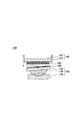
図1は、接合装置100の構造を模式的に示す断面図である。接合装置100は、枠体110の内側に配置された、駆動部120、昇降テーブル130、固定テーブル140、ロードセル150および、制御部180を備える。
FIG. 1 is a cross-sectional view schematically showing the structure of the
枠体110は、互いに平行で水平な天板112および底板116と、天板112および底板116を結合する複数の支柱114とを備える。天板112、支柱114および底板116は、それぞれ高剛性な材料により形成され、後述する接合におけるウエハ162、164への加圧の反力が作用した場合も変形が生じない。
The
枠体110の内側において、底板116の上には、駆動部120が配置される。駆動部120は、底板116の上面に固定されたシリンダ124と、シリンダ124の内側に配置されたピストン122とを有する。ピストン122は、図示されていない流体回路、カム、輪列等により駆動されて、図中に矢印Zにより示す、底板116に対して直角な方向に昇降する。また、ピストン122は、複数の水平なキー126を有する平面を上端に有する。キー126は紙面に対して奥行き方向に形成される。
The
ピストン122の上端には、昇降テーブル130が装着される。昇降テーブル130は、基板保持部132、球面座134、Xステージ136およびYステージ138を有する。Yステージ138は、キー126と嵌合するキー溝を下面に有して、ピストン122の上面に装着される。これにより、Yステージ138は、ピストン122の頂部において紙面に直交する方向に変位する。
A lifting table 130 is attached to the upper end of the
Xステージ136は、Yステージ138の上面に装着され、紙面と平行に形成された嵌め合い構造によりYステージ138と嵌合する。これにより、Xステージ136は、紙面と平行に変位する。これらXステージ136およびYステージ138の動作を併せることにより、X−Y平面上の任意の変位が得られる。球面座134は、Xステージ136の上面に形成された球面状の凹部と相補的な形状の下面を有し、Xステージ136上に揺動自在に支持される。
The
このように、接合装置100は、Xステージ136およびYステージ138を含む基板変位機構を備える。この基板変位機構は、ウエハ162、164を位置合わせする場合に用いることができる他、ウエハ164の位置を補正する場合にも仕様できる。これにより、ハードウェハ資源を増加させることなく、後述の位置補正を実行できる。
As described above, the
球面座134の上面には、基板保持部132が搭載される。基板保持部132は、静電吸着、負圧吸着等により上面にウエハ164を吸着する。これにより、基板保持部132に保持されたウエハ164の移動または脱落が抑制される。また、基板保持部132が揺動した場合は、基板保持部132に吸着されたウエハ164も共に揺動する。
A
一方、固定テーブル140は、基板保持部142および複数の懸架部144を有する。懸架部144は、天板112の下面から垂下される。基板保持部142は、懸架部144の下端近傍において下方から支持され、昇降テーブル130に対向して配置される。基板保持部142も、静電吸着、負圧吸着等による吸着機構を有し、下面にウエハ164を吸着して保持する。
On the other hand, the fixed table 140 includes a
また、懸架部144は、基板保持部142を下方から支持する一方、上方への移動は規制しない。しかしながら、基板保持部142および天板112の間には、複数のロードセル150が挟まれる。これにより、基板保持部142に保持されたウエハ162に印加された圧力が検出されると共に、基板保持部142の上方への変位が規制される。
The
また、ロードセル150は、基板保持部142背面の単一平面上の異なる位置において荷重を検出する。これにより、ロードセル150相互の検出値の相違に基づいて、ウエハ162のどの位置に荷重が印加されたかを算出することができる。
Further, the
こうして、一対のウエハ162、164の一方のウエハ162を水平に固定する固定テーブル140と、一対のウエハ162、164の他方のウエハ164を、水平面に対して揺動自在に保持する昇降テーブル130と、他方のウエハ164を前記一方のウエハ162の下面に沿った方向すなわち水平方向に位置合わせするXステージ136およびYステージ138と、他方のウエハ164を一方のウエハ162に向かって変位させ、相互に密着した一対のウエハ162、164を加圧して、一対のウエハ162、164を相互に接合する駆動部120と、Xステージ136およびYステージ138を動作させて、他方のウエハ164の一方のウエハ162に対する水平方向の位置合わせを補正して、他方のウエハ164が一方のウエハ162に当接してから密着するまでの間の他方のウエハ164の揺動により生じる、他方のウエハ164の一方のウエハ162に対する水平方向の位置ずれを打ち消す補正制御部180とを備える接合装置100が形成される。以下、この接合装置100の制御部180において実行される位置補正について説明する。
Thus, the fixed table 140 that horizontally fixes one
なお、図1に示す状態は、接合装置100の動作において初期状態に相当する。この状態では、駆動部120のピストン122がシリンダ124の中に引き込まれており、昇降テーブル130は降下している。従って、昇降テーブル130および固定テーブル140に保持されたウエハ162、164の間には広い間隙がある。接合の対象となる一対のウエハ162、164は、上記間隙に対して側方から装入されて、昇降テーブル130または固定テーブル140に保持される。
The state shown in FIG. 1 corresponds to the initial state in the operation of the
ウエハ164を保持した昇降テーブル130は、Xステージ136およびYステージ138を動作させることにより、保持されたウエハ164を水平に移動させて、ウエハ164に対して水平方向に位置合わせすることができる。
The elevating table 130 holding the
ウエハ164を保持した基板保持部132は、駆動部120の動作により上昇させることができる。これにより、ウエハ164は、やがてウエハ162に当接する。ウエハ164に対して外力が作用した場合、球面座134により基板保持部132が揺動するので、駆動部120により加圧することにより、ウエハ162、164は相互に密着する。なお、球面座134による揺動の揺動中心Cは、昇降テーブル130の基板保持部132の上面に位置するものとする。
The
こうして接合されたウエハ162、164では、各々の表面に形成された信号端子が相互に接続され、全体でひとつの回路を形成する。このようにして、積層型半導体装置を製造できる。なお、積層型半導体装置の製造工程においては、ウエハ162、164の間を接着材等により接着して、接合を恒久的にする段階が導入される場合もある。
In the
図2は、一方が傾斜したウエハ162、164当接させて加圧する場合に生じる現象を示す。ここでは、水平なウエハ162に対して、傾斜角度θで傾斜したウエハ164の縁部が当接した場合を例に挙げて、ウエハ164縁部の当接点Mが、ウエハ162の縁部に対して生じた位置ずれEについて説明する。
FIG. 2 shows a phenomenon that occurs when the
なお、ウエハ162、164は、水平方向について中心位置が一致するように位置合わせされている。また、傾斜したウエハ164の揺動中心Cは、基板保持部132の表面に位置して、ウエハ164の接合面からは距離Δh離れているものとする。
The
全体の位置ずれEは、ウエハ162、164の寸法(半径D)およびウエハ164の傾斜角度θに依存する位置ずれE1と、ウエハ164の接合面および揺動中心Cの間隔Δh並びにウエハ164の傾斜角度θに依存する位置ずれE2とを含み、下記の式1に示す関係を有する。
E=E1+E2
E1=D(1−cosθ)
E2=Δh・sinθ ・・・[式1]
The total positional deviation E includes the positional deviation E 1 depending on the dimensions (radius D) of the
E = E 1 + E 2
E 1 = D (1-cos θ)
E 2 = Δh · sin θ (Formula 1)
換言すれば、ウエハ162、164を接合する場合の、ウエハ164の寸法(半径D)、傾斜角度θ、揺動中心および接合面の間隔Δhに基づいて、位置ずれEを予測することができる。従って、位置ずれEを打ち消すように、ウエハ162、164の位置合わせを補正することができる。
In other words, when the
上記補正における補正量は、ウエハ162、164の当接箇所Mの水平位置を検出する当接位置検出段階を実行して、検出された当接位置に基づいて算出できる。また、駆動部120による昇降テーブル130の変位段階において、他方のウエハ164が一方のウエハ162に当接した時点で、他方のウエハ164の水平面に対する傾斜角度θを検出し、当該傾斜角度θに基づいて算出してもよい。
The correction amount in the correction can be calculated based on the detected contact position by executing the contact position detection step of detecting the horizontal position of the contact location M of the
なお、傾斜角度θは、種々の方法で検出することができる。例えば、基板保持部132、143の間の距離を計測する距離センサを複数箇所に設けて、それら距離センサの計測結果の差分に基づいて傾斜角度θを幾何学的な計算により算出することができる。距離センサとしては、静電容量式、光学式、磁気式等の非接触型センサを用いることが好ましい。
The inclination angle θ can be detected by various methods. For example, distance sensors that measure the distance between the
また、基板保持部132が水平な場合を基準にして、基板保持部132または基板保持部と一体的に傾斜する部材における特定箇所の垂直方向の変位を計測して、計測結果から傾斜角度θを算出することもできる。なお、傾斜角度θの検出方法がこれらの方法に限定されないことはいうまでもない。
Further, based on the case where the
また、駆動部120による昇降テーブル130の変位段階において、一対のウエハ162、164が複数箇所で同時に当接した場合には、当該複数箇所において発生した応力の合力に基づいて補正量を算出してもよい。即ち、複数箇所で発生した応力の合力を特定箇所で生じた単一の当接による応力と看做して位置補正をした場合も、当接が単一箇所で生じた場合と同様に、有効な補正量を算出できる。これにより、簡単な処理で有効な位置補正を実行できる。
In addition, when the pair of
図3は、ウエハ162、164を接合した場合に生じる位置ずれを測定した結果をプロットしたグラフである。一方のウエハ164の傾斜角度θを変化させながら接合して、ウエハ162、164に発生した水平方向の位置ずれEを測定した結果を示す。
FIG. 3 is a graph plotting the results of measuring the positional deviation that occurs when the
なお、ウエハ162、164は、いずれも直径300mm、厚さ775μmであった。ウエハ164の傾斜角度θが大きくなるにつれて、位置ずれEの要素となる位置ずれE1、E2はいずれも大きくなる。その結果、全体の位置ずれEも大きくなることが判る。
The
図4は、上記のように当接位置がずれたウエハ162、164を加圧して接合させた場合の状態を示す図である。ウエハ164の縁部がウエハ162に当接する所謂片当たりが発生した状態から、駆動部120が更に昇降テーブル130を加圧すると、ウエハ164に加わった荷重により球面座134が滑り、基板保持部132は揺動する。これにより、ウエハ162、164は最終的に相互に密着する。
FIG. 4 is a diagram illustrating a state in which the
しかしながら、当初の当接位置がずれているので、ウエハ162、164には水平方向の応力が作用する。この水平応力が、基板保持部132、142によるウエハ162、164の保持力を越えた場合は、ウエハ162、164のいずれかまたは両方が水平に変位して、相互に水平方向にずれた状態で接合される。このような接合状態が好ましくないことはいうまでもない。
However, since the initial contact position is deviated, horizontal stress acts on the
図5は、当接位置がずれたウエハ162、164を加圧して接合させた場合の他の状態を示す図である。基板保持部132、142によるウエハ162、164の保持力が水平応力よりも高い場合は、最終的にウエハ162、164は、中心位置が一致した状態で接合される。しかしながら、ウエハ164がウエハ162に片当たりし且つウエハ162、164が相互に位置ずれした状態から位置合わせされた状態まで変化する過程で、当初の当接位置M(図1参照。)を含む領域Bにおいてウエハ162、164の間に摺動が生じ、いずれかのウエハ162、164の接合面が損傷を受ける場合がある。
FIG. 5 is a diagram showing another state when the
図6は、本実施例に係る位置補正段階を経た接合装置100の状態を示す図である。ここでは、昇降テーブル130のXステージ136を図上で右方に移動させることにより、ウエハ162のウエハ164に対する位置合わせを補正した状態を示す図である。同図に示すように、ウエハ164の中心から当接箇所Mに向かうX方向へのウエハ164の移動により位置補正をする。これにより、ウエハ162、164は、相互に最縁で当接する。
FIG. 6 is a diagram illustrating a state of the
一方、ウエハ162、164の中心位置は、水平方向について相互に位置がずれている。このように、位置補正段階は、他方のウエハ164を水平方向Xに変位させる操作を含んでもよい。これにより、加圧した場合にウエハ164が生じる揺動に起因する位置ずれを補償できる。
On the other hand, the center positions of the
なお、上記のような位置補正段階において、昇降テーブル130およびウエハ164の水平方向Xへの変位による位置合わせに先立って、駆動部120により昇降テーブル130を一旦降下させて、一対のウエハ162、164を相互に離間させた後に補正を実行してもよい。これにより、ウエハ162、164が離間した状態でウエハ164を水平移動させるので、ウエハ162、164が相互に摺動することがない。
In the position correction stage as described above, prior to the positioning by the displacement of the lifting table 130 and the
こうして位置補正した後に駆動部120を動作させて、一方のウエハ162に当接した縁部を中心に他方のウエハ164を揺動させることにより両ウエハ162、164を互いに面で接触させ、更に加圧すると、ウエハ162、164は、相互に摺動することなく、圧接される。また、圧接された状態では、図5に示すように、相互の中心位置が一致した状態になる。上記の例では、X方向にウエハ164を変位させて位置ずれを補正したが、Y方向またはX方向およびY方向を複合した方向についても同様の補正を実行できる。
After the position is corrected in this way, the
なお、上記の補正後の変位段階は、他方のウエハ164に作用した荷重により基板保持部132およびウエハ164を揺動させてもよい。また、Xステージ136を円滑に変位させることが好ましい。これにより、自律的な位置合わせにより変位する場合に、ウエハ162、164そのものに作用する応力が低減され、摺動が抑制される。
In the displacement stage after correction, the
図7は、ウエハ162、164を接合した場合に生じる位置ずれを測定してプロットしたグラフである。ここでは、ウエハ164の傾斜角度θを1°に設定して、さまざまな厚さのウエハ164を、水平なウエハ162に接合した。また、ウエハ162、164の直径は300mmであり、ウエハ164の傾斜角度θは1°に固定した。
FIG. 7 is a graph obtained by measuring and plotting the positional deviation that occurs when the
図7に示すように、傾斜角度θを固定してウエハ164の厚さを変化させた場合、位置ずれE1は、ウエハ164の厚さに関わりなく一定になる。一方、揺動中心Cと接合面との間隔Δhに依存する位置ずれE2は、ウエハ164の厚さが増加するにつれて大きくなる。
As shown in FIG. 7, when the tilt angle θ is fixed and the thickness of the
図8は、ウエハ162、164を接合した場合に生じる位置ずれを測定してプロットしたグラフである。ここでは、ウエハ164の傾斜角度θを5°に設定した。他の条件は、図7に示した場合と同じにした。
FIG. 8 is a graph obtained by measuring and plotting the positional deviation that occurs when the
同図に示すように、傾斜角度θが大きくなると、位置ずれE1は、ウエハ164の厚さに関わりなく一定ではあるが、全体に値が大きくなる。このため、全体の位置ずれEも大きくなる。
As shown in the figure, when the tilt angle θ increases, the positional deviation E 1 is constant regardless of the thickness of the
図9は、接合装置100の変形例を示す図である。なお、以下に説明する部分以外の構造は、図1に示した接合装置と変わらない。そこで、共通の構成要素には同じ参照番号を付して重複する説明を省く。
FIG. 9 is a view showing a modified example of the joining
前記したように、接合装置100において、揺動中心Cと接合面との間隔Δhに依存する位置ずれE2は、間隔Δhを短縮することにより抑制できる。そこで、図9に示すように、球面座134の径を変更して揺動中心Cを、ウエハ164の接合面に近接させることにより、位置ずれE2を抑制できる。
As described above, in the joining
このように、基板保持段階において、揺動中心Cを、他のウエハ164の接合面に近接させる操作を含んでもよい。これにより、揺動中心Cと接合面との間隔Δhに依存する位置ずれを抑制することができる。
As described above, in the substrate holding step, an operation of bringing the swing center C close to the bonding surface of another
図10は、厚さの相違するウエハ162、164を接合装置100に挿入した状態を示す図である。既に説明した通り、接合装置100にウエハ162、164を挿入する場合に、揺動する基板保持部132に、厚さの薄いウエハ164を搭載して、揺動中心Cとウエハ164の接合面との間隔Δhを小さくすることが好ましい。
FIG. 10 is a view showing a state in which
従って、例えば、一対のウエハ162、164のうち、厚さが大きい積層ウエハ等のウエハ162を、固定テーブル140側の基板保持部142に保持させることが好ましい。即ち、基板保持段階において、一対のウエハ162、164のうち、揺動中心Cが接合面により近くなる厚さを有するいずれかのウエハ164を揺動する基板保持部132に保持させてもよい。
Therefore, for example, among the pair of
これにより、これにより、基板保持部132の揺動によるウエハ164の水平方向の変位が小さくなる。また、揺動による位置ずれをウエハ164の変位により補正する場合に、補正量を小さくすることができる。
Thereby, the horizontal displacement of the
図11は、それぞれがバンプ172、174を有するウエハ162、164を接合する場合に生じる現象を説明する図である。ウエハ162、164は、図11に示す例では、先端が隆起したバンプ172、174を有する。圧接されたウエハ162、164において、バンプ172、174は、相互の電気的接続を形成する。
FIG. 11 is a diagram for explaining a phenomenon that occurs when
上記のようなバンプ172、174を有するウエハ162、164を接合する場合には、バンプ172、174が当接し合う。また、バンプ172、174が相互に当接しない場合は、ウエハ162、164相互の間で電気的な接続が形成されないので、積層半導体装置としての機能が得られない場合もある。
When bonding the
ここで、バンプ幅をd、ウエハ162、164の半径をD、ウエハ164の傾斜角度をθ、ウエハ164の揺動中心Cとウエハ接合面までの最短距離をΔhとした場合、下記の式2が満たされていれば、バンプ172、174は相互に接続される。
d>D(1−cosθ)+Δh・sinθ・・・[式2]
ただし、Dは、揺動の中心から当接箇所までの、他方の基板に平行な距離を表す。
Here, when the bump width is d, the radii of the
d> D (1−cos θ) + Δh · sin θ (Equation 2)
However, D represents the distance parallel to the other board | substrate from the center of rocking | swiveling to a contact location.
換言すれば、上記式2を満たすように補正されれば、それ以上に補正の精度を高くしなくてもよい。これにより、積層半導体装置の機能が有効になる補正を確実に実行できる。また、求められた精度を越えて補正することを避けることができるので、補正により徒に作業時間が増すことも防止される。 In other words, if the correction is performed so as to satisfy the above formula 2, the correction accuracy need not be further increased. Thereby, the correction for enabling the function of the stacked semiconductor device can be surely executed. In addition, since it is possible to avoid correction exceeding the required accuracy, it is possible to prevent an increase in working time due to the correction.
このように、一対の基板のそれぞれが、一対の基板が接合された場合に相互に接続される幅dのバンプを有し、保持段階において、他方の基板の接合面が、揺動の中心に対してΔh離れて保持され、且つ、変位段階において、他方の基板が傾斜角度θで傾斜した状態で一方の基板に当接する場合に、位置補正段階は、上記の式2を満足する範囲まで補正を実行してもよい。 In this way, each of the pair of substrates has bumps having a width d that are connected to each other when the pair of substrates are bonded, and in the holding stage, the bonding surface of the other substrate is at the center of oscillation. On the other hand, when the substrate is held apart by Δh and the other substrate comes into contact with one substrate while being inclined at the inclination angle θ in the displacement step, the position correction step is corrected to a range that satisfies the above-described Expression 2. May be executed.
また、図11に示す例において、位置ずれEを打ち消すようにウエハ164の位置補正を行うことにより、バンプ174がバンプ172上を摺動することを防止することができる。これにより、バンプ174がバンプ172上を摺動することによる両バンプ172,174の破損を、確実に防止することができる。
Further, in the example shown in FIG. 11, the
なお、上記の例は、傾斜角度θがゼロになって、ウエハ162、164が互いに平行になった場合に、向かい合うバンプ同士の位置が完全に一致することを想定している。しかしながら、他の要因によりバンプ172、174に初期位置ずれΔF(ウエハ164の傾斜角度θが零の場合の位置ずれ)が生じている場合がある。このような場合は、上記式2に初期位置ずれΔFを導入して、下記の式3のように表すことができる。
d>D(1−cosθ)+Δh・sinθ+ΔF・・・[式3]
Note that the above example assumes that the positions of the bumps facing each other completely coincide when the inclination angle θ is zero and the
d> D (1−cos θ) + Δh · sin θ + ΔF (Equation 3)
従って、ウエハ164の位置を、上記式3が満たされる範囲まで補正することにより、バンプ172,174を有効に接合できる。また、例えば、傾斜角度θを測定する測定装置の分解能に限界があるような場合は、傾斜角度θの値の取り得る範囲が限定されれば、バンプ幅dの取り得る値が所定の範囲内に限定される。
Therefore, the
また、測定装置の分解能に限界があることが判っている場合は、ウエハ162,164を設計する段階で、上記式3を満足するようにバンプ172、174の幅dの値を決定することにより、製造段階の歩留りを向上させることができる。
If it is known that the resolution of the measuring device is limited, the value of the width d of the
以上、本発明を実施の形態を用いて説明したが、本発明の技術的範囲は上記実施の形態に記載の範囲には限定されない。また、上記実施の形態に、多様な変更または改良を加え得ることが当業者に明らかである。更に、その様な変更または改良を加えた形態も本発明の技術的範囲に含まれ得ることが、特許請求の範囲の記載から明らかである。 As mentioned above, although this invention was demonstrated using embodiment, the technical scope of this invention is not limited to the range as described in the said embodiment. In addition, it will be apparent to those skilled in the art that various modifications or improvements can be added to the above embodiment. Furthermore, it is apparent from the description of the scope of claims that embodiments with such changes or improvements can be included in the technical scope of the present invention.
100 接合装置、110 枠体、112 天板、114 支柱、116 底板、120 駆動部、122 ピストン、124 シリンダ、126 キー、130 昇降テーブル、132、142 基板保持部、134 球面座、136 Xステージ、138 Yステージ、140 固定テーブル、144 懸架部、150 ロードセル、162、164 ウエハ、172、174 バンプ、180 制御部
DESCRIPTION OF
Claims (8)
前記一方の基板に対向して配置される他方の基板を揺動自在に保持する保持段階と、
前記一方の基板の面方向に沿った前記他方の基板の位置を合わせる位置合わせ段階と、
前記他方の基板を前記一方の基板に向かって変位させる変位段階と、
前記他方の基板の変位により相互に密着した前記一対の基板を加圧して、前記一対の基板を相互に接合する圧接段階と
を含む接合方法であって、
前記位置合わせ段階は、前記一方の基板と前記他方の基板との位置合わせをする段階と、その後、前記他方の基板の揺動により生じる前記一方の基板の面方向に沿った前記他方の基板の位置ずれを打ち消すように、前記他方の基板の位置を補正する位置補正段階を含み、
前記一方の基板に対する前記他方の基板の傾斜を検出する傾斜検出段階を含み、
前記傾斜検出段階は、前記他方の基板の前記一方の基板への当接箇所の前記一方の基板の面方向に沿った位置を検出する当接位置検出段階を含み、
前記位置補正段階は、前記当接位置検出段階において検出された当接位置に基づいて補正量を算出する補正量算出段階を含む接合方法。 A fixing stage for fixing one of the pair of substrates;
A holding stage for swingably holding the other substrate disposed opposite to the one substrate;
An alignment step of aligning the position of the other substrate along the surface direction of the one substrate;
A displacement step of displacing the other substrate toward the one substrate;
Pressurizing the pair of substrates that are in close contact with each other due to the displacement of the other substrate and joining the pair of substrates to each other,
The alignment step includes the step of aligning the one substrate and the other substrate, and then the alignment of the other substrate along the surface direction of the one substrate caused by the swinging of the other substrate. so as to cancel the positional deviation, it viewed including the position correction step of correcting the position of the other substrate,
A tilt detecting step of detecting a tilt of the other substrate with respect to the one substrate;
The inclination detection step includes a contact position detection step of detecting a position along a surface direction of the one substrate of a contact portion of the other substrate with the one substrate,
The position correction step includes a correction amount calculation step of calculating a correction amount based on the contact position detected in the contact position detection step .
前記位置補正段階は、前記基板変位機構を用いて前記他方の基板を前記一方の基板の面方向に沿って変位させる操作を含む
請求項2に記載の接合方法。 The alignment step includes an operation of displacing the other substrate along a surface direction of the one substrate using a substrate displacement mechanism,
The bonding method according to claim 2, wherein the position correction step includes an operation of displacing the other substrate along a surface direction of the one substrate using the substrate displacement mechanism.
前記保持段階において、前記他方の基板の接合面が、前記揺動の中心に対してΔh離れて保持され、且つ、前記変位段階において、前記他方の基板が傾斜角度θで傾斜した場合に、
前記位置補正段階は、下記の式1を満足する範囲まで補正を実行する請求項1から請求項6までのいずれか1項に記載の接合方法。
d>D(1−cosθ)+Δh・sinθ・・・[式1]
ただし、Dは、前記揺動の中心から当接箇所までの距離を表す。 Each of the pair of substrates has bumps with a width d that are connected to each other when the pair of substrates are joined together,
In the holding step, the bonding surface of the other substrate is held at a distance from the center of the swing by Δh, and in the displacement step, the other substrate is inclined at an inclination angle θ,
The joining method according to claim 1, wherein in the position correction step, correction is performed to a range that satisfies the following Expression 1.
d> D (1−cos θ) + Δh · sin θ (Equation 1)
However, D represents the distance from the center of said rocking | swiveling to a contact location.
前記一方の基板に対向して配置される他方の基板を揺動自在に保持する保持部と、
前記一方の基板の面方向に沿った前記他方の基板の位置を合わせる位置合わせ部と、
前記他方の基板を前記一方の基板に向かって変位させ、相互に密着した前記一対の基板を加圧して、前記一対の基板を相互に接合する駆動部と、
前記一方の基板と前記他方の基板との位置合わせをした後に、前記他方の基板の揺動により生じる前記一方の基板の面方向に沿った前記他方の基板の位置ずれを打ち消すように前記他方の基板の位置を補正すべく、前記位置合わせ部の作動を制御する補正制御部と
前記一方の基板に対する前記他方の基板の傾斜を検出する傾斜検出部と、
を備え、
前記傾斜検出部は、前記他方の基板の前記一方の基板への当接箇所の前記一方の基板の面方向に沿った位置を検出し、
前記補正制御部は、前記傾斜検出部により検出された当接位置に基づいて補正量を算出する接合装置。 A fixing part for fixing one of the pair of substrates;
A holding portion for swingably holding the other substrate disposed to face the one substrate;
An alignment portion for aligning the position of the other substrate along the surface direction of the one substrate;
A driving unit that displaces the other substrate toward the one substrate, pressurizes the pair of substrates that are in close contact with each other, and bonds the pair of substrates to each other;
After the alignment between the one substrate and the other substrate, the other substrate is offset so as to cancel the misalignment of the other substrate along the surface direction of the one substrate caused by the swing of the other substrate. A correction control unit for controlling the operation of the alignment unit to correct the position of the substrate;
An inclination detector for detecting an inclination of the other substrate with respect to the one substrate;
With
The inclination detection unit detects a position along a surface direction of the one substrate at a contact position of the other substrate with the one substrate,
The said correction control part is a joining apparatus which calculates correction amount based on the contact position detected by the said inclination detection part .
Priority Applications (1)
| Application Number | Priority Date | Filing Date | Title |
|---|---|---|---|
| JP2008084354A JP5422901B2 (en) | 2008-03-27 | 2008-03-27 | Joining method and joining apparatus |
Applications Claiming Priority (1)
| Application Number | Priority Date | Filing Date | Title |
|---|---|---|---|
| JP2008084354A JP5422901B2 (en) | 2008-03-27 | 2008-03-27 | Joining method and joining apparatus |
Related Child Applications (1)
| Application Number | Title | Priority Date | Filing Date |
|---|---|---|---|
| JP2013209150A Division JP5561423B2 (en) | 2013-10-04 | 2013-10-04 | Joining method and joining apparatus |
Publications (3)
| Publication Number | Publication Date |
|---|---|
| JP2009239095A JP2009239095A (en) | 2009-10-15 |
| JP2009239095A5 JP2009239095A5 (en) | 2011-11-10 |
| JP5422901B2 true JP5422901B2 (en) | 2014-02-19 |
Family
ID=41252676
Family Applications (1)
| Application Number | Title | Priority Date | Filing Date |
|---|---|---|---|
| JP2008084354A Active JP5422901B2 (en) | 2008-03-27 | 2008-03-27 | Joining method and joining apparatus |
Country Status (1)
| Country | Link |
|---|---|
| JP (1) | JP5422901B2 (en) |
Families Citing this family (4)
| Publication number | Priority date | Publication date | Assignee | Title |
|---|---|---|---|---|
| EP2463892B1 (en) * | 2010-12-13 | 2013-04-03 | EV Group E. Thallner GmbH | Device, assembly and method for detecting alignment errors |
| EP2704182B1 (en) * | 2011-04-26 | 2018-01-03 | Nikon Corporation | Substrate bonding apparatus and substrate bonding method |
| US11829077B2 (en) | 2020-12-11 | 2023-11-28 | Kla Corporation | System and method for determining post bonding overlay |
| US11782411B2 (en) | 2021-07-28 | 2023-10-10 | Kla Corporation | System and method for mitigating overlay distortion patterns caused by a wafer bonding tool |
Family Cites Families (3)
| Publication number | Priority date | Publication date | Assignee | Title |
|---|---|---|---|---|
| JP3901529B2 (en) * | 2002-01-31 | 2007-04-04 | 東レエンジニアリング株式会社 | Joining device |
| JP4626160B2 (en) * | 2004-03-04 | 2011-02-02 | 株式会社ニコン | Wafer overlay method and wafer overlay apparatus |
| JP4701953B2 (en) * | 2005-09-22 | 2011-06-15 | パナソニック株式会社 | Press device |
-
2008
- 2008-03-27 JP JP2008084354A patent/JP5422901B2/en active Active
Also Published As
| Publication number | Publication date |
|---|---|
| JP2009239095A (en) | 2009-10-15 |
Similar Documents
| Publication | Publication Date | Title |
|---|---|---|
| JP5434910B2 (en) | Joining apparatus and joining method | |
| KR102191735B1 (en) | Substrate aligning apparatus, substrate bonding apparatus, substrate aligning method, laminated semiconductor device manufacturing method, and substrate bonding method | |
| JP4626160B2 (en) | Wafer overlay method and wafer overlay apparatus | |
| CN103258762B (en) | Base Plate Lamination Device and method for bonding substrate | |
| CN102160185B (en) | Mems sensor | |
| JP5422901B2 (en) | Joining method and joining apparatus | |
| JP2010197298A (en) | Pressure sensor element and pressure sensor | |
| KR20200005333A (en) | Wafer bonding apparatus and wafer bonding system using the same | |
| KR101295997B1 (en) | Bonding unit control unit and multi-layer bonding method | |
| CN104112688A (en) | Method And Apparatus For Mounting Electronic Or Optical Components On A Substrate | |
| JP2009231671A (en) | Alignment apparatus | |
| JP5672715B2 (en) | Superposition method | |
| KR20220113358A (en) | Substrate alignment method and apparatus | |
| JP5943030B2 (en) | Substrate overlay apparatus, substrate overlay method, and device manufacturing method | |
| JP5561423B2 (en) | Joining method and joining apparatus | |
| KR20120037999A (en) | Substrate holder system, substrate joining apparatus and method for manufacturing a device | |
| JP7152081B2 (en) | Mounting device and parallelism detection method in mounting device | |
| JP5115082B2 (en) | Substrate bonding equipment | |
| JP5500302B2 (en) | Alignment apparatus, alignment method, and substrate bonding method | |
| JP6275632B2 (en) | Room temperature bonding apparatus and room temperature bonding method | |
| JP2014030035A (en) | Semiconductor substrate bonding device and semiconductor substrate bonding method | |
| JP5332263B2 (en) | Alignment device | |
| JP5531508B2 (en) | Substrate overlay apparatus, substrate overlay method, and device manufacturing method | |
| JP2008258368A (en) | Substrate bonding apparatus and substrate bonding method | |
| JP2012069742A (en) | Mounting method and mounting apparatus for electronic component |
Legal Events
| Date | Code | Title | Description |
|---|---|---|---|
| A621 | Written request for application examination |
Free format text: JAPANESE INTERMEDIATE CODE: A621 Effective date: 20110307 |
|
| A521 | Request for written amendment filed |
Free format text: JAPANESE INTERMEDIATE CODE: A523 Effective date: 20110316 |
|
| A521 | Request for written amendment filed |
Free format text: JAPANESE INTERMEDIATE CODE: A523 Effective date: 20110921 |
|
| A131 | Notification of reasons for refusal |
Free format text: JAPANESE INTERMEDIATE CODE: A131 Effective date: 20130423 |
|
| A977 | Report on retrieval |
Free format text: JAPANESE INTERMEDIATE CODE: A971007 Effective date: 20130425 |
|
| A521 | Request for written amendment filed |
Free format text: JAPANESE INTERMEDIATE CODE: A523 Effective date: 20130620 |
|
| A02 | Decision of refusal |
Free format text: JAPANESE INTERMEDIATE CODE: A02 Effective date: 20130709 |
|
| A521 | Request for written amendment filed |
Free format text: JAPANESE INTERMEDIATE CODE: A523 Effective date: 20131004 |
|
| A911 | Transfer to examiner for re-examination before appeal (zenchi) |
Free format text: JAPANESE INTERMEDIATE CODE: A911 Effective date: 20131011 |
|
| TRDD | Decision of grant or rejection written | ||
| A01 | Written decision to grant a patent or to grant a registration (utility model) |
Free format text: JAPANESE INTERMEDIATE CODE: A01 Effective date: 20131029 |
|
| A61 | First payment of annual fees (during grant procedure) |
Free format text: JAPANESE INTERMEDIATE CODE: A61 Effective date: 20131111 |
|
| R150 | Certificate of patent or registration of utility model |
Free format text: JAPANESE INTERMEDIATE CODE: R150 Ref document number: 5422901 Country of ref document: JP Free format text: JAPANESE INTERMEDIATE CODE: R150 |
|
| R250 | Receipt of annual fees |
Free format text: JAPANESE INTERMEDIATE CODE: R250 |
|
| R250 | Receipt of annual fees |
Free format text: JAPANESE INTERMEDIATE CODE: R250 |
|
| R250 | Receipt of annual fees |
Free format text: JAPANESE INTERMEDIATE CODE: R250 |
|
| R250 | Receipt of annual fees |
Free format text: JAPANESE INTERMEDIATE CODE: R250 |
|
| R250 | Receipt of annual fees |
Free format text: JAPANESE INTERMEDIATE CODE: R250 |
|
| R250 | Receipt of annual fees |
Free format text: JAPANESE INTERMEDIATE CODE: R250 |
|
| R250 | Receipt of annual fees |
Free format text: JAPANESE INTERMEDIATE CODE: R250 |
|
| R250 | Receipt of annual fees |
Free format text: JAPANESE INTERMEDIATE CODE: R250 |
|
| R250 | Receipt of annual fees |
Free format text: JAPANESE INTERMEDIATE CODE: R250 |
|
| S531 | Written request for registration of change of domicile |
Free format text: JAPANESE INTERMEDIATE CODE: R313531 |
|
| S111 | Request for change of ownership or part of ownership |
Free format text: JAPANESE INTERMEDIATE CODE: R313113 |
|
| R350 | Written notification of registration of transfer |
Free format text: JAPANESE INTERMEDIATE CODE: R350 |
|
| R360 | Written notification for declining of transfer of rights |
Free format text: JAPANESE INTERMEDIATE CODE: R360 |
|
| R250 | Receipt of annual fees |
Free format text: JAPANESE INTERMEDIATE CODE: R250 |
|
| R360 | Written notification for declining of transfer of rights |
Free format text: JAPANESE INTERMEDIATE CODE: R360 |
|
| R371 | Transfer withdrawn |
Free format text: JAPANESE INTERMEDIATE CODE: R371 |