JP5415925B2 - Endoscope - Google Patents
Endoscope Download PDFInfo
- Publication number
- JP5415925B2 JP5415925B2 JP2009285073A JP2009285073A JP5415925B2 JP 5415925 B2 JP5415925 B2 JP 5415925B2 JP 2009285073 A JP2009285073 A JP 2009285073A JP 2009285073 A JP2009285073 A JP 2009285073A JP 5415925 B2 JP5415925 B2 JP 5415925B2
- Authority
- JP
- Japan
- Prior art keywords
- insertion portion
- tissue
- observation
- optical system
- endoscope
- Prior art date
- Legal status (The legal status is an assumption and is not a legal conclusion. Google has not performed a legal analysis and makes no representation as to the accuracy of the status listed.)
- Expired - Fee Related
Links
- 238000003780 insertion Methods 0.000 claims description 258
- 230000037431 insertion Effects 0.000 claims description 258
- 230000003287 optical effect Effects 0.000 claims description 46
- 238000011282 treatment Methods 0.000 claims description 23
- 238000001179 sorption measurement Methods 0.000 claims description 18
- 230000000007 visual effect Effects 0.000 claims description 14
- 238000005452 bending Methods 0.000 claims description 12
- 239000012530 fluid Substances 0.000 claims description 10
- 230000007246 mechanism Effects 0.000 claims description 10
- 238000005219 brazing Methods 0.000 claims 1
- 210000001519 tissue Anatomy 0.000 description 55
- 210000004379 membrane Anatomy 0.000 description 27
- 239000012528 membrane Substances 0.000 description 27
- 230000010349 pulsation Effects 0.000 description 27
- 230000004048 modification Effects 0.000 description 23
- 238000012986 modification Methods 0.000 description 23
- 230000000087 stabilizing effect Effects 0.000 description 9
- 210000003516 pericardium Anatomy 0.000 description 6
- 230000017074 necrotic cell death Effects 0.000 description 5
- 238000000034 method Methods 0.000 description 4
- 238000010009 beating Methods 0.000 description 3
- 230000008878 coupling Effects 0.000 description 3
- 238000010168 coupling process Methods 0.000 description 3
- 238000005859 coupling reaction Methods 0.000 description 3
- 230000008901 benefit Effects 0.000 description 2
- 238000010586 diagram Methods 0.000 description 2
- 230000000694 effects Effects 0.000 description 2
- 239000013013 elastic material Substances 0.000 description 2
- 229920003225 polyurethane elastomer Polymers 0.000 description 2
- 229920002379 silicone rubber Polymers 0.000 description 2
- 239000004945 silicone rubber Substances 0.000 description 2
- 210000002417 xiphoid bone Anatomy 0.000 description 2
- 210000001015 abdomen Anatomy 0.000 description 1
- 210000000038 chest Anatomy 0.000 description 1
- 238000006073 displacement reaction Methods 0.000 description 1
- -1 for example Substances 0.000 description 1
- 238000005286 illumination Methods 0.000 description 1
- 238000002347 injection Methods 0.000 description 1
- 239000007924 injection Substances 0.000 description 1
- 230000001338 necrotic effect Effects 0.000 description 1
- 230000008520 organization Effects 0.000 description 1
- 230000002093 peripheral effect Effects 0.000 description 1
- 230000001105 regulatory effect Effects 0.000 description 1
- 238000007789 sealing Methods 0.000 description 1
- 239000003381 stabilizer Substances 0.000 description 1
- 238000001356 surgical procedure Methods 0.000 description 1
- 238000004804 winding Methods 0.000 description 1
Images


Classifications
-
- A—HUMAN NECESSITIES
- A61—MEDICAL OR VETERINARY SCIENCE; HYGIENE
- A61M—DEVICES FOR INTRODUCING MEDIA INTO, OR ONTO, THE BODY; DEVICES FOR TRANSDUCING BODY MEDIA OR FOR TAKING MEDIA FROM THE BODY; DEVICES FOR PRODUCING OR ENDING SLEEP OR STUPOR
- A61M25/00—Catheters; Hollow probes
- A61M25/10—Balloon catheters
- A61M25/1011—Multiple balloon catheters
-
- A—HUMAN NECESSITIES
- A61—MEDICAL OR VETERINARY SCIENCE; HYGIENE
- A61B—DIAGNOSIS; SURGERY; IDENTIFICATION
- A61B1/00—Instruments for performing medical examinations of the interior of cavities or tubes of the body by visual or photographical inspection, e.g. endoscopes; Illuminating arrangements therefor
- A61B1/00064—Constructional details of the endoscope body
- A61B1/00071—Insertion part of the endoscope body
- A61B1/0008—Insertion part of the endoscope body characterised by distal tip features
- A61B1/00082—Balloons
-
- A—HUMAN NECESSITIES
- A61—MEDICAL OR VETERINARY SCIENCE; HYGIENE
- A61B—DIAGNOSIS; SURGERY; IDENTIFICATION
- A61B1/00—Instruments for performing medical examinations of the interior of cavities or tubes of the body by visual or photographical inspection, e.g. endoscopes; Illuminating arrangements therefor
- A61B1/00163—Optical arrangements
- A61B1/00174—Optical arrangements characterised by the viewing angles
- A61B1/00177—Optical arrangements characterised by the viewing angles for 90 degrees side-viewing
-
- A—HUMAN NECESSITIES
- A61—MEDICAL OR VETERINARY SCIENCE; HYGIENE
- A61B—DIAGNOSIS; SURGERY; IDENTIFICATION
- A61B1/00—Instruments for performing medical examinations of the interior of cavities or tubes of the body by visual or photographical inspection, e.g. endoscopes; Illuminating arrangements therefor
- A61B1/04—Instruments for performing medical examinations of the interior of cavities or tubes of the body by visual or photographical inspection, e.g. endoscopes; Illuminating arrangements therefor combined with photographic or television appliances
- A61B1/05—Instruments for performing medical examinations of the interior of cavities or tubes of the body by visual or photographical inspection, e.g. endoscopes; Illuminating arrangements therefor combined with photographic or television appliances characterised by the image sensor, e.g. camera, being in the distal end portion
-
- A—HUMAN NECESSITIES
- A61—MEDICAL OR VETERINARY SCIENCE; HYGIENE
- A61B—DIAGNOSIS; SURGERY; IDENTIFICATION
- A61B17/00—Surgical instruments, devices or methods
- A61B17/02—Surgical instruments, devices or methods for holding wounds open, e.g. retractors; Tractors
- A61B17/0218—Surgical instruments, devices or methods for holding wounds open, e.g. retractors; Tractors for minimally invasive surgery
-
- A—HUMAN NECESSITIES
- A61—MEDICAL OR VETERINARY SCIENCE; HYGIENE
- A61B—DIAGNOSIS; SURGERY; IDENTIFICATION
- A61B17/00—Surgical instruments, devices or methods
- A61B17/00234—Surgical instruments, devices or methods for minimally invasive surgery
- A61B2017/00238—Type of minimally invasive operation
- A61B2017/00243—Type of minimally invasive operation cardiac
- A61B2017/00247—Making holes in the wall of the heart, e.g. laser Myocardial revascularization
-
- A—HUMAN NECESSITIES
- A61—MEDICAL OR VETERINARY SCIENCE; HYGIENE
- A61B—DIAGNOSIS; SURGERY; IDENTIFICATION
- A61B17/00—Surgical instruments, devices or methods
- A61B17/02—Surgical instruments, devices or methods for holding wounds open, e.g. retractors; Tractors
- A61B2017/0237—Surgical instruments, devices or methods for holding wounds open, e.g. retractors; Tractors for heart surgery
- A61B2017/0243—Surgical instruments, devices or methods for holding wounds open, e.g. retractors; Tractors for heart surgery for immobilizing local areas of the heart, e.g. while it beats
-
- A—HUMAN NECESSITIES
- A61—MEDICAL OR VETERINARY SCIENCE; HYGIENE
- A61B—DIAGNOSIS; SURGERY; IDENTIFICATION
- A61B17/00—Surgical instruments, devices or methods
- A61B17/30—Surgical pincettes, i.e. surgical tweezers without pivotal connections
- A61B2017/306—Surgical pincettes, i.e. surgical tweezers without pivotal connections holding by means of suction
- A61B2017/308—Surgical pincettes, i.e. surgical tweezers without pivotal connections holding by means of suction with suction cups
-
- A—HUMAN NECESSITIES
- A61—MEDICAL OR VETERINARY SCIENCE; HYGIENE
- A61B—DIAGNOSIS; SURGERY; IDENTIFICATION
- A61B17/00—Surgical instruments, devices or methods
- A61B17/34—Trocars; Puncturing needles
- A61B2017/348—Means for supporting the trocar against the body or retaining the trocar inside the body
- A61B2017/3482—Means for supporting the trocar against the body or retaining the trocar inside the body inside
- A61B2017/3484—Anchoring means, e.g. spreading-out umbrella-like structure
- A61B2017/3488—Fixation to inner organ or inner body tissue
-
- A—HUMAN NECESSITIES
- A61—MEDICAL OR VETERINARY SCIENCE; HYGIENE
- A61B—DIAGNOSIS; SURGERY; IDENTIFICATION
- A61B18/00—Surgical instruments, devices or methods for transferring non-mechanical forms of energy to or from the body
- A61B2018/00315—Surgical instruments, devices or methods for transferring non-mechanical forms of energy to or from the body for treatment of particular body parts
- A61B2018/00345—Vascular system
- A61B2018/00351—Heart
- A61B2018/00392—Transmyocardial revascularisation
-
- A—HUMAN NECESSITIES
- A61—MEDICAL OR VETERINARY SCIENCE; HYGIENE
- A61M—DEVICES FOR INTRODUCING MEDIA INTO, OR ONTO, THE BODY; DEVICES FOR TRANSDUCING BODY MEDIA OR FOR TAKING MEDIA FROM THE BODY; DEVICES FOR PRODUCING OR ENDING SLEEP OR STUPOR
- A61M25/00—Catheters; Hollow probes
- A61M25/10—Balloon catheters
- A61M2025/1043—Balloon catheters with special features or adapted for special applications
- A61M2025/1047—Balloon catheters with special features or adapted for special applications having centering means, e.g. balloons having an appropriate shape
-
- A—HUMAN NECESSITIES
- A61—MEDICAL OR VETERINARY SCIENCE; HYGIENE
- A61M—DEVICES FOR INTRODUCING MEDIA INTO, OR ONTO, THE BODY; DEVICES FOR TRANSDUCING BODY MEDIA OR FOR TAKING MEDIA FROM THE BODY; DEVICES FOR PRODUCING OR ENDING SLEEP OR STUPOR
- A61M25/00—Catheters; Hollow probes
- A61M25/10—Balloon catheters
- A61M2025/1043—Balloon catheters with special features or adapted for special applications
- A61M2025/1052—Balloon catheters with special features or adapted for special applications for temporarily occluding a vessel for isolating a sector
-
- A—HUMAN NECESSITIES
- A61—MEDICAL OR VETERINARY SCIENCE; HYGIENE
- A61M—DEVICES FOR INTRODUCING MEDIA INTO, OR ONTO, THE BODY; DEVICES FOR TRANSDUCING BODY MEDIA OR FOR TAKING MEDIA FROM THE BODY; DEVICES FOR PRODUCING OR ENDING SLEEP OR STUPOR
- A61M25/00—Catheters; Hollow probes
- A61M25/01—Introducing, guiding, advancing, emplacing or holding catheters
- A61M25/02—Holding devices, e.g. on the body
- A61M25/04—Holding devices, e.g. on the body in the body, e.g. expansible
Landscapes
- Health & Medical Sciences (AREA)
- Life Sciences & Earth Sciences (AREA)
- Surgery (AREA)
- Heart & Thoracic Surgery (AREA)
- Engineering & Computer Science (AREA)
- Veterinary Medicine (AREA)
- Public Health (AREA)
- General Health & Medical Sciences (AREA)
- Animal Behavior & Ethology (AREA)
- Biomedical Technology (AREA)
- Nuclear Medicine, Radiotherapy & Molecular Imaging (AREA)
- Biophysics (AREA)
- Medical Informatics (AREA)
- Molecular Biology (AREA)
- Pathology (AREA)
- Radiology & Medical Imaging (AREA)
- Physics & Mathematics (AREA)
- Optics & Photonics (AREA)
- Child & Adolescent Psychology (AREA)
- Pulmonology (AREA)
- Anesthesiology (AREA)
- Hematology (AREA)
- Endoscopes (AREA)
- Instruments For Viewing The Inside Of Hollow Bodies (AREA)
Description
本発明は、内視鏡に関するものである。 The present invention relates to an endoscope.
従来、拍動による影響を抑えて心臓の安定した手術を行うために、心臓表面にバーを押し付けて吸引することにより心臓を一時的に固定する技術が知られている(例えば、特許文献1参照。)。心臓を一時的に固定するので安定した視野の確保と操作が可能となる。
また、心臓と心嚢膜との間の心膜腔内に軟性内視鏡を挿入して処置を行う技術も知られている(例えば、特許文献2参照。)。
2. Description of the Related Art Conventionally, a technique is known in which a heart is temporarily fixed by pressing and sucking a bar against the surface of the heart in order to perform stable surgery while suppressing the influence of pulsation (see, for example, Patent Document 1). .) Since the heart is temporarily fixed, a stable visual field can be secured and operated.
In addition, a technique for performing treatment by inserting a flexible endoscope into the pericardial space between the heart and the pericardial membrane is also known (see, for example, Patent Document 2).
しかしながら、特許文献1の技術では、心臓表面を手術用テーブルや肋骨等の周囲の動かないものに固定して心臓を一時的に固定するので、患者にかかる負担が大きいという不都合がある。
また、特許文献2の技術では、拍動する心臓の影響で内視鏡の先端部が心膜腔内で暴れてしまい安定した視野を確保することができないという不都合がある。
本発明は上述した事情に鑑みてなされたものであって、心臓等の組織の拍動等を停止させることなく安定した視野を確保することができる内視鏡を提供することを目的としている。
However, the technique of
In addition, the technique of
The present invention has been made in view of the above-described circumstances, and an object thereof is to provide an endoscope that can secure a stable visual field without stopping pulsation of a tissue such as a heart.
上記目的を達成するために、本発明は以下の手段を提供する。
患者の体内に挿入される細長い挿入部と、該挿入部の少なくとも先端部に設けられ、該挿入部を体内の組織に固定する固定手段と、前記挿入部に設けられ、前記組織または該組織に隣接する隣接組織の画像を取得する観察光学系と、該観察光学系と前記組織表面または前記隣接組織表面との距離を調節する観察距離調節手段とを備え、前記固定手段が、負圧により前記組織を吸着する吸着部を有し、該吸着部の前記組織への吸着面が前記挿入部に対して角度変更可能に設けられている内視鏡を提供する。
In order to achieve the above object, the present invention provides the following means.
An elongated insertion portion to be inserted into a patient's body; a fixing means provided at least at a distal end portion of the insertion portion; and fixing the insertion portion to a tissue in the body; and provided in the insertion portion, to the tissue or the tissue An observation optical system that acquires an image of an adjacent adjacent tissue, and an observation distance adjustment unit that adjusts a distance between the observation optical system and the tissue surface or the adjacent tissue surface, and the fixing unit is There is provided an endoscope having an adsorption part for adsorbing tissue, and an adsorption surface of the adsorption part to the tissue is provided so that the angle of the adsorption part can be changed with respect to the insertion part .
本発明によれば、挿入部を患者の体内に挿入し、固定手段によって挿入部の少なくとも先端部を体内の組織に固定することにより、組織の脈動等に関わらず、挿入部に設けられた観察光学系を組織の脈動に追従させて安定した視野を確保することができる。そして、この場合に観察距離調節手段を作動させて観察光学系と組織表面との距離を調節することにより、観察光学系にとって適正な距離をあけて組織表面を観察することができる。すなわち、本発明によれば、心臓等の組織を周囲の動かないものに固定しないので、その拍動等を停止させることなく、患者にかかる負担を軽減しつつ、安定した視野を確保することができる。 According to the present invention, the insertion portion is inserted into the patient's body, and at least the distal end portion of the insertion portion is fixed to the tissue in the body by the fixing means, so that the observation provided in the insertion portion regardless of tissue pulsation or the like. The optical system can follow the pulsation of the tissue to ensure a stable visual field. In this case, by operating the observation distance adjusting means to adjust the distance between the observation optical system and the tissue surface, the tissue surface can be observed with a proper distance for the observation optical system. In other words, according to the present invention, since a tissue such as the heart is not fixed to a non-moving tissue around the heart, it is possible to secure a stable visual field while reducing the burden on the patient without stopping the pulsation or the like. it can.
また、固定手段が、負圧により前記組織を吸着する吸着部を備えているので、吸着部に負圧を供給して組織に吸着させることによって、挿入部の少なくとも先端部を簡易に組織に固定することができる。また、負圧の供給を停止することで簡易に固定を解除することができる。 The fixing means is provided with the suction unit for sucking the tissue by the negative pressure, by adsorption on the tissue by supplying a negative pressure to the suction unit, fixed to the tissue at least the tip portion of the insertion portion easily can do. Further, the fixation can be easily released by stopping the supply of the negative pressure.
さらに、吸着部の組織への吸着面が挿入部に対して角度変更可能に設けられているので、吸着部を組織に吸着させて観察距離調節手段を作動させると、吸着部によって挿入部が部分的に拘束された状態で移動させられるので、挿入部に対する吸着面の角度を変更することで、吸着面や挿入部に無理な力を加えることなく、安定した吸着状態を維持しつつ観察光学系と組織表面との距離を調節することができる。 Furthermore, since the suction surface to the tissue of the suction portion is provided so that the angle of the suction portion can be changed with respect to the insertion portion , when the suction portion is attracted to the tissue and the observation distance adjusting means is operated, the insertion portion is partially separated by the suction portion. The observation optical system maintains a stable suction state without applying excessive force to the suction surface or the insertion portion by changing the angle of the suction surface with respect to the insertion portion. And the distance from the tissue surface can be adjusted.
また、上記発明においては、前記吸着部が、前記吸着面を有する吸着パッドと、該吸着パッドを、前記挿入部に、その長手軸に直交する軸線回りに揺動可能に取り付ける継手とを備えていてもよい。
このようにすることで、吸着パッドの吸着面を組織に吸着させた状態で、継手によって吸着パッドを挿入部に対して揺動させることにより、挿入部に対する吸着面の角度を変更し、吸着面や挿入部に無理な力を加えることなく、安定した吸着状態を維持しつつ観察光学系と組織表面との距離を調節することができる。
In the above invention, the suction part includes a suction pad having the suction surface, and a joint for attaching the suction pad to the insertion part so as to be swingable about an axis perpendicular to the longitudinal axis. May be.
By doing this, the angle of the suction surface with respect to the insertion portion is changed by swinging the suction pad with respect to the insertion portion by the joint while the suction surface of the suction pad is absorbed by the tissue. In addition, the distance between the observation optical system and the tissue surface can be adjusted while maintaining a stable adsorption state without applying an excessive force to the insertion portion.
また、上記発明においては、前記継手が、前記吸着パッドに負圧を伝達する柔軟な管状部材であってもよい。
このようにすることで、管状部材によって伝達された負圧によって吸着パッドの吸着面を組織に吸着させた状態で、管状部材を湾曲させることで、挿入部に対する吸着面の角度を変更することができる。
また、上記発明においては、前記管状部材が蛇腹であってもよい。
Moreover, in the said invention, the flexible tubular member which transmits a negative pressure to the said suction pad may be sufficient as the said coupling.
In this way, the angle of the suction surface relative to the insertion portion can be changed by bending the tubular member in a state where the suction surface of the suction pad is absorbed by the tissue by the negative pressure transmitted by the tubular member. it can.
In the above invention, the tubular member may be a bellows.
また、上記発明においては、前記吸着部が、前記挿入部の側面に設けられた吸引孔を備えていてもよい。
このようにすることで、吸引孔に負圧を供給して組織に吸着させることにより、挿入部の側面を組織に固定することができる。
Moreover, in the said invention, the said adsorption | suction part may be provided with the suction hole provided in the side surface of the said insertion part.
By doing in this way, the side surface of an insertion part can be fixed to a structure | tissue by supplying a negative pressure to a suction hole and making it adsorb | suck to a structure | tissue.
また、上記発明においては、前記吸着部が、長手方向に間隔をあけて複数設けられ、前記観察光学系が、いずれかの吸着部の間に設けられていてもよい。
このようにすることで、観察光学系を挟んで両側において挿入部を組織に固定することができ、組織が脈動してもその動きに観察光学系を追従させて、安定した視野を確保することができる。
Moreover, in the said invention, the said adsorption | suction part may be provided with two or more at intervals in the longitudinal direction, and the said observation optical system may be provided between one of the adsorption | suction parts.
In this way, the insertion part can be fixed to the tissue on both sides of the observation optical system, and even if the tissue pulsates, the observation optical system follows the movement to ensure a stable visual field. Can do.
また、上記発明においては、前記観察距離調節手段が、前記組織と前記挿入部との間に配置され、膨張または収縮させられることで観察光学系と前記組織表面との距離を調節するバルーンにより構成されていてもよい。
このようにすることで、バルーンを収縮させた状態で挿入部を体内に挿入し、組織と挿入部との間に配置されたバルーンを膨張させることで、挿入部を組織から遠ざける方向に移動させ、観察光学系の位置を調節することができる。
Further, in the above invention, the observation distance adjusting means is constituted by a balloon that is arranged between the tissue and the insertion portion and adjusts the distance between the observation optical system and the tissue surface by being expanded or contracted. May be.
In this way, the insertion portion is inserted into the body with the balloon deflated, and the balloon disposed between the tissue and the insertion portion is inflated, thereby moving the insertion portion away from the tissue. The position of the observation optical system can be adjusted.
また、上記発明においては、前記固定手段が、前記挿入部の長手方向に間隔をあけて複数設けられ、前記観察距離調節手段が、前記固定手段の間に配置され、前記挿入部を湾曲させる湾曲部により構成されていてもよい。
このようにすることで、複数の固定手段によって長手方向に間隔をあけた位置において挿入部を組織に固定し、湾曲部を作動させて固定手段間の挿入部を湾曲させることにより、挿入部に設けた観察光学系と組織表面との距離を調節することができる。
Further, in the above invention, a plurality of the fixing means are provided at intervals in the longitudinal direction of the insertion portion, and the observation distance adjusting means is disposed between the fixing means to bend the insertion portion. You may be comprised by the part.
In this way, the insertion portion is fixed to the tissue at a position spaced apart in the longitudinal direction by a plurality of fixing means, and the insertion portion between the fixing means is bent by operating the bending portion to The distance between the provided observation optical system and the tissue surface can be adjusted.
また、上記発明においては、前記観察距離調節手段が、前記挿入部を湾曲した形状に癖づけることにより構成されていてもよい。
このようにすることで、挿入部を体内において解放するだけで、予め癖づけられた形状に復元し、組織と観察光学系との距離を所定の寸法にすることができる。
Moreover, in the said invention, the said observation distance adjustment means may be comprised by sticking the said insertion part to the curved shape.
By doing so, it is possible to restore the shape that has been preliminarily brazed and release the distance between the tissue and the observation optical system by simply releasing the insertion portion in the body.
また、上記発明においては、前記観察距離調節手段が、挿入部を延伸した状態で、先端から出没可能に収容するガイドシースを備えていてもよい。
このようにすることで、ガイドシース内に挿入部を収容した状態で、体内に挿入し、体内においてガイドシースを後退させて挿入部を先端から突出させることにより、挿入部が解放されて予め癖づけられた形状に復元し、観察光学系と組織表面との距離を所定の寸法にすることができる。
Moreover, in the said invention, the said observation distance adjustment means may be provided with the guide sheath accommodated so that it can protrude and retract from the front-end | tip in the state which extended the insertion part.
By doing so, the insertion portion is accommodated in the guide sheath, inserted into the body, the guide sheath is retracted in the body, and the insertion portion is protruded from the distal end, so that the insertion portion is released and previously inserted. The attached shape can be restored, and the distance between the observation optical system and the tissue surface can be set to a predetermined dimension.
また、上記発明においては、前記観察距離調節手段が、前記挿入部の側面に長手方向に沿って配置され、挿入部の先端側に固定され、基端側から長手方向に押されることで半径方向に突出させられる弾性部材により構成されていてもよい。
このようにすることで、弾性部材を挿入部の側面に長手方向に沿って配置した状態で、挿入部を体内に挿入した後に、弾性部材を基端側から先端側に向けて長手方向に押すことで弾性部材を撓ませて半径方向外方に突出させ、突出した弾性部材によって組織を押すことで、観察光学系と組織表面との距離を調節することができる。
Further, in the above invention, the observation distance adjusting means is disposed along the longitudinal direction on the side surface of the insertion portion, fixed to the distal end side of the insertion portion, and pushed in the longitudinal direction from the proximal end side so as to be radial. You may be comprised by the elastic member made to project.
By doing in this way, after inserting an insertion part in the body in the state where an elastic member was arranged along a longitudinal direction on a side of an insertion part, an elastic member is pushed in a longitudinal direction from a base end side toward a tip side. Thus, the distance between the observation optical system and the tissue surface can be adjusted by bending the elastic member to protrude outward in the radial direction and pushing the tissue with the protruding elastic member.
また、上記発明においては、前記弾性部材が、前記挿入部の周方向に延びる横断面形状を有していてもよい。
このようにすることで、弾性部材が長手方向に押されて湾曲する際の倒れを低減し、所望の半径方向外方に突出させることができる。
Moreover, in the said invention, the said elastic member may have the cross-sectional shape extended in the circumferential direction of the said insertion part.
By doing in this way, the fall at the time of an elastic member being pushed in the longitudinal direction and curving can be reduced, and it can be made to project outward in a desired radial direction.
また、上記発明においては、前記弾性部材が、前記挿入部の周方向に並んで複数配列された状態に束ねられたワイヤからなっていてもよい。
このようにすることで、各ワイヤが束ねられた他のワイヤの変形方向を規制するので、ワイヤが長手方向に押されて湾曲する際の倒れを低減し、所望の半径方向外方に突出させることができる。
Moreover, in the said invention, the said elastic member may consist of the wire bundled in the state arranged in multiple numbers along with the circumferential direction of the said insertion part.
By doing so, the deformation direction of the other wires in which the wires are bundled is regulated, so that the collapse when the wires are bent by being pushed in the longitudinal direction is reduced and protruded outward in the desired radial direction. be able to.
また、上記発明においては、前記観察距離調節手段が、相互に揺動可能に連結された複数のリンク部材を備え、一端を挿入部の長手方向に移動させられることにより、関節部分を半径方向に移動させるリンク機構であってもよい。
このようにすることで、関節部分を延ばしてリンク機構を挿入部に沿わせるように配置した状態で挿入部を体内に挿入し、体内においてリンク機構の一端を挿入部の長手方向に移動させて関節部分を半径方向外方に突出させることにより、観察部分によって組織を押して、観察光学系と組織表面との距離を調節することができる。
In the above invention, the observation distance adjusting means includes a plurality of link members connected to each other so as to be swingable, and one end thereof is moved in the longitudinal direction of the insertion portion, whereby the joint portion is moved in the radial direction. A link mechanism to be moved may be used.
By doing so, the insertion portion is inserted into the body with the joint portion extended and the link mechanism arranged along the insertion portion, and one end of the link mechanism is moved in the longitudinal direction of the insertion portion in the body. By projecting the joint portion outward in the radial direction, the tissue can be pushed by the observation portion, and the distance between the observation optical system and the tissue surface can be adjusted.
また、上記発明においては、前記挿入部に、組織に対して施される処置に応じた各種の処置具を挿通させるチャネルが設けられていてもよい。
このようにすることで、チャネルを介して体内に導入されてきた処置具によって組織に対し各種の処置を行うことができる。この場合に、挿入部が組織に対して固定されているので、組織が動揺しても、挿入部をこれに追従させることができ、処置具によって安定した処置を行うことができる。
Moreover, in the said invention, the channel which penetrates the various treatment tools according to the treatment performed with respect to a structure | tissue may be provided in the said insertion part.
By doing in this way, various treatments can be performed on the tissue with the treatment tool introduced into the body through the channel. In this case, since the insertion portion is fixed to the tissue, even if the tissue is shaken, the insertion portion can follow this, and a stable treatment can be performed with the treatment instrument.
また、上記発明においては、前記観察光学系が前記挿入部の側面に設けられ、前記チャネルの出口が、前記観察光学系と略同一の周方向に設けられていてもよい。
また、上記発明においては、前記チャネルの出口は、該出口から突出させられる処置具が前記観察光学系の視野範囲内を通過するように配置されていることが好ましい。
このようにすることで、チャネルの出口から体内に突出させられた処置具を観察光学系によって確認することができ、処置具の動作を確認しながらより確実な処置を行うことができる。
Moreover, in the said invention, the said observation optical system may be provided in the side surface of the said insertion part, and the exit of the said channel may be provided in the substantially same circumferential direction as the said observation optical system.
Moreover, in the said invention, it is preferable that the exit of the said channel is arrange | positioned so that the treatment tool made to protrude from this exit may pass the inside of the visual field range of the said observation optical system.
By doing in this way, the treatment tool projected into the body from the outlet of the channel can be confirmed by the observation optical system, and more reliable treatment can be performed while confirming the operation of the treatment tool.
本発明によれば、心臓等の組織の拍動等を停止させることなく安定した視野を確保することができるという効果を奏する。 According to the present invention, there is an effect that a stable visual field can be secured without stopping the pulsation of a tissue such as the heart.
本発明の第1の実施形態に係る内視鏡1について、図面を参照して以下に説明する。
本実施形態に係る内視鏡1は、図1に示されるように、体内に挿入される細長く柔軟な挿入部2と、該挿入部2の先端を体内の組織(例えば、心臓A)に固定する固定手段3と、挿入部2の側面に設けられ半径方向外方の画像を取得する観察光学系4と、該観察光学系4と心臓A表面との距離を調節する観察距離調節手段5とを備えている。
図1は、ガイドシース6によって心臓Aと心嚢膜Bとの間の心膜腔C内に挿入された内視鏡1の挿入部2先端の状態を示す図である。
An
As shown in FIG. 1, the
FIG. 1 is a view showing a state of the distal end of the
挿入部2は、図1に示されるように、先端部分に、先端面の方向を任意の方向に向けるために湾曲させられる湾曲部2aを備えている。
挿入部2は、ガイドシース6の内径よりも小さい外形寸法を有し、ガイドシース6内に、該ガイドシース6の先端開口6aから出没可能に収容された状態で、心膜腔C内に挿入されるようになっている。
As shown in FIG. 1, the
The
固定手段3は、図2に示されるように、挿入部2の先端に設けられた吸着パッド7と、該吸着パッド7を挿入部2の先端に揺動可能に取り付ける継手8と、吸着パッド7の吸着面7aに負圧を供給する配管9とを備えている。吸着パッド7は、例えば、ポリウレタンゴムまたはシリコーンゴムのような弾性材料により構成されている。吸着パッド7は、一方向に開口する吸引孔7bを備えた平坦な吸着面7aを有している。
As shown in FIG. 2, the fixing means 3 includes a
継手8は、挿入部2の半径方向に配置される軸体8aを備え、挿入部2に対して吸着パッド7を軸体8a回りに揺動可能に連結している。これにより、挿入部2の長手軸に対して吸着パッド7の吸着面7aの角度を一方向に変更することができるようになっている。そして、配管9を介して吸着パッド7の吸着面7aに負圧を供給することにより、吸引孔7bを閉塞するように配置される心臓Aに吸着パッド7を吸着させることができるようになっている。
The joint 8 includes a
観察光学系4は、挿入部2の先端から若干基端側の側面に配置される観察窓4aを備えている。挿入部2内には、観察窓4aを介して挿入部2の半径方向外方から入射した光を集光する対物レンズ(図示略)や、該対物レンズにより集光された光を画像化するためのCCDのような撮像素子(図示略)が配置されている。
The observation
観察距離調節手段5は、挿入部2の側面に配置されたバルーン5aと、該バルーン5aに加圧空気を供給する送気管(図示略)とを備えている。バルーン5aは、挿入部2の観察窓4aと略同等の周方向に固定されていて挿入部2内に配置される送気管に接続されている。ガイドシース6内に挿入部2が収容されている体内への挿入時には、バルーン5aは収縮させられて、挿入部2の外周面に沿うように配置されている。そして、図1に示されるようにガイドシース6の先端開口6aから挿入部2が突出させられた状態において、送気管を介して供給されてきた加圧空気によって膨張させられるようになっている。
The observation distance adjusting means 5 includes a
バルーン5aを膨張させることにより、バルーン5aによって心臓A表面を押して心臓A表面から離れる方向に挿入部2を移動させ、これによって、挿入部2の側面に設けられている観察窓4aと心臓A表面との間の距離を調節することができるようになっている。観察光学系4は、観察窓4aから所定の距離の範囲に合焦可能な被写界深度を有しているので、バルーン5aは、その被写界深度を含む距離の範囲内で観察窓4aと心臓A表面との距離を調節することができるようになっている。バルーン5aは、ポリウレタンゴムまたはシリコーンゴムのような弾性材料により構成されている。
By inflating the
このように構成された本実施形態に係る内視鏡1の作用について以下に説明する。
本実施形態に係る内視鏡1を用いて体内の組織、例えば、心臓Aの外表面に存在する壊死部位D等を観察するには、図3(a)に示されるように、内部に挿入部2および吸着パッド7を収容した状態のガイドシース6を剣状突起Eの下部から心膜Bを貫通して心膜腔C内に挿入する。この状態で、図3(b)に示されるように、ガイドシース6内の内視鏡1の挿入部2をガイドシース6の先端開口6aから押し出す。
The operation of the
In order to observe the tissue in the body, for example, the necrosis site D existing on the outer surface of the heart A, using the
この状態で、図3(c)に示されるように、挿入部2と心臓Aの表面との間に配置したバルーン5aを膨張させることにより、心臓Aの表面に対して挿入部2を離間させる。これにより、挿入部2の側面に設けられている観察窓4aと心臓Aの表面との距離が確保され、適正な観察距離が形成される。そこで、観察光学系4を作動させて心臓Aの表面の画像を取得し、心臓Aの表面に存在する壊死部位D等の患部を確認する。
In this state, as shown in FIG. 3 (c), the
この後に、図3(d)に示されるように、挿入部2に設けられた湾曲部2aを作動させて、挿入部2の先端に設けられている吸着パッド7の吸着面7aを心臓Aの表面に近接させる。そして、吸着パッド7に負圧を供給して吸着面7aを心臓Aの表面に吸着させる。これにより、挿入部2が心臓Aに固定されるので、心臓Aの拍動に追従して挿入部2を移動させることができ、心臓Aの拍動にかかわらず、ほぼ静止した壊死部位D等の患部の画像を取得することが可能となる。すなわち、心臓Aの拍動を止めることなく安定した観察を行うことができるという利点がある。
Thereafter, as shown in FIG. 3 (d), the bending
この場合において、本実施形態に係る内視鏡1によれば、吸着パッド7が継手8によって揺動可能に挿入部2に取り付けられているので、心臓Aの表面に吸着した状態の吸着パッド7に対して挿入部2の角度を容易に変更することができる。したがって、吸着パッド7や挿入部2に無理な力が作用することが防止され、吸着パッド7の吸着面7aを心臓Aの表面に適正に吸着した状態に維持することができる。
In this case, according to the
なお、本実施形態に係る内視鏡1においては、図4に示されるように、処置具を導くチャネルを備えることにしてもよい。チャネルは、挿入部2の基端側から、長手方向に沿って設けられ、バルーン5aと観察窓4aとの間に設けられた出口10まで連続している。これにより、挿入部2の基端側から挿入された処置具(例えば、注射針)11が挿入部2のバルーン5aよりも先端側の出口10から突出させられる。出口10は、観察窓4aと略同一の周方向位置に開口していることが好ましい。また、出口10は、処置具11の先端が、観察光学系4の視野範囲内に突出させられるように配置されていることが好ましい。このようにすることで、出口10から突出した処置具11を観察光学系4によって確認しながら操作することができる。
In addition, in the
この場合において、本実施形態によれば、吸着パッド7を心臓Aの表面に吸着させることにより、挿入部2が心臓Aに固定されるので、チャネルの出口10を壊死部位D等の患部に対して固定することができ、心臓Aの拍動にかかわらず、安定した処置を行うことができるという利点がある。
In this case, according to the present embodiment, since the
なお、本実施形態においては、チャネルの出口10をバルーン5aと観察窓4aとの間に配置したが、これに代えて、図5に示されるように、バルーン5aの位置を観察窓4aよりも先端側に配置した場合には、チャネルの出口10を観察窓4aよりも挿入部2の基端側に配置することにしてもよい。
In the present embodiment, the
また、吸着パッド7として、単一の吸引孔7bを有し、一方向のみに揺動可能に取り付けられたものを例示したが、これに代えて、図6に示されるように、複数の吸引孔7bを有し、相互に直交する2軸回りに揺動可能に取り付けられたものを採用してもよい。
さらに具体的には、吸着パッド7は挿入部2の先端に長手軸に直交する軸体8a回りに揺動可能に取り付けられた揺動部材12に、挿入部2の長手軸および軸体8aに直交する軸線13回りに回転可能に取り付けられている。これにより、挿入部2に対して揺動部材12を揺動させ、かつ、揺動部材12に対して吸着パッド7を回転させることで、相互に直交する2軸回りに揺動させることができるようになっている。
Further, the
More specifically, the
吸着パッド7は、軸体8aに設けた駆動ギヤ14と、吸着パッド7に設けられ駆動ギヤ14に噛み合う従動ギヤ15と、軸体8aに巻き付けたワイヤ16とにより構成される回転駆動機構によって、回転させられるようになっている。すなわち、揺動部材12の揺動角度にかかわらず、ワイヤ16を挿入部2の基端側において押し引きすることにより、軸体8aを回転させて駆動ギヤ14を回転させ、これに噛み合う従動ギヤ15を回転させ、該従動ギヤ15が固定されている吸着パッド7を軸線13回りに回転させることができるようになっている。
The
この場合には、図6(a),(b)に実線で示されるように、挿入部2の長手軸に沿う方向に吸着パッド7を配置した状態で、挿入部2を体内に挿入し、体内において、吸着パッド7を軸線13回りに回転させて、図6(b)に鎖線で示す姿勢に配置することにより、挿入部2にかかる長手軸回りの捻りモーメントに抗して、挿入部2を心臓Aの表面に吸着状態に維持することができる。したがって、心臓Aの拍動にかかわらず、挿入部2を心臓Aに対して動かないようにさらに安定して支持することができる。
In this case, as shown by solid lines in FIGS. 6A and 6B, the
また、この場合には吸着パッド7に設けられた複数の吸引孔7bに独立に負圧を供給することが好ましい。すなわち、心臓Aの組織の表面は平坦ではないため、全ての吸引孔7bを同時に吸着状態とすることができない場合があり、そのような場合においても、負圧が独立に供給されていることにより、複数の吸引孔7bがそれぞれ別個に吸着状態を達成することができる。
In this case, it is preferable to supply negative pressure independently to the plurality of
また、本実施形態においては、吸着パッド7を挿入部2の先端のみに設けることとしたが、これに代えて、図7に示されるように、湾曲部2aを長手方向に挟んで、挿入部2の先端と途中位置の2カ所以上に吸着パッド7を揺動可能に配置することにしてもよい。このようにすることで、2カ所以上の吸着パッド7を心臓Aの表面に吸着状態とすることにより、挿入部2をより確実に心臓Aに固定することができる。また、図7のように湾曲部2aを挟んだ2カ所において吸着した状態で、湾曲部2aを作動させて湾曲させることにより、観察窓4aと壊死部位D等の患部との距離を調節する観察距離調節手段5を構成することができる。
In the present embodiment, the
また、図7(b)に示されるように、観察光学系4が内視鏡先端(視野方向が斜視または直視)に付いていてもよい。この場合、吸着パッド7は観察距離調節手段5を構成するバルーン5aよりも手元側に配置されていればよい。このようにすることで、湾曲部2aによって挿入部2の先端を湾曲させることができ、視野方向を容易に変更することができる。
Further, as shown in FIG. 7B, the observation
さらに、挿入部2の途中位置に配置する吸着パッド7については、図8に示されるように、患者の体外まで延びるガイドシース6の先端に固定することにしてもよい。図8においては、ガイドシース6は、先端側および基端側においてシール部材17によって挿入部2との間の円筒状の空間が密封され、かつ、挿入部2を長手方向に移動可能に支持している。そして、ガイドシース6の基端側には、患者の体外に配置される位置に図示しない吸引手段に連結する吸引口18が設けられており、ガイドシース6と挿入部2との間の円筒状の空間を介して吸着パッド7の吸着面7aに負圧が供給されるようになっている。
Furthermore, as shown in FIG. 8, the
このようにすることで、ガイドシース6に対して挿入部2を長手方向に移動させることにより、挿入部2の先端に設けた吸着パッド7とガイドシース6の先端に設けた吸着パッド7との間隔を任意に調節することができ、吸着する心臓A等の組織の大きさに合わせて間隔を調節して、適正な吸着状態を達成することができる。
また、挿入部2の途中位置に設ける吸着パッド7に代えて、挿入部の側面に開口する吸引孔7bを採用してもよい。
In this way, by moving the
Further, instead of the
また、本実施形態においては、軸体8aを有する継手8によって揺動可能に連結された吸着パッド7を有するものを例示したが、これに代えて、図9に示されるように、心臓Aに引っ掛けられる鉤状のフック部材19を固定手段3として採用してもよい。図9に示される例では、例えば、挿入部2の長手方向に沿って設けられている鉗子チャネル(図示略)を介して、外筒部材20に収容した状態のフック部材19を体内に挿入する。
Moreover, in this embodiment, although the thing which has the
すなわち、図9(a)に示されるように、外筒部材20に収容した折り畳んだ状態のフック部材19を体内において外筒部材20の先端開口20aから突出させることにより、図9(b)に示されるように先端の鉤部19aを開いて引っ掛かり易くし、図9(c)に示されるように、若干後退させることによって心臓A等の組織に引っ掛けることができる。これにより、負圧のような動力を供給することなく、挿入部2の先端を心臓A等の組織に固定することができる。なお、フック部材19は1つに限られるものではなく、複数のフック部材19を突出させて引っ掛けることにしてもよい。
That is, as shown in FIG. 9A, the folded
また、組織に凹凸がある場合、例えば、心臓Aの表面の凹凸を利用できる場合には、固定手段3としては、図10に示されるように、バルーン部材21を採用してもよい。すなわち、上記と同様に鉗子チャネルを介して挿入部2の先端から突出させられたバルーン部材21を、心膜腔C内の心臓A表面の凹部近傍で膨張させることにより、心膜Bと心臓A表面との間に挟んだ状態に固定することができる。
When the tissue has irregularities, for example, when the irregularities on the surface of the heart A can be used, the
また、バルーン部材21に代えて、図11に示されるように、把持鉗子22を固定手段3として用いてもよい。すなわち、同様に鉗子チャネルを介して挿入部2の先端から突出させられた把持鉗子22を操作して心臓A表面を把持することにより、挿入部2を心臓A表面に固定することができる。把持鉗子22としては、把持部に組織に食い込ませる複数の突起22aを有するものが望ましい。
Further, instead of the
また、本実施形態においては、挿入部2の先端に吸着パッド7を揺動可能に連結する継手8として、挿入部2の径方向に配置される軸体8aを備えることとしたが、これに代えて、図12に示されるように、蛇腹23のような柔軟な筒状部材によって挿入部2先端と吸着パッド7とを連結することにしてもよい。このようにすることで、蛇腹23を変形させることによって挿入部2に対する吸着パッド7の角度を任意に変化させることができるとともに、蛇腹23によって吸着パッド7に接続する空間を密閉し、吸着パッド7に供給する負圧を維持することができる。
In the present embodiment, the joint 8 that pivotally connects the
また、本実施形態においては、観察距離調節手段5としてバルーン5aを採用したが、これに代えて、図13および図14に示されるように、帯状の弾性部材24を採用してもよい。この弾性部材24は、例えば、挿入部2が体内に挿入される際には、図13(a)に示されるように、挿入部2の長手方向に沿って外表面に沿う形態となっている。弾性部材24の先端側は挿入部2に固定され、基端側は、挿入部2の基端側から突出して操作者によって押し引きすることができるようになっている。
Further, in the present embodiment, the
挿入部2が体内に挿入された状態では、操作者が弾性部材24の基端側を先端側に向けて押すことにより、図13(b)に示されるように、弾性部材24が湾曲して挿入部2から半径方向外方に突出する。これにより、突出した弾性部材24によって心臓A表面を押すことができ、その突出量を調節することによって、上記実施形態のバルーン5aと同様にして、観察窓4aと心臓A表面との距離を調節することができる。
When the
帯状の弾性部材24は、図14に示されるように、挿入部2の周方向の所定範囲にわたって延びる幅広の形状を有することによって、半径方向に突出したときの突出方向を安定させることができる。
As shown in FIG. 14, the belt-like
なお、帯状の弾性部材24に代えて、図15に示されるように、複数本のワイヤ25を挿入部の周方向に配列した状態に束ねておくことにしてもよい。
このようにすることで、体内への挿入時には図15(a)に示されるように、張力を加えておき、体内に挿入された後には、図15(b)に示されるように、先端側に向けて押すことにより撓ませて、心臓Aの表面を押圧し、観察窓4aと心臓A表面との距離を調節することができる。
Instead of the belt-like
By doing so, as shown in FIG. 15 (a), the tension is applied during insertion into the body, and after insertion into the body, as shown in FIG. 15 (b), the distal side The surface of the heart A can be pressed by pushing toward the side, and the distance between the
また、上記のような帯状の弾性部材24,25に代えて、図16に示されるように、複数(図16では2つ)のリンク26a,26bを備えるリンク機構26によって観察距離調節手段5を構成してもよい。図16に示す例では、相互に揺動可能に連結された2つのリンク26a,26bの内、先端側のリンク26aの先端部を挿入部2に揺動可能に取り付けておき、基端側のリンク26bの基端側を挿入部2に設けたガイド溝26cに沿って移動させることにより、リンク26a,26b間の関節部分26dを半径方向に出没させることができるようになっている。
基端側のリンク26bの移動は、例えば、ワイヤ26eを介して、挿入部2の基端側において操作することにすればよい。
Further, instead of the belt-like
The movement of the proximal
また、図17(b)に示されるように、挿入部2の先端部を予め所定の湾曲した形状に癖づけておき、体内への挿入時には、図17(a)に示されるように、挿入部2を引き延ばした形態に矯正することができるガイドシース27内に収容しておくことにしてもよい。このようにすることで、図17(a)に示されるように、ガイドシース27内に収容した状態で心膜腔C内に挿入した挿入部2に対して、図17(b)に示されるように、ガイドシース27を基端側に引き抜くことにより、挿入部2を解放し、予め癖づけられた形態に復元させることができる。これにより、観察窓4aと心臓A表面との距離を予め設定された距離に簡易に調節することができる。
Also, as shown in FIG. 17 (b), the distal end portion of the
また、挿入部2にはその長手方向に間隔をあけて複数の磁石が取り付けられていてもよい。このようにすることで、挿入部2が患者の体内に挿入された状態でも、体外に配置された磁気センサによって磁石の位置を特定して、挿入部2の形態を画像上に可視化することができる。
A plurality of magnets may be attached to the
また、観察距離調節手段5としてバルーン5aを使用する場合に、バルーン5aを挿入部2に対して周方向の一方向に突出するように配置することとしたが、これに代えて、全方向に膨張させることとしてもよい。また、全方向に膨張可能なバルーン5aを糸巻き等によって一方向のみに膨張可能に制限することにしてもよい。
In addition, when the
また、本実施形態においては、内視鏡1を適用する体内の部位として、心臓Aと心膜Bとの間の心膜腔Cを例示したが、これに限定されるものではなく、他の任意の組織に適用することにしてもよい。
In the present embodiment, the pericardial cavity C between the heart A and the pericardium B is exemplified as the site in the body to which the
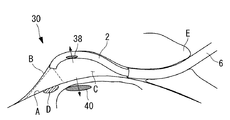
次に、本発明の第2の実施形態に係る内視鏡30について、図面を参照して以下に説明する。
本実施形態に係る内視鏡30の説明において、上述した第1の実施形態に係る内視鏡1と構成を共通とする箇所には同一符号を付して説明を省略する。
Next, an
In the description of the
本実施形態に係る内視鏡30は、図18および図19に示されるように、心臓Aの表面に吸着する吸着パッド7を備える固定手段3に代えて、心嚢膜Bに吸着する吸引口31を有する固定手段32を備えている。固定手段32を構成する各吸引口31は、図19に示されるように、挿入部2の側面に設けられていて、図示しない管路を介して負圧が供給されることにより、心嚢膜Bに挿入部2の側面を吸着させるようになっている。
As shown in FIGS. 18 and 19, the
吸引口31は、挿入部2の長手方向に間隔をあけて複数備えられ、それぞれが独立して負圧に吸引可能であることが好ましい。このようにすることで、負圧に吸引する吸引口31を切り替えて、挿入部2の心嚢膜Bへの吸着位置を調節することができる。
It is preferable that a plurality of
また、本実施形態においては、観察距離調節手段5として、挿入部2自体が、ガイドシース6から突出させられた状態で図18に示されるように湾曲するように癖づけられたものを採用している。
本実施形態に係る内視鏡30においては、挿入部2の先端面2bに前方の画像を取得する観察光学系4が設けられている。また、心臓A表面の患部を処置する処置具を出没させるように鉗子チャネル(図示略)も挿入部2の先端面2bに開口している。
Further, in the present embodiment, as the observation distance adjusting means 5, an
In the
このように構成された本実施形態に係る内視鏡30によれば、心膜腔C内にガイドシース6の先端を挿入した状態で、ガイドシース6内から内視鏡30の挿入部2を心膜腔C内に突出させることにより、挿入部2を湾曲させる。そして、挿入部2をその長手軸回りに回転させることにより、湾曲するように癖づけられた挿入部2によって心嚢膜Bと心臓A表面との間隔が広げられる。すなわち、心嚢膜Bと心臓A表面との間の心膜腔C内に観察のためのスペースが設けられるので、固定手段32によって心嚢膜Bに側面が吸着させられた挿入部2の先端面2bを心臓A表面から離れた位置で、心臓A表面に向けることができる。
According to the
拍動する心臓Aと対比して、心嚢膜Bは十分に静止していると考えることができ、該心嚢膜Bに吸着している挿入部2は、心臓Aの拍動に拘わらず、心嚢膜Bによって大きな変位を生じないように保持される。その結果、内視鏡30の観察光学系4の作動により、拍動している心臓Aの表面の比較的広い範囲にわたる鮮明な画像を取得することができる。すなわち、医師は、開胸手術によって患者の胸を切り開き、心嚢膜Bを切断して露出させた状態と同様の状態で心臓Aの表面を経内視鏡的に観察することができ、心臓Aの壊死部の観察や、病変部位に対する処置を容易にすることができる。
In contrast to the beating heart A, the pericardial membrane B can be considered to be sufficiently stationary, and the
なお、本実施形態においては、挿入部2の心嚢膜Bへの固定手段32として、挿入部2の側面に開口する1以上の吸引口31を有するものを採用したが、これに代えて、単一の吸引口31を有するものを採用してもよい。また、複数の吸引口31に同時に負圧を供給するものを採用してもよい。さらに、周方向に複数の吸引口31を有するものを採用してもよい。
In the present embodiment, as the
また、吸引口31を備える固定手段32に代えて、図20に示されるように、挿入部2の側面に出没可能に設けられ、挿入部2の側面から突出させられて、挿入部2の側面に近接して配置された心嚢膜Bを把持する把持部からなる固定手段33を採用してもよい。また、把持部からなる固定手段33に代えて、図21に示されるように、心嚢膜Bを穿刺する鉤からなる固定手段34を採用してもよい。
Further, instead of the fixing means 32 having the
また、吸引口31を備える固定手段32に代えて、図22に示されるように、挿入部2の側面に流体、例えば、空気を噴出する噴出口35を設け、該噴出口35から噴射される流体Fの勢いによって挿入部2を心嚢膜Bに押し付けて固定する固定手段36を採用してもよい。この場合に、単に噴出口35から流体Fを噴射するだけでは、心嚢膜B内に流体Fが充満してしまうので、供給した流体Fがガイドシース6を介して外部に排出されるように排出管37を心膜腔C内に開口させておけばよい。
Further, instead of the fixing means 32 having the
また、この場合に、心臓Aの表面に吹き付ける流体Fの勢いによって挿入部2を心嚢膜Bに押し付けるので、心臓Aが拍動した場合に挿入部2が拍動の影響を受けないように、心臓の拍動に同期させて噴出口35から噴出する空気の流量を調節することが好ましい。すなわち、心臓Aが膨張する時には空気流量を少なく、心臓Aが収縮する時には空気流量を多くするように調節することで、拍動の影響を最小限に抑制することができる。
In this case, since the
また、吸引口31を備える固定手段32に代えて、図23または図24に示されるように、挿入部2の側面に配置された磁石(磁力発生手段)38からなる固定手段を採用してもよい。図23に示される場合には、心嚢膜Bに磁石(磁力発生手段)39を固定しておき、該心嚢膜B側の磁石39と挿入部2側の磁石38との間の磁気吸引力によって挿入部2を心嚢膜Bに吸着させることができる。
Further, instead of the fixing means 32 having the
また、図24に示される場合には、心臓A内に磁石(磁力発生手段)40を固定しておき、該心臓A側の磁石40と挿入部2側の磁石38との間の磁気反発力によって、挿入部2を心嚢膜B側に押し付けて固定することができる。
この場合において、心臓A内に固定する磁石40または挿入部2側に設けた磁石38の少なくとも一方を電磁石によって構成し、電磁石により発生する磁力を調節することによって、磁気反発力を調節することができる。これにより、観察距離調節手段を構成することにしてもよい。
Further, in the case shown in FIG. 24, a magnet (magnetic force generating means) 40 is fixed in the heart A, and the magnetic repulsive force between the heart A
In this case, at least one of the
また、本実施形態においては、観察距離調節手段5として、湾曲した状態に癖づけた挿入部2自体を採用することとしたが、これに代えて、図25に示されるように、挿入部2と心臓A表面との間に配置されて膨張または収縮させられるバルーン41を採用してもよい。挿入部2を心嚢膜Bに吸着させた状態でバルーン41を膨張させることにより、心嚢膜Bと心臓A表面との間の心膜腔C内に観察用のスペースを形成することができる。また、バルーン41の膨張の程度を変更することにより、観察距離を調節することができる。また、バルーン41を心臓Aの表面に押し付けることにより、心臓Aの拍動を緩和して、観察光学系4により取得される画像のブレをさらに抑制することができる。
Further, in the present embodiment, the
また、上記各実施形態に係る内視鏡1,30においては、以下の変形を付与することにしてもよい。
第1に、バルーン5a,41は、挿入部2の長手方向に複数配列することとし、独立に膨張あるいは収縮可能に設けられていてもよい。
In the
First, a plurality of
例えば、図26に示されるように、剣状突起E下部から腹部を貫通して心尖H近傍の心膜腔C内に挿入されたガイドシース6から挿入部2を心膜腔C内に挿入していき、心膜翻転部Jにおいて略U字状に湾曲させて、先端面2bを心尖H側に向ける。この状態で、図27に示されるように、バルーン41を膨張させることにより、心臓Aの表面と心嚢膜Bとの間の心膜腔C内において、挿入部2の先端面2b周りに、斜線部Kの観察空間が確保されるとともに、図28に示されるように、挿入部2がバルーン41によって心嚢膜B側に押し付けられた状態に固定される。
For example, as shown in FIG. 26, the
さらに、この状態で挿入部2の先端の湾曲部2aを湾曲させることにより、バルーン41によって囲まれて、心嚢膜Bと心臓A表面との間に形成されたスペース内において、観察光学系4による広い視野範囲が確保され、詳細な観察を行うことができる。また、心拍のタイミングに合わせてバルーン41の拡張量を調節することにより、視野をより安定させることもできる。すなわち、心臓Aが拡張するときにはバルーン41の拡張量を小さく、心臓Aが収縮するときにはバルーン41の拡張量を大きく調節することにより、心嚢膜Bと心臓A表面との距離を一定に保持することができ、視野がより安定する。
なお、この場合に、図29に示されるように、膨張させるバルーン41を必要に応じて選択することにより必要最小限の観察用のスペースを確保することにしてもよい。
Furthermore, by bending the bending
In this case, as shown in FIG. 29, the necessary minimum observation space may be secured by selecting the
第2に、バルーン41に代えて、図30または図31に示されるように、ガイドシース6から挿入部2を突出させた時点で解放されて拡張するバネ42あるいは突っ張り棒43によって観察距離調節手段を構成してもよい。突っ張り棒43としては、図32に示されるように、突っ張り棒43が2カ所以上で心臓Aの表面に接触するように突出する構造のものが好ましい。このようにすることで、心臓Aの拍動に対して挿入部2が捻られないように安定化させることができる。
Second, in place of the
また、突っ張り棒43は、図33に示されるように、ガイドシース6から突出させることにしてもよい。
また、突っ張り棒を図16に示されるものと同様のリンク機構26によって構成し、突出量を調節することにしてもよい。
Further, the
Further, the tension rod may be constituted by a
また、図34に示されるように、ガイドシース6から挿入部2を突出させたときに拡張するように構成されたワイヤ44からなるバスケット44、あるいは図35に示されるような曲がり癖のある管状部材45あるいはワイヤ部材によって、心嚢膜Bと心臓A表面との間の心膜腔C内にスペースを設けることにしてもよい。
Further, as shown in FIG. 34, a
また、ガイドシース6から突出した挿入部2を心臓Aの拍動に対して安定させるために、図36に示されるように、挿入部2の両側面から半径方向に突出して心臓Aの表面に接触するワイヤ46からなるスタビライザを備えることにしてもよい。
また、ガイドシース6の開口部6a近傍において心臓A表面に挿入部2を吸着させる吸引口47を設けることにしてもよい。吸引口47は、図37に示されるように挿入部2の長手方向に間隔をあけて複数設けることにしてもよいし、図38に示されるように周方向に複数設けることにしてもよい。
Further, in order to stabilize the
Further, a
また、挿入部2自体を図39に示されるように、平坦に広がる構造のものを採用してもよい。図39(a)にはガイドシース6内を通過できるように細く纏まった状態、図39(b)には、ガイドシース6の開口部6aから突出した後に平坦に広がった状態の挿入部2がそれぞれ示されている。
また、図40に示されるように、平坦な断面形状を有する挿入部2を採用してもよい。
図中、符号48は照明光源である。
Further, as shown in FIG. 39, the
Further, as shown in FIG. 40, an
In the figure,
あるいは、図41に示されるように、断面円形の複数本の管状部材49を一列に並べて束ねた平坦な形態の挿入部2を採用してもよい。この場合、各管状部材49は、観察光学系4を有するものとチャネルの出口10を備えるものとにより構成することが好ましい。
Alternatively, as shown in FIG. 41, a flat-shaped
また、図42に示されるように、挿入部2の周方向に偏った位置の2カ所からバルーン50を膨張させることにしてもよい。このようにすることで、2カ所のバルーン50によって同時に心臓Aの表面を抑えるので、心臓の拍動を抑制しつつ、挿入部2を安定して支持することができる。
また、図43に示されるように、長円形断面形状に広がるバルーン51を採用することで、挿入部2を安定化させることにしてもよい。
Further, as shown in FIG. 42, the
Moreover, as shown in FIG. 43, the
A 心臓(組織)
1 内視鏡
2 挿入部
2a 湾曲部
3 固定手段
4 観察光学系
5 観察距離調節手段
5a バルーン
7 吸着パッド(吸着部)
7a 吸着面
7b 吸引孔
8 継手
8a 軸体(軸線)
10 出口
11 処置具
19 フック部材
21 バルーン部材
22 把持鉗子
23 蛇腹(管状部材)
24 弾性部材
25 ワイヤ
26 リンク機構
26a,26b リンク(リンク部材)
26d 関節部分
27 ガイドシース
A heart (tissue)
DESCRIPTION OF
DESCRIPTION OF
24
26d
Claims (19)
該挿入部の少なくとも先端部に設けられ、該挿入部を体内の組織に固定する固定手段と、
前記挿入部に設けられ、前記組織または該組織に隣接する隣接組織の画像を取得する観察光学系と、
該観察光学系と前記組織表面または前記隣接組織表面との距離を調節する観察距離調節手段とを備え、
前記固定手段が、負圧により前記組織を吸着する吸着部を有し、該吸着部の前記組織への吸着面が前記挿入部に対して角度変更可能に設けられている内視鏡。 An elongated insertion section that is inserted into the patient's body;
A fixing means provided at least at the distal end of the insertion portion, and fixing the insertion portion to a tissue in the body;
An observation optical system that is provided in the insertion portion and acquires an image of the tissue or an adjacent tissue adjacent to the tissue;
An observation distance adjusting means for adjusting a distance between the observation optical system and the tissue surface or the adjacent tissue surface;
An endoscope in which the fixing means includes an adsorption portion that adsorbs the tissue by negative pressure, and an adsorption surface of the adsorption portion to the tissue is provided so that an angle of the adsorption portion can be changed with respect to the insertion portion.
前記観察光学系が、いずれかの吸着部の間に設けられている請求項1又は請求項2に記載の内視鏡。 A plurality of the suction portions are provided at intervals in the longitudinal direction,
The endoscope according to claim 1, wherein the observation optical system is provided between any of the suction portions.
前記観察距離調節手段が、前記固定手段の間に配置され、前記挿入部を湾曲させる湾曲部により構成されている請求項1に記載の内視鏡。 A plurality of the fixing means are provided at intervals in the longitudinal direction of the insertion portion,
The endoscope according to claim 1, wherein the observation distance adjusting unit is configured by a bending portion that is disposed between the fixing units and bends the insertion portion.
前記チャネルの出口が、前記観察光学系と略同一の周方向に設けられている請求項14に記載の内視鏡。 The observation optical system is provided on a side surface of the insertion portion;
The endoscope according to claim 14 , wherein an outlet of the channel is provided in substantially the same circumferential direction as the observation optical system.
該挿入部の少なくとも先端部に設けられ、該挿入部を体内の組織に固定する固定手段と、
前記挿入部に設けられ、前記組織または該組織に隣接する隣接組織の画像を取得する観察光学系と、
該観察光学系と前記組織表面または前記隣接組織表面との距離を調節する観察距離調節手段とを備え、
前記固定手段が、磁力によって前記挿入部を前記組織に固定する磁力発生手段であり、
該観察距離調節手段が、前記磁力発生手段により発生する磁力を調節して、前記隣接組織内に配置した他の磁力発生手段との間の磁気反発力を調節する磁力調節手段を備える内視鏡。 An elongated insertion section that is inserted into the patient's body;
A fixing means provided at least at the distal end of the insertion portion, and fixing the insertion portion to a tissue in the body;
An observation optical system that is provided in the insertion portion and acquires an image of the tissue or an adjacent tissue adjacent to the tissue;
An observation distance adjusting means for adjusting a distance between the observation optical system and the tissue surface or the adjacent tissue surface;
The fixing means is a magnetic force generating means for fixing the insertion portion to the tissue by magnetic force;
An endoscope provided with the magnetic distance adjusting means for adjusting the magnetic repulsive force between the observation distance adjusting means and the other magnetic force generating means arranged in the adjacent tissue by adjusting the magnetic force generated by the magnetic force generating means. .
該挿入部の少なくとも先端部に設けられ、該挿入部を体内の組織に固定する固定手段と、
前記挿入部に設けられ、前記組織または該組織に隣接する隣接組織の画像を取得する観察光学系と、
該観察光学系と前記組織表面または前記隣接組織表面との距離を調節する観察距離調節手段とを備え、
前記固定手段が、流体の噴流によって前記挿入部を前記組織に固定する流体噴射手段である内視鏡。 An elongated insertion section that is inserted into the patient's body;
A fixing means provided at least at the distal end of the insertion portion, and fixing the insertion portion to a tissue in the body;
An observation optical system that is provided in the insertion portion and acquires an image of the tissue or an adjacent tissue adjacent to the tissue;
An observation distance adjusting means for adjusting a distance between the observation optical system and the tissue surface or the adjacent tissue surface;
An endoscope in which the fixing means is a fluid ejecting means for fixing the insertion portion to the tissue by a jet of fluid.
The endoscope according to claim 18 , wherein the observation distance adjusting unit is a flow rate adjusting unit that adjusts a flow rate of a fluid ejected by the fluid ejecting unit.
Priority Applications (7)
| Application Number | Priority Date | Filing Date | Title |
|---|---|---|---|
| JP2009285073A JP5415925B2 (en) | 2009-03-02 | 2009-12-16 | Endoscope |
| US12/714,827 US8900123B2 (en) | 2009-03-02 | 2010-03-01 | Endoscopy method and endoscope |
| US12/757,210 US8747297B2 (en) | 2009-03-02 | 2010-04-09 | Endoscopic heart surgery method |
| CN201080052838.5A CN102665528B (en) | 2009-09-22 | 2010-08-30 | Endoscope |
| US12/871,172 US20100331619A1 (en) | 2009-03-02 | 2010-08-30 | Endoscopic heart surgery method |
| EP10818652.9A EP2481336B1 (en) | 2009-09-22 | 2010-08-30 | Endoscope |
| PCT/JP2010/064674 WO2011036976A1 (en) | 2009-03-02 | 2010-08-30 | Endoscope |
Applications Claiming Priority (5)
| Application Number | Priority Date | Filing Date | Title |
|---|---|---|---|
| JP2009048460 | 2009-03-02 | ||
| JP2009048460 | 2009-03-02 | ||
| US24458609P | 2009-09-22 | 2009-09-22 | |
| US61/244,586 | 2009-09-22 | ||
| JP2009285073A JP5415925B2 (en) | 2009-03-02 | 2009-12-16 | Endoscope |
Publications (3)
| Publication Number | Publication Date |
|---|---|
| JP2010284503A JP2010284503A (en) | 2010-12-24 |
| JP2010284503A5 JP2010284503A5 (en) | 2011-04-21 |
| JP5415925B2 true JP5415925B2 (en) | 2014-02-12 |
Family
ID=43540668
Family Applications (1)
| Application Number | Title | Priority Date | Filing Date |
|---|---|---|---|
| JP2009285073A Expired - Fee Related JP5415925B2 (en) | 2009-03-02 | 2009-12-16 | Endoscope |
Country Status (3)
| Country | Link |
|---|---|
| US (1) | US8900123B2 (en) |
| JP (1) | JP5415925B2 (en) |
| WO (1) | WO2011036976A1 (en) |
Families Citing this family (27)
| Publication number | Priority date | Publication date | Assignee | Title |
|---|---|---|---|---|
| EP2579785B1 (en) | 2010-06-14 | 2016-11-16 | Maquet Cardiovascular LLC | Surgical instruments, systems and methods of use |
| US9393001B2 (en) * | 2011-07-29 | 2016-07-19 | Olympus Corporation | Operation method of endoscope |
| JP2013103075A (en) * | 2011-11-16 | 2013-05-30 | Olympus Corp | Guidance medical system |
| JP6199011B2 (en) * | 2012-06-11 | 2017-09-20 | Hoya株式会社 | Ultrasound endoscope |
| US9402531B2 (en) * | 2012-07-05 | 2016-08-02 | Pavilion Medical Innovations, Llc | Endoscopic cannulas and methods of using the same |
| AT513922A1 (en) * | 2013-02-07 | 2014-08-15 | Michael Dr Goritschan | endoscope |
| JP6185294B2 (en) * | 2013-06-11 | 2017-08-23 | オリンパス株式会社 | Endoscope |
| US9320539B2 (en) | 2013-09-30 | 2016-04-26 | Coloplast A/S | Surgical system for and a method of dissection of tissue away from an organ or body lumen |
| US9717443B2 (en) * | 2014-06-12 | 2017-08-01 | Coloplast A/S | Surgical tool and method for identifying an incision site |
| US9717578B2 (en) | 2014-06-12 | 2017-08-01 | Coloplast A/S | Surgical tool adapted for identifying an incision site |
| DE112014006902T5 (en) * | 2014-10-09 | 2017-05-24 | Olympus Corporation | Medical system |
| DE112014007012T5 (en) * | 2014-11-18 | 2017-06-22 | Olympus Corporation | Medical instrument |
| JP5945586B2 (en) * | 2014-12-08 | 2016-07-05 | オリンパス株式会社 | Medical device guide system |
| JP6571183B2 (en) * | 2015-06-18 | 2019-09-04 | オリンパス株式会社 | Pericardial endoscope system |
| WO2017090196A1 (en) * | 2015-11-27 | 2017-06-01 | オリンパス株式会社 | Endoscope adapter, endoscope, and endoscope system |
| US10582835B2 (en) | 2016-03-01 | 2020-03-10 | Cook Medical Technologies Llc | Flexible endoscopic support system |
| EP3422922B1 (en) * | 2016-03-01 | 2022-10-19 | Cook Medical Technologies LLC | Deflecting endoscope accessory channels |
| WO2017203582A1 (en) | 2016-05-23 | 2017-11-30 | オリンパス株式会社 | Endoscope-use device, and endoscopic system |
| JPWO2018100605A1 (en) * | 2016-11-29 | 2019-06-27 | オリンパス株式会社 | Endoscope system |
| WO2018109893A1 (en) * | 2016-12-15 | 2018-06-21 | オリンパス株式会社 | Endoscope and endoscope system |
| WO2018229982A1 (en) * | 2017-06-16 | 2018-12-20 | オリンパス株式会社 | Endoscope sheath and endoscope system |
| JP6391783B2 (en) * | 2017-07-27 | 2018-09-19 | オリンパス株式会社 | Endoscope |
| WO2019087254A1 (en) * | 2017-10-30 | 2019-05-09 | オリンパス株式会社 | Endoscope system |
| US10750936B2 (en) * | 2017-11-02 | 2020-08-25 | Olympus Corporation | Pericardial-cavity observing method |
| CN112020333B (en) * | 2018-04-26 | 2024-06-25 | 奥林巴斯株式会社 | Disposal Systems and Expansion Devices |
| JP7631336B2 (en) * | 2019-11-18 | 2025-02-18 | サーカ サイエンティフィック インコーポレイテッド | Epicardial Ablation Instrument Port with Anatomical Epicardial Structures and Real-Time Lesion Image Processor |
| US11136879B2 (en) | 2020-01-31 | 2021-10-05 | Aver Technologies, Inc. | Borescope for drilled shaft inspection |
Family Cites Families (123)
| Publication number | Priority date | Publication date | Assignee | Title |
|---|---|---|---|---|
| US3281141A (en) | 1963-01-15 | 1966-10-25 | American Sterilizer Co | Surgical table |
| US3859985A (en) | 1973-06-27 | 1975-01-14 | Becton Dickinson Co | Angiography valve |
| US4063553A (en) | 1976-04-08 | 1977-12-20 | Bell & Howell Company | Pressure transducing methods and apparatus |
| US4224929A (en) * | 1977-11-08 | 1980-09-30 | Olympus Optical Co., Ltd. | Endoscope with expansible cuff member and operation section |
| US4319568A (en) | 1979-10-29 | 1982-03-16 | Vickers Limited | Liquid dispensing apparatus |
| GB8424101D0 (en) | 1984-09-24 | 1984-10-31 | Vi Tal Hospital Products Ltd | Air-in-line detector |
| JPS6235318A (en) * | 1985-08-09 | 1987-02-16 | Canon Inc | Endoscope operating method |
| JP2575395B2 (en) * | 1987-07-15 | 1997-01-22 | オリンパス光学工業株式会社 | Antenna device for NMR measurement |
| US5035231A (en) | 1987-04-27 | 1991-07-30 | Olympus Optical Co., Ltd. | Endoscope apparatus |
| US4884567A (en) | 1987-12-03 | 1989-12-05 | Dimed Inc. | Method for transvenous implantation of objects into the pericardial space of patients |
| JPH0255960A (en) | 1988-08-20 | 1990-02-26 | Fujikura Ltd | Photoelectric current sensor |
| US4991603A (en) | 1989-10-30 | 1991-02-12 | Siemens-Pacesetter, Inc. | Transvenously placed defibrillation leads via an inferior vena cava access site and method of use |
| US5048537A (en) | 1990-05-15 | 1991-09-17 | Medex, Inc. | Method and apparatus for sampling blood |
| US5361752A (en) | 1991-05-29 | 1994-11-08 | Origin Medsystems, Inc. | Retraction apparatus and methods for endoscopic surgery |
| US5370134A (en) | 1991-05-29 | 1994-12-06 | Orgin Medsystems, Inc. | Method and apparatus for body structure manipulation and dissection |
| US5795325A (en) | 1991-07-16 | 1998-08-18 | Heartport, Inc. | Methods and apparatus for anchoring an occluding member |
| JPH07501959A (en) | 1991-11-19 | 1995-03-02 | オリジン・メドシステムズ・インク | Endoscopic inflatable retraction device and method of use for separating tissue layers |
| US5336252A (en) | 1992-06-22 | 1994-08-09 | Cohen Donald M | System and method for implanting cardiac electrical leads |
| US5297536A (en) | 1992-08-25 | 1994-03-29 | Wilk Peter J | Method for use in intra-abdominal surgery |
| US5324266A (en) | 1992-12-23 | 1994-06-28 | Abbott Laboratories | In-line sampling system incorporating an improved blood sampling device |
| US5400773A (en) * | 1993-01-19 | 1995-03-28 | Loma Linda University Medical Center | Inflatable endoscopic retractor |
| US6478029B1 (en) | 1993-02-22 | 2002-11-12 | Hearport, Inc. | Devices and methods for port-access multivessel coronary artery bypass surgery |
| US5725525A (en) | 1993-03-16 | 1998-03-10 | Ep Technologies, Inc. | Multiple electrode support structures with integral hub and spline elements |
| SE9303253D0 (en) | 1993-10-05 | 1993-10-05 | Siemens Elema Ab | Instruments for peephole surgery |
| US5522804A (en) | 1994-02-15 | 1996-06-04 | Lynn; Lawrence A. | Aspiration, mixing, and injection syringe |
| JPH08117232A (en) | 1994-10-24 | 1996-05-14 | Olympus Optical Co Ltd | Biopsy needle |
| JPH08280815A (en) | 1995-04-19 | 1996-10-29 | Sumitomo Bakelite Co Ltd | Catheter for stent delivery |
| US5827216A (en) | 1995-06-07 | 1998-10-27 | Cormedics Corp. | Method and apparatus for accessing the pericardial space |
| JP3053566B2 (en) | 1995-07-07 | 2000-06-19 | オリンパス光学工業株式会社 | Cavity securing tool |
| US5759150A (en) | 1995-07-07 | 1998-06-02 | Olympus Optical Co., Ltd. | System for evulsing subcutaneous tissue |
| US5836311A (en) | 1995-09-20 | 1998-11-17 | Medtronic, Inc. | Method and apparatus for temporarily immobilizing a local area of tissue |
| US5697916A (en) | 1995-11-21 | 1997-12-16 | Stat Medical Devices Inc. | Hypodermic dosage measuring device |
| US5894843A (en) | 1996-02-20 | 1999-04-20 | Cardiothoracic Systems, Inc. | Surgical method for stabilizing the beating heart during coronary artery bypass graft surgery |
| CA2197614C (en) | 1996-02-20 | 2002-07-02 | Charles S. Taylor | Surgical instruments and procedures for stabilizing the beating heart during coronary artery bypass graft surgery |
| ES2128936B1 (en) | 1996-05-22 | 2000-01-16 | Patentes Novedades Sa | PROCEDURE FOR OBTAINING PENTAERITRITOL. |
| US6059750A (en) | 1996-08-01 | 2000-05-09 | Thomas J. Fogarty | Minimally invasive direct cardiac massage device and method |
| JP3017451B2 (en) | 1996-11-11 | 2000-03-06 | オリンパス光学工業株式会社 | Hood for endoscope |
| US5931810A (en) | 1996-12-05 | 1999-08-03 | Comedicus Incorporated | Method for accessing the pericardial space |
| US5735791A (en) | 1997-01-31 | 1998-04-07 | Research Medical, Inc. | Inflatable heart elevation apparatus and method |
| JP3036686B2 (en) | 1997-02-27 | 2000-04-24 | 政夫 高橋 | Hemostatic holding device for vascular anastomosis used for coronary artery bypass surgery |
| US6390976B1 (en) | 1997-09-17 | 2002-05-21 | Origin Medsystems, Inc. | System to permit offpump beating heart coronary bypass surgery |
| US6592552B1 (en) | 1997-09-19 | 2003-07-15 | Cecil C. Schmidt | Direct pericardial access device and method |
| US5968017A (en) | 1997-10-14 | 1999-10-19 | Merit Medical Systems, Inc. | Pulse fluid infusion systems |
| US6015382A (en) | 1997-10-16 | 2000-01-18 | General Surgical Innovations, Inc. | Inflatable manipulator for organ positioning during surgery and method of use |
| US6017332A (en) | 1997-10-20 | 2000-01-25 | Urrutia; Hector | Medical dye delivery system |
| JPH11276422A (en) | 1998-03-31 | 1999-10-12 | Fuji Photo Optical Co Ltd | Ultrasonic endoscope |
| US6267717B1 (en) | 1998-03-31 | 2001-07-31 | Advanced Research & Technology Institute | Apparatus and method for treating a body structure with radiation |
| US6740082B2 (en) | 1998-12-29 | 2004-05-25 | John H. Shadduck | Surgical instruments for treating gastro-esophageal reflux |
| CA2333149A1 (en) | 1998-05-26 | 1999-12-02 | Comedicus Incorporated | Intrapericardial procedures and apparatuses |
| CZ164098A3 (en) | 1998-05-28 | 2000-02-16 | Milan Mudr. Csc. Krajíček | Stabilizer of heart muscle |
| US6309374B1 (en) | 1998-08-03 | 2001-10-30 | Insite Vision Incorporated | Injection apparatus and method of using same |
| JP2000176011A (en) | 1998-12-18 | 2000-06-27 | Urrutia Hector | Medical pigment transmitting system |
| JP4180799B2 (en) | 1999-04-16 | 2008-11-12 | メディヴァス,エルエルシー. | Treatment site stabilization device and method of use thereof |
| US7398781B1 (en) | 1999-08-10 | 2008-07-15 | Maquet Cardiovascular, Llc | Method for subxiphoid endoscopic access |
| US6977080B1 (en) | 1999-08-10 | 2005-12-20 | Allergan, Inc. | Intrapericardial botulinum toxin treatment for bradycardia |
| US7526342B2 (en) * | 1999-08-10 | 2009-04-28 | Maquet Cardiovascular Llc | Apparatus for endoscopic cardiac mapping and lead placement |
| US6517477B1 (en) | 2000-01-27 | 2003-02-11 | Scimed Life Systems, Inc. | Catheter introducer system for exploration of body cavities |
| CN1243574C (en) | 2000-04-12 | 2006-03-01 | 舍伍德服务公开股份有限公司 | Thoracentesis instrument with highly sensitive detection mechanism |
| US6471644B1 (en) * | 2000-04-27 | 2002-10-29 | Medtronic, Inc. | Endoscopic stabilization device and method of use |
| JP4517321B2 (en) | 2000-06-05 | 2010-08-04 | 有限会社エスアールジェイ | Overtube |
| JP2002017854A (en) | 2000-07-11 | 2002-01-22 | Daiken Iki Kk | Flow controller for chemical injection device |
| US6666861B1 (en) | 2000-10-05 | 2003-12-23 | James R. Grabek | Atrial appendage remodeling device and method |
| US6890295B2 (en) | 2002-10-31 | 2005-05-10 | Medtronic, Inc. | Anatomical space access tools and methods |
| US6786898B2 (en) | 2003-01-15 | 2004-09-07 | Medtronic, Inc. | Methods and tools for accessing an anatomic space |
| US6706013B1 (en) | 2001-06-29 | 2004-03-16 | Advanced Cardiovascular Systems, Inc. | Variable length drug delivery catheter |
| JP4768154B2 (en) * | 2001-06-29 | 2011-09-07 | テルモ株式会社 | Medical energy irradiation device |
| WO2003039354A1 (en) | 2001-10-18 | 2003-05-15 | Atropos Limited | A device to aid advancement of a colonoscope |
| JP3859491B2 (en) * | 2001-11-15 | 2006-12-20 | オリンパス株式会社 | Endoscope sheath |
| JP2004033525A (en) | 2002-07-04 | 2004-02-05 | Fuji Photo Optical Co Ltd | Hardness variable treatment instrument |
| US7376456B2 (en) | 2002-08-05 | 2008-05-20 | Infraredx, Inc. | Near-infrared spectroscopic analysis of blood vessel walls |
| JP4385118B2 (en) | 2002-08-07 | 2009-12-16 | 独立行政法人産業技術総合研究所 | Needle-piercing device and method for detecting the operating state of the needle of the needle-piercing device |
| JP4334838B2 (en) * | 2002-09-06 | 2009-09-30 | オリンパス株式会社 | Endoscope device |
| JP4088918B2 (en) | 2002-09-13 | 2008-05-21 | 東レ・メディカル株式会社 | Hemodialysis machine |
| BR0317569B1 (en) * | 2003-01-21 | 2013-06-04 | disposable device for surgical operations on the haemorroidalis artery. | |
| US7394976B2 (en) | 2003-03-25 | 2008-07-01 | Arizant Healthcare Inc. | Fluid warming cassette and system capable of operation under negative pressure |
| JP4274073B2 (en) | 2003-08-08 | 2009-06-03 | 住友ベークライト株式会社 | Coronary artery bypass surgery instrument |
| CA2439667A1 (en) | 2003-09-04 | 2005-03-04 | Andrew Kenneth Hoffmann | Low frequency vibration assisted blood perfusion system and apparatus |
| US7341558B2 (en) | 2003-09-19 | 2008-03-11 | Medcanica, Llc | Pericardial retractor |
| US20070023334A1 (en) | 2003-09-23 | 2007-02-01 | Gambro Lundia Ab | Apparatus, a system and a method relating to hemodialysis, hemodiafiltration, hemofiltration or peritoneal dialysis |
| US20050159645A1 (en) | 2003-11-12 | 2005-07-21 | Bertolero Arthur A. | Balloon catheter sheath |
| JP2005169009A (en) | 2003-12-15 | 2005-06-30 | Olympus Corp | Endoscope system and endoscope |
| US7399272B2 (en) | 2004-03-24 | 2008-07-15 | Medtronic, Inc. | Methods and apparatus providing suction-assisted tissue engagement |
| WO2005110194A1 (en) | 2004-05-14 | 2005-11-24 | Olympus Corporation | Insertion device |
| US8926635B2 (en) * | 2004-06-18 | 2015-01-06 | Medtronic, Inc. | Methods and devices for occlusion of an atrial appendage |
| US7229408B2 (en) | 2004-06-30 | 2007-06-12 | Ethicon, Inc. | Low profile surgical retractor |
| ITBO20040443A1 (en) | 2004-07-16 | 2004-10-16 | Cefla Coop | ORAL CABLE RETRACTOR |
| CA2589523C (en) | 2004-12-02 | 2016-01-05 | Bradley H. Strauss | Augmentation of intraluminal microvessel formation to facilitate guide wire crossing in chronic total occlusions |
| US20080015569A1 (en) * | 2005-02-02 | 2008-01-17 | Voyage Medical, Inc. | Methods and apparatus for treatment of atrial fibrillation |
| JP2006271831A (en) | 2005-03-30 | 2006-10-12 | Terumo Corp | Medical treatment device and its usage |
| US20060259017A1 (en) * | 2005-04-27 | 2006-11-16 | Cardiac Pacemakers, Inc. | Adhesive elements and methods for accessing the pericardial space |
| CN101175517A (en) | 2005-05-16 | 2008-05-07 | 马林克罗特公司 | Multi-barrel syringe with integrated tubing |
| US20070088203A1 (en) | 2005-05-25 | 2007-04-19 | Liming Lau | Surgical assemblies and methods for visualizing and performing surgical procedures in reduced-access surgical sites |
| US7837688B2 (en) | 2005-06-13 | 2010-11-23 | Globus Medical | Spinous process spacer |
| JP2007029556A (en) * | 2005-07-28 | 2007-02-08 | Olympus Corp | Insertion assisting appliance for medical apparatus |
| JP2007054333A (en) * | 2005-08-25 | 2007-03-08 | Pentax Corp | OCT probe and OCT system |
| WO2007052354A1 (en) * | 2005-11-04 | 2007-05-10 | Olympus Medical Systems Corp. | Endoscope system, endoscope, supporting member and method of using endoscope system |
| US20070135686A1 (en) | 2005-12-14 | 2007-06-14 | Pruitt John C Jr | Tools and methods for epicardial access |
| EP1968466A2 (en) | 2005-12-19 | 2008-09-17 | M. S. Abdou | Devices for inter-vertebral orthopedic device placement |
| EP1980194B1 (en) | 2006-01-06 | 2013-05-08 | Olympus Medical Systems Corp. | Trans-natural opening based or transcutaneous medical system |
| JP5116985B2 (en) * | 2006-04-13 | 2013-01-09 | 富士フイルム株式会社 | Endoscope |
| US8342183B2 (en) * | 2006-04-19 | 2013-01-01 | Vibrynt, Inc. | Devices and methods for treatment of obesity |
| CN102697444B (en) * | 2006-05-18 | 2015-05-20 | 智能医疗系统有限公司 | Flexible endoscope system and functionality |
| US20070270882A1 (en) | 2006-05-19 | 2007-11-22 | Acorn Cardiovascular, Inc. | Pericardium management method for intra-pericardial surgical procedures |
| US8092470B2 (en) * | 2006-06-08 | 2012-01-10 | Olympus Medical Systems Corp. | Calculus crushing apparatus and medical procedure using endoscope |
| WO2008111070A2 (en) * | 2007-03-12 | 2008-09-18 | David Tolkowsky | Devices and methods for performing medical procedures in tree-like luminal structures |
| JP2008259701A (en) | 2007-04-12 | 2008-10-30 | Olympus Corp | Apparatus inserted into living body |
| FR2914840A1 (en) | 2007-04-16 | 2008-10-17 | Lk2 Soc Responsabilite Limitee | Connection for blood sampling device, has sampling valve sampling fluid sample contained in sampling path, where path has Luer lock type syringe that drives part of fluid contained in sampling path towards catheter path |
| US9155452B2 (en) * | 2007-04-27 | 2015-10-13 | Intuitive Surgical Operations, Inc. | Complex shape steerable tissue visualization and manipulation catheter |
| JP2008284108A (en) | 2007-05-16 | 2008-11-27 | Olympus Corp | Stabilizer |
| US8109903B2 (en) * | 2007-05-21 | 2012-02-07 | Smart Medical Systems Ltd. | Catheter including a bendable portion |
| CN101687069B (en) | 2007-06-29 | 2013-01-16 | 株式会社Jms | Hemodialyzer |
| JP5011024B2 (en) * | 2007-08-10 | 2012-08-29 | オリンパスメディカルシステムズ株式会社 | Endoscope |
| US8311620B2 (en) | 2007-08-22 | 2012-11-13 | Cardiac Pacemakers, Inc. | Methods and apparatus to treat and prevent atrial tachyarrhythmias |
| JP2011510786A (en) | 2008-02-05 | 2011-04-07 | シーヴィ デヴァイシズ,エルエルシー | Steering engagement catheter apparatus, system and method |
| EP2303136A1 (en) * | 2008-04-21 | 2011-04-06 | Medtronic, Inc. | Suction force ablation device |
| JP3143693U (en) * | 2008-05-22 | 2008-07-31 | 財団法人ヒューマンサイエンス振興財団 | Endoscope device and endoscope hood |
| US8690762B2 (en) | 2008-06-18 | 2014-04-08 | Raytheon Company | Transparent endoscope head defining a focal length |
| EP2349033B1 (en) | 2008-10-10 | 2020-04-08 | Surgiquest, Inc. | Low-profile surgical access devices with anchoring |
| JP2010142422A (en) * | 2008-12-18 | 2010-07-01 | Fujifilm Corp | Optical probe and optical observation apparatus |
| EP2378990B1 (en) | 2008-12-22 | 2018-05-16 | Synthes GmbH | Expandable interspinous process spacer |
| US20100268029A1 (en) | 2009-04-21 | 2010-10-21 | Xlumena, Inc. | Methods and apparatus for advancing a device from one body lumen to another |
| US20100317925A1 (en) * | 2009-06-12 | 2010-12-16 | Banchieri Michael J | Suction-assisted tissue stabilizers |
| WO2011041638A2 (en) * | 2009-10-02 | 2011-04-07 | Cardiofocus, Inc. | Cardiac ablation system with automatic safety shut-off feature |
-
2009
- 2009-12-16 JP JP2009285073A patent/JP5415925B2/en not_active Expired - Fee Related
-
2010
- 2010-03-01 US US12/714,827 patent/US8900123B2/en active Active
- 2010-08-30 WO PCT/JP2010/064674 patent/WO2011036976A1/en not_active Ceased
Also Published As
| Publication number | Publication date |
|---|---|
| WO2011036976A1 (en) | 2011-03-31 |
| US8900123B2 (en) | 2014-12-02 |
| JP2010284503A (en) | 2010-12-24 |
| US20100240952A1 (en) | 2010-09-23 |
Similar Documents
| Publication | Publication Date | Title |
|---|---|---|
| JP5415925B2 (en) | Endoscope | |
| CN102665528B (en) | Endoscope | |
| JP5173930B2 (en) | Surgical device | |
| JP7660583B2 (en) | Medical Therapeutic System and Method of Using Same | |
| JP5089959B2 (en) | Lumen Traverse Tool | |
| JP6273298B2 (en) | Operable medical device | |
| JP4994849B2 (en) | Endoscope assembly | |
| JP4885640B2 (en) | Endoscope insertion aid | |
| JP5568629B2 (en) | Device for moving an endoscope forward in a pipeline | |
| US8636651B2 (en) | Medical immobilization device and related methods of use | |
| JP2018506350A (en) | System for minimally invasive gastrointestinal surgery | |
| JP2009504229A (en) | Balloon guided endoscopy | |
| JP2009050559A (en) | Endoscope insertion device | |
| JP7564340B2 (en) | STABILIZATION AND LEVERAGE DEVICES, SYSTEMS, AND METHODS | |
| US10292572B2 (en) | Bending device, control device, and medical instrument | |
| EP2934344A2 (en) | An inflatable laparoscopic retractor for atraumatic retraction in abdominal surgery | |
| JP2010213800A (en) | Catheter | |
| JP3888359B2 (en) | Endoscope device | |
| CN105902313A (en) | Balloon type separable dobby soft robot | |
| JP5580540B2 (en) | Guide device | |
| JP5100263B2 (en) | Treatment instrument guide | |
| US20260034293A1 (en) | Endoluminal treatment systems, devices, and related methods | |
| WO2019087254A1 (en) | Endoscope system | |
| WO2026030267A1 (en) | Endoluminal treatment devices | |
| JP2000102542A (en) | Ligating instrument for endoscope |
Legal Events
| Date | Code | Title | Description |
|---|---|---|---|
| A521 | Request for written amendment filed |
Free format text: JAPANESE INTERMEDIATE CODE: A523 Effective date: 20110304 |
|
| A621 | Written request for application examination |
Free format text: JAPANESE INTERMEDIATE CODE: A621 Effective date: 20110304 |
|
| A131 | Notification of reasons for refusal |
Free format text: JAPANESE INTERMEDIATE CODE: A131 Effective date: 20120717 |
|
| A521 | Request for written amendment filed |
Free format text: JAPANESE INTERMEDIATE CODE: A523 Effective date: 20120913 |
|
| A131 | Notification of reasons for refusal |
Free format text: JAPANESE INTERMEDIATE CODE: A131 Effective date: 20130305 |
|
| A521 | Request for written amendment filed |
Free format text: JAPANESE INTERMEDIATE CODE: A523 Effective date: 20130502 |
|
| TRDD | Decision of grant or rejection written | ||
| A01 | Written decision to grant a patent or to grant a registration (utility model) |
Free format text: JAPANESE INTERMEDIATE CODE: A01 Effective date: 20131029 |
|
| A61 | First payment of annual fees (during grant procedure) |
Free format text: JAPANESE INTERMEDIATE CODE: A61 Effective date: 20131114 |
|
| R151 | Written notification of patent or utility model registration |
Ref document number: 5415925 Country of ref document: JP Free format text: JAPANESE INTERMEDIATE CODE: R151 |
|
| S531 | Written request for registration of change of domicile |
Free format text: JAPANESE INTERMEDIATE CODE: R313531 |
|
| R350 | Written notification of registration of transfer |
Free format text: JAPANESE INTERMEDIATE CODE: R350 |
|
| R250 | Receipt of annual fees |
Free format text: JAPANESE INTERMEDIATE CODE: R250 |
|
| LAPS | Cancellation because of no payment of annual fees |