JP5408453B2 - Lid for containers with safety function under internal pressure and closing lid for fuel tank - Google Patents
Lid for containers with safety function under internal pressure and closing lid for fuel tank Download PDFInfo
- Publication number
- JP5408453B2 JP5408453B2 JP2010526243A JP2010526243A JP5408453B2 JP 5408453 B2 JP5408453 B2 JP 5408453B2 JP 2010526243 A JP2010526243 A JP 2010526243A JP 2010526243 A JP2010526243 A JP 2010526243A JP 5408453 B2 JP5408453 B2 JP 5408453B2
- Authority
- JP
- Japan
- Prior art keywords
- lid
- lid body
- membrane
- engagement ring
- relief valve
- Prior art date
- Legal status (The legal status is an assumption and is not a legal conclusion. Google has not performed a legal analysis and makes no representation as to the accuracy of the status listed.)
- Expired - Fee Related
Links
- 239000002828 fuel tank Substances 0.000 title 1
- 239000012528 membrane Substances 0.000 claims description 24
- 230000006835 compression Effects 0.000 claims description 10
- 238000007906 compression Methods 0.000 claims description 10
- 239000000446 fuel Substances 0.000 claims description 9
- 230000008878 coupling Effects 0.000 description 9
- 238000010168 coupling process Methods 0.000 description 9
- 238000005859 coupling reaction Methods 0.000 description 9
- 238000005192 partition Methods 0.000 description 2
- 238000007789 sealing Methods 0.000 description 2
- 230000001419 dependent effect Effects 0.000 description 1
- 238000011161 development Methods 0.000 description 1
- 230000018109 developmental process Effects 0.000 description 1
- 230000009977 dual effect Effects 0.000 description 1
Images


Classifications
-
- B—PERFORMING OPERATIONS; TRANSPORTING
- B60—VEHICLES IN GENERAL
- B60K—ARRANGEMENT OR MOUNTING OF PROPULSION UNITS OR OF TRANSMISSIONS IN VEHICLES; ARRANGEMENT OR MOUNTING OF PLURAL DIVERSE PRIME-MOVERS IN VEHICLES; AUXILIARY DRIVES FOR VEHICLES; INSTRUMENTATION OR DASHBOARDS FOR VEHICLES; ARRANGEMENTS IN CONNECTION WITH COOLING, AIR INTAKE, GAS EXHAUST OR FUEL SUPPLY OF PROPULSION UNITS IN VEHICLES
- B60K15/00—Arrangement in connection with fuel supply of combustion engines or other fuel consuming energy converters, e.g. fuel cells; Mounting or construction of fuel tanks
- B60K15/03—Fuel tanks
- B60K15/04—Tank inlets
- B60K15/0406—Filler caps for fuel tanks
-
- B—PERFORMING OPERATIONS; TRANSPORTING
- B60—VEHICLES IN GENERAL
- B60K—ARRANGEMENT OR MOUNTING OF PROPULSION UNITS OR OF TRANSMISSIONS IN VEHICLES; ARRANGEMENT OR MOUNTING OF PLURAL DIVERSE PRIME-MOVERS IN VEHICLES; AUXILIARY DRIVES FOR VEHICLES; INSTRUMENTATION OR DASHBOARDS FOR VEHICLES; ARRANGEMENTS IN CONNECTION WITH COOLING, AIR INTAKE, GAS EXHAUST OR FUEL SUPPLY OF PROPULSION UNITS IN VEHICLES
- B60K15/00—Arrangement in connection with fuel supply of combustion engines or other fuel consuming energy converters, e.g. fuel cells; Mounting or construction of fuel tanks
- B60K15/03—Fuel tanks
- B60K15/035—Fuel tanks characterised by venting means
- B60K2015/03542—Mounting of the venting means
- B60K2015/03547—Mounting of the venting means the venting means are integrated in the fuel cap or inlet cover
-
- B—PERFORMING OPERATIONS; TRANSPORTING
- B60—VEHICLES IN GENERAL
- B60K—ARRANGEMENT OR MOUNTING OF PROPULSION UNITS OR OF TRANSMISSIONS IN VEHICLES; ARRANGEMENT OR MOUNTING OF PLURAL DIVERSE PRIME-MOVERS IN VEHICLES; AUXILIARY DRIVES FOR VEHICLES; INSTRUMENTATION OR DASHBOARDS FOR VEHICLES; ARRANGEMENTS IN CONNECTION WITH COOLING, AIR INTAKE, GAS EXHAUST OR FUEL SUPPLY OF PROPULSION UNITS IN VEHICLES
- B60K15/00—Arrangement in connection with fuel supply of combustion engines or other fuel consuming energy converters, e.g. fuel cells; Mounting or construction of fuel tanks
- B60K15/03—Fuel tanks
- B60K15/04—Tank inlets
- B60K15/0406—Filler caps for fuel tanks
- B60K2015/0451—Sealing means in the closure cap
Landscapes
- Engineering & Computer Science (AREA)
- Life Sciences & Earth Sciences (AREA)
- Sustainable Development (AREA)
- Sustainable Energy (AREA)
- Chemical & Material Sciences (AREA)
- Combustion & Propulsion (AREA)
- Transportation (AREA)
- Mechanical Engineering (AREA)
- Cooling, Air Intake And Gas Exhaust, And Fuel Tank Arrangements In Propulsion Units (AREA)
- Closures For Containers (AREA)
Description
本発明は、内圧を受ける容器用の閉鎖蓋であって、回転により容器の受け口に固定可能な蓋本体と、取っ手を備えかつ蓋本体に結合可能な蓋とを有するものに関する。本発明は、特に僅かな正圧を受ける自動車の燃料容器にも関する。 The present invention relates to a closed lid for a container that receives an internal pressure, the lid having a lid body that can be fixed to a receptacle port by rotation, and a lid that has a handle and can be coupled to the lid body. The invention also relates to a fuel container for an automobile, in particular subject to a slight positive pressure.
米国特許出願公開第2001/0047995号明細書は、自動車の燃料容器の充填受け口を蒸気漏れのないように閉鎖するタンク蓋を記載している。それにもかかわらず、新しいタンク蓋には逃がし弁が設けられて、確実に漏れなく閉鎖せねばならず、極めてまれにしか開かない。 U.S. Patent Application Publication No. 2001/0047995 describes a tank lid that closes a filling receptacle of a fuel container of an automobile to prevent vapor leakage. Nevertheless, the new tank lid is provided with a relief valve that must be securely closed without leaking and opens very rarely.
最近機関側の理由から、タンクの内部に僅かな正圧を維持することが考慮される。燃料蒸気が逃げるのを防止するため正常作動のために僅かな正圧がタンク内に存在し、従って圧力が第1の閾値以上である間は、タンクを開いてはならない。正常作動中に良好な密封に注意せねばならない。このことは、一層高い第2の閾値で開く逃がし弁にも当てはまり、逃がし弁は適当に設けられかつ構成されねばならない。 Recently, for reasons of the engine side, it is considered to maintain a slight positive pressure inside the tank. To prevent fuel vapor from escaping, a slight positive pressure is present in the tank for normal operation, so the tank must not be opened while the pressure is above the first threshold. Care must be taken for good sealing during normal operation. This is also true for a relief valve that opens at a higher second threshold, which must be properly provided and configured.
本発明によれば、それは請求項1の特徴により達せられる。有利な構成及び展開が従属請求項の対象である。蓋本体と蓋との間に設けられる連結装置は、正常作動中に燃料容器内に正圧が存在すると、蓋本体と蓋との回転結合を解除するので、燃料容器は開かれない。圧力が第1の閾値以下に低下している時に初めて、開放可能である。According to the invention, this is achieved by the features of claim 1 . Advantageous configurations and developments are the subject of the dependent claims. When a positive pressure exists in the fuel container during normal operation, the connecting device provided between the lid body and the lid releases the rotational coupling between the lid body and the lid, so that the fuel container is not opened. Only when the pressure drops below the first threshold can it be opened.
係合環は、容器内部と大気との圧力差に応動する操作器により操作される連結装置の軸線方向に可動な部分を形成している。係合環は蓋本体及び蓋と結合され、これら両者の一方と永久結合され、燃料容器が圧力なしである時にのみ他方と結合されている。 The engagement ring forms a portion that is movable in the axial direction of the connecting device operated by an operating device that responds to a pressure difference between the inside of the container and the atmosphere. The engagement ring is coupled to the lid body and the lid, is permanently coupled to one of them, and is coupled to the other only when the fuel container is without pressure.
操作器としてなるべく蓋本体に固定的に結合される膜が用いられ、この膜はピストンに対して密であるという利点を持っている。膜の円環状構成とそれを支持する円環状板により、膜は逃がし弁とも共同作用し、それにより特に容易に組立て可能な構造が生じる。従って膜は二重機能を果たす。更にそれにより逃がし弁を敏感にかつ安全に構成することができる。 A membrane that is fixedly connected to the lid body as much as possible is used as the operating device, and this membrane has the advantage of being dense with respect to the piston. Due to the annular configuration of the membrane and the annular plate that supports it, the membrane also cooperates with the relief valve, thereby creating a structure that is particularly easy to assemble. The membrane thus serves a dual function. In addition, this makes it possible to configure the relief valve sensitively and safely.
図示しない燃料容器用の本発明による閉鎖蓋が、図1に概括的に5で示されている。閉鎖蓋5は、作動中にあまり高くない内圧(約40〜200mBar)を受け、上方に突出して閉鎖蓋5に合う充填受け口1を持っている。以下″上″、″下″及び″高さ″等の概念は、閉鎖蓋5の縦軸線4に関連している。受け口1はその上端に密封片12用座面2を形成し、かつ下方へ縁曲げされるカラー3に終わり、この受け口内に閉鎖蓋を固定するためねじ山を形成するか、又は図示するようにバヨネットの雌部分を形成している。 A closure lid according to the invention for a fuel container not shown is indicated generally at 5 in FIG. The
閉鎖蓋5は、大体において蓋本体6、蓋14及びその間にある本発明による連結部分から成っている。蓋本体6は皿外縁7.1を持つ皿7の形状を持ち、この皿外縁に続いて下方へ突出しかつ外ねじ山部分又は雄バヨネット部分を持つ中空円筒8が、穴11を持つ袋突起10に終わっている。穴11は、中空円筒8の内部に容器の内圧が存在するのを保証している。 The
閉鎖蓋5を回すための取っ手15を持つ蓋14は皿7の上方に取付けられ、その周囲にわたって分布する多数のスナップかぎ16を持ち、これらのスナップかぎ16により蓋14が皿17にクリップ止めされるが、皿7に対して回転可能である。容器内の圧力に関係する回転結合のため、蓋本体6に密に取付けられる膜20、及び連結装置としての係合環22が設けられている。内圧が大気圧より大きいと、この内圧が膜20を押し、この膜20が係合環22を上方へ押す。こうして膜20が、係合環22の上方に設けられる圧縮ばね23の力に抗して、この係合環22を滑り環21から分離されて持上げられた位置に保つ。圧縮ばね23は内圧の第1の閾値に設計され、この閾値以上で閉鎖蓋5が開かれてはならない。選択的な回転結合は図2により説明される。 A
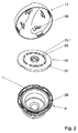
図2において、蓋本体6が上から見られ、蓋14が下から見られ、その間に係合環22が見られる。係合環22はその上側に、円に沿って設けられかつ中断部25.1を持つ第1のひれ25を有する。蓋14はその内側に適当な数の第2のひれ26を持ち、これらのひれ26はここでは鼻状で、係合環22の高さ位置には無関係に(従って内圧とは無関係に)、中断部25.1へはまる。係合環22は、下方へ曲げられるその縁22.1(従ってその下側)に若干数の凹所27を持ち、その下降位置でこれらの凹所27へ、蓋本体6の皿7の外縁にあって半径方向内方へ向く突起28がはまる。内圧が第1の閾値(例えば40mBar)を超過して膜20を持上げると、突起28が凹所27と係合しなくなるほど小さい高さを、凹所27が持っている(その場合回転結合が中断される)。 In FIG. 2, the lid body 6 is seen from above, the
図3では、選択的な回転結合を行う部分25〜28が一層よくわかる。膜20は、その円環状外縁に、周囲に延びる隆起20.1を持ち、この隆起20.1が、締付け環30により、蓋本体6の皿状部分上に密に保持されている。締付け環30は、若干数のスナップかぎ30.1により蓋本体6にクリップ止めされている。隆起20.1には、半径方向内方へベロー状円環面20.2が続き、この円環面20.2内に作用面20.3即ち本来の膜が張られている。この膜は、以下に述べるように付加的な逃がし弁を形成するため、その下側に板31が当接する円環である。 In FIG. 3, the
再び図1において、逃がし弁は大部分を蓋ハウジングの内部にある空間43に収容されている。逃がし弁は弁体40により形成される。弁体40は、上方を大きい面の隔壁40.4により閉鎖されて下方へ延びる円筒40.2であり、その上縁でフランジ40.1が外方へ突出して、円環状膜20の作用面20.3を内側及び下から部分的に覆っている。円筒40.2は下方で拡張部に終わり、この拡張部にばね受け42が支持されている。ばね受け42と膜20の下側にある板31との間に別の圧縮ばね41があって、弁体40のフランジ40.1を膜20へ押付けている。逃がし弁が密でなくなるか又は更に開くことなしに、弁体40が膜20の変形に追従することができる。 Referring again to FIG. 1, most of the relief valve is accommodated in the
容器の内部圧力が一層高い第2の閾値(例えば400mBar)を超過する時に初めて、大きい面積の隔壁40.4に作用する圧力の力が、別の圧縮ばね41の力に打勝ち、フランジ40.1が膜20から離れ、逃がし弁が開き、流出する燃料蒸気が係合環22にある穴22.1を通って逃げることができる。一層高い閾値に応じて、別の圧縮ばね41は圧縮ばね23より強い。 Only when the internal pressure of the container exceeds a higher second threshold (eg 400 mBar), the pressure force acting on the large partition wall 40.4 overcomes the force of the
上述した実施形態とは異なる種々の実施形態は本発明の範囲内にある。係合環22と蓋14との解除可能な回転結合を設けることもでき、そのために連結素子25〜28が適当に改善される。連結素子が係合環22の一方の側で永久的な回転結合を行い、他方の側でその高さ位置に関係して一次的な回転結合を行う限り、連結素子を任意に構成することができる。 Various embodiments different from those described above are within the scope of the present invention. It is also possible to provide a releasable rotational connection between the
Claims (4)
a)蓋本体(6)と蓋(14)との間に、圧縮ばね(23)の荷重を受ける係合環(22)が設けられ、係合環(22)の一方の側が蓋(14)に相対回転しないように結合され、他方の側が、容器の内部に存在する圧力に関係して、蓋本体(6)に相対回転しないように結合可能であり、
b)容器の内部に存在する圧力が、膜(20)を介して係合環(22)に作用して、この圧力が特定の第1の閾値を超過する時、圧縮ばね(23)の力に抗して係合環(22)を変位させ、こうして相対回転しない結合を解除し、
c)蓋本体(6)と同心的な逃がし弁(40)が、別の圧縮ばね(41)を持ち、容器の内部の圧力が第1の圧力より高い第2の閾値を超過する時、逃がし弁(40)が開く
ものにおいて、
d)外縁(20.1)を蓋本体(6)に取付けられる膜(20)が円環の形状を持ち、この円環が係合環(22)から遠い方の側で円環状板(31)により支持され、外側縁(20.1)を蓋本体(6)に密に取付けられ、
e)円環状の膜(20)の半径方向内側に逃がし弁の弁体(40)が設けられ、この弁体のフランジ(40.1)を形成する上縁が膜(20)に内側から係合し、従って逃がし弁が閉じる際、膜の作用面(20.3)が、少なくとも部分的にフランジ(40.1)と円環状板(31)との間に挟まれ、
f)そのために別の圧縮ばね(41)が、円環状板(31)と逃がし弁の弁体(40)の下端に設けられるばね受け(42)との間に設けられ、
g)逃がし弁の弁体(40)が、フランジ(40.1)から下方へ、上部で閉じた円筒(40.2)を形成し、蓋本体(6)の内部に形成される円筒状空間(43)に円筒(40.2)が収容され、
h)逃がし弁(40)が蓋本体(6)に同心的に設けられて、燃料容器と膜(20)との圧力接続が、逃がし弁(40)外でかつ蓋本体(6)の内壁内で行われる
ことを特徴とする、閉鎖蓋。A closure lid for a container that receives internal pressure, the lid body (6) that can be fixed to the receptacle (1) of the container by rotation, and a lid (14) that includes a handle (15) and that can be coupled to the lid body (6) ) And a relief valve,
a) An engagement ring (22) that receives the load of the compression spring (23) is provided between the lid body (6) and the lid (14), and one side of the engagement ring (22) is the lid (14). The other side can be coupled to the lid body (6) so as not to rotate relative to the pressure present inside the container,
b) When the pressure present inside the container acts on the engagement ring (22) via the membrane (20) and this pressure exceeds a certain first threshold, the force of the compression spring (23) To disengage the engagement ring (22) against this, thus releasing the non-rotating connection,
c) The relief valve (40) concentric with the lid body (6) has a separate compression spring (41) and the relief when the pressure inside the container exceeds a second threshold higher than the first pressure. In the valve (40) opening,
d) The membrane (20) for attaching the outer edge (20.1) to the lid body (6) has an annular shape, and the annular plate (31) on the side far from the engagement ring (22). ), The outer edge (20.1) is tightly attached to the lid body (6),
e) A relief valve body (40) is provided radially inward of the annular membrane (20), and the upper edge forming the flange (40.1) of the valve body is engaged with the membrane (20) from the inside. And therefore when the relief valve closes, the working surface (20.3) of the membrane is at least partially sandwiched between the flange (40.1) and the annular plate (31),
f) For this purpose, another compression spring (41) is provided between the annular plate (31) and a spring receiver (42) provided at the lower end of the valve body (40) of the relief valve,
g) Cylindrical space in which the valve body (40) of the relief valve forms a cylinder (40.2) closed at the top downward from the flange (40.1), and is formed inside the lid body (6). (43) contains the cylinder (40.2) ,
h) A relief valve (40) is provided concentrically on the lid body (6) so that the pressure connection between the fuel container and the membrane (20) is outside the relief valve (40) and inside the inner wall of the lid body (6). A closure lid, characterized in that it is carried out in
Applications Claiming Priority (3)
| Application Number | Priority Date | Filing Date | Title |
|---|---|---|---|
| DE102007043033.9 | 2007-09-11 | ||
| DE102007043033A DE102007043033A1 (en) | 2007-09-11 | 2007-09-11 | Cover for internal pressurized containers with safety function and cap for a fuel tank |
| PCT/EP2008/062105 WO2009034149A1 (en) | 2007-09-11 | 2008-09-11 | Closure cover for tanks under internal pressure, with a safety function, and closure cover for a fuel tank |
Publications (2)
| Publication Number | Publication Date |
|---|---|
| JP2010538919A JP2010538919A (en) | 2010-12-16 |
| JP5408453B2 true JP5408453B2 (en) | 2014-02-05 |
Family
ID=40030357
Family Applications (1)
| Application Number | Title | Priority Date | Filing Date |
|---|---|---|---|
| JP2010526243A Expired - Fee Related JP5408453B2 (en) | 2007-09-11 | 2008-09-11 | Lid for containers with safety function under internal pressure and closing lid for fuel tank |
Country Status (4)
| Country | Link |
|---|---|
| US (1) | US8430261B2 (en) |
| JP (1) | JP5408453B2 (en) |
| DE (2) | DE102007043033A1 (en) |
| WO (1) | WO2009034149A1 (en) |
Families Citing this family (14)
| Publication number | Priority date | Publication date | Assignee | Title |
|---|---|---|---|---|
| DE102010018126B4 (en) * | 2010-04-24 | 2023-11-16 | Volkswagen Ag | Closing device for a fuel tank |
| EP2738953A1 (en) | 2011-01-07 | 2014-06-04 | Interdigital Patent Holdings, Inc. | Communicating channel state information (CSI) of multiple transmission points |
| EP2742716A1 (en) | 2011-08-12 | 2014-06-18 | Interdigital Patent Holdings, Inc. | Interference measurement in wireless networks |
| US8701920B2 (en) | 2011-08-27 | 2014-04-22 | GM Global Technology Operations LLC | Fuel cap |
| EP2856661A2 (en) | 2012-06-04 | 2015-04-08 | Interdigital Patent Holdings, Inc. | Communicating channel state information (csi) of multiple transmission points |
| CN105191203B (en) | 2013-05-08 | 2019-05-03 | 交互数字专利控股公司 | Methods, systems and apparatus for Network Assisted Interference Cancellation and/or Suppression (NAICS) in Long Term Evolution (LTE) systems |
| EP2873545B1 (en) | 2013-10-17 | 2018-05-02 | Magna Steyr Fuel Systems GmbH | Locking system |
| DE102016114130B3 (en) * | 2016-07-29 | 2017-05-11 | Joma-Polytec Gmbh | filler cap |
| DE102017120520A1 (en) * | 2017-09-06 | 2019-03-07 | Aesculap Ag | Sterile container with vapor permeable seal |
| US11383902B2 (en) | 2018-07-17 | 2022-07-12 | Bemis Manufacturing Company | Pressure relief cap |
| EP3632730B1 (en) * | 2018-10-01 | 2021-05-26 | Andreas Stihl AG & Co. KG | Closure cap for an operating liquid tank |
| DE202020103899U1 (en) * | 2020-07-06 | 2021-10-08 | KÖHLER AUTOMOBILTECHNIK GmbH | Tank cap for automobiles |
| USD1036799S1 (en) * | 2022-01-27 | 2024-07-23 | Yun Li | Clean water tank of vacuum cleaner |
| US12085216B2 (en) | 2022-02-17 | 2024-09-10 | Arctic Cat Inc. | Multi-use fuel filler tube |
Family Cites Families (9)
| Publication number | Priority date | Publication date | Assignee | Title |
|---|---|---|---|---|
| US5732841A (en) | 1996-03-19 | 1998-03-31 | Tesma International Inc. | Fuel cap |
| JP3648648B2 (en) * | 1996-03-26 | 2005-05-18 | カルソニックプロダクツ株式会社 | Device for preventing closing of fuel cap and fuel theft preventing device for vehicle |
| JP3386995B2 (en) | 1997-03-31 | 2003-03-17 | 豊田合成株式会社 | Fuel cap |
| DE19753592A1 (en) * | 1997-12-03 | 1999-06-10 | Heinrich Reutter | Sealing cover |
| DE19923775A1 (en) | 1999-05-22 | 2000-11-23 | Heinrich Reutter | Closure cover for automotive radiators |
| AT4444U1 (en) | 2000-05-23 | 2001-07-25 | Tesma Motoren Getriebetechnik | FUEL CAP |
| DE20201082U1 (en) | 2002-01-24 | 2003-06-05 | Reutter, Heinrich, 71336 Waiblingen | Cover for automobile radiator |
| US7163117B2 (en) * | 2002-05-01 | 2007-01-16 | Stant Manufacturing Inc. | Static charge dissipater for filler neck closure |
| JP4406546B2 (en) | 2003-09-05 | 2010-01-27 | 豊田合成株式会社 | Cap device |
-
2007
- 2007-09-11 DE DE102007043033A patent/DE102007043033A1/en not_active Withdrawn
-
2008
- 2008-09-11 WO PCT/EP2008/062105 patent/WO2009034149A1/en active Application Filing
- 2008-09-11 US US12/677,129 patent/US8430261B2/en active Active
- 2008-09-11 JP JP2010526243A patent/JP5408453B2/en not_active Expired - Fee Related
- 2008-09-11 DE DE112008002450T patent/DE112008002450A5/en not_active Ceased
Also Published As
| Publication number | Publication date |
|---|---|
| DE112008002450A5 (en) | 2010-07-29 |
| JP2010538919A (en) | 2010-12-16 |
| US20110017734A1 (en) | 2011-01-27 |
| WO2009034149A1 (en) | 2009-03-19 |
| US8430261B2 (en) | 2013-04-30 |
| DE102007043033A1 (en) | 2009-03-12 |
Similar Documents
| Publication | Publication Date | Title |
|---|---|---|
| JP5408453B2 (en) | Lid for containers with safety function under internal pressure and closing lid for fuel tank | |
| EP1506120B1 (en) | Hose direct canister lid | |
| RU2529082C2 (en) | Set of container and lid | |
| US20170050775A1 (en) | Mechanically sealed container cap | |
| US6701952B1 (en) | Valve and method for fitting it to a tank | |
| JP2008528175A (en) | Leak resistant cup | |
| US9386869B2 (en) | Cover device for a drink container | |
| CN110822139B (en) | Gland removing cover | |
| CN112810994A (en) | Container closure with vent seal | |
| JP6186665B1 (en) | Cap unit and beverage container | |
| KR101876732B1 (en) | Container structure | |
| JP2019508330A (en) | Fluid product dispenser | |
| CN111268275B (en) | Pressure reducing cover | |
| CN115703563A (en) | Cap unit and beverage container | |
| JP4974063B2 (en) | Storage container | |
| JP4697740B2 (en) | Airtight container with lid | |
| JP5380342B2 (en) | container | |
| JP4515372B2 (en) | Liquid container lid structure | |
| JP7321616B1 (en) | Containers with Lids and Lid Units | |
| JP6507150B2 (en) | Dropper container | |
| JP4588611B2 (en) | Liquid container lid structure | |
| JP7313248B2 (en) | dropper container | |
| JP4588609B2 (en) | Liquid container lid structure | |
| JPS5920838Y2 (en) | Pump type liquid container | |
| JP4925164B2 (en) | Airtight container with lid |
Legal Events
| Date | Code | Title | Description |
|---|---|---|---|
| A977 | Report on retrieval |
Free format text: JAPANESE INTERMEDIATE CODE: A971007 Effective date: 20120711 |
|
| A131 | Notification of reasons for refusal |
Free format text: JAPANESE INTERMEDIATE CODE: A131 Effective date: 20120724 |
|
| A521 | Request for written amendment filed |
Free format text: JAPANESE INTERMEDIATE CODE: A523 Effective date: 20121023 |
|
| A02 | Decision of refusal |
Free format text: JAPANESE INTERMEDIATE CODE: A02 Effective date: 20130409 |
|
| A521 | Request for written amendment filed |
Free format text: JAPANESE INTERMEDIATE CODE: A523 Effective date: 20130808 |
|
| A911 | Transfer to examiner for re-examination before appeal (zenchi) |
Free format text: JAPANESE INTERMEDIATE CODE: A911 Effective date: 20130903 |
|
| TRDD | Decision of grant or rejection written | ||
| A01 | Written decision to grant a patent or to grant a registration (utility model) |
Free format text: JAPANESE INTERMEDIATE CODE: A01 Effective date: 20131008 |
|
| A61 | First payment of annual fees (during grant procedure) |
Free format text: JAPANESE INTERMEDIATE CODE: A61 Effective date: 20131022 |
|
| R150 | Certificate of patent or registration of utility model |
Ref document number: 5408453 Country of ref document: JP Free format text: JAPANESE INTERMEDIATE CODE: R150 |
|
| R250 | Receipt of annual fees |
Free format text: JAPANESE INTERMEDIATE CODE: R250 |
|
| R250 | Receipt of annual fees |
Free format text: JAPANESE INTERMEDIATE CODE: R250 |
|
| R250 | Receipt of annual fees |
Free format text: JAPANESE INTERMEDIATE CODE: R250 |
|
| R250 | Receipt of annual fees |
Free format text: JAPANESE INTERMEDIATE CODE: R250 |
|
| R250 | Receipt of annual fees |
Free format text: JAPANESE INTERMEDIATE CODE: R250 |
|
| R250 | Receipt of annual fees |
Free format text: JAPANESE INTERMEDIATE CODE: R250 |
|
| R250 | Receipt of annual fees |
Free format text: JAPANESE INTERMEDIATE CODE: R250 |
|
| LAPS | Cancellation because of no payment of annual fees |