JP5404384B2 - Process for partial dehydrogenation of heterogeneous catalyst of at least one hydrocarbon to be dehydrogenated - Google Patents
Process for partial dehydrogenation of heterogeneous catalyst of at least one hydrocarbon to be dehydrogenated Download PDFInfo
- Publication number
- JP5404384B2 JP5404384B2 JP2009502061A JP2009502061A JP5404384B2 JP 5404384 B2 JP5404384 B2 JP 5404384B2 JP 2009502061 A JP2009502061 A JP 2009502061A JP 2009502061 A JP2009502061 A JP 2009502061A JP 5404384 B2 JP5404384 B2 JP 5404384B2
- Authority
- JP
- Japan
- Prior art keywords
- gas
- inflow
- dehydrogenated
- hydrocarbon
- flow
- Prior art date
- Legal status (The legal status is an assumption and is not a legal conclusion. Google has not performed a legal analysis and makes no representation as to the accuracy of the status listed.)
- Expired - Fee Related
Links
- 229930195733 hydrocarbon Natural products 0.000 title claims description 129
- 150000002430 hydrocarbons Chemical class 0.000 title claims description 129
- 238000000034 method Methods 0.000 title claims description 109
- 239000004215 Carbon black (E152) Substances 0.000 title claims description 91
- 238000006356 dehydrogenation reaction Methods 0.000 title claims description 69
- 230000008569 process Effects 0.000 title claims description 52
- 230000036961 partial effect Effects 0.000 title claims description 44
- 239000002638 heterogeneous catalyst Substances 0.000 title claims description 37
- 239000007789 gas Substances 0.000 claims description 296
- 239000003054 catalyst Substances 0.000 claims description 218
- 239000012495 reaction gas Substances 0.000 claims description 175
- 239000000203 mixture Substances 0.000 claims description 172
- 229910052760 oxygen Inorganic materials 0.000 claims description 92
- MYMOFIZGZYHOMD-UHFFFAOYSA-N Dioxygen Chemical compound O=O MYMOFIZGZYHOMD-UHFFFAOYSA-N 0.000 claims description 82
- 239000001301 oxygen Substances 0.000 claims description 80
- ATUOYWHBWRKTHZ-UHFFFAOYSA-N Propane Chemical compound CCC ATUOYWHBWRKTHZ-UHFFFAOYSA-N 0.000 claims description 60
- UFHFLCQGNIYNRP-UHFFFAOYSA-N Hydrogen Chemical compound [H][H] UFHFLCQGNIYNRP-UHFFFAOYSA-N 0.000 claims description 43
- 229910052739 hydrogen Inorganic materials 0.000 claims description 40
- 239000001257 hydrogen Substances 0.000 claims description 38
- 239000001294 propane Substances 0.000 claims description 30
- XLYOFNOQVPJJNP-UHFFFAOYSA-N water Substances O XLYOFNOQVPJJNP-UHFFFAOYSA-N 0.000 claims description 29
- 238000002485 combustion reaction Methods 0.000 claims description 27
- 230000005484 gravity Effects 0.000 claims description 21
- 230000003647 oxidation Effects 0.000 claims description 18
- 238000007254 oxidation reaction Methods 0.000 claims description 18
- 238000011144 upstream manufacturing Methods 0.000 claims description 9
- 229910001882 dioxygen Inorganic materials 0.000 claims description 7
- UGFAIRIUMAVXCW-UHFFFAOYSA-N Carbon monoxide Chemical class [O+]#[C-] UGFAIRIUMAVXCW-UHFFFAOYSA-N 0.000 claims description 5
- 229910002090 carbon oxide Inorganic materials 0.000 claims description 5
- 230000000694 effects Effects 0.000 claims description 3
- 238000005303 weighing Methods 0.000 claims description 2
- QVGXLLKOCUKJST-UHFFFAOYSA-N atomic oxygen Chemical compound [O] QVGXLLKOCUKJST-UHFFFAOYSA-N 0.000 claims 6
- 239000002815 homogeneous catalyst Substances 0.000 claims 1
- 239000000047 product Substances 0.000 description 42
- 238000006243 chemical reaction Methods 0.000 description 38
- 238000009826 distribution Methods 0.000 description 29
- QQONPFPTGQHPMA-UHFFFAOYSA-N Propene Chemical compound CC=C QQONPFPTGQHPMA-UHFFFAOYSA-N 0.000 description 26
- SMZOUWXMTYCWNB-UHFFFAOYSA-N 2-(2-methoxy-5-methylphenyl)ethanamine Chemical compound COC1=CC=C(C)C=C1CCN SMZOUWXMTYCWNB-UHFFFAOYSA-N 0.000 description 24
- NIXOWILDQLNWCW-UHFFFAOYSA-N 2-Propenoic acid Natural products OC(=O)C=C NIXOWILDQLNWCW-UHFFFAOYSA-N 0.000 description 24
- IJGRMHOSHXDMSA-UHFFFAOYSA-N Atomic nitrogen Chemical compound N#N IJGRMHOSHXDMSA-UHFFFAOYSA-N 0.000 description 24
- 125000004805 propylene group Chemical group [H]C([H])([H])C([H])([*:1])C([H])([H])[*:2] 0.000 description 21
- 239000000463 material Substances 0.000 description 20
- 239000003570 air Substances 0.000 description 15
- 239000011261 inert gas Substances 0.000 description 15
- HGINCPLSRVDWNT-UHFFFAOYSA-N Acrolein Chemical compound C=CC=O HGINCPLSRVDWNT-UHFFFAOYSA-N 0.000 description 14
- 239000000543 intermediate Substances 0.000 description 14
- 241000446313 Lamella Species 0.000 description 13
- VQTUBCCKSQIDNK-UHFFFAOYSA-N Isobutene Chemical compound CC(C)=C VQTUBCCKSQIDNK-UHFFFAOYSA-N 0.000 description 12
- 229910052757 nitrogen Inorganic materials 0.000 description 12
- VYPSYNLAJGMNEJ-UHFFFAOYSA-N Silicium dioxide Chemical compound O=[Si]=O VYPSYNLAJGMNEJ-UHFFFAOYSA-N 0.000 description 9
- 238000005192 partition Methods 0.000 description 9
- 230000008929 regeneration Effects 0.000 description 9
- 238000011069 regeneration method Methods 0.000 description 9
- 239000000523 sample Substances 0.000 description 9
- OTMSDBZUPAUEDD-UHFFFAOYSA-N Ethane Chemical compound CC OTMSDBZUPAUEDD-UHFFFAOYSA-N 0.000 description 8
- GWEVSGVZZGPLCZ-UHFFFAOYSA-N Titan oxide Chemical compound O=[Ti]=O GWEVSGVZZGPLCZ-UHFFFAOYSA-N 0.000 description 8
- NNPPMTNAJDCUHE-UHFFFAOYSA-N isobutane Chemical compound CC(C)C NNPPMTNAJDCUHE-UHFFFAOYSA-N 0.000 description 8
- 238000002156 mixing Methods 0.000 description 8
- BASFCYQUMIYNBI-UHFFFAOYSA-N platinum Chemical compound [Pt] BASFCYQUMIYNBI-UHFFFAOYSA-N 0.000 description 8
- OKTJSMMVPCPJKN-UHFFFAOYSA-N Carbon Chemical compound [C] OKTJSMMVPCPJKN-UHFFFAOYSA-N 0.000 description 7
- VGGSQFUCUMXWEO-UHFFFAOYSA-N Ethene Chemical compound C=C VGGSQFUCUMXWEO-UHFFFAOYSA-N 0.000 description 7
- 239000005977 Ethylene Substances 0.000 description 7
- 229910002091 carbon monoxide Inorganic materials 0.000 description 7
- 239000000470 constituent Substances 0.000 description 7
- 229910052751 metal Inorganic materials 0.000 description 7
- 239000002184 metal Substances 0.000 description 7
- 239000010935 stainless steel Substances 0.000 description 7
- 229910001220 stainless steel Inorganic materials 0.000 description 7
- QTBSBXVTEAMEQO-UHFFFAOYSA-N Acetic acid Chemical compound CC(O)=O QTBSBXVTEAMEQO-UHFFFAOYSA-N 0.000 description 6
- 239000011324 bead Substances 0.000 description 6
- 229910052799 carbon Inorganic materials 0.000 description 6
- 239000003701 inert diluent Substances 0.000 description 6
- VNWKTOKETHGBQD-UHFFFAOYSA-N methane Chemical compound C VNWKTOKETHGBQD-UHFFFAOYSA-N 0.000 description 6
- 235000012239 silicon dioxide Nutrition 0.000 description 6
- 230000007704 transition Effects 0.000 description 6
- 238000003466 welding Methods 0.000 description 6
- VXNZUUAINFGPBY-UHFFFAOYSA-N 1-Butene Chemical compound CCC=C VXNZUUAINFGPBY-UHFFFAOYSA-N 0.000 description 5
- 239000012018 catalyst precursor Substances 0.000 description 5
- 150000001875 compounds Chemical class 0.000 description 5
- 238000002347 injection Methods 0.000 description 5
- 239000007924 injection Substances 0.000 description 5
- 238000009413 insulation Methods 0.000 description 5
- 230000001681 protective effect Effects 0.000 description 5
- 230000002829 reductive effect Effects 0.000 description 5
- 238000005406 washing Methods 0.000 description 5
- KAKZBPTYRLMSJV-UHFFFAOYSA-N Butadiene Chemical compound C=CC=C KAKZBPTYRLMSJV-UHFFFAOYSA-N 0.000 description 4
- CURLTUGMZLYLDI-UHFFFAOYSA-N Carbon dioxide Chemical compound O=C=O CURLTUGMZLYLDI-UHFFFAOYSA-N 0.000 description 4
- MCMNRKCIXSYSNV-UHFFFAOYSA-N ZrO2 Inorganic materials O=[Zr]=O MCMNRKCIXSYSNV-UHFFFAOYSA-N 0.000 description 4
- 239000007864 aqueous solution Substances 0.000 description 4
- IAQRGUVFOMOMEM-UHFFFAOYSA-N but-2-ene Chemical compound CC=CC IAQRGUVFOMOMEM-UHFFFAOYSA-N 0.000 description 4
- 230000003197 catalytic effect Effects 0.000 description 4
- 238000009833 condensation Methods 0.000 description 4
- 230000005494 condensation Effects 0.000 description 4
- 238000001816 cooling Methods 0.000 description 4
- 230000007423 decrease Effects 0.000 description 4
- 238000013461 design Methods 0.000 description 4
- -1 ethane (~ ethylene) Chemical class 0.000 description 4
- 239000001282 iso-butane Substances 0.000 description 4
- MRELNEQAGSRDBK-UHFFFAOYSA-N lanthanum(3+);oxygen(2-) Chemical compound [O-2].[O-2].[O-2].[La+3].[La+3] MRELNEQAGSRDBK-UHFFFAOYSA-N 0.000 description 4
- 239000010410 layer Substances 0.000 description 4
- 239000007788 liquid Substances 0.000 description 4
- 238000004519 manufacturing process Methods 0.000 description 4
- TWNQGVIAIRXVLR-UHFFFAOYSA-N oxo(oxoalumanyloxy)alumane Chemical compound O=[Al]O[Al]=O TWNQGVIAIRXVLR-UHFFFAOYSA-N 0.000 description 4
- RVTZCBVAJQQJTK-UHFFFAOYSA-N oxygen(2-);zirconium(4+) Chemical compound [O-2].[O-2].[Zr+4] RVTZCBVAJQQJTK-UHFFFAOYSA-N 0.000 description 4
- 229910052697 platinum Inorganic materials 0.000 description 4
- 150000003254 radicals Chemical class 0.000 description 4
- 238000000926 separation method Methods 0.000 description 4
- 238000007086 side reaction Methods 0.000 description 4
- 239000004408 titanium dioxide Substances 0.000 description 4
- ATJFFYVFTNAWJD-UHFFFAOYSA-N Tin Chemical compound [Sn] ATJFFYVFTNAWJD-UHFFFAOYSA-N 0.000 description 3
- 238000010521 absorption reaction Methods 0.000 description 3
- 230000015572 biosynthetic process Effects 0.000 description 3
- 238000009835 boiling Methods 0.000 description 3
- 239000000919 ceramic Substances 0.000 description 3
- 230000008859 change Effects 0.000 description 3
- 239000002800 charge carrier Substances 0.000 description 3
- 239000013078 crystal Substances 0.000 description 3
- 238000011049 filling Methods 0.000 description 3
- 239000012530 fluid Substances 0.000 description 3
- PCHJSUWPFVWCPO-UHFFFAOYSA-N gold Chemical compound [Au] PCHJSUWPFVWCPO-UHFFFAOYSA-N 0.000 description 3
- 229910052737 gold Inorganic materials 0.000 description 3
- 239000010931 gold Substances 0.000 description 3
- YCOZIPAWZNQLMR-UHFFFAOYSA-N heptane - octane Natural products CCCCCCCCCCCCCCC YCOZIPAWZNQLMR-UHFFFAOYSA-N 0.000 description 3
- 238000003780 insertion Methods 0.000 description 3
- 230000037431 insertion Effects 0.000 description 3
- 238000000465 moulding Methods 0.000 description 3
- IJDNQMDRQITEOD-UHFFFAOYSA-N n-butane Chemical compound CCCC IJDNQMDRQITEOD-UHFFFAOYSA-N 0.000 description 3
- 230000002093 peripheral effect Effects 0.000 description 3
- 239000012071 phase Substances 0.000 description 3
- 229910052700 potassium Inorganic materials 0.000 description 3
- 239000010453 quartz Substances 0.000 description 3
- 239000000376 reactant Substances 0.000 description 3
- 238000007789 sealing Methods 0.000 description 3
- 239000007787 solid Substances 0.000 description 3
- 229910052718 tin Inorganic materials 0.000 description 3
- MHCVCKDNQYMGEX-UHFFFAOYSA-N 1,1'-biphenyl;phenoxybenzene Chemical group C1=CC=CC=C1C1=CC=CC=C1.C=1C=CC=CC=1OC1=CC=CC=C1 MHCVCKDNQYMGEX-UHFFFAOYSA-N 0.000 description 2
- QGZKDVFQNNGYKY-UHFFFAOYSA-N Ammonia Chemical compound N QGZKDVFQNNGYKY-UHFFFAOYSA-N 0.000 description 2
- NIQCNGHVCWTJSM-UHFFFAOYSA-N Dimethyl phthalate Chemical compound COC(=O)C1=CC=CC=C1C(=O)OC NIQCNGHVCWTJSM-UHFFFAOYSA-N 0.000 description 2
- YNQLUTRBYVCPMQ-UHFFFAOYSA-N Ethylbenzene Chemical compound CCC1=CC=CC=C1 YNQLUTRBYVCPMQ-UHFFFAOYSA-N 0.000 description 2
- 241000264877 Hippospongia communis Species 0.000 description 2
- XEEYBQQBJWHFJM-UHFFFAOYSA-N Iron Chemical compound [Fe] XEEYBQQBJWHFJM-UHFFFAOYSA-N 0.000 description 2
- BZLVMXJERCGZMT-UHFFFAOYSA-N Methyl tert-butyl ether Chemical compound COC(C)(C)C BZLVMXJERCGZMT-UHFFFAOYSA-N 0.000 description 2
- PXHVJJICTQNCMI-UHFFFAOYSA-N Nickel Chemical compound [Ni] PXHVJJICTQNCMI-UHFFFAOYSA-N 0.000 description 2
- KDLHZDBZIXYQEI-UHFFFAOYSA-N Palladium Chemical compound [Pd] KDLHZDBZIXYQEI-UHFFFAOYSA-N 0.000 description 2
- XUIMIQQOPSSXEZ-UHFFFAOYSA-N Silicon Chemical compound [Si] XUIMIQQOPSSXEZ-UHFFFAOYSA-N 0.000 description 2
- PPBRXRYQALVLMV-UHFFFAOYSA-N Styrene Chemical compound C=CC1=CC=CC=C1 PPBRXRYQALVLMV-UHFFFAOYSA-N 0.000 description 2
- 229910052768 actinide Inorganic materials 0.000 description 2
- 150000001255 actinides Chemical class 0.000 description 2
- 125000002015 acyclic group Chemical group 0.000 description 2
- 150000001335 aliphatic alkanes Chemical class 0.000 description 2
- 238000013459 approach Methods 0.000 description 2
- 238000009529 body temperature measurement Methods 0.000 description 2
- 239000006227 byproduct Substances 0.000 description 2
- 239000001569 carbon dioxide Substances 0.000 description 2
- 229910002092 carbon dioxide Inorganic materials 0.000 description 2
- 229910000420 cerium oxide Inorganic materials 0.000 description 2
- 239000011247 coating layer Substances 0.000 description 2
- 230000000052 comparative effect Effects 0.000 description 2
- 230000008878 coupling Effects 0.000 description 2
- 238000010168 coupling process Methods 0.000 description 2
- 238000005859 coupling reaction Methods 0.000 description 2
- 238000002425 crystallisation Methods 0.000 description 2
- 230000008025 crystallization Effects 0.000 description 2
- RWGFKTVRMDUZSP-UHFFFAOYSA-N cumene Chemical compound CC(C)C1=CC=CC=C1 RWGFKTVRMDUZSP-UHFFFAOYSA-N 0.000 description 2
- DIOQZVSQGTUSAI-UHFFFAOYSA-N decane Chemical compound CCCCCCCCCC DIOQZVSQGTUSAI-UHFFFAOYSA-N 0.000 description 2
- 230000003247 decreasing effect Effects 0.000 description 2
- 238000010586 diagram Methods 0.000 description 2
- 238000010790 dilution Methods 0.000 description 2
- 239000012895 dilution Substances 0.000 description 2
- XNMQEEKYCVKGBD-UHFFFAOYSA-N dimethylacetylene Natural products CC#CC XNMQEEKYCVKGBD-UHFFFAOYSA-N 0.000 description 2
- USIUVYZYUHIAEV-UHFFFAOYSA-N diphenyl ether Chemical compound C=1C=CC=CC=1OC1=CC=CC=C1 USIUVYZYUHIAEV-UHFFFAOYSA-N 0.000 description 2
- 238000001035 drying Methods 0.000 description 2
- 239000002360 explosive Substances 0.000 description 2
- 230000006870 function Effects 0.000 description 2
- 239000011491 glass wool Substances 0.000 description 2
- 239000010439 graphite Substances 0.000 description 2
- 229910002804 graphite Inorganic materials 0.000 description 2
- 238000010438 heat treatment Methods 0.000 description 2
- 238000007210 heterogeneous catalysis Methods 0.000 description 2
- DCAYPVUWAIABOU-UHFFFAOYSA-N hexadecane Chemical compound CCCCCCCCCCCCCCCC DCAYPVUWAIABOU-UHFFFAOYSA-N 0.000 description 2
- 230000006872 improvement Effects 0.000 description 2
- 238000001802 infusion Methods 0.000 description 2
- 239000012774 insulation material Substances 0.000 description 2
- QWTDNUCVQCZILF-UHFFFAOYSA-N isopentane Chemical compound CCC(C)C QWTDNUCVQCZILF-UHFFFAOYSA-N 0.000 description 2
- 229910052747 lanthanoid Inorganic materials 0.000 description 2
- 150000002602 lanthanoids Chemical class 0.000 description 2
- 229910052746 lanthanum Inorganic materials 0.000 description 2
- FZLIPJUXYLNCLC-UHFFFAOYSA-N lanthanum atom Chemical compound [La] FZLIPJUXYLNCLC-UHFFFAOYSA-N 0.000 description 2
- 238000011068 loading method Methods 0.000 description 2
- 239000000395 magnesium oxide Substances 0.000 description 2
- CPLXHLVBOLITMK-UHFFFAOYSA-N magnesium oxide Inorganic materials [Mg]=O CPLXHLVBOLITMK-UHFFFAOYSA-N 0.000 description 2
- AXZKOIWUVFPNLO-UHFFFAOYSA-N magnesium;oxygen(2-) Chemical compound [O-2].[Mg+2] AXZKOIWUVFPNLO-UHFFFAOYSA-N 0.000 description 2
- 238000005259 measurement Methods 0.000 description 2
- 239000010445 mica Substances 0.000 description 2
- 229910052618 mica group Inorganic materials 0.000 description 2
- 239000012452 mother liquor Substances 0.000 description 2
- 229910052756 noble gas Inorganic materials 0.000 description 2
- 150000002835 noble gases Chemical class 0.000 description 2
- TVMXDCGIABBOFY-UHFFFAOYSA-N octane Chemical compound CCCCCCCC TVMXDCGIABBOFY-UHFFFAOYSA-N 0.000 description 2
- 239000003960 organic solvent Substances 0.000 description 2
- BMMGVYCKOGBVEV-UHFFFAOYSA-N oxo(oxoceriooxy)cerium Chemical compound [Ce]=O.O=[Ce]=O BMMGVYCKOGBVEV-UHFFFAOYSA-N 0.000 description 2
- 238000006116 polymerization reaction Methods 0.000 description 2
- 238000010926 purge Methods 0.000 description 2
- 238000007348 radical reaction Methods 0.000 description 2
- 230000009467 reduction Effects 0.000 description 2
- 239000012925 reference material Substances 0.000 description 2
- 239000000565 sealant Substances 0.000 description 2
- 239000003566 sealing material Substances 0.000 description 2
- 229910052710 silicon Inorganic materials 0.000 description 2
- 239000010703 silicon Substances 0.000 description 2
- 239000000377 silicon dioxide Substances 0.000 description 2
- 239000000243 solution Substances 0.000 description 2
- 239000000126 substance Substances 0.000 description 2
- 239000000725 suspension Substances 0.000 description 2
- BGHCVCJVXZWKCC-UHFFFAOYSA-N tetradecane Chemical compound CCCCCCCCCCCCCC BGHCVCJVXZWKCC-UHFFFAOYSA-N 0.000 description 2
- IIYFAKIEWZDVMP-UHFFFAOYSA-N tridecane Chemical compound CCCCCCCCCCCCC IIYFAKIEWZDVMP-UHFFFAOYSA-N 0.000 description 2
- 238000009827 uniform distribution Methods 0.000 description 2
- ZOXJGFHDIHLPTG-UHFFFAOYSA-N Boron Chemical compound [B] ZOXJGFHDIHLPTG-UHFFFAOYSA-N 0.000 description 1
- 229910052684 Cerium Inorganic materials 0.000 description 1
- 241000237942 Conidae Species 0.000 description 1
- 229940123457 Free radical scavenger Drugs 0.000 description 1
- GYHNNYVSQQEPJS-UHFFFAOYSA-N Gallium Chemical compound [Ga] GYHNNYVSQQEPJS-UHFFFAOYSA-N 0.000 description 1
- 206010021143 Hypoxia Diseases 0.000 description 1
- CERQOIWHTDAKMF-UHFFFAOYSA-N Methacrylic acid Chemical compound CC(=C)C(O)=O CERQOIWHTDAKMF-UHFFFAOYSA-N 0.000 description 1
- IMNFDUFMRHMDMM-UHFFFAOYSA-N N-Heptane Chemical compound CCCCCCC IMNFDUFMRHMDMM-UHFFFAOYSA-N 0.000 description 1
- OFBQJSOFQDEBGM-UHFFFAOYSA-N Pentane Chemical compound CCCCC OFBQJSOFQDEBGM-UHFFFAOYSA-N 0.000 description 1
- ZLMJMSJWJFRBEC-UHFFFAOYSA-N Potassium Chemical compound [K] ZLMJMSJWJFRBEC-UHFFFAOYSA-N 0.000 description 1
- 239000006004 Quartz sand Substances 0.000 description 1
- 229910000831 Steel Inorganic materials 0.000 description 1
- WGLPBDUCMAPZCE-UHFFFAOYSA-N Trioxochromium Chemical compound O=[Cr](=O)=O WGLPBDUCMAPZCE-UHFFFAOYSA-N 0.000 description 1
- 229910000611 Zinc aluminium Inorganic materials 0.000 description 1
- YKTSYUJCYHOUJP-UHFFFAOYSA-N [O--].[Al+3].[Al+3].[O-][Si]([O-])([O-])[O-] Chemical compound [O--].[Al+3].[Al+3].[O-][Si]([O-])([O-])[O-] YKTSYUJCYHOUJP-UHFFFAOYSA-N 0.000 description 1
- 239000002250 absorbent Substances 0.000 description 1
- 230000002745 absorbent Effects 0.000 description 1
- 230000009471 action Effects 0.000 description 1
- 125000001931 aliphatic group Chemical group 0.000 description 1
- 150000001338 aliphatic hydrocarbons Chemical class 0.000 description 1
- 150000001336 alkenes Chemical class 0.000 description 1
- 125000000217 alkyl group Chemical group 0.000 description 1
- 229910045601 alloy Inorganic materials 0.000 description 1
- 239000000956 alloy Substances 0.000 description 1
- XYLMUPLGERFSHI-UHFFFAOYSA-N alpha-Methylstyrene Chemical compound CC(=C)C1=CC=CC=C1 XYLMUPLGERFSHI-UHFFFAOYSA-N 0.000 description 1
- HXFVOUUOTHJFPX-UHFFFAOYSA-N alumane;zinc Chemical compound [AlH3].[Zn] HXFVOUUOTHJFPX-UHFFFAOYSA-N 0.000 description 1
- 239000012080 ambient air Substances 0.000 description 1
- 229910021529 ammonia Inorganic materials 0.000 description 1
- 239000003125 aqueous solvent Substances 0.000 description 1
- 229910052786 argon Inorganic materials 0.000 description 1
- 230000008901 benefit Effects 0.000 description 1
- 239000004305 biphenyl Substances 0.000 description 1
- 235000010290 biphenyl Nutrition 0.000 description 1
- 125000006267 biphenyl group Chemical group 0.000 description 1
- 229910052796 boron Inorganic materials 0.000 description 1
- 229910052792 caesium Inorganic materials 0.000 description 1
- TVFDJXOCXUVLDH-UHFFFAOYSA-N caesium atom Chemical compound [Cs] TVFDJXOCXUVLDH-UHFFFAOYSA-N 0.000 description 1
- 150000001721 carbon Chemical class 0.000 description 1
- 125000004432 carbon atom Chemical group C* 0.000 description 1
- 239000011203 carbon fibre reinforced carbon Substances 0.000 description 1
- 238000003763 carbonization Methods 0.000 description 1
- 150000001735 carboxylic acids Chemical class 0.000 description 1
- 230000015556 catabolic process Effects 0.000 description 1
- 238000007084 catalytic combustion reaction Methods 0.000 description 1
- 229910010293 ceramic material Inorganic materials 0.000 description 1
- ZMIGMASIKSOYAM-UHFFFAOYSA-N cerium Chemical compound [Ce][Ce][Ce][Ce][Ce][Ce][Ce][Ce][Ce][Ce][Ce][Ce][Ce][Ce][Ce][Ce][Ce][Ce][Ce][Ce][Ce][Ce][Ce][Ce][Ce][Ce][Ce][Ce][Ce][Ce][Ce][Ce][Ce][Ce][Ce][Ce][Ce][Ce] ZMIGMASIKSOYAM-UHFFFAOYSA-N 0.000 description 1
- DGLFSNZWRYADFC-UHFFFAOYSA-N chembl2334586 Chemical compound C1CCC2=CN=C(N)N=C2C2=C1NC1=CC=C(C#CC(C)(O)C)C=C12 DGLFSNZWRYADFC-UHFFFAOYSA-N 0.000 description 1
- 239000007795 chemical reaction product Substances 0.000 description 1
- 229910000423 chromium oxide Inorganic materials 0.000 description 1
- 239000004927 clay Substances 0.000 description 1
- 239000003245 coal Substances 0.000 description 1
- 239000011248 coating agent Substances 0.000 description 1
- 238000000576 coating method Methods 0.000 description 1
- 230000008602 contraction Effects 0.000 description 1
- 238000012937 correction Methods 0.000 description 1
- 150000001924 cycloalkanes Chemical class 0.000 description 1
- 150000001925 cycloalkenes Chemical class 0.000 description 1
- 230000002950 deficient Effects 0.000 description 1
- 238000006731 degradation reaction Methods 0.000 description 1
- 230000018044 dehydration Effects 0.000 description 1
- 238000006297 dehydration reaction Methods 0.000 description 1
- 150000001993 dienes Chemical class 0.000 description 1
- 238000009792 diffusion process Methods 0.000 description 1
- AFABGHUZZDYHJO-UHFFFAOYSA-N dimethyl butane Natural products CCCC(C)C AFABGHUZZDYHJO-UHFFFAOYSA-N 0.000 description 1
- FBSAITBEAPNWJG-UHFFFAOYSA-N dimethyl phthalate Natural products CC(=O)OC1=CC=CC=C1OC(C)=O FBSAITBEAPNWJG-UHFFFAOYSA-N 0.000 description 1
- 229960001826 dimethylphthalate Drugs 0.000 description 1
- 238000007599 discharging Methods 0.000 description 1
- 238000006073 displacement reaction Methods 0.000 description 1
- SNRUBQQJIBEYMU-UHFFFAOYSA-N dodecane Chemical compound CCCCCCCCCCCC SNRUBQQJIBEYMU-UHFFFAOYSA-N 0.000 description 1
- 239000000428 dust Substances 0.000 description 1
- 230000008030 elimination Effects 0.000 description 1
- 238000003379 elimination reaction Methods 0.000 description 1
- 230000007717 exclusion Effects 0.000 description 1
- 239000000284 extract Substances 0.000 description 1
- 230000002349 favourable effect Effects 0.000 description 1
- 238000005194 fractionation Methods 0.000 description 1
- 239000012634 fragment Substances 0.000 description 1
- 239000002816 fuel additive Substances 0.000 description 1
- 229910052733 gallium Inorganic materials 0.000 description 1
- 238000002309 gasification Methods 0.000 description 1
- 229910052732 germanium Inorganic materials 0.000 description 1
- GNPVGFCGXDBREM-UHFFFAOYSA-N germanium atom Chemical compound [Ge] GNPVGFCGXDBREM-UHFFFAOYSA-N 0.000 description 1
- 239000008187 granular material Substances 0.000 description 1
- 229910052734 helium Inorganic materials 0.000 description 1
- 125000004435 hydrogen atom Chemical group [H]* 0.000 description 1
- 230000002209 hydrophobic effect Effects 0.000 description 1
- 229910001293 incoloy Inorganic materials 0.000 description 1
- 229910001055 inconels 600 Inorganic materials 0.000 description 1
- 239000011810 insulating material Substances 0.000 description 1
- 150000002500 ions Chemical class 0.000 description 1
- 229910052742 iron Inorganic materials 0.000 description 1
- 230000000670 limiting effect Effects 0.000 description 1
- 239000007791 liquid phase Substances 0.000 description 1
- HCWCAKKEBCNQJP-UHFFFAOYSA-N magnesium orthosilicate Chemical compound [Mg+2].[Mg+2].[O-][Si]([O-])([O-])[O-] HCWCAKKEBCNQJP-UHFFFAOYSA-N 0.000 description 1
- 239000000391 magnesium silicate Substances 0.000 description 1
- 229910052919 magnesium silicate Inorganic materials 0.000 description 1
- 235000019792 magnesium silicate Nutrition 0.000 description 1
- 239000000155 melt Substances 0.000 description 1
- 239000011490 mineral wool Substances 0.000 description 1
- 230000004048 modification Effects 0.000 description 1
- 238000012986 modification Methods 0.000 description 1
- 238000012544 monitoring process Methods 0.000 description 1
- VLKZOEOYAKHREP-UHFFFAOYSA-N n-Hexane Chemical compound CCCCCC VLKZOEOYAKHREP-UHFFFAOYSA-N 0.000 description 1
- 229940094933 n-dodecane Drugs 0.000 description 1
- 229910052754 neon Inorganic materials 0.000 description 1
- 229910052759 nickel Inorganic materials 0.000 description 1
- JCXJVPUVTGWSNB-UHFFFAOYSA-N nitrogen dioxide Inorganic materials O=[N]=O JCXJVPUVTGWSNB-UHFFFAOYSA-N 0.000 description 1
- 229910000510 noble metal Inorganic materials 0.000 description 1
- BKIMMITUMNQMOS-UHFFFAOYSA-N nonane Chemical compound CCCCCCCCC BKIMMITUMNQMOS-UHFFFAOYSA-N 0.000 description 1
- 150000002894 organic compounds Chemical class 0.000 description 1
- 230000003204 osmotic effect Effects 0.000 description 1
- 230000001590 oxidative effect Effects 0.000 description 1
- 229910052574 oxide ceramic Inorganic materials 0.000 description 1
- 239000011224 oxide ceramic Substances 0.000 description 1
- 238000012856 packing Methods 0.000 description 1
- 229910052763 palladium Inorganic materials 0.000 description 1
- 239000002245 particle Substances 0.000 description 1
- 230000000737 periodic effect Effects 0.000 description 1
- ZUOUZKKEUPVFJK-UHFFFAOYSA-N phenylbenzene Natural products C1=CC=CC=C1C1=CC=CC=C1 ZUOUZKKEUPVFJK-UHFFFAOYSA-N 0.000 description 1
- 239000011148 porous material Substances 0.000 description 1
- 239000011591 potassium Substances 0.000 description 1
- 238000002360 preparation method Methods 0.000 description 1
- 238000012545 processing Methods 0.000 description 1
- 230000005855 radiation Effects 0.000 description 1
- 239000002516 radical scavenger Substances 0.000 description 1
- 230000035484 reaction time Effects 0.000 description 1
- 230000002787 reinforcement Effects 0.000 description 1
- 230000003014 reinforcing effect Effects 0.000 description 1
- 230000004044 response Effects 0.000 description 1
- 230000000630 rising effect Effects 0.000 description 1
- 239000004065 semiconductor Substances 0.000 description 1
- 125000005624 silicic acid group Chemical class 0.000 description 1
- HBMJWWWQQXIZIP-UHFFFAOYSA-N silicon carbide Chemical compound [Si+]#[C-] HBMJWWWQQXIZIP-UHFFFAOYSA-N 0.000 description 1
- 229910010271 silicon carbide Inorganic materials 0.000 description 1
- 230000006641 stabilisation Effects 0.000 description 1
- 238000011105 stabilization Methods 0.000 description 1
- 239000007858 starting material Substances 0.000 description 1
- 230000003068 static effect Effects 0.000 description 1
- 239000010959 steel Substances 0.000 description 1
- 238000003786 synthesis reaction Methods 0.000 description 1
- 238000005979 thermal decomposition reaction Methods 0.000 description 1
- ZCUFMDLYAMJYST-UHFFFAOYSA-N thorium dioxide Chemical compound O=[Th]=O ZCUFMDLYAMJYST-UHFFFAOYSA-N 0.000 description 1
- 150000005671 trienes Chemical class 0.000 description 1
- RSJKGSCJYJTIGS-UHFFFAOYSA-N undecane Chemical compound CCCCCCCCCCC RSJKGSCJYJTIGS-UHFFFAOYSA-N 0.000 description 1
- 239000011800 void material Substances 0.000 description 1
Images


Classifications
-
- B—PERFORMING OPERATIONS; TRANSPORTING
- B01—PHYSICAL OR CHEMICAL PROCESSES OR APPARATUS IN GENERAL
- B01J—CHEMICAL OR PHYSICAL PROCESSES, e.g. CATALYSIS OR COLLOID CHEMISTRY; THEIR RELEVANT APPARATUS
- B01J8/00—Chemical or physical processes in general, conducted in the presence of fluids and solid particles; Apparatus for such processes
- B01J8/008—Details of the reactor or of the particulate material; Processes to increase or to retard the rate of reaction
-
- B—PERFORMING OPERATIONS; TRANSPORTING
- B01—PHYSICAL OR CHEMICAL PROCESSES OR APPARATUS IN GENERAL
- B01J—CHEMICAL OR PHYSICAL PROCESSES, e.g. CATALYSIS OR COLLOID CHEMISTRY; THEIR RELEVANT APPARATUS
- B01J8/00—Chemical or physical processes in general, conducted in the presence of fluids and solid particles; Apparatus for such processes
- B01J8/02—Chemical or physical processes in general, conducted in the presence of fluids and solid particles; Apparatus for such processes with stationary particles, e.g. in fixed beds
- B01J8/04—Chemical or physical processes in general, conducted in the presence of fluids and solid particles; Apparatus for such processes with stationary particles, e.g. in fixed beds the fluid passing successively through two or more beds
- B01J8/0446—Chemical or physical processes in general, conducted in the presence of fluids and solid particles; Apparatus for such processes with stationary particles, e.g. in fixed beds the fluid passing successively through two or more beds the flow within the beds being predominantly vertical
- B01J8/0449—Chemical or physical processes in general, conducted in the presence of fluids and solid particles; Apparatus for such processes with stationary particles, e.g. in fixed beds the fluid passing successively through two or more beds the flow within the beds being predominantly vertical in two or more cylindrical beds
- B01J8/0453—Chemical or physical processes in general, conducted in the presence of fluids and solid particles; Apparatus for such processes with stationary particles, e.g. in fixed beds the fluid passing successively through two or more beds the flow within the beds being predominantly vertical in two or more cylindrical beds the beds being superimposed one above the other
-
- B—PERFORMING OPERATIONS; TRANSPORTING
- B01—PHYSICAL OR CHEMICAL PROCESSES OR APPARATUS IN GENERAL
- B01J—CHEMICAL OR PHYSICAL PROCESSES, e.g. CATALYSIS OR COLLOID CHEMISTRY; THEIR RELEVANT APPARATUS
- B01J8/00—Chemical or physical processes in general, conducted in the presence of fluids and solid particles; Apparatus for such processes
- B01J8/02—Chemical or physical processes in general, conducted in the presence of fluids and solid particles; Apparatus for such processes with stationary particles, e.g. in fixed beds
- B01J8/04—Chemical or physical processes in general, conducted in the presence of fluids and solid particles; Apparatus for such processes with stationary particles, e.g. in fixed beds the fluid passing successively through two or more beds
- B01J8/0492—Feeding reactive fluids
-
- C—CHEMISTRY; METALLURGY
- C07—ORGANIC CHEMISTRY
- C07B—GENERAL METHODS OF ORGANIC CHEMISTRY; APPARATUS THEREFOR
- C07B35/00—Reactions without formation or introduction of functional groups containing hetero atoms, involving a change in the type of bonding between two carbon atoms already directly linked
- C07B35/04—Dehydrogenation
-
- C—CHEMISTRY; METALLURGY
- C07—ORGANIC CHEMISTRY
- C07C—ACYCLIC OR CARBOCYCLIC COMPOUNDS
- C07C11/00—Aliphatic unsaturated hydrocarbons
- C07C11/02—Alkenes
- C07C11/06—Propene
-
- C—CHEMISTRY; METALLURGY
- C07—ORGANIC CHEMISTRY
- C07C—ACYCLIC OR CARBOCYCLIC COMPOUNDS
- C07C45/00—Preparation of compounds having >C = O groups bound only to carbon or hydrogen atoms; Preparation of chelates of such compounds
- C07C45/27—Preparation of compounds having >C = O groups bound only to carbon or hydrogen atoms; Preparation of chelates of such compounds by oxidation
- C07C45/32—Preparation of compounds having >C = O groups bound only to carbon or hydrogen atoms; Preparation of chelates of such compounds by oxidation with molecular oxygen
- C07C45/33—Preparation of compounds having >C = O groups bound only to carbon or hydrogen atoms; Preparation of chelates of such compounds by oxidation with molecular oxygen of CHx-moieties
- C07C45/34—Preparation of compounds having >C = O groups bound only to carbon or hydrogen atoms; Preparation of chelates of such compounds by oxidation with molecular oxygen of CHx-moieties in unsaturated compounds
- C07C45/35—Preparation of compounds having >C = O groups bound only to carbon or hydrogen atoms; Preparation of chelates of such compounds by oxidation with molecular oxygen of CHx-moieties in unsaturated compounds in propene or isobutene
-
- C—CHEMISTRY; METALLURGY
- C07—ORGANIC CHEMISTRY
- C07C—ACYCLIC OR CARBOCYCLIC COMPOUNDS
- C07C45/00—Preparation of compounds having >C = O groups bound only to carbon or hydrogen atoms; Preparation of chelates of such compounds
- C07C45/78—Separation; Purification; Stabilisation; Use of additives
- C07C45/783—Separation; Purification; Stabilisation; Use of additives by gas-liquid treatment, e.g. by gas-liquid absorption
-
- C—CHEMISTRY; METALLURGY
- C07—ORGANIC CHEMISTRY
- C07C—ACYCLIC OR CARBOCYCLIC COMPOUNDS
- C07C45/00—Preparation of compounds having >C = O groups bound only to carbon or hydrogen atoms; Preparation of chelates of such compounds
- C07C45/78—Separation; Purification; Stabilisation; Use of additives
- C07C45/81—Separation; Purification; Stabilisation; Use of additives by change in the physical state, e.g. crystallisation
-
- C—CHEMISTRY; METALLURGY
- C07—ORGANIC CHEMISTRY
- C07C—ACYCLIC OR CARBOCYCLIC COMPOUNDS
- C07C5/00—Preparation of hydrocarbons from hydrocarbons containing the same number of carbon atoms
- C07C5/42—Preparation of hydrocarbons from hydrocarbons containing the same number of carbon atoms by dehydrogenation with a hydrogen acceptor
- C07C5/48—Preparation of hydrocarbons from hydrocarbons containing the same number of carbon atoms by dehydrogenation with a hydrogen acceptor with oxygen as an acceptor
-
- C—CHEMISTRY; METALLURGY
- C07—ORGANIC CHEMISTRY
- C07C—ACYCLIC OR CARBOCYCLIC COMPOUNDS
- C07C51/00—Preparation of carboxylic acids or their salts, halides or anhydrides
- C07C51/16—Preparation of carboxylic acids or their salts, halides or anhydrides by oxidation
- C07C51/21—Preparation of carboxylic acids or their salts, halides or anhydrides by oxidation with molecular oxygen
- C07C51/215—Preparation of carboxylic acids or their salts, halides or anhydrides by oxidation with molecular oxygen of saturated hydrocarbyl groups
-
- C—CHEMISTRY; METALLURGY
- C07—ORGANIC CHEMISTRY
- C07C—ACYCLIC OR CARBOCYCLIC COMPOUNDS
- C07C51/00—Preparation of carboxylic acids or their salts, halides or anhydrides
- C07C51/16—Preparation of carboxylic acids or their salts, halides or anhydrides by oxidation
- C07C51/21—Preparation of carboxylic acids or their salts, halides or anhydrides by oxidation with molecular oxygen
- C07C51/25—Preparation of carboxylic acids or their salts, halides or anhydrides by oxidation with molecular oxygen of unsaturated compounds containing no six-membered aromatic ring
- C07C51/252—Preparation of carboxylic acids or their salts, halides or anhydrides by oxidation with molecular oxygen of unsaturated compounds containing no six-membered aromatic ring of propene, butenes, acrolein or methacrolein
-
- C—CHEMISTRY; METALLURGY
- C07—ORGANIC CHEMISTRY
- C07C—ACYCLIC OR CARBOCYCLIC COMPOUNDS
- C07C51/00—Preparation of carboxylic acids or their salts, halides or anhydrides
- C07C51/42—Separation; Purification; Stabilisation; Use of additives
- C07C51/43—Separation; Purification; Stabilisation; Use of additives by change of the physical state, e.g. crystallisation
-
- C—CHEMISTRY; METALLURGY
- C07—ORGANIC CHEMISTRY
- C07C—ACYCLIC OR CARBOCYCLIC COMPOUNDS
- C07C57/00—Unsaturated compounds having carboxyl groups bound to acyclic carbon atoms
- C07C57/02—Unsaturated compounds having carboxyl groups bound to acyclic carbon atoms with only carbon-to-carbon double bonds as unsaturation
- C07C57/03—Monocarboxylic acids
- C07C57/04—Acrylic acid; Methacrylic acid
-
- B—PERFORMING OPERATIONS; TRANSPORTING
- B01—PHYSICAL OR CHEMICAL PROCESSES OR APPARATUS IN GENERAL
- B01J—CHEMICAL OR PHYSICAL PROCESSES, e.g. CATALYSIS OR COLLOID CHEMISTRY; THEIR RELEVANT APPARATUS
- B01J2208/00—Processes carried out in the presence of solid particles; Reactors therefor
- B01J2208/00008—Controlling the process
- B01J2208/00017—Controlling the temperature
- B01J2208/00026—Controlling or regulating the heat exchange system
- B01J2208/00035—Controlling or regulating the heat exchange system involving measured parameters
- B01J2208/00044—Temperature measurement
- B01J2208/00061—Temperature measurement of the reactants
-
- B—PERFORMING OPERATIONS; TRANSPORTING
- B01—PHYSICAL OR CHEMICAL PROCESSES OR APPARATUS IN GENERAL
- B01J—CHEMICAL OR PHYSICAL PROCESSES, e.g. CATALYSIS OR COLLOID CHEMISTRY; THEIR RELEVANT APPARATUS
- B01J2208/00—Processes carried out in the presence of solid particles; Reactors therefor
- B01J2208/00008—Controlling the process
- B01J2208/00017—Controlling the temperature
- B01J2208/00522—Controlling the temperature using inert heat absorbing solids outside the bed
-
- B—PERFORMING OPERATIONS; TRANSPORTING
- B01—PHYSICAL OR CHEMICAL PROCESSES OR APPARATUS IN GENERAL
- B01J—CHEMICAL OR PHYSICAL PROCESSES, e.g. CATALYSIS OR COLLOID CHEMISTRY; THEIR RELEVANT APPARATUS
- B01J2208/00—Processes carried out in the presence of solid particles; Reactors therefor
- B01J2208/00008—Controlling the process
- B01J2208/00548—Flow
Landscapes
- Chemical & Material Sciences (AREA)
- Organic Chemistry (AREA)
- Engineering & Computer Science (AREA)
- Oil, Petroleum & Natural Gas (AREA)
- Chemical Kinetics & Catalysis (AREA)
- Crystallography & Structural Chemistry (AREA)
- Organic Low-Molecular-Weight Compounds And Preparation Thereof (AREA)
- Low-Molecular Organic Synthesis Reactions Using Catalysts (AREA)
Description
本発明は、少なくとも1個の脱水素化炭化水素に脱水素化される少なくとも1個の炭化水素の不均一系触媒による部分脱水素化方法に関し、脱水素化される少なくとも1個の炭化水素の不均一系触媒による部分脱水素化のため、酸素分子、水素分子および脱水素化される少なくとも1個の炭化水素を含む反応ガス混合物の流入流全体を、固定触媒床に通して流し、この固定触媒床は、所定の横断面のシャフトに配置され、反応ガス混合物の流入流の流動方向において、はじめに不活性成形体の床および反応ガス混合物の流入流の流動方向に流動する触媒活性床を含み、少なくとも1個の成形触媒体を含み、この成形触媒体は、例えば、その流動方向において、少なくともその入口領域の反応ガス混合物の流入流において、水素分子と酸素分子の水への燃焼反応および/または炭素酸化物および水が得られる反応ガス混合物の流入流に存在する炭化水素と酸素分子の燃焼反応の活性エネルギーが、少なくとも1個の脱水素化炭化水素に脱水素化される少なくとも1個の炭化水素の脱水素化のものに比べて低下し、ただし、脱水素化される少なくとも1個の炭化水素の分量(一般に、少なくとも1mol%もしくは少なくとも2mol%または少なくとも3mol%または少なくとも4mol%あるいは少なくとも5mol%)を、少なくとも1個の脱水素化炭化水素に脱水素化し、反応ガス混合物の流入流は、シャフト内の流入ガス流Iに固定触媒床の上流の合計体積流量V2の酸素分子を含む流入ガスIIを計量することにより得られ、この流入ガス流Iは、水素分子および脱水素化される少なくとも1個の炭化水素を含み、体積流量V1の固定媒床方向にシャフト内を流動する。 The present invention relates to a process for the partial dehydrogenation of a heterogeneous catalyst of at least one hydrocarbon dehydrogenated to at least one dehydrogenated hydrocarbon, which relates to the dehydrogenation of at least one hydrocarbon to be dehydrogenated. For partial dehydrogenation with a heterogeneous catalyst, the entire reaction gas mixture inflow comprising oxygen molecules, hydrogen molecules and at least one hydrocarbon to be dehydrogenated is passed through a fixed catalyst bed and this fixed The catalyst bed is disposed on a shaft having a predetermined cross section, and includes a bed of an inert molded body and a catalyst active bed that first flows in the flow direction of the inflow of the reaction gas mixture in the flow direction of the inflow of the reaction gas mixture. At least one shaped catalyst body, for example in the flow direction, at least in the incoming stream of the reaction gas mixture in the inlet region, The active energy of the combustion reaction of hydrocarbons and oxygen molecules present in the inflow of the reaction gas mixture from which the carbon oxides and water are obtained is dehydrogenated to at least one dehydrogenated hydrocarbon. The amount of at least one hydrocarbon to be dehydrogenated (generally at least 1 mol% or at least 2 mol% or at least 3 mol%). Or at least 4 mol% or at least 5 mol%) into at least one dehydrogenated hydrocarbon, the influent flow of the reaction gas mixture is added to the inflow gas flow I in the shaft to the total volume flow upstream of the fixed catalyst bed. Obtained by metering inflow gas II containing oxygen molecules of V2, this inflowing gas stream I comprising hydrogen molecules and dehydrogenation Is comprising at least one hydrocarbon is, flowing in the shaft in a fixed medium bed direction of volume flow V1.
本発明はまた、本発明における方法を実施する装置および少なくとも1個の脱水素化炭化水素の部分酸化方法に関する。 The invention also relates to an apparatus for carrying out the process according to the invention and a process for the partial oxidation of at least one dehydrogenated hydrocarbon.
本出願で使用される「脱水素化炭素」という語句は、分子が、脱水素化される炭化水素分子よりも少ない少なくとも2個(「2個」は実施の点から好ましい)の水素原子を含む炭化水素を含むことを意図する。また、炭化水素という語句は、分子が炭素および水素の元素のみからなる物質を含むものとする。 As used in this application, the phrase “dehydrogenated carbon” includes at least two (“2” is preferred from an implementation point) hydrogen atoms in which the molecule is less than the hydrocarbon molecule to be dehydrogenated. Intended to contain hydrocarbons. The phrase “hydrocarbon” is intended to include substances whose molecules consist only of carbon and hydrogen elements.
従って、脱水素化炭化水素は、特に、分子内に1つまたは複数のC−C二重結合を有する非環式および環式脂肪族炭化水素を含む。 Thus, dehydrogenated hydrocarbons include in particular acyclic and cycloaliphatic hydrocarbons having one or more C—C double bonds in the molecule.
このような脂肪族脱水素化炭化水素の例として、プロペン、イソブテン、エチレン、1−ブテン、2−ブテンおよびブタジエンがある。つまり、脱水素化炭化水素は、特に、単不飽和直鎖炭化水素(n−アルケン)または分岐鎖脂肪族炭化水素(例えば、イソアルケン)およびさらにシクロアルケンを含む。脱水素化炭化水素はまた、分子内に1つ以上の炭素−炭素二重結合を含むアルカポリエン(例えば、ジエンおよびトリエン)を含むものとする。脱水素化炭化水素はまた、アルキル置換基を脱水素化することにより、アルキル芳香族、例えば、エチルベンゼンまたはイソプロピルベンゼンから出発して得ることが可能な炭化水素化合物を含むものとする。例えば、これらは、スチレンまたはα−メチルスチレンなどの化合物である。 Examples of such aliphatic dehydrogenated hydrocarbons are propene, isobutene, ethylene, 1-butene, 2-butene and butadiene. That is, dehydrogenated hydrocarbons specifically include monounsaturated straight chain hydrocarbons (n-alkenes) or branched chain aliphatic hydrocarbons (eg, isoalkenes) and even cycloalkenes. Dehydrogenated hydrocarbons are also intended to include alkapolyenes (eg, dienes and trienes) that contain one or more carbon-carbon double bonds in the molecule. Dehydrogenated hydrocarbons are also intended to include hydrocarbon compounds obtainable by dehydrogenating alkyl substituents starting from alkyl aromatics such as ethylbenzene or isopropylbenzene. For example, these are compounds such as styrene or α-methylstyrene.
ごく一般的に、脱水素化炭化水素は、例えば、官能性フリーラジカル重合性化合物(例えば、プロペン由来のアクリル酸またはイソブテン由来のメタクリル酸)およびそれらの重合生成物の合成に役に立つ出発化合物である。例えば、このような官能性化合物を脱水素化炭化水素の部分酸化により得ることができる。脱水素化炭化水素もまた、メチルtert−ブチルエーテルなどの化合物(例えば、オクタン価を増加させる燃料添加剤として適切な次に生じるイソブテン生成物)を調製するのに適切である。しかし、脱水素化炭化水素自体もまた、重合に使用することができる。 Very generally, dehydrogenated hydrocarbons are starting compounds useful for the synthesis of, for example, functional free-radically polymerizable compounds (eg, propene-derived acrylic acid or isobutene-derived methacrylic acid) and their polymerization products. . For example, such a functional compound can be obtained by partial oxidation of a dehydrogenated hydrocarbon. Dehydrogenated hydrocarbons are also suitable for preparing compounds such as methyl tert-butyl ether (eg, the resulting isobutene product suitable as a fuel additive to increase octane number). However, dehydrogenated hydrocarbons themselves can also be used for the polymerization.
本明細書において、脱水素化される有用な炭化水素は、特に、非環式および環式アルカン、さらにオレフィン(C−C二重結合数が増加する)がある(例として、n−ブテンのブタジエンへの不均一系触媒による部分脱水素化がある)。 Useful hydrocarbons to be dehydrogenated herein include in particular acyclic and cyclic alkanes, as well as olefins (increasing the number of C—C double bonds) (for example n-butenes). There is partial dehydrogenation to butadiene with heterogeneous catalysis).
つまり、本明細書の「脱水素化される炭化水素」という語句は、例えば、化学量論のCnH2n+2[式中、n>1〜n≦20]および化学量論のCnH2n[式中、n>1〜n≦20]ならびに化学量論のCnH2n-2[式中、n>2〜n≦20およびn=整数]の炭化水素、特に、C2−C16アルカン、例えば、エタン(〜エチレン)、プロパン(〜プロピレン)、n−ブタン、イソブタン(〜イソブテン)、n−ペンタン、イソペンタン、n−ヘキサン、n−ヘプタン、n−オクタン、n−ノナン、n−デカン、n−ウンデカン、n−ドデカン、n−トリデカン、n−テトラデカン、n−ペンタデカンおよびn−ヘキサデカンを含む。 That is, the phrase “dehydrogenated hydrocarbon” herein includes, for example, stoichiometric C n H 2n + 2 [where n> 1 to n ≦ 20] and stoichiometric C n. H 2n [where n> 1 to n ≦ 20] and stoichiometric C n H 2n-2 [where n> 2 to n ≦ 20 and n = integer] hydrocarbons, in particular C 2 − C 16 alkanes, such as ethane (~ ethylene), propane (- propylene), n- butane, isobutane (~ isobutene), n- pentane, isopentane, n- hexane, n- heptane, n- octane, n- nonane, n-decane, n-undecane, n-dodecane, n-tridecane, n-tetradecane, n-pentadecane and n-hexadecane.
しかし、特に、本明細書全体において、脱水素化される炭化水素としてC2−C6アルカンおよび非常に特にC2−C4炭化水素(とりわけ、アルカン)が適用すると言える。つまり、本明細書において脱水素化される炭化水素は、特にエタン、プロパン、n−ブタンおよびイソブタン、さらに1−ブテンおよび2−ブテンである。 However, it can be said that in particular, throughout this specification, C 2 -C 6 alkane and very particularly C 2 -C 4 hydrocarbons as the hydrocarbon to be dehydrogenated (especially alkanes) applies. That is, the hydrocarbons to be dehydrogenated in this specification are in particular ethane, propane, n-butane and isobutane, furthermore 1-butene and 2-butene.
本明細書において、炭化水素の不均一系触媒による部分脱水素化は、(従来の)脱水素化を意味すると理解され、遊離水素分子が少なくとも中間体として形成され、それに応じて、脱水素化ステップは、吸熱作用的に進む(続くステップとして発熱水素燃焼を含むことができる)。対照に、不均一系触媒による部分酸素脱水素化(Oxidehydrierung)の場合、脱水素化される炭化水素から引き離した水素を、存在する酸素により水(H2O)として直接取り出す。それゆえ、不均一系触媒による部分酸素脱水素化の脱水素化ステップは、常に発熱作用的に進む。 In this context, partial dehydrogenation of hydrocarbons with heterogeneous catalysis is understood to mean (conventional) dehydrogenation, in which free hydrogen molecules are formed at least as intermediates, and accordingly dehydrogenation The step proceeds endothermically (which may include exothermic hydrogen combustion as a subsequent step). In contrast, in the case of partial oxygen dehydrogenation with a heterogeneous catalyst, hydrogen removed from the hydrocarbon to be dehydrogenated is directly removed as water (H 2 O) by the oxygen present. Therefore, the dehydrogenation step of partial oxygen dehydrogenation with a heterogeneous catalyst always proceeds exothermically.
さらに、本明細書の不均一系触媒による部分脱水素化は、固定触媒床の脱水素化であるものとする。 Furthermore, the partial dehydrogenation with a heterogeneous catalyst in this specification shall be dehydrogenation of a fixed catalyst bed.
典型的に、脱水素化される少なくとも1個の炭化水素(例えば、プロパン)の(従来の)不均一系触媒による部分脱水素化は、比較的高温を必要とする。通常、熱力学平衡により、得られる変換が制限される。典型的な反応温度は、300〜800℃または400〜700℃である。例えば、プロピレンに脱水素化されるプロパンの分子当たり水素分子1個を生成する。高温およびH2反応生成物の除去により、不活性希釈による分圧を低下させるように、標的生成物としての少なくとも1個の脱水素化炭化水素へ平衡位置を移動する。本明細書において、一般に、不活性ガス(不活性希釈ガス)は、適当な反応条件下において基本的に化学的不活性に挙動する反応ガス混合物の構成物質を意味すると理解するものとし、各不活性反応ガス混合物の構成物質のみを考える場合、95mol%以上の程度、好ましくは97mol%以上の程度、または99mol%以上の程度まで化学的に変化しない状態である。典型的な不活性希釈ガスの例として、例えば、N2、H2O、CO2、希ガス、例えば、He、NeおよびArならびにこれらのガス混合物などがある。 Typically, partial dehydrogenation of at least one hydrocarbon (eg, propane) to be dehydrogenated with a (conventional) heterogeneous catalyst requires a relatively high temperature. Usually, thermodynamic equilibrium limits the conversion obtained. Typical reaction temperatures are 300-800 ° C or 400-700 ° C. For example, one hydrogen molecule is produced per molecule of propane that is dehydrogenated to propylene. The equilibrium position is moved to at least one dehydrogenated hydrocarbon as the target product so as to reduce the partial pressure due to inert dilution by removal of the high temperature and H 2 reaction product. In this specification, in general, an inert gas (inert diluent gas) is understood to mean a constituent of a reaction gas mixture that behaves essentially chemically inert under suitable reaction conditions, When considering only the constituents of the active reaction gas mixture, it is in a state that does not chemically change to a level of 95 mol% or higher, preferably 97 mol% or higher, or 99 mol% or higher. Examples of typical inert diluent gases include, for example, N 2 , H 2 O, CO 2 , noble gases such as He, Ne and Ar, and gas mixtures thereof.
少なくとも1個の脱水素化炭化水素に脱水素化される少なくとも1個の炭化水素(例えば、プロパン)の不均一系触媒による部分脱水素化の脱水素化ステップが吸熱作用的に進むため、必要な反応温度を得るのに必要な熱(エネルギー)を事前に反応ガスおよび/または不均一系触媒による脱水素化の過程のどちらかで供給しなければならない。 Necessary because the dehydrogenation step of the partial dehydrogenation with a heterogeneous catalyst of at least one hydrocarbon (eg propane) dehydrogenated to at least one dehydrogenated hydrocarbon proceeds endothermically The heat (energy) necessary to obtain the desired reaction temperature must be supplied in advance either in the process of dehydrogenation with reaction gases and / or heterogeneous catalysts.
最も簡単な様式において、不均一系触媒による部分脱水素化をシャフトリアクターで行うことができる。シャフト(リアクター)は、反応チャンバーと接触する材料シェルを入れる反応チャンバーであり、反応チャンバーに反応ガス混合物を供給するための少なくとも1つの第1開口部および反応チャンバーから少なくとも1種の生成ガス流を排出するための少なくとも1つの第2開口部を有する。反応チャンバー内(シャフト内)に反応ガス混合物を通して流動する少なくとも1個の固定触媒床を配置する。固定触媒床に滞留時間中、少なくとも1個の脱水素化炭化水素に脱水素化される少なくとも1個の炭化水素の所望の部分脱水素化が行われる。 In the simplest manner, partial dehydrogenation with a heterogeneous catalyst can be carried out in a shaft reactor. The shaft (reactor) is a reaction chamber that contains a material shell in contact with the reaction chamber, and at least one first opening for supplying a reaction gas mixture to the reaction chamber and at least one product gas stream from the reaction chamber. It has at least one second opening for discharging. Arranged in the reaction chamber (in the shaft) is at least one fixed catalyst bed that flows through the reaction gas mixture. During the residence time in the fixed catalyst bed, the desired partial dehydrogenation of at least one hydrocarbon which is dehydrogenated to at least one dehydrogenated hydrocarbon takes place.
シャフト(リアクター)が((準)断熱構成された)その周囲から断熱される場合、すでに適当な脱水素化変換が得られ、反応ガス混合物を350または400〜800℃(多くの場合、500〜700℃または550〜650℃)の温度(出発温度)に加熱し、反応ガス混合物は、(シャフト(リアクター)の)反応チャンバーに配置された少なくとも1個の固定触媒床を通る唯一の断熱パスに流れる。 If the shaft (reactor) is insulated from its surroundings (configured (semi-) adiabatic), a suitable dehydrogenation conversion is already obtained, and the reaction gas mixture is heated to 350 or 400 to 800 ° C. (often 500 to 700 ° C or 550-650 ° C) (the starting temperature) and the reaction gas mixture is in a single adiabatic path through at least one fixed catalyst bed located in the reaction chamber (of the shaft (reactor)) Flowing.
変換および選択された不活性希釈に応じて、固定触媒床を通るシングルパスの反応ガスを約30〜200℃まで冷却する。 Depending on the conversion and selected inert dilution, the single pass reaction gas through the fixed catalyst bed is cooled to about 30-200 ° C.
不均一系触媒による部分脱水素化において、反応ガス混合物の不活性希釈ガスとしての水蒸気をさらに使用することは、2つの理由から有利である。1つ目は、水蒸気は、比較的高温のモル熱容量を有し、これは、さらに使用する場合に上述の冷却を減らす。 In partial dehydrogenation with heterogeneous catalysts, the further use of water vapor as the inert diluent gas of the reaction gas mixture is advantageous for two reasons. First, water vapor has a relatively high molar heat capacity, which reduces the cooling described above when used further.
冷却が減少した場合に、出発温度の低下もまた、多くの場合、所望の変換には十分である。これは、脱水素化される少なくとも1個の炭化水素の不均一系触媒による部分脱水素化の過程において、望ましくない副反応が、出発温度の上昇とともに増加する、少量以下の高沸点の高分子量の有機化合物(熱分解生成物)を含み、触媒表面に堆積し、従って非活性化する炭素原子を含む化合物を形成するという点において有利である。それにも関わらず、不活性希釈ガスとしての水蒸気の存在下において、触媒表面に堆積した炭素を、不均一系触媒による部分脱水素化の高温にて石炭ガス化の原理により、少なくとも部分的または完全に、および連続的に付随的に排除する。 When cooling is reduced, a reduction in starting temperature is also often sufficient for the desired conversion. This is because in the process of partial dehydrogenation with a heterogeneous catalyst of at least one hydrocarbon to be dehydrogenated, an undesirable side reaction increases with increasing starting temperature, and a high boiling point high molecular weight below a small amount. In that it forms a compound containing carbon atoms that deposit on the catalyst surface and thus deactivate. Nevertheless, in the presence of water vapor as an inert diluent gas, the carbon deposited on the catalyst surface is at least partially or completely due to the principle of coal gasification at the high temperature of partial dehydrogenation with heterogeneous catalysts. And continuously and concomitantly exclude.
有利な様式において、不均一系触媒の炭化水素(例えば、プロパン)脱水素化を、トレイリアクターとして構成される場合の(外部が好ましくは断熱構造の)シャフトリアクターに(リアクターを通る反応ガス混合物のシングルパス≦30mol%および>30mol%(例えば、40mol%以下または50mol%以下あるいは60mol%以下)に対する脱水素化変換の両方で)行なうことができる。 In an advantageous manner, the hydrocarbon (e.g. propane) dehydrogenation of the heterogeneous catalyst is transferred to a shaft reactor (externally preferably adiabatic) when configured as a tray reactor (of the reaction gas mixture through the reactor). Single pass ≦ 30 mol% and> 30 mol% (for example, both in the dehydrogenation conversion for 40 mol% or less or 50 mol% or less or 60 mol% or less).
トレイリアクターは、空間的に連続して、(反応チャンバーを入れた)シャフトの脱水素化を触媒する1つ以上の固定触媒床を含む。触媒床数は、例えば、1〜20個、適宜、2〜8または3〜6個であってよい。一般に、固定触媒床を放射状にまたは軸上に連続して配列する。 The tray reactor comprises one or more fixed catalyst beds that catalyze the dehydrogenation of the shaft (with the reaction chamber) in spatial succession. The number of catalyst beds may be, for example, 1 to 20, suitably 2 to 8 or 3 to 6. In general, the fixed catalyst beds are arranged radially or continuously on an axis.
特に簡単な様式で実現可能なように、固定触媒床を反応ガスの流動方向を示すその軸に沿ってシャフトの軸上に連続して配列する。しかし、これらはまた、シャフトの同心シリンダーグリッドの環状の空隙に配列することもできる。それはまた、シャフトの環状の空隙を数区分に重ねて配列し、1区分内を放射状に通過後に、反応ガスをその上または下にある次の区分に流すことが可能である。 In order to be able to be realized in a particularly simple manner, the fixed catalyst bed is arranged continuously on the axis of the shaft along its axis indicating the flow direction of the reaction gas. However, they can also be arranged in the annular space of the concentric cylinder grid of the shaft. It is also possible to arrange the annular gaps of the shaft in several sections, and after passing radially through one section, the reaction gas can flow to the next section above or below it.
1つの固定触媒床から次の固定触媒床への途中で、この時、反応ガスを、例えば、シャフトの固定床トレイ間に実装された、熱ガスおよび/または液体により操作された間接式熱交換器(例えば、熱交換器リブまたは熱交換器プレートあるいは熱交換器チューブバンドル)を通して通過させることにより、および/またはその間接式熱交換器上で、中間体を加熱させることができる(外部制御温度特性)。 On the way from one fixed catalyst bed to the next fixed catalyst bed, at this time, the reaction gas is, for example, mounted between the fixed bed trays of the shaft, indirect heat exchange operated by hot gas and / or liquid. The intermediate can be heated (externally controlled temperature) by passing through and / or on the indirect heat exchanger (eg heat exchanger ribs or heat exchanger plates or heat exchanger tube bundles) Characteristic).
別に、シャフトリアクターを断熱的に構成する場合、一般に、シャフトリアクターを通る反応ガスのシングルパス≦40mol%に対する脱水素化変換(例えば、プロパン→プロピレン変換)(例えば、とりわけ、実施例として引用される、独国特許出願公開第102005044916号および独国特許出願公開第19937107号に記載の触媒を使用の場合)は、350もしくは400または450〜500℃(好ましくは400〜500℃)に予熱された反応ガス混合物を(固定触媒床を収容する閉じた反応チャンバー)シャフトに流し、シャフト内、トレイ反応チャンバー内で、間接式熱交換器(外部制御温度特性)により少なくともこの温度範囲に保持するのに十分である。これは、再生に至るまでの固定触媒床の寿命に特に有利であることがわかった。 Alternatively, if the shaft reactor is constructed adiabatically, it is generally dehydrogenative conversion (eg, propane to propylene conversion) (eg, propane → propylene conversion) for a single pass ≦ 40 mol% of the reaction gas through the shaft reactor, for example, cited above as an example. , In the case of using the catalysts described in German Offenlegungsschrift 102005044916 and German Offenlegungsschrift 19937107) are preheated to 350 or 400 or 450 to 500 ° C. (preferably 400 to 500 ° C.). A gas mixture (closed reaction chamber containing a fixed catalyst bed) flows over the shaft and is sufficient to maintain at least this temperature range in the shaft and in the tray reaction chamber by means of an indirect heat exchanger (externally controlled temperature characteristic) It is. This has been found to be particularly advantageous for the life of the fixed catalyst bed up to regeneration.
しかし、それは、直接経路(内部制御温度特性)による上記の中間体加熱を行う実施の点からよりさらに簡潔である。このため、各場合、酸素分子を含むガスを、シャフトを通る途中の、例えば、反応ガスの流動方向において、第1固定触媒床を通過後、および反応ガスの流動方向において下流の固定触媒床間の反応ガス混合物に(反応ガスに)制限範囲まで有利に添加することができ、これは、酸素分子、水素分子および脱水素化される少なくとも1個の炭化水素を含む反応ガス混合物流を生成する。 However, it is even more concise in terms of carrying out the intermediate heating described above by a direct route (internally controlled temperature characteristics). For this reason, in each case, the gas containing oxygen molecules passes through the shaft, for example, in the flow direction of the reaction gas, after passing through the first fixed catalyst bed, and between the fixed catalyst beds downstream in the flow direction of the reaction gas. Can be advantageously added to the reaction gas mixture to a limited range, which produces a reaction gas mixture stream comprising oxygen molecules, hydrogen molecules and at least one hydrocarbon to be dehydrogenated. .
少なくとも1個の成形触媒体を含むこの反応ガス混合物流の流動方向において、下流の触媒活性床を、(反応ガス混合物流において)、酸素分子、水素分子および脱水素化される少なくとも1個の炭化水素を含む反応ガス混合物の流動方向において、少なくともその入口領域において、酸素分子と水素分子の水への燃焼反応および/または反応ガス混合物流に存在する炭化水素の炭素酸化物および水への燃焼反応の活性エネルギーが、脱水素化される少なくとも1個の炭化水素の脱水素化のものに比べ低下するように(例えば、適切な活性組成物の選択により)構成する場合、おもに、反応ガス混合物に存在する水素分子および/または反応ガス混合物に存在する炭化水素と酸素分子(H2OまたはH2Oおよび炭素酸化物へ)の制限された発熱燃焼は、反応ガス混合物が固定触媒床を通過する時に、最初に固定触媒床で起こるだろう。放出された反応熱が反応ガス混合物を加熱し、さらなる通路の過程で再度消費されることができ、これは、おもに吸熱作用および脱水素化特性、固定触媒床を通る反応ガス混合物の熱である。適宜、燃焼に必要な酸素分子を伴うことができるCO2、H2OおよびN2などの、結果として得られた燃焼生成物は、有利な不活性希釈ガスを形成する。 In the flow direction of this reaction gas mixture stream comprising at least one shaped catalyst body, the downstream catalytically active bed (in the reaction gas mixture stream), oxygen molecules, hydrogen molecules and at least one carbonization to be dehydrogenated. Combustion reaction of oxygen molecules and hydrogen molecules to water and / or combustion reaction of hydrocarbons present in the reaction gas mixture stream to carbon oxides and water at least in the inlet region in the flow direction of the reaction gas mixture containing hydrogen The active energy of the at least one hydrocarbon to be dehydrogenated (eg, by selection of an appropriate active composition), mainly in the reaction gas mixture. restricted hydrocarbon and oxygen molecules present in the presence of hydrogen molecules and / or the reaction gas mixture (the H 2 O or H 2 O and carbon oxides) Thermal combustion, when the reaction gas mixture passes through the fixed catalyst bed will initially take place in a fixed catalyst bed. The released reaction heat heats the reaction gas mixture and can be consumed again in the course of further passages, which is mainly endothermic and dehydrogenating properties, heat of the reaction gas mixture through the fixed catalyst bed . If appropriate, the resulting combustion products, such as CO 2 , H 2 O and N 2 , which can be accompanied by the oxygen molecules necessary for combustion, form advantageous inert diluent gases.
続いて、固定触媒床を離れ、事前に形成された水素分子を含む反応ガス混合物が反応ガス混合物の流動方向において、次の固定触媒床に入る前に、再度、酸素分子を含むガスを制限範囲までその混合物に添加することなどもできる。 Subsequently, before leaving the fixed catalyst bed, the reaction gas mixture containing the previously formed hydrogen molecules enters the next fixed catalyst bed in the flow direction of the reaction gas mixture, and again, the gas containing oxygen molecules is again in the restricted range. Can be added to the mixture.
酸素分子、水素分子および脱水素化される少なくとも1個の炭化水素を含む反応ガス混合物が触媒活性床に入る場合の「水素燃焼」と「炭化水素燃焼」との間の比重は、主として触媒活性床の入口領域において(反応ガス混合物の流動方向において)、触媒の選択により影響されうる。水素分子および/または炭化水素の燃焼を触媒する有用な触媒は、例えば、米国特許第4788371号、米国特許第48886928号、米国特許第5430209号、米国特許第5530171号、米国特許第5527979号および米国特許第5563314号明細書のものを比較的、具体的に(選択的に)含む。 The specific gravity between “hydrogen combustion” and “hydrocarbon combustion” when a reaction gas mixture containing molecular oxygen, molecular hydrogen and at least one hydrocarbon to be dehydrogenated enters the catalytically active bed is mainly the catalytic activity. In the bed inlet region (in the flow direction of the reaction gas mixture), it can be influenced by the choice of catalyst. Useful catalysts for catalyzing the combustion of molecular hydrogen and / or hydrocarbons are, for example, US Pat. No. 4,788,371, US Pat. No. 4,888,869, US Pat. No. 5,430,209, US Pat. No. 5,530,171, US Pat. Japanese Patent No. 5563314 is relatively, specifically (selectively) included.
典型的に、主要な「炭化水素燃焼」以上の主要な「水素燃焼」が好ましく、それは、少なくとも1個の脱水素化炭化水素化合物の形成の選択性の増加およびトレイリアクターを通る反応ガスのシングルパスに対する脱水素化変換の増加の両方が生じるためである。一般に、これは、触媒活性床が、触媒として、唯一の脱水素化触媒(とりわけ、独国特許出願公開第19937107号に推奨されるもの(とりわけ、この独国特許出願公開の例示的触媒)を含む場合であり、それは、一般に、これらが脱水素化される炭化水素(例えばプロパン)の脱水素化だけでなく、水素分子および炭化水素と酸素分子の燃焼を触媒することができるためである。競合状態の場合、水素燃焼は、脱水素化される少なくとも1個の炭化水素(例えば、プロパン)の脱水素化と比較、および例えば、その燃焼と比較して、ともにこれらの触媒全体に極めて急速に進行する(すなわち、所与の条件下において、触媒が必要とする水素分子の燃焼のための活性エネルギーは、はるかに最も少ない)。 Typically, a major “hydrogen combustion” over a major “hydrocarbon combustion” is preferred, which increases the selectivity of the formation of at least one dehydrogenated hydrocarbon compound and a single reaction gas through the tray reactor. This is because both increases in dehydrogenation conversion to the path occur. In general, this means that the catalytically active bed is the only dehydrogenation catalyst (especially that recommended in German Offenlegungsschrift 19937107) (especially the exemplary catalyst of this German patent application). This is because they can generally catalyze the combustion of hydrogen molecules and hydrocarbon and oxygen molecules as well as the dehydrogenation of hydrocarbons (eg propane) from which they are dehydrogenated. In the case of competing conditions, hydrogen combustion is compared to the dehydrogenation of at least one hydrocarbon to be dehydrogenated (eg propane) and, for example, compared to the combustion, both of these catalysts are very rapid. (Ie, under given conditions, the catalyst requires much less active energy for the combustion of hydrogen molecules).
実施される燃焼反応の程度に応じて(すなわち、供給される酸素分子量にも応じて)、トレイリアクターを通る反応ガス混合物のシングルパス全体の反応特性は、統合的熱特性に関して(すなわち、基本的な熱特性に関して)、吸熱(マイナス)または自己熱(基本的ゼロ)または発熱(プラス)のいずれかに構成することができる。 Depending on the degree of combustion reaction carried out (ie also depending on the oxygen molecular weight supplied), the reaction characteristics of the entire single pass of the reaction gas mixture through the tray reactor are related to the integrated thermal properties (ie fundamental Can be configured as either endothermic (minus) or self-heating (basic zero) or exothermic (plus).
水素分子の燃焼は、脱水素化の過程においてその形成に消費される熱量の約2倍が得られる。 The combustion of molecular hydrogen yields approximately twice the amount of heat consumed for its formation during the dehydrogenation process.
当然ながら、2個の固定触媒床間で、内部温度制御の原理および外部温度制御の原理を使用することも可能である。少なくとも1個の炭化水素の不均一系触媒による部分脱水素化の等温性もまた、好ましいが必然でない、真空にした閉口の(例えば管状)内部物質を組み込み、その後トレイ反応チャンバーの固定触媒床間に挿入することによりさらに改良することができる。このような内部品を特定の固定触媒床に載せることもできる。これらの内部物質は、特定の温度以上で蒸発または融解し、その間に熱を消費し、かつその温度以下になると再度凝縮し、その間に熱を放出する、適切な固体または液体を含む。おもに、等温性をさらに改良するために、流体(ガス状および/または液体)熱担体をシャフトリアクターの材料シェルの外側にさらに流すことができる。しかし、用途がかなり複雑であり、このため、一般に外部断熱構成が好ましい。 Of course, it is also possible to use the principle of internal temperature control and the principle of external temperature control between two fixed catalyst beds. The isothermal nature of the partial dehydrogenation of at least one hydrocarbon with a heterogeneous catalyst is also preferred, but not necessarily, incorporating a vacuum-closed (eg tubular) internal material and then between the fixed catalyst beds of the tray reaction chamber. Further improvement can be achieved by inserting the Such internal parts can also be mounted on a specific fixed catalyst bed. These internal materials include suitable solids or liquids that evaporate or melt above a certain temperature, consume heat during that time, and condense again below that temperature, releasing heat during that time. In particular, a fluid (gaseous and / or liquid) heat carrier can be further flowed outside the material shell of the shaft reactor to further improve the isothermal properties. However, the application is rather complex and for this reason an external thermal insulation configuration is generally preferred.
記載の内部温度制御の測定は、反応ガス混合物の流動方向において、必要な反応温度まで第1固定触媒床に供給される反応ガス混合物を加熱するために行うこともできることが理解されるだろう。このため、他からの水素分子を、このために適宜、反応ガス混合物に事前に供給することができ、この反応ガス混合物は、脱水素化される少なくとも1個の炭化水素を含み、シャフトリアクターに流れる。しかし、このような水素の添加を省略することも可能である。この場合、基本的に炭化水素燃焼のみにより、内部温度制御を行うことができる。多くの場合、第1固定触媒床に供給される反応ガス混合物は、別の方法で反応温度にすることもできる。例えば、構成される第1固定触媒床に供給される反応ガス混合物由来の出発ガス流は、すでに適当な温度を有することができる。これらの出発ガス流も、すでに酸素分子を含むことができ、そのため、シャフトの流動方向における、第1固定触媒床に流動するガス混合物に酸素分子を含むガスを計量する問題は生じない。 It will be appreciated that the described internal temperature control measurements can also be made to heat the reaction gas mixture fed to the first fixed catalyst bed in the flow direction of the reaction gas mixture to the required reaction temperature. For this purpose, hydrogen molecules from other can be pre-fed to the reaction gas mixture as appropriate for this purpose, the reaction gas mixture comprising at least one hydrocarbon to be dehydrogenated and fed to the shaft reactor. Flowing. However, such addition of hydrogen can be omitted. In this case, the internal temperature can be controlled basically only by hydrocarbon combustion. In many cases, the reaction gas mixture fed to the first fixed catalyst bed can be brought to the reaction temperature in another way. For example, the starting gas stream from the reaction gas mixture fed to the first fixed catalyst bed to be constructed can already have a suitable temperature. These starting gas streams can also already contain oxygen molecules, so that the problem of metering gas containing oxygen molecules in the gas mixture flowing in the first fixed catalyst bed in the direction of flow of the shaft does not arise.
おもに、内部制御温度特性を有する固定床トレイリアクターに構成されるシャフトリアクターの少なくとも1個の脱水素化炭化水素に脱水素化される少なくとも1個の炭化水素の不均一系触媒による部分脱水素化方法は、公知である(例えば、独国特許出願公開第102005061626号、独国特許出願公開第102005057197号、独国特許出願公開第102005052923号、独国特許出願公開第102005052917号、独国特許出願公開第102005022798号、独国特許出願公開第102005009885号、独国特許出願公開第102005010111号、独国特許出願公開第102004032129号、独国特許出願公開第102005013039号、国際出願第03/076370号、独国特許出願公開第10211275号、国際出願第01/96270号およびこれらの明細書を引用した従来技術を参照)。 Mainly partial dehydrogenation of heterogeneous catalyst of at least one hydrocarbon to be dehydrogenated to at least one dehydrogenated hydrocarbon in a shaft reactor configured as a fixed bed tray reactor with internally controlled temperature characteristics Methods are known (for example, German Patent Application Publication No. 102005061626, German Patent Application Publication No. 102005057197, German Patent Application Publication No. 102005052923, German Patent Application Publication No. 102005052917, German Patent Application Publication No. No. 102005022798, German Patent Application Publication No. 102005009885, German Patent Application Publication No. 102005010111, German Patent Application Publication No. 102004032129, German Patent Application Publication No. 102005013039, International Application No. 03/076370, German Patent Application Publication No. Patent Application Publication No. 10211275, WO 01/96270 and reference to the prior art cited these specification).
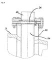
上述の明細書はまた、トレイリアクターの個々の固定触媒床の構造を開示し、例えば、少なくとも1個の触媒活性成形触媒体を含む実際の触媒活性床は、反応ガス混合物流の流動方向において、不活性成形体の床および酸素分子を含むガスの定量添加で被覆され、ガス流に対して内部温度制御を必要とし、このガス流は、水素分子および脱水素化される少なくとも1個の炭化水素を含み、このような固定触媒床に流動し、その後このガス流が固定触媒床(すなわち、実際の触媒活性床を被覆する不活性床(不活性成形体の床))に達する。 The above specification also discloses the structure of the individual fixed catalyst beds of the tray reactor, for example, the actual catalytically active bed comprising at least one catalytically active shaped catalyst body in the flow direction of the reaction gas mixture stream, At least one hydrocarbon to be coated with a fixed addition of a bed of inert shaped bodies and a gas containing oxygen molecules and requiring an internal temperature control for the gas stream, this gas stream being dehydrogenated And flow to such a fixed catalyst bed, after which this gas stream reaches the fixed catalyst bed (ie, the inert bed that covers the actual catalytically active bed (the bed of inert shaped bodies)).
しかし、承認された従来技術は、どのような様式において(すなわち、どのように)酸素分子を含むガス流の定量添加を産業規模で行う(実施する)ことを完全に解決していないままである。 However, the approved prior art remains completely unsolved in any manner (ie how) the quantitative addition of gas streams containing molecular oxygen is performed (implemented) on an industrial scale. .
シャフトの関連固定触媒床方向に流動する水素分子および脱水素化される少なくとも1個の炭化水素を含むガス流に、酸素分子を含むガス流を供給する様式は、内部の実験結果に従うが、種々の理由において産業規模プロセス手法に関連する。 The manner in which the gas stream containing oxygen molecules is supplied to the gas stream containing hydrogen molecules flowing in the direction of the associated fixed catalyst bed of the shaft and at least one hydrocarbon to be dehydrogenated depends on the internal experimental results, Relevant to industrial scale process methods for reasons.
はじめに、局所的に酸素濃度を上昇させ、この場合、酸素分子を含むガスを計量する。好ましくない場合に、これらは、例えば、燃焼可能な(爆発性)ガス混合物を局所的に形成する可能性があり、これは用途の点から望ましくなく、これは、これらの存在期間が長くても短期間であり、局所的に厳しく制限される必要があるためである。さらに、定量添加後に生じる反応ガス混合物は、すでに所望の不均一系触媒の燃焼前に高温である(かつ、不均一系触媒の燃焼の過程においてさらに上昇する)。酸素分子を含む反応ガス混合物が固定触媒床に達する前に、それゆえ、通常、反応ガス混合物内に望ましくない均一なフリーラジカル反応があり(例えば、望ましくない発熱性均一フリーラジカルの部分酸化および/または炭化水素の酸素脱水素化、これらの望ましくない反応により局所的に上昇する反応熱が局所的に温度増加を生じ、その結果、典型的に炭化水素の望ましくない熱分解を増加させる)、これは、標的生成物選択性およびさらに一般に触媒の寿命を低下させる副生成物を広範な帯域で有する。このような標的生成物選択性の低下は、とりわけ、少なくとも1種の標的生成物、少なくとも1個の脱水素化炭化水素を、次に反応させる場合(例えば、不均一性触媒の部分酸化)に有利ではない。固定触媒床内で、このような望ましくないフリーラジカル副反応を実質的に抑制し、なぜなら、大きな内部表面の固定床の電荷がフリーラジカルスカベンジャーとして機能するからである。一般に、このような望ましくないフリーラジカル反応の程度は、利用可能な反応時間とともに指数関数的に増加する。 First, the oxygen concentration is locally increased, and in this case, a gas containing oxygen molecules is measured. If not preferred, they can, for example, locally form a combustible (explosive) gas mixture, which is undesirable from an application point of view, even if their duration is long. This is because it is a short period and needs to be strictly restricted locally. Furthermore, the reaction gas mixture produced after the metered addition is already hot before the desired heterogeneous catalyst combustion (and rises further in the course of the heterogeneous catalyst combustion). Before the reaction gas mixture containing molecular oxygen reaches the fixed catalyst bed, there is therefore usually an undesirable uniform free radical reaction in the reaction gas mixture (for example, partial oxidation of undesirable exothermic homogeneous free radicals and / or Or oxygen dehydrogenation of hydrocarbons, the reaction heat rising locally due to these undesirable reactions will cause a local increase in temperature, resulting in increased undesirable thermal decomposition of the hydrocarbons)) Have a broad range of byproducts that reduce target product selectivity and more generally catalyst life. Such a reduction in target product selectivity is especially true when at least one target product, at least one dehydrogenated hydrocarbon, is then reacted (eg, partial oxidation of a heterogeneous catalyst). It is not advantageous. Within the fixed catalyst bed, such undesirable free radical side reactions are substantially suppressed because the large internal surface fixed bed charge functions as a free radical scavenger. In general, the extent of such undesirable free radical reactions increases exponentially with available reaction time.
このため、触媒活性床を被覆する不活性床にのみ直接に、酸素分子を含むガスの定量添加を直接行うことがすでに提案されている。しかし、このような手法は、酸素分子を含むガスを不活性床に分配させる場合、不活性床の中央供給分配システム(例えば、流出開口部を有する配管系)は、局所的、基本的、無作為に分配された分配抵抗に対応する(どのような方法およびどの程度までかどうかに応じて、不活性成形体が配管系の特定の流出開口部を遮断する)ことが不利である。これは、比較的様々な場合において、局所的に望ましくない様式において、酸素分子を含むガスの供給流を導く。最も好ましくない場合、これは、単位時間当たりの供給量合計に従い制御された酸素分子を含むガスの供給の場合において、いつくかの流出開口部で、流出開口部から流出する酸素分子を含むガスではなく、むしろ、水素分子および流出開口部に入る脱水素化される少なくとも1個の炭化水素を含むガスを導く恐れがある。さらに、不活性成形体は、流出開口部から流出する個々の定量流の流動方向に望ましくない影響を及ぼし、極端な場合、固定触媒床から局所定量流をまさに流す。 For this reason, it has already been proposed to directly add a gas containing oxygen molecules directly to the inert bed covering the catalytically active bed. However, when such a technique distributes gas containing oxygen molecules to the inert bed, the inert bed central supply distribution system (for example, a piping system having an outflow opening) is locally, fundamentally, It is disadvantageous to deal with the distributed resistance that has been distributed in an artificial manner (depending on what method and to what extent, the inert shaped body blocks certain outlet openings in the piping system). This leads to a feed stream of gas containing oxygen molecules in a relatively undesired manner in relatively various cases. In the most unfavorable case, this is the case for a gas containing oxygen molecules flowing out of the outflow opening in some outflow openings in the case of a gas supply containing oxygen molecules controlled according to the total supply per unit time. Rather, it may lead to a gas containing hydrogen molecules and at least one hydrocarbon to be dehydrogenated entering the outlet opening. Furthermore, the inert shaped body has an undesired influence on the flow direction of the individual metered streams flowing out of the outlet opening, and in extreme cases just the local metered stream flows from the fixed catalyst bed.
定量の酸素分子を含む反応ガス混合物が、流動方向において不活性床の上に配置される実際の触媒活性床に入る場合、反応ガス混合物の酸素分子の均一な分配において、触媒活性床の様々な程度の局所触媒燃焼を生じる。これらは、対応する様々な局所的な熱上昇を伴う。通常、局所的に上昇した温度は、触媒活性床の局所的劣化を促進させる。反応ガス混合物の流動方向において、最大限に膨脹させた不活性床を用いて、反応ガス混合物の触媒活性床への入口で酸素分子の基本的に均一な分配を得ることが可能であるが、不活性床の膨張が増加するほど、床を通過する場合の反応ガス混合物の圧低下が増加し、これは、最終的にコンプレッサーの出力増加を伴う。不活性床の反応ガスの滞留時間の増加に伴い、望ましくない副反応もまた、再度生じうる。これは、とりわけ、不活性床の内部表面積を比較的制限する場合である。 When the reaction gas mixture containing a certain amount of oxygen molecules enters the actual catalyst active bed placed on the inert bed in the flow direction, the various distributions of the catalyst active bed in the uniform distribution of oxygen molecules in the reaction gas mixture. Produces a degree of local catalytic combustion. These are accompanied by a corresponding variety of local heat rises. Usually, locally elevated temperatures promote local degradation of the catalytically active bed. In the flow direction of the reaction gas mixture, it is possible to obtain an essentially uniform distribution of oxygen molecules at the inlet of the reaction gas mixture to the catalytic active bed, using an inert bed that is swelled to the maximum extent, As the expansion of the inert bed increases, the pressure drop of the reaction gas mixture as it passes through the bed increases, which is ultimately accompanied by an increase in compressor output. As the residence time of the reaction gas in the inert bed increases, undesirable side reactions can also occur again. This is especially the case when the internal surface area of the inert bed is relatively limited.
それゆえ、本発明の目的は、本明細書の緒言に記載される、非常に包括的および非常に経済的な、すなわち、容易で相対的に複雑でない様式の上述の特徴を考慮し、関連の不活性床の膨張を最小限にすることができる方法を提供することである。米国特許第2584391号の教示は、触媒流動床の方法に関するため、前記の問題を解決することが不可能である。 The object of the present invention is therefore to consider the above-mentioned features in a very comprehensive and very economical, ie easy and relatively uncomplicated manner, as described in the introduction of the present specification. It is to provide a method that can minimize the expansion of the inert bed. Since the teaching of US Pat. No. 2,584,391 relates to a catalyst fluidized bed process, it is impossible to solve the above problems.
同様に、独国特許出願公開第102004024957号の教示は、前記の問題を解決することが不可能である。はじめに、不均一系触媒の酸素脱水素化に関し、この場合、酸素分子を含む反応ガス混合物を触媒活性床に直接供給し、さらに供給システムが不連続である。さらに、それは、製造に対して比較的複雑なチューブバンドルシステムを必要とし、高価なチューブプレートを有する。 Similarly, the teachings of German Offenlegungsschrift 102004024957 are unable to solve the above problems. First, regarding oxygen dehydrogenation of a heterogeneous catalyst, in this case, a reaction gas mixture containing oxygen molecules is directly supplied to the catalyst active bed, and the supply system is discontinuous. Furthermore, it requires a relatively complex tube bundle system for manufacturing and has an expensive tube plate.
国際出願第2004/074222号は、同じく前記の問題を解決するには役に立たない。従って、この明細書では、酸素分子を含むガスおよび脱水素化される少なくとも1個の炭化水素を含むガス流を、互いに厳密に平行な流動制御において流すことが必要であり、これは、比較的複雑な装置を必要とする。さらに、平行な流動結合は、比較的長い混合域を必要とする。 International Application No. 2004/074222 is also useless to solve the above problem. This specification therefore requires that a gas stream comprising oxygen molecules and a gas stream comprising at least one hydrocarbon to be dehydrogenated flow in strict parallel flow control with respect to each other. Requires complex equipment. Furthermore, parallel flow coupling requires a relatively long mixing zone.
同様に、独国特許出願公開第102004003070号は、不均一系触媒の酸素脱水素化に関し、この場合、反応ガス混合物を触媒活性床に直接流すため、前記の問題の解決に寄与することが不可能である。 Similarly, German Offenlegungsschrift 102004003070 relates to the oxygen dehydrogenation of heterogeneous catalysts, in which case the reaction gas mixture flows directly into the catalytically active bed and thus does not contribute to the solution of the above problems. Is possible.
それゆえ、従来技術で解決されなかった問題に提案される解決は、少なくとも1個の脱水素化炭化水素に脱水素化される少なくとも1個の炭化水素の不均一系触媒による部分脱水素化方法であり、この場合、脱水素化される少なくとも1個の炭化水素の不均一系触媒による部分脱水素化のために、酸素分子、水素分子および脱水素化される少なくとも1個の炭化水素を含む反応ガス混合物の流入流全体を固定触媒床に通して流し、この固定触媒床は、所定の横断面を有するシャフトに配置され、反応ガス混合物の流入流の流動方向において、はじめに、不活性成形体の床および反応ガス混合物流の流動方向に流動する触媒活性床を含み、少なくとも1個の成形触媒体を含み、これは、例えば、(反応ガス混合物の流入流の)その流動方向の反応ガス混合物の流入流、少なくともその入口領域において、水素分子と酸素分子の水への燃焼反応および/または炭素酸化物および水が得られる反応ガス混合物の流入流に存在する炭化水素と酸素分子の燃焼反応の活性エネルギーが、少なくとも1個の脱水素化炭化水素に脱水素化される少なくとも1個の炭化水素の脱水素化のものに比べて低下させ、ただし、脱水素化される少なくとも1個の炭化水素の分量(一般に少なくとも1mol%もしくは少なくとも2mol%または少なくとも3mol%または少なくとも4mol%あるいは少なくとも5mol%)を少なくとも1個の脱水素化炭化水素に脱水素化し、反応ガス混合物の流入流は、シャフト内の流入ガス流Iに固定触媒床の上流の合計体積流量V2の酸素分子を含む流入ガスIIを計量することにより得られ、この流入ガス流Iは、水素分子および脱水素化される少なくとも1個の炭化水素を含み、体積流量V1の固定媒床方向にシャフト内を流動し、この場合、流入ガスIIを、流入ガス流IIの流動方向において、固定触媒床の上流に配置される配管系の複数の流出開口部Aから流動する流入ガスII流の形態で、
a)流入ガス流Iの不在を仮定して、流出開口部Aから流出する全ての流入ガスII流の複数個Mの方向は、流入ガス流Iの流動方向と角α90±60°をつくり
b)シャフトの流入ガス流Iの流量Wに対して、固定触媒床からの流出開口部A全ての複数個Mの距離Dは、2・Wを掛けた反応ガス流入混合物(すなわち、反応ガス混合物の流入流を構成するガス混合物)の導入時間J以下であり
c)射影面E内の流入ガス流Iの流動方向に直角の射影面Eへの、流入ガス流Iの流動方向における流出開口部A全ての複数個Mの重心の射影により、流入ガス流Iにより考慮される射影面積の少なくとも75%(好ましくは少なくとも80%、さらに少なくとも85%、または少なくとも90%、有利には少なくとも95%あるいはさらに100%)においてm2≧10で存在する流出開口部重心の数ZAを生じ
d)流出開口部重心の数ZAに対応する流出開口部Aから流出する個々の流入ガスII流(例えば、体積流または質量流)は、50%以下でそれらの数平均(参照基準としての数平均)から偏位し
e)流出開口部の数ZAのうち、1つの流出開口部の重心から(射影面Eに)最も近い流出開口部重心までの距離dは、2√1m2/ZA以下であり、
f)V1:V2比は、≧8である
ように計量する。
Therefore, the proposed solution to the problem not solved by the prior art is a partial dehydrogenation process with a heterogeneous catalyst of at least one hydrocarbon dehydrogenated to at least one dehydrogenated hydrocarbon. In this case comprising oxygen molecules, hydrogen molecules and at least one hydrocarbon to be dehydrogenated for the partial dehydrogenation of the at least one hydrocarbon to be dehydrogenated by a heterogeneous catalyst. The entire inflow of the reaction gas mixture is caused to flow through a fixed catalyst bed, which is arranged on a shaft having a predetermined cross section, and in the flow direction of the inflow of the reaction gas mixture, first, an inert compact. And a catalytically active bed that flows in the flow direction of the reaction gas mixture stream, and includes at least one shaped catalyst body, for example, counteracting its flow direction (of the incoming flow of the reaction gas mixture). Combustion reaction of hydrogen and oxygen molecules into water and / or inflow of reaction gas mixture from which carbon oxides and water are obtained, at least in the inlet region of the gas mixture The active energy of the reaction is reduced compared to that of at least one hydrocarbon dehydrogenated to be dehydrogenated to at least one dehydrogenated hydrocarbon, provided that at least one of the dehydrogenated hydrocarbons is dehydrogenated A hydrocarbon fraction (generally at least 1 mol% or at least 2 mol% or at least 3 mol% or at least 4 mol% or at least 5 mol%) is dehydrogenated to at least one dehydrogenated hydrocarbon, the inflow of the reaction gas mixture is Inflow gas I containing oxygen molecules with a total volumetric flow rate V2 upstream of the fixed catalyst bed. This inflow gas stream I contains hydrogen molecules and at least one hydrocarbon to be dehydrogenated, and flows in the shaft in the direction of the fixed medium bed with a volumetric flow rate V1, in this case, Inflow gas II flows in the form of inflow gas II flowing from the plurality of outflow openings A of the piping system arranged upstream of the fixed catalyst bed in the flow direction of the inflow gas flow II.
a) Assuming the absence of the inflowing gas flow I, the direction of the plurality M of all inflowing gas II flows flowing out from the outflow opening A forms an angle α90 ± 60 ° with the flow direction of the inflowing gas flow I. b ) For the flow rate W of the inflow gas flow I of the shaft, the distance D of the plurality M of all the outflow openings A from the fixed catalyst bed is 2 × W multiplied by the reaction gas inflow mixture (ie, the reaction gas mixture C) Outflow opening A in the flow direction of the inflowing gas flow I to the projection plane E perpendicular to the flow direction of the inflowing gas flow I in the projection surface E Due to the projection of all M centroids, at least 75% (preferably at least 80%, even at least 85%, or at least 90%, advantageously at least 95% or even more of the projected area considered by the incoming gas flow I 100 Individual input gas II stream exiting from m 2 ≧ 10 d resulting number ZA outflow opening centroid present in) the outflow opening A which corresponds to the number ZA of the outflow opening centroid in) (e.g., the volume flow or mass Flow) is less than 50% and deviates from their number average (number average as a reference standard). E) Out of the number of outflow openings ZA, from the center of gravity of one outflow opening (to projection plane E) The distance d to the near outflow opening center of gravity is 2√1 m 2 / ZA or less,
f) Weigh so that the V1: V2 ratio is ≧ 8.
おもに、本発明における方法の流入ガスII(例えば、空気の場合)を、例えば、20℃(外気温)で計量することができる。 Mainly, the inflow gas II (for example in the case of air) of the method according to the invention can be metered, for example, at 20 ° C. (outside temperature).
本発明において適切には(これは、流出開口部A全体でより一様なガス密度を確実にする)、流入ガス流Iと流入ガスIIの温度間の温度差ΔTII 1(大きさ)は、しかし、300℃以下にするものとする。ΔTII 1は、好ましくは250℃以下、より好ましくは200℃以下、有利には150℃以下、特に有利には100℃以下、非常に特に好ましくは75℃以下、非常に特に有利には50℃以下、さらに30℃以下および最も良いのは≦20℃もしくは≦10℃または0℃である。 Suitably in the present invention (this ensures a more uniform gas density across the outflow opening A), the temperature difference ΔT II 1 (magnitude) between the temperature of the inflow gas stream I and the inflow gas II is: However, it shall be 300 degrees C or less. ΔT II 1 is preferably at most 250 ° C., more preferably at most 200 ° C., advantageously at most 150 ° C., particularly preferably at most 100 ° C., very particularly preferably at most 75 ° C., very particularly preferably at 50 ° C. In the following, 30 ° C. or lower and the best is ≦ 20 ° C. or ≦ 10 ° C. or 0 ° C.
2つの温度が同一でない場合、一般に、流入流Iが高温である。 If the two temperatures are not identical, the incoming stream I is generally hot.
上述についてとりわけ、流入流Iが≧350℃(例えば、≧375℃もしくは≧400℃または≧425℃または≧450℃または≧475℃または≧500℃または≧525℃≧550℃あるいは≧600℃)である。一般に、本温度は、≦800℃、多くの場合≦700℃であるだろう。 In particular, the inflow I is ≧ 350 ° C. (eg, ≧ 375 ° C. or ≧ 400 ° C. or ≧ 425 ° C. or ≧ 450 ° C. or ≧ 475 ° C. or ≧ 500 ° C. or ≧ 525 ° C. ≧ 550 ° C. or ≧ 600 ° C.) is there. Generally, this temperature will be ≦ 800 ° C., often ≦ 700 ° C.
本発明における方法のシャフトに配置される固定触媒床は、シャフトリアクターに配置される単一の固定触媒床またはトレイリアクターとして構成されるシャフトリアクターの複数の触媒床の1つであってよい。固定触媒床がシャフトリアクターの反応ガスの流動方向において、1つ目である場合、一般に、反応ガス混合物の流入流は、まだ少しの脱水素化炭化水素も含まないだろう。しかし、本発明における方法の固定触媒床が、反応ガスの流動方向において、この第1固定触媒床に続く固定触媒床である場合、反応ガス混合物の流入流(すなわち、この固定触媒床に流れるガス流)は、通常、少なくとも1個の脱水素化炭化水素のいくつかも含むだろう。本発明における方法の固定触媒床はまた、反応ガスの流動方向において、トレイリアクターの最後の固定触媒床であってよい。 The fixed catalyst bed disposed on the shaft of the process in the present invention may be one of a plurality of catalyst beds of the shaft reactor configured as a single fixed catalyst bed or tray reactor disposed in the shaft reactor. If the fixed catalyst bed is the first in the flow direction of the reaction gas in the shaft reactor, generally the inflow of the reaction gas mixture will still not contain any dehydrogenated hydrocarbons. However, when the fixed catalyst bed of the method of the present invention is a fixed catalyst bed that follows the first fixed catalyst bed in the flow direction of the reaction gas, the inflow of the reaction gas mixture (that is, the gas flowing to the fixed catalyst bed). Stream) will usually also include some of the at least one dehydrogenated hydrocarbon. The fixed catalyst bed of the process according to the invention may also be the last fixed catalyst bed of the tray reactor in the direction of reaction gas flow.
つまり、本発明における方法は、おもに、トレイリアクターに配置される固定触媒床全てに適用されることができる。 That is, the method in the present invention can be applied mainly to all fixed catalyst beds arranged in a tray reactor.
しかし、反応ガスの流動方向において、シャフトリアクターに配置される第1固定触媒床に供給される反応ガス流入混合物は、種々の理由において少なくとも1個の脱水素化炭化水素のいくつかをすでに含むことができる。これは、例えば、国際出願第03/076370号または独国特許出願公開第10211275号に記載の手法において、脱水素化リアクターから流出する生成ガス流を2つの同一組成物に分け、2つのうち1つを脱水素化リアクターに供給される反応ガス混合物に脱水素化循環ガスとして再循環させ、もう1つをさらに別の方法(例えば、反応チャンバーで形成された脱水素化炭化水素の不均一系触媒の部分酸化のために)で使用する場合である。 However, in the flow direction of the reaction gas, the reaction gas inflow mixture fed to the first fixed catalyst bed arranged in the shaft reactor already contains some of the at least one dehydrogenated hydrocarbon for various reasons. Can do. This is done, for example, by dividing the product gas stream exiting the dehydrogenation reactor into two identical compositions in the manner described in WO 03/076370 or DE 10211275. One is recirculated to the reaction gas mixture fed to the dehydrogenation reactor as a dehydrogenation recycle gas, and the other is further processed (eg, a heterogeneous system of dehydrogenated hydrocarbons formed in the reaction chamber). For partial oxidation of the catalyst).
さらに、上述はまた、本発明における方法の酸素分子を含む流入ガスIIと合わせて、固定触媒床に供給される反応ガス混合物の流入流を構成する流入ガス流Iに対応して適応する。 Furthermore, the above also applies correspondingly to the incoming gas stream I which constitutes the incoming stream of the reaction gas mixture fed to the fixed catalyst bed, together with the incoming gas II containing oxygen molecules of the process according to the invention.
本発明における方法の有用な流入ガスIIは、おもに、純粋形態の酸素分子または酸素分子および不活性ガスの混合物(例えば、空気)のどちらかである。例えば、使用されるこのような不活性ガスは、窒素分子、二酸化炭素、希ガスおよび/または水蒸気であってよい。 The useful inflow gas II of the process in the present invention is primarily either pure form of oxygen molecules or a mixture of oxygen molecules and an inert gas (eg, air). For example, such inert gases used can be molecular nitrogen, carbon dioxide, noble gases and / or water vapor.
用途において適切には、流入ガスIIは、空気および水蒸気の混合物であるだろう。流入ガスIIとして酸素分子および不活性ガスの混合物を使用することは、これが流入ガス流Iに流入ガスIIを入れる場合の流出開口部Aの領域の爆発性挙動をより好ましくするという点において、流入ガスIIとして純粋酸素分子の使用以上に有利である。さらに、流入ガスIIの不活性ガスのさらなる使用は、合計体積流量V2をより大きくすることができ、これは、流入ガス流Iに流入ガスIIを計量する安定性(一様性)に有利であることがわかる。しかし、少なくとも1個の炭化水素の不均一系触媒による部分脱水素化の生成ガス流の不活性ガスの成分の増加が望ましくない場合(例えば、これらが次の少なくとも1個の脱水素化炭化水素の使用時に、高いコストで運搬されなければならないバラストであることがわかった場合)、流入ガスIIの成分を最小量にするだろう。 Suitably in the application, the incoming gas II will be a mixture of air and water vapor. The use of a mixture of molecular oxygen and inert gas as inflow gas II makes it more favorable for the explosive behavior of the region of the outflow opening A when it enters the inflow gas stream I. It is advantageous over the use of pure oxygen molecules as gas II. Furthermore, further use of the inert gas of the incoming gas II can make the total volume flow V2 larger, which is advantageous for the stability (uniformity) of metering the incoming gas II into the incoming gas stream I. I know that there is. However, if an increase in the components of the inert gas in the product gas stream of the partial dehydrogenation with a heterogeneous catalyst of at least one hydrocarbon is undesirable (eg, these are the next at least one dehydrogenated hydrocarbon If it is found that this is a ballast that must be transported at high cost), it will minimize the component of incoming gas II.
本発明における方法に適切な流入ガスIIは、例えば、以下の成分を有する:
水蒸気 0〜80体積%
N2 10〜97体積%および
O2 3〜25体積%。
Inflow gas II suitable for the process according to the invention has, for example, the following components:
Water vapor 0-80% by volume
従って、可能な流入ガスIIの成分は、
H2O 15〜80体積%
N2 20〜85体積%および
O2 5〜25体積%
または
H2O 15〜60体積%
N2 20〜80体積%および
O2 5〜20体積%
であってよい。
Therefore, possible inflow gas II components are:
H 2 O 15 to 80 vol%
Or H 2 O 15 to 60 vol%
It may be.
本発明における方法の体積流量V1(Nm3/hにおいて、Nm3は、標準条件下(0℃、1atm)において生じるだろう適当なガス量の体積m3である)対合計体積流量V2(同様に、Nm3/h)の比は、≧8である。それは、好ましくは≧10、より好ましくは≧15および最も好ましくは≧20である。本発明における方法のV1:V2比は、多くの場合さらに≧25もしくは≧30または≧40あるいは≧50である。しかし、一般に、本発明における方法のV1:V2比は、≦500、しばしば≦400または≦300、多くの場合さらに≦200または≦100である。 Volume flow rate V1 of the process according to the present invention (in Nm 3 / h, Nm 3 is the volume m 3 of the appropriate amount of gas that would occur under standard conditions (0 ° C., 1 atm)) versus total volume flow rate V2 (similarly Nm 3 / h) is ≧ 8. It is preferably ≧ 10, more preferably ≧ 15 and most preferably ≧ 20. The V1: V2 ratio of the process according to the invention is often further ≧ 25 or ≧ 30 or ≧ 40 or ≧ 50. In general, however, the V1: V2 ratio of the process according to the invention is ≦ 500, often ≦ 400 or ≦ 300, often even ≦ 200 or ≦ 100.
一般に、本発明における方法の固定触媒床は、反応ガス混合物の流動方向において、不活性材料の被覆層だけでなく、不活性成形体の最終層も有する。これは、例えば、軸式トレイリアクター(axialen Hordenreaktor)の場合、一般に固定触媒床が、多くの場合、メッシュサイズが成形触媒体に比べ大きいガス浸透性グリッド(gasdurchlaessigen Gitterrost)により支持されるためである。 In general, the fixed catalyst bed of the process according to the invention has not only a coating layer of inert material but also a final layer of inert shaped bodies in the direction of flow of the reaction gas mixture. This is because, for example, in the case of an axial tray reactor, the fixed catalyst bed is generally supported by a gas permeable grid, which is often larger in mesh size than the shaped catalyst body. .
本発明における方法のシャフトに配置される固定触媒床が、シャフトリアクターの流入ガス流Iの流動方向において、第1(および適宜、唯一の)固定触媒床である場合、シャフトの体積流量V1とともに流動する流入ガス流Iは、通常、脱水素化される少なくとも1個の炭化水素の不均一系触媒による脱水素化のためにシャフトリアクターに供給される流入ガス流に対応する。一般に、それは、脱水素化される少なくとも1個の炭化水素(例えば、プロパン)≧5体積%を含む。さらに、それは、例えば、
a)N2、
b)N2およびH2O、
c)N2、H2OおよびH2、
d)N2、H2O、CO2およびH2または
e)N2、H2O、CO、CO2およびH2
を含むことができる。
When the fixed catalyst bed disposed on the shaft of the process of the present invention is the first (and optionally only) fixed catalyst bed in the flow direction of the inflow gas stream I of the shaft reactor, it flows together with the volume flow rate V1 of the shaft. The incoming gas stream I typically corresponds to the incoming gas stream supplied to the shaft reactor for dehydrogenation with a heterogeneous catalyst of at least one hydrocarbon to be dehydrogenated. Generally, it comprises at least one hydrocarbon (eg propane) ≧ 5% by volume to be dehydrogenated. In addition, for example,
a) N 2 ,
b) N 2 and H 2 O,
c) N 2 , H 2 O and H 2 ,
d) N 2 , H 2 O, CO 2 and H 2 or e) N 2 , H 2 O, CO, CO 2 and H 2
Can be included.
さらに、酸素分子の限界量をすでに含むことができる。 Furthermore, a limiting amount of oxygen molecules can already be included.
しかし、本発明における方法の固定触媒床が、反応ガスの流動方向において、この第1固定触媒床に続く固定触媒床である場合、通常、流入ガス流Iは、反応ガスの流動方向において、前の固定触媒床から流出する反応ガス混合物に対応し、これは、通常、上述のガスに加えて少なくとも1個の脱水素化炭化水素を含むだろう。一般に、この時、基本的に酸素分子を含むことはないだろう。 However, if the fixed catalyst bed of the process according to the present invention is a fixed catalyst bed following this first fixed catalyst bed in the flow direction of the reaction gas, the incoming gas stream I is usually Corresponding to the reaction gas mixture flowing out of the fixed catalyst bed, which will normally contain at least one dehydrogenated hydrocarbon in addition to the gases described above. Generally, at this time, it will not contain oxygen molecules basically.
本明細書において、全ての流出開口部Aの(およびこれらから流出する個々の流入ガスII流の)複数個Mを、合計体積流量V2流出の合計のちょうど50%以上(好ましくは、ちょうど60または70%以上、より好ましくはちょうど80または90%以上および最も好ましくは100%)が流出するこれらの流出開口部A(およびこれらから流出する個々の流入ガスII流)を意味すると理解し、ただし、全ての個々の流入ガスII流全体のうち、これらから流出する個々の流入ガスII流は、この複数個Mに含まれる個々の流入ガスII流の最大以上を含む。 As used herein, a plurality M of all outlet openings A (and of the individual inlet gas II streams flowing out of them) is taken to be exactly 50% or more (preferably just 60 or 70% or more, more preferably just 80 or 90% or more and most preferably 100%) is understood to mean these outflow openings A (and the individual inflow gas II streams out of them), provided that Out of all the individual inflowing gas II streams, the individual inflowing gas II streams flowing out of them include the maximum of the individual inflowing gas II streams included in the plurality M.
本発明において好ましくは、製造において可能であるという状況で可能な限り、流出開口部Aから流出する個々の流入ガスII流は、同等に大きい。 Preferably, in the present invention, the individual inflowing gas II streams flowing out of the outflow opening A are equally large as long as it is possible in production.
原則として、本発明における方法の流出開口部Aの形状は任意である。つまり、多角形(例えば、三角形、四角形、五角形、六角形など)および丸形(例えば、楕円形または円形)両方の流出開口部Aが可能である。本発明における方法の流出開口部A全ての形状は、(大きさを含めて)一様が好ましい。丸形流出開口部A(「孔」)が本発明において好ましい。本発明における方法の流出開口部Aの最長寸法L(円形流出開口部の場合は径)(すなわち、特定の流出開口部Aの外形上の2点を直接結ぶ最長線)は、≧0.1mm〜≦5cmが有利である。つまり、Lの可能な値は、≧0.2mm〜≦4cmおよび≧0.3mm〜≦3cmまたは≧0.4mm〜≦2cmあるいは≧0.5mm〜≦1cm、多くの場合、≧1mm〜≦5mmである。 In principle, the shape of the outlet opening A of the method according to the invention is arbitrary. That is, both polygonal (eg, triangular, square, pentagonal, hexagonal, etc.) and round (eg, elliptical or circular) outflow openings A are possible. The shape of all outflow openings A of the method according to the present invention is preferably uniform (including size). A round outflow opening A ("hole") is preferred in the present invention. The longest dimension L (the diameter in the case of a circular outflow opening) of the outflow opening A of the method of the present invention (that is, the longest line directly connecting two points on the outer shape of the specific outflow opening A) is ≧ 0.1 mm. ~ ≦ 5 cm is advantageous. That is, possible values for L are ≧ 0.2 mm to ≦ 4 cm and ≧ 0.3 mm to ≦ 3 cm or ≧ 0.4 mm to ≦ 2 cm or ≧ 0.5 mm to ≦ 1 cm, often ≧ 1 mm to ≦ 5 mm It is.
流出開口部Aの(横断)面積は、(π・L2)/2[式中、上述の範囲の値をLに挿入する]の領域が好ましい。 The (transverse) area of the outflow opening A is preferably a region of (π · L 2 ) / 2 [where the value in the above range is inserted into L].
流出開口部A*の最長寸法Lおよび本流出開口部A*の最短寸法Kから形成される比R(すなわち、流出開口部A*の外形上の2点を結ぶ最短線であり、流出開口部A*の重心を通りつながる)、すなわち、R=L:Kが≧5(通常、Rは<5および≧1である)である場合、本流出開口部A*(例えば、流出開口部A*が溝形である場合)は、本発明の全てにおいて、理論的に、一様な実際の円形流出開口部Aの数nにより置き換えられるものとし、これは以下のように算出する:

π=円周囲対円直径の比
U=流出開口部A*の周囲および
F=流出開口部A*の流出表面積]
nが整数でない場合、最も近い整数に切り上げる(1.50およびその類似数の場合、数字を切り上げる)。
Ratio R formed from the longest dimension L of the outflow opening A * and the shortest dimension K of the main outflow opening A * (that is, the shortest line connecting two points on the outer shape of the outflow opening A * , and the outflow opening A * passes through the center of gravity), that is, when R = L: K is ≧ 5 (usually R is <5 and ≧ 1), this outflow opening A * (eg outflow opening A * In all cases of the present invention, it is theoretically assumed to be replaced by a number n of uniform actual circular outflow openings A, which is calculated as follows:
π = ratio of circumference to circle diameter U = around the outflow opening A * and F = outflow surface area of the outflow opening A * ]
If n is not an integer, round up to the nearest integer (for 1.50 and similar numbers, round up the number).
上述の実際の流出開口部Aの径dhを、以下のように算出する:
これらの実際の円形流出開口部Aの重心を直線G上に配置するものとし、その長さは、最長寸法Lに対応し、これは流出開口部A*の重心を通ってつながり、例えば、この重心は、直線Gの長さを2等分にし、少なくとも伸長された直線Gが流出開口部A*の外形を2回切断し、直線Gが、流入流Iの流動方向と直角をつくる。n個の実際の流出開口部の重心は、この直線G上に一様に分配されるものとし、その流出開口部A*の重心がこの分配の中点(重心)を形成する。 The center of gravity of these actual circular outflow openings A shall be arranged on a straight line G, the length of which corresponds to the longest dimension L, which is connected through the center of gravity of the outflow opening A * , for example The center of gravity divides the length of the straight line G into two equal parts, and at least the extended straight line G cuts the outer shape of the outflow opening A * twice, and the straight line G forms a right angle with the flow direction of the inflow flow I. The center of gravity of the n actual outflow openings is uniformly distributed on the straight line G, and the center of gravity of the outflow opening A * forms the midpoint (center of gravity) of the distribution.
流入ガス流Iの「不在を仮定して」という語句は、本発明における方法の流出開口部Aから流出する(個々の)流入ガスII流が流入ガス流Iと結合する場合に方向を変更することを表す。それゆえ、角αを、流入ガス流Iが別の変化しないプロセス条件下において抑制される場合に存在する特定の流出開口部Aから流出する(個々の)流入ガスII流の方向を使用することにより決定する。 The phrase “assuming absence” of the incoming gas stream I changes direction when the (individual) incoming gas II stream exiting the outlet opening A of the method of the present invention combines with the incoming gas stream I. Represents that. Therefore, use the direction of the (individual) incoming gas II stream that exits from the particular outlet opening A that exists when the incoming gas stream I is constrained under another unchanging process condition. Determined by
本発明において有利には、流出開口部A全て(またはこれらから流出する流入ガスII流)の複数個Mにおいて、角αは、90±50°、好ましくは90±40°、より好ましくは90±30°、さらに90±20°、さらにより好ましくは90±10°、よりさらに90±5°および最も良いのは90°である。流出開口部から流出する(個々の)流入ガスII流の方向は、流出セントラルジェット(zentralen Strahl)の方向であるものとする。 Advantageously in the present invention, the angle α is 90 ± 50 °, preferably 90 ± 40 °, more preferably 90 ± in a plurality M of all of the outflow openings A (or inflow gas II flow out of them). 30 °, even 90 ± 20 °, even more preferably 90 ± 10 °, even more 90 ± 5 ° and best is 90 °. The direction of the (individual) inflow gas II flowing out of the outflow opening is assumed to be the direction of the outflow central jet.
本発明において、流出開口部Aは、固定触媒床の上流に配置されるものとする。つまり、流出開口部Aは、不活性成形体により遮断されないものとする。その代りに、流入流Iの流動方向に直角の流出開口部Aの重心から出るジェットは、少なくとも流出開口部Aの2つの(好ましくは少なくとも4つ、より好ましくは少なくとも6つおよび最も好ましくは少なくとも8つ)水力直径dh(dh=4.F/U)のジェット長において、および最も良いのはいくつかのジェット長においていずれかの不活性成形体と適当に接触しないものとする。別に、流出開口部Aを固定触媒床に可能な限り近くに配置する場合、本発明において有利である。 In this invention, the outflow opening A shall be arrange | positioned upstream of a fixed catalyst bed. That is, the outflow opening A is not blocked by the inactive molded body. Instead, there are at least two (preferably at least four, more preferably at least six, and most preferably at least six) outflow openings A that exit from the center of gravity of the outflow opening A perpendicular to the flow direction of the inflow I. 8) In the jet length of hydraulic diameter d h (d h = 4. F / U) and best not to be in proper contact with any of the inert shaped bodies at several jet lengths. Alternatively, it is advantageous in the present invention if the outlet opening A is located as close as possible to the fixed catalyst bed.
本明細書において、固定触媒床から流出開口部Aまでの距離Dは、固定触媒床の不活性被覆床の不活性成形体と接触するいくつかの点と流出開口部の重心を結ぶ最短の直線であるものとする。 In this specification, the distance D from the fixed catalyst bed to the outflow opening A is the shortest straight line connecting several points in contact with the inactive molded body of the inactive coated bed of the fixed catalyst bed and the center of gravity of the outflow opening. Suppose that
本発明において、シャフトの流入ガス流Iの流量W(m/s)(=本体積流により流動される最小の横断面積により分割された流入ガス流Iの体積流量(すなわち、流入ガス流Iにより被覆され、流入ガス流Iが流動する、流入ガス流Iに対して直角の面の面積、ただし、流出開口部Aの重心は、上述の面に存在する))に対して、固定触媒床から流出開口部A全ての複数個Mまでの距離Dは、2・Wを掛けた反応ガス流入混合物の導入時間J(s)以下とする。つまり、流出開口部A全ての複数個Mは、D≦2・W・Jを満たすものとする。 In the present invention, the flow rate W (m / s) of the inflow gas flow I of the shaft (= the volume flow rate of the inflow gas flow I divided by the minimum cross-sectional area flowed by the main volume flow (that is, by the inflow gas flow I) Against the area of the plane perpendicular to the inflow gas stream I, where the inflow gas stream I flows, but where the center of gravity of the outflow opening A lies in the above-mentioned plane)) from the fixed catalyst bed The distance D to the plurality M of all of the outflow openings A is equal to or shorter than the introduction time J (s) of the reaction gas inflow mixture multiplied by 2 · W. That is, the plurality M of all the outflow openings A satisfy D ≦ 2 · W · J.
導入時間Jは、以下を意味すると理解するものとする。 The introduction time J shall be understood to mean:
導入ガス混合物であって、反応ガス混合物の流入流として酸素分子および脱水素化される炭化水素の同量を有し(各場合、体積%)、出発ガス1としての(すなわち、酸素分子および脱水素化される炭化水素以外のガスとして、導入ガス混合物は、窒素分子のみを含む)脱水素化される炭化水素(または窒素分子を有するその混合物)に、空気の形態(または純粋酸素分子あるいは窒素分子を有するその混合物)の出発ガス2としての酸素分子を添加することより得られ、かつ反応ガス混合物の流入流に存在する場合に同温度TRおよび同圧RRである導入ガス混合物が、残る場合、この導入ガス混合物に存在する酸素量(O2)は、時間の関数として減少する。反応ガス混合物の流入流の導入時間Jは、伴う導入ガス混合物の酸素量がその出発量(絶対量として)の70%に低下した範囲内の時間である。
Introducing gas mixture having the same amount of oxygen molecules and hydrocarbons to be dehydrogenated (in each case by volume%) as an inflow of reaction gas mixture, and as starting gas 1 (ie oxygen molecules and dehydration) As a non-hydrocarbon gas, the introduced gas mixture contains only nitrogen molecules) into the hydrocarbon to be dehydrogenated (or its mixture with nitrogen molecules) in the form of air (or pure oxygen molecules or nitrogen). obtained from the addition of oxygen molecules as the starting
導入時間Jの実験的決定は、以下のような簡易な様式において可能である。 The experimental determination of the introduction time J is possible in the following simple manner.
石英ガラスから製造されたY型混合ノズル(チューブ内径:0.6cm;壁厚:1mm;フォーク角=90°;フォークの2つの分岐は、螺旋状に巻かれ、それぞれは、直線2m長を有し、フォークを支持するY型混合ノズルの石英チューブは、0.5m長を有する)をオーブン(例えば、放射オーブンまたは強制空気式オーブン)に入れ、この場合、温度TRに加熱する。出発ガス1をフォークの2つの分岐のうちの1つに入れ、出発ガス2をフォークの2つの分岐のもう一方に供給する。フォークを担持するY型混合ノズルの石英チューブの末端に圧PRで開口する減圧弁を配置する。互いに関連する2つの出発ガスの体積流量は、例えば、所望の導入ガス混合物の組成物がフォークの上に形成される量である。絶対体積流量を、Y型混合ノズルの担体チューブから流出する場合の導入ガス混合物の酸素量がその算出可能な出発量の70%のみであるように調節する。Jを、流量で割った長さの指数として流量およびフォークを担持する石英チューブの長さから算出する。一般に、Y型混合ノズルの担体チューブの導入ガス混合物の体積流量は、<10m3/hである。Y型混合ノズルの担体チューブから流出時の導入ガス混合物流の酸素量をラムダプローブ(λプローブ)により決定することができる。これをNernstプローブとして設計することができる。これは、一方を導入ガス混合物流に暴露し、もう一方を酸素基準物質に暴露するセラミックセンサー要素である。例えば、周囲空気をこのような基準物質として使用することができる。高温TRにて、慣例的に使用されるプローブのイットリウム添加二酸化ジルコニウムセラミックは、マイナス酸素イオンを流すことができる。2つのガスの酸素分子の濃度差がプローブのイオン拡散を生成する。これは、プローブ、プローブ電圧の内外に実装される白金電極間で、電流を抽出することができる。この電圧は、Nernst式により説明でき、Y型混合ノズルの担体チューブから流出時の導入ガス混合物流の酸素量を直接測定する。
Y-type mixing nozzle manufactured from quartz glass (tube inner diameter: 0.6 cm; wall thickness: 1 mm; fork angle = 90 °; the two branches of the fork are spirally wound, each having a straight line length of 2 m and, a quartz tube Y-type mixing nozzle supporting the fork, placed with a 0.5m length) in an oven (e.g., radiation oven or forced air oven), this case is heated to a temperature T R. Starting gas 1 is placed in one of the two branches of the fork and starting
別法として、ラムダ抵抗プローブを使用することができる。本明細書において、一般にセンサー要素は、半導体の二酸化チタンセラミックからなる。酸素欠乏により電荷担体を得、これは供与体として作用する。周囲酸素で欠乏部位を占め、遊離電荷担体数を減少させる。本明細書において、酸素イオンは、伝導率に実質的に寄与しないがむしろ、酸素は、遊離電荷担体の数を減少させる。高濃度の酸素で、センサー材料は、高い抵抗率を有する。固定抵抗を有する電圧分割器により、信号を生成する。 Alternatively, a lambda resistance probe can be used. In this specification, the sensor element is generally composed of a semiconductor titanium dioxide ceramic. Oxygen deficiency yields a charge carrier that acts as a donor. Oxygen occupies the deficient site and reduces the number of free charge carriers. Herein, oxygen ions do not substantially contribute to conductivity, but rather oxygen reduces the number of free charge carriers. At high concentrations of oxygen, the sensor material has a high resistivity. A signal is generated by a voltage divider having a fixed resistance.
ラムダプローブの製造業者は、例えば、Robert Bosch GmbHおよびさらにDensoならびにNGKである。 Manufacturers of lambda probes are, for example, Robert Bosch GmbH and also Denso and NGK.
本明細書において、流出開口部の重心は、(均一な質量充填において)流出開口部の質量の理論的重心を意味すると理解するものとする。 In this specification, the center of gravity of the outflow opening shall be understood to mean the theoretical center of mass of the outflow opening (in uniform mass filling).
本発明において好ましくは、条件D≦1・W・J、さらにD≦0.5・W・Jが流出開口部A全ての複数個Mを満たすものとする。最も好ましくは、条件D≦0.2・W・Jが流出開口部A全ての複数個に妥当であるものとする。条件D≦0.05・W・Jが流出開口部A全ての複数個Mを満たす場合がさらに良い。非常に特に有利には、流出開口部A全ては、通常、関連条件を満たす。さらに、本発明において、流出開口部A全てがDにおいて一様な値を有する場合が好ましい。 In the present invention, it is preferable that the condition D ≦ 1 · W · J and further D ≦ 0.5 · W · J satisfy a plurality M of all the outflow openings A. Most preferably, the condition D ≦ 0.2 · W · J is valid for a plurality of all of the outflow openings A. It is even better when the condition D ≦ 0.05 · W · J satisfies a plurality M of all the outflow openings A. Very particularly advantageously, all the outlet openings A usually fulfill the relevant conditions. Furthermore, in the present invention, it is preferable that all the outflow openings A have a uniform value in D.
しかし、全ての流出開口部Aは、Dにおいて一様な値を必ずしも必要としない。 However, all outflow openings A do not necessarily require a uniform value in D.
しかし、流入ガス流Iの流動方向において、全ての流出開口部Aの複数個Mの重心を、流入ガス流Iの流動方向に直角に射影面Eに射影する場合、m2で存在する流出開口部重心の数ZAは、本発明において、射影面E内の流入ガス流Iにより被覆される射影表面積の少なくとも75%において、≧10でなければならない(好ましくは少なくとも80%、さらに少なくとも85%、よりさらに少なくとも90%、好ましくは少なくとも95%およびより好ましくは100%)。本発明において有利には、上述のZAがZA≧20または≧30、好ましくは≧40または≧50、より好ましくは≧60または≧70、最も好ましくは≧80または≧90あるいは≧100である。本発明において有利には、ZAを大きくなるよう選択する(一般に、ZAの増加は、流出開口部Aの最長寸法Lを減少させる)。おもに、本発明における方法のZAは、100000以上であってよい。しかし、経済的に実行可能な製造のため、一般に、ZAは、通常、≦10000、多くの場合≦1000である。 However, in the flow direction of the inflowing gas flow I, when the center of gravity of a plurality M of all the outflow openings A is projected onto the projection plane E perpendicular to the flow direction of the inflowing gas flow I, the outflow opening existing at m 2. The number ZA of the center of gravity has to be ≧ 10 in the present invention in at least 75% of the projected surface area covered by the incoming gas flow I in the projection plane E (preferably at least 80%, more preferably at least 85%, And still more at least 90%, preferably at least 95% and more preferably 100%). Advantageously according to the invention, the ZA mentioned above is ZA ≧ 20 or ≧ 30, preferably ≧ 40 or ≧ 50, more preferably ≧ 60 or ≧ 70, most preferably ≧ 80 or ≧ 90 or ≧ 100. In the present invention, ZA is advantageously chosen to be large (in general, increasing ZA reduces the longest dimension L of outflow opening A). Mainly, the ZA of the method in the present invention may be 100,000 or more. However, for economically viable production, ZA is generally ≦ 10000, often ≦ 1000.
流出開口部の数ZAのうち、(射影面Eにおいて)1つの流出開口部重心から最も近い流出開口部重心までの距離dは、2√1m2/ZA以下とする。 Of the number ZA of outflow openings, the distance d from one outflow opening centroid to the nearest outflow opening centroid (in the projection plane E) is 2√1 m 2 / ZA or less.
つまり、本発明において、dは1.75√1m2/ZA以下または1.5√1m2/ZA以下あるいは1.25√1m2/ZA以下となりうる。 That is, in the present invention, d can be 1.75√1 m 2 / ZA or less, 1.5√1 m 2 / ZA or less, or 1.25√1 m 2 / ZA or less.
当然ながら、流出開口部重心の数ZAもまた、射影面Eにおける流入ガス流Iにより被覆される射影表面積全体に一様に(d=√1m2/ZA)分配することができる。 Of course, the number ZA of the outflow opening centroids can also be distributed uniformly (d = √1 m 2 / ZA) over the entire projected surface area covered by the inflowing gas flow I at the projection plane E.
さらに、本発明において、これらの流出開口部Aから流出する流入ガスII流が互いに対抗する流出開口部は、互いに対面しない場合が好ましい。 Furthermore, in the present invention, it is preferable that the outflow openings that the inflow gas II flows out from the outflow openings A oppose each other do not face each other.
さらに本発明において、流出開口部重心の数ZAに対応する流出開口部Aから流出する個々の流入ガスII(例えば、体積または質量)流が、これらの数平均(数ZA全体の平均)から50%以下(好ましくは40%以下、より好ましくは30%以下、さらにより好ましくは20%以下または10%以下、さらに5%以下および最も良いのは全くない)で偏位することが不可欠である。数平均は、参照基準である。 Furthermore, in the present invention, the individual inflowing gas II (for example, volume or mass) flow flowing out from the outflow opening A corresponding to the number ZA of the outflow opening center of gravity is 50 to 50 from these number averages (average of the whole number ZA). It is essential to deviate by% or less (preferably 40% or less, more preferably 30% or less, even more preferably 20% or less or 10% or less, even 5% or less and none at all). Number average is a reference standard.
本発明において有利には、本発明における方法のシャフトが(非偏位)直列シリンダー形状(平行な面内に位置し、2つの基部表面上に平行に、垂直な線により点を結ぶ、2つの一致の(合同の)基部表面)を有する。シリンダー形状内で、楕円形シリンダーおよび特に円形シリンダーが好ましい。 Advantageously, in the present invention, the shaft of the method according to the present invention has two (non-displaced) in-line cylinder shapes (located in parallel planes, parallel on two base surfaces, and connected by two vertical lines. With a congruent (congruent) base surface). Within the cylinder shape, elliptical cylinders and especially circular cylinders are preferred.
当然ながら、本発明における方法はまた、本発明の固定触媒床の上流の酸素分子を含むガスの注入に加えて、不活性被覆床に酸素分子を含むガスの定量添加を行うものを使用する。 Of course, the method of the present invention also uses a method in which, in addition to the injection of gas containing oxygen molecules upstream of the fixed catalyst bed of the present invention, a fixed amount of gas containing oxygen molecules is added to the inert coating bed.
さらなる本発明の要件は、固定触媒床を通る反応ガス混合物の流入流のシングルパスに対して、1分量、一般に反応ガス混合物の流入流に存在する脱水素化される少なくとも1個の炭化水素の少なくとも1mol%もしくは少なくとも2mol%または少なくとも3mol%または少なくとも4mol%あるいは少なくとも5mol%(好ましくは少なくとも7mol%、より好ましくは少なくとも9mol%および最も好ましくは少なくとも11mol%)を少なくとも1個の脱水素化炭化水素に脱水素化する。しかし、上述のモル%は、通常、≦20mol%である。 A further requirement of the present invention is that for a single pass of the reactant gas mixture inflow through the fixed catalyst bed, the amount of at least one hydrocarbon to be dehydrogenated, generally present in the influent of the reactant gas mixture, is one minute. At least 1 mol% or at least 2 mol% or at least 3 mol% or at least 4 mol% or at least 5 mol% (preferably at least 7 mol%, more preferably at least 9 mol% and most preferably at least 11 mol%) of at least one dehydrogenated hydrocarbon To dehydrogenate. However, the above mol% is usually ≦ 20 mol%.
一般に、反応ガス混合物の流入流は、一般に、脱水素化される少なくとも1個の炭化水素少なくとも5体積%を含むだろう。多くの場合、この体積分率は、同基準値≧10体積%、多くの場合、≧15体積%および通常≧20体積%または≧25体積%あるいは≧30体積%である。しかし一般に、この体積分率は、同基準値≦90体積%、通常、≦80体積%および多くの場合、≦70体積%である。上記は、とりわけ、脱水素化される炭化水素としてのプロパンおよび脱水素化炭化水素としてのプロピレンの場合に(同様に本明細書の他の記載全てに)適用される。当然ながら、これらはまた、イソブタンが脱水素化される炭化水素であり、イソブテンが脱水素化炭化水素である場合も適用される。 Generally, the incoming stream of the reaction gas mixture will generally contain at least 5% by volume of at least one hydrocarbon to be dehydrogenated. In many cases, this volume fraction is the same reference value ≧ 10% by volume, often ≧ 15% by volume and usually ≧ 20% or ≧ 25% or ≧ 30% by volume. In general, however, the volume fraction is ≦ 90% by volume, usually ≦ 80% by volume and often ≦ 70% by volume. The above applies in particular in the case of propane as the hydrocarbon to be dehydrogenated and propylene as the dehydrogenated hydrocarbon (also to all other descriptions herein). Of course, these also apply when isobutane is the hydrocarbon to be dehydrogenated and isobutene is the dehydrogenated hydrocarbon.
一般に、本発明における方法の流入ガス流Iに計量される流入ガスIIの量は、例えば、存在する脱水素化される炭化水素および脱水素化炭化水素の量(例えば、プロパンおよびプロピレン)に対して、得られる反応ガス流入混合物が酸素分子0.01または0.5〜30体積%を含むなどだろう。 In general, the amount of influent gas II metered into the influent gas stream I of the process according to the invention is, for example, relative to the amount of hydrocarbons to be dehydrogenated and dehydrogenated hydrocarbons (eg propane and propylene). Thus, the resulting reaction gas influent mixture will contain 0.01 or 0.5 to 30% by volume of oxygen molecules.
本発明において適切には、反応ガス混合物の流入流の酸素分子のモル量は、本明細書に存在する水素分子のモル量の50%以下である。 Suitably in the present invention, the molar amount of molecular oxygen in the incoming stream of the reaction gas mixture is no more than 50% of the molar amount of molecular hydrogen present herein.
一般に、本明細書に存在する水素分子のモル量に対して、反応ガス混合物の流入流の酸素分子のモル量は、10〜40mol%、しばしば15〜35mol%および多くの場合20〜30mol%である。 In general, the molar amount of oxygen molecules in the incoming stream of the reaction gas mixture is 10-40 mol%, often 15-35 mol% and often 20-30 mol%, relative to the molar amount of hydrogen molecules present herein. is there.
本発明において有利には、本発明における方法において、反応ガス混合物の流入流に存在する酸素分子全体(または少なくとも95mol%)は、反応ガス混合物の流入流に存在する水素分子消費のために反応ガス混合物の流入流が固定触媒床を通過する場合に消費される。 Advantageously in the present invention, in the process according to the present invention, the total oxygen molecules (or at least 95 mol%) present in the inflow of the reaction gas mixture are reacted with the reaction gas due to the consumption of hydrogen molecules present in the inflow of the reaction gas mixture. It is consumed when the incoming stream of the mixture passes through the fixed catalyst bed.
本発明における方法の用途の点から適切には、トレイリアクターの場合、流動される固定触媒床に事前に形成された水素分子量の約半分を、反応ガス混合物の流入流が固定触媒床を通過する場合に酸素分子を用いて燃焼する。 Appropriately from the point of application of the process in the present invention, in the case of a tray reactor, about half of the molecular weight of hydrogen previously formed in the fluidized fixed catalyst bed, the inflow of the reaction gas mixture passes through the fixed catalyst bed. In some cases, it burns using oxygen molecules.
本発明における方法の固定触媒床に入る場合の反応ガス混合物の流入流の初期圧は、一般に、1.5〜6bar、しばしば2〜5barおよび多くの場合3〜4barである。 The initial pressure of the incoming stream of the reaction gas mixture as it enters the fixed catalyst bed of the process according to the invention is generally from 1.5 to 6 bar, often from 2 to 5 bar and often from 3 to 4 bar.
本発明における方法の固定触媒床に入る場合の反応ガス混合物の流入流の温度は、一般に、300〜700℃、しばしば350〜600℃および多くの場合400〜500℃である。 The temperature of the incoming stream of the reaction gas mixture as it enters the fixed catalyst bed of the process according to the invention is generally from 300 to 700 ° C., often from 350 to 600 ° C. and often from 400 to 500 ° C.
本明細書において、反応ガスで反応ステップを触媒する固定触媒床の負荷は、ごく一般に標準リットル(=Nl;適当な反応ガス量が標準条件(0℃、1atm)下において生じるリットルの体積)の反応ガス量であり、これを、時間当たり固定触媒床1リットルに通して流すことを意味すると理解するものとする。しかし、負荷は、反応ガスの1構成物質のみを基準とすることもできる。 In this specification, the loading of the fixed catalyst bed that catalyzes the reaction step with the reaction gas is generally in standard liters (= Nl; the volume of liters where an appropriate amount of reaction gas occurs under standard conditions (0 ° C., 1 atm)). It is to be understood that this is the amount of reaction gas, which means flowing through 1 liter of fixed catalyst bed per hour. However, the load can be based on only one constituent of the reaction gas.
その場合、それは、Nl/l・hのこの構成物質量であり、これを、時間当たりの固定触媒床1リットルに通して流す(純粋不活性材料床は、固定触媒床に計数されない)。負荷は、固定触媒床に存在する触媒量のみを基準とすることもでき、これは、不活性材料で希釈された実際の触媒を含む(明白に後述する)。 In that case, it is this constituent quantity of Nl / l · h, which flows through 1 liter of fixed catalyst bed per hour (pure inert material bed is not counted in the fixed catalyst bed). The load can also be based solely on the amount of catalyst present in the fixed catalyst bed, which includes the actual catalyst diluted with inert material (discussed explicitly below).
おもに、本発明における方法は、(本明細書に存在する触媒の合計量に対して)固定触媒床の負荷量で実施することができ、反応ガスおよび本明細書に存在する脱水素化される少なくとも1個の炭化水素(例えば、プロパン)ともに100〜10000h-1(Nl/l・h、略語h-1)、しばしば300〜5000h-1、すなわち、多くの場合500〜3000h-1(実質的に脱水素化される少なくとも1個の炭化水素の所望の変換に関連しない)である。 In principal, the process in the present invention can be carried out with a fixed catalyst bed loading (relative to the total amount of catalyst present herein) and is dehydrogenated as present in the reaction gas and herein. at least one hydrocarbon (e.g., propane) both 100~10000h -1 (Nl / l · h , the abbreviation h -1), often 300~5000H -1, i.e., often 500~3000H -1 (substantially Is not related to the desired conversion of at least one hydrocarbon to be dehydrogenated).
一般に、本発明の方法において、流入ガス流Iは、シャフトに配置される固定触媒床方向に基本的に垂直に流動する。つまり、シャフトの流入ガス流Iの流動方向と固定触媒床の流動表面に配列される面との間につくる角βは、通常、90±30°、好ましくは90±20°、より好ましくは90±10°、さらにより好ましくは90±5°および最も良いのは90°である。 In general, in the process of the invention, the incoming gas stream I flows essentially perpendicular to the direction of the fixed catalyst bed arranged on the shaft. That is, the angle β formed between the flow direction of the inflow gas flow I of the shaft and the surface arranged on the flow surface of the fixed catalyst bed is usually 90 ± 30 °, preferably 90 ± 20 °, more preferably 90 ± 10 °, even more preferably 90 ± 5 ° and best is 90 °.
通常、本発明における方法のシャフトの固定触媒床の流動表面積は、≧1m2、多くの場合さらに≧2m2もしくは≧3m2または≧4m2あるいは≧5m2である。当然ながら、上述の流動表面積はまた、≧10m2もしくは≧20m2または≧30m2であってよい。世界規模の工場において、上述の流動表面積は、≧40m2または≧50m2であってもよい。通常、当該流動表面積≧100m2は、例外である。 Usually, the fluidized surface area of the fixed catalyst bed of the shaft of the process according to the invention is ≧ 1 m 2 , in many cases ≧ 2 m 2 or ≧ 3 m 2 or ≧ 4 m 2 or ≧ 5 m 2 . Of course, the flow surface area described above may also be ≧ 10 m 2 or ≧ 20 m 2 or ≧ 30 m 2 . In a global scale factory, the fluid surface area described above may be ≧ 40 m 2 or ≧ 50 m 2 . Usually, the flow surface area ≧ 100 m 2 is an exception.
触媒活性床に有用な触媒は、おもに、不均一系触媒による脱水素化の従来技術において公知の脱水素化触媒全てである。これらは、大きく2群に分けることができ、具体的に、酸化特性のもの(例えば、酸化クロムおよび/または酸化アルミニウム)および一般的な酸化支持体(例えば、二酸化ジルコニウム、酸化アルミニウム、二酸化ケイ素、二酸化チタン、酸化マグネシウム、酸化ランタンおよび/または酸化セリウム)に堆積する少なくとも1個の一般的に比較的な貴金属(例えば、白金)からなるものである。従って使用することができる脱水素化触媒は、国際出願第01/96270号、欧州特許出願公開第731077号、独国特許出願公開第10211275号、独国特許出願公開第10131297号、国際出願第99/46039号、米国特許第4788371号、欧州特許出願公開第705136号、国際出願第99/29420号、米国特許第4220091号、米国特許第5430220号、米国特許第5877369号、欧州特許出願公開第117146号、独国特許出願公開第19937196号、独国特許出願公開第19937105号、米国特許第3670044号、米国特許第6566573号および国際出願第94/29021号に推奨されるものを含む。本発明における方法のこれらの触媒は、最初に記載の理由において、本発明における方法の触媒活性床の単一の触媒であってよい。おもに、触媒活性床は、触媒活性成形体のみから構成することができる。当然ながら、触媒活性床もまた、不活性成形体で希釈された触媒活性成形体からなることができる。このような不活性成形体は、例えば、焼成粘土(ケイ酸アルミニウム)またはステアタイト(例えば、CeramTec製C220)あるいは他の高温セラミック材料(好ましくは実質的に孔がない)、例えば酸化アルミニウム、二酸化ケイ素、二酸化チタン、酸化マグネシウム、酸化ランタン、酸化セリウム、亜鉛アルミニウム混合酸化物、二酸化トリウム、二酸化ジルコニウム、ケイ素炭化物または他のケイ酸、例えば、ケイ酸マグネシウムおよび上述の材料の混合物から製造することができる。上述の材料はまた、不活性被覆床および適宜、本発明における方法の固定触媒床の最終床に有用である。 Useful catalysts for the catalytically active bed are mainly all dehydrogenation catalysts known in the prior art of dehydrogenation with heterogeneous catalysts. These can be broadly divided into two groups, specifically those with oxidation characteristics (eg chromium oxide and / or aluminum oxide) and general oxidation supports (eg zirconium dioxide, aluminum oxide, silicon dioxide, It consists of at least one generally comparative noble metal (eg platinum) deposited on titanium dioxide, magnesium oxide, lanthanum oxide and / or cerium oxide). Thus, dehydrogenation catalysts which can be used are: International Application No. 01/96270, European Patent Application Publication No. 731077, German Patent Application Publication No. 10211275, German Patent Application Publication No. 10112297, International Application No. 99. No./46039, US Pat. No. 4,788,371, European Patent Application Publication No. 705136, International Application No. 99/29420, US Pat. No. 4220091, US Pat. No. 5,430,220, US Pat. No. 5,877,369, European Patent Application Publication No. 117146. No. 1, German Patent Application Publication No. 1937196, German Patent Application Publication No. 19937105, US Pat. No. 3670044, US Pat. No. 6,656,573 and International Application No. 94/29021. These catalysts of the process according to the invention may be a single catalyst of the catalytically active bed of the process according to the invention for the reasons described at the outset. Mainly, the catalytically active bed can be composed only of the catalytically active shaped body. Of course, the catalytically active bed can also consist of a catalytically active shaped body diluted with an inert shaped body. Such inert shaped bodies can be, for example, calcined clay (aluminum silicate) or steatite (eg C220 from CeramTec) or other high temperature ceramic materials (preferably substantially free of pores) such as aluminum oxide, Can be produced from silicon, titanium dioxide, magnesium oxide, lanthanum oxide, cerium oxide, zinc aluminum mixed oxide, thorium dioxide, zirconium dioxide, silicon carbide or other silicic acids, eg magnesium silicate and mixtures of the above mentioned materials it can. The materials described above are also useful for the inert coated bed and, optionally, the final bed of the fixed catalyst bed of the process in the present invention.
有利なことに、本発明における方法の固定触媒床の不活性被覆床は、例えば、本不活性床を通り流動する場合の反応ガス混合物の流入流において、本明細書に存在する酸素分子≦35mol%(好ましくは≦30mol%、より好ましくは≦25mol%、さらに≦20mol%、特に有利には≦15mol%、さらに≦10mol%および最も好ましくは≦5mol%または0mol%)を変換するなどを必要とする。 Advantageously, the inert catalyst bed of the fixed catalyst bed of the process according to the invention is, for example, an oxygen molecule present herein ≦ 35 mol in the incoming stream of the reaction gas mixture as it flows through the inert bed. % (Preferably ≦ 30 mol%, more preferably ≦ 25 mol%, further ≦ 20 mol%, particularly advantageously ≦ 15 mol%, further ≦ 10 mol% and most preferably ≦ 5 mol% or 0 mol%), etc. To do.
特に、本発明における方法の固定触媒床の触媒活性床における(例えば、単一)触媒として使用される触媒は、独国特許出願公開第19937107号の実施例1、実施例2、実施例3および実施例4におけるものであってよい。 In particular, the catalysts used as the (for example, single) catalyst in the catalytically active bed of the fixed catalyst bed of the process according to the invention are the examples 1, 2, 3 and 3 of DE 199 37 107. It may be as in Example 4.
これらは、脱水素化触媒であり、二酸化ジルコニウム10〜99.9質量%、酸化アルミニウム、二酸化ケイ素および/または二酸化チタン0〜60質量%、元素の周期表の少なくとも1個の第1または第2主属元素、第3遷移元素、第8遷移元素、ランタンおよび/またはスズ0.1〜10質量%を含み、ただし、質量%の合計を100質量%まで追加する。 These are dehydrogenation catalysts, 10 to 99.9% by weight of zirconium dioxide, 0 to 60% by weight of aluminum oxide, silicon dioxide and / or titanium dioxide, at least one first or second of the periodic table of elements. The main group element, the third transition element, the eighth transition element, lanthanum and / or tin is contained in an amount of 0.1 to 10% by mass, provided that the total of the mass% is added to 100% by mass.
好ましい実施形態において、上述の脱水素化触媒は、少なくとも1個の第VIII遷移元素、少なくとも1個の第IおよびII主属元素、少なくとも1個の第IIIおよび/または第IV主属元素およびランタニドおよびアクチニドを含む少なくとも1個の第III遷移元素を含む。第VIII遷移元素として、脱水素化触媒の活性組成物は、好ましくは白金および/またはパラジウム、より好ましくは白金を含む。第IおよびII主属元素として、上述の脱水素化触媒の活性組成物は、好ましくはカリウムおよび/またはセシウムを含む。ランタニドおよびアクチニドを含む第III遷移元素として、上述の脱水素化触媒の活性組成物は、好ましくはランタンおよび/またはセリウムを含む。第IIIおよび/または第IV主属元素として、上述の脱水素化触媒の活性組成物は、好ましくはホウ素、ガリウム、ケイ素、ゲルマニウム、スズおよび鉛からなる群から選択される1個または複数個の元素、より好ましくはスズを含む。最も好ましくは、上述の脱水素化触媒の活性組成物は、各場合、少なくとも1個の上述の元素の代表例を含む。 In a preferred embodiment, the dehydrogenation catalyst described above comprises at least one VIII transition element, at least one primary I and II main element, at least one III and / or IV main element and a lanthanide. And at least one III transition element including actinides. As the VIII transition element, the active composition of the dehydrogenation catalyst preferably comprises platinum and / or palladium, more preferably platinum. As the main group I and II elements, the above-mentioned dehydrogenation catalyst active composition preferably contains potassium and / or cesium. As a III transition element comprising lanthanides and actinides, the above-mentioned active composition of the dehydrogenation catalyst preferably comprises lanthanum and / or cerium. As the III and / or IV main group element, the dehydrogenation catalyst active composition is preferably one or more selected from the group consisting of boron, gallium, silicon, germanium, tin and lead. It contains elements, more preferably tin. Most preferably, the dehydrogenation catalyst active composition described above comprises in each case a representative example of at least one of the elements described above.
一般に、脱水素化触媒は、触媒成形物(一般的に径0.1または1〜10mm、好ましくは1.5〜5mm、典型的な長さ1〜20mm、好ましくは3〜10mm)、錠剤(好ましくは成形物と同じ寸法)および/または触媒リング(Katalysatorringe)(外径および典型的な長さ2〜30mmまたは〜10mm、壁厚1〜10mmまたは〜5mmあるいは〜3mm)であってよい。
In general, the dehydrogenation catalyst is a catalyst molding (generally 0.1 or 1 to 10 mm in diameter, preferably 1.5 to 5 mm,
おもに、触媒の形状(とりわけ、支持触媒の場合)に関して、または不活性成形体の形状に関してのどちらも制限はない。特に一般的な形状は、固体シリンダー、中空シリンダー(リング)、球、円錐、角錐および立方体およびさらに成形物、ワゴンホイール型(Wagenraeder)、星型およびモノリス型である。 There is primarily no limitation either on the shape of the catalyst (especially in the case of supported catalysts) or on the shape of the inert shaped body. Particularly common shapes are solid cylinders, hollow cylinders (rings), spheres, cones, pyramids and cubes and further moldings, wagon wheels, stars and monoliths.
成形触媒体および不活性成形体の最長寸法(成形体表面における2点を結ぶ最長の直線)は、0.5mm〜100mm、しばしば、1.5mm〜80mmおよび多くの場合3mm〜50mmまたは〜20mmであってよい。 The longest dimension of the molded catalyst body and the inert molded body (the longest straight line connecting two points on the surface of the molded body) is 0.5 mm to 100 mm, often 1.5 mm to 80 mm and often 3 mm to 50 mm or 20 mm. It may be.
最終的に、独国出願第102005044916号の触媒もまた、本発明における方法の固定触媒床の触媒活性床に特に適切な触媒(例えば、単一の触媒)として引用するものとする。 Finally, the catalyst of DE 102005044916 is also cited as a catalyst particularly suitable for the catalytically active bed of the fixed catalyst bed of the process according to the invention (for example a single catalyst).
本発明における方法に関して、触媒表面に堆積し、触媒を非活性化する炭素を含めた高沸点高分子量の有機化合物を取り出すことができ、高温にて酸素を含むガスとともに時々固定触媒床を流動し、従って堆積した物質を効果的に燃焼させることにより、触媒を再生することができる。 With respect to the method of the present invention, high boiling high molecular weight organic compounds, including carbon that deposits on the catalyst surface and deactivates the catalyst, can be removed and occasionally flow through the fixed catalyst bed with oxygen-containing gas at high temperatures. Thus, the catalyst can be regenerated by effectively burning the deposited material.
長時間の作業後、本明細書において推奨される触媒を、通常、簡易な様式において、例えば、はじめに第1再生ステージにおいて、入口温度300〜600℃(極端な場合、適宜、さらに750℃以下)、多くの場合400〜450℃にて固定触媒床を通る窒素および/または水蒸気で(好ましくは)希釈された空気を通すことにより再生することができる。再生ガスを負荷する触媒は、(再生された触媒の合計量に対して)例えば、50〜10000h-1および再生ガス酸素量0.5〜20体積%であってよい。 After a long period of work, the catalyst recommended herein is usually prepared in a simple manner, for example, first in the first regeneration stage, with an inlet temperature of 300-600 ° C. Often regenerated by passing air diluted (preferably) with nitrogen and / or steam through a fixed catalyst bed at 400-450 ° C. The catalyst loaded with regeneration gas may be, for example, 50-10000 h −1 and regeneration gas oxygen content 0.5-20% by volume (relative to the total amount of regenerated catalyst).
続くさらなる再生ステージにおいて、別の同一再生条件下において使用される再生ガスは、空気であってよい。用途の点から適切には、再生する前に不活性ガス(例えば、N2、例えばO2、H2Oまたはその混合物1体積%以下の産業用窒素)で触媒をパージすることを推奨する。 In the subsequent further regeneration stage, the regeneration gas used under another identical regeneration condition may be air. Appropriately from an application point of view, it is recommended to purge the catalyst with an inert gas (eg N 2 , eg O 2 , H 2 O or a mixture of industrial nitrogen up to 1% by volume of industrial nitrogen) before regeneration.
続いて、一般に、別の同一条件下において純粋水素分子または不活性ガス(好ましくは水蒸気および/または窒素)(水素量は≧1体積%とするものとする)により希釈された水素分子で再生することが好ましい。 Subsequently, it is generally regenerated with hydrogen molecules diluted with pure hydrogen molecules or inert gas (preferably water vapor and / or nitrogen) (the amount of hydrogen shall be ≧ 1% by volume) under different identical conditions. It is preferable.
本発明において、(反応ガス混合物の流入流の流動方向において)固定触媒床の不活性被覆層の床の長さXと射影面Eの距離dの比、すなわち、X:dは、≧0.05、好ましくは≧0.07および特に有利には≧0.1である。多くの場合、本発明における方法の上述のX:d比は、≧0.2もしくは≧0.3または≧0.5あるいは≧1であるだろう。通常、本発明における方法のX:d比は、しかし、通常、≦10および多くの場合≦5である。 In the present invention, the ratio of the bed length X of the inert coating layer of the fixed catalyst bed to the distance d of the projection plane E (in the flow direction of the inflow of the reaction gas mixture), that is, X: d is ≧ 0. 05, preferably ≧ 0.07 and particularly advantageously ≧ 0.1. In many cases, the above-mentioned X: d ratio of the method according to the invention will be ≧ 0.2 or ≧ 0.3 or ≧ 0.5 or ≧ 1. Usually, the X: d ratio of the process according to the invention is usually ≦ 10 and in many cases ≦ 5.
本発明における方法において、流動方向において、不活性床の上に配置された固定触媒床の実際の触媒活性床に反応ガス混合物を入れる場合、反応ガス混合物の酸素分子の分配は、非常に均一であることが好ましい。反応ガス混合物の酸素分子の局所的に最も高い体積濃度と酸素分子の局所的に最も小さい体積濃度間の差は、実際の触媒活性床に反応ガス混合物を入れる場合の反応ガス混合物の酸素分子の平均体積濃度に対して、好ましくは200%以下、好ましくは150%以下、より好ましくは100%以下および最も好ましくは50%以下または25%以下であるものとする。 In the process according to the invention, when the reaction gas mixture is introduced into the actual catalyst active bed of a fixed catalyst bed arranged on the inert bed in the flow direction, the distribution of oxygen molecules in the reaction gas mixture is very uniform. Preferably there is. The difference between the locally highest volume concentration of oxygen molecules in the reaction gas mixture and the locally lowest volume concentration of oxygen molecules is the difference between the oxygen molecules in the reaction gas mixture when the reaction gas mixture is placed in the actual catalytically active bed. The average volume concentration is preferably 200% or less, preferably 150% or less, more preferably 100% or less, and most preferably 50% or less or 25% or less.
本発明における方法の典型的な導入時間Jは、≦2000msもしくは≦1000msまたは≦500msまたは≦100msまたは≦50msまたは≦20msあるいは≦10msであってよい。しかし、通常、本発明における方法の導入時間Jは≧1ms値である。 Typical introduction times J of the method according to the invention may be ≦ 2000 ms or ≦ 1000 ms or ≦ 500 ms or ≦ 100 ms or ≦ 50 ms or ≦ 20 ms or ≦ 10 ms. However, the introduction time J of the method in the present invention is usually a value of ≧ 1 ms.
おもに、本発明における方法の流入ガスIIを流す配管系のガス配管は、いくつかの所望の横断面を有することができる。つまり、横断面は、例えば、丸形(例えば、円形もしくは長円形または楕円形)または多角形(例えば、三角形、四角形または六角形など)であってよい。 In principle, the gas piping of the piping system for flowing the inflow gas II of the method according to the present invention can have several desired cross sections. That is, the cross-section may be, for example, round (eg, circular or oval or elliptical) or polygonal (eg, triangle, square, hexagon, etc.).
用途の点から適切には、流出開口部Aを配置する流入ガスIIを流す配管横断面は、多角形、好ましくは三角形または四角形である。流出開口部Aを配置する、本発明における方法の流入ガスIIを流す配管(チャンネル)の横断面は、好ましくは正方形または長方形である(この場合、流出開口部Aは、固定触媒床に対して四角形の最も近い角に可能な限り近い)。上記の理由として、上記の多角形の横断面を使用する場合、全ての流出開口部Aにおける距離Dおよび角αをともに、より正確な様式およびより簡易の両方において一様に製造(調節)することができることである。流出開口部A自体は、上記の角横断面の場合でも、好ましくは丸形(円形)であり、好ましくは全ての流出開口部A全体に一様な径で製造する。本発明において好ましくは、Dは全ての流出開口部Aにおいて同一である。本発明において有利には、全ての流出開口部Aにおけるαもまた、さらに同一であり、有利には90°±5°または90°である。さらに、流出開口部Aから流出する流入ガスII流もまた、本発明における方法において同一であることが有利であり、反応ガス混合物の流入流を有する固定触媒床の流動表面に関して、流出開口部Aは、流動表面全体に理想的に一様に分配することが好ましい。 Appropriately from the point of use, the pipe cross section through which the inflow gas II which arranges the outflow opening A flows is a polygon, preferably a triangle or a quadrangle. The cross-section of the piping (channel) through which the inflow gas II of the process according to the present invention, in which the outflow opening A is arranged, is preferably square or rectangular (in this case the outflow opening A is in relation to the fixed catalyst bed). As close as possible to the nearest corner of the rectangle). For the above reasons, when using the above polygonal cross-section, both the distance D and the angle α in all the outflow openings A are uniformly manufactured (adjusted) both in a more accurate manner and in a simpler manner. Be able to. The outflow opening A itself is preferably round (circular) even in the case of the above-mentioned angular cross section, and is preferably manufactured with a uniform diameter over the entire outflow opening A. Preferably in the present invention, D is the same in all outflow openings A. In the present invention, α in all outflow openings A is also the same, preferably 90 ° ± 5 ° or 90 °. Furthermore, the incoming gas II stream flowing out of the outlet opening A is also advantageously the same in the process according to the invention, with respect to the flow surface of the fixed catalyst bed with the incoming stream of the reaction gas mixture. Is preferably ideally uniformly distributed over the fluid surface.
トレイリアクターとして構成されるシャフトリアクターにおいて、本発明における方法の固定触媒床が、別の固定触媒床(固定触媒前駆体床)の下流の反応ガスの流動方向において、次の固定触媒床である場合、本発明における方法において、固定触媒前駆体床が(とりわけ、反応ガスの流動方向における床の長さに関して)非常に一様に、非常に均一な様式である(入る)場合に有利である。 In a shaft reactor configured as a tray reactor, the fixed catalyst bed of the method of the present invention is the next fixed catalyst bed in the flow direction of the reaction gas downstream of another fixed catalyst bed (fixed catalyst precursor bed). In the process according to the invention, it is advantageous if the fixed catalyst precursor bed (in particular with respect to the length of the bed in the flow direction of the reaction gas) is in a very uniform and very uniform manner (entering).
固定触媒前駆体床のこのような非常に一様な構成の結果、反応ガスが固定触媒前駆体床を通過する場合に実質的に一様な流動であり、これより、本発明における方法の流入ガス流I全体に非常に実質的に一様な圧が生じる。 This very uniform configuration of the fixed catalyst precursor bed results in a substantially uniform flow when the reaction gas passes through the fixed catalyst precursor bed, and thus the inflow of the process in the present invention. A very substantially uniform pressure is produced throughout the gas stream I.
このようにして、一般に、本発明における方法に有利であることを実現することが可能であり、具体的に、流出開口部Aの上流の流入ガス流Iに流出する局所圧の間で生じる最大圧力差が、流出開口部Aから流出する個々の流入ガスII流として生じる圧低下に比べ小さい、またはちょうど同じ大きさである。後者の圧低下が例えば5mbarである場合、本発明において、上述の生じうる最大圧力差が3mbar以下である場合に有利である。 In this way, it is generally possible to realize the advantages of the method according to the invention, in particular the maximum occurring between the local pressures flowing out into the incoming gas stream I upstream of the outlet opening A. The pressure difference is small or just the same magnitude as the pressure drop that occurs as the individual inflowing gas II stream flowing out of the outflow opening A. The latter pressure drop is, for example, 5 mbar, which is advantageous in the present invention when the above-mentioned maximum possible pressure difference is 3 mbar or less.
さらに、本発明における方法の流入ガスIIを流す配管系を、圧低下が、流入ガスIIの注入点から流出開口部Aで流入ガスIIが到達するまでの配管系の途中では非常に小さく(とりわけ、流出開口部Aを通過する場合の圧低下に関連して、一般に上述の圧低下の1/5以下、有利には1/10であるものとする)、かつ一様な流出開口部Aの場合、非常に一様である(とりわけ、流入ガスIIを特定の供給量合計に制御されて供給する場合)ように構成することが有利であるという点について強調されるものとする。このような小さい圧低下は、例えば、配管系の長さおよび配管系の流量が非常に小さく、配管系の流動横断面が大きく保持される場合に得られる。 Furthermore, the piping system for flowing the inflow gas II in the method of the present invention is very small in the middle of the piping system until the inflow gas II arrives at the outflow opening A from the injection point of the inflow gas II (particularly, In relation to the pressure drop when passing through the outflow opening A, it is generally less than 1/5 of the pressure drop mentioned above, preferably 1/10), and the uniform outflow opening A In this case, it should be emphasized that it is advantageous to configure it to be very uniform (especially when the incoming gas II is controlled to a certain total supply). Such a small pressure drop is obtained, for example, when the length of the piping system and the flow rate of the piping system are very small and the flow cross section of the piping system is kept large.
本発明における方法を、複数の固定触媒床(適宜、トレイリアクターに配置された全て(または1つだけ除く全て))を有するトレイリアクターにおいて使用する場合、流入ガスIIを、各固定触媒床の上流に、好ましくは独立した配管系で供給する。しかし、おもにこれらの独立した配管系は全て、1つの流入ガスII源から供給(供給)されることができる。 When the method of the present invention is used in a tray reactor having a plurality of fixed catalyst beds (all (or all but one, if appropriate) arranged in the tray reactor, as appropriate), the influent gas II is upstream of each fixed catalyst bed. In addition, it is preferably supplied by an independent piping system. However, mainly all of these independent piping systems can be supplied (supplied) from one source of incoming gas II.
一般に、しかしこれらは、(様々な組成物を有する)様々な流入ガスIIを供給される。 In general, however, they are supplied with various inflow gases II (having various compositions).
本発明における方法に必要な設備の製造に有用な材料は、特に、独国出願第102005061626号で推奨される鋼鉄、とりわけ、さらに生成物に接触する側面においてはDIN型1.4841のステンレス鋼である。 Materials useful for the production of the equipment necessary for the process according to the invention are in particular the steels recommended in German Application No. 102005061626, in particular DIN type 1.4841 stainless steel on the side in contact with the product. is there.
本発明における方法は、とりわけ、トレイリアクターとして構成されるシャフトリアクターで実施され、シャフトリアクターに配置される全ての固定触媒床を、適宜、反応ガスの流動方向において、シャフトリアクターの第1固定触媒床を除いて使用する場合に有利である。一般に後者の除外は、シャフトリアクターに供給される反応ガスがすでに脱水素化される少なくとも1個の炭化水素、適宜、十分な水素分子および要件に従い、酸素分子を含む場合になされるだろう。通常、後者は、トレイリアクターとして構成されるシャフトリアクターに供給される反応ガスが残留ガスを含む場合であり、この残留ガスは、(なお)脱水素化される炭化水素があることにより生じる少なくとも1個の脱水素化炭化水素(例えば、標的生成物としてプロピレンからアクロレインおよび/またはアクリル酸)の少なくとも1個の脱水素化炭化水素(例えば、プロピレン)に脱水素化される少なくとも1個の炭化水素(例えば、プロパン)の不均一系触媒による部分脱水素化の下流に結合の(および同様に、一般に不均一系触媒の)部分酸化から生じ、部分酸化の生成ガス混合物から標的生成物を除去後に残る酸素物(例えば、変換しない酸素分子)を含む(本明細書において、脱水素化炭化水素および/または脱水素化される炭化水素の完全な酸化(燃焼)とは、炭化水素に存在する炭素の全量を炭素の酸化物(CO、CO2)および存在する水素をH2Oに変換し、酸素分子の反応作用を用いた脱水素化炭化水素および/または脱水素化される炭化水素の様々な反応全てを本明細書において「部分酸化」という語句で包含し、アンモニアの付加的反応作用がアンモ酸化を示し、これを、同様に「部分酸化」という語句の下に包含することを意味すると理解する)。 The process according to the invention is carried out, inter alia, in a shaft reactor configured as a tray reactor, where all the fixed catalyst beds arranged in the shaft reactor are appropriately connected in the flow direction of the reaction gas in the first fixed catalyst bed of the shaft reactor. This is advantageous when used except for. In general, the latter exclusion will be made if the reaction gas fed to the shaft reactor contains oxygen molecules, according to at least one hydrocarbon that has already been dehydrogenated, optionally sufficient hydrogen molecules and requirements. The latter is usually the case when the reaction gas supplied to the shaft reactor configured as a tray reactor contains residual gas, which is still (at least) caused by the presence of hydrocarbons to be dehydrogenated. At least one hydrocarbon dehydrogenated to at least one dehydrogenated hydrocarbon (eg propylene) from propylene as a target product (eg propylene to acrolein and / or acrylic acid) After removal of the target product from the product gas mixture of partial oxidation resulting from partial oxidation (and also generally of the heterogeneous catalyst) coupled downstream of partial dehydrogenation with a heterogeneous catalyst (eg, propane) Including residual oxygenates (eg, unconverted oxygen molecules) (dehydrogenated hydrocarbons and / or dehydrogenated herein) Of the complete oxidation of hydrogen (combustion), it converts oxides of carbon to the total amount of carbon present in the hydrocarbon (CO, CO 2) and existing hydrogen to H 2 O, use a response effect of oxygen molecules All the various reactions of dehydrogenated hydrocarbons and / or hydrocarbons to be dehydrogenated are encompassed herein with the phrase “partial oxidation”, where the additional reaction of ammonia indicates ammoxidation, which As well as under the phrase “partial oxidation”).
例えば、シャフトリアクターに供給される反応ガスは、脱水素化される新しい炭化水素(例えば、新しいプロパン)と上述の残留ガス(一般に水蒸気も含む)の混合物であってよい(適宜、H2、H2Oおよび/またはO2は、やはりさらに反応ガスに計量されることができ、その後、トレイリアクターとして構成されるシャフトリアクターに入り、例えば、国際出願第03/076370号において、または独国特許出願公開第10211275号における脱水素化循環ガスもまた反応ガスに計量することができ、その後、トレイリアクターに入る)。 For example, the reaction gas supplied to the shaft reactor may be a mixture of new hydrocarbons (eg, new propane) to be dehydrogenated and the residual gas described above (generally also including water vapor) (where appropriate H 2 , H 2 O and / or O 2 can also be further metered into the reaction gas and then enter a shaft reactor configured as a tray reactor, eg in International Application No. 03/076370 or in German patent application The dehydrogenated recycle gas in Publication No. 10211275 can also be metered into the reaction gas and then enters the tray reactor).
トレイリアクターとして構成されるこのようなシャフトリアクターの設計(図1および2を参照)を、(本発明における方法のごく一般的な場合であるとして)以下のように構成することができる(以下で使用される番号の位置は、本出願の図1〜17に関連し、具体的な寸法は、実施例として、このようなリアクターの具体例に関連し、当然ながら、当該軸式トレイリアクターもまた、より大きくまたはより小さく設計することができ、固定触媒床の数もまた、増減することができる)。 The design of such a shaft reactor configured as a tray reactor (see FIGS. 1 and 2) can be configured as follows (as is the most common case of the method in the present invention) The numbering positions used relate to FIGS. 1 to 17 of the present application, the specific dimensions relate, by way of example, to specific examples of such reactors, and of course the axial tray reactors also Can be designed larger or smaller, and the number of fixed catalyst beds can also be increased or decreased).
以下の実施例により詳述された軸式トレイリアクターを、直列円形シリンダーのシェル(1)により外部(すなわち、周囲から)から区切り(平行面に位置する2つの等しい大きな円の平行な半径の末端点が、2つの平行な円の面(基部表面および頂部表面)(反応ガスの流動方向において、2つの円表面の1つ目)に対して直角であるラインにより互いに結合する場合、形成されるものは、直列(非偏位)円形シリンダーである(さらに、回転シリンダーとして公知であり、円中心を結ぶラインは、円形シリンダーの軸として公知である)、これは、半楕円形状(DIN28011)を有する曲線のフード(2,3)により頂部および底部でともに完了する(シェルおよびフードはともに圧力容器シェルを形成する)。下部の半楕円径基部の下に、圧力容器を順に、例えば4〜8本の支持体により支える支持フレームにより囲む。シェルの厚さは、30mmである。円形シリンダーのシェルの外径は、6070mmである。円形シリンダーの基部表面および頂部表面の間隔は、2640mmである。上部および下部フード双方の高さは、1350mmである(各場合、円形基部表面または頂部表面の中心から特定のフード最大値までを決定する)。上部フード(3)の壁厚は、一様に30mmであり、下部フード(2)の壁厚は、30mmから始まり、ガス排気口チューブスタブ方向へ一定に45mmまで厚くなる。 The axial tray reactor detailed by the following examples is separated from the outside (ie from the surroundings) by the shell (1) of the in-line circular cylinder (the ends of the parallel radii of two equal large circles located in parallel planes) A point is formed if it is connected to each other by a line that is perpendicular to two parallel circular planes (base and top surfaces) (the first of the two circular surfaces in the flow direction of the reaction gas) Is a series (non-displacement) circular cylinder (also known as a rotating cylinder, the line connecting the centers of the circles is known as the axis of the circular cylinder), which has a semi-elliptical shape (DIN28011) Complete with a curved hood (2, 3) both at the top and bottom (shell and hood together form a pressure vessel shell), lower semi-elliptical base Below the pressure vessel is surrounded in turn by a support frame, for example supported by 4 to 8 supports, the thickness of the shell is 30 mm, the outer diameter of the shell of the circular cylinder is 6070 mm, the base of the circular cylinder The distance between the surface and the top surface is 2640 mm, and the height of both the upper and lower hoods is 1350 mm (in each case determining from the center of the circular base surface or top surface to a specific hood maximum). The wall thickness of the hood (3) is uniformly 30 mm, and the wall thickness of the lower hood (2) starts from 30 mm and increases uniformly to 45 mm in the direction of the gas exhaust tube stub.
上部フードは、中心の(中央)ガス吸気口チューブスタブ(4)において漸減する。その内径は、1200mmである。下部フードは、中心の(中央)ガス排気口チューブスタブ(5)において当該様式で漸減する。その内径は、1400mmである。スタブの高さは、各場合240mmである(適当な断熱材料を断熱のために圧力容器壁の外側に適用する場合(例えば層厚300〜500mm)、スタブの高さは、対応して高くなり、それは、スタブが用途に従い適当に、断熱層から突出するためである)。下部フードが、ガス排気口チューブスタブ(5)において漸減する場合、フードは、フードおよびスタブに溶接される補強環(6)をさらに備える。その外径は、1900mmであり、その厚さは、50mmである。下部リアクターフードを円形シリンダーシェルに、好ましくは溶接により結合する一方、上部リアクターフードを、円形シリンダーシェルに、好ましくは溶接リップシール(10)でフランジ接続(7)(円形シリンダーシェル(8)の周囲フランジとフード(9)上の当該周囲フランジとの間)により結合する。図5は、溶接リップシール(10)を含めた縦断面のフランジ接続の拡大詳細図を示す(溶接リップシールは、典型的におよそ2mmの厚さを有する剛鉄シートから製造され、当該溶接リップシールはまた、国際出願第2004/067164号に示される)。使用されるフランジ接続を通るガス漏れは、<10-4mbar・I/sであるものとする。上部フードの取り外しが可能なことは、例えば、触媒を部分的に変更する場合または触媒を完全に変更する場合に不活性成形体および/または触媒の充填および排除を容易にする。 The upper hood tapers at the central (center) gas inlet tube stub (4). Its inner diameter is 1200 mm. The lower hood tapers in this manner at the central (center) gas outlet tube stub (5). Its inner diameter is 1400 mm. The height of the stub is 240 mm in each case (if a suitable insulating material is applied outside the pressure vessel wall for thermal insulation (eg layer thickness 300-500 mm), the stub height is correspondingly higher This is because the stub protrudes appropriately from the thermal insulation layer according to the application). If the lower hood tapers in the gas outlet tube stub (5), the hood further comprises a reinforcing ring (6) welded to the hood and stub. Its outer diameter is 1900 mm and its thickness is 50 mm. The lower reactor hood is connected to the circular cylinder shell, preferably by welding, while the upper reactor hood is connected to the circular cylinder shell, preferably with a welded lip seal (10), flange connection (7) (around the circular cylinder shell (8) And between the flange and the surrounding flange on the hood (9). FIG. 5 shows an enlarged detail of a longitudinal flange connection including a weld lip seal (10) (the weld lip seal is typically made from a hard iron sheet having a thickness of approximately 2 mm, The seal is also shown in International Application No. 2004/067164). The gas leakage through the flange connection used shall be <10 −4 mbar · I / s. The ability to remove the top hood facilitates the filling and elimination of inert shaped bodies and / or catalysts, for example, when the catalyst is partially changed or when the catalyst is completely changed.
ガス吸気口チューブスタブ(4)を介して添加され、上部リアクターフード(3)の内側の脱水素化される少なくとも1個の炭化水素および酸素分子を含む反応ガスの滞留時間を最小にするため(および従って、すでに高温を有する反応ガスの望ましくない副反応を極めて実質的に防止するため)、フードの内部体積を、例えば、直列円形フラストコーン(Kegelstuempf)または一方の上に1つを載せた2つの直列フラストコーンのシェル(シェル厚15mm)に対応することができる形状の挿入型中間天井(11)により減少させる。
To minimize the residence time of the reaction gas, which is added via the gas inlet tube stub (4) and contains at least one hydrocarbon and oxygen molecules to be dehydrogenated inside the upper reactor hood (3) ( And therefore to substantially prevent unwanted side reactions of reaction gases already having high temperatures), the internal volume of the hood is, for example, a series of circular gel cones (Kegelstuempf) or one on top of two It is reduced by an insertable intermediate ceiling (11) shaped to accommodate two in-line fast cone shells (
上部フードの内壁および円形フラストコーンのシェルは、放射状に配列されたリブで適当に補強される(国際出願第2004/067164号を参照)。 The inner wall of the upper hood and the shell of the circular flash cone are suitably reinforced with radially arranged ribs (see International Application No. 2004/067164).
円形フラストコーンにより被覆された円形は、ガス吸気口チューブスタブ(4)の基部円に対応する。当然ながら、中間天井もまた、例えば国際出願第2004/067164号の図5および図7ならびに図9に示すように円形シリンダーのシェルの頂部表面方向に外側に曲げることができる。挿入型中間天井(11)は、反応ガスに利用可能なフードの内部体積を、中間天井の非存在下におけるその値に対して、少なくとも50体積%、しかし通常は、90体積%以下まで減少させることが好ましいものとする。中間天井(11)を溶接により実装する。用途の点から適切には、中間天井自体は、開口部横断面が1〜8cm2である、その周囲の3〜36個の通路開口部(durchtrittsoeffnung)に基本的に一様に分配している。中間天井とリアクターフードとの間に囲まれた空間Rは、これらの通路開口部を通りフードの残りの内部体積と連結する。基本的に反応ガスが上述の通路開口部を通り空間Rに浸透していないかを確かめるために、空間Rを不活性ガスで連続的にパージし(好ましい窒素分子は、例えば、O2、水蒸気またはその混合物1体積%以下の産業用窒素)、この不活性ガスを、1〜12個の供給配管(53)を通りフード蓋に供給し、通路開口部を通り取り出す(反応ガスに添加される)。一般に、この不活性ガス流は、反応ガスの体積流量(Nm3)に対して、合計1体積%以下、通常、さらに0.1以下または0.01体積%以下であるだろう。 The circle covered by the circular flash cone corresponds to the base circle of the gas inlet tube stub (4). Of course, the intermediate ceiling can also be bent outwardly in the direction of the top surface of the shell of the circular cylinder, as shown for example in FIGS. 5 and 7 and FIG. 9 of International Application No. 2004/067164. The insertable intermediate ceiling (11) reduces the internal volume of the hood available for the reaction gas to at least 50% by volume, but usually below 90% by volume, relative to its value in the absence of the intermediate ceiling. Is preferable. The intermediate ceiling (11) is mounted by welding. Appropriately from the point of view of the application, the intermediate ceiling itself is essentially evenly distributed over the surrounding 3 to 36 passage openings with an opening cross section of 1 to 8 cm 2 . . The space R enclosed between the intermediate ceiling and the reactor hood passes through these passage openings and is connected to the remaining internal volume of the hood. Basically, the space R is continuously purged with an inert gas to make sure that the reaction gas does not penetrate the space R through the passage openings described above (preferred nitrogen molecules include, for example, O 2 , water vapor, Or 1% by volume or less of the mixture of industrial nitrogen), this inert gas is supplied to the hood lid through 1 to 12 supply pipes (53), and taken out through the passage opening (added to the reaction gas) ). In general, this inert gas stream will be a total of 1% by volume or less, usually 0.1 or less, or 0.01% by volume or less, based on the volume flow rate (Nm 3 ) of the reaction gas.
ガス排気口チューブスタブ(5)に生成ガス流を取り出すパイプ配管と同様に、フランジ接着により気密性様式において、反応ガスを供給するパイプ配管をガス吸気口チューブスタブ(4)に接続する。用途の点から適切には、各場合において溶接リップシールを使用する。別法として、供給パイプ配管もまた、ガス吸気口チューブスタブ(4)に直接溶接することができる。 Similar to the pipe piping for extracting the generated gas flow to the gas exhaust tube stub (5), the pipe piping for supplying the reaction gas is connected to the gas inlet tube stub (4) in an airtight manner by flange bonding. Appropriately from the point of application, a welding lip seal is used in each case. Alternatively, the supply pipe line can also be welded directly to the gas inlet tube stub (4).
正確および安全な操作において、上述の(パイプ)配管を、縦の膨張作用を補填するデバイスを備えることが好ましく、例えば、温度変化により発生しうる場合、横の作用様態を特徴とする補償器を使用することが有利である。 For accurate and safe operation, it is preferable to provide the above-mentioned (pipe) piping with a device that compensates for the vertical expansion action, for example, if it can occur due to temperature changes, It is advantageous to use.
一般に、多層設計を有するこれらの補償器を、そのパイプ配管と同様の材料から製造することができる。しかし、特に有利な実施形態は、流れるガスと接触する内部チューブ部分を有するもの(一般に、ガス浸透性剛性内部チューブおよびガス不浸透性弾性外部シェル(ガス不浸透性弾性外部チューブ))であり、これは、DIN材料番号1.4893のステンレス鋼から製造することが好ましく、適当にガス浸透性の伸縮継ぎ手および外部のガス不浸透性弾性外部波形部分を有し、これを、とりわけ機械的および熱的負荷可能な材料、例えば材料1.4876(VdTUEV−Wb434において表示)もしくは1.4958/1.4959(DIN17459において設計)またはINCOLOY800Hもしくは800HTあるいはニッケル系材料2.4816(別の表示 合金600)もしくは2.4851(別の表示 合金601)から少なくとも部分的に製造する。 In general, these compensators having a multilayer design can be manufactured from the same materials as the pipes. However, a particularly advantageous embodiment is one having an inner tube portion in contact with flowing gas (generally a gas permeable rigid inner tube and a gas impermeable elastic outer shell (gas impermeable elastic outer tube)), It is preferably made from stainless steel with DIN material number 1.4893 and has a suitably gas permeable expansion joint and an external gas impervious elastic external corrugation, which is especially mechanical and thermal. Loadable materials, such as material 1.4876 (designated in VdTUEV-Wb434) or 1.4958 / 1.4959 (designed in DIN17459) or INCOLOY 800H or 800HT or nickel-based material 2.4816 (alternate designation alloy 600) or From 2.4485 (alternative indication alloy 601) At least partially manufactured.
別に、目的のトレイリアクターの全ての部分を、DIN材料番号1.4893のステンレス鋼または独国出願第102005061626号に推奨または記載の別のステンレス鋼、特に、さらに生成物と接触する側面にDIN型1.4841のステンレス鋼から製造することができる。 Separately, all parts of the tray reactor of interest are DIN type stainless steel with DIN material number 1.4893 or another stainless steel recommended or described in German application No. 102005061626, especially on the side in contact with the product It can be made from 1.4841 stainless steel.
下部フードの内側を、全体のフードの高さにわたりフードの内壁に12枚のラメラ(壁)(2)の接着により12個(可能な別法としてさらに8、6もしくは4または3あるいは16個)の合同セクター(チャンバー)に分ける。フードの内壁と接触側で、個々のラメラの(特定のラメラ隆起部の)形状をフードの曲線に適合させる。ラメラの壁厚は、一様に30mmである。ラメラ隆起部に加えて、個々の接着されたラメラは、それぞれ2つの縁部KおよびCを有する。縁部Kは、円形シリンダーのシェルの軸に平行に位置し、縁部Kが直角に位置する下部フードの内壁から円形シリンダーのシェルの基部表面まで1400mm伸長する。縁部Kは、フード内側に面する特定のラメラの面を形成する。縁部Cは、円形シリンダーのシェルの基部表面と接触し、頂部で個々のラメラを終了する。上述の基部表面自体のように、これらは、当該縁部Kと直角をつくり、すなわち、これらは、この円形基部表面の半径に位置する。しかし、これらの半径が3010mmを有する一方、縁部Cの長さは、2460mmのみである。縁部Cは、縁部Kで突出しないが、むしろ縁部Kと衝突する場合フラッシュを終了する。これは、縁部Kの反対側のラメラ(これらの縁部Cは、円形シリンダーのシェルの半径の同じ基部表面に位置する)は接触しないが、むしろ各場合1100mmの間隔を有する。 Twelve lamellae (walls) (2) glued to the inner wall of the hood over the entire hood height (possibly another 8, 6, or 4 or 3 or 16) inside the lower hood Divided into joint sectors (chambers). On the inner wall and the contact side of the hood, the shape of the individual lamella (of a particular lamella ridge) is adapted to the curve of the hood. The wall thickness of the lamella is uniformly 30 mm. In addition to the lamella ridge, each bonded lamella has two edges K and C, respectively. The edge K is located parallel to the axis of the circular cylinder shell and extends 1400 mm from the inner wall of the lower hood where the edge K is located at a right angle to the base surface of the circular cylinder shell. The edge K forms a specific lamellar surface facing the inside of the hood. Edge C contacts the base surface of the shell of the circular cylinder and terminates the individual lamella at the top. Like the base surface itself described above, they make a right angle with the edge K, i.e. they lie at the radius of this circular base surface. However, while these radii have 3010 mm, the length of edge C is only 2460 mm. Edge C does not protrude at edge K, but rather ends the flush if it collides with edge K. This is because the lamellas on the opposite side of edge K (these edges C are located on the same base surface of the radius of the shell of the circular cylinder) do not touch, but rather have a spacing of 1100 mm in each case.
縁部Kは、ガス排気口チューブスタブの外側のこれらの下部末端で終了する。 Edges K terminate at these lower ends outside the gas outlet tube stub.
2つの隣接するラメラのラメラ縁部Cが、これらが交差するような範囲まで伸長し、これらのラメラ縁部は、それぞれ30°をつくる。従って、これらを接着する内部フード壁と合わせて2つの隣接のラメラは、それぞれ円形シリンダーのシェルの基部表面方向および下部フードの中央軸方向(=円形シリンダーのシェルの対称の軸の下方に伸長)双方に開口されるチャンバーを囲む。さらに、ラメラ壁は、さらに互いに連結することができる隣接のチャンバーが通る通路開口部を有することができる。12枚のラメラが重力によってのみ下部フードの内部壁に存在し、溶接の継ぎ目を使用しないで下部フードの内部壁に接合するため、12枚のラメラの位置付けおよび相対的配列を、各場合2つの隣接のラメラ間に実装された(溶接された)支柱(13)を使用して安定させる。 The lamella edges C of two adjacent lamellas extend to the extent that they intersect, and these lamella edges each make 30 °. Thus, the two adjacent lamellas, together with the inner hood wall to which they are bonded, are respectively oriented toward the base surface of the shell of the circular cylinder and the central axis of the lower hood (= extends below the axis of symmetry of the shell of the circular cylinder) Surrounds the chamber that is open to both sides. Furthermore, the lamella walls can further have passage openings through adjacent chambers that can be connected to each other. The twelve lamellae are present on the inner wall of the lower hood only by gravity and joined to the inner wall of the lower hood without the use of a weld seam, so the positioning and relative arrangement of the twelve lamellae is in each case two Stabilization is performed using struts (13) mounted (welded) between adjacent lamellae.
円形シリンダーのシェルの基部表面および下部フードが接する部分に、軸受リング(14)を実装し(フードの内部壁に溶接し)、これは、水平に位置し、軸受幅60mmを有する。軸受リングの厚さ(高さ)は、20mmである。 A bearing ring (14) is mounted (welded to the inner wall of the hood) on the base surface of the shell of the circular cylinder and the part where the lower hood contacts, which is positioned horizontally and has a bearing width of 60 mm. The thickness (height) of the bearing ring is 20 mm.
個々のラメラが底部で軸受リングとぶつかる場合、これらは、軸受リングを継ぎ目なく挿入する正確な切り目を有し、そのため、縁部Cおよび軸受リングの軸受表面は、一水平面にあり、切り目の非存在下において、軸受表面がその長さまで縁部Cを補完する。 If the individual lamellas hit the bearing ring at the bottom, they have precise cuts that seamlessly insert the bearing ring, so that the edge C and the bearing surface of the bearing ring are in a horizontal plane and the non-cut In the presence, the bearing surface complements the edge C to its length.
上記の圧力容器に種々の固定触媒床を入れるため、適当な数の円環形シリンダー(Kreisringzylindereinheit)装置を圧力容器に挿入する。 In order to place the various fixed catalyst beds in the pressure vessel, an appropriate number of toroidal cylinder devices are inserted into the pressure vessel.
円環は、様々な半径の2つの同軸円環により区切られる1枚の面の面積を意味すると理解する。この時、平行な面に位置する2つの合同(一致)の円環(基部円環および頂部円環)において、2つの外円上の平行な半径の特定の末端点および2つの内部円上の平行な半径の特定の末端点をラインで結び、これが円環形シリンダーを形成する。2つの内部円上の末端点を結ぶラインを円環形シリンダーの内部シェルライン(その全体が内部シェルを形成する)と呼び、2つの外円上の末端点を結ぶラインを円環形シリンダーの外部シェルライン(それらの全体が外部シェルを形成する)と呼ぶ。シェルラインが2つの円環上に垂直である場合、円環形シリンダーは、直列または非偏位である。円環中心を結ぶラインを円環形シリンダーの軸と呼ぶ。直列の円環形シリンダーを、基部円環および頂部円環に平行であり、互いに距離Hを有する2面により交差する場合、高さHの円環形シリンダー装置を2面の間に形成し、これは同様に、基部円環および頂部円環を有する。 An annulus is understood to mean the area of a single plane delimited by two coaxial annulus of various radii. At this time, in two congruent (coincident) rings (base and top rings) located in parallel planes, on the specific end points of the parallel radii on the two outer circles and on the two inner circles Lines connect specific end points of parallel radii, forming an toroidal cylinder. The line connecting the end points on the two inner circles is called the inner shell line of the torus cylinder (the whole forms the inner shell), and the line connecting the end points on the two outer circles is the outer shell of the torus cylinder Called lines (the whole of which forms the outer shell). If the shell line is vertical on the two rings, the toroidal cylinder is in series or non-developed. The line connecting the centers of the rings is called the axis of the ring cylinder. When an in-line circular cylinder is intersected by two faces parallel to the base and top rings and having a distance H from each other, a height H toroidal cylinder device is formed between the two faces, Similarly, it has a base annulus and a top annulus.
記載の圧力容器に使用される円環形シリンダー装置の外部シェルの壁厚は、20mmであり、記載の圧力容器に使用される円環形シリンダー装置の内部シェルの壁厚は、30mmである。これらの高さHは、850mmである(ただし、高さHは、反応ガスの流動方向において、第1円環形シリンダー装置では710mmである)。上述の円形シリンダー装置の内部円の半径(円環中心から円環形シリンダー装置の内部シェルまでの距離)は、600mmであり、上述の円環形シリンダー装置の外部円の半径(円環中心から円環形シリンダー装置の外部シェルまでの距離)は、2900mmである。従って、円環形シリンダー装置の外部シェルと円環形シリンダー装置の内部シェルとの間の距離は、2270mmである。 The wall thickness of the outer shell of the toroidal cylinder device used for the described pressure vessel is 20 mm, and the wall thickness of the inner shell of the toroidal cylinder device used for the described pressure vessel is 30 mm. These heights H are 850 mm (however, the height H is 710 mm in the first annular cylinder device in the flow direction of the reaction gas). The radius of the inner circle of the circular cylinder device described above (the distance from the center of the ring to the inner shell of the annular cylinder device) is 600 mm, and the radius of the outer circle of the circular cylinder device described above (from the center of the ring to the circular shape). The distance to the outer shell of the cylinder device) is 2900 mm. Therefore, the distance between the outer shell of the annular cylinder device and the inner shell of the annular cylinder device is 2270 mm.
内部シェルにより囲まれた空間を、円環形シリンダー装置の内側と見なす。外部および内部シェルとの間に存在する空間を、円環形シリンダー装置の隙間と見なす。 The space enclosed by the inner shell is considered the inside of the toroidal cylinder device. The space that exists between the outer and inner shells is considered the gap in the toroidal cylinder device.
壁厚30mmを有する12枚の隔壁WT(15)は、円環形シリンダー装置の隙間を12個の合同のセクター空間に分割する。 Twelve partition walls W T (15) having a wall thickness of 30 mm divide the gap of the annular cylinder device into 12 congruent sector spaces.
個々の隔壁は、装置高Hに対応する高さHを有する。隔壁の長さTは、円環形シリンダー装置の外部シェルと円環形シリンダー装置の内部シェルとの間の距離に対応する。これらをもとに、個々の隔壁をその高さH全体に外部シェルおよび内部シェル双方に溶接する。隔壁の高さHは、円環形シリンダー装置の基部円環および頂部円環に対して直角である。隔壁の長さTは、外側から内部シェルおよび末端に放射状に、理論上伸長される場合、円環形シリンダー装置の軸に位置する。2つの隣接の隔壁を、これらが交差するまで上記の方法で伸長する場合、これらは30°をつくる。 Each partition has a height H corresponding to the apparatus height H. The length T of the partition corresponds to the distance between the outer shell of the toroidal cylinder device and the inner shell of the toroidal cylinder device. Based on these, the individual partition walls are welded to the entire height H of both the outer shell and the inner shell. The height H of the partition is perpendicular to the base and top rings of the toroidal cylinder device. The length T of the septum is located on the axis of the toroidal cylinder device when extended theoretically radially from the outside to the inner shell and end. If two adjacent partitions are stretched in the manner described above until they intersect, they make 30 °.
上記のように区分された第1円環形シリンダー装置を記載の圧力容器に挿入する場合、それを軸受リング(14)上に簡易な様式で配置し、はじめに圧力容器の円形シリンダーのシェルと円環形シリンダー装置の外部シェルとの間の距離は50mmであり、次に、円環形シリンダー装置の隔壁およびラメラ壁を圧力容器の下部フードに互いに接して(または互いの上に、すなわち同時に)存在する(すなわち、円形シリンダーのシェルの軸および円環形シリンダー装置の軸が一致する)ようにして載せた。基部円環は、反応ガスの流動方向において、区分された挿入型円環形シリンダー装置の頂部円環の上に存在する。 When the first annular cylinder device divided as described above is inserted into the described pressure vessel, it is arranged in a simple manner on the bearing ring (14), first the shell of the circular cylinder of the pressure vessel and the annular shape. The distance between the outer shell of the cylinder device is 50 mm and then the septum and lamellar wall of the toroidal cylinder device are in contact with each other (or on top of each other, i.e. simultaneously). That is, the axis of the shell of the circular cylinder and the axis of the toroidal cylinder device coincided). The base annulus is present on the top annulus of the segmented insertion toroidal cylinder device in the flow direction of the reaction gas.
隣接壁WTの間に、各場合、軸受構造として10枚の高さ200mmおよび壁厚20mmを有する凹凸のない水平壁(軸受壁)Q(54)を挿入する。軸受壁を溶接により壁WT接着する。軸受壁の長さは、円環形シリンダー装置の内部シェルからのその距離が増加または円環形シリンダー装置の外部シェルからの距離が減少すると、自然に増加する。 Between adjacent walls W T, in each case, to insert the irregularities without horizontal wall having ten height 200mm and a wall thickness of 20mm as a bearing structure (bearing wall) Q (54). Bonding the wall W T of the bearing wall by welding. The length of the bearing wall naturally increases as its distance from the inner shell of the toroidal cylinder device increases or the distance from the outer shell of the toroidal cylinder device decreases.
互いに関して、1つおよび同じセクター空間内の軸受壁Qは、用途の点から適切に等距離に配列する。 With respect to each other, the bearing walls Q in one and the same sector space are arranged equidistantly appropriately from the point of application.
区分された円環形シリンダー装置の基部円環からそれらの下部縁部までの距離が40mmになるように、軸受壁Qを挿入する。 The bearing walls Q are inserted so that the distance from the base ring of the segmented ring cylinder device to their lower edge is 40 mm.
さらに、水平壁Qは、通路開口部Oを有し、その中心は、適当に水平壁の高さの半分にある。円環形シリンダー装置の内部シェルからの距離が増加するとともに、水平壁当たりの通路開口部Oの数が増加する。円環形シリンダー装置の内部シェルから同じ距離を有する様々なセクター空間に配置される水平壁を、合同になるように適当に構成する。通路開口部Oは、円形が好ましい。 Furthermore, the horizontal wall Q has a passage opening O, the center of which is suitably half the height of the horizontal wall. As the distance from the inner shell of the toroidal cylinder device increases, the number of passage openings O per horizontal wall increases. The horizontal walls arranged in various sector spaces having the same distance from the inner shell of the toroidal cylinder device are suitably configured to be congruent. The passage opening O is preferably circular.
固定触媒床を担持するグリッドセクターを、セクター空間内にこのようにして作製された軸受構造に正確に適合するように配置する。 The grid sector carrying the fixed catalyst bed is arranged in the sector space in such a way that it exactly fits the bearing structure thus produced.
一般に、成形触媒体は、グリッドセクター上に直接に注入しない(適宜、小さいメッシュサイズの金属メッシュの網目(例えば、圧力容器を製造するステンレス鋼製)をグリッドに適用する)。これは、成形触媒体が典型的にグリッドのメッシュサイズに比べ寸法が小さいためである。記載のリアクターにおいて、使用されるグリッドセクターのメッシュサイズは、適当に2または3〜7mm、例えば4mmである。 In general, the shaped catalyst body is not injected directly onto the grid sector (appropriately, a small mesh size metal mesh network (for example, made of stainless steel for producing pressure vessels) is applied to the grid). This is because the shaped catalyst body is typically smaller in size than the grid mesh size. In the described reactor, the mesh size of the grid sector used is suitably 2 or 3-7 mm, for example 4 mm.
対応して、5mm径のCeramTec製C220ステアタイトの不活性球を、はじめに全てのグリッドセクター全体一様に床の高さ50mmで注入し、続いて成形触媒体床を注入する。同じステアタイトの球の床の高さ25mmのさらなる不活性床、ただし2〜3mm径を、この不活性床に注入し、続いて成形触媒体床を注入する。使用される成形触媒体は、例えば、1.5mm径およびGaussian分配長10〜15mm、最大およそ12.5mmの成形物である(元素化学量論(支持体を含めた活性元素の質量比)ならびに活性触媒に対する触媒前駆体調製および活性は、別に独国特許出願公開第10219879号の実施例4に記載される)。 Correspondingly, 5 mm diameter CeramTec C220 steatite inert spheres are first injected uniformly at a bed height of 50 mm across all grid sectors, followed by a shaped catalyst bed. A further inert bed of the same steatite sphere bed height 25 mm, but with a diameter of 2-3 mm, is injected into this inert bed followed by a shaped catalyst bed. The shaped catalyst bodies used are, for example, molded articles with a diameter of 1.5 mm and a Gaussian distribution length of 10-15 mm, a maximum of approximately 12.5 mm (element stoichiometry (mass ratio of active elements including support)) and The catalyst precursor preparation and activity for the active catalyst is described separately in Example 4 of DE 10219879).
成形触媒体の床の高さは、一様に300mmである(その一様性は、簡易な様式、例えば、完成した床(頂部円環に)に穴あきプレートまたはメッシュを配置し、その開口部を通り突出する成形触媒体を除去することにより実現することができる)。続いて、固定触媒床を、CeramTec製C220ステアタイト環の床で終了する(区分された円環形シリンダー装置の頂部円環まで)。ステアタイト環の形状は、7mm×7mm×4mm(外径×高さ×内径)および床の高さは、一様に200mmである(ただし、この床の高さは、反応ガスの流動方向において、第1円環形シリンダー装置では60mmのみである)。 The floor of the shaped catalyst body is uniformly 300 mm (the uniformity is arranged in a simple manner, for example by placing a perforated plate or mesh on the finished floor (on the top ring) and opening it) This can be realized by removing the formed catalyst body protruding through the portion). Subsequently, the fixed catalyst bed is terminated with a bed of CeramTec C220 steatite ring (up to the top ring of the segmented toroidal cylinder unit). The shape of the steatite ring is 7 mm × 7 mm × 4 mm (outer diameter × height × inner diameter), and the bed height is uniformly 200 mm (however, this bed height is in the flow direction of the reaction gas) In the first annular cylinder device, it is only 60 mm).
簡易な様式において、例えば、不活性床に残る、図6の注入補助物(16)を、床の高さに対応する高さを有する各グリッドセクター上に配置することにより、不活性床の高さを一様にすることができ、そのようにして、それに沿った簡易な様式において、不活性床を一様な床の高さに平滑にすることが可能である。その要素の壁厚は、典型的に0.3〜2cmである。適当な注入補助物もまた、活性体の床に使用することができる。 In a simple manner, for example, by placing the infusion aid (16) of FIG. 6 remaining in the inert bed on each grid sector having a height corresponding to the height of the bed, the height of the inert bed. It is possible to make the thickness uniform, and in this way it is possible to smooth the inert bed to a uniform floor height in a simple manner along it. The wall thickness of the element is typically 0.3-2 cm. Suitable infusion aids can also be used for the active bed.
ステアタイト環の代替として、7mm×7mmの固体ステアタイトシリンダー(外径×高さ)を使用することも可能である。さらに、5mm〜6mm径を有するステアタイト球を使用することも可能である。 As an alternative to the steatite ring, it is also possible to use a 7 mm × 7 mm solid steatite cylinder (outer diameter × height). It is also possible to use steatite spheres having a diameter of 5 mm to 6 mm.
このような固定触媒床を入れた2つのさらなるこのような円環形シリンダー装置を、流動方向において、固定触媒床を入れたこの最後の(最下の)円環形シリンダー装置上に配置する。全ての円環形シリンダー装置の隔壁WTは、すなわち、これらの外部および内部シェルと同じように互いに一致する。 Two further such toroidal cylinder devices with such a fixed catalyst bed are arranged in the flow direction on this last (bottom) toroidal cylinder device with a fixed catalyst bed. Partition wall W T of all annular cylinder device, i.e., the same as to match one another with these external and internal shells.
円環形シリンダー装置が互いに存在する場合、不可避的なわずかなガス浸透性の接合がある。圧力容器の円形シリンダーシェル(1)と固定触媒床を入れた円環形シリンダー装置の外部シェルとの間の空間(空隙)を、軸受リング(14)上に存在する断熱材料(例えば、鉱滓綿またはグラスウール)で適切に充填する。 When toroidal cylinder devices are present, there is an inevitable slight gas permeable bond. The space (gap) between the circular cylinder shell (1) of the pressure vessel and the outer shell of the toroidal cylinder device containing the fixed catalyst bed is used to insulate the insulation material ( Fill properly with glass wool).
特定の円環形シリンダー装置の頂部円環の高さで、圧力容器の円形シリンダーシェル(1)および固定触媒床を入れた円環形シリンダー装置の外部シェルを、それぞれ溶接リップシール(17)によりガス不浸透性様式において互いに結合する。図7は、縦断面の溶接リップシール(17)の拡大図を示す。シールを破壊することなく、かつ紛失することなく、特定の円環形シリンダー装置の熱収縮および膨張を吸収できるように構成される(脱水素化操作および触媒再生の過程において、ともに顕著な温度変化が生じる)。特定の円環形シリンダー装置の基部円環の高さでは、当該シールはなく、これは、反応ガスが各場合ここから圧力容器の円形シリンダー(1)と特定の円環形シリンダー装置の外部シェル(18)との間の空間(空隙)を通過し、圧力均等化するためである。 At the height of the top ring of a particular toroidal cylinder unit, the circular cylinder shell (1) of the pressure vessel and the outer shell of the toroidal cylinder unit containing the fixed catalyst bed are each gas-tight by means of a welded lip seal (17). Bond to each other in an osmotic manner. FIG. 7 shows an enlarged view of the welded lip seal (17) in longitudinal section. It is configured to absorb the thermal contraction and expansion of certain toroidal cylinder devices without destroying and losing the seal (both significant temperature changes occur during the dehydrogenation operation and the catalyst regeneration process). Occur). At the height of the base ring of a particular toroidal cylinder device, there is no such seal, from which in each case the reaction gas is in each case the pressure vessel circular cylinder (1) and the outer ring of the particular toroidal cylinder device (18 ) To pass through the space (gap) between them to equalize the pressure.
反応ガスの流動方向において、最下(最後)の円環形シリンダー装置の頂部円環の下で、ただし、同円環形シリンダー装置の基部円環上で、内側の全円横断面全体に伸長し、対応して円形に構成される基部(19)を、円環形シリンダー装置内側のこの円環形シリンダー装置の内部シェルに気密性様式において溶接する。2つの円環形シリンダーが互いに存在する場合、円環形シリンダー装置内側の周囲に位置し、溶接の継ぎ目の下に互いにある円環形シリンダー装置間に存在する継ぎ手全体にフラッシュを射出する金属シート(頂部帯)を、内部シェル上の付随の円形シリンダー装置内側の反応ガスの流動方向から上部円環形シリンダー装置の基部円環に溶接する。上部帯は、約8mm厚および60mm幅である。 In the flow direction of the reaction gas, it extends under the top ring of the lowermost (last) toroidal cylinder device, but on the base annulus of the toroidal cylinder device, extending to the entire inner circular cross section, A correspondingly circular base (19) is welded in an airtight manner to the inner shell of this toroidal cylinder device inside the toroidal cylinder device. When two toroidal cylinders are present in each other, a metal sheet (top belt) that lies around the inside of the toroidal cylinder device and injects flash over the entire joint that exists between the toroidal cylinder devices under the weld seam. ) To the base annulus of the upper toroidal cylinder device from the direction of flow of the reaction gas inside the associated circular cylinder device on the inner shell. The upper band is about 8 mm thick and 60 mm wide.
別に、一方の上に1つを配列する3つの円環形シリンダー装置内側は、合わせて非偏位の円形シリンダー全体の内側(20)を形成し、これは、基部(19)により底部で終了し、頂部で上部フードに開口する。 Alternatively, the inside of the three toroidal cylinder arrangements, one on top of the other, together form the inside (20) of the entire non-decentered circular cylinder, which is terminated at the bottom by the base (19). Open the upper hood at the top.
本発明の流動における方法に必要な流入ガスIIを通るチューブ(21)(流入ガスII供給チューブ)をこの内側全体(20)に流す。流入ガスII供給チューブの周囲の内側全体(20)の残留空間を0.3〜1.2mmの粒子径を有する石英砂で充填し、(別法として、酸化物セラミックの破片、顆粒および/または球(あるいは他の微細形状体)を使用することも可能であり、充填物は、無埃が好ましく、これは、例えば、水で洗浄し、続いて乾燥(例えば燃焼乾燥)により生成できる)。充填物は、反応ガスの流動方向において第1円環形シリンダー装置の頂部円環のちょうど下(約1cm)で終わる。流入ガスIIの定量添加を、(反応ガスの流動方向において)第1および第2の間ならびに第2および第3固定触媒床の間で行う。 The tube (21) (inflow gas II supply tube) passing through the inflow gas II required for the method in the flow of the present invention flows through this entire inside (20). The entire inside space (20) around the inflow gas II supply tube is filled with quartz sand having a particle size of 0.3-1.2 mm (alternatively, oxide ceramic fragments, granules and / or It is also possible to use spheres (or other fine features) and the filling is preferably dust free, which can be produced, for example, by washing with water followed by drying (eg combustion drying)). The packing ends just below the top annulus (about 1 cm) of the first toroidal cylinder device in the flow direction of the reaction gas. The metered addition of inflow gas II takes place between the first and second (in the direction of reaction gas flow) and between the second and third fixed catalyst beds.
リアクターへのチューブ(21)のアクセス(22)は、その中に配置され、固定様式で溶接された入口ポート(23)を通り上部リアクターフード(3)を介する。 The access (22) of the tube (21) to the reactor passes through the upper reactor hood (3) through an inlet port (23) placed therein and welded in a fixed manner.
外部チューブ径は、168.3mmであり、壁厚は、2〜7mmであってよい。各場合、3つのこのようなチューブ(流入ガスII供給チューブ)は、2つの上述の固定触媒床間の流入ガスIIを供給する。3つの流入ガスII供給チューブのこのような1群内で、流入ガスIIの供給は、1つおよび同じ源由来である。しかし、一般に、(流動方向において)第1および第2の固定触媒床間で供給される流入ガスIIの組成物および第2および第3の固定触媒床間に供給される流入ガスIIの組成物は、互いに異なり、異なる源に起因する。 The outer tube diameter may be 168.3 mm and the wall thickness may be 2-7 mm. In each case, three such tubes (inflow gas II supply tubes) supply the inflow gas II between the two aforementioned fixed catalyst beds. Within such a group of three incoming gas II supply tubes, the supply of incoming gas II is from one and the same source. In general, however, the composition of inflow gas II supplied between the first and second fixed catalyst beds (in the flow direction) and the composition of inflow gas II supplied between the second and third fixed catalyst beds. Are different from each other and are due to different sources.
3つの流入ガスII供給チューブの特定の群に流入ガスIIを計量することは、各場合、合計量を制御する。 Metering inflow gas II into a particular group of three inflow gas II supply tubes controls in each case the total amount.
流入ガスII供給チューブの上部リアクターフードへの入口の密封を図8の縦断面において示す。密封を外部および内部フランジ接続により行う。流入ガスIIを流すチューブの入口ポート(23)への移動は、3つの部品(3部品)内を通る。これらの3つの部分は、入口ポート(24)のチューブ断面、入口ポート(25)外側のチューブ断面および中間プレート(26)のチューブ断面である。内部フランジ接続は、気密性様式において下から下部チューブ断面を中間プレートのチューブ断面に結合し、外部フランジ接続は、はじめに周囲から入口ポートを密封し、同時に上から気密性様式において上部チューブ断面を中間プレートのチューブ断面に結合する。使用される密封材料は、例えば、マイカもしくは櫛型グラファイトまたは金属封止剤系材料であってよい。上記の構成方法は、外部フランジ接続を解除後すぐに、チューブ(21)の位置を変更する必要なく上部リアクターフードの上昇が可能である。 The sealing of the inlet of the incoming gas II supply tube to the upper reactor hood is shown in the longitudinal section of FIG. Sealing is done by external and internal flange connections. The movement of the tube through which the incoming gas II flows to the inlet port (23) passes through three parts (three parts). These three parts are the tube section of the inlet port (24), the tube section outside the inlet port (25) and the tube section of the intermediate plate (26). The internal flange connection joins the lower tube cross section from the bottom to the tube cross section of the intermediate plate in a gas tight manner, and the outer flange connection initially seals the inlet port from the surroundings while at the same time intermediate the upper tube cross section in a gas tight manner from the top Bond to the tube section of the plate. The sealing material used may be, for example, mica or comb graphite or a metal sealant-based material. With the above configuration method, the upper reactor hood can be raised immediately after the external flange connection is released without having to change the position of the tube (21).
別法の上部リアクターフードへの流入ガスII供給チューブの入口の密封を、図9の縦断面に示す。 The sealing of the inlet of the incoming gas II supply tube to the alternative upper reactor hood is shown in the longitudinal section of FIG.
入口ポート(23)に流入ガスIIを流すチューブの移動は、2部品内を通る。これらの2部品は、入口ポート(27)のチューブ断面および入口ポート(28)外側のチューブ断面である。後者の内径は、前者の内径に比べ10〜30mm大きい。2部品間の気密性移動は、フランジ接続による。このため、周囲フランジは、ポートの上部末端で溶接され、このフランジ10〜30mm上に突出するポート内に流れるチューブ断面まで射出し、溶接リップシール(29)によりフランジに固定する。入口ポート(28)外側のチューブ断面の下部末端で、同様に周囲フランジを溶接する。2つフランジ間の密封材料は、例えば、マイカもしくは櫛型グラファイトまたは金属封止剤系材料であってよい。 The movement of the tube through which the incoming gas II flows to the inlet port (23) passes through the two parts. These two parts are the tube cross section of the inlet port (27) and the tube cross section outside the inlet port (28). The inner diameter of the latter is 10 to 30 mm larger than the inner diameter of the former. The hermetic movement between the two parts is due to a flange connection. For this purpose, the peripheral flange is welded at the upper end of the port, injected to the tube cross section flowing into the port protruding above this flange 10-30 mm, and fixed to the flange by a welded lip seal (29). At the lower end of the tube cross section outside the inlet port (28), the peripheral flange is also welded. The sealing material between the two flanges can be, for example, mica or comb graphite or a metal sealant-based material.
反応ガスの流動方向において第1円環形シリンダー装置の水平壁Qの通路開口部Oの水平面および反応ガスの流動方向において第2円環形シリンダー装置の水平壁Qの通路開口部Oの水平面で、特定の円環形シリンダー装置の内部シェルにおいて、各場合、中心が正三角形の角である3つの通路開口部Oを配置する。各場合の3つの流入ガスII供給チューブは、これらの開口部MOを通って偏位し(これらを、気密性様式においてこれらの開口部に溶接する)、これらのチューブが特定の円環形シリンダー装置に実装された円形流入ガスII分配ダクトKR(30)にぶつかるまで、特定の円環形シリンダー装置の外部シェルの方向において放射状に水平壁Qの通路開口部Oを通り流れ、円形流入ガスII分配ダクトKRは、これらのチューブを溶接し、それに供給される流入ガスII供給チューブと同じ外部および内部環径を有する。円形分配ダクトKRは、特定の円環形シリンダー装置の通路開口部Oの水平面で、高架橋様通路開口部を通る特定の壁WTに流れるが高架橋に溶接されない。 Specified by the horizontal plane of the passage opening O of the horizontal wall Q of the first annular cylinder device in the flow direction of the reaction gas and the horizontal plane of the passage opening O of the horizontal wall Q of the second annular cylinder device in the flow direction of the reaction gas In the inner shell of the toroidal cylinder device, in each case, three passage openings O whose center is a corner of an equilateral triangle are arranged. The three incoming gas II supply tubes in each case are deflected through these openings MO (they are welded to these openings in an airtight manner), and these tubes are a specific toroidal cylinder device The circular inflow gas II distribution duct flows radially through the passage opening O of the horizontal wall Q in the direction of the outer shell of the particular toroidal cylinder device until it hits the circular inflow gas II distribution duct KR (30) The KR welds these tubes and has the same outer and inner ring diameter as the incoming gas II supply tube supplied to it. The circular distribution duct KR flows in the horizontal plane of the passage opening O of a particular toroidal cylinder device and flows to a particular wall W T through the viaduct-like passage opening but is not welded to the viaduct.
分配ダクトKRおよび通路開口部の空隙幅は、約4〜15mmである。 The gap width of the distribution duct KR and the passage opening is about 4 to 15 mm.
流入ガスII供給チューブの長さは、上部リアクターフードへのそれらの入口から特定の円形分配ダクトKRまでを算出し、≧3および≦6mである。2つの円形分配ダクトにより描かれる円の外径は、2860mmである。当該内径は、2560mmである。 The length of the incoming gas II supply tubes is calculated from their inlet to the upper reactor hood to the specific circular distribution duct KR, ≧ 3 and ≦ 6 m. The outer diameter of the circle drawn by the two circular distribution ducts is 2860 mm. The inner diameter is 2560 mm.
通路開口部MOを通る流入ガスII供給チューブの通路を密封するが、これは、通路開口部Oを通る当該通路に適用しない。その代り、これらの通路は、連結している。 Although the passage of the incoming gas II supply tube through the passage opening MO is sealed, this does not apply to the passage through the passage opening O. Instead, these passages are connected.
空隙幅は、約2〜10mmである。 The gap width is about 2 to 10 mm.
円形分配ダクトKR(30)から通路開口部Oを通り流れる流入ガスII分配チューブは、当該円環形シリンダー装置の外部の方向および内部シェルの方向に放射状につながる。 The inflowing gas II distribution tube flowing from the circular distribution duct KR (30) through the passage opening O is connected radially to the direction of the outside of the toroidal cylinder device and the direction of the inner shell.
分配チューブの外径は、80〜110mmであり、例えば、88.9mmであってよい。分配チューブの壁厚は、2.1〜6.3mmである。 The outer diameter of the distribution tube is 80 to 110 mm, for example, 88.9 mm. The wall thickness of the distribution tube is 2.1 to 6.3 mm.
円環形シリンダー装置の水平壁Q間で、分配チューブ(32)は、円環形シリンダー装置の基部円環の方向下方に偏位する。 Between the horizontal walls Q of the toroidal cylinder device, the distribution tube (32) is offset downward in the direction of the base annulus of the toroidal cylinder device.
反応ガスの流動方向において第1円環形シリンダー装置および反応ガスの流動方向において第2円環形シリンダー装置の軸受構造の真下に(反応ガスの流動方向において第3円環形シリンダー装置の軸受構造の下でない)、流出開口部Aを有し、縁部a、bおよびcならびにこれらの表面を区切るように3組の合同の直角を有する立方計量計(Zudosierungskaesten)(31)を配置し、これに図10で示される縦断面における分配チューブが開口する(計量計の壁厚は、適当に1〜3mm、好ましくは1.5〜2.5および有利には2mmである)。一般に、1つの分配チューブのみが短縁部aを有する計量計(分配計)(Verteilungskaesten)に開口する。3つ以下の分配チューブは、長縁部aを有する計量計(分配計)に開口する。全ての計量計における縁部cの長さは、一様に40mmであり、全ての計量計における縁部bの長さは、一様に150mmである。対照に、縁部aの長さは、様々な計量計において変化する。全ての計量計に合同な長方形a×bの2組のうちの1つは、各場合、円環形シリンダー装置の基部円環の面内にある。 Immediately below the bearing structure of the first annular cylinder device in the flow direction of the reaction gas and the second annular cylinder device in the flow direction of the reaction gas (not below the bearing structure of the third annular cylinder device in the flow direction of the reaction gas) ), A cubic meter (31) having an outflow opening A and having three sets of congruent right angles so as to delimit the edges a, b and c and their surfaces, on which FIG. The distribution tube in the longitudinal section indicated by is opened (the wall thickness of the meter is suitably 1 to 3 mm, preferably 1.5 to 2.5 and advantageously 2 mm). Generally, only one distribution tube opens into a meter (distributor) having a short edge a. Three or fewer distribution tubes open into a meter (distributor) having a long edge a. The length of the edge c in all the meters is uniformly 40 mm, and the length of the edge b in all the meters is uniformly 150 mm. In contrast, the length of edge a varies in various meters. One of the two sets of rectangles a × b congruent to all meters is in each case in the plane of the base annulus of the toroidal cylinder device.
縁部cは、基部円環の面および円環形シリンダー装置に属する頂部円環の方向の点に対して全て直角である。全ての計量計の縁部aを平行に整列する。2つの隣接の計量計の間隔は、130mmである。この間隔列において、計量計を円形シリンダー装置内側の全横断面にわたり分配して配列する。縁部aは、円環形シリンダー装置の外側シェルの一方からこの外部シェルのもう一方に割線のように位置する。これらが、円環形シリンダー装置の内部シェルとぶつかる場合、計量計は、ちょうど内部シェルの前で終了し、当該縁部長aを有する(個別の)新規の(新しい)計量計として内部シェルの反対の周辺側に続く。円環形シリンダー装置の外部シェルの内部表面および内部シェルの外部表面上で取り付け具(33)を配置し(好ましくは確実に固定されるように構成する)、これに対して計量計を、長方形表面b×cの中間に固定する。図11(側面図)および12(上面図)は、確実に固定するように構成されるこのような取り付け具の例を示す。 The edges c are all perpendicular to the base annulus plane and the points in the direction of the top annulus belonging to the toroidal cylinder device. Align all meter edges a in parallel. The distance between two adjacent meters is 130 mm. In this interval row, the meters are distributed and arranged over the entire cross section inside the circular cylinder device. The edge a is located like a score line from one of the outer shells of the toroidal cylinder device to the other of the outer shell. If they collide with the inner shell of the toroidal cylinder device, the meter ends just before the inner shell and is the opposite of the inner shell as a (separate) new (new) meter with the edge length a. Continue to the peripheral side. Place the fixture (33) on the inner surface of the outer shell of the toroidal cylinder device and on the outer surface of the inner shell (preferably configured to be securely fixed), against which the meter is placed on a rectangular surface Fix in the middle of bxc. Figures 11 (side view) and 12 (top view) show examples of such fixtures configured to be securely fixed.
全角360℃にわたりガス浸透性である計量多角形(好ましくは規則正しい12側面)を使用する場合、有用な実施例はまた、以下の寸法を含む:
長縁部b:160mm
長縁部c:40mm
計量計の壁厚:2mm
放射状に連続する計量計の間隔(内幅):125mm
流出開口部Aの内径:2.5mm
ビーズのひもに隣接の2つの流出開口部Aの間隔(中心〜中心):一様に60mm
円環形シリンダー装置の基部円環に面する縁部aから理論的ひもの間隔:10mmおよび
放射状に連続する分配計の相互に放射状に対面する長方形表面a×cの流出開口部Aは、互いに対面し、間に空隙を有する。
When using metering polygons (preferably 12 regular sides) that are gas permeable over 360 ° full-width, useful examples also include the following dimensions:
Long edge b: 160mm
Long edge c: 40 mm
Meter wall thickness: 2mm
Distance between radially measuring meters (inner width): 125 mm
Outer opening A inner diameter: 2.5 mm
Distance between the two outflow openings A adjacent to the bead string (center to center): uniformly 60 mm
The base ring of the toroidal cylinder device The theoretical string spacing from the edge a facing the annulus: 10 mm and the radial openings a of the rectangular surfaces a × c of the radially continuous distributors facing each other And there are gaps between them.
用途において適切には、計量多角形に、計量点を1つおよび同じ多角形において多角形の周囲全体に一様に分配するように、酸素分子を含む流入ガスを供給する。1つおよび同じ多角形のこれらの計量点の数は、例えば、2もしくは3または4または5または6または7あるいはそれ以上であってよい。計量点の数が増加するとともに、多角形の個々の流出開口部Aにおける圧が一様になる。図18は、このような計量多角形構造の図を示す。 Suitably in the application, the metering polygon is fed with an inflow gas containing molecular oxygen so that the metering points are evenly distributed throughout the perimeter of the polygon in one and the same polygon. The number of these metric points of one and the same polygon can be, for example, 2 or 3 or 4 or 5 or 6 or 7 or more. As the number of metering points increases, the pressure at the individual polygonal outlet openings A becomes uniform. FIG. 18 shows a diagram of such a metric polygon structure.
別の実施形態において、計量計を割線様様式の代わりにさらに同軸の多角形または同軸の円としてクモの巣様様式で円環形シリンダー装置内側の横断面全体に配列してよい。個々の多角形または円を全角360°(計量多角形または円)を完全に製造し、または個別の計量計に分割することができる。 In another embodiment, the meter may be arranged over the entire cross-section inside the toroidal cylinder device in a cobweb-like fashion as a further coaxial polygon or coaxial circle instead of a secant-like style. Individual polygons or circles can be produced in full 360 ° (metering polygons or circles) or divided into individual meters.
計量計の配列は、両円環形シリンダー装置に一致して(同時に)適当に行う。 The arrangement of the metering is performed appropriately (simultaneously) in accordance with both toroidal cylinder devices.
流出開口部Aを立方計量計(分配計)の長方形表面a×cに配置する。これらは全て円形であり、内径2〜4mm、有利には3mmを有する。 The outflow opening A is arranged on a rectangular surface a × c of a cubic meter (distributor). These are all circular and have an inner diameter of 2 to 4 mm, preferably 3 mm.
流出開口部Aを、ひも上にビーズの連続のような計量計(分配計)の2つの合同な長方形表面a×cに配置し、ひもは、円環形シリンダー装置の基部円環に面する縁部aから5mmの間隔を有し、この縁部aに平行に形成する。「ビーズのひも」上の1つの流出開口部Aから次の流出開口部Aまでの距離は、常に(中心から中心まで測定し)100mmである(別法として、50〜100mmの別の一様な距離を使用することも可能である)。記載のリアクターの1つの円環形シリンダー装置に実装される全ての計量計(分配計)の流出開口部Aの合計数は、約2000個である(ビーズのひも上の2つの隣接の流出開口部Aの間隔が<100mmで選択される場合、流出開口部Aの合計数は、10000以下または5000以下であってよい)。円環形シリンダー装置の基部円環に面する縁部aは、基部円環から射出されてはいけない。最終的に、計量計(分配計)が隔壁WTとぶつかる場合、これらの隔壁WTは、計量計(分配計)に対応する通路を有し、ガス浸透性空隙が通路開口部の内部周囲および計量計(分配計)の外部周囲との間に約1cm存在することも強調されるものとする。隣接の長方形の計量計の対面の長方形表面a×cの流出開口部Aは、互いに対面する空隙を有する。 An outflow opening A is placed on two congruent rectangular surfaces axc of a meter (distributor) like a continuum of beads on the string, the string is the edge facing the base annulus of the toroidal cylinder device It has a distance of 5 mm from the part a and is formed parallel to the edge part a. The distance from one outflow opening A on the “bead string” to the next outflow opening A is always 100 mm (measured from center to center) (alternatively, another uniform of 50-100 mm) It is also possible to use any distance). The total number of outflow openings A of all meters (distributors) implemented in one toroidal cylinder device of the described reactor is about 2000 (two adjacent outflow openings on the bead string) If the spacing of A is selected <100 mm, the total number of outflow openings A may be 10000 or less or 5000 or less). The edge a facing the base annulus of the toroidal cylinder device must not be ejected from the base annulus. Finally, if the meter (distribution meter) collides the partition wall W T, these partition walls W T has a path corresponding to the metering (distribution meter), the internal periphery of the gas permeable voids passage opening It should also be emphasized that there is about 1 cm between the outside circumference of the meter (distributor). The outflow opening A of the rectangular surface a × c facing each other of the adjacent rectangular meter has a gap facing each other.
原則として、記載のように、流出開口部Aの合計数は、様々な円環形シリンダー装置において同一であってよい。 In principle, as described, the total number of outflow openings A may be the same in various toroidal cylinder devices.
これらは、互いに異なっていてもよい。つまり、この合計数は、反応ガスの流動方向において、円環形シリンダー装置から円環形シリンダー装置まで増加または減少することができる。 These may be different from each other. That is, this total number can be increased or decreased from the toroidal cylinder device to the toroidal cylinder device in the flow direction of the reaction gas.
本発明の記載の軸式トレイリアクターの脱水素化される少なくとも1個の炭化水素の不均一系触媒による部分脱水素化のモニターおよび制御は、特定の固定触媒床の様々な触媒活性床に存在する温度の測定により適当に行う。 Monitoring and control of the partial dehydrogenation of at least one hydrocarbon to be dehydrogenated in the described axial tray reactor according to the present invention with heterogeneous catalyst is present in various catalytic active beds of a particular fixed catalyst bed Appropriately by measuring the temperature.
上記の軸式トレイリアクターの固定触媒床内の成形触媒体の触媒活性床は、反応ガスの流動方向において床の高さ300mm(30cm)を有する(当然ながら、トレイリアクターは、完全な当該様式において、30cmから偏位する床の高さを設計することもでき(例えば40cm)、40cm高の床の高さは、例えば、使用される成形触媒体が3mm径の当該触媒のひもである場合に望ましく、これは、圧低下を生じ、床の高さが高くなるほど、円環形シリンダー装置内側の径5.47mに、および関連触媒床流出面積21.6m2のみに有利に低下する)。 The catalytically active bed of the shaped catalyst body in the fixed catalyst bed of the axial tray reactor described above has a bed height of 300 mm (30 cm) in the direction of reaction gas flow (of course, the tray reactor is It is also possible to design a floor height that deviates from 30 cm (for example 40 cm), for example when the shaped catalyst body used is a string of the catalyst with a diameter of 3 mm. Desirably, this results in a pressure drop, and the higher the bed height, the more advantageously it is reduced to a diameter of 5.47 m inside the toroidal cylinder unit and only to the associated catalyst bed outflow area of 21.6 m 2 ).
反応ガスの流動方向において、温度測定を、以下の触媒活性床の高さShで行う:
0cm、
7.5cm、
15cm、
22.5cmおよび
30cm。
In the flow direction of the reaction gas, temperature measurements are made at the following catalytically active bed height Sh:
0cm,
7.5cm,
15cm,
22.5 cm and 30 cm.
成形触媒体の床の高さが、300mmと異なる値である場合(例えば、240mmもしくは260mmまたは280mm)、温度測定は、当該様式において、この床の高さ全体に等距離に分配される5つの高さで行われる。 If the floor height of the shaped catalyst body is a value different from 300 mm (for example 240 mm or 260 mm or 280 mm), the temperature measurement will be divided into five equidistant distributions throughout the floor height in this manner. Done at height.
このため、3成分の熱要素を入れる3つのガイドフィンガー(34)(3成分の熱要素は、3つの異なる(一般に等距離)固定触媒床への挿入深度にて温度を同時に検出する)を、直列円形シリンダーのシェル(1)を通し、および上述の高さShのそれぞれで円環形シリンダー装置の外部シェルを通して(図13を参照)、当該円環形シリンダー装置の軸(すなわち、放射状および水平)に対して直角に触媒活性床に流す。個々のガイドフィンガーは、円環形シリンダー装置の内部シェルまで射出し、固定触媒床から密封される。つまり、特定のガイドフィンガーの内側は、反応ガスと接触しない。ガイドフィンガーの内径は、3〜5mmであり、ガイドフィンガーの外径は、6〜8mmである。1つおよび同じ床の高さShで設置された3つのガイドフィンガー(34)を、周囲に沿った連続したガイドフィンガーが、これらが交差するまで理論的に伸長される場合の角120°をつくるようにシェル(1)の周囲に分配する。連続した床の高さShに配置されるガイドフィンガーの場合、流動方向における、次の3つのガイドフィンガーは、前の3つのガイドフィンガーと一致せず、むしろ90°まで補正される。上述の補正の方向(時計方向または反時計方向)を、触媒活性床全体に保持し、図14に示されるように、ガイドフィンガーは、Sh=0cmおよびSh=30cmで一致する。 For this reason, three guide fingers (34) containing a three-component thermal element (a three-component thermal element simultaneously detects temperature at three different (generally equidistant) fixed catalyst bed insertion depths), Through the shell (1) of the in-line circular cylinder and through the outer shell of the toroidal cylinder device at each of the above-mentioned heights Sh (see FIG. 13), to the axis of the toroidal cylinder device (ie radial and horizontal) It flows in the catalyst active bed at a right angle to it. Individual guide fingers are injected into the inner shell of the toroidal cylinder device and sealed from the fixed catalyst bed. That is, the inside of the specific guide finger does not come into contact with the reaction gas. The inner diameter of the guide finger is 3 to 5 mm, and the outer diameter of the guide finger is 6 to 8 mm. One and three guide fingers (34) installed at the same floor height Sh create an angle of 120 ° when successive guide fingers along the circumference are theoretically extended until they intersect. Distribute around the shell (1). In the case of guide fingers arranged at a continuous floor height Sh, the next three guide fingers in the flow direction do not coincide with the previous three guide fingers, but rather are corrected to 90 °. The direction of correction described above (clockwise or counterclockwise) is maintained throughout the catalytically active bed and the guide fingers coincide at Sh = 0 cm and Sh = 30 cm as shown in FIG.
温度を測定する場合の固定触媒床に対して事前に流入ガスIIの定量添加を調節するために、床の高さSh=0cmおよびSh=30cmにて決定される温度を使用する。ガス吸気口チューブスタブ(4)への反応ガスの入り口とガス排気口チューブスタブ(5)からの反応ガスの流出との間の脱水素化炭化水素に脱水素化される炭化水素のモル比の変化が、リアクターを通るシングルパスに対する脱水素化変換を提供する。所望の脱水素化変換を得るように流入ガスIIを注入する。 The temperature determined at bed heights Sh = 0 cm and Sh = 30 cm is used to pre-adjust the metered addition of inflow gas II to the fixed catalyst bed when measuring temperature. The molar ratio of hydrocarbons dehydrogenated to dehydrogenated hydrocarbons between the inlet of the reaction gas to the gas inlet tube stub (4) and the outlet of the reaction gas from the gas outlet tube stub (5). The change provides a dehydrogenation conversion for a single pass through the reactor. Inlet gas II is injected to obtain the desired dehydrogenation conversion.
ガイドフィンガー(34)の導入の詳細な構成は、図13および14の縦断面に示される。 The detailed configuration of the introduction of the guide finger (34) is shown in the longitudinal section of FIGS.
これらは、固定触媒床内のガイドフィンガー(34)を内径4〜7mmおよび外径6〜9mmを有する(同様に閉口の)保護フィンガー(Schutzfinger)(35)内に流すことが明らかである。ガイドフィンガー外壁と保護フィンガー内壁との間の空隙は、可能な限り小さくする。適宜、残っている空隙に高温熱伝導ペーストを充填する。この保護フィンガーを円環形シリンダー装置の外部シェルの内壁(36)に気密性に溶接し、そのため、反応ガスは、この点で円環形シリンダー装置のシェル(1)および外部シェルとの間の空隙(38)に通ることができない。シェル(1)の外側で、ガイドフィンガーを内径およそ45mmおよび外径50.8mmであるフラッシュチューブ(37)の対称の軸上に流す。ガイドフィンガーの長さは、2000mmであり、フラッシュチューブの長さは、400mmである。フラッシュチューブを、フランジ(39)により気密性に密封し、そこへ、ガイドフィンガーを、クランプ環シール(40)を通して気密性に挿入する。 It is clear that the guide fingers (34) in the fixed catalyst bed flow into a (also closed) protective finger (Schutzfinger) (35) having an inner diameter of 4-7 mm and an outer diameter of 6-9 mm. The gap between the guide finger outer wall and the protective finger inner wall is made as small as possible. As appropriate, the remaining void is filled with a high-temperature heat conductive paste. This protective finger is hermetically welded to the inner wall (36) of the outer shell of the toroidal cylinder device, so that the reaction gas is in this respect the air gap between the shell (1) of the toroidal cylinder device and the outer shell ( 38). Outside the shell (1), the guide fingers are flowed on the axis of symmetry of the flash tube (37) having an inner diameter of approximately 45 mm and an outer diameter of 50.8 mm. The length of the guide finger is 2000 mm, and the length of the flash tube is 400 mm. The flash tube is hermetically sealed by the flange (39), into which the guide fingers are inserted hermetically through the clamp ring seal (40).
シェル(1)の外側に、フラッシュチューブを気密性に溶接する。シェル(1)を通るガイドフィンガー(34)の通路は、気密性ではない。不活性ガス(好ましくは窒素分子、例えば、O2、水蒸気またはその混合物1体積%以下の産業用窒素)を、フラッシュチューブに溶接したポート(41)を通して供給し、シェル(1)を通るガイドフィンガー(34)の通路で、円環形シリンダー装置のシェル(1)と外部シェルとの間の空隙へのアクセスを有する(不活性ガスを、空隙(38)を介して間接的にフラッシュチューブのいくつかに供給する)。図13はまた、溶接リップシール17を示す。 A flash tube is welded to the outside of the shell (1) in an airtight manner. The passage of the guide finger (34) through the shell (1) is not airtight. An inert gas (preferably nitrogen molecules such as O 2 , water vapor or a mixture of industrial nitrogen up to 1% by volume) is fed through a port (41) welded to the flash tube and guide fingers through the shell (1) (34) with access to the air gap between the shell (1) of the toroidal cylinder device and the outer shell (passage of inert gas through the air gap (38) indirectly through some of the flash tubes) To supply). FIG. 13 also shows a weld lip seal 17.
これらの不活性ガス流は、全体に、一般に反応ガスの流量(Nm3)に対して、1体積%以下、通常、0.1以下または0.01体積%以下であるだろう。 These inert gas streams generally will generally be 1% by volume or less, usually 0.1 or less or 0.01% by volume or less, relative to the flow rate of the reaction gas (Nm 3 ).
図15および16は、横支柱により固定された2つの二脚の縦断面を示す。これらは、外径6mmおよび壁厚1mmを有するチューブからなる。2本の脚を形成するチューブを実装の立方体(43)(30mm×10mm×20mm(幅×高さ×深さ))に埋め込む。 Figures 15 and 16 show a longitudinal section of two bipods secured by a horizontal strut. These consist of tubes having an outer diameter of 6 mm and a wall thickness of 1 mm. A tube forming two legs is embedded in a mounting cube (43) (30 mm × 10 mm × 20 mm (width × height × depth)).
脚が適宜、横支柱の中間にぶつかる場合、短スリーブ(42)を挿入面に直角に埋め込む。 If the leg hits the middle of the lateral struts as appropriate, a short sleeve (42) is embedded at right angles to the insertion surface.
これらの二脚のいくつかを、グリッドセクターに配置し、その後固定触媒床を注入する。次いで、保護フィンガー(35)を、熱要素のためにガイドフィンガーの水平ガイドを固定し、従ってこれらの下垂を防ぐために上述のスリーブ(42)を通り流す。 Some of these bipods are placed in the grid sector and then a fixed catalyst bed is injected. The protective fingers (35) are then flowed through the sleeve (42) described above to secure the horizontal guides of the guide fingers for the thermal element and thus prevent these drooping.
一致のガイドフィンガー(Sh=0cm、Sh=30cm)を図16における一般的な二脚により支持することができる。 The matching guide fingers (Sh = 0 cm, Sh = 30 cm) can be supported by the general bipod in FIG.
上記の軸式トレイリアクターの断熱性を、熱遮断のための圧力容器壁の外側(例えば、層厚300〜500mm)に適当な断熱材料(例えば、発泡ガラスまたは鉱滓綿)を実装することにより、さらに有利に改良することができる。例えば外部壁に固定する取り付け具により、実装を行うことができる(例えば、溶接)。 The thermal insulation of the axial tray reactor described above can be achieved by mounting a suitable thermal insulation material (for example, foamed glass or mineral wool) on the outside of the pressure vessel wall (for example, a layer thickness of 300 to 500 mm) for heat insulation. Further improvements can be made advantageously. For example, mounting can be performed by a fixture fixed to the external wall (for example, welding).
軸式トレイリアクターとして設計されたシャフトリアクターの設計の説明の前に記載した、プロパンからプロピレンへの不均一系触媒による部分脱水素化をこの軸式トレイリアクターで、例えば以下のように実施することができる。 The partial dehydrogenation of the propane to propylene heterogeneous catalyst described before the description of the design of the shaft reactor designed as an axial tray reactor is carried out in this axial tray reactor, for example as follows: Can do.
以下の成分を有する反応ガス116306Nm3/hを、ガス吸気口チューブスタブを通してトレイリアクターに供給する(リアクターフードおよびフラッシュチューブ(27)へのN2の不活性ガス流を無視するが、それは、反応ガス量(Nm3)に対して、それらの合計量が<0.01体積%であるためである)。
プロパン 34.44体積%、
プロピレン 0.2体積%、
N2 52.8体積%、
O2 3.04体積%、
CO2 1.61体積%、
CO 0.39体積%、
H2 0.09体積%、
エタン 0.12体積%、
H2O 7.22体積%、
イソブテン 0.01体積%、
アクリル酸 0.04体積%、
アクロレイン 0.02体積%および
酢酸 0.02体積%。
Reactant gas 116306 Nm 3 / h having the following components is fed to the tray reactor through the gas inlet tube stub (ignoring the inert gas flow of N 2 to the reactor hood and flush tube (27), which This is because their total amount is <0.01% by volume with respect to the gas amount (Nm 3 )).
Propane 34.44% by volume,
0.2% by volume of propylene,
N 2 52.8% by volume,
3.04 vol% O 2 ,
1.62% CO 2 by volume,
CO 0.39% by volume,
0.09% by volume of H 2 ,
Ethane 0.12% by volume,
H 2 O 7.22% by volume,
0.01% by volume of isobutene,
Acrylic acid 0.04% by volume,
Acrolein 0.02% by volume and acetic acid 0.02% by volume.
反応ガスは、394℃および入口圧3.10barを有する。 The reaction gas has a temperature of 394 ° C. and an inlet pressure of 3.10 bar.
適当な分配計の流出開口部Aを通る反応ガスの流動方向において、第1および第2固定触媒床との間に計量される流入ガスII1は、以下の成分を有する空気および水蒸気の混合物2930Nm3/hである:
水 34.9体積%、
N2 51.4体積%および
O2 13.7体積%。
In the flow direction of the reaction gas through the outlet A of a suitable distributor, the inflow gas II1 metered between the first and second fixed catalyst beds is an air and steam mixture 2930Nm 3 having the following components: / H is:
34.9% by volume of water,
N 2 51.4% by volume and O 2 13.7% by volume.
流入ガスII1の温度は、450℃およびその圧は、2.9barである。 The temperature of the inflowing gas II1 is 450 ° C. and its pressure is 2.9 bar.
適当な分配計の流出開口部Aを通る反応ガスの流動方向において、第2および第3固定触媒床との間に計量される流入ガスII2は、以下の成分を有する空気および水蒸気の混合物2600Nm3/hである:
水 54.33体積%、
N2 36.09体積%および
O2 9.58体積%。
In the flow direction of the reaction gas through the outlet A of a suitable distributor, the inflow gas II2 metered between the second and third fixed catalyst beds is an air and water vapor mixture 2600 Nm 3 having the following components: / H is:
54.33% by volume of water,
N 2 36.09% by volume and O 2 9.58% by volume.
流入ガスII2の温度は、450℃であり、その圧は、2.8barである。生成ガス混合物が、ガス排気口チューブスタブ(5)を通して120754Nm3/hをトレイリアクターから放出され、以下の成分を有する:
プロパン 24.95体積%、
プロピレン 5.77体積%、
N2 49.865体積%、
O2 0体積%、
CO2 3.03体積%、
CO 0.35体積%、
H2 4.13体積%、
メタン 0.01体積%、
エタン 0.11体積%、
エチレン 0.01体積%、
H2O 11.98体積%および
アクリル酸 0.01体積%。
The temperature of the inflow gas II2 is 450 ° C. and its pressure is 2.8 bar. The product gas mixture is discharged 120754 Nm 3 / h from the tray reactor through the gas outlet tube stub (5) and has the following components:
24,95% by volume of propane,
5.77% by volume of propylene,
N 2 49.865% by volume,
O 2 0% by volume,
CO 2 3.03% by volume,
CO 0.35% by volume,
H 2 4.13% by volume,
Methane 0.01% by volume,
Ethane 0.11% by volume,
0.01% by volume of ethylene,
H 2 O 11.98% by volume and 0.01% by volume acrylic acid.
生成ガス混合物の温度は、501℃であり、生成ガス混合物の圧は、2.71barである。 The temperature of the product gas mixture is 501 ° C. and the pressure of the product gas mixture is 2.71 bar.
流入ガス流I1として、ガス混合物は、120754Nm3/hの反応ガスの流動方向において、第1固定触媒床から流動し(これは流量W1 1.1m/sに対応する)、以下の成分を有する:
プロパン 30.16体積%、
プロピレン 3.03体積%、
N2 51.03体積%、
O2 0体積%、
CO2 2.36体積%、
CO 0.372体積%、
H2 2.14体積%、
メタン 0.001体積%、
エタン 0.116体積%、
エチレン 0.004体積%、
H2O 9.75体積%および
アクリル酸 0.022体積%。
As inflow gas stream I1, the gas mixture flows from the first fixed catalyst bed in the flow direction of the reaction gas of 120754 Nm 3 / h (this corresponds to a flow rate W1 of 1.1 m / s) and has the following components: :
30.16% by volume of propane,
3.03 vol% propylene,
51.03% by volume of N 2 ,
O 2 0% by volume,
CO 2 2.36% by volume,
CO 0.372% by volume,
H 2 2.14% by volume,
0.001% by volume of methane,
Ethane 0.116% by volume,
0.004% ethylene by volume,
H 2 O 9.75% by volume and 0.022% by volume acrylic acid.
流入流I1の温度は、496℃であり、その圧は、2.9barである。 The temperature of the inflow I1 is 496 ° C. and its pressure is 2.9 bar.
流入ガス流I2として、ガス混合物は、127180Nm3/hの反応ガスの流動方向において、第2固定触媒床から流動し(これは流量1.33m/sに対応する)、以下の成分を有する:
プロパン 26.85体積%、
プロピレン 4.65体積%、
N2 50.29体積%、
O2 0体積%、
CO2 2.75体積%、
CO 0.359体積%、
H2 3.34体積%、
メタン 0.002体積%、
エタン 0.113体積%、
エチレン 0.005体積%、
H2O 11.13体積%および
アクリル酸 0.013体積%。
As inflow gas stream I2, the gas mixture flows from the second fixed catalyst bed in the flow direction of the reaction gas of 127180 Nm 3 / h (this corresponds to a flow rate of 1.33 m / s) and has the following components:
Propane 26.85% by volume,
4.65% by volume of propylene,
N 2 50.29% by volume,
O 2 0% by volume,
2.75% by volume of CO 2
CO 0.359% by volume,
H 2 3.34% by volume,
0.002% by volume of methane,
Ethane 0.113% by volume,
0.005% by volume of ethylene,
11.13% by volume of H 2 O and 0.013% by volume of acrylic acid.
流入流I2の温度は、499℃であり、その圧は、2.8barである。 The temperature of the inflow I2 is 499 ° C. and its pressure is 2.8 bar.
流入ガス流I1の不在を仮定して、流出開口部A1から流出する個々の流入ガスII1全ての方向(これらは、反応ガスの流動方向において、第1円環形シリンダー装置の流入ガスII1のための分配計の流出開口部Aである)は、流入ガスI1の流動方向で角α90°をつくる。 Assuming the absence of the inflow gas stream I1, all directions of the individual inflow gases II1 flowing out from the outflow opening A1 (these are in the flow direction of the reaction gas for the inflow gas II1 of the first annular cylinder device). The distribution meter outlet opening A) forms an angle α90 ° in the direction of flow of the inflowing gas I1.
流入ガス流I2の不在を仮定して、流出開口部A2から流出する個々の流入ガス流II2全ての方向(これらは、第1反応ガスの流動方向において第2円環形シリンダー装置の流入ガスII2のための分配計の流出開口部Aである)は、流入ガスI2の流動方向で角α90°をつくる。 Assuming the absence of the inflow gas stream I2, all directions of the individual inflow gas streams II2 flowing out of the outflow opening A2 (these are the directions of the inflow gas II2 of the second annular cylinder device in the flow direction of the first reaction gas). Is the outlet opening A of the distribution meter) for making an angle α90 ° in the flow direction of the inflowing gas I2.
反応ガス流入混合物1の導入時間J1(反応ガスの流動方向において、第2円環形シリンダー装置に流れる)は、0.735秒である。 The introduction time J1 of the reaction gas inflow mixture 1 (flowing to the second annular cylinder device in the flow direction of the reaction gas) is 0.735 seconds.
反応ガス流入混合物1の温度が550℃に増加する場合、導入時間は0.15秒に低下する。
When the temperature of the reaction
温度増加に対応するように、圧増加もまた、導入時間Jを短縮する。 An increase in pressure also shortens the introduction time J to accommodate the increase in temperature.
反応ガス流入混合物2の導入時間J2(反応ガスの流動方向において、第3円環形シリンダー装置に流れる)は、0.761秒である。 The introduction time J2 of the reaction gas inflow mixture 2 (flowing to the third annular cylinder device in the flow direction of the reaction gas) is 0.761 seconds.
反応ガス流入混合物2の温度が550℃に増加する場合、導入時間は0.15秒に低下する。
If the temperature of the reaction
関連固定触媒床から全ての流出開口部A1までの距離D1は、5mmである。 The distance D1 from the associated fixed catalyst bed to all outflow openings A1 is 5 mm.
関連固定触媒床から全ての流出開口部A2までの距離D2は、5mmである。 The distance D2 from the associated fixed catalyst bed to all outflow openings A2 is 5 mm.
別の実施形態において、D1およびD2はまた、それぞれ5mm〜10mmのいずれかの他の値に一様に調節することができる。 In another embodiment, D1 and D2 can also be uniformly adjusted to any other value of 5 mm to 10 mm, respectively.
流入ガス流I1の流動方向に対して直角の射影面E1への流入ガス流I1の流動方向における全ての流出開口部A1の射影において、流入流I1により考慮される射影表面積のm2に存在する流出開口部重心の数ZA1は、≧50である。 In the projection of all outflow openings A1 in the flow direction of the inflow gas flow I1 onto the projection plane E1 perpendicular to the flow direction of the inflow gas flow I1, it exists at m 2 of the projected surface area considered by the inflow flow I1. The number ZA1 of the outflow opening centroids is ≧ 50.
射影面の1つの流出開口部重心から最も近い流出開口部重心までの距離は、100mm以下である。 The distance from one outflow opening centroid of the projection surface to the nearest outflow opening centroid is 100 mm or less.
流入ガス流I2の流動方向に対して直角の射影面E2への流入ガス流I2の流動方向における全ての流出開口部A2の射影において、流入流I2により考慮される射影表面積のm2に存在する流出開口部重心の数ZA2は、≧50である。 In the projection of all the outflow openings A2 in the flow direction of the inflow gas flow I2 onto the projection plane E2 perpendicular to the flow direction of the inflow gas flow I2, it exists at m 2 of the projected surface area considered by the inflow flow I2. The number ZA2 of the outflow opening centroids is ≧ 50.
射影面の1つの流出開口部重心から最も近い流出開口部重心までの距離は、100mm以下である。 The distance from one outflow opening centroid of the projection surface to the nearest outflow opening centroid is 100 mm or less.
反応ガス混合物の流入流1が、反応ガスの流動方向において第2円環形シリンダー装置に存在する固定触媒床を通過する場合、反応ガス混合物の流入流1に存在するプロパン6.19mol%をプロピレンに変換する。
When the
反応ガス混合物の流入流2が、反応ガスの流動方向において、第3円環形シリンダー装置に存在する固定触媒床を通過する場合、反応ガス混合物の流入流2に存在するプロパン3.09mol%をプロピレンに変換する。
When the
次いで、その中に存在するプロピレンを酸化するためにそれ自体公知の様式において使用することができるガス排気口チューブスタブ(5)を通りトレイリアクターから放出され生成ガス混合物を、その中に存在するプロパンにより、部分的に標的生成物としてアクロレインおよび/またはアクリル酸に下流の不均一系触媒の部分酸化を行った。 The product gas mixture discharged from the tray reactor is then passed through a gas outlet tube stub (5) which can be used in a manner known per se to oxidize the propylene present therein, and the propane present therein. Thereby partially oxidizing the downstream heterogeneous catalyst to acrolein and / or acrylic acid as the target product.
手法は、例えば、独国特許出願公開第102005061626号、独国特許出願公開第102005057197号、独国特許出願公開第102005052923号、独国特許出願公開第102005052917号、独国特許出願公開第102005022798号、独国特許出願公開第102005009885号、独国特許出願公開第102005010111号、独国特許出願公開第102004032129号、独国特許出願公開第102005013039号、国際出願第03/076370号、独国特許出願公開第10211275号、国際出願第01/96270号、独国特許出願公開第102005056377号明細書およびこれらの明細書に引用されている従来技術のようであってよい。特に、手法は、独国特許出願公開第102004032129号および独国特許出願公開第102005013039号または独国特許出願公開第102005022798号に記載のようであってよい。 Methods are, for example, German Patent Application Publication No. 102005061626, German Patent Application Publication No. 102005057197, German Patent Application Publication No. 102005052923, German Patent Application Publication No. 102005052917, German Patent Application Publication No. German Patent Application Publication No. 102005009885, German Patent Application Publication No. 102005010111, German Patent Application Publication No. 102004032129, German Patent Application Publication No. 102005013039, International Application No. 03/076370, German Patent Application Publication No. 10211275, International Application No. 01/96270, German Patent Application Publication No. 102005056377 and the prior art cited in these specifications. In particular, the approach may be as described in German Patent Application Publication No. 102004032129 and German Patent Application Publication No. 102005013039 or German Patent Application Publication No. 102005022798.
通常、標的生成物は、部分酸化の生成ガス混合物および残りの残留ガス、少なくともプロパンを含む部分から続いて取り出され、適宜、軸式トレイリアクターのガス吸気口チューブスタブを通して供給される反応ガスの生成における不変換プロピレンを不均一系触媒による部分脱水素化に再循環する。 Typically, the target product is subsequently withdrawn from the partial oxidation product gas mixture and the remaining residual gas, at least the portion containing propane, and generation of reaction gas, optionally fed through the gas inlet tube stub of the axial tray reactor. The unconverted propylene in is recycled to the partial dehydrogenation with a heterogeneous catalyst.
上記に対応する様式において、上記の軸式トレイリアクターのガス吸気口チューブスタブを通り供給される反応ガス116309Nm3/hを、温度20℃および圧4barの規格の粗製プロパン8063Nm3/h、
プロパン ≧98.0体積%、
プロピレン ≦0.11体積%、
n−ブタン <0.001体積%、
イソブタン <0.05体積%、
エタン <1.5体積%、
エチレン <0.02体積%および
他のC4炭化水素 <0.001体積%
と温度104℃および圧3.3barのこのような部分酸化の残留ガス102961Nm3/hを(例えば、国際出願第2004/067164号の図10のように)結合することにより得、以下の成分を有する:
プロパン 31.18体積%、
プロピレン 0.215体積%、
N2 59.69体積%、
O2 3.44体積%、
CO2 1.81体積%、
CO 0.444体積%、
H2 0.098体積%、
エタン 0.06体積%、
エチレン 0.003体積%、
H2O2.96体積%、
アクリル酸 0.04体積%、
アクロレイン 0.03体積%および
酢酸 0.03体積%。
In a manner corresponding to the above reaction gas 116309Nm 3 / h supplied through the gas inlet tube stub of the above-shaft tray reactor, the
Propane ≧ 98.0% by volume,
Propylene ≦ 0.11% by volume,
n-butane <0.001% by volume,
Isobutane <0.05% by volume,
Ethane <1.5% by volume,
Ethylene <0.02% by volume and other C 4 hydrocarbons <0.001% by volume
Is obtained by combining such partial oxidation residual gas 102961 Nm 3 / h at a temperature of 104 ° C. and a pressure of 3.3 bar (eg as in FIG. 10 of International Application No. 2004/0667164), with the following components: Have:
Propane 31.18% by volume,
0.215% by volume of propylene,
N 2 59.69% by volume,
O 2 3.44% by volume,
CO 2 1.81% by volume,
CO 0.444% by volume,
0.098% by volume of H 2 ,
Ethane 0.06% by volume,
0.003% ethylene by volume,
H 2 O 2 . 96% by volume,
Acrylic acid 0.04% by volume,
Acrolein 0.03% by volume and acetic acid 0.03% by volume.
2種のガス流を結合するために、これらを互いに、例えばパイプ配管に設置された静的混合機で激しく混合する。 In order to combine the two gas streams, they are vigorously mixed with each other, for example in a static mixer installed in the pipework.
ガス吸気口チューブスタブに供給される上述の結合および時間が時間内で可能な限り密接であることが有利である。 Advantageously, the aforementioned coupling and time supplied to the gas inlet tube stub is as close as possible in time.
結合により、はじめにP=3.21barおよびT=95.7℃でガス混合物を形成する。ガス排気口チューブスタブ(S)から放出される生成ガス混合物の間接的熱交換により、394℃および入口圧3.10barを生じる。 Bonding initially forms a gas mixture at P = 3.21 bar and T = 95.7 ° C. Indirect heat exchange of the product gas mixture discharged from the gas outlet tube stub (S) results in 394 ° C. and an inlet pressure of 3.10 bar.
それ自体公知の様式の少なくとも1つの除去ステップにおいて、標的生成物をプロピレンからアクロレインおよび/またはアクリル酸への不均一系触媒ガス相の部分酸化で得られた生成ガス混合物から取り出すことができる。通常、手法は、ガス相から液体相への基本除去ステップの少なくとも1種の標的生成物を変換することである(生成ガス混合物は、適宜、事前に冷却する)。これは、標的生成物の部分的または完全および適宜、分別凝縮(例えば、アクロレインおよび/またはアクリル酸)により、および/または水性もしくは有機溶剤に生成ガス混合物由来の少なくとも1種の標的生成物の吸収により行うことができる(すなわち、分別凝縮および/または水または水溶液を用いた吸収を互い重ねて行うこともできる)。一般に、基本除去ステップとして分別凝縮および/または水もしくは水溶液の吸収が好ましい。標的生成物としてアクリル酸および/またはアクロレインの場合、適切な吸収剤は、例えば、水、低級カルボン酸の水溶液および疎水性有機溶剤、例えば、ジフェニルおよびジフェニルエーテルの混合物(例えば、Diphyl(登録商標)またはDiphyl(75〜99.9質量%)およびフタル酸ジメチル(0.1〜25質量%)の混合物である。アクリル酸の場合、標的生成物を含む生成ガス混合物は、分別凝縮されることが好ましい。例えば、基本除去(とりわけ、アクリル酸の場合)を以下の明細書に記載のように行うことができる(例えば、欧州特許出願公開第1388533号、欧州特許出願公開第1388532号、独国特許出願公開第10235847号、欧州特許出願公開第792867号、国際出願第98/01415号、欧州特許出願公開第1015411号、欧州特許出願公開第1015410号、国際出願第99/50219号、国際出願第00/53560号、国際出願第02/09839号、独国特許出願公開第10235847号、国際出願第03/041833号、独国特許出願公開第10223058号、独国特許出願公開第10243625号、独国特許出願公開第10336386号、欧州特許出願公開第854129号、米国特許第4317926号、独国特許出願公開第19837520号、独国特許出願公開第19606877号、独国特許出願公開第190501325号、独国特許出願公開第10247240号、独国特許出願公開第19740253号、欧州特許出願公開第695736号、欧州特許出願公開第982287号、欧州特許出願公開第1041062号、欧州特許出願公開第117146号、独国特許出願公開第4308087号、独国特許出願公開第4335172号、独国特許出願公開第4436243号、独国特許出願公開第19924532号、独国特許出願公開第10332758号および独国特許出願公開第19924533号を参照)。アクリル酸除去もまた、欧州特許出願公開第982287号、欧州特許出願公開第982289号、独国特許出願公開第10336386号、独国特許出願公開第10115277号、独国特許出願公開第19606877号、独国特許出願公開第19740252号、独国特許出願公開第19627847号、欧州特許出願公開第920408号、欧州特許出願公開第1068174号、欧州特許出願公開第1066239号、欧州特許出願公開第1066240号、国際出願第00/53560号、国際出願第00/53561号、独国特許出願公開第10053086号および欧州特許出願公開第982288号に記載のように行うことができる。国際出願第/0196271号の図7に記載または独国特許出願公開第102004032129号およびその対応特許に記載のように除去することが好ましい。ふさわしい除去態様はまた、国際出願第2004/063138号、国際出願第2004/035514号、独国特許出願公開第10243625号および独国特許出願公開第10235847号明細書に記載の方法である。得られた粗製アクリル酸のさらなる加工は、例えば、国際出願第01/77056号、国際出願第03/041832号、国際出願第02/055469号、国際出願第03/078378号および国際出願第03/041833号明細書に記載のように行うことができる。 In at least one removal step in a manner known per se, the target product can be removed from the product gas mixture obtained by partial oxidation of the heterogeneous catalytic gas phase from propylene to acrolein and / or acrylic acid. Usually, the approach is to convert at least one target product of the basic removal step from the gas phase to the liquid phase (the product gas mixture is appropriately cooled in advance). This may be due to partial or complete and optionally fractional condensation of the target product (eg acrolein and / or acrylic acid) and / or absorption of at least one target product from the product gas mixture in aqueous or organic solvents (I.e. fractional condensation and / or absorption with water or aqueous solution can also be performed one on top of the other). In general, fractional condensation and / or absorption of water or aqueous solutions is preferred as the basic removal step. In the case of acrylic acid and / or acrolein as the target product, suitable absorbents are, for example, water, aqueous solutions of lower carboxylic acids and hydrophobic organic solvents, such as mixtures of diphenyl and diphenyl ether (eg, Diphyl® or A mixture of Diphyl (75-99.9% by weight) and dimethyl phthalate (0.1-25% by weight) In the case of acrylic acid, the product gas mixture containing the target product is preferably fractionally condensed. For example, basic removal (especially in the case of acrylic acid) can be carried out as described in the following specification (for example European Patent Application Publication No. 1388533, European Patent Application Publication No. 1388532, German Patent Application) Publication No. 10235847, European Patent Application Publication No. 792867, International Application No. 98/014 No. 5, European Patent Application Publication No. 1015411, European Patent Application Publication No. 1015410, International Application No. 99/50219, International Application No. 00/53560, International Application No. 02/09839, German Patent Application Publication No. 10235847. No., International Application No. 03/041833, German Patent Application Publication No. 10223058, German Patent Application Publication No. 10243625, German Patent Application Publication No. 10336386, European Patent Application Publication No. 854129, US Pat. No. 4,317,926 German Patent Application Publication No. 19837520, German Patent Application Publication No. 19606877, German Patent Application Publication No. 190501325, German Patent Application Publication No. 10247240, German Patent Application Publication No. 19740253, European Patent Application Publication. No. 695736, European Patent Application No. 982 No. 87, European Patent Application Publication No. 1041062, European Patent Application Publication No. 117146, German Patent Application Publication No. 4308087, German Patent Application Publication No. 4335172, German Patent Application Publication No. 4436243, German Patent Application (See Publication No. 19924532, German Patent Application Publication No. 10332758 and German Patent Application Publication No. 199245533.) Acrylic acid removal is also described in European Patent Application Publication No. 982287, European Patent Application Publication No. 982289, Germany Patent Application Publication No. 10336386, German Patent Application Publication No. 10115277, German Patent Application Publication No. 19606877, German Patent Application Publication No. 19740252, German Patent Application Publication No. 19627847, European Patent Application Publication No. 920408. , European Patent Application Publication No. 1068174, Europe As described in Patent Application Publication No. 1066239, European Patent Application Publication No. 1066240, International Application No. 00/53560, International Application No. 00/53561, German Patent Application Publication No. 10053086 and European Patent Application Publication No. 982288. Can be done as follows. It is preferably removed as described in FIG. 7 of International Application No. 0/196271 or German Patent Application Publication No. 102004032129 and its corresponding patent. Suitable removal modes are also the methods described in International Application No. 2004/063138, International Application No. 2004/035514, German Patent Application Publication No. 10243625 and German Patent Application Publication No. 10235847. Further processing of the resulting crude acrylic acid is described, for example, in International Application No. 01/77056, International Application No. 03/041832, International Application No. 02/055469, International Application No. 03/078378, and International Application No. 03 / It can be carried out as described in US Pat.
上記の分離プロセスの一般的な特徴は、標準圧(1bar)の沸点が≦−30℃である生成ガス混合物のこれらの構成物質を基本的に含む残留ガス流(すなわち、凝縮または揮発静し難い構成物質)が、例えば個別の内部物質を含む、例えば、特定の分離カラムの頂部に通常残り、その下部区分に、少なくとも1種の標的生成物を含む生成ガス混合物が、通常、前の直接および/または間接冷却後に供給されることである。 A general feature of the above separation process is that the residual gas stream essentially contains these constituents of the product gas mixture with a normal pressure (1 bar) boiling point ≦ −30 ° C. (ie condensate or volatile) Component gas), for example containing individual internal substances, usually remaining at the top of a particular separation column and in its lower section a product gas mixture containing at least one target product is usually directly and It is supplied after indirect cooling.
通常、分離カラムの下部区分において、特定の少なくとも1種の標的生成物および標的生成物に類似の揮発性の副構成物質を含めた、生成ガス混合物の揮発性の少ない構成物質は、凝縮相で得られる。 Usually, in the lower section of the separation column, the less volatile constituents of the product gas mixture, including the specific at least one target product and volatile by-products similar to the target product, are in the condensed phase. can get.
通常、残留ガス構成物質は、第一級プロパン、適宜、部分酸化で不変換のプロピレン、酸素分子および多くの場合、部分酸化でも使用される他の不活性希釈ガス、例えば、窒素および二酸化炭素である。使用される分離プロセスに応じて、水蒸気は、微量のみまたは20体積%以下の残留ガスに存在することができる。この残留ガスを使用して上記のように進めることができる(および一般に進む)。 Typically, the residual gas constituents are primary propane, optionally partially oxidized non-converted propylene, oxygen molecules and often other inert diluent gases also used in partial oxidation, such as nitrogen and carbon dioxide. is there. Depending on the separation process used, water vapor can be present in only a trace or in 20% or less residual gas. This residual gas can be used to proceed as above (and generally proceed).
この点で、アクリル酸は、根本的に、部分酸化生成ガス混合物から除去され、この混合物は、標的生成物としてアクリル酸を含み、好ましくは以下のように記載されるように得られており、すなわち、適宜、事前に直接および/または間接冷却により冷却された生成ガス混合物が、国際出願第2004/035514号および独国特許出願公開第10243625号の実施例に記載のように、粗製アクリル酸の側留排出口(Seitenabzug)下で個別の内部取付物を含むカラムを(例えば、それ自体に)上行して分別凝縮し、かつ/または水または水溶液で吸収されることを再度強調するものとする。回収した粗製アクリル酸に、続いて懸濁結晶化を行うことが好ましく、形成されたアクリル酸懸濁結晶を洗浄カラムにより、残っている母液から取り出すことが好ましい。有利には、使用される洗浄液は、洗浄カラム内の事前に除去されたアクリル酸結晶の融解物である。さらに、洗浄カラムは、結晶床を強制的に移動するものが好ましい。油圧洗浄カラム(例えば、TNO洗浄カラム)または機械的洗浄カラムがより好ましい。具体的な詳細において、国際出願第01/77056号、国際出願第03/041832号および国際出願第03/041833号の記載に従うことができる。つまり、残っている母液を、分別凝縮に再循環することが好ましい(さらに、欧州特許出願第1015410号を参照)。通常、副構成要素の排気口は、パージ流として粗製アクリル酸の分留管の下にある。 In this respect, acrylic acid is fundamentally removed from the partially oxidized product gas mixture, which mixture contains acrylic acid as the target product, preferably obtained as described below, That is, if appropriate, the product gas mixture previously cooled by direct and / or indirect cooling is used to produce crude acrylic acid as described in the examples of WO 2004/035514 and DE 10243625. Emphasize again that the column containing the individual internal attachments (for example to itself) is fractionated and condensed and / or absorbed by water or aqueous solution under a side distiller outlet. . The recovered crude acrylic acid is preferably subsequently subjected to suspension crystallization, and the formed acrylic acid suspension crystals are preferably taken out from the remaining mother liquor by a washing column. Advantageously, the washing liquid used is a melt of pre-removed acrylic acid crystals in the washing column. Furthermore, the washing column is preferably one that forcibly moves through the crystal bed. More preferred are hydraulic wash columns (eg, TNO wash columns) or mechanical wash columns. In specific details, it is possible to follow the description of International Application No. 01/77056, International Application No. 03/041832, and International Application No. 03/041833. That is, it is preferable to recirculate the remaining mother liquor to fractional condensation (see also European Patent Application No. 1015410). Typically, the sub-component exhaust is below the crude acrylic acid fractionation tube as a purge stream.
1つ結晶化ステージのみを使用し、ポリNaアクリル酸系過吸収剤を生成するのに極めて適切である、純度≧99.8質量%を有するアクリル酸を得ることが可能である。 Using only one crystallization stage, it is possible to obtain acrylic acid with a purity ≧ 99.8% by weight, which is very suitable for producing poly Na acrylic acid-based superabsorbents.
また、独国特許出願公開第10245585号および独国特許出願公開第10246119号に記載の要件の特性も、本発明における方法に適用する。 In addition, the characteristics of the requirements described in DE 10245585 and DE 10246119 also apply to the method according to the invention.
一般に、本発明における方法はまた、不均一系触媒による部分脱水素化の本発明における方法が少なくとも1個の脱水素化炭化水素の少なくとも1つの不均一系触媒の部分酸化に続くものである。 In general, the process of the present invention is also such that the process of the present invention of partial dehydrogenation with a heterogeneous catalyst follows the partial oxidation of at least one heterogeneous catalyst of at least one dehydrogenated hydrocarbon.
図1〜17を以下に示す:
図1: 本発明において適切なトレイリアクターとして構成されるシャフトリアクターの縦断面の上面図。
Figures 1-17 are shown below:
FIG. 1: Top view of a longitudinal section of a shaft reactor configured as a suitable tray reactor in the present invention.
図2: 本発明において適切なトレイリアクターとして構成されるシャフトリアクターの縦断面の正面図。 FIG. 2: Front view of a longitudinal section of a shaft reactor configured as a suitable tray reactor in the present invention.
図3: グリッドを省略した円環形シリンダー装置の上面図。 Fig. 3: Top view of an annular cylinder device with the grid omitted.
図4: その上に実装されたグリッドおよび金属ワイヤーの網目を有する円環形シリンダー装置の平面図。 FIG. 4: Plan view of a toroidal cylinder device with grid and metal wire mesh mounted thereon.
図5: 円環形シリンダーシェル(1)と上部リアクターフードとの間で結合されるフランジ。 Figure 5: Flange connected between the toroidal cylinder shell (1) and the upper reactor hood.
図6: 注入補助物。 Figure 6: Injection aid.
図7: 頂部円環の水平面で、円形シリンダーシェル(1)と円環形シリンダー装置の外部シェルとの間の溶接リップシール。 Figure 7: Welding lip seal between the circular cylinder shell (1) and the outer shell of the toroidal cylinder device in the horizontal plane of the top annulus.
図8: 上部リアクターフードの入口スタブに流入ガスIIを流すチューブの3部品移動。 Figure 8: Three-part movement of the tube that flows the incoming gas II through the inlet stub of the upper reactor hood.
図9: 上部リアクターフードの入口スタブに流入ガスIIを流すチューブの2部品移動。 Figure 9: Two-part movement of the tube that flows the incoming gas II through the inlet stub of the upper reactor hood.
図10: 計量計への分配チューブの開口部。 Figure 10: Distribution tube opening to the meter.
図11: 分配計用に形成される確実な固定を構成する取り付け具の側面図。 FIG. 11: Side view of the fixture that constitutes the secure fixation formed for the distributor.
図12: 図11の側面図に示される取り付け具の平面図。 12: Plan view of the fixture shown in the side view of FIG.
図13: 固定触媒床への熱要素の導入。 Figure 13: Introduction of thermal elements into the fixed catalyst bed.
図14: 固定触媒床内で一方の上に1つを流し、合同である2つの熱要素の導入。 Figure 14: Introduction of two thermal elements that are congruent, one flowing over one in a fixed catalyst bed.
図15: 熱要素ガイドフィンガーを支持する二脚。 Figure 15: Bipod supporting the thermal element guide fingers.
図16: 固定触媒床内で一方の上に1つを流し、合同である2つの熱要素のガイドフィンガーを支持する二脚。 Figure 16: A biped that runs one on top of the other in a fixed catalyst bed and supports the guide fingers of two thermal elements that are congruent.
図17: シャフトリアクターの模造物。 Figure 17: Shaft reactor imitation.
実施例
立方体(シャフト)リアクター模造物(44)を使用した。壁厚3mmの立方体の内側(リアクター模造物の全ての要素は、1.4541のステンレス鋼から製造した)は、以下の寸法を有した。基部表面は、840mm(縁部a)×900mm(縁部b)であった。立方体リアクター模造物の高さ(縁部c)は、1200mmであった。
Example A cubic (shaft) reactor replica (44) was used. The inside of a cube with a wall thickness of 3 mm (all elements of the reactor imitation were made from 1.4541 stainless steel) had the following dimensions: The base surface was 840 mm (edge a) × 900 mm (edge b). The height (edge c) of the cubic reactor imitation was 1200 mm.
リアクター模造物の基部表面60cm上(測定は、基部表面から計量計(分配計)の上部縁部a*までの距離に基づく)をリアクター模造物の内側に、縁部bに平行な最長縁部b*と、同様に長方形の横断面a*×c*を有する3つの同一の立方体計量計(45)を実装した。これらの計量計の壁厚は、2mmであった。縁部a*は、縁部aに平行であり、15cmを有した。縁部c*は、縁部cに平行であり、4cmを有した。2つの計量計間の間隔は、13cmであった。3つの分配計の中間を、立方体幅a=840mmでその縁部a*の中央に配列した。縁部b*は、900mmを有した。分配計を、それぞれ限界表面a*×c*により限界表面a×cに溶接した。頂部で、立方体リアクター模造物を開口し(すなわち、蓋がなかった)、底部および4つの側面を閉口した。 60 cm above the base surface of the reactor imitation (measurement is based on the distance from the base surface to the upper edge a * of the meter (distributor)) inside the reactor imitation, the longest edge parallel to the edge b Three identical cubic meters (45) with b * and similarly rectangular cross section a * × c * were implemented. The wall thickness of these meters was 2 mm. Edge a * was parallel to edge a and had 15 cm. Edge c * was parallel to edge c and had 4 cm. The distance between the two meters was 13 cm. The middle of the three distributors was arranged at the center of its edge a * with a cube width a = 840 mm. The edge b * had 900 mm. The distributor was welded to the limit surface a × c by the limit surface a * × c * , respectively. At the top, the cube reactor imitation was opened (ie, there was no lid) and the bottom and the four sides were closed.
連続したビーズのひものように配列された3mm径の円形流出開口部A(46)を配置された計量計の2つの長方形表面c*×b*において、ひもを、基部表面a×bに面し、この縁部に平行に形成される縁部b*から5mm離した。 On the two rectangular surfaces c * xb * of a metering meter arranged with a 3 mm diameter circular outflow opening A (46) arranged like a string of continuous beads, the string faces the base surface a xb And 5 mm away from the edge b * formed parallel to this edge.
「ビーズのひも」上の1つの流出開口部Aから次の流出開口部Aまでの距離は、(重心から重心を測定して)10cmであった。隣接の長方形の計量計の相互に対面する長方形表面c*×b*の流出開口部Aは、空隙を間にして互いに対面した。 The distance from one outflow opening A on the “bead string” to the next outflow opening A was 10 cm (measured from the center of gravity to the center of gravity). The outflow openings A of the rectangular surfaces c * × b * facing each other of the adjacent rectangular weighing meters face each other with a gap in between.
プレート厚3mmの穴あきプレート(47)を計量計(45)に配置した(横断面a×b上)。孔の形状は、一様に長円形であった。これらの横寸法は、3mmであり、これらの縦寸法は、1.5cmであった。穴あきシートの開放率は、30%であった(%開放率=(浸透可能な表面積の合計/表面積合計)×100)。孔の中心を、方形ピッチで一様に分配した。 A perforated plate (47) with a plate thickness of 3 mm was placed on the meter (45) (on the cross section a × b). The shape of the holes was uniformly oval. Their lateral dimensions were 3 mm and their longitudinal dimensions were 1.5 cm. The open rate of the perforated sheet was 30% (% open rate = (total permeable surface area / total surface area) × 100). The center of the hole was uniformly distributed with a square pitch.
ステアタイト環7m×7mm×4mm(外径×高さ×内径)の床の高さ20cmの不活性床(48)を穴あきシートに注入した。一様な金メッシュが、この不活性床に位置し、縦および横の金属ワイヤーから構成される。 An inert bed (48) with a steatite ring 7 m × 7 mm × 4 mm (outer diameter × height × inner diameter) with a height of 20 cm was poured into the perforated sheet. A uniform gold mesh is located on this inert floor and is composed of vertical and horizontal metal wires.
2本の最も近い平行なワイヤーの距離は、2mmであった。グリッド(49)をこの金メッシュに配置し、金メッシュのように、全横断面a×b全体に伸長した。グリッドの高さ(縁部cに平行)は、10cmであった。また、グリッドは、ハチの巣状構造を有した。個々のハチの巣状は、内部表面3cm×3cmの方形横断面を有した。グリッドの壁厚は、1mmであった。 The distance between the two closest parallel wires was 2 mm. A grid (49) was placed on the gold mesh and extended across the entire cross section a × b, like a gold mesh. The height of the grid (parallel to the edge c) was 10 cm. The grid also had a honeycomb structure. Individual honeycombs had a square cross section with an internal surface of 3 cm × 3 cm. The wall thickness of the grid was 1 mm.
計量計の下に計量配管(50)を配置し、これは、縁部a(最も近い縁部aまでの距離は、10cmであった)に平行に位置し、壁b×cの当該開口部を通り挿入され、気密性様式において計量計に溶接された。計量配管は、方形横断面10cm×10cmを有した。その長さは、第3計量計の縁部a*の末端まで伸長した。 A metering pipe (50) is placed under the meter, which is located parallel to the edge a (the distance to the nearest edge a was 10 cm) and the opening of the wall b × c And was welded to the meter in an airtight manner. The metering pipe had a square cross section of 10 cm × 10 cm. Its length extended to the end of the edge a * of the third meter.
特定の分配計の下に、計量配管は、8cm径の円形開口部を有し、これは、基部表面a×bに面する表面a*×b*の当該(中央に実装された)円形開口部と一致し、分配計に溶接された。計量配管の長さは、800mであった。 Under a particular distributor, the metering pipe has a circular opening with a diameter of 8 cm, which is the said circular opening (mounted in the center) of the surface a * × b * facing the base surface a × b And welded to the distribution meter. The length of the metering pipe was 800 m.
CO210体積%および空気90体積%からなる(流入ガスIIと見立てた)混合物40m3/hをこの計量配管に供給した(T=25℃、P=1.1bar)。 40 m 3 / h of a mixture consisting of 10% by volume of CO 2 and 90% by volume of air (assumed as inflow gas II) was fed into this metering line (T = 25 ° C., P = 1.1 bar).
10cmの距離で、穴あきプレート(51)を計量配管下の立方体リアクター模造物に溶接し、全横断面積a×b上に伸長した。穴あきプレートの孔(プレート厚3mm)は、1cm径を有した。孔の中心を、方形ピッチで一様に分配した。穴あきプレートの開口部率は、6%であった。
At a distance of 10 cm, a perforated plate (51) was welded to the cubic reactor imitation under the metering pipe and extended over the entire cross-sectional area a × b. The hole in the perforated plate (
上述の穴あきプレートの下で、円形スタブ(52)(内径300mm)は、立方体リアクター模造物につながった。基部表面a×bからのその距離は、5cmであった。最も近い表面a×cからのその距離は、10cmであった。 Under the perforated plate described above, a circular stub (52) (inner diameter 300 mm) led to a cubic reactor imitation. Its distance from the base surface a × b was 5 cm. Its distance from the nearest surface a × c was 10 cm.
スタブを通る表面b×cは、挿入された計量配管を通る表面b×cと対面であった(計量配管およびスタブを同じ流動方向において理論的に伸長した場合、伸長線は基本的に一致した)。 The surface bxc through the stub was facing the surface bxc through the inserted metering pipe (when the metering pipe and the stub were theoretically stretched in the same flow direction, the extension line was essentially coincident ).
空気2500m3/h(T=25℃、P=1.1bar)を、スタブを通して立方体リアクター模造物に流した(流入ガス流Iと見立てた)。 Air 2500 m 3 / h (T = 25 ° C., P = 1.1 bar) was passed through the stub to the cubic reactor imitation (assumed as inflow gas stream I).
Siemens製Ultramat22Pにより(ガス混合物を吸引し、キュベットを通りそれを流し、その成分のCO2量をUV分光計で決定し、比較キュベットの成分の挙動と比較する)、ハチの巣状グリッドの個々の断面のハチの巣状のCO2量を決定した。 By means of an Ultramat 22P made by Siemens (aspirating the gas mixture, flowing it through the cuvette, determining the CO 2 content of the component with a UV spectrometer and comparing it with the behavior of the components of the comparative cuvette) The amount of honeycomb-like CO 2 in the cross section was determined.
理論的平均CO2濃度は、0.16体積%であった。 The theoretical average CO 2 concentration was 0.16% by volume.
最大測定CO2濃度は、0.30体積%であった。 The maximum measured CO 2 concentration was 0.30% by volume.
最小測定CO2濃度は、0.02体積%であった。 The minimum measured CO 2 concentration was 0.02% by volume.
立方体リアクター模造物の縦断面積を図17に示す。 The longitudinal cross-sectional area of a cube reactor imitation is shown in FIG.
2006年3月30日出願の米国仮特許出願第60/787165号および2006年4月12日出願の米国特許仮出願第60/791207号を参考文献により本出願に組み込む。上述の教示に関して、本発明からの多くの変更および逸脱が可能である。それゆえ、本発明は、添付の特許請求の範囲の範囲内で、本明細書に具体的に記載されている方法と異なって実施することができることを前提としうる。 US Provisional Patent Application No. 60 / 787,165, filed March 30, 2006, and US Provisional Application No. 60 / 791,207, filed April 12, 2006, are incorporated by reference into this application. Many modifications and departures from the present invention are possible with respect to the above teachings. Therefore, it can be assumed that the invention can be practiced differently from the methods specifically described herein within the scope of the appended claims.
1 シェル、 2 フード、 3 フード、 4 ガス吸気口チューブスタブ、 5 ガス排気口チューブスタブ、 6 補強環、 7 フランジ接続、 8 円形シリンダーシェル、 9 フード、 10 溶接リップシール、 11 中間天井、 13 支柱、 14 軸受リング、 15 隔壁、 16 注入補助物、 17 溶接リップシール、 18 外部シェル、 19 基部、 20 内側全体、 21 チューブ、 22 アクセス、 23 入口ポート、 24 入口ポート、 25 入口ポート、 26 中間プレート、 27 入口ポート、 28 入口ポート、 29 溶接リップシール、 30 分配ダクト、 31 立方計量計、 32 分配チューブ、 33 取り付け具、 34 ガイドフィンガー、 35 保護フィンガー、 36 外部シェルの内壁、 37 フラッシュチューブ、 38 空隙、 39 フランジ、 40 クランプ環シール、 41 ポート、 42 短スリーブ、 43 立方体、 44 シャフトリアクターの模造物、 45 立方体計量計、 46 円形流出開口部、 47 穴あきプレート、 48 不活性床、 49 グリッド、 50 計量配管、 51 穴あきプレート、 52 円形スタブ、 53 供給配管、 54 水平壁
1 Shell, 2 Hood, 3 Hood, 4 Gas Inlet Tube Stub, 5 Gas Exhaust Tube Stub, 6 Reinforcement Ring, 7 Flange Connection, 8 Circular Cylinder Shell, 9 Hood, 10 Welded Lip Seal, 11 Middle Ceiling, 13 Column , 14 bearing ring, 15 bulkhead, 16 injection aid, 17 weld lip seal, 18 outer shell, 19 base, 20 inner whole, 21 tube, 22 access, 23 inlet port, 24 inlet port, 25 inlet port, 26
Claims (25)
a)該流入ガス流Iの不在を仮定して、該流出開口部Aから流出する該流入ガスII流全ての複数個Mの方向は、該流入ガス流Iの流動方向と角α90±60°をつくり、
b)該シャフト内の該流入ガス流Iの流量W(m/s)に対して、該固定触媒床からの流出開口部A全ての複数個Mの距離Dは、2・Wを掛けた該反応ガス流入混合物の導入時間J(s)以下であり、
c)射影面E内の該流入ガス流Iの流動方向に直角に該射影面Eへの、該流入ガス流Iの流動方向において、流出開口部A全ての複数個Mの重心の射影に際して、該流入ガス流Iにより考慮される射影面積の少なくとも75%について、任意のm2で存在する流出開口部重心の数ZAは≧10であり、
d)該流出開口部重心の数ZAに対応する該流出開口部Aから流出する該個々の流入ガスII流が50%以下だけその数平均から偏位し、
e)該流出開口部の数ZAのうち、1つの流出開口部重心から最も近い流出開口部重心までの距離dは、2√(1m 2 /ZA)以下であり、
f)V1:V2比は、≧8である
ように計量することを特徴とする方法。 A process for the partial dehydrogenation of at least one hydrocarbon to be dehydrogenated to at least one dehydrogenated hydrocarbon with a heterogeneous catalyst, wherein the non-dehydrogenation of at least one hydrocarbon to be dehydrogenated. Due to the homogeneous dehydrogenation with homogeneous catalyst, the entire inflow of the reaction gas mixture comprising oxygen molecules, hydrogen molecules and at least one hydrocarbon to be dehydrogenated is fixed in a shaft having a predetermined cross section. The fixed catalyst bed flows in the direction of the flow of the reaction gas mixture inflow first, at least one adjacent to the bed of the inert form and the direction of flow of the reaction gas mixture inflow. A catalytically active bed containing shaped catalyst bodies, which bed in the flow direction, in the inflow of the reaction gas mixture, at least in its inlet region, with hydrogen molecules and oxygen content. For the combustion reaction of water with water and / or the combustion reaction of hydrocarbons and oxygen molecules contained in the inflow of the reaction gas mixture from which carbon oxides and water are obtained, dehydrogenation to at least one dehydrogenated hydrocarbon Requires a lower activity energy than that of the dehydrogenation of at least one hydrocarbon, provided that a portion of at least one hydrocarbon to be dehydrogenated is at least one dehydrogenated The reaction gas mixture inflow is dehydrogenated to hydrogenated hydrocarbons, in which the hydrogen molecules flowing in the shaft at a volumetric flow rate V1 onto the fixed catalyst bed and at least one hydrocarbon to be dehydrogenated In the method obtained by metering an inflow gas II comprising oxygen molecules upstream of the fixed catalyst bed into an inflow gas stream I comprising a total volumetric flow rate V2, the inflow gas II is In the form of input gas II stream flowing out of the plurality of outlet openings A of the pipeline located upstream of the fixed catalyst bed in the flow direction of the gas flow I,
a) Assuming the absence of the inflowing gas flow I, the direction of the plurality M of all the inflowing gas II flows flowing out from the outflow opening A is the angle α90 ± 60 ° with the flow direction of the inflowing gas flow I. Make
b) For the flow rate W (m / s) of the inflow gas flow I in the shaft, the distance D of the plurality M of all the outflow openings A from the fixed catalyst bed is multiplied by 2 · W. The introduction time J (s) of the reaction gas inflow mixture is less than,
c) When projecting the centroids of a plurality M of all the outlet openings A in the flow direction of the inflow gas flow I onto the projection surface E perpendicular to the flow direction of the inflow gas flow I in the projection surface E. For at least 75% of the projected area considered by the inflow gas flow I, the number ZA of outflow opening centroids present at any m 2 is ≧ 10,
d) the individual inflowing gas II flows flowing out of the outflow opening A corresponding to the number ZA of the outflow opening centroids deviate from the number average by not more than 50%;
e) Of the number ZA of the outflow openings, a distance d from one outflow opening centroid to the nearest outflow opening centroid is 2√ (1 m 2 / ZA) or less,
f) A method characterized by weighing so that the V1: V2 ratio is ≧ 8.
水蒸気 0〜80体積%
N2 10〜97体積%および
O2 3〜25体積%
を有することを特徴とする、請求項1に記載の方法。 The inflow gas II has the following components:
Water vapor 0-80% by volume
N 2 10 to 97 vol% and O 2 3 to 25 vol%
The method of claim 1, comprising:
H2O 15〜80体積%、
N2 20〜85体積%および
O2 5〜25体積%
を有することを特徴とする、請求項1または2に記載の方法。 The inflow gas II has the following components:
H 2 O 15 to 80% by volume,
N 2 20 to 85 vol% and O 2 5 to 25 vol%
The method according to claim 1, wherein the method comprises:
Applications Claiming Priority (9)
| Application Number | Priority Date | Filing Date | Title |
|---|---|---|---|
| US78716506P | 2006-03-30 | 2006-03-30 | |
| DE102006015235.2 | 2006-03-30 | ||
| DE102006015235A DE102006015235A1 (en) | 2006-03-30 | 2006-03-30 | Heterogeneously catalyzed partial dehydrogenation of hydrocarbon, comprises conducting feed stream of gaseous mixture comprising hydrocarbons through a fixed catalyst bed and filling of catalyst body along the flow direction of stream |
| US60/787,165 | 2006-03-30 | ||
| US79120706P | 2006-04-12 | 2006-04-12 | |
| US60/791,207 | 2006-04-12 | ||
| DE200610017623 DE102006017623A1 (en) | 2006-04-12 | 2006-04-12 | Heterogeneously catalyzed partial dehydrogenation of hydrocarbon, comprises conducting a reaction gas mixture input stream comprising hydrocarbons, with molecular oxygen and molecular hydrogen through a fixed catalyst bed |
| DE102006017623.5 | 2006-04-12 | ||
| PCT/EP2007/052884 WO2007113162A1 (en) | 2006-03-30 | 2007-03-26 | Process for heterogeneously catalyzed partial dehydrogenation of at least one hydrocarbon to be dehydrogenated |
Publications (3)
| Publication Number | Publication Date |
|---|---|
| JP2009531377A JP2009531377A (en) | 2009-09-03 |
| JP2009531377A5 JP2009531377A5 (en) | 2010-05-13 |
| JP5404384B2 true JP5404384B2 (en) | 2014-01-29 |
Family
ID=40028917
Family Applications (1)
| Application Number | Title | Priority Date | Filing Date |
|---|---|---|---|
| JP2009502061A Expired - Fee Related JP5404384B2 (en) | 2006-03-30 | 2007-03-26 | Process for partial dehydrogenation of heterogeneous catalyst of at least one hydrocarbon to be dehydrogenated |
Country Status (8)
| Country | Link |
|---|---|
| EP (1) | EP2004578B1 (en) |
| JP (1) | JP5404384B2 (en) |
| KR (1) | KR101471207B1 (en) |
| CN (1) | CN101460433B (en) |
| MY (1) | MY145339A (en) |
| TW (1) | TWI380977B (en) |
| WO (1) | WO2007113162A1 (en) |
| ZA (1) | ZA200809235B (en) |
Families Citing this family (3)
| Publication number | Priority date | Publication date | Assignee | Title |
|---|---|---|---|---|
| MY143542A (en) * | 2005-11-24 | 2011-05-31 | Basf Se | Process for preparing acrolein or acrylic acid or a mixture thereof from propane |
| EP2654941B1 (en) * | 2010-12-21 | 2014-11-26 | Basf Se | Reactor for carrying out an autothermal gas- phase dehydration |
| KR102234966B1 (en) * | 2017-06-07 | 2021-03-31 | 에스케이가스 주식회사 | Catalyst having enhanced stability, conversion ratio and selectivity for manufacturing olefin, and A method thereof |
Family Cites Families (6)
| Publication number | Priority date | Publication date | Assignee | Title |
|---|---|---|---|---|
| JPS58203748A (en) * | 1982-04-20 | 1983-11-28 | デンツプライ・インタ−ナシヨナル・インコ−ポレ−テツド | Production and repairing of dental instrument |
| NO300117B1 (en) * | 1994-12-22 | 1997-04-14 | Norske Stats Oljeselskap | Reactor for dehydrogenation of hydrocarbons with selective oxidation of hydrogen |
| DE10211275A1 (en) * | 2002-03-13 | 2003-09-25 | Basf Ag | Process of continuous heterogeneously catalyzed partial dehydrogenation |
| TW200422289A (en) | 2003-02-18 | 2004-11-01 | Bp Chem Int Ltd | Auto thermal cracking reactor |
| DE102004003070A1 (en) | 2004-01-21 | 2005-08-18 | Uhde Gmbh | Process and apparatus for injecting oxygen with radial catalyst flow |
| DE102004024957A1 (en) | 2004-05-22 | 2005-12-22 | Uhde Gmbh | Device, useful for passing oxygen that is added in pure form into a reaction gas, comprises an oxygen distribution element from two tubes and a multitude of flow pipes before the arrangement for receiving catalyst filling |
-
2007
- 2007-03-26 MY MYPI20083797A patent/MY145339A/en unknown
- 2007-03-26 JP JP2009502061A patent/JP5404384B2/en not_active Expired - Fee Related
- 2007-03-26 CN CN2007800203447A patent/CN101460433B/en not_active Expired - Fee Related
- 2007-03-26 WO PCT/EP2007/052884 patent/WO2007113162A1/en active Application Filing
- 2007-03-26 EP EP07727357.1A patent/EP2004578B1/en not_active Not-in-force
- 2007-03-29 TW TW096111033A patent/TWI380977B/en not_active IP Right Cessation
-
2008
- 2008-10-28 ZA ZA2008/09235A patent/ZA200809235B/en unknown
- 2008-10-29 KR KR1020087026551A patent/KR101471207B1/en not_active IP Right Cessation
Also Published As
| Publication number | Publication date |
|---|---|
| TW200740741A (en) | 2007-11-01 |
| KR20080114829A (en) | 2008-12-31 |
| JP2009531377A (en) | 2009-09-03 |
| CN101460433B (en) | 2013-11-27 |
| ZA200809235B (en) | 2009-12-30 |
| TWI380977B (en) | 2013-01-01 |
| CN101460433A (en) | 2009-06-17 |
| EP2004578A1 (en) | 2008-12-24 |
| WO2007113162A1 (en) | 2007-10-11 |
| EP2004578B1 (en) | 2014-09-03 |
| MY145339A (en) | 2012-01-31 |
| KR101471207B1 (en) | 2014-12-09 |
Similar Documents
| Publication | Publication Date | Title |
|---|---|---|
| USRE44822E1 (en) | Process for heterogeneously catalyzed partial dehydrogenation of at least one hydrocarbon to be dehydrogenated | |
| KR100974127B1 (en) | Partial Dehydrogenation Process with Continuous Heterogeneous Catalysis | |
| TWI268920B (en) | Preparation of acrolein or acrylic acid or a mixture thereof from propane | |
| CN101495222B (en) | Process for the long-term operation of a continuously operated heterogeneously catalyzed partial dehydrogenation of a hydrocarbon to be dehydrogenated | |
| BR112019022309B1 (en) | CHEMICAL COMPLEX AND PROCESS FOR THE OXIDATIVE DEHYDROGENATION OF LOWER ALKANES TO A CORRESPONDING ALKENE | |
| EP2795193B1 (en) | Mixer/flow distributors | |
| JP3757111B2 (en) | Supported catalyst | |
| CN100447116C (en) | Preparation of at least one partial oxidation and/or ammoxidation product of a hydrocarbon | |
| US10201792B2 (en) | Reactors and reactor-internal devices for dehydrogenation of hydrocarbons | |
| JP5404384B2 (en) | Process for partial dehydrogenation of heterogeneous catalyst of at least one hydrocarbon to be dehydrogenated | |
| BRPI0720411A2 (en) | PROCESS FOR GAS PHASE OXIDATION, AND CATALYST SYSTEM FOR CARRYING OUT GAS PHASE OXIDATION PROCESSES | |
| KR20010102538A (en) | Method of Gas Phase Catalytic Oxidation to Give Maleic Acid Anhydride | |
| US7169960B2 (en) | Dehydrogenation process | |
| KR100996220B1 (en) | Isothermal Methods for Dehydrogenating Alkanes | |
| Rischard et al. | Oxidative dehydrogenation of butenes over Bi‐Mo and Mo‐V based catalysts in a two‐zone fluidized bed reactor | |
| JP5805360B2 (en) | Gas phase reaction method and gas phase reactor | |
| RU2448080C2 (en) | Method for heterogeneous catalytic partial dehydrogenation of hydrocarbon to undergo dehydrogenation | |
| JP4406542B2 (en) | Carbon dioxide promoted dehydrogenation process to olefins | |
| JP2020083832A (en) | Unsaturated nitrile production method | |
| DE102006015235A1 (en) | Heterogeneously catalyzed partial dehydrogenation of hydrocarbon, comprises conducting feed stream of gaseous mixture comprising hydrocarbons through a fixed catalyst bed and filling of catalyst body along the flow direction of stream |
Legal Events
| Date | Code | Title | Description |
|---|---|---|---|
| A521 | Request for written amendment filed |
Free format text: JAPANESE INTERMEDIATE CODE: A523 Effective date: 20100323 |
|
| A621 | Written request for application examination |
Free format text: JAPANESE INTERMEDIATE CODE: A621 Effective date: 20100323 |
|
| RD04 | Notification of resignation of power of attorney |
Free format text: JAPANESE INTERMEDIATE CODE: A7424 Effective date: 20101227 Free format text: JAPANESE INTERMEDIATE CODE: A7424 Effective date: 20101228 |
|
| A977 | Report on retrieval |
Free format text: JAPANESE INTERMEDIATE CODE: A971007 Effective date: 20120711 |
|
| A131 | Notification of reasons for refusal |
Free format text: JAPANESE INTERMEDIATE CODE: A131 Effective date: 20120718 |
|
| A601 | Written request for extension of time |
Free format text: JAPANESE INTERMEDIATE CODE: A601 Effective date: 20121018 |
|
| A602 | Written permission of extension of time |
Free format text: JAPANESE INTERMEDIATE CODE: A602 Effective date: 20121025 |
|
| A601 | Written request for extension of time |
Free format text: JAPANESE INTERMEDIATE CODE: A601 Effective date: 20121116 |
|
| A602 | Written permission of extension of time |
Free format text: JAPANESE INTERMEDIATE CODE: A602 Effective date: 20121126 |
|
| A601 | Written request for extension of time |
Free format text: JAPANESE INTERMEDIATE CODE: A601 Effective date: 20121217 |
|
| A602 | Written permission of extension of time |
Free format text: JAPANESE INTERMEDIATE CODE: A602 Effective date: 20121225 |
|
| A521 | Request for written amendment filed |
Free format text: JAPANESE INTERMEDIATE CODE: A523 Effective date: 20130118 |
|
| A01 | Written decision to grant a patent or to grant a registration (utility model) |
Free format text: JAPANESE INTERMEDIATE CODE: A01 Effective date: 20130930 |
|
| A61 | First payment of annual fees (during grant procedure) |
Free format text: JAPANESE INTERMEDIATE CODE: A61 Effective date: 20131029 |
|
| LAPS | Cancellation because of no payment of annual fees |