JP5394696B2 - connector - Google Patents
connector Download PDFInfo
- Publication number
- JP5394696B2 JP5394696B2 JP2008283938A JP2008283938A JP5394696B2 JP 5394696 B2 JP5394696 B2 JP 5394696B2 JP 2008283938 A JP2008283938 A JP 2008283938A JP 2008283938 A JP2008283938 A JP 2008283938A JP 5394696 B2 JP5394696 B2 JP 5394696B2
- Authority
- JP
- Japan
- Prior art keywords
- terminal
- locking
- connector
- connector housing
- pair
- Prior art date
- Legal status (The legal status is an assumption and is not a legal conclusion. Google has not performed a legal analysis and makes no representation as to the accuracy of the status listed.)
- Expired - Fee Related
Links
Images


Landscapes
- Connector Housings Or Holding Contact Members (AREA)
Description
本発明は、端子とコネクタハウジングとを備えるとともに、端子収容室内でランスにより係止された端子を二次的に係止する(二重に係止する)スペーサの機能、及び、端子の前抜けを規制するフロントカバーの機能を有し、各機能部分が連結部により連結されてなる端子二次係止部材を備えるコネクタに関する。 The present invention includes a terminal and a connector housing, and a function of a spacer that secondarily locks a terminal locked by a lance in the terminal accommodating chamber (double locking), and a front disconnection of the terminal The present invention relates to a connector provided with a terminal secondary locking member having a function of a front cover for regulating the function and having each functional part connected by a connecting part.
下記特許文献1に開示されたコネクタは、端子と、コネクタハウジングと、端子二次係止部材とを備えて構成されている。端子は雌型の端子であり、この端子はコネクタハウジングに形成される端子収容室に収容係止されるようになっている。端子収容室には、端子を係止するためのランスが形成されている。コネクタハウジングには、端子二次係止部材に対する部分として、スペーサ収容凹部及びカバー収容凹部の二つの部分が形成されている。スペーサ収容凹部及びカバー収容凹部は、コネクタハウジングの下面中央や下面前方をそれぞれ開口させて端子収容室に達するような凹部として形成されている。
The connector disclosed in
端子二次係止部材は、端子収容室内でランスにより係止された端子を二次的に係止するスペーサの機能、及び、端子の前抜けを規制するフロントカバーの機能を有しており、各機能部分が薄肉の連結部によって連結されている。ここで、スペーサの機能を有する部分を二次係止部と呼ぶことにすると、この二次係止部はスペーサ収容凹部に収容されるように形成されている。また、フロントカバーの機能を有する部分をフロントカバー部と呼ぶことにすると、このフロントカバー部はカバー収容凹部に収容されるように形成されている。 The terminal secondary locking member has a function of a spacer for secondary locking of the terminal locked by the lance in the terminal accommodating chamber, and a function of a front cover for restricting the front disconnection of the terminal. Each functional part is connected by a thin connecting part. Here, if the portion having the function of the spacer is called a secondary locking portion, the secondary locking portion is formed so as to be accommodated in the spacer accommodating recess. In addition, when the portion having the function of the front cover is referred to as a front cover portion, the front cover portion is formed so as to be accommodated in the cover accommodating recess.
下記特許文献1に開示されたコネクタの提案以前においては、二次係止部とフロントカバー部とが別体構成であった。端子二次係止部材は、それまで別体構成であった二次係止部とフロントカバー部を連結部により連結し、これによって一つの部品としている。
Prior to the proposal of the connector disclosed in
端子二次係止部材は、コネクタハウジングに対して装着をする際、仮係止状態又は本係止状態となるように形成されている。仮係止状態又は本係止状態にするための構造部分(係止構造部分)は、二次係止部と、これを収容するスペーサ収容凹部とに形成されている。 The terminal secondary locking member is formed so as to be in a temporarily locked state or a fully locked state when mounted on the connector housing. The structure part (locking structure part) for making it a temporary latching state or this latching state is formed in the secondary latching | locking part and the spacer accommodation recessed part which accommodates this.
尚、下記特許文献1には、フロントカバー部に係止突起を有するものも開示されているが、この係止突起は二次係止部が本係止状態となるまではコネクタハウジングに係止されない位置に配置されている。
上記従来技術における端子二次係止部材は、二次係止部とフロントカバー部とを連結する連結部が非常に薄く形成されている。従って、この連結部では強度が弱く(剛性が低く)なっており、これが問題点になっている。また、端子二次係止部材において、この後側に位置する二次係止部に係止構造部分を設けると、端子二次係止部材をコネクタハウジングに装着し係止する際に、フロントカバー部が連結部よりも前側に位置することから、フロントカバー部は連結部の低い剛性によって若干傾いてしまう可能性があって、これも問題点になっている。係止構造部分の配置を見直す必要があると考えられる。 In the terminal secondary locking member in the above prior art, the connecting portion that connects the secondary locking portion and the front cover portion is formed very thin. Accordingly, the strength of the connecting portion is weak (low rigidity), which is a problem. Further, in the terminal secondary locking member, when a locking structure portion is provided in the secondary locking portion located on the rear side, when the terminal secondary locking member is mounted on the connector housing and locked, the front cover Since the portion is located on the front side of the connecting portion, the front cover portion may be slightly inclined due to the low rigidity of the connecting portion, which is also a problem. It is considered necessary to review the arrangement of the locking structure portion.
この他、上記従来技術にあっては、端子二次係止部材を樹脂成形するにあたり、次のような問題点を有している。すなわち、連結部が薄肉であることから、樹脂成形中の溶融樹脂の流動性に支障を来すという問題点を有している。具体的には、例えばゲートを二次係止部側に配置した場合、溶融樹脂は二次係止部から連結部を介してフロントカバー部に流れるようになることから、小さな断面積となる連結部に溶融樹脂を流すためには高い圧力を掛ける必要がある。高い圧力を掛けない場合には、当然溶融樹脂が流れ難くなることから、成形後の形状が不安定になってしまうという可能性を有し、これが問題点になっている。尚、厚肉部分となる二次係止部及びフロントカバー部に対し、連結部が非常に薄肉となってしまう場合は、樹脂成形直後の「ひけ」による変形が懸念される。 In addition, the above prior art has the following problems when the terminal secondary locking member is resin-molded. That is, since the connecting portion is thin, there is a problem that the fluidity of the molten resin during resin molding is hindered. Specifically, for example, when the gate is arranged on the secondary locking portion side, the molten resin flows from the secondary locking portion to the front cover portion via the connecting portion, so that the connection having a small cross-sectional area is obtained. It is necessary to apply a high pressure to allow the molten resin to flow through the part. When a high pressure is not applied, naturally the molten resin is difficult to flow, so that there is a possibility that the shape after molding becomes unstable, which is a problem. In addition, when a connection part becomes very thin with respect to the secondary latching | locking part and front cover part used as a thick part, there exists a concern about the deformation | transformation by "sink" immediately after resin molding.
本発明は、上記した事情に鑑みてなされたもので、端子二次係止部材の強度を高め、また、成形時における溶融樹脂の流動性を向上させ、さらには、形状の安定化を図ることが可能なコネクタを提供することを課題とする。 The present invention has been made in view of the above-described circumstances, and increases the strength of the terminal secondary locking member, improves the fluidity of the molten resin during molding, and further stabilizes the shape. It is an object of the present invention to provide a connector that can be used.
上記課題を解決するためになされた請求項1記載の本発明のコネクタは、端子と、該端子を後方から収容するため前後方向に貫通する端子収容室を複数有する合成樹脂製のコネクタハウジングと、上下方向に移動して前記コネクタハウジングに対し仮係止状態又は本係止状態となる合成樹脂製の端子二次係止部材とを備え、該端子二次係止部材は、前記端子収容室のランスにより係止された前記端子を更に二次的に係止する二次係止部と、前記コネクタハウジングの前面位置で上下方向に移動し且つ前記端子の前方への抜けを規制するフロントカバー部と、前記二次係止部及び前記フロントカバー部を連結する連結部とを有し、前記コネクタハウジングは、該コネクタハウジングの下面から前記端子収容室に達するような凹部として形成される、前側のカバー収容凹部及び後側の部材収容凹部を有してなるコネクタにおいて、前記コネクタハウジングは、該コネクタハウジングの下面で左右両側の内側位置に開口し、且つ、前記左右両側の厚みよりも開口幅が広く、且つ、前記カバー収容凹部及び前記部材収容凹部を連通するように前後方向に伸びて形成される一対の連結部収容溝を有し、前記連結部は、左右一対であるとともに、前記二次係止部及び前記フロントカバー部の連結方向である前記前後方向に伸び、且つ、前記コネクタハウジングの前記左右両側よりも厚肉で、且つ、前記一対の連結部収容溝にそれぞれ差し込まれて前記上下方向に移動する形状を有し、このような一対の前記連結部の外面は、前記二次係止部及び前記フロントカバー部に連続する位置に跨るように前記前後方向に伸び、且つ、前記連結部を更に厚肉にする形状のリブを有することを特徴としている。
The connector of the present invention according to
このような特徴を有する本発明によれば、リブを形成して厚肉の連結部となる端子二次係止部材を構成に含むコネクタになる。リブを形成することにより、連結部の強度や剛性を高めることができるようになる。また、端子二次係止部材の変形を起こり難くすることができるようになる。本発明によれば、リブを形成することにより、連結部の断面積を増加させ、さらに、このリブを連結方向に伸びるように形成することで、樹脂成形時における溶融樹脂の流動性向上を図ることができるようになる。 According to the present invention having such a feature, the connector includes a terminal secondary locking member that forms a rib and forms a thick connecting portion. By forming the rib, the strength and rigidity of the connecting portion can be increased. In addition, the terminal secondary locking member can be hardly deformed. According to the present invention, by forming the rib, the cross-sectional area of the connecting portion is increased, and further, the rib is formed so as to extend in the connecting direction, thereby improving the fluidity of the molten resin at the time of resin molding. Will be able to.
請求項2記載の本発明のコネクタは、請求項1に記載のコネクタにおいて、前記コネクタハウジングに対し前記端子二次係止部材を前記仮係止状態又は前記本係止状態にする部分として後側係止構造及び前側係止構造を有し、前記後側係止構造としては、前記部材収容凹部において左右一対に形成される仮係止部分及び本係止部分と、前記二次係止部において左右一対に形成される仮係止突起部及び本係止突起部とを有し、前記前側係止構造としては、一対の前記連結部収容溝にそれぞれ形成されて前記前後方向に伸びる浅底の溝形状の仮係止部分及び本係止部分と、一対の前記連結部の外面にそれぞれ二本形成される前記リブとを有することを特徴としている。 The connector according to a second aspect of the present invention is the connector according to the first aspect, wherein the terminal secondary locking member is a rear side portion of the connector housing that is in the temporarily locked state or the final locked state. A locking structure and a front locking structure, wherein the rear locking structure includes a temporary locking part and a main locking part formed in a pair of left and right in the member housing recess, and the secondary locking part. It has a temporary locking projection part and a main locking projection part that are formed in a pair on the left and right sides, and the front side locking structure is formed in a pair of the connecting part receiving grooves and extends in the front-rear direction. It has a groove-shaped temporary locking portion and a main locking portion, and two ribs formed on the outer surfaces of the pair of connecting portions .
このような特徴を有する本発明によれば、連結部のリブを係止構造としても利用するコネクタになる。また、本発明によれば、フロントカバー部の近くでも端子二次係止部材を仮係止状態又は本係止状態にするコネクタになる。これにより、端子二次係止部材をコネクタハウジングに対してバランス良く係止することができるようになる。 According to the present invention having such characteristics, the connector uses the rib of the connecting portion also as a locking structure. Moreover, according to this invention, it becomes a connector which makes a terminal secondary latching member the temporary latching state or this latching state also near the front cover part. As a result, the terminal secondary locking member can be locked to the connector housing with a good balance.
請求項1に記載された本発明によれば、端子二次係止部材の強度を高め、また、成形時における溶融樹脂の流動性を向上させ、さらには、形状の安定化を図ることができるという効果を奏する。 According to the first aspect of the present invention, the strength of the terminal secondary locking member can be increased, the fluidity of the molten resin at the time of molding can be improved, and the shape can be stabilized. There is an effect.
請求項2に記載された本発明によれば、連結部のリブを係止構造としても利用し、リブをより一層有用な部分と位置づけることができるという効果を奏する。また、本発明によれば、端子二次係止部材をコネクタハウジングに対してバランス良く係止することができるという効果を奏する。 According to the second aspect of the present invention, there is an effect that the rib of the connecting portion is also used as a locking structure, and the rib can be positioned as a more useful portion. Moreover, according to this invention, there exists an effect that a terminal secondary latching member can be latched with sufficient balance with respect to a connector housing.
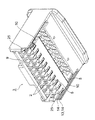
以下、図面を参照しながら説明する。図1は本発明のコネクタの一実施の形態を示す図(端子二次係止部材の仮係止状態の図)であり、(a)は連結部の位置での縦断面図、(b)はコネクタ中心線の位置での縦断面図である。また、図2は端子二次係止部材の仮係止状態と本係止状態とを示す図であり、(a)はコネクタの側面図、(b)は仮係止状態におけるA−A線断面図と要部拡大図、(b)は本係止状態におけるA−A線断面図と要部拡大図である。さらに、図3は下側から見たコネクタハウジングの斜視図、図4は端子二次係止部材の本係止状態の図であり、連結部の位置での縦断面図である。 Hereinafter, description will be given with reference to the drawings. FIG. 1 is a view showing a connector according to an embodiment of the present invention (a view of a temporary locking state of a terminal secondary locking member), (a) is a longitudinal sectional view at the position of a connecting portion, and (b). These are the longitudinal cross-sectional views in the position of a connector centerline. 2A and 2B are diagrams showing a temporary locking state and a final locking state of the terminal secondary locking member, where FIG. 2A is a side view of the connector, and FIG. 2B is an AA line in the temporary locking state. Sectional drawing and principal part enlarged view, (b) is the sectional view on the AA line and principal part enlarged view in this latching state. FIG. 3 is a perspective view of the connector housing as viewed from below, and FIG. 4 is a view of the terminal secondary locking member in the final locking state, and is a longitudinal sectional view at the position of the connecting portion.
図1において、引用符号1は本発明のコネクタを示している。コネクタ1は、図示しない複数の電線を束ねてなるワイヤハーネスの端末に設けられて、例えばワイヤハーネス同士を接続する際に用いられるようになっている。コネクタ1は、複数の端子収容室2を有するコネクタハウジング3と、このコネクタハウジング3の端子収容室2に収容される端子(図示省略。ここでは公知の雌端子であるものとする)と、コネクタハウジング3に対して仮係止状態又は本係止状態となり且つ端子を二次的に(二重に)係止する端子二次係止部材4とを備えて構成されている。先ず、上記各構成部材について説明する。
In FIG. 1,
図1ないし図3において、上記コネクタハウジング3は、絶縁性を有する合成樹脂製の部材であって、矢印Pを前後方向、矢印Qを左右方向(紙面垂直方向)、矢印Rを上下方向と定義すると、複数の端子収容室2は、左右方向に並ぶとともに上下二段となるように配置されている。また、複数の端子収容室2は、前後方向に貫通するように形成されている。端子収容室2は、図示しない端子の形状に合わせて形成されている。
1 to 3, the
尚、端子は、箱状の電気接触部と、この電気接触部に連続する電線接続部とを有している。端子は、上記電線の端末に接続されている。箱状の電気接触部には、相手コネクタにおける相手端子のタブ状電気接触部が差し込まれるようになっている。端子は、端子収容室2の後部開口から(コネクタハウジング3の後面から)内部に差し込まれると、端子収容室2に形成されるランス5によって係止され、後方への抜けが規制されるようになっている。
In addition, the terminal has a box-shaped electrical contact portion and an electric wire connection portion continuous to the electrical contact portion. The terminal is connected to the end of the electric wire. The tab-shaped electrical contact portion of the mating terminal in the mating connector is inserted into the box-shaped electrical contact portion. When the terminal is inserted into the inside from the rear opening of the terminal housing chamber 2 (from the rear surface of the connector housing 3), the terminal is locked by the
ランス5は、端子を係止するための部分(一次係止部分)であって、可撓性を有するように形成されている。ランス5は、片持ちの形状に形成されている。ランス5の先端部分には、端子を係止するための係止部が形成されている。端子収容室2は、ランス5の上方側が端子収容空間6、ランス5の下側がランス撓み空間兼治具挿入空間7となっている。ランス5は、ランス撓み空間兼治具挿入空間7側に撓むことによって端子の通過を許容することができるようになっている。ランス5は、上記係止部が端子収容空間6に突出するように形成されている。端子収容空間6とランス撓み空間兼治具挿入空間7は、コネクタハウジング3の前面において上下に並んで開口するように形成されている。
The
コネクタハウジング3には、部材収容凹部8(従来例のスペーサ収容凹部に相当)と、カバー収容凹部9と、一対の連結部収容溝10とが形成されている。部材収容凹部8は、端子二次係止部材4を上下方向に移動させて仮係止状態又は本係止状態とするための部分として形成されている。部材収容凹部8は、コネクタハウジング3の下面略中央から各端子収容室2に達するような凹部として形成されている。部材収容凹部8は、ランス5の後方に開口するように形成されている。このような部材収容凹部8の左右両側には、端子二次係止部材4に対する仮係止部分11及び本係止部分12が形成されている。尚、仮係止部分11及び本係止部分12は、特許請求の範囲に記載した後側係止構造に相当するものとする。
The
カバー収容凹部9は、コネクタハウジング3の下面前端部から各端子収容室2に達するような凹部として形成されている。また、カバー収容凹部9は、コネクタハウジング3の前面を凹ませるような部分にも形成されている。
The
一対の連結部収容溝10は、部材収容凹部8及びカバー収容凹部9の左右両側に配置形成されている。また、一対の連結部収容溝10は、部材収容凹部8とカバー収容凹部9とを連通する(これらを繋ぐ)溝として形成されている。一対の連結部収容溝10は、コネクタハウジング3の下面で左右両側位置に開口するように形成されている。このような一対の連結部収容溝10には、特許請求の範囲に記載した前側係止構造を構成する仮係止部分13及び本係止部分14が形成されている。仮係止部分13及び本係止部分14は、端子二次係止部材4に対する係止部分であって、前後方向に伸びる浅底の溝形状にそれぞれ形成されている。仮係止部分13は下側のみの溝、本係止部分14は上下両方の溝となっている。
The pair of connecting
コネクタハウジング3において、引用符号15は相手コネクタとの嵌合部分を示している。
In the
上記端子二次係止部材4は、所謂スペーサの機能(端子を二次的に(二重に)係止する)と、所謂フロントホルダの機能(端子の前方への抜けを規制する)とを有する部材であって、具体的には二次係止部16と、フロントカバー部17と、これらを連結する一対の連結部18とを有している。端子二次係止部材4は、二次係止部16、フロントカバー部17、及び一対の連結部18が一体化して一つの部品となるように形成されている。二次係止部16は所謂スペーサとして、また、フロントカバー部17は所謂フロントホルダとして形成されている。端子二次係止部材4は、絶縁性を有する合成樹脂製の部品であるものとする。
The terminal secondary locking member 4 has a so-called spacer function (secondarily (doublely) locks the terminal) and a so-called front holder function (to restrict the terminal from being pulled forward). Specifically, it has a
二次係止部16は、複数の端子係止部19と、一対の仮係止突起部20と、一対の本係止突起部21とを有している。各部分に関し、端子係止部19は、端子収容室2の数及び配置に合わせて複数形成されている。端子係止部19は、端子収容室2に収容されランス5により係止された状態の端子を引っ掛けて(箱状の電気接触部の端部を引っ掛けて)、この端子を二重に係止することができるような形状に形成されている。
The
仮係止突起部20は、コネクタハウジング3の部材収容凹部8に形成される仮係止部分11に引っ掛かる部分として形成されている。仮係止突起部20は、二次係止部16における左右両側部位置に配置形成されている。仮係止突起部20は、可撓性を有し且つ先端に爪状の部分を有する短いアーム形状に形成されている(形状は一例であるものとする)。
The
本係止突起部21は、コネクタハウジング3の部材収容凹部8に形成される本係止部分12に引っ掛かる部分として形成されている。本係止突起部21は、二次係止部16における左右両側位置に配置形成されている。本係止突起部21は、仮係止突起部20よりも後方に配置形成されている。本係止突起部21は、上下方向に長いスリット部分と、このスリット部分を形成することにより撓み可能となる撓み部分と、撓み部分から後方に小さく突出する略三角形状の突起部分とを有している(形状は一例であるものとする)。
The
仮係止突起部20及び本係止突起部21は、特許請求の範囲に記載した後側係止構造に相当するものとする。
The
フロントカバー部17は、コネクタハウジング3の前面位置で上下方向に移動する部分として形成されている。また、フロントカバー部17は、端子の前方への抜けを規制する部分としても形成されている。このようなフロントカバー部17には、端子収容室2の数及び位置に合わせて貫通する複数の間口22と、前面位置ガイド部23とが形成されている。間口22は、相手コネクタの相手端子の大きさに合わせて、また、ランス5の係止状態を解除するための係止解除治具(図示省略)の大きさに合わせて形成されている(必要以上に大きく開口するものでないものとする)。
The
複数の間口22は、左右方向に並ぶとともに上下二段となるように配置されている。また、複数の間口22は、前後方向に貫通するようにも形成されている。尚、間口22の周囲には、フロントカバー部17の肉厚部分24があるものとする。
The plurality of
前面位置ガイド部23は、端子二次係止部材4がコネクタハウジング3に対して本係止状態になる際に、コネクタハウジング3のストッパ部分25に当接する部分として形成されている。
The front
一対の連結部18は、上記の如く、二次係止部16とフロントカバー部17とを連結する部分として形成されている。一対の連結部18は、コネクタハウジング3の左右両側壁の内側に位置する一対の連結部収容溝10に差し込まれて上下方向に移動するようになっている。一対の連結部18の各外面には、リブ26が二本平行に形成されている。リブ26は、二次係止部16及びフロントカバー部17の連結方向に伸びて形成されている。もう少し詳しく説明すると、リブ26は、連結部18が二次係止部16に連続する位置及びフロントカバー部17に連続する位置に跨るように形成されている。一対の連結部18は、リブ26を形成することによって、この部分が厚肉となるように形成されている。
The pair of connecting
一対の連結部18は、リブ26を形成することによって、この外面が凹凸するような形状になっている。二本のリブ26は、上側のみが仮係止用のリブ26、上下両方が本係止用のリブ26となっている。二本のリブ26は、特許請求の範囲に記載した前側係止構造を構成するようになっている。
The pair of connecting
上記前側係止構造や後側係止構造は、端子二次係止部材4やコネクタハウジング3における前後方向の長い範囲に形成されている。
The front side locking structure and the rear side locking structure are formed in a long range in the front-rear direction of the terminal secondary locking member 4 and the
次に、上記構成及び構造に基づきながら、コネクタ1の組み立てについて説明する。
Next, the assembly of the
端子二次係止部材4をコネクタハウジング3の下側に配置し、この後に上方へと移動させてコネクタハウジング3に対する装着を行うと、端子二次係止部材4の二次係止部16がコネクタハウジング3の部材収容凹部8に差し込まれるとともに、フロントカバー部17もコネクタハウジング3のカバー収容凹部9に差し込まれて上方へと移動する。さらに、端子二次係止部材4の一対の連結部18も一対の連結部収容溝10に差し込まれて上方へと移動する。
When the terminal secondary locking member 4 is arranged on the lower side of the
そして、端子二次係止部材4における二次係止部16の一対の仮係止突起部20をコネクタハウジング3の仮係止部分11に対して引っ掛けるとともに、一対の連結部18の仮係止用のリブ26をコネクタハウジング3の仮係止部分13に引っ掛けると、図1(a)及び図2(b)に示す如くの仮係止状態が形成される。
Then, the pair of
尚、端子二次係止部材4がコネクタハウジング3に対し仮係止状態にある時には、相手コネクタとの嵌合を行うことは不能である。
When the terminal secondary locking member 4 is temporarily locked with respect to the
仮係止状態にある端子二次係止部材4を上方に更に押し込み、端子二次係止部材4をコネクタハウジング3に対して本係止状態にすると、すなわち二次係止部16の一対の本係止突起部21をコネクタハウジング3の本係止部分12に対して引っ掛けるとともに、一対の連結部18の本係止用のリブ26をコネクタハウジング3の本係止部分14に引っ掛けると、図2(c)及び図4に示す如くの本係止状態が形成され、これによりコネクタ1の組み立てが完了する。
When the terminal secondary locking member 4 in the temporary locking state is further pushed upward to bring the terminal secondary locking member 4 into the main locking state with respect to the
以上、図1ないし図4を参照しながら説明してきたように、本発明のコネクタ1は、リブ26を形成し従来よりも格段に厚肉となる一対の連結部18を有する端子二次係止部材4を構成に含んでいる。従って、本発明によれば、一対の連結部18の強度や剛性を従来よりも高めることができる。また、一対の連結部18にリブ26を形成することにより、端子二次係止部材4自体の変形を従来よりも起こり難くすることができる(例えば、端子二次係止部材4を装着する際に、二次係止部16から離れた位置のフロントカバー部17が傾くようなことはない)。
As described above with reference to FIGS. 1 to 4, the
この他、本発明によれば、リブ26を形成することにより、一対の連結部18の断面積を従来よりも増加させることができる。また、断面積を増加させるに当たり、リブ26を二次係止部16とフロントカバー部17との連結方向に伸びるように形成していることから、樹脂成形時における溶融樹脂の流動方向を一致させ、結果、流動性の向上を図ることができる。
In addition, according to the present invention, by forming the
本発明によれば、一対の連結部18のリブ26を係止構造として利用し、そして、前側係止構造及び後側係止構造を有することから、端子二次係止部材4をコネクタハウジング3に対してバランス良く係止することができる。
According to the present invention, since the
本発明のコネクタ1は、端子二次係止部材4の強度を従来よりも高め、また、成形時における溶融樹脂の流動性を従来よりも向上させ、さらには、従来よりも形状の安定化を図ることができるという効果を奏する。
The
本発明は本発明の主旨を変えない範囲で種々変更実施可能なことは勿論である。 It goes without saying that the present invention can be variously modified without departing from the spirit of the present invention.
ところで、コネクタ1の上記組み立てにおいて、端子二次係止部材4がコネクタハウジング3に対し仮係止状態になると、フロントカバー部17の複数の間口22は、対応する端子収容室2のランス撓み空間兼治具挿入空間7にのみ連通する。間口22がランス撓み空間兼治具挿入空間7に連通することから、図示しない係止解除治具を挿入してランス5による端子の係止状態を解除することが可能になる。
By the way, in the above assembly of the
一方、本係止状態への移行に伴ってフロントカバー部17の複数の間口22は、上方に移動し位置が変わることから、間口22は対応する端子収容室2の端子収容空間6のみに連通する。これに対してランス撓み空間兼治具挿入空間7は、間口22の周囲の肉厚部分24によって覆われる(図示省略)ことから、コネクタ1は、相手コネクタとの嵌合が行われても相手端子がランス撓み空間兼治具挿入空間7に差し込まれるような誤挿入が起こることはない。
On the other hand, since the plurality of
1 コネクタ
2 端子収容室
3 コネクタハウジング
4 端子二次係止部材
5 ランス
6 端子収容空間
7 ランス撓み空間兼治具挿入空間
8 部材収容凹部
9 カバー収容凹部
10 連結部収容溝
11 仮係止部分(後側係止構造)
12 本係止部分(後側係止構造)
13 仮係止部分(前側係止構造)
14 本係止部分(前側係止構造)
15 嵌合部分
16 二次係止部
17 フロントカバー部
18 連結部
19 端子係止部
20 仮係止突起部(後側係止構造)
21 本係止突起部(後側係止構造)
22 間口
23 前面位置ガイド部
24 肉厚部分
25 ストッパ部分
26 リブ(前側係止構造)
DESCRIPTION OF
12 locking parts (rear locking structure)
13 Temporary locking part (front locking structure)
14 locking parts (front locking structure)
DESCRIPTION OF
21 locking projections (rear locking structure)
22
Claims (2)
該端子二次係止部材は、前記端子収容室のランスにより係止された前記端子を更に二次的に係止する二次係止部と、前記コネクタハウジングの前面位置で上下方向に移動し且つ前記端子の前方への抜けを規制するフロントカバー部と、前記二次係止部及び前記フロントカバー部を連結する連結部とを有し、
前記コネクタハウジングは、該コネクタハウジングの下面から前記端子収容室に達するような凹部として形成される、前側のカバー収容凹部及び後側の部材収容凹部を有してなるコネクタにおいて、
前記コネクタハウジングは、該コネクタハウジングの下面で左右両側の内側位置に開口し、且つ、前記左右両側の厚みよりも開口幅が広く、且つ、前記カバー収容凹部及び前記部材収容凹部を連通するように前後方向に伸びて形成される一対の連結部収容溝を有し、
前記連結部は、左右一対であるとともに、前記二次係止部及び前記フロントカバー部の連結方向である前記前後方向に伸び、且つ、前記コネクタハウジングの前記左右両側よりも厚肉で、且つ、前記一対の連結部収容溝にそれぞれ差し込まれて前記上下方向に移動する形状を有し、
このような一対の前記連結部の外面は、前記二次係止部及び前記フロントカバー部に連続する位置に跨るように前記前後方向に伸び、且つ、前記連結部を更に厚肉にする形状のリブを有する
ことを特徴とするコネクタ。 A connector housing made of a synthetic resin having a terminal and a plurality of terminal housing chambers penetrating in the front-rear direction for receiving the terminal from the rear, and a temporarily locked state or a fully locked state with respect to the connector housing by moving in the vertical direction And a synthetic resin terminal secondary locking member,
The terminal secondary locking member moves in a vertical direction at a secondary locking portion for secondary locking the terminal locked by the lance of the terminal accommodating chamber and a front position of the connector housing. And a front cover portion for restricting the terminal from coming out forward, and a connecting portion for connecting the secondary locking portion and the front cover portion ,
The connector housing is a connector having a front cover housing recess and a rear member housing recess formed as a recess reaching the terminal housing chamber from the lower surface of the connector housing .
The connector housing opens to the inner positions on the left and right sides on the lower surface of the connector housing, has an opening width wider than the thickness on both the left and right sides, and communicates the cover housing recess and the member housing recess. Having a pair of connecting portion receiving grooves formed extending in the front-rear direction;
The connecting portion is a pair of left and right , extends in the front-rear direction which is a connecting direction of the secondary locking portion and the front cover portion , and is thicker than the left and right sides of the connector housing, and Having a shape that is inserted into the pair of connecting portion receiving grooves and moves in the up and down direction,
The outer surfaces of the pair of connecting portions extend in the front-rear direction so as to straddle the positions that are continuous with the secondary locking portion and the front cover portion, and have a shape that further thickens the connecting portions. A connector having a rib .
前記コネクタハウジングに対し前記端子二次係止部材を前記仮係止状態又は前記本係止状態にする部分として後側係止構造及び前側係止構造を有し、
前記後側係止構造としては、前記部材収容凹部において左右一対に形成される仮係止部分及び本係止部分と、前記二次係止部において左右一対に形成される仮係止突起部及び本係止突起部とを有し、
前記前側係止構造としては、一対の前記連結部収容溝にそれぞれ形成されて前記前後方向に伸びる浅底の溝形状の仮係止部分及び本係止部分と、一対の前記連結部の外面にそれぞれ二本形成される前記リブとを有する
ことを特徴とするコネクタ。 The connector according to claim 1,
A rear side locking structure and a front side locking structure as a part that makes the terminal secondary locking member the temporary locking state or the main locking state with respect to the connector housing,
As the rear side locking structure, a temporary locking portion and a main locking portion formed in a pair of left and right in the member receiving recess, a temporary locking protrusion formed in a pair of left and right in the secondary locking portion, and With a locking projection,
As the front side locking structure, a shallow groove-shaped temporary locking portion and a main locking portion that are respectively formed in the pair of connecting portion receiving grooves and extend in the front-rear direction, and an outer surface of the pair of connecting portions. A connector having two ribs each formed .
Priority Applications (1)
| Application Number | Priority Date | Filing Date | Title |
|---|---|---|---|
| JP2008283938A JP5394696B2 (en) | 2008-11-05 | 2008-11-05 | connector |
Applications Claiming Priority (1)
| Application Number | Priority Date | Filing Date | Title |
|---|---|---|---|
| JP2008283938A JP5394696B2 (en) | 2008-11-05 | 2008-11-05 | connector |
Publications (2)
| Publication Number | Publication Date |
|---|---|
| JP2010113872A JP2010113872A (en) | 2010-05-20 |
| JP5394696B2 true JP5394696B2 (en) | 2014-01-22 |
Family
ID=42302294
Family Applications (1)
| Application Number | Title | Priority Date | Filing Date |
|---|---|---|---|
| JP2008283938A Expired - Fee Related JP5394696B2 (en) | 2008-11-05 | 2008-11-05 | connector |
Country Status (1)
| Country | Link |
|---|---|
| JP (1) | JP5394696B2 (en) |
Families Citing this family (1)
| Publication number | Priority date | Publication date | Assignee | Title |
|---|---|---|---|---|
| JP6278863B2 (en) * | 2014-08-05 | 2018-02-14 | 日本航空電子工業株式会社 | connector |
Family Cites Families (4)
| Publication number | Priority date | Publication date | Assignee | Title |
|---|---|---|---|---|
| JP3710957B2 (en) * | 1999-04-28 | 2005-10-26 | 矢崎総業株式会社 | Connector and method of assembling the connector |
| JP2004152621A (en) * | 2002-10-30 | 2004-05-27 | Sumitomo Wiring Syst Ltd | Connector |
| JP2008047476A (en) * | 2006-08-21 | 2008-02-28 | Fci Connectors Singapore Pte Ltd | Connector |
| JP2008171626A (en) * | 2007-01-10 | 2008-07-24 | Yazaki Corp | Connector |
-
2008
- 2008-11-05 JP JP2008283938A patent/JP5394696B2/en not_active Expired - Fee Related
Also Published As
| Publication number | Publication date |
|---|---|
| JP2010113872A (en) | 2010-05-20 |
Similar Documents
| Publication | Publication Date | Title |
|---|---|---|
| JP4926836B2 (en) | connector | |
| JP4760683B2 (en) | connector | |
| JP4457927B2 (en) | connector | |
| JP5656121B2 (en) | connector | |
| JP4088189B2 (en) | connector | |
| US9017108B2 (en) | Electrical connector | |
| CN102780113B (en) | Electrical connector and harness | |
| JP6393301B2 (en) | connector | |
| CN110534951B (en) | Connector with a locking member | |
| JP5098875B2 (en) | connector | |
| CN110323613B (en) | Connector and terminal component | |
| JP5012072B2 (en) | Board connector | |
| JP5682061B2 (en) | connector | |
| JP4483529B2 (en) | connector | |
| WO2016059947A1 (en) | Connector | |
| JP6280080B2 (en) | Connector with aligning plate | |
| JP5394696B2 (en) | connector | |
| JP5247904B2 (en) | Electrical connector assembly | |
| JP5183315B2 (en) | connector | |
| JP5272934B2 (en) | connector | |
| JP4636072B2 (en) | connector | |
| WO2024057856A1 (en) | Connector | |
| WO2018207651A1 (en) | Connector | |
| US11728589B2 (en) | Connector | |
| JP5565184B2 (en) | connector |
Legal Events
| Date | Code | Title | Description |
|---|---|---|---|
| A621 | Written request for application examination |
Free format text: JAPANESE INTERMEDIATE CODE: A621 Effective date: 20110928 |
|
| A131 | Notification of reasons for refusal |
Free format text: JAPANESE INTERMEDIATE CODE: A131 Effective date: 20121218 |
|
| A02 | Decision of refusal |
Free format text: JAPANESE INTERMEDIATE CODE: A02 Effective date: 20130716 |
|
| A521 | Written amendment |
Free format text: JAPANESE INTERMEDIATE CODE: A523 Effective date: 20130827 |
|
| A911 | Transfer of reconsideration by examiner before appeal (zenchi) |
Free format text: JAPANESE INTERMEDIATE CODE: A911 Effective date: 20130917 |
|
| TRDD | Decision of grant or rejection written | ||
| A01 | Written decision to grant a patent or to grant a registration (utility model) |
Free format text: JAPANESE INTERMEDIATE CODE: A01 Effective date: 20131015 |
|
| A61 | First payment of annual fees (during grant procedure) |
Free format text: JAPANESE INTERMEDIATE CODE: A61 Effective date: 20131017 |
|
| R150 | Certificate of patent or registration of utility model |
Free format text: JAPANESE INTERMEDIATE CODE: R150 |
|
| LAPS | Cancellation because of no payment of annual fees |