JP5393264B2 - Objective optical system position adjustment device and observation device - Google Patents
Objective optical system position adjustment device and observation device Download PDFInfo
- Publication number
- JP5393264B2 JP5393264B2 JP2009133449A JP2009133449A JP5393264B2 JP 5393264 B2 JP5393264 B2 JP 5393264B2 JP 2009133449 A JP2009133449 A JP 2009133449A JP 2009133449 A JP2009133449 A JP 2009133449A JP 5393264 B2 JP5393264 B2 JP 5393264B2
- Authority
- JP
- Japan
- Prior art keywords
- optical system
- objective optical
- unit
- diameter
- objective
- Prior art date
- Legal status (The legal status is an assumption and is not a legal conclusion. Google has not performed a legal analysis and makes no representation as to the accuracy of the status listed.)
- Expired - Fee Related
Links
Images


Classifications
-
- G—PHYSICS
- G02—OPTICS
- G02B—OPTICAL ELEMENTS, SYSTEMS OR APPARATUS
- G02B21/00—Microscopes
- G02B21/0004—Microscopes specially adapted for specific applications
- G02B21/0012—Surgical microscopes
-
- A—HUMAN NECESSITIES
- A61—MEDICAL OR VETERINARY SCIENCE; HYGIENE
- A61B—DIAGNOSIS; SURGERY; IDENTIFICATION
- A61B1/00—Instruments for performing medical examinations of the interior of cavities or tubes of the body by visual or photographical inspection, e.g. endoscopes; Illuminating arrangements therefor
- A61B1/00147—Holding or positioning arrangements
- A61B1/00154—Holding or positioning arrangements using guiding arrangements for insertion
-
- A—HUMAN NECESSITIES
- A61—MEDICAL OR VETERINARY SCIENCE; HYGIENE
- A61B—DIAGNOSIS; SURGERY; IDENTIFICATION
- A61B1/00—Instruments for performing medical examinations of the interior of cavities or tubes of the body by visual or photographical inspection, e.g. endoscopes; Illuminating arrangements therefor
- A61B1/32—Devices for opening or enlarging the visual field, e.g. of a tube of the body
-
- G—PHYSICS
- G01—MEASURING; TESTING
- G01N—INVESTIGATING OR ANALYSING MATERIALS BY DETERMINING THEIR CHEMICAL OR PHYSICAL PROPERTIES
- G01N21/00—Investigating or analysing materials by the use of optical means, i.e. using sub-millimetre waves, infrared, visible or ultraviolet light
- G01N21/01—Arrangements or apparatus for facilitating the optical investigation
-
- G—PHYSICS
- G02—OPTICS
- G02B—OPTICAL ELEMENTS, SYSTEMS OR APPARATUS
- G02B21/00—Microscopes
- G02B21/02—Objectives
-
- G—PHYSICS
- G02—OPTICS
- G02B—OPTICAL ELEMENTS, SYSTEMS OR APPARATUS
- G02B21/00—Microscopes
- G02B21/24—Base structure
- G02B21/248—Base structure objective (or ocular) turrets
-
- A—HUMAN NECESSITIES
- A61—MEDICAL OR VETERINARY SCIENCE; HYGIENE
- A61B—DIAGNOSIS; SURGERY; IDENTIFICATION
- A61B1/00—Instruments for performing medical examinations of the interior of cavities or tubes of the body by visual or photographical inspection, e.g. endoscopes; Illuminating arrangements therefor
- A61B1/313—Instruments for performing medical examinations of the interior of cavities or tubes of the body by visual or photographical inspection, e.g. endoscopes; Illuminating arrangements therefor for introducing through surgical openings, e.g. laparoscopes
-
- A—HUMAN NECESSITIES
- A61—MEDICAL OR VETERINARY SCIENCE; HYGIENE
- A61B—DIAGNOSIS; SURGERY; IDENTIFICATION
- A61B2503/00—Evaluating a particular growth phase or type of persons or animals
- A61B2503/40—Animals
Landscapes
- Physics & Mathematics (AREA)
- Health & Medical Sciences (AREA)
- Life Sciences & Earth Sciences (AREA)
- Surgery (AREA)
- Optics & Photonics (AREA)
- General Health & Medical Sciences (AREA)
- Chemical & Material Sciences (AREA)
- Analytical Chemistry (AREA)
- General Physics & Mathematics (AREA)
- Pathology (AREA)
- Biophysics (AREA)
- Heart & Thoracic Surgery (AREA)
- Veterinary Medicine (AREA)
- Nuclear Medicine, Radiotherapy & Molecular Imaging (AREA)
- Radiology & Medical Imaging (AREA)
- Engineering & Computer Science (AREA)
- Biomedical Technology (AREA)
- Public Health (AREA)
- Medical Informatics (AREA)
- Molecular Biology (AREA)
- Animal Behavior & Ethology (AREA)
- Immunology (AREA)
- Biochemistry (AREA)
- Microscoopes, Condenser (AREA)
- Endoscopes (AREA)
Description
本発明は、対物光学系位置調整装置および観察装置に関するものである。 The present invention relates to an objective optical system position adjusting device and an observation device.
近年、小動物などの生体試料の内部、例えば、脳深部や臓器などの様子を生きたままの状態(in vivo)で観察することが重要となってきている。そのために、生体への侵襲を小さくして比較的長期間にわたって生体内の経時観察を可能とする細径先端部を有する対物光学系および顕微鏡システムが知られている(例えば、特許文献1および特許文献2参照。)。
In recent years, it has become important to observe the inside of a biological sample such as a small animal, for example, the state of a deep brain or an organ in a living state (in vivo). Therefore, there are known an objective optical system and a microscope system having a small-diameter tip portion that can reduce the invasion to a living body and enable temporal observation in the living body for a relatively long period of time (for example,
また、生体内を経時的に観察する場合、観察期間中に小動物等に平常時と同様の活動をさせようとすると、観察部位に位置決めされていた対物光学系を一旦取り外して、観察時に再度同一の観察部位に対物光学系を位置決めする必要がある。このときに、生体に固定された支持部材の挿入孔内に対物光学系を挿入することにより、対物光学系を高い再現性で位置決めする固定装置が知られている(例えば、特許文献3参照)。 In addition, when observing the inside of a living body over time, if an attempt is made to cause a small animal or the like to perform the same activity as normal during the observation period, the objective optical system positioned at the observation site is temporarily removed and the same is again performed during observation. It is necessary to position the objective optical system at the observation site. At this time, there is known a fixing device that positions the objective optical system with high reproducibility by inserting the objective optical system into the insertion hole of the support member fixed to the living body (see, for example, Patent Document 3). .
しかしながら、細径先端部を有する対物光学系と固定装置とを併用して生体に低侵襲でかつ比較的長期間にわたって生体内を観察しようとした場合、支持部材による生体への侵襲を低減するために、挿入孔の内径寸法を細径先端部の外径寸法よりわずかに大きい程度にとどめることが望ましい。 However, in order to reduce the invasion of the living body by the support member when the objective optical system having a small-diameter tip and the fixing device are used together to minimize the invasion of the living body and observe the inside of the living body for a relatively long period of time. In addition, it is desirable to keep the inner diameter of the insertion hole slightly larger than the outer diameter of the small-diameter tip.
そのために、挿入孔を細径化すると、挿入孔から取り外した細径先端部を再度挿入孔に挿入する際に、細径先端部と挿入孔との間の空隙がわずかしかないため、対物光学系の位置合わせが難しくなるという問題がある。また、細径先端部の位置が挿入孔からずれて細径先端部が支持部材に衝突すると、大きな力がかかってこれらが破損したり、衝突時の衝撃により生体に影響を及ぼしたりしてしまう恐れがあるという問題がある。 Therefore, if the insertion hole is made thinner, there is only a small gap between the small diameter tip and the insertion hole when the small diameter tip removed from the insertion hole is inserted again into the insertion hole. There is a problem that alignment of the system becomes difficult. In addition, if the position of the small-diameter tip is displaced from the insertion hole and the small-diameter tip collides with the support member, a large force is applied and these components are damaged or the living body is affected by the impact at the time of the collision. There is a problem of fear.
本発明は、上述した事情に鑑みてなされたものであって、支持部材の挿入孔が細径であっても、対物光学系や支持部材の破損および生体への影響を防ぎながら対物光学系の細径先端部を容易に挿入孔内へ挿入することができる対物光学系位置調整装置および観察装置を提供することを目的としている。 The present invention has been made in view of the above-described circumstances, and even if the insertion hole of the support member has a small diameter, the objective optical system is protected from damage to the objective optical system and the support member and the influence on the living body. An object of the present invention is to provide an objective optical system position adjusting device and an observation device that can easily insert a small-diameter tip portion into an insertion hole.
上記目的を達成するために、本発明は以下の手段を提供する。
本発明は、細径先端部を有する対物光学系と、該対物光学系により集光された光を観察するための観察光学系との間に配置される位置調整ユニットと、生体に一端が固定され、前記細径先端部を内部に挿脱可能に支持する略筒状の支持ユニットとを備え、前記位置調整ユニットが、前記対物光学系を保持する保持部と、該保持部を前記対物光学系の光軸方向と交差する方向に移動自在に支持する移動機構とを備え、前記細径先端部を前記支持ユニットに挿脱する際に、前記保持部が前記移動機構によって前記光軸方向と交差する方向に滑らかに移動することで、前記対物光学系の位置を前記支持ユニットに対して調整し、前記支持ユニットが、その他端部に、他端に向かって漸次径寸法が大きくなるテーパ状の内面を有する対物光学系位置調整装置を提供する。
In order to achieve the above object, the present invention provides the following means.
The present invention relates to a position adjusting unit disposed between an objective optical system having a small-diameter tip and an observation optical system for observing light condensed by the objective optical system, and one end fixed to a living body. A substantially cylindrical support unit that removably supports the tip of the small diameter inside, the position adjusting unit holding the objective optical system, and the holding unit as the objective optical A moving mechanism that movably supports in a direction crossing the optical axis direction of the system, and when the small-diameter tip portion is inserted into and removed from the support unit, the holding portion is moved to the optical axis direction by the moving mechanism. by smoothly moved in a direction intersecting the position of the objective optical system to adjust relative to the support unit, the support unit, the other end portion, tapered progressively diameter increases toward the other end Objective optical system with inner surface To provide a device.
本発明によれば、生体に固定された支持ユニット内に対物光学系の細径先端部を挿入することにより、対物光学系の位置を生体に対して同一の位置に位置決めして所定の観察部位を経時的に観察することができる。
この場合に、細径先端部を支持ユニット内に挿入する際に、細径先端部の位置が支持ユニットに対してずれていると、細径先端部の先端がテーパ状の内面に接触し、該内面の形状にならって保持部および対物光学系が移動機構により移動させられることにより、対物光学系の位置が調整されながら細径先端部が支持ユニット内へ案内される。
According to the present invention, by inserting the small-diameter tip of the objective optical system into the support unit fixed to the living body, the position of the objective optical system is positioned at the same position with respect to the living body, and a predetermined observation site Can be observed over time.
In this case, when the small diameter tip is inserted into the support unit, if the position of the small diameter tip is displaced with respect to the support unit, the tip of the small diameter tip contacts the tapered inner surface, The holding portion and the objective optical system are moved by the moving mechanism in accordance with the shape of the inner surface, so that the small-diameter tip is guided into the support unit while the position of the objective optical system is adjusted.
これにより、細径先端部の高い位置合わせの精度が不要となり、挿入孔の内径寸法を細径先端部の外径寸法と略同一の寸法まで小さくしても、細径先端部を容易に支持ユニット内に挿入することができる。また、細径先端部の先端が支持ユニットに接触しても、対物光学系が接触から逃げる方向に移動することにより接触時の衝撃が緩衝され、対物光学系および支持ユニットの破損および生体への影響を防ぐことができる。 This eliminates the need for high alignment accuracy for the small diameter tip, and supports the small diameter tip easily even if the inner diameter of the insertion hole is reduced to approximately the same as the outer diameter of the small diameter tip. Can be inserted into the unit. Even if the tip of the small-diameter tip comes into contact with the support unit, the impact at the time of contact is buffered by moving the objective optical system in the direction of escaping from the contact, causing damage to the objective optical system and the support unit and to the living body. The effect can be prevented.
上記発明においては、前記移動機構が、前記対物光学系の光軸方向に略垂直な平面内において互いに垂直な方向に前記保持部を案内する2つの直線ガイドを備えることとしてもよい。
このようにすることで、対物光学系を、光軸方向に略垂直な平面内において滑らかに移動させることができる。
In the above invention, the moving mechanism may include two linear guides for guiding the holding unit in directions perpendicular to each other in a plane substantially perpendicular to the optical axis direction of the objective optical system.
By doing so, the objective optical system can be smoothly moved in a plane substantially perpendicular to the optical axis direction.
また、上記発明においては、前記直線ガイドが、ベアリング機構を備えることとしてもよい。
このようにすることで、対物光学系を潤滑に移動させることができる。
Moreover, in the said invention, the said linear guide is good also as providing a bearing mechanism.
By doing in this way, an objective optical system can be moved to lubrication.
また、上記発明においては、前記位置調整ユニットが、前記保持部の移動を規制する規制手段を備えることとしてもよい。
このようにすることで、細径先端部を挿入孔内に挿入した状態で保持部の移動を規制して対物光学系の移動を防止し、視野をより安定させながら観察することができる。
Moreover, in the said invention, the said position adjustment unit is good also as providing the control means which controls the movement of the said holding | maintenance part.
By doing so, it is possible to observe the image while stabilizing the field of view by preventing the movement of the objective optical system by restricting the movement of the holding part in a state where the small-diameter tip is inserted into the insertion hole.
また、上記発明においては、前記位置調整ユニットが、前記保持部により保持された前記対物光学系の光軸の位置を、前記観察光学系の光軸の位置に一致するように調整する光軸調整手段を備えることとしてもよい。
このようにすることで、対物光学系の光軸の位置を観察光学系の光軸と容易に一致させることができる。
また、本発明は、上記いずれかに記載の対物光学系位置調整装置を備える観察装置を提供する。
In the above invention, the position adjustment unit adjusts the position of the optical axis of the objective optical system held by the holding unit so as to coincide with the position of the optical axis of the observation optical system. Means may be provided.
In this way, the position of the optical axis of the objective optical system can be easily matched with the optical axis of the observation optical system.
Moreover, this invention provides an observation apparatus provided with the objective optical system position adjustment apparatus in any one of the said.
本発明によれば、支持部材の挿入孔が細径であっても、対物光学系や支持部材の破損および生体への影響を防ぎながら対物光学系を容易に挿入孔内へ挿入することができるという効果を奏する。 According to the present invention, even if the insertion hole of the support member has a small diameter, the objective optical system can be easily inserted into the insertion hole while preventing damage to the objective optical system and the support member and the influence on the living body. There is an effect.
本発明の一実施形態に係る対物光学系位置調整装置1および観察装置100について、図1〜図9を参照して以下に説明する。なお、本実施形態においては、生きたマウス(生体)Aの脳内を観察する場合を例に挙げて説明する。
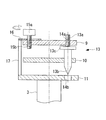
本実施形態に係る観察装置100は、図1に示されるように、正立型の光学顕微鏡をベースとしており、顕微鏡(観察光学系)2と、該顕微鏡2に装着され対物光学系3が取り付けられた位置調整ユニット4およびマウスAに固定された支持ユニット5を備える本実施形態に係る対物光学系位置調整装置1とを備えている。
An objective optical system
As shown in FIG. 1, the
顕微鏡2は、一般的な光学顕微鏡またはレーザ走査型顕微鏡が用いられる。顕微鏡2は、位置調整ユニット4が取り付けられるユニット取付部6を有している。ユニット取付部6は、一般に対物光学系のマウントに用いられる構造になっており、例えば、RMSネジが設けられている。ユニット取付部6を光軸方向に沿って上下に移動させることにより、ユニット取付部6に取り付けられた位置調整ユニット4および対物光学系3の高さ方向の位置が調節されるようになっている。マウスAは、水平面内において移動可能なステージ7上に載置され、固定具8によって頭部がステージ7に対して固定されている。
As the
対物光学系3は、細径先端部3aを有している。また、対物光学系3は、無限遠設計であり、対物光学系3の先端から集光された光は略平行光束になって後方の光学系へ伝達されるようになっている。
The objective
位置調整ユニット4は、図2に示されるように、顕微鏡2側から順に、顕微鏡取付部9、中間部10および対物取付部(保持部)11を備えている。また、顕微鏡取付部9と中間部10との間にはX軸ガイド12a(移動機構、直線ガイド)が配置され、中間部10と対物取付部11との間にはY軸ガイド12b(移動機構、直線ガイド)が配置されている。X軸ガイド12aおよびY軸ガイド12bは、顕微鏡2の光軸に垂直な平面内において互いに垂直な方向に移動可能であり、潤滑性に優れたもの、例えば、ベアリング(ベアリング機構)を備えたものが用いられる。これにより、対物取付部11が、顕微鏡取付部9に対して水平面内において移動自在に支持されている。
As shown in FIG. 2, the
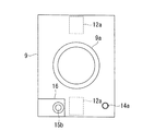
顕微鏡取付部9は、図3に示されるように、顕微鏡2のユニット取付部6に着脱可能な顕微鏡取付ネジ9aを有し、該顕微鏡取付ネジ9aをユニット取付部6に取り付けることにより、位置調整ユニット4が顕微鏡2に搭載されるようになっている。また、顕微鏡取付部9の略中央には、対物取付部11近傍まで延びる遮光筒9bが設けられている。これにより、顕微鏡2と対物光学系3との間の光路が外部から遮光され、顕微鏡2からの照射光2および対物光学系3により集光された観察光に外来光が混入することが防止されるようになっている。
As shown in FIG. 3, the
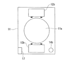
中間部10は、図4に示されるように、略中央部に遮光筒9bが貫通する中間部穴10aが設けられている。中間部穴10aは、中間部10が顕微鏡取付部9に対して水平方向に移動したときに、その移動が遮光筒9bにより制限されないように、遮光筒9bの外径寸法より大きい内径寸法を有している。
対物取付部11は、図5に示されるように、対物光学系3の後部が着脱可能な対物取付ネジ穴11aが略中央部に貫通している。
As shown in FIG. 4, the
As shown in FIG. 5, the
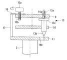
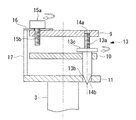
顕微鏡取付部9および対物取付部11には、遮光筒9bと対物取付ネジ穴11aとが略同心軸上に配置されたときに一致する位置に、中心出しネジ(光軸調整手段)13が挿入される顕微鏡側中心出しネジ穴(光軸調整手段)14aおよび対物側中心出し穴(光軸調整手段)14bが厚さ方向に貫通している。中心出しネジ13は、後方部分のネジ部13aが、顕微鏡側中心出しネジ穴14aに嵌合し、先端部分の漸次先細に形成された円錐部13bが、対物側中心出し穴14bに挿入されている。
A centering screw (optical axis adjusting means) 13 is inserted into the
これにより、中心出しネジ13の途中位置に設けられた回転ネジ13cを締める方向に回転させると、対物光学系3の光軸と顕微鏡2の光軸とが一致する位置に対物取付部11の位置が調整されるようになっている。なお、中間部10の四隅には切欠10bが設けられ、これにより、中間部10および中心出しネジ13は、互いに位置が制限されることなく移動可能になっている。
As a result, when the
また、顕微鏡取付部9には、固定ネジ(規制手段)15aが嵌合する固定ネジ穴(規制手段)15bが設けられ、固定ネジ15aを締め付けて、固定ネジ15aと顕微鏡取付部9との間に配置されたシム16を顕微鏡取付部9に固定することにより、シム16と対物取付部11とを連結する連結部材17を介して対物取付部11が顕微鏡取付部9に対して固定されるようなっている。
Further, the
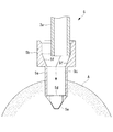
支持ユニット5は、図6に示されるように、生体内に挿入される細径部5aと、該細径部5aより大きい径寸法を有する大径部5bとを有する略筒状である。細径部5a内には、対物光学系3の細径先端部3aの外径寸法よりわずかに大きい内径寸法を有する挿入孔5cが長手方向に沿って延び、挿入孔5cの底面には、対物光学系3と試料表面との間の光路となる中央部に、カバーガラス等の透明材料からなる窓5dが設けられている。
As shown in FIG. 6, the
細径部5aの先端は、挿入孔5cの底面から試料表面との間に適切な距離の空間を空けて、ガラス等の透明部材5eによって閉塞されている。これにより、細径先端部3aを、その先端面が挿入孔5cの底面に突き当る位置まで挿入孔5c内に挿入すると、対物光学系3の焦点が試料表面に適切に合うようになっている。
大径部5bは、挿入孔5cの内面から連続して円錐状に径寸法が大きくなる内面5fを有している。
The distal end of the
The large-
このように構成された対物光学系位置調整装置1および観察装置100の使用方法および作用について、図7〜図10を参照して以下に説明する。なお、図7〜図9においては、説明箇所の構成を分かりやすくするため、一部の構成を省略することとする。
本実施形態に係る観察装置100を用いてマウスAの脳内をin vivoで観察するには、マウスAの頭蓋骨に穿孔した貫通孔に細径部5aを挿入した状態で支持ユニット5を接着固定し、マウスAの頭部をステージ7に固定する。
The usage method and operation of the objective optical system
In order to observe the inside of the brain of the mouse A in vivo using the
まず、固定ネジ15aを緩めて対物光学系3を略水平面内において移動自在にした状態で(図7参照。)、中心出しネジ13を締めて対物光学系3の光軸を顕微鏡2の光軸と一致する位置に調整し、固定ネジ15aを締めて対物光学系3を顕微鏡2に対して固定する(図8参照。)。この状態で中心出しネジ13を緩めると、対物光学系3は、その光軸が顕微鏡2の光軸と一致する位置に保持される。
First, in a state where the fixing
次に、挿入孔5cが対物光学系3の略鉛直下方に配置されるようにステージ7を移動させて対物光学系3と観察部位との位置合わせをしたら、固定ネジ15aを緩めて対物光学系3を移動自在にした状態で(図9参照。)、対物光学系3を下方へゆっくり移動させて細径先端部3aを挿入孔5c内へ挿入していく。
Next, when the
このときに、対物光学系3の位置が挿入孔5cからずれていると、細径先端部3aの先端がテーパ状の内面5fに接触し(図10参照。)、該内面5fに沿って細径先端部3aが滑らかに移動しながら挿入孔5cの位置まで案内されて、そのまま挿入孔5c内へ挿入される。細径先端部3aを挿入孔5cの底面に突き当る位置まで挿入したら、固定ネジ15aを締めて対物光学系3の位置を固定し、顕微鏡2によりマウスAの脳内をin vivoで観察することができる。
At this time, if the position of the objective
このように、本実施形態によれば、支持ユニット5に、挿入孔5cに向かって漸次径寸法が小さくなる内面5fを設け、対物光学系3を、挿入方向に交差する方向に滑らかに移動自在にした状態で挿入孔5c内に挿入する。これにより、細径先端部3aの位置が挿入孔5cからずれていても挿入の過程でその位置が調整される。したがって、挿入孔5cの内径寸法を細径先端部3aの外径寸法と略同一まで縮小化しても、対物光学系3の高い位置精度の制御を必要とすることなく、細径先端部3aを挿入孔5c内に容易に挿入することができるという利点がある。
As described above, according to the present embodiment, the
また、このようにして挿入孔5cの径寸法を可能な限り小さくすることにより、支持ユニット5によるマウスAへの侵襲をさらに低減しながら、マウスAの体内を比較的長期間にわたって観察することができるという利点がある。また、細径先端部3aの先端がテーパ状の内面5fに接触しても、その接触による衝撃を緩衝する方向に細径先端部3aが滑らかに移動することにより、細径先端部3aおよび支持ユニット5の破損を防止し、また、接触時の衝撃による生体や観察部位への影響を防ぐことができるという利点がある。
In addition, by reducing the diameter of the
また、対物光学系3が光軸方向に交差する方向に移動自在な構成であっても、必要に応じて対物光学系3の位置が顕微鏡2に対して簡便な方法で固定される。これにより、光軸の調整後に対物光学系3が移動して光軸がずれてしまう等の不都合を防止し、また、観察時には視野のブレなどを防いでより安定した画像を得ることができるという利点がある。
Even if the objective
上記実施形態においては、ユニット取付部6が、対物光学系3の光軸方向に移動可能であることとしたが、これに代えて、ステージ7が、対物光学系3の光軸方向に移動可能であることしてもよい。
このようにしても、上記実施形態と同様の効果を得ることができる。
また、上記実施形態においては、正立型の顕微鏡2を用いることとしたが、これに代えて、倒立型の顕微鏡を用いることとしてもよい。
In the above embodiment, the unit mounting portion 6 is movable in the optical axis direction of the objective
Even if it does in this way, the effect similar to the said embodiment can be acquired.
In the above embodiment, the
また、上記実施形態においては、顕微鏡取付部9が、顕微鏡取付ネジ9aによって対物光学系3のマウントと同様の構造で顕微鏡2に取り付けられることとしたが、これに代えて、レボルバのマウントと同様の構造で顕微鏡2に取り付けられることとしてもよい。
また、上記実施形態においては、対物取付部11は、対物光学系3に代えて、レボルバが取り付けられることとしてもよい。このようにすることで、対物取付部11に取り付けられたレボルバに、仕様の異なる複数の対物光学系3を取り付け、倍率等を容易に変更しながら観察することができる。
In the above embodiment, the
In the above-described embodiment, the
また、上記実施形態においては、対物光学系3とステージ7との角度が調整可能になっていてもよい。この場合、ステージ7を傾斜させてもよく、対物光学系3および位置調整ユニット4を含む光学系を傾斜させてもよい。
マウスAの頭部に固定された支持ユニット5は、挿入孔5cの長手方向が対物光学系3の光軸に対して傾いて配置される場合も有り得る。したがって、挿入孔5cの長手方向が対物光学系3の光軸方向に沿うようにステージ7と対物光学系3との角度を調整することにより、細径先端部3aを適切な方向から容易に挿入孔5c内に挿入することができる。
In the above embodiment, the angle between the objective
The
このときに、例えば、標本をステージ7に固定した状態で、対物光学系3と同程度の長さ寸法を有する棒状部材、または、対物光学系3の外筒と同様の形状の物を挿入孔5c内に挿入し、これらの中心軸が顕微鏡2の光軸に一致するようにステージ7と対物光学系3との角度を調整する。これにより、ステージ7と対物光学系3との角度を容易に調整することができる。または、挿入孔5cを塞ぐ位置に光を反射する反射部材、例えば、鏡を取り付け、顕微鏡2で観察される像の輝度が最も高くなる角度を選択することによっても、ステージ7と対物光学系3との角度を容易に調整することができる。
At this time, for example, in a state where the specimen is fixed to the
1 対物光学系位置調整装置
2 顕微鏡(観察光学系)
3 対物光学系
3a 細径先端部
4 位置調整ユニット
5 支持ユニット
5a 細径部
5b 大径部
5c 挿入孔
5d 窓
5e 透明部材
5f 内面
6 ユニット取付部
7 ステージ
8 固定具
9 顕微鏡取付部
9a 顕微鏡取付ネジ
9b 遮光筒
10 中間部
10a 中間部穴
10b 切欠
11 対物取付部(保持部)
11a 対物取付ネジ穴
12a X軸ガイド(移動機構、直線ガイド)
12b Y軸ガイド(移動機構、直線ガイド)
13 中心出しネジ(光軸調整手段)
13a ネジ部
13b 円錐部
13c 回転ネジ
14a 顕微鏡側中心出しネジ穴(光軸調整手段)
14b 対物側中心出し穴(光軸調整手段)
15a 固定ネジ(規制手段)
15b 固定ネジ穴(規制手段)
16 シム(規制手段)
17 連結部材(規制手段)
100 観察装置
A マウス(生体)
1 Objective optical system
DESCRIPTION OF
11a Objective mounting
12b Y-axis guide (moving mechanism, linear guide)
13 Centering screw (Optical axis adjusting means)
14b Objective-side centering hole (optical axis adjustment means)
15a Fixing screw (regulation means)
15b Fixing screw hole (regulation means)
16 shim (regulatory means)
17 Connecting member (regulation means)
100 Observation device A Mouse (living body)
Claims (7)
生体に一端が固定され、前記細径先端部を内部に挿脱可能に支持する略筒状の支持ユニットとを備え、
前記位置調整ユニットが、前記対物光学系を保持する保持部と、該保持部を前記対物光学系の光軸方向と交差する方向に移動自在に支持する移動機構とを備え、前記細径先端部を前記支持ユニットに挿脱する際に、前記保持部が前記移動機構によって前記光軸方向と交差する方向に滑らかに移動することで、前記対物光学系の位置を前記支持ユニットに対して調整し、
前記支持ユニットが、その他端部に、他端に向かって漸次径寸法が大きくなるテーパ状の内面を有する対物光学系位置調整装置。 A position adjusting unit disposed between an objective optical system having a small-diameter tip and an observation optical system for observing light condensed by the objective optical system;
A substantially cylindrical support unit that has one end fixed to a living body and supports the small-diameter tip portion in an insertable and removable manner;
Wherein the position adjustment unit, wherein comprises a holding portion for holding the objective optical system, and a moving mechanism for movably supporting the holding unit in a direction intersecting the optical axis direction of the objective optical system, the narrow-diameter end portion When the holder is inserted into and removed from the support unit, the holding unit smoothly moves in the direction intersecting the optical axis direction by the moving mechanism, thereby adjusting the position of the objective optical system with respect to the support unit. ,
Said support unit, the other end portion, the objective optical system position adjustment device having a tapered inner surface which progressively diameter increases toward the other end.
Priority Applications (2)
| Application Number | Priority Date | Filing Date | Title |
|---|---|---|---|
| JP2009133449A JP5393264B2 (en) | 2009-06-02 | 2009-06-02 | Objective optical system position adjustment device and observation device |
| US12/790,112 US8405903B2 (en) | 2009-06-02 | 2010-05-28 | Objective-optical-system positioning apparatus and examination apparatus |
Applications Claiming Priority (1)
| Application Number | Priority Date | Filing Date | Title |
|---|---|---|---|
| JP2009133449A JP5393264B2 (en) | 2009-06-02 | 2009-06-02 | Objective optical system position adjustment device and observation device |
Publications (3)
| Publication Number | Publication Date |
|---|---|
| JP2010279437A JP2010279437A (en) | 2010-12-16 |
| JP2010279437A5 JP2010279437A5 (en) | 2012-07-12 |
| JP5393264B2 true JP5393264B2 (en) | 2014-01-22 |
Family
ID=43300571
Family Applications (1)
| Application Number | Title | Priority Date | Filing Date |
|---|---|---|---|
| JP2009133449A Expired - Fee Related JP5393264B2 (en) | 2009-06-02 | 2009-06-02 | Objective optical system position adjustment device and observation device |
Country Status (2)
| Country | Link |
|---|---|
| US (1) | US8405903B2 (en) |
| JP (1) | JP5393264B2 (en) |
Families Citing this family (3)
| Publication number | Priority date | Publication date | Assignee | Title |
|---|---|---|---|---|
| JP2018529125A (en) | 2015-09-02 | 2018-10-04 | インスコピックス, インコーポレイテッド | System and method for color imaging |
| JP2018533768A (en) | 2015-11-05 | 2018-11-15 | インスコピックス, インコーポレイテッド | System and method for optogenetics imaging |
| US20210169334A1 (en) * | 2019-12-05 | 2021-06-10 | Regents Of The University Of Minnesota | Systems and methods for multimodal neural sensing |
Family Cites Families (9)
| Publication number | Priority date | Publication date | Assignee | Title |
|---|---|---|---|---|
| JP2501098B2 (en) * | 1984-06-25 | 1996-05-29 | オリンパス光学工業株式会社 | microscope |
| US5295477A (en) * | 1992-05-08 | 1994-03-22 | Parviz Janfaza | Endoscopic operating microscope |
| CH689968A5 (en) * | 1993-07-30 | 2000-02-29 | Zeiss Carl Fa | Monitoring and / or documentation device with upstream endoscope and method for its operation. |
| US5588949A (en) * | 1993-10-08 | 1996-12-31 | Heartport, Inc. | Stereoscopic percutaneous visualization system |
| EP1524542B1 (en) * | 2003-10-17 | 2008-07-02 | Olympus Corporation | Objective lens insertion tool & objective optical system attachment device |
| JP4579563B2 (en) * | 2004-03-15 | 2010-11-10 | オリンパス株式会社 | Objective optical system fixing device |
| JP2005241671A (en) | 2004-02-24 | 2005-09-08 | Olympus Corp | Microscope system and object unit |
| US7304789B2 (en) * | 2004-02-24 | 2007-12-04 | Olympus Corporation | Microscope system and objective unit |
| JP4504153B2 (en) | 2004-10-20 | 2010-07-14 | オリンパス株式会社 | Immersion objective optical system |
-
2009
- 2009-06-02 JP JP2009133449A patent/JP5393264B2/en not_active Expired - Fee Related
-
2010
- 2010-05-28 US US12/790,112 patent/US8405903B2/en not_active Expired - Fee Related
Also Published As
| Publication number | Publication date |
|---|---|
| US8405903B2 (en) | 2013-03-26 |
| JP2010279437A (en) | 2010-12-16 |
| US20100309547A1 (en) | 2010-12-09 |
Similar Documents
| Publication | Publication Date | Title |
|---|---|---|
| US7903327B2 (en) | Fluorescence microscope apparatus | |
| JP4504479B2 (en) | Immersion objective lens for microscope | |
| JP5393264B2 (en) | Objective optical system position adjustment device and observation device | |
| EP1712945A3 (en) | Microscope examination apparatus | |
| EP1757969A1 (en) | Microscope moving unit and microscope apparatus | |
| JP2008043771A (en) | Attachment module for fundus examination and operation microscope with it | |
| WO2001071406A1 (en) | Microscope unit | |
| US8964287B2 (en) | Device for focusing a microscope objective on a sample | |
| EP2912507B1 (en) | Scanning lens system and method of reducing reaction forces therein | |
| US6288838B1 (en) | Video-type stereoscopic microscope including movable field stop frame and holder | |
| US10768405B2 (en) | Microscope having an objective-exchanging device | |
| CN215839007U (en) | Fixing frame with medical magnifier | |
| JP2011112880A (en) | Microscope | |
| DE102006048056A1 (en) | Method and arrangement for focusing objectives, objects and condensers in microscopes | |
| JP4932384B2 (en) | Living body observation device | |
| US10539591B2 (en) | Measuring device for a scanning probe microscope, scanning probe microscope and method for operating the scanning probe microscope | |
| CN112603561A (en) | Miniature multi-photon microscopic imaging device and using method | |
| EP1708005A1 (en) | Objective lens unit for an in-vivo examination apparatus, comprising a lens barrel with indentations in an end surface | |
| JP4043991B2 (en) | Microscope observation apparatus and probe type microscope | |
| KR101309494B1 (en) | Tilting device installed at zoom body tube | |
| JP4928638B2 (en) | microscope | |
| JP4819989B2 (en) | microscope | |
| JP2007057765A (en) | Microscope apparatus | |
| JPH1184257A (en) | Microscope | |
| JP2005300655A (en) | Laser-scanning observation apparatus |
Legal Events
| Date | Code | Title | Description |
|---|---|---|---|
| A521 | Written amendment |
Free format text: JAPANESE INTERMEDIATE CODE: A523 Effective date: 20120528 |
|
| A621 | Written request for application examination |
Free format text: JAPANESE INTERMEDIATE CODE: A621 Effective date: 20120528 |
|
| A977 | Report on retrieval |
Free format text: JAPANESE INTERMEDIATE CODE: A971007 Effective date: 20130711 |
|
| A131 | Notification of reasons for refusal |
Free format text: JAPANESE INTERMEDIATE CODE: A131 Effective date: 20130723 |
|
| A521 | Written amendment |
Free format text: JAPANESE INTERMEDIATE CODE: A523 Effective date: 20130920 |
|
| TRDD | Decision of grant or rejection written | ||
| A01 | Written decision to grant a patent or to grant a registration (utility model) |
Free format text: JAPANESE INTERMEDIATE CODE: A01 Effective date: 20131008 |
|
| A61 | First payment of annual fees (during grant procedure) |
Free format text: JAPANESE INTERMEDIATE CODE: A61 Effective date: 20131015 |
|
| S531 | Written request for registration of change of domicile |
Free format text: JAPANESE INTERMEDIATE CODE: R313531 |
|
| R350 | Written notification of registration of transfer |
Free format text: JAPANESE INTERMEDIATE CODE: R350 |
|
| LAPS | Cancellation because of no payment of annual fees |