JP5390436B2 - Electric construction machine - Google Patents
Electric construction machine Download PDFInfo
- Publication number
- JP5390436B2 JP5390436B2 JP2010050384A JP2010050384A JP5390436B2 JP 5390436 B2 JP5390436 B2 JP 5390436B2 JP 2010050384 A JP2010050384 A JP 2010050384A JP 2010050384 A JP2010050384 A JP 2010050384A JP 5390436 B2 JP5390436 B2 JP 5390436B2
- Authority
- JP
- Japan
- Prior art keywords
- rotational speed
- electric motor
- travel
- mode switch
- speed
- Prior art date
- Legal status (The legal status is an assumption and is not a legal conclusion. Google has not performed a legal analysis and makes no representation as to the accuracy of the status listed.)
- Active
Links
Images


Landscapes
- Operation Control Of Excavators (AREA)
Description
本発明は、バッテリ駆動の電動モータを動力源とする電動式建設機械に関する。 The present invention relates to an electric construction machine using a battery-driven electric motor as a power source.
例えば油圧ショベル等の電動式建設機械として、車両に搭載されたメインバッテリを用いて電動モータを駆動すると共に、この電動モータを駆動源として油圧ポンプを作動させ、該油圧ポンプにて生成した油圧を用いて作業装置の油圧シリンダや走行用の油圧モータを駆動するものが知られている(例えば、特許文献1参照)。 For example, as an electric construction machine such as a hydraulic excavator, an electric motor is driven using a main battery mounted on a vehicle, a hydraulic pump is operated using the electric motor as a drive source, and the hydraulic pressure generated by the hydraulic pump is generated. A device that uses a hydraulic cylinder of a working device or a traveling hydraulic motor is known (for example, see Patent Document 1).
また、エンジン駆動式の建設機械として、緊急時にスイッチ操作を行うことによって、エンジンの回転数および油圧ポンプの容量を最大にすると共に、油圧モータの容量を最小にして、走行速度を上昇させるものが知られている(例えば、特許文献2参照)。 Also, as an engine-driven construction machine, one that increases the running speed by minimizing the capacity of the hydraulic motor while maximizing the engine speed and the capacity of the hydraulic pump by performing a switch operation in an emergency. It is known (see, for example, Patent Document 2).
さらに、エンジン駆動式の建設機械として、作業装置のみが操作されているときには、エンジンの出力を低く抑え、車両の走行時には出力制限を解除して高速走行させる構成も知られている(例えば、特許文献3参照)。 Further, as an engine-driven construction machine, a configuration is also known in which when only a work device is operated, the output of the engine is kept low, and the output restriction is released when the vehicle is running to run at high speed (for example, a patent Reference 3).
ところで、電動式建設機械では、例えば作業装置を用いた掘削作業時には、メインバッテリの電力消費を抑えるために、電動モータの回転数を低下させた方がよい。一方、車両を高速走行させるときには、電動モータの回転数を上昇させて、油圧ポンプからの圧油の供給量を増加させる必要がある。 By the way, in an electric construction machine, for example, during excavation work using a working device, it is better to reduce the rotation speed of the electric motor in order to suppress the power consumption of the main battery. On the other hand, when the vehicle is traveling at a high speed, it is necessary to increase the amount of pressure oil supplied from the hydraulic pump by increasing the rotational speed of the electric motor.
これに対し、特許文献2,3には、車両の走行速度が上昇可能となった構成が開示されている。しかし、これらの建設機械では、車両の走行速度を上昇させるために、緊急スイッチやロックレバー等の特別な切換え手段を操作してエンジンの出力を調整する必要があり、車両の走行速度を上昇させるための操作が煩雑になって、作業性が低下するという問題がある。
In contrast,
本発明は上述した従来技術の問題に鑑みなされたもので、本発明の目的は、簡易な操作によって車両の走行速度を上昇させることができる電動式建設機械を提供することにある。 The present invention has been made in view of the above-described problems of the prior art, and an object of the present invention is to provide an electric construction machine that can increase the traveling speed of a vehicle by a simple operation.
上述した課題を解決するために、請求項1の発明による電動式建設機械は、運転席が設けられた自走可能な車体と、該車体に設けられたメインバッテリと、該メインバッテリから供給される直流電圧を昇圧する昇圧回路と、該昇圧回路から供給される直流電力を交流電力に変換するインバータと、該インバータから供給される交流電力によって駆動する電動モータと、該電動モータによって駆動する油圧ポンプと、該油圧ポンプによる油圧を用いて駆動し、容量切換弁による容量の切換えに応じて前記車体を高速または低速で走行させる可変容量型の走行用油圧モータと、前記車体に設けられ、オペレータの走行操作に応じて該走行用油圧モータを制御するための走行操作装置と、前記走行用油圧モータの容量切換弁を切換え操作して前記車体の走行速度として高速および低速のいずれかを選択する走行モードスイッチと、前記電動モータの回転数を設定する回転数設定器と、前記メインバッテリの電力消費を抑制するための省エネモードスイッチと、前記走行モードスイッチおよび該省エネモードスイッチに応じて前記インバータを制御し、前記電動モータの回転数を制御する回転数制御装置とを備え、前記回転数制御装置は、前記省エネモードスイッチを省エネモードに切換えた場合に、前記走行操作装置の走行操作に拘らず前記回転数設定器によって設定された設定回転数で前記電動モータを駆動させる省エネモード駆動装置と、前記省エネモードスイッチを非省エネモードに切換えた場合に、前記走行モードスイッチによって高速側が選択された状態で、前記走行操作装置が中立位置にあるときに前記回転数設定器によって設定された設定回転数で前記電動モータを駆動させ、前記走行操作装置を走行操作したときに前記電動モータの回転数を上昇させる非省エネモード駆動装置とを備える構成としている。
In order to solve the above-described problem, an electric construction machine according to the invention of
請求項2の発明では、前記走行操作装置が中立位置にあるときに前記電動モータを最大回転数で駆動可能にするパワーモードスイッチを備え、前記回転数設定器は、該パワーモードスイッチをパワーモードに切換えた場合には、前記設定回転数を前記電動モータの最大回転数以下の範囲で設定可能とし、該パワーモードスイッチを非パワーモードに切換えた場合には、前記設定回転数を前記電動モータの最大回転数に比べて低速な所定回転数以下の範囲で設定可能としている。 According to a second aspect of the present invention, a power mode switch is provided that enables the electric motor to be driven at a maximum number of revolutions when the travel operation device is in a neutral position, and the revolution number setting device is configured to switch the power mode switch to a power mode. When the power mode switch is switched to the non-power mode, the set rotational speed can be set within a range equal to or less than the maximum rotational speed of the electric motor. It can be set in a range of a predetermined rotation speed that is lower than the maximum rotation speed.
請求項3の発明では、前記非省エネモード駆動装置は、前記パワーモードスイッチを非パワーモードに切換えた場合に、前記走行操作装置の操作量が予め決められた第1のしきい値を超えたときに前記電動モータの回転数を上昇させる通常モード処理装置と、前記パワーモードスイッチをパワーモードに切換えた場合に、前記走行操作装置の操作量が前記第1のしきい値よりも小さい第2のしきい値を超えたときに前記電動モータの回転数を上昇させるパワーモード処理装置とを備える構成としている。 In the invention of claim 3, when the power mode switch is switched to the non-power mode, the operation amount of the travel operation device exceeds a predetermined first threshold value. A normal mode processing device that sometimes increases the rotational speed of the electric motor, and a second operation amount of the travel operation device smaller than the first threshold value when the power mode switch is switched to the power mode. And a power mode processing device that increases the rotational speed of the electric motor when the threshold value is exceeded.
請求項4の発明では、前記走行モードスイッチ、省エネモードスイッチ、パワーモードスイッチおよび回転数設定器は、前記運転席の近傍に配置されたコンソールに取り付ける構成としている。 According to a fourth aspect of the invention, the travel mode switch, the energy saving mode switch, the power mode switch, and the rotation speed setting device are attached to a console disposed in the vicinity of the driver seat.
請求項5の発明では、前記メインバッテリの異常を検出するバッテリコントローラを設け、前記非省エネモード駆動装置は、該バッテリコントローラによって前記メインバッテリの異常を検出したときには、前記走行操作装置の走行操作に拘らず前記回転数設定器によって設定された設定回転数で前記電動モータを駆動させるバッテリ異常処理装置を備える構成としている。 According to a fifth aspect of the present invention, a battery controller that detects an abnormality of the main battery is provided, and the non-energy-saving mode drive device performs a traveling operation of the traveling operation device when the abnormality of the main battery is detected by the battery controller. Regardless, the battery abnormality processing device is configured to drive the electric motor at the set rotational speed set by the rotational speed setter.
上述の如く、請求項1に記載の発明によれば、省エネモード駆動装置は、省エネモードスイッチを省エネモードに切換えた場合には、走行用レバー、走行用ペダル等からなる走行操作装置の走行操作に関係なく回転数設定器によって設定された設定回転数で電動モータを駆動させる。このため、車両を停止させた状態で掘削作業等を行うときには、設定回転数を低速に設定することによって、メインバッテリの電力消費を確実に抑えることができ、当該建設機械の稼動時間を長くすることができる。 As described above, according to the first aspect of the present invention, when the energy saving mode switch is switched to the energy saving mode, the energy saving mode drive device performs the traveling operation of the traveling operation device including the traveling lever, the traveling pedal, and the like. The electric motor is driven at the set rotational speed set by the rotational speed setter regardless of the above. For this reason, when excavation work or the like is performed with the vehicle stopped, the power consumption of the main battery can be reliably suppressed by setting the set rotational speed to a low speed, and the operating time of the construction machine is lengthened. be able to.
一方、非省エネモード駆動装置は、省エネモードスイッチを非省エネモードに切換えた場合には、走行モードスイッチによって高速側が選択された状態で、走行操作装置が中立位置にあるときに回転数設定器によって設定された設定回転数で電動モータを駆動させ、走行操作装置を走行操作したときに電動モータの回転数を上昇させる。これにより、車両を走行させるときに、オペレータが予め走行モードスイッチを高速側に設定しておけば、走行操作装置の走行操作を行うだけで電動モータの回転数を自動的に上昇させることができる。また、走行操作装置を中立位置に戻したときには電動モータの回転数を設定回転数まで低下させることができる。このため、例えば車両を高速走行させるときでも、電動モータの回転数を上昇させるための特別な操作が必要なく、走行操作装置を走行操作するだけでよいため、操作を簡略化して作業性を高めることができる。 On the other hand, the non-energy-saving mode drive device, when the energy-saving mode switch is switched to the non-energy-saving mode, uses the rotation speed setting device when the traveling operation device is in the neutral position with the high-speed side selected by the traveling mode switch. The electric motor is driven at the set rotational speed that is set, and the rotational speed of the electric motor is increased when the travel operation device is traveled. As a result, when the vehicle is driven, if the operator sets the travel mode switch to the high speed side in advance, the rotational speed of the electric motor can be automatically increased only by performing the travel operation of the travel operation device. . Further, when the traveling operation device is returned to the neutral position, the rotational speed of the electric motor can be reduced to the set rotational speed. For this reason, for example, even when the vehicle is traveling at a high speed, there is no need for a special operation for increasing the rotation speed of the electric motor, and it is only necessary to travel the traveling operation device, thus simplifying the operation and improving workability. be able to.
請求項2の発明によれば、回転数設定器は、パワーモードスイッチをパワーモードに切換えた場合には、設定回転数を電動モータの最大回転数以下の範囲で設定可能とした。このため、例えば重負荷での掘削作業を行う場合には、オペレータがパワーモードスイッチをパワーモードに切換えれば、走行操作装置が中立位置にあるときでも、最大回転数以下の範囲でオペレータによって設定された高速な設定回転数で電動モータを駆動させることができる。
According to the invention of
また、回転数設定器は、パワーモードスイッチを非パワーモードに切換えた場合には、設定回転数を電動モータの最大回転数に比べて低速な所定回転数以下の範囲で設定可能とした。例えば軽負荷での通常の掘削作業を行う場合には、電動モータの回転数は最大回転数よりも低い値で足りる。このため、軽負荷時には、設定回転数は最大回転数に比べて低速な所定回転数以下の値に設定されるから、電動モータの回転数を低下させてメインバッテリの電力消費を抑制することができる。 In addition, when the power mode switch is switched to the non-power mode, the rotational speed setter can set the rotational speed within a range below a predetermined rotational speed that is lower than the maximum rotational speed of the electric motor. For example, when a normal excavation operation with a light load is performed, a value lower than the maximum number of rotations of the electric motor is sufficient. For this reason, when the load is light, the set rotational speed is set to a value that is lower than the predetermined rotational speed, which is lower than the maximum rotational speed. Therefore, it is possible to reduce the rotational speed of the electric motor to suppress the power consumption of the main battery. it can.
請求項3の発明によれば、非省エネモード駆動装置の通常モード処理装置は、非省エネモードに切換わった状態でパワーモードスイッチを非パワーモードに切換えた通常モードでは、走行操作装置の操作量が予め決められた第1のしきい値を超えたときに電動モータの回転数を上昇させる構成とした。このため、通常モードでは、走行操作装置の操作量が第1のしきい値よりも小さいときには、電動モータの回転数は設定回転数に維持する。このとき、電動モータによって駆動する油圧ポンプは、車両の低速走行に応じた圧油を走行モータに供給することができる。また、走行操作装置の操作量が第1のしきい値よりも大きいときには、電動モータの回転数を上昇させる。これにより、電動モータによって駆動する油圧ポンプは、車両の高速走行に応じた圧油を走行モータに供給することができる。 According to the third aspect of the present invention, the normal mode processing device of the non-energy saving mode driving device operates in the normal mode in which the power mode switch is switched to the non-power mode in the state of switching to the non-energy saving mode. Is configured to increase the rotation speed of the electric motor when the value exceeds a predetermined first threshold value. For this reason, in the normal mode, when the operation amount of the travel operation device is smaller than the first threshold value, the rotation speed of the electric motor is maintained at the set rotation speed. At this time, the hydraulic pump driven by the electric motor can supply the traveling motor with pressure oil corresponding to the low-speed traveling of the vehicle. Further, when the operation amount of the travel operation device is larger than the first threshold value, the rotational speed of the electric motor is increased. Thereby, the hydraulic pump driven by the electric motor can supply pressure oil according to the high-speed traveling of the vehicle to the traveling motor.
一方、非省エネモード駆動装置のパワーモード処理装置は、非省エネモードに切換わった状態でパワーモードスイッチをパワーモードに切換えたときには、第2のしきい値を超えて走行操作装置を走行操作したときに電動モータの回転数を上昇させる構成とした。このため、パワーモードでは、走行操作装置の操作量が第2のしきい値よりも小さいときには、電動モータの回転数は設定回転数に維持する。また、走行操作装置の操作量が第2のしきい値よりも大きいときには、電動モータの回転数を上昇させる。これにより、電動モータによって駆動する油圧ポンプは、通常モードと同様に、車両の走行速度に応じた圧油を走行モータに供給することができる。 On the other hand, the power mode processing device of the non-energy-saving mode drive device operated the traveling operation device exceeding the second threshold when the power mode switch was switched to the power mode in the state of switching to the non-energy-saving mode. In some cases, the rotational speed of the electric motor is increased. For this reason, in the power mode, when the operation amount of the travel operation device is smaller than the second threshold value, the rotation speed of the electric motor is maintained at the set rotation speed. Further, when the operation amount of the travel operation device is larger than the second threshold value, the rotational speed of the electric motor is increased. Thereby, the hydraulic pump driven by the electric motor can supply pressure oil corresponding to the traveling speed of the vehicle to the traveling motor, as in the normal mode.
さらに、第2のしきい値は第1のしきい値よりも小さい値となっている。このため、パワーモードでは、通常モードに比べて小さい操作量で、電動モータの回転数を上昇させるから、速やかに車両を高速走行させることができる。 Further, the second threshold value is smaller than the first threshold value. For this reason, in the power mode, the rotational speed of the electric motor is increased with a smaller operation amount than in the normal mode, so that the vehicle can be driven at high speed quickly.
請求項4の発明によれば、走行モードスイッチ、省エネモードスイッチ、パワーモードスイッチおよび回転数設定器は、運転席の近傍に配置されたコンソールに取り付ける構成とした。このため、オペレータは、運転席に着座した状態で、走行モードスイッチ、省エネモードスイッチ、パワーモードスイッチおよび回転数設定器を操作することができ、省エネモード、通常モード、パワーモードを速やかに切換えることができる。
According to the invention of
請求項5の発明によれば、非省エネモード駆動装置のバッテリ異常処理装置は、バッテリコントローラによってメインバッテリの異常を検出したときには、走行操作装置の走行操作に拘らず回転数設定器によって設定された設定回転数で電動モータを駆動させる構成とした。このため、例えばメインバッテリの充電不足等のように、電動モータを高速回転で駆動させることが不適切な状況では、電動モータの回転数を設定回転数に維持することができる。 According to the invention of claim 5, when the battery controller detects the abnormality of the main battery by the battery controller, the battery abnormality processing device of the non-energy-saving mode drive device is set by the rotation speed setting device regardless of the traveling operation of the traveling operation device. The electric motor is driven at the set rotational speed. For this reason, in a situation where it is inappropriate to drive the electric motor at high speed rotation, for example, due to insufficient charging of the main battery, the rotation speed of the electric motor can be maintained at the set rotation speed.
以下、本発明の実施の形態による電動式建設機械として小型の油圧ショベルに適用した場合を例に挙げ、添付図面を参照しつつ詳細に説明する。 Hereinafter, a case where the present invention is applied to a small hydraulic excavator as an electric construction machine according to an embodiment of the present invention will be described as an example and described in detail with reference to the accompanying drawings.
図中、1は電動式建設機械としてのキャノピ仕様の油圧ショベルで、該油圧ショベル1は、図1および図2に示すように、自走可能なクローラ式の下部走行体2と、該下部走行体2上に旋回可能に搭載され、下部走行体2と共に油圧ショベル1の車体を構成する上部旋回体3と、後述の作業装置5とによって大略構成されている。この小型の油圧ショベル1は、旋回中心と上部旋回体3の後端との間の半径(後端旋回半径)が例えば1.5m以下(好ましくは1.3m以下)の値に設定されている。
In the figure,
下部走行体2は左,右の履帯2Aを備えると共に、該履帯2Aは遊動輪2Bと駆動輪2Cとの間に巻回されている。また、下部走行体2には、駆動輪2Cを回転駆動するために、後述する走行モータ36が設けられている。
The
4は上部旋回体3の支持構造体を構成する旋回フレームで、該旋回フレーム4は、下部走行体2上に旋回可能に設けられ、油圧モータからなる旋回モータ(図示せず)によって旋回動作する。また、旋回フレーム4の前部には、作業装置5(フロント装置)が俯仰動可能に取り付けられている。
この作業装置5は、ブーム6、アーム7、バケット8等によって構成され、ブーム6、アーム7、バケット8にはブームシリンダ9、アームシリンダ10、バケットシリンダ11等の油圧シリンダが取り付けられている。そして、これらのシリンダ9〜11は、走行モータ36や旋回モータ等と共に、後述の油圧ポンプ33から供給される油圧によって駆動するアクチュエータを構成している。
The working device 5 includes a boom 6, an
12は上部旋回体3に設けられた運転席で、該運転席12は、例えば旋回フレーム4の前部左側に配置され、オペレータが着座するものである。この運転席12の上側は、キャノピ13によって覆われている。また、運転席12の左,右両側には後述のコンソール15,16が設けられ、運転席12の前側には床板14上に位置して後述の走行レバー・ペダル装置29等が設けられている。
A driver's
15は乗降口に近い運転席12の左横脇に設けられた左側コンソールで、該左側コンソール15は、図3に示すように、コンソールボックス15Aを有し、該コンソールボックス15Aの前側には、傾転操作が可能な状態で左側の操作レバー15Bが設けられている。
15 is a left console provided on the left side of the driver's
16は運転席12の近傍として運転席12の右横脇に設けられた右側コンソールで、該右側コンソール16は、乗降口からみて運転席12よりも遠い位置に配置されている。この右側コンソール16は、左側コンソール15と同様に、コンソールボックス16Aおよび操作レバー16B等によって構成されている。そして、右側の操作レバー16Bは、左側の操作レバー15Bと共にオペレータが傾転操作することによって、例えば作業装置5等を作動させるものである。
17は右側コンソール16に設けられたスイッチボックスで、該スイッチボックス17の上面には、図4に示すように、ライトスイッチ18、走行モードスイッチ19、省エネモードスイッチ20、パワーモードスイッチ21が設けられると共に、回転数設定器としての回転数設定ダイヤル22が設けられている。
ここで、ライトスイッチ18は、前照灯等の照明ランプ(図示せず)を点灯または消灯させるためのスイッチである。また、走行モードスイッチ19は、車両の走行速度を高速側と低速側とに選択的に切換えるものであり、高速選択部19Aと低速選択部19Bとを備えている。そして、走行モードスイッチ19は、選択部19A,19Bに応じて、後述のように走行モータ36の容量可変部36Aを小容量と大容量とのいずれかに切換える機能を有する。
Here, the
具体的には、高速選択部19Aが選択されることによって、走行モードスイッチ19はオンになり、走行モータ36の容量可変部36Aを小容量に切換える。一方、低速選択部19Bが選択されることによって、走行モードスイッチ19はオフになり、走行モータ36の容量可変部36Aを大容量に切換える。
Specifically, when the high
省エネモードスイッチ20は、メインバッテリ40の電力消費を抑制するために設けられている。このため、省エネモードスイッチ20をオンにした省エネモードでは、電動モータ39は回転数設定ダイヤル22によって設定された設定回転数Nsで回転駆動する。一方、省エネモードスイッチ20をオフにした非省エネモードでは、パワーモードスイッチ21のオン/オフに応じて、後述の通常モードまたはパワーモードに切換わる。
The energy saving
パワーモードスイッチ21は、例えば重負荷での掘削作業等を行うときに、電動モータ39の回転数Nを高回転に保持するために設けられている。具体的に説明すると、パワーモードスイッチ21をオフにした非パワーモード(省エネモード、通常モード)では、回転数設定ダイヤル22による設定回転数Nsの設定範囲は、電動モータ39の最大回転数Nmaxよりも低い所定回転数N0(例えばN0=1800rpm)以下の範囲に限定される。
The
これに対し、パワーモードスイッチ21をオンにしたパワーモードでは、回転数設定ダイヤル22による設定回転数Nsの設定範囲が電動モータ39の最大回転数Nmax(例えばNmax=2400rpm)まで拡張される。これにより、パワーモードスイッチ21をオンにした場合には、後述の走行レバー・ペダル装置29が中立位置にあるときでも、電動モータ39は最大回転数Nmaxで回転駆動することができる。
On the other hand, in the power mode in which the
なお、パワーモードスイッチ21は、省エネモードスイッチ20と一緒にオンになることはなく、いずれか一方がオンのときには他方はオフになる。また、省エネモードスイッチ20およびパワーモードスイッチ21は、両方一緒にオフにすることもできる。これにより、省エネモードスイッチ20がオンになった省エネモード、パワーモードスイッチ21がオンになったパワーモード、およびこれら2個のスイッチ20,21が両方ともオフになった通常モードのうち、いずれか1つの動作モードが選択されるものである。
The
回転数設定ダイヤル22は、電動モータ39の回転数Nを設定するもので、その回転位置に応じて設定回転数Nsを決めるものである。この設定回転数Nsの設定範囲は、パワーモードスイッチ21のオン/オフに応じて異なる。具体的には、パワーモードスイッチ21がオンになるパワーモードでは、設定回転数Nsは、電動モータ39の最大回転数Nmax以下の範囲で設定可能になっている。本実施の形態では、設定回転数Nsは、例えば予め決められた最小回転数Nmin(例えばNmin=1300rpm)と最大回転数Nmaxとの間の範囲で設定可能となっている。
The rotation
一方、パワーモードスイッチ21がオフになる省エネモードおよび通常モードでは、設定回転数Nsは、電動モータ39の最大回転数Nmaxに比べて低速な所定回転数N0以下の範囲で設定可能になっている。具体的には、設定回転数Nsは、最大回転数Nmaxの75%となった所定回転数N0以下の範囲として、例えば最小回転数Nminと所定回転数N0の間の範囲で設定可能となる。これにより、パワーモードでは、省エネモードおよび通常モードに比べて設定回転数Nsを高めることができる。
On the other hand, in the energy saving mode and the normal mode in which the
なお、回転数設定器は、回転数設定ダイヤル22のように、回転位置に応じて設定回転数Nsが決まるダイヤル式に限らず、例えばスライド式、レバー式等の他の形式のものでもよい。
The rotation speed setting device is not limited to the dial type in which the set rotation speed Ns is determined according to the rotation position, such as the rotation
また、スイッチボックス17の上面には、油圧ショベル1の積算稼動時間を示す積算時間表示パネル23および後述するメインバッテリ40の電圧を示す電圧表示パネル24が設けられている。さらに、スイッチボックス17の上面には、油圧ショベル1が駆動可能な状態であることを示す駆動可能ランプ25、油圧ショベル1が駆動不能な状態であることを示す駆動不能ランプ26、メインバッテリ40の電圧が正常であることを示す電圧正常ランプ27、メインバッテリ40の電圧が低下していることを示す電圧異常ランプ28等が設けられている。
Further, on the upper surface of the
29は運転席12の前側に位置して床板14上に設けられた走行操作装置としての走行レバー・ペダル装置で、該走行レバー・ペダル装置29は、図3に示すように、左,右の走行用レバー30A,30Bと左,右の走行用ペダル31A,31Bとを備えている。そして、運転席12に着座したオペレータは、走行レバー・ペダル装置29の走行操作として、走行用レバー30A,30Bを手動で傾転操作したり、走行用ペダル31A,31Bを踏み込み操作したりすることにより、その操作量θに応じて車両の走行速度を増加、減少させるものである。
この場合、走行用レバー30A,30Bまたは走行用ペダル31A,31Bの操作量θは、操作量センサ32(図5には1個のみ図示)によってそれぞれ検出され、その検出信号が後述のシステムコントローラ51に向けて出力される。そして、システムコントローラ51は、操作量センサ32からの検出信号に従って後述の制御弁装置34を制御する。
In this case, the operation amount θ of the travel levers 30A, 30B or the
また、左,右の走行用レバー30A,30Bは、オペレータがそれぞれの操作量θを適宜に相違させることによって、例えば車両の舵取り(ステアリング)操作が行われる。この点は、左,右の走行用ペダル31A,31Bを互いに異なる角度で踏込み操作するときも同様である。
Further, the left and right traveling
33は油圧源としての油圧ポンプで、該油圧ポンプ33は、例えば上部旋回体3のうち運転席12の右側に設けられている。そして、油圧ポンプ33は、図2および図5に示すように、後述の電動モータ39によって回転駆動し、油圧を生成する。また、油圧ポンプ33は、複数の方向制御弁からなる制御弁装置(C/V)34を介して各シリンダ9〜11や後述の走行モータ36等に接続されている。そして、油圧ポンプ33は、オイルタンク35内の作動油を吸込んで高圧な油圧を生成し、この油圧を各シリンダ9〜11や走行モータ36等に向けて供給する。
このとき、図3に示す運転席12に着座したオペレータが操作レバー15B,16Bを操作することによって、制御弁装置34が切換操作される。これにより、例えば各シリンダ9〜11に対する油圧の供給、排出が切換えられ、各シリンダ9〜11の伸縮動作が制御弁装置34を用いて制御される。また、オペレータが走行用レバー30A,30Bまたは走行用ペダル31A,31Bを操作することによって、制御弁装置34が切換操作される。これにより、走行モータ36に供給、排出が切換えられると共に、走行モータ36に対する圧油の流量が走行レバー・ペダル装置29の操作量に応じて増加または減少する。この結果、走行モータ36の回転方向および回転速度が制御される。
At this time, when the operator seated on the driver's
36は下部走行体2に設けられた左,右の走行用油圧モータとしての走行モータ(図5には1個のみ図示)で、該走行モータ36は、容量可変部36Aを有した可変容量型油圧モータによって構成され、制御弁装置34を介して油圧ポンプ33に接続されている。そして、走行モータ36は、油圧ポンプ33から圧油が供給、排出されることによって回転駆動すると共に、圧油の流量に応じて回転速度が変化する。この走行モータ36の回転速度に応じて、車両の走行速度は増速または減速される。
37は走行モータ36に付設された容量可変機構としての傾転アクチュエータで、該傾転アクチュエータ37は、例えばパイロットポンプ(図示せず)からの圧油が容量切換弁としての走行速度切換電磁弁38によって切換え操作され、走行モータ36の容量可変部36Aを小容量位置と大容量位置とに傾転する。具体的に説明すると、走行モードスイッチ19の高速選択部19Aが選択されたとき(走行モードスイッチ19がオンのとき)には、傾転アクチュエータ37は、容量可変部36Aを小容量位置に切換える。このとき、走行モータ36は、小トルクで高速回転される。一方、走行モードスイッチ19の低速選択部19Bが選択されたとき(走行モードスイッチ19がオフのとき)には、傾転アクチュエータ37は、容量可変部36Aを大容量位置に切換える。このとき、走行モータ36は、大トルクで低速回転される。
39は油圧ポンプ33の近傍に位置して上部旋回体3の前部右側に設けられた電動モータで、該電動モータ39は、例えば三相誘導電動機によって構成されている。また、電動モータ39は、その出力軸が油圧ポンプ33に連結され、油圧ポンプ33の駆動源として機能する。そして、電動モータ39は、後述のインバータ42から供給される三相交流電力によって回転駆動し、その出力軸を通じて油圧ポンプ33を駆動する。
An
40は上部旋回体3の後側に設けられたメインバッテリで、該メインバッテリ40は、例えば定格出力160VDCの直流電圧を得るリチウムイオン電池等の二次電池によって構成されている。このメインバッテリ40は、図6に示すように、複数のバッテリセル40Aを直列接続することによって構成されると共に、各バッテリセル40Aには、充放電を監視するためのセルコントローラ40Bが設けられている。このセルコントローラ40Bは、例えば過充電、過放電等を検出し、バッテリセル40Aの充放電を停止すると共に、このときの検出信号を後述のバッテリコントローラ49に向けて出力する。
また、メインバッテリ40は、それ自体が重量物であるため、作業装置5に加わる重量負荷に対するカウンタウエイトとしても機能する。そして、メインバッテリ40は、後述する制御盤41のインバータ42を介して電動モータ39に接続されている。
Further, since the
41は電動モータ39等の駆動を制御する制御盤で、該制御盤41は、例えば電動モータ39の上方位置に取付けられると共に、外部電源接続コネクタ(図示せず)を介して外部電源に接続可能となっている。このとき、外部電源は、三相200VACや単相100VACの交流電圧が供給される外部の商用電源でもよく、150VDCの直流電圧が供給される外部バッテリでもよい。そして、制御盤41は、後述するインバータ42、交流・直流変換器43、昇降圧チョッパ46、補助電源回路47、バッテリコントロールユニット48、システムコントローラ51等によって構成されている。
42は電動モータ39に接続されたインバータで、該インバータ42は、トランジスタ、サイリスタ、絶縁ゲートバイポーラトランジスタ(IGBT)等からなる複数のスイッチング素子(図示せず)を用いて構成されている。ここで、インバータ42は、スイッチング素子のオン/オフを制御することによって、例えば288VDCの直流電力から200VACの三相交流電力を生成する。そして、インバータ42は、三相交流電力を電動モータ39に供給し、電動モータ39を駆動する。
43は外部電源とインバータ42との間に電気的に接続された交流・直流変換器(AC/DC)で、該交流・直流変換器43は、図5に示すように、例えば交流電力を全波整流する整流器44と、該整流器44の後段に接続され電力波形を平滑化する平滑回路45とによって構成されている。そして、交流・直流変換器43は、例えば外部電源から供給される200VACの三相交流電力を288VDCの直流電力に変換し、インバータ42に供給する。なお、交流・直流変換器43には、単相100VACの交流電力や150VDCの外部バッテリも接続可能となっている。
43 is an AC / DC converter (AC / DC) electrically connected between the external power source and the
46はメインバッテリ40とインバータ42との間に電気的に接続された昇降圧チョッパで、該昇降圧チョッパ46は、図5および図6に示すように、メインバッテリ40の出力側とインバータ42の入力側とに電気的に接続されると共に、交流・直流変換器43の出力側に電気的に接続されている。この昇降圧チョッパ46は、例えばIGBT等からなる複数のスイッチング素子と、コイル等からなるリアクトルと、電界コンデンサ等からなるコンデンサとを備えている。
A step-up / step-down
また、昇降圧チョッパ46のスイッチング素子は、後述のシステムコントローラ51によってオン/オフが制御される。これにより、メインバッテリ40を用いて電動モータ39を駆動するときには、昇降圧チョッパ46は、メインバッテリ40から出力される例えば160VDCの直流電圧を288VDCの直流電圧に昇圧してインバータ42に供給する昇圧回路(昇圧チョッパ)として機能する。また、外部電源(例えば商用電源等)を用いてメインバッテリ40を充電するときには、昇降圧チョッパ46は、交流・直流変換器43から出力される例えば288VDCの直流電圧を160VDCの直流電圧に降圧してメインバッテリ40に供給する降圧回路(降圧チョッパ)として機能する。
The switching element of the step-up / down
47は後述のバッテリコントローラ49、システムコントローラ51に駆動電圧を供給するための補助電源回路で、該補助電源回路47は、交流・直流変換器43の出力側とインバータ42の入力側とに電気的に接続されると共に、昇降圧チョッパ46に電気的に接続されている。この補助電源回路47は、例えばIGBT等からなる複数のスイッチ素子からなるブリッジ回路と、該ブリッジ回路に接続された変圧器と、該変圧器の2次側(低圧側)に接続された整流器と、該整流器の出力側に接続された平滑回路とを備えている。
47 is an auxiliary power supply circuit for supplying drive voltage to a
そして、補助電源回路47は、後述のシステムコントローラ51によってスイッチ素子のオン/オフが制御される。これにより、補助電源回路47は、交流・直流変換器43または昇降圧チョッパ46から出力される例えば288VDCの直流電圧を13.5VDCの直流電圧に降圧してバッテリコントローラ49およびシステムコントローラ51に供給する降圧回路として機能する。
The auxiliary power supply circuit 47 is controlled to be turned on / off by a
また、補助電源回路47は、走行モードスイッチ19、省エネモードスイッチ20、パワーモードスイッチ21をそれぞれ介してシステムコントローラ51に接続されている。このため、システムコントローラ51は、各スイッチ19〜21のオン/オフを補助電源回路47からの電圧信号の有無によって判別する。
The auxiliary power supply circuit 47 is connected to the
さらに、補助電源回路47は、走行モードスイッチ19を介して走行速度切換電磁弁38に接続されている。このため、高速選択部19Aを選択して走行モードスイッチ19をオンにしたときには、走行速度切換電磁弁38に対して補助電源回路47から駆動電圧が供給される。これにより、走行速度切換電磁弁38は、容量可変部36Aを小容量位置となるように、傾転アクチュエータ37に対する圧油の供給、排出を切換える。
Further, the auxiliary power circuit 47 is connected to the travel speed switching
なお、補助電源回路47は、照明ランプ等の他の低電圧機器の駆動電源としても機能する。また、補助電源回路47の出力側には、バックアップ用の低電圧(例えば12V)の補助バッテリを接続し、該補助バッテリを介してバッテリコントローラ49、システムコントローラ51等に駆動電圧を供給する構成としてもよい。
The auxiliary power circuit 47 also functions as a driving power source for other low voltage devices such as an illumination lamp. Further, a backup low voltage (for example, 12V) auxiliary battery is connected to the output side of the auxiliary power circuit 47, and a drive voltage is supplied to the
48はメインバッテリ40と昇降圧チョッパ46との間に設けられたバッテリコントロールユニットで、該バッテリコントロールユニット48は、メインバッテリ40の異常を検出するバッテリコントローラ49と、該バッテリコントローラ49によってオン/オフが切換えられるリレー50とを備える構成としている。このバッテリコントローラ49には、メインバッテリ40の電圧等を監視するために、セルコントローラ40Bからの検出信号が入力される。そして、セルコントローラ40Bは、バッテリセル40Aの温度、電圧、電流に異常が生じたときに、この異常内容に応じた検出信号を出力するから、バッテリコントローラ49は、この検出信号を用いて、例えば電圧低下等のようなメインバッテリ40の異常を判別し、異常内容を示す信号を後述のシステムコントローラ51に向けて出力する。
A
また、油圧ショベル1の起動時には、バッテリコントローラ49は、セルコントローラ40Bからの検出信号を用いてメインバッテリ40が正常か否かを判別し、正常であると判断したときに、リレー50をオンにする。一方、油圧ショベル1の起動時にメインバッテリ40に異常が生じた場合には、バッテリコントローラ49は、リレー50をオフにして、メインバッテリ40と昇降圧チョッパ46との間を遮断する。
Further, when the
51は例えばマイクロコンピュータによって構成された回転数制御装置としてのシステムコントローラで、該システムコントローラ51は、補助電源回路47から供給される直流電圧によって駆動する。このシステムコントローラ51の入力側は、走行モードスイッチ19、省エネモードスイッチ20、パワーモードスイッチ21、回転数設定ダイヤル22、操作量センサ32、バッテリコントローラ49等に接続されている。システムコントローラ51の出力側は、インバータ42、昇降圧チョッパ46、補助電源回路47等に接続されている。
また、システムコントローラ51は、ROM、RAM等からなる記憶部51Aを有し、該記憶部51A内には、後述の図7に示す処理プログラム等が格納されている。そして、システムコントローラ51は、図7に示す処理プログラムに従って駆動し、走行モードスイッチ19、省エネモードスイッチ20、パワーモードスイッチ21のオン/オフに応じてインバータ42を制御し、電動モータ39の回転数Nを制御している。
The
本実施の形態による油圧ショベル1は上述の如き構成を有するもので、次にその作動について説明する。
The
まず、運転席12に着座したオペレータは、例えばイグニッションキー(図示せず)を用いて電動モータ39を起動すると、電動モータ39によって油圧ポンプ33が回転駆動する。この状態で、オペレータが走行レバー・ペダル装置29を操作すると、このときの操作量θに対応したストロークで、制御弁装置34の方向制御弁が中立位置から切換わる。このため、下部走行体2側の走行モータ36には、方向制御弁のストロークに対応した流量の圧油が油圧ポンプ33から供給されるから、圧油の流量に応じて、走行モータ36の回転速度が上昇または低下する。これにより、車両は、走行モータ36の回転速度にほぼ比例した走行速度で路上走行等を行う。
First, when an operator seated in the driver's
また、走行モードスイッチ19をオンにしたときには、走行モータ36の容量可変部36Aが小容量位置に切換わり、走行モータ36は小トルクで高速回転される。一方、走行モードスイッチ19をオフにしたときには、走行モータ36の容量可変部36Aが大容量位置に切換わり、走行モータ36は大トルクで低速回転される。このような走行モータ36の回転速度の変化に応じて、油圧ポンプ33からの圧油の流量を増加、減少させるために、システムコントローラ51は、電動モータ39の回転数Nを変化させる。さらに、システムコントローラ51は、省エネモードスイッチ20およびパワーモードスイッチ21のオン/オフに応じて、電動モータ39の回転数Nを制御する。
When the
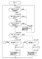
そこで、次にシステムコントローラ51による電動モータ39の回転数制御処理について、図7を処理プログラムに従って説明する。
Then, the rotational speed control processing of the
まず、処理動作がスタートすると、ステップ1で走行モードスイッチ19がオンになって高速選択部19Aが選択されているか否かを判定する。ステップ1で「NO」と判定したときには、走行モードスイッチ19がオフになって低速選択部19Bが選択されているから、ステップ2に移って、回転数設定ダイヤル22によって設定された設定回転数Nsで電動モータ39を回転させる。
First, when the processing operation starts, it is determined in
このとき、設定回転数Nsは、予め決められた最小回転数Nmin(例えばNmin=1300rpm)以上で、かつ最大回転数Nmax(例えばNmax=2400rpm)よりも低速な所定回転数N0(例えばN0=1800rpm)以下の範囲で設定されるものである。 At this time, the set rotational speed Ns is equal to or higher than a predetermined minimum rotational speed Nmin (for example, Nmin = 1300 rpm) and lower than the maximum rotational speed Nmax (for example, Nmax = 2400 rpm). ) It is set within the following range.
一方、ステップ1で「YES」と判定したときには、ステップ3に移って省エネモードスイッチ20がオンか否かを判定する。ステップ3で「YES」と判定したときには、ステップ2に移って、設定回転数Nsで電動モータ39を回転させる。
On the other hand, when “YES” is determined in
ステップ3で「NO」と判定したときには、省エネモード以外の通常モードまたはパワーモードが選択されているから、ステップ4に移って、バッテリコントローラ49からの検出信号を用いてメインバッテリ40に異常があるか否かを判定する。ステップ4で「YES」と判定したときには、メインバッテリ40に電圧低下等の異常が生じているから、電圧異常ランプ28を点灯させ、警報音等によってオペレータに注意を喚起すると共に、ステップ2に移って、設定回転数Nsで電動モータ39を回転させる。
If “NO” is determined in step 3, the normal mode or power mode other than the energy saving mode is selected, so the process proceeds to step 4, and the
一方、ステップ4で「NO」と判定したときには、電圧正常ランプ27を点灯させると共に、ステップ5に移ってパワーモードスイッチ21がオンか否かを判定する。ステップ5で「NO」と判定したときには、通常モードが選択されているから、ステップ6に移って走行レバー・ペダル装置29の操作量θが第1のしきい値Hよりも大きいか否かを判定する。
On the other hand, if “NO” is determined in
このとき、第1のしきい値Hは、操作量θに応じて電動モータ39の回転数Nを自動的に上昇させるか否かの判定に用いるものであり、例えば走行レバー・ペダル装置29の中立位置と最大傾転位置との中間位置よりも最大傾転位置側となる値に設定されている。
At this time, the first threshold value H is used to determine whether or not the rotational speed N of the
なお、第1のしきい値Hは、図8に示すように、チャタリングを防止するためのヒステリシス特性を有する。具体的には、操作量θが増加する傾転操作時には、第1のしきい値Hは、立上り判定値H1に設定される。これに対し、操作量θが減少する戻し操作時には、第1のしきい値Hは、立上り判定値H1よりも小さい値の立下り判定値H2に設定される。 The first threshold value H has a hysteresis characteristic for preventing chattering as shown in FIG. Specifically, at the time of the tilting operation in which the operation amount θ increases, the first threshold value H is set to the rising determination value H1. On the other hand, at the time of the return operation in which the operation amount θ decreases, the first threshold value H is set to the falling determination value H2 having a value smaller than the rising determination value H1.
そして、ステップ6で「NO」と判定したときには、走行レバー・ペダル装置29の操作量θが第1のしきい値Hよりも小さいから、ステップ7に移って、設定回転数Nsで電動モータ39を回転させる。
When the determination at step 6 is “NO”, the operation amount θ of the travel lever /
一方、ステップ6で「YES」と判定したときには、走行レバー・ペダル装置29の操作量θが第1のしきい値Hよりも大きくなっているから、オペレータは高速での車両の走行を要求しているものと考えられる。このため、ステップ8に移って、電動モータ39の回転数Nを上昇させて、最大回転数Nmaxで回転させる。
On the other hand, when “YES” is determined in step 6, since the operation amount θ of the travel lever /
また、ステップ5で「YES」と判定したときには、パワーモードが選択されているから、ステップ9に移って走行レバー・ペダル装置29の操作量θが第2のしきい値Lよりも大きいか否かを判定する。
If “YES” is determined in step 5, the power mode is selected, so the process proceeds to step 9 and whether or not the operation amount θ of the travel lever /
このとき、第2のしきい値Lは、操作量θに応じて電動モータ39の回転数Nを自動的に上昇させるか否かの判定に用いるものであり、第1のしきい値Hよりも小さい値(L<H)に設定されている。また、第2のしきい値Lも、第1のしきい値Hと同様に、図9に示すようなヒステリシス特性を有する。具体的には、操作量θが増加する傾転操作時には、第2のしきい値Lは、立上り判定値L1に設定される。これに対し、操作量θが減少する戻し操作時には、第2のしきい値Lは、立上り判定値L1よりも小さい値の立下り判定値L2に設定される。
At this time, the second threshold value L is used to determine whether or not the rotational speed N of the
そして、ステップ9で「NO」と判定したときには、走行レバー・ペダル装置29の操作量θが第2のしきい値Lよりも小さいから、ステップ7に移って、設定回転数Nsで電動モータ39を回転させる。
When the determination at
一方、ステップ9で「YES」と判定したときには、走行レバー・ペダル装置29の操作量θが第2のしきい値Lよりも大きくなっているから、ステップ8に移って、電動モータ39の回転数Nを上昇させて、最大回転数Nmaxで回転させる。そして、ステップ2,7,8が終了すると、ステップ1に戻り、ステップ1以降の処理を繰り返す。
On the other hand, when “YES” is determined in
次に、省エネモード、通常モード、パワーモードでの電動モータ39の回転数制御処理を行ったときの具体例について、図10ないし図12を参照しつつ説明する。
Next, a specific example when the rotational speed control process of the
図10に示す省エネモードでは、省エネモードスイッチ20がオンになっているから、システムコントローラ51は、インバータ42を制御して、回転数設定ダイヤル22によって設定された設定回転数Nsで電動モータ39を回転させる。この場合、走行レバー・ペダル装置29の操作量θを変化させても、電動モータ39の回転数Nは設定回転数Nsに保持される。また、省エネモードでは、設定回転数Nsは、最大回転数Nmaxよりも低速な所定回転数N0と最小回転数Nminとの間の範囲で設定される。図10は、設定回転数Nsが最小回転数Nminに設定された場合を示している。
In the energy saving mode shown in FIG. 10, since the energy saving
そして、電動モータ39および油圧ポンプ33は設定回転数Nsで回転すると共に、油圧ポンプ33は設定回転数Nsに応じた圧油を吐出する。これにより、走行モータ36は、油圧ポンプ33からの圧油の流量に応じて回転駆動し、車両を走行させる。
The
図11に示す通常モードでは、省エネモードスイッチ20とパワーモードスイッチ21はいずれもオフになっている。また、図11は、走行モードスイッチ19はオンになり、高速選択部19Aが選択された状態を示している。このため、走行モータ36の容量可変部36Aは小容量位置に設定されている。
In the normal mode shown in FIG. 11, both the energy saving
この通常モードでは、システムコントローラ51は、走行レバー・ペダル装置29の操作量θに応じて電動モータ39の回転数Nを自動的に変化させる。具体的に説明すると、走行レバー・ペダル装置29が中立位置にあるときには、システムコントローラ51は、インバータ42を制御して、回転数設定ダイヤル22によって設定された設定回転数Nsで電動モータ39を回転させる。通常モードでは、省エネモードと同様に、設定回転数Nsは、最大回転数Nmaxよりも低速な所定回転数N0と最小回転数Nminとの間の範囲で設定される。図11は、設定回転数Nsが最小回転数Nminに設定された場合を示している。
In this normal mode, the
次に、オペレータが走行レバー・ペダル装置29を走行操作して操作量θが第1のしきい値H(立上り判定値H1)を超えると(θ>H1)、システムコントローラ51は、インバータ42を制御して、電動モータ39の回転数Nを上昇させる。これにより、電動モータ39および油圧ポンプ33は最大回転数Nmaxで回転すると共に、油圧ポンプ33からの圧油の流量に応じて走行モータ36の回転速度が増速し、車両は高速走行する。
Next, when the operator operates the traveling lever /
また、オペレータが走行レバー・ペダル装置29を戻し操作して操作量θが第1のしきい値H(立下り判定値H2)よりも小さくなると(θ<H2)、システムコントローラ51は、インバータ42を制御して、電動モータ39の回転数Nを低下させる。これにより、電動モータ39および油圧ポンプ33は設定回転数Nsで回転すると共に、油圧ポンプ33からの圧油の流量に応じて走行モータ36の回転速度が減速し、車両の走行速度は低下する。
Further, when the operator returns the traveling lever /
図12に示すパワーモードでは、パワーモードスイッチ21はオンになっている。また、図12は、図11と同様に、走行モードスイッチ19はオンになり、高速選択部19Aが選択された状態を示している。このため、走行モータ36の容量可変部36Aは小容量位置に設定されている。
In the power mode shown in FIG. 12, the
このパワーモードでも、図11に示す通常モードと同様に、システムコントローラ51は、走行レバー・ペダル装置29の操作量θに応じて電動モータ39の回転数Nを自動的に変化させる。具体的に説明すると、走行レバー・ペダル装置29が中立位置にあるときには、システムコントローラ51は、インバータ42を制御して、回転数設定ダイヤル22によって設定された設定回転数Nsで電動モータ39を回転させる。
Also in this power mode, as in the normal mode shown in FIG. 11, the
但し、パワーモードでは、通常モードに比べて、設定回転数Nsを高速な値に設定することができる。即ち、パワーモードでは、通常モードおよび省エネモードとは異なり、設定回転数Nsは、最大回転数Nmaxと最小回転数Nminとの間の範囲で設定可能となる。このため、パワーモードの設定回転数Nsは、通常モードでの上限値となる所定回転数N0よりも高速な値に設定することができる。図12は、設定回転数Nsが、所定回転数N0となる1800rpmよりも高速な2200rpmに設定された場合を示している。 However, in the power mode, the set rotational speed Ns can be set to a higher value than in the normal mode. That is, in the power mode, unlike the normal mode and the energy saving mode, the set rotational speed Ns can be set in a range between the maximum rotational speed Nmax and the minimum rotational speed Nmin. For this reason, the set rotational speed Ns in the power mode can be set to a value faster than the predetermined rotational speed N0 that is the upper limit value in the normal mode. FIG. 12 shows a case where the set rotational speed Ns is set to 2200 rpm, which is faster than 1800 rpm, which is the predetermined rotational speed N0.
次に、オペレータが走行レバー・ペダル装置29を走行操作して操作量θが第2のしきい値L(立上り判定値L1)を超えると(θ>L1)、システムコントローラ51は、インバータ42を制御して、電動モータ39の回転数Nを上昇させる。これにより、電動モータ39および油圧ポンプ33は最大回転数Nmaxで回転すると共に、油圧ポンプ33からの圧油の流量に応じて走行モータ36の回転速度が増速し、車両は高速走行する。
Next, when the operator operates the travel lever /
このとき、パワーモードによる第2のしきい値Lは、通常モードによる第1のしきい値Hよりも小さい値に設定されている。このため、パワーモードでは、通常モードに比べて、小さい操作量θで電動モータ39の回転数Nを上昇させることができる。
At this time, the second threshold value L in the power mode is set to a value smaller than the first threshold value H in the normal mode. For this reason, in the power mode, the rotational speed N of the
また、オペレータが走行レバー・ペダル装置29を戻し操作して操作量θが第2のしきい値L(立下り判定値L2)よりも小さくなると(θ<L2)、システムコントローラ51は、インバータ42を制御して、電動モータ39の回転数Nを低下させる。これにより、電動モータ39および油圧ポンプ33は設定回転数Nsで回転すると共に、油圧ポンプ33からの圧油の流量に応じて走行モータ36の回転速度が減速し、車両の走行速度は低下する。
When the operator returns the traveling lever /
かくして、本実施の形態によれば、システムコントローラ51は、省エネモードスイッチ20がオンになった省エネモードでは、走行レバー・ペダル装置29の走行操作に関係なく回転数設定ダイヤル22によって設定された設定回転数Nsで電動モータ39を駆動させる。このため、車両を停止させた状態で掘削作業等を行うときには、設定回転数Nsを例えば最小回転数Nminに設定することによって、メインバッテリ40の電力消費を確実に抑えることができ、油圧ショベル1の稼動時間を長くすることができる。
Thus, according to the present embodiment, in the energy saving mode in which the energy saving
一方、省エネモードスイッチがオフになった通常モードやパワーモードでは、システムコントローラ51は、走行モードスイッチ19の高速選択部19Aが選択された状態で、走行レバー・ペダル装置29が中立位置にあるときに回転数設定ダイヤル22によって設定された設定回転数Nsで電動モータ39を駆動させ、走行レバー・ペダル装置29を走行操作したときに電動モータ39の回転数Nを上昇させる。これにより、車両を走行させるときに、オペレータが予め走行モードスイッチ19をオンにして高速側を選択しておけば、走行レバー・ペダル装置29の走行操作を行うだけで電動モータ39の回転数Nを自動的に上昇させることができる。また、走行レバー・ペダル装置29が中立位置に戻ったときには電動モータ39の回転数Nを設定回転数Nsまで自動的に低下させることができる。このため、例えば車両を高速走行させるときでも、電動モータ39の回転数Nを上昇させるための特別な操作が必要なく、走行レバー・ペダル装置29を走行操作するだけでよいため、操作を簡略化して作業性を高めることができる。
On the other hand, in the normal mode or power mode in which the energy saving mode switch is turned off, the
また、回転数設定ダイヤル22は、パワーモードスイッチ21がオンの場合には、設定回転数Nsを電動モータ39の最大回転数Nmax以下の範囲で設定可能とした。このため、例えば重負荷での掘削作業を行う場合には、オペレータがパワーモードスイッチ21をオンにすれば、走行レバー・ペダル装置29が中立位置にあるときでも、最大回転数Ns以下の範囲でオペレータによって設定された高速な設定回転数Nsで電動モータ39を駆動させることができ、重負荷に対応した圧油を各シリンダ9〜11に供給することができる。
Further, the rotation
また、回転数設定ダイヤル22は、パワーモードスイッチ21がオフの場合には、設定回転数Nsを電動モータ39の最大回転数Nmaxに比べて低速な所定回転数N0以下の範囲で設定可能とした。このため、軽負荷時には、設定回転数Nsは最大回転数Nmaxに比べて低速な所定回転数N0以下の値に設定されるから、電動モータ39の回転数Nを低下させてメインバッテリ40の電力消費を抑制することができる。
Further, when the
また、システムコントローラ51は、省エネモードスイッチ20およびパワーモードスイッチ21のいずれもオフとなる通常モードでは、走行レバー・ペダル装置29の操作量θが予め決められた第1のしきい値Hを超えたときに電動モータ39の回転数Nを上昇させる構成とした。このため、通常モードでは、走行レバー・ペダル装置29の操作量θが第1のしきい値Hよりも小さいときには、電動モータ39の回転数Nは設定回転数Nsに維持する。このとき、電動モータ39によって駆動する油圧ポンプ33は、車両の低速走行に応じた圧油を走行モータ36に供給する。また、走行レバー・ペダル装置29の操作量θが第1のしきい値Hよりも大きいときには、電動モータ39の回転数Nを上昇させる。これにより、電動モータ39によって駆動する油圧ポンプ33は、車両の高速走行に応じた圧油を走行モータ36に供給することができる。
Further, in the normal mode in which both the energy saving
一方、システムコントローラ51は、パワーモードスイッチ21がオンとなるパワーモードでは、第2のしきい値Lを超えて走行レバー・ペダル装置29を走行操作したときに電動モータ39の回転数Nを上昇させる構成とした。このため、パワーモードでは、走行レバー・ペダル装置29の操作量θが第2のしきい値Lよりも小さいときには、電動モータ39の回転数Nは設定回転数Nsに維持する。また、走行レバー・ペダル装置29の操作量θが第2のしきい値Lよりも大きいときには、電動モータ39の回転数Nを上昇させる。これにより、電動モータ39によって駆動する油圧ポンプ33は、通常モードと同様に、車両の走行速度に応じた圧油を走行モータ36に供給することができる。
On the other hand, in the power mode in which the
さらに、第2のしきい値Lは第1のしきい値Hよりも小さい値となっている。このため、パワーモードでは、通常モードに比べて小さい操作量θで、電動モータ39の回転数Nを上昇させるから、速やかに車両を高速走行させることができる。
Furthermore, the second threshold value L is smaller than the first threshold value H. For this reason, in the power mode, the rotational speed N of the
また、走行モードスイッチ19、省エネモードスイッチ20、パワーモードスイッチ21および回転数設定ダイヤル22は、運転席12の横脇に配置されたコンソール16に取り付ける構成とした。このため、オペレータは、運転席12に着座した状態で、走行モードスイッチ19、省エネモードスイッチ20、パワーモードスイッチ21および回転数設定ダイヤル22を操作することができ、省エネモード、通常モード、パワーモードを速やかに切換えることができる。
Further, the
さらに、システムコントローラ51は、バッテリコントローラ49によってメインバッテリ20の異常を検出したときには、走行レバー・ペダル装置29の走行操作に拘らず回転数設定ダイヤル22によって設定された設定回転数Nsで電動モータ39を駆動させる構成とした。このため、例えばメインバッテリ40の充電不足等のように、電動モータ39を高速回転で駆動させることが不適切な状況では、電動モータ39の回転数Nを設定回転数Nsに維持することができる。
Further, when the
なお、前記実施の形態では、図7中のステップ2,3が省エネモード駆動装置の具体例を示し、ステップ4〜8が非省エネモード駆動装置の具体例を示している。また、図7中のステップ5〜8が通常モード処理装置の具体例を示し、図7中のステップ5,7〜9がパワーモード処理装置の具体例を示し、図7中のステップ4,2がバッテリ異常処理装置の具体例を示している。
In the above embodiment, steps 2 and 3 in FIG. 7 show a specific example of the energy saving mode driving device, and
また、前記実施の形態では、省エネモードスイッチ20、パワーモードスイッチ21のオン/オフに応じて切換わる省エネモード、通常モード、パワーモードの3つの動作モードを備える構成とした。しかし、本発明はこれに限らず、例えばパワーモードスイッチ21を省き、省エネモードスイッチ20だけで切換わる省エネモード、通常モードの2つの動作モードだけを備える構成としてもよい。この場合、通常モードでは、設定回転数Nsは最大回転数Nmaxまで設定可能な構成としてもよい。
Moreover, in the said embodiment, it was set as the structure provided with three operation modes, the energy saving mode switched according to ON / OFF of the energy saving
また、前記実施の形態では、メインバッテリ40とインバータ42との間には昇圧回路および降圧回路を兼用する昇降圧チョッパ46を設ける構成とした。しかし、本発明はこれに限らず、昇圧回路および降圧回路を別途に設ける構成としてもよい。
In the above embodiment, the step-up / step-down
また、前記実施の形態では、メインバッテリ40は160VDCの直流電圧を出力すると共に、電動モータ39は200VACの三相交流電力によって駆動するものとした。しかし、これらの電圧値は、実施の形態で示した値に限らず、各バッテリや電動モータの仕様等に応じて適宜設定すればよい。
In the embodiment, the
さらに、前記実施の形態では、電動式建設機械として装軌式の油圧ショベルを例に挙げて説明したが、本発明はこれに限らず、例えばホイール式の油圧ショベル等のように油圧ポンプを用いて走行する他の建設機械にも広く適用することができる。 Furthermore, in the above-described embodiment, a track-type hydraulic excavator has been described as an example of the electric construction machine. However, the present invention is not limited thereto, and a hydraulic pump such as a wheel-type hydraulic excavator is used. It can be widely applied to other construction machines that run on the road.
2 下部走行体
3 上部旋回体
12 運転席
16 右側コンソール(コンソール)
19 走行モードスイッチ
20 省エネモードスイッチ
21 パワーモードスイッチ
22 回転数設定ダイヤル(回転数設定器)
29 走行レバー・ペダル装置(走行操作装置)
33 油圧ポンプ
36 走行モータ(走行用油圧モータ)
38 走行速度切換電磁弁(容量切換弁)
39 電動モータ
40 メインバッテリ
42 インバータ
46 昇降圧チョッパ(昇圧回路)
49 バッテリコントローラ
51 システムコントローラ(回転数制御装置)
2 Lower traveling body 3
19
29 Traveling lever / pedal device (traveling operation device)
33
38 Traveling speed switching solenoid valve (capacity switching valve)
39
49
Claims (5)
該車体に設けられたメインバッテリと、
該メインバッテリから供給される直流電圧を昇圧する昇圧回路と、
該昇圧回路から供給される直流電力を交流電力に変換するインバータと、
該インバータから供給される交流電力によって駆動する電動モータと、
該電動モータによって駆動する油圧ポンプと、
該油圧ポンプによる油圧を用いて駆動し、容量切換弁による容量の切換えに応じて前記車体を高速または低速で走行させる可変容量型の走行用油圧モータと、
前記車体に設けられ、オペレータの走行操作に応じて該走行用油圧モータを制御するための走行操作装置と、
前記走行用油圧モータの容量切換弁を切換え操作して前記車体の走行速度として高速および低速のいずれかを選択する走行モードスイッチと、
前記電動モータの回転数を設定する回転数設定器と、
前記メインバッテリの電力消費を抑制するための省エネモードスイッチと、
前記走行モードスイッチおよび該省エネモードスイッチに応じて前記インバータを制御し、前記電動モータの回転数を制御する回転数制御装置とを備え、
前記回転数制御装置は、前記省エネモードスイッチを省エネモードに切換えた場合に、前記走行操作装置の走行操作に拘らず前記回転数設定器によって設定された設定回転数で前記電動モータを駆動させる省エネモード駆動装置と、
前記省エネモードスイッチを非省エネモードに切換えた場合に、前記走行モードスイッチによって高速側が選択された状態で、前記走行操作装置が中立位置にあるときに前記回転数設定器によって設定された設定回転数で前記電動モータを駆動させ、前記走行操作装置を走行操作したときに前記電動モータの回転数を上昇させる非省エネモード駆動装置とを備える構成としてなる電動式建設機械。 A self-propelled vehicle body with a driver's seat,
A main battery provided on the vehicle body;
A booster circuit for boosting a DC voltage supplied from the main battery;
An inverter that converts DC power supplied from the booster circuit to AC power;
An electric motor driven by AC power supplied from the inverter;
A hydraulic pump driven by the electric motor;
A variable displacement travel hydraulic motor that is driven by the hydraulic pressure of the hydraulic pump, and that travels the vehicle body at a high speed or a low speed in accordance with a change of capacity by a capacity switching valve;
A travel operation device provided on the vehicle body for controlling the travel hydraulic motor in accordance with a travel operation of an operator;
A travel mode switch for switching between a capacity switching valve of the travel hydraulic motor and selecting either high speed or low speed as the travel speed of the vehicle body;
A rotational speed setter for setting the rotational speed of the electric motor;
An energy saving mode switch for suppressing power consumption of the main battery;
A rotation speed control device that controls the inverter according to the travel mode switch and the energy saving mode switch, and controls the rotation speed of the electric motor;
When the energy saving mode switch is switched to the energy saving mode, the rotation speed control device saves energy by driving the electric motor at the set rotation speed set by the rotation speed setting device regardless of the travel operation of the travel operation device. A mode drive;
When the energy-saving mode switch is switched to the non-energy-saving mode, the set rotational speed set by the rotational speed setter when the traveling operation device is in the neutral position with the high-speed side selected by the traveling mode switch An electric construction machine comprising: a non-energy-saving mode drive device that drives the electric motor to increase the rotation speed of the electric motor when the travel operation device is traveled.
前記回転数設定器は、該パワーモードスイッチをパワーモードに切換えた場合には、前記設定回転数を前記電動モータの最大回転数以下の範囲で設定可能とし、該パワーモードスイッチを非パワーモードに切換えた場合には、前記設定回転数を前記電動モータの最大回転数に比べて低速な所定回転数以下の範囲で設定可能とする請求項1に記載の電動式建設機械。 A power mode switch that enables the electric motor to be driven at a maximum rotational speed when the travel operation device is in a neutral position;
When the power mode switch is switched to the power mode, the rotational speed setter enables the set rotational speed to be set within a range equal to or less than the maximum rotational speed of the electric motor, and the power mode switch is set to a non-power mode. 2. The electric construction machine according to claim 1, wherein, when switched, the set rotational speed can be set within a range of a predetermined rotational speed that is lower than a maximum rotational speed of the electric motor.
前記パワーモードスイッチをパワーモードに切換えた場合に、前記走行操作装置の操作量が前記第1のしきい値よりも小さい第2のしきい値を超えたときに前記電動モータの回転数を上昇させるパワーモード処理装置とを備える構成としてなる請求項2に記載の電動式建設機械。 The non-energy-saving mode drive device rotates the electric motor when the operation amount of the travel operation device exceeds a predetermined first threshold when the power mode switch is switched to the non-power mode. A normal mode processing device for increasing the number;
When the power mode switch is switched to the power mode, the rotational speed of the electric motor is increased when the operation amount of the traveling operation device exceeds a second threshold value that is smaller than the first threshold value. The electric construction machine according to claim 2, comprising a power mode processing device.
前記非省エネモード駆動装置は、該バッテリコントローラによって前記メインバッテリの異常を検出したときには、前記走行操作装置の走行操作に拘らず前記回転数設定器によって設定された設定回転数で前記電動モータを駆動させるバッテリ異常処理装置を備える構成としてなる請求項1,2,3または4に記載の電動式建設機械。 A battery controller for detecting an abnormality of the main battery;
When the battery controller detects an abnormality of the main battery by the battery controller, the non-energy-saving mode driving device drives the electric motor at the set rotational speed set by the rotational speed setter regardless of the traveling operation of the traveling operation device. The electric construction machine according to claim 1, 2, 3, or 4, comprising a battery abnormality processing device.
Priority Applications (1)
| Application Number | Priority Date | Filing Date | Title |
|---|---|---|---|
| JP2010050384A JP5390436B2 (en) | 2010-03-08 | 2010-03-08 | Electric construction machine |
Applications Claiming Priority (1)
| Application Number | Priority Date | Filing Date | Title |
|---|---|---|---|
| JP2010050384A JP5390436B2 (en) | 2010-03-08 | 2010-03-08 | Electric construction machine |
Publications (2)
| Publication Number | Publication Date |
|---|---|
| JP2011184922A JP2011184922A (en) | 2011-09-22 |
| JP5390436B2 true JP5390436B2 (en) | 2014-01-15 |
Family
ID=44791531
Family Applications (1)
| Application Number | Title | Priority Date | Filing Date |
|---|---|---|---|
| JP2010050384A Active JP5390436B2 (en) | 2010-03-08 | 2010-03-08 | Electric construction machine |
Country Status (1)
| Country | Link |
|---|---|
| JP (1) | JP5390436B2 (en) |
Cited By (1)
| Publication number | Priority date | Publication date | Assignee | Title |
|---|---|---|---|---|
| US11933024B2 (en) | 2020-02-27 | 2024-03-19 | Cnh Industrial America Llc | System and method for controlling pump operating speed range of an electric work vehicle based on hydraulic fluid pressure |
Families Citing this family (2)
| Publication number | Priority date | Publication date | Assignee | Title |
|---|---|---|---|---|
| JP2013234549A (en) * | 2012-05-11 | 2013-11-21 | Nakayama Iron Works Ltd | Self-propelled work machine |
| JP7451828B2 (en) | 2022-03-31 | 2024-03-18 | 日立建機株式会社 | electric hydraulic working machine |
Family Cites Families (1)
| Publication number | Priority date | Publication date | Assignee | Title |
|---|---|---|---|---|
| JP5113603B2 (en) * | 2008-04-18 | 2013-01-09 | 日立建機株式会社 | Electric work machine |
-
2010
- 2010-03-08 JP JP2010050384A patent/JP5390436B2/en active Active
Cited By (1)
| Publication number | Priority date | Publication date | Assignee | Title |
|---|---|---|---|---|
| US11933024B2 (en) | 2020-02-27 | 2024-03-19 | Cnh Industrial America Llc | System and method for controlling pump operating speed range of an electric work vehicle based on hydraulic fluid pressure |
Also Published As
| Publication number | Publication date |
|---|---|
| JP2011184922A (en) | 2011-09-22 |
Similar Documents
| Publication | Publication Date | Title |
|---|---|---|
| EP1834854B1 (en) | Hybrid construction machine | |
| JP5759019B1 (en) | Hybrid work machine | |
| JP5356423B2 (en) | Construction machine having a rotating body | |
| KR101834598B1 (en) | Hybrid construction machine | |
| KR101256483B1 (en) | Hybrid working machine | |
| US20130311052A1 (en) | Hybrid construction machine and auxiliary control device used therein | |
| KR101714948B1 (en) | Construction machine | |
| WO2013175658A1 (en) | Hybrid work machine and hybrid work machine control method | |
| JP5974014B2 (en) | Hybrid drive hydraulic work machine | |
| JP5384397B2 (en) | Electric construction machine | |
| KR102089992B1 (en) | Construction machinery | |
| JP4979529B2 (en) | Battery powered construction machinery | |
| WO2015170489A1 (en) | Hybrid work machine | |
| KR20140018346A (en) | Power shovel and power shovel control method | |
| JP5699155B2 (en) | Swiveling drive control device | |
| JP5390436B2 (en) | Electric construction machine | |
| JP6529721B2 (en) | Construction machinery | |
| CN106605028B (en) | Hybrid construction machine | |
| JP2014133455A (en) | Hydraulic pump drive device of construction machine | |
| KR20160140593A (en) | Shovel | |
| JP2002322926A (en) | Engine controller for hybrid construction machine | |
| JP2012233312A (en) | Hybrid work machine | |
| JP5808635B2 (en) | Control method of hybrid excavator | |
| WO2020039861A1 (en) | Hybrid construction machine | |
| JP6544285B2 (en) | Industrial vehicle |
Legal Events
| Date | Code | Title | Description |
|---|---|---|---|
| A621 | Written request for application examination |
Free format text: JAPANESE INTERMEDIATE CODE: A621 Effective date: 20120207 |
|
| A977 | Report on retrieval |
Free format text: JAPANESE INTERMEDIATE CODE: A971007 Effective date: 20130219 |
|
| TRDD | Decision of grant or rejection written | ||
| A01 | Written decision to grant a patent or to grant a registration (utility model) |
Free format text: JAPANESE INTERMEDIATE CODE: A01 Effective date: 20131001 |
|
| A61 | First payment of annual fees (during grant procedure) |
Free format text: JAPANESE INTERMEDIATE CODE: A61 Effective date: 20131010 |
|
| R150 | Certificate of patent or registration of utility model |
Ref document number: 5390436 Country of ref document: JP Free format text: JAPANESE INTERMEDIATE CODE: R150 Free format text: JAPANESE INTERMEDIATE CODE: R150 |
|
| S111 | Request for change of ownership or part of ownership |
Free format text: JAPANESE INTERMEDIATE CODE: R313113 |
|
| S531 | Written request for registration of change of domicile |
Free format text: JAPANESE INTERMEDIATE CODE: R313531 |
|
| R350 | Written notification of registration of transfer |
Free format text: JAPANESE INTERMEDIATE CODE: R350 |