JP5389965B2 - Scattered ray correction method and X-ray CT apparatus - Google Patents
Scattered ray correction method and X-ray CT apparatus Download PDFInfo
- Publication number
- JP5389965B2 JP5389965B2 JP2012037447A JP2012037447A JP5389965B2 JP 5389965 B2 JP5389965 B2 JP 5389965B2 JP 2012037447 A JP2012037447 A JP 2012037447A JP 2012037447 A JP2012037447 A JP 2012037447A JP 5389965 B2 JP5389965 B2 JP 5389965B2
- Authority
- JP
- Japan
- Prior art keywords
- information
- ray
- boundary
- projection
- scattered
- Prior art date
- Legal status (The legal status is an assumption and is not a legal conclusion. Google has not performed a legal analysis and makes no representation as to the accuracy of the status listed.)
- Expired - Fee Related
Links
- 238000000034 method Methods 0.000 title claims description 29
- 238000012545 processing Methods 0.000 claims description 43
- 238000010521 absorption reaction Methods 0.000 claims description 38
- 238000000605 extraction Methods 0.000 claims description 26
- 230000005855 radiation Effects 0.000 claims description 18
- 238000013480 data collection Methods 0.000 claims description 13
- 230000005540 biological transmission Effects 0.000 claims description 6
- 239000000284 extract Substances 0.000 claims description 4
- 239000013256 coordination polymer Substances 0.000 description 14
- 238000010586 diagram Methods 0.000 description 14
- 238000007781 pre-processing Methods 0.000 description 13
- 238000012805 post-processing Methods 0.000 description 12
- 238000003384 imaging method Methods 0.000 description 6
- 239000011159 matrix material Substances 0.000 description 2
- 238000006243 chemical reaction Methods 0.000 description 1
- 239000013078 crystal Substances 0.000 description 1
- 238000001514 detection method Methods 0.000 description 1
- 230000002542 deteriorative effect Effects 0.000 description 1
- 238000010606 normalization Methods 0.000 description 1
- 230000002093 peripheral effect Effects 0.000 description 1
- 230000035945 sensitivity Effects 0.000 description 1
Images


Landscapes
- Apparatus For Radiation Diagnosis (AREA)
Description
この発明は、被検体に照射されるX線ビーム(beam)の散乱線を補正する散乱線補正方法およびX線CT装置に関する。 The present invention relates to a scattered radiation correction method and an X-ray CT apparatus for correcting scattered radiation of an X-ray beam (beam) irradiated on a subject.
近年、X線CT装置の普及により、X線CT装置で取得される断層画像情報に求められる画質は、ますます高品質なものとなりつつある。ここで、X線CT画像の画質改善の方法として、例えば、被検体内部で生じる散乱X線の補正を行うことが挙げられる。 In recent years, with the widespread use of X-ray CT apparatuses, the image quality required for tomographic image information acquired by X-ray CT apparatuses is becoming increasingly high quality. Here, as a method for improving the image quality of the X-ray CT image, for example, correction of scattered X-rays generated inside the subject can be mentioned.
この方法によれば、理論的あるいは実験的に求められる散乱X線量が、被検体の投影情報から除去される。そして、画像再構成の基となる投影情報は、透過X線ビームのみからなる様にされる。 According to this method, the scattered X-ray dose determined theoretically or experimentally is removed from the projection information of the subject. The projection information that is the basis of image reconstruction is made up of only the transmitted X-ray beam.
ここで、被検体の散乱X線量は、被検体の中を透過するX線ビームの透過距離(以下、投影長と称する)に比例して大きなものとなる。従って、散乱X線の補正を行う場合にも、この投影長を考慮し、投影長が長い場合、言い換えれば被検体が投影方向に大きな厚みを有する場合には、補正される散乱X線量も大きなものとなる。 Here, the scattered X-ray dose of the subject increases in proportion to the transmission distance of the X-ray beam that passes through the subject (hereinafter referred to as the projection length). Therefore, even when correcting the scattered X-rays, if this projection length is taken into consideration and the projection length is long, in other words, if the subject has a large thickness in the projection direction, the corrected scattered X-ray dose is also large. It will be a thing.
しかしながら、上記背景技術によれば、投影長に基づいた散乱X線の補正は、充分なものではない。すなわち、X線ビームが透過する経路上に、X線吸収率が変化する境界が存在する場合には、均一な媒質中で生じるX線ビームの散乱とは異なる現象が起こり、投影長を考慮するだけでは補正されない。 However, according to the above background art, correction of scattered X-rays based on the projection length is not sufficient. That is, when a boundary where the X-ray absorption rate changes exists on the path through which the X-ray beam passes, a phenomenon different from the X-ray beam scattering that occurs in a uniform medium occurs, and the projection length is taken into consideration. It is not corrected only by itself.
特に、画像再構成により断層画像を形成する際に、X線吸収率が変化する境界近傍の画像にアーチファクト(artifact)を生じさせることがある。このアーチファクトは、断層画像の品質を低下させる要因ともなり、好ましいものではない。 In particular, when a tomographic image is formed by image reconstruction, an artifact may be generated in an image near the boundary where the X-ray absorption rate changes. This artifact becomes a factor of deteriorating the quality of the tomographic image and is not preferable.
これらのことから、被検体のX線吸収率が変化する境界を含む場合の散乱線補正方法およびX線CT装置をいかに実現するかが重要となる。 From these facts, it is important how to realize the scattered radiation correction method and the X-ray CT apparatus when the boundary including the X-ray absorption rate of the subject is changed.
この発明は、上述した背景技術による課題を解決するためになされたものであり、被検体のX線吸収率が変化する境界を含む場合の散乱線補正方法およびX線CT装置を提供することを目的とする。 The present invention has been made in order to solve the above-described problems caused by the background art, and provides a scattered radiation correction method and an X-ray CT apparatus in the case of including a boundary where the X-ray absorption rate of a subject changes. Objective.
上述した課題を解決し、目的を達成するために、第1の観点の発明にかかる散乱線補正方法は、被検体のX線投影情報または前記投影情報を画像再構成して生成される断層画像情報を用いて、前記被検体内部の境界位置を含むX線吸収率が変化する境界位置の境界位置情報および前記変化の大きさを示す大きさ情報を含む境界情報を抽出し、前記境界情報を含む情報に基づいて求められた前記投影情報または前記断層画像情報における散乱X線補正量を用いて、前記投影情報または前記断層画像情報を補正することを特徴とする。 In order to solve the above-described problems and achieve the object, the scattered radiation correction method according to the first aspect of the invention is an X-ray projection information of a subject or a tomographic image generated by image reconstruction of the projection information. Using the information, the boundary position information including the boundary position including the boundary position inside the subject and the boundary position information including the boundary position information indicating the magnitude of the change is extracted. The projection information or the tomographic image information is corrected using the scattered X-ray correction amount in the projection information or the tomographic image information obtained based on the information included.
また、第2の観点の発明にかかる散乱性補正方法は、第1の観点に記載の散乱線補正方法において、前記散乱X線補正量は、前記被検体を通過するX線の透過長にも基づくことを特徴とする。 Further, the scattering correction method according to the invention of the second aspect is the scattered radiation correction method according to the first aspect, wherein the amount of scattered X-ray correction is also the transmission length of X-rays passing through the subject. Based on.
また、第3の観点の発明にかかる散乱性補正方法は、第1または第2の観点に記載の散乱線補正方法において、前記補正は、前記投影情報または前記断層画像情報における散乱X線補正量を、前記投影情報または前記断層画像情報から減算して行う補正であることを特徴とする。 The scattering correction method according to the invention of the third aspect is the scattered radiation correction method according to the first or second aspect, wherein the correction is a scattered X-ray correction amount in the projection information or the tomographic image information. Is a correction performed by subtracting from the projection information or the tomographic image information.
また、第4の観点の発明にかかる散乱性補正方法は、第1から第3のいずれか一つの観点に記載の散乱線補正方法において、前記抽出は、前記投影情報の投影値を、前記投影情報を取得するX線検出器のチャネル方向及び/又は列方向に対応する方向に微分し、前記微分された微分値の大きさが閾値を越える位置を前記境界位置情報として抽出し、前記微分値の大きさを前記大きさ情報として抽出することを特徴とする。 The scattering correction method according to the invention of a fourth aspect is the scattered radiation correction method according to any one of the first to third aspects, wherein the extraction is performed by using a projection value of the projection information as the projection. Differentiating in the direction corresponding to the channel direction and / or column direction of the X-ray detector for acquiring information, extracting the position where the magnitude of the differentiated differential value exceeds a threshold value as the boundary position information, the differential value Is extracted as the size information.
また、第5の観点の発明にかかる散乱性補正方法は、第1から第3のいずれか一つの観点に記載の散乱線補正方法において、前記抽出は、前記断層画像情報の断層画像を微分処理し、前記微分処理された微分画像を絶対値処理して境界画像を作成し、前記境界画像を用いて前記境界情報を抽出することを特徴とする。 The scattering correction method according to the invention of the fifth aspect is the scattered radiation correction method according to any one of the first to third aspects, wherein the extraction is a differential processing of the tomographic image of the tomographic image information. The differential image subjected to the differential processing is subjected to absolute value processing to create a boundary image, and the boundary information is extracted using the boundary image.
また、第6の観点の発明にかかる散乱性補正方法は、第5の観点に記載の散乱線補正方法において、前記抽出は、前記境界画像を用いて境界投影情報を算出し、前記境界投影情報の境界投影値が零でない位置を境界位置情報として抽出し、前記境界投影値を前記大きさ情報として抽出することを特徴とする。 The scattering correction method according to the invention of a sixth aspect is the scattered radiation correction method according to the fifth aspect, wherein the extraction calculates boundary projection information using the boundary image, and the boundary projection information A position where the boundary projection value is not zero is extracted as boundary position information, and the boundary projection value is extracted as the size information.
また、第7の観点の発明にかかる散乱性補正方法は、第1から第6のいずれか一つの観点に記載の散乱線補正方法において、前記補正は、前記大きさ情報の多次関数からなるゲイン関数を用いることを特徴とする。 Further, the scattering correction method according to the seventh aspect of the invention is the scattered radiation correction method according to any one of the first to sixth aspects, wherein the correction comprises a multi-order function of the magnitude information. A gain function is used.
また、第8の観点の発明にかかる散乱性補正方法は、第7の観点に記載の散乱線補正方法において、前記補正は、前記投影情報または前記断層画像情報における前記境界位置での散乱X線量に前記ゲイン関数の関数値を乗算し、前記乗算された散乱X線量を前記投影情報または前記断層画像情報から減算することを特徴とする。 Further, the scatter correction method according to the invention of the eighth aspect is the scattered radiation correction method according to the seventh aspect, wherein the correction is a scattered X-ray dose at the boundary position in the projection information or the tomographic image information. Is multiplied by the function value of the gain function, and the multiplied scattered X-ray dose is subtracted from the projection information or the tomographic image information.
また、第9の観点の発明にかかるX線CT装置は、X線発生装置と、前記X線発生装置を対向して配置されたX線検出器とを、被検体の周りを相対回転させてX線投影データを収集するX線データ収集手段と、前記X線投影データを用いて被検体の画像情報を生成する画像情報生成手段とを有するX線CT装置において、前記画像生成手段は、被検体のX線投影情報または前記投影情報を画像再構成して生成される断層画像情報を用いて、前記被検体内部の境界位置を含むX線吸収率が変化する境界位置の境界位置情報および前記変化の大きさを示す大きさ情報を含む境界情報を抽出する手段と、前記境界情報を含む情報に基づいて求められた前記投影情報または前記断層画像情報における散乱X線補正量を用いて、前記投影情報または前記断層画像情報を補正する補正手段とを含むことを特徴とする。 An X-ray CT apparatus according to the ninth aspect of the invention is configured to relatively rotate an X-ray generator and an X-ray detector disposed so as to face the X-ray generator around the subject. In an X-ray CT apparatus having an X-ray data collection unit for collecting X-ray projection data and an image information generation unit for generating image information of a subject using the X-ray projection data, the image generation unit includes: Using the X-ray projection information of the specimen or tomographic image information generated by reconstructing the projection information, the boundary position information of the boundary position where the X-ray absorption rate including the boundary position inside the subject changes, and the The means for extracting boundary information including size information indicating the magnitude of change, and the scattered X-ray correction amount in the projection information or tomographic image information obtained based on the information including the boundary information, Projection information or said Characterized in that it comprises a correction means for correcting the layer image information.
また、第10の観点の発明にかかるX線CT装置は、第9の観点に記載のX線CT装置において、前記散乱X線補正量は、前記被検体を通過するX線の透過長にも基づくことを特徴とする。 The X-ray CT apparatus according to the invention of the tenth aspect is the X-ray CT apparatus according to the ninth aspect, wherein the scattered X-ray correction amount is also determined by a transmission length of X-rays passing through the subject. Based on.
また、第11の観点の発明にかかるX線CT装置は、第9または第10の観点に記載のX線CT装置において、前記補正は、前記投影情報または前記断層画像情報における散乱X線補正量を、前記投影情報または前記断層画像情報から減算して行う補正であることを特徴とする。 An X-ray CT apparatus according to an eleventh aspect of the invention is the X-ray CT apparatus according to the ninth or tenth aspect, wherein the correction is a scattered X-ray correction amount in the projection information or the tomographic image information. Is a correction performed by subtracting from the projection information or the tomographic image information.
また、第12の観点の発明にかかるX線CT装置は、第9から第10のいずれか一つの観点に記載のX線CT装置において、前記境界情報を抽出する手段は、前記抽出は、前記投影情報の投影値を前記投影情報を取得するX線検出器のチャネル方向及び/又は列方向に対応する方向に微分し、前記微分された微分値の大きさが閾値を越える位置を前記境界位置情報として抽出する手段を含むことを特徴とする。 An X-ray CT apparatus according to the invention of a twelfth aspect is the X-ray CT apparatus according to any one of the ninth to tenth aspects, wherein the means for extracting the boundary information is the extraction Differentiating the projection value of the projection information in a direction corresponding to the channel direction and / or the column direction of the X-ray detector for acquiring the projection information, and the position where the magnitude of the differentiated differential value exceeds a threshold value is the boundary position It includes a means for extracting as information.
また、第12の観点の発明にかかるX線CT装置は、第9から第11のいずれか一つの観点に記載のX線CT装置において、前記境界情報を抽出する手段は、記断層画像情報の断層画像を微分処理し、前記微分処理された微分画像を絶対値処理して境界画像を作成し、前記境界画像を用いて前記境界情報を抽出する手段を含むことを特徴とする。 An X-ray CT apparatus according to a twelfth aspect of the present invention is the X-ray CT apparatus according to any one of the ninth to eleventh aspects, wherein the means for extracting the boundary information includes: It includes means for differentiating a tomographic image, performing absolute value processing on the differentiated differential image, creating a boundary image, and extracting the boundary information using the boundary image.
また、第13の観点の発明にかかるX線CT装置は、第9から第11のいずれか一つの観点に記載のX線CT装置において、前記境界情報を抽出する手段は、記断層画像情報の断層画像を微分処理し、前記微分処理された微分画像を絶対値処理して境界画像を作成し、前記境界画像を用いて前記境界情報を抽出する手段を含むことを特徴とする。 An X-ray CT apparatus according to a thirteenth aspect of the invention is the X-ray CT apparatus according to any one of the ninth to eleventh aspects, wherein the means for extracting the boundary information includes: It includes means for differentiating a tomographic image, performing absolute value processing on the differentiated differential image, creating a boundary image, and extracting the boundary information using the boundary image.
また、第14の観点の発明にかかるX線CT装置は、第13の観点に記載のX線CT装置において、前記境界情報を抽出する手段は、前記境界画像を用いて境界投影情報を算出し、前記境界投影情報の境界投影値が零でない位置を境界位置情報として抽出し、前記境界投影値を前記大きさ情報として抽出することを特徴とする。 The X-ray CT apparatus according to the fourteenth aspect of the invention is the X-ray CT apparatus according to the thirteenth aspect, wherein the means for extracting the boundary information calculates boundary projection information using the boundary image. A position where the boundary projection value of the boundary projection information is not zero is extracted as boundary position information, and the boundary projection value is extracted as the size information.
また、第15の観点の発明にかかるX線CT装置は、第9から第14のいずれか一つの観点に記載のX線CT装置において、前記補正は、前記大きさ情報の多次関数からなるゲイン関数を用いることを特徴とする。 An X-ray CT apparatus according to the invention of a fifteenth aspect is the X-ray CT apparatus according to any one of the ninth to fourteenth aspects, wherein the correction is made of a multi-order function of the magnitude information. A gain function is used.
また、第16の観点の発明にかかるX線CT装置は、第15の観点に記載のX線CT装置において、前記補正は、前記投影情報または前記断層画像情報における前記境界位置での散乱X線量に前記ゲイン関数の関数値を乗算し、前記乗算された散乱X線量を前記投影情報または前記断層画像情報から減算することを特徴とする。 The X-ray CT apparatus according to the sixteenth aspect of the invention is the X-ray CT apparatus according to the fifteenth aspect, wherein the correction is performed by the scattered X-ray dose at the boundary position in the projection information or the tomographic image information. Is multiplied by the function value of the gain function, and the multiplied scattered X-ray dose is subtracted from the projection information or the tomographic image information.
本発明によれば、投影情報または断層画像情報にX線吸収率が変化する境界位置に含まれた場合に、散乱X線補正を正確なものにすると同時に、断層画像のアーチファクトを軽減し、高品質の断層画像を取得することができる。 According to the present invention, when the projection information or tomographic image information is included in the boundary position where the X-ray absorption rate changes, the scattered X-ray correction is made accurate, and at the same time, the artifact of the tomographic image is reduced, A quality tomographic image can be acquired.
以下に添付図面を参照して、この発明にかかる散乱線補正方法およびX線CT装置を実施するための最良の形態について説明する。なお、これにより本発明が限定されるものではない。
(実施の形態1)
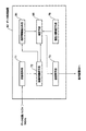
まず、本実施の形態1にかかるX線CT装置の全体構成について説明する。図1は、X線CT装置のブロック(block)図を示す。図1に示すように、本装置は、走査ガントリ(gantry)10,操作コンソール(console)6および撮影テーブル(table)4を有する。
The best mode for carrying out a scattered radiation correction method and an X-ray CT apparatus according to the present invention will be described below with reference to the accompanying drawings. Note that the present invention is not limited thereby.
(Embodiment 1)
First, the overall configuration of the X-ray CT apparatus according to the first embodiment will be described. FIG. 1 shows a block diagram of an X-ray CT apparatus. As shown in FIG. 1, the apparatus includes a scanning gantry 10, an operation console 6, and an imaging table 4.
走査ガントリ10は、X線管20を有する。X線発生装置であるX線管20から放射された図示しないX線は、コリメータ(collimator)22により、例えば、厚みを持って扇状に拡がるコーン状のX線ビーム(beam)となるように成形され、X線管20と対向して配置されたX線検出器24に照射される。
The scanning gantry 10 has an
X線検出器24は、ファンビームX線の広がり方向にマトリックス(matrix)状に配列された複数のシンチレータを有する。X線検出器24は、複数のシンチレータをマトリックス状に配列した、幅のある多チャネルの検出器となっている。
The
X線検出器24は、全体として、凹面状に湾曲したX線入射面を形成する。X線検出器24は、例えば無機結晶からなるシンチレータと光電変換器であるフォトダイオード(photo diode)を組み合わせたものである。
The
X線検出器24には、データ(data)収集部26が接続されている。データ収集部26は、X線検出器24の個々のシンチレータの検出情報を収集する。X線管20からのX線の照射は、X線コントローラ(controller)28によって制御される。なお、X線管20とX線コントローラ28との接続関係およびコリメータ22とコリメータコントローラ30との接続関係については図示を省略する。コリメータ22は、コリメータコントローラ30によって制御される。
A
以上の、X線管20からコリメータコントローラ30までのものが、走査ガントリ10の回転部34に搭載されている。ここで、被検体あるいはファントム(phantom)は、回転部34の中心に位置するボア(bore)29内の撮影テーブル4上に載置される。回転部34は、回転コントローラ36により制御されつつ回転し、X線管20からX線を爆射し、X線検出器24において被検体およびファントムの透過X線を、回転角度に応じたビュー(view)番号(以後、jで現す)および回転方向のX線検出器列のチャネル番号(以後、iで現す)ごとの投影情報として検出する。なお、回転部34と回転コントローラ36との接続関係については図示を省略する。
The above-described components from the
操作コンソール6は、データ処理装置60を有する。データ処理装置60は、例えばコンピュータ(computer)等によって構成される。データ処理装置60には、制御インタフェース(interface)62が接続されている。制御インタフェース62には、走査ガントリ10が接続されている。データ処理装置60は、制御インタフェース62を通じて走査ガントリ10を制御する。
The operation console 6 includes a
走査ガントリ10内のデータ収集部26、X線コントローラ28、コリメータコントローラ30および回転コントローラ36は、制御インタフェース62を通じて制御される。なお、これら各部と制御インタフェース62との個別の接続については図示を省略する。
The
また、データ処理装置60には、データ収集バッファ(buffer)64が接続されている。データ収集バッファ64には、走査ガントリ10のデータ収集部26が接続されている。データ収集部26で収集されたデータがデータ収集バッファ64を通じてデータ処理装置60に入力される。
In addition, a
データ処理装置60は、データ収集バッファ64を通じて収集した透過X線信号すなわち投影情報を用いて画像再構成を行う。また、データ処理装置60には、記憶装置66が接続されている。記憶装置66は、データ収集バッファ64に収集された投影情報や再構成された断層画像情報および本装置の機能を実現するためのプログラム(program)等を記憶する。
The
また、データ処理装置60には、表示装置68と操作装置70がそれぞれ接続されている。表示装置68は、データ処理装置60から出力される断層画像情報やその他の情報を表示する。操作装置70は、オペレータによって操作され、各種の指示や情報等をデータ処理装置60に入力する。オペレータは表示装置68および操作装置70を使用してインタラクティブ(interactive)に本装置を操作する。なお、走査ガントリ10、撮影テーブル4および操作コンソール6は、被検体あるいはファントムを撮影して断層画像を取得する。
Further, a
図2は、データ処理装置60の機能的な構成を示す機能ブロック図である。データ処理装置60は、前処理手段71、画像再構成手段72、後処理手段73、境界情報抽出手段74、補正手段75および散乱X線補正手段76を含む。尚、データ処理装置60は、本発明の画像生成装置の一例である。
FIG. 2 is a functional block diagram showing a functional configuration of the
前処理手段71は、データ収集バッファ64から入力された投影情報に対して、オフセット(offset)補正、X線検出器感度補正等の補正を行う。
The preprocessing
画像再構成手段72は、前処理された投影情報P(i,j)を用いて画像再構成を行い、断層画像情報を生成する。この画像再構成は、投影情報がアキシャルスキャン(axial scan)あるいはヘリカルスキャン(helical scan)を用いて取得された場合にはFBR(Filtered Back Projection)法等が用いられ,また厚みを有する投影情報をボリュームデータ(volume data)として扱い3次元画像再構成法を用いることもできる。
The
後処理手段73は、断層画像情報にCT値変換等の後処理を行う。そして、後処理が行われた断層画像情報は、表示装置68に送信される。
The post-processing means 73 performs post-processing such as CT value conversion on the tomographic image information. The post-processed tomographic image information is transmitted to the
境界情報抽出手段74は、前処理された投影情報P(i,j)からX線吸収率が不連
続的に異なる境界位置の境界位置情報およびこの境界位置におけるX線線吸収率の変化の大きさを示す大きさ情報からなる境界情報を求める。ここで、境界情報抽出手段74は、X線検出器のチャネル方向に対応する方向(以下、単にチャネル方向と呼ぶ)に投影情報を微分する微分演算手段を有し、この微分値が閾値を越える場合に、境界位置と判定する。ここで、ビュー番号j、チャネル番号iの位置のおける投影値をP(i、j)とすると微分値D(i、j)の大きさは、
│D(i、j)│=│[P(i+Δi、j)−P(i、j)]/Δi│
で求まり,閾値をthとして、
│D(i、j)│>th
となるチャネル番号の位置を境界位置とする。
The boundary
| D (i, j) | = | [P (i + Δi, j) −P (i, j)] / Δi |
And the threshold is th,
│D (i, j) │> th
The position of the channel number becomes the boundary position.
散乱X線補正手段76は、投影情報に含まれるビュー番号およびチャネル番号ごとの散乱X線量S(i,j)を算出する。この散乱X線量S(i,j)は、例えばファントム等を用いて取得される散乱X線情報に基づいて算出され、さらにX線が透過する被検体中の投影長をも考慮して精度の高いものとされる(例えば、特許文献1参照)。 The scattered X-ray correction means 76 calculates the scattered X-ray dose S (i, j) for each view number and channel number included in the projection information. This scattered X-ray dose S (i, j) is calculated based on scattered X-ray information acquired by using, for example, a phantom, and further, taking into account the projection length in the subject through which X-rays pass, It is considered high (see, for example, Patent Document 1).
補正手段75は、境界情報抽出手段74で取得される境界情報を用いて、散乱X線補正手段76で算出される散乱X線量に、X線線吸収率が変化する境界位置での補正を加える。ここで、補正手段75は、散乱X線量に乗算され、散乱X線量を補正するゲイン(gain)関数G(i、j)を有する。ここで、ゲイン関数をG(i、j)とすると、例えばfを多次関数として、
G(i、j)=1+f[│D(i、j)│]
で表される。そして、チャネル番号ごとの散乱X線量S(i、j)にゲイン関数G(i、j)が乗算され、境界位置での補正を含んだ散乱X線量とされる。このゲイン関数は、変化の大きさとそれに対する補正量を調整する。なお、この多次関数は、実験的に補正量が最適になるように決定される。
The correcting means 75 uses the boundary information acquired by the boundary
G (i, j) = 1 + f [| D (i, j) |]
It is represented by Then, the scattered X-ray dose S (i, j) for each channel number is multiplied by the gain function G (i, j) to obtain a scattered X-ray dose including correction at the boundary position. This gain function adjusts the magnitude of change and the amount of correction for it. This multi-order function is experimentally determined so that the correction amount is optimized.
また、補正手段75は、この補正された散乱X線量を投影情報から減算し、散乱X線の補正を行う。すなわち、補正後の投影値をCP(i、j)とすると、
CP(i、j)=P(i、j)−S(i、j)*G(i、j)
とされる。そして、補正された投影情報CP(i、j)は、画像再構成手段72に出力され画像再構成される。
Further, the correction means 75 subtracts the corrected scattered X-ray dose from the projection information to correct the scattered X-rays. That is, when the corrected projection value is CP (i, j),
CP (i, j) = P (i, j) -S (i, j) * G (i, j)
It is said. Then, the corrected projection information CP (i, j) is output to the
つぎに、データ処理装置60の補正の具体的な動作について図3を用いて説明する。図3は、補正の動作を示すフローチャートである。まず、オペレータ(operator)は、被検体1をボア29内に配置し、被検体1の投影情報を取得する(ステップS301)。図4(A)は、被検体1の撮影断面を模式的に示した図である。図4(A)に示す例では、被検体1は、概ね楕円形状の低X線吸収率部2と、この楕円形状の中心近傍に位置する円形形状の高X線吸収率部3とを含む断面を有する。図4(B)は、図4(A)に示す被検体1の断面を、面内の上下方向に投影した投影情報を示す図である。この投影情報は、チャネル方向に概ね半円形の低X線吸収率部2の投影像を有し、また半円の中心位置近傍には、高X線吸収率部3を含む小さな半円形の投影像が重畳されている。なお、この様な投影情報が、被検体1の周囲360度に渡って、回転部34の回転角度に応じた各ビュー番号(j)ごとに取得される。
Next, a specific operation of correction of the
その後、境界情報抽出手段74は、投影情報に微分を行い境界情報である境界位置およびX線吸収率の変化の大きさを抽出する(ステップS302)。図4(C)は、図4(B)に示す投影情報に微分演算を行い微分値の大きさを求めた例である。投影情報の投影値が急峻に変化する境界位置では、大きな値を有している。
After that, the boundary
その後、補正手段75は、散乱X線補正手段76で算出されたビュー番号およびチャネル番号ごとの散乱X線量S(i,j)に補正を行う(ステップS303)。この際、補正手段75は、ゲイン関数を用いて微分値、すなわちX線吸収率の変化の大きさと散乱X線量に乗算される補正量を調整する。
Thereafter, the correcting
図5(A)は、図4(A)に示す様な断面を被検体1が有する場合に、散乱X線補正手段76で算出される図4(B)と同様のビュー番号jの投影方向における散乱X線量S(i、j)を示す図である。散乱X線量は、高X線吸収率部3が存在し、投影長が長い中央近傍位置では大きな値となり、投影長が短い周辺位置では徐々に小さなものとなる。図5(B)は、図4(C)に示すチャネル方向位置での微分値の大きさ│D(i、j)│、すなわちX線吸収率の変化の大きさを用いて、散乱X線量S(i、j)を補正した例である。
FIG. 5A shows the projection direction of the view number j similar to FIG. 4B calculated by the scattered X-ray correction means 76 when the
その後、補正手段75は、補正された散乱X線量を用いて投影情報に散乱補正を行う(ステップS304)。この散乱補正では、投影情報の投影値P(i、j)から散乱X線量が減算される。図5(C)は、図5(B)に示す補正された散乱X線量S(i,j)×G(i,j)を用いて図4(B)の投影情報を散乱補正した例である。図5(C)中に実線で示した図は、散乱補正された投影情報CP(i,j)である。なお、図5(C)中に破線で示した図は、図4(B)と同一の投影情報P(i,j)で比較のために図示した。
Thereafter, the correcting
その後、画像再構成手段72は、この補正された投影情報を用いて画像再構成を行い(ステップS305)、再構成された断層画像情報は、表示装置68に表示される(ステップS306)。
Thereafter, the
上述してきたように、本実施の形態1では、被検体1の投影情報P(i,j)から、X線吸収率が変化する境界位置およびこの変化の大きさからなる境界情報D(i,j)を抽出し、この境界情報を用いて、境界位置における変化の大きさに対応する量G(i,j)を散乱X線量S(i,j)に乗算し、境界位置におけるX線を補正することとしているので、断層画像に生じるアーチファクトを減じることができる。
(実施の形態2)
上記実施の形態1では、チャネル方向の投影情報を微分することによって、X線吸収率が変化する境界情報を抽出したが、本実施の形態においては、X線検出器の回転方向と直交する方向の幅であるX線検出器の列方向に対応する方向(以下、単に列方向と呼ぶ)の投影情報を微分することによって、列方向における境界情報を抽出する例について説明する。尚、本実施の形態においては、境界情報抽出手段74及び補正手段75を主に説明し、実施の形態1と同じで構成については説明を省略する。
As described above, in the first embodiment, from the projection information P (i, j) of the subject 1, boundary information D (i, j, which includes the boundary position where the X-ray absorption rate changes and the magnitude of the change. j) is extracted, and using this boundary information, the scattered X-ray dose S (i, j) is multiplied by the amount G (i, j) corresponding to the magnitude of the change at the boundary position, and the X-ray at the boundary position is obtained. Since correction is performed, artifacts generated in the tomographic image can be reduced.
(Embodiment 2)
In the first embodiment, the boundary information in which the X-ray absorption rate changes is extracted by differentiating the projection information in the channel direction. However, in the present embodiment, the direction orthogonal to the rotation direction of the X-ray detector. An example in which boundary information in the column direction is extracted by differentiating projection information in a direction corresponding to the column direction of the X-ray detector (hereinafter simply referred to as the column direction) that is the width of the X-ray detector will be described. In the present embodiment, the boundary
本実施の形態においては、境界情報抽出手段74は、投影情報を列方向に微分する微分演算手段を有し、この微分値が閾値を越える場合に、境界位置と判定する。ここで、ビュー番号j、列番号kの位置における投影値をP(i、k、j)とすると微分値Dk(i、k、j)の大きさは、
|Dk(i、k、j)|=|[P(i、k+Δk、j)−P(i、k、j)] / Δk|
で求まり、閾値をth_kとして、
|Dk(i、k、j)|>th_k
となる列番号の位置を境界位置とする。
In the present embodiment, the boundary
| Dk (i, k, j) | = | [P (i, k + Δk, j) −P (i, k, j)] / Δk |
And the threshold is th_k,
| Dk (i, k, j) |> th_k
The position of the column number that becomes is the boundary position.
散乱X線補正手段76は、投影情報に含まれるビュー番号およびチャンネル番号および列番号ごとの散乱X線量S(i、k、j)を算出する。この散乱X線量S(i、k、j)は、実施の形態1と同様に、例えばファントム等を用いて取得される散乱X線情報に基づいて算出され、さらにX線が透過する被検体中の投影長や投影面積をも考慮して精度のたかいのもとされる。 The scattered X-ray correction means 76 calculates the scattered X-ray dose S (i, k, j) for each view number, channel number, and column number included in the projection information. This scattered X-ray dose S (i, k, j) is calculated based on scattered X-ray information acquired using, for example, a phantom, for example, in the subject through which X-rays pass, as in the first embodiment. Considering the projected length and projected area, the accuracy is raised.
補正手段75は、境界情報抽出手段74で取得される境界情報を用いて、散乱X線補正手段76で算出される散乱X線量に、X線吸収率が変化する境界位置での補正を加える。ここで、補正手段75は、散乱X線量に乗算され、散乱X線量を補正するゲイン(gain)関数G2(i、k、j)を有する。ここで、ゲイン関数をG2(i、k、j)とすると、例えばf2を多次関数として、
G2(i、k、j)=1+f2[|Dk(i、k、j)|]
で表される。そして、散乱X線量S(i、k、j)にゲイン関数G2(i、k、j)が乗算され、境界位置でのX線の補正を含んだ散乱X線量とされる。このゲイン関数は、変化の大きさとそれに対する補正量を調整する。なお、この多次関数は、実験的に補正量が最適になるように決定される。
The
G2 (i, k, j) = 1 + f2 [| Dk (i, k, j) |]
It is represented by Then, the scattered X-ray dose S (i, k, j) is multiplied by the gain function G2 (i, k, j) to obtain a scattered X-ray dose including X-ray correction at the boundary position. This gain function adjusts the magnitude of change and the amount of correction for it. This multi-order function is experimentally determined so that the correction amount is optimized.
また、補正手段75は、この補正された散乱X線量を投影情報から減算し、散乱X線の補正を行う。すなわち、補正後の投影値をCP(i、k、j)とすると、
CP (i、k、j)=P(i、k、j)― S(i、k、j)*G2(i、k、j)
とされる。そして、補正された投影情報CP(i、k、j)は、画像再構成手段72に出力され画像再構成される。
Further, the correcting
CP (i, k, j) = P (i, k, j) −S (i, k, j) * G2 (i, k, j)
It is said. Then, the corrected projection information CP (i, k, j) is output to the
このように、本実施の形態2では、被検体1の投影情報P(i、k、j)から、X線吸収率が変化する境界位置およびこの変化の大きさからなる境界情報D(i、k、j)を抽出し、この境界情報を用いて、境界位置における変化の大きさに対応する量G2(i、k、j)を散乱X線量S(i、k、j)に乗算し、境界位置におけるX線を補正することとしているので、断層画像に生じるアーチファクトを減じることができる。
(実施の形態3)
上記実施の形態1では、チャネル方向の投影情報を、実施の形態2では、列方向の投影情報を微分することによって、X線吸収率が変化する境界情報を抽出したが、本実施の形態においては、チャネル方向と列方向の両方を微分することによって、チャネル方向及び列方向における境界情報を抽出する例について説明する。尚、本実施の形態においては、境界情報抽出手段74及び補正手段75を主に説明し、実施の形態1と同じで構成については説明を省略する。
Thus, in the second embodiment, from the projection information P (i, k, j) of the subject 1, the boundary information D (i, k, j) is extracted, and the boundary information is used to multiply the scattered X-ray dose S (i, k, j) by the amount G2 (i, k, j) corresponding to the magnitude of the change at the boundary position, Since X-rays at the boundary position are corrected, artifacts generated in the tomographic image can be reduced.
(Embodiment 3)
In the first embodiment, the boundary direction information is extracted by differentiating the projection information in the channel direction and in the second embodiment by differentiating the projection information in the column direction. Describes an example of extracting boundary information in the channel direction and the column direction by differentiating both the channel direction and the column direction. In the present embodiment, the boundary
本実施の形態においては、境界情報抽出手段74は、投影情報をチャンネル方向および列方向に微分する微分演算手段を有し、この微分値が閾値を越える場合に、境界位置と判定する。ここで、ビュー番号j、列番号kの位置における投影値をP(i、k、j)とするとチャンネル方向の微分値Di(i、k、j)および列方向の微分値Dk(i、k、j)の大きさは、
|Di(i、k、j)|=|[P(i+Δi、k、j)−P(i、k、j)] / Δi|
|Dk(i、k、j)|=|[P(i、k+Δk、j)−P(i、k、j)] / Δk|
で求まる。チャンネル方向の閾値をth_i、列方向の閾値をth_kとして、
|Di(i、k、j)|>th_i
|Dk(i、k、j)|>th_k
となる列番号の位置を境界位置とする。
In the present embodiment, the boundary
| Di (i, k, j) | = | [P (i + Δi, k, j) −P (i, k, j)] / Δi |
| Dk (i, k, j) | = | [P (i, k + Δk, j) −P (i, k, j)] / Δk |
It is obtained by. Assuming that the threshold in the channel direction is th_i and the threshold in the column direction is th_k,
| Di (i, k, j) |> th_i
| Dk (i, k, j) |> th_k
The position of the column number that becomes is the boundary position.
散乱X線補正手段76は、投影情報に含まれるビュー番号およびチャンネル番号および列番号ごとの散乱X線量S(i、k、j)を算出する。この散乱X線量S(i、k、j)は、実施の形態1と同様に、例えばファントム等を用いて取得される散乱X線情報に基づいて算出され、さらにX線が透過する被検体中の投影長や投影面積をも考慮して精度のたかいのもとされる。 The scattered X-ray correction means 76 calculates the scattered X-ray dose S (i, k, j) for each view number, channel number, and column number included in the projection information. This scattered X-ray dose S (i, k, j) is calculated based on scattered X-ray information acquired using, for example, a phantom or the like, as in the first embodiment, and further in the subject through which X-rays pass. Considering the projected length and projected area, the accuracy is raised.
補正手段75は、境界情報抽出手段74で取得される境界情報を用いて、散乱X線補正手段76で算出される散乱X線量に、X線吸収率が変化する境界位置での補正を加える。ここで、補正手段75は、散乱X線量に乗算され、散乱X線量を補正するゲイン(gain)関数G3(i、k、j)を有する。ここで、ゲイン関数をG3(i、k、j)とすると、例えばf3を多次関数として、
G3(i、k、j)=1+f3[|Di(i、k、j)|、|Dk(i、k、j)|]
で表される。そして、散乱X線量S(i、k、j)にゲイン関数G3(i、k、j)が乗算され、境界位置での補正を含んだ散乱X線量とされる。このゲイン関数は、変化の大きさとそれに対する補正量を調整する。なお、この多次関数は、実験的に補正量が最適になるように決定される。
The
G3 (i, k, j) = 1 + f3 [| Di (i, k, j) |, | Dk (i, k, j) |]
It is represented by Then, the scattered X-ray dose S (i, k, j) is multiplied by the gain function G3 (i, k, j) to obtain a scattered X-ray dose including correction at the boundary position. This gain function adjusts the magnitude of change and the amount of correction for it. This multi-order function is experimentally determined so that the correction amount is optimized.
また、補正手段75は、この補正された散乱X線量を投影情報から減算し、散乱X線の補正を行う。すなわち、補正後の投影値をCP(i、k、j)とすると、
CP (i、k、j)=P(i、k、j)― S(i、k、j)*G3(i、k、j)
とされる。そして、補正された投影情報CP(i、k、j)は、画像再構成手段72に出力され画像再構成される。
Further, the correction means 75 subtracts the corrected scattered X-ray dose from the projection information to correct the scattered X-rays. That is, if the projection value after correction is CP (i, k, j),
CP (i, k, j) = P (i, k, j) −S (i, k, j) * G3 (i, k, j)
It is said. Then, the corrected projection information CP (i, k, j) is output to the
このように、本実施の形態2では、被検体1の投影情報P(i、k、j)から、X線吸収率が変化する境界位置およびこの変化の大きさからなる境界情報D(i、k、j)を抽出し、この境界情報を用いて、境界位置における変化の大きさに対応する量G2(i、k、j)を散乱X線量S(i、k、j)に乗算し、境界位置におけるX線を補正することとしているので、チャネル方向及び列方向の投影情報の散乱X線補正を補正し、ひいては断層画像に生じるアーチファクトを減じることができる。
(実施の形態4)
ところで、上記実施の形態1〜3では、投影情報P(i,j)を微分し、X線吸収率が変化する境界情報D(i,j)を抽出することとしたが、画像再構成された断層画像情報から境界情報を抽出し、境界位置におけるX線の補正を行うこともできる。そこで、本実施の形態4では、画像再構成された断層画像情報から境界情報を抽出し、X線吸収率が変化する境界位置におけるX線の補正を行う場合を示すことにする。図6は、本実施の形態2にかかるデータ処理装置61の機能的な構成を示す機能ブロック図である。ここで、データ処理装置61は、図1の全体構成に示すデータ処理装置60に対応するもので、その他の構成は図1に示すものと全く同様であるので、詳しい説明を省略する。
Thus, in the second embodiment, from the projection information P (i, k, j) of the subject 1, the boundary information D (i, k, j) is extracted, and the boundary information is used to multiply the scattered X-ray dose S (i, k, j) by the amount G2 (i, k, j) corresponding to the magnitude of the change at the boundary position, Since X-rays at the boundary position are corrected, it is possible to correct the scattered X-ray correction of the projection information in the channel direction and the column direction, thereby reducing artifacts generated in the tomographic image.
(Embodiment 4)
In the first to third embodiments, the projection information P (i, j) is differentiated and the boundary information D (i, j) whose X-ray absorption rate changes is extracted. It is also possible to extract boundary information from the tomographic image information and correct X-rays at the boundary position. Therefore, the fourth embodiment shows a case where boundary information is extracted from tomographic image information reconstructed and X-ray correction is performed at the boundary position where the X-ray absorption rate changes. FIG. 6 is a functional block diagram of a functional configuration of the data processing device 61 according to the second embodiment. Here, the data processing device 61 corresponds to the
データ処理装置61は、前処理手段71、画像再構成手段72、後処理手段73、境界情報抽出手段84、補正手段85および散乱X線補正手段76を含む。ここで、前処理手段71、画像再構成手段72、後処理手段73および散乱X線補正手段76は、図2に示したものと機能的には全く同様である。ただし、実施の形態1では、前処理手段71は、前処理された投影情報を境界情報抽出手段74にのみ出力していたが、本実施の形態2では、画像再構成手段72および補正手段85に出力する。そして、画像再構成手段72は、前処理手段71からの投影情報を用いて画像再構成を行い断層画像情報を形成する。
The data processing device 61 includes pre-processing means 71, image reconstruction means 72, post-processing means 73, boundary information extraction means 84, correction means 85, and scattered X-ray correction means 76. Here, the preprocessing means 71, the image reconstruction means 72, the post-processing means 73, and the scattered X-ray correction means 76 are functionally the same as those shown in FIG. However, in the first embodiment, the preprocessing means 71 outputs the preprocessed projection information only to the boundary information extraction means 74, but in the second embodiment, the image reconstruction means 72 and the correction means 85. Output to. Then, the
境界情報抽出手段84は、画像再構成手段72から取得した断層画像情報IMG(x,y)(x、yは、画像の横および縦方向の位置座標を示す。)を用いて、X線吸収率が不連続的に異なる境界位置の境界位置情報およびこの境界位置におけるX線吸収率の変化の大きさを示す大きさ情報からなる境界情報を求める。ここで、境界情報抽出手段84は、断層画像情報に含まれる断層画像を微分する微分演算手段、微分された画像の絶対値を取り境界画像を生成する絶対値手段およびこの境界画像を用いて各ビュー角度に対応する位置からの複数の投影像を求める再投影手段を有する。
The boundary
ここで、断層画像IMG(x、y)から境界画像をBIMG(x、y)を生成する際には、 Here, when generating a boundary image BIMG (x, y) from the tomographic image IMG (x, y),

の関係にある式(1)が用いられる。なお、*は、畳み込み演算を現し、HF(x、y)は、高域通過型のフィルタ(filter)関数である。この式の分子は上述した微分演算手段をなし、分母はCT値に依存させないための規格化因子である。 Equation (1) in the relationship is used. Note that * represents a convolution operation, and HF (x, y) is a high-pass filter function. The numerator of this formula is the above-described differential calculation means, and the denominator is a normalization factor for not depending on the CT value.
そして、境界情報抽出手段84は、この境界画像BIMG(x,y)の投影像BD(i,j)をビュー番号およびチャネル番号ごとに求める。そして、境界情報抽出手段84は、投影像BD(i,j)が零でない投影値を有する際に、この投影値が存在するチャネル方向の位置を境界位置とし、投影値の大きさをX線吸収率の変化の大きさとする。
Then, the boundary
補正手段85は、境界情報抽出手段84で取得される境界情報を用いて、散乱X線補正手段76で算出される散乱X線量に、X線吸収率が変化する境界位置でのX線の補正を加える。ここで、補正手段85は、補正手段75と同様の散乱X線量に乗算され、散乱X線量を補正するゲイン関数を有する。このゲイン関数は、例えば、fを多次関数として、
G(i、j)=1+f[│BD(i、j)│]
で表される。また、散乱X線量をS(i、j)とすると、定義からS(i、j)×G(i、j)が補正された散乱X線量となる。
The
G (i, j) = 1 + f [| BD (i, j) |]
It is represented by When the scattered X-ray dose is S (i, j), the scattered X-ray dose is corrected by S (i, j) × G (i, j) from the definition.
また、補正手段85は、この補正された散乱X線量CP(i,j)を前処理手段71からの投影情報P(i、j)から減算し、散乱X線の補正を行う。
CP(i、j)=P(i、j)−S(i、j)×G(i、j)
つぎに、データ処理装置61の補正の具体的な動作について図7を用いて説明する。図7は、補正の動作を示すフローチャートである。まず、オペレータ(operator)は、被検体2をボア29内に配置し、被検体2の投影情報を取得する(ステップS701)。この投影情報は、データ処理装置61に送信され、前処理手段71で前処理された後に画像再構成手段72に出力される。そして、画像再構成手段72は、この投影情報P(i,j)を画像再構成し(ステップS702)、断層画像情報IMG(x,y)を取得する。図8(A)は、被検体2の断層画像の一例である。この断層画像は、被検体2の大部分を占める低X線吸収率部8と、この低X線吸収率部8の中にある2つの円形の高X線吸収率部9とからなる。なお、この断層画像中に破線で示す部分は、X線吸収率が変化する境界位置でのアーチファクト7を模式的に示すものである。
Further, the correcting
CP (i, j) = P (i, j) −S (i, j) × G (i, j)
Next, a specific operation of correction of the data processing device 61 will be described with reference to FIG. FIG. 7 is a flowchart showing the correction operation. First, an operator places the subject 2 in the bore 29 and acquires projection information of the subject 2 (step S701). This projection information is transmitted to the data processing device 61, pre-processed by the
図7に戻り、データ処理装置61は、境界情報抽出手段84により、境界情報の抽出を行う(ステップS703)。この境界情報の抽出では、断層画像IMG(x,y)に(1)式を用いた演算を行い境界画像BIMG(x,y)を求める。図8(B)は、図8(A)に示す断層画像から求めた境界画像を示す図である。この図では、被検体2の低X線線吸収率部8および高X線吸収率部9の境界領域のみが抽出されている。そして、境界情報抽出手段84は、この境界画像BIMG(x,y)から、ビュー番号およびチャネル番号ごとの境界情報である境界投影値BD(i,j)を算出する。図8(C)は、図8(B)に示す境界画像の面内で上下方向に投影した境界投影値の例である。図8(C)では、境界投影値が、低X線吸収率部8の辺縁部および高X線吸収率部9の辺縁部では大きなものとなっており、また高X線吸収率部9を含む境界投影値は、低X線吸収率部8のみからなる境界投影値よりも大きな値を示している。
Returning to FIG. 7, the data processing device 61 extracts boundary information by the boundary information extracting means 84 (step S703). In this boundary information extraction, a calculation using the equation (1) is performed on the tomographic image IMG (x, y) to obtain the boundary image BIMG (x, y). FIG. 8B is a diagram showing a boundary image obtained from the tomographic image shown in FIG. In this figure, only the boundary region between the low X-ray absorption rate portion 8 and the high X-ray absorption rate portion 9 of the subject 2 is extracted. Then, the boundary
図7に戻り、その後データ処理装置61は、補正手段85により、散乱X線量を補正する(ステップS704)。この補正では、境界投影値BD(i,j)を用いたゲイン関数G(i、j)を求め、このゲイン関数G(i、j)を散乱X線量S(i、j)に乗算する。 Returning to FIG. 7, the data processing device 61 then corrects the scattered X-ray dose by the correcting means 85 (step S704). In this correction, a gain function G (i, j) using the boundary projection value BD (i, j) is obtained, and the scattered X-ray dose S (i, j) is multiplied by this gain function G (i, j).
図9(A)は、散乱X線補正手段76で求められた被検体2の上下方向の散乱X線量S(i、j)を示す図である。図9(B)は、この散乱X線量S(i、j)に、境界投影値BD(i,j)のゲイン関数G(i、j)を乗算して補正した散乱X線量を示す図である。 FIG. 9A is a diagram showing the scattered X-ray dose S (i, j) in the vertical direction of the subject 2 obtained by the scattered X-ray correction means 76. FIG. 9B shows the scattered X-ray dose corrected by multiplying the scattered X-ray dose S (i, j) by the gain function G (i, j) of the boundary projection value BD (i, j). is there.
図7に戻り、データ処理装置61は、補正手段85により、散乱補正を行う(ステップS705)。この散乱補正では、補正手段85は、前処理手段71から取得した被検体2の投影情報P(i,j)から、補正された散乱X線量S(i、j)×G(i、j)を減算する。図9(C)は、図中の破線で被検体2の投影情報P(i,j)を示し、図中の実線で散乱補正が行われた被検体2の投影情報CP(i、j)を示している。 Returning to FIG. 7, the data processing device 61 performs scattering correction by the correcting means 85 (step S705). In this scatter correction, the correction means 85 corrects the scattered X-ray dose S (i, j) × G (i, j) from the projection information P (i, j) of the subject 2 acquired from the preprocessing means 71. Is subtracted. FIG. 9C shows the projection information P (i, j) of the subject 2 with a broken line in the drawing, and the projection information CP (i, j) of the subject 2 subjected to scattering correction with the solid line in the drawing. Is shown.
図7に戻り、データ処理装置61は、画像再構成手段72により、散乱補正を行った投影情報CP(i、j)を画像再構成し(ステップS706)、この再構成画像を表示装置68に表示する(ステップS707)。なお、この再構成画像では、図8(A)の断層画像に示されたアーチファクト7の低減が図られる。
Returning to FIG. 7, the data processing device 61 uses the
上述してきたように、本実施の形態2では、被検体2の断層画像IMG(x,y)から、X線吸収率が変化する境界位置のみからなる境界画像BIMG(x,y)を抽出し、この境界画像の境界投影値BD(i,j)をビュー番号およびチャネル番号ごとに算出し、この境界投影値を用いて散乱X線量S(i,j)を補正し、この散乱X線量を用いて被検体2の投影情報P(i,j)の散乱補正を行うこととしているので、X線吸収率が異なる境界位置におけるX線の散乱補正を補正し、ひいては断層画像に生じるアーチファクト7を減じることができる。
(実施の形態5)
ところで、上記実施の形態4では、断層画像から境界画像BIMG(x,y)を抽出し、この境界画像の境界投影値BD(i,j)を用いて被検体2の投影情報を補正したが、境界投影値に基づいて補正された散乱X線量を画像再構成して散乱X線画像を生成し、この散乱X線画像を断層画像から減算して散乱線X線およびアーチファクトの軽減を図ることもできる。そこで、本実施の形態5では、境界投影値で補正された散乱X線画像を用いて、断層画像のX線吸収率が変化する境界位置におけるX線を補正する場合を示すことにする。図10は、本実施の形態5にかかるデータ処理装置63の機能的な構成を示す機能ブロック図である。ここで、データ処理装置63は、図1の全体構成に示すデータ処理装置60に対応するもので、その他の構成は図1に示すものと全く同様であるので、詳しい説明を省略する。
As described above, in the second embodiment, the boundary image BIMG (x, y) consisting only of the boundary position where the X-ray absorption rate changes is extracted from the tomographic image IMG (x, y) of the
(Embodiment 5)
In the fourth embodiment, the boundary image BIMG (x, y) is extracted from the tomographic image, and the projection information of the subject 2 is corrected using the boundary projection value BD (i, j) of the boundary image. Then, the scattered X-ray dose corrected based on the boundary projection value is reconstructed to generate a scattered X-ray image, and the scattered X-ray image is subtracted from the tomographic image to reduce scattered X-rays and artifacts. You can also. Therefore, the fifth embodiment shows a case where X-rays at the boundary position where the X-ray absorption rate of the tomographic image changes are corrected using the scattered X-ray image corrected with the boundary projection value. FIG. 10 is a functional block diagram of a functional configuration of the data processing device 63 according to the fifth embodiment. Here, the data processing device 63 corresponds to the
データ処理装置63は、前処理手段71、画像再構成手段72、後処理手段73、境界情報抽出手段84、補正手段95および散乱X線補正手段76を含む。ここで、前処理手段71、画像再構成手段72、後処理手段73、境界情報抽出手段84および散乱X線補正手段76は、図6に示した実施の形態2のものと機能的には全く同様であるので詳しい説明を省略する。ただし、本実施の形態3では、前処理手段71は、前処理された投影情報を補正手段95に出力せず、補正手段95は、画像再構成された断層画像および散乱X線画像のみを用いて境界位置のX線を補正する。また、画像再構成手段72は、後処理手段73に直接再構成画像を出力せず、補正手段95を介して出力する。
The data processing device 63 includes preprocessing means 71, image reconstruction means 72, postprocessing means 73, boundary information extraction means 84, correction means 95, and scattered X-ray correction means 76. Here, the pre-processing means 71, the image reconstruction means 72, the post-processing means 73, the boundary information extraction means 84, and the scattered X-ray correction means 76 are functionally completely different from those of the second embodiment shown in FIG. Since it is the same, detailed description is abbreviate | omitted. However, in the third embodiment, the preprocessing
図11(A)は、被検体2の投影情報から画像再構成される断層画像IMG(x、y)の例である。被検体2は、低X線吸収率部8とその中に2つの円形の高X線吸収率部9を有する。そして、低X線吸収率部8および高X線吸収率部9の辺縁部には、アーチファクト7が破線で示されている。
FIG. 11A is an example of a tomographic image IMG (x, y) reconstructed from the projection information of the
補正手段95は、補正手段85と同様に境界情報抽出手段84により境界画像BIMG(x.y)から取得される境界投影値BD(i,j)を用いて、散乱X線補正手段76で算出される散乱X線量S(i、j)を補正する。なお、断層画像IMG(x、y)から境界画像をBIMG(x、y)を生成する際には、 The correction means 95 is calculated by the scattered X-ray correction means 76 using the boundary projection value BD (i, j) acquired from the boundary image BIMG (xy) by the boundary information extraction means 84 as in the correction means 85. The scattered X-ray dose S (i, j) to be corrected is corrected. When generating a boundary image BIMG (x, y) from the tomographic image IMG (x, y),
の関係にある式(2)が用いられる。なお、*は、畳み込み演算を現し、HF(x、y)は、高域通過型のフィルタ(filter)関数である。また、補正手段85と同様にゲイン関数G(i、j)を用いて、境界投影値BD(i,j)を変換する。
Equation (2) in the relationship is used. Note that * represents a convolution operation, and HF (x, y) is a high-pass filter function. Similarly to the
その後、補正手段95は、補正された散乱X線量S(i、j)×G(i、j)を画像再構成手段72に出力する。画像再構成手段72は、補正された散乱X線量を画像再構成し散乱X線画像SIMG(x、y)を生成する。図11(B)は、画像再構成された散乱X線画像を模式的に示す図である。概ね、図11(A)に示すアーチファクト7部分を画像化したものとなる。
Thereafter, the
その後、補正手段95は、画像再構成手段72からこの散乱X線画像SIMG(x,y)を入力し、断層画像IMG(x,y)との減算を行い減算画像DIMG(x、y)を生成する。すなわち、
DIMG(x,y)=IMG(x、y)−SIMG(x、y)
を算出する。図11(C)は、減算された減算画像を示している。減算画像は、概ね断層画像からアーチファクト7部分を取り除いたものとなっている。
Thereafter, the
DIMG (x, y) = IMG (x, y) −SIMG (x, y)
Is calculated. FIG. 11C shows a subtracted image obtained by subtraction. The subtracted image is generally obtained by removing the
その後、補正手段95は、後処理手段73に減算画像を出力し、また後処理手段73は、後処理の後に表示装置68にこの減算画像を出力する。
Thereafter, the correction means 95 outputs the subtraction image to the post-processing means 73, and the post-processing means 73 outputs the subtraction image to the
上述してきたように、本実施の形態3では、被検体2の断層画像IMG(x,y)の境界のみからなる境界画像BIMG(x,y)から境界投影値BP(i,j)をビュー番号およびチャネル番号ごとに算出し、この境界投影値を用いて散乱X線量S(i,j)を補正し、この散乱X線量を画像再構成して散乱X線画像SIMG(x,y)を生成し、断層画像から減算することとしているので、断層画像に生じるアーチファクト7を減じることができる。
As described above, in the third embodiment, the boundary projection value BP (i, j) is viewed from the boundary image BIMG (x, y) including only the boundary of the tomographic image IMG (x, y) of the
1、2 被検体
2、8 低X線吸収率部
3、9高X線吸収率部
7 アーチファクト
4 撮影テーブル
6 操作コンソール
10 走査ガントリ
20 X線管
22 コリメータ
24 X線検出器
26 データ収集部
28 X線コントローラ
29 ボア
30 コリメータコントローラ
34 回転部
36 回転コントローラ
60、61、63 データ処理装置
62 制御インタフェース
64 データ収集バッファ
66 記憶装置
68 表示装置
70 操作装置
71 前処理手段
72 画像再構成手段
73 後処理手段
74 境界情報抽出手段
75 補正手段
76 散乱X線補正手段
84 境界情報抽出手段
85、95 補正手段
1, 2
Claims (12)
前記X線投影データを用いて被検体の画像情報を生成する画像情報生成手段と
を有するX線CT装置において、
前記画像生成手段は、
被検体のX線投影情報または前記投影情報を画像再構成して生成される断層画像情報を用いて、前記被検体内部の境界位置を含むX線吸収率が変化する境界位置の境界位置情報および前記変化の大きさを示す大きさ情報を含む境界情報を抽出する手段と、
前記被検体を通過するX線の透過長及び前記境界情報を含む情報に基づいて求められた前記投影情報または前記断層画像情報における散乱X線補正量を、前記投影情報または前記断層画像情報から減算して補正する補正手段と
を含むことを特徴とするX線CT装置。 An X-ray data collection means for collecting X-ray projection data by relatively rotating an X-ray generator and an X-ray detector disposed so as to face the X-ray generator around the subject;
In an X-ray CT apparatus having image information generating means for generating image information of a subject using the X-ray projection data,
The image generating means includes
Using the X-ray projection information of the subject or tomographic image information generated by image reconstruction of the projection information, boundary position information of the boundary position where the X-ray absorption rate including the boundary position inside the subject changes, and Means for extracting boundary information including size information indicating the magnitude of the change;
The scattered X-ray correction amount in the projection information or the tomographic image information obtained based on the information including the transmission length of the X-ray passing through the subject and the boundary information is subtracted from the projection information or the tomographic image information. And an X-ray CT apparatus including correction means for correcting the X-ray CT.
Priority Applications (1)
| Application Number | Priority Date | Filing Date | Title |
|---|---|---|---|
| JP2012037447A JP5389965B2 (en) | 2005-12-21 | 2012-02-23 | Scattered ray correction method and X-ray CT apparatus |
Applications Claiming Priority (3)
| Application Number | Priority Date | Filing Date | Title |
|---|---|---|---|
| JP2005367389 | 2005-12-21 | ||
| JP2005367389 | 2005-12-21 | ||
| JP2012037447A JP5389965B2 (en) | 2005-12-21 | 2012-02-23 | Scattered ray correction method and X-ray CT apparatus |
Related Parent Applications (1)
| Application Number | Title | Priority Date | Filing Date |
|---|---|---|---|
| JP2006177692A Division JP5010859B2 (en) | 2005-12-21 | 2006-06-28 | Image generation device |
Publications (2)
| Publication Number | Publication Date |
|---|---|
| JP2012096111A JP2012096111A (en) | 2012-05-24 |
| JP5389965B2 true JP5389965B2 (en) | 2014-01-15 |
Family
ID=46388679
Family Applications (1)
| Application Number | Title | Priority Date | Filing Date |
|---|---|---|---|
| JP2012037447A Expired - Fee Related JP5389965B2 (en) | 2005-12-21 | 2012-02-23 | Scattered ray correction method and X-ray CT apparatus |
Country Status (1)
| Country | Link |
|---|---|
| JP (1) | JP5389965B2 (en) |
Cited By (2)
| Publication number | Priority date | Publication date | Assignee | Title |
|---|---|---|---|---|
| US11373308B2 (en) | 2019-02-01 | 2022-06-28 | Samsung Electronics Co., Ltd. | X-ray image processing method and X-ray image processing apparatus |
| US11540785B2 (en) | 2019-01-25 | 2023-01-03 | Samsung Electronics Co., Ltd. | X-ray image processing method and x-ray image processing apparatus |
Family Cites Families (10)
| Publication number | Priority date | Publication date | Assignee | Title |
|---|---|---|---|---|
| JPS635479A (en) * | 1986-06-26 | 1988-01-11 | Toshiba Corp | X-ray picture processor |
| JPH0594515A (en) * | 1991-09-30 | 1993-04-16 | Shimadzu Corp | Digital image processor |
| JP3206217B2 (en) * | 1993-05-31 | 2001-09-10 | 株式会社島津製作所 | Image processing device |
| JP3437226B2 (en) * | 1993-10-20 | 2003-08-18 | キヤノン株式会社 | Image processing method and apparatus |
| JP3426677B2 (en) * | 1994-01-27 | 2003-07-14 | 株式会社日立メディコ | X-ray CT system |
| JP3540914B2 (en) * | 1997-05-19 | 2004-07-07 | 株式会社日立メディコ | X-ray equipment |
| JP3583554B2 (en) * | 1996-07-23 | 2004-11-04 | 株式会社日立メディコ | Cone beam X-ray tomography system |
| JP2001197321A (en) * | 2000-01-12 | 2001-07-19 | Nec Shizuoka Ltd | Color picture processing method and picture processor |
| JP2003102719A (en) * | 2001-09-25 | 2003-04-08 | Ge Medical Systems Global Technology Co Llc | Tomographic image pickup system, and operation console and control method therefor |
| JP4316335B2 (en) * | 2003-09-25 | 2009-08-19 | ジーイー・メディカル・システムズ・グローバル・テクノロジー・カンパニー・エルエルシー | X-ray scattered ray component correction method and program, and X-ray CT apparatus |
-
2012
- 2012-02-23 JP JP2012037447A patent/JP5389965B2/en not_active Expired - Fee Related
Cited By (2)
| Publication number | Priority date | Publication date | Assignee | Title |
|---|---|---|---|---|
| US11540785B2 (en) | 2019-01-25 | 2023-01-03 | Samsung Electronics Co., Ltd. | X-ray image processing method and x-ray image processing apparatus |
| US11373308B2 (en) | 2019-02-01 | 2022-06-28 | Samsung Electronics Co., Ltd. | X-ray image processing method and X-ray image processing apparatus |
Also Published As
| Publication number | Publication date |
|---|---|
| JP2012096111A (en) | 2012-05-24 |
Similar Documents
| Publication | Publication Date | Title |
|---|---|---|
| JP5010859B2 (en) | Image generation device | |
| Mertelmeier et al. | Optimizing filtered backprojection reconstruction for a breast tomosynthesis prototype device | |
| CN103156629B (en) | Image processing equipment and image processing method | |
| US8965078B2 (en) | Projection-space denoising with bilateral filtering in computed tomography | |
| US8401266B2 (en) | Method and system for correlated noise suppression in dual energy imaging | |
| US20130202079A1 (en) | System and Method for Controlling Radiation Dose for Radiological Applications | |
| US7756312B2 (en) | Methods and apparatus for noise estimation | |
| US6493416B1 (en) | Method and apparatus for noise reduction in computed tomographic systems | |
| JP3987024B2 (en) | Method and system for enhancing tomosynthesis images using lateral filtering | |
| US20180047156A1 (en) | Focal spot de-blurring | |
| JP2007021021A (en) | Image processing device and x-ray ct apparatus | |
| EP1975881A2 (en) | Method and system for reconstructing a medical image of an object | |
| JP5389965B2 (en) | Scattered ray correction method and X-ray CT apparatus | |
| EP1677255B1 (en) | Method and arrangement for three-dimensional medical X-ray imaging | |
| EP1677256B1 (en) | Method and arrangement for multiresolutive reconstruction for medical X-ray imaging | |
| Li et al. | X-ray digital intra-oral tomosynthesis for quasi-three-dimensional imaging: system, reconstruction algorithm, and experiments | |
| JP7187131B2 (en) | Image generation device, X-ray computed tomography device and image generation method | |
| US6647084B1 (en) | Method and apparatus for filtering projection data of a helical scan | |
| JP2004357969A (en) | X-ray measuring instrument | |
| JP4703221B2 (en) | X-ray CT system | |
| JP5406430B2 (en) | Image reconstruction system using low noise kernel | |
| JP4414168B2 (en) | Calcification index measuring method and X-ray CT apparatus | |
| JP2024177153A (en) | Apparatus and method for estimating scattered radiation in a computed tomography imaging system, and information processing device | |
| WO2018116791A1 (en) | Medical image processing device and x-ray ct device provided with same, and medical image processing method | |
| Carminati et al. | MuhRec–a reconstruction tool for neutron and x-ray tomography |
Legal Events
| Date | Code | Title | Description |
|---|---|---|---|
| A625 | Written request for application examination (by other person) |
Free format text: JAPANESE INTERMEDIATE CODE: A625 Effective date: 20120227 |
|
| A131 | Notification of reasons for refusal |
Free format text: JAPANESE INTERMEDIATE CODE: A131 Effective date: 20130219 |
|
| A521 | Request for written amendment filed |
Free format text: JAPANESE INTERMEDIATE CODE: A523 Effective date: 20130516 |
|
| A131 | Notification of reasons for refusal |
Free format text: JAPANESE INTERMEDIATE CODE: A131 Effective date: 20130611 |
|
| A521 | Request for written amendment filed |
Free format text: JAPANESE INTERMEDIATE CODE: A523 Effective date: 20130618 |
|
| TRDD | Decision of grant or rejection written | ||
| A01 | Written decision to grant a patent or to grant a registration (utility model) |
Free format text: JAPANESE INTERMEDIATE CODE: A01 Effective date: 20130910 |
|
| A61 | First payment of annual fees (during grant procedure) |
Free format text: JAPANESE INTERMEDIATE CODE: A61 Effective date: 20131009 |
|
| R150 | Certificate of patent or registration of utility model |
Ref document number: 5389965 Country of ref document: JP Free format text: JAPANESE INTERMEDIATE CODE: R150 Free format text: JAPANESE INTERMEDIATE CODE: R150 |
|
| R250 | Receipt of annual fees |
Free format text: JAPANESE INTERMEDIATE CODE: R250 |
|
| R250 | Receipt of annual fees |
Free format text: JAPANESE INTERMEDIATE CODE: R250 |
|
| R250 | Receipt of annual fees |
Free format text: JAPANESE INTERMEDIATE CODE: R250 |
|
| R250 | Receipt of annual fees |
Free format text: JAPANESE INTERMEDIATE CODE: R250 |
|
| LAPS | Cancellation because of no payment of annual fees |