JP5389101B2 - Motor control device - Google Patents
Motor control device Download PDFInfo
- Publication number
- JP5389101B2 JP5389101B2 JP2011097993A JP2011097993A JP5389101B2 JP 5389101 B2 JP5389101 B2 JP 5389101B2 JP 2011097993 A JP2011097993 A JP 2011097993A JP 2011097993 A JP2011097993 A JP 2011097993A JP 5389101 B2 JP5389101 B2 JP 5389101B2
- Authority
- JP
- Japan
- Prior art keywords
- motor
- rotation angle
- calculation
- calculation means
- sub
- Prior art date
- Legal status (The legal status is an assumption and is not a legal conclusion. Google has not performed a legal analysis and makes no representation as to the accuracy of the status listed.)
- Expired - Fee Related
Links
- 238000001514 detection method Methods 0.000 claims description 54
- 230000005284 excitation Effects 0.000 claims description 51
- 238000012544 monitoring process Methods 0.000 claims description 39
- 230000005856 abnormality Effects 0.000 claims description 11
- 230000003321 amplification Effects 0.000 claims description 6
- 238000003199 nucleic acid amplification method Methods 0.000 claims description 6
- 238000000034 method Methods 0.000 description 16
- 230000009467 reduction Effects 0.000 description 12
- 230000002159 abnormal effect Effects 0.000 description 5
- 238000004891 communication Methods 0.000 description 4
- 238000010586 diagram Methods 0.000 description 4
- 230000000694 effects Effects 0.000 description 3
- 230000008859 change Effects 0.000 description 2
- 230000005279 excitation period Effects 0.000 description 2
- 230000007935 neutral effect Effects 0.000 description 2
- 230000000903 blocking effect Effects 0.000 description 1
- 244000145845 chattering Species 0.000 description 1
- 238000006243 chemical reaction Methods 0.000 description 1
- 230000001771 impaired effect Effects 0.000 description 1
- 230000002265 prevention Effects 0.000 description 1
- 230000008569 process Effects 0.000 description 1
- 230000004044 response Effects 0.000 description 1
- 230000000630 rising effect Effects 0.000 description 1
- 230000001360 synchronised effect Effects 0.000 description 1
- 230000007704 transition Effects 0.000 description 1
Images


Classifications
-
- B—PERFORMING OPERATIONS; TRANSPORTING
- B62—LAND VEHICLES FOR TRAVELLING OTHERWISE THAN ON RAILS
- B62D—MOTOR VEHICLES; TRAILERS
- B62D5/00—Power-assisted or power-driven steering
- B62D5/04—Power-assisted or power-driven steering electrical, e.g. using an electric servo-motor connected to, or forming part of, the steering gear
- B62D5/0457—Power-assisted or power-driven steering electrical, e.g. using an electric servo-motor connected to, or forming part of, the steering gear characterised by control features of the drive means as such
- B62D5/046—Controlling the motor
-
- B—PERFORMING OPERATIONS; TRANSPORTING
- B62—LAND VEHICLES FOR TRAVELLING OTHERWISE THAN ON RAILS
- B62D—MOTOR VEHICLES; TRAILERS
- B62D5/00—Power-assisted or power-driven steering
- B62D5/04—Power-assisted or power-driven steering electrical, e.g. using an electric servo-motor connected to, or forming part of, the steering gear
- B62D5/0457—Power-assisted or power-driven steering electrical, e.g. using an electric servo-motor connected to, or forming part of, the steering gear characterised by control features of the drive means as such
- B62D5/0481—Power-assisted or power-driven steering electrical, e.g. using an electric servo-motor connected to, or forming part of, the steering gear characterised by control features of the drive means as such monitoring the steering system, e.g. failures
- B62D5/0484—Power-assisted or power-driven steering electrical, e.g. using an electric servo-motor connected to, or forming part of, the steering gear characterised by control features of the drive means as such monitoring the steering system, e.g. failures for reaction to failures, e.g. limp home
-
- B—PERFORMING OPERATIONS; TRANSPORTING
- B62—LAND VEHICLES FOR TRAVELLING OTHERWISE THAN ON RAILS
- B62D—MOTOR VEHICLES; TRAILERS
- B62D5/00—Power-assisted or power-driven steering
- B62D5/04—Power-assisted or power-driven steering electrical, e.g. using an electric servo-motor connected to, or forming part of, the steering gear
- B62D5/0457—Power-assisted or power-driven steering electrical, e.g. using an electric servo-motor connected to, or forming part of, the steering gear characterised by control features of the drive means as such
- B62D5/0481—Power-assisted or power-driven steering electrical, e.g. using an electric servo-motor connected to, or forming part of, the steering gear characterised by control features of the drive means as such monitoring the steering system, e.g. failures
- B62D5/0487—Power-assisted or power-driven steering electrical, e.g. using an electric servo-motor connected to, or forming part of, the steering gear characterised by control features of the drive means as such monitoring the steering system, e.g. failures detecting motor faults
-
- H—ELECTRICITY
- H02—GENERATION; CONVERSION OR DISTRIBUTION OF ELECTRIC POWER
- H02P—CONTROL OR REGULATION OF ELECTRIC MOTORS, ELECTRIC GENERATORS OR DYNAMO-ELECTRIC CONVERTERS; CONTROLLING TRANSFORMERS, REACTORS OR CHOKE COILS
- H02P27/00—Arrangements or methods for the control of AC motors characterised by the kind of supply voltage
- H02P27/04—Arrangements or methods for the control of AC motors characterised by the kind of supply voltage using variable-frequency supply voltage, e.g. inverter or converter supply voltage
- H02P27/06—Arrangements or methods for the control of AC motors characterised by the kind of supply voltage using variable-frequency supply voltage, e.g. inverter or converter supply voltage using DC to AC converters or inverters
Landscapes
- Engineering & Computer Science (AREA)
- Chemical & Material Sciences (AREA)
- Combustion & Propulsion (AREA)
- Transportation (AREA)
- Mechanical Engineering (AREA)
- Power Engineering (AREA)
- Control Of Motors That Do Not Use Commutators (AREA)
- Steering Control In Accordance With Driving Conditions (AREA)
- Power Steering Mechanism (AREA)
- Control Of Ac Motors In General (AREA)
Description
本発明はモータ制御装置に関し、特に、電動パワーステアリング装置等に搭載されるモータ制御装置に関する。 The present invention relates to a motor control device, and more particularly to a motor control device mounted on an electric power steering device or the like.
近年、自動車制御の分野において、横滑り防止装置(ESC等)を用いた車両の姿勢制御システムや、ステアリングを自動操舵する駐車支援システム等、車両の操舵角情報を必要とする制御が増えている。そのため、操舵角を検出するために、舵角センサが車両に取り付けられている。舵角センサは、ステアリング軸上に直接取り付けられている。 In recent years, in the field of automobile control, there is an increasing number of controls that require vehicle steering angle information, such as a vehicle attitude control system that uses a skid prevention device (such as ESC) and a parking assist system that automatically steers steering. Therefore, a steering angle sensor is attached to the vehicle in order to detect the steering angle. The steering angle sensor is directly mounted on the steering shaft.
操舵軸は、イグニッションスイッチ(以降、IGスイッチと呼ぶ)のオンオフに関わらず、回されることがある。そのため、操舵角の絶対位置を検出する場合には、基準点からの角度を常に検出できることが必須である。 The steering shaft may be turned regardless of whether an ignition switch (hereinafter referred to as an IG switch) is on or off. Therefore, when detecting the absolute position of the steering angle, it is essential that the angle from the reference point can always be detected.
操舵角の多回転絶対角度を検出するための方法として、例えば、特許文献1に記載の方法が提案されている。当該方法においては、2つのMRセンサを用いて、2つのセンサの出力関係に基づいて、絶対角度を検出する。しかしながら、センサを2つ用いるため、コストが増大する。また、多回転の検出範囲には機械的に制限がある。さらに、舵角センサの取り付け時に、舵角センサの基準点を正確に合わせる注意が必要である。
As a method for detecting the multi-rotation absolute angle of the steering angle, for example, a method described in
そこで、このような特許文献1の問題点を解決するための方法として、例えば、特許文献2に記載の方法が提案されている。当該方法においては、操舵角の相対位置のみを検出するロータリーエンコーダを用いて、操舵角の絶対位置を検出する。当該方法では、ロータリーエンコーダを用いて、IGスイッチをオンした時からすぐに操舵角の絶対位置を検出する。なお、マイコン1とマイコン2とが設けられている。マイコン1は、IGスイッチオン中に操舵角検出を行う。また、IGスイッチがオフされたときのために、バックアップ電源と不揮発性メモリとが設けられている。マイコン1は、IGスイッチオフ直前に、操舵角の中立点を当該不揮発性メモリへ記憶する。マイコン2は、IGスイッチオフ中の操舵角の相対位置を、IGスイッチが再度オンするまで、検出し続ける。そうして、IGスイッチがオンになったときに、不揮発性メモリに記憶した中立点とIGスイッチオフ中の相対位置とから、直ちに、操舵角の絶対位置の検出を行う。
Therefore, as a method for solving such problems of
ところで、電動パワーステアリングは、ステアリング軸に操舵補助力を発生させるモータを備えている。特に、ブラシレスモータを利用したモータ制御装置を用いる場合は、モータ回転角度を検出して、アシスト制御を行う。そこで、ブラシレスモータ制御で使われるモータ回転角度検出手段を、操舵角情報を検出する手段として用いることができる。その場合は、ステアリング軸上に舵角センサを追加する場合に比べて、安価に車両の舵角情報を得ることができる。また、モータ制御装置に組み込まれているため、省スペース化の実現が可能となる。 Incidentally, the electric power steering includes a motor that generates a steering assist force on the steering shaft. In particular, when a motor control device using a brushless motor is used, assist control is performed by detecting the motor rotation angle. Therefore, motor rotation angle detection means used in brushless motor control can be used as means for detecting steering angle information. In this case, the steering angle information of the vehicle can be obtained at a lower cost than when a steering angle sensor is added on the steering shaft. Further, since it is incorporated in the motor control device, space saving can be realized.
モータ制御装置の、モータ回転角度検出手段は、ロータリーエンコーダと同様に、IGスイッチがオンされてモータ制御をしている期間のみ、モータ回転角度の相対位置が検出できる。しかしながら、IGスイッチオフ中に外力によってモータが回転させられることを考慮した場合、操舵角の絶対位置を誤差なく検出するためには、IGスイッチがオフされてモータ制御をしていない期間においても、モータ回転角度の検出を継続する必要がある。 Similarly to the rotary encoder, the motor rotation angle detection means of the motor control device can detect the relative position of the motor rotation angle only during the period when the IG switch is turned on and the motor is controlled. However, when considering that the motor is rotated by an external force while the IG switch is off, in order to detect the absolute position of the steering angle without error, even during the period when the IG switch is off and the motor is not controlled, It is necessary to continue detection of the motor rotation angle.
また、IGスイッチがオフしている期間においては、バッテリーがあがってしまうことを防ぐため、消費電流を低減させることが極めて重要となる。しかしながら、特許文献2の方法においては、消費電流の低減を図るについては意図されていないという問題点があった。
Further, during the period in which the IG switch is off, it is extremely important to reduce the current consumption in order to prevent the battery from rising. However, the method of
また、電動パワーステアリング装置で使用される舵角情報は、ユーザのステアリング操舵をアシストする目的のため、安全性を十分に考慮する必要がある。そのため、モータ回転角度を演算する演算手段の信頼性が重要となる。しかしながら、特許文献2の方法においては、演算手段の信頼性を確保するための構成については記載されていないという問題点があった。
Further, the steering angle information used in the electric power steering apparatus needs to sufficiently consider safety for the purpose of assisting the user's steering operation. Therefore, the reliability of the calculation means for calculating the motor rotation angle is important. However, the method disclosed in
本発明は、かかる課題を解決するためになされたものであり、モータ制御が停止している期間においても、モータ回転角度に対して信頼性を確保しながら、モータ回転角度の演算を低消費電流で継続することが可能な、モータ制御装置を得ることを目的としている。 The present invention has been made in order to solve such a problem. Even when the motor control is stopped, the calculation of the motor rotation angle is performed with low current consumption while ensuring the reliability of the motor rotation angle. The object is to obtain a motor control device that can be continued at
この発明は、モータの回転角度を検出するためのモータ回転角度信号を出力するモータ回転角度検出手段と、前記モータの制御を行う演算手段と、前記演算手段の異常の有無を検出する監視手段とを備え、前記演算手段は、2つの動作状態を有し、当該動作状態のうちの一つは、前記モータ回転角度検出手段からのモータ回転角度信号に基づいて前記モータの回転角度の演算を行い、演算した前記モータの回転角度に基づいて前記モータの制御を行う第1の動作状態であり、当該動作状態のうちの他方は、前記モータの制御は停止し、前記モータ回転角度検出手段からのモータ回転角度信号に基づいて前記モータの回転角度の演算のみを行う第2の動作状態であり、前記演算手段は、主演算手段と副演算手段とから構成され、前記演算手段は、前記第1の動作状態において、前記主演算手段を用いて、前記モータ回転角度検出手段からのモータ回転角度信号に基づいて前記モータの回転角度の演算を行い、演算した前記モータの回転角度に基づいて前記モータの制御を行い、
前記第2の動作状態において、前記主演算手段の動作を停止し、前記副演算手段を用いて、前記モータ回転角度検出手段からのモータ回転角度信号に基づいて前記モータの回転角度の演算を行い、前記監視手段は、前記副演算手段内に設けられ、前記副演算手段は、前記第1の動作状態において、前記監視手段を用いて、前記主演算手段の異常の有無を監視することを特徴とするモータ制御装置である。
The present invention includes a motor rotation angle detection unit that outputs a motor rotation angle signal for detecting a rotation angle of the motor, a calculation unit that controls the motor, and a monitoring unit that detects whether the calculation unit is abnormal. The calculation means has two operation states, and one of the operation states calculates the rotation angle of the motor based on a motor rotation angle signal from the motor rotation angle detection means. , A first operation state in which the motor is controlled based on the calculated rotation angle of the motor, and the other of the operation states is that the control of the motor is stopped and the motor rotation angle detection means second operating state der performing only calculation of the rotation angle of the motor based on the motor rotational angle signal is, the calculation means is composed of a main operation unit and the sub calculation means, said calculation means In the first operating state, the main calculation means is used to calculate the rotation angle of the motor based on the motor rotation angle signal from the motor rotation angle detection means, and based on the calculated rotation angle of the motor. To control the motor,
In the second operation state, the operation of the main calculation means is stopped, and the rotation angle of the motor is calculated based on the motor rotation angle signal from the motor rotation angle detection means using the sub calculation means. The monitoring means is provided in the sub calculation means, and the sub calculation means monitors the presence or absence of abnormality of the main calculation means using the monitoring means in the first operation state. This is a motor control device.
この発明は、モータの回転角度を検出するためのモータ回転角度信号を出力するモータ回転角度検出手段と、前記モータの制御を行う演算手段と、前記演算手段の異常の有無を検出する監視手段とを備え、前記演算手段は、2つの動作状態を有し、当該動作状態のうちの一つは、前記モータ回転角度検出手段からのモータ回転角度信号に基づいて前記モータの回転角度の演算を行い、演算した前記モータの回転角度に基づいて前記モータの制御を行う第1の動作状態であり、当該動作状態のうちの他方は、前記モータの制御は停止し、前記モータ回転角度検出手段からのモータ回転角度信号に基づいて前記モータの回転角度の演算のみを行う第2の動作状態であり、前記演算手段は、主演算手段と副演算手段とから構成され、前記演算手段は、前記第1の動作状態において、前記主演算手段を用いて、前記モータ回転角度検出手段からのモータ回転角度信号に基づいて前記モータの回転角度の演算を行い、演算した前記モータの回転角度に基づいて前記モータの制御を行い、
前記第2の動作状態において、前記主演算手段の動作を停止し、前記副演算手段を用いて、前記モータ回転角度検出手段からのモータ回転角度信号に基づいて前記モータの回転角度の演算を行い、前記監視手段は、前記副演算手段内に設けられ、前記副演算手段は、前記第1の動作状態において、前記監視手段を用いて、前記主演算手段の異常の有無を監視することを特徴とするモータ制御装置であるので、モータ制御が停止している期間においても、モータ回転角度に対して信頼性を確保しながら、モータ回転角度の演算を低消費電流で継続することが可能となる。
The present invention includes a motor rotation angle detection unit that outputs a motor rotation angle signal for detecting a rotation angle of the motor, a calculation unit that controls the motor, and a monitoring unit that detects whether the calculation unit is abnormal. The calculation means has two operation states, and one of the operation states calculates the rotation angle of the motor based on a motor rotation angle signal from the motor rotation angle detection means. , A first operation state in which the motor is controlled based on the calculated rotation angle of the motor, and the other of the operation states is that the control of the motor is stopped and the motor rotation angle detection means second operating state der performing only calculation of the rotation angle of the motor based on the motor rotational angle signal is, the calculation means is composed of a main operation unit and the sub calculation means, said calculation means In the first operating state, the main calculation means is used to calculate the rotation angle of the motor based on the motor rotation angle signal from the motor rotation angle detection means, and based on the calculated rotation angle of the motor. To control the motor,
In the second operation state, the operation of the main calculation means is stopped, and the rotation angle of the motor is calculated based on the motor rotation angle signal from the motor rotation angle detection means using the sub calculation means. The monitoring means is provided in the sub calculation means, and the sub calculation means monitors the presence or absence of abnormality of the main calculation means using the monitoring means in the first operation state. Therefore, even when the motor control is stopped, it is possible to continue the calculation of the motor rotation angle with low current consumption while ensuring the reliability with respect to the motor rotation angle. .
実施の形態1.
以下、本発明に係るモータ制御装置を、電動パワーステアリングシステムに適用した実施の形態について説明する。各図において、同一または相当する部分に付いては同一符号を付して説明する。
Hereinafter, an embodiment in which a motor control device according to the present invention is applied to an electric power steering system will be described. In each figure, the same or corresponding parts will be described with the same reference numerals.
図1は、本発明の実施の形態1に係るモータ制御装置を用いた、電動パワーステアリング装置を模式的に表した構成図である。電動パワーステアリング装置は、自動車等の車両に設けられ、ブラシレスモータにて操舵力をアシストする。図1に示されるように、ハンドル1が操舵軸2の一端に取り付けられている。操舵軸2の他端には歯車16(ピニオンギア)が設けられている。当該歯車16を介して、操舵軸2に対して、垂直に、車軸8が連結されている。車軸8の歯車16との係合箇所には、ラック13が形成されている。ラック13とは、直線状(棒状または板状)の歯車である。ラック13と歯車16とを噛み合わせた状態で、操舵軸2が回転すると、当該回転に応じて車軸8が移動する。当該移動方向は、車軸8の軸方向である。車軸8の両端には、車両の両輪14が設けられている。また、操舵軸2には、ハンドル1に近い位置に、トルクセンサ3が設けられている。また、操作軸2には、トルクセンサ3と歯車12との間の位置に、減速ギア11が設けられている。減速ギア11は、歯車15と噛みあっている。歯車15には、ブラシレスモータ5が接続されている。ブラシレスモータ5には、ブラシレスモータ5の回転角に応じたモータ回転角度信号を出力するレゾルバ6(モータ回転角度検出手段)が設けられている。また、ブラシレスモータ5には、コントローラ4が接続されている。コントローラ4には、レゾルバ6からのモータ角度信号と、トルクセンサ3からのトルク検出信号が入力され、ブラシレスモータ5を制御する。また、コントローラ4は、通信ライン12を介して、ブレーキ制御装置等の外部機器7に接続されている。
FIG. 1 is a configuration diagram schematically showing an electric power steering device using a motor control device according to
上記の構成を有する電動パワーステアリング装置においては、ハンドル1がドライバによって操作されると、ドライバによって加えられた回転トルクにより、操舵軸2に捻れが発生する。トルクセンサ3は、この捻れに基づいて、当該回転トルクを検出して、コントローラ4に伝える。一方、レゾルバ6は、ブラシレスモータ5の回転角に応じたモータ回転角度信号を出力する。コントローラ4は、レゾルバ6からのモータ回転角度信号を処理して、ブラシレスモータ5の回転角を求める。コントローラ4は、当該回転角に応じて、トルクセンサ3によって検出されたトルクに応じた電流をブラシレスモータ5に通電する。ブラシレスモータ5は通電されると、当該電流に応じたアシストトルクを発生して、歯車15及び減速ギア11を介して、操舵軸2にアシスト力を加える。こうして、操舵軸2が回転して、操舵軸2の先端の歯車12により車軸8が移動する。これにより、車両の両輪13の操舵角が変わる。
In the electric power steering apparatus having the above-described configuration, when the
図1に示すように、操舵軸2とブラシレスモータ5とは減速ギア11により繋がっている。従って、ブラシレスモータ5が回転した角度を減速ギア11の減速比で割れば、操舵軸2の回転角が得られる。そのため、コントローラ4は、レゾルバ6からのモータ角度信号からブラシレスモータ5の回転角と回転数とを求め、それらの値から操舵軸2の回転角を求める。当該操舵軸2の回転角は、通信ライン12を介して、ブレーキ制御装置等の外部機器7に送信される。
As shown in FIG. 1, the steering
次に、図2を用いて、本実施の形態1に係るモータ制御装置の構成について説明する。図2において、図1と同じ構成については、同じ番号を付している。 Next, the configuration of the motor control device according to the first embodiment will be described with reference to FIG. In FIG. 2, the same components as those in FIG.
なお、図2に示した構成において、本実施の形態に係るモータ制御装置は、コントローラ4、モノリシックIC200、レゾルバ6、整流回路204、遮断回路205、第2LPF206、第1電源301、および、第2電源302から構成されている。但し、これらの構成はすべて設ける必要はなく、必要に応じて、設けるようにしてもよい。
In the configuration shown in FIG. 2, the motor control device according to the present embodiment includes a controller 4, a
コントローラ4は、主演算手段101、副演算手段102、FETドライバ103、PWMインバータ104、レゾルバI/F第1回路105、および、第1LPF107を有している。主演算手段101は、レゾルバI/F第1回路105を介して、レゾルバ6との通信を行う。
The controller 4 includes a main calculation unit 101, a
また、コントローラ4には、モノリシックIC200が接続されている。モノリシックIC200は、第2監視手段201、レゾルバI/F第2回路202、および、モータ回転状態検出手段203を有している。第2監視手段201は、副演算手段102の異常の有無を監視する。副演算部102は、レゾルバI/F第2回路202を介して、レゾルバ6との通信を行う。モータ回転状態検出回路203は、ブラシレスモータ5の誘起電圧を増幅する増幅回路と、増幅回路から出力された誘起電圧と所定の閾値とを比較するコンパレータとを備えている。また、レゾルバI/F第2回路202は、レゾルバ6に励磁信号を印加するための励磁回路と、レゾルバ6からのモータ回転角度信号を受信して増幅する受信回路と、受信回路が受信したモータ回転角度信号のサンプルホールドを行うサンプルホールド手段とを備えている。励磁信号はパルス信号であって、サンプルホールド手段は、当該パルス信号がオンする直後に、モータ回転角度信号をサンプルし、当該パルス信号がオフする直前に、モータ回転角度信号をホールドする。
A
なお、主演算手段101は1つのマイコンから構成され、副演算手段102は別の1つのマイコンから構成されている。 The main calculation means 101 is composed of one microcomputer and the sub-calculation means 102 is composed of another microcomputer.
まず、IGスイッチ10がオンし、主演算手段101によるモータ制御が行われる第1の動作状態について説明する。 First, a first operation state in which the IG switch 10 is turned on and motor control by the main calculation means 101 is performed will be described.
コントローラ4は、IGスイッチ10からのIGオン信号を受け取り、主演算手段101によりモータ制御を行う。主演算手段101は、IGオン信号を受け取った後は、前述の通り、レゾルバ6からのモータ回転角度信号から、ブラシレスモータ5の回転角度を演算する。次に、演算した回転角度に基づいて、トルクセンサ3が検出したトルクに応じたアシストトルクを発生させるために、FETドライバ103へPWM制御信号を送る。これにより、FETドライバ103から信号が出力され、当該信号によって、PWMインバータ104が駆動する。PWMインバータ104は、前記アシストトルクを発生させるよう、ブラシレスモータ5を通電する。このように、主演算手段101では、ブラシレスモータ5に通電された電流値が前記アシストトルクを発生させるための所望の値となるように、FETドライバ103へPWM制御信号を送り、制御を行っている。
The controller 4 receives the IG ON signal from the IG switch 10 and performs motor control by the main calculation means 101. After receiving the IG ON signal, the main calculation means 101 calculates the rotation angle of the brushless motor 5 from the motor rotation angle signal from the
副演算手段102は、第1監視手段106を含む。第1監視手段106は、第1の動作状態において、主演算手段101に対して、主演算手段101が異常な状態に陥っていないかを常時監視する。主演算手段101と副演算手段102とは、通信により、入力信号の相互チェックや、種々演算結果のチェック等を互いに行う。それらのチェックで異常を検出した場合は、モータ制御を停止し、主演算手段101のリセットを行う。 The sub calculation means 102 includes a first monitoring means 106. The first monitoring unit 106 constantly monitors whether the main calculation unit 101 is in an abnormal state with respect to the main calculation unit 101 in the first operation state. The main calculation means 101 and the sub calculation means 102 mutually check the input signals and check various calculation results by communication. When an abnormality is detected by these checks, the motor control is stopped and the main calculation means 101 is reset.
次に、IGスイッチ10がオフし、主演算手段101によるモータ制御が停止している第2の動作状態について説明をする。 Next, the second operation state in which the IG switch 10 is turned off and the motor control by the main calculation means 101 is stopped will be described.
主演算手段101が、第1の動作状態から第2の動作状態へ移行する際、主演算手段101が演算していたモータ回転角度を副演算手段102と通信して、主演算手段101から副演算手段102へ渡す。第2の動作状態では、受け取ったモータ回転角度をもとに、副演算手段102が、レゾルバ6からのモータ回転角度信号からのモータ回転角度の演算を継続する。
When the main calculation unit 101 shifts from the first operation state to the second operation state, the main calculation unit 101 communicates the motor rotation angle calculated by the main calculation unit 101 with the
つまり、副演算手段102は、第1の動作状態では主演算手段101を監視し、第2の動作状態では、モータ回転角度の演算を継続することとなる。また、第1の動作状態および第2の動作状態は、IGスイッチ10からの信号のオン/オフで切り替わる。 That is, the sub calculation means 102 monitors the main calculation means 101 in the first operation state, and continues to calculate the motor rotation angle in the second operation state. Further, the first operation state and the second operation state are switched by turning on / off a signal from the IG switch 10.
また、副演算手段102を、モノリシックIC200の第2監視手段201によって異常の有無を監視することで、回転角度演算に対しての信頼性向上を実現する。この監視手段201による監視の内容としては、ウインドウウォッチドッグタイマー、パワーオンリセット、低電圧検出、種々演算結果のチェック等がある。異常を検出した場合は副演算手段102のリセットを行う。
Further, by monitoring the presence or absence of abnormality in the sub-calculation means 102 by the second monitoring means 201 of the
また、第1の動作状態において、副演算手段102は、モータ回転角を主演算手段101とは独立して演算することも可能である。これにより、主演算手段101と副演算手段102によって2重にモータ回転角度を演算することになり、モータ回転角度演算に対して冗長性を確保することができ、モータ角度検出に対して信頼性が向上する。 Further, in the first operation state, the sub calculation means 102 can calculate the motor rotation angle independently of the main calculation means 101. As a result, the motor rotation angle is calculated twice by the main calculation means 101 and the sub calculation means 102, and redundancy can be ensured for the motor rotation angle calculation, and the reliability of the motor angle detection can be ensured. Will improve.
また、レゾルバI/F第1回路105とレゾルバ6の励磁コイルとの間には、遮断回路205が設けられている。第2の動作状態では、レゾルバI/F第1回路105の電源(第1電源301)が切られるため、遮断回路205により、レゾルバI/F第1回路105とレゾルバ6の励磁コイル間を遮断する。これにより、モノリシックIC200のレゾルバI/F第2回路202が、影響なく、励磁動作を継続できる。
Further, a
ところで、第2の動作状態とは、IGスイッチ10によってモータ制御が停止している期間であるため、電動パワーステアリングシステムを搭載している車両側においては、エンジンを停止している期間となることが想定される。エンジンが停止している期間は、バッテリーに対して充電が行われないこととなる。従って、副演算手段102における消費電流が多いと、IGスイッチオフ中にバッテリー電圧が下がり、IGスイッチ再投入時におけるエンジンの起動性を損ないかねない。また、電気自動車やハイブリッド自動車においても、システムが起動できない恐れもある。このような理由から、消費電流の低減は必要不可欠である。
By the way, the second operating state is a period in which the motor control is stopped by the IG switch 10, and therefore, on the vehicle side on which the electric power steering system is mounted, the engine is stopped. Is assumed. During the period when the engine is stopped, the battery is not charged. Therefore, if the current consumption in the
以下、消費電流を下げる方法について説明する。
まずは、副演算手段102の電源を変更する方法について説明する。
図2に示すように、バッテリー9を元電源とする2つの定電圧レギュレータとして、第1電源301と第2電源302とを用意する。この時、第2電源302は、第1電源301に比べて、出力電流が小さくても良いので、極力、消費電流が少ない電源を使用する。
Hereinafter, a method for reducing current consumption will be described.
First, a method for changing the power supply of the sub-calculation means 102 will be described.
As shown in FIG. 2, a
第2の動作状態においては、副演算手段102は、消費電流を下げるために、第2電源302を用いて演算を行う。このことより、第2の動作状態では、副演算手段102の電源を消費電流の少ない第2電源302を用いることにより、消費電流を低減させることができる。
In the second operation state, the sub calculation means 102 performs calculation using the
また、第1の動作状態では、副演算手段102は第1電源301、第2電源302のどちらを用いてもよいが、主演算手段101と副演算手段102は、両方とも、第1電源301を用いることとする。
In the first operation state, the
このことにより、主演算手段101を監視する目的を持つ副演算手段102は、第1の動作状態では、主演算手段101と同じ第1電源301を用いることで、例えば、ADコンバータの参照電圧を合わせることが可能となり、主演算手段101と副演算手段102の間のADコンバータの誤差も低減することができ、監視の誤判定低減につながる。
As a result, the
次に、図3を用いて、消費電流を下げるために、副演算手段102の演算周期を変更する方法について説明する。 Next, a method of changing the calculation cycle of the sub calculation means 102 in order to reduce the current consumption will be described with reference to FIG.
図3において、ここで、第1の動作状態での励磁信号を第1励磁信号、第2の動作状態での励磁信号を第2励磁信号と呼ぶ。また、400は、第1励磁信号における演算周期で、以下では、第1演算周期と呼ぶ。401は、第2励磁信号における演算周期で、以下では、第2演算周期と呼ぶ。レゾルバ6に印加される第1および第2励磁信号は、それぞれ、図3に示すような、第1演算周期および第2演算周期で印加されるパルス信号である。
In FIG. 3, the excitation signal in the first operation state is referred to as a first excitation signal, and the excitation signal in the second operation state is referred to as a second excitation signal. Reference numeral 400 denotes a calculation cycle in the first excitation signal, which is hereinafter referred to as a first calculation cycle.
本実施の形態では、第2の動作状態での副演算手段102の第2演算周期401を、第1の動作状態の主演算手段101の第1演算周期401より長い周期に変更する。これにより、消費電流の低減を実現する。
In the present embodiment, the
副演算手段102は、上記のように演算周期が長い場合には、副演算手段102を構成するCPU等の回路の動作が遅くてもよい。そのため、上記回路の動作クロック周波数を下げることにより、消費電流をさらに低減することが可能となる。
When the operation cycle is long as described above, the operation of the circuit such as the CPU constituting the
また、レゾルバ6への励磁期間を短くすると、レゾルバ6の励磁コイルに流れる電流を低減でき、消費電流の低減となる。そのため、図3に示されるように、レゾルバ6への励磁信号は、第2演算周期401に合わせ、かつ、オフの期間を長くとるようにする。因みに、第1演算周期400では、励磁信号のオン/オフの期間は同じ長さとなっている。
Moreover, if the excitation period to the
ここで、レゾルバI/F第2回路202の励磁回路への電源供給を、図3に示すように、第2励磁信号のオフ期間に遮断することで、消費電流をさらに低減できる。なお、レゾルバI/F第2回路202は、図2に示すように、励磁回路、受信回路、および、サンプルホールド手段からなる。
Here, as shown in FIG. 3, the power supply to the excitation circuit of the resolver I / F
以下では、第1の動作状態でのレゾルバI/F第1回路105が行っている励磁動作を、正規励磁と呼び、第2の動作状態にレゾルバI/F第2回路202が行っている間欠的な周期での励磁動作を間欠励磁と呼ぶ。
Hereinafter, the excitation operation performed by the resolver I / F
また、正規励磁および間欠励磁によって駆動されるレゾルバ6には、励磁コイル(図示せず)と2つの検出コイル(図示せず)が備わっており、検出コイルは励磁コイルに対し、互いに位相が90度異なるように搭載されている。
The
図2に示すように、第1の動作状態では、主演算手段101から出力される第1励磁信号が、第1LPF107を介して、レゾルバI/F第1回路105に入力される。レゾルバI/F第1回路105では、入力された波形とレゾルバ6との間におけるインピーダンスの変換を行う。その結果、レゾルバ6には、図3に示す、第1励磁信号(第1LPF後)が入力され、正規励磁動作が行われる。
As shown in FIG. 2, in the first operation state, the first excitation signal output from the main calculation unit 101 is input to the resolver I / F
一方、第2の動作状態は、副演算手段102によって消費電流を下げるために間欠励磁が行われる。図2に示すように、副演算手段102から出力される第2励磁信号は、第2LPF206を介して、レゾルバI/F第2回路202へ入力される。レゾルバI/F第2回路202では、入力された波形とレゾルバ6との間におけるインピーダンスの変換を行う。その結果、レゾルバ6への印加電圧は、図3に示す、第2励磁信号(第2LPF後)となり、間欠励磁動作が行われる。
On the other hand, in the second operation state, intermittent excitation is performed in order to reduce the current consumption by the sub-calculating means 102. As shown in FIG. 2, the second excitation signal output from the sub-calculation means 102 is input to the resolver I / F
レゾルバ6が、第2励磁信号(第2LPF後)により間欠励磁されると、レゾルバ6の前記2つの検出コイルには、レゾルバ6の回転角に応じて振幅が変調された検出波形が取り出される。検出波形は、2つの検出コイルの位相が互いに90度異なっているため、各々の振幅はレゾルバ6の回転角に対して正弦と余弦を成している。この検出コイルの検出電圧の余弦をXとし、正弦をYとして、XY面上に現すと、図5に示すリサージュ円が得られる。図5に示す様に、検出電圧の正負の組み合わせから、レゾルバ6の回転角の1回転を90度ごとに4つの領域に分割することができる。正弦と余弦が共に正である領域は第一象限、正弦が正で余弦が負の領域は第2象限、正弦と余弦が共に負である領域は第3象限、正弦が負で余弦が正の領域は第4象限とする。なお、ここでは、説明のために、象限に1から4の名前をつけているが、この限りである必要はない。この様に2つの検出コイルの検出電圧の正負の組み合わせにより、レゾルバ6の1回転を90度毎に4つの領域に区分できる。
When the
ブラシレスモータ5が象限を第1、第2、第3、第4の順に遷移した場合を方向1とする。また、方向1の逆方向を、方向2とする。ブラシレスモータ5が、方向2に回転している場合、象限は第4、第3、第2、第1の順に遷移する。従って、間欠励磁の周期毎にこの象限の状態を監視し、第4象限から第1象限に遷移した時に回転数カウンタを+1し、第1象限から第4象限に遷移した時に回転数カウンタを−1する事によりモータ回転数を計測できる。
A direction in which the brushless motor 5 changes quadrants in the order of the first, second, third, and fourth is defined as
また、間欠励磁動作をしている時は、レゾルバI/F第2回路202による励磁動作は間欠的であるため、レゾルバI/F第2回路202のサンプルホールド手段によるサンプルホールドのタイミングを、第2励磁信号がオンからオフに変わる時に合わせる。これにより、励磁をオフした後の波形ではなく、励磁をオンしている時の検出コイルの検出電圧ピーク値をサンプルホールドできることになる。
Further, when the intermittent excitation operation is performed, the excitation operation by the resolver I / F
ところで、第2演算周期を長くする程、第2の動作状態における消費電流を下げることができる。しかしながら、ブラシレスモータ5が、第2演算周期で計測できるモータ回転角速度の限界を超えると、レゾルバ6の回転角の象限判定を読み飛ばすことになる。その結果、モータ回転角度が異常になってしまう。このように、ブラシレスモータ5の回転角度の読み飛ばしが発生すると、モータ回転角度の誤差、つまり、操舵軸2の角度の誤差が発生する。これは、舵角センサとしては発生してはならない問題である。そこで、本実施の形態では、ブラシレスモータ5が第2演算周期401で計測できるモータ回転角速度の限界を超える前に、図4に示すように、第2演算周期401を、モータ回転角度の読み飛ばしが発生することがない短い周期へと切り替える。ブラシレスモータ5の回転角速度の限界の判定のために、モータ回転状態検出手段203を用いる。
By the way, the longer the second calculation cycle, the lower the current consumption in the second operating state. However, when the brushless motor 5 exceeds the limit of the motor rotation angular velocity that can be measured in the second calculation cycle, the quadrant determination of the rotation angle of the
モータ回転状態検出手段203は、ブラシレスモータ5の誘起電圧を用いて、回転状態の判定を行う。ブラシレスモータ5の誘起電圧は、回転数が上がる程、大きくなるので、第2演算周期の切り替え判定に用いることができる。すなわち、ブラシレスモータ5の誘起電圧と所定の閾値とを比較して、誘起電圧が閾値を超えたときに、第2演算周期401を短い周期に切り替える。このようにして、第2の演算周期を、ブラシレスモータ5の誘起電圧が大きいほど、短くする。それにより、第2の演算周期を、ブラシレスモータ5の回転数(回転速度)が大きいほど、短くすることができる。
The motor rotation
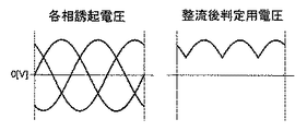
ここで、ブラシレスモータ5の誘起電圧を上記判定に用いるために、図2の整流回路204を用いる。整流回路204は、例えば、図6にあるような、ダイオードを用いた整流回路を用いる。整流をしない場合は、誘起電圧は3相を合計すると打ち消されてゼロになるが、整流回路204によって整流されることで、判定電圧として用いることが可能となる。図6に示すように、ブラシレスモータ5を構成する3相交流モータの誘起電圧は、モータ電気角1周期につき、U相、V相、W相、と3相の誘起電圧のピークがある。この内の1相のみを判定に使う場合より、3相を整流した電圧の方が、3相のうち、他相に比べて大きい相の誘起電圧で判定することができるため、より早く、ブラシレスモータ5の回転角速度の変化を読み取ることが可能となる。これにより、第2演算周期を長くすることができ、消費電流低減効果が向上する。
Here, in order to use the induced voltage of the brushless motor 5 for the above determination, the
図6では、整流回路204として、半波整流回路を例示しているが、より早い判定が必要となる場合には、全波整流回路を用いることも可能である。
In FIG. 6, a half-wave rectifier circuit is illustrated as the
また、図2に示すように、整流回路204には、モータ回転状態検出手段203が接続されている。モータ回転状態検出手段203は、図6に示すように、増幅回路203aとコンパレータ回路203bとを有している。増幅回路203aの増幅率は、モノリシックIC200に接続される抵抗器(図示せず)の抵抗値により設定される。増幅回路203aから出力される誘起電圧とコンパレータ回路203bに予め設定された所定の判定閾値(所定のバンドギャップ電圧)との比較により、ブラシレスモータ5の回転状態の判定を行う。
Further, as shown in FIG. 2, the motor rotation state detecting means 203 is connected to the
まず、副演算手段102の第2演算周期を長くするために、整流回路204による整流後の誘起電圧を、増幅回路203aによって増幅する。これにより、ブラシレスモータ5の誘起電圧が低い、つまり、ブラシレスモータ5が低回転の状態でも、読み飛ばしが発生するかどうかを判定することが可能となる。これにより、第2演算周期をより長くすることが可能となる。また、ブラシレスモータ5によっては、誘起電圧定数が異なるため、その差異を、増幅回路203aのゲインで調整することも可能である。
First, in order to lengthen the second calculation cycle of the sub calculation means 102, the induced voltage after rectification by the
さらに、増幅回路203aによる増幅後の誘起電圧を、コンパレータ回路203bへと入力する。コンパレータ回路203bには、予め所定の判定閾値が設定されている。コンパレータ回路203bに入力された誘起電圧が、判定閾値を超えた時、第2演算周期を切り替える。また、コンパレータ回路203bの入力は、ヒステリシスを設ける。整流回路204として、前記半波整流回路を用いた場合には、脈流の振幅よりもヒステリシス幅を広く設定するべく、図8に示す、コンパレータ回路203bへの入力ヒステリシスの幅を、下式のように設定することで、チャタリングが防止できる。
Further, the induced voltage after amplification by the amplifier circuit 203a is input to the comparator circuit 203b. A predetermined determination threshold is set in advance in the comparator circuit 203b. When the induced voltage input to the comparator circuit 203b exceeds the determination threshold, the second calculation cycle is switched. The input of the comparator circuit 203b provides hysteresis. When the half-wave rectifier circuit is used as the
Vth_high > Vht_low × 2 Vth_high> Vht_low × 2
このように、モータ回転状態判定手段203は、整流後のモータ誘起電圧を増幅する増幅回路203aと、ヒステリシスを持つコンパレータ回路203bとからなる。
As described above, the motor rotation
また、図2に示す本実施の形態では、第2監視手段201、レゾルバI/F第2回路202、および、モータ回転状態検出手段203を、モノリシックIC200としている。これにより実装時の面積を小さくすることができる。
Further, in the present embodiment shown in FIG. 2, the second monitoring unit 201, the resolver I / F
モノリシックIC200として構成した場合に、コンパレータ回路203bの判定閾値は、バンドギャップの制約を受けてしまい、モータ特性が異なるシステムでの判定の場合に適用できなくなる可能性があるが、増幅回路203aによって、整流後のモータ誘起電圧と、判定閾値との差をゲインで調整することで、適用可能となる。
When configured as the
以下に、本実施の形態1に係るモータ制御装置の効果について説明する。 The effects of the motor control device according to the first embodiment will be described below.
上述のように、本実施の形態1に係るモータ制御装置は、ブラシレスモータ5の回転角度を検出するためのレゾルバ6(モータ回転角度検出手段)と、主演算手段101および副演算手段102を有するコントローラ4とを備えている。主演算手段101は、ブラシレスモータ5を制御するための演算をする第1の動作状態と、当該演算をしていない第2の動作状態をとる。副演算手段102は、第1の動作状態においては、主演算手段101を監視し、第2の動作状態においては、モータ回転角度の演算をする。この構成により、主演算手段101がモータ制御を停止しても、副演算手段102により、モータ回転角度の検出を継続することが出来る。また、主演算手段101のモータ制御の演算負荷に比べ、副演算手段102のモータ回転角度演算の演算負荷が十分小さいので、主演算手段101と比べ、副演算手段102の消費電流が低減可能となり、第2の動作状態の消費電流を抑制することができる。以上により、モータ制御が停止している期間においても、低消費電流でモータ回転角度の演算を継続することが可能となる。
As described above, the motor control device according to the first embodiment includes the resolver 6 (motor rotation angle detection means) for detecting the rotation angle of the brushless motor 5, the main calculation means 101, and the sub calculation means 102. And a controller 4. The main calculation means 101 takes a first operation state in which a calculation for controlling the brushless motor 5 is performed and a second operation state in which the calculation is not performed. The sub calculation means 102 monitors the main calculation means 101 in the first operation state, and calculates the motor rotation angle in the second operation state. With this configuration, even if the main calculation unit 101 stops the motor control, the
また、第1および第2の動作状態において副演算手段102を監視するための第2監視手段201を、コントローラ4の外部に設けるようにしたので、副演算手段102の信頼性が向上する。
In addition, since the second monitoring unit 201 for monitoring the
また、第1電源301と、第1電源301より消費電流が少ない第2電源302とを備え、第2の動作状態では、主演算手段101は停止状態となり、副演算手段102は第2電源302から電力を供給される。これにより、第2の動作状態においては、第1電源301より消費電流が小さい第2電源302へ切り替えることで、消費電流を低減可能となる。
In addition, a
また、第1の動作状態では、主演算手段101および副演算手段102は、共に、第1電源301から電力を供給されるようにすると、第1の動作状態において、主演算手段101および副演算手段102がともに同じ電源を用いることとなり、電圧レベルを統一して監視を行うことが可能となり、誤判定を低減する。
Further, in the first operation state, when the main calculation unit 101 and the
また、主演算手段101は、第1の動作状態では、第1演算周期にてモータ回転角度の演算を行い、副演算手段102は、第2の動作状態では、第1の演算周期より長い第2演算周期にて、レゾルバ6からのモータ回転角度信号に基づいてモータ回転角度の演算を行う。このように、第2の動作状態において、第1の動作状態の第1演算周期より長い第2演算周期にてモータ回転角度の演算を行うことで、消費電流が低減可能となる。
Further, the main calculation means 101 calculates the motor rotation angle in the first calculation cycle in the first operation state, and the sub calculation means 102 determines the first calculation cycle longer than the first calculation cycle in the second operation state. The motor rotation angle is calculated based on the motor rotation angle signal from the
また、ブラシレスモータ5の回転角度を検出するためのモータ回転角度検出手段として、レゾルバ6を用い、レゾルバ6の励磁信号は、第2演算周期に同期したパルス信号で、かつ、当該励磁信号のオンの時間をオフの時間より短くすることで、消費電流を低減可能となる。
Further, a
また、レゾルバ6からのモータ回転角度信号のサンプルホールドを行うサンプルホールド手段を備え、サンプルホールド手段は、上記パルス信号がオン直後にサンプルし、オフする直前にホールドする。これにより、上記パルス信号のパルス幅や印加タイミングと関係なく、レゾルバ6からのモータ角度信号を得ることができる。
In addition, sample hold means for sample-holding the motor rotation angle signal from the
また、第2演算周期を、ブラシレスモータ5の回転速度が大きいほど短くするようにしたので、モータ回転速度が小さい場合に演算周期を長くしておくことができるため、消費電流を低減することが可能となる。 Further, since the second calculation cycle is shortened as the rotation speed of the brushless motor 5 is increased, the calculation cycle can be lengthened when the motor rotation speed is low, so that the current consumption can be reduced. It becomes possible.
また、第2演算周期を、ブラシレスモータ5の誘起電圧が大きいほど短くするようにしたので、ブラシレスモータ5の誘起電圧でモータ回転速度を判定することで、モータ回転速度を検出するための新たなセンサが不要となる。 Further, since the second calculation cycle is made shorter as the induced voltage of the brushless motor 5 is larger, a new rotational speed is detected by determining the motor rotational speed based on the induced voltage of the brushless motor 5. A sensor is unnecessary.
また、第2監視手段201と、レゾルバ6に励磁信号を印加するための励磁回路と、レゾルバ6からのモータ角度信号を副演算手段102に入力するための受信回路と、サンプルホールド手段と、ブラシレスモータ5の誘起電圧によってモータ回転状態を判定するモータ回転状態検出手段203とを、1つのモノリシックIC200として構成するようにしたので、基板上での実装面積が小さくでき、部品点数も削減可能となる。
Further, the second monitoring means 201, an excitation circuit for applying an excitation signal to the
また、モータ回転状態検出手段は、ブラシレスモータ5の誘起電圧を増幅する増幅回路203aを備え、モノリシックIC200に接続される抵抗器(図示せず)の抵抗値により、増幅回路203aの増幅率を設定し、増幅回路203aの出力電圧とモノリシックIC200内部に設定された所定のバンドギャップ電圧の比較により、ブラシレスモータ5の回転状態の判定を行うようにした。このようにモノリシックIC200を用いた場合、判定閾値の設定にバンドギャップの制約がある場合や、モータ特性の差異が発生した場合においても、適切な判定閾値をIC外部から設定できる。
The motor rotation state detection means includes an amplifier circuit 203a that amplifies the induced voltage of the brushless motor 5, and sets the amplification factor of the amplifier circuit 203a according to the resistance value of a resistor (not shown) connected to the
また、本実施の形態に係るモータ制御装置を電動パワーステアリング装置に利用することで、演算されたモータ回転角度から、操舵角を演算することが可能となる。 Further, by using the motor control device according to the present embodiment for the electric power steering device, the steering angle can be calculated from the calculated motor rotation angle.
実施の形態2.
以下、本発明を電動パワーステアリングシステムに適用した実施の形態2について、図9を用いて説明する。図9において、図1および図2と同一または相当する部分に付いては同一符号を付している。
A second embodiment in which the present invention is applied to an electric power steering system will be described below with reference to FIG. 9, parts that are the same as or correspond to those in FIGS. 1 and 2 are given the same reference numerals.
図9に示すように、本実施の形態2では、実施の形態1の主演算手段101と副演算手段102とが、一つの演算手段100を構成している。本構成は、演算手段を一つにすることで、コストおよび実装面積削減に寄与する。ただし、演算手段100が、ブラシレスモータを制御できるだけの能力および低消費電力であることが必要不可欠である。なお、本実施の形態においては、図2に示した第1監視手段106は設けられていない。他の構成は、図2と同じであるため、ここでは説明を省略する。
As shown in FIG. 9, in the second embodiment, the main calculation means 101 and the sub calculation means 102 of the first embodiment constitute one calculation means 100. This configuration contributes to cost and mounting area reduction by using a single arithmetic means. However, it is indispensable that the
なお、図9に示した構成において、本実施の形態に係るモータ制御装置は、コントローラ4、モノリシックIC200、レゾルバ6、整流回路204、遮断回路205、第2LPF206、第1電源301、および、第2電源302から、構成されている。但し、これらの構成はすべて設ける必要はなく、必要に応じて、適宜設けるようにしてもよい。
In the configuration shown in FIG. 9, the motor control device according to the present embodiment includes the controller 4, the
本実施の形態2のモータの制御については、演算手段100が、図2に記載の主演算手段101が行っているモータ制御と同じモータ制御を行う。 Regarding the control of the motor according to the second embodiment, the calculation means 100 performs the same motor control as the motor control performed by the main calculation means 101 shown in FIG.
まずは、IGスイッチ10がオンし、演算手段100によるモータ制御を行う第1の動作状態について説明をする。
First, the first operation state in which the IG switch 10 is turned on and the motor control by the
コントローラ4は、IGスイッチ10からのIGオン信号を受け取り、演算手段100がモータ制御を行う。演算手段100は、IGオン信号を受け取った後は、前述の通り、モータの回転角度を検出するレゾルバ6からのモータ回転角度信号をもとに、トルクセンサ3が検出したトルクに応じたアシストトルクを発生させるために、FETドライバ103へPWM制御信号を送る。FETドライバ103からの信号によって、PWMインバータ104は、前記アシストトルクを発生させるようブラシレスモータ5を通電する。演算手段100では、ブラシレスモータ5に通電された電流値が前記アシストトルクを発生させるための所望の値となるようにFETドライバ103へと信号を送り制御を行っている。
The controller 4 receives the IG ON signal from the IG switch 10, and the
また、この第1の動作状態においては、実施の形態1と同様に、レゾルバI/F第1回路105によって、正規励磁することによって、モータ回転角度信号を得る。
In the first operation state, the motor rotation angle signal is obtained by normal excitation by the resolver I / F
次に、IGスイッチ10がオフし、演算手段100によるモータ制御が停止している第2の動作状態について説明をする。 Next, the second operation state in which the IG switch 10 is turned off and the motor control by the computing means 100 is stopped will be described.
第2の動作状態では、演算手段100は、演算負荷の大きいモータ制御は停止するが、演算負荷の小さいモータ回転角度の演算は継続する。こうして、演算負荷の軽い処理のみを継続することになるので、消費電流が小さいモードでモータ回転角度を演算可能となる。 In the second operation state, the calculation means 100 stops the motor control with a large calculation load, but continues to calculate the motor rotation angle with a small calculation load. In this way, only processing with a light calculation load is continued, so that the motor rotation angle can be calculated in a mode with low current consumption.
また、第2の動作状態においては、実施の形態1と同様に、レゾルバI/F第2回路202を用いて間欠励磁を行うことで、モータ回転角度信号を得る。
Further, in the second operation state, similarly to the first embodiment, the motor rotation angle signal is obtained by performing intermittent excitation using the resolver I / F
また、演算手段100に対しては、第1の動作状態、かつ、第2の動作状態において、第2監視手段201によって、演算手段100の異常を監視をすることで、回転角度演算に対しての信頼性向上を実現する。監視手段201による監視の内容としては、ウインドウウォッチドッグタイマー、パワーオンリセット、低電圧検出、種々演算結果のチェック等がある。異常を検出した場合は、演算手段100のリセットを行う。 Further, for the calculation means 100, the second monitoring means 201 monitors the abnormality of the calculation means 100 in the first operation state and the second operation state, thereby preventing the calculation of the rotation angle. Realize improved reliability. The contents of the monitoring by the monitoring means 201 include a window watchdog timer, power-on reset, low voltage detection, and check of various calculation results. If an abnormality is detected, the calculation means 100 is reset.
演算手段100は、第2監視手段201によって、第1の動作状態、かつ、第2の動作状態において監視されているため、モータ回転角度に対しての信頼性を向上させることが可能となっている。
Since the
次に、消費電流を下げる方法について説明する。 Next, a method for reducing current consumption will be described.
まずは、演算手段100の電源を変更する方法について説明する。
IGスイッチ10によって演算手段100がモータ制御を停止している第2の動作状態においては、演算手段100は、消費電流を下げるために、第2電源302を用いて演算を継続する。
First, a method for changing the power supply of the computing means 100 will be described.
In the second operation state in which the
次に、消費電流を下げるため、演算手段100の演算周期を変更する方法について説明する。
本実施の形態においても、実施の形態1と同様に、図3に示すように、第2の動作状態での演算手段100の演算周期を、第1の動作状態の演算手段100の第1演算周期より長い第2演算周期に変更することにより、消費電流の低減を実現する。なお、第1演算周期および第2演算周期については、実施の形態1で説明したものと同じとする。
Next, a method for changing the calculation cycle of the calculation means 100 in order to reduce current consumption will be described.
Also in the present embodiment, as in the first embodiment, as shown in FIG. 3, the calculation cycle of the calculation means 100 in the second operation state is the first calculation of the calculation means 100 in the first operation state. By changing to the second calculation cycle longer than the cycle, reduction of current consumption is realized. The first calculation cycle and the second calculation cycle are the same as those described in the first embodiment.
モータ回転角度検出手段であるレゾルバ6を用いての間欠励磁動作については、実施の形態1と同様である。
The intermittent excitation operation using the
ところで、第2演算周期を長くする程、消費電流は低減できるのだが、実施の形態1と同様に、モータが第2演算周期で計測できるモータ回転角速度の限界を超えると、モータ回転角度を読み飛ばすことになってしまう。そこで、本実施の形態では、実施の形態1と同様に、演算手段100の演算周期を長くした時に、ブラシレスモータ5が第2演算周期で計測できるモータ回転角速度の限界を超える前に、図4に示すように、第2演算周期を短い周期へと切り替える。そのモータの回転角速度の判定のために、モータ回転状態検出手段203を用いる。 By the way, although the current consumption can be reduced as the second calculation cycle is lengthened, the motor rotation angle is read when the motor exceeds the limit of the motor rotation angular velocity that can be measured in the second calculation cycle, as in the first embodiment. Will be skipped. Therefore, in the present embodiment, as in the first embodiment, when the calculation cycle of the calculation means 100 is increased, before the brushless motor 5 exceeds the limit of the motor rotation angular velocity that can be measured in the second calculation cycle, FIG. As shown in FIG. 2, the second calculation cycle is switched to a shorter cycle. In order to determine the rotational angular velocity of the motor, motor rotation state detection means 203 is used.
モータ回転状態検出手段203の動作は、前記実施の形態1と同様である。 The operation of the motor rotation state detection means 203 is the same as that in the first embodiment.
また、本実施の形態においても、実施の形態1と同様に、図9に示すように、第2監視手段201、レゾルバI/F第2回路202、および、モータ回転状態検出手段203を、1つのモノリシックIC200とすることで、実装時の面積を小さくすることができる。レゾルバI/F第2回路202は、実施の形態1と同様に、励磁回路、受信回路、および、サンプルホールド手段からなる。また、モータ回転状態検出手段203は、整流後の誘起電圧を増幅する増幅回路と、ヒステリシスを持つコンパレータ回路とからなる。
Also in the present embodiment, as in the first embodiment, as shown in FIG. 9, the second monitoring unit 201, the resolver I / F
以上のように、本実施の形態2においても、上述した実施の形態1の効果と同じ効果が得られ、すなわち、モータ制御が停止している期間においても、信頼性を確保しながら、低消費電流でモータ回転角度の演算を継続することが可能となる。また、本実施の形態2では、演算手段として用いるマイコンを一個にしたため、コスト削減および実装面積削減が可能となる。 As described above, also in the second embodiment, the same effect as that of the first embodiment described above can be obtained. That is, even in a period in which the motor control is stopped, a low consumption is ensured while ensuring reliability. It becomes possible to continue the calculation of the motor rotation angle with the electric current. In the second embodiment, since one microcomputer is used as the calculation means, it is possible to reduce the cost and the mounting area.
1 ハンドル、2 操舵軸、3 トルクセンサ、4 コントローラ、5 ブラシレスモータ、6 レゾルバ、7 外部機器、8 車軸、9 バッテリー、10 IGスイッチ、 11 減速ギア、12 通信ライン、100 演算手段、101 主演算手段、102 副演算手段、103 FETドライバ、104 PWMインバータ、105 レゾルバI/F第1回路、106 第1監視手段、107 第1LPF、200 モノリシックIC、 201 第2監視手段、202 レゾルバI/F第2回路、203 モータ回転状態検出手段、204 整流回路、205 遮断回路、206 第2LPF。 1 steering wheel, 2 steering shaft, 3 torque sensor, 4 controller, 5 brushless motor, 6 resolver, 7 external device, 8 axle, 9 battery, 10 IG switch, 11 speed reduction gear, 12 communication line, 100 calculation means, 101 main calculation Means, 102 Sub-operation means, 103 FET driver, 104 PWM inverter, 105 first resolver I / F circuit, 106 first monitoring means, 107 first LPF, 200 monolithic IC, 201 second monitoring means, 202 resolver I / F second 2 circuits, 203 motor rotation state detection means, 204 rectifier circuit, 205 cutoff circuit, 206 second LPF.
Claims (13)
前記モータの制御を行う演算手段と、
前記演算手段の異常の有無を検出する監視手段と
を備え、
前記演算手段は、2つの動作状態を有し、
当該動作状態のうちの一つは、前記モータ回転角度検出手段からのモータ回転角度信号に基づいて前記モータの回転角度の演算を行い、演算した前記モータの回転角度に基づいて前記モータの制御を行う第1の動作状態であり、
当該動作状態のうちの他方は、前記モータの制御は停止し、前記モータ回転角度検出手段からのモータ回転角度信号に基づいて前記モータの回転角度の演算のみを行う第2の動作状態であり、
前記演算手段は、主演算手段と副演算手段とから構成され、
前記演算手段は、
前記第1の動作状態において、前記主演算手段を用いて、前記モータ回転角度検出手段からのモータ回転角度信号に基づいて前記モータの回転角度の演算を行い、演算した前記モータの回転角度に基づいて前記モータの制御を行い、
前記第2の動作状態において、前記主演算手段の動作を停止し、前記副演算手段を用いて、前記モータ回転角度検出手段からのモータ回転角度信号に基づいて前記モータの回転角度の演算を行い、
前記監視手段は、前記副演算手段内に設けられ、
前記副演算手段は、前記第1の動作状態において、前記監視手段を用いて、前記主演算手段の異常の有無を監視する
ことを特徴とするモータ制御装置。 Motor rotation angle detection means for outputting a motor rotation angle signal for detecting the rotation angle of the motor;
Arithmetic means for controlling the motor;
Monitoring means for detecting the presence or absence of abnormality of the computing means,
The computing means has two operating states,
One of the operation states is to calculate the rotation angle of the motor based on the motor rotation angle signal from the motor rotation angle detection means, and to control the motor based on the calculated rotation angle of the motor. A first operating state to perform,
Other of the operating conditions, control of the motor is stopped, Ri second operating state der performing only calculation of the rotation angle of the motor based on the motor rotational angle signal from the motor rotation angle detection means ,
The calculation means is composed of a main calculation means and a sub calculation means,
The computing means is
In the first operating state, the main calculation means is used to calculate the rotation angle of the motor based on the motor rotation angle signal from the motor rotation angle detection means, and based on the calculated rotation angle of the motor. To control the motor,
In the second operation state, the operation of the main calculation means is stopped, and the rotation angle of the motor is calculated based on the motor rotation angle signal from the motor rotation angle detection means using the sub calculation means. ,
The monitoring means is provided in the sub-calculation means,
The motor control device according to claim 1, wherein the sub-calculation means monitors the presence or absence of an abnormality of the main calculation means using the monitoring means in the first operating state .
前記第1監視手段は、前記副演算手段内に設けられ、
前記副演算手段は、前記第1の動作状態において、前記第1監視手段を用いて、前記主演算手段の異常の有無を監視し、
前記第2監視手段は、前記副演算手段の外部に設けられ、前記第1の動作状態および前記第2の動作状態において、前記副演算手段の異常の有無を監視する
ことを特徴とする請求項1に記載のモータ制御装置。 The monitoring means comprises a first monitoring means and a second monitoring means,
The first monitoring means is provided in the sub-calculation means,
The sub calculation means monitors the presence or absence of abnormality of the main calculation means using the first monitoring means in the first operating state,
The said 2nd monitoring means is provided in the exterior of the said sub calculating means, and monitors the presence or absence of abnormality of the said sub calculating means in the said 1st operation state and the said 2nd operation state. the motor control device according to 1.
前記第1の電源より消費電流が少ない第2の電源と
をさらに備え、
前記副演算手段は、前記第2の動作状態においては、前記第2の電源から電力が供給される
ことを特徴とする請求項1または2に記載のモータ制御装置。 A first power source for supplying power to the main computing means and the sub-calculating means;
A second power source that consumes less current than the first power source,
The sub calculation means, wherein in the second operating state, the motor control device according to claim 1 or 2, characterized in that the electric power is supplied from the second power supply.
ことを特徴とする請求項3に記載のモータ制御装置。 The first power supply supplies power to the main calculation means and the sub calculation means in the first operation state, and to both the main calculation means and the sub calculation means in the second operation state. The motor control device according to claim 3 , wherein no electric power is supplied.
前記第1の電源より消費電流が少ない第2の電源と
をさらに備え、
前記演算手段は、前記第1の動作状態においては、前記第1の電源から電力が供給され、前記第2の動作状態においては、前記第2の電源から電力が供給される
ことを特徴とする請求項1に記載のモータ制御装置。 A first power source for supplying power to the computing means;
A second power source that consumes less current than the first power source,
The computing means is supplied with power from the first power source in the first operating state, and is supplied with power from the second power source in the second operating state. The motor control device according to claim 1.
前記第2の演算周期は、前記第1の演算周期より長い
ことを特徴とする請求項1ないし5のいずれか1項に記載のモータ制御装置。 The calculation means calculates the rotation angle of the motor in a predetermined first calculation cycle in the first operation state, and in a predetermined second calculation cycle in the second operation state. Calculate the rotation angle of the motor,
Said second operation cycle, the motor control device according to any one of claims 1 to 5, characterized in that longer than the first operation cycle.
前記サンプルホールド手段は、前記パルス信号がオン直後にサンプルし、オフする直前にホールドする
ことを特徴とする請求項7に記載のモータ制御装置。 Sample hold means for performing sample hold of the motor rotation angle signal from the resolver,
The motor control apparatus according to claim 7 , wherein the sample hold means samples the pulse signal immediately after being turned on and holds the pulse signal immediately before being turned off.
前記電動パワーステアリング装置は、前記モータ制御装置が演算した前記モータの回転角度から操舵角を演算することを特徴とする請求項1ないし12のいずれか1項に記載のモータ制御装置。 The motor control device is mounted on an electric power steering device,
The electric power steering apparatus, the motor control device motor control apparatus according to any one of claims 1 to 12, characterized in that for calculating a steering angle from the rotation angle of the motor computed.
Priority Applications (3)
| Application Number | Priority Date | Filing Date | Title |
|---|---|---|---|
| JP2011097993A JP5389101B2 (en) | 2011-04-26 | 2011-04-26 | Motor control device |
| US13/253,292 US8810175B2 (en) | 2011-04-26 | 2011-10-05 | Motor control device |
| EP11184618.4A EP2517947B1 (en) | 2011-04-26 | 2011-10-11 | Motor control device |
Applications Claiming Priority (1)
| Application Number | Priority Date | Filing Date | Title |
|---|---|---|---|
| JP2011097993A JP5389101B2 (en) | 2011-04-26 | 2011-04-26 | Motor control device |
Publications (2)
| Publication Number | Publication Date |
|---|---|
| JP2012231588A JP2012231588A (en) | 2012-11-22 |
| JP5389101B2 true JP5389101B2 (en) | 2014-01-15 |
Family
ID=44860248
Family Applications (1)
| Application Number | Title | Priority Date | Filing Date |
|---|---|---|---|
| JP2011097993A Expired - Fee Related JP5389101B2 (en) | 2011-04-26 | 2011-04-26 | Motor control device |
Country Status (3)
| Country | Link |
|---|---|
| US (1) | US8810175B2 (en) |
| EP (1) | EP2517947B1 (en) |
| JP (1) | JP5389101B2 (en) |
Cited By (2)
| Publication number | Priority date | Publication date | Assignee | Title |
|---|---|---|---|---|
| EP3566929A1 (en) | 2018-05-09 | 2019-11-13 | Jtekt Corporation | Angle computing device and computing device |
| US11465683B2 (en) | 2017-04-18 | 2022-10-11 | Denso Corporation | Steering angle detection device |
Families Citing this family (25)
| Publication number | Priority date | Publication date | Assignee | Title |
|---|---|---|---|---|
| EP2778024B1 (en) * | 2011-11-07 | 2018-04-04 | JTEKT Corporation | Electrically operated power steering device |
| JP6024969B2 (en) | 2012-12-12 | 2016-11-16 | 株式会社ジェイテクト | Rotation angle detection device and electric power steering device having the same |
| JP6024970B2 (en) * | 2012-12-12 | 2016-11-16 | 株式会社ジェイテクト | Rotation angle detection device and electric power steering device having the same |
| JP6086205B2 (en) | 2012-12-12 | 2017-03-01 | 株式会社ジェイテクト | Phase difference detection device and rotation angle detection device including the same |
| JP6024971B2 (en) | 2012-12-12 | 2016-11-16 | 株式会社ジェイテクト | Rotation angle detector |
| JPWO2014148087A1 (en) * | 2013-03-19 | 2017-02-16 | 日立オートモティブシステムズ株式会社 | Power steering device and control device for power steering device |
| JP6202302B2 (en) * | 2013-04-11 | 2017-09-27 | 株式会社ジェイテクト | Rotation angle detector |
| JP6419426B2 (en) * | 2013-12-19 | 2018-11-07 | 日本電産エレシス株式会社 | Electronic control unit for electric power steering |
| JP5958572B2 (en) | 2014-02-27 | 2016-08-02 | 株式会社デンソー | Rotation angle detection device and electric power steering device using the same |
| JP6413384B2 (en) * | 2014-06-20 | 2018-10-31 | 株式会社ジェイテクト | Steering device |
| JP6040963B2 (en) | 2014-07-07 | 2016-12-07 | 株式会社デンソー | Rotating machine control device |
| JP2016032977A (en) * | 2014-07-31 | 2016-03-10 | 株式会社デンソー | Electric power steering system and vehicle control system |
| US10196085B2 (en) | 2015-02-26 | 2019-02-05 | Mitsubishi Electric Corporation | Electric power steering device |
| JP6657584B2 (en) * | 2015-03-31 | 2020-03-04 | 株式会社ジェイテクト | Rotation detection device, rotation angle detection device, and electric power steering device |
| US10328972B2 (en) * | 2016-04-06 | 2019-06-25 | Denso Corporation | Rotation detecting apparatus and electric power steering apparatus using the same |
| CN109247059B (en) * | 2016-05-13 | 2021-12-24 | 日本精工株式会社 | Motor drive control device, electric power steering device, and vehicle |
| JP6776179B2 (en) * | 2017-05-25 | 2020-10-28 | ルネサスエレクトロニクス株式会社 | Motor control system and semiconductor device |
| JP6984176B2 (en) * | 2017-05-26 | 2021-12-17 | 株式会社ジェイテクト | Rotation monitoring circuit |
| US20190280633A1 (en) * | 2018-03-07 | 2019-09-12 | GM Global Technology Operations LLC | Systems and methods for reducing code execution time in motor control systems |
| JP7155602B2 (en) * | 2018-05-17 | 2022-10-19 | 株式会社ジェイテクト | Arithmetic unit |
| JP7102923B2 (en) * | 2018-05-15 | 2022-07-20 | 株式会社ジェイテクト | Vehicle control device |
| EP3919871B1 (en) | 2020-04-08 | 2023-01-11 | NSK Ltd. | Rotational angle detecting device, electric power steering device, and control method of electric power steering device |
| EP3944487B1 (en) * | 2020-05-28 | 2023-03-01 | Huawei Digital Power Technologies Co., Ltd. | Motor angle detection and diagnosis device, motor controller, electric vehicle and method |
| CN112737462B (en) * | 2020-12-30 | 2023-03-24 | 杭州士兰微电子股份有限公司 | Method and device for identifying initial state of permanent magnet synchronous motor |
| CN114560009A (en) * | 2022-02-18 | 2022-05-31 | 恒大恒驰新能源汽车研究院(上海)有限公司 | Control system, method and device applied to automatic driving of vehicle |
Family Cites Families (26)
| Publication number | Priority date | Publication date | Assignee | Title |
|---|---|---|---|---|
| JPH0783626B2 (en) * | 1985-07-03 | 1995-09-06 | 株式会社日立製作所 | Induction motor controller |
| JP2960754B2 (en) * | 1990-07-06 | 1999-10-12 | 株式会社日立製作所 | Fan drive motor |
| JPH04242111A (en) * | 1991-01-14 | 1992-08-28 | Nippondenso Co Ltd | Steering-angle detecting apparatus for vehicle |
| JPH06098585A (en) * | 1992-09-14 | 1994-04-08 | Aisin Aw Co | Motor-driven vehicle |
| US5574346A (en) * | 1995-05-15 | 1996-11-12 | Delco Electronics Corporation | On and off state fault detection circuit for a multi-phase brushed or brushless DC motor |
| US5963706A (en) * | 1997-10-23 | 1999-10-05 | Baik; Edward Hyeen | Control system for multi-phase brushless DC motor |
| JP3463580B2 (en) * | 1998-10-21 | 2003-11-05 | トヨタ自動車株式会社 | Electric power steering device |
| US6392418B1 (en) * | 1999-09-16 | 2002-05-21 | Delphi Technologies, Inc. | Torque current comparison for current reasonableness diagnostics in a permanent magnet electric machine |
| JP3593050B2 (en) | 2001-03-27 | 2004-11-24 | 三菱電機株式会社 | Abnormality detection method and device for position detection device and electric power steering device |
| JP4830212B2 (en) * | 2001-05-16 | 2011-12-07 | 株式会社デンソー | Rotation angle sensor monitoring system |
| JP2003026024A (en) * | 2001-07-17 | 2003-01-29 | Omron Corp | Control device for electric power steering |
| JP3837317B2 (en) | 2001-10-03 | 2006-10-25 | 株式会社ジェイテクト | Vehicle steering system |
| JP3812739B2 (en) | 2002-05-28 | 2006-08-23 | 三菱電機株式会社 | Motor abnormality detection device and electric power steering control device |
| JP2004122943A (en) * | 2002-10-02 | 2004-04-22 | Unisia Jkc Steering System Co Ltd | Controller of electric power steering |
| JP4337452B2 (en) * | 2003-07-15 | 2009-09-30 | 株式会社ジェイテクト | Rotation angle detection device and rotation angle detection method |
| JP4342914B2 (en) * | 2003-11-10 | 2009-10-14 | ヤマハ発動機株式会社 | Position detection device and single axis robot, surface mounter, component testing device, SCARA robot equipped with the same |
| JP4296495B2 (en) * | 2004-02-03 | 2009-07-15 | 株式会社デンソー | Electric power steering device |
| US7459879B2 (en) | 2004-03-19 | 2008-12-02 | Mitsubishi Electric Corporation | Motor controller |
| JP4289458B2 (en) * | 2004-09-07 | 2009-07-01 | 三菱電機株式会社 | Electric power steering control device |
| JP2006322794A (en) | 2005-05-18 | 2006-11-30 | Hitachi Cable Ltd | Steering angle sensor |
| JP4899662B2 (en) * | 2006-06-28 | 2012-03-21 | 日本精工株式会社 | Control device for electric power steering device |
| KR101088976B1 (en) | 2007-04-16 | 2011-12-01 | 미쓰비시덴키 가부시키가이샤 | Electric motor controller |
| JP2009077503A (en) * | 2007-09-20 | 2009-04-09 | Hitachi Appliances Inc | Motor controller and controller for air conditioner |
| JP5396861B2 (en) | 2009-01-05 | 2014-01-22 | 日本精工株式会社 | Electric power steering device |
| JP5235741B2 (en) * | 2009-03-23 | 2013-07-10 | 日立オートモティブシステムズ株式会社 | Abnormality diagnosis device for power steering device |
| JP5338544B2 (en) * | 2009-07-28 | 2013-11-13 | 株式会社ジェイテクト | Electric power steering device |
-
2011
- 2011-04-26 JP JP2011097993A patent/JP5389101B2/en not_active Expired - Fee Related
- 2011-10-05 US US13/253,292 patent/US8810175B2/en active Active
- 2011-10-11 EP EP11184618.4A patent/EP2517947B1/en not_active Not-in-force
Cited By (2)
| Publication number | Priority date | Publication date | Assignee | Title |
|---|---|---|---|---|
| US11465683B2 (en) | 2017-04-18 | 2022-10-11 | Denso Corporation | Steering angle detection device |
| EP3566929A1 (en) | 2018-05-09 | 2019-11-13 | Jtekt Corporation | Angle computing device and computing device |
Also Published As
| Publication number | Publication date |
|---|---|
| EP2517947B1 (en) | 2015-02-25 |
| EP2517947A1 (en) | 2012-10-31 |
| US20120273290A1 (en) | 2012-11-01 |
| JP2012231588A (en) | 2012-11-22 |
| US8810175B2 (en) | 2014-08-19 |
Similar Documents
| Publication | Publication Date | Title |
|---|---|---|
| JP5389101B2 (en) | Motor control device | |
| US8558534B2 (en) | Rotational angle detection device and electric power steering system | |
| US7791293B2 (en) | Motor controller and electric power steering system | |
| JP5941871B2 (en) | Electric power steering device | |
| US9346486B2 (en) | Electric power steering system | |
| EP3090921B1 (en) | Vehicle steering angle detection apparatus, and electric power steering apparatus equipped with same | |
| US9359006B2 (en) | Electric power steering system | |
| JP6672993B2 (en) | Steering control device | |
| JP2007206018A (en) | Rotation angle detector, abnormality detector therefor, and motor-driven power steering unit | |
| JP7102923B2 (en) | Vehicle control device | |
| JP2016055678A (en) | Steering device and electric power steering device | |
| JP2010184669A (en) | Control device of electric power steering device | |
| EP2903151B1 (en) | Device for controlling electric motor | |
| JP6885171B2 (en) | Vehicle control device | |
| JP2009096325A (en) | Malfunction detecting device for steering device | |
| JP6223714B2 (en) | Electric power steering device | |
| JP5434216B2 (en) | Motor control device and electric power steering device | |
| JP2006162272A (en) | Torque detection apparatus | |
| JP3933656B2 (en) | Electric power steering device | |
| JP5726243B2 (en) | Motor control device |
Legal Events
| Date | Code | Title | Description |
|---|---|---|---|
| A977 | Report on retrieval |
Free format text: JAPANESE INTERMEDIATE CODE: A971007 Effective date: 20130404 |
|
| A131 | Notification of reasons for refusal |
Free format text: JAPANESE INTERMEDIATE CODE: A131 Effective date: 20130409 |
|
| TRDD | Decision of grant or rejection written | ||
| A01 | Written decision to grant a patent or to grant a registration (utility model) |
Free format text: JAPANESE INTERMEDIATE CODE: A01 Effective date: 20130910 |
|
| A61 | First payment of annual fees (during grant procedure) |
Free format text: JAPANESE INTERMEDIATE CODE: A61 Effective date: 20131008 |
|
| R150 | Certificate of patent or registration of utility model |
Ref document number: 5389101 Country of ref document: JP Free format text: JAPANESE INTERMEDIATE CODE: R150 Free format text: JAPANESE INTERMEDIATE CODE: R150 |
|
| R250 | Receipt of annual fees |
Free format text: JAPANESE INTERMEDIATE CODE: R250 |
|
| R250 | Receipt of annual fees |
Free format text: JAPANESE INTERMEDIATE CODE: R250 |
|
| R250 | Receipt of annual fees |
Free format text: JAPANESE INTERMEDIATE CODE: R250 |
|
| R250 | Receipt of annual fees |
Free format text: JAPANESE INTERMEDIATE CODE: R250 |
|
| R250 | Receipt of annual fees |
Free format text: JAPANESE INTERMEDIATE CODE: R250 |
|
| R250 | Receipt of annual fees |
Free format text: JAPANESE INTERMEDIATE CODE: R250 |
|
| R250 | Receipt of annual fees |
Free format text: JAPANESE INTERMEDIATE CODE: R250 |
|
| LAPS | Cancellation because of no payment of annual fees |