JP5387698B2 - Stator core - Google Patents
Stator core Download PDFInfo
- Publication number
- JP5387698B2 JP5387698B2 JP2011552605A JP2011552605A JP5387698B2 JP 5387698 B2 JP5387698 B2 JP 5387698B2 JP 2011552605 A JP2011552605 A JP 2011552605A JP 2011552605 A JP2011552605 A JP 2011552605A JP 5387698 B2 JP5387698 B2 JP 5387698B2
- Authority
- JP
- Japan
- Prior art keywords
- stator core
- circumferential direction
- caulking
- joint
- radial direction
- Prior art date
- Legal status (The legal status is an assumption and is not a legal conclusion. Google has not performed a legal analysis and makes no representation as to the accuracy of the status listed.)
- Active
Links
- 229910000831 Steel Inorganic materials 0.000 claims description 21
- 239000010959 steel Substances 0.000 claims description 21
- 238000010030 laminating Methods 0.000 claims description 3
- 239000011162 core material Substances 0.000 description 297
- 230000002093 peripheral effect Effects 0.000 description 15
- 230000011218 segmentation Effects 0.000 description 10
- 238000006243 chemical reaction Methods 0.000 description 6
- 230000007246 mechanism Effects 0.000 description 6
- 230000007423 decrease Effects 0.000 description 5
- 238000004519 manufacturing process Methods 0.000 description 5
- 229910000976 Electrical steel Inorganic materials 0.000 description 4
- 238000010586 diagram Methods 0.000 description 4
- 238000000034 method Methods 0.000 description 4
- 230000000694 effects Effects 0.000 description 3
- 230000009467 reduction Effects 0.000 description 3
- 229920005989 resin Polymers 0.000 description 3
- 239000011347 resin Substances 0.000 description 3
- 239000004412 Bulk moulding compound Substances 0.000 description 2
- 239000004734 Polyphenylene sulfide Substances 0.000 description 2
- 230000009471 action Effects 0.000 description 2
- 238000006073 displacement reaction Methods 0.000 description 2
- 229920001707 polybutylene terephthalate Polymers 0.000 description 2
- 229920000069 polyphenylene sulfide Polymers 0.000 description 2
- -1 Polybutylene Terephthalate Polymers 0.000 description 1
- 230000015572 biosynthetic process Effects 0.000 description 1
- 230000006835 compression Effects 0.000 description 1
- 238000007906 compression Methods 0.000 description 1
- 230000008878 coupling Effects 0.000 description 1
- 238000010168 coupling process Methods 0.000 description 1
- 238000005859 coupling reaction Methods 0.000 description 1
- 238000002788 crimping Methods 0.000 description 1
- 230000006866 deterioration Effects 0.000 description 1
- 239000003822 epoxy resin Substances 0.000 description 1
- 238000009413 insulation Methods 0.000 description 1
- 239000012212 insulator Substances 0.000 description 1
- 238000005304 joining Methods 0.000 description 1
- 230000004048 modification Effects 0.000 description 1
- 238000012986 modification Methods 0.000 description 1
- 239000004033 plastic Substances 0.000 description 1
- 229920000647 polyepoxide Polymers 0.000 description 1
- 230000001172 regenerating effect Effects 0.000 description 1
- 230000001105 regulatory effect Effects 0.000 description 1
- 229920005992 thermoplastic resin Polymers 0.000 description 1
- 229920001187 thermosetting polymer Polymers 0.000 description 1
Images


Classifications
-
- H—ELECTRICITY
- H02—GENERATION; CONVERSION OR DISTRIBUTION OF ELECTRIC POWER
- H02K—DYNAMO-ELECTRIC MACHINES
- H02K1/00—Details of the magnetic circuit
- H02K1/06—Details of the magnetic circuit characterised by the shape, form or construction
- H02K1/12—Stationary parts of the magnetic circuit
- H02K1/14—Stator cores with salient poles
- H02K1/146—Stator cores with salient poles consisting of a generally annular yoke with salient poles
- H02K1/148—Sectional cores
-
- H—ELECTRICITY
- H02—GENERATION; CONVERSION OR DISTRIBUTION OF ELECTRIC POWER
- H02K—DYNAMO-ELECTRIC MACHINES
- H02K2201/00—Specific aspects not provided for in the other groups of this subclass relating to the magnetic circuits
- H02K2201/09—Magnetic cores comprising laminations characterised by being fastened by caulking
-
- H—ELECTRICITY
- H02—GENERATION; CONVERSION OR DISTRIBUTION OF ELECTRIC POWER
- H02K—DYNAMO-ELECTRIC MACHINES
- H02K2213/00—Specific aspects, not otherwise provided for and not covered by codes H02K2201/00 - H02K2211/00
- H02K2213/03—Machines characterised by numerical values, ranges, mathematical expressions or similar information
Landscapes
- Engineering & Computer Science (AREA)
- Power Engineering (AREA)
- Iron Core Of Rotating Electric Machines (AREA)
Description
本発明は、ステータコアに関し、特に、回転電機のステータに使用されるステータコアに関する。 The present invention relates to a stator core, and more particularly to a stator core used for a stator of a rotating electrical machine.
回転電機用ステータコアに関し、従来、種々の技術が提案されている。たとえば特開2006−352991号公報(特許文献1)には、帯状コア素材の片端の端面に凹部を、反対側の端の端面に凸部を設け、塑性変形させて筒状とする場合にそれらを嵌合させて結合を達成し、凹部の口元、凸部の首部分に縊れ部を設けることにより嵌合後の抜け防止とする、ステータコアが提案されている。 Conventionally, various techniques have been proposed for stator cores for rotating electrical machines. For example, in Japanese Patent Application Laid-Open No. 2006-352991 (Patent Document 1), a concave portion is provided on one end face of a belt-shaped core material, and a convex portion is provided on an end face on the opposite end, and these are formed into a cylindrical shape by plastic deformation. A stator core has been proposed that achieves coupling by fitting and providing a necked portion at the mouth of the concave portion and the neck portion of the convex portion to prevent slipping after the fitting.
特開2006−340509号公報(特許文献2)には、分割ステータコア間の接合面を略台形の凹凸形状とし、他の分割ステータコアとの接合面積を大きくして磁気抵抗を低減する技術が提案されている。特開2007−129835号公報(特許文献3)には、分割ステータコア間の接合面を凹凸形状とし、外周側当接部よりも内周側当接部の当接圧力を大きくする技術が提案されている。特開2008−206262号公報(特許文献4)には、分割ステータコア間の接合面を段差形状とし、平面視で凹凸形状とする技術が提案されている。 Japanese Patent Application Laid-Open No. 2006-340509 (Patent Document 2) proposes a technique for reducing the magnetic resistance by making the joint surface between the split stator cores into a substantially trapezoidal uneven shape and increasing the joint area with other split stator cores. ing. Japanese Patent Application Laid-Open No. 2007-129835 (Patent Document 3) proposes a technique in which the joint surface between the divided stator cores is formed in a concavo-convex shape so that the contact pressure of the inner peripheral contact portion is larger than the outer peripheral contact portion. ing. Japanese Patent Application Laid-Open No. 2008-206262 (Patent Document 4) proposes a technique in which the joint surface between the divided stator cores has a stepped shape, and has an uneven shape in plan view.
特開2006−352991号公報(特許文献1)に記載のステータコアでは、ステータコアのヨーク部に形成された凹部に凸部を圧入して嵌合する。そのため、分割ステータコアの組み付け時に周方向に加圧する必要があり、組み付け性が悪い。 In the stator core described in Japanese Patent Application Laid-Open No. 2006-352991 (Patent Document 1), a convex portion is press-fitted and fitted into a concave portion formed in a yoke portion of the stator core. Therefore, it is necessary to pressurize in the circumferential direction when the divided stator core is assembled, and the assemblability is poor.
一方、分割ステータコアが環状に配置された状態で外筒が焼バメされることによって、分割ステータコアが固定され、筒状のステータコアが形成される。外周側から焼バメされるために、分割ステータコアには径方向内方の応力が作用する。このとき、ステータコアの剛性が低いと、外筒の精度に従ってステータコアの位置決め精度が悪化する、座屈が発生するなどの問題が発生する。外筒からの応力の作用に対し、分割ステータコアの位置決め精度を確保することにより、ステータコアの真円度を向上させる必要がある。また、応力による分割ステータコアの座屈を抑制するために、分割ステータコアの剛性を向上させる必要がある。 On the other hand, when the outer cylinder is baked in a state where the divided stator core is annularly arranged, the divided stator core is fixed and a cylindrical stator core is formed. Due to the shrinkage from the outer peripheral side, radially inward stress acts on the split stator core. At this time, if the rigidity of the stator core is low, problems such as deterioration of the positioning accuracy of the stator core according to the accuracy of the outer cylinder and occurrence of buckling occur. It is necessary to improve the roundness of the stator core by ensuring the positioning accuracy of the divided stator core against the action of stress from the outer cylinder. Moreover, in order to suppress the buckling of the split stator core due to stress, it is necessary to improve the rigidity of the split stator core.
本発明は上記の問題に鑑みてなされたものであり、その主たる目的は、分割ステータコアを容易に組み付け可能とし、かつ、分割ステータコアの位置決め精度および剛性を向上できる、ステータコアを提供することである。 The present invention has been made in view of the above problems, and a main object of the present invention is to provide a stator core capable of easily assembling a split stator core and improving the positioning accuracy and rigidity of the split stator core.
本発明に係るステータコアは、複数の分割ステータコアを備える。分割ステータコアは、環状に配置されている。分割ステータコアは、複数の鋼板が軸方向に積層されて形成されている。分割ステータコアは、周方向に延在するヨーク部と、ヨーク部から径方向内側に突出する二つのティース部とを含む。ヨーク部は、周方向の一端に設けられた第一接合部と、周方向の他端に設けられた第二接合部を有する。第一接合部と第二接合部とは、分割ステータコアが環状に配置されたときに、分割ステータコアと隣接する他の分割ステータコアとを接合する。第一接合部には、隣接する他の分割ステータコアに向かって突起する突起部が形成されている。突起部は、軸方向に垂直な断面形状が略台形形状であり、径方向における突起部の先端部の長さと根元部の長さとの比を3:4とするように形成されている。第二接合部には、突起部を収容可能な窪み部が形成されている。窪み部は、軸方向に垂直な断面形状が略台形形状であり、窪み部の最深部から窪み部の開口部へ向かって開口面積が増加し、径方向における窪み部の最深部の長さと開口部の長さとの比を3:4とするように形成されている。突起部を窪み部に嵌合するとき、突起部の略台形形状の斜辺と窪み部の略台形形状の斜辺とが面接触する。ヨーク部の、二つのティース部のうち第一接合部に近い側のティース部の周方向における中心部よりも第一接合部に近接する位置であって、一端が周方向に押圧されることによる応力が集中する部分に、分割ステータコアを軸方向にかしめて鋼板を一体化する、第一のかしめ部が形成されている。 The stator core according to the present invention includes a plurality of divided stator cores. The divided stator core is arranged in an annular shape. The split stator core is formed by laminating a plurality of steel plates in the axial direction. The split stator core includes a yoke portion extending in the circumferential direction and two teeth portions protruding radially inward from the yoke portion. The yoke portion has a first joint provided at one end in the circumferential direction and a second joint provided at the other end in the circumferential direction. The first joint portion and the second joint portion join the split stator core and another split stator core adjacent to each other when the split stator core is arranged in an annular shape. The first joint is formed with a protrusion that protrudes toward another adjacent divided stator core. The protrusion has a substantially trapezoidal cross-sectional shape perpendicular to the axial direction, and is formed so that the ratio of the length of the tip portion to the length of the root portion in the radial direction is 3: 4. The second joint is formed with a recess that can accommodate the protrusion. The hollow portion has a substantially trapezoidal cross-sectional shape perpendicular to the axial direction, the opening area increases from the deepest portion of the hollow portion toward the opening portion of the hollow portion, and the length and opening of the deepest portion of the hollow portion in the radial direction It is formed so that the ratio to the length of the part is 3: 4. When the protrusion is fitted into the depression, the substantially trapezoidal hypotenuse of the projection and the substantially trapezoidal hypotenuse of the depression come into surface contact. Of the two teeth portions of the yoke portion, the position closer to the first joint portion than the center portion in the circumferential direction of the tooth portion closer to the first joint portion, one end being pressed in the circumferential direction A first caulking portion is formed in the portion where the stress is concentrated, by caulking the split stator core in the axial direction and integrating the steel plates.
上記ステータコアにおいて好ましくは、ヨーク部には、周方向における二つのティース部の中央に、分割ステータコアを軸方向にかしめる第二のかしめ部が形成されている。 Preferably, in the stator core, a second caulking portion for caulking the divided stator core in the axial direction is formed in the center of the two teeth portions in the circumferential direction.
上記ステータコアにおいて好ましくは、ヨーク部の第二接合部近傍に、分割ステータコアを軸方向にかしめる第三のかしめ部が形成されている。周方向における第一のかしめ部と第二のかしめ部との間隔は、周方向における第二のかしめ部と第三のかしめ部との間隔に等しい。 In the stator core, preferably, a third caulking portion for caulking the divided stator core in the axial direction is formed in the vicinity of the second joint portion of the yoke portion. The interval between the first caulking portion and the second caulking portion in the circumferential direction is equal to the interval between the second caulking portion and the third caulking portion in the circumferential direction.
上記ステータコアにおいて好ましくは、第一のかしめ部と第三のかしめ部とは、周方向に対称な位置に形成されている。 In the stator core, preferably, the first caulking portion and the third caulking portion are formed at symmetrical positions in the circumferential direction.
上記ステータコアにおいて好ましくは、突起部の先端部と根元部との間の周方向の距離と、先端部の径方向の長さと、根元部の径方向の長さとの比を、0.75〜1:3:4とし、窪み部の開口部と最深部との間の周方向の距離と、最深部の径方向の長さと、開口部の径方向の長さとの比を、0.75〜1:3:4とする。 Preferably, in the stator core, a ratio of a circumferential distance between the tip portion and the root portion of the protrusion, a radial length of the tip portion, and a radial length of the root portion is set to 0.75 to 1. : 3: 4, and the ratio of the circumferential distance between the opening and the deepest part of the recess, the radial length of the deepest part, and the radial length of the opening is 0.75 to 1 : 3: 4.
本発明のステータコアによると、分割ステータコアを容易に組み付けることができ、かつ、分割ステータコアの位置決め精度および剛性を向上することができる。 According to the stator core of the present invention, the split stator core can be easily assembled, and the positioning accuracy and rigidity of the split stator core can be improved.
以下、図面に基づいてこの発明の実施の形態を説明する。なお、以下の図面において、同一または相当する部分には同一の参照番号を付し、その説明は繰返さない。 Embodiments of the present invention will be described below with reference to the drawings. In the following drawings, the same or corresponding parts are denoted by the same reference numerals, and description thereof will not be repeated.
(実施の形態1)
図1は、実施の形態1のステータコアが適用されるステータ140を備える、ハイブリッド車両(HV:hybrid vehicle)の構成を示す概略図である。図1に示すように、ハイブリッド車両は、回転電機10と、回転シャフト30と、減速機構40と、ディファレンシャル機構50と、ドライブシャフト受け部60とを備える。電動機または発電機としての機能を有する回転電機(モータジェネレータ)10は、ロータ20と、ステータ140とを含む。(Embodiment 1)
FIG. 1 is a schematic diagram illustrating a configuration of a hybrid vehicle (HV) including a
ロータ20は、回転シャフト30に組付けられる。ロータ20には、図示しない永久磁石が埋設されている。すなわち、回転電機10はIPM(Interior Permanent Magnet)モータである。回転シャフト30は、軸受を介在させて、ハイブリッド車両の駆動ユニットのハウジング部に回転可能に支持されている。ロータ20は、回転シャフト30に固設され、回転シャフト30と共に回転可能に設けられている。環状のステータ140は、ロータ20の周囲に設けられており、ロータ20の外周に配置されている。
The
ステータ140の軸方向端面177a,177bには、コイル180が装着されている。コイル180は、コイルエンド部182を有する。コイルエンド部182は、ステータ140の軸方向端面177aに対して、図1中に両矢印で示す軸方向DR1に突出している。コイルエンド部182には、端子台110が設置されている。端子台110は、ステータ140の軸方向端部に設置されている。コイルエンド部182と端子台110とは、絶縁性のモールド樹脂部183によって、一体として固定されている。このモールド樹脂部183は、たとえばBMC(Bulk Molding Compound)、エポキシ樹脂などの熱硬化性樹脂や、PPS(Polyphenylene Sulfide)、PBT(Polybutylene Terephthalate)などの熱可塑性樹脂などを含んでいる。
A
コイル180は、端子台110を介在させて、3相ケーブル90によってPCU(Power Control Unit)70と電気的に接続されている。3相ケーブル90は、U相ケーブル91、V相ケーブル92およびW相ケーブル93からなる。コイル180は、U相コイル、V相コイルおよびW相コイルからなり、これらの3つのコイルの端子に、それぞれ、U相ケーブル91、V相ケーブル92およびW相ケーブル93が接続されている。またPCU70は、給電ケーブルによってバッテリ80と電気的に接続されている。これにより、バッテリ80とステータ140とが電気的に接続されている。
The
ロータ20およびステータ140を含む回転電機10から出力された駆動力は、減速機構40からディファレンシャル機構50を経由して、ドライブシャフト受け部60に伝達される。ドライブシャフト受け部60に伝達された駆動力は、図示しないドライブシャフトを経由して図示しない駆動輪に回転力として伝達されて、ハイブリッド車両を走行させる。
The driving force output from the rotating
一方、ハイブリッド車両の回生制動時には、駆動輪は車体の慣性力により回転させられる。駆動輪からの回転力によりドライブシャフト受け部60、ディファレンシャル機構50および減速機構40を経由して、回転電機10が駆動される。このとき、回転電機10は、発電機として作動する。回転電機10により発電された電力は、PCU70内のインバータを経由して、バッテリ80に蓄えられる。
On the other hand, at the time of regenerative braking of the hybrid vehicle, the drive wheels are rotated by the inertial force of the vehicle body. The rotating
図2は、軸方向DR1から平面視したステータ140の一部を示す図である。図2に示すように、ステータ140は、断面形状環状の筒状に形成されたステータコア141と、このステータコア141の外周に装着されたリング181とを備える。ステータコア141は、周方向に分割された複数の分割ステータコア175を備える。各分割ステータコア175が、周方向に配列され環状に配置されることで、筒状のステータコア141が形成されている。ステータコア141の周方向DR2と径方向DR3とを、図2中に両矢印で示す。
FIG. 2 is a view showing a part of the
各々の分割ステータコア175は、ステータコア141の周方向DR2に延在する円環状のヨーク部176を含む。各々の分割ステータコア175はまた、このヨーク部176からステータコア141の径方向DR3の内側に向けて突出する二つのティース部としての、ステータティース171,172をさらに含む。ステータティース171,172は、周方向DR2に沿って、等間隔に形成されている。ステータ140は、環状に延びるヨーク部176と、このヨーク部176の内周面から径方向内方に向けて突出する複数のステータティース171,172とを備えている。
Each divided
ステータコア141の周方向DR2において隣り合うステータティース171,172間には、スロットが形成されている。図1に示すコイル180は、このスロット内に収容され、ステータティース171,172に巻回されて、分割ステータコア175に装着される。コイル180と分割ステータコア175との間には、コイル180と分割ステータコア175との間の絶縁を確保する、図示しないインシュレータが介在している。
Slots are formed between the
環状に配列された分割ステータコア175の外周側には、リング181が装着されている。リング181によって各分割ステータコア175が固定され、環状のステータコア141を形成している。
A
周方向DR2に延在するヨーク部176の、周方向DR2の両端部のうちの一方の端部である一端には、第一接合部178が設けられ、他方の端部である他端には第二接合部179が設けられている。ヨーク部176は、周方向DR2の両端に設けられた、第一接合部178および第二接合部179を有する。分割ステータコア175が環状に配置されたときに、第一接合部178は、分割ステータコア175と、周方向DR2の一方側に隣接する他の分割ステータコアとを接合する。第二接合部179は、分割ステータコア175と、周方向DR2の他方側に隣接する他の分割ステータコアとを接合する。
A first joint 178 is provided at one end of one end of both ends in the circumferential direction DR2 of the
分割ステータコア175の第一接合部178は、当該分割ステータコア175に対して周方向DR2に隣接する、他の分割ステータコア175の第二接合部179と、当接している。分割ステータコア175の第二接合部179は、当該分割ステータコア175に対して周方向DR2に隣接する、他の分割ステータコア175の第一接合部178と、当接している。第一接合部178と第二接合部179とは、分割ステータコア175と隣接する他の分割ステータコアとを周方向DR2に連結する、周方向連結部として機能する。
The
ヨーク部176の第一接合部178近傍には、分割ステータコア175を図2の紙面垂直方向である軸方向DR1にかしめるかしめ部187が形成されている。ヨーク部176の、周方向DR2における二つのステータティース171,172の中央には、分割ステータコア175を軸方向DR1にかしめる第二のかしめ部としての、かしめ部186が形成されている。ヨーク部176の第二接合部179近傍には、分割ステータコア175を軸方向DR1にかしめる第三のかしめ部としての、かしめ部185が形成されている。かしめ部186に対し径方向DR3内側には、第四のかしめ部としてのかしめ部188が形成されている。
In the vicinity of the
分割ステータコア175は、複数の電磁鋼板が軸方向DR1に積層されて形成されている。分割ステータコア175が複数の電磁鋼板から形成される場合、かしめ部185〜188によって軸方向DR1に電磁鋼板が互いにかしめ固定され一体化されることにより、一体の分割ステータコア175が形成される。
The divided
図3は、図2に示すステータコア141の分解図である。図3に示すように、第一接合部178は、径方向DR3に沿って延びる内径側の近傍面191と、径方向DR3に沿って延びる外径側の遠方面192と、近傍面191および遠方面192の間の突起部193とを含む。第一接合部178には、突起部193が形成されている。近傍面191、遠方面192および突起部193は、周方向DR2に延在するヨーク部176の第一の周方向端面を形成する。分割ステータコア175の突起部193は、当該分割ステータコア175に対して周方向DR2に隣接する、他の分割ステータコアに向かって突起する。
FIG. 3 is an exploded view of the
第二接合部179は、径方向DR3に沿って延びる内径側の近傍面197と、径方向DR3に沿って延びる外径側の遠方面195と、近傍面197および遠方面195の間の窪み部196とを含む。第二接合部179には、窪み部196が形成されている。近傍面197、遠方面195および窪み部196は、周方向DR2に延在するヨーク部176の第二の周方向端面を形成する。分割ステータコア175の窪み部196は、当該分割ステータコア175に対して周方向DR2に隣接する、他の分割ステータコアの第一接合部178に対して窪んだ凹形状に形成されている。窪み部196は、突起部193を収容可能な形状に形成されている。
The second
第一接合部178に含まれる突起部193は、図3の紙面垂直方向である軸方向DR1に垂直な形状が、略台形形状であるように形成されている。第二接合部179に含まれる窪み部196は、図3の紙面垂直方向である軸方向DR1に垂直な形状が、略台形形状であるように形成されている。突起部193および窪み部196は、軸方向DR1に垂直な断面形状が略台形形状であるように形成されている。
The
図4は、図3に示す分割ステータコア175の、第二接合部179付近を拡大した図である。図4に示すように、略台形形状に形成された窪み部196は、周方向DR2において窪みが開口する開口部196aと、窪みの底部分を形成する最深部196bと、最深部196bから開口部196aへ至るように延びる側壁部196c,196dと、を有する。開口部196aは窪み部196が形成する台形の下底に相当する。最深部196bは窪み部196が形成する台形の上底に相当する。側壁部196c,196dは窪み部196が形成する台形の上底と下底とを結ぶ斜辺に相当する。
FIG. 4 is an enlarged view of the vicinity of the
第二接合部179の近傍面197と遠方面195とが径方向DR3に延びる同一の平面上に形成され、かつ最深部196bが径方向DR3に延びる平面として形成されると、開口部196aが形成する平面と最深部196bが形成する平面とがほぼ平行になり、窪み部196はほぼ台形の形状となる。また、近傍面197と遠方面195とが径方向DR3に延びる同一の平面上に形成され、当該平面と平行な面上に最深部196bが形成されて、窪み部196が台形形状に形成されてもよい。側壁部196c,196dは、図4に示す平面上、すなわち分割ステータコア175の軸方向DR1に垂直な断面上で、同一の長さを有してもよく、この場合窪み部196は略等脚台形の形状に形成される。
When the
窪み部196は、略台形形状に形成されているために、窪み部196の最深部196bから窪み部196の開口部196aへ向かって開口面積が増加する。ここで開口面積とは、窪み部196の深さ方向に対し垂直な断面、つまり本実施の形態の場合、環状のステータコア141の周方向DR2に対し垂直な断面において、窪み部196により形成されるヨーク部176の開口の面積をいう。窪み部196の側壁部196c,196dは、周方向DR2に沿って最深部196bから開口部196aへ至るに従って徐々に窪み部196の開口面積が大きくなるように、すなわち窪み部196の径方向長さが増加するように、周方向DR2に対して傾斜している。
Since the
窪み部196は、図4に示すように、径方向長さr1の最深部196bを有し、径方向長さr2の開口部196aを有するように形成されている。図4に示す平面上で、最深部196bが形成する径方向に延びる長さr1の線分の中点と、開口部196aが形成する径方向に延びる長さr2の線分の中点とは、環状のステータコア141の中心軸に相当する点を中心とする同一の円上に配置されている。最深部196bが形成する線分の中点と、開口部196aが形成する線分の中点とは、周方向DR2に延びる同一の円弧上にある。かしめ部185は、上記円弧に沿って延在している。
As shown in FIG. 4, the
径方向DR3においてかしめ部185が形成されている位置は、径方向DR3に延びる最深部196bの径方向長さr1、および、開口部196aが形成する仮想的な径方向DR3に延びる平面の径方向長さr2の、中心点に相当する。かしめ部185は周方向DR2に沿って延び、かしめ部185が延在する曲線が最深部196bおよび開口部196aを径方向DR3に二等分するように、かしめ部185は形成されている。かしめ部185は、開口部196aの径方向長さr2の中央部を通り、周方向DR2に延びる円弧上に形成されており、かつ、最深部196bの径方向長さr1の中央部を通り、周方向DR2に延びる円弧上に形成されている。
The position where the
軸方向DR1に平面視した場合に、かしめ部185は、環状のステータコア141の中心軸に対応する点を中心とする円弧であって、径方向DR3における窪み部196の中心部を通る円弧上に、形成される。そのため、図4に示す平面上で、径方向DR3における最深部196bの端部とかしめ部185との距離は、最深部196bの径方向長さr1の半分、すなわちr1/2である。かつ、図4に示す平面上で、径方向DR3における開口部196aの端部とかしめ部185との距離は、開口部196aの径方向長さr2の半分、すなわちr2/2である。
When viewed in plan in the axial direction DR1, the
図5は、図3に示す分割ステータコア175の、第一接合部178付近を拡大した図である。図5に示すように、略台形形状に形成された突起部193は、周方向DR2において突起部193の先端を形成する先端部193aと、突起部193の根元を形成する根元部193bと、根元部193bから先端部193aへ至るように延びる側壁部193c,193dと、を有する。先端部193aは突起部193が形成する台形の上底に相当する。根元部193bは突起部193が形成する台形の下底に相当する。側壁部193c,193dは突起部193が形成する台形の上底と下底とを結ぶ斜辺に相当する。
FIG. 5 is an enlarged view of the vicinity of the
第一接合部178の近傍面191と遠方面192とが径方向DR3に延びる同一の平面上に形成され、かつ先端部193aが径方向DR3に延びる平面として形成されると、先端部193aが形成する平面と根元部193bが形成する平面とがほぼ平行になり、突起部193はほぼ台形の形状となる。また、近傍面191と遠方面192とが径方向DR3に延びる同一の平面上に形成され、当該平面と平行な面上に先端部193aが形成されて、突起部193が台形形状に形成されてもよい。側壁部193c,193dは、図5に示す平面上、すなわち分割ステータコア175の軸方向DR1に垂直な断面上で、同一の長さを有してもよく、この場合突起部193は略等脚台形の形状に形成される。
When the
突起部193は、略台形形状に形成されているために、突起部193の根元部193bから突起部193の先端部193aへ向かって幅狭になっている。すなわち、径方向DR3に沿う突起部193の長さは、突起部193の根元部193bから突起部193の先端部193aへ向かって、小さくなっている。突起部193の側壁部193c,193dは、周方向DR2に沿って根元部193bから先端部193aへ至るに従って徐々に突起部193の幅が狭くなるように、すなわち突起部193の径方向長さが減少するように、周方向DR2に対して傾斜している。突起部193が根元部193bから先端部193aへ向かって幅狭になるように、側壁部193c,193dには勾配が付けられている。
Since the protruding
突起部193は、図5に示すように、径方向長さr3の先端部193aを有し、径方向長さr4の根元部193bを有するように形成されている。図5に示す平面上で、先端部193aが形成する径方向に延びる長さr3の線分の中点と、根元部193bが形成する径方向に延びる長さr4の線分の中点とは、環状のステータコア141の中心軸に相当する点を中心とする同一の円上に配置されている。先端部193aが形成する線分の中点と、根元部193bが形成する線分の中点とは、周方向DR2に延びる同一の円弧上にある。かしめ部187は、上記円弧に沿って延在している。
As shown in FIG. 5, the
径方向DR3においてかしめ部187が形成されている位置は、径方向DR3に延びる先端部193aの径方向長さr3、および、根元部193bが形成する仮想的な径方向DR3に延びる平面の径方向長さr4の、中心点に相当する。かしめ部187は周方向DR2に沿って延び、かしめ部187が延在する曲線が先端部193aおよび根元部193bを径方向DR3に二等分するように、かしめ部187は形成されている。かしめ部187は、突起部193の根元部193bの径方向長さr4の中央部を通り周方向DR2に延びる円弧上に形成されており、かつ、先端部193aの径方向長さr3の中央部を通り周方向DR2に延びる円弧上に形成されている。
The position where the
軸方向DR1に平面視した場合に、かしめ部187は、環状のステータコア141の中心軸に対応する点を中心とする円弧であって、径方向DR3における突起部193の中心部を通る円弧上に、形成される。そのため、図5に示す平面上で、径方向DR3における先端部193aの端部とかしめ部187との距離は、先端部193aの径方向長さr3の半分、すなわちr3/2である。かつ、図5に示す平面上で、径方向DR3における根元部193bの端部とかしめ部187との距離は、根元部193bの径方向長さr4の半分、すなわちr4/2である。
When viewed in plan in the axial direction DR1, the
図6は、ステータコア141の周方向DR2におけるかしめ部185〜188の位置関係を示す図である。図6に示すように、第一接合部178近傍に形成されたかしめ部187と、第二接合部179近傍に形成されたかしめ部185との、周方向DR2における中央部に、かしめ部186は形成されている。
FIG. 6 is a diagram showing the positional relationship of the
周方向DR2におけるかしめ部187と第二のかしめ部186との間隔は、周方向DR2における第二のかしめ部186と第三のかしめ部185との間隔と等しい。すなわち、図6に示すように、ステータコア141の周方向DR2におけるかしめ部185からかしめ部187までの距離をc1と考えた場合、周方向DR2におけるかしめ部185からかしめ部186までの距離と、周方向DR2に沿うかしめ部186からかしめ部187までの距離とは、いずれもc1/2である。
The interval between the
かしめ部186,188は、ステータコア141の径方向DR3上の同一の平面上に形成されている。かしめ部186,188は、二つのステータティース171,172が配置されている周方向DR2の位置の、中央部に形成されている。分割ステータコア175のヨーク部176において、二つのステータティース171,172間に相当する位置には、かしめ部186,188が形成されている。
The
分割ステータコア175は、第一接合部178に形成された突起部193、および、第二接合部179に形成された窪み部196を除き、周方向DR2に対称な形状に形成されている。かしめ部186,188は、周方向DR2に対称な形状の分割ステータコア175の対称軸上に形成されている。かしめ部185,187は、周方向DR2に沿ってかしめ部186から等距離だけ離れた位置に形成されている。そのため、かしめ部185,187は、周方向DR2に対称な位置に形成されている。
The
以上の構成を有するステータコア141に外周側のリング181から応力が作用した場合の、ステータコア141の挙動について、以下説明する。図7は、隣接する分割ステータコア175同士が組み付けられた状態を示す図である。図7には隣接する二つの分割ステータコア175の接合部分が図示されており、一方の分割ステータコア175aの第一接合部178に形成された突起部193が、隣接する他方の分割ステータコア175bの第二接合部179に形成された窪み部196に嵌合されている。窪み部196は、突起部193を収容している。
The behavior of the
このとき、略台形形状に形成された突起部193の斜辺である側壁部193c,193dは、略台形形状に形成された窪み部196の斜辺である側壁部196c,196dに面接触する。図7に示すように、突起部193の側壁部193cは、窪み部196の側壁部196cと、面接触している。また、突起部193の側壁部193dは、窪み部196の側壁部196dと、面接触している。
At this time, the
図7では、突起部193の先端部193aと窪み部196の最深部196bとが同様に面接触しているように図示されているが、先端部193aと最深部196bとは必ずしも接触していなくてもよい。突起部193と窪み部196とを製造する際の公差を許容できるように、先端部193aと最深部196bとの間には隙間が形成されてもよい。また同様に、第一接合部178の近傍面191と第二接合部179の近傍面197との間に隙間が形成されてもよく、第一接合部178の遠方面192と第二接合部の遠方面195との間に隙間が形成されてもよい。
In FIG. 7, the
分割ステータコア175が環状に配置された後に、分割ステータコア175の外周側にリング181を配置して、リング181を用いて焼バメを行なうことにより、分割ステータコア175が互いに固定されてステータコア141を形成する。この焼バメの際に、プレス加工による打ち抜きで形成されるリング181の内周面の製造上の公差や、分割ステータコア175の外周面174の製造上の公差などを原因として、各々の分割ステータコア175にリング181から均一に応力が働かない場合がある。
After the divided
図7では、分割ステータコア175aに対し、分割ステータコア175bと比較してより大きな径方向DR3の内方側へ圧縮応力が作用する例が示されている。図7中の白抜き矢印に示すように、リング181から分割ステータコア175aに対し、径方向DR3に沿う環状のステータコア141の中心側へ向かう応力が作用する。
FIG. 7 shows an example in which compressive stress acts on the inner side in the radial direction DR3, which is larger than that of the divided stator core 175b, with respect to the divided
この応力により、分割ステータコア175aが隣接する分割ステータコア175bと面接触する側壁部193dから、側壁部196dに対し、図7に示す力F1が作用する。側壁部193d,196dは、いずれも径方向DR3に対し傾斜しており、互いに面接触している。そのため、径方向の力F1が分割ステータコア175aから分割ステータコア175bに作用すると、力F1に対する反力F2が、分割ステータコア175bから分割ステータコア175aに作用する。
Due to this stress, a force F1 shown in FIG. 7 acts on the
この反力F2が作用することにより、リング181から径方向DR3内向きの応力を受けた分割ステータコア175aが、径方向DR3に沿って中心側へ移動することを抑制できる。分割ステータコア175bから分割ステータコア175aへ加えられる反力F2は、分割ステータコア175aの移動を規制する、規制力として作用する。
By the reaction force F2 acting, it is possible to suppress the
このように、分割ステータコア175aにリング181から径方向DR3内側方向の応力が作用するとき、分割ステータコア175aには同時に、隣接する分割ステータコア175bから径方向DR3外側方向の応力が加えられる。そのため、分割ステータコア175aが径方向DR3内側へ移動するのを抑制でき、分割ステータコア175aが隣接する分割ステータコア175bに対し相対的に移動するのを抑制できる。分割ステータコア175aの径方向DR3のずれを、隣接する分割ステータコア175bの反力で防止できるので、分割ステータコア175の位置決め精度を向上することができる。
As described above, when the stress in the radial direction DR3 inner side from the
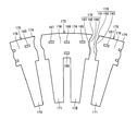
ここで、従来の形状を有する比較対象の分割ステータコアと比較して、本実施の形態の分割ステータコア175によって得られる効果について説明する。図8は、比較対象の分割ステータコア275の構成を示す平面図である。
Here, the effect obtained by the divided
比較対象の分割ステータコア275は、本実施の形態の分割ステータコア175と同様の構成を備えている。しかし、比較対象の分割ステータコア275は、ヨーク部276の周方向DR2の両端部に、突起部および窪み部が形成されておらず、径方向DR3に沿う平面形状の接合部278,279を有する。分割ステータコア275は、周方向DR2に隣接する他の分割ステータコアと、平面状の接合部278,279が接触することにより、接合される。
The divided
接合部278,279が径方向DR3に沿う平面形状を有するため、実施の形態1と異なり、分割ステータコア275には、隣接する他の分割ステータコアから径方向DR3の反力は作用しない。そのため、分割ステータコア275の外周側にリングを焼バメするときに、各々の分割ステータコア275にリングから均一に応力が作用しない場合、隣接する分割ステータコア275同士に径方向DR3の相対的な位置ずれが発生する。
Since the
図9は、本発明の分割ステータコア175と、比較対象の分割ステータコア275との真円度の比較を示すグラフである。図9に示すグラフの縦軸が真円度を示す。ここで真円度とは、円形形体の幾何学的に正しい円からの狂いの大きさをいう。円形形体とは、円形の形状や回転運動の軌跡のような機能上円であるべき部分をいう。真円度は、円形形体を二つの同心の幾何学的円で挟んだとき、同心円の半径方向の距離の差が最小となる場合の、この二つの同心円の半径方向の距離の差で表される。つまり、真円度が小さいほど、円形形体は幾何学的な円に近い形状となる。
FIG. 9 is a graph showing a comparison of roundness between the divided
上述したように、分割ステータコア175,275を外周側から筒状のリング181で焼バメ固定した際に、リング181から各分割ステータコア175,275に加わる応力が異なる。そのため、焼バメ後の分割ステータコア175,275の真円度が変化する。真円度を比較する場合に、リング181の内周側の面が完全に真円であると、真円度の差が出ないので、内径側の真円度を意図的に悪化させたリング181を使用して、図9に示す分割ステータコア175の内径側の面の真円度の比較を行なった。
As described above, when the divided
図9に示すように、比較対象の分割ステータコア275では、隣接する分割ステータコア275間に相対的な変位が生じるために、真円度が大きくなっている。すなわち、分割ステータコア275の真円からのずれが大きくなっている。これに対し、実施の形態1の分割ステータコア175では、隣接する分割ステータコア175同士の径方向DR3の変位が抑制されているために、真円度が小さくなり、より真円に近いように分割ステータコア175を配置することが可能となっている。このように、リング181の精度が悪くても、分割ステータコア175と隣接する他の分割ステータコア175との間に反力が働くことにより、ステータコア141の真円度を向上することができる。
As shown in FIG. 9, in the divided
図10は、周方向DR2に隣接する他の分割ステータコアから分割ステータコア175に作用する、周方向DR2の圧縮応力F3〜F8について示す図である。リング181をステータコア141の外周側に焼バメしたときに、リング181から径方向DR3内側方向へ応力が作用する。リング181からステータコア141全体に、ステータコア141の径を縮小するように応力が作用する。ステータコア141の径が小さくなることにより、隣接する分割ステータコア175間に、周方向DR2の圧縮応力が発生する。
FIG. 10 is a diagram illustrating compressive stresses F3 to F8 in the circumferential direction DR2 that act on the divided
分割ステータコア175は、隣接する他の分割ステータコアに対し、周方向DR2に対して傾斜した側壁部193cと側壁部196cとが面接触し、また側壁部193dと側壁部196dとが面接触する。分割ステータコア175と隣接する他の分割ステータコアとがテーパ面で当接し、側壁部193c,193d,196c,196dを介して周方向DR2の圧縮応力が分割ステータコア175から隣接する他の分割ステータコアに作用する。そのため、上述した周方向DR2の圧縮応力が分解され、径方向DR3の応力成分が発生する。
In the divided
分割ステータコア175の第二接合部179には、隣接する分割ステータコアの第一接合部178からの圧縮応力が作用する。第二接合部179には窪み部196が形成されており、径方向DR3に対して傾いた窪み部196の側壁部196c,196dに作用する周方向DR2の圧縮応力は、径方向DR3に分散する。つまり、窪み部196の最深部196bに対して外周側に位置する側壁部196cには、径方向DR3外側方向へ向いた応力F3が作用する。一方、最深部196bに対して内周側に位置する側壁部196dには、径方向DR3内側方向へ向いた応力F5が作用する。
Compressive stress from the
このように径方向DR3に応力を分散させることにより、分割ステータコア175へ作用する応力の周方向DR2の成分は低減される。周方向DR2に過大な圧縮応力が作用すると、分割ステータコア175を構成する電磁鋼板が折れ曲がって破壊する、すなわち電磁鋼板が座屈する可能性がある。図11は、分割ステータコア175を構成する電磁鋼板の座屈について説明するグラフである。図11に示すグラフの横軸は、分割ステータコア175へ作用する焼きバメ荷重を示し、縦軸は分割ステータコア175を構成する電磁鋼板の軸方向DR1の変形量を示す。
By dispersing the stress in the radial direction DR3 in this way, the component in the circumferential direction DR2 of the stress acting on the divided
図11に示すように、リング181を分割ステータコア175に焼バメするとき、リング181から分割ステータコア175へ作用する径方向DR3方向の荷重(焼きバメ荷重)が徐々に増大する。焼きバメ荷重が増大するに従って、周方向DR2において電磁鋼板に作用する圧縮応力も増大する。そして、ある荷重を超えると電磁鋼板が座屈し急激に電磁鋼板の軸方向の変形量が増大する。この電磁鋼板に座屈現象を引き起こす荷重のしきい値を、座屈荷重と称する。
As shown in FIG. 11, when the
リング181を焼バメすることにより、分割ステータコア175には、隣接する他の分割ステータコアから、周方向DR2の圧縮応力が作用する。この周方向DR2の圧縮応力が、分割ステータコア175を構成する電磁鋼板を座屈させる原因となる。本実施の形態では、分割ステータコア175に窪み部196を形成し径方向DR3に対し傾斜した面で圧縮応力を受けることにより、応力を径方向DR3にも分散させることが可能である。したがって、電磁鋼板の座屈荷重を向上させることができる。
By compressing the
また、図10に示すように、分割ステータコア175の第一接合部178には、隣接する他の分割ステータコアの第二接合部179からの圧縮応力が作用する。第一接合部178には突起部193が形成されており、径方向DR3に対して傾いた突起部193の側壁部193c,193dに作用する周方向DR2の圧縮応力は、径方向DR3に集中する。つまり、突起部193の先端部193aに対して外周側に位置する側壁部193cには、径方向DR3内側方向へ向いた応力F6が作用する。一方、先端部193aに対して内周側に位置する側壁部193dに対しては、径方向DR3外側方向へ向いた応力F8が作用する。
Further, as shown in FIG. 10, a compressive stress from the
このように、分割ステータコア175の第一接合部178付近では、隣接する分割ステータコア175から作用する周方向DR2の圧縮応力が集中する部分が発生する。しかしながら、本実施の形態の分割ステータコア175では、この応力集中部分にかしめ部187が形成され、応力が集中する箇所において電磁鋼板が軸方向DR1に固定される構造とされている。かしめ部187は、隣接する分割ステータコア175から第一接合部178側の周方向DR2端部が押圧されることによりヨーク部176の内部において圧縮応力が集中する部分に、形成されている。かしめ部187を形成することにより分割ステータコア175の強度が向上されているために、座屈荷重を向上することができる。
Thus, in the vicinity of the first
図12は、本発明の分割ステータコア175と、比較対象の分割ステータコア275との座屈荷重の比較を示すグラフである。図12に示すグラフの縦軸が座屈荷重を示す。上述したように、本実施の形態の分割ステータコア175では、第二接合部179に窪み部196が形成されていることにより径方向DR3に応力が分散され、また第一接合部178付近で応力が集中する箇所にかしめ部187が形成されていることにより、座屈荷重が向上しており、より座屈しにくくなっている。これに対し、図8に示す比較対象の分割ステータコア275の場合、応力を径方向に分散させる作用は発生せず、またかしめ部287によって圧縮応力に対する耐力を高め座屈荷重を向上させる効果は小さい。
FIG. 12 is a graph showing a comparison of buckling loads between the divided
これにより、図12に示すように、本発明の分割ステータコア175の座屈荷重は、比較対象の分割ステータコア275に比較して、より向上している。そのため、リング181から同一の径方向DR3内側方向への応力が作用した場合、この応力に対し比較対象の分割ステータコア275の方が、より座屈しやすくなっている。換言すると、本発明の分割ステータコア175では、リング181からより大きな応力を加えた場合でも、分割ステータコア175を構成する電磁鋼板が座屈することを抑制することができる。
Thereby, as shown in FIG. 12, the buckling load of the
突起部193および窪み部196が形成する略台形形状の寸法に関し、たとえば、径方向DR3における突起部193の先端部193aの長さと、側壁部193c,193dの長さとの比を、6:1にすることができる。つまり、図5に示すように、先端部193aの径方向長さをr3、根元部193bの径方向長さをr4としたとき、r3:(r4/2−r3/2)=6:1とすることができる。これを変形して、結局、r3:r4=3:4とすることができる。窪み部196の最深部196bの径方向長さr1と、開口部196aの径方向長さr2とについても、同様に、r1:r2=3:4とすることができる。
Regarding the dimension of the substantially trapezoidal shape formed by the
突起部193と窪み部196とが互いに突き当てられる部分の幅、すなわち、側壁部193c,193d,196c,196dの径方向DR3の長さの大小により、分割ステータコア175を構成する電磁鋼板の座屈応力は変動する。突起部193全体の径方向長さ(すなわち根元部193bの径方向長さr4)に対する先端部193aの径方向長さr3が大きすぎると、窪み部196の側壁部196c,196dに面接触する側壁部193c,193dからかしめ部187までの距離が大きくなるので、かしめ部187の拘束点としての機能が低下する。一方、先端部193aの径方向長さr3が小さすぎると、側壁部193c,193dの精度の安定性が低下する。
Buckling of the electrical steel sheet constituting the
これらを考慮して、先端部193aの径方向長さをr3と根元部193bの径方向長さをr4との比を3:4とし、同様に、最深部196bの径方向長さr1と開口部196aの径方向長さr2との比を3:4とすることができる。
Taking these into consideration, the ratio of the radial length of the
また、略台形形状の高さに相当する、周方向DR2における先端部193aと根元部193bとの間の距離は、根元部193bの径方向長さr4に対し3/16以上1/4以下の範囲で決定することができる。つまり、先端部193aと根元部193bとの間隔をhとすると、h:r3:r4=0.75〜1:3:4とすることができる。窪み部196の開口部196aと最深部196bとの間の周方向DR2の距離をdとすると、この距離dについても同様に、d:r1:r2=0.75〜1:3:4とすることができる。
The distance between the
略台形形状の高さが大きすぎると、隣接する分割ステータコア175を組み付けるときの精度が低下する。一方小さすぎると突起部193が窪み部196にうまく嵌合できない可能性がある。突起部193が窪み部196内に収容され、隣接する分割ステータコア175同士を精度よく接合できるために最適な略台形形状の高さとして、上述した距離hおよび距離dの値を決定することができる。このようにすれば、周方向DR2に隣接する分割ステータコア175を接合するときの組み付け性を確保することができる。
If the height of the substantially trapezoidal shape is too large, the accuracy when assembling the adjacent divided
上述した説明と一部重複する部分もあるが、本実施の形態の特徴的な構成を以下に列挙する。本実施の形態のステータコア141が備える複数の分割ステータコア175では、第二接合部179に窪み部196が形成されており、窪み部196は、最深部196bから開口部196aへ向かって開口面積が増加するように形成されている。このようにすれば、分割ステータコア175を組み付けるときに周方向DR2に圧入する必要なく、容易に複数の分割ステータコア175を環状に配置することができる。したがって、分割ステータコア175を容易に組み付けることができ、ステータコア141の組み付け性を向上することができる。
Although there is a part that overlaps with the above description, characteristic configurations of the present embodiment are listed below. In the plurality of divided
分割ステータコア175のヨーク部176には、突起部193の径方向長さr4の中央部を通り周方向DR2に延びる円弧上に、分割ステータコア175を軸方向DR1にかしめて鋼板を一体化する、かしめ部187が形成されている。このようにすれば、リング181が焼バメされて分割ステータコア175が固定されるとき、隣接する他の分割ステータコアから加わる圧縮応力が集中する部分に、かしめ部187が形成され、分割ステータコア175の強度が向上されている。そのため、分割ステータコア175を構成する電磁鋼板の座屈荷重を向上させることができるので、分割ステータコア175の剛性を向上させることができる。
The
分割ステータコア175の突起部193および窪み部196は、軸方向DR1に垂直な断面形状が略台形形状であるように形成されている。このようにすれば、窪み部196の開口面積を最深部196bから開口部196aへ向かって確実に増加させることができる。また、窪み部196に収容される突起部193は、先端部193aから根元部193bへ向かって、周方向DR2に垂直な断面積が徐々に増加するような形状に形成される。突起部193および窪み部196を、下底と斜辺とのなす角とが相等しい略台形形状に形成すれば、突起部193を窪み部196へ簡単に嵌め入れることができるので、容易に分割ステータコア175を組み付けることができる。
The projecting
突起部193を窪み部196に嵌合するとき、突起部193の側壁部193cと窪み部196の側壁部196cとが面接触し、突起部193の側壁部193dと窪み部196の側壁部196dとが面接触する。このようにすれば、周方向DR2に隣接する分割ステータコア175同士が相対的に径方向DR3に移動するのを抑制できる。したがって、分割ステータコア175の位置決め精度を向上することができ、ステータコア141の真円度を向上させることができる。かつ、隣接する分割ステータコア175から作用する周方向DR2の圧縮応力を径方向DR3に分散させ、応力の周方向DR2成分を低減することができる。したがって、分割ステータコア175を構成する電磁鋼板の座屈荷重を向上させることができる。
When the
かしめ部187は、ヨーク部176の第一接合部178近傍に形成されている。このようにすれば、隣接する他の分割ステータコアから周方向DR2の圧縮応力を受けた分割ステータコア175のヨーク部176の内部において、応力が集中する部分により近い箇所にかしめ部187を形成することができる。したがって、かしめ部187によって分割ステータコア175の剛性を向上させる効果を、より顕著に得ることができる。
The
周方向DR2におけるかしめ部187が形成される位置は、第一接合部178に近いほど応力集中部位に近いので望ましいが、近すぎると分割ステータコア175の製造時の誤差を許容できない。製造時の誤差を考慮しても確実にかしめ部187を形成できる程度に、周方向DR2に第一接合部178から離れる距離を最小とするように、かしめ部187の形成される位置が決定されるのが望ましい。
The position where the
たとえば、第一接合部178に近い側のステータティース171の、周方向DR2における中心部よりも第一接合部178に近接する位置に、かしめ部187を形成してもよい。分割ステータコア175を軸方向DR1に沿って平面視した場合に、突起部193の先端部193aに垂直な平面と、側壁部193cに垂直な平面と、側壁部193dに垂直な平面と、の重なる部分の少なくとも一部を含むように、かしめ部187を形成してもよい。
For example, the
なお同様に、かしめ部185を、第二接合部179に近い側のステータティース172の、周方向DR2における中心部よりも第二接合部179に近接する位置に、形成してもよい。第一接合部178の近傍面191および遠方面192を含む径方向DR3に延びる仮想的な平面とかしめ部187との周方向DR2における距離が、第二接合部179の近傍面197および遠方面195を含む径方向DR3に延びる仮想的な平面とかしめ部185との周方向DR2における距離に等しいように、かしめ部185,187を形成してもよい。
Similarly, the
分割ステータコア175は、ヨーク部176から径方向DR3内側に突出する二つのステータティース171,172を含む。円筒状のステータコア141において、周方向DR2に環状に配置される分割ステータコア175の部品数を少なくし、分割ステータコア175の周方向DR2の寸法を大きくするほど、座屈に対して有利である。
The divided
つまり、分割ステータコア175は製造上の公差を有する。各分割ステータコア175は、周方向DR2の寸法ばらつきを有する。周方向DR2における部品数が多いほど、公差が累積されて大きくなるので、ステータコア141の周方向DR2における寸法のばらつきが大きくなる。そのため、周方向DR2におけるステータコア141の寸法精度が低下し、リング181を使用して分割ステータコア175を組み付けた場合に、各分割ステータコア175が一体に固定されない可能性がある。したがって、一つの分割ステータコア175が二つのステータティース171,172を有するようにすれば、分割ステータコア175の周方向DR2寸法が大きくなるので、周方向DR2に配置される分割ステータコア175の部品数を低減できる。
That is, the
他方、分割ステータコア175のヨーク部176には曲率があり、ステータティース171,172は放射状に配置される。放射状のステータティース171,172に巻回されたコイルが、分割ステータコア175を円環状に組み付けるときに接触すると、分割ステータコア175を組み付けることが困難になる。そのため、一つの分割ステータコア175が有するステータティースの数は、二つが限度であると考えられる。このように、ステータコア141の寸法精度と、分割ステータコア175の組み付け上の要請とを考慮すると、二つのステータティース171,172を有する分割ステータコア175が最も好ましいと考えられる。
On the other hand, the
ヨーク部176には、周方向DR2における二つのステータティース171,172の中央に、分割ステータコア175を軸方向DR1にかしめるかしめ部186が形成されている。周方向DR2に沿って等間隔に形成されるステータティース171,172の間にかしめ部186を形成することにより、ヨーク部176の周方向DR2における中央部にかしめ部186を設けることができるので、分割ステータコア175の座屈に対する強度を向上することができる。周方向DR2における二つのステータティース171,172の間に複数のかしめ部(すなわちかしめ部186とかしめ部188)を形成することにより、分割ステータコア175の座屈を一層抑制することができる。
In the
ヨーク部176の第二接合部179近傍に、分割ステータコア175を軸方向DR1にかしめるかしめ部185が形成されており、周方向DR2におけるかしめ部187とかしめ部186との間隔は、周方向DR2におけるかしめ部186とかしめ部185との間隔に等しい。かしめ部187はヨーク部176の内部における応力集中部に形成され、かしめ部186は二つのステータティース171,172間に形成される。周方向DR2に沿ってかしめ部186からかしめ部187へ向く方向と反対方向において、二つのかしめ部186,187の周方向DR2における距離と等しい距離分周方向DR2にかしめ部186から離れた位置に、かしめ部185を形成する。このようにかしめ部185を形成することで、周方向DR2に隣接する他の分割ステータコアから加えられる圧縮応力に対し、分割ステータコア175の強度をさらに向上することができる。
A
かしめ部185は、開口部196aの径方向長さr2の中央部に形成されている。このようにかしめ部185を形成する位置が決定されることで、分割ステータコア175の強度をさらに向上することができる。
The
(実施の形態2)
図13は、実施の形態2の分割ステータコア175の構成を示す平面図である。図13に示す実施の形態2の分割ステータコア175は、上述した実施の形態1の分割ステータコアと比較して、突起部193の側壁部193c,193dおよび窪み部196の側壁部196c,196dの形状において異なっている。(Embodiment 2)
FIG. 13 is a plan view showing the configuration of the
具体的には、実施の形態1の突起部および窪み部の側壁部はいずれも平面状に形成されたのに対し、実施の形態2の突起部193の側壁部193c,193dは、先端部193aから根元部193bへ向かって湾曲する曲面形状である。同様に、窪み部196の側壁部196c,196dは、最深部196bから開口部196aへ向かって湾曲する曲面形状である。
Specifically, both the projections and the side walls of the recesses of the first embodiment are formed in a flat shape, whereas the
このように、曲面状の側壁部193c,193d,196c,196dを有する実施の形態2の分割ステータコア175においても、窪み部196は最深部196bから開口部196aへ向かって開口面積が増加するように形成されているために、分割ステータコア175の組み付けが容易である。また、突起部193の径方向長さの中央部にかしめ部187が形成されているために、分割ステータコア175の剛性が向上し、分割ステータコア175を構成する電磁鋼板の座屈を抑制することができる。
Thus, also in the
(実施の形態3)
図14は、実施の形態3の分割ステータコア175の構成を示す平面図である。図14に示す実施の形態3の分割ステータコア175は、突起部193および窪み部196が、平面形状円弧状に形成されている点で、上述した実施の形態1の分割ステータコアと異なっている。突起部193の先端部193a、および窪み部196の最深部196bは、実施の形態1,2と異なり、平面形状に形成されておらず、軸方向DR1に延びる線状の形状を有する。(Embodiment 3)
FIG. 14 is a plan view showing the configuration of the
このように円弧状の突起部193および窪み部196を有する実施の形態3の分割ステータコア175においても、窪み部196は最深部196bから開口部196aへ向かって開口面積が増加するように形成されているために、分割ステータコア175の組み付けが容易である。また、突起部193の径方向長さの中央部にかしめ部187が形成されているために、分割ステータコア175の剛性が向上し、分割ステータコア175を構成する電磁鋼板の座屈を抑制することができる。
Thus, also in the
以上のように本発明の実施の形態について説明を行なったが、今回開示された実施の形態はすべての点で例示であって、制限的なものではないと考えられるべきである。この発明の範囲は上記した説明ではなくて請求の範囲によって示され、請求の範囲と均等の意味、および範囲内でのすべての変更が含まれることが意図される。 Although the embodiment of the present invention has been described as above, the embodiment disclosed this time should be considered as illustrative in all points and not restrictive. The scope of the present invention is defined by the terms of the claims, rather than the description above, and is intended to include any modifications within the scope and meaning equivalent to the terms of the claims.
140 ステータ、141 ステータコア、171,172 ステータティース、174 外周面、175,175a,175b 分割ステータコア、176 ヨーク部、178 第一接合部、179 第二接合部、181 リング、185,186,187,188 かしめ部、191,197 近傍面、192,195 遠方面、193 突起部、193a 先端部、193b 根元部、193c,193d,196c,196d 側壁部、196 窪み部、196a 開口部、196b 最深部、DR1 軸方向、DR2 周方向、DR3 径方向。 140 Stator, 141 Stator core, 171, 172 Stator teeth, 174 Outer surface, 175, 175a, 175b Split stator core, 176 Yoke part, 178 First joint part, 179 Second joint part, 181 Ring, 185, 186, 187, 188 Caulking portion, 191 and 197 near surface, 192 and 195 far surface, 193 protrusion, 193a tip portion, 193b root portion, 193c, 193d, 196c, and 196d side wall portion, 196 recess portion, 196a opening portion, 196b deepest portion, DR1 Axial direction, DR2 circumferential direction, DR3 radial direction.
Claims (5)
前記分割ステータコア(175)は、周方向(DR2)に延在するヨーク部(176)と、前記ヨーク部(176)から径方向(DR3)内側に突出する二つのティース部(171,172)とを含み、
前記ヨーク部(176)は、前記周方向(DR2)の一端に設けられた第一接合部(178)と、前記周方向(DR2)の他端に設けられた第二接合部(179)とを有し、
前記第一接合部(178)と前記第二接合部(179)とは、前記分割ステータコア(175)が環状に配置されたときに前記分割ステータコア(175)と隣接する他の分割ステータコアとを接合し、
前記第一接合部(178)には、前記隣接する他の分割ステータコアに向かって突起する突起部(193)が形成されており、
前記突起部(193)は、前記軸方向(DR1)に垂直な断面形状が略台形形状であり、前記径方向(DR3)における前記突起部(193)の先端部(193a)の長さ(r3)と根元部(193b)の長さ(r4)との比を3:4とするように形成されており、
前記第二接合部(179)には、前記突起部(193)を収容可能な窪み部(196)が形成されており、
前記窪み部(196)は、前記軸方向(DR1)に垂直な断面形状が略台形形状であり、前記窪み部(196)の最深部(196b)から前記窪み部(196)の開口部(196a)へ向かって開口面積が増加し、前記径方向(DR3)における前記窪み部(196)の最深部(196b)の長さ(r1)と開口部(196a)の長さ(r2)との比を3:4とするように形成されており、
前記突起部(193)を前記窪み部(196)に嵌合するとき、前記突起部(193)の略台形形状の斜辺(193c,193d)と前記窪み部(196)の略台形形状の斜辺(196c,196d)とが面接触し、
前記ヨーク部(176)の、前記二つのティース部(171,172)のうち前記第一接合部(178)に近い側のティース部(171)の前記周方向(DR2)における中心部よりも第一接合部(178)に近接する位置であって、前記一端が前記周方向(DR2)に押圧されることによる応力が集中する部分に、前記分割ステータコア(175)を前記軸方向(DR1)にかしめて前記鋼板を一体化する、第一のかしめ部(187)が形成されている、ステータコア(141)。A plurality of divided stator cores (175) arranged in an annular shape, each including a divided stator core (175) formed by laminating a plurality of steel plates in the axial direction (DR1);
The split stator core (175) includes a yoke portion (176) extending in the circumferential direction (DR2), and two teeth portions (171, 172) protruding inward in the radial direction (DR3) from the yoke portion (176). Including
The yoke portion (176) includes a first joint portion (178) provided at one end in the circumferential direction (DR2) and a second joint portion (179) provided at the other end in the circumferential direction (DR2). Have
The first joint portion (178) and the second joint portion (179) join the split stator core (175) and another adjacent split stator core when the split stator core (175) is annularly arranged. And
The first joint (178) is formed with a protrusion (193) that protrudes toward the other adjacent divided stator core,
The protrusion (193) has a substantially trapezoidal cross-sectional shape perpendicular to the axial direction (DR1), and the length (r3) of the tip (193a) of the protrusion (193) in the radial direction (DR3). ) And the length (r4) of the root portion (193b) is formed to be 3: 4,
The second joint (179) is formed with a recess (196) that can accommodate the protrusion (193).
The depression (196) has a substantially trapezoidal cross-sectional shape perpendicular to the axial direction (DR1), and the opening (196a) from the deepest part (196b) of the depression (196). ) And the ratio of the length (r1) of the deepest part (196b) of the recess (196) to the length (r2) of the opening (196a) in the radial direction (DR3). Is formed to be 3: 4,
When the protrusion (193) is fitted into the recess (196), the substantially trapezoidal hypotenuse (193c, 193d) of the projection (193) and the approximate trapezoidal hypotenuse of the recess (196) ( 196c, 196d) are in surface contact,
The yoke portion (176) has a tooth portion (171) closer to the first joint portion (178) of the two teeth portions (171, 172) than the center portion in the circumferential direction (DR2). The split stator core (175) is placed in the axial direction (DR1) at a position close to one joint (178) where stress is concentrated by pressing the one end in the circumferential direction (DR2). A stator core (141) in which a first caulking portion (187) for caulking and integrating the steel plates is formed.
前記周方向(DR2)における前記第一のかしめ部(187)と前記第二のかしめ部(186)との間隔は、前記周方向(DR2)における前記第二のかしめ部(186)と前記第三のかしめ部(185)との間隔に等しい、請求項2に記載のステータコア(141)。A third caulking portion (185) for caulking the split stator core (175) in the axial direction (DR1) is formed in the vicinity of the second joint portion (179) of the yoke portion (176).
The distance between the first caulking portion (187) and the second caulking portion (186) in the circumferential direction (DR2) is the same as the distance between the second caulking portion (186) and the second caulking portion (186) in the circumferential direction (DR2). The stator core (141) according to claim 2, wherein the stator core (141) is equal to the distance from the third crimp (185).
前記窪み部(196)の前記開口部(196a)と前記最深部(196b)との間の前記周方向(DR2)の距離(d)と、前記最深部(196b)の前記径方向(DR3)の長さ(r1)と、前記開口部(196a)の前記径方向(DR3)の長さ(r2)との比を、0.75〜1:3:4とする、請求項1から請求項4のいずれかに記載のステータコア(141)。The distance (h) in the circumferential direction (DR2) between the tip (193a) and the root (193b) of the protrusion (193) and the radial direction (DR3) of the tip (193a). The ratio of the length (r3) of the base portion (193b) to the length (r4) in the radial direction (DR3) is 0.75 to 1: 3: 4,
The distance (d) in the circumferential direction (DR2) between the opening (196a) and the deepest portion (196b) of the recess (196), and the radial direction (DR3) of the deepest portion (196b). The ratio between the length (r1) of the opening and the length (r2) of the opening (196a) in the radial direction (DR3) is 0.75 to 1: 3: 4. 4. The stator core (141) according to claim 4.
Applications Claiming Priority (1)
| Application Number | Priority Date | Filing Date | Title |
|---|---|---|---|
| PCT/JP2010/051474 WO2011096050A1 (en) | 2010-02-03 | 2010-02-03 | Stator core |
Publications (2)
| Publication Number | Publication Date |
|---|---|
| JPWO2011096050A1 JPWO2011096050A1 (en) | 2013-06-06 |
| JP5387698B2 true JP5387698B2 (en) | 2014-01-15 |
Family
ID=44355079
Family Applications (1)
| Application Number | Title | Priority Date | Filing Date |
|---|---|---|---|
| JP2011552605A Active JP5387698B2 (en) | 2010-02-03 | 2010-02-03 | Stator core |
Country Status (5)
| Country | Link |
|---|---|
| US (1) | US8853914B2 (en) |
| EP (1) | EP2523309B1 (en) |
| JP (1) | JP5387698B2 (en) |
| CN (1) | CN102742125B (en) |
| WO (1) | WO2011096050A1 (en) |
Families Citing this family (9)
| Publication number | Priority date | Publication date | Assignee | Title |
|---|---|---|---|---|
| JP5519550B2 (en) * | 2011-02-15 | 2014-06-11 | トヨタ自動車株式会社 | Split core and stator core |
| DE102012019182A1 (en) | 2012-09-28 | 2013-03-21 | Daimler Ag | Connection assembly of ring segments of rotor for electric machine e.g. motor used in passenger car, has plastic deformation portions that are provided in rotor, for mutually coupling ring segments in axial direction of rotor |
| CN106402770A (en) * | 2016-08-29 | 2017-02-15 | 嘉兴海拉灯具有限公司 | Headlight and vehicle provided with same |
| DE102017200186A1 (en) | 2017-01-09 | 2018-07-12 | Siemens Aktiengesellschaft | Rotor plate for a permanent-magnet electric motor and rotor |
| CN107124050B (en) * | 2017-06-28 | 2024-02-13 | 安徽美芝制冷设备有限公司 | Stator punching sheet, motor and compressor |
| CN111602317B (en) * | 2018-01-24 | 2022-05-24 | 三菱电机株式会社 | Stator and motor |
| JPWO2019175930A1 (en) * | 2018-03-12 | 2020-12-17 | 三菱電機株式会社 | Motor stator and motor |
| JP6640910B2 (en) * | 2018-05-15 | 2020-02-05 | 三菱電機株式会社 | Rotating electric machine |
| WO2020168137A1 (en) * | 2019-02-13 | 2020-08-20 | Linear Labs, Inc. | A method of manufacturing a three-dimensional flux structure for circumferential flux machines |
Citations (5)
| Publication number | Priority date | Publication date | Assignee | Title |
|---|---|---|---|---|
| JP2001045684A (en) * | 1999-07-30 | 2001-02-16 | Hitachi Ltd | Manufacturing method of electric motor stator core |
| JP2002199628A (en) * | 2000-12-28 | 2002-07-12 | Aisin Aw Co Ltd | Divided core sheet member for rotating electric machine, core having the divided core sheet member and manufacturing method of core having divided core sheet member |
| JP2003264944A (en) * | 2002-03-07 | 2003-09-19 | Toyota Motor Corp | Motor stator core assembly and stator assembly method |
| JP2004289908A (en) * | 2003-03-20 | 2004-10-14 | Mitsui High Tec Inc | Manufacturing method for layered iron core |
| WO2006120975A1 (en) * | 2005-05-06 | 2006-11-16 | Mitsuba Corporation | Motor, rotary electric machine and its stator, and method for manufacturing the stator |
Family Cites Families (12)
| Publication number | Priority date | Publication date | Assignee | Title |
|---|---|---|---|---|
| JP3306649B2 (en) | 1997-04-02 | 2002-07-24 | 本田技研工業株式会社 | Stator core |
| TWI259638B (en) * | 2004-12-01 | 2006-08-01 | Ind Tech Res Inst | Structure of an electric motor |
| JP4286829B2 (en) | 2005-03-24 | 2009-07-01 | 株式会社一宮電機 | Manufacturing method of rotating machine |
| JP2006340509A (en) | 2005-06-02 | 2006-12-14 | Mitsuba Corp | Stator for electric motor and electric motor |
| JP4579775B2 (en) | 2005-06-15 | 2010-11-10 | 東芝産業機器製造株式会社 | Stator core and stator for rotating electrical machine |
| JP2007129835A (en) | 2005-11-04 | 2007-05-24 | Aisin Seiki Co Ltd | Motor |
| JP2008206262A (en) | 2007-02-19 | 2008-09-04 | Mitsui High Tec Inc | Laminated core, and manufacturing method therefor |
| JP5039473B2 (en) * | 2007-04-27 | 2012-10-03 | 株式会社三井ハイテック | Method and apparatus for manufacturing split laminated iron core |
| JP5126577B2 (en) | 2007-06-27 | 2013-01-23 | 株式会社デンソー | Rotating electric machine stator |
| JP5256778B2 (en) * | 2008-02-28 | 2013-08-07 | 日本電産株式会社 | Motor rotor and motor |
| JP5233417B2 (en) * | 2008-05-29 | 2013-07-10 | トヨタ自動車株式会社 | Rotating electric machine |
| JP5151738B2 (en) * | 2008-07-01 | 2013-02-27 | 株式会社デンソー | Rotating electric machine stator and rotating electric machine |
-
2010
- 2010-02-03 US US13/510,189 patent/US8853914B2/en active Active
- 2010-02-03 EP EP10845187.3A patent/EP2523309B1/en active Active
- 2010-02-03 JP JP2011552605A patent/JP5387698B2/en active Active
- 2010-02-03 CN CN201080063127.8A patent/CN102742125B/en not_active Expired - Fee Related
- 2010-02-03 WO PCT/JP2010/051474 patent/WO2011096050A1/en active Application Filing
Patent Citations (5)
| Publication number | Priority date | Publication date | Assignee | Title |
|---|---|---|---|---|
| JP2001045684A (en) * | 1999-07-30 | 2001-02-16 | Hitachi Ltd | Manufacturing method of electric motor stator core |
| JP2002199628A (en) * | 2000-12-28 | 2002-07-12 | Aisin Aw Co Ltd | Divided core sheet member for rotating electric machine, core having the divided core sheet member and manufacturing method of core having divided core sheet member |
| JP2003264944A (en) * | 2002-03-07 | 2003-09-19 | Toyota Motor Corp | Motor stator core assembly and stator assembly method |
| JP2004289908A (en) * | 2003-03-20 | 2004-10-14 | Mitsui High Tec Inc | Manufacturing method for layered iron core |
| WO2006120975A1 (en) * | 2005-05-06 | 2006-11-16 | Mitsuba Corporation | Motor, rotary electric machine and its stator, and method for manufacturing the stator |
Also Published As
| Publication number | Publication date |
|---|---|
| WO2011096050A1 (en) | 2011-08-11 |
| EP2523309B1 (en) | 2019-09-04 |
| US20120228987A1 (en) | 2012-09-13 |
| JPWO2011096050A1 (en) | 2013-06-06 |
| EP2523309A1 (en) | 2012-11-14 |
| CN102742125B (en) | 2015-06-10 |
| EP2523309A4 (en) | 2017-06-14 |
| US8853914B2 (en) | 2014-10-07 |
| CN102742125A (en) | 2012-10-17 |
Similar Documents
| Publication | Publication Date | Title |
|---|---|---|
| JP5387698B2 (en) | Stator core | |
| US7948133B2 (en) | Rotor and rotating electric machine with the rotor | |
| JP4842670B2 (en) | Rotor and electric vehicle | |
| JP5601799B2 (en) | Stator and stator manufacturing method | |
| US10186916B2 (en) | Rotary machine and electric vehicle | |
| WO2008047942A1 (en) | Stator core and rotating electrical machine | |
| JP5396842B2 (en) | Rotating electric machine and method of manufacturing rotating electric machine | |
| US20040155550A1 (en) | Armature having teeth | |
| JP2010068569A (en) | Stator | |
| CN113016125A (en) | Rotor, motor, and method for manufacturing rotor | |
| JP5460370B2 (en) | Stator split core | |
| JP6498536B2 (en) | Core and rotating electrical machine | |
| US9130420B2 (en) | Stator having a plurality of stator core segments and rotating electric machine including same | |
| JP2012130205A (en) | Core of rotary electric machine and manufacturing method of the same | |
| JP2008187864A (en) | Stator support structure | |
| JP4962280B2 (en) | Rotating electric machine | |
| JP2009106004A (en) | Rotating electric machine | |
| CN110323878B (en) | Electric motor | |
| KR20160051580A (en) | Permanent magnet motor | |
| JP7254675B2 (en) | Brushless motor and stator manufacturing method | |
| CN112425045A (en) | Electric machine | |
| JP2009219192A (en) | Armature core of motor | |
| KR20220076805A (en) | Motor | |
| JP2011259661A (en) | Stator core | |
| WO2024194959A1 (en) | Motor |
Legal Events
| Date | Code | Title | Description |
|---|---|---|---|
| TRDD | Decision of grant or rejection written | ||
| A01 | Written decision to grant a patent or to grant a registration (utility model) |
Free format text: JAPANESE INTERMEDIATE CODE: A01 Effective date: 20130910 |
|
| A61 | First payment of annual fees (during grant procedure) |
Free format text: JAPANESE INTERMEDIATE CODE: A61 Effective date: 20130923 |
|
| R151 | Written notification of patent or utility model registration |
Ref document number: 5387698 Country of ref document: JP Free format text: JAPANESE INTERMEDIATE CODE: R151 |