JP5359680B2 - Fuel shut-off valve - Google Patents
Fuel shut-off valve Download PDFInfo
- Publication number
- JP5359680B2 JP5359680B2 JP2009190132A JP2009190132A JP5359680B2 JP 5359680 B2 JP5359680 B2 JP 5359680B2 JP 2009190132 A JP2009190132 A JP 2009190132A JP 2009190132 A JP2009190132 A JP 2009190132A JP 5359680 B2 JP5359680 B2 JP 5359680B2
- Authority
- JP
- Japan
- Prior art keywords
- float
- arm
- fuel
- arm portion
- absorbing member
- Prior art date
- Legal status (The legal status is an assumption and is not a legal conclusion. Google has not performed a legal analysis and makes no representation as to the accuracy of the status listed.)
- Expired - Fee Related
Links
Images


Classifications
-
- F—MECHANICAL ENGINEERING; LIGHTING; HEATING; WEAPONS; BLASTING
- F16—ENGINEERING ELEMENTS AND UNITS; GENERAL MEASURES FOR PRODUCING AND MAINTAINING EFFECTIVE FUNCTIONING OF MACHINES OR INSTALLATIONS; THERMAL INSULATION IN GENERAL
- F16K—VALVES; TAPS; COCKS; ACTUATING-FLOATS; DEVICES FOR VENTING OR AERATING
- F16K24/00—Devices, e.g. valves, for venting or aerating enclosures
- F16K24/04—Devices, e.g. valves, for venting or aerating enclosures for venting only
- F16K24/042—Devices, e.g. valves, for venting or aerating enclosures for venting only actuated by a float
- F16K24/044—Devices, e.g. valves, for venting or aerating enclosures for venting only actuated by a float the float being rigidly connected to the valve element, the assembly of float and valve element following a substantially translational movement when actuated, e.g. also for actuating a pilot valve
-
- B—PERFORMING OPERATIONS; TRANSPORTING
- B60—VEHICLES IN GENERAL
- B60K—ARRANGEMENT OR MOUNTING OF PROPULSION UNITS OR OF TRANSMISSIONS IN VEHICLES; ARRANGEMENT OR MOUNTING OF PLURAL DIVERSE PRIME-MOVERS IN VEHICLES; AUXILIARY DRIVES FOR VEHICLES; INSTRUMENTATION OR DASHBOARDS FOR VEHICLES; ARRANGEMENTS IN CONNECTION WITH COOLING, AIR INTAKE, GAS EXHAUST OR FUEL SUPPLY OF PROPULSION UNITS IN VEHICLES
- B60K15/00—Arrangement in connection with fuel supply of combustion engines or other fuel consuming energy converters, e.g. fuel cells; Mounting or construction of fuel tanks
- B60K15/03—Fuel tanks
- B60K15/035—Fuel tanks characterised by venting means
- B60K15/03519—Valve arrangements in the vent line
-
- Y—GENERAL TAGGING OF NEW TECHNOLOGICAL DEVELOPMENTS; GENERAL TAGGING OF CROSS-SECTIONAL TECHNOLOGIES SPANNING OVER SEVERAL SECTIONS OF THE IPC; TECHNICAL SUBJECTS COVERED BY FORMER USPC CROSS-REFERENCE ART COLLECTIONS [XRACs] AND DIGESTS
- Y10—TECHNICAL SUBJECTS COVERED BY FORMER USPC
- Y10T—TECHNICAL SUBJECTS COVERED BY FORMER US CLASSIFICATION
- Y10T137/00—Fluid handling
- Y10T137/0753—Control by change of position or inertia of system
- Y10T137/0874—Vent opening or closing on tipping container
-
- Y—GENERAL TAGGING OF NEW TECHNOLOGICAL DEVELOPMENTS; GENERAL TAGGING OF CROSS-SECTIONAL TECHNOLOGIES SPANNING OVER SEVERAL SECTIONS OF THE IPC; TECHNICAL SUBJECTS COVERED BY FORMER USPC CROSS-REFERENCE ART COLLECTIONS [XRACs] AND DIGESTS
- Y10—TECHNICAL SUBJECTS COVERED BY FORMER USPC
- Y10T—TECHNICAL SUBJECTS COVERED BY FORMER US CLASSIFICATION
- Y10T137/00—Fluid handling
- Y10T137/2931—Diverse fluid containing pressure systems
- Y10T137/3003—Fluid separating traps or vents
- Y10T137/3084—Discriminating outlet for gas
- Y10T137/309—Fluid sensing valve
- Y10T137/3099—Float responsive
-
- Y—GENERAL TAGGING OF NEW TECHNOLOGICAL DEVELOPMENTS; GENERAL TAGGING OF CROSS-SECTIONAL TECHNOLOGIES SPANNING OVER SEVERAL SECTIONS OF THE IPC; TECHNICAL SUBJECTS COVERED BY FORMER USPC CROSS-REFERENCE ART COLLECTIONS [XRACs] AND DIGESTS
- Y10—TECHNICAL SUBJECTS COVERED BY FORMER USPC
- Y10T—TECHNICAL SUBJECTS COVERED BY FORMER US CLASSIFICATION
- Y10T137/00—Fluid handling
- Y10T137/7287—Liquid level responsive or maintaining systems
- Y10T137/7358—By float controlled valve
- Y10T137/7423—Rectilinearly traveling float
- Y10T137/7426—Float co-axial with valve or port
Landscapes
- Engineering & Computer Science (AREA)
- General Engineering & Computer Science (AREA)
- Mechanical Engineering (AREA)
- Cooling, Air Intake And Gas Exhaust, And Fuel Tank Arrangements In Propulsion Units (AREA)
- Float Valves (AREA)
Description
本発明は、車両の燃料タンクに取り付けられる燃料遮断弁に関する。 The present invention relates to a fuel cutoff valve attached to a fuel tank of a vehicle.
燃料タンク内には、燃料が蒸発して発生するガスを排気するとともに、排気口から燃料が流出するのを遮断する燃料遮断弁が設けられている。例えば、図10に示すように、燃料遮断弁9は、燃料タンク91の上部に取り付けられ、燃料満タン検知器等に接続される接続通路92を上部に設けたケーシング93と、ケーシング93の弁室に流入した燃料の液位Lの昇降によって浮力を増減することで昇降するフロート94とを有する。フロート94の上部には、接続通路92を形成する上筒部95が配置されている。フロート94は、フロート94が昇降することで上筒部95の下端に形成されたシール部96に離接する。弁室内の燃料液位が上昇してフロート94が上昇すると、フロート94の上壁がシール部96に接して、接続通路92を閉止する。図11に示すように、弁室内の燃料液位が下降してフロート94が下降すると、フロート94の上壁がシール部96から離れて、接続通路92を開く。フロート94の側壁には、爪部97が突出しており、爪部97は、ケーシング93の側壁に開口するガイド穴98に昇降自在に係止されている。爪部97がガイド穴98にガイドされながら昇降する。爪部97が穴部98の下端98aに当接することで、フロート94の下降が規制される。
In the fuel tank, there is provided a fuel shut-off valve that exhausts the gas generated by the evaporation of the fuel and blocks the fuel from flowing out from the exhaust port. For example, as shown in FIG. 10, the
ところで、フロート94が上昇してケーシング93のシール部96に当接するとき、及びフロート94が下降してケーシング93のガイド穴98の下端98aに当接するときには、衝撃音が発生する。この衝撃音は、車室内に聞こえることがある。
By the way, when the
そこで、従来、フロートがケーシングに当接するときに発生する衝撃音を低減するために、特許文献1,2に開示されているように、ケーシングの底部にゴム台座や弾性アームを設けていた。
Therefore, conventionally, in order to reduce the impact sound generated when the float comes into contact with the casing, as disclosed in
しかしながら、特許文献1,2では、フロート下降時に発生する衝撃音の低減をしているにすぎず、フロート上昇時の衝撃音を低減するものではない。また、ケーシングにゴム台座や弾性アームを設置するには、ケーシングに床板を設ける必要がある。このため、燃料遮断弁の構造が複雑なものとなる。
However,
本発明はかかる事情に鑑みてなされたものであり、フロートが上昇下降の際に発生する衝撃音を低減することができる燃料遮断弁を提供することを課題とする。 This invention is made | formed in view of this situation, and makes it a subject to provide the fuel cutoff valve which can reduce the impact sound which generate | occur | produces when a float raises / lowers.
(1)第1の発明は、燃料タンクの上部に装着され、該燃料タンクの内部と外部とを接続する接続通路を開閉することで前記燃料タンクの内部と外部とを連通遮断する燃料遮断弁において、前記接続通路と前記燃料タンクの内部とを連通する弁室と、該弁室を形成するケース本体部、該ケース本体部の上側に配置され前記弁室に突出して前記接続通路を形成する筒部、及び該筒部の下部に設けられたシール部、を有するケーシングと,前記弁室に収容され前記弁室内の燃料液位により浮力を増減して昇降するフロートと、前記シール部と前記フロートとの間に配置され、少なくとも前記フロートが下降するときに該フロートに係合する係合部及び前記シール部に離接するシート部をもち、前記フロートとともに前記弁室を昇降して前記シート部が前記シール部に離接することで前記接続通路を開閉する衝撃吸収部材と、を備え、該衝撃吸収部材は、前記シート部を径方向の中心部に配置しているとともに該シート部から径方向外側に前記係合部を設けており、前記シート部の径方向外側に突設され弾性を有する第1アーム部、前記第1アーム部又は前記シート部から突設されて先端が自由端であり弾性を有する第2アーム部、前記第2アーム部の前記先端に設けられ上昇する前記フロートに当接する当接部、及び前記第1アーム部の径方向外側の先端に設けられ前記弁室で最下位に位置するときに前記ケース本体部に係止される係止部、を有することを特徴とする(請求項1)。 (1) A first aspect of the invention is a fuel cutoff valve that is mounted on an upper portion of a fuel tank, and that opens and closes a connection passage that connects the inside and outside of the fuel tank so as to cut off communication between the inside and outside of the fuel tank. A valve chamber communicating with the connection passage and the inside of the fuel tank, a case main body forming the valve chamber, and disposed above the case main body to project into the valve chamber to form the connection passage. A casing having a cylindrical portion and a seal portion provided at a lower portion of the cylindrical portion; a float that is accommodated in the valve chamber and moves up and down by increasing or decreasing buoyancy according to a fuel liquid level in the valve chamber; and the seal portion and the The seat is arranged between the float and has at least an engaging portion that engages with the float when the float descends and a seat portion that is separated from and contacting the seal portion, and moves up and down the valve chamber together with the float. And an impact absorbing member that opens and closes the connecting passage by being separated from and coming into contact with the seal portion, and the impact absorbing member has the seat portion arranged in a central portion in the radial direction and the radial direction from the seat portion. The engaging portion is provided on the outer side, and protrudes from the outer side in the radial direction of the seat portion and has elasticity, and protrudes from the first arm portion, the first arm portion, or the seat portion, and the tip is a free end. A second arm portion having elasticity, a contact portion provided at the tip of the second arm portion and in contact with the rising float, and provided at the tip of the first arm portion on the radially outer side in the valve chamber. It has a latching | locking part latched by the said case main-body part when it is located in the low order (Claim 1).
上記構成によれば、燃料遮断弁は、燃料タンク内の燃料液位よりも上側に取り付けられる。燃料の揺動、給油などの原因により燃料遮断弁内の弁室の燃料液位が上昇すると、フロートは、浮力が増加して上昇する。フロートは、衝撃吸収部材の当接部に当接しながら衝撃吸収部材とともに上昇する。やがて、衝撃吸収部材のシート部が、ケーシングのシール部に当接して、接続通路を閉止する。 According to the said structure, a fuel cutoff valve is attached above the fuel liquid level in a fuel tank. When the fuel level in the valve chamber in the fuel shutoff valve rises due to fuel oscillation, fuel supply, etc., the float rises with increased buoyancy. The float rises together with the impact absorbing member while abutting against the abutting portion of the impact absorbing member. Eventually, the seat portion of the impact absorbing member comes into contact with the seal portion of the casing and closes the connection passage.
ここで、当接部とシート部との間には、弾性をもつ第2アーム部が設けられている。このため、シート部がシール部に当接すると、第2アーム部が弾性変形して、当接時の衝撃が吸収される。ゆえに、シート部がシール部に当接するときに発生する衝撃音が軽減される。 Here, an elastic second arm portion is provided between the contact portion and the seat portion. For this reason, when the seat portion comes into contact with the seal portion, the second arm portion is elastically deformed and the impact at the time of contact is absorbed. Therefore, the impact sound generated when the seat portion comes into contact with the seal portion is reduced.
次に、燃料の揺動、燃料消費などの原因により弁室の燃料液位が下降すると、フロートは、浮力が減少して下降する。これにより、シート部は、シール部から離間して接続通路を開放する。また、フロートは、係合部で、衝撃吸収部材に係合しながら衝撃吸収部材とともに弁室内を下降する。やがて、衝撃吸収部材が、弁室で最下位に位置したとき、衝撃吸収部材に設けられた係止部が、ケ−シングのケース本体部に当接する。係止部は、第1アーム部の先端に設けられているため、ケース本体部に当接するときに、第1アーム部が弾性変形して、当接時の衝撃が吸収される。ゆえに、係止部がケース本体部に係止するときに発生する衝撃音が軽減される。 Next, when the fuel level in the valve chamber is lowered due to fuel oscillation, fuel consumption, or the like, the float is lowered due to a decrease in buoyancy. Accordingly, the seat portion is separated from the seal portion and opens the connection passage. The float is lowered at the engagement portion together with the impact absorbing member while being engaged with the impact absorbing member. Eventually, when the shock absorbing member is positioned at the lowest position in the valve chamber, the engaging portion provided in the shock absorbing member comes into contact with the case body of the casing. Since the locking portion is provided at the tip of the first arm portion, the first arm portion is elastically deformed when coming into contact with the case main body portion, and the impact at the time of contact is absorbed. Therefore, the impact sound generated when the locking portion is locked to the case main body is reduced.
以上のように、第1の発明によれば、フロートの上昇時及び下降時の双方でケーシングに当接するときに発生する衝撃音を軽減することができる。 As described above, according to the first aspect, it is possible to reduce the impact sound that is generated when the float comes into contact with the casing both when the float is raised and when it is lowered.
(2)前記衝撃吸収部材に形成された上壁は、該上壁の上面に設けられた前記シート部、該上壁の下面に突設された前記当接部、前記フロート上昇時に前記フロートが前記当接部に当接したときに上方に弾性変形する前記第2アーム部、及び前記フロート下降時に前記係止部が前記ケース本体部に係止されたときに下方に弾性変形する前記第1アーム部をもつことが好ましい(請求項2)。 (2) The upper wall formed on the impact absorbing member includes the seat portion provided on the upper surface of the upper wall, the contact portion projecting on the lower surface of the upper wall, and the float when the float is raised. The second arm part that elastically deforms upward when contacting the contact part, and the first arm that elastically deforms downward when the locking part is locked to the case body when the float is lowered. It is preferable to have an arm part (Claim 2).
この場合には、フロート上昇時にフロートが当接部に当接したときに、第2アーム部が上方に弾性変形する。フロート下降時に係止部がケース本体部に係止されたときに、第1アーム部が下方に弾性変形する。このため、フロートの昇降時に生じる衝撃音を軽減することができる。 In this case, when the float comes into contact with the contact portion when the float is raised, the second arm portion is elastically deformed upward. When the locking portion is locked to the case body when the float is lowered, the first arm portion is elastically deformed downward. For this reason, it is possible to reduce the impact sound generated when the float is raised and lowered.
(3)前記第1アーム部は、先端に前記係止部をもち、前記ケース本体部に形成された側壁は、前記係止部の昇降をガイドするガイド穴をもち、前記係止部は、前記衝撃吸収部材が前記弁室で最下位に位置するときに前記ガイド穴の下端に係止されることが好ましい(請求項3)。 (3) The first arm portion has the locking portion at a tip, the side wall formed in the case main body portion has a guide hole for guiding the lifting and lowering of the locking portion, and the locking portion is When the impact absorbing member is positioned at the lowest position in the valve chamber, it is preferable that the impact absorbing member is locked to the lower end of the guide hole.
この場合には、衝撃吸収部材の係止部が、ケーシングに設けられたガイド穴にガイドされながら昇降する。ゆえに、衝撃吸収部材を弁室の正確な位置に維持することができる。 In this case, the locking portion of the shock absorbing member moves up and down while being guided by a guide hole provided in the casing. Therefore, the shock absorbing member can be maintained at an accurate position of the valve chamber.
(4)前記第1アーム部は前記シート部の径方向外側に枠状に突設され、前記第2アーム部はスリットを介して前記第1アーム部に囲まれていることが好ましい(請求項7)。この場合には、第1アーム部と第2アーム部とが別々のタイミングで撓むことができる。即ち、フロート上昇時に当接部がフロートに当接して第2アーム部が撓みやすくなり、また、フロート下降時に係合部がフロートに係合されることで、第1アーム部が撓みやすくなる。また、第1アーム部と第2アーム部とを小スペースに効率よく配置することができる。 (4) Preferably, the first arm portion projects in a frame shape on the outer side in the radial direction of the seat portion, and the second arm portion is surrounded by the first arm portion via a slit. 7). In this case, the first arm portion and the second arm portion can be bent at different timings. That is, when the float is raised, the contact portion comes into contact with the float and the second arm portion is easily bent, and when the float is lowered, the engagement portion is engaged with the float, so that the first arm portion is easily bent. Further, the first arm portion and the second arm portion can be efficiently arranged in a small space.
(5)前記第1アーム部は、前記ケース本体部に対向して前記衝撃吸収部材の昇降方向に延びる延長部をもち、該延長部の基端は、前記衝撃吸収部材の前記上壁に設けられた前記第1アーム部の径方向外側の端部に連結され、該延長部の先端は、自由端であって、前記係止部が配設されていることが好ましい(請求項8)。この場合には、フロート下降時に第1アーム部が撓みやすくなる。 (5) The first arm portion has an extension portion that faces the case main body portion and extends in the ascending / descending direction of the shock absorbing member, and a base end of the extension portion is provided on the upper wall of the shock absorbing member. It is preferable that the first arm portion is connected to a radially outer end portion, and a tip end of the extension portion is a free end, and the locking portion is disposed (Claim 8). In this case, the first arm portion is easily bent when the float is lowered.
(6)前記第2アーム部は、前記シート部に連結され径方向外側に延びていることが好ましい(請求項9)。この場合には、フロート上昇時に第2アーム部が撓みやすくなる。 (6) It is preferable that the second arm portion is connected to the seat portion and extends outward in the radial direction. In this case, the second arm portion is easily bent when the float is raised.
(7)第2の発明は、燃料タンクの上部に装着され、該燃料タンクの内部と外部とを接続する接続通路を開閉することで前記燃料タンクの内部と外部とを連通遮断する燃料遮断弁において、前記接続通路と前記燃料タンクの内部とを連通する弁室と、該弁室を形成するケース本体部、該ケース本体部の上側に配置され前記弁室に突出して前記接続通路を形成する筒部、及び該筒部の下部に設けられたシール部、を有するケーシングと,前記シール部に離接するシート部をもち、前記弁室に収容され該弁室内の燃料液位により浮力を増減して昇降することで、前記シート部が前記シール部に離接して上記接続通路を開閉するフロートと、前記シール部と前記フロートとの間に配置され前記ケース本体部に保持された衝撃吸収部材と、を備え、前記衝撃吸収部材は、径方向の中心部に開口して前記シート部を進退可能にする貫通穴、該貫通穴の周縁から径方向外側に突設され弾性を有する第1アーム部、前記第1アーム部又は前記貫通穴の周縁から突設されて先端が自由端であり弾性を有する第2アーム部、前記第2アーム部の前記先端に設けられ前記フロートに離接する当接部、前記第1アーム部の径方向外側の先端に設けられ前記ケース本体部に係止された係止部、及び前記貫通穴の周縁から径方向外側に設けられ前記フロートが前記弁室で最下位に位置するときに前記フロートに係止される係合部、を有することを特徴とする(請求項4)。 (7) The second invention is a fuel shut-off valve that is mounted on the upper part of the fuel tank and that opens and closes a connection passage that connects the inside and the outside of the fuel tank so as to cut off the communication between the inside and the outside of the fuel tank. A valve chamber communicating with the connection passage and the inside of the fuel tank, a case main body forming the valve chamber, and disposed above the case main body to project into the valve chamber to form the connection passage. A casing having a cylindrical portion and a seal portion provided at a lower portion of the cylindrical portion, and a seat portion that is separated from and in contact with the seal portion. The buoyancy is increased / decreased depending on the fuel level in the valve chamber. The float that moves up and down to open and close the connection passage so that the seat part contacts and closes the seal part, and an impact absorbing member that is disposed between the seal part and the float and is held by the case body part , With and before Shock absorbing member includes a first arm portion having a through hole, the elastic projecting radially outward from the periphery of the through hole opened in the center of the radial direction to allow forward and backward the seat portion, said first arm A second arm part protruding from the periphery of the part or the through-hole and having a free end and having elasticity; an abutting part provided at the front end of the second arm part and separated from and in contact with the float; and the first arm When the float is positioned at the lowest position in the valve chamber, provided at the distal end on the radially outer side of the portion and locked on the case body, and provided radially outward from the periphery of the through hole It has an engaging part latched by the float (Claim 4).
上記構成によれば、弁室の燃料液位が上昇すると、フロートは、浮力の増加により上昇して、衝撃吸収部材の当接部に当接する。当接部は、第2アーム部の先端に設けられているため,第2アーム部が弾性変形して、フロートに当接するときの衝撃が第2アーム部に吸収される。 According to the above configuration, when the fuel level in the valve chamber rises, the float rises due to an increase in buoyancy and comes into contact with the contact portion of the shock absorbing member. Since the contact portion is provided at the tip of the second arm portion, the second arm portion is elastically deformed, and the impact when the contact is made with the float is absorbed by the second arm portion.
フロートは、第2アーム部を更に弾性変形させながら、上昇する。フロートは、第2アーム部の復元力により速度を抑えられながら上昇する。やがて、フロートのシート部が、ケーシングのシール部に当接して、接続通路を閉止する。シート部は、速度を抑えてシール部に当接するため、シール部に当接するときに生じる衝撃音を、第2アーム部がない場合に比べて、軽減することができる。 The float rises while further elastically deforming the second arm portion. The float rises while the speed is suppressed by the restoring force of the second arm portion. Eventually, the seat portion of the float comes into contact with the seal portion of the casing and closes the connection passage. Since the seat portion comes into contact with the seal portion at a reduced speed, it is possible to reduce the impact sound generated when the seat portion comes into contact with the seal portion, compared to the case where the second arm portion is not provided.
次に、弁室の燃料液位が下降すると、フロートは、浮力減少により下降する。これにより、シート部は、シール部から離間して接続通路を開放する。やがて、フロートが、衝撃吸収部材の係合部に係合する。このため、第1アーム部は、下降するフロートによって係合部が押圧されると、第1アーム部が弾性変形する。この第1アーム部の弾性変形により、係合部が衝撃吸収部材に係合するときの衝撃が吸収される。このため、フロート降下時に生じる衝撃音を軽減することができる。 Next, when the fuel level in the valve chamber is lowered, the float is lowered due to a decrease in buoyancy. Accordingly, the seat portion is separated from the seal portion and opens the connection passage. Eventually, the float engages with the engaging portion of the shock absorbing member. For this reason, the first arm part is elastically deformed when the engaging part is pressed by the descending float. The elastic deformation of the first arm portion absorbs the impact when the engaging portion engages with the impact absorbing member. For this reason, the impact sound produced at the time of float fall can be reduced.
以上のように、第2の発明によれば、フロートの上昇時及び下降時の双方でケーシングに当接するときに発生する衝撃音を軽減することができる。 As described above, according to the second aspect of the present invention, it is possible to reduce the impact sound that is generated when the float comes into contact with the casing both when the float is raised and when it is lowered.
(8)前記衝撃吸収部材に形成された上壁は、該上壁の下面に突設されて前記フロートに離接する前記当接部、前記フロート上昇時に前記フロートが前記当接部に当接したときに上方に弾性変形する前記第2アーム部、及び前記フロート下降時に前記係合部が前記フロートに係合したときに下方に弾性変形する前記第1アーム部をもつことが好ましい(請求項5)。 (8) The upper wall formed on the impact absorbing member is protruded on the lower surface of the upper wall to come into contact with the float, and the float comes into contact with the contact portion when the float is raised It is preferable to have the second arm part that is elastically deformed upward sometimes and the first arm part that is elastically deformed downward when the engaging part is engaged with the float when the float is lowered. ).
この場合には、フロート上昇時に、フロートが当接部に当接したときに第2アーム部は上方に弾性変形する。このため、フロートは、第2アーム部の下方への復元力によって上昇速度が制限された状態で、シール部に当接する。したがって、フロートのシート部は、シール部に当接するときの衝撃が軽減される。 In this case, when the float is raised, the second arm portion is elastically deformed upward when the float comes into contact with the contact portion. For this reason, the float comes into contact with the seal portion in a state where the rising speed is limited by the downward restoring force of the second arm portion. Therefore, the impact of the sheet portion of the float when contacting the seal portion is reduced.
また、フロート下降時に係合部がフロートに係合したときに、第1アーム部は、下方に弾性変形する。このため、フロート下降時に衝撃吸収部材との間で生ずる衝撃音を軽減することができる。 Further, when the engaging portion is engaged with the float when the float is lowered, the first arm portion is elastically deformed downward. For this reason, it is possible to reduce the impact sound generated with the impact absorbing member when the float is lowered.
(9)前記第1アーム部は、先端に前記係止部をもち、前記ケース本体部に形成された側壁は、前記係止部を係止する穴部をもつことが好ましい(請求項6)。この場合には、衝撃吸収部材をケース本体に安定に保持することができる。
(10)前記第1アーム部は前記貫通穴の周縁の径方向外側に枠状に突設され、前記第2アーム部はスリットを介して前記第1アーム部に囲まれていることが好ましい(請求項10)。
(11)前記第2アーム部は、前記貫通穴の周縁に連結され径方向外側に延びていることが好ましい(請求項11)。
また、第2の発明においても、第1の発明の(5)と同様の構成及び効果をもつことができる。
(9) It is preferable that the first arm portion has the locking portion at the tip, and the side wall formed in the case main body portion has a hole portion for locking the locking portion. . In this case, the shock absorbing member can be stably held on the case body.
(10) It is preferable that the first arm portion protrudes in a frame shape on the outer side in the radial direction of the periphery of the through hole, and the second arm portion is surrounded by the first arm portion via a slit ( Claim 10).
(11) It is preferable that the second arm portion is connected to a periphery of the through hole and extends radially outward.
Also in the second invention, the same configuration and effect as ( 5 ) of the first invention can be obtained.
本発明の燃料遮断弁によれば、衝撃吸収部材に、フロートの上昇時に弾性変形する第2アーム部と、下降時に弾性変形する第1アーム部とを設けているため,フロートが上昇下降の際に発生する衝撃音を低減することができる。 According to the fuel shut-off valve of the present invention, the shock absorbing member is provided with the second arm portion that is elastically deformed when the float is raised and the first arm portion that is elastically deformed when the float is lowered. Can reduce the impact sound.
(第1の実施形態)
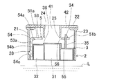
本発明の第1の実施形態に係る燃料遮断弁について、図面を参照にしつつ具体的に説明する。図1に示すように、燃料遮断弁1は、燃料タンク8の上部に装着されている。燃料タンク8の上壁81には、取付穴82が形成されている。燃料遮断弁1は、取付穴82に挿着され、取付穴82の周縁の上壁81に固定されている。燃料遮断弁1の上部には、燃料満タン検知器83が設けられている。燃料遮断弁1は、燃料タンク8の内部と燃料満タン検知器83とを接続する接続通路41をもつ。燃料満タン検知器83は、その通路83aを通じて外部のキャニスタなどに接続される。車両の傾斜、揺動などにより燃料タンク8に貯留されている燃料の液位Lが所定レベルまで上昇したときに、燃料遮断弁1は、接続通路41を閉止して、燃料タンク8の外部に装着されているキャニスタなどに燃料が流出を規制する。
(First embodiment)
A fuel cutoff valve according to a first embodiment of the present invention will be specifically described with reference to the drawings. As shown in FIG. 1, the
燃料遮断弁1は、ケーシング2と、フロート3と、衝撃吸収部材5とを有する。ケーシング2、フロート3、及び衝撃吸収部材5は、いずれも樹脂材料を射出成形して形成される。
The
ケーシング2は、円筒状の側壁部材21と,側壁部材21の上部を覆う蓋部材22とからなる。側壁部材21と蓋部材22とはケース本体部23を構成している。ケース本体部23により囲まれた空間には、弁室42が形成されている。側壁部材21は、周方向の4ヶ所に等間隔に開口するガイド穴26と、燃料タンク8と弁室42とを連通させる通気穴27とをもつ。ガイド゛穴26は、側壁部材21の上下方向に延びる長穴である。
The
蓋部材22の上には、燃料満タン検知器83が配置されている。蓋部材22の中央部は、開口しており、この開口29の周縁からは筒部24が下方に突出している。筒部24の内部には接続通路41が形成されている。接続通路41は、燃料満タン検知器83に連通している。筒部24の下方先端には、周方向全体にシール部25が設けられている。接続通路41は、シール部25を通じて弁室42と連通している。弁室42の下部は、開口しており、燃料タンク8の内部と連通している。従って、弁室42には、燃料タンク8に貯留されている燃料が流入している。
A fuel
図1,図2に示すように、フロート3は、有底の二重円筒体であり、中心部及び外周部にそれぞれ浮力を発生させる中心側空間部31及び外周側空間部32が形成されている。フロート3の上壁33における外周側空間部32の上部に、2つの凹所33aが形成されている。各凹所33aには、先端に鉤部34をもつ突起部35が突設されている。
As shown in FIGS. 1 and 2, the
衝撃吸収部材5は、ケーシング2の蓋部材22と対向する上壁51をもつ。図2に示すように、上壁51の中央部は、接続通路41に対向する平板状部分であり、その周縁にはケーシング2のシール部25に離接するシート部52をもつ。上壁51は、シート部52から径方向外側に放射状に突設された4つの長腕部51a及び4つの短腕部51bをもつ。4つの長腕部51aは、互いに等間隔で配置されている。4つの短腕部51bは、長腕部51aの間の中央に配置されている。
The
各長腕部51aは、シート部52から径方向外側に突設されて先端が自由端である第2アーム部53と、第2アーム部53を囲むようにシート部52から径方向外側に突設された第1アーム部54とをもつ。第2アーム部53と第1アーム部54との間には、スリット50が介在しており、第2アーム部53と第1アーム部54とは互いに非接触である。
Each
第1アーム部54は、径方向に延び互いに対向する第1の一対の直線部分54dと、直線部分54dの径方向外側に連結され周方向に延びる第2の直線部分54eとからなる。第1アーム部54は、シート部52とともに四角形に開口する枠状部を形成している。第2アーム部53は、枠状の第1アーム部54に囲まれている。第2アーム部53の基端は、シート部52に連結されている。第2アーム部53は、基端から径方向外側に向かって、第1アーム部54の第1の直線部分54dと平行に直線状に延びている。
The
第2アーム部53は、基端がシート部52に連結されており、先端が自由端であるため、第2アーム部53全体は、上下方向に弾性変形する板ばねをなす。第2アーム部53の先端の下面には、フロート3の上壁33に当接する当接部53aが突設されている。
Since the base end of the
図1,図2に示すように、第1アーム部54は、フロート3の外縁部まで延びる上壁部54aと、上壁部54aの先端から屈曲してフロート3の側壁34に沿って下方に延びる側壁部54bとをもつ。上壁部54aは、上下方向に弾性変形する板ばねをなし、基端がシート部52に連結され、先端が側壁部54bに連結されている。側壁部54bは、本願発明の延長部に相当し、ケース本体部23の側壁に対向して、衝撃吸収部材5の昇降方向に延びている。側壁部54bの基端部である上部は、上壁部54aに連結され、側壁部54bの下方の先端である下部は自由端である。側壁部54bは上下方向に移動し、この側壁部54bの移動によって、上壁部54aは上下方向に弾性変形する。側壁部54bの外周面には、ケーシング2のケース本体部23のガイド穴26に係止される爪状の係止部54cが突設している。係止部54cは、ガイド穴26の中を上下方向に移動可能であり、ガイド穴26の下端26aに係止されることで、衝撃吸収部材5の最下位の位置を規定している。第2アーム部53と第1アーム部54は、シート部52から径方向外側に突設された弾性をもつ張出し部を構成している。
As shown in FIGS. 1 and 2, the
4つの短腕部51bには、それぞれ開口55が形成されている。4つの短腕部51bに形成された4つの開口55のうち、相対する位置に配置されている2つの開口55は、フロート3の上壁33から突出する鉤部34が係合する係合部である。衝撃吸収部材5は、フロート3の上壁33との間に隙間30を設けている。フロート上昇時に当接部53aがフロート3の上壁33へ当接したとき、及びフロート下降時に鉤部34が開口55へ係合したときのいずれも、衝撃吸収部材5とフロート3の上壁33との間には隙間30が確保されている。
Each of the four
次に、燃料遮断弁1の作動について説明する。図1に示すように、燃料タンク8の燃料の揺動、給油などの原因により燃料遮断弁1の弁室42に流入している燃料の液位Lが上昇すると、フロート3の中心側空間部31及び外周側空間部32は燃料蒸気で満たされているため、フロート3の浮力が増加する。フロート3の浮力が増加すると、フロート3は、その上に配置された衝撃吸収部材5の当接部53aに当接して、衝撃吸収部材5とともに弁室42の中を上昇する。やがて、衝撃吸収部材5のシート部52が、ケーシング2の筒部24の下方先端に形成されたシール部25に当接して、接続通路41を閉止する。
Next, the operation of the
ここで、当接部53aは、弾性をもつ第2アーム部53の先端に設けられており、第2アーム部53の基端側には、シート部52が配置されている。このため、フロート上昇時にフロート3が当接部53aに当接して、第2アーム部53を上方に弾性変形させる。したがって、第2アーム部53によって、シール部25のシート部52への当接時の衝撃が吸収され、衝撃音が軽減される。
Here, the
次に、図3に示すように、燃料の揺動、減量などの原因により弁室42内の燃料の液位Lが下降すると、フロート3の浮力が減少する。これにより、フロート3は、弁室42内を下降する。フロート3は、鉤部34で衝撃吸収部材5の開口55に係合して、衝撃吸収部材5とともに下降する。衝撃吸収部材5に設けられているシート部52は、ケーシング2のシール部25から離れ、接続通路41を開放させる。
Next, as shown in FIG. 3, when the liquid level L of the fuel in the
更に、衝撃吸収部材5がフロート3とともに弁室42内を下降すると、衝撃吸収部材5の第1アーム部54の先端に設けられている係止部54cが、ケーシング2の側壁部材21に開口するガイド穴26の下端部26aに係止される。これにより、衝撃吸収部材5の下降が停止し、また、衝撃吸収部材5に固定されているフロート3の下降も停止する。
Further, when the
ここで、係止部54cは、弾性を有する第1アーム部54の先端の側壁部54bに設けられており、第1アーム部54の基端側であり上壁51には、フロート3の鉤部34に係合している開口55を有している短腕部51bが設けられている。このため、第1アーム部54は、下降するフロート3の鉤部34によって開口55周縁が下方に押圧されることにより下方に弾性変形する。この第1アーム部54の弾性変形により、係止部54cがガイド穴26の下端部26aに当接したときの衝撃が吸収される。ゆえに、係止部54cがガイド穴26の下端26aに係止するときに発生する衝撃音が軽減される。
Here, the locking
以上のように、第1の実施形態においては、衝撃吸収部材5に、フロート3の上昇時に弾性変形する第2アーム部53と、下降時に弾性変形する第1アーム部54とを設けているため,フロート3が上昇下降の際に発生する衝撃音を低減することができる。
As described above, in the first embodiment, the
(第2の実施形態)
第2の実施形態は、図4に示すように、衝撃吸収部材5が、ケーシング2に保持されている点が、第1の実施形態と相違する。
(Second Embodiment)
As shown in FIG. 4, the second embodiment is different from the first embodiment in that the
衝撃吸収部材5は、第1の実施形態と同様に、第2アーム部53、当接部53a、第1アーム部54、係止部54c、及び開口55をもつ。図4、図5に示すように、係止部54cは、ケース本体部23の側壁部材21に形成された穴部28に係止されている。この穴部28は、第1の実施形態のガイド穴とは異なり、係止部54cを上下動させることなく係止部54cを係止保持している。また、開口55には、フロート3の上壁33から突出した突起部35が上下動可能に挿入されている。突起部35の先端に形成されている鉤部34は、フロート3が下降して最下位に位置するときに開口55に係止する。
The
衝撃吸収部材5の上壁51の中央部には、貫通穴56が形成されている。貫通穴56は、フロート3の上壁33に若干突出したシート部36を進退させるように、シート部36よりも若干大きく開口している。
A through
第2の実施形態に係る燃料遮断弁1の作動について説明する。図4に示すように、弁室42の燃料の液位Lが上昇すると、フロート3は、上昇して、衝撃吸収部材5の当接部53aに当接する。このとき、衝撃吸収部材5の第2アーム部53とフロート3の上壁33との間には、隙間30が介在している。当接部53aは、弾性をもつ第2アーム部53の先端に設けられているため,フロート3に当接するときの衝撃は、第2アーム部53に吸収される。
The operation of the
図6に示すように、フロート3は、第2アーム部53を更に上方に弾性変形させながら、上昇する。フロート3は、第2アーム部53の復元力により速度を抑えながら上昇する。やがて、フロート3のシート部36が、ケーシング2のシール部25に当接して、接続通路41を閉止する。シート部36は、速度を抑えながらシール部25に当接するため、第2アーム部53がない場合とは異なって、シール部25への当接時の衝撃音は軽減される。
As shown in FIG. 6, the
次に、図7に示すように、弁室42の燃料の液位Lが下降すると、フロート3は、下降する。これにより、シート部36は、シール部25から離間して接続通路41を開放する。やがて、フロート3から突出した鉤部34が、衝撃吸収部材5の開口55周縁に係合して、フロート3の下降が停止する。開口55は、第1アーム部54とともに貫通穴56の周縁から突設されている。開口55と係止部54cとの間には、弾性をもつ第1アーム部54が設けられており、第1アーム部54は、下降するフロート3によって開口55周縁が下方に押圧されることにより下方に弾性変形する。この第1アーム部54の弾性変形により、開口55に鉤部34が係合するときの衝撃が吸収される。このため、フロート3降下時に生じる衝撃音を軽減することができる。
Next, as shown in FIG. 7, when the fuel level L in the
(第3の実施形態)
第3の実施形態においては、図8に示すように、第2アーム部53の配置が、第1実施形態と相違する。第2アーム部53の基端は、第1アーム部54の内側面におけるケース本体部23の側壁に近接する部分に連結されている。即ち、第1アーム部54は、径方向に延び互いに対向する第1の一対の直線部分54dと、直線部分54dの径方向外側に連結され周方向に延びる第2の直線部分54eとからなる。第1アーム部54は、シート部52とともに四角形に開口する枠状部を形成している。第2アーム部53の基端は、第2の直線部分54eに連結されている。第2アーム部53は、基端から径方向内側に向かって直線状に延びている。第2アーム部53の先端は、自由端であり、その下面に当接部53aが突設されている。その他の構成は、第1実施形態と同様である。
(Third embodiment)
In the third embodiment, as shown in FIG. 8, the arrangement of the
第3の実施形態の第2アーム部53は、第1実施形態の第2アーム部53と同様に、フロート上昇時に、フロート3に衝撃吸収部材5の当接部53aが当接して、第2アーム部53を上方に弾性変形させる。これにより、衝撃吸収部材5のシート部52がシール部25に当接するときの衝撃音が緩和される。
Similar to the
(第4の実施形態)
第4の実施形態においては、図9に示すように、第2アーム部53の配置が、第1の実施形態と相違する。即ち、第1アーム部54は、径方向に延び互いに対向する第1の一対の直線部分54dと、直線部分54dの径方向外側に連結され周方向に延びる第2の直線部分54eとからなる。第1アーム部54は、シート部52とともに四角形に開口する枠状部を形成している。第2アーム部53の基端は、四角形枠状の第1アーム部54の内側面であって、径方向に延びる一対の第1の直線部分54dのうちの一方の中央部に連結されている。第2アーム部53は、この基端から、径方向と直交する方向、即ち周方向に直線状に延びている。即ち、第2アーム部54は、第1アーム部54の枠状部における第2の直線部分54eの延び方向と平行に延びている。第2アーム部53の延び方向の先端は、自由端であり、その下面に当接部53aが突設されている。その他の構成は、第1実施形態と同様である。
(Fourth embodiment)
In the fourth embodiment, as shown in FIG. 9, the arrangement of the
第4の実施形態においても、第3実施形態と同様に、フロート3の上昇時に、第2アーム部53が上方に弾性変形する。
Also in the fourth embodiment, as in the third embodiment, when the
前記第3及び第4の実施形態の第2アーム部53の配置は、第1の実施形態の燃料遮断弁に適用されるだけでなく、第2の実施形態の燃料遮断弁に適用することもできる。この場合には、第2アーム部は、第2の実施形態の第2アーム部と同様に、フロート上昇時に上方に弾性変形して、フロートやシール部に当接したときの衝撃音を緩和する。
The arrangement of the
前記第1及び第2の実施形態においては、第2アーム部53が枠状の第1アーム部54により囲まれているが、第1アーム部54の外側に配置されていて第1アーム部54により囲まれていなくても良い。例えば、第2アーム部53は、シート部52又は貫通穴56の周縁における第1アーム部54とは周方向の位置が異なる部位に連結されていてもよい。また、第1アーム部5は、枠状でなくても良く、例えば、径方向外側に直線状に延びていてもよい。
In the first and second embodiments, the
前記第1乃至第4の実施形態においては、衝撃吸収部材5の第2アーム部53に設けた当接部53aは、下方に突出して、フロート3の平坦な上壁33に当接しているが、当接部53aは平坦であり、フロート3の上壁33に凸状部を設けて、平坦な当接部53aをフロート3の凸状部に当接させてもよい。
In the first to fourth embodiments, the
前記第1乃至第4の実施形態においては、衝撃吸収部材5の第1アーム部54の先端に設けた係止部54cは径方向外側に向かって爪状に突出して、ケーシング2に設けたガイド穴26又は穴部28に係止しているが、衝撃吸収部材5の第1アーム部54の先端に係止部としてのガイド穴又は穴部を形成し、ケーシング2に径方向内側に突出する爪部を形成して、該爪部をガイド穴又は穴部に係止してもよい。
In the first to fourth embodiments, the locking
前記第1乃至第4の実施形態においては、衝撃吸収部材5には係合部としての開口55が形成されており、開口55には、フロート3から突出する鉤部34が係合しているが、衝撃吸収部材5に下方に突出する突起部の先端に係合部としての鉤部を設け、フロート3の上壁33には開口を設けて、該開口に鉤部を係合してもよい。
In the first to fourth embodiments, the
1:燃料遮断弁、2:ケーシング、3:フロート、5:衝撃吸収部材、8:燃料タンク、21:側壁部材、22:蓋部材、23:ケース本体部、24:筒部、25:シール部、26:ガイド穴、28:穴部、33:上壁、34:鉤部、35:突起部、36:シート部、41:接続通路、42:弁室、50:スリット、51:上壁、51a:長腕部、51b:短腕部、52:シート部、53:第2アーム部、53a:当接部、54:第1アーム部、54a:上壁部、54b:側壁部、54c:係止部、55:開口(係合部)、L:燃料の液位。 1: Fuel cutoff valve, 2: Casing, 3: Float, 5: Shock absorbing member, 8: Fuel tank, 21: Side wall member, 22: Lid member, 23: Case body, 24: Tube, 25: Seal , 26: guide hole, 28: hole, 33: upper wall, 34: flange, 35: protrusion, 36: seat, 41: connection passage, 42: valve chamber, 50: slit, 51: upper wall , 5 1a: Long arm part, 51b: Short arm part, 52: Seat part, 53: Second arm part, 53a: Abutting part, 54: First arm part, 54a: Upper wall part, 54b: Side wall part, 54c : Locking part, 55: Opening (engaging part), L: Fuel level.
Claims (12)
前記接続通路と前記燃料タンクの内部とを連通する弁室と、
該弁室を形成するケース本体部、該ケース本体部の上側に配置され前記弁室に突出して前記接続通路を形成する筒部、及び該筒部の下部に設けられたシール部、を有するケーシングと,
前記弁室に収容され前記弁室内の燃料液位により浮力を増減して昇降するフロートと、
前記シール部と前記フロートとの間に配置され、少なくとも前記フロートが下降するときに該フロートに係合する係合部及び前記シール部に離接するシート部をもち、前記フロートとともに前記弁室を昇降して前記シート部が前記シール部に離接することで前記接続通路を開閉する衝撃吸収部材と、を備え、
該衝撃吸収部材は、前記シート部を径方向の中心部に配置しているとともに該シート部から径方向外側に前記係合部を設けており、前記シート部の径方向外側に突設され弾性を有する第1アーム部、前記第1アーム部又は前記シート部から突設されて先端が自由端であり弾性を有する第2アーム部、前記第2アーム部の前記先端に設けられ上昇する前記フロートに当接する当接部、及び前記第1アーム部の径方向外側の先端に設けられ前記弁室で最下位に位置するときに前記ケース本体部に係止される係止部、を有することを特徴とする燃料遮断弁。 A fuel cutoff valve that is mounted on the upper part of the fuel tank and that opens and closes a connection passage that connects the inside and outside of the fuel tank to cut off communication between the inside and outside of the fuel tank.
A valve chamber communicating the connection passage and the inside of the fuel tank;
A casing having a case main body that forms the valve chamber, a cylindrical portion that is disposed on the upper side of the case main body and protrudes into the valve chamber to form the connection passage, and a seal portion provided at a lower portion of the cylindrical portion When,
A float that is contained in the valve chamber and moves up and down by increasing or decreasing buoyancy depending on the fuel level in the valve chamber;
It is arranged between the seal part and the float, and has at least an engagement part that engages with the float when the float descends and a seat part that comes into contact with and separates from the seal part, and moves up and down the valve chamber together with the float And an impact absorbing member that opens and closes the connection passage by the seat portion being separated from and contacting the seal portion,
The impact absorbing member has the seat portion disposed at the center in the radial direction and the engaging portion provided radially outward from the seat portion. The impact absorbing member protrudes radially outward from the seat portion and is elastic. The first arm portion having the first arm portion, the second arm portion protruding from the first arm portion or the seat portion and having a distal end that is a free end and having elasticity, and the float that is provided and raised at the distal end of the second arm portion An abutting portion that abuts against the case main body, and a locking portion that is provided at a radially outer tip of the first arm portion and is locked to the case body when positioned at the lowest position in the valve chamber. A fuel shut-off valve.
前記ケース本体部に形成された側壁は、前記係止部の昇降をガイドするガイド穴をもち、前記係止部は、前記衝撃吸収部材が前記弁室で最下位に位置するときに前記ガイド穴の下端に係止される請求項1又は2に記載の燃料遮断弁。 The first arm portion has the locking portion at the tip,
The side wall formed in the case main body has a guide hole that guides the lifting and lowering of the locking portion, and the locking portion is located in the guide hole when the shock absorbing member is positioned at the lowest position in the valve chamber. The fuel cutoff valve according to claim 1 or 2, which is locked to a lower end of the fuel.
前記接続通路と前記燃料タンクの内部とを連通する弁室と、
該弁室を形成するケース本体部、該ケース本体部の上側に配置され前記弁室に突出して前記接続通路を形成する筒部、及び該筒部の下部に設けられたシール部、を有するケーシングと,
前記シール部に離接するシート部をもち、前記弁室に収容され該弁室内の燃料液位により浮力を増減して昇降することで、前記シート部が前記シール部に離接して上記接続通路を開閉するフロートと、
前記シール部と前記フロートとの間に配置され前記ケース本体部に保持された衝撃吸収部材と、
を備え、
前記衝撃吸収部材は、径方向の中心部に開口して前記シート部を進退可能にする貫通穴、該貫通穴の周縁から径方向外側に突設され弾性を有する第1アーム部、前記第1アーム部又は前記貫通穴の周縁から突設されて先端が自由端であり弾性を有する第2アーム部、前記第2アーム部の前記先端に設けられ前記フロートに離接する当接部、前記第1アーム部の径方向外側の先端に設けられ前記ケース本体部に係止された係止部、及び前記貫通穴の周縁から径方向外側に設けられ前記フロートが前記弁室で最下位に位置するときに前記フロートに係止される係合部、を有することを特徴とする燃料遮断弁。 A fuel cutoff valve that is mounted on the upper part of the fuel tank and that opens and closes a connection passage that connects the inside and outside of the fuel tank to cut off communication between the inside and outside of the fuel tank.
A valve chamber communicating the connection passage and the inside of the fuel tank;
A casing having a case main body that forms the valve chamber, a cylindrical portion that is disposed on the upper side of the case main body and protrudes into the valve chamber to form the connection passage, and a seal portion provided at a lower portion of the cylindrical portion When,
The seat portion has a seat portion that is separated from and comes into contact with the seal portion, and the seat portion is separated from and comes into contact with the seal portion by moving up and down by increasing or decreasing buoyancy depending on the fuel level in the valve chamber. A float that opens and closes;
An impact absorbing member disposed between the seal portion and the float and held by the case body portion;
With
The shock absorbing member has a through hole that opens at a central portion in the radial direction and allows the seat portion to advance and retreat, a first arm portion that protrudes radially outward from a peripheral edge of the through hole, and has elasticity. A second arm portion that protrudes from the periphery of the arm portion or the through hole and has a free end and has elasticity; an abutment portion that is provided at the tip of the second arm portion and separates from and comes into contact with the float; When the float is positioned at the lowest position in the valve chamber, provided at the distal end on the radially outer side of the arm portion and locked on the case body, and provided radially outward from the periphery of the through hole. The fuel shut-off valve, further comprising an engaging portion locked to the float.
前記ケース本体部に形成された側壁は、前記係止部を係止する穴部をもつ請求項4又は5記載の燃料遮断弁。 The first arm portion has the locking portion at the tip,
The fuel cutoff valve according to claim 4 or 5, wherein the side wall formed in the case main body has a hole for locking the locking portion.
Priority Applications (2)
| Application Number | Priority Date | Filing Date | Title |
|---|---|---|---|
| JP2009190132A JP5359680B2 (en) | 2008-09-17 | 2009-08-19 | Fuel shut-off valve |
| US12/585,260 US8220481B2 (en) | 2008-09-17 | 2009-09-10 | Fuel shutoff valve |
Applications Claiming Priority (3)
| Application Number | Priority Date | Filing Date | Title |
|---|---|---|---|
| JP2008238005 | 2008-09-17 | ||
| JP2008238005 | 2008-09-17 | ||
| JP2009190132A JP5359680B2 (en) | 2008-09-17 | 2009-08-19 | Fuel shut-off valve |
Publications (2)
| Publication Number | Publication Date |
|---|---|
| JP2010095247A JP2010095247A (en) | 2010-04-30 |
| JP5359680B2 true JP5359680B2 (en) | 2013-12-04 |
Family
ID=42006163
Family Applications (1)
| Application Number | Title | Priority Date | Filing Date |
|---|---|---|---|
| JP2009190132A Expired - Fee Related JP5359680B2 (en) | 2008-09-17 | 2009-08-19 | Fuel shut-off valve |
Country Status (2)
| Country | Link |
|---|---|
| US (1) | US8220481B2 (en) |
| JP (1) | JP5359680B2 (en) |
Families Citing this family (10)
| Publication number | Priority date | Publication date | Assignee | Title |
|---|---|---|---|---|
| JP5874601B2 (en) * | 2012-10-31 | 2016-03-02 | 豊田合成株式会社 | Fuel shut-off valve |
| DE102013013213B4 (en) * | 2013-08-09 | 2016-07-07 | Kautex Textron Gmbh & Co. Kg | Operating fluid container with integrated deaerating and / or venting valve |
| WO2015085483A1 (en) | 2013-12-10 | 2015-06-18 | SZ DJI Technology Co., Ltd. | Sensor fusion |
| JP6181300B2 (en) | 2014-09-05 | 2017-08-16 | エスゼット ディージェイアイ テクノロジー カンパニー リミテッドSz Dji Technology Co.,Ltd | System for controlling the speed of unmanned aerial vehicles |
| JP6278539B2 (en) | 2014-09-05 | 2018-02-14 | エスゼット ディージェイアイ テクノロジー カンパニー リミテッドSz Dji Technology Co.,Ltd | Flight mode selection based on situation |
| DK3428766T3 (en) | 2014-09-05 | 2021-06-07 | Sz Dji Technology Co Ltd | MULTI-SENSOR FOR IMAGING THE ENVIRONMENT |
| JP6747459B2 (en) | 2018-01-19 | 2020-08-26 | 京三電機株式会社 | Ventilation control valve for fuel tank |
| DE202020103584U1 (en) * | 2020-01-29 | 2020-07-03 | Alfmeier Präzision SE | Valve |
| WO2021256368A1 (en) * | 2020-06-15 | 2021-12-23 | 株式会社パイオラックス | Valve device |
| WO2022110532A1 (en) * | 2020-11-26 | 2022-06-02 | 皑壹智能汽车科技(嘉兴)有限公司 | Valve, multifunctional combination valve, and cflvv valve |
Family Cites Families (15)
| Publication number | Priority date | Publication date | Assignee | Title |
|---|---|---|---|---|
| JP2549551B2 (en) * | 1988-10-20 | 1996-10-30 | 豊田合成株式会社 | Fuel cut-off valve |
| US5172714A (en) * | 1990-11-30 | 1992-12-22 | Nissan Motor Co., Ltd. | Fuel check valve assembly for fuel tank |
| JP3323289B2 (en) | 1993-07-20 | 2002-09-09 | 株式会社ニフコ | Fuel cut valve |
| JP3152100B2 (en) * | 1995-03-28 | 2001-04-03 | 豊田合成株式会社 | Check valve and fuel tank using the same |
| JP3954155B2 (en) * | 1997-05-13 | 2007-08-08 | 株式会社ニフコ | Liquid outflow prevention valve device |
| US6035884A (en) * | 1997-09-16 | 2000-03-14 | Stant Manufacturing Inc. | Liquid fuel baffle for vent apparatus |
| JPH11190258A (en) * | 1997-12-26 | 1999-07-13 | Mikuni Adec Corp | Fuel shutoff valve |
| JP2002021665A (en) | 2001-05-15 | 2002-01-23 | Nifco Inc | Liquid level detection valve for fuel tank |
| JP3931291B2 (en) * | 2001-11-29 | 2007-06-13 | 豊田合成株式会社 | Fuel tank fuel spill regulating device |
| US6901943B2 (en) * | 2002-07-05 | 2005-06-07 | Toyoda Gosei Co., Ltd. | Apparatus for inhibiting fuels from flowing out of fuel tanks |
| JP4097559B2 (en) * | 2003-04-25 | 2008-06-11 | 豊田合成株式会社 | Fuel tank fuel spill regulating device |
| JP4407534B2 (en) * | 2005-02-28 | 2010-02-03 | 豊田合成株式会社 | Fuel shut-off valve |
| JP4415888B2 (en) * | 2005-03-22 | 2010-02-17 | 豊田合成株式会社 | Fuel shut-off valve |
| US7717126B2 (en) * | 2005-07-08 | 2010-05-18 | Kyosan Denki Co., Ltd. | Float valve structure |
| JP4603949B2 (en) * | 2005-07-29 | 2010-12-22 | 豊田合成株式会社 | Fuel shut-off valve |
-
2009
- 2009-08-19 JP JP2009190132A patent/JP5359680B2/en not_active Expired - Fee Related
- 2009-09-10 US US12/585,260 patent/US8220481B2/en not_active Expired - Fee Related
Also Published As
| Publication number | Publication date |
|---|---|
| US8220481B2 (en) | 2012-07-17 |
| US20100065134A1 (en) | 2010-03-18 |
| JP2010095247A (en) | 2010-04-30 |
Similar Documents
| Publication | Publication Date | Title |
|---|---|---|
| JP5359680B2 (en) | Fuel shut-off valve | |
| JP5437784B2 (en) | Valve device for fuel tank | |
| JP5265262B2 (en) | Float valve device | |
| US8365756B2 (en) | Fuel tank valve device | |
| JP5085347B2 (en) | Check valve integrated cut valve | |
| US11845332B2 (en) | Valve device | |
| EP3599121B1 (en) | Valve device for fuel tank | |
| US6779546B2 (en) | Pressure control valve for fuel tank | |
| US20240255065A1 (en) | Valve device for fuel tank | |
| JP4313289B2 (en) | Fuel tank pump module structure | |
| EP3599122B1 (en) | Valve device for fuel tank | |
| KR101300925B1 (en) | Noise Protective type Vent Valve for Fuel Tank | |
| US12179575B1 (en) | Valve device | |
| WO2012127918A1 (en) | Float valve device | |
| JP2011046369A (en) | Fuel shutting-off valve | |
| JP4807341B2 (en) | Fuel shut-off valve | |
| JP2019180842A (en) | Toilet seat lifting/lowering device | |
| JP2008184093A (en) | Fuel cutoff valve | |
| JPH07127540A (en) | Fuel cut-off valve | |
| JP2008080945A (en) | Fuel shutting-off valve | |
| JP4487915B2 (en) | Fuel shut-off valve | |
| JP4407534B2 (en) | Fuel shut-off valve | |
| JP2007177701A (en) | Fuel shut-off valve | |
| JP4635886B2 (en) | Fuel shut-off valve | |
| JP2009078647A (en) | Fuel shutoff valve |
Legal Events
| Date | Code | Title | Description |
|---|---|---|---|
| A621 | Written request for application examination |
Free format text: JAPANESE INTERMEDIATE CODE: A621 Effective date: 20110822 |
|
| A977 | Report on retrieval |
Free format text: JAPANESE INTERMEDIATE CODE: A971007 Effective date: 20121025 |
|
| A131 | Notification of reasons for refusal |
Free format text: JAPANESE INTERMEDIATE CODE: A131 Effective date: 20121030 |
|
| A521 | Written amendment |
Free format text: JAPANESE INTERMEDIATE CODE: A523 Effective date: 20121115 |
|
| A131 | Notification of reasons for refusal |
Free format text: JAPANESE INTERMEDIATE CODE: A131 Effective date: 20130402 |
|
| A521 | Written amendment |
Free format text: JAPANESE INTERMEDIATE CODE: A523 Effective date: 20130418 |
|
| TRDD | Decision of grant or rejection written | ||
| A01 | Written decision to grant a patent or to grant a registration (utility model) |
Free format text: JAPANESE INTERMEDIATE CODE: A01 Effective date: 20130806 |
|
| A61 | First payment of annual fees (during grant procedure) |
Free format text: JAPANESE INTERMEDIATE CODE: A61 Effective date: 20130819 |
|
| R150 | Certificate of patent or registration of utility model |
Free format text: JAPANESE INTERMEDIATE CODE: R150 |
|
| LAPS | Cancellation because of no payment of annual fees |