JP5353396B2 - COMMUNICATION DEVICE, SIGNAL PROCESSING METHOD, SIGNAL PROCESSING DEVICE, AND MOBILE BODY - Google Patents
COMMUNICATION DEVICE, SIGNAL PROCESSING METHOD, SIGNAL PROCESSING DEVICE, AND MOBILE BODY Download PDFInfo
- Publication number
- JP5353396B2 JP5353396B2 JP2009096195A JP2009096195A JP5353396B2 JP 5353396 B2 JP5353396 B2 JP 5353396B2 JP 2009096195 A JP2009096195 A JP 2009096195A JP 2009096195 A JP2009096195 A JP 2009096195A JP 5353396 B2 JP5353396 B2 JP 5353396B2
- Authority
- JP
- Japan
- Prior art keywords
- unit
- fourier transform
- fast fourier
- preprocessing
- signal
- Prior art date
- Legal status (The legal status is an assumption and is not a legal conclusion. Google has not performed a legal analysis and makes no representation as to the accuracy of the status listed.)
- Expired - Fee Related
Links
Images


Classifications
-
- G—PHYSICS
- G01—MEASURING; TESTING
- G01S—RADIO DIRECTION-FINDING; RADIO NAVIGATION; DETERMINING DISTANCE OR VELOCITY BY USE OF RADIO WAVES; LOCATING OR PRESENCE-DETECTING BY USE OF THE REFLECTION OR RERADIATION OF RADIO WAVES; ANALOGOUS ARRANGEMENTS USING OTHER WAVES
- G01S19/00—Satellite radio beacon positioning systems; Determining position, velocity or attitude using signals transmitted by such systems
- G01S19/01—Satellite radio beacon positioning systems transmitting time-stamped messages, e.g. GPS [Global Positioning System], GLONASS [Global Orbiting Navigation Satellite System] or GALILEO
- G01S19/13—Receivers
- G01S19/24—Acquisition or tracking or demodulation of signals transmitted by the system
-
- G—PHYSICS
- G01—MEASURING; TESTING
- G01S—RADIO DIRECTION-FINDING; RADIO NAVIGATION; DETERMINING DISTANCE OR VELOCITY BY USE OF RADIO WAVES; LOCATING OR PRESENCE-DETECTING BY USE OF THE REFLECTION OR RERADIATION OF RADIO WAVES; ANALOGOUS ARRANGEMENTS USING OTHER WAVES
- G01S19/00—Satellite radio beacon positioning systems; Determining position, velocity or attitude using signals transmitted by such systems
- G01S19/01—Satellite radio beacon positioning systems transmitting time-stamped messages, e.g. GPS [Global Positioning System], GLONASS [Global Orbiting Navigation Satellite System] or GALILEO
- G01S19/13—Receivers
- G01S19/35—Constructional details or hardware or software details of the signal processing chain
- G01S19/37—Hardware or software details of the signal processing chain
Landscapes
- Engineering & Computer Science (AREA)
- Radar, Positioning & Navigation (AREA)
- Remote Sensing (AREA)
- Computer Networks & Wireless Communication (AREA)
- Physics & Mathematics (AREA)
- General Physics & Mathematics (AREA)
- Signal Processing (AREA)
- Position Fixing By Use Of Radio Waves (AREA)
- Analogue/Digital Conversion (AREA)
- Arrangements For Transmission Of Measured Signals (AREA)
Abstract
Description
本発明は、通信装置、信号処理方法、信号処理装置、および移動体に関する。 The present invention relates to a communication device, a signal processing method, a signal processing device, and a mobile object.
近年、人工衛星から送信される航法メッセージを受信して現在位置を計算可能なGPS(Global Positioning System)受信機が、携帯電話やカーナビゲーションシステムに適用されるなど、広く普及している。 In recent years, a GPS (Global Positioning System) receiver that can receive a navigation message transmitted from an artificial satellite and calculate a current position is widely used, such as being applied to a mobile phone or a car navigation system.
具体的には、人工衛星から送信される航法メッセージには、人工衛星の軌道を示す軌道情報、信号の送信時刻などの情報が含まれる。GPS受信機は、4個以上の人工衛星から上記航法メッセージを受信し、航法メッセージに含まれる軌道情報から各人工衛星の位置を算出する。そして、GPS受信機は、各人工衛星の位置と、航法メッセージの送信時刻と受信時刻の差分に基づいて現在の3次元位置を連立方程式により計算することができる。なお、3次元位置を計算する際に4個以上の人工衛星から送信された航法メッセージが必要となるのは、GPS受信機に内蔵される時計と、人工衛星に設けられている原子時計とに誤差が存在するためである。 Specifically, the navigation message transmitted from the artificial satellite includes information such as orbit information indicating the orbit of the artificial satellite and the signal transmission time. The GPS receiver receives the navigation message from four or more artificial satellites, and calculates the position of each artificial satellite from the orbit information included in the navigation message. The GPS receiver can calculate the current three-dimensional position by simultaneous equations based on the position of each artificial satellite and the difference between the transmission time and the reception time of the navigation message. The navigation message transmitted from four or more artificial satellites when calculating the three-dimensional position is required for the clock built in the GPS receiver and the atomic clock provided for the artificial satellite. This is because there is an error.
また、人工衛星は、L1帯、C/Aコードと呼ばれる信号、すなわち、符号長が1,023でありチップレートが1.023MHzである疑似ランダム(PRN:Pseudo−Random Noise)符号で50bpsのデータをスペクトラム拡散し、スペクトラム拡散した信号で1,575.42MHzのキャリアをBPSK(Binary Phase Shift Keying)変調した信号により上記航法メッセージを送信する。 Further, the artificial satellite is a signal called a C / A code in the L1 band, that is, 50 bps data in a pseudo-random (PRN) code having a code length of 1,023 and a chip rate of 1.023 MHz. The above navigation message is transmitted using a signal obtained by performing BPSK (Binary Phase Shift Keying) modulation on a carrier of 1,575.42 MHz using the spectrum spread signal.
したがって、GPS受信機が人工衛星からの信号を受信するには、PRN符号、キャリアおよびデータの同期をとる必要がある。受信信号のPRN符号の同期は、受信信号のPRN符号と自装置で発生したPRN符号との相関を、例えば高速フーリエ変換を用いて演算することにより実現される。 Therefore, in order for the GPS receiver to receive a signal from an artificial satellite, it is necessary to synchronize the PRN code, carrier, and data. Synchronization of the PRN code of the received signal is realized by calculating the correlation between the PRN code of the received signal and the PRN code generated by the own apparatus, for example, using fast Fourier transform.
また、特許文献1には、全周波数の1/L(Lは整数)の周波数成分を得るための高速フーリエ変換をL回行うことにより全周波数成分を得る受信装置が記載されている。この受信装置によれば、高速フーリエ変換結果を保持するメモリの使用量を削減することができる。
しかし、従来の受信装置が行うL回の高速フーリエ変換には、重複する演算が多く含まれる。したがって、従来の受信装置では、演算量および演算時間が増加してしまうという問題があった。 However, the L fast Fourier transforms performed by the conventional receiver include many overlapping operations. Therefore, the conventional receiving apparatus has a problem that the calculation amount and the calculation time increase.
そこで、本発明は、上記問題に鑑みてなされたものであり、本発明の目的とするところは、高速フーリエ変換のための演算時間を短縮することが可能な、新規かつ改良された通信装置、信号処理方法、信号処理装置、および移動体を提供することにある。 Therefore, the present invention has been made in view of the above problems, and an object of the present invention is a new and improved communication apparatus capable of reducing the calculation time for the fast Fourier transform, The object is to provide a signal processing method, a signal processing device, and a moving body.
上記課題を解決するために、本発明のある観点によれば、受信信号をサンプリングするサンプリング部と、前記サンプリング部により得られたサンプリング値を、分割して高速フーリエ変換を行うための前処理を施しつつ取得する前処理実行部と、前記前処理実行部からの出力に基づいて高速フーリエ変換を分割して行う高速フーリエ変換部と、を備える通信装置が提供される。 In order to solve the above-described problem, according to an aspect of the present invention, a sampling unit that samples a received signal and a preprocessing for performing a fast Fourier transform by dividing a sampling value obtained by the sampling unit. There is provided a communication apparatus including a preprocessing execution unit that is acquired while performing, and a fast Fourier transform unit that performs fast Fourier transform by dividing the output based on an output from the preprocessing execution unit.
前記前処理実行部は、周期信号を生成する信号生成部と、前記サンプリング部により得られたサンプリング値と前記信号生成部により生成された前記周期信号の値とを乗算する乗算部と、前記乗算部により得られた乗算値の各々を、前記乗算部により得られた順序において所定間隔で累積し、複数の累積値を得る累積部とを備え、前記高速フーリエ変換部は、前記累積部により得られた前記複数の累積値を高速フーリエ変換してもよい。 The preprocessing execution unit includes a signal generation unit that generates a periodic signal, a multiplication unit that multiplies the sampling value obtained by the sampling unit and the value of the periodic signal generated by the signal generation unit, and the multiplication Each of the multiplication values obtained by the unit is accumulated at predetermined intervals in the order obtained by the multiplication unit, and a plurality of accumulation values are obtained, and the fast Fourier transform unit is obtained by the accumulation unit. The plurality of accumulated values may be subjected to fast Fourier transform.
前記通信装置は、前記前処理実行部を複数備え、前記前処理実行部の各々に含まれる前記信号生成部は、異なる周期を有する周期信号を生成してもよい。 The communication apparatus may include a plurality of the preprocessing execution units, and the signal generation unit included in each of the preprocessing execution units may generate periodic signals having different periods.
前記前処理実行部の各々の前記累積部は、前記乗算値の各々の累積を受信信号の所定長さ単位で行い、前記通信装置は、前記前処理実行部の各々に対応するメモリをさらに備え、前記メモリには、対応する前処理実行部により得られた前記複数の累積値が記録され、前記高速フーリエ変換部は、順次に前記メモリの各々に記録されている前記複数の累積値を高速フーリエ変換してもよい。 The accumulation unit of each of the preprocessing execution units performs accumulation of each of the multiplication values in units of a predetermined length of a received signal, and the communication device further includes a memory corresponding to each of the preprocessing execution units. In the memory, the plurality of accumulated values obtained by the corresponding preprocessing execution unit are recorded, and the fast Fourier transform unit sequentially stores the plurality of accumulated values recorded in each of the memories. Fourier transform may be performed.
前記受信信号は拡散符号によりスペクトラム拡散されており、前記通信装置は、第1の前処理実行部の前記信号生成部と同一の周期を有する周期信号を生成する信号生成部を含み、受信信号が前記所定長さ単位で区切られる位置が前記第1の前処理実行部とで異なる第2の前処理実行部と、前記高速フーリエ変換部による高速フーリエ変換結果に基づいて前記拡散符号の相関点を検出する相関点検出部と、前記第1の前処理実行部により得られた前記複数の累積値の高速フーリエ変換結果に基づいて相関点検出部により検出された相関点、または前記第2の前処理実行部により得られた前記複数の累積値の高速フーリエ変換結果に基づいて相関点検出部により検出された相関点のいずれかを選択する選択部と、をさらに備えてもよい。 The received signal is spread spectrum by a spreading code, and the communication device includes a signal generation unit that generates a periodic signal having the same period as the signal generation unit of the first preprocessing execution unit, and the received signal is A correlation point of the spreading code is determined on the basis of a fast Fourier transform result obtained by the fast Fourier transform unit, and a second pre-process execution unit whose position delimited by the predetermined length unit is different from that of the first pre-process execution unit. Correlation points detected by a correlation point detection unit based on fast Fourier transform results of the plurality of accumulated values obtained by the correlation point detection unit and the first preprocessing execution unit, or the second previous And a selection unit that selects any of the correlation points detected by the correlation point detection unit based on the fast Fourier transform results of the plurality of accumulated values obtained by the processing execution unit.
前記累積部は、前記乗算値の各々の累積を受信信号の所定長さ単位で行い、前記信号生成部は、生成する周期信号の周期を、受信信号の前記所定長さ単位で変更してもよい。 The accumulator performs accumulation of each of the multiplication values in units of a predetermined length of the received signal, and the signal generator may change the period of the periodic signal to be generated in units of the predetermined length of the received signal. Good.
また、上記課題を解決するために、本発明の別の観点によれば、受信信号をサンプリングするステップと、サンプリングにより得られたサンプリング値を、分割して高速フーリエ変換を行うための前処理を施しつつメモリに記録するステップと、前記メモリからの出力に基づいて高速フーリエ変換を分割して行うステップと、を含む信号処理方法が提供される。 In order to solve the above-described problem, according to another aspect of the present invention, a step of sampling a received signal and a preprocessing for performing a fast Fourier transform by dividing a sampling value obtained by sampling are performed. There is provided a signal processing method including a step of recording in a memory while performing and a step of dividing and performing a fast Fourier transform based on an output from the memory.
また、上記課題を解決するために、本発明の別の観点によれば、受信信号をサンプリングするサンプリング部と、前記サンプリング部により得られたサンプリング値を、分割して高速フーリエ変換を行うための前処理を施しつつ取得する前処理実行部と、前記前処理実行部からの出力に基づいて高速フーリエ変換を分割して行う高速フーリエ変換部と、を備える信号処理装置が提供される。 In order to solve the above-described problem, according to another aspect of the present invention, a sampling unit that samples a received signal and a sampling value obtained by the sampling unit are divided and fast Fourier transform is performed. A signal processing apparatus is provided that includes a preprocessing execution unit that performs acquisition while performing preprocessing, and a fast Fourier transform unit that divides and performs a fast Fourier transform based on an output from the preprocessing execution unit.
また、上記課題を解決するために、本発明の別の観点によれば、受信信号をサンプリングするサンプリング部と、前記サンプリング部により得られたサンプリング値を、分割して高速フーリエ変換を行うための前処理を施しつつ取得する前処理実行部と、前記前処理実行部からの出力に基づいて高速フーリエ変換を分割して行う高速フーリエ変換部と、を備える通信装置が搭載された、移動体が提供される。 In order to solve the above-described problem, according to another aspect of the present invention, a sampling unit that samples a received signal and a sampling value obtained by the sampling unit are divided and fast Fourier transform is performed. A mobile unit equipped with a communication device including a preprocessing execution unit that acquires while performing preprocessing, and a fast Fourier transform unit that performs fast Fourier transform by dividing the output based on the output from the preprocessing execution unit. Provided.
以上説明したように本発明にかかる通信装置、信号処理方法、信号処理装置、および移動体よれば、高速フーリエ変換のための演算時間を短縮することができる。 As described above, according to the communication device, the signal processing method, the signal processing device, and the moving body according to the present invention, it is possible to shorten the calculation time for the fast Fourier transform.
以下に添付図面を参照しながら、本発明の好適な実施の形態について詳細に説明する。なお、本明細書及び図面において、実質的に同一の機能構成を有する構成要素については、同一の符号を付することにより重複説明を省略する。 Exemplary embodiments of the present invention will be described below in detail with reference to the accompanying drawings. In addition, in this specification and drawing, about the component which has the substantially same function structure, duplication description is abbreviate | omitted by attaching | subjecting the same code | symbol.
また、本明細書及び図面において、実質的に同一の機能構成を有する複数の構成要素を、同一の符号の後に異なるアルファベットを付して区別する場合もある。例えば、実質的に同一の機能構成を有する複数の構成を、必要に応じて人工衛星10A、10Bおよび10Cのように区別する。ただし、実質的に同一の機能構成を有する複数の構成要素の各々を特に区別する必要がない場合、同一符号のみを付する。例えば、人工衛星10A、10Bおよび10Cを特に区別する必要が無い場合には、単に人工衛星10と称する。
In the present specification and drawings, a plurality of components having substantially the same functional configuration may be distinguished by adding different alphabets after the same reference numeral. For example, a plurality of configurations having substantially the same functional configuration are distinguished as required by
また、以下に示す項目順序に従って当該「発明を実施するための形態」を説明する。
1.人工衛星システムの概要
1−1.GPSによる位置測位の概要
1−2.航法メッセージの構成
1−3.受信機の構成および動作
2.本発明の実施形態の背景
3.第1の実施形態
4.第2の実施形態
5.第3の実施形態
6.第4の実施形態
7.第5の実施形態
8.本発明の実施形態の効果
Further, the “DETAILED DESCRIPTION OF THE INVENTION” will be described according to the following item order.
1. Outline of artificial satellite system 1-1. Outline of positioning by GPS 1-2. Configuration of navigation message 1-3. 1. Configuration and operation of
<1.人工衛星システムの概要>
まず、図1〜図4を参照し、本発明の実施形態にかかる人工衛星システム1について説明する。
<1. Outline of artificial satellite system>
First, an
[1−1.GPSによる位置測位の概要]
図1は、本発明の実施形態にかかる人工衛星システム1の構成を示した説明図である。図1に示したように、当該人工衛星システム1は、複数の人工衛星10A〜10Dと、受信機20と、を備える。
[1-1. Overview of GPS positioning
FIG. 1 is an explanatory diagram showing a configuration of an
人工衛星10(GPS衛星)は、測位衛星システム(GNSS:Global Navigation Satellite System)を構成しており、地球8の上空を周回している。図1には、4個の人工衛星10A〜10Dのみを示しているが、例えば、6軌道面に4個ずつで計24個の人工衛星が地球8の上空を周回する。
The artificial satellite 10 (GPS satellite) constitutes a positioning satellite system (GNSS: Global Navigation Satellite System) and orbits the
また、人工衛星10は、人工衛星の軌道情報や、航法メッセージの送信時刻などのエフェメリス(Ephemeris)情報を含む航法メッセージ(詳細については[1−2.航法メッセージの構成]において説明する。)を送信する。人工衛星10には原子時計が設けられており、送信時刻は、人工衛星10に設けられている原子時計に従って例えば1秒単位で表現される。
The
なお、人工衛星10は、L1帯、C/Aコードと呼ばれるスペクトラム拡散信号により上記航法メッセージを送信する。このスペクトラム拡散信号は、50bpsのデータを疑似ランダム系列の拡散符号(以下、PRN符号と称する。)でスペクトラム拡散し、スペクトラム拡散した信号で1,575.42MHzのキャリアをBPSK変調した信号である。また、PRN符号は、符号長が1,023でありチップレートが1.023MHzである。
The
地球8に存在する受信機20は、人工衛星10A〜10Dから送信される航法メッセージを受信し、受信した航法メッセージに基づいて自装置の現在位置を計算することができる。
The
より詳細には、受信機20は、人工衛星10A〜10Dから送信された航法メッセージを受信し、航法メッセージからエフェメリス情報を取得する。そして、受信機20は、エフェメリス情報から、人工衛星10A〜10Dの位置を算出する。また、受信機20は、エフェメリス情報に含まれる送信時刻と、航法メッセージの受信時刻の差分により、人工衛星10A〜10Dと受信機20の間の距離を算出する。その後、受信機20は、算出した人工衛星10A〜10Dの各々の位置と、人工衛星10A〜10Dの各々と受信機20の間の距離を利用し、受信機20の現在の3次元位置を未知数とした方程式を演算する。
More specifically, the
このように受信機20の現在の3次元位置を演算する際には、4個以上の人工衛星10から送信された航法メッセージが必要となる。これは、受信機20に内蔵される時計(RTC:Real Time Clock)と、人工衛星10に設けられている原子時計とに誤差が存在するためである。
As described above, when the current three-dimensional position of the
また、人工衛星10は、所定周期でエフェメリス情報を更新し、更新したエフェメリス情報を含む航法メッセージを送信する。ここで、人工衛星10は常に移動しているため、エフェメリス情報の更新時から時間が経過するにつれ、エフェメリス情報に基づいて算出される人工衛星10の位置と、実際の人工衛星10の位置との誤差が大きくなる。このため、航法メッセージに含まれるエフェメリス情報には例えば2時間程度の有効期限が設定されている。
The
以上、図1を参照してGPSによる位置測位について概略的に説明した。なお、図1においては受信機20を通信装置の一例として丸印で示しているが、受信機20は、PC(Personal Computer)、家庭用映像処理装置(DVDレコーダ、ビデオデッキなど)、携帯電話、PHS(Personal Handyphone System)、携帯用音楽再生装置、携帯用映像処理装置、PDA(Personal Digital Assistants)、家庭用ゲーム機器、携帯用ゲーム機器、家電機器、および車載器などの情報処理装置であってもよい。
As described above, the positioning by GPS has been schematically described with reference to FIG. In FIG. 1, the
また、受信機20は、人間や貨物などを乗せて移動可能な移動体に搭載されてもよい。例えば、移動体としては、二輪車や三輪車などの自動車や、自転車、バス、電車、新幹線、路面電車、飛行機、船、ボートなどの多様な乗り物があげられる。
In addition, the
[1−2.航法メッセージの構成]
次に、図2を参照し、人工衛星10から送信される航法メッセージの構成について説明する。
[1-2. Navigation message structure]
Next, the configuration of the navigation message transmitted from the
図2は、航法メッセージのフレーム構成を示した説明図である。図2に示したように、航法メッセージの1フレームは、5つのサブフレームから構成される。また、1フレーム長さは30秒であり、1500bitsの情報量を有する。また、最初のサブフレーム1から3つ目のサブフレーム3には、軌道長半径、離心率、平均近点角、昇降点経度、近地点引数、および軌道傾斜角などの要素を算出するためのパラメータや、航法メッセージの送信時刻tocなどのエフェメリス情報が含まれる。一方、4つ目のサブフレーム4および5つ目のサブフレーム5には、全ての人工衛星10で共通のアルマナック(Almanac)情報が含まれる。アルマナック情報は、全ての人工衛星10の6要素や、いずれの人工衛星10が使用可能であるかを示す情報などが含まれる。
FIG. 2 is an explanatory diagram showing the frame structure of the navigation message. As shown in FIG. 2, one frame of the navigation message is composed of five subframes. One frame length is 30 seconds and has an information amount of 1500 bits. In the
また、各サブフレームには、固定パターンであるプリアンブルの後にデータが記載される。各サブフレームは、10ワードで構成され、長さが6秒であり、300bitsの情報量を有する。 In each subframe, data is described after a preamble that is a fixed pattern. Each subframe is composed of 10 words, has a length of 6 seconds, and has an information amount of 300 bits.
また、各ワードは、30ビットで構成され、長さが600msecである。また、各ビットの長さは、C/Aコード(拡散符号)の20周期分である20msecである。したがって、データの伝送速度は50bpsである。また、C/Aコードは、図2に示したように、1周期が1msecであり、PRN符号の1023チップで構成される。 Each word is composed of 30 bits and has a length of 600 msec. The length of each bit is 20 msec, which is 20 periods of the C / A code (spreading code). Therefore, the data transmission rate is 50 bps. Further, as shown in FIG. 2, the C / A code has a period of 1 msec and is composed of 1023 chips of a PRN code.
[1−3.受信機の構成および動作]
図3は、本発明の実施形態にかかる受信機20のハードウェア構成を示した説明図である。図3に示したように、受信機20は、アンテナ212、周波数変換部220、同期捕捉部240、および同期保持部250を含む受信処理部210と、CPU(Central Processing Unit)260と、RTC(Real Time Clock)264と、タイマ268と、メモリ270と、XO(水晶発振器、X’tal Oscillator)272、TCXO(Temperature Compensated X’tal Oscillator)274と、逓倍/分周器276と、を備える。
[1-3. Configuration and operation of receiver]
FIG. 3 is an explanatory diagram showing a hardware configuration of the
XO272は、所定の周波数(例えば、32.768kHz程度)を有する信号D1を発振し、発振した信号D1をRTC264へ供給する。TCXO274は、XO272と異なる周波数(例えば、16.368MHz程度)を有する信号D2を発振し、発振した信号D2を逓倍/分周器276や周波数シンセサイザ228へ供給する。
The
逓倍/分周器276は、TCXO274から供給された信号D2を、CPU260からの指示に基づいて、逓倍、分周またはその双方を行なう。そして、逓倍/分周器276は、逓倍、分周またはその双方を行った信号D4を、周波数変換部220の周波数シンセサイザ228、CPU260、タイマ268、メモリ270、同期捕捉部240、および同期保持部250へ供給する。
The multiplier /
アンテナ212は、人工衛星10から送信された航法メッセージなどの無線信号(例えば、1575.42MHzのキャリアが拡散されたRF信号)を受信し、該無線信号を電気信号D5に変換して周波数変換部220へ供給する。
The
周波数変換部220は、LNA(Low Noise Amplifier)222と、BPF(Band Pass Filter)224と、増幅器226と、周波数シンセサイザ228と、乗算器230と、増幅器232と、LPF(Low Pass Filter)234と、ADC(Analog Digital Converter)236と、を備える。この周波数変換部220は、以下に示すように、アンテナ212により受信された1575.42MHzの高い周波数を有する信号D5を、デジタル信号処理の容易化のために、例えば1.023MHz程度の周波数を有する信号D14にダウンコンバージョンする。
The
LNA222は、アンテナ212から供給された信号D5を増幅し、BPF224へ供給する。BPF224は、SAWフィルタ(Surface Acoustic Wave Filter)から構成され、LNAにより増幅された信号D6の周波数成分のうちで、特定の周波数成分のみを抽出して増幅器226へ供給する。増幅器226は、BPF224により抽出された周波数成分を有する信号D7(周波数FRF)を増幅し、乗算器230へ供給する。
The
周波数シンセサイザ228は、TCXO274から供給される信号D2を利用し、CPU260からの指示D9に基づいて周波数FLOを有する信号D10を生成する。そして、周波数シンセサイザ228は、生成した周波数FLOを有する信号D10を乗算器230へ供給する。
The
乗算器230は、増幅器226から供給される周波数FRFを有する信号D8と、周波数シンセサイザ228から供給される周波数FLOを有する信号D10を乗算する。すなわち、乗算器230は、高周波信号をIF(Intermediate Frequency)信号D11(例えば、1.023MHz程度の周波数を有する中間周波数信号)にダウンコンバージョンする。
増幅器232は、乗算器230によりダウンコンバージョンされたIF信号D11を増幅し、LPF234へ供給する。
The
LPF234は、増幅器232により増幅されたIF信号D12の周波数成分のうちで低周波成分を抽出し、抽出した低周波成分を有する信号D13をADC236へ供給する。なお、図3においては増幅器232とADC236の間にLPF234が配置される例を説明しているが、増幅器232とADC236の間にはBPFが配置されてもよい。
The
ADC236(サンプリング部)は、LPF234から供給されたアナログ形式のIF信号D13をサンプリングすることによりデジタル形式に変換し、デジタル形式に変換したIF信号D14を、同期捕捉部240および同期保持部250へ供給する。
The ADC 236 (sampling unit) converts the analog IF signal D13 supplied from the
同期捕捉部240は、CPU260による制御に基づき、逓倍/分周器276から供給される信号D4を利用し、ADC236から供給されるIF信号D14のPRN符号の同期捕捉を行い、また、IF信号D14のIF周波数を検出する。そして、同期捕捉部240は、PRN符号の位相やIF信号D14のキャリア周波数などを同期保持部250およびCPU260へ供給する。
Based on the control by the
同期保持部250は、CPU260による制御に基づき、逓倍/分周器276から供給される信号D4を利用し、ADC236から供給されるIF信号D14のPRN符号とキャリアの同期保持を行なう。より詳細には、同期保持部250は、同期捕捉部240から供給されるPRN符号の位相やIF信号D14のキャリア周波数を初期値として動作する。また、同期保持部250は、ADC236から供給されるIF信号D14に含まれる航法メッセージを復調し、CPU260へ供給する。なお、同期保持部250は複数のチャンネル用回路を備え、チャンネル用回路の各々が、対応する人工衛星10から送信された信号の同期保持、および航法メッセージの復調を行う。
Based on the control by the
CPU260は、同期保持部250から供給される航法メッセージに基づいて、各人工衛星10の位置や速度を算出し、受信機20の位置を計算する。また、CPU260は、航法メッセージに基づいてRTC264の時間情報の補正を行なったり、制御端子、I/O端子、および付加機能端子などに接続され各種制御を行なったりする。
The
RTC264は、XO272から供給される所定の周波数を有する信号D1を利用して時間を計測する。RTC264が計測する時間は、CPU260により適宜補正される。
The
タイマ268は、逓倍/分周器276から供給される信号D4を利用して計時する。かかるタイマ268は、CPU260による各種制御の開始タイミングを決定する際などに参照される。例えば、CPU260は、同期捕捉部240により捕捉されたPRN符号の位相に基づいて同期保持部250のPRN符号発生器の動作を開始させるタイミングを決定する際に、タイマ268を参照する。
The
メモリ270は、RAM(Random Access Memory)やROM(Read−Only Memory)などからなり、CPU260による作業空間、プログラムの記憶部、航法メッセージの記憶部などとしての機能を有する。メモリ270においては、CPU260等による各種処理を行う際のワークエリアとしてRAMが用いられる。また、入力された各種データをバッファリングする際や、同期保持部250より得られた人工衛星10の軌道情報であるエフェメリスおよびアルマナック、演算過程で生成される中間データ及び演算結果データの保持ためにもRAMが用いられる。また、メモリ270においては、各種プログラムや固定データ等を記憶する手段としてROMが用いられる。また、メモリ270においては、受信機20の電源が切られている間であっても、人工衛星10の軌道情報であるエフェメリスおよびアルマナック、および測位結果の位置情報、TCXO12の誤差量などを記憶する手段として不揮発メモリが用いられる場合がある。
The
なお、図3に示した受信機20の構成のうちで、XO272,TCXO274、アンテナ212、LNA222およびBPF224を除く構成を、1チップからなる集積回路に実装することも可能である。
Note that, among the configurations of the
続いて、図4を参照し、上述した受信機20の動作例を説明する。
Subsequently, an operation example of the above-described
図4は、本発明の実施形態にかかる受信機20の動作例の流れを示したフローチャートである。図4に示したように、受信機20が起動されると、CPU260が初期設定を行う(S42)。続いて、RTC264により1秒がカウントされると(S44)、CPU260は、同期保持部250に含まれる各チャンネル用回路に対して人工衛星10を割当てる(S46)。
FIG. 4 is a flowchart showing a flow of an operation example of the
その後、受信処理部210により航法メッセージが取得されると(S48)、CPU260は実際に保持している少なくとも4個以上の人工衛星10を選択する(S50)。そして、CPU260は、選択した人工衛星10の現在位置、および速度を算出し(S52)、算出された人工衛星10の現在位置、および速度に基づいて受信機20の現在位置、および速度を計算する(S54)。
Thereafter, when the navigation message is acquired by the reception processing unit 210 (S48), the
続いて、CPU260は、計算した受信機20の現在位置、および速度を表す出力メッセージを作成し(S56)、該出力メッセージに応じたコマンド処理を実行した後にS44の処理に戻る(S58)。
Subsequently, the
<2.本発明の実施形態の背景>
次に、図5を参照し、本発明の実施形態の背景を説明する。
<2. Background of Embodiment of the Present Invention>
Next, the background of the embodiment of the present invention will be described with reference to FIG.
図5は、本発明に関連する同期捕捉部240’の構成を示した説明図である。図5に示したように、本発明に関連する同期捕捉部240’は、メモリ32、FFT34、メモリ36、読み出しアドレス制御部38、PRN符号発生部40、FFT42、メモリ44、乗算器46、逆FFT48、および相関点検出部50を備える。
FIG. 5 is an explanatory diagram showing the configuration of the
図5に示したように、ADC236から供給されるIF信号D14はメモリ32に記録され、FFT34は、メモリ32に記録されているIF信号D14を高速フーリエ変換する。FFT34による高速フーリエ変換結果は、メモリ36に記録される。メモリ36に記録された高速フーリエ変換結果は、読み出しアドレス制御部38による制御に基づき、順次に乗算器46へ供給される。
As shown in FIG. 5, the IF signal D14 supplied from the
一方、PRN符号発生部40は、受信信号の拡散に利用されているPRN符号を発生し、PRN符号発生部40により発生されたPRN符号をFFT42が高速フーリエ変換する。FFT42による高速フーリエ変換結果は、メモリ44に記録される。
On the other hand, the
乗算器46は、メモリ36から供給される高速フーリエ変換結果と、メモリ44から供給される高速フーリエ変換結果の複素共役とを乗算する。すなわち、乗算器46は、周波数領域における受信信号のPRN符号と、PRN符号発生部40により発生されたPRN符号との相関の度合を演算する。
The
逆FFT48は、乗算器46から供給される乗算結果を逆高速フーリエ変換する。逆FFT48による逆高速フーリエ変換結果は、時間領域における受信信号のPRN符号と、PRN符号発生部40により発生されたPRN符号との相関を示す。相関点検出部50は、この逆高速フーリエ変換結果に基づき、受信信号のPRN符号と、PRN符号発生部40により発生されたPRN符号が同期する相関点を検出する。
The
ここで、FFT34は、全周波数の1/L(Lは整数)の周波数成分を得るための高速フーリエ変換をL回行うことにより全周波数成分を得ることも可能である。この場合、新たな高速フーリエ変換を行う間にメモリ36に記録されている前回の高速フーリエ変換結果を乗算器46が乗算することにより、新たな高速フーリエ変換結果でメモリ36を更新することができる。したがって、高速フーリエ変換を分割的に行うことにより、メモリ36の容量を削減することができる。
Here, the
しかし、FFT34が行うL回の高速フーリエ変換には、重複する演算が多く含まれる。したがって、FFT34が単独で高速フーリエ変換を分割的に行う場合、演算量および演算時間が増加してしまうという問題があった。
However, the L fast Fourier transforms performed by the
そこで、上記事情を一着眼点にして本発明の実施形態にかかる受信機20を創作するに至った。本発明の実施形態にかかる受信機20は、高速フーリエ変換のための演算時間を短縮することが可能である。以下、このような受信機20の第1の実施形態〜第5の実施形態を説明する。
Therefore, the
<3.第1の実施形態>
実際の受信機20は、例えばADC236が4.096MHzでサンプリングを行い、同期捕捉部240がADC236により得られた数msec分のサンプリング値を入力データとして高速フーリエ変換する。しかし、以下では、説明の便宜上、16個の入力データを利用して高速フーリエ変換を行う例を説明する。
<3. First Embodiment>
In the
図6は、入力データが16個である場合の高速フーリエ変換の演算の流れを示した説明図である。時間領域の入力データx0〜x15は、図6に示した演算により、周波数領域の出力データX0〜X15に変換される。なお、図6中の「W」は「exp(−j2π/16)」である。 FIG. 6 is an explanatory diagram showing the flow of calculation of the fast Fourier transform when there are 16 pieces of input data. The time domain input data x0 to x15 are converted into frequency domain output data X0 to X15 by the calculation shown in FIG. Note that “W” in FIG. 6 is “exp (−j2π / 16)”.
一方、図7〜図10に示すように、高速フーリエ変換を4回に分割して行うことにより出力データX0〜X15を得ることも可能である。 On the other hand, as shown in FIGS. 7 to 10, it is also possible to obtain the output data X0 to X15 by performing the fast Fourier transform divided into four times.
図7〜図10は、高速フーリエ変換を分割的に行う場合の演算の流れを示した説明図である。具体的には、図7は、出力データX0、X8、X4およびX12を得るための演算を示し、図8は、出力データX2、X10、X6およびX14を得るための演算を示す。同様に、図9は、出力データX1、X9、X5およびX13を得るための演算を示し、図10は、出力データX3、X11、X7およびX15を得るための演算を示す。 7 to 10 are explanatory diagrams showing the flow of calculation when the fast Fourier transform is performed in a divided manner. Specifically, FIG. 7 shows operations for obtaining output data X0, X8, X4 and X12, and FIG. 8 shows operations for obtaining output data X2, X10, X6 and X14. Similarly, FIG. 9 shows operations for obtaining output data X1, X9, X5 and X13, and FIG. 10 shows operations for obtaining output data X3, X11, X7 and X15.
ここで、演算過程で得られる各中間データを図11のように定義すると、図8に示した出力データX2、X10、X6およびX14を得るための高速フーリエ変換への入力となる中間データx”4〜x”7は、以下のように表現される。(W^0=W^16=1、W^8=−1) Here, if each intermediate data obtained in the calculation process is defined as shown in FIG. 11, intermediate data x ″ as an input to the fast Fourier transform for obtaining the output data X2, X10, X6 and X14 shown in FIG. 4 to x ″ 7 are expressed as follows. (W ^ 0 = W ^ 16 = 1, W ^ 8 = -1)

このような中間データx”4〜x”7を得るための演算は、入力データと、入力データごとにW^2ずつ位相が変化する信号とを乗算し、乗算値を4個おきに累積する処理と等価である。なお、乗算値の累積間隔は、入力データ数/分割数であるため、入力データ数が16個で分割数が4である本実施形態においては、上記のように4個となる。
In such an operation for obtaining the intermediate data x ″ 4 to x ″ 7, the input data is multiplied by a signal whose phase changes by
同様に、図7に示した出力データX0、X8、X4およびX12を得るための高速フーリエ変換への入力となる中間データx”0〜x”3は以下の数式2のように表現される。 Similarly, intermediate data x ″ 0 to x ″ 3 serving as input to the fast Fourier transform for obtaining the output data X0, X8, X4, and X12 shown in FIG.
このような中間データx”0〜x”3を得るための演算は、入力データと、位相が変化しない信号(または、入力データごとにW^16ずつ位相が変化する信号)とを乗算し、乗算値を4個おきに累積する処理と等価である。 The calculation for obtaining such intermediate data x ″ 0 to x ″ 3 is obtained by multiplying the input data by a signal whose phase does not change (or a signal whose phase changes by W ^ 16 for each input data), This is equivalent to the process of accumulating every fourth multiplication value.
また、出力データX2、X10、X6およびX14を得るための高速フーリエ変換への入力となる中間データx”8〜x”11は以下の数式3のように表現される。
Further, intermediate data x ″ 8 to x ″ 11 that are input to the fast Fourier transform for obtaining the output data X2, X10, X6, and X14 are expressed as the following
このような中間データx”8〜x”11を得るための演算は、入力データと、入力データごとにW^1ずつ位相が変化する信号とを乗算し、乗算値を4個おきに累積する処理と等価である。 In such an operation for obtaining the intermediate data x ″ 8 to x ″ 11, the input data is multiplied by a signal whose phase is changed by W ^ 1 for each input data, and the multiplied values are accumulated every fourth. It is equivalent to processing.
また、出力データX3、X11、X7およびX15を得るための高速フーリエ変換への入力となる中間データx”12〜x”15は以下の数式4のように表現される。
Further, intermediate data x ″ 12 to x ″ 15 that are input to the fast Fourier transform for obtaining the output data X3, X11, X7, and X15 are expressed as the following
このような中間データx”12〜x”15を得るための演算は、入力データと、入力データごとにW^3ずつ位相が変化する信号とを乗算し、乗算値を4個おきに累積する処理と等価である。
In such an operation for obtaining the intermediate data x ″ 12 to x ″ 15, the input data is multiplied by a signal whose phase changes by
以上説明したように、高速フーリエ変換を分割して行う場合、高速フーリエ変換の対象となる中間データx”0〜x”15を、所定の前処理により得ることができる。本実施形態にかかる同期捕捉部240は、ADC236からIF信号D14として供給される入力データの取得と併せて所定の前処理を行うことにより、全周波数成分の高速フーリエ変換結果を得るための処理時間の短縮を図ることができる。以下、このような同期捕捉部240の詳細な構成および動作を説明する。
As described above, when the fast Fourier transform is divided and performed, the intermediate data x ″ 0 to x ″ 15 to be subjected to the fast Fourier transform can be obtained by predetermined preprocessing. The
[3−1 同期捕捉部の構成]
図12は、第1の実施形態にかかる同期捕捉部240の構成を示した説明図である。図12に示したように、第1の実施形態にかかる同期捕捉部240は、前処理実行部310と、メモリ320と、FFT330と、メモリ332と、読み出しアドレス制御部334と、演算制御部336と、PRN符号発生部340と、FFT344(高速フーリエ変換部)と、メモリ348と、乗算器352と、逆FFT356と、相関点検出部360と、を備える。
[3-1 Configuration of synchronization acquisition unit]
FIG. 12 is an explanatory diagram illustrating a configuration of the
また、前処理実行部310は、信号生成部312と、乗算部314と、加算部316と、メモリ318と、を備える。この前処理実行部310は、高速フーリエ変換を分割して行うための前処理を実行する。
Further, the
信号生成部312は、演算制御部336により指示される周期を有する周期信号を生成する。そして、乗算部314が、入力データとしてADC236から供給されるIF信号D14と、信号生成部312により生成された周期信号を乗算する。すなわち、乗算部314は、入力データと、入力データごと(サンプリング間隔ごと)に位相が所定量ずつ変化する信号とを乗算する。
The
加算部316およびメモリ318は、乗算部314により得られた乗算値を、乗算部314により得られた順序において所定間隔で累積する累積部として機能する。具体的には、乗算部314により得られた乗算値とメモリ318のあるアドレスから読み出された累積値とを加算部316が加算し、加算結果で上記アドレスの累積値を更新するという処理を、メモリ318のアドレスを1ずつずらして繰り返す。
The
例えば、メモリ318を4個のデータを記憶可能に構成し、信号生成部312が入力データごとに位相がW^2ずつ変化する周期信号を生成し、入力データ数が16である場合、数式1に示した中間データx”4〜x”7を累積値として得ることができる。
For example, when the
同様に、メモリ318を4個のデータを記憶可能に構成し、信号生成部312が入力データごとに位相が変化しない周期信号を生成し、入力データ数が16である場合、数式2に示した中間データx”0〜x”3を累積値として得ることができる。また、メモリ318を4個のデータを記憶可能に構成し、信号生成部312が入力データごとに位相がW^1ずつ変化する周期信号を生成し、入力データ数が16である場合、数式3に示した中間データx”8〜x”11を累積値として得ることができる。さらに、メモリ318を4個のデータを記憶可能に構成し、信号生成部312が入力データごとに位相がW^3ずつ変化する周期信号を生成し、入力データ数が16である場合、数式4に示した中間データx”12〜x”15を累積値として得ることができる。
Similarly, when the
すなわち、入力データ数が16に達するごとに、演算制御部336が信号生成部312に生成させる周期信号の周期を変化させ、メモリ318をリセットすることにより、中間データx”0〜x”3、x”4〜x”7、x”8〜x”11、x”12〜x”15を順次に得ることができる。
That is, every time the number of input data reaches 16, the
メモリ320には、前処理実行部310により得られる中間データx”0〜x”3、x”4〜x”7、x”8〜x”11、またはx”12〜x”15が順次に記録される。FFT(Fast Fourier Transform)330は、メモリ320に記録されている中間データx”0〜x”3、x”4〜x”7、x”8〜x”11、またはx”12〜x”15のいずれかを高速フーリエ変換する。FFT330による高速フーリエ変換結果は、メモリ332に記録される。メモリ332に記録された高速フーリエ変換結果は、読み出しアドレス制御部334による制御に基づき、順次に乗算器352へ供給される。
The
一方、PRN符号発生部340は、受信信号の拡散に利用されているPRN符号を発生し、PRN符号発生部340により発生されたPRN符号をFFT344が高速フーリエ変換する。FFT344による高速フーリエ変換結果は、メモリ348に記録される。
On the other hand, the PRN
乗算器352は、メモリ332から供給される高速フーリエ変換結果と、メモリ348から供給される高速フーリエ変換結果の複素共役とを乗算する。すなわち、乗算器352は、周波数領域における受信信号のPRN符号と、PRN符号発生部340により発生されたPRN符号との相関の度合を演算する。
The
逆FFT356は、乗算器352から供給される乗算結果を逆高速フーリエ変換する。逆FFT356による逆高速フーリエ変換結果は、時間領域における受信信号のPRN符号と、PRN符号発生部340により発生されたPRN符号との相関を示す。相関点検出部360は、この逆高速フーリエ変換結果に基づき、受信信号のPRN符号と、PRN符号発生部340により発生されたPRN符号が同期する相関点を検出する。
The
[3−2 同期捕捉部の動作]
続いて、図13を参照し、本実施形態にかかる同期捕捉部240の動作の流れを説明する。なお、以下では、説明の便宜上、中間データx”0〜x”3を中間データA、中間データx”4〜x”7を中間データB、中間データx”8〜x”11を中間データC、中間データx”12〜x”15を中間データDと称する。
[3-2 Operation of synchronization acquisition unit]
Next, with reference to FIG. 13, the operation flow of the
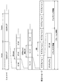
図13は、第1の実施形態にかかる同期捕捉部240の動作の流れを示した説明図である。図13に示したように、前処理実行部310は、演算制御部336による制御に基づき、中間データA、B、C、およびDを得るための前処理を順次に行う。
FIG. 13 is an explanatory diagram showing a flow of operations of the
また、中間データA〜Dの各々を得るための前処理実行部310による各前処理の終了と併せて、前処理により得られた中間データがメモリ320へ転送される。そして、中間データのメモリ転送が終了すると、メモリ320に転送された中間データをFFT330が高速フーリエ変換する。ここで、FFT330により中間データの高速フーリエ変換がおこなわれている間に、前処理実行部310が新たな中間データを得るための前処理を行えるため、全周波数の出力データX0〜X15を得るための処理時間を短縮できる。
In addition, together with the end of each preprocessing by the
<4.第2の実施形態>
以上説明したように、第1の実施形態にかかる同期捕捉部240は、前処理実行部310およびメモリ320を1つずつ備える。これに対し、第2の実施形態にかかる同期捕捉部240は、前処理実行部310およびメモリ320を2つずつ備えることにより、処理時間を一層短縮することができる。
<4. Second Embodiment>
As described above, the
[4−1 同期捕捉部の構成]
図14は、第2の実施形態にかかる同期捕捉部241の構成を示した説明図である。図14に示したように、第2の実施形態にかかる同期捕捉部241は、前処理実行部310Aおよび310Bと、メモリ320Aおよび320Bと、FFT330と、メモリ332と、読み出しアドレス制御部334と、演算制御部336と、PRN符号発生部340と、FFT344と、メモリ348と、乗算器352と、逆FFT356と、相関点検出部360と、を備える。なお、PRN符号発生部340、FFT344、メモリ348、乗算器352、逆FFT356、および相関点検出部360などは第1の実施形態にかかる同期捕捉部240と実質的に同一に構成できるため、説明を省略する。
[4-1 Configuration of synchronization acquisition unit]
FIG. 14 is an explanatory diagram illustrating a configuration of the
本実施形態にかかる前処理実行部310Aおよび310Bは、演算制御部336による制御に基づき、異なる周期を有する周期信号を生成する。このため、前処理実行部310Aおよび310Bの各々からは、異なる中間データが得られる。
The
メモリ320Aには前処理実行部310Aにより得られた中間データが記録され、メモリ320Bには前処理実行部310Bにより得られた中間データが記録される。
Intermediate data obtained by the
[4−2 同期捕捉部の動作]
図15は、第2の実施形態にかかる同期捕捉部241の動作の流れを示した説明図である。図15に示したように、前処理実行部310Aは、演算制御部336による制御に基づき、中間データAを得るための前処理、および中間データCを得るための前処理を交互に行う。また、前処理実行部310Bは、演算制御部336による制御に基づき、中間データBを得るための前処理、および中間データDを得るための前処理を交互に行う。
[4-2 Operation of synchronization acquisition unit]
FIG. 15 is an explanatory diagram showing a flow of operations of the
そして、前処理実行部310Aによる各前処理の終了と併せて、前処理実行部310Aにより得られた中間データがメモリ320Aへ転送される。さらに、中間データのメモリ転送が終了すると、メモリ320Aに転送された中間データをFFT330が高速フーリエ変換する。
Then, along with the end of each preprocessing by the
同様に、前処理実行部310Bによる各前処理の終了と併せて、前処理実行部310Bにより得られた中間データがメモリ320Bへ転送される。さらに、中間データのメモリ転送およびメモリ320Aの中間データの高速フーリエ変換が終了すると、メモリ320Bに転送された中間データをFFT330が高速フーリエ変換する。
Similarly, together with the end of each preprocess by the
このように、第2の実施形態にかかる同期捕捉部241は、前処理実行部310およびメモリ320を複数備えるため、異なる中間データを並列的に得ることができる。その結果、第2の実施形態によれば、第1の実施形態と比較して処理時間を一層短縮することが可能である。
As described above, since the
なお、図15には、前処理実行部310Aによる入力データの取得開始タイミング(図中の立ち上がり)と、前処理実行部310Bによる入力データの取得開始タイミングとが一致する例を示しているが、双方のタイミングは異なってもよい。
FIG. 15 shows an example in which the input data acquisition start timing (rising in the figure) by the
<5.第3の実施形態>
以上説明したように、第1の実施形態にかかる同期捕捉部240および第2の実施形態にかかる同期捕捉部241は、前処理実行部310と同数のメモリ320を備える。これに対し、第3の実施形態にかかる同期捕捉部242においては、メモリ320の数を前処理実行部310より少なくできるため、回路規模の削減を図ることが可能である。
<5. Third Embodiment>
As described above, the
[5−1 同期捕捉部の構成]
図16は、第3の実施形態にかかる同期捕捉部242の構成を示した説明図である。図16に示したように、第3の実施形態にかかる同期捕捉部242は、前処理実行部310A〜310Dと、メモリ320と、FFT330と、メモリ332と、読み出しアドレス制御部334と、演算制御部336と、PRN符号発生部340と、FFT344と、メモリ348と、乗算器352と、逆FFT356と、相関点検出部360と、を備える。なお、PRN符号発生部340、FFT344、メモリ348、乗算器352、逆FFT356、および相関点検出部360などは第1の実施形態にかかる同期捕捉部240と実質的に同一に構成できるため、説明を省略する。
[5-1 Configuration of synchronization acquisition unit]
FIG. 16 is an explanatory diagram illustrating a configuration of the
前処理実行部310A〜310Dの各々は、異なる中間データを得るための前処理を行う。前処理実行部310A〜310Dにより得られた中間データの各々は、順次にメモリ320へ転送される。FFT330は、メモリ320へ転送された中間データを高速フーリエ変換する。
Each of the
[5−2 同期捕捉部の動作]
図17は、第3の実施形態にかかる同期捕捉部242の動作の流れを示した説明図である。図17に示したように、前処理実行部310Aが中間データAを得るための前処理を行い、前処理実行部310Bが中間データBを得るための前処理を行う。同様に、前処理実行部310Cが中間データCを得るための前処理を行い、前処理実行部310Dが中間データDを得るための前処理を行う。
[5-2 Operation of synchronization acquisition unit]
FIG. 17 is an explanatory diagram illustrating a flow of operations of the
そして、前処理実行部310Aによる前処理の終了と併せて、前処理実行部310Aにより得られた中間データAがメモリ320へ転送される。さらに、中間データAのメモリ転送が終了すると、メモリ320に転送された中間データAをFFT330が高速フーリエ変換する。
Then, together with the end of the preprocessing by the
その後、前処理実行部310Bにより得られた中間データBがメモリ320へ転送され、メモリ320に転送された中間データBをFFT330が高速フーリエ変換する。続いて、前処理実行部310Cにより得られた中間データCがメモリ320へ転送され、メモリ320に転送された中間データCをFFT330が高速フーリエ変換する。さらに、前処理実行部310Dにより得られた中間データDがメモリ320へ転送され、メモリ320に転送された中間データDをFFT330が高速フーリエ変換する。
Thereafter, the intermediate data B obtained by the
このように、本実施形態によれば、異なる前処理実行部310A〜310Dにより得られた中間データA〜Dが、順次に同一のメモリ320へ転送される。したがって、本実施形態においては前処理実行部310と同数のメモリ320を設ける必要がないため、回路規模の削減を図ることが可能である。
As described above, according to the present embodiment, the intermediate data A to D obtained by the different
<6.第4の実施形態>
また、以下に説明する第4の実施形態にかかる同期捕捉部243のように、分割数と同数の前処理実行部310およびメモリ320を設けることにより、全周波数の出力データX0〜X15を得るための処理時間をさらに短縮することができる。
<6. Fourth Embodiment>
Further, by providing the same number of
[6−1 同期捕捉部の構成]
図18は、第4の実施形態にかかる同期捕捉部243の構成を示した説明図である。図18に示したように、第4の実施形態にかかる同期捕捉部243は、前処理実行部310A〜310Dと、メモリ320A〜320Dと、FFT330と、メモリ332と、読み出しアドレス制御部334と、演算制御部336と、PRN符号発生部340と、FFT344と、メモリ348と、乗算器352と、逆FFT356と、相関点検出部360と、を備える。なお、PRN符号発生部340、FFT344、メモリ348、乗算器352、逆FFT356、および相関点検出部360などは第1の実施形態にかかる同期捕捉部240と実質的に同一に構成できるため、説明を省略する。
[6-1 Configuration of synchronization acquisition unit]
FIG. 18 is an explanatory diagram illustrating a configuration of the
前処理実行部310A〜310Dの各々は、異なる中間データを得るための前処理を行う。前処理実行部310Aにより得られた中間データはメモリ320Aへ転送され、前処理実行部310Bにより得られた中間データはメモリ320Bへ転送される。同様に、前処理実行部310Cにより得られた中間データはメモリ320Cへ転送され、前処理実行部310Dにより得られた中間データはメモリ320Dへ転送される。
Each of the
FFT330は、メモリ320A〜メモリ320Dへ転送された中間データを順次に高速フーリエ変換する。
The
[6−2 同期捕捉部の動作]
図19は、第4の実施形態にかかる同期捕捉部243の動作の流れを示した説明図である。図19に示したように、前処理実行部310Aが中間データAを得るための前処理を行い、前処理実行部310Bが中間データBを得るための前処理を行う。同様に、前処理実行部310Cが中間データCを得るための前処理を行い、前処理実行部310Dが中間データDを得るための前処理を行う。
[6-2 Operation of synchronization acquisition unit]
FIG. 19 is an explanatory diagram showing a flow of operations of the
そして、前処理実行部310Aによる前処理の終了と併せて、前処理実行部310Aにより得られた中間データAがメモリ320Aへ転送される。また、前処理実行部310Bによる前処理の終了と併せて、前処理実行部310Bにより得られた中間データBがメモリ320Bへ転送される。また、前処理実行部310Cによる前処理の終了と併せて、前処理実行部310Cにより得られた中間データCがメモリ320Cへ転送される。同様に、前処理実行部310Dによる前処理の終了と併せて、前処理実行部310Dにより得られた中間データDがメモリ320Dへ転送される。
Then, along with the end of the preprocessing by the
その後、FFT330は、メモリ320A〜メモリ320Dへ転送された中間データを順次に高速フーリエ変換する。
Thereafter, the
このように、本実施形態によれば、各中間データを得るための前処理および各中間データのメモリ転送を並列的に行うことができるため、全周波数の出力データX0〜X15を得るための処理時間の短縮を図ることが可能である。 As described above, according to the present embodiment, the preprocessing for obtaining each intermediate data and the memory transfer of each intermediate data can be performed in parallel. Therefore, the processing for obtaining the output data X0 to X15 of all frequencies. It is possible to shorten the time.
<7.第5の実施形態>
上記では、説明の便宜上、16個の入力データを高速フーリエ変換のために利用する例を説明したが、実際には、数msec分の入力データを高速フーリエ変換のために利用する。ここで、図2を参照して説明したように、航法メッセージを構成する各ビットの長さは20msecである。したがって、利用する入力データの途中でビット値が切り替わり、PRN符号の相関点を正常に検出できなくなる場合が想定される。第5の実施形態にかかる同期捕捉部244は、このような場合を防止することが可能である。
<7. Fifth Embodiment>
In the above description, for convenience of explanation, an example in which 16 pieces of input data are used for the fast Fourier transform has been described, but actually, input data for several msec is used for the fast Fourier transform. Here, as described with reference to FIG. 2, the length of each bit constituting the navigation message is 20 msec. Therefore, it is assumed that the bit value is switched in the middle of the input data to be used and the correlation point of the PRN code cannot be detected normally. The
[7−1 同期捕捉部の構成]
図20は、第5の実施形態にかかる同期捕捉部244の構成を示した説明図である。図20に示したように、第5の実施形態にかかる同期捕捉部244は、前処理実行部310Aおよび310Bと、メモリ320と、FFT330と、メモリ332と、読み出しアドレス制御部334と、演算制御部336と、PRN符号発生部340と、FFT344と、メモリ348と、乗算器352と、逆FFT356と、相関点検出部360と、選択部364と、を備える。なお、PRN符号発生部340、FFT344、メモリ348、乗算器352、逆FFT356、および相関点検出部360などは第1の実施形態にかかる同期捕捉部240と実質的に同一に構成できるため、説明を省略する。
[7-1 Configuration of synchronization acquisition unit]
FIG. 20 is an explanatory diagram illustrating a configuration of the
前処理実行部310Aおよび310Bは、異なるタイミングで入力データの取得を開始し、同一周期を有する周期信号に基づいて中間データを得るための前処理を行う。前処理実行部310Aにより得られた中間データおよび前処理実行部310Bにより得られた中間データはメモリ320へ転送される。FFT330は、メモリ320へ転送された中間データを順次に高速フーリエ変換する。FFT330による高速フーリエ変換結果は、メモリ332に供給される。
The
乗算器352は、メモリ332から供給される高速フーリエ変換結果と、メモリ348から供給される高速フーリエ変換結果の複素共役とを乗算する。逆FFT356は、乗算器352から供給される乗算結果を逆高速フーリエ変換する。逆FFT356による逆高速フーリエ変換結果は、時間領域における受信信号のPRN符号と、PRN符号発生部340により発生されたPRN符号との相関を示す。相関点検出部360は、この逆高速フーリエ変換結果に基づき、受信信号のPRN符号と、PRN符号発生部340により発生されたPRN符号が同期する相関点を検出する。
The
選択部364は、相関点検出部360からの前処理実行部310Aにより得られた中間データに基づく出力と、前処理実行部310Bにより得られた中間データに基づく出力とを比較し、良好な一方の出力を相関点として選択する。
The
[7−2 同期捕捉部の動作]
図21は、第5の実施形態にかかる同期捕捉部244の動作の流れを示した説明図である。図21に示したように、前処理実行部310Aは、演算制御部336による制御に基づき、中間データA、B、C、およびDを得るための前処理を順次に行う。また、前処理実行部310Bは、演算制御部336による制御に基づき、前処理実行部310Aと異なるタイミングで入力データの取得を開始し、中間データA’、B’、C’、およびD’を得るための前処理を順次に行う。なお、中間データA’は、中間データAと入力データの取得開始タイミングが異なるが、中間データAと同一の周期信号に基づいて得られるデータである。中間データB’、C’、およびD’も同様である。
[7-2 Operation of synchronization acquisition unit]
FIG. 21 is an explanatory diagram showing the flow of the operation of the
そして、前処理実行部310Aによる各前処理の終了と併せて、前処理実行部310Aにより得られた中間データがメモリ320へ転送される。また、前処理実行部310Bによる各前処理の終了と併せて、前処理実行部310Bにより得られた中間データがメモリ320へ転送される。
Then, along with the end of each preprocess by the
FFT330は、メモリ320へ転送された中間データを順次に高速フーリエ変換する。その後、相関点検出部360において、FFT330による中間データの高速フーリエ変換結果とメモリ348から供給される高速フーリエ変換結果とに基づく相関点の検出が行われる。そして、選択部364が、相関点検出部360からの中間データA〜Dの高速フーリエ変換結果に基づく出力または中間データA’〜D’の高速フーリエ変換結果に基づく出力のいずれかを選択する。したがって、本実施形態によれば、入力データの途中でのビット値の切り替わりによりPRN符号の相関点を正常に検出できなくなる場合を防止することができる。
The
<8.本発明の実施形態の効果>
(1)本発明の実施形態によれば、図13、図15などに示したように、中間データを得るための前処理実行部310による前処理と、FFT330による高速フーリエ変換とを同時に行うことができるので、処理時間の短縮を図ることができる。
<8. Effect of Embodiment of the Present Invention>
(1) According to the embodiment of the present invention, as shown in FIGS. 13 and 15, the preprocessing by the
(2)また、本発明の実施形態によれば、FFT330の前段に配されるメモリ320に必要な容量を削減することができる。以下、その理由を説明する。
(2) Further, according to the embodiment of the present invention, it is possible to reduce the capacity required for the
本発明に関連する図5に示した同期捕捉部240’においては、ADC236によりデジタル形式に変換されたデータがそのままメモリ32に記録される。このため、サンプリング周波数がN(kHz)、ビット数がI(Bit)、入力データの長さがM(ms)である場合、メモリ32のサイズはN×M×I(Bit)必要であった。
In the
しかし、入力データのエネルギーの大半は熱雑音であり,ガウス分布に従う乱数とみなすことができる。このため、本発明の実施形態のように入力データの累積を行うことにより、メモリ320に要する容量を削減できる。
However, most of the energy of the input data is thermal noise, and can be regarded as random numbers that follow a Gaussian distribution. Therefore, the capacity required for the
例えば、高速フーリエ変換を16回に分割して行う場合を考える。また、入力データの標準偏差をσ0、前処理実行部310における16回の加算により得られる中間データの標準偏差をσ1とする。さらに、ADC236が適切な閾値処理を行うことで、I(Bit)で表現される最大値Max0を3×σ0と表現すると、以下の数式が成り立つ。
σ1=√16×σ0=4×σ0(分散の加法性より)
For example, consider the case where the fast Fourier transform is divided into 16 times. Further, the standard deviation of the input data is σ0, and the standard deviation of the intermediate data obtained by 16 additions in the
σ1 = √16 × σ0 = 4 × σ0 (from dispersion additivity)
また、中間データの最大値Max1を3×σ1と表現すると、以下の数式が成り立つ。
Max1=3×σ1=12×σ0=4×Max0
Further, when the maximum value Max1 of the intermediate data is expressed as 3 × σ1, the following mathematical formula is established.
Max1 = 3 × σ1 = 12 × σ0 = 4 × Max0
上記式より、Max1がMax0の4倍であるので、各中間データを記憶するためのビット数を、各入力データを記憶する場合より2ビット増やせば十分である。したがって、本発明に関連する同期捕捉部240’のメモリ32にはN×M×I(Bit)の容量が必要であったのに対し、本発明の実施形態のメモリ320にはN×M÷16×(I+2)(Bit)の容量となり、Iは整数であるため、メモリ320の容量を大幅に削減することができる。なお、高速フーリエ変換を4回に分割して行う場合でも、メモリ320に必要な容量はN×M÷4×(I+1)(Bit)であるため、メモリ320の容量を削減することができる。
From the above equation, since Max1 is four times Max0, it is sufficient to increase the number of bits for storing each intermediate data by 2 bits compared to storing each input data. Therefore, the
(3)通常、FFTへ入力されるデータ数は、FFTの性質上、2のべき乗である必要がある。したがって、1023chip/msである受信信号を1.024MHzの倍数でサンプリングする場合、従来は、8ms分のサンプリング値、または16ms分のサンプリングなどしかFFTへの入力データとして利用することができなかった。 (3) Normally, the number of data input to the FFT needs to be a power of 2 due to the nature of the FFT. Therefore, when a received signal of 1023 chips / ms is sampled at a multiple of 1.024 MHz, conventionally, only a sampling value for 8 ms or a sampling for 16 ms can be used as input data to the FFT.
これに対し、本発明の実施形態においては、FFT330へ入力される中間データの数は2のべき乗である必要があるものの、前処理実行部310における加算回数は2以上の整数であれば特に制限されない。そこで、前処理実行部310における加算回数、すなわち、高速フーリエ変換の分割数を適切に設定することにより、任意の整数ms分のサンプリング値を高速フーリエ変換のための入力データとして利用することが可能である。
On the other hand, in the embodiment of the present invention, the number of intermediate data input to the
例えば、前処理実行部310における加算回数、すなわち、高速フーリエ変換の分割数を5に設定することにより、5ms分のサンプリング値を高速フーリエ変換のための入力データとして利用することが可能となる。
For example, by setting the number of additions in the
(4)図18に示したように、第4の実施形態にかかる同期捕捉部243は、前処理実行部310、およびFFT330のへの入力用のメモリ320を複数備える。このため、高速フーリエ変換を前処理に比べて高速に行える場合、図19に示したように、前処理実行部310は、メモリ320への中間データの転送を終了すると次の入力データの取得および前処理を開始することが可能である。
(4) As shown in FIG. 18, the
(5)また、第5の実施形態によれば、複数の前処理実行部310が、異なるタイミングで入力データの取得を開始し、同一周期を有する周期信号に基づいて中間データを得るための前処理を行う。さらに、選択部364が、各前処理実行部310により得られた中間データに基づく相関点検出部360からの出力を比較し、良好な一方の出力を選択する。したがって、第5の実施形態によれば、入力データの途中でのビット値の切り替わりによりPRN符号の相関点を正常に検出できなくなる場合を防止することができる。
(5) Also, according to the fifth embodiment, a plurality of
[補足]
以上、添付図面を参照しながら本発明の好適な実施形態について詳細に説明したが、本発明はかかる例に限定されない。本発明の属する技術の分野における通常の知識を有する者であれば、特許請求の範囲に記載された技術的思想の範疇内において、各種の変更例または修正例に想到し得ることは明らかであり、これらについても、当然に本発明の技術的範囲に属するものと了解される。
[Supplement]
The preferred embodiments of the present invention have been described in detail above with reference to the accompanying drawings, but the present invention is not limited to such examples. It is obvious that a person having ordinary knowledge in the technical field to which the present invention pertains can come up with various changes or modifications within the scope of the technical idea described in the claims. Of course, it is understood that these also belong to the technical scope of the present invention.
240、241、242、243、244 同期捕捉部
310、310A、310B、310C、310D 前処理実行部
312 信号生成部
314 乗算部
316 加算部
318、320、320A、320B、320C、320D、332、348 メモリ
330、344 FFT
336 演算制御部
356 逆FFT
364 選択部
240, 241, 242, 243, 244
336
364 selection part
Claims (6)
前記サンプリング部により得られたサンプリング値を、分割して高速フーリエ変換を行うための前処理を施しつつ取得する前処理実行部と;
前記前処理実行部からの出力に基づいて高速フーリエ変換を分割して行う高速フーリエ変換部と;
を備え、
前記前処理実行部は、
周期信号を生成する信号生成部と、
前記サンプリング部により得られたサンプリング値と前記信号生成部により生成された前記周期信号の値とを乗算する乗算部と、
前記乗算部により得られた乗算値の各々を、前記乗算部により得られた順序において所定間隔で累積し、受信信号の所定長さ単位で複数の累積値を得る累積部と、
を有し、
前記高速フーリエ変換部は、前記累積部により得られた前記複数の累積値を高速フーリエ変換し、
前記前処理実行部として、第1の前処理実行部と、前記第1の前処理実行部の前記信号生成部と同一の周期を有する周期信号を生成する信号生成部を含み、受信信号が前記所定長さ単位で区切られる位置が前記第1の前処理実行部とで異なる第2の前処理実行部と、を有し、
さらに、
前記高速フーリエ変換部による高速フーリエ変換結果に基づいて前記拡散符号の相関点を検出する相関点検出部と;
前記第1の前処理実行部により得られた前記複数の累積値の高速フーリエ変換結果に基づいて前記相関点検出部により検出された相関点、または前記第2の前処理実行部により得られた前記複数の累積値の高速フーリエ変換結果に基づいて前記相関点検出部により検出された相関点のいずれかを選択する選択部と;
を備える、通信装置。 A sampling unit for sampling a received signal that has been spread spectrum by a spreading code ;
A preprocessing execution unit that acquires the sampled value obtained by the sampling unit while performing preprocessing for dividing and performing fast Fourier transform;
A fast Fourier transform unit that performs fast Fourier transform by dividing the output based on the output from the preprocessing execution unit;
With
The pre-processing execution unit
A signal generator for generating a periodic signal;
A multiplication unit that multiplies the sampling value obtained by the sampling unit by the value of the periodic signal generated by the signal generation unit;
Each of the multiplication values obtained by the multiplication unit is accumulated at a predetermined interval in the order obtained by the multiplication unit, and an accumulation unit for obtaining a plurality of accumulated values in a predetermined length unit of the received signal;
Have
The fast Fourier transform unit performs fast Fourier transform on the plurality of accumulated values obtained by the accumulation unit,
The preprocessing execution unit includes a first preprocessing execution unit and a signal generation unit that generates a periodic signal having the same cycle as the signal generation unit of the first preprocessing execution unit, and the received signal is the A second pre-processing execution unit that is different from the first pre-processing execution unit in a position divided by a predetermined length unit;
further,
A correlation point detection unit that detects a correlation point of the spread code based on a result of the fast Fourier transform by the fast Fourier transform unit;
Correlation points detected by the correlation point detection unit based on fast Fourier transform results of the plurality of accumulated values obtained by the first preprocessing execution unit, or obtained by the second preprocessing execution unit A selection unit that selects one of the correlation points detected by the correlation point detection unit based on the fast Fourier transform results of the plurality of accumulated values;
A communication device comprising:
前記メモリには、対応する前処理実行部により得られた前記複数の累積値が記録され、
前記高速フーリエ変換部は、順次に前記メモリの各々に記録されている前記複数の累積値を高速フーリエ変換する、請求項1に記載の通信装置。 The communication device further includes a memory corresponding to each of the preprocessing execution units,
In the memory, the plurality of accumulated values obtained by the corresponding preprocessing execution unit are recorded,
The communication device according to claim 1 , wherein the fast Fourier transform unit performs fast Fourier transform on the plurality of accumulated values sequentially recorded in each of the memories.
前記信号生成部は、生成する周期信号の周期を、受信信号の前記所定長さ単位で変更する、請求項1に記載の通信装置。 The accumulating unit performs accumulation of each of the multiplication values in units of a predetermined length of the received signal,
The communication apparatus according to claim 1 , wherein the signal generation unit changes a period of a periodic signal to be generated in units of the predetermined length of a reception signal.
サンプリングにより得られたサンプリング値を、分割して高速フーリエ変換を行うための前処理を施しつつメモリに記録するステップと;
前記メモリからの出力に基づいて高速フーリエ変換を分割して行うステップと;
を含み、
前記前処理は、
周期信号を生成することと、
前記サンプリングにより得られたサンプリング値と前記周期信号の値とを乗算することと、
前記乗算により得られた乗算値の各々を、前記乗算により得られた順序において所定間隔で累積し、受信信号の所定長さ単位で複数の累積値を得ることと、
を含み、
前記高速フーリエ変換を行うステップは、前記複数の累積値を高速フーリエ変換することを含み、
前記前処理として、第1の前処理と、前記第1の前処理における周期信号と同一の周期を有する周期信号を生成し、受信信号が前記所定長さ単位で区切られる位置が前記第1の前処理とで異なる第2の前処理と、を有し、
さらに、
前記高速フーリエ変換の結果に基づいて前記拡散符号の相関点を検出することと;
前記第1の前処理により得られた前記複数の累積値の高速フーリエ変換結果に基づいて検出された相関点、または前記第2の前処理により得られた前記複数の累積値の高速フーリエ変換結果に基づいて検出された相関点のいずれかを選択することと;
を含む、信号処理方法。 Sampling a received signal that has been spread spectrum with a spreading code ;
Recording the sampled value obtained by sampling into a memory while performing preprocessing for performing fast Fourier transform by dividing;
Dividing and performing a fast Fourier transform based on the output from the memory;
Including
The pretreatment includes
Generating a periodic signal;
Multiplying the sampling value obtained by the sampling with the value of the periodic signal;
Each of the multiplication values obtained by the multiplication is accumulated at predetermined intervals in the order obtained by the multiplication, and a plurality of accumulated values are obtained in a predetermined length unit of the received signal;
Including
Performing the fast Fourier transform includes performing a fast Fourier transform on the plurality of accumulated values;
As the pre-processing, a first pre-processing and a periodic signal having the same period as the periodic signal in the first pre-processing are generated, and the position where the reception signal is divided by the predetermined length unit is the first pre-processing. A second pretreatment different from the pretreatment,
further,
Detecting a correlation point of the spreading code based on the result of the fast Fourier transform;
Correlation points detected based on fast Fourier transform results of the plurality of accumulated values obtained by the first preprocessing, or fast Fourier transform results of the plurality of accumulated values obtained by the second preprocessing. Selecting any of the detected correlation points based on
Including a signal processing method.
前記サンプリング部により得られたサンプリング値を、分割して高速フーリエ変換を行うための前処理を施しつつ取得する前処理実行部と;
前記前処理実行部からの出力に基づいて高速フーリエ変換を分割して行う高速フーリエ変換部と;
を備え、
前記前処理実行部は、
周期信号を生成する信号生成部と、
前記サンプリング部により得られたサンプリング値と前記信号生成部により生成された前記周期信号の値とを乗算する乗算部と、
前記乗算部により得られた乗算値の各々を、前記乗算部により得られた順序において所定間隔で累積し、受信信号の所定長さ単位で複数の累積値を得る累積部と、
を有し、
前記高速フーリエ変換部は、前記累積部により得られた前記複数の累積値を高速フーリエ変換し、
前記前処理実行部として、第1の前処理実行部と、前記第1の前処理実行部の前記信号生成部と同一の周期を有する周期信号を生成する信号生成部を含み、受信信号が前記所定長さ単位で区切られる位置が前記第1の前処理実行部とで異なる第2の前処理実行部と、を有し、
さらに、
前記高速フーリエ変換部による高速フーリエ変換結果に基づいて前記拡散符号の相関点を検出する相関点検出部と;
前記第1の前処理実行部により得られた前記複数の累積値の高速フーリエ変換結果に基づいて前記相関点検出部により検出された相関点、または前記第2の前処理実行部により得られた前記複数の累積値の高速フーリエ変換結果に基づいて前記相関点検出部により検出された相関点のいずれかを選択する選択部と;
を備える、信号処理装置。 A sampling unit for sampling a received signal that has been spread spectrum by a spreading code ;
A preprocessing execution unit that acquires the sampled value obtained by the sampling unit while performing preprocessing for dividing and performing fast Fourier transform;
A fast Fourier transform unit that performs fast Fourier transform by dividing the output based on the output from the preprocessing execution unit;
With
The pre-processing execution unit
A signal generator for generating a periodic signal;
A multiplication unit that multiplies the sampling value obtained by the sampling unit by the value of the periodic signal generated by the signal generation unit;
Each of the multiplication values obtained by the multiplication unit is accumulated at a predetermined interval in the order obtained by the multiplication unit, and an accumulation unit for obtaining a plurality of accumulated values in a predetermined length unit of the received signal;
Have
The fast Fourier transform unit performs fast Fourier transform on the plurality of accumulated values obtained by the accumulation unit,
The preprocessing execution unit includes a first preprocessing execution unit and a signal generation unit that generates a periodic signal having the same cycle as the signal generation unit of the first preprocessing execution unit, and the received signal is the A second pre-processing execution unit that is different from the first pre-processing execution unit in a position divided by a predetermined length unit;
further,
A correlation point detection unit that detects a correlation point of the spread code based on a result of the fast Fourier transform by the fast Fourier transform unit;
Correlation points detected by the correlation point detection unit based on fast Fourier transform results of the plurality of accumulated values obtained by the first preprocessing execution unit, or obtained by the second preprocessing execution unit A selection unit that selects one of the correlation points detected by the correlation point detection unit based on the fast Fourier transform results of the plurality of accumulated values;
A signal processing apparatus comprising:
前記サンプリング部により得られたサンプリング値を、分割して高速フーリエ変換を行うための前処理を施しつつ取得する前処理実行部と;
前記前処理実行部からの出力に基づいて高速フーリエ変換を分割して行う高速フーリエ変換部と;
を備え、
前記前処理実行部は、
周期信号を生成する信号生成部と、
前記サンプリング部により得られたサンプリング値と前記信号生成部により生成された前記周期信号の値とを乗算する乗算部と、
前記乗算部により得られた乗算値の各々を、前記乗算部により得られた順序において所定間隔で累積し、受信信号の所定長さ単位で複数の累積値を得る累積部と、
を有し、
前記高速フーリエ変換部は、前記累積部により得られた前記複数の累積値を高速フーリエ変換し、
前記前処理実行部として、第1の前処理実行部と、前記第1の前処理実行部の前記信号生成部と同一の周期を有する周期信号を生成する信号生成部を含み、受信信号が前記所定長さ単位で区切られる位置が前記第1の前処理実行部とで異なる第2の前処理実行部と、を有し、
さらに、
前記高速フーリエ変換部による高速フーリエ変換結果に基づいて前記拡散符号の相関点を検出する相関点検出部と;
前記第1の前処理実行部により得られた前記複数の累積値の高速フーリエ変換結果に基づいて前記相関点検出部により検出された相関点、または前記第2の前処理実行部により得られた前記複数の累積値の高速フーリエ変換結果に基づいて前記相関点検出部により検出された相関点のいずれかを選択する選択部と;
を備える通信装置が搭載された、移動体。
A sampling unit for sampling a received signal that has been spread spectrum by a spreading code ;
A preprocessing execution unit that acquires the sampled value obtained by the sampling unit while performing preprocessing for dividing and performing fast Fourier transform;
A fast Fourier transform unit that performs fast Fourier transform by dividing the output based on the output from the preprocessing execution unit;
With
The pre-processing execution unit
A signal generator for generating a periodic signal;
A multiplication unit that multiplies the sampling value obtained by the sampling unit by the value of the periodic signal generated by the signal generation unit;
Each of the multiplication values obtained by the multiplication unit is accumulated at a predetermined interval in the order obtained by the multiplication unit, and an accumulation unit for obtaining a plurality of accumulated values in a predetermined length unit of the received signal;
Have
The fast Fourier transform unit performs fast Fourier transform on the plurality of accumulated values obtained by the accumulation unit,
The preprocessing execution unit includes a first preprocessing execution unit and a signal generation unit that generates a periodic signal having the same cycle as the signal generation unit of the first preprocessing execution unit, and the received signal is the A second pre-processing execution unit that is different from the first pre-processing execution unit in a position divided by a predetermined length unit;
further,
A correlation point detection unit that detects a correlation point of the spread code based on a result of the fast Fourier transform by the fast Fourier transform unit;
Correlation points detected by the correlation point detection unit based on fast Fourier transform results of the plurality of accumulated values obtained by the first preprocessing execution unit, or obtained by the second preprocessing execution unit A selection unit that selects one of the correlation points detected by the correlation point detection unit based on the fast Fourier transform results of the plurality of accumulated values;
A mobile body equipped with a communication device comprising:
Priority Applications (6)
| Application Number | Priority Date | Filing Date | Title |
|---|---|---|---|
| JP2009096195A JP5353396B2 (en) | 2009-04-10 | 2009-04-10 | COMMUNICATION DEVICE, SIGNAL PROCESSING METHOD, SIGNAL PROCESSING DEVICE, AND MOBILE BODY |
| US12/710,624 US8249202B2 (en) | 2009-04-10 | 2010-02-23 | Communication system, signal processing method, signal processing device, and movable body |
| TW099106184A TWI425242B (en) | 2009-04-10 | 2010-03-03 | A communication device, a signal processing method, a signal processing device, and a moving body |
| EP10157016A EP2239593B1 (en) | 2009-04-10 | 2010-03-19 | Communication system, signal processing method, signal processing device, and movable body |
| AT10157016T ATE549639T1 (en) | 2009-04-10 | 2010-03-19 | COMMUNICATION SYSTEM, SIGNAL PROCESSING METHOD, SIGNAL PROCESSING APPARATUS AND MOVABLE BODY |
| CN2010101512653A CN101859292B (en) | 2009-04-10 | 2010-04-02 | Communication system, signal processing method, signal processing device, and movable body |
Applications Claiming Priority (1)
| Application Number | Priority Date | Filing Date | Title |
|---|---|---|---|
| JP2009096195A JP5353396B2 (en) | 2009-04-10 | 2009-04-10 | COMMUNICATION DEVICE, SIGNAL PROCESSING METHOD, SIGNAL PROCESSING DEVICE, AND MOBILE BODY |
Publications (2)
| Publication Number | Publication Date |
|---|---|
| JP2010251850A JP2010251850A (en) | 2010-11-04 |
| JP5353396B2 true JP5353396B2 (en) | 2013-11-27 |
Family
ID=42543065
Family Applications (1)
| Application Number | Title | Priority Date | Filing Date |
|---|---|---|---|
| JP2009096195A Expired - Fee Related JP5353396B2 (en) | 2009-04-10 | 2009-04-10 | COMMUNICATION DEVICE, SIGNAL PROCESSING METHOD, SIGNAL PROCESSING DEVICE, AND MOBILE BODY |
Country Status (6)
| Country | Link |
|---|---|
| US (1) | US8249202B2 (en) |
| EP (1) | EP2239593B1 (en) |
| JP (1) | JP5353396B2 (en) |
| CN (1) | CN101859292B (en) |
| AT (1) | ATE549639T1 (en) |
| TW (1) | TWI425242B (en) |
Families Citing this family (4)
| Publication number | Priority date | Publication date | Assignee | Title |
|---|---|---|---|---|
| US20220007420A1 (en) * | 2020-07-01 | 2022-01-06 | Qualcomm Incorporated | Spreading aspects of random access channel procedure |
| CN114374421A (en) * | 2020-10-15 | 2022-04-19 | 华为技术有限公司 | Ephemeris data transmission method, device, storage medium, chip and system |
| US12337274B2 (en) | 2022-07-01 | 2025-06-24 | Saudi Arabian Oil Company | Methods for absorption and desorption of carbon dioxide |
| US12386078B2 (en) * | 2022-09-20 | 2025-08-12 | Onenav, Inc. | Methods and apparatuses for improved acquisition of modern GNSS signals |
Family Cites Families (10)
| Publication number | Priority date | Publication date | Assignee | Title |
|---|---|---|---|---|
| US6133871A (en) * | 1995-10-09 | 2000-10-17 | Snaptrack, Inc. | GPS receiver having power management |
| WO2002012912A2 (en) * | 2000-08-08 | 2002-02-14 | Enuvis, Inc. | Methods and apparatus for dynamically determining location using a simplified client device |
| EP2273688B1 (en) * | 2001-06-25 | 2016-12-21 | Sony Corporation | Spread spectrum signal demodulating method and apparatus |
| JP3906913B2 (en) | 2001-06-25 | 2007-04-18 | ソニー株式会社 | Spread spectrum signal demodulation method and apparatus |
| JP2003316763A (en) * | 2001-07-04 | 2003-11-07 | Sony Corp | Frequency analysis method and apparatus, and spread spectrum demodulation method and apparatus |
| JP2003255040A (en) * | 2002-02-28 | 2003-09-10 | Sony Corp | GPS receiver and receiving method |
| US7639181B2 (en) * | 2005-07-01 | 2009-12-29 | Sirf Technology Holdings, Inc. | Method and device for tracking weak global navigation satellite system (GNSS) signals |
| US8031816B2 (en) * | 2006-07-17 | 2011-10-04 | Mediatek Inc. | Method and apparatus for determining boundaries of information elements |
| US8275820B2 (en) * | 2007-07-06 | 2012-09-25 | Mediatek Inc. | Variable length FFT system and method |
| JP2009096195A (en) | 2007-09-27 | 2009-05-07 | Fujifilm Corp | Thermal transfer image-receiving sheet |
-
2009
- 2009-04-10 JP JP2009096195A patent/JP5353396B2/en not_active Expired - Fee Related
-
2010
- 2010-02-23 US US12/710,624 patent/US8249202B2/en not_active Expired - Fee Related
- 2010-03-03 TW TW099106184A patent/TWI425242B/en not_active IP Right Cessation
- 2010-03-19 EP EP10157016A patent/EP2239593B1/en not_active Not-in-force
- 2010-03-19 AT AT10157016T patent/ATE549639T1/en active
- 2010-04-02 CN CN2010101512653A patent/CN101859292B/en not_active Expired - Fee Related
Also Published As
| Publication number | Publication date |
|---|---|
| CN101859292B (en) | 2013-01-02 |
| TWI425242B (en) | 2014-02-01 |
| CN101859292A (en) | 2010-10-13 |
| US8249202B2 (en) | 2012-08-21 |
| TW201126195A (en) | 2011-08-01 |
| EP2239593A1 (en) | 2010-10-13 |
| EP2239593B1 (en) | 2012-03-14 |
| US20100260239A1 (en) | 2010-10-14 |
| ATE549639T1 (en) | 2012-03-15 |
| JP2010251850A (en) | 2010-11-04 |
Similar Documents
| Publication | Publication Date | Title |
|---|---|---|
| JP5262932B2 (en) | COMMUNICATION DEVICE, PHASE-LOCKED LOOP, MOBILE BODY, AND COMMUNICATION METHOD | |
| JP6447883B2 (en) | Receiver and method for direct sequence spread spectrum signals | |
| JP5310333B2 (en) | Reception device, signal processing method, and program | |
| US8005315B2 (en) | Spectrum spreading signal demodulation method and apparatus | |
| US6772065B2 (en) | GPS receiver and receiving method | |
| US8362953B2 (en) | Sequential chip correlation array | |
| JP5353396B2 (en) | COMMUNICATION DEVICE, SIGNAL PROCESSING METHOD, SIGNAL PROCESSING DEVICE, AND MOBILE BODY | |
| US6907346B2 (en) | GPS receiver apparatus and receiving method | |
| JP2009002659A (en) | Coherent integration enhancement circuit, positioning circuit, electronic device, coherent integration enhancement method, positioning method, program, and storage medium | |
| JP2005201737A (en) | Communication device | |
| JP2007322233A (en) | Phase modulation sequence playback device | |
| JP5005446B2 (en) | Independent high-sensitivity satellite signal receiver | |
| JP3738766B2 (en) | Communication device | |
| JPWO2009019754A1 (en) | Satellite positioning apparatus and acquisition method | |
| US20060114971A1 (en) | Receiver, apparatus for generating despread code, and method of generating despread code | |
| WO2012023466A1 (en) | Receiver apparatus, reception method and computer program | |
| JP4595855B2 (en) | POSITIONING DEVICE, POSITIONING DEVICE CONTROL METHOD, POSITIONING DEVICE CONTROL PROGRAM, COMPUTER-READABLE RECORDING MEDIUM CONTAINING POSITIONING DEVICE CONTROL PROGRAM | |
| JP2001042022A (en) | Gps receiving device | |
| JP2006046911A (en) | Receiving apparatus and receiving method | |
| JP2001042021A (en) | Gps receiving device | |
| JP2007024766A (en) | Satellite radio wave receiver |
Legal Events
| Date | Code | Title | Description |
|---|---|---|---|
| A621 | Written request for application examination |
Free format text: JAPANESE INTERMEDIATE CODE: A621 Effective date: 20120215 |
|
| A977 | Report on retrieval |
Free format text: JAPANESE INTERMEDIATE CODE: A971007 Effective date: 20130201 |
|
| A131 | Notification of reasons for refusal |
Free format text: JAPANESE INTERMEDIATE CODE: A131 Effective date: 20130212 |
|
| A521 | Request for written amendment filed |
Free format text: JAPANESE INTERMEDIATE CODE: A523 Effective date: 20130329 |
|
| TRDD | Decision of grant or rejection written | ||
| A01 | Written decision to grant a patent or to grant a registration (utility model) |
Free format text: JAPANESE INTERMEDIATE CODE: A01 Effective date: 20130730 |
|
| A61 | First payment of annual fees (during grant procedure) |
Free format text: JAPANESE INTERMEDIATE CODE: A61 Effective date: 20130812 |
|
| R151 | Written notification of patent or utility model registration |
Ref document number: 5353396 Country of ref document: JP Free format text: JAPANESE INTERMEDIATE CODE: R151 |
|
| R250 | Receipt of annual fees |
Free format text: JAPANESE INTERMEDIATE CODE: R250 |
|
| R250 | Receipt of annual fees |
Free format text: JAPANESE INTERMEDIATE CODE: R250 |
|
| R250 | Receipt of annual fees |
Free format text: JAPANESE INTERMEDIATE CODE: R250 |
|
| LAPS | Cancellation because of no payment of annual fees |