JP5342604B2 - Ranging / communication system - Google Patents
Ranging / communication system Download PDFInfo
- Publication number
- JP5342604B2 JP5342604B2 JP2011134624A JP2011134624A JP5342604B2 JP 5342604 B2 JP5342604 B2 JP 5342604B2 JP 2011134624 A JP2011134624 A JP 2011134624A JP 2011134624 A JP2011134624 A JP 2011134624A JP 5342604 B2 JP5342604 B2 JP 5342604B2
- Authority
- JP
- Japan
- Prior art keywords
- impulse
- signal
- communication
- ranging
- distance
- Prior art date
- Legal status (The legal status is an assumption and is not a legal conclusion. Google has not performed a legal analysis and makes no representation as to the accuracy of the status listed.)
- Active
Links
Images


Landscapes
- Radar Systems Or Details Thereof (AREA)
- Transceivers (AREA)
Abstract
Description
本発明は、測距・通信複合システムの技術分野に関するものである。 The present invention relates to the technical field of a combined ranging / communication system.
電波を用いた距離測定、すなわちレーダ機能は既に多くの技術が開示されている。例えば、測距機能として単調に繰り返し送信されるパルスを用いたレーダ等が知られている。 Many techniques have already been disclosed for distance measurement using radio waves, that is, a radar function. For example, a radar using a pulse repeatedly transmitted monotonously as a distance measuring function is known.
また、近年新しいコンセプトの無線通信技術として、数GHzの帯域を利用した超広帯域無線システムであるUWB(Ultra Wide Band)無線システムが注目されている。 In recent years, a UWB (Ultra Wide Band) wireless system, which is an ultra-wideband wireless system using a band of several GHz, has attracted attention as a new concept wireless communication technology.
UWBは、パルス幅がナノ秒程度かそれ以下の超短パルス波を利用したインパルス無線方式である。該インパルスの位置や、位相、振幅などに情報を変調することで通信が可能となる。 UWB is an impulse radio system using an ultrashort pulse wave having a pulse width of about nanoseconds or less. Communication is possible by modulating information to the position, phase, amplitude, etc. of the impulse.
さらに、UWB無線システムではインパルスの送信した時間と該送信波が所定の物体表面で反射し、再び送信源で受信されるまでの時間を計測することによって、所定の物体とUWB波送信源間の測距が高精度に可能であるという特徴がある。 Further, in the UWB wireless system, by measuring the time when the impulse is transmitted and the time until the transmission wave is reflected on the surface of the predetermined object and received again by the transmission source, the UWB wireless transmission system can measure the time between the predetermined object and the UWB wave transmission source. There is a feature that ranging is possible with high accuracy.
一方、測距機能と通信機能を同時に実現する装置の開発も進められており、例えば特許文献1では両機能を同じ装置で実現している。特許文献1では、無線通信装置を用いたデータ通信を行うにあたって、他の無線通信等との干渉を回避するために、予め測距機能を用いて通信範囲を決定し、それに基づいて送信出力を決定するようにしている。
On the other hand, development of a device that simultaneously realizes a distance measuring function and a communication function is also in progress. In
しかしながら、測距機能と通信機能を同時に実現する従来の装置では、測距機能を有する装置と通信機能を有する装置を別々に用意して組み合わせていた。あるいは、両機能を持つ装置を一体化しているが、両機能を同時に使用可能とするのではなく、切り替えて用いるようにしていた。 However, in the conventional device that simultaneously realizes the distance measuring function and the communication function, the device having the distance measuring function and the device having the communication function are separately prepared and combined. Alternatively, the devices having both functions are integrated, but the two functions are not used simultaneously but are switched and used.
そのため、装置を小型・軽量化するのが困難という問題があった。また、両者の機能を同時に使うことができないために、たとえば通信中に通信相手の移動を知る、といったより高度な利用方法が実現できなかった。 Therefore, there is a problem that it is difficult to reduce the size and weight of the apparatus. In addition, since both functions cannot be used at the same time, a more advanced usage method such as knowing the movement of the communication partner during communication cannot be realized.
また、測距機能に用いる周波数帯と通信機能に用いる周波数帯とが異なるため、それぞれの送受信機能が必要になるといった問題もあった。 In addition, since the frequency band used for the distance measuring function is different from the frequency band used for the communication function, there is a problem that each transmission / reception function is required.
そこで、本発明はこれらの問題を解決するためになされたものであり、測距機能と通信機能とを一体化して処理可能な測距・通信複合システムを提供することを目的とする。 Accordingly, the present invention has been made to solve these problems, and an object of the present invention is to provide a combined ranging / communication system capable of processing by integrating a ranging function and a communication function.
この発明の測距・通信複合システムの第1の態様は、所定のインパルス信号を生成する信号生成手段と、前記インパルス信号を所定の搬送波でアップコンバートして送信信号を生成する搬送波変調手段と、前記送信信号を送信する送信アンテナと、を有する送信部と、前記送信信号が対象物で反射されて再び到着した信号を受信する受信アンテナと、前記受信アンテナで受信した受信信号を増幅する増幅手段と、前記増幅手段の出力からインパルス信号を検波する検波手段と、前記検波手段で検波されたインパルス検波結果を入力して前記対象物までの距離を検知する測距回路と、前記インパルス検波結果を入力して前記対象物との通信を行う通信回路と、を有する受信部と、を備え、前記信号生成手段は、前記インパルス信号の連続する2つのインパルスを1組として、第1番目の前記インパルスが出力された後に第2番目の前記インパルスを出力するタイミングをデータに従って所定の基本周期あるいは該基本周期から所定の微小時間の整数倍に相当する遅延時間だけ遅延させるPPM方式により決定して前記第2番目のインパルス信号を出力し、前記測距回路は、前記インパルス信号の各々のインパルスを用いて前記対象物までの距離を検知し、前記通信回路は、前記測距回路と並行して処理されて前記測距回路で前記対象物までの距離が検知されたときに通信を開始し、前記測距回路から前記対象物までの距離を入力して前記送信信号が前記対象物で反射された反射インパルスの受信タイミングを推定して該反射インパルスの入力を遮断し、さらに前記測距回路で前記対象物の移動が検知されたときは前記インパルス検波結果によるデータ復調を中止することを特徴とする測距・通信複合システムである。 A first aspect of the combined ranging / communication system of the present invention includes a signal generation unit that generates a predetermined impulse signal, a carrier wave modulation unit that up-converts the impulse signal with a predetermined carrier wave, and generates a transmission signal; A transmission unit that transmits the transmission signal; a reception antenna that receives a signal that arrives again after the transmission signal is reflected by an object; and an amplifying unit that amplifies the reception signal received by the reception antenna Detection means for detecting an impulse signal from the output of the amplification means, a ranging circuit for detecting the distance to the object by inputting the impulse detection result detected by the detection means, and the impulse detection result. A receiving unit having a communication circuit that inputs and communicates with the object, and the signal generating means includes two continuous impulse signals. The timing at which the second impulse is output after the first impulse is output corresponds to a predetermined basic period or an integral multiple of a predetermined minute period from the basic period according to data. The second impulse signal is determined by a PPM method that is delayed by a delay time, and the ranging circuit detects the distance to the object using each impulse of the impulse signal, and the communication The circuit is processed in parallel with the distance measuring circuit and starts communication when the distance to the object is detected by the distance measuring circuit, and inputs the distance from the distance measuring circuit to the object. the transmission signal is then estimates the reception timing of the reflected impulse being reflected by the object to block the input of the reflected impulse Te, the object further in the distance measuring circuit When the movement of is detected a ranging and communication composite system characterized in that to stop the data demodulation by the impulse detection result.
第2の態様は、前記第1番目のインパルスは、前記基本周期の2倍の周期で出力されるインパルスであることを特徴とする測距・通信複合システムである。 According to a second aspect of the present invention , there is provided a combined ranging / communication system, wherein the first impulse is an impulse output with a period twice the basic period .
第3の態様は、前記第1番目のインパルスは、直前に前記第2番目のインパルスとして出力されたインパルスであることを特徴とする測距・通信複合システムである。 A third aspect is the combined ranging / communication system, wherein the first impulse is an impulse output as the second impulse immediately before.
第4の態様は、前記測距回路は、前記インパルス検波結果をサンプリングしてアナログ値からディジタル値に変換するアナログ・ディジタル変換器と、前記受信部から前記インパルス信号が送信される時刻を基準として前記アナログ・ディジタル変換器でサンプリングを行わせるためのクロック信号を所定のサンプリング周期で出力するタイミング設定手段と、対象物までの距離毎に設けられて前記アナログ・ディジタル変換器から前記ディジタル値を入力して蓄積する複数のレンジビンと、前記蓄積されたディジタル値が所定の閾値を超える前記レンジビンを判定して前記対象物までの距離を検知する距離検知手段と、を有していることを特徴とする測距・通信複合システムである。 According to a fourth aspect, the ranging circuit samples the impulse detection result and converts it from an analog value to a digital value, and a time when the impulse signal is transmitted from the receiving unit. Timing setting means for outputting a clock signal for performing sampling by the analog / digital converter at a predetermined sampling period, and input of the digital value from the analog / digital converter provided for each distance to an object a plurality of range bins that were accumulated, and wherein the stored digital values is a, and distance detection means for detecting a distance to the object to determine the range bin exceeding a predetermined threshold value This is a combined ranging / communication system.
第5の様態は、前記信号生成手段は、前記インパルス信号を生成すると同時にトリガパルスを生成して前記タイミング設定手段に出力し、前記タイミング設定手段は、前記トリガ信号を基準として前記クロック信号を出力することを特徴とする測距・通信複合システムである。 According to a fifth aspect, the signal generation unit generates the impulse signal simultaneously with the generation of the impulse signal and outputs the trigger pulse to the timing setting unit. The timing setting unit outputs the clock signal based on the trigger signal. This is a combined ranging / communication system.
第6の態様は、前記検波手段は、前記インパルス検波結果として前記インパルス信号の振幅を出力し、前記アナログ・ディジタル変換器は、前記インパルス信号の振幅を離散多値データ(多ビットディジタル信号)に変換することを特徴とする測距・通信複合システムである。 In a sixth aspect , the detection means outputs the amplitude of the impulse signal as the impulse detection result, and the analog-digital converter converts the amplitude of the impulse signal into discrete multilevel data (multi-bit digital signal). This is a combined ranging / communication system characterized by conversion.
第7の態様は、前記タイミング設定手段は、前記アナログ・ディジタル変換器に等価的なサンプリングを行わせるための所定の時間幅(オフセット)を順次加算した時間長だけ前記クロック信号を遅らせて出力することを特徴とする測距・通信複合システムである。 According to a seventh aspect , the timing setting means delays and outputs the clock signal by a time length obtained by sequentially adding a predetermined time width (offset) for causing the analog-digital converter to perform equivalent sampling. This is a combined ranging / communication system.
第8の態様は、前記通信回路は、前記インパルス検波結果を入力してデータ復調を行う高速比較器と、前記インパルス検波結果を2値化するための閾値を前記高速比較器に出力するDACと、を備え、前記高速比較器は、前記DACから入力した前記閾値と前記インパルス検波結果とを比較して2値化することによりデータ復調を行うことを特徴とする測距・通信複合システムである。 In an eighth aspect , the communication circuit includes a high-speed comparator that inputs the impulse detection result and performs data demodulation, and a DAC that outputs a threshold value for binarizing the impulse detection result to the high-speed comparator. And the high-speed comparator compares the threshold value input from the DAC with the impulse detection result and binarizes the data to perform data demodulation. .
第9の態様は、前記通信回路は、前記測距回路から前記対象物までの距離を入力して前記インパルス検波結果から前記送信信号の反射波を検知する自局干渉波除去手段をさらに備え、前記自局干渉波除去手段は、前記反射波を検知すると前記高速比較器への入力を遮断することを特徴とする測距・通信複合システムである。 In a ninth aspect , the communication circuit further includes own-station interference wave removing means for detecting a reflected wave of the transmission signal from the impulse detection result by inputting a distance from the distance measuring circuit to the object, When the reflected wave is detected, the local-station interference wave removing means cuts off the input to the high-speed comparator.
第10の態様は、前記通信回路は、前記高速比較器の出力の立ち上がり間隔が前記PPM方式で決定されるインパルスの立上り間隔よりも短いときは前記閾値を大きくする一方、長いときは前記閾値を小さくするように前記DACを制御する演算処理器をさらに備えていることを特徴とする測距・通信複合システムである。
According to a tenth aspect , the communication circuit increases the threshold when the rising interval of the output of the high-speed comparator is shorter than the rising interval of the impulse determined by the PPM method, and increases the threshold when the output is longer. An integrated ranging / communication system, further comprising an arithmetic processor for controlling the DAC so as to be small.
以上説明したように本発明によれば、測距機能と通信機能とを一体化して処理可能な測距・通信複合システムを提供することできる。その結果、測距機能によって通信相手を検知すると同時に通信を開始することが可能となる。 As described above, according to the present invention, it is possible to provide a combined distance measurement / communication system capable of processing by integrating the distance measurement function and the communication function. As a result, the communication function can be started simultaneously with the communication partner being detected by the distance measuring function.
またこの発明によれば、通信中に通信相手が移動した場合にも、測距機能で通信相手の移動を直ちに検知することが可能となり、通信を適切に処理させることが可能となる。 Further, according to the present invention, even when the communication partner moves during communication, it is possible to immediately detect the movement of the communication partner with the distance measuring function, and it is possible to appropriately process the communication.
さらにこの発明によれば、測距機能に使われる電力の面において、通信のためのPPM変調により一種のディザー効果(電力がランダムに周波数拡散される)が得られることから、単調に繰り返し送信されるパルス方式に比べて、ピーク電力の平均値を下げることができ、スペクトルマスクの厳しい(許容される電力値が低い)UWBには有効な方法となる。 Furthermore, according to the present invention, in terms of power used for the ranging function, a kind of dither effect (power is randomly spread in frequency) can be obtained by PPM modulation for communication. Compared with the pulse method, the average value of peak power can be lowered, and this is an effective method for UWB with a severe spectrum mask (low allowable power value).
さらにこの発明によれば、パルス生成器の最小繰り返し周期が比較的長い場合においても、データ変調を高速に行うことが可能となる。 Furthermore, according to the present invention, even when the minimum repetition period of the pulse generator is relatively long, data modulation can be performed at high speed.
さらに、本発明の信号生成手段により、連続する2つのインパルスを1組として第二番目のインパルスに対してデータ変調を行わせるようにする場合には、低繰り返し周期のインパルスレーダにおいても、高速データレートに対応させた通信を実現することが可能となる。また、インパルスを変調することによりレーダパルスのスクランブル効果が得られ、その結果レーダセンサ間の干渉を低減できるといった効果も得られる。 Furthermore, when the signal generating means of the present invention makes data modulation on the second impulse as a set of two consecutive impulses, even in the low-repetition period impulse radar, high-speed data Communication corresponding to the rate can be realized. Further, by modulating the impulse, a scramble effect of the radar pulse can be obtained, and as a result, an effect that interference between radar sensors can be reduced is also obtained.
図面を参照して本発明の好ましい実施の形態における測距・通信複合システムの構成について詳細に説明する。なお、同一機能を有する各構成部については、図示及び説明簡略化のため、同一符号を付して示す。 With reference to the drawings, the configuration of a combined ranging / communication system according to a preferred embodiment of the present invention will be described in detail. In addition, about each structural part which has the same function, the same code | symbol is attached | subjected and shown for simplification of illustration and description.
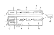
図1は、本発明の実施の形態に係る測距・通信複合システムの概略の構成を示すブロック図である。本発明の測距・通信複合システム1は、送信部2と受信部3から構成されており、測距と通信の2つの機能を統合化している。送信部2は、送信回路4、搬送波変調手段5、及び送信アンテナ6から構成されており、受信部3は、受信回路7、検波器8、低雑音増幅器(LNA)9、及び受信アンテナ10から構成されている。
FIG. 1 is a block diagram showing a schematic configuration of a combined ranging / communication system according to an embodiment of the present invention. The combined ranging /
本発明の測距・通信複合システム1では、超広帯域インパルス方式で送受信を行う。送信回路4において、所定のタイミングで0.5〜1ns程度のベースバンドインパルスを生成し、これを搬送波変調手段5において所定の高周波数帯域、例えば24GHzの搬送波でアップコンバートして送信アンテナ6から送信する。
In the combined ranging /
一方、受信アンテナ10で受信された受信信号は、低雑音増幅器(LNA)9で増幅され、検波器8、例えばダイオード検波器に入力される。検波器8で検波されたインパルス信号は、受信回路7において測距と通信の復調処理が行われる。
On the other hand, a received signal received by the receiving
本発明の測距・通信複合システム1では、測距と通信の復調処理を並列して行えるようにしている。これを実現するために、受信回路7では測距回路11と通信回路12を別々に設けている。
In the combined ranging /
送信回路4で行われるデータ変調は、PPM(Pulse Position Modulation)方式を用いて行っている。PPM方式により生成されるインパルス信号の例を図2に示す。PPM方式のインパルス信号は、所定の基本周期Tでインパルス(a)を生成、あるいは基本周期Tより微小時間dTだけ遅らせてインパルス(b)を生成している。ここで、微小時間dTは基本周期Tより十分短い時間である。
Data modulation performed by the
さらに、基本周期Tは、「PPM変調のための時間スロットdT(2値の場合。多値ではdTの整数倍)」と、パルス送信から次のパルス送信までの信号生成手段として定義できる、「最小パルス繰り返し周期」の和よりも大きい。 Further, the basic period T can be defined as “a time slot dT for PPM modulation (in the case of two values, in the case of multiple values, an integer multiple of dT)” and a signal generation means from pulse transmission to the next pulse transmission. It is larger than the sum of “minimum pulse repetition period”.
PPM方式では、図2に示す通り、基本周期Tで生成されるインパルス(a)と、基本周期TよりdTだけ遅れて生成されるインパルス(b)の2種類があり、例えば前者のインパルス(a)に“0”、後者のインパルス(b)に“1”を割り当てている。送信回路4では、前記所定のタイミングで、変調するデータに応じてインパルス(a)かインパルス(b)のいずれかを割り当てる。
In the PPM system, as shown in FIG. 2, there are two types of impulses (a) generated with a basic period T and impulses (b) generated with a delay of dT from the basic period T. For example, the former impulse (a ) Is assigned "0", and the latter impulse (b) is assigned "1". In the
PPM方式のインパルス信号は、図2に示す“0”か“1”の2値だけでなく、dT単位で多値化することも可能である。例えば、2桁のディジタル符号を送付する場合は、符号”00”、”01”、”10”、”11”にそれぞれ、送信タイミングn×T、n×T+dT、n×T+2×dT、n×T+3×dT、を割り当てることで多値化できる。 The impulse signal of the PPM method can be converted into multi-values in units of dT as well as the binary values “0” or “1” shown in FIG. For example, when sending a two-digit digital code, the transmission timings n × T, n × T + dT, n × T + 2 × are assigned to the codes “00”, “01”, “10”, and “11”, respectively. Multi-value can be obtained by assigning dT, n × T + 3 × dT.
この場合、時間スロットの最大値は3dTとなり、このときの基本周期Tは、3dTと最小パルス繰り返し周期の和よりも大きい。 In this case, the maximum value of the time slot is 3 dT, and the basic period T at this time is larger than the sum of 3 dT and the minimum pulse repetition period.
T≧{3dT+[最小パルス繰り返し周期]}
また、3dT≪Tである。
T ≧ {3dT + [minimum pulse repetition period]}
Further, 3dT << T.
また、通信回路12がプリアンブルを認識するよう構成されている場合には、通信データ送信時に、該通信データに先立って周期Tで同期補足用パルスを所定の回数送信する。
When the
次に測距回路11について、図3を用いて以下で説明する。本発明の測距・通信複合システム1では、送信部2から送信された前記インパルス信号が、対象物13で反射されて受信部3で受信されるまでの所要時間を検知し、該所要時間から対象物13までの距離を判定している。図3は測距回路の一実施形態を示すブロック図であり、タイミング設定手段21、アナログ・ディジタル変換器(ADC)22、レンジビン23、及び距離検知手段24とを備えている。
Next, the
タイミング設定手段21は、送信部2からインパルスが送信される時刻を0として、所定のサンプリング周期でADC22に対しサンプリングを行わせるためのクロック信号を出力する。但し、送信回路4によるデータ変調において、dT の遅延が付加された場合には、サンプリング開始時刻をdTだけ遅延させる。これによって、パルス毎のPPMデータ変調の影響を除去することができる。
The timing setting means 21 outputs a clock signal for causing the
ADC22は、タイミング設定手段21から前記サンプリング周期毎に出力されるクロック信号に従って、検波器8からインパルス検波結果を入力してアナログからディジタルに変換する。ADC22は、高速、広帯域のアナログ・ディジタル変換器であり、該広帯域としては送信回路4で生成されるインパルスのベースバンド帯域と同程度を有している必要がある。
The
検波器8からADC22に入力される前記インパルス検波結果は、受信したインパルスの振幅値であり、該振幅値をADC22でディジタル値に変換している。ディジタル変換された振幅値は、所定のビット数に離散化された離散多値振幅データ(多ビットディジタル信号)である。
The impulse detection result input from the
ADC22のサンプリング速度が十分でない場合には、タイミング設定手段21で設定されるサンプリングクロックに周期的なオフセットを付加することにより、等価的なサンプリングを行わせることが可能である。図4に、前記サンプリングクロックに前記オフセットを付加してサンプリングを行わせる一実施例を示す。
If the sampling rate of the
図4において、第1回目のサンプリングクロック31に対し、第2回目のサンプリングではクロック32をクロック31よりオフセット分33だけ遅らせている。以下同様に、所定の回数だけサンプリングクロックをオフセット分33ずつ遅らせてサンプリングを行う。これにより、ADC22のサンプリング速度を考慮してサンプリングクロックの間隔を長くした場合でも、受信したインパルス信号を適切に検知することが可能となる。
In FIG. 4, the
レンジビン23は、受信したインパルス信号を前記サンプリング周期でサンプリングする所定のサンプリング回数分だけ設けられている。該所定のサンプリング回数は、これにサンプリング周期をかけて得られる時間長が、測距範囲とする最大距離に対応するように決められる。サンプリングが開始されると、ADC22でディジタル化された振幅値を先頭のレンジビンから順に記憶させていく。
The
複数のインパルス信号を受信して測距を行う場合には、各インパルス信号のサンプリングを開始する度に、レンジビン23の先頭から順に前記振幅値を加算していく。そして、前記振幅値の加算を所定の回数実施すると、各レンジビン23に蓄積された前記振幅値の各々の加算値を前記所定の回数で除することでレンジビン23毎の平均値を算出し、これを同じレンジビン23に記憶させる。前記振幅値の加算を行う前記所定の回数を、レンジビン23毎に個別に設定してもよい。
When ranging is performed by receiving a plurality of impulse signals, the amplitude values are added in order from the top of the
上記の通り各レンジビン23に記憶させた前記振幅値あるいは前記振幅値の平均値は、距離検知手段24においてそれぞれ所定の閾値と比較され、該閾値を超える振幅値あるいは振幅値の平均値が検知されると、検知されたレンジビン23の位置から距離が判定される。
As described above, the amplitude value or the average value of the amplitude value stored in each
距離検知手段24による別の測距方法として、レンジビン23に保存された振幅値あるいは振幅値の平均値の中から前記閾値を超えるものが検知されると(該レンジビンを23aとする)、該振幅値あるいは該振幅値の平均値の大きさから対象物13までの距離を推定することが可能である。すなわち、対象物13までの距離が大きくなるにつれて、前記振幅値あるいは前記振幅値の平均値は小さくなることから、前記振幅値あるいは前記振幅値の平均値から対象物13aまでの距離を推定することが可能となる。
As another distance measuring method by the
よって、上記の検知されたレンジビン23aの位置から推定される対象物13までの距離と、レンジビンン23aに保存されている振幅値から推定される距離とを比較することにより、推定された距離が適切か否かを判定することが可能となる。推定された距離が適切と判断されると、分解能の高い方の距離を用いるのが望ましい。
Therefore, the estimated distance is appropriately determined by comparing the distance from the detected position of the
本発明の測距・通信複合システム1では、上記のようにして検知されたレンジビンン23aの位置は、通信回路12に送出されて同期確立のための基礎データとして利用される。
In the combined ranging /
次に、通信回路12について、図面を用いて以下で説明する。図5は、通信回路12の概略構成を示しており、高速比較器(コンパレータ)41と演算処理器42、及びDAC43から構成されている。高速比較器41は、受信信号をアナログ値のまま直接入力し、これをDAC43の出力である、所定の閾値と比較することによって、1か0の2値化を行っている。ここで用いられる前記閾値はDAC43を制御することで可変としており、前記演算処理器42により容易に変更できるようにしている。
Next, the
通信の場合には、プリアンブル信号を用いて同期検出を行う追尾復号モードと、同期検出を行わない逐次復号モードがある。以下では、まず同期検出を行わない逐次復号モードを説明し、その後に同期検出を行う追尾復号モードを説明する。 In the case of communication, there are a tracking decoding mode in which synchronization detection is performed using a preamble signal and a sequential decoding mode in which synchronization detection is not performed. In the following, the sequential decoding mode in which synchronization detection is not performed will be described first, and then the tracking decoding mode in which synchronization detection is performed will be described.
同期検出をしない逐次復号モードを用いた場合、演算処理器42では図6に示すような処理が所定の周期(T'とする)で行われる。以下では、図6を用いて演算処理器42における処理の流れを説明する。
When the sequential decoding mode that does not detect synchronization is used, the
所定の周期T'に達すると、ステップS1ではまず「カウント開始トリガ」がすでに設定されているか否かを判定する。「カウント開始トリガ」がすでに設定されている場合には、ステップS6以降のデータ変調の処理に進む一方、「カウント開始トリガ」が未設定の場合にはステップS2以降の「カウント開始トリガ」の設定処理に進む。 When the predetermined period T ′ is reached, it is first determined in step S1 whether or not a “count start trigger” has already been set. If the “count start trigger” has already been set, the process proceeds to the data modulation process from step S6. On the other hand, if the “count start trigger” has not been set, the “count start trigger” is set from step S2. Proceed to processing.
まず、「カウント開始トリガ」が未設定の場合には、ステップS2において、高速比較器41から入力した2値化されたデータ(以下では"1"を"H"で表し、"0"を"L"で表すものとする)が”H”か否かを判定する。”H”でない場合は、処理を終了して次のデータの入力を待つ。 First, when “count start trigger” is not set, in step S2, binarized data input from the high speed comparator 41 (hereinafter, “1” is represented by “H” and “0” is represented by “ It is determined whether or not “L” is “H”. If it is not “H”, the process is terminated and the next data input is awaited.
”H”が入力された場合には、ステップS3においてこの時のパルス立ち上がりタイミングを「カウント開始トリガ」として記憶する。 If “H” is input, the pulse rising timing at this time is stored as a “count start trigger” in step S3.
ステップS5では、「周期カウンタ」(以下ではMとする)を0に初期化することにより、カウントを開始する。ここでのカウントは、ステップS6で周期T’毎に毎回実施される。 In step S5, the “period counter” (hereinafter referred to as M) is initialized to 0 to start counting. The count here is performed every time period T 'in step S6.
次に、「カウント開始トリガ」がすでに設定されている場合には、まずステップS6で「周期カウンタ」Mに1を加算してカウントする。 Next, if the “count start trigger” has already been set, first, “1” is added to the “period counter” M in step S6 and counted.
続いてステップS7では、カウント値Mが周期Tに相当する回数であるか否かを判定する。即ち、M×T’=Tが成立するか否かを判定し、成立する場合にはステップS8へ、また成立しない場合にはステップS12へ進む。 Subsequently, in step S7, it is determined whether or not the count value M is the number of times corresponding to the period T. That is, it is determined whether or not M × T ′ = T is established. If yes, the process proceeds to step S8, and if not, the process proceeds to step S12.
ステップS8では、「周期カウンタ」Mを再び0に初期化する。これは、一周期T分のサンプリングを終了し、次の周期のサンプリングを開始するためである。 In step S8, “period counter” M is initialized to 0 again. This is because sampling for one period T is completed and sampling for the next period is started.
ステップS9では、高速比較器41から入力した2値化されたデータが”H”か否かを判定する。そして、入力データが”H”の場合には、次のステップS10において受信データとして“0”を復調する。
In step S9, it is determined whether or not the binarized data input from the
一方、ステップS9において入力データが”H”でないと判定された場合には、ステップS11で「データ識別カウンタ」(以下ではNとする)を0に初期化する。これは、dT後のインパルス、すなわち図2(b)のPPM信号をサンプリングするために設定するものである。 On the other hand, if it is determined in step S9 that the input data is not “H”, a “data identification counter” (hereinafter referred to as N) is initialized to 0 in step S11. This is set to sample the impulse after dT, that is, the PPM signal in FIG.
次に、ステップS7においてM×T’=Tが成立しない場合には、ステップS12においてまず、通信相手、すなわち対象物13の移動が検知され、且つカウント開始トリガがdTよりも小さな範囲のずれを生じたか否かを判定する。
Next, when M × T ′ = T does not hold in step S7, first, in step S12, the movement of the communication partner, that is, the
ステップS12の判定が成立する(Y)場合には、ステップS13で「周期カウンタ」Mをリセット(0に初期化)して終了する。また、ステップS12の判定が成立しない(N)場合には、ステップS14以降の処理に進み、図2(b)に示すPPM信号のサンプリング処理を行う。 If the determination in step S12 is true (Y), the “period counter” M is reset (initialized to 0) in step S13 and the process ends. If the determination in step S12 is not satisfied (N), the process proceeds to step S14 and subsequent steps, and the PPM signal sampling process shown in FIG. 2B is performed.
ステップS14では、「周期カウンタ」M及び「データ識別カウンタ」Nをそれぞれカウントする。そして、ステップS15において「データ識別カウンタ」NがdTの時間に相当する回数であるか否かを判定する。即ちM×T’=dTが成立するか否かを判定する。 In step S14, “period counter” M and “data identification counter” N are counted. In step S15, it is determined whether or not the “data identification counter” N is the number of times corresponding to the time of dT. That is, it is determined whether M × T ′ = dT is satisfied.
ステップS15で判定が成立する場合には、次にステップS16で高速比較器41からの入力データが”H”か否かを判定する。そして、入力データが”H”の場合にはステップS17において受信データとして“1”を復調する。また、入力データが”H”でない場合には、図2(b)に示すPPM信号が検知されなかったと判断して、ステップS19で「カウント開始トリガ」をクリアする。
If the determination is established in step S15, it is next determined in step S16 whether or not the input data from the
一方ステップS15で判定が成立しなかった場合には、ステップS18でサンプリング時間がdTを経過しているか否かを判定し、経過している場合にはステップS19で「カウント開始トリガ」をクリアする。「カウント開始トリガ」がクリアされると、再びステップS2で高速比較器41からの入力データが”H”となり、ステップS3で「カウント開始トリガ」が設定されるのを待つ。
On the other hand, if the determination is not satisfied in step S15, it is determined in step S18 whether the sampling time has passed dT, and if it has elapsed, the “count start trigger” is cleared in step S19. . When the “count start trigger” is cleared, the input data from the
通信方式として、プリアンブル信号を用いて同期検出を行う追尾復号モードの場合について、図7を用いて演算処理器42における処理の流れを説明する。
A flow of processing in the
図7に示す処理の流れは、基本的には図6の処理の流れと同じであるが、本通信方式では受信側で同期検出を行うためにプリアアンブルを利用している。プリアンブルを用いる場合、所定の信号を所定回数以上受信したことが確認できたときに、同期を確立したものと判断する。 The processing flow shown in FIG. 7 is basically the same as the processing flow of FIG. 6, but in this communication method, a preamble is used for detecting synchronization on the receiving side. When using a preamble, it is determined that synchronization has been established when it is confirmed that a predetermined signal has been received a predetermined number of times.
また本通信方式の場合には、同期を確立した後T+dTを超えてデータが検出されない場合であっても直ちに周期カウンタ等のリセットは行わず、データとして“”(NULL)を記録して同期を保持する。そして、NULLの記録が所定回数続いた場合にはじめて、同期が外れたものと判断する。 Also, in the case of this communication method, even if data is not detected exceeding T + dT after synchronization is established, the period counter is not reset immediately, and “” (NULL) is recorded as data for synchronization. Hold. Only when NULL recording continues for a predetermined number of times, it is determined that synchronization has been lost.
図7に基づく本通信方式の説明として、以下では図6の同期検出をしない逐次復号モードと異なる点を中心に説明する。 As an explanation of the present communication method based on FIG. 7, the following description will focus on differences from the sequential decoding mode in which synchronization detection is not performed in FIG.
カウント開始トリガの設定が行われるステップS2以下の処理では、ステップS5に代えてステップS21の処理を行う。すなわち、周期カウンタの開始(初期化)に加えて、パルス数カウンタ(Pとする)及びNULLカウンタ(NCとする)を開始する(初期化する)。パルス数カウンタは、上記のプリアンブルの信号をカウントするためのものであり、NULLカウンタはNULLの記録回数をカウントするためのものである。 In the processing after step S2 in which the count start trigger is set, the processing of step S21 is performed instead of step S5. That is, in addition to the start (initialization) of the cycle counter, the pulse number counter (P) and the NULL counter (NC) are started (initialization). The pulse number counter is for counting the preamble signal, and the NULL counter is for counting the number of times of NULL recording.
また、ステップS7で周期カウンタMが周期Tに相当する回数であり、ステップS9で"H"が検知されたと判断した場合には、ステップS22でパルス数カウンタを加算し、ステップS23でパルス数カウンタが所定の回数(PXとする)超えたときに受信データとして“0”を復調するようにしている。 If the period counter M is the number of times corresponding to the period T in step S7 and it is determined that "H" is detected in step S9, the pulse number counter is added in step S22, and the pulse number counter is determined in step S23. "0" is demodulated as received data when the number of times exceeds a predetermined number of times (denoted as PX).
同様に、ステップS15でデータ識別カウンタNがdTに相当する回数であり、ステップS16で"H"が検知されたと判断した場合には、ステップS24でパルス数カウンタを加算し、ステップS25でパルス数カウンタが所定の回数(PX)超えたときに受信データとして“1”を復調するようにしている。 Similarly, if the data identification counter N is the number of times corresponding to dT in step S15, and if it is determined that "H" is detected in step S16, the pulse number counter is added in step S24, and the pulse number in step S25. When the counter exceeds a predetermined number (PX), “1” is demodulated as received data.
さらに、ステップS18でデータ識別カウンタNがdTに相当する回数を超えてデータが検出されない場合には、NULLカウンタを加算するとともにデータとして“”(NULL)を記録する。そして、ステップS27でNULLカウンタが所定の回数(NCXとする)を超えたと判断されたときに、ステップS19でカウント開始トリガをクリアするようにしている。 Further, if the data identification counter N exceeds the number corresponding to dT in step S18 and no data is detected, a NULL counter is added and “” (NULL) is recorded as data. When it is determined in step S27 that the NULL counter has exceeded a predetermined number of times (assumed NCX), the count start trigger is cleared in step S19.
本発明の測距・通信複合システム1は、PPM変調方式を適用することにより、測距機能と通信機能を一体化して持たせるようにしている。その結果、測距機能によって通信相手を検知すると同時に通信を開始することが可能となる。
The combined ranging /
また、通信中に通信相手が移動した場合には、測距機能で通信相手の移動を直ちに検知することが可能となり、通信を適切に処理させることが可能となる。 Further, when the communication partner moves during communication, the distance measurement function can immediately detect the movement of the communication partner, and the communication can be appropriately processed.
同期検出を行わない逐次復号モードを用いた場合について、演算処理器42における処理の別の実施例を以下に説明する。本実施例は、前記データ識別カウンタNを用いることなく、周期カウンタMのみでデータ復調を行わせるようにしたものである。本実施例によるデータ復調の一例を図8に示す。図8において、高速比較器41からの出力信号が”H”となった時点61をカウント開始トリガとし、該時点から周期カウンタMのカウントを開始させる。
Another example of the processing in the
本実施例では、前記基本周期Tに対応するカウント数Xを基準カウント数として用いており、前記入力信号が”H”となってから次に再び”H”となるまでの間のカウント数Mが、基準カウント数Xより小さい場合には(例えば時点62)復調データ65を”0”とし、基準カウント数Xより大きい場合には(例えば時点63)復調データ65を”1”としている。また、カウント数Mが基準カウント数Xと一致する場合には(例えば時点64)、復調データ65を前回と同じ値としている。
In the present embodiment, the count number X corresponding to the basic period T is used as the reference count number, and the count number M from when the input signal becomes “H” until it becomes “H” again. However, when it is smaller than the reference count number X (for example, time point 62), the
本実施例では、同じ値の通信データを連続して受信する場合には、前回と同じ値を復調させるようにしている。高速比較器41は、同じ値(例えば”0”)の入力信号が長期間続いた場合には、次に異なる値(例えば”1”)を連続して入力したときに最初の値の判定に失敗してしまう恐れがある(例えば”0”と判定してしまう)。本実施例では、最初の値の判定に失敗してしまうと、以降の連続して同じ値の信号を前記失敗したときの値に復調してしまう(例えば”0”と判定してしまう)。
In this embodiment, when communication data having the same value is continuously received, the same value as the previous time is demodulated. When an input signal having the same value (for example, “0”) continues for a long time, the
そこで、送信回路4で同じ値の送信信号が長期間生成されることのないよう、例えば送信回路4で処理される通信データが8ビットの場合には、8B10B方式を用いて10ビットの送信信号に変換して出力させるようにすることができる。8B10B方式による信号変換の例を表1に示す。
Therefore, in order to prevent a transmission signal having the same value from being generated for a long time in the
表1 8B10B方式による信号変換の例 Table 1 Example of signal conversion by 8B10B system
本実施例における演算処理器42の処理の流れを図9に示す。演算処理器42においてデータ復調の処理を開始すると、まずステップS101で高速比較器41からの出力信号が最初に”H”となるのを待ち続ける。そして、ステップS101で”H”を検知した後は、周期カウンタMのカウントを開始するために、ステップS113で周期カウンタMをリセットして終了する。以降の処理周期T’では、ステップS102から処理が開始される。
FIG. 9 shows the flow of processing of the
ステップS102でまず周期カウンタMをカウントし、ステップS103で前記インパルス信号が検知されないまま所定の時間2Tを超過したか否かの判定を行う。その結果、所定の時間2Tを超過したと判定された場合には、ステップS104で周期カウンタMをリセットした後、以降の処理周期T’では、再びS101の処理から開始する。
In step S102, the period counter M is first counted, and in step S103, it is determined whether or not the
ステップS103の判定で所定の時間2Tを超過していないと判定された場合には、次にステップS105で”H”が検知されたかを判定し、”H”が検知されないと判定された場合には処理を終了して次の処理周期T’を待つ。一方、ステップS105で”H”が検知されたと判定された場合には、ステップS106以降でデータ復調を行う。
If it is determined in step S103 that the
まず、ステップS106で周期カウンタMが基準カウント数Xより小さいと判定された場合には、ステップS107で”0”を復調する。また、ステップS108で周期カウンタMが基準カウント数Xより大きいと判定された場合には、ステップS109で”1”を復調する。さらにステップS108で周期カウンタMが基準カウント数Xと等しいと判定された場合には、ステップS111あるいはS112で前回と同じ値を復調する。 First, when it is determined in step S106 that the period counter M is smaller than the reference count number X, "0" is demodulated in step S107. If it is determined in step S108 that the period counter M is greater than the reference count number X, “1” is demodulated in step S109. Further, when it is determined in step S108 that the period counter M is equal to the reference count number X, the same value as the previous time is demodulated in step S111 or S112.
ステップS106〜S112でデータ復調を終了すると、ステップS113で周期カウンタMをリセットして終了する。ステップS113で周期カウンタMをリセットして終了した場合には、次回の処理周期T’ではステップS102から処理が開始される。 When the data demodulation is finished in steps S106 to S112, the period counter M is reset in step S113 and the process is finished. If the cycle counter M is reset and terminated in step S113, the process starts from step S102 in the next processing cycle T '.
次に、プリアンブル信号を用いて同期検出を行う追尾復号モードの場合について、演算処理器42における処理の別の実施例を図10を用いて説明する。本実施例においても、図7に示した実施例と同様に、所定時間内に前記インパルス信号が検出されない場合にはNULLを記録させ、NULL の記録が所定回数続いた場合に同期が外れたと判断させるようにしている。
Next, another example of the processing in the
以下では、図9に示す逐次復号モードの場合と相違する処理のみを説明する。ステップS105で”H”を検知したと判定された場合、ステップS121でパルス数カウンタPが所定の回数PXを超えたと判定されるまではデータ復調を行わず、ステップS122でのパルス数カウンタPのカウントとステップS123での周期カウンタMのリセットのみを行う。そして、ステップS121でパルス数カウンタPが所定の回数PXを超えたと判定されると、ステップS106以降でデータ復調を行う。 In the following, only processing that is different from the case of the sequential decoding mode shown in FIG. 9 will be described. If it is determined in step S105 that “H” has been detected, data demodulation is not performed until it is determined in step S121 that the pulse number counter P has exceeded the predetermined number of times PX, and the pulse number counter P in step S122 is not detected. Only counting and resetting of the period counter M in step S123 are performed. When it is determined in step S121 that the pulse number counter P has exceeded the predetermined number PX, data demodulation is performed in step S106 and subsequent steps.
また、ステップS103で前記インパルス信号が検知されないまま所定の時間2Tを超過したと判定された場合には、ステップS124でNULLカウンタNCをカウントし、ステップS125でNULLカウンタNCが所定回数NCXを超えたと判定されるまでは、ステップS105以降の処理を継続させる。そして、ステップS125でNULLカウンタNCが所定回数を超えたと判定されると、ステップS126でNULLカウンタNC及びパルス数カウンタPをリセットした後、以降の処理周期T’では再びS101の処理から開始させる。
If it is determined in step S103 that the
本発明の別の実施形態を図11に基づいて以下に説明する。本実施形態では、通信方式として、連続する2つのインパルスを1組として第二番目のインパルスに対してPPM方式でデータ変調を行うようにしている。図11は、送信回路4において行われるデータ変調の1実施例を示す図である。
Another embodiment of the present invention will be described below with reference to FIG. In the present embodiment, as a communication method, data modulation is performed by the PPM method on the second impulse with two consecutive impulses as one set. FIG. 11 is a diagram illustrating an example of data modulation performed in the
第一の実施形態と同様に本実施形態でも、0.5〜1ns程度のパルス幅のインパルスを、所定のパルス繰り返し周波数(PRF)で送信するようにしている。また、2つのインパルスを1組としてデータ変調を行っており、以下では、第1番目のインパルス51を基準インパルスと呼び、第2番目のインパルス52を変調インパルスと呼ぶこととする。
Similar to the first embodiment, in this embodiment, an impulse having a pulse width of about 0.5 to 1 ns is transmitted at a predetermined pulse repetition frequency (PRF). In addition, data modulation is performed with two impulses as one set. Hereinafter, the
本実施形態における測距手段について、以下に説明する。本実施形態の測距手段は、上記の基準インパルス51あるいは変調インパルス52が送信されてから、対象物で反射された反射波を受信するまでの時間を計測して該対象物までの距離を求めるインパルス型レーダである。
The distance measuring means in this embodiment will be described below. The distance measuring means of the present embodiment measures the time from when the
測距回路11において対象物までの距離を検知するためには、送信部2からインパルスが送信される時刻を知る必要があるが、本実施形態では上記の基準インパルス51及び変調インパルス52をそれぞれ送信するのと同時に、トリガパルスを測距回路11に出力するようにしている。該トリガパルスは、送信回路4で基準インパルス51または変調インパルス52が生成されるのと同時に生成され、所定のタイミングで測距回路11に出力させるようにすることができる。
In order to detect the distance to the object in the
測距回路11では、送信部2から入力した前記トリガパルスを基準として、基準インパルス51または変調インパルス52の反射波を受信するまでの時間を求めている。
上記のように、前記トリガパルスを用いて測距する方法は、第一の実施形態においても適用できるのは言うまでもない。
The
As described above, it goes without saying that the distance measurement method using the trigger pulse can also be applied to the first embodiment.
第一の実施形態と同様に、測距回路11は、タイミング設定手段21でクロックを制御してレンジビン23毎に積分動作を行わせるアクティブ受信回路としている。通信方式として、2つのインパルスを1組としてデータ変調を行わせるようにしたが、測距手段としては、前記2つのインパルスをそれぞれ個別に処理しており、レンジビン23において2回の積分を行ったことに相当する。
As in the first embodiment, the
本実施形態では、測距機能を最優先するものとしており、通信機能を付加するために測距機能による検知範囲を縮小することは、最小限にとどめるものとしている。すなわち、検知範囲を広くするためにはレンジビン23における積分回数を増やす必要がある一方、通信に用いるシンボル(符号)数を増やすためにはインパルス間の間隔を大きくする必要がある。通信機能を高めるためにインパルス間の間隔を大きくすると、所定の時間内でのレンジビン23における積分回数が減少してしまうことになる。
In the present embodiment, the ranging function is given the highest priority, and the reduction of the detection range by the ranging function in order to add the communication function is minimized. That is, in order to increase the detection range, it is necessary to increase the number of integrations in the
そこで、本実施形態では、レンジビン23での積分回数が必要回数だけ得られるようにインパルス間の間隔を決めるのを最優先としている。但し、通信が成立する範囲は、測距機能の検知範囲とは独立に設定することが可能である。
Therefore, in the present embodiment, the highest priority is given to determining the interval between impulses so that the required number of integrations in the
なお、ADC22のサンプリング頻度はアプリケーションにより異なるが、限られたデータ更新時間内に積分回数を増やし、検知距離や検知物体ダイナミックレンジを拡大したい場合には、1回のパルス送出に対する評価レンジビンを並列処理する必要がある。
Note that the sampling frequency of the
次に、本実施形態における通信機能について、以下に詳細に説明する。
本実施形態の通信は、送信部を有する他車とは常に対面することがないコネクションレス型を前提とし、ACK、NACK等のパケットを受信しないものとしている。そして、自車の情報を放送する形で送信し、受信した他車輌がそれらの情報を元にアクションを決定するものとしており、これらの前提は第一の実施形態の場合でも同様である。
Next, the communication function in the present embodiment will be described in detail below.
The communication of this embodiment is based on the assumption of a connectionless type that does not always face another vehicle having a transmission unit, and does not receive packets such as ACK and NACK. And the information of the own vehicle is transmitted in the form of broadcasting, and the received other vehicle determines the action based on the information, and these assumptions are the same as in the case of the first embodiment.
一般に、通信には同期動作が必要となるが、本実施形態では、第一の実施形態と同様、同期回路やトラッキング回路を特に有さず、逐次得られたパルスからデータを解読できる方式としている。 In general, a synchronous operation is required for communication. In this embodiment, as in the first embodiment, there is no particular synchronization circuit or tracking circuit, and data can be decoded from sequentially obtained pulses. .
通信波はいつ来るかわからない上、送受信間の動作クロックは非同期であり、送受信間でクロックオフセットやジッタによる誤差を修正する必要がある。しかし、コネクションレス型通信ではこのような修正は困難であり、且つ、インパルスとインパルスの間でクロックを保持することは困難である。このため本実施形態は、クロックでサーチするようなアクティブ復調ではなく、受信パルスをトリガに動作するパッシブな復調方式としている。 In addition to knowing when the communication wave will come, the operation clock between transmission and reception is asynchronous, and it is necessary to correct errors due to clock offset and jitter between transmission and reception. However, such correction is difficult in connectionless communication, and it is difficult to hold a clock between impulses. For this reason, this embodiment uses a passive demodulation method that operates using a received pulse as a trigger, not active demodulation such as searching with a clock.
本実施形態のデータ変調方式について、図12を用いて以下でさらに詳細に説明する。図11に示すように、基準インパルス51が送信されると、それから所定の時間経過後に変調インパルス52が送信される。図12は、この変調インパルス52を送信するタイミングを決定するためのアルゴリズムを示す流れ図であり、送信回路4で実行される。
The data modulation method of this embodiment will be described in more detail below with reference to FIG. As shown in FIG. 11, when the
上記の基準インパルス51が送信されてから変調インパルス52が送信されるまでの時間は、前記データ、すなわち図12に示すシリアルデータビット列54に基づいて決定される。ステップS31でまず、シリアルデータビット列54をパラレル変換し、ステップS32で各ビットを並列処理して符号化する。
The time from when the
ステップS33では、ステップS32で符号化されたデータを発生タイミング選択回路に入力して変調インパルス52の発生タイミングを決定する。そして、ステップS33で決定された発生タイミングを基に、ステップS34で変調インパルス52を発生させるようにしている。
In step S33, the data encoded in step S32 is input to the generation timing selection circuit, and the generation timing of the
上記で説明した変調インパルス52の発生タイミングは、少なくともパルス繰り返しの基本周期Tが経過した後の図11に示す期間53の範囲としており、T、T+dT、T+2dT、…、T+Nd・dTのいずれかである。ここで、dT (<<T)はデータ変調のための時間スロット、Ndは送信シンボル(符号)数である。また、Nd=2N (N;自然数)であり、N=1のときは2種類、N=2のときは4種類のポジション設定(PPM)が可能である。
The generation timing of the
上記の通り、基準インパルス51と変調インパルス52の2つを1組として送信するようにすると、基準インパルス51が送信されてから時間2T後に、再び基準インパルス51が送信される。以下同様にして、基準インパルス51と変調インパルス52とが交互に送信されていく。
As described above, when two sets of the
尚、基準インパルスは51は、直前の変調インパルス52としての動作も可能であることは明らかであり、かつ、このような情報変調により、情報速度の高速化の実現、及び、ランダム性の強化による、電力スペクトルの平均値のピーク低減の実現が可能である。この様な場合、基準インパルス51の送信タイミングは直前の変調インパルス52に変調されるデータにより変化するため、2Tとはならない。また、基準インパルス51と、変調インパルス52の間隔はT、T+dT、T+2dT、…、T+Nd・dTのいずれかであることは変わりないが、基準インパルス51の直前の変調インパルスとの間隔もT、T+dT、T+2dT、…、T+Nd・dTのいずれかであることとなる。
Incidentally, it is obvious that the
次に、本実施形態の通信受信アルゴリズムについて、図13を用いて以下に詳細に説明する。図13は、通信回路12の演算処理器42で行われる処理の流れを示す図である。
Next, the communication reception algorithm of this embodiment will be described in detail below with reference to FIG. FIG. 13 is a diagram illustrating a flow of processing performed by the
本実施形態では、基準インパルス51と、変調インパルス52の間隔が所定の時間間隔内であるかを検知させるようにする必要がある。そこで、ステップS41において最初にデータ識別カウンタNcを0に設定しておく。
In the present embodiment, it is necessary to detect whether the interval between the
ステップS42では、高速比較器41の出力がHIGH(または1)か否かを判定し、HIGHの場合にはステップS47でデータ識別カウンタNcが次式を満たすか否かを判定する。
In step S42, it is determined whether or not the output of the
int(T/ Cclk)≦Nc≦int{(T+Nd・dT)/ Cclk} (式1)
データ識別カウンタNcが上式を満たす場合には、変調インパルス52を受信したと判定して、次にステップS48でNcに応じたデータ復調の処理を行う。
ステップS49でデータ識別カウンタNcを0にリセットする。
int (T / Cclk) ≦ Nc ≦ int {(T + Nd · dT) / Cclk} (Formula 1)
If the data identification counter Nc satisfies the above equation, it is determined that the
In step S49, the data identification counter Nc is reset to zero.
2回目以降の処理は、サンプリング周期(カウントの周期)Cclkごとに図13に示すSの地点から開始する。そして、ステップS42で再びHIGHが検知されるまでは、Cclkごとに、ステップS46でデータ識別カウンタNcを加算していく。 The second and subsequent processes start from the point S shown in FIG. 13 for each sampling period (counting period) Cclk. Then, until HIGH is detected again in step S42, the data identification counter Nc is incremented in step S46 for each CClk.
一方、ステップS42で再びHIGHが検知された場合には、次にステップS47に進む。 On the other hand, if HIGH is detected again in step S42, the process proceeds to step S47.
ステップS47では、データ識別カウンタNcが(式1)を満たすか否かを判定する。
データ識別カウンタNcが(式1)を満たす場合には、変調インパルス52を受信したと判定して、次にステップS48でNcに応じたデータ復調の処理を行う。
In step S47, it is determined whether or not the data identification counter Nc satisfies (Equation 1).
If the data identification counter Nc satisfies (Equation 1), it is determined that the
ステップS48でデータ復調を行った後、ステップS49でデータ識別カウンタNcを0にリセットし、再び基準インパルスの受信を待つようにする。 After performing data demodulation in step S48, the data identification counter Nc is reset to 0 in step S49, and the reception of the reference impulse is waited again.
一方、ステップS47においてデータ識別カウンタNcが(式1)を満たさないと判定した場合には、正常なインパルスではないと判定してステップS43設定のみを行う。 On the other hand, if it is determined in step S47 that the data identification counter Nc does not satisfy (Equation 1), it is determined that the impulse is not a normal impulse, and only step S43 is set.
上記説明の図13に示す処理の流れにより、本実施形態においてもPPMインパルスを用いた通信を実現することができる。そして、連続する2つのインパルスを1組として第二番目のインパルスに対してデータ変調を行わせるようにしたことにより、低繰り返し周期のインパルスレーダにおいても、高速データレートに対応することが可能となる。 According to the processing flow shown in FIG. 13 described above, communication using the PPM impulse can be realized also in this embodiment. Then, by making data modulation on the second impulse with two consecutive impulses as one set, it becomes possible to cope with a high data rate even in an impulse radar with a low repetition period. .
さらに、基準インパルスまたは、変調インパルスのいずれかのインパルスに対してデータ変調を行わせる場合には、同じデータ復調手続きで、さらに、高速なデータレートに対応することができる。 Furthermore, when data modulation is performed on either the reference impulse or the modulation impulse, a higher data rate can be handled with the same data demodulation procedure.
また、PPM方式によるによるインパルスの変調により、レーダパルスのスクランブル効果が得られ、その結果レーダセンサ間の干渉を低減できるといった効果も得られる。 Further, the modulation of the impulse by the PPM method provides a scramble effect of the radar pulse, and as a result, an effect that interference between radar sensors can be reduced.
さらに、基準インパルスまたは、変調インパルスのいずれかのインパルスに対してデータ変調を行わせる場合には、インパルスの変調により、さらなるレーダパルスのスクランブル効果が得られる。 Furthermore, when data modulation is performed on either the reference impulse or the modulation impulse, a further scramble effect of the radar pulse can be obtained by the modulation of the impulse.
なお、高速比較器41においてインパルスを受信したときのHIGHの維持時間は、所定の回路により調整可能とすることができる。そのため、例えば演算処理器42の処理が遅い場合には、HIGHの維持時間を長くして演算処理器42の処理が間に合うようにすることができる。前記所定の回路としては、例えばローパスフィルタを用いることができ、あるいは高速比較器41のヒステリシス等の特性を変更して実現することも可能である。
Note that the HIGH maintaining time when the high-
上記実施形態の測距・通信複合システム1では、送信部2から送信された所定のインパルス信号が、対象物13で反射されて受信部3で受信されるまでの所要時間を検知することで、対象物13までの距離を判定させるようにしている。対象物13で反射されて受信部3で受信される前記インパルス信号(以下では、反射インパルス信号と記す)は、測距回路11だけでなく通信回路12にも入力される。そのため、前記反射インパルス信号を通信用信号と混同してしまう恐れがある。
In the distance measurement /
そこで、前記反射インパルス信号を通信信号としてデータ復調しないよう、通信回路12における処理から除去するようにした一実施例を図14に示す。本実施例では、通信回路12に自局干渉波除去手段71を追加している。自局干渉波除去手段71は、対象物13までの距離を測距回路11から入力し、前記距離から前記反射インパルスの受信タイミングを推定している。そして、前記受信タイミングには、高速比較器41への入力を遮断させるようにしている。
FIG. 14 shows an embodiment in which the reflected impulse signal is removed from the processing in the
図14に示す実施例では、自局干渉波除去手段71を高速比較器41の入力側に設けるようにしたが、これを高速比較器41の出力側に設けるようにしてもよい。この場合には、前記反射インパルスの受信タイミングに高速比較器41からの出力が、演算処理器41に入力されないよう自局干渉波除去手段71で遮断させることが可能となる。
In the embodiment shown in FIG. 14, the local station interference
一方、受信アンテナ10は、対象物13以外の他局からも通信信号を受信してしまう恐れがある。そこで、上記実施形態では、高速比較器41で用いられる閾値を制御することで、他局からの干渉波を除去することが可能な構成としている。他局からの干渉波を除去するための前記閾値の制御方法を、図5または図14を用いて以下に説明する。
On the other hand, the receiving
高速比較器41は、アナログ値である受信信号をDAC43から入力した閾値と比較して2値化処理を行っている。そして、前記閾値は演算処理器42で容易に変更可能となっている。そこで、他局からの干渉波を除去するために、演算処理器42において以下のように前記閾値を制御させることが可能である。
The
本実施形態の通信受信アルゴリズムについて、図15を用いて以下に詳細に説明する。図15は、前記演算処理器42で行われる処理の流れを示す図である。先ず、ステップS50において最初に識別カウンタ値N(インパルス間隔が広すぎる場合の回数を計測するカウンタ),及び識別カウンタ値N’(インパルス間隔が狭すぎる場合の回数を計測するカウンタ)を0に設定しておく。また、データ判定の初期値、すなわち、DAC43の設定値VTHに所定の初期値を設定しておく。
The communication reception algorithm of this embodiment will be described in detail below with reference to FIG. FIG. 15 is a diagram showing a flow of processing performed by the
ステップS51〜S58では、演算処理器42において、高速比較器41から出力が立ち上がった(1となった)タイミングを記憶させ、前記立ち上がりタイミングの間隔に従って前記閾値を制御させる。
In steps S51 to S58, the
すなわち、ステップS51において、前記データ識別カウンタ値Ncを計測値とする、前記連続するインパルスの立ち上がりタイミングの間隔が、前記基本周期Tを演算処理器42の前記カウントの周期Cclkで割った値、int(T/Cclk)、に比べて小さい場合には、高速比較器41が他局からの干渉波を処理している可能性があるとして、ステップS52へ進み、識別カウンタ値Nに0が設定されるとともに、識別カウンタ値N’が1加算される。
That is, in step S51, the interval between the rising timings of the successive impulses using the data identification counter value Nc as a measurement value is a value obtained by dividing the basic period T by the counting period Cclk of the
ステップS53で、前記識別カウンタ値N’が所定の値THと比較される。この結果、前記所定の値THを上回る場合、高速比較器41が他局からの干渉波を処理していると判定する。この場合にはステップS54において、前記閾値が前記他局からの干渉波の振幅より大きくなるよう、前記閾値の値VTHを所定の値Δだけ大きくしてDAC43に出力する。
In step S53, the identification counter value N 'is compared with a predetermined value TH. As a result, when it exceeds the predetermined value TH, it is determined that the
これに対し、前記データ識別カウンタ値Ncが、前記基本周期Tとデータ変調時間の和に比べて十分長い期間、すなわちint{(T+Nd・dT)/ Cclk}を上回る値を示す場合には、前記閾値の値が大きすぎる可能性がある、と判断して、ステップS55へ進み、識別カウンタ値Nに0が設定されるとともに、識別カウンタ値N’が1加算される。 On the other hand, when the data identification counter value Nc is a period sufficiently longer than the sum of the basic period T and the data modulation time, that is, a value exceeding int {(T + Nd · dT) / Cclk}, It is determined that there is a possibility that the threshold value is too large, and the process proceeds to step S55 where 0 is set to the identification counter value N and 1 is added to the identification counter value N ′.
ステップS56で、前記識別カウンタ値Nが所定の値THと比較される。この結果、前記所定の値THを上回る場合、高速比較器41が他局からの干渉波を処理していると判定する。この場合にはステップS57において、前記閾値の値VTHを所定の値Δだけ小さくしてDAC43に出力する。
In step S56, the identification counter value N is compared with a predetermined value TH. As a result, when it exceeds the predetermined value TH, it is determined that the
これらに対し、前記データ識別カウンタ値Ncがデータ復調可能な範囲にある場合、すなわち、前記式1を満たす場合は、適切な前記閾値VTHをDAC43に設定している、と判断して、ステップS58で、識別カウンタN,N’に0を設定する。
On the other hand, when the data identification counter value Nc is within the range where data demodulation is possible, that is, when the
上記のように、高速比較器41の出力立ち上がりタイミングの間隔に基づいて前記閾値を制御させるようにすることによって、他局からの干渉波を適切に除去することが可能となる。
As described above, by controlling the threshold based on the output rising timing interval of the high-
1・・・測距・通信複合システム
2・・・送信部
3・・・受信部
4・・・送信回路
5・・・搬送波変調手段
6・・・送信アンテナ
7・・・受信回路
8・・・検波器
9・・・低雑音増幅器(LNA)
10・・・受信アンテナ
11・・・測距回路
12・・・通信回路
13・・・対象物
21・・・タイミング設定手段
22・・・アナログ・ディジタル変換器
23、23a・・・ レンジビン
24・・・距離検知手段
31、32・・・サンプリングクロック
33・・・オフセット
41・・・高速比較器
42・・・演算処理器
43・・・DAC
51・・・基準インパルス
52・・・変調インパルス
53・・・期間
54・・・シリアルデータビット列
65・・・復調データ
71・・・自局干渉波除去手段
DESCRIPTION OF
DESCRIPTION OF
51 ...
Claims (10)
前記送信信号が対象物で反射されて再び到着した信号を受信する受信アンテナと、前記受信アンテナで受信した受信信号を増幅する増幅手段と、前記増幅手段の出力からインパルス信号を検波する検波手段と、前記検波手段で検波されたインパルス検波結果を入力して前記対象物までの距離を検知する測距回路と、前記インパルス検波結果を入力して前記対象物との通信を行う通信回路と、を有する受信部と、を備え、
前記信号生成手段は、前記インパルス信号の連続する2つのインパルスを1組として、第1番目の前記インパルスが出力された後に第2番目の前記インパルスを出力するタイミングをデータに従って所定の基本周期あるいは該基本周期から所定の微小時間の整数倍に相当する遅延時間だけ遅延させるPPM方式により決定して前記第2番目のインパルス信号を出力し、
前記測距回路は、前記インパルス信号の各々のインパルスを用いて前記対象物までの距離を検知し、
前記通信回路は、前記測距回路と並行して処理されて前記測距回路で前記対象物までの距離が検知されたときに通信を開始し、前記測距回路から前記対象物までの距離を入力して前記送信信号が前記対象物で反射された反射インパルスの受信タイミングを推定して該反射インパルスの入力を遮断し、さらに前記測距回路で前記対象物の移動が検知されたときは前記インパルス検波結果によるデータ復調を中止する
ことを特徴とする測距・通信複合システム。 A transmission unit having signal generation means for generating a predetermined impulse signal, carrier modulation means for up-converting the impulse signal with a predetermined carrier wave to generate a transmission signal, and a transmission antenna for transmitting the transmission signal;
A receiving antenna that receives the signal that has arrived again after the transmission signal is reflected by the object; an amplifying unit that amplifies the received signal received by the receiving antenna; and a detecting unit that detects an impulse signal from the output of the amplifying unit; A distance measuring circuit for detecting the distance to the object by inputting the impulse detection result detected by the detection means, and a communication circuit for inputting the impulse detection result and communicating with the object. A receiving unit having,
The signal generating means sets two impulses that are consecutive in the impulse signal as a set, and outputs the second impulse after the first impulse is output according to a predetermined basic period or the data The second impulse signal is output by being determined by a PPM system that is delayed by a delay time corresponding to an integral multiple of a predetermined minute time from the basic period,
The distance measuring circuit detects the distance to the object using each impulse of the impulse signal,
The communication circuit is processed in parallel with the distance measuring circuit and starts communication when the distance to the object is detected by the distance measuring circuit, and determines the distance from the distance measuring circuit to the object. The transmission signal is input and the reception timing of the reflected impulse reflected by the object is estimated to block the input of the reflected impulse, and when the movement of the object is detected by the distance measuring circuit, A ranging / communication system characterized by stopping data demodulation based on the result of impulse detection.
ことを特徴とする請求項1に記載の測距・通信複合システム。 2. The combined ranging / communication system according to claim 1, wherein the first impulse is an impulse that is output with a period twice the basic period.
ことを特徴とする請求項1に記載の測距・通信複合システム。 2. The combined ranging / communication system according to claim 1, wherein the first impulse is an impulse output as the second impulse immediately before.
ことを特徴とする請求項1乃至3のいずれか1項に記載の測距・通信複合システム。 The distance measuring circuit includes: an analog / digital converter that samples the impulse detection result and converts the analog value into a digital value; and the analog / digital converter based on a time at which the impulse signal is transmitted from the receiving unit. A timing setting means for outputting a clock signal for performing sampling at a predetermined sampling period, and a plurality of timing values provided for each distance to the object to input and store the digital value from the analog / digital converter 4. A range bin, and distance detection means for determining the range bin whose accumulated digital value exceeds a predetermined threshold and detecting the distance to the object. The ranging / communication combined system according to any one of the above.
前記タイミング設定手段は、前記トリガ信号を基準として前記クロック信号を出力する
ことを特徴とする請求項4に記載の測距・通信複合システム。 The signal generation unit generates a trigger pulse at the same time as generating the impulse signal and outputs the trigger pulse to the timing setting unit,
5. The combined ranging / communication system according to claim 4, wherein the timing setting means outputs the clock signal based on the trigger signal.
前記アナログ・ディジタル変換器は、前記インパルス信号の振幅を離散多値データ(多ビットディジタル信号)に変換する
ことを特徴とする請求項4に記載の測距・通信複合システム。 The detection means outputs the amplitude of the impulse signal as the impulse detection result,
5. The combined ranging / communication system according to claim 4, wherein the analog / digital converter converts the amplitude of the impulse signal into discrete multi-value data (multi-bit digital signal).
ことを特徴とする請求項4に記載の測距・通信複合システム。 The timing setting means delays and outputs the clock signal by a time length obtained by sequentially adding a predetermined time width (offset) for causing the analog / digital converter to perform equivalent sampling. Item 5. A combined ranging / communication system according to item 4.
前記インパルス検波結果を入力してデータ復調を行う高速比較器と、
前記インパルス検波結果を2値化するための閾値を前記高速比較器に出力するDACと、を備え、
前記高速比較器は、前記DACから入力した前記閾値と前記インパルス検波結果とを比較して2値化することによりデータ復調を行う
ことを特徴とする請求項1から請求項7のいずれか1項に記載の測距・通信複合システム。 The communication circuit includes:
A high-speed comparator for inputting the impulse detection result and performing data demodulation;
A DAC for outputting a threshold value for binarizing the impulse detection result to the high-speed comparator,
8. The high-speed comparator performs data demodulation by comparing the threshold value input from the DAC with the impulse detection result and binarizing the result. Ranging / communication system described in 1.
前記自局干渉波除去手段は、前記反射波を検知すると前記高速比較器への入力を遮断する
ことを特徴とする請求項1から請求項7のいずれか1項に記載の測距・通信複合システム。 The communication circuit further includes own-station interference wave removing means for detecting a reflected wave of the transmission signal from the impulse detection result by inputting a distance from the distance measuring circuit to the object,
8. The combined ranging / communication range according to claim 1, wherein when the reflected wave is detected, the local-station interference wave removing unit cuts off an input to the high-speed comparator. 9. system.
ことを特徴とする請求項8に記載の測距・通信複合システム。 The communication circuit increases the threshold when the rising interval of the output of the high-speed comparator is shorter than the rising interval of the impulse determined by the PPM method, and decreases the threshold when it is longer. The combined ranging / communication system according to claim 8, further comprising an arithmetic processing unit that controls the operation.
Priority Applications (1)
| Application Number | Priority Date | Filing Date | Title |
|---|---|---|---|
| JP2011134624A JP5342604B2 (en) | 2005-04-18 | 2011-06-16 | Ranging / communication system |
Applications Claiming Priority (5)
| Application Number | Priority Date | Filing Date | Title |
|---|---|---|---|
| JP2005120111 | 2005-04-18 | ||
| JP2005120111 | 2005-04-18 | ||
| JP2006029245 | 2006-02-07 | ||
| JP2006029245 | 2006-02-07 | ||
| JP2011134624A JP5342604B2 (en) | 2005-04-18 | 2011-06-16 | Ranging / communication system |
Related Parent Applications (1)
| Application Number | Title | Priority Date | Filing Date |
|---|---|---|---|
| JP2006111599A Division JP5342099B2 (en) | 2005-04-18 | 2006-04-14 | Ranging / communication system |
Publications (2)
| Publication Number | Publication Date |
|---|---|
| JP2011232346A JP2011232346A (en) | 2011-11-17 |
| JP5342604B2 true JP5342604B2 (en) | 2013-11-13 |
Family
ID=45321756
Family Applications (1)
| Application Number | Title | Priority Date | Filing Date |
|---|---|---|---|
| JP2011134624A Active JP5342604B2 (en) | 2005-04-18 | 2011-06-16 | Ranging / communication system |
Country Status (1)
| Country | Link |
|---|---|
| JP (1) | JP5342604B2 (en) |
Families Citing this family (1)
| Publication number | Priority date | Publication date | Assignee | Title |
|---|---|---|---|---|
| KR101754237B1 (en) | 2016-09-02 | 2017-07-05 | 엘아이지넥스원 주식회사 | Radar apparatus for generating clocks delayed for trigger signal and operating method thereof |
Family Cites Families (14)
| Publication number | Priority date | Publication date | Assignee | Title |
|---|---|---|---|---|
| US4733238A (en) * | 1986-11-17 | 1988-03-22 | Hughes Aircraft Company | Method and system for radar compatible data communication |
| JP2888011B2 (en) * | 1992-02-12 | 1999-05-10 | 日本電気株式会社 | Pulse communication method |
| JP3818349B2 (en) * | 1998-03-31 | 2006-09-06 | オムロン株式会社 | Radar, radar signal processing method, radar communication method, and recording medium |
| JP2000068895A (en) * | 1998-08-25 | 2000-03-03 | Oki Electric Ind Co Ltd | Inter-vehicle communication method and equipment |
| US20030102997A1 (en) * | 2000-02-13 | 2003-06-05 | Hexagon System Engineering Ltd. | Vehicle communication network |
| JP3608003B2 (en) * | 2001-03-09 | 2005-01-05 | 三菱電機株式会社 | Communication radar equipment |
| JP2003174368A (en) * | 2001-12-06 | 2003-06-20 | Sony Corp | Radio communication equipment, method for controlling transmission output, storage medium, and computer program |
| US20040161064A1 (en) * | 2002-11-15 | 2004-08-19 | Brethour Vernon R. | System and method for processing signals in UWB communications |
| JP3649404B2 (en) * | 2003-02-28 | 2005-05-18 | ソニー株式会社 | Ranging and positioning system, ranging and positioning method, and wireless communication apparatus |
| KR100553539B1 (en) * | 2003-06-18 | 2006-02-20 | 삼성전자주식회사 | Asynchronous pulse position phase shift modulation transmission / reception system and its transmission / reception signal processing method |
| JP2005055374A (en) * | 2003-08-07 | 2005-03-03 | Yamatake Corp | Wireless sensor, wireless communication method, and wireless communication system |
| JP2005083768A (en) * | 2003-09-04 | 2005-03-31 | Victor Co Of Japan Ltd | Radio communication system |
| JP4665100B2 (en) * | 2005-03-28 | 2011-04-06 | 独立行政法人情報通信研究機構 | Radar apparatus, false image detection method, false image detection program, and recording medium recording the program |
| JP5342099B2 (en) * | 2005-04-18 | 2013-11-13 | 古河電気工業株式会社 | Ranging / communication system |
-
2011
- 2011-06-16 JP JP2011134624A patent/JP5342604B2/en active Active
Also Published As
| Publication number | Publication date |
|---|---|
| JP2011232346A (en) | 2011-11-17 |
Similar Documents
| Publication | Publication Date | Title |
|---|---|---|
| JP5342099B2 (en) | Ranging / communication system | |
| US7099422B2 (en) | Synchronization of ultra-wideband communications using a transmitted-reference preamble | |
| JP4315658B2 (en) | Method for decoding incoming pulse signal of ultra-wideband type | |
| US8254437B2 (en) | Transmitting apparatus, receiving apparatus and communication system | |
| US20080090588A1 (en) | Positioning system | |
| US7460622B2 (en) | Communications systems and methods | |
| JP2004528776A (en) | Method and apparatus for signal detection in ultra wideband communication | |
| US20100278214A1 (en) | Pulse-level interleaving for UWB systems | |
| JP2009170968A (en) | Super-broadband wireless transmitter, super-broadband wireless receiver, and super-broadband wireless transmitter/receiver | |
| US7245654B2 (en) | Carrier sensing, signal quality and link quality in a receiver | |
| JP2009068896A (en) | Equivalent time sampling radar | |
| WO2009049468A1 (en) | A transmitting and receiving system and method of ultra-wideband pulse or pulse sequence | |
| US7848456B2 (en) | Wireless data communication method via ultra-wide band encoded data signals, and receiver device for implementing the same | |
| US20080226072A1 (en) | Range Measurement Apparatus and Method Using Chaotic Uwb Wireless Communication | |
| US8576904B2 (en) | Method and device for processing a pulse train of a modulated signal, in particular an ultra wideband signal modulated by a digital pulse interval modulation | |
| US7684468B2 (en) | Wireless communication device | |
| JP5342604B2 (en) | Ranging / communication system | |
| JP7054707B2 (en) | Communication system, receiver and communication method | |
| JP3917637B2 (en) | Wireless communication system, wireless transmitter, wireless receiver, and wireless communication method | |
| US8102905B2 (en) | Pulse detection in wireless communications system | |
| JP5892288B2 (en) | Radar and object detection method | |
| US8396172B2 (en) | Method and device for correlating a signal, in particular an ultra wideband signal | |
| KR100634979B1 (en) | Ultra-wideband ranging apparatus and method | |
| CN115333557B (en) | Wake-up transceiver system of UWB equipment | |
| JP2008005068A (en) | Transmitter, communication system and impulse radio modulation method |
Legal Events
| Date | Code | Title | Description |
|---|---|---|---|
| A131 | Notification of reasons for refusal |
Free format text: JAPANESE INTERMEDIATE CODE: A131 Effective date: 20111028 |
|
| A521 | Written amendment |
Free format text: JAPANESE INTERMEDIATE CODE: A523 Effective date: 20111226 |
|
| A131 | Notification of reasons for refusal |
Free format text: JAPANESE INTERMEDIATE CODE: A131 Effective date: 20120921 |
|
| A521 | Written amendment |
Free format text: JAPANESE INTERMEDIATE CODE: A523 Effective date: 20121119 |
|
| TRDD | Decision of grant or rejection written | ||
| A01 | Written decision to grant a patent or to grant a registration (utility model) |
Free format text: JAPANESE INTERMEDIATE CODE: A01 Effective date: 20130805 |
|
| A61 | First payment of annual fees (during grant procedure) |
Free format text: JAPANESE INTERMEDIATE CODE: A61 Effective date: 20130809 |
|
| R151 | Written notification of patent or utility model registration |
Ref document number: 5342604 Country of ref document: JP Free format text: JAPANESE INTERMEDIATE CODE: R151 |
|
| S531 | Written request for registration of change of domicile |
Free format text: JAPANESE INTERMEDIATE CODE: R313531 |
|
| R350 | Written notification of registration of transfer |
Free format text: JAPANESE INTERMEDIATE CODE: R350 |