JP5329543B2 - Game system - Google Patents
Game system Download PDFInfo
- Publication number
- JP5329543B2 JP5329543B2 JP2010522675A JP2010522675A JP5329543B2 JP 5329543 B2 JP5329543 B2 JP 5329543B2 JP 2010522675 A JP2010522675 A JP 2010522675A JP 2010522675 A JP2010522675 A JP 2010522675A JP 5329543 B2 JP5329543 B2 JP 5329543B2
- Authority
- JP
- Japan
- Prior art keywords
- currency
- data
- amount
- game
- paper sheet
- Prior art date
- Legal status (The legal status is an assumption and is not a legal conclusion. Google has not performed a legal analysis and makes no representation as to the accuracy of the status listed.)
- Active
Links
Images


Classifications
-
- G—PHYSICS
- G07—CHECKING-DEVICES
- G07D—HANDLING OF COINS OR VALUABLE PAPERS, e.g. TESTING, SORTING BY DENOMINATIONS, COUNTING, DISPENSING, CHANGING OR DEPOSITING
- G07D7/00—Testing specially adapted to determine the identity or genuineness of valuable papers or for segregating those which are unacceptable, e.g. banknotes that are alien to a currency
- G07D7/06—Testing specially adapted to determine the identity or genuineness of valuable papers or for segregating those which are unacceptable, e.g. banknotes that are alien to a currency using wave or particle radiation
- G07D7/12—Visible light, infrared or ultraviolet radiation
-
- G—PHYSICS
- G07—CHECKING-DEVICES
- G07D—HANDLING OF COINS OR VALUABLE PAPERS, e.g. TESTING, SORTING BY DENOMINATIONS, COUNTING, DISPENSING, CHANGING OR DEPOSITING
- G07D7/00—Testing specially adapted to determine the identity or genuineness of valuable papers or for segregating those which are unacceptable, e.g. banknotes that are alien to a currency
- G07D7/003—Testing specially adapted to determine the identity or genuineness of valuable papers or for segregating those which are unacceptable, e.g. banknotes that are alien to a currency using security elements
- G07D7/0034—Testing specially adapted to determine the identity or genuineness of valuable papers or for segregating those which are unacceptable, e.g. banknotes that are alien to a currency using security elements using watermarks
-
- G—PHYSICS
- G07—CHECKING-DEVICES
- G07D—HANDLING OF COINS OR VALUABLE PAPERS, e.g. TESTING, SORTING BY DENOMINATIONS, COUNTING, DISPENSING, CHANGING OR DEPOSITING
- G07D7/00—Testing specially adapted to determine the identity or genuineness of valuable papers or for segregating those which are unacceptable, e.g. banknotes that are alien to a currency
- G07D7/20—Testing patterns thereon
- G07D7/202—Testing patterns thereon using pattern matching
- G07D7/206—Matching template patterns
-
- G—PHYSICS
- G07—CHECKING-DEVICES
- G07F—COIN-FREED OR LIKE APPARATUS
- G07F17/00—Coin-freed apparatus for hiring articles; Coin-freed facilities or services
- G07F17/32—Coin-freed apparatus for hiring articles; Coin-freed facilities or services for games, toys, sports, or amusements
-
- G—PHYSICS
- G07—CHECKING-DEVICES
- G07F—COIN-FREED OR LIKE APPARATUS
- G07F17/00—Coin-freed apparatus for hiring articles; Coin-freed facilities or services
- G07F17/32—Coin-freed apparatus for hiring articles; Coin-freed facilities or services for games, toys, sports, or amusements
- G07F17/3225—Data transfer within a gaming system, e.g. data sent between gaming machines and users
- G07F17/3232—Data transfer within a gaming system, e.g. data sent between gaming machines and users wherein the operator is informed
- G07F17/3237—Data transfer within a gaming system, e.g. data sent between gaming machines and users wherein the operator is informed about the players, e.g. profiling, responsible gaming, strategy/behavior of players, location of players
- G07F17/3239—Tracking of individual players
-
- G—PHYSICS
- G07—CHECKING-DEVICES
- G07F—COIN-FREED OR LIKE APPARATUS
- G07F17/00—Coin-freed apparatus for hiring articles; Coin-freed facilities or services
- G07F17/32—Coin-freed apparatus for hiring articles; Coin-freed facilities or services for games, toys, sports, or amusements
- G07F17/3244—Payment aspects of a gaming system, e.g. payment schemes, setting payout ratio, bonus or consolation prizes
- G07F17/3246—Payment aspects of a gaming system, e.g. payment schemes, setting payout ratio, bonus or consolation prizes involving coins and/or banknotes
Landscapes
- Physics & Mathematics (AREA)
- General Physics & Mathematics (AREA)
- General Health & Medical Sciences (AREA)
- Health & Medical Sciences (AREA)
- Toxicology (AREA)
- Engineering & Computer Science (AREA)
- Social Psychology (AREA)
- Computer Vision & Pattern Recognition (AREA)
- Computer Security & Cryptography (AREA)
- Pinball Game Machines (AREA)
- Inspection Of Paper Currency And Valuable Securities (AREA)
- Cash Registers Or Receiving Machines (AREA)
- Computer Networks & Wireless Communication (AREA)
Abstract
Description
本発明は、複数種類の通貨でゲームを行うことを可能とするゲームシステムに関する。 The present invention relates to a game system that enables a game to be played with a plurality of types of currencies.
従来、貨幣を投入することにより、プレーヤがゲームを行うことができるゲーミングマシンが存在する。プレーヤが投入した貨幣は、ビルバリデータ(所謂ビルバリ)等の貨幣識別機により識別され、識別された金額等を示す情報に基づいて、ゲームが進行する。このような貨幣識別機としては、ゲーミングマシン自体に設けられたものや、ゲーミングマシンとは別体として設置されたものが知られており、例えば、米国特許第5577959号明細書、米国特許第5628685号明細書、米国特許第6852029号明細書、米国特許第6846238号明細書等に開示されている。 Conventionally, there are gaming machines in which a player can play a game by inserting money. The money inserted by the player is identified by a currency discriminator such as bill validator (so-called bill validator), and the game proceeds based on information indicating the identified amount. As such a currency discriminating machine, those provided in the gaming machine itself and those installed separately from the gaming machine are known. For example, US Pat. No. 5,577,959, US Pat. No. 5,628,855. No. 6, U.S. Pat. No. 6,852,029, U.S. Pat. No. 6,846,238 and the like.
上述のような従来の貨幣識別機は、識別することのできる通貨の種類が1種類であるのが一般的である。その理由としては、ゲームに勝利した場合に払い出される貨幣は単一の通貨であるのが通常であるところ、投入することのできる貨幣も当該単一の通貨と同一の通貨であることとした方が、払い出された貨幣をそのまま原資とすることができる点で、利便性が高かったということが挙げられる。 In the conventional currency discriminator as described above, the type of currency that can be identified is generally one. The reason for this is that the money paid out when winning the game is usually a single currency, but the money that can be inserted is also the same currency as the single currency. However, it is highly convenient in that the paid money can be used as it is.
しかしながら、近年では、ゲームに勝利した場合、クレジット数等のデータがコード化されたバーコードを印刷したチケットを払い出したり、クレジット数情報が記憶されたカードを払い出したりするなど、貨幣以外のものを払い出すゲーミングマシンが登場している。そのため、上記理由は、識別することのできる通貨の種類が1種類であることとされている理由としては、もはや妥当しなくなりつつある。 However, in recent years, when a game is won, a ticket printed with a bar code in which data such as the number of credits is printed is paid out or a card in which credit number information is stored is paid out. Gaming machines to pay out have appeared. For this reason, the above reason is no longer valid as the reason that the type of currency that can be identified is one.
むしろ、プレーヤが投入することのできる貨幣が単一の通貨(基本通貨)に定められている場合、手持ちの基本通貨がなくなってしまうと、プレーヤは、ゲームを継続するために、他の通貨を基本通貨に両替しなければならず、極めて不便に感じてしまうという問題があった。特に、両替を行うための両替機が近辺に存在しないような場合には、手持ちの基本通貨がなくなってしまったときに、プレーヤは、そのままゲームをやめてしまうことも多い。そのため、プレーヤが投入することのできる貨幣が単一の通貨のみであるとされていることは、プレーヤにゲームを長時間に亘って行ってもらうことのできない要因ともなっていた。 Rather, if the currency that the player can throw in is defined as a single currency (base currency) and the base currency on hand is exhausted, the player can use other currencies to continue the game. There was a problem that it was extremely inconvenient because it had to be exchanged for the base currency. In particular, in the case where there is no currency exchange machine for exchanging money in the vicinity, the player often quits the game as it is when his / her basic currency is exhausted. Therefore, the fact that the player can input only a single currency has been a factor that prevents the player from playing the game for a long time.
一方で、プレーヤが投入することのできる貨幣が単一の通貨のみであることとされている理由としては、プログレッシブジャックポットに係る払い出しを行うことが可能なゲーミングシステムを提供するにあたって、好適であると考えられたということも挙げられる。
このようなゲーミングシステムにおいては、複数のゲーミングマシンがネットワークでリンクされている。そして、各ゲーミングマシンに投入された貨幣に応じた金額の一部がプールされ、プログレッシブジャックポットに入賞したゲーミングマシンに対して、プールされた金額に応じた貨幣が払い出される。このようなゲーミングシステムにおいてゲームを行うプレーヤは、このようなプログレッシブジャックポットに係る利益を享受することを大きな目的としてゲームを行っており、近年、このようなゲームは、プレーヤの人気を集めている。
そして、このようなゲーミングシステムにおいて、プレーヤが複数種類の通貨に対応する貨幣を投入することができるとすると、使用される通貨の種類が複数であることに起因して、金額をプールする際に弊害が生じると考えられたのである。On the other hand, the reason that the player can insert only one currency is preferable in providing a gaming system capable of paying out a progressive jackpot. It is also considered that.
In such a gaming system, a plurality of gaming machines are linked by a network. Then, a part of the money corresponding to the money put into each gaming machine is pooled, and money according to the pooled money is paid out to the gaming machine winning the progressive jackpot. A player who plays a game in such a gaming system plays a game for the purpose of enjoying the benefits related to such a progressive jackpot. In recent years, such a game has gained popularity. .
In such a gaming system, if the player can insert money corresponding to a plurality of types of currencies, the amount of money used is pooled due to a plurality of types of currencies used. It was thought that evil would occur.
本発明は、以下のようなゲームシステムを提供する。 The present invention provides the following game system.
本発明は、上述した課題に鑑みてなされたものであり、その目的は、手持ちの基本通貨がなくなってしまった場合にも、プレーヤを不便に感じさせることなくゲームを継続してもらうことができるとともに、プログレッシブジャックポットに係る払い出しを行うことが可能なゲーミングシステムを提供する際に弊害を発生させないことを可能とするゲームシステム、通貨価値変換装置、及び、その制御方法を提供することにある。 The present invention has been made in view of the above-described problems, and an object of the present invention is to allow a player to continue a game without making the player feel inconvenient even when the basic currency on hand is lost. A further object is to provide a game system, a currency value conversion device, and a control method thereof that can prevent adverse effects when providing a gaming system capable of paying out a progressive jackpot.
本発明のゲームシステムは、複数のゲーミングマシンと、前記ゲーミングマシンの各々に対応付けられ、異なる通貨の紙幣及び当該紙幣の金額を識別し、識別された結果を表すデータを出力する紙幣識別装置と、前記ゲーミングマシンの各々に一体化され、前記紙幣識別装置から出力されるデータを、内部に記憶した為替レートに基づいて、ゲームを実行するためのクレジットデータに変換し、前記ゲーミングマシンに送出するプレーヤトラッキング装置と、外部から為替レートを入力し、入力された為替レートを前記プレーヤトラッキング装置に提供して前記プレーヤトラッキング装置に記憶されている為替レートを更新する制御装置と、前記プレーヤトラッキング装置に一体化され、前記ゲーミングマシンのゲーム結果に応じてプレーヤに付与される金額に相当するデータを情報カードに記憶させると共に、前記情報カードから読み取った金額に相当するデータに基づいて、ゲームを実行するためのクレジットデータを前記ゲーミングマシンへ送出する情報カード装置と、
を備えることを特徴とする。The game system of the present invention includes a plurality of gaming machines, a banknote identification device that is associated with each of the gaming machines, identifies banknotes in different currencies and the amount of the banknotes, and outputs data representing the identified results The data integrated with each of the gaming machines and output from the banknote identification device is converted into credit data for executing a game based on the exchange rate stored therein, and is sent to the gaming machine. A player tracking device, a control device for inputting an exchange rate from outside, providing the input exchange rate to the player tracking device and updating the exchange rate stored in the player tracking device, and the player tracking device; The player is integrated according to the gaming result of the gaming machine An information card device for storing data corresponding to the amount to be given in the information card and sending credit data for executing a game to the gaming machine based on data corresponding to the amount read from the information card; ,
It is characterized by providing.
このゲームシステムによれば、従来の紙方式に代えて情報カードを用いてゲームを行うことができる。紙幣識別装置では、種々の通貨を投入可能であり、投入された通貨の種類に応じて、所定の通貨の金額データに変換される。この金額データは、ゲーミングマシンにおいてゲームを行うために用いられ、また、ゲーム結果に応じた金額に相当する金額データが情報カードに書き込まれる。この情報カードを用いて他のゲーミングマシンでゲームを行うことも可能となる。 According to this game system, it is possible to play a game using an information card instead of the conventional paper system. In the banknote identification device, various currencies can be inserted, and converted into money amount data in a predetermined currency according to the type of the inserted currency. This amount data is used to play a game on the gaming machine, and amount data corresponding to the amount corresponding to the game result is written to the information card. It is also possible to play games on other gaming machines using this information card.
本発明のゲームシステムは、前記構成に加えて、前記情報カードは、各種のデータを書き替え可能に記憶する記憶部と、外部装置に対してデータ通信を行う送受信部と、前記外部装置に対するデータ通信により認証を行う認証部と、前記認証が適切である場合、前記記憶部に記憶された前記データを、前記外部装置によりアクセス可能にするアクセス許可部と、前記記憶部に記憶された少なくとも一部の前記データを表示する表示部とを有することを特徴とする。 In the game system of the present invention, in addition to the above-described configuration, the information card includes a storage unit that stores various data in a rewritable manner, a transmission / reception unit that performs data communication with an external device, and data for the external device An authentication unit that performs authentication by communication; and, if the authentication is appropriate, an access permission unit that allows the data stored in the storage unit to be accessed by the external device; and at least one stored in the storage unit And a display unit for displaying the data of the unit.
このゲームシステムによれば、前記構成に加えて、記憶部の少なくとも一部のデータが表示部に表示されることによって、記憶部に記憶された少なくとも一部のデータを外部から視認することができる。従って、外部装置により記憶部のデータが書き替えられたときに、書き替えられたデータが表示部に表示されるデータであれば、書き替えられた結果を表示部の表示により確認することができる。また、外部装置により書き替えられる記憶部のデータが表示部の表示に用いられることによって、同一の記憶部に記憶されたデータが外部装置による更新用と表示用とに共用された状態となる。これにより、記憶部のデータを表示用のデータとして他の記憶部に転送したり、記憶部のデータを更新すると同時に他の記憶部に表示用のデータとして記憶する処理を実行してから表示したりする場合と比較して、データ転送時のノイズなどによるデータの不一致の発生が防止されるため、高い信頼性で記憶部のデータを表示部に表示することができる。 According to this game system, in addition to the above configuration, at least a part of data stored in the storage unit can be visually recognized from the outside by displaying at least a part of the data in the storage unit on the display unit. . Therefore, when the data in the storage unit is rewritten by the external device, if the rewritten data is data displayed on the display unit, the rewritten result can be confirmed by the display on the display unit. . Further, the data in the storage unit rewritten by the external device is used for display on the display unit, so that the data stored in the same storage unit is shared for updating and display by the external device. As a result, the data stored in the storage unit is transferred to another storage unit as display data, or the data stored in the other storage unit is stored as display data at the same time as the display unit is updated. Compared with the case where the data is transferred, the occurrence of data mismatch due to noise or the like at the time of data transfer is prevented, so that the data in the storage unit can be displayed on the display unit with high reliability.
本発明のゲームシステムは、前記構成に加えて、前記プレーヤトラッキング装置は、ゲーミングマシンの備えるコントローラと、複数種類の通貨を受け入れることが可能であるとともに、受け入れられた通貨の種類及び量を識別することが可能な前記紙幣識別装置との夫々と、通信回線を介して接続されており、基本通貨の量と、前記基本通貨以外の種類の通貨の量との対応関係が、前記基本通貨以外の種類ごとに定められた為替レートを示す為替レートデータを記憶することが可能なメモリと、下記(A)〜(B)の処理を実行するようにプログラムされたプロセッサとを備えることを特徴とする。
(A)前記紙幣識別装置により識別された紙幣の種類を示す紙幣種類データと、該紙幣の量を示す紙幣量データとを、前記通信回線を介して、前記紙幣識別装置から受信する処理、及び、
(B)前記処理(A)により受信した紙幣種類データが示す紙幣の種類が前記基本通貨ではない場合、該通貨の種類と、前記処理(A)により受信した紙幣量データが示す紙幣の量と、前記メモリに記憶されている為替レートデータとに基づいて特定される基本通貨の量を示す変換後紙幣量データを、前記通信回線を介して、前記コントローラに送信する処理。In the game system of the present invention, in addition to the above configuration, the player tracking device can accept a plurality of types of currencies and a controller included in the gaming machine, and identifies the types and amounts of the accepted currencies. Are connected via a communication line, and the correspondence relationship between the amount of the basic currency and the amount of currency other than the basic currency is other than the basic currency. A memory capable of storing exchange rate data indicating an exchange rate determined for each type, and a processor programmed to execute the following processes (A) to (B): .
(A) The process which receives the banknote type data which shows the kind of banknote identified by the said banknote identification apparatus, and the banknote quantity data which shows the quantity of this banknote from the said banknote identification apparatus via the said communication line, and ,
(B) When the type of banknote indicated by the banknote type data received by the process (A) is not the basic currency, the type of the currency and the amount of banknote indicated by the banknote amount data received by the process (A) The process which transmits the banknote amount data after conversion which shows the quantity of the basic currency specified based on the exchange rate data memorize | stored in the said memory to the said controller via the said communication line.
このゲームシステムによれば、通貨識別装置から受け入れられた通貨の種類が基本通貨(例えば、米国の通貨)ではない場合、当該通貨(例えば、日本の通貨)の種類と、通貨の量(例えば、100円)と、為替レートとに基づいて特定される基本通貨の量(例えば、1ドル)を示す変換後通貨量データが、ゲーミングマシンの備えるコントローラに送信される。為替レートは、基本通貨の量と、基本通貨以外の種類の通貨の量との対応関係(例えば、1ドル=100円といった対応関係)が、基本通貨以外の種類ごとに定められたものである。そして、送信された変換後通貨量データに基づいて、ゲーミングマシンでは、ゲームが行われる。 According to this game system, when the type of currency accepted from the currency identification device is not a basic currency (for example, US currency), the type of the currency (for example, Japanese currency) and the amount of currency (for example, 100 yen) and converted currency amount data indicating the amount of the basic currency (for example, 1 dollar) specified based on the exchange rate is transmitted to the controller included in the gaming machine. In the exchange rate, the correspondence between the amount of the basic currency and the amount of a currency other than the basic currency (for example, the correspondence of 1 dollar = 100 yen) is determined for each type other than the basic currency. . Then, based on the transmitted converted currency amount data, a game is played in the gaming machine.
従って、プレーヤは、米国の通貨や日本の通貨といった、互いに異なる複数種類の通貨を用いてゲームを行うことができる。そのため、手持ちの基本通貨(例えば、米国の通貨)がなくなってしまった場合でも、プレーヤは、わざわざ両替をすることなく、別途所持している通貨(例えば、日本の通貨)を用いてゲームを継続することができる。これにより、プレーヤを不便に感じさせにくくすることができる。また、手持ちの基本通貨がなくなってしまったときに、プレーヤがゲームをやめてしまう可能性を低減させることができ、プレーヤにゲームを長時間に亘って行ってもらいやすい環境を整備することができる。 Therefore, the player can play a game using a plurality of different types of currencies such as US currency and Japanese currency. Therefore, even if the basic currency on hand (for example, US currency) is lost, the player continues the game using the currency (for example, Japanese currency) that he / she has separately without having to exchange money. can do. This can make it difficult for the player to feel inconvenient. Further, the possibility that the player quits the game when the base currency on hand has run out can be reduced, and an environment in which the player can easily play the game for a long time can be established.
本発明のゲームシステムは、前記構成に加えて、前記紙幣識別装置は、紙幣が挿入される挿入口と、前記挿入口から挿入された紙葉類を搬送可能な搬送機構と、前記搬送機構により搬送された紙葉類を読取る読取手段と、前記読取手段により読取られた紙葉類の真贋を判定する真贋判定手段と、を有しており、前記読取手段による紙葉類の読取りが終了する前までに、読取られた部分における紙葉類の形状と、基準となる紙葉類の形状とに基づいて紙葉類の損傷を判別する損傷判別手段と、前記損傷判別手段による判別結果に基づいて、前記搬送機構による紙葉類の搬送を制御する制御手段と、を設けたことを特徴とする。 In the game system of the present invention, in addition to the above configuration, the banknote recognition device includes an insertion slot into which a banknote is inserted, a transport mechanism capable of transporting paper sheets inserted from the insertion slot, and the transport mechanism. A reading unit that reads the conveyed paper sheet; and an authenticity determination unit that determines the authenticity of the paper sheet read by the reading unit, and the reading of the paper sheet by the reading unit ends. Previously, based on the determination result by the damage determination means, the damage determination means for determining the damage of the paper sheet based on the shape of the paper sheet in the read portion and the shape of the reference paper sheet And a control means for controlling the conveyance of the paper sheet by the conveyance mechanism.
このゲームシステムによれば、紙葉類が搬送機構によって搬送されて、読取手段を通過して読取が終了する前までに、損傷判別手段が紙葉類の損傷を判別し、その判別結果によって搬送機構を制御できるため、損傷のある紙葉類を装置下流へ搬送する可能性が少なくなり、これにより紙葉類の搬送不良が防止可能となる。 According to this game system, the paper sheet is transported by the transport mechanism, passes through the scanning device, and before the reading is completed, the damage determination unit determines whether the paper sheet is damaged, and transports based on the determination result. Since the mechanism can be controlled, the possibility of transporting damaged paper sheets downstream of the apparatus is reduced, thereby making it possible to prevent defective transport of paper sheets.
本発明のゲームシステムは、前記構成に加えて、前記紙幣識別装置は、紙幣が挿入される挿入口と、前記挿入口から挿入された紙葉類を搬送可能な搬送機構と、前記搬送機構により搬送された紙葉類を読取る読取手段と、前記読取手段で読取った画像を、明るさを有する色情報を含み、所定の大きさを1単位とする画素毎に変換する変換部と、前記変換部で変換された画素毎の濃度値と、基準となる紙葉類の画素毎の濃度値とから真贋を判定する真贋判定手段と、を有しており、前記読取手段による紙葉類の読取りが終了する前までに、読取られた部分における画素毎の濃度値と、読取られた部分に対応する基準となる画素毎の濃度値とに基づいて紙葉類の損傷を判別する損傷判別手段と、前記損傷判別手段による判別結果に基づいて、前記搬送機構による紙葉類の搬送を制御する制御手段と、を設けたことを特徴とする。 In the game system of the present invention, in addition to the above configuration, the banknote recognition device includes an insertion slot into which a banknote is inserted, a transport mechanism capable of transporting paper sheets inserted from the insertion slot, and the transport mechanism. A reading unit that reads the conveyed paper sheet, a conversion unit that converts the image read by the reading unit into pixels that include color information having brightness and have a predetermined size as one unit, and the conversion And authenticating means for determining authenticity from the density value for each pixel converted by the unit and the density value for each pixel of the paper sheet serving as a reference, and reading the paper sheet by the reading means Damage determining means for determining damage of paper sheets based on the density value for each pixel in the read portion and the density value for each pixel serving as a reference corresponding to the read portion before the end of , Based on the determination result by the damage determination means, And control means for controlling the conveyance of the paper sheet by the feed mechanism, characterized in that the provided.
このゲームシステムによれば、紙葉類が搬送機構によって搬送されて、読取手段を通過して読取が終了する前までに、損傷判別手段が紙葉類の損傷を判別し、その判別結果によって搬送機構を制御できるため、損傷のある紙葉類を装置下流へ搬送する可能性が少なくなり、これにより紙葉類の搬送不良が防止可能となる。 According to this game system, the paper sheet is transported by the transport mechanism, passes through the scanning device, and before the reading is completed, the damage determination unit determines whether the paper sheet is damaged, and transports based on the determination result. Since the mechanism can be controlled, the possibility of transporting damaged paper sheets downstream of the apparatus is reduced, thereby making it possible to prevent defective transport of paper sheets.
本発明のゲームシステムは、前記構成に加えて、前記紙幣識別装置は、紙葉類に対し光を照射する発光部と、前記発光部から照射され、紙葉類を透過した透過光、及び紙葉類から反射した反射光を受光する受光部と、前記受光部で受光した透過光、及び反射光を、明度を有する色情報を含み、所定の大きさを1単位とする画素毎にそれぞれ変換する変換部と、前記受光部で受光した透過光から前記変換部で変換された複数の画素によって構成される透過画像、及び前記受光部で受光した反射光から前記変換部で変換された複数の画素によって構成される反射画像を記憶する記憶部と、前記記憶部により記憶された各画像に基づいて紙葉類の真贋を判定する真贋判定処理部と、前記透過画像の所定領域における画素の明度と、透過画像の所定領域に対応する反射画像の画素の明度との比較結果に基づいて、前記所定領域を真贋判定の対象から除外する判別部と、を備えることを特徴とする。 In the game system of the present invention, in addition to the above configuration, the banknote recognition device includes a light emitting unit that irradiates light on a paper sheet, transmitted light that is irradiated from the light emitting unit and transmitted through the paper sheet, and paper A light receiving unit that receives reflected light reflected from leaves, and transmitted light and reflected light received by the light receiving unit are converted for each pixel including color information having brightness and having a predetermined size as one unit. And a transmission image composed of a plurality of pixels converted by the conversion unit from the transmission light received by the light receiving unit, and a plurality of converted light converted by the conversion unit from the reflected light received by the light receiving unit A storage unit that stores a reflection image composed of pixels, an authenticity determination processing unit that determines the authenticity of a paper sheet based on each image stored by the storage unit, and brightness of pixels in a predetermined region of the transmission image And the predetermined area of the transparent image Based on the comparison result between the brightness of the pixels of the corresponding reflection image, characterized in that it comprises, Excluding discriminator the predetermined area from the target of authenticity determination.
このゲームシステムによれば、紙葉類の所定領域における透過画像の画素の明度と、透過画像の所定領域に対応する反射画像の画素の明度とから、前記判別部において、紙葉類の状態に変化(主に水分を含んでいるものや孔等の欠損があるもの)があるか否かを判別することが可能となる。そして、紙葉類の所定領域に状態の変化があれば、その所定領域を真贋判定の対象から除外するため、真券であっても偽券と判定される可能性が少なくなり、真贋判定精度の向上を図ることが可能となる。 According to this game system, the state of the paper sheet is determined in the determination unit from the brightness of the pixel of the transmission image in the predetermined area of the paper sheet and the brightness of the pixel of the reflection image corresponding to the predetermined area of the transmission image. It is possible to determine whether or not there is a change (mainly containing moisture or having a defect such as a hole). If there is a change in the state of a predetermined area of the paper sheet, the predetermined area is excluded from the object of authenticity determination, so that even a genuine note is less likely to be determined to be a fake ticket, and authenticity determination accuracy Can be improved.
本発明のゲームシステムは、前記構成に加えて、前記プレーヤトラッキング装置は、サーバと、施設への入場ゲートに設置された入場用カードリーダと、前記施設内を撮像可能に設置されたカメラと、を備え、前記サーバは、従業員を識別するための従業員識別データと従業員の顔の画像を示す顔画像データとが対応付けて記憶されているメモリと、出力装置と、プロセッサとを備え、前記プロセッサは、
(A)前記入場用カードリーダにより読み取られた従業員識別データを記憶する処理、
(B)前記カメラで撮像された画像を示す画像データを連続的に記憶する処理、
(C)前記処理(B)により記憶された夫々の画像データと、前記処理(A)により記憶された従業員識別データに対応する顔画像データの夫々とを比較し、特定の条件を満たすか否かを判断する処理、及び、
(D)前記特定の条件を満たさないと判断された際の顔画像データ、及び/又は、前記特定の条件を満たさないと判断された際の顔画像データに対応する従業員識別データを前記出力装置から出力する処理を実行するようにプログラムされていることを特徴とする。In the game system of the present invention, in addition to the above configuration, the player tracking device includes a server, an entrance card reader installed at an entrance gate to the facility, a camera installed so as to be able to image the inside of the facility, The server includes a memory in which employee identification data for identifying an employee and face image data indicating an image of the employee's face are stored in association with each other, an output device, and a processor. The processor is
(A) a process for storing employee identification data read by the admission card reader;
(B) a process of continuously storing image data indicating an image captured by the camera;
(C) Each image data stored in the process (B) is compared with each of the face image data corresponding to the employee identification data stored in the process (A), and a specific condition is satisfied Processing to determine whether or not, and
(D) The face image data when it is determined that the specific condition is not satisfied and / or the employee identification data corresponding to the face image data when it is determined that the specific condition is not satisfied are output. It is programmed to execute a process output from the apparatus.
このゲームシステムによれば、サーバと、施設への入場ゲートに設置された入場用カードリーダと、施設内を撮像可能に設置されたカメラとが備えられている。サーバには、従業員を識別するための従業員識別データと従業員の顔の画像を示す顔画像データとが対応付けて記憶されているメモリと、出力装置(例えば、画像表示装置や音出力装置)と、プロセッサとが備えられている。プロセッサは、施設への入場ゲートにおいて入場用カードリーダにより読み取られた従業員識別データを記憶する。また、プロセッサは、カメラで撮像された画像を示す画像データを、連続的にメモリに記憶する。また、プロセッサは、入場用カードリーダにより読み取られた従業員識別データに対応する顔画像データの夫々をメモリから読み出し、カメラで撮像して得た夫々の画像データと比較し、特定の条件(例えば、顔画像データが示す人物と、画像データが示す人物とが同一と判断される基準を満たすこと)を満たすか否かを判断する。
ここで、上記個人追跡システムは、施設内に従業員のみが配置されている場合に用いられるシステムである。
上記特定の条件を満たさない場合、上記特定の条件を満たさないと判断された際の顔画像データが示す顔の人物は、入場用カードリーダによる従業員識別データの読み取りを行っていない人物ということになる。プロセッサは、特定の条件を満たさないと判断された際の顔画像データ、及び/又は、特定の条件を満たさないと判断された際の顔画像データに対応する従業員識別データを出力装置から出力する。すなわち、出力装置には、従業員識別データの読み取りを行っていない人物、すなわち、従業員識別データの記憶された従業員用のカード(例えば、IDカード)を所持していない人物の顔画像データ、及び/又は、その人物の従業員識別データが出力される。その結果、従業員識別データの読み取りを行っていない人物(従業員識別データの記憶された従業員用のカードを所持していない人物)を特定することができる。According to this game system, a server, an entrance card reader installed at an entrance gate to the facility, and a camera installed so as to be able to image the inside of the facility are provided. The server stores a memory in which employee identification data for identifying an employee and face image data indicating an image of the employee's face are stored in association with each other, and an output device (for example, an image display device or a sound output). Device) and a processor. The processor stores employee identification data read by the entrance card reader at the entrance gate to the facility. The processor continuously stores image data indicating an image captured by the camera in the memory. In addition, the processor reads each of the face image data corresponding to the employee identification data read by the entrance card reader from the memory, compares it with each image data obtained by taking an image with the camera, and specifies a specific condition (for example, Whether the person indicated by the face image data and the person indicated by the image data satisfy the criteria for determining that they are the same) is determined.
Here, the personal tracking system is a system used when only employees are arranged in a facility.
When the specific condition is not satisfied, the face person indicated by the face image data when it is determined that the specific condition is not satisfied is a person who has not read the employee identification data by the entrance card reader. become. The processor outputs, from the output device, face image data when it is determined that the specific condition is not satisfied and / or employee identification data corresponding to the face image data when it is determined that the specific condition is not satisfied To do. That is, face image data of a person who does not read employee identification data, that is, a person who does not have an employee card (for example, an ID card) in which employee identification data is stored in the output device And / or employee identification data of the person is output. As a result, it is possible to identify a person who has not read employee identification data (a person who does not have an employee card in which employee identification data is stored).
また本発明の目的とするところは、手持ちの基本通貨がなくなってしまった場合にも、プレーヤを不便に感じさせることなくゲームを継続してもらうことができるとともに、プログレッシブジャックポットに係る払い出しを行うことが可能なゲーミングシステムを提供する際に弊害を発生させないことを可能とする通貨価値変換装置、及び、その制御方法を提供することにある。 Further, the object of the present invention is to allow the player to continue the game without feeling inconvenient even when the basic currency on hand is lost, and to pay out the progressive jackpot. An object of the present invention is to provide a currency value conversion device that can prevent a harmful effect from occurring when providing a gaming system that can be used, and a control method thereof.
本発明は、下記構成を有する通貨価値変換装置を提供する。
すなわち、上記通貨価値変換装置は、ゲーミングマシンの備えるコントローラと、複数種類の通貨を受け入れることが可能であるとともに、受け入れられた通貨の種類及び量を識別することが可能な通貨識別装置との夫々と、通信回線を介して接続されている。また、上記通貨価値変換装置は、基本通貨の量と、上記基本通貨以外の種類の通貨の量との対応関係が、上記基本通貨以外の種類ごとに定められた為替レートを示す為替レートデータを記憶することが可能なメモリを備える。また、上記通貨価値変換装置は、(A)上記通貨識別装置により識別された通貨の種類を示す通貨種類データと、該通貨の量を示す通貨量データとを、上記通信回線を介して、上記通貨識別装置から受信する処理、及び、(B)上記処理(A)により受信した通貨種類データが示す通貨の種類が上記基本通貨ではない場合、該通貨の種類と、上記処理(A)により受信した通貨量データが示す通貨の量と、上記メモリに記憶されている為替レートデータとに基づいて特定される基本通貨の量を示す変換後通貨量データを、上記通信回線を介して、上記コントローラに送信する処理を実行するようにプログラムされたプロセッサを備える。The present invention provides a currency value conversion apparatus having the following configuration.
That is, the currency value conversion device includes a controller provided in the gaming machine and a currency identification device capable of accepting a plurality of types of currencies and identifying the types and amounts of accepted currencies. And are connected via a communication line. In addition, the currency value conversion device has exchange rate data indicating an exchange rate in which the correspondence between the amount of the basic currency and the amount of a currency other than the basic currency is determined for each type other than the basic currency. A memory capable of storing is provided. In addition, the currency value conversion device is configured to: (A) convert currency type data indicating the type of currency identified by the currency identification device and currency amount data indicating the amount of the currency via the communication line; Processing received from the currency identification device, and (B) If the currency type indicated by the currency type data received by the processing (A) is not the basic currency, the currency type and the processing (A) The converted currency amount data indicating the amount of the basic currency specified based on the amount of currency indicated by the currency amount data and the exchange rate data stored in the memory is sent to the controller via the communication line. A processor programmed to execute processing to be transmitted to the computer.
上記通貨価値変換装置によれば、通貨識別装置から受け入れられた通貨の種類が基本通貨(例えば、米国の通貨)ではない場合、当該通貨(例えば、日本の通貨)の種類と、通貨の量(例えば、100円)と、為替レートとに基づいて特定される基本通貨の量(例えば、1ドル)を示す変換後通貨量データが、ゲーミングマシンの備えるコントローラに送信される。為替レートは、基本通貨の量と、基本通貨以外の種類の通貨の量との対応関係(例えば、1ドル=100円といった対応関係)が、基本通貨以外の種類ごとに定められたものである。そして、送信された変換後通貨量データに基づいて、ゲーミングマシンでは、ゲームが行われる。
従って、プレーヤは、米国の通貨や日本の通貨といった、互いに異なる複数種類の通貨を用いてゲームを行うことができる。そのため、手持ちの基本通貨(例えば、米国の通貨)がなくなってしまった場合でも、プレーヤは、わざわざ両替をすることなく、別途所持している通貨(例えば、日本の通貨)を用いてゲームを継続することができる。これにより、プレーヤを不便に感じさせにくくすることができる。また、手持ちの基本通貨がなくなってしまったときに、プレーヤがゲームをやめてしまう可能性を低減させることができ、プレーヤにゲームを長時間に亘って行ってもらいやすい環境を整備することができる。According to the currency value conversion device, when the type of currency accepted from the currency identification device is not a basic currency (for example, US currency), the type of the currency (for example, Japanese currency) and the amount of currency ( For example, the converted currency amount data indicating the amount (for example, 1 dollar) of the basic currency specified based on the exchange rate and 100 yen is transmitted to the controller included in the gaming machine. In the exchange rate, the correspondence between the amount of the basic currency and the amount of a currency other than the basic currency (for example, the correspondence of 1 dollar = 100 yen) is determined for each type other than the basic currency. . Then, based on the transmitted converted currency amount data, a game is played in the gaming machine.
Therefore, the player can play a game using a plurality of different types of currencies such as US currency and Japanese currency. Therefore, even if the basic currency on hand (for example, US currency) is lost, the player continues the game using the currency (for example, Japanese currency) that he / she has separately without having to exchange money. can do. This can make it difficult for the player to feel inconvenient. Further, the possibility that the player quits the game when the base currency on hand has run out can be reduced, and an environment in which the player can easily play the game for a long time can be established.
さらに、上記通貨価値変換装置によれば、通貨識別装置から受け入れられた通貨の種類が基本通貨(例えば、米国の通貨)ではない場合、当該通貨(例えば、日本の通貨)の種類と、通貨の量と、為替レートとに基づいて、当該通貨の量(例えば、100円)が、基本通貨の量(例えば、1ドル)に変換される。
従って、プログレッシブジャックポットに係る払い出しを行うことが可能なゲーミングシステムを構築しようとする場合には、そのようにして変換された基本通貨の量に基づいて、金額のプールを行うようにすればよく、特に大きな弊害が生じることもない。Further, according to the currency value conversion device, when the type of currency accepted from the currency identification device is not a basic currency (for example, US currency), the type of the currency (for example, Japanese currency) and the currency Based on the amount and the exchange rate, the amount of the currency (for example, 100 yen) is converted into the amount of the basic currency (for example, 1 dollar).
Therefore, when trying to construct a gaming system capable of paying out progressive jackpots, it is only necessary to pool the amount based on the amount of base currency converted in this way. In particular, no serious adverse effects occur.
本発明は、下記構成を有する通貨価値変換装置を提供する。
すなわち、上記通貨価値変換装置は、ゲーミングマシンの備えるコントローラと、複数種類の通貨を受け入れることが可能であるとともに、受け入れられた通貨の種類及び量を識別することが可能な通貨識別装置と、基本通貨の量と上記基本通貨以外の種類の通貨の量との対応関係を示す為替情報を所定のタイミングで繰り返し取得する為替サーバとの夫々と、通信回線を介して接続されている。また、上記通貨価値変換装置は、上記基本通貨の量と、上記基本通貨以外の種類の通貨の量との対応関係が、上記基本通貨以外の種類ごとに定められた為替レートを示す為替レートデータを記憶することが可能なメモリを備える。また、上記通貨価値変換装置は、(A)上記為替サーバが為替情報を取得する毎に、上記為替サーバから、上記通信回線を介して、為替情報に基づいて特定される情報を受信する処理、(B)上記処理(A)により受信した情報に基づいて、上記メモリに記憶されている為替レートデータを更新する処理、(C)上記通貨識別装置により識別された通貨の種類を示す通貨種類データと、該通貨の量を示す通貨量データとを、上記通信回線を介して、上記通貨識別装置から受信する処理、及び、(D)上記処理(C)により受信した通貨種類データが示す通貨の種類が上記基本通貨ではない場合、該通貨の種類と、上記処理(C)により受信した通貨量データが示す通貨の量と、上記メモリに記憶されている為替レートデータとに基づいて特定される基本通貨の量を示す変換後通貨量データを、上記通信回線を介して、上記コントローラに送信する処理を実行するようにプログラムされたプロセッサを備える。The present invention provides a currency value conversion apparatus having the following configuration.
That is, the currency value conversion device includes a controller provided in the gaming machine, a currency identification device capable of accepting a plurality of types of currencies, and capable of identifying the types and amounts of accepted currencies, Each exchange server is connected via a communication line to a currency exchange server that repeatedly obtains currency exchange information indicating the correspondence between the currency amount and the currency amount other than the basic currency at a predetermined timing. In addition, the currency value conversion apparatus includes exchange rate data in which a correspondence relationship between the amount of the basic currency and the amount of a currency other than the basic currency indicates an exchange rate determined for each type other than the basic currency. Is provided. In addition, the currency value conversion apparatus, (A) every time the exchange server acquires exchange information, a process of receiving information specified based on the exchange information from the exchange server via the communication line, (B) Processing for updating the exchange rate data stored in the memory based on the information received by the processing (A), (C) Currency type data indicating the type of currency identified by the currency identification device And currency amount data indicating the currency amount from the currency identification device via the communication line, and (D) the currency type data indicated by the currency type data received by the processing (C). If the type is not the basic currency, the currency type, the amount of currency indicated by the currency amount data received by the process (C), and the exchange rate data stored in the memory are specified. The converted currency amount data indicating the amount of base currency, through the communication line, comprising a processor programmed to execute a process of transmitting to the controller.
上記通貨価値変換装置によれば、通貨識別装置から受け入れられた通貨の種類が基本通貨(例えば、米国の通貨)ではない場合、当該通貨(例えば、日本の通貨)の種類と、通貨の量(例えば、100円)と、為替レートとに基づいて特定される基本通貨の量(例えば、1ドル)を示す変換後通貨量データが、ゲーミングマシンの備えるコントローラに送信される。為替レートは、基本通貨の量と、基本通貨以外の種類の通貨の量との対応関係(例えば、1ドル=100円といった対応関係)が、基本通貨以外の種類ごとに定められたものである。そして、送信された変換後通貨量データに基づいて、ゲーミングマシンでは、ゲームが行われる。
従って、プレーヤは、米国の通貨や日本の通貨といった、互いに異なる複数種類の通貨を用いてゲームを行うことができる。そのため、手持ちの基本通貨(例えば、米国の通貨)がなくなってしまった場合でも、プレーヤは、わざわざ両替をすることなく、別途所持している通貨(例えば、日本の通貨)を用いてゲームを継続することができる。これにより、プレーヤを不便に感じさせにくくすることができる。また、手持ちの基本通貨がなくなってしまったときに、プレーヤがゲームをやめてしまう可能性を低減させることができ、プレーヤにゲームを長時間に亘って行ってもらいやすい環境を整備することができる。According to the currency value conversion device, when the type of currency accepted from the currency identification device is not a basic currency (for example, US currency), the type of the currency (for example, Japanese currency) and the amount of currency ( For example, the converted currency amount data indicating the amount (for example, 1 dollar) of the basic currency specified based on the exchange rate and 100 yen is transmitted to the controller included in the gaming machine. In the exchange rate, the correspondence between the amount of the basic currency and the amount of a currency other than the basic currency (for example, the correspondence of 1 dollar = 100 yen) is determined for each type other than the basic currency. . Then, based on the transmitted converted currency amount data, a game is played in the gaming machine.
Therefore, the player can play a game using a plurality of different types of currencies such as US currency and Japanese currency. Therefore, even if the basic currency on hand (for example, US currency) is lost, the player continues the game using the currency (for example, Japanese currency) that he / she has separately without having to exchange money. can do. This can make it difficult for the player to feel inconvenient. Further, the possibility that the player quits the game when the base currency on hand has run out can be reduced, and an environment in which the player can easily play the game for a long time can be established.
さらに、上記通貨価値変換装置によれば、通貨識別装置から受け入れられた通貨の種類が基本通貨(例えば、米国の通貨)ではない場合、当該通貨(例えば、日本の通貨)の種類と、通貨の量と、為替レートとに基づいて、当該通貨の量(例えば、100円)が、基本通貨の量(例えば、1ドル)に変換される。
従って、プログレッシブジャックポットに係る払い出しを行うことが可能なゲーミングシステムを構築しようとする場合には、そのようにして変換された基本通貨の量に基づいて、金額のプールを行うようにすればよく、特に大きな弊害が生じることもない。Further, according to the currency value conversion device, when the type of currency accepted from the currency identification device is not a basic currency (for example, US currency), the type of the currency (for example, Japanese currency) and the currency Based on the amount and the exchange rate, the amount of the currency (for example, 100 yen) is converted into the amount of the basic currency (for example, 1 dollar).
Therefore, when trying to construct a gaming system capable of paying out progressive jackpots, it is only necessary to pool the amount based on the amount of base currency converted in this way. In particular, no serious adverse effects occur.
さらに、上記通貨価値変換装置によれば、基本通貨の量と基本通貨以外の種類の通貨の量との対応関係(例えば、1ドル=100円といった対応関係)を示す為替情報が、為替サーバにより取得される。そして、為替サーバが為替情報を取得する毎に、為替サーバから、当該為替情報に基づいて特定される情報が受信され、当該情報に基づいて、為替レートデータが更新される。
従って、為替サーバが為替情報を取得する毎に、為替レートデータを最新の為替レートを示すものとすることができる。その結果、基本通貨以外の通貨の量を基本通貨の量に変換する際に、その時点における各国の現実の通貨価値を、より反映させることができる。Further, according to the currency value conversion device, the exchange information indicating the correspondence (for example, correspondence of 1 dollar = 100 yen) between the amount of the basic currency and the amount of currency other than the basic currency is received by the exchange server. To be acquired. Every time the exchange server acquires exchange information, information specified based on the exchange information is received from the exchange server, and exchange rate data is updated based on the information.
Accordingly, every time the exchange server acquires exchange information, the exchange rate data can indicate the latest exchange rate. As a result, when converting the amount of currency other than the base currency into the amount of base currency, the actual currency value of each country at that time can be more reflected.
また、本発明は、下記構成を有する通貨価値変換装置の制御方法を提供する。
すなわち、上記通貨価値変換装置は、ゲーミングマシンの備えるコントローラと、複数種類の通貨を受け入れることが可能であるとともに、受け入れられた通貨の種類及び量を識別することが可能な通貨識別装置との夫々と、通信回線を介して接続されている。また、上記通貨価値変換装置は、基本通貨の量と、上記基本通貨以外の種類の通貨の量との対応関係が、上記基本通貨以外の種類ごとに定められた為替レートを示す為替レートデータを記憶することが可能なメモリを備える。また、上記制御方法は、(A)上記通貨識別装置により識別された通貨の種類を示す通貨種類データと、該通貨の量を示す通貨量データとを、上記通信回線を介して、上記通貨識別装置から受信する段階、及び、(B)上記段階(A)により受信した通貨種類データが示す通貨の種類が上記基本通貨ではない場合、該通貨の種類と、上記段階(A)により受信した通貨量データが示す通貨の量と、上記メモリに記憶されている為替レートデータとに基づいて特定される基本通貨の量を示す変換後通貨量データを、上記通信回線を介して、上記コントローラに送信する段階を含む。Moreover, this invention provides the control method of the currency value conversion apparatus which has the following structure.
That is, the currency value conversion device includes a controller provided in the gaming machine and a currency identification device capable of accepting a plurality of types of currencies and identifying the types and amounts of accepted currencies. And are connected via a communication line. In addition, the currency value conversion device has exchange rate data indicating an exchange rate in which the correspondence between the amount of the basic currency and the amount of a currency other than the basic currency is determined for each type other than the basic currency. A memory capable of storing is provided. Further, the control method includes (A) currency type data indicating the type of currency identified by the currency identification device and currency amount data indicating the amount of the currency via the communication line. And (B) if the currency type indicated by the currency type data received in the step (A) is not the basic currency, the currency type and the currency received in the step (A) The converted currency amount data indicating the amount of the base currency specified based on the amount of currency indicated by the amount data and the exchange rate data stored in the memory is transmitted to the controller via the communication line. Including the steps of:
上記通貨価値変換装置の制御方法によれば、通貨識別装置から受け入れられた通貨の種類が基本通貨(例えば、米国の通貨)ではない場合、当該通貨(例えば、日本の通貨)の種類と、通貨の量(例えば、100円)と、為替レートとに基づいて特定される基本通貨の量(例えば、1ドル)を示す変換後通貨量データが、ゲーミングマシンの備えるコントローラに送信される。為替レートは、基本通貨の量と、基本通貨以外の種類の通貨の量との対応関係(例えば、1ドル=100円といった対応関係)が、基本通貨以外の種類ごとに定められたものである。そして、送信された変換後通貨量データに基づいて、ゲーミングマシンでは、ゲームが行われる。
従って、プレーヤは、米国の通貨や日本の通貨といった、互いに異なる複数種類の通貨を用いてゲームを行うことができる。そのため、手持ちの基本通貨(例えば、米国の通貨)がなくなってしまった場合でも、プレーヤは、わざわざ両替をすることなく、別途所持している通貨(例えば、日本の通貨)を用いてゲームを継続することができる。これにより、プレーヤを不便に感じさせにくくすることができる。また、手持ちの基本通貨がなくなってしまったときに、プレーヤがゲームをやめてしまう可能性を低減させることができ、プレーヤにゲームを長時間に亘って行ってもらいやすい環境を整備することができる。According to the control method of the currency value conversion device, when the type of currency accepted from the currency identification device is not the basic currency (for example, US currency), the type of the currency (for example, Japanese currency) and the currency Converted currency amount data indicating the amount (for example, 1 dollar) of the base currency specified based on the amount (for example, 100 yen) and the exchange rate is transmitted to the controller of the gaming machine. In the exchange rate, the correspondence between the amount of the basic currency and the amount of a currency other than the basic currency (for example, the correspondence of 1 dollar = 100 yen) is determined for each type other than the basic currency. . Then, based on the transmitted converted currency amount data, a game is played in the gaming machine.
Therefore, the player can play a game using a plurality of different types of currencies such as US currency and Japanese currency. Therefore, even if the basic currency on hand (for example, US currency) is lost, the player continues the game using the currency (for example, Japanese currency) that he / she has separately without having to exchange money. can do. This can make it difficult for the player to feel inconvenient. Further, the possibility that the player quits the game when the base currency on hand has run out can be reduced, and an environment in which the player can easily play the game for a long time can be established.
さらに、上記通貨価値変換装置の制御方法によれば、通貨識別装置から受け入れられた通貨の種類が基本通貨(例えば、米国の通貨)ではない場合、当該通貨(例えば、日本の通貨)の種類と、通貨の量と、為替レートとに基づいて、当該通貨の量(例えば、100円)が、基本通貨の量(例えば、1ドル)に変換される。
従って、プログレッシブジャックポットに係る払い出しを行うことが可能なゲーミングシステムを構築しようとする場合には、そのようにして変換された基本通貨の量に基づいて、金額のプールを行うようにすればよく、特に大きな弊害が生じることもない。Further, according to the control method of the currency value conversion device, when the currency type accepted from the currency identification device is not a basic currency (eg, US currency), the type of the currency (eg, Japanese currency) Based on the amount of currency and the exchange rate, the amount of the currency (for example, 100 yen) is converted into the amount of the basic currency (for example, 1 dollar).
Therefore, when trying to construct a gaming system capable of paying out progressive jackpots, it is only necessary to pool the amount based on the amount of base currency converted in this way. In particular, no serious adverse effects occur.
また、本発明は、下記構成を有する通貨価値変換装置の制御方法を提供する。
すなわち、上記通貨価値変換装置は、ゲーミングマシンの備えるコントローラと、複数種類の通貨を受け入れることが可能であるとともに、受け入れられた通貨の種類及び量を識別することが可能な通貨識別装置と、基本通貨の量と上記基本通貨以外の種類の通貨の量との対応関係を示す為替情報を所定のタイミングで繰り返し取得する為替サーバとの夫々と、通信回線を介して接続されている。また、上記通貨価値変換装置は、上記基本通貨の量と上記基本通貨以外の種類の通貨の量との対応関係が上記基本通貨以外の種類ごとに定められた為替レートを示す為替レートデータを記憶することが可能なメモリを備える。また、上記制御方法は、(A)上記為替サーバが為替情報を取得する毎に、上記為替サーバから、上記通信回線を介して、為替情報に基づいて特定される情報を受信する段階、(B)上記段階(A)により受信した情報に基づいて、上記メモリに記憶されている為替レートデータを更新する段階、(C)上記通貨識別装置により識別された通貨の種類を示す通貨種類データと、該通貨の量を示す通貨量データとを、上記通信回線を介して、上記通貨識別装置から受信する段階、及び、(D)上記段階(C)により受信した通貨種類データが示す通貨の種類が上記基本通貨ではない場合、該通貨の種類と、上記段階(C)により受信した通貨量データが示す通貨の量と、上記メモリに記憶されている為替レートデータとに基づいて特定される基本通貨の量を示す変換後通貨量データを、上記通信回線を介して、上記コントローラに送信する段階を含む。Moreover, this invention provides the control method of the currency value conversion apparatus which has the following structure.
That is, the currency value conversion device includes a controller provided in the gaming machine, a currency identification device capable of accepting a plurality of types of currencies, and capable of identifying the types and amounts of accepted currencies, Each exchange server is connected via a communication line to a currency exchange server that repeatedly obtains currency exchange information indicating the correspondence between the currency amount and the currency amount other than the basic currency at a predetermined timing. Further, the currency value conversion device stores exchange rate data indicating an exchange rate in which the correspondence between the amount of the basic currency and the amount of a currency other than the basic currency is determined for each type other than the basic currency. A memory capable of In addition, the control method includes (A) receiving information specified based on the exchange information from the exchange server via the communication line every time the exchange server acquires the exchange information. ) Updating the exchange rate data stored in the memory based on the information received in the step (A); (C) currency type data indicating the type of currency identified by the currency identification device; Receiving the currency amount data indicating the amount of the currency from the currency identification device via the communication line; and (D) the currency type indicated by the currency type data received in the step (C). If it is not the basic currency, a base specified based on the type of the currency, the amount of currency indicated by the currency amount data received in the step (C), and the exchange rate data stored in the memory. The converted currency amount data indicating the amount of currency through the communication line, comprising the step of transmitting to the controller.
上記通貨価値変換装置の制御方法によれば、通貨識別装置から受け入れられた通貨の種類が基本通貨(例えば、米国の通貨)ではない場合、当該通貨(例えば、日本の通貨)の種類と、通貨の量(例えば、100円)と、為替レートとに基づいて特定される基本通貨の量(例えば、1ドル)を示す変換後通貨量データが、ゲーミングマシンの備えるコントローラに送信される。為替レートは、基本通貨の量と、基本通貨以外の種類の通貨の量との対応関係(例えば、1ドル=100円といった対応関係)が、基本通貨以外の種類ごとに定められたものである。そして、送信された変換後通貨量データに基づいて、ゲーミングマシンでは、ゲームが行われる。
従って、プレーヤは、米国の通貨や日本の通貨といった、互いに異なる複数種類の通貨を用いてゲームを行うことができる。そのため、手持ちの基本通貨(例えば、米国の通貨)がなくなってしまった場合でも、プレーヤは、わざわざ両替をすることなく、別途所持している通貨(例えば、日本の通貨)を用いてゲームを継続することができる。これにより、プレーヤを不便に感じさせにくくすることができる。また、手持ちの基本通貨がなくなってしまったときに、プレーヤがゲームをやめてしまう可能性を低減させることができ、プレーヤにゲームを長時間に亘って行ってもらいやすい環境を整備することができる。According to the control method of the currency value conversion device, when the type of currency accepted from the currency identification device is not the basic currency (for example, US currency), the type of the currency (for example, Japanese currency) and the currency Converted currency amount data indicating the amount (for example, 1 dollar) of the base currency specified based on the amount (for example, 100 yen) and the exchange rate is transmitted to the controller of the gaming machine. In the exchange rate, the correspondence between the amount of the basic currency and the amount of a currency other than the basic currency (for example, the correspondence of 1 dollar = 100 yen) is determined for each type other than the basic currency. . Then, based on the transmitted converted currency amount data, a game is played in the gaming machine.
Therefore, the player can play a game using a plurality of different types of currencies such as US currency and Japanese currency. Therefore, even if the basic currency on hand (for example, US currency) is lost, the player continues the game using the currency (for example, Japanese currency) that he / she has separately without having to exchange money. can do. This can make it difficult for the player to feel inconvenient. Further, the possibility that the player quits the game when the base currency on hand has run out can be reduced, and an environment in which the player can easily play the game for a long time can be established.
さらに、上記通貨価値変換装置の制御方法によれば、通貨識別装置から受け入れられた通貨の種類が基本通貨(例えば、米国の通貨)ではない場合、当該通貨(例えば、日本の通貨)の種類と、通貨の量と、為替レートとに基づいて、当該通貨の量(例えば、100円)が、基本通貨の量(例えば、1ドル)に変換される。
従って、プログレッシブジャックポットに係る払い出しを行うことが可能なゲーミングシステムを構築しようとする場合には、そのようにして変換された基本通貨の量に基づいて、金額のプールを行うようにすればよく、特に大きな弊害が生じることもない。Further, according to the control method of the currency value conversion device, when the currency type accepted from the currency identification device is not a basic currency (eg, US currency), the type of the currency (eg, Japanese currency) Based on the amount of currency and the exchange rate, the amount of the currency (for example, 100 yen) is converted into the amount of the basic currency (for example, 1 dollar).
Therefore, when trying to construct a gaming system capable of paying out progressive jackpots, it is only necessary to pool the amount based on the amount of base currency converted in this way. In particular, no serious adverse effects occur.
さらに、上記通貨価値変換装置の制御方法によれば、基本通貨の量と基本通貨以外の種類の通貨の量との対応関係(例えば、1ドル=100円といった対応関係)を示す為替情報が、為替サーバにより取得される。そして、為替サーバが為替情報を取得する毎に、為替サーバから、当該為替情報に基づいて特定される情報が受信され、当該情報に基づいて、為替レートデータが更新される。
従って、為替サーバが為替情報を取得する毎に、為替レートデータを最新の為替レートを示すものとすることができる。その結果、基本通貨以外の通貨の量を基本通貨の量に変換する際に、その時点における各国の現実の通貨価値を、より反映させることができる。Furthermore, according to the control method of the currency value conversion apparatus, the exchange information indicating the correspondence (for example, correspondence such as 1 dollar = 100 yen) between the amount of the basic currency and the amount of currency other than the basic currency, Acquired by the exchange server. Every time the exchange server acquires exchange information, information specified based on the exchange information is received from the exchange server, and exchange rate data is updated based on the information.
Accordingly, every time the exchange server acquires exchange information, the exchange rate data can indicate the latest exchange rate. As a result, when converting the amount of currency other than the base currency into the amount of base currency, the actual currency value of each country at that time can be more reflected.
また本発明の目的とするところは、顔の画像を用いて個人の追跡を行う技術を、利便性を維持しつつ、ゲーム分野に適用することを可能とする個人追跡装置、個人追跡システム、個人追跡装置の制御方法、及び、個人追跡システムの制御方法を提供することにある。 In addition, an object of the present invention is to provide a personal tracking device, a personal tracking system, a personal tracking system that can apply a technique for tracking a person using a face image to the game field while maintaining convenience. It is an object of the present invention to provide a tracking device control method and a personal tracking system control method.
すなわち、近年、撮像した人物の顔の画像を、データベースに予め記憶されている比較用の画像と比較し人物の識別を行う顔認証の技術が様々な分野で利用されるようになってきている。このような技術は、例えば、米国特許第6944319号明細書、米国特許6975750号明細書、米国特許7095879号明細書、米国特許7127087号明細書、米国特許7142697号明細書、米国特許7406184号明細書に開示されている。また、ゲーム分野に適用したものが、米国特許7094149号明細書に開示されている。 That is, in recent years, a face authentication technique for identifying a person by comparing a captured face image of a person with a comparison image stored in advance in a database has been used in various fields. . Such techniques are disclosed in, for example, US Pat. No. 6,944,319, US Pat. No. 6,975,750, US Pat. No. 7095879, US Pat. No. 7,127,087, US Pat. No. 7,142,697, US Pat. No. 7,406,184. Is disclosed. Also, what is applied to the game field is disclosed in US Pat. No. 7,094,149.
一方、カジノゲームでは、勝利した場合に金銭が得られるため、不正な行為を行って金銭を得ようとする者が後を絶たない。そこで、近年では、不正を行ったものを特定し易くするために、IDカードを導入し、プレーヤを特定するといった手法が採用するカジノ店も存在する。しかしながら、IDカードを導入するとプレーヤがゲームを終了した後にIDカードを置き忘れてしまうといった問題があった。そして、この置き忘れたIDカードが悪用されるといったケースが発生するといった問題があった。また、カジノゲームでは、金銭が得られるため、一定額以上の金銭を得た者を特定しておき、税金の支払を確実に行わせるようにしておきたいといった要請があった。 On the other hand, in a casino game, money is obtained when winning, so there are no end to those who try to obtain money by performing illegal acts. Therefore, in recent years, there are casino stores that employ a technique of introducing an ID card and identifying a player in order to make it easier to identify a fraudulent item. However, when the ID card is introduced, there is a problem that the player forgets the ID card after the game is over. And there was a problem that the case where this misplaced ID card was misused occurred. In addition, since casino games can be used to earn money, there has been a demand for identifying a person who has obtained a certain amount of money and making sure that tax payments are made.
そこで、上述した顔認証の技術をカジノゲームにも適用して、上述した問題を解消しようとしたが、単にゲーミングマシンに上述した顔認証の技術を適用すると、以下のような問題が発生することとなる。 Therefore, the above-described face authentication technology is also applied to the casino game to solve the above-described problem. However, if the above-described face authentication technology is simply applied to a gaming machine, the following problem occurs. It becomes.
すなわち、顔の画像を撮影するタイミングをいつにするかという問題が発生する。例えば、特定の期間、ゲームが行われなかったことによりカードの置き忘れを検知し、カードの置き忘れを検知してから画像の撮影を開始することとすると、そのときには、プレーヤはすでにその場にいない。
また、例えば、一定の金銭を得たプレーヤ(ゲームで賞を得たプレーヤ)の顔の画像の撮像を、賞が発生したタイミングで開始することとすると、撮影したタイミングにプレーヤ綾が入れ替わってしまっている可能性がある。That is, there arises a problem of when to take a face image. For example, if a game is not played for a specific period of time and it is detected that a card has been left behind, and the camera starts to shoot an image after detecting that the card has been left behind, then the player is not already there.
Also, for example, if imaging of a face image of a player who has earned a certain amount of money (a player who has won a prize in a game) is started at the timing when the award is generated, the player's twill will be replaced at the timing at which the photograph was taken There is a possibility.
このような問題を解消する方法として、カメラによる撮像を何かのタイミングで開始するのではなく、常に撮影しておく方法が考えられる。しかしながら、常に撮影する方法を採用した場合、メモリに蓄積される画像データの量は膨大なものとなるため、定期的に画像データを取り出して別の場所に保存する等のメンテナンスが必要となり、利便性に欠けるといった問題が発生する。 As a method for solving such a problem, there is a method in which imaging is not always started at some timing, but is always taken. However, if the method of always shooting is adopted, the amount of image data stored in the memory becomes enormous, so maintenance such as periodically taking out the image data and storing it in another location is necessary. Problems such as lack of sex occur.
本発明は、上述した課題に鑑みてなされたものであり、その目的は、顔の画像を用いて個人の追跡を行う技術を、利便性を維持しつつ、ゲーム分野に適用することを可能とする個人追跡装置、個人追跡システム、個人追跡装置の制御方法、及び、個人追跡システムの制御方法を提供することにある。 The present invention has been made in view of the above-described problems, and an object of the present invention is to apply a technique for tracking an individual using a face image to the game field while maintaining convenience. It is an object to provide a personal tracking device, a personal tracking system, a control method for the personal tracking device, and a control method for the personal tracking system.
すなわち、上記個人追跡装置は、ゲーミングマシンでプレイするプレーヤの顔を撮像可能に設置されたカメラと、メモリと、下記(A)〜(C)の処理を実行するようにプログラムされたコントローラとを備える。(A)上記カメラで撮像された画像を示す画像データを連続的に上記メモリに記憶する処理、(B)上記メモリに記憶した画像データのうち、所定の条件を満たさない画像データを、消去可能な状態に設定する処理、及び、(C)上記メモリの記憶可能領域が所定量より少なくなった場合には、上記メモリに記憶されている画像データのうち、消去可能な状態に設定されている画像データを消去する処理。 That is, the personal tracking device includes a camera installed so as to be able to capture the face of a player playing on a gaming machine, a memory, and a controller programmed to execute the following processes (A) to (C). Prepare. (A) A process of continuously storing image data indicating an image captured by the camera in the memory. (B) Image data that does not satisfy a predetermined condition can be deleted from the image data stored in the memory. And (C) when the storable area of the memory becomes less than a predetermined amount, the image data stored in the memory is set to an erasable state. Processing to erase image data.
上記個人追跡装置によれば、ゲーミングマシンでプレイするプレーヤの顔を撮像可能にカメラが設置されている。そして、カメラで撮像された画像を示す画像データが、プレーヤがプレイしているか否かに関わらず、連続的にメモリに記憶される。メモリに記憶された画像データは、所定の条件(例えば、税金の支払いを必要とする賞が成立すること)を満たさない場合には、消去可能な状態に設定される。その後、メモリの記憶可能領域が所定量よりも少なくなった場合には、メモリに記憶されている画像データのうち、消去可能な状態に設定されている画像データを消去する。その結果、メモリに記憶されている画像データの量を比較的少なくすることができる。
また、所定の条件を満たす画像データは、消去されないため、所定の条件を満たす画像データが示す顔の画像を用いて該顔のプレーヤを特定することができる。
このように、メモリに記憶される画像データの量をなるべく少なくしてメンテナンスを必要最小限で済むようにし、且つ、個人を追跡するための画像データについては、確実に取得できるようにした。その結果、顔の画像を用いて個人の追跡を行う技術を、利便性を維持しつつ、ゲーム分野に適用することが可能になる。According to the personal tracking device, the camera is installed so that the face of the player playing with the gaming machine can be imaged. Then, image data indicating an image captured by the camera is continuously stored in the memory regardless of whether or not the player is playing. The image data stored in the memory is set in an erasable state when a predetermined condition (for example, a prize requiring payment of tax is established) is not satisfied. Thereafter, when the storable area of the memory becomes smaller than a predetermined amount, the image data set in the erasable state is erased from the image data stored in the memory. As a result, the amount of image data stored in the memory can be relatively reduced.
Further, since the image data satisfying the predetermined condition is not erased, the face player can be specified using the face image indicated by the image data satisfying the predetermined condition.
As described above, the amount of image data stored in the memory is reduced as much as possible so that the maintenance can be minimized, and the image data for tracking an individual can be reliably acquired. As a result, it is possible to apply a technique for tracking an individual using a face image to the game field while maintaining convenience.
本発明は、さらに、下記構成を有する個人追跡装置を提供する。
すなわち、上記個人追跡装置は、カードリーダを備えたゲーミングマシンとの通信を可能とする接続部と、上記ゲーミングマシンでプレイするプレーヤの顔を撮像可能に設置されたカメラと、メモリと、下記(A)〜(E)の処理を実行するようにプログラムされたコントローラとを備える。(A)上記カメラで撮像された画像を示す画像データを連続的に上記メモリに記憶する処理、(B)他のカードと区別するための識別データを上記カードリーダにより読み取った旨の検出信号を、上記接続部を介して上記ゲーミングマシンから受信する処理、(C)該識別データを上記カードリーダにより検出することができなくなった旨を示す非検出信号を、上記接続部を介して上記ゲーミングマシンから受信する処理、(D)上記検出信号を受信してから上記非検出信号を受信するまでに上記メモリに記憶した画像データを、消去可能な状態に設定する処理、及び、(E)上記メモリの記憶可能領域が所定量より少なくなった場合には、上記メモリに記憶されている画像データのうち、消去可能な状態に設定されている画像データを消去する処理。The present invention further provides a personal tracking device having the following configuration.
That is, the personal tracking device includes a connection unit that enables communication with a gaming machine equipped with a card reader, a camera installed so as to be able to capture the face of a player playing on the gaming machine, a memory, and the following ( A controller programmed to execute the processes of A) to (E). (A) A process of continuously storing image data indicating an image captured by the camera in the memory; (B) a detection signal indicating that identification data for distinguishing from other cards is read by the card reader; A process of receiving from the gaming machine via the connection unit, and (C) a non-detection signal indicating that the identification data can no longer be detected by the card reader via the connection unit. (D) a process of setting the image data stored in the memory from the reception of the detection signal to the reception of the non-detection signal in an erasable state, and (E) the memory When the storable area becomes less than a predetermined amount, the image data set in the erasable state is deleted from the image data stored in the memory. That process.
上記個人追跡装置によれば、ゲーミングマシンでプレイするプレーヤの顔を撮像可能にカメラが設置されている。そして、カメラで撮像された画像を示す画像データが、プレーヤがプレイしているか否かに関わらず、連続的にメモリに記憶される。メモリに記憶された画像データのうち、カードリーダから検出信号を受信してから、非検出信号を受信するまでに記憶した画像データは、消去可能に設定される。なお、識別データは、他のカードと区別するためのデータである。また、検出信号は、識別データがカードリーダにより読み取られた旨の信号であり、非検出信号は、該識別データをカードリーダにより検出することができなくなった旨を示す信号である。
その後、メモリの記憶可能領域が所定量よりも少なくなった場合には、メモリに記憶されている画像データのうち、消去可能な状態に設定されている画像データを消去する。その結果、メモリに記憶されている画像データの量を比較的少なくすることができる。カードリーダから検出信号を受信した後、非検出信号を受信した場合、カードは置き去られていない。従って、この間に記憶した画像データを消去しても問題は少ない。一方、カードリーダから検出信号を受信した後、非検出信号を受信しない場合には、カードが置き忘れとなっていることとなる。しかし、この場合、画像データは消去されない。従って、この画像データが示す顔の画像を用いて該顔のプレーヤを特定することができる。このように、メモリに記憶される画像データの量をなるべく少なくしてメンテナンスを必要最小限で済むようにし、且つ、個人を追跡するための画像データについては、確実に取得できるようにした。その結果、顔の画像を用いて個人の追跡を行う技術を、利便性を維持しつつ、ゲーム分野に適用することが可能になる。According to the personal tracking device, the camera is installed so that the face of the player playing with the gaming machine can be imaged. Then, image data indicating an image captured by the camera is continuously stored in the memory regardless of whether or not the player is playing. Of the image data stored in the memory, the image data stored from when the detection signal is received from the card reader to when the non-detection signal is received is set to be erasable. The identification data is data for distinguishing from other cards. The detection signal is a signal indicating that the identification data has been read by the card reader, and the non-detection signal is a signal indicating that the identification data cannot be detected by the card reader.
Thereafter, when the storable area of the memory becomes smaller than a predetermined amount, the image data set in the erasable state is erased from the image data stored in the memory. As a result, the amount of image data stored in the memory can be relatively reduced. If a non-detection signal is received after receiving a detection signal from the card reader, the card is not left behind. Therefore, there are few problems even if the image data stored during this time is erased. On the other hand, if the non-detection signal is not received after receiving the detection signal from the card reader, the card is misplaced. However, in this case, the image data is not erased. Accordingly, the face player can be specified using the face image indicated by the image data. As described above, the amount of image data stored in the memory is reduced as much as possible so that the maintenance can be minimized, and the image data for tracking an individual can be reliably acquired. As a result, it is possible to apply a technique for tracking an individual using a face image to the game field while maintaining convenience.
本発明は、さらに、下記構成を有する個人追跡装置を提供する。
すなわち、上記個人追跡装置は、ゲーミングマシンとの通信を可能とする接続部と、上記ゲーミングマシンでプレイするプレーヤの顔を撮像可能に設置されたカメラと、メモリと、下記(A)〜(D)の処理を実行するようにプログラムされたコントローラとを備える。(A)上記カメラで撮像された画像を示す画像データを連続的に上記メモリに記憶する処理、(B)異常を検出した旨を示す異常検出信号を、上記接続部を介して上記ゲーミングマシンから受信する処理、(C)上記メモリに記憶されてからの期間が、上記異常検出信号を受信することなく所定期間以上となった画像データを、消去可能な状態に設定する処理、及び、(D)上記メモリの記憶可能領域が所定量より少なくなった場合には、上記メモリに記憶されている画像データのうち、消去可能な状態に設定されている画像データを消去する処理。The present invention further provides a personal tracking device having the following configuration.
That is, the personal tracking device includes a connection unit that enables communication with a gaming machine, a camera installed so as to be able to capture the face of a player playing on the gaming machine, a memory, and the following (A) to (D And a controller that is programmed to execute the process (1). (A) A process of continuously storing image data indicating an image captured by the camera in the memory; (B) an abnormality detection signal indicating that an abnormality has been detected from the gaming machine via the connection unit; (C) a process for receiving, (C) a process for setting the image data whose period after being stored in the memory to be a predetermined period or longer without receiving the abnormality detection signal to be in an erasable state, and (D ) A process of erasing image data set in an erasable state from among the image data stored in the memory when the storable area of the memory is less than a predetermined amount.
上記個人追跡装置によれば、ゲーミングマシンでプレイするプレーヤの顔を撮像可能にカメラが設置されている。そして、カメラで撮像された画像を示す画像データが、プレーヤがプレイしているか否かに関わらず、連続的にメモリに記憶される。メモリに記憶された画像データのうち、記憶されてからの期間が、異常検出信号を受信することなく所定期間(例えば、5分)以上となった画像データは、消去可能に設定される。なお、異常検出信号異常を検出した旨を示す信号である。
その後、メモリの記憶可能領域が所定量よりも少なくなった場合には、メモリに記憶されている画像データのうち、消去可能な状態に設定されている画像データを消去する。その結果、メモリに記憶されている画像データの量を比較的少なくすることができる。一方、メモリに記憶されてからの期間が、所定期間以上となった画像データであっても、その期間中に異常検出信号を受信している場合、当該画像データは消去されない。すなわち、異常が検出される所定期間前から異常が検出されまでに撮像された画像の画像データは消去されない。この期間においては、異常が検出されるような行動(例えば、ゲーミングマシンに衝撃を加える、ゲーミングマシンに異常な電圧を加える)等を行っているプレーヤの画像が撮像されている可能性が高い。従って、このような画像データについては、消去しないこととしたため、この画像データが示す顔の画像を用いて該顔のプレーヤを特定することができ、異常な行動をしていたプレーヤを特定することができる。
このように、メモリに記憶される画像データの量をなるべく少なくしてメンテナンスを必要最小限で済むようにし、且つ、個人を追跡するための画像データについては、確実に取得できるようにした。その結果、顔の画像を用いて個人の追跡を行う技術を、利便性を維持しつつ、ゲーム分野に適用することが可能になる。According to the personal tracking device, the camera is installed so that the face of the player playing with the gaming machine can be imaged. Then, image data indicating an image captured by the camera is continuously stored in the memory regardless of whether or not the player is playing. Of the image data stored in the memory, the image data whose period after the storage is longer than a predetermined period (for example, 5 minutes) without receiving the abnormality detection signal is set to be erasable. The abnormality detection signal is a signal indicating that an abnormality has been detected.
Thereafter, when the storable area of the memory becomes smaller than a predetermined amount, the image data set in the erasable state is erased from the image data stored in the memory. As a result, the amount of image data stored in the memory can be relatively reduced. On the other hand, even if the image data has been stored in the memory for a period longer than a predetermined period, the image data is not deleted if an abnormality detection signal is received during that period. That is, the image data of the image captured from the predetermined period before the abnormality is detected until the abnormality is detected is not erased. During this period, there is a high possibility that an image of a player who is performing an action in which an abnormality is detected (for example, an impact is applied to the gaming machine or an abnormal voltage is applied to the gaming machine) is taken. Accordingly, since such image data is not deleted, it is possible to specify the player of the face using the face image indicated by the image data, and to specify the player who has behaved abnormally. Can do.
As described above, the amount of image data stored in the memory is reduced as much as possible so that the maintenance can be minimized, and the image data for tracking an individual can be reliably acquired. As a result, it is possible to apply a technique for tracking an individual using a face image to the game field while maintaining convenience.
本発明は、さらに、下記構成を有する個人追跡システムを提供する。
すなわち、上記個人追跡システムは、施設内に設置された複数の個人追跡装置と、プロセッサを備えたサーバと、上記施設内に設置された複数のカードリーダとを備える。各上記個人追跡装置は、ゲーミングマシンとの通信を可能とする接続部と、上記ゲーミングマシンに対して作業をする従業員の顔を撮像可能に設置されたカメラと、メモリと、コントローラとを備える。上記コントローラは、(A)異常を検出した旨を示す異常検出信号を、上記接続部を介して上記ゲーミングマシンから受信する処理、(B)上記異常検出信号を受信した場合に、上記サーバに異常信号を送信する処理を実行するようにプログラムされている。上記プロセッサは、(a)いずれかの上記カードリーダにより上記施設内に存在する1又は複数の従業員が所有するカードから読み取られた識別データを取得する処理、(b)上記異常信号の送信元の上記個人追跡装置に一番近いカードリーダを特定する処理、(c)上記処理(b)により特定されたカードリーダから取得された識別データを特定する処理、及び、(d)上記処理(c)により特定された識別データに対応する従業員用端末との通信を開始する処理を実行するようにプログラムされている。上記コントローラは、さらに、(C)少なくとも上記異常検出信号を受信した後に上記カメラで撮像された画像を示す画像データを連続的に上記メモリに記憶する処理、(D)上記異常検出信号を受信してから、上記ゲーミングマシンの復旧が完了した旨を示す復旧完了信号を上記ゲーミングマシンから受信するまでの期間を計測する処理、及び、(E)上記異常検出信号を受信してから、上記復旧完了信号を受信するまでに上記メモリに記憶した画像データと、上記処理(D)により計測した期間を示す期間データとを上記サーバに送信する処理を実行するようにプログラムされている。The present invention further provides a personal tracking system having the following configuration.
That is, the personal tracking system includes a plurality of personal tracking devices installed in a facility, a server including a processor, and a plurality of card readers installed in the facility. Each of the individual tracking devices includes a connection unit that enables communication with the gaming machine, a camera installed so as to be able to capture the face of an employee working on the gaming machine, a memory, and a controller. . The controller (A) a process of receiving an abnormality detection signal indicating that an abnormality has been detected from the gaming machine via the connection unit, and (B) when the abnormality detection signal is received, It is programmed to perform the process of transmitting a signal. The processor is: (a) a process of acquiring identification data read from a card owned by one or more employees existing in the facility by any one of the card readers; (b) a source of the abnormal signal (C) a process for specifying the card reader closest to the personal tracking device, (c) a process for specifying identification data acquired from the card reader specified by the process (b), and (d) the process (c ) Is programmed to execute processing for starting communication with the employee terminal corresponding to the identification data identified by (1). The controller further includes (C) a process of continuously storing in the memory image data indicating an image captured by the camera after receiving at least the abnormality detection signal, and (D) receiving the abnormality detection signal. And (E) the completion of the restoration after receiving the abnormality detection signal, and (E) the process until the restoration completion signal indicating that the restoration of the gaming machine is completed is received from the gaming machine. It is programmed to execute a process of transmitting the image data stored in the memory until the signal is received and the period data indicating the period measured by the process (D) to the server.
上記個人追跡システムによれば、施設(例えば、カジノ店)内に複数の個人追跡装置と、複数のカードリーダとが設置されている。また、上記個人追跡システムは、サーバを備えている。個人追跡装置が備えるコントローラは、ゲーミングマシンから異常検出信号受信すると、サーバに異常信号を送信する。サーバが備えるプロセッサは、いずれかのカードリーダにより施設内に存在する1又は複数の従業員が所有するカードから読み取られた識別データを取得する。そして、異常信号の送信元の個人追跡装置に一番近いカードリーダを特定する。また、特定されたカードリーダから取得された識別データを特定する。そして、特定された識別データに対応する従業員用端末(例えば、携帯電話機)との通信を開始する処理を実行する。
すなわち、サーバは、異常検出信号を出力したゲーミングマシンに一番近い位置にいる従業員が所有する従業員用端末との通信を開始する。従って、異常検出信号を出力したゲーミングマシンに一番近い位置にいる従業員に対して、そのゲーミングマシンにいち早く向かわせる指示を行うこと可能になる。According to the personal tracking system, a plurality of personal tracking devices and a plurality of card readers are installed in a facility (for example, a casino store). The personal tracking system includes a server. When the controller included in the personal tracking device receives an abnormality detection signal from the gaming machine, the controller transmits an abnormality signal to the server. A processor included in the server acquires identification data read from a card owned by one or a plurality of employees existing in the facility by any card reader. Then, the card reader closest to the individual tracking device that sent the abnormal signal is specified. Further, identification data acquired from the specified card reader is specified. And the process which starts communication with the terminal for employees (for example, mobile phone) corresponding to the specified identification data is performed.
That is, the server starts communication with the employee terminal owned by the employee closest to the gaming machine that has output the abnormality detection signal. Therefore, it is possible to give an instruction to the employee that is closest to the gaming machine that has output the abnormality detection signal so that the employee is immediately directed to the gaming machine.
また、各上記個人追跡装置は、ゲーミングマシンに対して作業をする従業員の顔を撮像可能に設置されたカメラと、メモリとを備えている。個人追跡装置が備えるコントローラは、少なくとも異常検出信号を受信した後にカメラで撮像された画像を示す画像データを連続的にメモリに記憶する。また、コントローラは、異常検出信号を受信してから、ゲーミングマシンの復旧が完了した旨を示す復旧完了信号をゲーミングマシンから受信するまでの期間を計測する。そして、コントローラは、異常検出信号を受信してから、復旧完了信号を受信するまでにメモリに記憶した画像データと、計測した期間を示す期間データとをサーバに送信する。
すなわち、サーバには、ゲーミングマシンの異常を検出してから復旧するまでの期間(異常検出信号を受信してから復旧完了信号を受信するまでの期間)と、その期間において作業を行った従業員の顔の画像を示す画像データとが送信される。その結果、従業員になりすました者が作業をしているといったことがないかを確認できる。また、どの従業員がゲーミングマシンを復旧させるまでの期間が短いかを評価することができる。Each of the individual tracking devices includes a camera installed so as to be able to capture the face of an employee who works on the gaming machine, and a memory. The controller provided in the personal tracking device continuously stores in the memory image data indicating an image captured by the camera after receiving at least an abnormality detection signal. In addition, the controller measures a period from when the abnormality detection signal is received to when the recovery completion signal indicating that the recovery of the gaming machine is completed is received from the gaming machine. Then, after receiving the abnormality detection signal, the controller transmits the image data stored in the memory until the restoration completion signal is received, and the period data indicating the measured period to the server.
In other words, the server includes a period from when an abnormality is detected in the gaming machine to recovery (period from reception of an abnormality detection signal to reception of a recovery completion signal) and employees who have worked during that period. Image data indicating an image of the face is transmitted. As a result, it can be confirmed that a person impersonating an employee is not working. In addition, it is possible to evaluate which employee has a short period until the gaming machine is restored.
本発明は、さらに、下記構成を有する個人追跡装置の制御方法を提供する。
すなわち、上記個人追跡装置の制御方法において制御される上記個人追跡装置は、ゲーミングマシンでプレイするプレーヤの顔を撮像可能に設置されたカメラと、メモリと、コントローラとを備える。上記制御方法は、(A)上記コントローラが、上記カメラで撮像された画像を示す画像データを連続的に上記メモリに記憶する段階を含む。また、上記制御方法は、(B)上記コントローラが、上記メモリに記憶した画像データのうち、所定の条件を満たさない画像データを、消去可能な状態に設定する段階を含む。また、上記制御方法は、(C)上記コントローラが、上記メモリの記憶可能領域が所定量より少なくなった場合には、上記メモリに記憶されている画像データのうち、消去可能な状態に設定されている画像データを消去する段階を含む。The present invention further provides a method for controlling a personal tracking device having the following configuration.
That is, the personal tracking device controlled in the method for controlling the personal tracking device includes a camera installed so as to be able to capture the face of a player playing on the gaming machine, a memory, and a controller. The control method includes a step (A) in which the controller continuously stores image data indicating an image captured by the camera in the memory. The control method includes a step (B) in which the controller sets image data that does not satisfy a predetermined condition among the image data stored in the memory to an erasable state. In the control method, (C) the controller is set to an erasable state among the image data stored in the memory when the storable area of the memory becomes smaller than a predetermined amount. Erasing the stored image data.
上記個人追跡装置の制御方法によれば、上記個人追跡装置の制御方法において制御される上記個人追跡装置には、ゲーミングマシンでプレイするプレーヤの顔を撮像可能にカメラが設置されている。そして、カメラで撮像された画像を示す画像データが、プレーヤがプレイしているか否かに関わらず、連続的にメモリに記憶される。メモリに記憶された画像データは、所定の条件(例えば、税金の支払いを必要とする賞が成立すること)を満たさない場合には、消去可能な状態に設定される。その後、メモリの記憶可能領域が所定量よりも少なくなった場合には、メモリに記憶されている画像データのうち、消去可能な状態に設定されている画像データを消去する。その結果、メモリに記憶されている画像データの量を比較的少なくすることができる。
また、所定の条件を満たす画像データは、消去されないため、所定の条件を満たす画像データが示す顔の画像を用いて該顔のプレーヤを特定することができる。
このように、メモリに記憶される画像データの量をなるべく少なくしてメンテナンスを必要最小限で済むようにし、且つ、個人を追跡するための画像データについては、確実に取得できるようにした。その結果、顔の画像を用いて個人の追跡を行う技術を、利便性を維持しつつ、ゲーム分野に適用することが可能になる。According to the control method of the personal tracking device, the personal tracking device controlled by the control method of the personal tracking device is provided with a camera that can capture the face of the player who plays with the gaming machine. Then, image data indicating an image captured by the camera is continuously stored in the memory regardless of whether or not the player is playing. The image data stored in the memory is set in an erasable state when a predetermined condition (for example, a prize requiring payment of tax is established) is not satisfied. Thereafter, when the storable area of the memory becomes smaller than a predetermined amount, the image data set in the erasable state is erased from the image data stored in the memory. As a result, the amount of image data stored in the memory can be relatively reduced.
Further, since the image data satisfying the predetermined condition is not erased, the face player can be specified using the face image indicated by the image data satisfying the predetermined condition.
As described above, the amount of image data stored in the memory is reduced as much as possible so that the maintenance can be minimized, and the image data for tracking an individual can be reliably acquired. As a result, it is possible to apply a technique for tracking an individual using a face image to the game field while maintaining convenience.
本発明は、さらに、下記構成を有する個人追跡装置の制御方法を提供する。
すなわち、上記個人追跡装置の制御方法において制御される上記個人追跡装置は、カードリーダを備えたゲーミングマシンとの通信を可能とする接続部と、上記ゲーミングマシンでプレイするプレーヤの顔を撮像可能に設置されたカメラと、メモリと、コントローラとを備える。上記制御方法は、(A)上記コントローラが、上記カメラで撮像された画像を示す画像データを連続的に上記メモリに記憶する段階を含む。また、上記制御方法は、(B)上記コントローラが、他のカードと区別するための識別データを上記カードリーダにより読み取った旨の検出信号を、上記接続部を介して上記ゲーミングマシンから受信する段階を含む。また、上記制御方法は、(C)上記コントローラが、該識別データを上記カードリーダにより検出することができなくなった旨を示す非検出信号を、上記接続部を介して上記ゲーミングマシンから受信する段階を含む。また、上記制御方法は、(D)上記コントローラが、上記検出信号を受信してから上記非検出信号を受信するまでに上記メモリに記憶した画像データを、消去可能な状態に設定する段階を含む。また、上記制御方法は、(E)上記コントローラが、上記メモリの記憶可能領域が所定量より少なくなった場合には、上記メモリに記憶されている画像データのうち、消去可能な状態に設定されている画像データを消去する段階を含む。The present invention further provides a method for controlling a personal tracking device having the following configuration.
That is, the personal tracking device controlled by the method for controlling the personal tracking device can capture a connection unit that enables communication with a gaming machine equipped with a card reader, and a face of a player playing on the gaming machine. The camera includes an installed camera, a memory, and a controller. The control method includes a step (A) in which the controller continuously stores image data indicating an image captured by the camera in the memory. In the control method, (B) the controller receives, from the gaming machine, a detection signal indicating that the card reader has read identification data for distinguishing from other cards via the connection unit. including. In the control method, (C) the controller receives a non-detection signal indicating that the identification data cannot be detected by the card reader from the gaming machine via the connection unit. including. Further, the control method includes a step (D) of setting the image data stored in the memory to an erasable state from when the controller receives the detection signal to when the controller receives the non-detection signal. . In the control method, (E) the controller is set to an erasable state among the image data stored in the memory when the storable area of the memory is less than a predetermined amount. Erasing the stored image data.
上記個人追跡装置の制御方法によれば、上記個人追跡装置の制御方法において制御される上記個人追跡装置には、ゲーミングマシンでプレイするプレーヤの顔を撮像可能にカメラが設置されている。そして、カメラで撮像された画像を示す画像データが、プレーヤがプレイしているか否かに関わらず、連続的にメモリに記憶される。メモリに記憶された画像データのうち、カードリーダから検出信号を受信してから、非検出信号を受信するまでに記憶した画像データは、消去可能に設定される。なお、識別データは、他のカードと区別するためのデータである。また、検出信号は、識別データがカードリーダにより読み取られた旨の信号であり、非検出信号は、該識別データをカードリーダにより検出することができなくなった旨を示す信号である。
その後、メモリの記憶可能領域が所定量よりも少なくなった場合には、メモリに記憶されている画像データのうち、消去可能な状態に設定されている画像データを消去する。その結果、メモリに記憶されている画像データの量を比較的少なくすることができる。カードリーダから検出信号を受信した後、非検出信号を受信した場合、カードは置き去られていない。従って、この間に記憶した画像データを消去しても問題は少ない。一方、カードリーダから検出信号を受信した後、非検出信号を受信しない場合には、カードが置き忘れとなっていることとなる。しかし、この場合、画像データは消去されない。従って、この画像データが示す顔の画像を用いて該顔のプレーヤを特定することができる。このように、メモリに記憶される画像データの量をなるべく少なくしてメンテナンスを必要最小限で済むようにし、且つ、個人を追跡するための画像データについては、確実に取得できるようにした。その結果、顔の画像を用いて個人の追跡を行う技術を、利便性を維持しつつ、ゲーム分野に適用することが可能になる。According to the control method of the personal tracking device, the personal tracking device controlled by the control method of the personal tracking device is provided with a camera that can capture the face of the player who plays with the gaming machine. Then, image data indicating an image captured by the camera is continuously stored in the memory regardless of whether or not the player is playing. Of the image data stored in the memory, the image data stored from when the detection signal is received from the card reader to when the non-detection signal is received is set to be erasable. The identification data is data for distinguishing from other cards. The detection signal is a signal indicating that the identification data has been read by the card reader, and the non-detection signal is a signal indicating that the identification data cannot be detected by the card reader.
Thereafter, when the storable area of the memory becomes smaller than a predetermined amount, the image data set in the erasable state is erased from the image data stored in the memory. As a result, the amount of image data stored in the memory can be relatively reduced. If a non-detection signal is received after receiving a detection signal from the card reader, the card is not left behind. Therefore, there are few problems even if the image data stored during this time is erased. On the other hand, if the non-detection signal is not received after receiving the detection signal from the card reader, the card is misplaced. However, in this case, the image data is not erased. Accordingly, the face player can be specified using the face image indicated by the image data. As described above, the amount of image data stored in the memory is reduced as much as possible so that the maintenance can be minimized, and the image data for tracking an individual can be reliably acquired. As a result, it is possible to apply a technique for tracking an individual using a face image to the game field while maintaining convenience.
本発明は、さらに、下記構成を有する個人追跡装置の制御方法を提供する。
すなわち、上記個人追跡装置の制御方法において制御される上記個人追跡装置は、ゲーミングマシンとの通信を可能とする接続部と、上記ゲーミングマシンでプレイするプレーヤの顔を撮像可能に設置されたカメラと、メモリと、コントローラとを備える。上記制御方法は、(A)上記コントローラが、上記カメラで撮像された画像を示す画像データを連続的に上記メモリに記憶する段階を含む。また、上記制御方法は、(B)上記コントローラが、異常を検出した旨を示す異常検出信号を、上記接続部を介して上記ゲーミングマシンから受信する段階を含む。また、上記制御方法は、(C)上記コントローラが、上記メモリに記憶されてからの期間が、上記異常検出信号を受信することなく所定期間以上となった画像データを、消去可能な状態に設定する段階を含む。また、上記制御方法は、(D)上記コントローラが、上記メモリの記憶可能領域が所定量より少なくなった場合には、上記メモリに記憶されている画像データのうち、消去可能な状態に設定されている画像データを消去する段階を含む。The present invention further provides a method for controlling a personal tracking device having the following configuration.
That is, the personal tracking device controlled in the control method of the personal tracking device includes a connection unit that enables communication with a gaming machine, and a camera that is installed so as to be able to capture the face of a player playing with the gaming machine. A memory and a controller. The control method includes a step (A) in which the controller continuously stores image data indicating an image captured by the camera in the memory. The control method includes a step (B) in which the controller receives an abnormality detection signal indicating that an abnormality has been detected from the gaming machine via the connection unit. In the control method, (C) the controller sets the image data that has been stored in the memory for a predetermined period or longer without receiving the abnormality detection signal in an erasable state. Including the steps of: In the control method, (D) when the storable area of the memory is less than a predetermined amount, the controller is set to an erasable state among the image data stored in the memory. Erasing the stored image data.
上記個人追跡装置の制御方法によれば、上記個人追跡装置の制御方法において制御される上記個人追跡装置には、ゲーミングマシンでプレイするプレーヤの顔を撮像可能にカメラが設置されている。そして、カメラで撮像された画像を示す画像データが、プレーヤがプレイしているか否かに関わらず、連続的にメモリに記憶される。メモリに記憶された画像データのうち、記憶されてからの期間が、異常検出信号を受信することなく所定期間(例えば、5分)以上となった画像データは、消去可能に設定される。なお、異常検出信号異常を検出した旨を示す信号である。
その後、メモリの記憶可能領域が所定量よりも少なくなった場合には、メモリに記憶されている画像データのうち、消去可能な状態に設定されている画像データを消去する。その結果、メモリに記憶されている画像データの量を比較的少なくすることができる。一方、メモリに記憶されてからの期間が、所定期間以上となった画像データであっても、その期間中に異常検出信号を受信している場合、当該画像データは消去されない。すなわち、異常が検出される所定期間前から異常が検出されまでに撮像された画像の画像データは消去されない。この期間においては、異常が検出されるような行動(例えば、ゲーミングマシンに衝撃を加える、ゲーミングマシンに異常な電圧を加える)等を行っているプレーヤの画像が撮像されている可能性が高い。従って、このような画像データについては、消去しないこととしたため、この画像データが示す顔の画像を用いて該顔のプレーヤを特定することができ、異常な行動をしていたプレーヤを特定することができる。
このように、メモリに記憶される画像データの量をなるべく少なくしてメンテナンスを必要最小限で済むようにし、且つ、個人を追跡するための画像データについては、確実に取得できるようにした。その結果、顔の画像を用いて個人の追跡を行う技術を、利便性を維持しつつ、ゲーム分野に適用することが可能になる。According to the control method of the personal tracking device, the personal tracking device controlled by the control method of the personal tracking device is provided with a camera that can capture the face of the player who plays with the gaming machine. Then, image data indicating an image captured by the camera is continuously stored in the memory regardless of whether or not the player is playing. Of the image data stored in the memory, the image data whose period after the storage is longer than a predetermined period (for example, 5 minutes) without receiving the abnormality detection signal is set to be erasable. The abnormality detection signal is a signal indicating that an abnormality has been detected.
Thereafter, when the storable area of the memory becomes smaller than a predetermined amount, the image data set in the erasable state is erased from the image data stored in the memory. As a result, the amount of image data stored in the memory can be relatively reduced. On the other hand, even if the image data has been stored in the memory for a period longer than a predetermined period, the image data is not deleted if an abnormality detection signal is received during that period. That is, the image data of the image captured from the predetermined period before the abnormality is detected until the abnormality is detected is not erased. During this period, there is a high possibility that an image of a player who is performing an action in which an abnormality is detected (for example, an impact is applied to the gaming machine or an abnormal voltage is applied to the gaming machine) is taken. Accordingly, since such image data is not deleted, it is possible to specify the player of the face using the face image indicated by the image data, and to specify the player who has behaved abnormally. Can do.
As described above, the amount of image data stored in the memory is reduced as much as possible so that the maintenance can be minimized, and the image data for tracking an individual can be reliably acquired. As a result, it is possible to apply a technique for tracking an individual using a face image to the game field while maintaining convenience.
本発明は、さらに、下記構成を有する個人追跡システムの制御方法を提供する。
すなわち、上記個人追跡システムの制御方法において制御される上記個人追跡システムは、施設内に設置された複数の個人追跡装置と、プロセッサを備えたサーバと、上記施設内に設置された複数のカードリーダとを備える。各上記個人追跡装置は、ゲーミングマシンとの通信を可能とする接続部と、上記ゲーミングマシンに対して作業をする従業員の顔を撮像可能に設置されたカメラと、メモリと、コントローラとを備える。上記制御方法は、(A)上記コントローラが、異常を検出した旨を示す異常検出信号を、上記接続部を介して上記ゲーミングマシンから受信する段階を含む。また、上記制御方法は、(B)上記コントローラが、上記異常検出信号を受信した場合に、上記サーバに異常信号を送信する段階を含む。また、上記制御方法は、(a)上記プロセッサが、いずれかの上記カードリーダにより上記施設内に存在する1又は複数の従業員が所有するカードから読み取られた識別データを取得する段階を含む。また、上記制御方法は、(b)上記プロセッサが、上記異常信号の送信元の上記個人追跡装置に一番近いカードリーダを特定する段階を含む。また、上記制御方法は、(c)上記プロセッサが、上記段階(b)により特定されたカードリーダから取得された識別データを特定する段階を含む。また、上記制御方法は、(d)上記プロセッサが、上記段階(c)により特定された識別データに対応する従業員用端末との通信を開始する段階を含む。また、上記制御方法は、(C)上記コントローラが、少なくとも上記異常検出信号を受信した後に上記カメラで撮像された画像を示す画像データを連続的に上記メモリに記憶する段階を含む。また、上記制御方法は、(D)上記コントローラが、上記異常検出信号を受信してから、上記ゲーミングマシンの復旧が完了した旨を示す復旧完了信号を上記ゲーミングマシンから受信するまでの期間を計測する段階を含む。また、上記制御方法は、(E)上記コントローラが、上記異常検出信号を受信してから、上記復旧完了信号を受信するまでに上記メモリに記憶した画像データと、上記段階(D)により計測した期間を示す期間データとを上記サーバに送信する段階とを含む。The present invention further provides a method for controlling a personal tracking system having the following configuration.
That is, the personal tracking system controlled in the control method of the personal tracking system includes a plurality of personal tracking devices installed in a facility, a server including a processor, and a plurality of card readers installed in the facility. With. Each of the individual tracking devices includes a connection unit that enables communication with the gaming machine, a camera installed so as to be able to capture the face of an employee working on the gaming machine, a memory, and a controller. . The control method includes a step (A) in which the controller receives an abnormality detection signal indicating that an abnormality has been detected from the gaming machine via the connection unit. The control method includes a step (B) of transmitting an abnormality signal to the server when the controller receives the abnormality detection signal. Further, the control method includes a step (a) in which the processor acquires identification data read from a card owned by one or more employees existing in the facility by any of the card readers. Further, the control method includes a step (b) in which the processor specifies a card reader closest to the personal tracking device that has transmitted the abnormal signal. The control method includes a step (c) in which the processor specifies identification data acquired from the card reader specified in the step (b). The control method includes a step (d) in which the processor starts communication with the employee terminal corresponding to the identification data specified in the step (c). Further, the control method includes a step (C) in which the controller continuously stores in the memory image data indicating an image captured by the camera after receiving at least the abnormality detection signal. In the control method, (D) a period from when the controller receives the abnormality detection signal to when the recovery completion signal indicating that the recovery of the gaming machine is completed is received from the gaming machine is measured. Including the steps of: In the control method, (E) the controller measures the image data stored in the memory from the reception of the abnormality detection signal to the reception of the recovery completion signal, and the step (D). Transmitting period data indicating a period to the server.
上記個人追跡システムの制御方法において制御される上記個人追跡システムでは、施設(例えば、カジノ店)内に複数の個人追跡装置と、複数のカードリーダとが設置されている。また、上記個人追跡システムは、サーバを備えている。個人追跡装置が備えるコントローラは、ゲーミングマシンから異常検出信号受信すると、サーバに異常信号を送信する。サーバが備えるプロセッサは、いずれかのカードリーダにより施設内に存在する1又は複数の従業員が所有するカードから読み取られた識別データを取得する。そして、異常信号の送信元の個人追跡装置に一番近いカードリーダを特定する。また、特定されたカードリーダから取得された識別データを特定する。そして、特定された識別データに対応する従業員用端末(例えば、携帯電話機)との通信を開始する処理を実行する。
すなわち、サーバは、異常検出信号を出力したゲーミングマシンに一番近い位置にいる従業員が所有する従業員用端末との通信を開始する。従って、異常検出信号を出力したゲーミングマシンに一番近い位置にいる従業員に対して、そのゲーミングマシンにいち早く向かわせる指示を行うこと可能になる。In the personal tracking system controlled by the control method of the personal tracking system, a plurality of personal tracking devices and a plurality of card readers are installed in a facility (for example, a casino store). The personal tracking system includes a server. When the controller included in the personal tracking device receives an abnormality detection signal from the gaming machine, the controller transmits an abnormality signal to the server. A processor included in the server acquires identification data read from a card owned by one or a plurality of employees existing in the facility by any card reader. Then, the card reader closest to the individual tracking device that sent the abnormal signal is specified. Further, identification data acquired from the specified card reader is specified. And the process which starts communication with the terminal for employees (for example, mobile phone) corresponding to the specified identification data is performed.
That is, the server starts communication with the employee terminal owned by the employee closest to the gaming machine that has output the abnormality detection signal. Therefore, it is possible to give an instruction to the employee that is closest to the gaming machine that has output the abnormality detection signal so that the employee is immediately directed to the gaming machine.
また、各上記個人追跡装置は、ゲーミングマシンに対して作業をする従業員の顔を撮像可能に設置されたカメラと、メモリとを備えている。個人追跡装置が備えるコントローラは、少なくとも異常検出信号を受信した後にカメラで撮像された画像を示す画像データを連続的にメモリに記憶する。また、コントローラは、異常検出信号を受信してから、ゲーミングマシンの復旧が完了した旨を示す復旧完了信号をゲーミングマシンから受信するまでの期間を計測する。そして、コントローラは、異常検出信号を受信してから、復旧完了信号を受信するまでにメモリに記憶した画像データと、計測した期間を示す期間データとをサーバに送信する。 Each of the individual tracking devices includes a camera installed so as to be able to capture the face of an employee who works on the gaming machine, and a memory. The controller provided in the personal tracking device continuously stores in the memory image data indicating an image captured by the camera after receiving at least an abnormality detection signal. In addition, the controller measures a period from when the abnormality detection signal is received to when the recovery completion signal indicating that the recovery of the gaming machine is completed is received from the gaming machine. Then, after receiving the abnormality detection signal, the controller transmits the image data stored in the memory until the restoration completion signal is received, and the period data indicating the measured period to the server.
すなわち、サーバには、ゲーミングマシンの異常を検出してから復旧するまでの期間(異常検出信号を受信してから復旧完了信号を受信するまでの期間)と、その期間において作業を行った従業員の顔の画像を示す画像データとが送信される。その結果、従業員になりすました者が作業をしているといったことがないかを確認できる。また、どの従業員がゲーミングマシンを復旧させるまでの期間が短いかを評価することができる。 In other words, the server includes a period from when an abnormality is detected in the gaming machine to recovery (period from reception of an abnormality detection signal to reception of a recovery completion signal) and employees who have worked during that period. Image data indicating an image of the face is transmitted. As a result, it can be confirmed that a person impersonating an employee is not working. In addition, it is possible to evaluate which employee has a short period until the gaming machine is restored.
また本発明の目的とするところは、手持ちの基本通貨がなくなってしまった場合にも、プレーヤを不便に感じさせることなくゲームを継続してもらうことができるとともに、プログレッシブジャックポットに係る払い出しを行う際に弊害を発生させないことを可能とするゲーミングシステム、及び、その制御方法を提供することにある。 Further, the object of the present invention is to allow the player to continue the game without feeling inconvenient even when the basic currency on hand is lost, and to pay out the progressive jackpot. It is an object of the present invention to provide a gaming system and a control method thereof that can prevent harmful effects from occurring.
すなわち、従来、貨幣を投入することにより、プレーヤがゲームを行うことができるゲーミングマシンが存在する。プレーヤが投入した貨幣は、ビルバリデータ(所謂ビルバリ)等の貨幣識別機により識別され、識別された金額等を示す情報に基づいて、ゲームが進行する。このような貨幣識別機としては、ゲーミングマシン自体に設けられたものや、ゲーミングマシンとは別体として設置されたものが知られており、例えば、米国特許第5577959号明細書、米国特許第5628685号明細書、米国特許第6852029号明細書、米国特許第6846238号明細書等に開示されている。 That is, there is a gaming machine in which a player can play a game by inserting money. The money inserted by the player is identified by a currency discriminator such as bill validator (so-called bill validator), and the game proceeds based on information indicating the identified amount. As such a currency discriminating machine, those provided in the gaming machine itself and those installed separately from the gaming machine are known. For example, US Pat. No. 5,577,959, US Pat. No. 5,628,855. No. 6, U.S. Pat. No. 6,852,029, U.S. Pat. No. 6,846,238 and the like.
上述のような従来の貨幣識別機は、識別することのできる通貨の種類が1種類であるのが一般的である。その理由としては、ゲームに勝利した場合に払い出される貨幣は単一の通貨であるのが通常であるところ、投入することのできる貨幣も当該単一の通貨と同一の通貨であることとした方が、払い出された貨幣をそのまま原資とすることができる点で、利便性が高かったということが挙げられる。 In the conventional currency discriminator as described above, the type of currency that can be identified is generally one. The reason for this is that the money paid out when winning the game is usually a single currency, but the money that can be inserted is also the same currency as the single currency. However, it is highly convenient in that the paid money can be used as it is.
しかしながら、近年では、ゲームに勝利した場合、クレジット数等のデータがコード化されたバーコードを印刷したチケットを払い出したり、クレジット数情報が記憶されたカードを払い出したりするなど、貨幣以外のものを払い出すゲーミングマシンが登場している。そのため、上記理由は、識別することのできる通貨の種類が1種類であることとされている理由としては、もはや妥当しなくなりつつある。 However, in recent years, when a game is won, a ticket printed with a bar code in which data such as the number of credits is printed is paid out or a card in which credit number information is stored is paid out. Gaming machines to pay out have appeared. For this reason, the above reason is no longer valid as the reason that the type of currency that can be identified is one.
むしろ、プレーヤが投入することのできる貨幣が単一の通貨(基本通貨)に定められている場合、手持ちの基本通貨がなくなってしまうと、プレーヤは、ゲームを継続するために、他の通貨を基本通貨に両替しなければならず、極めて不便に感じてしまうという問題があった。特に、両替を行うための両替機が近辺に存在しないような場合には、手持ちの基本通貨がなくなってしまったときに、プレーヤは、そのままゲームをやめてしまうことも多い。そのため、プレーヤが投入することのできる貨幣が単一の通貨のみであるとされていることは、プレーヤにゲームを長時間に亘って行ってもらうことのできない要因ともなっていた。 Rather, if the currency that the player can throw in is defined as a single currency (base currency) and the base currency on hand is exhausted, the player can use other currencies to continue the game. There was a problem that it was extremely inconvenient because it had to be exchanged for the base currency. In particular, in the case where there is no currency exchange machine for exchanging money in the vicinity, the player often quits the game as it is when his / her basic currency is exhausted. Therefore, the fact that the player can input only a single currency has been a factor that prevents the player from playing the game for a long time.
一方で、プレーヤが投入することのできる貨幣が単一の通貨のみであることとされている理由としては、プログレッシブジャックポットに係る払い出しを行うことが可能なゲーミングシステムを提供するにあたって、好適であると考えられたということも挙げられる。
このようなゲーミングシステムにおいては、複数のゲーミングマシンがネットワークでリンクされている。そして、各ゲーミングマシンに投入された貨幣に応じた金額の一部がプールされ、プログレッシブジャックポットに入賞したゲーミングマシンに対して、プールされた金額に応じた貨幣が払い出される。このようなゲーミングシステムにおいてゲームを行うプレーヤは、このようなプログレッシブジャックポットに係る利益を享受することを大きな目的としてゲームを行っており、近年、このようなゲームは、プレーヤの人気を集めている。
そして、このようなゲーミングシステムにおいて、プレーヤが複数種類の通貨に対応する貨幣を投入することができるとすると、使用される通貨の種類が複数であることに起因して、金額をプールする際に弊害が生じると考えられたのである。On the other hand, the reason that the player can insert only one currency is preferable in providing a gaming system capable of paying out a progressive jackpot. It is also considered that.
In such a gaming system, a plurality of gaming machines are linked by a network. Then, a part of the money corresponding to the money put into each gaming machine is pooled, and money according to the pooled money is paid out to the gaming machine winning the progressive jackpot. A player who plays a game in such a gaming system plays a game for the purpose of enjoying the benefits related to such a progressive jackpot. In recent years, such a game has gained popularity. .
In such a gaming system, if the player can insert money corresponding to a plurality of types of currencies, the amount of money used is pooled due to a plurality of types of currencies used. It was thought that evil would occur.
本発明は、上述した課題に鑑みてなされたものであり、その目的は、手持ちの基本通貨がなくなってしまった場合にも、プレーヤを不便に感じさせることなくゲームを継続してもらうことができるとともに、プログレッシブジャックポットに係る払い出しを行う際に弊害を発生させないことを可能とするゲーミングシステム、及び、その制御方法を提供することにある。 The present invention has been made in view of the above-described problems, and an object of the present invention is to allow a player to continue a game without making the player feel inconvenient even when the basic currency on hand is lost. A further object is to provide a gaming system and a control method for the same that make it possible to prevent adverse effects when paying out a progressive jackpot.
本発明は、下記構成を有するゲーミングシステムを提供する。
すなわち、複数種類の通貨を受け入れることが可能であるとともに、受け入れられた通貨の種類及び量を識別することが可能な通貨識別装置と、コントローラとを備えるゲーミングマシンと、上記通貨識別装置と上記コントローラとの夫々と通信回線を介して接続されており、基本通貨の量と上記基本通貨以外の種類の通貨の量との対応関係が、上記基本通貨以外の種類ごとに定められた為替レートを示す為替レートデータを記憶することが可能なメモリと、プロセッサとを備える通貨価値変換装置とを備え、上記プロセッサは、(A)上記通貨識別装置により識別された通貨の種類を示す通貨種類データと、該通貨の量を示す通貨量データとを、上記通信回線を介して、上記通貨識別装置から受信する処理、及び、(B)上記処理(A)により受信した通貨種類データが示す通貨の種類が上記基本通貨ではない場合、該通貨の種類と、上記処理(A)により受信した通貨量データが示す通貨の量と、上記メモリに記憶されている為替レートデータとに基づいて特定される基本通貨の量を示す変換後通貨量データを、上記通信回線を介して、上記コントローラに送信する処理を実行し、上記コントローラは、(a)上記処理(B)により送信される変換後通貨量データを受信する処理、(b)上記プロセッサが上記処理(A)により受信した通貨種類データが示す通貨の種類が上記基本通貨ではない場合、所定の手数料に相当する基本通貨の量の全部又は一部を、蓄積値として累積的に計数する処理、(c)上記プロセッサが上記処理(A)により受信した通貨量データが示す通貨の量と等価な基本通貨の量から上記所定の手数料に相当する基本通貨の量を減じて得られる通貨の量を、BET値として、上記BET値に基づいてゲームを実行する処理、及び、(d)所定のプログレッシブ払出条件が成立したとき、上記蓄積値に基づいて、上記ゲーミングマシンに対して、遊技媒体を払い出す処理を実行する。The present invention provides a gaming system having the following configuration.
That is, a gaming machine including a currency identification device capable of accepting a plurality of types of currencies and capable of identifying the types and amounts of accepted currencies, a controller, the currency identification device, and the controller And the correspondence between the amount of the basic currency and the amount of currencies other than the above basic currencies indicates the exchange rate determined for each type other than the above basic currencies. A currency value conversion device comprising a memory capable of storing exchange rate data and a processor, wherein the processor (A) currency type data indicating the type of currency identified by the currency identification device; Processing for receiving currency amount data indicating the amount of the currency from the currency identification device via the communication line, and (B) the processing (A) If the currency type indicated by the received currency type data is not the basic currency, the currency type, the currency amount indicated by the currency amount data received by the processing (A), and the memory are stored. The converted currency amount data indicating the amount of the basic currency specified based on the exchange rate data is transmitted to the controller via the communication line, and the controller executes (a) the processing ( B) processing for receiving converted currency amount data transmitted by (b), (b) if the currency type indicated by the currency type data received by the processor by the processing (A) is not the basic currency, a predetermined fee is charged A process of cumulatively counting all or a part of the amount of the corresponding base currency as an accumulated value, (c) a currency indicated by the currency amount data received by the processor in the process (A) A process of executing the game based on the BET value, with the amount of the currency obtained by subtracting the amount of the base currency corresponding to the predetermined fee from the amount of the base currency equivalent to the amount as a BET value, and (d ) When a predetermined progressive payout condition is satisfied, a process of paying out game media to the gaming machine is executed based on the accumulated value.
上記ゲーミングシステムが備える通貨価値変換装置によれば、通貨識別装置から受け入れられた通貨の種類が基本通貨(例えば、米国の通貨)ではない場合、当該通貨(例えば、日本の通貨)の種類と、通貨の量(例えば、100円)と、為替レートとに基づいて特定される基本通貨の量(例えば、1ドル)を示す変換後通貨量データが、ゲーミングマシンの備えるコントローラに送信される。為替レートは、基本通貨の量と、基本通貨以外の種類の通貨の量との対応関係(例えば、1ドル=100円といった対応関係)が、基本通貨以外の種類ごとに定められたものである。そして、送信された変換後通貨量データに基づいて、ゲーミングマシンでは、ゲームが行われる。
従って、プレーヤは、米国の通貨や日本の通貨といった、互いに異なる複数種類の通貨を用いてゲームを行うことができる。そのため、手持ちの基本通貨(例えば、米国の通貨)がなくなってしまった場合でも、プレーヤは、わざわざ両替をすることなく、別途所持している通貨(例えば、日本の通貨)を用いてゲームを継続することができる。これにより、プレーヤを不便に感じさせにくくすることができる。また、手持ちの基本通貨がなくなってしまったときに、プレーヤがゲームをやめてしまう可能性を低減させることができ、プレーヤにゲームを長時間に亘って行ってもらいやすい環境を整備することができる。According to the currency value conversion device provided in the gaming system, when the type of currency accepted from the currency identification device is not a basic currency (for example, US currency), the type of the currency (for example, Japanese currency), and The converted currency amount data indicating the amount of the base currency (for example, 1 dollar) specified based on the amount of currency (for example, 100 yen) and the exchange rate is transmitted to the controller included in the gaming machine. In the exchange rate, the correspondence between the amount of the basic currency and the amount of a currency other than the basic currency (for example, the correspondence of 1 dollar = 100 yen) is determined for each type other than the basic currency. . Then, based on the transmitted converted currency amount data, a game is played in the gaming machine.
Therefore, the player can play a game using a plurality of different types of currencies such as US currency and Japanese currency. Therefore, even if the basic currency on hand (for example, US currency) is lost, the player continues the game using the currency (for example, Japanese currency) that he / she has separately without having to exchange money. can do. This can make it difficult for the player to feel inconvenient. Further, the possibility that the player quits the game when the base currency on hand has run out can be reduced, and an environment in which the player can easily play the game for a long time can be established.
さらに、上記ゲーミングシステムが備える通貨価値変換装置によれば、通貨識別装置から受け入れられた通貨の種類が基本通貨(例えば、米国の通貨)ではない場合、当該通貨(例えば、日本の通貨)の種類と、通貨の量と、為替レートとに基づいて、当該通貨の量(例えば、100円)が、基本通貨の量(例えば、1ドル)に変換される。
従って、プログレッシブジャックポットに係る払い出しを行うことが可能なゲーミングシステムを構築しようとする場合であっても、そのようにして変換された基本通貨の量に基づいて、金額のプールを行うようにすればよく、特に大きな弊害が生じることもない。Further, according to the currency value conversion device provided in the gaming system, when the type of currency accepted from the currency identification device is not a basic currency (for example, US currency), the type of the currency (for example, Japanese currency) Based on the amount of currency and the exchange rate, the amount of the currency (for example, 100 yen) is converted into the amount of the basic currency (for example, 1 dollar).
Therefore, even when trying to construct a gaming system capable of paying out a progressive jackpot, the amount of money should be pooled based on the amount of the converted base currency. There is no particular negative effect.
さらに、上記ゲーミングシステムによれば、通貨種類データが示す通貨の種類が基本通貨ではない場合、変換後通貨量データが示す基本通貨の量から所定の手数料に相当する基本通貨の量を減じて得られる通貨の量をBET値としてゲームを実行する。さらに、所定の手数料に相当する基本通貨の量の全部又は一部を、蓄積値として累積的に計数する。そして、所定のプログレッシブ払出条件が成立したとき、蓄積値に基づいて、ゲーミングマシンに対して、遊技媒体を払い出す。
すなわち、上記ゲーミングシステムによれば、基本通貨以外の種類の通貨が使用されることにより、所定の手数料に相当する基本通貨の量の全部又は一部が蓄積値として、当該ゲーミングマシンにプールされることになる。そして、所定のプログレッシブ払出条件が成立したとき、基本通貨以外の種類の通貨を使用した際の所定の手数料を原資としたボーナスを付与する。従来とは原資が異なるボーナスが存在することにより、遊技の興趣の向上を図ることができる。Further, according to the above gaming system, when the currency type indicated by the currency type data is not the basic currency, the basic currency amount corresponding to the predetermined fee is subtracted from the basic currency amount indicated by the converted currency amount data. The game is executed with the amount of currency obtained as a BET value. Further, all or part of the amount of the base currency corresponding to the predetermined fee is cumulatively counted as an accumulated value. Then, when a predetermined progressive payout condition is satisfied, the game medium is paid out to the gaming machine based on the accumulated value.
That is, according to the above gaming system, when a currency other than the basic currency is used, all or a part of the amount of the basic currency corresponding to the predetermined fee is pooled in the gaming machine as an accumulated value. It will be. Then, when a predetermined progressive payout condition is satisfied, a bonus is provided with a predetermined fee when using a currency of a type other than the basic currency as a source. The presence of bonuses with different funds from the conventional game can improve the interest of the game.
上記ゲーミングシステムは、さらに、下記構成を有することが望ましい。
上記処理(b)は、上記プロセッサが上記処理(A)により受信した通貨量データが示す通貨の量と等価な基本通貨の量のうちの、所定の割合に相当する基本通貨の量が、予め定められた基本通貨単位量の自然数倍とならないことを条件として、該所定の割合に相当する基本通貨の量を上記基本通貨単位量で除して得られる端数量を、蓄積値として累積的に計数する処理である。The gaming system preferably further has the following configuration.
In the process (b), the amount of the basic currency corresponding to a predetermined ratio of the amount of the basic currency equivalent to the amount of currency indicated by the currency amount data received by the processor in the process (A) is calculated in advance. On the condition that it is not a natural number multiple of the determined basic currency unit amount, the fractional amount obtained by dividing the amount of the basic currency corresponding to the predetermined ratio by the above basic currency unit amount is cumulatively accumulated. This is a process of counting.
上記ゲーミングシステムによれば、所定の割合に相当する基本通貨の量が、予め定められた基本通貨単位量(例えば、1ドル)の自然数倍とならないことを条件として、該所定の割合に相当する基本通貨の量を基本通貨単位量で除して得られる端数量を、蓄積値として累積的に計数する。例えば、所定の割合に相当する基本通貨の量が2.75ドルの場合には、2.75ドルを基本通貨単位量である1ドルで除して得られる端数量である0.75ドルを蓄積値として計数する。また、所定の割合に相当する基本通貨の量が2.0ドルの場合には、ボーナス用蓄積値の計数を行わない。このように、一度に蓄積される基本通貨の量は、1ドル未満となるため、所定の割合に相当する基本通貨の全量を蓄積値として計数する場合に比べて、カジノ店の売り上げの減少を最小限に留めることができる。 According to the above gaming system, the amount of the basic currency corresponding to the predetermined ratio is equivalent to the predetermined ratio on the condition that it is not a natural number multiple of a predetermined basic currency unit amount (for example, one dollar). The fractional quantity obtained by dividing the quantity of the basic currency by the basic currency unit quantity is cumulatively counted as an accumulated value. For example, when the amount of the base currency corresponding to a predetermined ratio is 2.75 dollars, a fractional amount of $ 0.75 is obtained by dividing 2.75 dollars by 1 dollar which is the base currency unit amount. Count as accumulated value. Further, when the amount of the basic currency corresponding to the predetermined ratio is $ 2.0, the bonus accumulated value is not counted. Thus, since the amount of base currency accumulated at one time is less than one dollar, the sales of casino stores are reduced compared to the case where the total amount of base currency corresponding to a predetermined ratio is counted as the accumulated value. Can be kept to a minimum.
本発明は、下記構成を有するゲーミングシステムを提供する。
すなわち、複数種類の通貨を受け入れることが可能であるとともに、受け入れられた通貨の種類及び量を識別することが可能な通貨識別装置と、コントローラとを備える複数のゲーミングマシンと、制御部を備えるプログレッシブサーバと、上記通貨識別装置と上記コントローラと上記制御部との夫々と通信回線を介して接続されており、基本通貨の量と上記基本通貨以外の種類の通貨の量との対応関係が、上記基本通貨以外の種類ごとに定められた為替レートを示す為替レートデータを記憶することが可能なメモリと、プロセッサとを備える通貨価値変換装置とを備え、上記プロセッサは、(A)上記通貨識別装置により識別された通貨の種類を示す通貨種類データと、該通貨の量を示す通貨量データとを、上記通信回線を介して、上記通貨識別装置から受信する処理、及び、(B)上記処理(A)により受信した通貨種類データが示す通貨の種類が上記基本通貨ではない場合、該通貨の種類と、上記処理(A)により受信した通貨量データが示す通貨の量と、上記メモリに記憶されている為替レートデータとに基づいて特定される基本通貨の量を示す変換後通貨量データを、上記通信回線を介して、上記コントローラに送信する処理を実行し、上記コントローラは、(a)上記処理(B)により送信される変換後通貨量データを受信する処理、及び、(b)上記プロセッサが上記処理(A)により受信した通貨量データが示す通貨の量と等価な基本通貨の量から、所定の手数料に相当する基本通貨の量を減じて得られる基本通貨の量を、BET値として、上記BET値に基づいてゲームを実行する処理を実行し、上記制御部は、(I)上記プロセッサが上記処理(A)により受信した通貨種類データが示す通貨の種類が上記基本通貨ではない場合、所定の手数料に相当する基本通貨の量を、蓄積値として累積的に計数する処理、及び、(II)所定のプログレッシブ払出条件が成立したとき、上記蓄積値に基づいて、上記複数のゲーミングマシンのうち何れかのゲーミングマシンに対して、遊技媒体を払い出す処理を実行する。The present invention provides a gaming system having the following configuration.
That is, it is possible to accept a plurality of types of currencies, a currency identification device capable of identifying the types and amounts of accepted currencies, a plurality of gaming machines including a controller, and a progressive including a control unit. The server, the currency identification device, the controller, and the control unit are connected to each other via a communication line, and the correspondence relationship between the amount of the base currency and the amount of currency other than the base currency is A currency value conversion device comprising: a memory capable of storing exchange rate data indicating an exchange rate determined for each type other than the basic currency; and a processor, the processor comprising: (A) the currency identification device Currency type data indicating the type of currency identified by the above and currency amount data indicating the amount of the currency via the communication line. The process received from the identification device, and (B) if the currency type indicated by the currency type data received by the process (A) is not the basic currency, the currency type and the process received by the process (A). The converted currency amount data indicating the amount of the base currency specified based on the amount of currency indicated by the currency amount data and the exchange rate data stored in the memory is sent to the controller via the communication line. The controller executes a process to be transmitted, and the controller (a) receives the converted currency amount data transmitted by the process (B), and (b) the currency received by the processor by the process (A). Based on the BET value as the BET value, the amount of the basic currency obtained by subtracting the amount of the basic currency corresponding to the predetermined fee from the amount of the base currency equivalent to the amount of currency indicated by the amount data A process for executing a game is executed, and the control unit (I) corresponds to a predetermined fee when the currency type indicated by the currency type data received by the processor in the process (A) is not the basic currency. A process of cumulatively counting the amount of the base currency as an accumulated value, and (II) any one of the plurality of gaming machines based on the accumulated value when a predetermined progressive payout condition is satisfied On the other hand, a process of paying out game media is executed.
上記ゲーミングシステムが備える通貨価値変換装置によれば、通貨識別装置から受け入れられた通貨の種類が基本通貨(例えば、米国の通貨)ではない場合、当該通貨(例えば、日本の通貨)の種類と、通貨の量(例えば、100円)と、為替レートとに基づいて特定される基本通貨の量(例えば、1ドル)を示す変換後通貨量データが、ゲーミングマシンの備えるコントローラに送信される。為替レートは、基本通貨の量と、基本通貨以外の種類の通貨の量との対応関係(例えば、1ドル=100円といった対応関係)が、基本通貨以外の種類ごとに定められたものである。そして、送信された変換後通貨量データに基づいて、ゲーミングマシンでは、ゲームが行われる。
従って、プレーヤは、米国の通貨や日本の通貨といった、互いに異なる複数種類の通貨を用いてゲームを行うことができる。そのため、手持ちの基本通貨(例えば、米国の通貨)がなくなってしまった場合でも、プレーヤは、わざわざ両替をすることなく、別途所持している通貨(例えば、日本の通貨)を用いてゲームを継続することができる。これにより、プレーヤを不便に感じさせにくくすることができる。また、手持ちの基本通貨がなくなってしまったときに、プレーヤがゲームをやめてしまう可能性を低減させることができ、プレーヤにゲームを長時間に亘って行ってもらいやすい環境を整備することができる。According to the currency value conversion device provided in the gaming system, when the type of currency accepted from the currency identification device is not a basic currency (for example, US currency), the type of the currency (for example, Japanese currency), and The converted currency amount data indicating the amount of the base currency (for example, 1 dollar) specified based on the amount of currency (for example, 100 yen) and the exchange rate is transmitted to the controller included in the gaming machine. In the exchange rate, the correspondence between the amount of the basic currency and the amount of a currency other than the basic currency (for example, the correspondence of 1 dollar = 100 yen) is determined for each type other than the basic currency. . Then, based on the transmitted converted currency amount data, a game is played in the gaming machine.
Therefore, the player can play a game using a plurality of different types of currencies such as US currency and Japanese currency. Therefore, even if the basic currency on hand (for example, US currency) is lost, the player continues the game using the currency (for example, Japanese currency) that he / she has separately without having to exchange money. can do. This can make it difficult for the player to feel inconvenient. Further, the possibility that the player quits the game when the base currency on hand has run out can be reduced, and an environment in which the player can easily play the game for a long time can be established.
さらに、上記ゲーミングシステムが備える通貨価値変換装置によれば、通貨識別装置から受け入れられた通貨の種類が基本通貨(例えば、米国の通貨)ではない場合、当該通貨(例えば、日本の通貨)の種類と、通貨の量と、為替レートとに基づいて、当該通貨の量(例えば、100円)が、基本通貨の量(例えば、1ドル)に変換される。
従って、プログレッシブジャックポットに係る払い出しを行うことが可能なゲーミングシステムを構築しようとする場合であっても、そのようにして変換された基本通貨の量に基づいて、金額のプールを行うようにすればよく、特に大きな弊害が生じることもない。Further, according to the currency value conversion device provided in the gaming system, when the type of currency accepted from the currency identification device is not a basic currency (for example, US currency), the type of the currency (for example, Japanese currency) Based on the amount of currency and the exchange rate, the amount of the currency (for example, 100 yen) is converted into the amount of the basic currency (for example, 1 dollar).
Therefore, even when trying to construct a gaming system capable of paying out a progressive jackpot, the amount of money should be pooled based on the amount of the converted base currency. There is no particular negative effect.
さらに、上記ゲーミングシステムによれば、通貨種類データが示す通貨の種類が基本通貨ではない場合、変換後通貨量データが示す基本通貨の量から所定の手数料に相当する基本通貨の量を減じて得られる通貨の量をBET値としてゲームを実行する。さらに、プログレッシブサーバが備える制御部は、所定の手数料に相当する基本通貨の量を、蓄積値として累積的に計数する。そして、所定のプログレッシブ払出条件が成立したとき、蓄積値に基づいて、複数のゲーミングマシンのうち何れかのゲーミングマシンに対して、遊技媒体を払い出す。
すなわち、上記ゲーミングシステムによれば、基本通貨以外の種類の通貨が使用されることにより、所定の手数料に相当する基本通貨の量が蓄積値としてプールされることになる。そして、所定のプログレッシブ払出条件が成立したとき、複数のゲーミングマシンのうち何れかのゲーミングマシンに対して、基本通貨以外の種類の通貨を使用した際の所定の手数料を原資としたボーナスを付与する。従来とは原資が異なるボーナスが存在することにより、遊技の興趣の向上を図ることができる。Further, according to the above gaming system, when the currency type indicated by the currency type data is not the basic currency, the basic currency amount corresponding to the predetermined fee is subtracted from the basic currency amount indicated by the converted currency amount data. The game is executed with the amount of currency obtained as a BET value. Further, the control unit included in the progressive server cumulatively counts the amount of the basic currency corresponding to the predetermined fee as an accumulated value. Then, when a predetermined progressive payout condition is satisfied, the game medium is paid out to any one of the plurality of gaming machines based on the accumulated value.
That is, according to the gaming system described above, by using a currency other than the basic currency, the amount of the basic currency corresponding to the predetermined fee is pooled as an accumulated value. Then, when a predetermined progressive payout condition is satisfied, a bonus using a predetermined fee when using a currency other than the basic currency as a source is given to any of the plurality of gaming machines. . The presence of bonuses with different funds from the conventional game can improve the interest of the game.
上記ゲーミングシステムは、さらに、下記構成を有することが望ましい。
上記処理(II)は、所定のプログレッシブ払出条件が成立したとき、上記蓄積値に基づいて、上記複数のゲーミングマシンのうち、受け入れられた通貨の種類が上記基本通貨以外の通貨である通貨識別装置を備えるゲーミングマシンに対して、遊技媒体を払い出す処理である。The gaming system preferably further has the following configuration.
The process (II) is a currency identification device in which, when a predetermined progressive payout condition is satisfied, based on the accumulated value, among the plurality of gaming machines, an accepted currency type is a currency other than the basic currency. Is a process of paying out game media to a gaming machine equipped with.
上記ゲーミングシステムによれば、基本通貨以外の通貨を使用したプレーヤに対してのみ基本通貨以外の種類の通貨を使用した際の所定の手数料を原資としたボーナスが付与され得る。すなわち、蓄積値の積み立てに全く貢献していない、基本通貨のみを使用しているプレーヤに対して、基本通貨以外の種類の通貨を使用した際の所定の手数料を原資としたボーナスが付与されることがない。そのため、プレーヤ間に不公平感が生じることを防止することができる。 According to the above gaming system, only a player who uses a currency other than the base currency can be given a bonus using a predetermined fee when using a currency other than the base currency as a source. In other words, a bonus using a predetermined fee when using a currency other than the basic currency as a source is given to a player who uses only the basic currency that has not contributed to the accumulation of accumulated values. There is nothing. Therefore, it is possible to prevent an unfair feeling between players.
本発明は、さらに、下記構成を有するゲーム制御方法を提供する。
すなわち、上記ゲーム制御方法は、(A)基本通貨の量と上記基本通貨以外の種類の通貨の量との対応関係が上記基本通貨以外の種類ごとに定められた為替レートを示す為替レートデータを記憶することが可能なメモリを備える通貨価値変換装置が、通貨識別装置により識別された通貨の種類を示す通貨種類データと、該通貨の量を示す通貨量データとを、通信回線を介して、上記通貨識別装置から受信する段階を含む。また、上記ゲーム制御方法は、(B)上記通貨価値変換装置が、上記段階(A)により受信した通貨種類データが示す通貨の種類が上記基本通貨ではない場合、該通貨の種類と、上記段階(A)により受信した通貨量データが示す通貨の量と、上記メモリに記憶されている為替レートデータとに基づいて特定される基本通貨の量を示す変換後通貨量データを、通信回線を介して、ゲーミングマシンの備えるコントローラに送信する段階を含む。また、上記ゲーム制御方法は、(a)上記ゲーミングマシンが、上記段階(B)により送信される変換後通貨量データを受信する段階を含む。また、上記ゲーム制御方法は、(b)上記ゲーミングマシンが、上記通貨価値変換装置が上記段階(A)により受信した通貨種類データが示す通貨の種類が上記基本通貨ではない場合、所定の手数料に相当する基本通貨の量の全部又は一部を、蓄積値として累積的に計数する段階を含む。また、上記ゲーム制御方法は、(c)上記ゲーミングマシンが、上記通貨価値変換装置が上記段階(A)により受信した通貨量データが示す通貨の量と等価な基本通貨の量から上記所定の手数料に相当する基本通貨の量を減じて得られる通貨の量を、BET値として、上記BET値に基づいてゲームを実行する段階を含む。また、上記ゲーム制御方法は、(d)上記ゲーミングマシンが、所定のプログレッシブ払出条件が成立したとき、上記蓄積値に基づいて、上記ゲーミングマシンに対して、遊技媒体を払い出す段階を含む。The present invention further provides a game control method having the following configuration.
That is, the game control method includes (A) exchange rate data indicating an exchange rate in which the correspondence between the amount of the basic currency and the amount of a currency other than the basic currency is determined for each type other than the basic currency. A currency value conversion device comprising a memory capable of storing, currency type data indicating the type of currency identified by the currency identification device, and currency amount data indicating the amount of the currency, via a communication line, Receiving from the currency identification device. The game control method may further include: (B) if the currency type indicated by the currency type data received by the currency value conversion device in the step (A) is not the basic currency, the currency type, and the step The converted currency amount data indicating the amount of the base currency specified based on the amount of currency indicated by the currency amount data received in (A) and the exchange rate data stored in the memory is transmitted via a communication line. And transmitting to the controller of the gaming machine. The game control method includes a step (a) in which the gaming machine receives the converted currency amount data transmitted in the step (B). In addition, the game control method includes: (b) when the gaming machine has a predetermined fee when the currency type indicated by the currency type data received by the currency value conversion device in the step (A) is not the basic currency. A step of cumulatively counting all or a part of the amount of the corresponding base currency as an accumulated value. Further, the game control method includes: (c) the predetermined fee based on an amount of the base currency equivalent to the amount of currency indicated by the currency amount data received by the gaming machine in the step (A). A step of executing the game based on the BET value, with the amount of currency obtained by subtracting the amount of the basic currency corresponding to the BET value as a BET value. In addition, the game control method includes a step (d) paying out game media to the gaming machine based on the accumulated value when the gaming machine satisfies a predetermined progressive payout condition.
上記ゲーム制御方法に係る通貨価値変換装置によれば、通貨識別装置から受け入れられた通貨の種類が基本通貨(例えば、米国の通貨)ではない場合、当該通貨(例えば、日本の通貨)の種類と、通貨の量(例えば、100円)と、為替レートとに基づいて特定される基本通貨の量(例えば、1ドル)を示す変換後通貨量データが、ゲーミングマシンの備えるコントローラに送信される。為替レートは、基本通貨の量と、基本通貨以外の種類の通貨の量との対応関係(例えば、1ドル=100円といった対応関係)が、基本通貨以外の種類ごとに定められたものである。そして、送信された変換後通貨量データに基づいて、ゲーミングマシンでは、ゲームが行われる。
従って、プレーヤは、米国の通貨や日本の通貨といった、互いに異なる複数種類の通貨を用いてゲームを行うことができる。そのため、手持ちの基本通貨(例えば、米国の通貨)がなくなってしまった場合でも、プレーヤは、わざわざ両替をすることなく、別途所持している通貨(例えば、日本の通貨)を用いてゲームを継続することができる。これにより、プレーヤを不便に感じさせにくくすることができる。また、手持ちの基本通貨がなくなってしまったときに、プレーヤがゲームをやめてしまう可能性を低減させることができ、プレーヤにゲームを長時間に亘って行ってもらいやすい環境を整備することができる。According to the currency value conversion device according to the above game control method, when the currency type accepted from the currency identification device is not a basic currency (for example, US currency), the type of the currency (for example, Japanese currency) and The converted currency amount data indicating the amount of the base currency (for example, 1 dollar) specified based on the amount of currency (for example, 100 yen) and the exchange rate is transmitted to the controller of the gaming machine. In the exchange rate, the correspondence between the amount of the basic currency and the amount of a currency other than the basic currency (for example, the correspondence of 1 dollar = 100 yen) is determined for each type other than the basic currency. . Then, based on the transmitted converted currency amount data, a game is played in the gaming machine.
Therefore, the player can play a game using a plurality of different types of currencies such as US currency and Japanese currency. Therefore, even if the basic currency on hand (for example, US currency) is lost, the player continues the game using the currency (for example, Japanese currency) that he / she has separately without having to exchange money. can do. This can make it difficult for the player to feel inconvenient. Further, the possibility that the player quits the game when the base currency on hand has run out can be reduced, and an environment in which the player can easily play the game for a long time can be established.
さらに、上記ゲーム制御方法に係る通貨価値変換装置によれば、通貨識別装置から受け入れられた通貨の種類が基本通貨(例えば、米国の通貨)ではない場合、当該通貨(例えば、日本の通貨)の種類と、通貨の量と、為替レートとに基づいて、当該通貨の量(例えば、100円)が、基本通貨の量(例えば、1ドル)に変換される。
従って、プログレッシブジャックポットに係る払い出しを行うことが可能なゲーミングシステムを構築しようとする場合であっても、そのようにして変換された基本通貨の量に基づいて、金額のプールを行うようにすればよく、特に大きな弊害が生じることもない。Furthermore, according to the currency value conversion apparatus according to the game control method, if the currency type accepted from the currency identification apparatus is not a basic currency (for example, a US currency), the currency (for example, a Japanese currency) Based on the type, the amount of currency, and the exchange rate, the amount of the currency (for example, 100 yen) is converted into the amount of the basic currency (for example, 1 dollar).
Therefore, even when trying to construct a gaming system capable of paying out a progressive jackpot, the amount of money should be pooled based on the amount of the converted base currency. There is no particular negative effect.
さらに、上記ゲーム制御方法によれば、通貨種類データが示す通貨の種類が基本通貨ではない場合、変換後通貨量データが示す基本通貨の量から所定の手数料に相当する基本通貨の量を減じて得られる通貨の量をBET値としてゲームを実行する。さらに、所定の手数料に相当する基本通貨の量の全部又は一部を、蓄積値として累積的に計数する。そして、所定のプログレッシブ払出条件が成立したとき、蓄積値に基づいて、ゲーミングマシンに対して、遊技媒体を払い出す。
すなわち、上記ゲーム制御方法によれば、基本通貨以外の種類の通貨が使用されることにより、所定の手数料に相当する基本通貨の量の全部又は一部が蓄積値として、当該ゲーミングマシンにプールされることになる。そして、所定のプログレッシブ払出条件が成立したとき、基本通貨以外の種類の通貨を使用した際の所定の手数料を原資としたボーナスを付与する。従来とは原資が異なるボーナスが存在することにより、遊技の興趣の向上を図ることができる。Further, according to the above game control method, when the currency type indicated by the currency type data is not the basic currency, the amount of the basic currency corresponding to the predetermined fee is subtracted from the amount of the basic currency indicated by the converted currency amount data. The game is executed with the amount of currency obtained as a BET value. Further, all or part of the amount of the base currency corresponding to the predetermined fee is cumulatively counted as an accumulated value. Then, when a predetermined progressive payout condition is satisfied, the game medium is paid out to the gaming machine based on the accumulated value.
That is, according to the above game control method, when a currency other than the basic currency is used, all or a part of the amount of the basic currency corresponding to the predetermined fee is pooled in the gaming machine as an accumulated value. Will be. Then, when a predetermined progressive payout condition is satisfied, a bonus is provided with a predetermined fee when using a currency of a type other than the basic currency as a source. The presence of bonuses with different funds from the conventional game can improve the interest of the game.
本発明は、さらに、下記構成を有するゲーム制御方法を提供する。
すなわち、上記ゲーム制御方法は、(A)基本通貨の量と上記基本通貨以外の種類の通貨の量との対応関係が上記基本通貨以外の種類ごとに定められた為替レートを示す為替レートデータを記憶することが可能なメモリを備える通貨価値変換装置が、通貨識別装置により識別された通貨の種類を示す通貨種類データと、該通貨の量を示す通貨量データとを、通信回線を介して、上記通貨識別装置から受信する段階を含む。また、上記ゲーム制御方法は、(B)上記通貨価値変換装置が、上記段階(A)により受信した通貨種類データが示す通貨の種類が上記基本通貨ではない場合、該通貨の種類と、上記段階(A)により受信した通貨量データが示す通貨の量と、上記メモリに記憶されている為替レートデータとに基づいて特定される基本通貨の量を示す変換後通貨量データを、通信回線を介して、ゲーミングマシンの備えるコントローラに送信する段階を含む。また、上記ゲーム制御方法は、(a)上記ゲーミングマシンが、上記段階(B)により送信される変換後通貨量データを受信する段階を含む。また、上記ゲーム制御方法は、(b)上記ゲーミングマシンが、上記通貨価値変換装置が上記段階(A)により受信した通貨量データが示す通貨の量と等価な基本通貨の量から所定の手数料に相当する基本通貨の量を減じて得られる基本通貨の量を、BET値として、上記BET値に基づいてゲームを実行する段階を含む。また、上記ゲーム制御方法は、(I)プログレッシブサーバが、上記通貨価値変換装置が上記段階(A)により受信した通貨種類データが示す通貨の種類が上記基本通貨ではない場合、所定の手数料に相当する基本通貨の量を、蓄積値として累積的に計数する段階を含む。また、上記ゲーム制御方法は、(II)上記プログレッシブサーバが、所定のプログレッシブ払出条件が成立したとき、上記蓄積値に基づいて、複数の上記ゲーミングマシンのうち何れかのゲーミングマシンに対して、遊技媒体を払い出す段階を含む。The present invention further provides a game control method having the following configuration.
That is, the game control method includes (A) exchange rate data indicating an exchange rate in which the correspondence between the amount of the basic currency and the amount of a currency other than the basic currency is determined for each type other than the basic currency. A currency value conversion device comprising a memory capable of storing, currency type data indicating the type of currency identified by the currency identification device, and currency amount data indicating the amount of the currency, via a communication line, Receiving from the currency identification device. The game control method may further include: (B) if the currency type indicated by the currency type data received by the currency value conversion device in the step (A) is not the basic currency, the currency type, and the step The converted currency amount data indicating the amount of the base currency specified based on the amount of currency indicated by the currency amount data received in (A) and the exchange rate data stored in the memory is transmitted via a communication line. And transmitting to the controller of the gaming machine. The game control method includes a step (a) in which the gaming machine receives the converted currency amount data transmitted in the step (B). Further, the game control method includes the following: (b) the gaming machine changes the basic currency amount equivalent to the currency amount indicated by the currency amount data received by the currency value conversion device in the step (A) to a predetermined fee. The method includes a step of executing a game based on the BET value, with a base currency amount obtained by subtracting a corresponding base currency amount as a BET value. Further, the game control method corresponds to (I) a progressive server when the currency type indicated by the currency type data received by the currency value conversion device in the step (A) is not the basic currency. A step of cumulatively counting the amount of the base currency to be accumulated as an accumulated value. In addition, the game control method includes the following: (II) When the progressive server satisfies a predetermined progressive payout condition, the game control method is configured to play a game against any one of the plurality of gaming machines based on the accumulated value. Including paying out the medium.
上記ゲーム制御方法に係る通貨価値変換装置によれば、通貨識別装置から受け入れられた通貨の種類が基本通貨(例えば、米国の通貨)ではない場合、当該通貨(例えば、日本の通貨)の種類と、通貨の量(例えば、100円)と、為替レートとに基づいて特定される基本通貨の量(例えば、1ドル)を示す変換後通貨量データが、ゲーミングマシンの備えるコントローラに送信される。為替レートは、基本通貨の量と、基本通貨以外の種類の通貨の量との対応関係(例えば、1ドル=100円といった対応関係)が、基本通貨以外の種類ごとに定められたものである。そして、送信された変換後通貨量データに基づいて、ゲーミングマシンでは、ゲームが行われる。
従って、プレーヤは、米国の通貨や日本の通貨といった、互いに異なる複数種類の通貨を用いてゲームを行うことができる。そのため、手持ちの基本通貨(例えば、米国の通貨)がなくなってしまった場合でも、プレーヤは、わざわざ両替をすることなく、別途所持している通貨(例えば、日本の通貨)を用いてゲームを継続することができる。これにより、プレーヤを不便に感じさせにくくすることができる。また、手持ちの基本通貨がなくなってしまったときに、プレーヤがゲームをやめてしまう可能性を低減させることができ、プレーヤにゲームを長時間に亘って行ってもらいやすい環境を整備することができる。According to the currency value conversion device according to the above game control method, when the currency type accepted from the currency identification device is not a basic currency (for example, US currency), the type of the currency (for example, Japanese currency) and The converted currency amount data indicating the amount of the base currency (for example, 1 dollar) specified based on the amount of currency (for example, 100 yen) and the exchange rate is transmitted to the controller of the gaming machine. In the exchange rate, the correspondence between the amount of the basic currency and the amount of a currency other than the basic currency (for example, the correspondence of 1 dollar = 100 yen) is determined for each type other than the basic currency. . Then, based on the transmitted converted currency amount data, a game is played in the gaming machine.
Therefore, the player can play a game using a plurality of different types of currencies such as US currency and Japanese currency. Therefore, even if the basic currency on hand (for example, US currency) is lost, the player continues the game using the currency (for example, Japanese currency) that he / she has separately without having to exchange money. can do. This can make it difficult for the player to feel inconvenient. Further, the possibility that the player quits the game when the base currency on hand has run out can be reduced, and an environment in which the player can easily play the game for a long time can be established.
さらに、上記ゲーム制御方法に係る通貨価値変換装置によれば、通貨識別装置から受け入れられた通貨の種類が基本通貨(例えば、米国の通貨)ではない場合、当該通貨(例えば、日本の通貨)の種類と、通貨の量と、為替レートとに基づいて、当該通貨の量(例えば、100円)が、基本通貨の量(例えば、1ドル)に変換される。
従って、プログレッシブジャックポットに係る払い出しを行うことが可能なゲーミングシステムを構築しようとする場合であっても、そのようにして変換された基本通貨の量に基づいて、金額のプールを行うようにすればよく、特に大きな弊害が生じることもない。Furthermore, according to the currency value conversion apparatus according to the game control method, if the currency type accepted from the currency identification apparatus is not a basic currency (for example, a US currency), the currency (for example, a Japanese currency) Based on the type, the amount of currency, and the exchange rate, the amount of the currency (for example, 100 yen) is converted into the amount of the basic currency (for example, 1 dollar).
Therefore, even when trying to construct a gaming system capable of paying out a progressive jackpot, the amount of money should be pooled based on the amount of the converted base currency. There is no particular negative effect.
さらに、上記ゲーム制御方法によれば、通貨種類データが示す通貨の種類が基本通貨ではない場合、変換後通貨量データが示す基本通貨の量から所定の手数料に相当する基本通貨の量を減じて得られる通貨の量をBET値としてゲームを実行する。さらに、プログレッシブサーバが備える制御部は、所定の手数料に相当する基本通貨の量を、蓄積値として累積的に計数する。そして、所定のプログレッシブ払出条件が成立したとき、蓄積値に基づいて、複数のゲーミングマシンのうち何れかのゲーミングマシンに対して、遊技媒体を払い出す。 Further, according to the above game control method, when the currency type indicated by the currency type data is not the basic currency, the amount of the basic currency corresponding to the predetermined fee is subtracted from the amount of the basic currency indicated by the converted currency amount data. The game is executed with the amount of currency obtained as a BET value. Further, the control unit included in the progressive server cumulatively counts the amount of the basic currency corresponding to the predetermined fee as an accumulated value. Then, when a predetermined progressive payout condition is satisfied, the game medium is paid out to any one of the plurality of gaming machines based on the accumulated value.
すなわち、上記ゲーム制御方法によれば、基本通貨以外の種類の通貨が使用されることにより、所定の手数料に相当する基本通貨の量が蓄積値としてプールされることになる。そして、所定のプログレッシブ払出条件が成立したとき、複数のゲーミングマシンのうち何れかのゲーミングマシンに対して、基本通貨以外の種類の通貨を使用した際の所定の手数料を原資としたボーナスを付与する。従来とは原資が異なるボーナスが存在することにより、遊技の興趣の向上を図ることができる。 That is, according to the above game control method, by using a currency other than the basic currency, the amount of the basic currency corresponding to the predetermined fee is pooled as an accumulated value. Then, when a predetermined progressive payout condition is satisfied, a bonus using a predetermined fee when using a currency other than the basic currency as a source is given to any one of the plurality of gaming machines. . The presence of bonuses with different funds from the conventional game can improve the interest of the game.
また本発明の目的とするところは、施設内において所持すべきものを所持していない者を特定することが可能な個人追跡システム、及び、個人追跡システムの制御方法を提供することにある。 It is another object of the present invention to provide a personal tracking system capable of specifying a person who does not have what should be held in the facility, and a control method for the personal tracking system.
すなわち、近年、撮像した人物の顔の画像を、データベースに予め記憶されている比較用の画像と比較し人物の識別を行う顔認証の技術が様々な分野で利用されるようになってきている。このような技術は、例えば、米国特許第6944319号明細書、米国特許6975750号明細書、米国特許7095879号明細書、米国特許7127087号明細書、米国特許7142697号明細書、米国特許7406184号明細書に開示されている。また、ゲーム分野に適用したものが、米国特許7094149号明細書に開示されている。 That is, in recent years, a face authentication technique for identifying a person by comparing a captured face image of a person with a comparison image stored in advance in a database has been used in various fields. . Such techniques are disclosed in, for example, US Pat. No. 6,944,319, US Pat. No. 6,975,750, US Pat. No. 7095879, US Pat. No. 7,127,087, US Pat. No. 7,142,697, US Pat. No. 7,406,184. Is disclosed. Also, what is applied to the game field is disclosed in US Pat. No. 7,094,149.
一方、カジノの経営においては、カジノ内の従業員の管理が重要な要素となることがある。
例えば、従業員の管理が行き届いておらず、ネームプレートの付け忘れが常態化しているカジノ店においては、従業員になりすます者が発生し、不正に金銭を搾取しようとする可能性があるといった問題があった。また、ネームプレートを付け忘れている従業員がいると、客は、その者を従業員と認識できなくなり、満足のいくサービスを提供できなくなる可能性があるといった問題があった。On the other hand, in casino management, management of employees in the casino may be an important factor.
For example, in a casino store where employees are not well managed and forgetting to attach nameplates, there is a possibility that some people impersonate employees and try to exploit money illegally. was there. In addition, if there is an employee who has forgotten to attach a nameplate, the customer may not be able to recognize the person as an employee and may not be able to provide a satisfactory service.
また、カジノに関わらず、一般的に、施設内において所持すべきものを所持していない者を検出するシステムを、各種分野に適用すると利便性の高いシステムを構築することができるのではないかと本発明者は想到した。 In addition, regardless of the casino, it is generally possible to construct a system that is highly convenient when a system that detects persons who do not possess what should be possessed in the facility is applied to various fields. The inventor came up with the idea.
本発明は、上述した課題に鑑みてなされたものであり、その目的は、施設内において所持すべきものを所持していない者を特定することが可能な個人追跡システム、及び、個人追跡システムの制御方法を提供することにある。 The present invention has been made in view of the above-described problems, and an object of the present invention is to provide a personal tracking system capable of specifying a person who does not have what should be held in the facility, and control of the personal tracking system. It is to provide a method.
本発明は、下記構成を有する個人追跡システムを提供する。
すなわち、上記個人追跡システムは、サーバと、施設への入場ゲートに設置された入場用カードリーダと、上記施設内を撮像可能に設置されたカメラとを備える。上記サーバは、従業員を識別するための従業員識別データと従業員の顔の画像を示す顔画像データとが対応付けて記憶されているメモリと、出力装置と、プロセッサとを備える。上記プロセッサは、(A)上記入場用カードリーダにより読み取られた従業員識別データを記憶する処理、(B)上記カメラで撮像された画像を示す画像データを連続的に記憶する処理、(C)上記処理(B)により記憶された夫々の画像データと、上記処理(A)により記憶された従業員識別データに対応する顔画像データの夫々とを比較し、特定の条件を満たすか否かを判断する処理、及び、(D)上記特定の条件を満たさないと判断された際の顔画像データ、及び/又は、上記特定の条件を満たさないと判断された際の顔画像データに対応する従業員識別データを上記出力装置から出力する処理を実行するようにプログラムされている。The present invention provides a personal tracking system having the following configuration.
That is, the personal tracking system includes a server, an entrance card reader installed at an entrance gate to the facility, and a camera installed so as to be able to image the inside of the facility. The server includes a memory in which employee identification data for identifying an employee and face image data indicating an image of the employee's face are stored in association with each other, an output device, and a processor. The processor includes: (A) a process for storing employee identification data read by the admission card reader; (B) a process for continuously storing image data indicating images taken by the camera; Each image data stored by the process (B) is compared with each of the face image data corresponding to the employee identification data stored by the process (A), and whether or not a specific condition is satisfied. Processing to determine, and (D) face image data when it is determined that the specific condition is not satisfied, and / or employee corresponding to face image data when it is determined that the specific condition is not satisfied It is programmed to execute a process of outputting the worker identification data from the output device.
上記個人追跡システムによれば、サーバと、施設への入場ゲートに設置された入場用カードリーダと、施設内を撮像可能に設置されたカメラとが備えられている。サーバには、従業員を識別するための従業員識別データと従業員の顔の画像を示す顔画像データとが対応付けて記憶されているメモリと、出力装置(例えば、画像表示装置や音出力装置)と、プロセッサとが備えられている。プロセッサは、施設への入場ゲートにおいて入場用カードリーダにより読み取られた従業員識別データを記憶する。また、プロセッサは、カメラで撮像された画像を示す画像データを、連続的にメモリに記憶する。また、プロセッサは、入場用カードリーダにより読み取られた従業員識別データに対応する顔画像データの夫々をメモリから読み出し、カメラで撮像して得た夫々の画像データと比較し、特定の条件(例えば、顔画像データが示す人物と、画像データが示す人物とが同一と判断される基準を満たすこと)を満たすか否かを判断する。
ここで、上記個人追跡システムは、施設内に従業員のみが配置されている場合に用いられるシステムである。
上記特定の条件を満たさない場合、上記特定の条件を満たさないと判断された際の顔画像データが示す顔の人物は、入場用カードリーダによる従業員識別データの読み取りを行っていない人物ということになる。プロセッサは、特定の条件を満たさないと判断された際の顔画像データ、及び/又は、特定の条件を満たさないと判断された際の顔画像データに対応する従業員識別データを出力装置から出力する。すなわち、出力装置には、従業員識別データの読み取りを行っていない人物、すなわち、従業員識別データの記憶された従業員用のカード(例えば、IDカード)を所持していない人物の顔画像データ、及び/又は、その人物の従業員識別データが出力される。その結果、従業員識別データの読み取りを行っていない人物(従業員識別データの記憶された従業員用のカードを所持していない人物)を特定することができる。According to the personal tracking system, the server, the entrance card reader installed at the entrance gate to the facility, and the camera installed so that the inside of the facility can be imaged are provided. The server stores a memory in which employee identification data for identifying an employee and face image data indicating an image of the employee's face are stored in association with each other, and an output device (for example, an image display device or a sound output). Device) and a processor. The processor stores employee identification data read by the entrance card reader at the entrance gate to the facility. The processor continuously stores image data indicating an image captured by the camera in the memory. In addition, the processor reads each of the face image data corresponding to the employee identification data read by the entrance card reader from the memory, compares it with each image data obtained by taking an image with the camera, and specifies a specific condition (for example, Whether the person indicated by the face image data and the person indicated by the image data satisfy the criteria for determining that they are the same) is determined.
Here, the personal tracking system is a system used when only employees are arranged in a facility.
When the specific condition is not satisfied, the face person indicated by the face image data when it is determined that the specific condition is not satisfied is a person who has not read the employee identification data by the entrance card reader. become. The processor outputs, from the output device, face image data when it is determined that the specific condition is not satisfied and / or employee identification data corresponding to the face image data when it is determined that the specific condition is not satisfied To do. That is, face image data of a person who does not read employee identification data, that is, a person who does not have an employee card (for example, an ID card) in which employee identification data is stored in the output device And / or employee identification data of the person is output. As a result, it is possible to identify a person who has not read employee identification data (a person who does not have an employee card in which employee identification data is stored).
本発明は、さらに、下記構成を有する個人追跡システムを提供する。
すなわち、上記個人追跡システムは、サーバと、施設への入場ゲートに設置された入場用カードリーダと、上記施設内を撮像可能に設置されたカメラとを備える。上記サーバは、従業員を識別するための従業員識別データと従業員の顔の画像を示す顔画像データとが対応付けて記憶されているメモリと、出力装置と、プロセッサとを備える。上記プロセッサは、(A)上記入場用カードリーダにより読み取られた従業員識別データを記憶する処理、(B)上記カメラで撮像された画像を示す画像データを連続的に記憶する処理、(C)上記処理(B)により記憶された夫々の画像データと、上記処理(A)により記憶された従業員識別データに対応する顔画像データの夫々とを比較し、特定の条件を満たすか否かを判断する処理、(D)上記処理(C)により上記特定の条件を満たさないと判断された画像データと、上記メモリに記憶されている顔画像データの夫々とを比較し、上記特定の条件を満たす否かを判断する処理、(E)上記処理(D)により上記特定の条件を満たさないと判断された画像データを客画像データとして上記メモリに記憶する、又は、消去する処理、及び、(F)上記処理(D)により上記特定の条件を満たすと判断された際の顔画像データ、及び/又は、上記処理(D)により上記特定の条件を満たすと判断された際の顔画像データに対応する従業員識別データを上記出力装置から出力する処理を実行するようにプログラムされている。The present invention further provides a personal tracking system having the following configuration.
That is, the personal tracking system includes a server, an entrance card reader installed at an entrance gate to the facility, and a camera installed so as to be able to image the inside of the facility. The server includes a memory in which employee identification data for identifying an employee and face image data indicating an image of the employee's face are stored in association with each other, an output device, and a processor. The processor includes: (A) a process for storing employee identification data read by the admission card reader; (B) a process for continuously storing image data indicating images taken by the camera; Each image data stored in the process (B) is compared with each of the face image data corresponding to the employee identification data stored in the process (A) to determine whether or not a specific condition is satisfied. (D) comparing the image data determined not to satisfy the specific condition by the process (C) with each of the face image data stored in the memory, and determining the specific condition A process for determining whether to satisfy the condition, (E) a process for storing or erasing the image data determined not to satisfy the specific condition in the process (D) in the memory as customer image data, and (F) Face image data when it is determined that the specific condition is satisfied by the process (D) and / or face image data when it is determined that the specific condition is satisfied by the process (D) Is programmed to execute a process of outputting employee identification data corresponding to the above-mentioned output device.
上記個人追跡システムによれば、サーバと、施設への入場ゲートに設置された入場用カードリーダと、施設内を撮像可能に設置されたカメラとが備えられている。サーバには、従業員を識別するための従業員識別データと従業員の顔の画像を示す顔画像データとが対応付けて記憶されているメモリと、出力装置(例えば、画像表示装置や音出力装置)と、プロセッサとが備えられている。プロセッサは、施設への入場ゲートにおいて入場用カードリーダにより読み取られた従業員識別データを記憶する。また、プロセッサは、カメラで撮像された画像を示す画像データを、連続的にメモリに記憶する。また、プロセッサは、入場用カードリーダにより読み取られた従業員識別データに対応する顔画像データの夫々をメモリから読み出し、カメラで撮像して得た夫々の画像データと比較し、特定の条件(例えば、顔画像データが示す人物と、画像データが示す人物とが同一と判断される基準を満たすこと)を満たすか否かを判断する。
ここで、上記個人追跡システムは、施設内に従業員と客とが存在する場合に用いられるシステムである。
この段階において、上記特定の条件を満たさない場合、上記特定の条件を満たさないと判断された際の顔画像データが示す顔の人物は、入場用カードリーダによる従業員識別データの読み取りを行っていない人物ということになる。すなわち、上記人物は、従業員識別データの読み取りを行っていない従業員であるか客であるかということになる。
次に、プロセッサは、特定の条件を満たさないと判断された画像データと、メモリに記憶されている顔画像データの夫々とを比較し、上記特定の条件を満たす否かを判断する。
この段階において、上記特定の条件を満たさない場合、上記特定の条件を満たさないと判断された画像データが示す顔の人物は、客であるということになる。プロセッサは、上記特定の条件を満たさないと判断された画像データを客画像データとしてメモリに記憶する、又は、消去する。メモリに記憶することにより、どのような客が施設内にいたかを確認することが可能になる。また、消去することにより、メモリの空き容量を確保することが可能になる。
一方、この段階において、上記特定の条件を満たす場合、上記特定の条件を満たすと判断された際の顔画像データが示す画像の人物は、入場用カードリーダによる従業員識別データの読み取りを行っていない従業員であるということになる。プロセッサは、特定の条件を満たすと判断された際の顔画像データ、及び/又は、特定の条件を満たすと判断された際の顔画像データに対応する従業員識別データを出力装置から出力する。すなわち、出力装置には、従業員識別データの読み取りを行っていない従業員の顔画像データ、及び/又は、その従業員の従業員識別データが出力される。その結果、従業員識別データの読み取りを行っていない従業員を特定することができる。According to the personal tracking system, the server, the entrance card reader installed at the entrance gate to the facility, and the camera installed so that the inside of the facility can be imaged are provided. The server stores a memory in which employee identification data for identifying an employee and face image data indicating an image of the employee's face are stored in association with each other, and an output device (for example, an image display device or a sound output). Device) and a processor. The processor stores employee identification data read by the entrance card reader at the entrance gate to the facility. The processor continuously stores image data indicating an image captured by the camera in the memory. In addition, the processor reads each of the face image data corresponding to the employee identification data read by the entrance card reader from the memory, compares it with each image data obtained by taking an image with the camera, and specifies a specific condition (for example, Whether the person indicated by the face image data and the person indicated by the image data satisfy the criteria for determining that they are the same) is determined.
Here, the personal tracking system is a system used when employees and customers exist in the facility.
At this stage, if the specific condition is not satisfied, the face person indicated by the face image data when it is determined that the specific condition is not satisfied is reading employee identification data by the entrance card reader. It means no person. That is, whether the person is an employee or a customer who has not read employee identification data.
Next, the processor compares the image data determined not to satisfy the specific condition with each of the face image data stored in the memory, and determines whether or not the specific condition is satisfied.
At this stage, if the specific condition is not satisfied, the person of the face indicated by the image data determined not to satisfy the specific condition is a customer. The processor stores or erases the image data determined not to satisfy the specific condition as customer image data in the memory. By storing it in the memory, it is possible to confirm what kind of customers were in the facility. Further, by erasing, it becomes possible to secure a free memory capacity.
On the other hand, when the specific condition is satisfied at this stage, the person of the image indicated by the face image data when it is determined that the specific condition is satisfied is reading employee identification data by the entrance card reader. That means there are no employees. The processor outputs face image data when it is determined that the specific condition is satisfied and / or employee identification data corresponding to the face image data when it is determined that the specific condition is satisfied from the output device. That is, face image data of an employee who has not read employee identification data and / or employee identification data of the employee is output to the output device. As a result, employees who have not read employee identification data can be identified.
本発明は、さらに、下記構成を有する個人追跡システムの制御方法を提供する。
すなわち、上記個人追跡システムの制御方法において制御される上記個人追跡システムは、サーバと、施設への入場ゲートに設置された入場用カードリーダと、上記施設内を撮像可能に設置されたカメラとを備える。上記サーバは、従業員を識別するための従業員識別データと従業員の顔の画像を示す顔画像データとが対応付けて記憶されているメモリと、出力装置と、プロセッサとを備える。上記制御方法は、(A)上記プロセッサが、上記入場用カードリーダにより読み取られた従業員識別データを記憶する段階を含む。また、上記制御方法は、(B)上記プロセッサが、上記カメラで撮像された画像を示す画像データを連続的に記憶する段階含む。また、上記制御方法は、(C)上記プロセッサが、上記段階(B)により記憶された夫々の画像データと、上記段階(A)により記憶された従業員識別データに対応する顔画像データの夫々とを比較し、特定の条件を満たすか否かを判断する段階含む。また、上記制御方法は、(D)上記プロセッサが、上記特定の条件を満たさないと判断された際の顔画像データ、及び/又は、上記特定の条件を満たさないと判断された際の顔画像データに対応する従業員識別データを上記出力装置から出力する段階を含む。The present invention further provides a method for controlling a personal tracking system having the following configuration.
That is, the personal tracking system controlled in the control method of the personal tracking system includes a server, an entrance card reader installed at an entrance gate to the facility, and a camera installed so that the inside of the facility can be imaged. Prepare. The server includes a memory in which employee identification data for identifying an employee and face image data indicating an image of the employee's face are stored in association with each other, an output device, and a processor. The control method includes a step (A) in which the processor stores employee identification data read by the entrance card reader. The control method includes a step (B) in which the processor continuously stores image data indicating an image captured by the camera. In the control method, (C) the processor stores each of the image data stored in the step (B) and the face image data corresponding to the employee identification data stored in the step (A). And determining whether or not a specific condition is satisfied. Further, the control method includes (D) face image data when the processor determines that the specific condition is not satisfied, and / or face image when it is determined that the specific condition is not satisfied. Outputting employee identification data corresponding to the data from the output device.
上記個人追跡システムの制御方法によれば、上記個人追跡システムの制御方法において制御される上記個人追跡システムは、サーバと、施設への入場ゲートに設置された入場用カードリーダと、施設内を撮像可能に設置されたカメラとが備えられている。サーバには、従業員を識別するための従業員識別データと従業員の顔の画像を示す顔画像データとが対応付けて記憶されているメモリと、出力装置(例えば、画像表示装置や音出力装置)と、プロセッサとが備えられている。プロセッサは、施設への入場ゲートにおいて入場用カードリーダにより読み取られた従業員識別データを記憶する。また、プロセッサは、カメラで撮像された画像を示す画像データを、連続的にメモリに記憶する。また、プロセッサは、入場用カードリーダにより読み取られた従業員識別データに対応する顔画像データの夫々をメモリから読み出し、カメラで撮像して得た夫々の画像データと比較し、特定の条件(例えば、顔画像データが示す人物と、画像データが示す人物とが同一と判断される基準を満たすこと)を満たすか否かを判断する。
ここで、上記個人追跡システムは、施設内に従業員のみが配置されている場合に用いられるシステムである。
上記特定の条件を満たさない場合、上記特定の条件を満たさないと判断された際の顔画像データが示す顔の人物は、入場用カードリーダによる従業員識別データの読み取りを行っていない人物ということになる。プロセッサは、特定の条件を満たさないと判断された際の顔画像データ、及び/又は、特定の条件を満たさないと判断された際の顔画像データに対応する従業員識別データを出力装置から出力する。すなわち、出力装置には、従業員識別データの読み取りを行っていない人物、すなわち、従業員識別データの記憶された従業員用のカード(例えば、IDカード)を所持していない人物の顔画像データ、及び/又は、その人物の従業員識別データが出力される。その結果、従業員識別データの読み取りを行っていない人物(従業員識別データの記憶された従業員用のカードを所持していない人物)を特定することができる。According to the control method of the personal tracking system, the personal tracking system controlled in the control method of the personal tracking system images a server, an entrance card reader installed at an entrance gate to the facility, and the inside of the facility And a camera installed as possible. The server stores a memory in which employee identification data for identifying an employee and face image data indicating an image of the employee's face are stored in association with each other, and an output device (for example, an image display device or a sound output). Device) and a processor. The processor stores employee identification data read by the entrance card reader at the entrance gate to the facility. The processor continuously stores image data indicating an image captured by the camera in the memory. In addition, the processor reads each of the face image data corresponding to the employee identification data read by the entrance card reader from the memory, compares it with each image data obtained by taking an image with the camera, and specifies a specific condition (for example, Whether the person indicated by the face image data and the person indicated by the image data satisfy the criteria for determining that they are the same) is determined.
Here, the personal tracking system is a system used when only employees are arranged in a facility.
When the specific condition is not satisfied, the face person indicated by the face image data when it is determined that the specific condition is not satisfied is a person who has not read the employee identification data by the entrance card reader. become. The processor outputs, from the output device, face image data when it is determined that the specific condition is not satisfied and / or employee identification data corresponding to the face image data when it is determined that the specific condition is not satisfied To do. That is, face image data of a person who does not read employee identification data, that is, a person who does not have an employee card (for example, an ID card) in which employee identification data is stored in the output device And / or employee identification data of the person is output. As a result, it is possible to identify a person who has not read employee identification data (a person who does not have an employee card in which employee identification data is stored).
本発明は、さらに、下記構成を有する個人追跡システムの制御方法を提供する。
すなわち、上記個人追跡システムの制御方法において制御される上記個人追跡システムは、サーバと、施設への入場ゲートに設置された入場用カードリーダと、上記施設内を撮像可能に設置されたカメラとを備える。上記サーバは、従業員を識別するための従業員識別データと従業員の顔の画像を示す顔画像データとが対応付けて記憶されているメモリと、出力装置と、プロセッサとを備える。上記制御方法は、(A)上記プロセッサが、上記入場用カードリーダにより読み取られた従業員識別データを記憶する段階を含む。また、上記制御方法は、(B)上記プロセッサが、上記カメラで撮像された画像を示す画像データを連続的に記憶する段階を含む。また、上記制御方法は、(C)上記プロセッサが、上記段階(B)により記憶された夫々の画像データと、上記段階(A)により記憶された従業員識別データに対応する顔画像データの夫々とを比較し、特定の条件を満たすか否かを判断する段階を含む。また、上記制御方法は、(D)上記プロセッサが、上記段階(C)により上記特定の条件を満たさないと判断された画像データと、上記メモリに記憶されている顔画像データの夫々とを比較し、上記特定の条件を満たす否かを判断する段階を含む。また、上記制御方法は、(E)上記プロセッサが、上記段階(D)により上記特定の条件を満たさないと判断された画像データを客画像データとして上記メモリに記憶する、又は、消去する段階を含む。また、上記制御方法は、(F)上記プロセッサが、上記段階(D)により上記特定の条件を満たすと判断された際の顔画像データ、及び/又は、上記段階(D)により上記特定の条件を満たすと判断された際の顔画像データに対応する従業員識別データを上記出力装置から出力する段階を含む。The present invention further provides a method for controlling a personal tracking system having the following configuration.
That is, the personal tracking system controlled in the control method of the personal tracking system includes a server, an entrance card reader installed at an entrance gate to the facility, and a camera installed so that the inside of the facility can be imaged. Prepare. The server includes a memory in which employee identification data for identifying an employee and face image data indicating an image of the employee's face are stored in association with each other, an output device, and a processor. The control method includes a step (A) in which the processor stores employee identification data read by the entrance card reader. The control method includes a step (B) in which the processor continuously stores image data indicating an image captured by the camera. In the control method, (C) the processor stores each of the image data stored in the step (B) and the face image data corresponding to the employee identification data stored in the step (A). And determining whether or not a specific condition is satisfied. In the control method, (D) the processor compares the image data determined not to satisfy the specific condition in the step (C) and the face image data stored in the memory. And determining whether or not the specific condition is satisfied. Further, the control method includes the step (E) of storing or erasing the image data determined as not satisfying the specific condition in the step (D) in the memory as customer image data. Including. Further, the control method may include (F) face image data when the processor determines that the specific condition is satisfied in the step (D) and / or the specific condition in the step (D). Outputting employee identification data corresponding to the face image data when it is determined that the condition is satisfied from the output device.
上記個人追跡システムの制御方法によれば、上記個人追跡システムの制御方法において制御される上記個人追跡システムは、サーバと、施設への入場ゲートに設置された入場用カードリーダと、施設内を撮像可能に設置されたカメラとが備えられている。サーバには、従業員を識別するための従業員識別データと従業員の顔の画像を示す顔画像データとが対応付けて記憶されているメモリと、出力装置(例えば、画像表示装置や音出力装置)と、プロセッサとが備えられている。プロセッサは、施設への入場ゲートにおいて入場用カードリーダにより読み取られた従業員識別データを記憶する。また、プロセッサは、カメラで撮像された画像を示す画像データを、連続的にメモリに記憶する。また、プロセッサは、入場用カードリーダにより読み取られた従業員識別データに対応する顔画像データの夫々をメモリから読み出し、カメラで撮像して得た夫々の画像データと比較し、特定の条件(例えば、顔画像データが示す人物と、画像データが示す人物とが同一と判断される基準を満たすこと)を満たすか否かを判断する。
ここで、上記個人追跡システムは、施設内に従業員と客とが存在する場合に用いられるシステムである。
この段階において、上記特定の条件を満たさない場合、上記特定の条件を満たさないと判断された際の顔画像データが示す顔の人物は、入場用カードリーダによる従業員識別データの読み取りを行っていない人物ということになる。すなわち、上記人物は、従業員識別データの読み取りを行っていない従業員であるか客であるかということになる。
次に、プロセッサは、特定の条件を満たさないと判断された画像データと、メモリに記憶されている顔画像データの夫々とを比較し、上記特定の条件を満たす否かを判断する。
この段階において、上記特定の条件を満たさない場合、上記特定の条件を満たさないと判断された画像データが示す顔の人物は、客であるということになる。プロセッサは、上記特定の条件を満たさないと判断された画像データを客画像データとしてメモリに記憶する、又は、消去する。メモリに記憶することにより、どのような客が施設内にいたかを確認することが可能になる。また、消去することにより、メモリの空き容量を確保することが可能になる。
一方、この段階において、上記特定の条件を満たす場合、上記特定の条件を満たすと判断された際の顔画像データが示す画像の人物は、入場用カードリーダによる従業員識別データの読み取りを行っていない従業員であるということになる。プロセッサは、特定の条件を満たすと判断された際の顔画像データ、及び/又は、特定の条件を満たすと判断された際の顔画像データに対応する従業員識別データを出力装置から出力する。すなわち、出力装置には、従業員識別データの読み取りを行っていない従業員の顔画像データ、及び/又は、その従業員の従業員識別データが出力される。その結果、従業員識別データの読み取りを行っていない従業員を特定することができる。According to the control method of the personal tracking system, the personal tracking system controlled in the control method of the personal tracking system images a server, an entrance card reader installed at an entrance gate to the facility, and the inside of the facility And a camera installed as possible. The server stores a memory in which employee identification data for identifying an employee and face image data indicating an image of the employee's face are stored in association with each other, and an output device (for example, an image display device or a sound output). Device) and a processor. The processor stores employee identification data read by the entrance card reader at the entrance gate to the facility. The processor continuously stores image data indicating an image captured by the camera in the memory. In addition, the processor reads each of the face image data corresponding to the employee identification data read by the entrance card reader from the memory, compares it with each image data obtained by taking an image with the camera, and specifies a specific condition (for example, Whether the person indicated by the face image data and the person indicated by the image data satisfy the criteria for determining that they are the same) is determined.
Here, the personal tracking system is a system used when employees and customers exist in the facility.
At this stage, if the specific condition is not satisfied, the face person indicated by the face image data when it is determined that the specific condition is not satisfied is reading employee identification data by the entrance card reader. It means no person. That is, whether the person is an employee or a customer who has not read employee identification data.
Next, the processor compares the image data determined not to satisfy the specific condition with each of the face image data stored in the memory, and determines whether or not the specific condition is satisfied.
At this stage, if the specific condition is not satisfied, the person of the face indicated by the image data determined not to satisfy the specific condition is a customer. The processor stores or erases the image data determined not to satisfy the specific condition as customer image data in the memory. By storing it in the memory, it is possible to confirm what kind of customers were in the facility. Further, by erasing, it becomes possible to secure a free memory capacity.
On the other hand, when the specific condition is satisfied at this stage, the person of the image indicated by the face image data when it is determined that the specific condition is satisfied is reading employee identification data by the entrance card reader. That means there are no employees. The processor outputs face image data when it is determined that the specific condition is satisfied and / or employee identification data corresponding to the face image data when it is determined that the specific condition is satisfied from the output device. That is, face image data of an employee who has not read employee identification data and / or employee identification data of the employee is output to the output device. As a result, employees who have not read employee identification data can be identified.
また本発明の目的とするところは、クレジットデータなどのデータを高い信頼性で表示することができるゲーミングマシン用のICカードを提供することにある。 Another object of the present invention is to provide an IC card for a gaming machine that can display data such as credit data with high reliability.
すなわち、従来、ゲーミングマシンでは、所定額をベットすることにより遊技が開始され、ディスプレイに表示された複数のシンボル列のスクロールを開始し、所定時間経過後に、複数のシンボル列のスクロールを停止する。その結果、停止表示されたシンボルの組合せに基づいて、賞を付与するものが知られている。 That is, conventionally, in a gaming machine, a game is started by betting a predetermined amount, scrolling of a plurality of symbol columns displayed on the display is started, and scrolling of the plurality of symbol columns is stopped after a predetermined time has elapsed. As a result, there is known one that gives a prize based on a combination of symbols displayed in a stopped state.
このようなゲーミングマシンは、例えば、米国特許第7118478号に知られるように、コインレスで決済を行うEZ PAYと呼ばれる換金システムが、米国のカジノで導入されている。このシステムは、従来、貨幣そのものとしてのコインがゲームに使用されたり、コインの代わりとしてのトークンが使用されたりしていた形態から、ゲーミングマシン間の移動や換金がバーコード付のペーパーチケットで行えるものである。 In such a gaming machine, for example, as known in US Pat. No. 7,118,478, a cashing system called EZ PAY, which performs a coinless settlement, has been introduced in a casino in the United States. In this system, coins as money itself have been used for games, or tokens instead of coins have been used, so it is possible to transfer and cash between gaming machines with barcoded paper tickets. Is.
しかしながら、このシステムでは、ゲーミングマシン間の移動や換金のためにゲーミングマシンから出力されるクレジット数を記録する対象がペーパーであったため、直ぐに換金したり、次のゲーミングマシンでプレイを行うためにチケットに表示されたバーコードを読み取らせるような作業を行わないと、カジノ内で飲食している際に、ペーパーを紛失したり、汚したり、或いは、破いてしまったりするといった恐れが存在していた。また、バーコードであるが故に、セキュリティに関する不安も存在していた。 However, in this system, since the object to record the number of credits output from the gaming machine for movement between the gaming machines and cash is paper, the ticket is used for cashing immediately or playing with the next gaming machine If you do not work to read the bar code displayed on the card, there is a risk of losing, soiling, or tearing paper when eating and drinking in the casino . In addition, because of the barcode, there was a security concern.
一方、近年、ICカードの普及は目覚しく、当初は、電気的コンタクトの存在する接触型のICカードであったものが、最近では、RFID(Radio Frequency Identification)の低価格化もあいまって、非接触型のICカードが普及するようになってきた。また、普及に伴い、マイフェアカードと呼ばれる通信規格も設定され、ICカードは高いセキュリティ性が求められる仮想マネーの流通にも寄与するようになってきている。 On the other hand, in recent years, the spread of IC cards has been remarkable. At first, contact type IC cards with electrical contacts existed, but recently, the cost of RFID (Radio Frequency Identification) has been reduced and non-contact. Type IC cards have come into widespread use. With the spread of communication, a communication standard called “My Fair Card” has been set, and IC cards have been contributing to the distribution of virtual money that requires high security.
そこで、近年においては、バーコードを利用したペーパーチケットに替え、ICカードをカジノでのゲーミングマシン間の移動または換金に利用することが考えられている。ところが、このようなICカードをカジノ用に使用する場合、以下のような問題が存在する。 Therefore, in recent years, it has been considered to use an IC card for moving or cashing between gaming machines in a casino instead of a paper ticket using a barcode. However, when such an IC card is used for a casino, there are the following problems.
即ち、カジノにおいては、ペイアウトしたコインの替わりにICカードを利用する場合、カードに記憶されたクレジット数にプレーヤの興味があるため、このクレジット数を表示する必要があった。クレジット数の表示は、特開2004−30365号に開示されているように、電子インクを利用してカード表面の表示を書き換えることで行うことができる。ところが、この場合には、カード表面の書き替えに用いられる表示データがICカードのクレジットデータから完全に独立して生成されるため、ICカードのクレジットデータが高い信頼性で表示されない可能性がある。 That is, in the casino, when an IC card is used instead of payout coins, the player has an interest in the number of credits stored in the card, so that the number of credits needs to be displayed. The display of the number of credits can be performed by rewriting the display on the card surface using electronic ink, as disclosed in Japanese Patent Application Laid-Open No. 2004-30365. However, in this case, since display data used for rewriting the card surface is generated completely independently from the credit data of the IC card, the credit data of the IC card may not be displayed with high reliability. .
本発明は、クレジットデータなどのデータを高い信頼性で表示することができるゲーミングマシン用のICカードを提供することを目的とする。 An object of the present invention is to provide an IC card for a gaming machine that can display data such as credit data with high reliability.
本発明は、各種のデータを書き替え可能に記憶する記憶部と、外部装置に対してデータ通信を行う送受信部と、前記外部装置に対するデータ通信により認証を行う認証部と、前記認証が適切である場合、前記記憶部に記憶された前記データを、前記外部装置によりアクセス可能にするアクセス許可部と、前記記憶部に記憶された少なくとも一部の前記データを表示する表示部と、を有するゲーミングマシン用のICカードである。 The present invention includes a storage unit that stores various data in a rewritable manner, a transmission / reception unit that performs data communication with an external device, an authentication unit that performs authentication through data communication with the external device, and the authentication is appropriate. In some cases, a gaming device comprising: an access permission unit that makes the data stored in the storage unit accessible by the external device; and a display unit that displays at least a part of the data stored in the storage unit. This is an IC card for a machine.
上記の構成によれば、記憶部の少なくとも一部のデータが表示部に表示されることによって、記憶部に記憶された少なくとも一部のデータを外部から視認することができる。従って、外部装置により記憶部のデータが書き替えられたときに、書き替えられたデータが表示部に表示されるデータであれば、書き替えられた結果を表示部の表示により確認することができる。また、外部装置により書き替えられる記憶部のデータが表示部の表示に用いられることによって、同一の記憶部に記憶されたデータが外部装置による更新用と表示用とに共用された状態となる。これにより、記憶部のデータを表示用のデータとして他の記憶部に転送したり、記憶部のデータを更新すると同時に他の記憶部に表示用のデータとして記憶する処理を実行してから表示したりする場合と比較して、データ転送時のノイズなどによるデータの不一致の発生が防止されるため、高い信頼性で記憶部のデータを表示部に表示することができる。 According to said structure, at least one part of data memorize | stored in the memory | storage part can be visually recognized from the exterior by displaying at least one part of data of a memory | storage part on a display part. Therefore, when the data in the storage unit is rewritten by the external device, if the rewritten data is data displayed on the display unit, the rewritten result can be confirmed by the display on the display unit. . Further, the data in the storage unit rewritten by the external device is used for display on the display unit, so that the data stored in the same storage unit is shared for updating and display by the external device. As a result, the data stored in the storage unit is transferred to another storage unit as display data, or the data stored in the other storage unit is stored as display data at the same time as the display unit is updated. Compared with the case where the data is transferred, the occurrence of data mismatch due to noise or the like at the time of data transfer is prevented, so that the data in the storage unit can be displayed on the display unit with high reliability.
また、本発明のゲーミングマシン用のICカードにおいて、前記記憶部は、前記各種のデータとして認証データおよびクレジット関連データを記憶し、前記認証部は、前記認証データにより認証を行い、前記アクセス許可部は、前記クレジット関連データを前記外部装置によりアクセス可能にし、前記表示部は、前記クレジット関連データを表示してもよい。 In the IC card for a gaming machine according to the present invention, the storage unit stores authentication data and credit-related data as the various types of data, the authentication unit authenticates with the authentication data, and the access permission unit May make the credit-related data accessible by the external device, and the display unit may display the credit-related data.
上記の構成によれば、記憶部のクレジット関連データが表示部に表示されることによって、記憶部に記憶されたクレジット関連データを外部から視認することができる。従って、外部装置により記憶部のクレジット関連データが書き替えられたときに、書き替えられたクレジット関連データを表示部の表示により確認することができる。また、外部装置により書き替えられる記憶部のクレジット関連データが表示部の表示に用いられることによって、同一の記憶部に記憶されたクレジット関連データが外部装置による更新用と表示用とに共用された状態となる。これにより、記憶部のクレジット関連データを表示用のデータとして他の記憶部に転送したり、記憶部のクレジット関連データを更新すると同時に他の記憶部に表示用のデータとして記憶する処理を実行してから表示したりする場合と比較して、データ転送時のノイズなどによるデータの不一致の発生が防止されるため、高い信頼性でクレジット関連データを表示部に表示することができる。 According to said structure, the credit relevant data of a memory | storage part can be visually recognized from the exterior by displaying the credit relevant data of a memory | storage part on a display part. Accordingly, when the credit-related data in the storage unit is rewritten by the external device, the rewritten credit-related data can be confirmed by the display on the display unit. In addition, the credit-related data in the storage unit rewritten by the external device is used for display on the display unit, so that the credit-related data stored in the same storage unit is shared for updating and display by the external device. It becomes a state. As a result, the credit-related data in the storage unit is transferred as display data to another storage unit, or the credit-related data in the storage unit is updated and simultaneously stored as display data in another storage unit. Compared to the case where the data is displayed afterwards, the occurrence of data mismatch due to noise or the like during data transfer is prevented, so that credit-related data can be displayed on the display unit with high reliability.
また、本発明のゲーミングマシン用のICカードにおいて、前記表示部は、前記外部装置に対してデータ通信が行われるときであっても、外部から視認可能にされていてもよい。 In the IC card for a gaming machine of the present invention, the display unit may be visible from the outside even when data communication is performed with respect to the external device.
上記の構成によれば、外部装置によりデータが更新された直後に、表示部の表示により更新されたデータを確認することができるため、ゲーム中において常にICカードのデータを確認できるという安心感を得ることができる。 According to the above configuration, immediately after the data is updated by the external device, the updated data can be confirmed by the display on the display unit, so that the sense of security that the IC card data can always be confirmed during the game. Can be obtained.
また、本発明のゲーミングマシン用のICカードにおいて、前記表示部は、前記外部装置により書き替えられる直前のデータと直後のデータとを表示してもよい。 In the IC card for a gaming machine according to the present invention, the display unit may display data immediately before and after data rewritten by the external device.
上記の構成によれば、外部装置によりデータが更新される前後のデータを確認することができるため、更新内容の把握を容易化することができる。 According to said structure, since the data before and after data are updated by an external device can be confirmed, grasping | ascertainment of the update content can be facilitated.
本発明におけるゲーミングマシン用のICカードによれば、外部装置により記憶部のデータが書き替えられたときに、書き替えられたデータが表示部に表示されるデータであれば、書き替えられた結果を表示部の表示により確認することができる。また、記憶部のデータを表示用のデータとして他の記憶部に転送したり、記憶部のデータを更新すると同時に他の記憶部に表示用のデータとして記憶する処理を実行してから表示したりする場合と比較して、データ転送時のノイズなどによるデータの不一致の発生が防止されるため、高い信頼性で記憶部のデータを表示部に表示することができる。 According to the gaming machine IC card of the present invention, when the data in the storage unit is rewritten by an external device, the rewritten result is the data displayed on the display unit. Can be confirmed by the display on the display unit. In addition, the storage unit data is transferred to another storage unit as display data, or the storage unit data is updated and simultaneously stored as display data in another storage unit, and then displayed. Compared with the case where the data is transferred, the occurrence of data mismatch due to noise or the like during data transfer is prevented, so that the data in the storage unit can be displayed on the display unit with high reliability.
また本発明の目的とするところは、水分等の付着により紙葉類に状態変化が生じていても、真贋判定精度の低下を防止可能な紙葉類処理装置を提供することである。 Another object of the present invention is to provide a paper sheet processing apparatus capable of preventing a decrease in the accuracy of authenticity determination even when a change in state occurs in the paper sheet due to adhesion of moisture or the like.
すなわち、一般的に、紙葉類の一態様である紙幣を取扱う紙幣処理装置は、利用者によって紙幣挿入口から挿入された紙幣の真贋を判定し、真正と判定された紙幣価値に応じて、各種の商品やサービスを提供するサービス機器、例えば遊技場に設置されている遊技媒体貸出機、或いは、公共の場に設置されている自動販売機や券売機等に組み込まれている。 That is, generally, the banknote handling apparatus that handles banknotes that are one aspect of the paper sheet determines the authenticity of the banknotes inserted from the banknote insertion slot by the user, and according to the banknote value determined to be authentic, It is incorporated in service equipment that provides various products and services, such as game media lending machines installed in amusement halls, or vending machines and ticket machines installed in public places.
通常、紙幣の真贋判定処理は、例えば、特開平6−60242号に開示されているように、紙幣搬送路を移動する紙幣に対して光を照射し、紙幣からの透過光、及び反射光を受光センサで検出し、これを辞書データに格納された正規のデータと比較することでなされている。具体的には、搬送される紙幣からの透過光データ、及び反射光データを取得し、これを、例えば、明度に関する情報に変換して、正規のデータとの間で比較処理を行っている。 Usually, the authenticity determination process of a banknote irradiates light with respect to the banknote which moves a banknote conveyance path, for example, as disclosed by Unexamined-Japanese-Patent No. 6-60242, and transmits the transmitted light and reflected light from a banknote. This is done by detecting with a light receiving sensor and comparing it with regular data stored in dictionary data. Specifically, transmitted light data and reflected light data from the bills to be conveyed are acquired, and this is converted into, for example, information on brightness, and comparison processing is performed with regular data.
上記したような透過光データや反射光データは、紙幣が水分等を含むと、明度が異なる可能性が生じる。これは、繊維質である紙幣表面に水分が付着すると、繊維質による表面凹凸が平滑化されてしまい、その部分での乱反射が減少することにより生じると考えられる。すなわち、紙幣に水分が付着して表面が平滑化されると、紙幣表面での乱反射が減ることから、紙幣の透過光量が多くなって、透過光データは明度(光の強度)が増加してしまう。また、反射光データについては、紙幣表面での乱反射が減って紙幣の透過光量が多くなることから、明度(光の強度)が減少してしまう。 The transmitted light data and reflected light data as described above may have different brightness when the bill contains moisture or the like. This is considered to be caused by the fact that when water adheres to the bill surface, which is fibrous, surface irregularities due to the fiber are smoothed, and irregular reflection at that portion is reduced. That is, when moisture adheres to the banknote and the surface is smoothed, irregular reflection on the banknote surface decreases, so the amount of transmitted light of the banknote increases, and the transmitted light data increases in brightness (light intensity). End up. Moreover, about reflected light data, since the irregular reflection in the banknote surface reduces and the transmitted light amount of a banknote increases, the brightness (light intensity | strength) will reduce.
この結果、水分を含んだ紙幣について真贋判定処理を行うと、受光センサで得られる光量が変化していることから、明度の違いによって、真券であっても辞書データと整合しない場合があり、偽券と判定されてしまう可能性がある。 As a result, when authenticity determination processing is performed for banknotes containing moisture, the amount of light obtained by the light receiving sensor has changed, so due to the difference in brightness, even true bills may not match the dictionary data, There is a possibility of being judged as a fake ticket.
本発明は、上記した事情に着目してなされたものであり、水分等の付着により紙葉類に状態変化が生じていても、真贋判定精度の低下を防止可能な紙葉類処理装置を提供することを目的とする。 The present invention has been made paying attention to the above-described circumstances, and provides a paper sheet processing apparatus capable of preventing a decrease in authenticity determination accuracy even when a state change occurs in the paper sheet due to adhesion of moisture or the like. The purpose is to do.
上記した目的を達成するために、紙葉類処理装置は、紙葉類に対し光を照射する発光部と、前記発光部から照射され、紙葉類を透過した透過光、及び紙葉類から反射した反射光を受光する受光部と、前記受光部で受光した透過光、及び反射光を、明度を有する色情報を含み、所定の大きさを1単位とする画素毎にそれぞれ変換する変換部と、前記受光部で受光した透過光から前記変換部で変換された複数の画素によって構成される透過画像、及び前記受光部で受光した反射光から前記変換部で変換された複数の画素によって構成される反射画像を記憶する記憶部と、前記記憶部により記憶された各画像に基づいて紙葉類の真贋を判定する真贋判定処理部と、前記透過画像の所定領域における画素の明度と、透過画像の所定領域に対応する反射画像の画素の明度との比較結果に基づいて、前記所定領域を真贋判定の対象から除外する判別部と、を有することを特徴とする。 In order to achieve the above-described object, a paper sheet processing apparatus includes: a light emitting unit that irradiates light to a paper sheet; a transmitted light that is irradiated from the light emitting unit and transmitted through the paper sheet; and a paper sheet A light receiving unit that receives reflected light that has been reflected, and a conversion unit that converts transmitted light and reflected light received by the light receiving unit, for each pixel including color information having brightness and having a predetermined size as one unit. And a transmission image composed of a plurality of pixels converted by the conversion unit from the transmission light received by the light receiving unit, and a plurality of pixels converted by the conversion unit from the reflected light received by the light receiving unit A storage unit that stores the reflected image, an authenticity determination processing unit that determines the authenticity of the paper sheet based on each image stored in the storage unit, brightness of pixels in a predetermined region of the transmission image, and transmission Reflection corresponding to a predetermined area of the image Based on the result of comparison between the brightness of the pixels of the image, and having a Excluding determination unit from the target of authenticity determination of the predetermined region.
上記した構成の紙葉類処理装置によれば、紙葉類の所定領域における透過画像の画素の明度と、透過画像の所定領域に対応する反射画像の画素の明度とから、前記判別部において、紙葉類の状態に変化(主に水分を含んでいるものや孔等の欠損があるもの)があるか否かを判別することが可能となる。そして、紙葉類の所定領域に状態の変化があれば、その所定領域を真贋判定の対象から除外するため、真券であっても偽券と判定される可能性が少なくなり、真贋判定精度の向上を図ることが可能となる。 According to the paper sheet processing apparatus having the above-described configuration, the brightness of the pixels of the transmission image in the predetermined area of the paper sheets and the brightness of the pixels of the reflection image corresponding to the predetermined area of the transmission image are determined by the determination unit. It is possible to determine whether or not there is a change in the state of the paper sheet (mainly containing water or having a defect such as a hole). If there is a change in the state of a predetermined area of the paper sheet, the predetermined area is excluded from the object of authenticity determination, so that even a genuine note is less likely to be determined to be a fake ticket, and authenticity determination accuracy Can be improved.
また、前記所定領域は、前記発光部から異なる波長の光を照射した際に異なる画素情報が取得される特徴領域以外に設定されることを特徴とする。 In addition, the predetermined region is set to a region other than a feature region in which different pixel information is acquired when light having a different wavelength is emitted from the light emitting unit.
上記した構成の紙葉類処理装置によれば、発光部から異なる波長の光を照射した際に異なる画素情報が取得される領域は、紙葉類の真贋判定を実施するに際しては、特徴となる領域(特徴領域)であることから、これ以外の領域を上記した所定領域として、真贋判定の対象から除外するようにしている。すなわち、特徴領域でない領域(非特徴領域)において、上記したような状態の変化が生じていても、真贋判定する上で特に影響を与える可能性が低いことから、このような非特徴領域を、上述した所定領域に設定することで、真贋判定精度が低下することが防止される。なお、この場合、紙葉類の特徴領域は、例えば、紙幣に形成されているような透かし画像が対応する。 According to the paper sheet processing apparatus having the above-described configuration, a region in which different pixel information is acquired when light having a different wavelength is emitted from the light emitting unit is a characteristic when performing the authenticity determination of the paper sheet. Since it is a region (characteristic region), other regions are excluded from the object of authenticity determination as the predetermined region described above. That is, even if the above-described state change occurs in a region that is not a feature region (non-feature region), it is unlikely to particularly affect the authenticity determination. By setting the predetermined area as described above, it is possible to prevent the authentication accuracy from being lowered. In this case, the feature region of the paper sheet corresponds to, for example, a watermark image formed on a banknote.
また、前記受光部は、紙葉類の幅方向全体の範囲を読取るラインセンサによって構成されることを特徴とする。 In addition, the light receiving unit is configured by a line sensor that reads the entire range of the paper sheet in the width direction.
上記した構成の紙葉類処理装置によれば、ラインセンサによって紙葉類の幅方向全体の画像情報が取得できるため、上記した所定領域や特徴領域を正確に特定することが可能となり、真贋判定精度をより向上することが可能となる。 According to the paper sheet processing apparatus having the above-described configuration, since the image information of the entire width direction of the paper sheet can be acquired by the line sensor, it is possible to accurately specify the predetermined area and the characteristic area, and authenticate determination The accuracy can be further improved.
本発明によれば、水分等の付着により紙葉類に状態の変化が生じても、真贋判定精度の向上を図ることが可能な紙葉類処理装置が得られる。 According to the present invention, it is possible to obtain a paper sheet processing apparatus capable of improving the accuracy of authenticity determination even when the state of paper sheets changes due to adhesion of moisture or the like.
また本発明の目的とするところは、紙葉類の搬送不良を防止可能な紙葉類処理装置を提供することである。 Another object of the present invention is to provide a paper sheet processing apparatus that can prevent paper sheet conveyance failure.
すなわち、一般的に、紙葉類処理装置の一態様である紙幣処理装置は、利用者によって紙幣挿入口から挿入された紙幣の有効性を識別し、有効と識別された紙幣価値に応じて、各種の商品やサービスを提供するサービス機器、例えば遊技場に設置されている遊技媒体貸出機、或いは、公共の場に設置されている自動販売機や券売機等に組み込まれている。 That is, generally, the banknote processing apparatus which is one aspect | mode of a paper sheet processing apparatus identifies the effectiveness of the banknote inserted from the banknote insertion slot by the user, and according to the banknote value identified as effective, It is incorporated in service equipment that provides various products and services, such as game media lending machines installed in amusement halls, or vending machines and ticket machines installed in public places.
例えば、特開2006−302235号には、紙幣挿入口に挿入された紙幣を搬送する搬送機構と、紙幣を読取る読取手段とを備え、読取手段によって読取られた紙幣の真贋判定の結果、真正と識別された紙幣を収容部に搬送し、偽物と識別された紙幣を紙幣挿入口側に返却する紙幣処理装置が開示されている。また、この特許文献1には、読取手段で紙幣の情報を読取った後に、紙幣の引抜行為ができないように、紙幣挿入口側へ紙幣の移動を防止する引抜防止機構を設けることが開示されている。
For example, Japanese Patent Application Laid-Open No. 2006-302235 includes a transport mechanism that transports a bill inserted into a bill insertion slot and a reading unit that reads a bill. As a result of the authenticity determination of the bill read by the reading unit, There is disclosed a banknote processing apparatus that conveys an identified banknote to a storage unit and returns a banknote identified as a fake to the banknote insertion slot side. Moreover, this
上記した紙幣処理装置は、利用者によって、紙幣挿入口から様々な態様の紙幣が挿入されることがある。例えば、真券であるものの、先端部分が欠けている等、損傷のある紙幣が挿入される可能性がある。 In the banknote handling apparatus described above, various types of banknotes may be inserted from a banknote insertion slot by a user. For example, although it is a genuine note, there is a possibility that a damaged banknote is inserted such that the tip portion is missing.
このように、損傷のある紙幣が挿入されると、搬送機構で紙幣を搬送する際に引っ掛かりが生じる等、搬送不良を引き起こす可能性がある。特に、紙幣搬送路に引抜防止機構を設置しておくと、その部分で紙幣が引っ掛かり易くなり、搬送不良を引き起こす可能性が高くなってしまう。 Thus, when a damaged banknote is inserted, there is a possibility of causing a conveyance failure such as a catching when the banknote is conveyed by the conveyance mechanism. In particular, if a pull-out prevention mechanism is installed in the bill conveyance path, the bill is likely to be caught at that portion, which increases the possibility of causing a conveyance failure.
本発明は、上記した事情に着目してなされたものであり、紙葉類の搬送不良を防止可能な紙葉類処理装置を提供することを目的とする。 The present invention has been made paying attention to the above-described circumstances, and an object of the present invention is to provide a paper sheet processing apparatus capable of preventing poor conveyance of paper sheets.
上記した目的を達成するために、紙葉類処理装置は、紙葉類が挿入される挿入口と、前記挿入口から挿入された紙葉類を搬送可能な搬送機構と、前記搬送機構により搬送された紙葉類を読取る読取手段と、前記読取手段により読取られた紙葉類の真贋を判定する真贋判定手段と、を有しており、前記読取手段による紙葉類の読取りが終了する前までに、読取られた部分における紙葉類の形状と、基準となる紙葉類の形状とに基づいて紙葉類の損傷を判別する損傷判別手段と、前記損傷判別手段による判別結果に基づいて、前記搬送機構による紙葉類の搬送を制御する制御手段と、を設けたことを特徴とする。 In order to achieve the above object, the paper sheet processing apparatus includes an insertion port into which a paper sheet is inserted, a transport mechanism that can transport the paper sheet inserted from the insertion port, and a transport mechanism that transports the paper sheet. A reading means for reading the read paper sheet, and an authenticity determination means for determining the authenticity of the paper sheet read by the reading means, before the reading of the paper sheet by the reading means is completed. Until now, based on the determination result by the damage determination means, the damage determination means for determining the damage of the paper sheet based on the shape of the paper sheet in the read portion and the shape of the reference paper sheet And a control means for controlling the conveyance of the paper sheet by the conveyance mechanism.
上記した構成の紙葉類処理装置によれば、紙葉類が搬送機構によって搬送されて、読取手段を通過して読取が終了する前までに、損傷判別手段が紙葉類の損傷を判別し、その判別結果によって搬送機構を制御できるため、損傷のある紙葉類を装置下流へ搬送する可能性が少なくなり、これにより紙葉類の搬送不良が防止可能となる。 According to the paper sheet processing apparatus having the above-described configuration, the damage determination unit determines whether the paper sheet is damaged before the paper sheet is transported by the transport mechanism and passes through the reading unit before the reading is completed. Since the transport mechanism can be controlled based on the determination result, the possibility of transporting a damaged paper sheet downstream of the apparatus is reduced, thereby preventing a paper sheet from being poorly transported.
また、前記読取手段は、搬送された紙葉類の搬送路幅方向全体の範囲を読取るラインセンサを備えたことを特徴とする。 In addition, the reading unit includes a line sensor that reads the entire range of the transported paper sheet in the transport path width direction.
このような構成では、紙葉類が搬送路の幅方向のいずれかの位置に片寄って搬送された場合でも、紙葉類の損傷を確実に検出することが可能となる。 With such a configuration, it is possible to reliably detect the damage of the paper sheet even when the paper sheet is transported to any position in the width direction of the transport path.
また、前記読取手段の下流側に、紙葉類の挿入方向に向けての搬送を防止する引抜防止部材を設置し、前記損傷判別手段は、紙葉類が前記引抜防止部材を通過する前までに、紙葉類の損傷の判別処理を行うことを特徴とする。 Further, an extraction preventing member for preventing the paper sheet from being conveyed in the insertion direction is installed on the downstream side of the reading unit, and the damage determination unit is configured to prevent the paper sheet from passing through the extraction preventing member. In addition, the present invention is characterized in that a process for determining damage to paper sheets is performed.
このような構成では、損傷のある紙葉類が搬送されて引抜防止部材に引っ掛かって搬送不良が生じる可能性を少なくすることが可能となる。 In such a configuration, it is possible to reduce the possibility that a damaged paper sheet is transported and caught on the pull-out preventing member to cause a transport failure.
また、前記制御手段は、紙葉類を挿入口側に向けて搬送するように前記搬送機構を制御可能であり、前記損傷判別手段により損傷のある紙葉類であると判別された場合、紙葉類を前記挿入口側に向けて搬送することを特徴とする。 Further, the control means is capable of controlling the transport mechanism so as to transport the paper sheets toward the insertion port side, and when the damage determination means determines that the paper sheets are damaged, The leaves are transported toward the insertion port side.
このような構成では、紙葉類が引抜防止部材を通過する前までに、損傷のある紙葉類を挿入口側に向けて差し戻すことが可能となり、より確実に紙葉類の搬送不良を防止することができる。 In such a configuration, before the paper sheet passes through the pull-out preventing member, it is possible to return the damaged paper sheet toward the insertion port side, thereby more reliably preventing the conveyance of the paper sheet. Can be prevented.
本発明によれば、紙葉類の搬送不良を防止可能な紙葉類処理装置が得られる。 According to the present invention, it is possible to obtain a paper sheet processing apparatus that can prevent paper sheet conveyance failure.
また本発明の目的とするところは、紙葉類の搬送不良を防止可能な紙葉類処理装置を提供することである。 Another object of the present invention is to provide a paper sheet processing apparatus that can prevent paper sheet conveyance failure.
すなわち、一般的に、紙葉類処理装置の一態様である紙幣処理装置は、利用者によって紙幣挿入口から挿入された紙幣の有効性を識別し、有効と識別された紙幣価値に応じて、各種の商品やサービスを提供するサービス機器、例えば遊技場に設置されている遊技媒体貸出機、或いは、公共の場に設置されている自動販売機や券売機等に組み込まれている。 That is, generally, the banknote processing apparatus which is one aspect | mode of a paper sheet processing apparatus identifies the effectiveness of the banknote inserted from the banknote insertion slot by the user, and according to the banknote value identified as effective, It is incorporated in service equipment that provides various products and services, such as game media lending machines installed in amusement halls, or vending machines and ticket machines installed in public places.
例えば、特開2006−302235号には、紙幣挿入口に挿入された紙幣を搬送する搬送機構と、紙幣を読取る読取手段とを備え、読取手段によって読取られた紙幣の真贋判定の結果、真正と識別された紙幣を収容部に搬送し、偽物と識別された紙幣を紙幣挿入口側に返却する紙幣処理装置が開示されている。また、この特許文献1には、読取手段で紙幣の情報を読取った後に、紙幣の引抜行為ができないように、紙幣挿入口側へ紙幣の移動を防止する引抜防止機構を設けることが開示されている。
For example, Japanese Patent Application Laid-Open No. 2006-302235 includes a transport mechanism that transports a bill inserted into a bill insertion slot and a reading unit that reads a bill. As a result of the authenticity determination of the bill read by the reading unit, There is disclosed a banknote processing apparatus that conveys an identified banknote to a storage unit and returns a banknote identified as a fake to the banknote insertion slot side. Moreover, this
上記した紙幣処理装置は、利用者によって、紙幣挿入口から様々な態様の紙幣が挿入されることがある。例えば、真券であるものの、先端部分が折れ曲がっている等、適切ではない状態(以下、折れ曲がり等が生じた適切でない状態を「損傷」と称する)の紙幣が挿入される可能性がある。 In the banknote handling apparatus described above, various types of banknotes may be inserted from a banknote insertion slot by a user. For example, although it is a genuine note, there is a possibility that a banknote in an inappropriate state (hereinafter referred to as an “invalid state in which bending or the like has occurred” will be referred to as “damage”) such as a bent tip portion may be inserted.
このように、損傷のある紙幣が挿入されると、搬送機構で紙幣を搬送する際に引っ掛かりが生じる等、搬送不良を引き起こす可能性がある。特に、紙幣搬送路に引抜防止機構を設置しておくと、その部分で紙幣が引っ掛かり易くなり、搬送不良を引き起こす可能性が高くなってしまう。 Thus, when a damaged banknote is inserted, there is a possibility of causing a conveyance failure such as a catching when the banknote is conveyed by the conveyance mechanism. In particular, if a pull-out prevention mechanism is installed in the bill conveyance path, the bill is likely to be caught at that portion, which increases the possibility of causing a conveyance failure.
本発明は、上記した事情に着目してなされたものであり、紙葉類の搬送不良を防止可能な紙葉類処理装置を提供することを目的とする。 The present invention has been made paying attention to the above-described circumstances, and an object of the present invention is to provide a paper sheet processing apparatus capable of preventing poor conveyance of paper sheets.
上記した目的を達成するために、紙葉類処理装置は、紙葉類が挿入される挿入口と、前記挿入口から挿入された紙葉類を搬送可能な搬送機構と、前記搬送機構により搬送された紙葉類を読取る読取手段と、前記読取手段で読取った画像を、明るさを有する色情報を含み、所定の大きさを1単位とする画素毎に変換する変換部と、前記変換部で変換された画素毎の濃度値と、基準となる紙葉類の画素毎の濃度値とから真贋を判定する真贋判定手段と、を有しており、前記読取手段による紙葉類の読取りが終了する前までに、読取られた部分における画素毎の濃度値と、読取られた部分に対応する基準となる画素毎の濃度値とに基づいて紙葉類の損傷を判別する損傷判別手段と、前記損傷判別手段による判別結果に基づいて、前記搬送機構による紙葉類の搬送を制御する制御手段と、を設けたことを特徴とする。
In order to achieve the above object, the paper sheet processing apparatus includes an insertion port into which a paper sheet is inserted, a transport mechanism that can transport the paper sheet inserted from the insertion port, and a transport mechanism that transports the paper sheet. A reading unit that reads the read paper, a conversion unit that converts an image read by the reading unit for each pixel including color information having brightness and having a predetermined size as one unit, and the conversion unit Authenticity determination means for determining authenticity from the density value for each pixel converted in
上記した構成の紙葉類処理装置によれば、紙葉類が搬送機構によって搬送されて、読取手段を通過して読取が終了する前までに、損傷判別手段が紙葉類の損傷を判別し、その判別結果によって搬送機構を制御できるため、損傷のある紙葉類を装置下流へ搬送する可能性が少なくなり、これにより紙葉類の搬送不良が防止可能となる。 According to the paper sheet processing apparatus having the above-described configuration, the damage determination unit determines whether the paper sheet is damaged before the paper sheet is transported by the transport mechanism and passes through the reading unit before the reading is completed. Since the transport mechanism can be controlled based on the determination result, the possibility of transporting a damaged paper sheet downstream of the apparatus is reduced, thereby preventing a paper sheet from being poorly transported.
また、前記読取手段は、搬送された紙葉類の搬送路幅方向全体の範囲を読取るラインセンサを備えたことを特徴とする。 In addition, the reading unit includes a line sensor that reads the entire range of the transported paper sheet in the transport path width direction.
このような構成では、紙葉類が搬送路の幅方向のいずれかの位置に片寄って搬送された場合でも、紙葉類の損傷を確実に検出することが可能となる。 With such a configuration, it is possible to reliably detect the damage of the paper sheet even when the paper sheet is transported to any position in the width direction of the transport path.
また、前記読取手段の下流側に、紙葉類の挿入方向に向けての搬送を防止する引抜防止部材を設置し、前記損傷判別手段は、紙葉類が前記引抜防止部材を通過する前までに、紙葉類の損傷の判別処理を行うことを特徴とする。 Further, an extraction preventing member for preventing the paper sheet from being conveyed in the insertion direction is installed on the downstream side of the reading unit, and the damage determination unit is configured to prevent the paper sheet from passing through the extraction preventing member. In addition, the present invention is characterized in that a process for determining damage to paper sheets is performed.
このような構成では、損傷のある紙葉類が搬送されて引抜防止部材に引っ掛かって搬送不良が生じる可能性を少なくすることが可能となる。 In such a configuration, it is possible to reduce the possibility that a damaged paper sheet is transported and caught on the pull-out preventing member to cause a transport failure.
また、前記制御手段は、紙葉類を挿入口側に向けて搬送するように前記搬送機構を制御可能であり、前記損傷判別手段により損傷のある紙葉類であると判別された場合、紙葉類を前記挿入口側に向けて搬送することを特徴とする。 Further, the control means is capable of controlling the transport mechanism so as to transport the paper sheets toward the insertion port side, and when the damage determination means determines that the paper sheets are damaged, The leaves are transported toward the insertion port side.
このような構成では、紙葉類が引抜防止部材を通過する前までに、損傷のある紙葉類を挿入口側に向けて差し戻すことが可能となり、より確実に紙葉類の搬送不良を防止することができる。 In such a configuration, before the paper sheet passes through the pull-out preventing member, it is possible to return the damaged paper sheet toward the insertion port side, thereby more reliably preventing the conveyance of the paper sheet. Can be prevented.
本発明によれば、紙葉類の搬送不良を防止可能な紙葉類処理装置が得られる。 According to the present invention, it is possible to obtain a paper sheet processing apparatus that can prevent paper sheet conveyance failure.
また本発明の目的とするところは、紙幣に伸縮が発生した場合であっても、正確に真贋判定が可能な紙幣処理装置、及びそのような紙幣処理装置に用いられる真贋判定方法を提供することである。 Moreover, the place made into the objective of this invention is providing the authenticity determination method used for such a banknote processing apparatus and such a banknote processing apparatus which can perform authenticity determination correctly, even when expansion and contraction generate | occur | produces in a banknote. It is.
すなわち、一般的に紙幣処理装置は、利用者によって紙幣挿入口から挿入された紙幣の有効性を識別し、有効と識別された紙幣価値に応じて、各種の商品やサービスを提供するサービス機器、例えば遊技場に設置されている遊技媒体貸出機、或いは、公共の場に設置されている自動販売機や券売機等に組み込まれている。 That is, generally a banknote processing apparatus identifies the effectiveness of the banknote inserted by the user from the banknote insertion slot, and provides various products and services according to the banknote value identified as valid, For example, it is incorporated in a game medium lending machine installed in a game hall, or a vending machine or a ticket machine installed in a public place.
上記した紙幣処理装置は、例えば、特許平6−243234号に開示されているように、挿入された紙幣の種類の判別(真贋判定)を行うよう構成されている。この特許文献1に開示された紙幣処理装置は、長さデータを利用して紙幣の真贋判定を行うようにしており、紙幣が搬送される搬送路に、発光素子及び受光素子を設置して、挿入された紙幣の長さを検出するようにしている。具体的には、前記受光素子の時系列的な出力に基づいて紙幣のパターンデータを求め、紙幣の種類に対応した基準パターンデータと比較するパターン比較手段を設けておき、検出した長さデータ、及びパターン比較手段の比較結果に基づいて、紙幣の真贋を判定するようにしている。
The banknote handling apparatus described above is configured to determine the type of the inserted banknote (authentication determination) as disclosed in, for example, Japanese Patent No. 6-243234. The banknote processing apparatus disclosed in
上記したような紙幣の長さデータを利用して真贋判定処理を行う紙幣処理装置では、紙幣が伸縮することにより、真正な紙幣であっても偽と判定してしまう可能性がある。すなわち、通常、紙幣は、繊維質な材料によって形成されているため、例えば、水分を含んだ後、乾燥すると収縮するという問題があり、この際、紙幣の印刷領域も同様に収縮してしまうことから、印刷領域から長さデータを取得して真贋判定を行う従来の手法では、誤った判定処理を行う可能性がある。 In the banknote processing apparatus that performs authenticity determination processing using the banknote length data as described above, even if the banknote is a genuine banknote, it may be determined to be false. That is, since the banknote is usually formed of a fibrous material, for example, there is a problem that it shrinks when dried after containing moisture, and at this time, the printing area of the banknote also shrinks. Therefore, in the conventional method of acquiring the length data from the print area and performing the authenticity determination, there is a possibility that an erroneous determination process is performed.
本発明は、上記した事情に着目してなされたものであり、紙幣に伸縮が発生した場合であっても、正確に真贋判定が可能な紙幣処理装置、及びそのような紙幣処理装置に用いられる真贋判定方法を提供することを目的とする。 The present invention has been made by paying attention to the above-described circumstances, and is used for a banknote processing apparatus capable of accurately determining the authenticity even when the banknote expands and contracts, and such a banknote processing apparatus. An object is to provide a method for determining authenticity.
上記した目的を達成するために、紙幣処理装置は、紙幣を読取る紙幣読取手段と、紙幣の夫々の面毎に、印刷領域の長さの基準となる基準値から許容される許容範囲を記憶した許容範囲記憶部と、前記紙幣読取手段により読取られた紙幣の一方の面の印刷領域に関する長さの実測データが、その面における前記許容範囲から外れていたとき、その実測データについて補正値を算出し、算出した補正値に基づいて他方の面の実測データを補正して、補正された実測データを前記許容範囲記憶部に記憶されている他方の面における許容範囲と比較して真贋判定処理を実行する比較判定部と、を有することを特徴とする。 In order to achieve the above-described object, the banknote processing device stores a permissible range from a reference value that is a reference for the length of the print area for each side of the banknote reading means and banknotes. When the measured data of the length related to the printing area on one side of the bill read by the bill reading means and the bill reading means is out of the tolerance range on the surface, a correction value is calculated for the measured data. Then, based on the calculated correction value, the actual measurement data on the other surface is corrected, and the corrected actual measurement data is compared with the allowable range on the other surface stored in the allowable range storage unit to perform authentication determination processing. And a comparison / determination unit to be executed.
上記した構成の紙幣処理装置によれば、前記許容範囲記憶部には、予め紙幣の夫々の面毎に、印刷領域の長さの基準となる基準値から許容される許容範囲が記憶されている。そして、実際に紙幣処理装置に紙幣を挿入すると、前記紙幣読取手段によって、その紙幣の両面に印刷された印刷領域の長さについての読取データ(実測データ)が取得される。この場合、紙幣の一方の面の印刷領域に関する長さの実測データが、その面における前記許容範囲から外れていたとき、その実測データに基づいて他方の面で取得された印刷領域に関する長さの実測データについて補正処理が成される。そして、この補正処理によって補正された実測データを、前記許容範囲記憶部に記憶されている他方の面における許容範囲と比較して真贋判定処理を実行することから、たとえ紙幣に伸縮が発生していても正確な真贋判定を行うことが可能になる。 According to the banknote handling apparatus having the above-described configuration, the permissible range that is allowed from the reference value that is the reference for the length of the printing area is stored in advance in each permissible range storage unit. . And when a banknote is actually inserted in a banknote processing apparatus, the said banknote reading means will acquire the reading data (measurement data) about the length of the printing area printed on both surfaces of the banknote. In this case, when the measured data on the length of the print area on one side of the banknote is out of the allowable range on the side, the length on the print area acquired on the other side based on the measured data. Correction processing is performed on the measured data. And since the actual measurement data corrected by this correction process is compared with the allowable range on the other surface stored in the allowable range storage unit and the authenticity determination process is executed, even if the banknote is stretched, However, accurate authentication can be performed.
なお、前記紙幣読取手段で取得した紙幣の一方の面の印刷領域に関する長さの実測データが、その面における前記許容範囲にあれば、他方の面については、その実測データについては補正することなく、その面における前記許容範囲と比較して真贋判定処理を実行すれば良い。 In addition, if the measurement data of the length regarding the printing area | region of the one surface of the banknote acquired with the said banknote reading means are in the said tolerance | permissible_range in the surface, about the other surface, without correcting about the measurement data What is necessary is just to perform an authenticity determination process compared with the said tolerance | permissible_range in the surface.
また、前記比較判定部は、前記一方の面の実測データがその面における許容範囲以下となったときに、前記真贋判定処理を実行することを特徴とする。 The comparison determination unit may execute the authenticity determination process when measured data of the one surface is equal to or less than an allowable range on the surface.
紙幣が水分等を含んだ後、乾燥して収縮したような場合、前記一方の面の実測データは、その面における許容範囲以下になることがある。通常、一方の面が収縮すると、他方の面も同様な割合で収縮しており、上記した構成では、このようなケースにおいて、一方の面の実測データに基づいて他方の面で取得された印刷領域に関する長さの実測データについて補正を行い、その紙幣の真贋判定処理を実行するようにしている。このため、紙幣が収縮したときに、適正な判別を行うことが可能になる。 When a banknote contains moisture or the like and then dried and shrinks, the measured data on the one surface may be less than the allowable range on that surface. Normally, when one surface contracts, the other surface contracts at a similar rate, and in the above-described configuration, in such a case, the print acquired on the other surface based on the measured data on one surface The actual measurement data of the length related to the area is corrected, and the authenticity determination process of the banknote is executed. For this reason, when a banknote shrink | contracts, it becomes possible to perform appropriate discrimination | determination.
また、前記基準値は、複数の真正な紙幣から両面の印刷領域の長さを抽出し、それぞれの面における印刷領域の長さの平均値であることを特徴とする。 In addition, the reference value is an average value of the lengths of the print areas on the respective surfaces by extracting the lengths of the print areas on both sides from a plurality of genuine banknotes.
通常、真正な紙幣であっても、その製造時における誤差によって、印刷領域に多少のバラツキが生じている。上記したように、許容範囲の基準となる基準値を、複数の真正な紙幣から得られた印刷領域の長さの平均値とすることで、より正確な真贋の判別を行うことが可能になる。 Usually, even if it is a genuine banknote, some variation has arisen in the printing area by the error at the time of the manufacture. As described above, by setting the reference value serving as the reference for the allowable range as the average value of the lengths of the print areas obtained from a plurality of genuine banknotes, it becomes possible to more accurately determine the authenticity. .
また、上記した目的を達成するために、真贋判定方法は、紙幣の夫々の面毎に、印刷領域の長さの基準となる基準値から許容される許容範囲を予め特定する許容範囲特定工程と、紙幣の一方の面の印刷領域に関して得られる長さの実測データが、その面における前記許容範囲から外れていたとき、その実測データに基づいて他方の面で取得される印刷領域に関する長さの実測データについて補正処理を行う補正処理工程と、前記補正処理工程で得られた他方の面の補正した実測データを、前記他方の面において予め特定されている許容範囲と比較して真贋判定処理を実行する比較判定工程と、を有することを特徴とする。 In addition, in order to achieve the above-described object, the authenticity determination method includes an allowable range specifying step for specifying an allowable range in advance from a reference value that is a reference for the length of the print area for each surface of the bill. When the actual measurement data of the length obtained with respect to the print area on one side of the banknote is out of the allowable range on the side, the length of the print area acquired on the other side based on the actual measurement data A correction processing step for performing correction processing on the actual measurement data, and comparing the actual measurement data corrected on the other surface obtained in the correction processing step with an allowable range specified in advance on the other surface, and performing authenticity determination processing. A comparison determination step to be executed.
上記した構成の真贋判定方法によれば、真贋判定を行うに際して、紙幣の両面に印刷された印刷領域の長さについて、夫々実測データが取得される。この場合、予め紙幣の夫々の面毎には、印刷領域の長さの基準となる基準値から許容される許容範囲が特定されており、紙幣の一方の面の印刷領域に関する長さの実測データが、その面における許容範囲から外れていたとき、その実測データに基づいて、他方の面で取得された印刷領域に関する長さの実測データについて補正処理が施される。この補正処理された実測データは、予め記憶されている他方の面における許容範囲と比較されて真贋判定処理を実行することから、たとえ紙幣に伸縮が発生していても正確な真贋判定を行うことが可能になる。 According to the authenticity determination method having the above-described configuration, when performing authenticity determination, actual measurement data is acquired for each of the lengths of the print areas printed on both sides of the bill. In this case, the permissible range is specified in advance for each surface of the banknote from a reference value that is a reference for the length of the print area, and the actual measurement data on the length of the print area on one side of the banknote However, when it is out of the allowable range on the surface, correction processing is performed on the actual measurement data on the length of the print area acquired on the other surface based on the actual measurement data. The corrected actual measurement data is compared with an allowable range on the other side stored in advance, and authenticity determination processing is executed. Therefore, even if the banknote is stretched, accurate authentication is performed. Is possible.
また、前記紙幣の一方の面の印刷領域に関して得られる長さの実測データが、その面における前記許容範囲以下であり、前記補正処理工程で得られた他方の面における補正された実測データが、その面における前記許容範囲内にあるとき、その紙幣を真正と判別することを特徴とする。 Further, the actual measurement data of the length obtained with respect to the printing area of one side of the banknote is less than the allowable range on the side, and the corrected actual measurement data on the other side obtained in the correction processing step is When it is within the allowable range on the surface, the bill is determined to be authentic.
紙幣が水分等を含んだ後、乾燥して収縮したような場合、前記一方の面の実測データは、その面における許容範囲以下になることがある。通常、一方の面が収縮すると、他方の面も同様な割合で収縮しており、上記した構成では、このようなケースにおいて、一方の面の実測データに基づいて他方の面で取得された印刷領域に関する長さの実測データについて補正を行い、この補正された実測データがその面における前記許容範囲にあれば、その紙幣を真正と判別している。このため、紙幣が収縮した場合に適正な判別を行うことが可能になる。 When a banknote contains moisture or the like and then dried and shrinks, the measured data on the one surface may be less than the allowable range on that surface. Normally, when one surface contracts, the other surface contracts at a similar rate, and in the above-described configuration, in such a case, the print acquired on the other surface based on the measured data on one surface The actual measurement data of the length related to the area is corrected, and if the corrected actual measurement data is within the allowable range on the surface, the bill is determined to be authentic. For this reason, when a banknote shrink | contracts, it becomes possible to perform appropriate discrimination | determination.
また、前記紙幣の一方の面の印刷領域に関して得られる長さの実測データが、その面における前記許容範囲内にあり、前記紙幣の他方の面の印刷領域に関して得られる長さの実測データが、その面における前記許容範囲外にあるとき、その紙幣を偽物と判別することを特徴とする。 Further, the actual measurement data of the length obtained with respect to the print area of one side of the banknote is within the allowable range on the side, and the actual measurement data of the length obtained with respect to the print area of the other side of the banknote is When it is outside the allowable range on the surface, the bill is discriminated as a fake.
このような構成では、前記紙幣の一方の面の印刷領域に関して得られる長さの実測データが、その面における前記許容範囲内にあれば、その紙幣については、伸縮が生じていないこととなる。このため、他方の面については、その実測データが許容範囲外にあれば、その紙幣を偽物と判別できることから、補正処理を施す必要がなくなって、真贋判定処理が簡略化される。 In such a configuration, if the measured data of the length obtained with respect to the printing area on one side of the banknote is within the allowable range on the side, the banknote is not expanded or contracted. For this reason, if the actual measurement data is outside the allowable range for the other surface, the banknote can be determined to be fake, so that it is not necessary to perform a correction process, and the authenticity determination process is simplified.
また、前記紙幣の夫々の面毎に特定される印刷領域の長さの基準となる基準値は、複数の真正な紙幣から両面の印刷領域の長さを抽出し、それぞれの面における印刷領域の平均値によって決定されることを特徴とする。 In addition, the reference value serving as a reference for the length of the print area specified for each surface of the banknote is obtained by extracting the length of the double-sided print area from a plurality of genuine banknotes, It is determined by an average value.
通常、真正な紙幣であっても、その製造工程における誤差によって、多少の偏差が生じている。通常、このような偏差は、紙幣を裁断する際に生じたり(裁断誤差等)、或いは、凹版印刷する際に生じる(印刷誤差等)と考えられるが、後者の印刷工程時における偏差は、前者の裁断時における偏差よりも小さい。このため、偏差が小さい印刷領域を基準とすること、すなわち、許容範囲の基準となる基準値を、複数の真正な紙幣から得られた印刷領域の長さの平均値とすることで、より正確な真贋の判別を行うことが可能になる。 Usually, even a genuine banknote has some deviation due to an error in its manufacturing process. Usually, such a deviation is considered to occur when cutting banknotes (cutting error, etc.) or intaglio printing (printing error, etc.). It is smaller than the deviation at the time of cutting. For this reason, it is more accurate by using a printing area with a small deviation as a reference, that is, by setting the reference value serving as the reference of the allowable range as an average value of the lengths of printing areas obtained from a plurality of genuine banknotes. This makes it possible to determine the authenticity.
本発明によれば、紙幣に伸縮が発生した場合であっても、正確に真贋判定が可能な紙幣処理装置、及びそのような紙幣処理装置に用いられる真贋判定方法が得られる。 ADVANTAGE OF THE INVENTION According to this invention, even if it is a case where expansion and contraction generate | occur | produces in a banknote, the banknote processing apparatus which can perform authenticity determination correctly and the authenticity determination method used for such a banknote processing apparatus are obtained.
また本発明の目的とするところは、紙葉類に形成された透かしに折れ目等が生じていても、精度良く真贋の識別が可能な紙葉類識別装置、及び紙葉類識別方法を提供することである。 In addition, an object of the present invention is to provide a paper sheet identification device and a paper sheet identification method capable of accurately identifying authenticity even when a crease or the like is generated in a watermark formed on the paper sheet. It is to be.
すなわち、一般的に、紙葉類の一態様である紙幣を取扱う紙幣処理装置は、利用者によって紙幣挿入口から挿入された紙幣の真贋を識別し、真正と識別された紙幣価値に応じて、各種の商品やサービスを提供するサービス機器、例えば遊技場に設置されている遊技媒体貸出機、或いは、公共の場に設置されている自動販売機や券売機等に組み込まれている。 That is, in general, a banknote handling apparatus that handles banknotes that are one aspect of paper sheets identifies the authenticity of banknotes inserted from a banknote insertion slot by a user, and according to the banknote value identified as authentic, It is incorporated in service equipment that provides various products and services, such as game media lending machines installed in amusement halls, or vending machines and ticket machines installed in public places.
通常、紙幣の真贋の識別は、紙幣挿入口に連続して設けられる紙幣搬送路に設置された紙幣識別装置によって行われるようになっており、紙幣搬送路を移動する紙幣に対して光を照射し、その透過光や反射光を受光センサで受光し、この受光データを正規のデータと比較することで真贋を識別する。 Usually, identification of the authenticity of a banknote is performed by a banknote identification device installed in a banknote conveyance path provided continuously at the banknote insertion slot, and light is applied to the banknote moving in the banknote conveyance path. Then, the transmitted light and reflected light are received by the light receiving sensor, and the authenticity is identified by comparing the received light data with the regular data.
ところで、紙幣には、偽造を防止するために様々な工夫が施されており、その一つとして、特殊な手法により凹凸のある人物像による透かしを形成したり、或いは、触感で真偽判別可能な漉き入れマークを形成することが行われている(以下、紙幣に形成される透かしや漉き入れを「透かし」と総称する)。このような透かしは、紙幣の識別精度を向上する上で真贋識別対象領域として利用されることがあり、例えば、特開2006−285775号公報には、透かしに赤外線や可視光を照射し、その透過光や反射光を取得することで、紙幣の真偽を識別する紙幣鑑別装置が開示されている。 By the way, various measures have been applied to banknotes to prevent counterfeiting, and as one of them, watermarks can be formed with uneven human images by a special method, or authenticity can be determined by tactile sensation. In some cases, a watermark has been formed (hereinafter, a watermark or a watermark formed on a banknote is collectively referred to as a “watermark”). Such a watermark may be used as a genuine identification target region in improving the identification accuracy of banknotes. For example, Japanese Patent Application Laid-Open No. 2006-285775 irradiates infrared or visible light on a watermark. A bill discriminating apparatus that identifies authenticity of a bill by acquiring transmitted light and reflected light is disclosed.
また、この特許文献1には、紙幣挿入口に挿入された紙幣に皺があることを考慮して、紙幣を押圧する押圧部を設置しておき、紙幣を押圧部でプレスすることで紙幣の皺を引き伸ばし、真贋の識別精度を向上する技術が開示されている。
Moreover, in this
上記したように、紙幣の透かし部分を利用することで、紙幣の真贋の識別精度は向上するものと考えられるが、通常、紙幣は、財布等に収納されると、二つ折りにされることが多く、この部分に透かし領域が形成されていると、折れ目の影響を受けてしまい、真贋の識別精度が低下する可能性がある。この場合、上記した公知文献1に開示されているように、紙幣を押圧部でプレスしても充分に皺が除去されていない可能性があり、識別精度を向上する上では限界がある。なお、従来の紙幣の真贋の識別では、折れ目を除去して透かしを識別するという技術は存在していない。
As described above, it is considered that the identification accuracy of the authenticity of the banknote is improved by using the watermark part of the banknote, but normally, when the banknote is stored in a wallet or the like, it may be folded in half. In many cases, if a watermark area is formed in this part, the area is affected by a crease, and the authenticity of authenticity may be lowered. In this case, as disclosed in the publicly known
本発明は、上記した事情に着目してなされたものであり、紙葉類に形成された透かしに折れ目等が生じていても、精度良く真贋の識別が可能な紙葉類識別装置、及び紙葉類識別方法を提供することを目的とする。 The present invention has been made paying attention to the above-described circumstances, and a paper sheet identification device capable of accurately identifying authenticity even when a crease or the like is generated in a watermark formed on the paper sheet, and An object of the present invention is to provide a paper sheet identification method.
上記した目的を達成するために、紙葉類識別装置は、紙葉類に形成された透かし画像の読取りを行う読取手段と、前記読取手段で読取った透かし画像を、明るさを有する色情報を含み、所定の大きさを1単位とする画素毎に変換する変換部と、前記変換部で変換された画素毎の透かし画像から、一方向の画素列毎の平均濃度値と、他方向の画素列毎の平均濃度値と、透かし画像全面の平均濃度値とを算出し、前記透かし画像全面の平均濃度値に近似ないしは一致するように、前記各画素の濃度値を補正する透かし画像補正処理部と、比較基準となる基準透かし画像を、明るさを有する色情報を含み、所定の大きさを1単位とする画素毎に記憶した記憶部と、前記透かし画像補正処理部で補正された画像を、前記記憶部に記憶された基準透かし画像と比較し、真贋を識別する識別処理部と、を有することを特徴とする。 In order to achieve the above-described object, a paper sheet identification device includes a reading unit that reads a watermark image formed on a paper sheet, and a watermark image read by the reading unit, using color information having brightness. A conversion unit that converts each pixel having a predetermined size as one unit, a watermark image for each pixel converted by the conversion unit, an average density value for each pixel row in one direction, and a pixel in another direction A watermark image correction processing unit that calculates an average density value for each column and an average density value of the entire watermark image, and corrects the density value of each pixel so as to approximate or match the average density value of the entire watermark image A reference watermark image that serves as a comparison reference, a storage unit that stores color information having brightness and stores each pixel having a predetermined size as one unit, and an image corrected by the watermark image correction processing unit. The reference watermark stored in the storage unit Compared to the image, and having an an identification processing unit for identifying the authenticity.
上記した構成の紙葉類識別装置によれば、偽造防止用の透かし画像の情報を取得し、これを基準となる透かし画像情報と比較することで、真贋の識別精度を向上することができる。この場合、透かし画像の部分に折れ目が付いていると、その折れ目部分の画像情報は、通常とは異なって、折れ目に沿って濃い画像情報になるものの、上記した読取手段で読取られた透かし画像の情報(変換部で変換された画素毎の色情報)に対して、透かし画像全面の平均濃度値と近似ないしは一致するように、各画素の濃度値を補正することで、折れ目による影響を低減することが可能となる。この際、透かし画像の特徴は、上記した折れ目を除去する補正処理によって消えることはないため、これを予め記憶部に記憶されている基準透かし画像と比較することで、たとえ透かし画像に折れ目等が付いていても、精度良く、真贋を識別することが可能となる。 According to the paper sheet identification apparatus having the above-described configuration, it is possible to improve authentication accuracy of authenticity by acquiring information on a watermark image for preventing forgery and comparing it with watermark image information serving as a reference. In this case, if the watermark image part has a crease, the image information of the crease part is different from a normal one, and becomes dark image information along the crease, but is read by the reading means described above. By correcting the density value of each pixel so that the watermark image information (color information for each pixel converted by the conversion unit) approximates or matches the average density value of the entire watermark image, It becomes possible to reduce the influence by. At this time, since the characteristics of the watermark image are not erased by the correction processing for removing the fold, the comparison is made with the reference watermark image stored in the storage unit in advance, so that the fold is not included in the watermark image. Even if it has etc., it becomes possible to identify authenticity with high accuracy.
また、前記記憶部に記憶されている基準透かし画像には、その基準透かし画像から、一方向の画素列毎の平均濃度値と、他方向の画素列毎の平均濃度値と、透かし画像全面の平均濃度値とを算出し、前記透かし画像全面の平均濃度値と近似ないしは一致するように、前記各画素の濃度値の補正処理が施されていることを特徴とする。 The reference watermark image stored in the storage unit includes, from the reference watermark image, an average density value for each pixel row in one direction, an average density value for each pixel row in the other direction, and the entire watermark image. An average density value is calculated, and the density value correction process of each pixel is performed so as to approximate or match the average density value of the entire watermark image.
上記した構成の紙葉類識別装置によれば、基準となる透かし画像にも、読取られた紙葉類の透かし画像と同様な補正処理を施しているため、両者の特徴量を比較する際の関連性が高くなり、より精度良く真贋の識別を行うことが可能となる。 According to the paper sheet identification device having the above-described configuration, the same watermark image is subjected to the same correction process as that of the watermark image of the read paper sheet. The relevance becomes higher, and authenticity can be identified with higher accuracy.
また、前記識別処理部は、前記透かし画像補正処理部で補正された画素毎の濃度値、及び、前記記憶部に記憶されている基準透かし画像の画素毎の濃度値から相関係数を算出し、その相関係数が所定の閾値以上のとき、真正と判定することを特徴とする。 The identification processing unit calculates a correlation coefficient from the density value for each pixel corrected by the watermark image correction processing unit and the density value for each pixel of the reference watermark image stored in the storage unit. When the correlation coefficient is equal to or greater than a predetermined threshold, it is determined to be authentic.
上記した構成の紙葉類識別装置によれば、透かし画像補正処理部で補正された画素毎の濃度値と、記憶部に記憶されている基準透かし画像の画素毎の濃度値から、相関係数を算出しているため、透かし画像の部分的な領域ではなく、透かし画像全体で真贋を比較することが可能となり、さらに精度良く真贋の識別を行うことが可能となる。 According to the paper sheet identification device configured as described above, the correlation coefficient is calculated from the density value for each pixel corrected by the watermark image correction processing unit and the density value for each pixel of the reference watermark image stored in the storage unit. Therefore, authenticity can be compared not in the partial area of the watermark image but in the entire watermark image, and the authenticity can be identified with higher accuracy.
また、上記した目的を達成するために、紙葉類識別方法は、明るさを有する色情報を含み、所定の大きさを1単位とする画素毎に紙葉類に形成された透かし画像を取得する透かし画像取得工程と、前記画素毎に取得した透かし画像から、一方向の画素列毎の平均濃度値と、他方向の画素列毎の平均濃度値と、透かし画像全面の平均濃度値とを算出し、前記透かし画像全面の平均濃度値と近似ないしは一致するように、前記各画素の濃度値を補正する透かし画像の補正処理工程と、前記補正処理された透かし画像を、基準となる透かし画像と比較し、真贋を識別する識別処理工程と、を有することを特徴とする。 In order to achieve the above-described object, the paper sheet identification method obtains a watermark image formed on a paper sheet for each pixel including a color information having brightness and having a predetermined size as one unit. Watermark image acquisition step, and from the watermark image acquired for each pixel, an average density value for each pixel row in one direction, an average density value for each pixel row in the other direction, and an average density value of the entire watermark image A watermark image correction process for calculating and correcting the density value of each pixel so as to approximate or match the average density value of the entire watermark image, and using the corrected watermark image as a reference watermark image And an identification processing step for identifying authenticity.
上記した構成の紙葉類識別方法によれば、偽造防止用の透かし画像の情報を取得し、これを基準となる透かし画像情報と比較することで、真贋の識別精度を向上することができる。この場合、透かし画像の部分に折れ目が付いていると、その折れ目部分の画像情報は、通常とは異なって、折れ目に沿って濃い画像情報になるものの、上記した透かし画像取得工程で取得した透かし画像の情報(画素毎の色情報)に対して、透かし画像全面の平均濃度値と近似ないしは一致するように、各画素の濃度値を補正することで、折れ目による影響を低減することが可能となる。この際、透かし画像の特徴は、上記した折れ目を除去する補正処理によって消えることはないため、これを基準となる透かし画像と比較することで、たとえ透かし画像に折れ目等が付いていても、精度良く、真贋を識別することが可能となる。 According to the paper sheet identification method having the above-described configuration, it is possible to improve authentication accuracy of authenticity by acquiring information on a watermark image for preventing forgery and comparing it with watermark image information serving as a reference. In this case, if the watermark image part has a crease, the image information of the crease part is different from usual, and dark image information along the crease is obtained. By correcting the density value of each pixel so that the obtained watermark image information (color information for each pixel) approximates or coincides with the average density value of the entire watermark image, the influence of folds is reduced. It becomes possible. At this time, since the characteristics of the watermark image are not erased by the correction process for removing the fold, the watermark image is compared with the reference watermark image, so that even if the watermark image has a fold or the like. It is possible to identify authenticity with high accuracy.
また、前記基準となる透かし画像には、その基準透かし画像から、一方向の画素列毎の平均濃度値と、他方向の画素列毎の平均濃度値と、透かし画像全面の平均濃度値とを算出し、前記透かし画像全面の平均濃度値と近似ないしは一致するように、前記各画素の濃度値の補正処理が施されていることを特徴とする。 The reference watermark image includes, from the reference watermark image, an average density value for each pixel row in one direction, an average density value for each pixel row in the other direction, and an average density value of the entire watermark image. The density value of each pixel is corrected so that it is calculated and approximated or matched with the average density value of the entire watermark image.
上記した構成の紙葉類識別方法によれば、基準となる透かし画像にも、読取られた紙葉類の透かし画像と同様な補正処理を施しているため、両者の特徴量を比較する際の関連性が高くなり、より精度良く真贋の識別を行うことが可能となる。 According to the paper sheet identification method configured as described above, the reference watermark image is subjected to the same correction processing as that of the watermark image of the read paper sheet. The relevance becomes higher, and authenticity can be identified with higher accuracy.
また、前記識別処理工程は、前記透かし画像補正処理工程で補正された画素毎の濃度値、及び、前記基準透かし画像の画素毎の濃度値から相関係数を算出し、その相関係数が所定の閾値以上のとき、真正と判定することを特徴とする。 The identification processing step calculates a correlation coefficient from the density value for each pixel corrected in the watermark image correction processing step and the density value for each pixel of the reference watermark image, and the correlation coefficient is predetermined. When the threshold value is equal to or greater than the threshold value, it is determined as authentic.
上記した構成の紙葉類識別方法によれば、透かし画像の補正処理工程で補正された画素毎の濃度値と、基準透かし画像の画素毎の濃度値から、相関係数を算出しているため、透かし画像の部分的な領域ではなく、透かし画像全体で真贋を比較することが可能となり、さらに精度良く真贋の識別を行うことが可能となる。 According to the paper sheet identification method configured as described above, the correlation coefficient is calculated from the density value for each pixel corrected in the watermark image correction processing step and the density value for each pixel of the reference watermark image. Thus, it is possible to compare the authenticity of the entire watermark image, not the partial area of the watermark image, and to further accurately identify the authenticity.
本発明によれば、紙葉類に形成された透かしに折れ目等が生じていても、精度良く真贋の識別が可能な紙葉類識別装置、及び紙葉類識別方法が得られる。 ADVANTAGE OF THE INVENTION According to this invention, even if the crease | fold etc. have arisen in the watermark formed in paper sheets, the paper sheet identification apparatus and paper sheet identification method which can identify authenticity accurately are obtained.
また本発明の目的とするところは、コストを高くすることなく、紙葉類に形成された透かし領域の真贋の識別が可能な紙葉類識別装置、及び紙葉類識別方法を提供することである。 Another object of the present invention is to provide a paper sheet identification apparatus and a paper sheet identification method that can identify the authenticity of a watermark area formed on a paper sheet without increasing the cost. is there.
すなわち、一般的に、紙葉類の一態様である紙幣を取扱う紙幣処理装置は、利用者によって紙幣挿入口から挿入された紙幣の真贋を識別し、真正と識別された紙幣価値に応じて、各種の商品やサービスを提供するサービス機器、例えば遊技場に設置されている遊技媒体貸出機、或いは、公共の場に設置されている自動販売機や券売機等に組み込まれている。 That is, in general, a banknote handling apparatus that handles banknotes that are one aspect of paper sheets identifies the authenticity of banknotes inserted from a banknote insertion slot by a user, and according to the banknote value identified as authentic, It is incorporated in service equipment that provides various products and services, such as game media lending machines installed in amusement halls, or vending machines and ticket machines installed in public places.
通常、紙幣の真贋の識別は、紙幣挿入口に連続して設けられる紙幣搬送路に設置された紙幣識別装置によって行われるようになっており、紙幣搬送路を移動する紙幣に対して光を照射し、その透過光や反射光を受光センサで受光し、この受光データを正規のデータと比較することで真贋を識別する。 Usually, identification of the authenticity of a banknote is performed by a banknote identification device installed in a banknote conveyance path provided continuously at the banknote insertion slot, and light is applied to the banknote moving in the banknote conveyance path. Then, the transmitted light and reflected light are received by the light receiving sensor, and the authenticity is identified by comparing the received light data with the regular data.
ところで、紙幣には、偽造を防止するために様々な工夫が施されており、その一つとして、特殊な手法により凹凸のある人物像による透かしを形成したり、或いは、触感で真偽判別可能な漉き入れマークを形成することが行われている(以下、紙幣に形成される透かしや漉き入れを「透かし」と総称する)。このような透かしは、紙幣の識別精度を向上する上で真贋識別対象領域として利用されることがあり、例えば、特開2006−285775号公報には、透かしに赤外線や可視光を照射し、その透過光や反射光を取得することで、紙幣の真偽を識別する紙幣鑑別装置が開示されている。 By the way, various measures have been applied to banknotes to prevent counterfeiting, and as one of them, watermarks can be formed with uneven human images by a special method, or authenticity can be determined by tactile sensation. In some cases, a watermark has been formed (hereinafter, a watermark or a watermark formed on a banknote is collectively referred to as a “watermark”). Such a watermark may be used as a genuine identification target region in improving the identification accuracy of banknotes. For example, Japanese Patent Application Laid-Open No. 2006-285775 irradiates infrared or visible light on a watermark. A bill discriminating apparatus that identifies authenticity of a bill by acquiring transmitted light and reflected light is disclosed.
上記した紙幣の透かしは、偽造できないように、特殊な手法によって形成されていることから、真贋を判別する上では、きわめて有効なものと考えられる。仮に、このような透かしを偽造するのであれば、それは、偽造する紙のいずれか一方の面に、透かし画像と同様な薄い印刷画像を施すことが考えられる。 Since the above-described banknote watermark is formed by a special method so that it cannot be counterfeited, it is considered to be extremely effective in determining authenticity. If such a watermark is counterfeited, it is conceivable to apply a thin print image similar to the watermark image on either side of the paper to be counterfeited.
このように、いずれか一方の面に薄い印刷をすることで透かし画像を形成した偽造紙幣は、上記した特許文献1に開示されている技術にしたがえば、紙幣に対して光を照射し、その反射光を取得することで真贋を識別することは可能であるものの、搬送される紙幣の両面側に受光センサを設置しておく必要があり、コストが高くなるという問題がある。
Thus, according to the technique disclosed in
本発明は、上記した事情に着目してなされたものであり、コストを高くすることなく、紙葉類に形成された透かし領域の真贋の識別が可能な紙葉類識別装置、及び紙葉類識別方法を提供することを目的とする。 The present invention has been made paying attention to the above-described circumstances, and is a paper sheet identification device and paper sheet that can identify the authenticity of a watermark area formed on a paper sheet without increasing the cost. An object is to provide an identification method.
上記した目的を達成するために、紙葉類識別装置は、搬送される紙葉類に形成された透かし画像の反射光を受光する受光手段と、前記受光手段で受光した透かし画像の反射光を、明るさを有する色情報を含み、所定の大きさを1単位とする画素毎に変換する変換部と、前記変換部で変換された画素毎の濃度値、及び、基準となる紙葉類の透かし画像の透過光による画素毎の濃度値から相関係数を算出して、その相関係数に基づいて透かし画像の真贋を識別する識別処理部と、を有することを特徴とする。 In order to achieve the above-described object, the paper sheet identification device includes a light receiving unit that receives reflected light of a watermark image formed on a conveyed paper sheet, and a reflected light of the watermark image received by the light receiving unit. A conversion unit that converts color information having brightness and that has a predetermined size as a unit, a density value for each pixel converted by the conversion unit, and a reference paper sheet An identification processing unit that calculates a correlation coefficient from a density value for each pixel by transmitted light of the watermark image and identifies the authenticity of the watermark image based on the correlation coefficient.
一般的に、紙幣のような紙葉類に形成される透かしは、その透かしが形成される部分を観察すると、反射画像と透過画像とは、明暗が反転した関係となっている。そこで、本発明に係る紙葉類識別装置は、この関係を利用することで、搬送される紙葉類の片側のみに受光手段を設置して真贋を識別するようにしている。 In general, a watermark formed on a paper sheet such as a banknote has a relationship in which light and dark are reversed between a reflected image and a transmitted image when a portion where the watermark is formed is observed. In view of this, the paper sheet identification apparatus according to the present invention uses this relationship to install light receiving means only on one side of the conveyed paper sheet to identify authenticity.
具体的には、前記変換部において、透かし画像の反射光によって得られる画素毎の濃度値は、同じ位置で得られる透過光による画素毎の濃度値とは相反する関係であることから、両者の画素毎の濃度値から相関係数Rを算出すると、相関係数Rの取り得る範囲である−1≦R≦1の範囲内において、マイナス側にシフトした相関係数が得られるようになる(理想値としては−1の相関係数と考えられるが、紙幣の汚損、皺、透かしのずれなどの影響により、実際には−1よりも大きい値となる)。このため、所定値以下の閾値を設定しておくことで、透過光と反射光との間で、そのような相反する濃度値になっている関係を導き出すことが可能となり、搬送される紙葉類に対し、片方に設置される受光手段でも、紙葉類に形成される透かしの真贋を識別することが可能となる。なお、基準となる紙葉類の透かし画像の透過光による画素毎の濃度値については、実際に搬送される紙葉類からの透過光で取得しても良いし、予め基準値として識別処理部に記憶されたものであっても良い。 Specifically, in the conversion unit, since the density value for each pixel obtained by the reflected light of the watermark image is opposite to the density value for each pixel by the transmitted light obtained at the same position, When the correlation coefficient R is calculated from the density value for each pixel, a correlation coefficient shifted to the minus side can be obtained within the range of −1 ≦ R ≦ 1 that can be taken by the correlation coefficient R ( The ideal value is considered to be a correlation coefficient of -1, but it is actually a value larger than -1 due to the effects of banknote defacement, wrinkles, watermark shifts, etc.) For this reason, by setting a threshold value that is equal to or less than a predetermined value, it is possible to derive such a contradictory density value between the transmitted light and the reflected light, and the conveyed paper sheet. In contrast, even with the light receiving means installed on one side, it is possible to identify the authenticity of the watermark formed on the paper sheet. It should be noted that the density value for each pixel by the transmitted light of the watermark image of the reference paper sheet may be acquired by the transmitted light from the actually transported paper sheet, or an identification processing unit as a reference value in advance. It may be stored in the memory.
また、前記受光手段は、前記搬送される紙葉類の透かし画像の透過光を受光可能であり、前記識別処理部は、受光手段で取得した透かし画像の透過光による画素毎の濃度値、及び、前記基準となる紙葉類の透かし画像の透過光による画素毎の濃度値から相関係数を算出して、その相関係数に基づいて透かし画像の真贋を識別することを特徴とする。 In addition, the light receiving unit can receive the transmitted light of the watermark image of the conveyed paper sheet, and the identification processing unit includes a density value for each pixel by the transmitted light of the watermark image acquired by the light receiving unit, and The correlation coefficient is calculated from the density value for each pixel by the transmitted light of the watermark image of the paper sheet as the reference, and the authenticity of the watermark image is identified based on the correlation coefficient.
上記した構成の紙葉類識別装置によれば、搬送される紙葉類の透かし画像の透過光による画素毎の濃度値と、基準となる紙葉類の透かし画像の透過光による画素毎の濃度値から相関係数を算出して真贋を識別するため、透かし図柄が形成されていないような紙葉類を排除することが可能となる。 According to the paper sheet identification device configured as described above, the density value for each pixel by the transmitted light of the watermark image of the conveyed paper sheet and the density for each pixel by the transmitted light of the watermark image of the reference paper sheet Since the correlation coefficient is calculated from the values to identify the authenticity, it is possible to eliminate paper sheets that do not have a watermark pattern formed thereon.
また、前記識別処理部は、相関係数を算出する際に、基準となる紙葉類の透かし画像の画素位置に対応するように、取得した透かし画像の画素位置を移動させて位置補正を実行し、相関係数の絶対値が最も高いところを抽出して真贋を識別することを特徴とする。 Further, when calculating the correlation coefficient, the identification processing unit performs position correction by moving the pixel position of the acquired watermark image so as to correspond to the pixel position of the watermark image of the paper sheet as a reference. Then, the authenticity is identified by extracting the place where the absolute value of the correlation coefficient is the highest.
上記した構成の紙葉類識別装置によれば、透かしが形成される位置に多少のばらつきのある真正の紙葉類が搬送されても、取得した画像の画素位置を移動させるような位置補正を施すことで、偽物と識別する可能性が少なくなり、識別精度の向上を図ることが可能となる。なお、このような位置補正は、広範囲に実行すると、処理速度が遅くなる等の不都合が生じるため、例えば、ある点を中心として、その上下方向、左右方向に画素情報を±数画素程度、シフトして検索を行えば良い。このため、このような位置補正については、近傍探索と称する。 According to the paper sheet identification device having the above-described configuration, even if a genuine paper sheet with some variation is conveyed at the position where the watermark is formed, position correction is performed so as to move the pixel position of the acquired image. As a result, the possibility of being identified as a fake is reduced, and the identification accuracy can be improved. If such position correction is performed over a wide range, the processing speed becomes slow. Therefore, for example, the pixel information is shifted about ± several pixels in the vertical and horizontal directions around a certain point. And do a search. For this reason, such position correction is referred to as neighborhood search.
また、前記紙葉類に照射される光は、近赤外光であることを特徴とする。 Further, the light irradiated on the paper sheet is near infrared light.
上記したように、紙幣のような紙葉類に形成される透かしは、その透かしが形成される部分を観察すると、反射画像と透過画像とは、明暗が反転した関係となっている。この現象は、可視光のもとでも確認できるが、近赤外光のもとではより明確に確認できることから、実際に使用する透過光及び反射光について近赤外光を用いることにより、真贋の識別精度を、より向上することが可能となる。 As described above, in the watermark formed on paper sheets such as banknotes, when the portion where the watermark is formed is observed, the reflection image and the transmission image have a relationship in which the light and dark are reversed. Although this phenomenon can be confirmed under visible light, it can be confirmed more clearly under near-infrared light. By using near-infrared light for transmitted light and reflected light that are actually used, Identification accuracy can be further improved.
また、上記した目的を達成するために、紙葉類識別方法は、明るさを有する色情報を含み、所定の大きさを1単位とする画素毎に、搬送される紙葉類に形成された透かし画像の反射光を取得する画像取得工程と、前記透かし画像の反射光による画素毎の濃度値、及び、基準となる紙葉類の透かし画像の透過光による画素毎の濃度値から相関係数を算出して、その相関係数に基づいて透かし画像の真贋を識別する反射光による真贋識別工程と、を有することを特徴とする。 In order to achieve the above object, the paper sheet identification method includes color information having brightness, and is formed on a transported paper sheet for each pixel having a predetermined size as one unit. Correlation coefficient from the image acquisition step for acquiring the reflected light of the watermark image, the density value for each pixel by the reflected light of the watermark image, and the density value for each pixel by the transmitted light of the watermark image of the reference paper sheet And an authenticity identifying step using reflected light for identifying the authenticity of the watermark image based on the correlation coefficient.
上述したように、紙幣のような紙葉類に形成される透かしは、その透かしが形成される部分を観察すると、反射画像と透過画像とは、明暗が反転した関係となっている。そこで、本発明に係る紙葉類識別方法は、この関係を利用することで、搬送される紙葉類の片側のみに受光手段を設置して真贋を識別するようにしている。 As described above, when a watermark formed on a paper sheet such as a banknote is observed, a reflected image and a transmitted image are in a relationship in which light and dark are reversed. In view of this, the paper sheet identification method according to the present invention utilizes this relationship to install light receiving means only on one side of the conveyed paper sheet to identify authenticity.
具体的には、上記した反射光による真贋識別工程においては、透かし画像の反射光による画素毎の濃度値は、同じ位置で得られる透過光による画素毎の濃度値とは相反する関係であることを利用し、両者の画素毎の濃度値から相関係数Rを算出して、所定値以下の閾値を設定しておくことで、透過光と反射光との間で、そのような相反する濃度値になっている関係を導き出して紙葉類に形成される透かしの真贋を識別する。すなわち、相関係数Rの取り得る範囲である−1≦R≦1の範囲内において、上記した透かし画像の反射光による画素毎の濃度値は、同じ位置で得られる透過光による画素毎の濃度値とは相反する関係にあることから、マイナス側にシフトした相関係数が得られるため(理想値としては−1の相関係数と考えられるが、紙幣の汚損、皺、透かしのずれなどの影響により、実際には−1よりも大きい値となる)、所定値以下の閾値を設定しておくことで、透過光と反射光との間で、そのような相反する濃度値になっている関係を導き出すことが可能となり、搬送される紙葉類に対し、片方に設置される受光手段でも、紙葉類に形成される透かしの真贋を識別することが可能となる。なお、基準となる紙葉類の透かし画像の透過光による画素毎の濃度値については、実際に搬送される紙葉類からの透過光から取得しても良いし、予め基準値として記憶されたものであっても良い。 Specifically, in the above-described authentication process using reflected light, the density value for each pixel based on the reflected light of the watermark image is in a relationship with the density value for each pixel based on the transmitted light obtained at the same position. , The correlation coefficient R is calculated from the density value of each pixel, and a threshold value equal to or less than a predetermined value is set, so that such a contradictory density between the transmitted light and the reflected light. The relationship between the values is derived to identify the authenticity of the watermark formed on the paper sheet. That is, within the range of −1 ≦ R ≦ 1 that can be taken by the correlation coefficient R, the density value for each pixel by the reflected light of the watermark image described above is the density for each pixel by the transmitted light obtained at the same position. Since the correlation coefficient is opposite to the value, a correlation coefficient shifted to the minus side can be obtained (the ideal value is considered to be a correlation coefficient of -1; Due to the influence, the actual value is larger than −1), and by setting a threshold value equal to or less than a predetermined value, such a contradictory density value is obtained between the transmitted light and the reflected light. The relationship can be derived, and the authenticity of the watermark formed on the paper sheet can be identified by the light receiving means installed on one side of the conveyed paper sheet. Note that the density value for each pixel by the transmitted light of the watermark image of the reference paper sheet may be acquired from the transmitted light from the actually transported paper sheet or stored as a reference value in advance. It may be a thing.
また、前記画像取得工程は、明るさを有する色情報を含み、所定の大きさを1単位とする画素毎に、搬送される紙葉類に形成された透かし画像の透過光を取得し、前記画像取得工程で取得した透かし画像の透過光による画素毎の濃度値、及び、基準となる紙葉類の透かし画像の透過光による画素毎の濃度値から相関係数を算出して、その相関係数に基づいて透かし画像の真贋を識別する透過光による真贋識別工程をさらに有することを特徴とする。 In addition, the image acquisition step acquires the transmitted light of the watermark image formed on the conveyed paper sheet for each pixel including color information having brightness and having a predetermined size as one unit, The correlation coefficient is calculated from the density value for each pixel by the transmitted light of the watermark image acquired in the image acquisition process and the density value for each pixel by the transmitted light of the watermark image of the reference paper sheet. It is further characterized by further comprising an authenticity identifying step using transmitted light for identifying the authenticity of the watermark image based on the number.
上記した構成の紙葉類識別方法によれば、前記画像取得工程で取得した透かし画像の透過光による画素毎の濃度値、及び、基準となる紙葉類の透かし画像の透過光による画素毎の濃度値から相関係数を算出して、その相関係数に基づいて透かし画像の真贋を識別することで、透かし図柄が形成されていないような紙葉類を排除することが可能となる。 According to the paper sheet identification method configured as described above, the density value for each pixel by the transmitted light of the watermark image acquired in the image acquisition process, and the pixel-by-pixel by the transmitted light of the watermark image of the reference paper sheet. By calculating the correlation coefficient from the density value and identifying the authenticity of the watermark image based on the correlation coefficient, it is possible to eliminate paper sheets on which no watermark design is formed.
また、前記反射光による真贋識別工程、及び透過光による真贋識別工程において、相関係数を算出する際に、基準となる紙葉類の透かし画像の画素位置に対応するように、取得した透かし画像の画素位置を移動させて位置補正を実行し、相関係数の絶対値が最も高いところを抽出して真贋を識別することを特徴とする。 Further, in the authenticity identification step using reflected light and the authenticity identification step using transmitted light, the watermark image acquired so as to correspond to the pixel position of the watermark image of the paper sheet used as a reference when calculating the correlation coefficient The pixel position is moved, position correction is executed, the place where the absolute value of the correlation coefficient is the highest is extracted, and authenticity is identified.
上記した構成の紙葉類識別方法によれば、透かしが形成される位置に多少のばらつきのある真正の紙葉類であっても、近傍探索による位置補正を施すことで、偽物と識別する可能性が少なくなり、識別精度の向上を図ることが可能となる。 According to the paper sheet identification method having the above-described configuration, even a genuine paper sheet with a slight variation in the position where the watermark is formed can be identified as a fake by performing position correction by proximity search. Therefore, it is possible to improve the identification accuracy.
本発明によれば、コストを高くすることなく、紙葉類に形成された透かし領域の真贋の識別が可能な紙葉類識別装置、及び紙葉類識別方法が得られる。 According to the present invention, it is possible to obtain a paper sheet identification apparatus and a paper sheet identification method capable of identifying the authenticity of a watermark area formed on a paper sheet without increasing costs.
また本発明の目的とするところは、コストの上昇を抑え、紙葉に形成されているマイクロプリントを利用して真贋判定を可能にする紙葉識別装置を提供することである。 It is another object of the present invention to provide a paper sheet identification apparatus that can suppress an increase in cost and enables authenticity determination using a microprint formed on a paper sheet.
すなわち、通常、紙幣、クーポン券、商品券等の紙葉類は、偽造を防止するために、様々な偽造防止策が施されている。例えば、そのような偽造防止策の一つとして、マイクロプリント(極めて微細な文字や模様など)を施しておき、このマイクロプリントの情報を読込んで真正なデータと比較することで、その有効性を識別(真贋判定)することが行われている。すなわち、このようなマイクロプリントは、線幅が微細であることから、光の干渉によって特有な模様(モアレ縞;モアレパターン)を呈することが知られており、このモアレ縞(モアレパターン)を取得して、正規データと比較することで、紙葉の有効性を識別することが行われている。 That is, usually, paper sheets such as banknotes, coupon tickets, and gift certificates are provided with various forgery prevention measures in order to prevent forgery. For example, as one of such anti-counterfeiting measures, microprints (very fine characters and patterns, etc.) are applied, and the effectiveness of the anti-counterfeiting can be verified by reading the microprint information and comparing it with authentic data. Identification (authentication determination) is performed. That is, since such a microprint has a fine line width, it is known to exhibit a unique pattern (moire fringe; moire pattern) due to light interference, and this moire fringe (moire pattern) is acquired. Then, the effectiveness of the paper sheet is identified by comparing with regular data.
例えば、特開2004−78620号には、紙葉類としての情報記録体に、万線で構成される隠しパターンを形成しておき、この隠しパターンを光源で照射すると共に、その反射光を確認パターン(確認用の万線パターンが形成されている)を介して光センサで検知する技術が開示されている。この場合、光センサでは、隠しパターンの万線と確認パターンの万線が干渉することで、特有なモアレパターンを検知することが可能となり、それを標準モアレパターンと比較することで、真贋判定を行っている。 For example, in Japanese Patent Application Laid-Open No. 2004-78620, a hidden pattern composed of lines is formed on an information recording body as a paper sheet, and this hidden pattern is irradiated with a light source and the reflected light is confirmed. A technique for detecting with an optical sensor via a pattern (a confirmation line pattern is formed) is disclosed. In this case, the optical sensor can detect a unique moire pattern by the interference of the hidden lines of the hidden pattern and the lines of the confirmation pattern. By comparing it with the standard moire pattern, the authenticity judgment can be performed. Is going.
また、特開平7−306964号には、特開2004−78620号と同様、マイクロプリントを有する紙葉にストロボ照明装置によって光を照射し、その反射光を、モアレ縞を発生させるモアレ縞発生手段(格子板)を介して画像検出手段(エリアセンサ)で検知する技術が開示されている。具体的には、マイクロプリントからの反射光が上記した格子板を通過することでモアレ縞が発生することから、このモアレ縞を画像検出手段であるエリアセンサで検知して、その周期成分fmの強度が予め設定されたしきい値Thを越えている場合は良、周期成分fmが前記しきい値Thを越えていない場合は否と判別するようにしている。 Also, Japanese Patent Laid-Open No. 7-306964 discloses a moiré fringe generating means for irradiating a paper sheet having a microprint with a strobe illumination device and generating a moire fringe from the reflected light as in Japanese Patent Laid-Open No. 2004-78620. A technique for detecting by an image detection means (area sensor) via a (lattice plate) is disclosed. Specifically, moire fringes are generated by the reflected light from the microprint passing through the lattice plate described above. Therefore, the moire fringes are detected by an area sensor that is an image detecting means, and the periodic component fm If the intensity exceeds a preset threshold value Th, it is judged as good, and if the periodic component fm does not exceed the threshold value Th, it is judged as no.
上記した真贋判定技術を備えた紙葉識別装置では、真贋判定精度の向上を図るために、それまで使用しているセンサよりも解像度が高いセンサを用いる場合がある。このような場合、上記した特開2004−78620号や特開平7−306964号に開示されている技術では、確認パターンを有するフィルタ(格子板)を、モアレパターンが発生するように再度調査し、かつそれに応じたフィルタ(格子板)を製造し直す必要があるため、コストの上昇を抑えることが難しくなってしまう。 In the paper sheet identification apparatus provided with the above-described authenticity determination technique, in order to improve the accuracy of authenticity determination, a sensor having a higher resolution than the sensors used so far may be used. In such a case, in the technique disclosed in the above-mentioned Japanese Patent Application Laid-Open No. 2004-78620 and Japanese Patent Application Laid-Open No. 7-306964, the filter (grating plate) having the confirmation pattern is examined again so that the moire pattern is generated, And since it is necessary to remanufacture the filter (grating board) according to it, it will become difficult to suppress an increase in cost.
本発明は、上記した問題に着目してなされたものであり、コストの上昇を抑え、紙葉に形成されているマイクロプリントを利用して真贋判定を可能にする紙葉識別装置を提供することを目的とする。 The present invention has been made paying attention to the above-described problems, and provides a paper sheet identification apparatus that suppresses an increase in cost and enables authenticity determination using microprints formed on a paper sheet. With the goal.
上記した目的を達成するために、紙葉識別装置は、明るさを有する色情報を含み、所定の大きさを1単位とする画素毎に紙葉の読取を行う読取手段と、前記読取手段により読取られた複数の画素によって構成される画像データを記憶する記憶手段と、前記画像データの画素の数を増減する増減手段と、前記増減手段によって増減された前記画像データに基づいて、その紙葉の真贋を識別する紙葉識別手段と、を有することを特徴とする。 In order to achieve the above-described object, the paper sheet identification device includes a reading unit that reads the paper for each pixel including color information having brightness and having a predetermined size as one unit, and the reading unit. Storage means for storing image data composed of a plurality of read pixels, increase / decrease means for increasing / decreasing the number of pixels of the image data, and the paper sheet based on the image data increased / decreased by the increase / decrease means And paper sheet identifying means for identifying the authenticity of the paper.
上記した構成の紙葉識別装置によれば、取込んだ紙葉に関する画像データの画素の数を増減することにより、その紙葉固有の縞状パターン(モアレ縞)が表れたモアレデータを取得することが可能となる。これにより、例えば、識別精度向上を図るため、紙葉読取手段を構成するセンサを、解像度の高いものに変更する場合であっても、モアレ縞を発生させるためのフィルタを新たに製造する必要が無くなり、コストの上昇を抑制することが可能になる。 According to the paper sheet identification device configured as described above, moire data in which a striped pattern (moire fringes) unique to the paper sheet appears is obtained by increasing or decreasing the number of pixels of the image data relating to the captured paper sheet. It becomes possible. Thereby, for example, in order to improve the identification accuracy, it is necessary to newly manufacture a filter for generating moire fringes even when the sensor constituting the paper sheet reading unit is changed to one having a high resolution. It becomes possible to suppress the increase in cost.
また、前記増減手段による画素の数の増減を、紙葉の取込み方向及びこれに直交する方向において異なる比率で増減することを特徴とする。 Further, the increase / decrease of the number of pixels by the increase / decrease means is increased / decreased at different ratios in the direction of taking in the paper sheet and the direction orthogonal thereto.
このような構成によれば、取込んだ紙葉に関する画像データの画素の数の増減を、紙葉の取込み方向及びこれに直交する方向において、異なる比率で増減するだけで画像データにモアレ縞が発生し易くなり、モアレデータを容易に取得することが可能になる。 According to such a configuration, moiré fringes are generated in the image data simply by increasing / decreasing the number of pixels of the image data relating to the captured paper sheet at a different ratio in the capturing direction of the paper sheet and the direction orthogonal thereto. It becomes easy to generate | occur | produce and it becomes possible to acquire a moire data easily.
また、前記増減手段による画素の数の増減を、紙葉の取込み方向及びこれに直交する方向において所定の増減比率で実行するよう、増減比率を設定するパラメータ設定部を有することを特徴とする。 Further, the present invention has a parameter setting unit for setting the increase / decrease ratio so that the increase / decrease of the number of pixels by the increase / decrease means is executed at a predetermined increase / decrease ratio in the direction of taking in the sheet and the direction orthogonal thereto.
このような構成によれば、単にパラメータ(縦方向;50%、横方向;50%など)を変更するだけで、センサの解像度に応じた最適なモアレデータを取得することが可能となる。このため、記憶領域には、画像データを拡縮するためのパラメータを確保するだけで良く、無用な記憶領域を確保する必要が無くなり、コストの上昇を抑えることが可能になる。 According to such a configuration, it is possible to obtain optimal moire data according to the resolution of the sensor by simply changing the parameters (vertical direction; 50%, horizontal direction; 50%, etc.). For this reason, it is only necessary to secure a parameter for enlarging / reducing the image data in the storage area, and it is not necessary to secure an unnecessary storage area, and an increase in cost can be suppressed.
本発明によれば、コストの上昇を抑え、紙葉に形成されているマイクロプリントを利用して真贋判定を可能にする紙葉識別装置が得られる。 According to the present invention, it is possible to obtain a paper sheet identification apparatus that can suppress an increase in cost and enables authenticity determination using a microprint formed on a paper sheet.
また本発明の目的とするところは、紙葉に形成されているマイクロプリントを利用して真贋判定処理を行うに際し、真贋判定に伴う処理速度の向上が図れる紙葉識別装置を提供することである。 Another object of the present invention is to provide a paper sheet identification device capable of improving the processing speed associated with authenticity determination when performing authenticity determination processing using microprints formed on a paper sheet. .
すなわち、通常、紙幣、クーポン券、商品券等の紙葉類は、偽造を防止するために、様々な偽造防止策が施されている。例えば、そのような偽造防止策の一つとして、マイクロプリント(極めて微細な文字や模様など)を施しておき、このマイクロプリントの情報を読込んで真正なデータと比較することで、その有効性を識別(真贋判定)することが行われている。すなわち、このようなマイクロプリントは、線幅が微細であることから、光の干渉によって特有な模様(モアレ縞;モアレパターン)を呈することが知られており、このモアレ縞(モアレパターン)を取得して、正規データと比較することで、紙葉の有効性を識別することが行われている。 That is, usually, paper sheets such as banknotes, coupon tickets, and gift certificates are provided with various forgery prevention measures in order to prevent forgery. For example, as one of such anti-counterfeiting measures, microprints (very fine characters and patterns, etc.) are applied, and the effectiveness of the anti-counterfeiting can be verified by reading the microprint information and comparing it with authentic data. Identification (authentication determination) is performed. That is, since such a microprint has a fine line width, it is known to exhibit a unique pattern (moire fringe; moire pattern) due to light interference, and this moire fringe (moire pattern) is acquired. Then, the effectiveness of the paper sheet is identified by comparing with regular data.
例えば、特開2004−78620号には、紙葉類としての情報記録体に、万線で構成される隠しパターンを形成しておき、この隠しパターンを光源で照射すると共に、その反射光を確認パターン(確認用の万線パターンが形成されている)を介して光センサで検知する技術が開示されている。この場合、光センサでは、隠しパターンの万線と確認パターンの万線が干渉することで、特有なモアレパターンを検知することが可能となり、それを標準パターンと比較することで、紙葉の真贋判定を行っている。 For example, in Japanese Patent Application Laid-Open No. 2004-78620, a hidden pattern composed of lines is formed on an information recording body as a paper sheet, and this hidden pattern is irradiated with a light source and the reflected light is confirmed. A technique for detecting with an optical sensor via a pattern (a confirmation line pattern is formed) is disclosed. In this case, the optical sensor can detect a unique moire pattern by interfering with the hidden lines of the hidden pattern and the confirmation pattern. By comparing it with the standard pattern, the authenticity of the paper sheet is detected. Judgment is being made.
上記した紙葉の真贋判定処理において、真札の比較データ(標準パターン)は、光センサを介して、確認パターンと隠しパターンが干渉することで得られるモアレデータであり、このモアレデータは、確認パターンと隠しパターンとが干渉する全ての領域を取込んだ画像データに基づいて作成されている。このため、モアレデータのデータ量が多くなってしまい、真贋判定の処理速度が遅くなるという問題が生じる。 In the paper sheet authenticity determination process, the true bill comparison data (standard pattern) is moiré data obtained by interference between the confirmation pattern and the hidden pattern via the optical sensor. It is created based on image data that captures all areas where the pattern and the hidden pattern interfere. For this reason, the amount of moire data increases, and there is a problem that the processing speed of authenticity determination becomes slow.
本発明は、上記した問題に着目してなされたものであり、紙葉に形成されているマイクロプリントを利用して真贋判定処理を行うに際し、真贋判定に伴う処理速度の向上が図れる紙葉識別装置を提供することを目的とする。 The present invention has been made paying attention to the above-described problems, and is capable of improving the processing speed associated with authenticity determination when performing authenticity determination processing using microprints formed on a paper sheet. An object is to provide an apparatus.
上記した目的を達成するために、紙葉識別装置は、明るさを有する色情報を含み、所定の大きさを1単位とする画素毎に紙葉の読取を行う読取手段と、前記読取手段により読取られた複数の画素によって構成される画像データを記憶する記憶手段と、前記読取手段で紙葉を読取る際、一方の方向よりも他方の方向の読取画素数を下げて、前記画像データの画素の数を変更する変更手段と、前記変更手段によって変更された前記画像データに基づいて、その紙葉の真贋を識別する紙葉識別手段と、を有することを特徴とする。 In order to achieve the above-described object, the paper sheet identification device includes a reading unit that reads the paper for each pixel including color information having brightness and having a predetermined size as one unit, and the reading unit. Storage means for storing image data composed of a plurality of read pixels, and when reading a paper sheet by the reading means, the number of read pixels in the other direction is lowered than the one direction, and the pixels of the image data And a sheet identifying means for identifying the authenticity of the sheet based on the image data changed by the changing means.
上記した構成の紙葉識別装置によれば、搬送される紙葉の読取を行う際、一方の方向よりも他方の方向の読取画素数を下げることにより、その紙葉固有のモアレデータを取得することが可能になる。このモアレデータは、紙葉の読取精度を下げたことで得られるものであることから、そのデータ量が少なくなり、かつこれと比較される比較データのデータ量も少なくすることができ、真贋判定処理の処理速度を向上することが可能になる。 According to the paper sheet identification device configured as described above, when reading a conveyed paper sheet, the moire data unique to the paper sheet is acquired by lowering the number of read pixels in the other direction than in one direction. It becomes possible. Since the moire data is obtained by reducing the reading accuracy of the paper sheet, the amount of data is reduced, and the amount of comparison data to be compared with this can be reduced. It becomes possible to improve the processing speed of processing.
また、前記紙葉を搬送する紙葉搬送機構を備えており、前記読取手段は、前記紙葉搬送機構によって搬送される紙葉を、紙葉の搬送幅方向に亘って読取るラインセンサを備えており、前記他方の方向は、紙葉の搬送方向であることを特徴とする。 In addition, a paper sheet transport mechanism that transports the paper sheet is provided, and the reading unit includes a line sensor that reads the paper sheet transported by the paper sheet transport mechanism in the transport width direction of the paper sheet. And the other direction is a paper sheet transport direction.
上記した構成では、ラインセンサによる画像取込みタイミングを遅くし、紙幣の搬送方向における読取精度を下げる(画素を間引く)ことによりモアレデータを取得することが可能になる。このモアレデータは、紙葉の読取精度を下げたことで得られるものであることから、そのデータ量が少なくなり、真贋判定処理の処理速度を向上することが可能になる。 With the configuration described above, it is possible to acquire moire data by delaying the image capture timing by the line sensor and reducing the reading accuracy in the bill conveyance direction (thinning out pixels). Since the moire data is obtained by lowering the reading accuracy of the paper sheet, the data amount is reduced and the processing speed of the authenticity determination process can be improved.
また、前記紙葉搬送機構による搬送速度を制御する制御手段を備えたことを特徴とする。 Further, the present invention is characterized by comprising a control means for controlling the transport speed by the paper sheet transport mechanism.
このような構成では、読込手段における画像読取タイミングを一定にしておいても、紙葉の搬送速度を高速に設定し、紙葉の搬送方向における読取精度を下げる(画素を間引く)ことによりモアレデータを取得することが可能になる。このモアレデータは、紙葉の読取精度を下げたことで得られるものであることから、そのデータ量が少なくなり、真贋判定処理の処理速度を向上することが可能になる。 In such a configuration, even if the image reading timing in the reading unit is kept constant, the paper conveyance speed is set to a high speed, and the reading accuracy in the paper sheet conveyance direction is lowered (thinning out pixels), so that moire data is obtained. It becomes possible to get. Since the moire data is obtained by lowering the reading accuracy of the paper sheet, the data amount is reduced and the processing speed of the authenticity determination process can be improved.
本発明によれば、手持ちの基本通貨がなくなってしまった場合にも、プレーヤを不便に感じさせることなくゲームを継続してもらうことができる。 According to the present invention, the game can be continued without causing the player to feel inconvenience even when the current base currency is lost.
本発明の実施形態について、図面に基づいて説明する。
[第1実施形態]
まず、図1を用いて、実施形態の概要について説明する。
図1は、本発明の第1実施形態に係るカジノシステムの全体像を模式的に示す概略図である。Embodiments of the present invention will be described with reference to the drawings.
[First Embodiment]
First, the outline of the embodiment will be described with reference to FIG.
FIG. 1 is a schematic view schematically showing an overall image of the casino system according to the first embodiment of the present invention.
カジノシステム1802は、管理サーバブロック2820と、顧客端末ブロック1821と、スタッフ端末ブロック1822とを備えている。
The
管理サーバブロック2820は、カジノホールサーバ1861と、為替サーバ2862と、カジノ・ホテルスタッフ管理サーバ1860と、会員管理サーバ1864と、ICカード・金銭管理サーバ1865と、メガバックスサーバ1866と、画像サーバ1867とを備えている。
The management server block 2820 includes a
カジノホールサーバ1861は、カジノ内の金銭の流れを集計し、賃借表等を作成するとともに、管理サーバブロック2820内の各サーバを管理するためのサーバである。為替サーバ2862は、為替情報を通信回線1823を介して外部(インターネット1815)から取得するためのサーバである。カジノ・ホテルスタッフ管理サーバ1860は、カジノ・ホテルで働くスタッフの勤怠管理やカジノ内におけるスタッフの現在位置の把握等を行うためのサーバである。会員管理サーバ1864は、会員の個人情報や過去の遊技結果等の会員情報の管理を行うためのサーバである。ICカード・金銭管理サーバ1865は、キャッシュレスのICカードによる売り上げを集計するためのサーバである。メガバックスサーバ1866は、プログレッシブ付与のための蓄積値の管理やプログレッシブ付与の決定を行うためのサーバである。画像サーバ1867は、カジノ内に設けられたカメラにより撮影されたスタッフやプレーヤの顔の画像を保存し、管理するためのサーバである。
The
図2に示すように、顧客端末ブロック1821は、PTS(プレーヤトラッキングシステム)端末1700を搭載したスロットマシン等のスロットマシン1010と、精算機1868とを備えている。スロットマシン1010は、PTS端末1700を介して管理サーバブロック2820とネットワークにより接続されている。本実施形態では、1つのスロットマシン1010に対して、その筐体の一部に1つのPTS端末1700が設けられている。
As shown in FIG. 2, the
スタッフ端末ブロック1822(図1)は、スタッフ管理端末1869と、会員カード発券端末1870とを備えている。スタッフ管理端末1869は、カジノ・ホテルスタッフ管理サーバ1860により制御される。スタッフ管理端末1869は、カジノ・ホテルスタッフ管理サーバ1860から受信した信号に基づき、スタッフが携帯するPersonal Digital Assistant(PDA)(図示せず)等に情報を送信したり、スタッフが携帯する携帯電話機との通信を開始させたりする。
The staff terminal block 1822 (FIG. 1) includes a
会員カード発券端末1870は、カメラを備えており、会員カード(ICカード)の発券時に、ICカードの発券を受けるプレーヤの顔の撮影を行う。撮影した画像は、顧客IDと対応付けて画像サーバ1867に保存される。また、会員カードの発券時や会員登録時に入力された会員の個人情報は、会員管理サーバ1864に顧客IDと対応付けて保存される。
The membership
本実施形態では、PTS端末1700は、通信回線(又はスロットマシン1010)を介して、紙幣識別器1022と接続されている(後述)。
In the present embodiment, the
図2は、PTS端末1700に両替機能を一体化した構成を示す概念図である。この場合、PTS端末1700において、プレーヤ識別部(人体検出カメラ1712(1713)、マイク1704(1705)、人体検知センサ1115(図12))を設け、プレーヤを認証する。PTS端末1700では、従来のシステム通信を持つことにより、既存システムとの互換性を保ちつつ、追加機能としての通信ラインにより、認証に関する情報や両替に関する情報を専用ラインにより追加することができる。さらに、図2に示すPTS端末1700を一体化したスロットマシン1010においては、管理サーバブロック2820(図1)から種々の情報をダウンロードすることができると共に、管理サーバブロック2820との通信により、メガバックス、画像記録、ゲームにおけるプレーヤ個人のための個人レスキュー等のサービスを提供することができる。
FIG. 2 is a conceptual diagram showing a configuration in which the exchange function is integrated with the
紙幣識別器1022は、複数の国(通貨)の紙幣を受け入れることが可能であり、投入された紙幣の金種(通貨の種類)、金額を判別し、これらを表す金種データ及び金額データを出力する。また、投入された紙幣を識別し得なかった場合には、エラーデータを出力する(後述)。PTS端末1700は、当該PTS端末1700(スロットマシン1010)が設置されている国の通貨を予め記憶しており、紙幣識別器1022から出力される金種データ、金額データに基づいて、これらのデータを、PTS端末1700が設置されている国の通貨の価値に変換する(後述)。なお、この紙幣識別器1022としては、図101について後述する紙幣処理装置3001を用いることができる。
例えば、PTS端末1700(スロットマシン1010)が設置されている国が米国である場合、日本の紙幣を紙幣識別器1022に投入すると、PTS端末1700により、為替レートに基づいて、米国の通貨への変換(両替)が行われる。そして、変換(両替)後の通貨量を示す変換後通貨量データがPTS端末1700からゲーミングマシンに対して送信される。そのため、プレーヤは、米国の通貨以外の通貨を使用して、ゲーミングマシンで遊技を行うことができる。なお、変換(両替)後の通貨量は、変換(両替)前の通貨量から、所定の手数料(以下、両替手数料ともいう)に相当する通貨量を引いた通貨量と等価である。The
For example, when the country in which the PTS terminal 1700 (slot machine 1010) is installed is the United States, when a Japanese banknote is inserted into the
また、両替手数料に相当する通貨量を示す両替手数料データがPTS端末1700からメガバックスサーバ1866に対して送信される。メガバックスサーバ1866は、受信した両替手数料データが示す通貨量に基づいて、ボーナス用蓄積値を更新する。そして、ボーナス用蓄積値が特定値に達した場合には、いずれかのゲーミングマシンにジャックポットとしてコインの払い出しが行われる。このように、本実施形態では、両替手数料を原資としたボーナスが付与される。
In addition, exchange fee data indicating a currency amount corresponding to the exchange fee is transmitted from the
図3は、カジノシステムにおける処理手順を示すタイミングチャートである。図3に示すように、本実施形態のカジノシステム1802において、為替サーバは、インターネット1815から為替データをダウンロードして、為替サーバ2862内のメモリに記憶されている為替データを更新する(ステップS1011)。これにより、為替サーバ2862においては、常に最新の為替データが記憶される。
FIG. 3 is a timing chart showing a processing procedure in the casino system. As shown in FIG. 3, in the
一方、紙幣識別器1022に紙幣が投入されて金種及び金額が識別されると、金種データ及び金額データが識別結果としてPTS端末1700へ送信される(ステップS1013)。識別結果は、PTS端末1700のメモリに格納される。
On the other hand, when a bill is inserted into the
PTS端末1700は、定期的に為替サーバ2862に対して為替データを要求し、(ステップS1014)、これに応じて、為替サーバ2862は、更新された為替データをPTS端末1700へ送信する(ステップS1015)。
The
PTS端末1700は、最新の為替データに基づいて、紙幣識別器1022から送信された識別結果を現地通貨の金額データに変換するためのレート計算を行う(ステップS1016)。PTS端末1700は、レート計算の結果得られた現地通貨に換算した金額データを、さらにゲーム用のクレジットデータに変換し、これを計算結果としてゲーミングマシンコントローラへ送信する(ステップS1017)。また、PTS端末1700は、レート計算の結果得られた現地通貨に換算した金額データを、ICカード/金銭管理サーバ1865へ送信する(ステップS1018)。
The
ゲーミングマシンコントローラは、計算結果を表示部(後述)に表示し(ステップS1019)、また、投入され現地通貨の価値へ変換された金額に基づいてゲームを実行する。ゲーム結果は、ゲーミングマシンコントローラからPTS端末1700へ送信され(ステップS1021)、PTS端末1700において、ゲーム結果に基づく払出し計算が行われて(ステップS1022)、プレーヤに払い出される金額が決定される。PTS端末1700では、この決定された金額を、現地通貨に換算した金額データのままICカードに書き込んで、このICカードを排出する(ステップS1023)。なお、プレーヤによって金額データが記憶されているICカードがPTS端末1700に挿入されている場合には、この挿入されているICカードの金額データに対して、ゲームの結果獲られた金額データを加算することによりこれを更新することになる。
The gaming machine controller displays the calculation result on a display unit (described later) (step S1019), and executes the game based on the amount of money that has been input and converted into the value of the local currency. The game result is transmitted from the gaming machine controller to the PTS terminal 1700 (step S1021), the payout calculation based on the game result is performed in the PTS terminal 1700 (step S1022), and the amount to be paid out to the player is determined. In the
また、ICカード/金銭管理サーバ1865は、PTS端末1700から送信された計算結果(ステップS1018)を、このときPTS端末1700が設けられたスロットマシン1010でプレーするプレーヤを特定する情報と共にこの金額データを記憶することにより、プレーヤとPTS端末1700に投入された金額との対応を常に管理する。
Further, the IC card /
図4は、ゲーミングマシン(スロットマシン)1010の概要を示す説明図である。なお、以下の説明では、ゲーミングマシンとしてスロットマシンを用いる場合について説明するが、本発明は、スロットマシンに限らず、種々のゲームを行うゲーミングマシンに適用することができる。 FIG. 4 is an explanatory view showing an outline of the gaming machine (slot machine) 1010. In the following description, a case where a slot machine is used as a gaming machine will be described. However, the present invention is not limited to a slot machine but can be applied to a gaming machine that performs various games.
図4に示すように、本発明のスロットマシン1010は、シンボル表示装置1016に備えられた下側画像表示パネル1141において、5列の擬似リール1151〜1155を構成する表示窓1150を表示する。擬似リール1151〜1155には、それぞれ複数のシンボル1501が配列され、プレーヤの操作に応じて回転するようになっている。また、スロットマシン1010は、回転した擬似リール1151〜1155が停止することによるシンボル1501の配置状態によって、所定の役に応じた配当を付与する所謂スロットゲームを実行する。なお、複数のシンボル1501については、後述する。
As shown in FIG. 4, the
また、表示窓1150の上方には、クレジット数表示部1400が表示されており、現在のクレジット数が表示されている。ここで、『クレジット』とは、プレーヤがBETする際に使用するゲーム上での仮想の遊技媒体である。なお、クレジット数表示部1400には、プレーヤが現在所有するクレジットの合計数が表示されるようになっている。
In addition, a credit
また、クレジット数表示部1400の下方には、端数現金表示部1403が表示されている。端数現金表示部1403には、端数現金が表示されている。『端数現金』とは、投入された金額が足らないために、クレジットに換算されなかった現金の事である。
Also, below the credit
ここで、本実施形態の場合、後述するPTS端末1700から投入された現金は、PTS端末1700が為替レートデータおよびデノミデータを用いて、クレジット換算される。例えば、為替レートデータ内の為替情報により、1ドル95円であるとし、デノミデータ内のクレジット変換率により、1クレジットが2ドルであるとする。この時、PTS端末1700から投入された現金が、日本通貨で10000円の場合、PTS端末1700は、先ず、10000円を105ドルと25円に変換する。その後、105ドルは52クレジットと1ドルに変換される。従って、PTS端末1700から投入された10000円は、52クレジットと120円に換算される。ここで、120円は、ドル換算およびクレジット換算による端数金の合計であり、この端数金の情報を含む端数現金データが、管理サーバブロック2820のICカード/金銭管理サーバ1865に記憶されるようになっている。なお、管理サーバブロック2820のICカード/金銭管理サーバ1865は、後述するICカード1500がそれぞれ所有する識別コードごとに端数現金データを累積して記憶している。
Here, in the case of this embodiment, cash inserted from a
ここで、『ICカード1500』とは、クレジットデータなどの各種データの記録や演算をするためのIC(Integrated Circuit)を組み込んだカードのことである。プレーヤは、ICカード1500を用いることによりクレジット関連データを所有でき、さらに、異なるスロットマシン間において自由に持ち運びすることができる。クレジット関連データとは、現地通貨単位での現金データと、識別コードと、を少なくとも含んだデータである。そして、プレーヤは、スロットマシン1010のPTS端末1700にICカード1500を挿入することにより、ICカード1500内に記憶された金額データを使用して、スロットマシン1010において使用することができる。
Here, the “
なお、プレーヤは、遊技店などに設置される機械から、コインや紙幣などの現金を現金データとして、ICカード1500に貯めることができてもよい。
Note that the player may be able to store cash, such as coins and bills, in the
また、本実施形態のICカード1500には、表示部1510が設けられており、プレーヤは、スロットマシン1010にICカード1500を挿入することにより、精算時にはICカード1500内に蓄積された金額データを確認することができる。さらに、スロットマシン1010に備えられた下側画像表示パネル1141上のクレジット数表示部1400には、プレーヤが所有するICカード1500に蓄積された金額データがクレジット換算されて表示されるようになっている。即ち、プレーヤは、自身が所有する金額を、スロットマシン1010のクレジット数表示部1400で確認することができるとともに、ICカード1500の表示部1510においても確認することができるようになっている。
Further, the
例えば、図4に示すように、プレーヤがクレジットの精算を行った時、スロットマシン1010の内部に入っていたICカード1500は、プレーヤが引き出し易い程度の位置まで排出される。この時、表示部1510は、プレーヤが視認できる程度に露出した状態である。また、露出した表示部1510には、今回の精算によってプレーヤが所有する全金額である『10000円』が表示されている。また、下側画像表示パネル1141には、『10000円』をクレジット換算した結果である、クレジット数(クレジット数表示部1400における『52』)と、端数現金(端数現金表示部1403における『120』)と、が表示されている。その後、プレーヤがICカード1500を完全に引き抜くと、表示部1510、クレジット数表示部1400クレジット、および端数現金表示部1403の表示が消えるようになっている。なお、端数現金表示部1403に表示される端数現金は、現地通貨単位でも良いし、特定の共通単位であっても良い。
For example, as shown in FIG. 4, when the player pays out the credits, the
また、ICカード1500は、スロットマシン1010へ完全に入り込まずに、表示部1510が露出した状態で挿入され、プレーヤが、ICカード1500内のクレジットを使用する過程を確認しながら、遊技できるようになっていてもよい。さらに、クレジットが更新された直後に表示部1510に表示される現金データ表示更新されていてもよい。
Further, the
ここで、ICカード1500内に備えられた後述する表示書き込みIC1505には、現金データなどの情報を含むクレジット関連データが記憶されている。前述したように、『クレジット関連データ』とは、クレジットに関するデータであり、本実施形態の場合、少なくとも、現金データと識別コードを含む。なお、このクレジット関連データは、クレジット数を表示部1510に表示するための表示データとしても使用される。
Here, a
このように、本実施形態のICカード1500は、表示書き込みIC1505のクレジットデータが表示部1510に表示されることによって、表示書き込みIC1505に記憶されたクレジット関連データを外部から視認することができる。従って、スロットマシン1010により表示書き込みIC1505のクレジット関連データが書き替えられたときに、書き替えられたクレジット関連データを表示部1510の表示により確認することができる。また、スロットマシン1010により書き替えられる表示書き込みIC1505のクレジット関連データが表示部1510の表示に用いられることによって、同一の記憶部に記憶されたクレジット関連データがスロットマシン1010による更新用と表示用とに共用された状態となる。これにより、記憶部のクレジット関連データを表示用のデータとして他の記憶部に転送したり、記憶部のクレジット関連データを更新すると同時に他の記憶部に表示用のデータとして記憶する処理を実行してから表示したりする場合と比較して、データ転送時のノイズなどによるデータの不一致の発生が防止されるため、高い信頼性でクレジットデータを表示部1510に表示することができる。
As described above, the
また、外部装置によりデータが更新された直後に、表示部1510の表示により更新されたデータを確認することができるため、ゲーム中において常にICカード1500のデータを確認できるという安心感を得ることができる。
In addition, immediately after the data is updated by the external device, the updated data can be confirmed by the display on the
なお、図4に示すシンボル1501は、特定シンボル1503と通常シンボル1502とで複数のシンボル1501を構成している。即ち、シンボル1501は、特定シンボル1503および通常シンボル1502の上位概念である。特定シンボル1503は、ワイルドシンボル1503aとトリガーシンボル1503bとを含む。ワイルドシンボル1503aは、任意の種類のシンボル1501として代用することが可能なシンボルである。トリガーシンボル1503bは、少なくともボーナスゲームの実行を開始させるトリガーとなるシンボルである。即ち、トリガーシンボル1503bは、通常ゲームからボーナスゲームに移行させるトリガーとなり、ボーナスゲームの実行を開始してから特定シンボル1503を、時間を置いて段階的に増加させるトリガーとなる。さらに、トリガーシンボル1503bは、ボーナスゲームにおいて特定シンボル1503を増加、即ち、トリガーシンボル1503bおよびワイルドシンボル1503aの少なくとも一方の特定シンボル1503を増加させるトリガーとなる。なお、トリガーシンボル1503bは、ボーナスゲームにおいてボーナスゲームのゲーム数を増加させるトリガーとされてもよい。
Note that the
また、『ボーナスゲーム』とは、フィーチャーゲームと同義である。本実施形態におけるボーナスゲームは、フリーゲームを繰り返すゲームとして説明しているが、ボーナスゲームは、通常ゲームよりも有利な遊技状態であれば、どのような種類のゲームであってもよい。また、プレーヤにとって有利な遊技状態、即ち、通常ゲームより有利な遊技状態であれば、他のボーナスゲームを合わせて採用してもよい。例えば、ボーナスゲームは、通常ゲームより多くの遊技価値を獲得し得る状態、通常ゲームより高い確率で遊技価値を獲得し得る状態、通常ゲームより遊技価値の消費数が少なくなる状態等の各種の状態を単独や組み合わせて実現されてもよい。 The “bonus game” is synonymous with a feature game. The bonus game in the present embodiment has been described as a game in which a free game is repeated. However, the bonus game may be any type of game as long as the game state is more advantageous than the normal game. In addition, other bonus games may be adopted as long as the game state is advantageous to the player, that is, the game state is more advantageous than the base game. For example, the bonus game has various states such as a state in which more game values can be obtained than a normal game, a state in which game values can be acquired with a higher probability than a normal game, and a state in which the number of game values consumed is less than in a normal game. May be realized alone or in combination.
また、『フリーゲーム』とは、通常ゲームよりも遊技価値のBETを少なく実行可能であるゲームのことである。『遊技価値のBETを少なく実行可能』は、BETが“0”の場合を含む。従って、『フリーゲーム』は、遊技価値のBETを条件とすることなく実行され、再配置されたシンボル1501に応じた量の遊技価値を支払うゲームのことであってもよい。換言すれば、『フリーゲーム』とは、遊技価値の消費を前提とせずに開始されるゲームであってもよい。これに対し、『通常ゲーム』は、遊技価値のBETを条件として実行され、再配置されたシンボル1501に応じた量の遊技価値を支払うゲームのことである。換言すれば、『通常ゲーム』とは、遊技価値の消費を前提として開始されるゲームのことである。
A “free game” is a game that can be executed with a smaller BET of game value than a normal game. “A game value can be executed with less BET” includes the case where the BET is “0”. Therefore, the “free game” may be a game that is executed without a game value BET as a condition and pays an amount of game value according to the rearranged
『再配置』とは、シンボル1501の配置が解除された後、再びシンボル1501が配置される状態を意味する。『配置』とは、シンボル1501が外部のプレーヤに対して目視により確認可能な状態であることを意味する。(ゲーミングマシンの機能フロー)
The “rearrangement” means a state in which the
図5を参照して、本実施形態に係るスロットマシン1010の基本的な機能について説明する。
With reference to FIG. 5, the basic functions of the
図5に示すように、スロットマシン1010は、スロットマシン1010にデータ通信可能に接続された外部制御装置1621(センターコントローラ1200)を有している。外部制御装置1621は、ホール内に設置された複数のスロットマシン1010にデータ通信可能に接続されている。
As shown in FIG. 5, the
スロットマシン1010は、BETボタン1601(図9に示すBETボタン(1−BETボタン1034〜10−BETボタン1039)とスピンボタン1602とディスプレイ1614とを有しているとともに、これらの各部を制御するゲームコントローラ1100を有している。なお、BETボタン1601とスピンボタン1602は、インプットデバイスの一種である。さらに、スロットマシン1010は、外部制御装置1621とのデータ通信を可能にする送受信部1652を有している。
The
上記のBETボタン1601は、プレーヤの操作によりBET額を受け付ける機能を有している。スピンボタン1602は、プレーヤの操作、即ち、スタート操作により通常ゲームなどのゲームの開始を受け付ける機能を有している。ディスプレイ1614は、各種のシンボル1501や数値、記号などの静止画情報および演出映像などの動画情報を表示する機能を有している。さらに、ディスプレイ1614は、インプットデバイスとしてタッチパネル1069を有し、プレーヤの押圧動作による各種の指令を受付可能な機能を有している。ディスプレイ1614は、シンボル表示領域1614aと映像表示領域1614bと共通ゲーム表示領域1614cとを有している。シンボル表示領域1614aは、図1のシンボル1501を表示する。映像表示領域1614bは、ゲーム進行中に実行される各種の演出映像情報を動画や静止画により表示する。共通ゲーム表示領域1614cは、例えばジャックポットゲームなどの共通ゲームを表示する領域である。なお、共通ゲーム表示領域1614cは、シンボル表示領域1614aや映像表示領域1614bと一緒に形成されてもよいし、共通ゲームを実行するときにだけ置き換えて出現されてもよい。
The
ゲームコントローラ1100は、コイン投入・スタートチェック部1603と、通常ゲーム実行部1605と、ボーナスゲーム開始判定部1606と、ボーナスゲーム実行部1607と、乱数値抽出部1615と、シンボル決定部1612と、演出用乱数値抽出部1616と、演出内容決定部1613と、スピーカ部1617と、ランプ部1618と、入賞判定部1619と、払い出し部1620と、を有している。
The
通常ゲーム実行部1605は、BETボタン1601の操作を条件として通常ゲームを実行する機能を有している。ボーナスゲーム開始判定部1606は、通常ゲームにおいて再配置されたシンボル1501の組み合わせに基づいてボーナスゲームを実行するか否かを判定する。即ち、ボーナスゲーム開始判定部1606は、後述するトリガーシンボル1503bが所定条件で再配置されたときに、ボーナスゲームに当籤したと判定し、次回の単位ゲームからボーナスゲームを実行するようにボーナスゲーム実行部1607に処理を移行する機能を有している。
The normal
ここで、『単位ゲーム』とは、BETの受付開始から賞成立となり得る状態までの一連の動作である。例えば、通常ゲームの単位ゲームは、BETを受け付けるBETタイムと、停止されたシンボル1501を再配置するゲームタイムと、配当を付与する払出処理の払出タイムと、をそれぞれ1回含む状態である。なお、通常ゲームにおける単位ゲームは、単位通常ゲームと言う。
Here, the “unit game” is a series of operations from the start of BET acceptance until a state where a prize can be established. For example, the unit game of the normal game is in a state including a BET time for accepting a BET, a game time for rearranging the stopped
ボーナスゲーム実行部1607は、スピンボタン1602の操作だけでフリーゲームを複数のゲーム数で繰り返すボーナスゲームを実行する機能を有している。
The bonus game execution unit 1607 has a function of executing a bonus game in which a free game is repeated with a plurality of games only by operating the
シンボル決定部1612は、乱数値抽出部1615からの乱数値を用いて、再配置の対象となるシンボル1501を決定する機能と、決定したシンボル1501をディスプレイ1614のシンボル表示領域1614aに再配置する機能と、シンボル1501の再配置情報を入賞判定部1619に出力する機能と、増加した特定シンボル1503をシンボル決定に用いる複数のシンボル1501の一部として加える機能と、増加した特定シンボル1503の一部や全部をシンボル決定に用いる複数のシンボル1501の一部や全部と置き換える機能と、シンボル1501の再配置の状態に基づいて演出指定信号を演出用乱数値抽出部1616に出力する機能と、を有している。
The
演出用乱数値抽出部1616は、シンボル決定部1612から演出指令信号を受けた場合に、演出用乱数値を抽出する機能と、演出用乱数値を演出内容決定部1613に出力する機能と、を有している。演出内容決定部1613は、演出用乱数値を用いて演出内容を決定する機能と、決定した演出内容の映像情報をディスプレイ1614の映像表示領域1614bに出力する機能と、決定した演出内容の音声・発光情報をスピーカ部1617およびランプ部1618に出力する機能と、を有している。
When receiving the effect command signal from the
入賞判定部1619は、ディスプレイ1614において再配置された表示状態であるシンボル1501の再配置情報が得られた場合に、入賞の有無を判定する機能と、入賞したと判定したときに入賞役に基づいて払い出し量を算出する機能と、払い出し量に基づいた払い出し信号を払い出し部1620に出力する機能と、を有している。払い出し部1620は、コインやメダル、クレジットなどの形態で遊技価値をプレーヤに払い出す機能を有している。特に、払い出し部1620は、後述するPTS端末1700に挿入されたICカード1500に記憶されたクレジットデータに、払い出されるクレジットに応じたクレジットデータを加算する機能を有している。
The winning
さらに、ゲームコントローラ1100は、各種のBET額データを記憶する記憶部1661と、タイムアウト部1663と、を有している。記憶部1661は、ハードディスク装置やメモリなどのデータを書き替え可能に記憶する装置である。タイムアウト部1663は、スピンボタン1602のスタート操作の入力が行われない未入力時間をタイムアウト時間と共にディスプレイ1614に表示する機能を有している。
Furthermore, the
さらに、ゲームコントローラ1100は、共通ゲーム実行部1653と追加BET部1651とを有している。追加BET部1651は、共通ゲームの開始時や共通ゲームの勝敗が付かなかった場合、ディスプレイ1614のタッチパネル1069による賭け増しを可能にする機能を有している。
Furthermore, the
共通ゲーム実行部1653は、記憶部1661に記憶され、通常ゲームに対してBET可能なBET額データに対応するBET額についてBETボタン1601によるBET入力を受け付ける機能と、BET入力が完了した後に通常ゲームを実行し、通常ゲームでBETされたBET額に基づいたBET額情報を単位ベースゲーム毎に外部制御装置1621に出力する機能と、外部制御装置1621からのゲーム開始指令により共通ゲームを実行する機能と、記憶部1661に記憶され、共通ゲームに対してBET可能な共通ゲーム用のBET額データに対応するBET額についてBETボタン1601によるBET入力を受け付ける機能と、を有している。
The common
さらに、ゲームコントローラ1100は、後述するPTS端末1700と接続されている。PTS端末1700は、LCD1719やマイク1704・1705、人体検出カメラ1712・1713などが一体となったユニットであり、ゲームコントローラ1100と相互通信することによって、例えばゲームの演出をする機能を有する。特に、PTS端末1700には、カード挿入口1706が設けられており、ICカード1500を挿入できるようになっている。これにより、プレーヤは、カード挿入口1706にICカード1500を挿入して、ICカード1500に記憶されたクレジットをスロットマシン1010で使用することができる。なお、PTS端末1700の機械構成については、後述する。
Furthermore, the
また、ゲームコントローラ1100は、PTS端末1700からクレジットデータを受信した際、ディスプレイ1614のクレジット表示を更新する。
In addition, when the
さらに、ゲームコントローラ1100は、ゲームの精算があった場合に、PTS端末1700に精算クレジットデータを出力する。
Furthermore, the
また、複数のスロットマシン1010がそれぞれ有するPTS端末1700は、管理サーバブロック2820と通信可能に接続されており、画像のダウンロードやICカード1500やクレジットの管理を一括している。(スロットマシン1010の動作)
A
上述したような機能を有するスロットマシン1010の基本的な動作について説明する。(コイン投入・スタートチェック)
A basic operation of the
まず、スロットマシン1010は、BETボタン1601がプレーヤにより押されたか否かをチェックし、続いて、スピンボタン1602がプレーヤにより押されたか否かをチェックする。(シンボル決定)
First, the
次に、スロットマシン1010は、スピンボタン1602がプレーヤにより押されると、シンボル決定用乱数値を抽出し、ディスプレイ1614上に表示する複数のビデオリールのそれぞれに応じて、シンボル列のスクロールを停止させたときにプレーヤに表示するシンボル1501を決定する。(シンボル表示)
Next, when the
次に、スロットマシン1010は、各ビデオリールのシンボル列のスクロールを開始させ、決定されたシンボル1501がプレーヤに表示されるようにスクロールを停止させる。(入賞判定)
Next, the
次に、スロットマシン1010は、各ビデオリールのシンボル列のスクロールが停止されると、プレーヤに表示されたシンボル1501の組合せが入賞に係るものであるか否かを判定する。(払い出し)
Next, when the scrolling of the symbol column of each video reel is stopped, the
次に、スロットマシン1010は、プレーヤに表示されたシンボル1501の組合せが入賞に係るものであるとき、そのシンボル1501の組合せの種類に応じた特典をプレーヤに与える。
Next, when the combination of
例えば、スロットマシン1010は、コインの払い出しに係るシンボル1501の組合せが表示されたとき、そのシンボル1501の組合せに応じた配当をプレーヤに払い出す。
For example, when a combination of
また、スロットマシン1010は、ボーナスゲームトリガーに係るトリガーシンボル1503bの組合せが表示されたとき、ボーナスゲームを開始する。なお、本実施形態では、ボーナスゲームとして、コインを消費することなく、前述の停止予定シンボルの決定に係る抽籤が所定回数にわたって行われるゲーム(フリーゲーム)が行われる。
Further, the
また、スロットマシン1010は、ジャックポットトリガーに係るシンボル1501の組合せが表示されたとき、ジャックポット額をプレーヤに払い出す。ジャックポットは、各スロットマシン1010においてプレーヤが消費したコインの一部をジャックポット額として累積していき、ジャックポットトリガーが成立したスロットマシン1010があったとき、そのスロットマシン1010に対して、累積したジャックポット額を払い出す機能をいう。
Further, the
スロットマシン1010は、1回のゲームごとに、ジャックポット額に蓄積する額(累積額)を算出し、外部制御装置1621へ送信する。外部制御装置1621は、各スロットマシン1010から送信されてきた累積額をジャックポット額に累積していく。
The
また、スロットマシン1010には、上記特典のほか、ミステリーボーナスや、インシュランスといった特典が設けられている。
The
ミステリーボーナスは、専用の抽籤に当籤することによって、予め定められた額の払い出しが行われるものである。スロットマシン1010は、スピンボタンが押されると、ミステリーボーナス用乱数値を抽出し、ミステリーボーナスを成立させるか否かを抽籤により決定する。
The mystery bonus is a payout of a predetermined amount by winning a dedicated lottery. When the spin button is pressed, the
インシュランスは、ボーナスゲームが長期間行われていない状況からプレーヤを救済することを目的として設けられる機能である。本実施形態では、インシュランスを有効とするか否かは、プレーヤが任意に選択可能となっている。インシュランスを有効にする場合、所定のインシュランス加入額と引き換えになる。 Insurance is a function provided for the purpose of relieving the player from a situation where a bonus game has not been played for a long period of time. In the present embodiment, the player can arbitrarily select whether or not the insurance is valid. When insurance is activated, it is exchanged for a predetermined amount of insurance.
スロットマシン1010は、インシュランスが有効とされた場合、遊技回数のカウントを開始する。そして、スロットマシン1010は、ボーナスゲームなどによる多額の払い出しが行われることなく、カウントした遊技回数が予め定められた回数に達したとき、インシュランス用に設定された額の払い出しを行う。
When the insurance is validated, the
なお、スロットマシン1010は、各種ゲームにおいて配当を払い出す場合、PTS端末1700に挿入されたICカード1500内に記憶されたクレジットデータを書き換え更新することによって、クレジット換算した配当を払い出す。(演出の決定)
When paying out a payout in various games, the
スロットマシン1010は、ディスプレイ1614による画像の表示、ランプ1111による光の出力、およびスピーカ1112による音の出力によって演出を行う。スロットマシン1010は、演出用乱数値を抽出し、抽籤により決定されたシンボル1501などに基づいて、演出の内容を決定する。(ゲームシステムの全体)
The
スロットマシン1010の基本的な機能についての説明は以上である。次に、図6を参照して、スロットマシン1010を含むゲームシステム1350について説明する。なお、ゲームシステム1350は、カジノシステム1802の一部を構成するものである。
This completes the description of the basic functions of the
ゲームシステム1350は、複数のスロットマシン1010と、各スロットマシン1010と、通信回線1301を介して接続された外部制御装置1621と、を備えている。
The
外部制御装置1621は、複数のスロットマシン1010を制御するものである。本実施形態において、外部制御装置1621は、複数のスロットマシン1010を有する遊技施設に設置されているいわゆるカジノホールサーバ1861(図1)である。各スロットマシン1010にはそれぞれ固有の識別番号が付されており、外部制御装置1621は、識別番号により、各スロットマシン1010から送られてくるデータの出所を判別している。また、外部制御装置1621からスロットマシン1010にデータを送信する場合にも、識別番号を用いて送信先を指定している。
The
なお、ゲームシステム1350は、カジノなどの様々な遊技を行うことが可能な1つの遊技施設内に構築されてもよいし、複数の遊技施設間に構築されてもよい。また、1つの遊技施設内に構築される場合には、遊技施設のフロアやセクションごとにゲームシステム1350が構築されてもよい。通信回線1301は、有線であっても無線であってもよく、専用回線又は交換回線等を採用することが可能である。
Note that the
次に、図7は、本発明の実施形態に係るスロットマシン1010におけるPTSシステムのブロックイメージを示す図である。
Next, FIG. 7 is a view showing a block image of the PTS system in the
図7に示すように、スロットマシン1010に取り付けられたPTS端末1700は、スロットマシン1010のゲームコントローラ1100およびビルバリコントローラ1890と通信可能に接続されている。
As shown in FIG. 7, the
PTS端末1700は、ゲームコントローラ1100との通信において、音や画像などによるゲームの演出やクレジットデータの更新などを行っている。また、PTS端末1700は、ビルバリコントローラ1890との通信において、精算時に必要なクレジットデータを送信している。
In communication with the
また、PTS端末1700は、管理サーバブロック2820と通信可能に接続されている。PTS端末1700は、管理サーバブロック2820との間において、一般通信ラインと追加機能通信ラインの2つのライン間で通信している。
Further, the
PTS端末1700は、一般通信ラインにおいて、例えば現金データや識別コードデータ、プレーヤの会員情報などデータを通信している。一方、PTS端末1700は、追加機能通信ラインにおいて、新たに追加される機能に関する通信をしている。本実施形態の場合、PTS端末1700は、追加機能通信ラインにおいて、エクスチェンジ機能と、ICカード機能と、生体認証機能と、カメラ機能と、電波を使用した固体識別をする機能であるRFID(Radio Frequency IDentification)機能と、に関する通信をしている。(スロットマシンの機械構成)
The
次に、図7を参照して、スロットマシン1010の全体構造について説明する。
Next, the overall structure of the
スロットマシン1010では、遊技媒体として、コイン、紙幣又はこれらに相当する電子的な有価情報が用いられる。特に、本実施形態では、ICカード1500に記憶された現金データなどのクレジット関連データが用いられている。
In the
スロットマシン1010は、キャビネット1011と、キャビネット1011の上側に設置されたトップボックス1012と、キャビネット1011の前面に設けられたメインドア1013と、を備えている。
The
メインドア1013には、下側画像表示パネル1141と称されるシンボル表示装置1016が設けられている。シンボル表示装置1016は、透明液晶パネルにより形成されている。シンボル表示装置1016が表示する画面では、中央部に表示窓1150を有している。表示窓1150は、5列、4行の20個の表示ブロック1028により構成されている。各列の4個の表示ブロック1028は、擬似リール1151〜1155を形成している。各擬似リール1151〜1155は、4個の表示ブロック1028が全体的に速度を変更しながら下方向に移動表示されることによって、各表示ブロック1028に表示されたシンボル1501を縦方向に回転させた後に停止する再配置を行うことを可能にしている。
The
ここで、図42に示すように、表示窓1150の左側および右側には、ペイライン発生列が左右対称に配置されている。プレーヤ側から見て左側のペイライン発生列は、25個のペイライン発生部1065L(1065La、1065Lb、1065Lc、1065Ld、1065Le、1065Lf、1065Lg、1065Lh、1065Li、1065Lj、1065Lk、1065Ll、1065Lm、1065Ln、1065Lo、1065Lp、1065Lq、1065Lr、1065LS、1065Lt、1065Lu、1065Lv、1065Lw、1065Lx、1065Ly)を有している。
Here, as shown in FIG. 42, on the left side and the right side of the
一方、右側のペイライン発生列は、25個のペイライン発生部1065R(1065Ra、1065Rb、1065Rc、1065Rd、1065Re、1065Rf、1065Rg、1065Rh、1065Ri、1065Rj、1065Rk、1065Rl、1065Rm、1065Rn、1065Ro、1065Rp、1065Rq、1065Rr、1065RS、1065Rt、1065Ru、1065Rv、1065Rw、1065Rx、1065Ry)を有している。 On the other hand, the payline generation column on the right side includes 25 payline generation units 1065R (1065Ra, 1065Rb, 1065Rc, 1065Rd, 1065Re, 1065Rf, 1065Rg, 1065Rh, 1065Ri, 1065Rj, 1065Rk, 1065Rl, 1065Rm, 1065Rn, 1065Ro, 1065Rn, 1065Ro, 1065Rn , 1065Rr, 1065RS, 1065Rt, 1065Ru, 1065Rv, 1065Rw, 1065Rx, 1065Ry).
ペイライン発生部1065Lは、何れかのペイライン発生部1065Rとペアを形成している。各ペイライン発生部1065Lから、当該ペイライン発生部1065Lとペアの関係にあるペイライン発生部1065Rへと向かう線であるペイラインLが予め規定されている。なお、図42では、説明を行いやすくするために、ペイラインLを1個しか描いていないが、本実施形態では、ペイラインLは25個規定されている。 The payline generation unit 1065L forms a pair with any payline generation unit 1065R. A payline L that is a line from each payline generation unit 1065L to a payline generation unit 1065R that is paired with the payline generation unit 1065L is defined in advance. In FIG. 42, only one payline L is drawn for ease of explanation, but in the present embodiment, 25 paylines L are defined.
上記のペイラインLは、ペイライン発生部1065L・1065R間を結ぶことにより有効化される。それ以外の場合は、無効化されている。ペイラインLの有効数は、BET額に基づいて決定される。最大のBET額であるMAXBETの場合においては、最大数である25個のペイラインLが有効化される。有効化されたペイラインLは、各シンボル1501についての各種のウィニングコンビネーションを成立させる。ウィニングコンビネーションの詳細については後述する。
The payline L is activated by connecting the payline generation units 1065L and 1065R. Otherwise, it is disabled. The valid number of paylines L is determined based on the BET amount. In the case of MAXBET, which is the maximum BET amount, the maximum number of 25 paylines L is activated. The activated payline L establishes various winning combinations for each
なお、本実施形態では、スロットマシン1010が所謂ビデオスロットマシンである場合について説明しているが、本発明のスロットマシン1010は、所謂機械式リールを一部の擬似リール1151〜1155に代用してもよい。
In this embodiment, the
さらに、シンボル表示装置1016の前面には、タッチパネル1069が設けられていて、プレーヤはタッチパネル1069を操作して各種の指示を入力することができる。タッチパネル1069から入力信号がメインCPU1071に対して送信される。
Further, a
トップボックス1012の前面には、上側画像表示パネル1131が設けられている。上側画像表示パネル1131は、液晶パネルからなり、ディスプレイを構成する。上側画像表示パネル1131は、演出にかかる画像や、遊技の内容の紹介やルールの説明を示す画像が表示される。また、トップボックス1012には、スピーカ1112およびランプ1111が設けられている。スロットマシン1010では、画像の表示、音の出力および光の出力によって演出が実行される。
An upper
上側画像表示パネル1131の下方には、データ表示器1174と、キーパッド1173と、が設けられている。データ表示器1174は、蛍光ディスプレイやLEDなどからなり、例えば、PTS端末1700から挿入されたICカード1500から読み取った会員データや、プレーヤによってキーパッド1173を介して入力されたデータを表示するものである。キーパッド1173は、データを入力するためのものである。
A
また、下側画像表示パネル1141の下方には、PTS端末1700が取り付けられている。(PTS端末の機械構成)
A
ここで、図8は、PTS端末1700の拡大図である。図8に示すように、PTS端末1700の中央部には、LCD1719が設けられている。LCD1719は、例えば、ゲームを演出する演出画像を表示する。
Here, FIG. 8 is an enlarged view of the
また、PTS端末1700の上方には、人体検出カメラ1712・1713と、マイク1704・1705と、バスレフ型(バス・レフレックス型)のスピーカ1707・1708と、が設けられている。
Also, above the
人体検出カメラ1712・1713は、カメラ機能によって、プレーヤの有無を検出し、後述するユニットコントローラ1730に信号を出力する。マイク1704・1705は、プレーヤが音声によってゲームに参加したり、音声認識によるプレーヤの認証をしたりするのに使用される。スピーカ1707・1708は、PTS端末1700専用のスピーカであり、スロットマシン1010に設けられたスロットマシンゲーム用のスピーカとは別に設けられている。このスピーカ1707・1708は、音声によるゲームの演出をし、また、ICカード1500の抜き忘れによる報知音を出力する。さらに、スピーカ1707・1708は、挿入されたICカード1500の認証が失敗した場合においても、報知音を出力する。なお、スピーカ1707・1708は、LCD1719の裏側からダクトで音を前方(プレーヤ側)にステレオで聞こえるように設置されているため、省スペースで設置することができる。
The human
また、PTS端末1700には、LED1709とカード挿入口1706とが設けられている。LED1709は、複数色に点灯することによって、後述するカードスタッカー1714に溜まったICカード1500の残数を報知する。具体的には、LED1709は、ICカード1500の残数が5枚以下の場合、黄色に点灯し、6〜24枚の場合、青色に点灯し、25枚以上の場合、緑色に点灯する。なお、ICカード1500の残数が0枚、若しくは30枚の場合、LED1709は、灰色に点灯するとともに、実行中のゲームが停止されるようになっている。これにより、例えば、LED1709が黄色に点灯していた場合、カジノホールのスタッフがICカード1500の残数が少ないことを即座に判断して、ICカード1500を補充することができる。一方、例えば、LED1709が緑色に点灯していた場合、カジノホールのスタッフがICカード1500の残数がいっぱいであることを即座に判断して、ICカード1500を抜き取ることができる。なお、ICカード1500を補充する場合は、それぞれのスタッフのみが所有するICカード1500をカード挿入口1706から挿入することで補充できる。一方、ICカード1500を抜き取る場合は、カード挿入口1706から補充カードと呼ばれるカードを1枚挿入することにより、補充カードとともに、10枚のICカード1500が排出されるようになっている。このように、スタッフが管理サーバ上で各スロットマシン1010のICカード1500の残数を確認したり、実際にスロットマシン1010のメインドア1013を開けて確認したりする必要がないため、セキュリティの向上に繋がる。
The
カード挿入口1706は、ICカード1500を挿入若しくは取り出せる機構を有する。図8に示すように、ICカード1500は、表示部1510が上方で、且つ、カード挿入口1706とは反対に向くように挿入される。また、ICカード1500は、プレーヤがゲーム中においては、完全に内部に入っているが、精算時には表示部1510が露出するように、排出される。これにより、プレーヤは、更新された現金データなどのクレジット関連データを確認することができる。さらに、ICカード1500は、プレーヤがゲーム中においても完全に内部に入らずに、表示部1510が露出するように保持されていてもよい。これにより、プレーヤは、ゲーム中においてクレジットが更新される様を常に確認することができる。なお、クレジットの精算時において、人体検出カメラ1712・1713を用いてプレーヤがいないことが検出された場合、ICカード1500は内部に引き込まれて、カードスタッカー1714に保管されるようになっている。これにより、例えば、残りクレジットが少ないことを表示部1514で確認したプレーヤが、わざとICカード1500を残して席を立った場合でも、ICカード1500が長時間挿入されたままになることがない。なお、本実施形態の場合、カードスタッカー1714は、30枚まで保管することができるようになっている。
The
上述したように、本実施形態のPTS端末1700は、マイク機能、カメラ機能、スピーカ機能、表示機能、などを有する各種装置が、一体となって一つのユニットを形成しているため、省スペース化を実現している。これにより、例えば、それぞれの機能が単品で設置されることによって、LCDをプレーヤの方に向けると、スピーカがプレーヤの方に向けて設置できないなどの不都合を生じることがない。(スロットマシンの電気構成)
As described above, the
図9に示すように、コントロールパネル1030には、スタートボタン1046と、GAMABLE
ボタン1045と、BETボタン(1−BETボタン1034〜10−BETボタン1039)と、ライン選択ボタン(2ライン選択ボタン1040〜50ライン選択ボタン1044)と、RESERVEボタン1031と、TAKE WIN/COLLECTボタン1032と、GAME RULESボタン1033とが設けられている。As shown in FIG. 9, the
スタートボタン1046は、シンボルのスクロールを開始させる指示を入力するためのものである。TAKE WIN/COLLECTボタン1032は、クレジットされているコインをコイントレイ1018に払い出す指示又はクレジットされているコインに相当するクレジット情報をICカードに書き込む指示を入力するためのものである。
A
1−BETボタン1034は、クレジットされているコインのうち、1枚のコインを遊技に賭ける指示を入力するためのものであり、2−BETボタン1035は、クレジットされているコインのうち、2枚のコインを遊技に賭ける指示を入力するためのものであり、3−BETボタン1036は、クレジットされているコインのうち、3枚のコインを遊技に賭ける指示を入力するためのものであり、5−BETボタン1038は、クレジットされているコインのうち、5枚のコインを遊技に賭ける指示を入力するためのものであり、10−BETボタン1039は、クレジットされているコインのうち、10枚のコインを遊技に賭ける指示を入力するためのものである。
The 1-
ライン選択ボタン1040〜1044は、下側画像表示パネル1141に表示された複数の表示ブロック1028のシンボル列をBET対象として指定するものである。2ライン選択ボタン1040は、2列のシンボル列を選択するためのボタンであり、10ライン選択ボタン1041は、10列のシンボル列を選択するためのボタンであり、20ライン選択ボタン1042は、20列のシンボル列を選択するためのボタンであり、40ライン選択ボタン1043は、40列のシンボル列を選択するためのボタンであり、50ライン選択ボタン1044は、50列のシンボル列を選択するためのボタンである。
The
紙幣識別器1022は、紙幣(基本通貨)の適否を識別するとともに正規の紙幣をキャビネット1011内に受け入れるものである。なお、この紙幣識別器1022には、上述したように、スロットマシン1010が設置されている国の基本通貨以外の複数の国の紙幣を受け入れることもでき、受け入れた紙幣の適否、種類、枚数を読み取り可能となっている。
The
図7において、フロントドア1013の下部前面、すなわち、コントロールパネル1030の下方には、スロットマシン1010のキャラクタ等が描かれたベリーガラス1132が設けられている。
In FIG. 7, a
下側画像表示パネル1141とコントロールパネル1030との間には、PTS端末用の領域(PTS端末配置領域)が設けられており、このPTS端末配置領域には、PTS端末1700が配設されている。
An area for PTS terminals (PTS terminal arrangement area) is provided between the lower
PTS端末1700は、管理サーバブロック2820(図1)から種々の情報を受信し、これを特定のプレーヤに提供する装置である。PTS端末1700の前面部には、管理サーバブロック2820から受信した種々の情報を表示するためのLCD1719と、ICカードを挿入及び排出するためのカード挿入口1706と、プレーヤを識別するためのプレーヤ識別部(人体検出カメラ1712・1713、マイク1704・1705、人体検知センサ1115)と、内部にストックされているICカードの残枚数に応じた色で発光するLED1709と、効果音等を出力するためのダクト1707A、1708Aとが設けられている。LCD1719には、タッチパネルが設けられている。なお、図12に示すように、人体検知カメラ1713及びマイク1705は、正規の人体検知カメラ1712及びマイク1704を設けるスペースがない場合に、代わりに取り付けるものである。
The
カード挿入口1706は、LCD1719の側方(本実施形態の場合、右側)に設けられている。これにより、プレーヤがLCD1719を見ながら、姿勢を変えることなく、片手(本実施の形態の場合、右手)でICカードをカード挿入口1706へ挿入し、又はカード挿入口1706から排出されたICカードを受け取ることができる。
The
また、PTS端末1700の内部には、ICカードからのデータの読み取り及びICカードへのデータの書き込みを行うICカードR/W(読取/書込装置)(図16において後述するアンテナ1701、変復調部1721等)と、複数のICカードをストックするためのカードスタッカー(図8、図9)と、カード挿入口1706、ICカードR/W及びカードスタッカー1714との間でICカードの受け渡しを行うためのICカード搬送モジュール1253(図14)と、ダクト1707A、1708Aを介してPTS端末1700の前面部へ音声や効果音を出力するためのスピーカ1707、1708と、PTS端末1700に設けられた上記各ユニットを制御するためのコントローラ(図16に示すCPU1731等)とが設けられている。
Further, inside the
ICカード搬送モジュール1253(図14)は、モータによって回転駆動されるロータを有し、カード挿入口1706に挿入されたICカードを、このローラの引込方向への回転によって内部の所定位置へ引き込み、また、カード挿入口1706から外部に排出するICカードをこのローラの排出方向への回転によって外部へ排出するようになされている。
The IC card transport module 1253 (FIG. 14) has a rotor that is driven to rotate by a motor, and the IC card inserted into the
ICカードR/Wは、RFID(Radio Frequency
Identification)によって、ICカードからのデータの読み取り及びICカードへのデータの書き込みを行うものである。ICカードR/Wは、カード挿入口1706から挿入されたICカードに記憶されているクレジット情報を非接触で読み取り、又は、ゲームの結果に応じてプレーヤに付与されるクレジットを、非接触でICカードに書き込む。IC card R / W is RFID (Radio Frequency)
Identification) reads data from the IC card and writes data to the IC card. The IC card R / W reads the credit information stored in the IC card inserted from the
プレーヤ識別部において、人体検出カメラ1712(1713)は、LCD1719の上方に設けられており、LCD1719を見るプレーヤの顔を正面から撮像する。なお、プレーヤの顔を撮像可能に設置されたカメラとしては、特に限定されるものではなく、例えば、CCDカメラや、CMOSセンサカメラ等を挙げることができる。マイク1704(1705)は、LCD1719の上方に設けられており、プレーヤの声を正面から集音する。人体検知センサ1115は、カード挿入口1706の上方に設けられており、プレーヤがICカードをカード挿入口1706に挿入する動作を検知する。人体検知センサ1115としては、赤外線測距センサ等を用いることができるが、特に限定されるものではない。プレーヤ識別部では、人体検出カメラ1712(1713)、マイク1704(1705)及び人体検知センサ1115によってプレーヤの存在を検知する。
In the player identification unit, the human body detection camera 1712 (1713) is provided above the
なお、人体検出カメラ1712(1713)及びマイク1704(1705)の取付け位置としては、図12において一点鎖線で示すように、LCD1719の上方に代えて、カード挿入口1706の上方に取り付けるようにしてもよい。すなわち、人体検出カメラ1712及びマイク1704に代えて、カメラ1713及びマイク1705を設けるようにしてもよい。このようにすれば、LCD1719を設けずに、当該LCD1719の位置に他のユニットを取り付ける場合に対応することができる。カード挿入口1706の上方に設けられる人体検出カメラ1713は、人体検出カメラ1712と同様の構成を有しており、プレーヤを斜めから撮像する。また、カード挿入口1706の上方に設けられるマイク1705は、マイク1704と同様の構成を有しており、プレーヤの声を斜め方向において集音する。
The attachment positions of the human body detection camera 1712 (1713) and the microphone 1704 (1705) may be attached above the
LCD1719、カード挿入口1706、プレーヤ識別部、スピーカ及びダクト1707A、1708Aは、PTSパネル1105に一体に設けられている。このPTSパネル1105は、キャビネット1011に対してブラケットを介して固定されている。すなわち、スロットマシン1010では、下側画像表示パネル1141とコントロールパネル1030との間のPTS端末配置領域において、LCD1719、カード挿入口1706、プレーヤ識別部、スピーカ1704(1705)及びダクト1707A、1708A等のPTS端末1700を構成する各ユニットが一体に設けられたPTSパネル1105がブラケットによって固定されている。
An
また、LCD1719、人体検出カメラ1712(1713)、マイク1704(1705)、ダクト1707A、1708Aは、ベゼルに一体に設けられている。
Further, the
図12に示すように、PTS端末1700は、LCD1719、カード挿入口1706、人体検出カメラ1712(1713)、マイク1704(1705)、がPTSパネル1105(図11)に一体に設けられている。図11に示すように、PTS端末1700を構成するこれらのユニットの取付け位置は、PTSパネル1105に形成された取付け孔によって決められている。
As shown in FIG. 12, the
図11は、PTSパネル1105を示す斜視図である。図11に示すように、PTSパネル1105には、LCD1719を取り付けるための取付け孔1105Aと、カード挿入口1706を取り付けるための取付け孔1105Bと、人体検出カメラ1712及びマイク1704を取り付けるための取付け孔1105Cと、人体検知センサ1115を取り付けるための取付け孔1105Dと、スピーカ用のダクト1707A、1708Aを取り付けるための取付け孔1105Eとが形成されている。これらの取付け孔1105A〜1105Eに対して、対応するユニット(LCD1719、カード挿入口1706、人体検出カメラ1712、マイク1704、人体検知センサ1115及びスピーカ用のダクト1707A、1708A)を取り付けることにより、これらのユニットは、予め決められた位置に位置決めされて取り付けられる。
FIG. 11 is a perspective view showing the
なお、図11において、取付け孔1105Dは、人体検出カメラ1713及びマイク1705をLCD1719の上方(すなわち、取付け孔1105C)に取り付ける場合には、人体検知センサ1115のみを取り付けるだけの開口が形成されていればよく、一点鎖線で示す領域(人体検出カメラ1713及びマイク1705を取り付ける領域)は、開口している必要はない。但し、カード挿入口1706の上方に人体検出カメラ1713及びマイク1705を取り付ける場合を考慮して、この一定鎖線で示す領域を予め開口させておき、化粧板をはめ込んでおくようにしてもよい。
In FIG. 11, the mounting
図12に示すように、PTSパネル1105は、板状のブラケット1107に取り付けられ、このブラケット1107は、スロットマシン1010のキャビネット1011に固定されている。なお、図12においても、人体検出カメラ1712及びマイク1704に代えて取り付け可能となっている人体検出カメラ1713及びマイク1705は、一点鎖線で示している。
As shown in FIG. 12, the
図13は、PTS端末1700の裏面側を示す斜視図である。図13に示すように、PTSパネル1105の裏面側には、ICカード搬送モジュール1253、カードストッカー1121、スピーカ1707、1708、LCD1719等のユニットが取り付けられている。これらのユニットは、PTSパネル1105によって一体化されて、ブラケット1107を介して、スロットマシン1010のキャビネット1011に固定されている。
FIG. 13 is a perspective view showing the back side of the
図14に示すように、カードスタッカー1121は、底面部が開口したケース内に複数のICカード1500が積層収納されるように構成されている。ケース内のICカードは、コイルばね1121Aによって下方へ付勢されており、カード挿入口1706を介して挿入されたICカード1500は、モータやロータによって構成されるICカード搬送モジュール1253によってケース下部の所定位置まで搬送され、情報の書込みや読み出しが行われると共に、不用となった場合には、ケース内へ留め置かれる。
As shown in FIG. 14, the
次に、図15を参照して、スロットマシン1010が備える回路の構成について説明する。
Next, with reference to FIG. 15, a configuration of a circuit included in the
ゲーミングボード1050は、内部バスによって互いに接続されたCPU1051、ROM1052およびブートROM1053と、メモリカード1054に対応したカードスロット1055と、GAL(Generic Array Logic)1056に対応したICソケット1057と、を備えている。
The
メモリカード1054は、不揮発性メモリからなり、ゲームプログラムおよびゲームシステムプログラムを記憶している。ゲームプログラムには、遊技進行に係るプログラム、画像や音による演出を実行するためのプログラムが含まれている。また、上記ゲームプログラムには、シンボル決定プログラムが含まれている。シンボル決定プログラムは、表示ブロック1028に再配置されるシンボルを決定するためのプログラムである。
The
また、ゲームプログラムには、表示ブロックの各シンボル列の各シンボルと、コードNo.と、乱数値との対応関係を示す通常ゲーム用シンボルテーブル(図35参照)を示す通常ゲーム用シンボルテーブルデータ、表示ブロックの各シンボル列の各シンボルと、コードNo.と、乱数値との対応関係を示すボーナスゲーム用シンボルテーブル(図36参照)を示すボーナスゲーム用シンボルテーブルデータ、シンボル列決定テーブル(図37参照)を示すシンボルNo.決定テーブルデータ、コードNo.決定テーブル(図38参照)を示すコードNo.決定テーブルデータ、ワイルドシンボル増加数決定テーブル(図39参照)を示すワイルドシンボル増加数決定テーブルデータ、トリガーシンボル増加数決定テーブル(図40参照)を示すトリガーシンボル増加数決定テーブルデータ、ペイラインL上に再配置されたシンボルの種類および個数と、配当量との対応関係(図41参照)を示すオッズデータ、などが含まれている。 The game program includes each symbol in each symbol row of the display block and a code number. And the base game symbol table data indicating the base game symbol table (see FIG. 35) indicating the correspondence relationship between the random number values, the symbols of each symbol column of the display block, and the code No. And bonus game symbol table data indicating a bonus game symbol table (see FIG. 36), a symbol number determination table data indicating a symbol string determination table (see FIG. 37), a code No. Code No. indicating the determination table (see FIG. 38). The determination table data, the wild symbol increase number determination table data indicating the wild symbol increase number determination table (see FIG. 39), the trigger symbol increase number determination table data indicating the trigger symbol increase number determination table (see FIG. 40), and the payline L This includes odds data indicating the correspondence (see FIG. 41) between the type and number of symbols rearranged and the payout amount.
また、カードスロット1055は、メモリカード1054を挿抜可能に構成されており、IDEバスによってマザーボード1070に接続されている。従って、カードスロット1053Sからメモリカード1054を抜き取り、メモリカード1054に別のゲームプログラムを書き込み、そのメモリカード1054をカードスロット1053Sに差し込むことにより、スロットマシン1010で行われるゲームの種類や内容を変更することができる。
The
GAL1056は、OR固定型アレイ構造を有するPLD(Programmable Logic Device)の一種である。GAL1056は、複数の入力ポートと出力ポートとを備えており、入力ポートに所定の入力があると、対応するデータを出力ポートから出力する。
GAL1056 is a kind of PLD (Programmable Logic Device) having an OR fixed type array structure. The
また、ICソケット1057は、GAL1056を着脱可能なように構成されており、PCIバスによってマザーボード1070に接続されている。メモリカード1054を別のプログラムが書き込まれたものに差し替えるか、または、メモリカード1054に書き込まれたプログラムを別のものに書き換えることによって、スロットマシン1010で行われる遊技の内容を変更することができる。
The
内部バスによって互いに接続されたCPU1051、ROM1052およびブートROM1053は、PCIバスによってマザーボード1070に接続されている。PCIバスは、マザーボード1070とゲーミングボード1050との間の信号伝達を行うとともに、マザーボード1070からゲーミングボード1050への電力供給を行う。
The
ROM1052には、認証プログラムが記憶される。ブートROM1053には、予備認証プログラムおよびCPU1051が予備認証プログラムを起動するためのプログラム(ブートコード)等が記憶されている。
The
認証プログラムは、ゲームプログラムおよびゲームシステムプログラムを認証するためのプログラム(改竄チェックプログラム)である。予備認証プログラムは、上記認証プログラムを認証するためのプログラムである。認証プログラムおよび予備認証プログラムは、対象となるプログラムが改竄されていないことの認証を行う手順(認証手順)に沿って記述されている。 The authentication program is a program (tamper check program) for authenticating the game program and the game system program. The preliminary authentication program is a program for authenticating the authentication program. The authentication program and the preliminary authentication program are described in accordance with a procedure (authentication procedure) for authenticating that the target program has not been tampered with.
マザーボード1070は、市販の汎用マザーボード(パーソナルコンピュータの基本部品を実装したプリント配線板)を用いて構成され、メインCPU1071と、ROM(Read Only Memory)1072と、RAM(Random Access Memory)1073と、通信インターフェイス1082と、を備えている。なお、マザーボード1070は、本実施形態におけるゲームコントローラ1100に相当する。
The
ROM1072は、フラッシュメモリ等のメモリデバイスからなり、メインCPU1071により実行されるBIOS(Basic Input/Output System)などのプログラムと恒久的なデータとが記憶されている。メインCPU1071によってBIOSが実行されると、所定の周辺装置の初期化処理が行われる。また、ゲーミングボード1050を介して、メモリカード1054に記憶されているゲームプログラムおよびゲームシステムプログラムの取込処理が開始される。なお、本発明に置いて、ROM1072は、内容の書き換えが可能なものであってもよく、不可能なものであってもよい。
The
RAM1073には、メインCPU1071が動作する際に用いられるデータやシンボル決定プログラムなどのプログラムが記憶される。例えば、前述のゲームプログラムおよびゲームシステムプログラムや認証プログラムの取込処理を行った際、これらを記憶することができる。また、RAM1073には、上記プログラムを実行する際の作業用の領域が設けられている。例えば、遊技回数、BET数、払出数、クレジット数などを管理するカウンタを記憶する領域や、抽籤により決定したシンボル(コードナンバー)を記憶する領域などが設けられている。
The
通信インターフェイス1082は、通信回線1301を介して、サーバ等の外部制御装置1621との通信を行うためのものである。また、マザーボード1070には、後述するドアPCB(Printed Circuit Board)1090および本体PCB1110が、それぞれUSBによって接続されている。また、マザーボード1070には、電源ユニット1081が接続されている。さらに、マザーボード1070には、PTS端末1700がUSBによって接続されている。
The communication interface 1082 is for communicating with an
電源ユニット1081からマザーボード1070に電力が供給されると、マザーボード1070のメインCPU1071が起動するとともに、PCIバスを介してゲーミングボード1050に電力が供給されてCPU1051が起動される。
When power is supplied from the
ドアPCB1090および本体PCB1110には、スイッチやセンサなどの入力装置や、メインCPU1071により動作が制御される周辺装置が接続されている。
The
ドアPCB1090には、コントロールパネル1030、リバータ1091、コインカウンタ1092Cおよび冷陰極管1093が接続されている。
A
コントロールパネル1030には、前述の各ボタンに対応して、リザーブスイッチ1031Sと、コレクトスイッチ1032Sと、ゲームルールスイッチ1033Sと、1−BETスイッチ1034Sと、2−BETスイッチ1035Sと、3−BETスイッチ1037Sと、5−BETスイッチ1038Sと、10−BETスイッチ1039Sと、プレイ2LINESスイッチ1040Sと、プレイ10LINESスイッチ1041Sと、プレイ20LINESスイッチ1042Sと、プレイ40LINESスイッチ1043Sと、MAX LINESスイッチ1044Sと、ギャンブルスイッチ1045Sと、スタートスイッチ1046Sと、が設けられている。各スイッチは、対応するボタンがプレーヤによって押されたことを検出し、メインCPU1071に対して信号を出力する。
The
コインエントリー1036の内部には、リバータ1091およびコインカウンタ1092Cが設けられている。そして、リバータ1091によってコインエントリー1036に投入されたコインの適否を識別し、正規のコイン以外のものは、コイン払出口から排出する。また、コインカウンタ1092Cによって、受け入れられた正規のコインを検出し、その枚数をカウントする。
Inside the coin entry 1036, a
リバータ1091は、メインCPU1071から出力される制御信号に基づいて動作するものであり、コインカウンタ1092Cによって選別された適正なコインを、ホッパー1113またはキャッシュボックス(図示せず)に振り分ける。ホッパー1113がコインで満たされていない場合はホッパー1113に、ホッパー1113がコインで満たされている場合はキャッシュボックスに振り分けられる。
The
冷陰極管1093は、上側画像表示パネル1131および下側画像表示パネル1141の背面側に設置されるバックライトとして機能するものであり、メインCPU1071から出力される制御信号に基づいて点灯する。
The
本体PCB1110には、ランプ1111、スピーカ1112、ホッパー1113、コイン検出部1113S、タッチパネル1069、ビルエントリー(紙幣識別器)1022、グラフィックボード1130、キースイッチ1173Sおよびデータ表示器1174が接続されている。なお、ビルエントリー(紙幣識別器)1022は、図15に示すように、スロットマシン1010に直接設けられている構成の他に、PTS端末1700に設けられている構成としてもよい。
A
ランプ1111は、メインCPU1071から出力される制御信号に基づいて点灯する。スピーカ1112は、メインCPU1071から出力される制御信号に基づいてBGM等の音を出力する。
The
ホッパー1113は、メインCPU1071から出力される制御信号に基づいて動作し、指定された払出数のコインをコイン払出口から図示しないコイントレイに払い出す。コイン検出部1113Sは、ホッパー1113により払い出されるコンを検出し、メインCPU1071に対して信号を出力する。
The hopper 1113 operates based on a control signal output from the
タッチパネル1069は、下側画像表示パネル1141上でプレーヤの指などが触れた位置を検出し、その検出した位置に対応した信号をメインCPU1071に対して出力する。
The
ビルエントリー(紙幣識別器)1022は、紙幣の適否を識別するとともに正規の紙幣をキャビネット1011内に受け入れるものである。そして、キャビネット1011内に投入された紙幣はコイン枚数に換算され、換算されたコイン枚数に相当するクレジットがプレーヤの所有クレジットとして加算される。
The bill entry (banknote discriminator) 1022 identifies whether the banknote is appropriate and accepts a regular banknote in the
グラフィックボード1130は、メインCPU1071から出力される制御信号に基づいて、上側画像表示パネル1131および下側画像表示パネル1141のそれぞれにより行う画像の表示を制御する。グラフィックボード1130は、画像データを生成するVDP(Video Display Processor)や、VDPによって生成される画像データを記憶するビデオRAMなどを備えている。なお、VDPによって画像データを生成する際に用いられる画像データは、メモリカード1054から読み出されてRAM1073に記憶されたゲームプログラム内に含まれている。
The
また、グラフィックボード1130は、メインCPU1071から出力される制御信号に基づいて、画像データを生成するVDP(Video Display Processor)や、VDPによって生成される画像データを一時的に記憶するビデオRAMなどを備えている。なお、VDPによって画像データを生成する際に用いられる画像データは、メモリカード1054から読み出されてRAM1073に記憶されたゲームプログラム内に含まれている。
The
キースイッチ1173Sは、キーパッド1173に設けられており、キーパッド1173がプレーヤによって操作されたとき、所定の信号をメインCPU1071へ出力する。
The key switch 1173S is provided on the
データ表示器1174は、メインCPU1071から出力される制御信号に基づいて、カードリーダ1172が読み取ったデータや、プレーヤによってキーパッド1173を介して入力されたデータを表示する。(PTS端末の電気構成)
The data display 1174 displays data read by the card reader 1172 and data input via the
次に、図16を参照して、PTS端末1700が備える回路の構成について説明する。
Next, with reference to FIG. 16, a configuration of a circuit included in the
PTS端末1700を制御するPTSコントローラ1720は、ユニットコントローラ1730を中心として各種機能部が接続されており、CPU1731と、通信部1734と、ROM1733と、RAM1732と、を有する。
A
CPU1731は、後述するROM1733に格納された各種プログラムを実行したり、演算したりする。特に、CPU1731は、クレジット更新プログラムを実行して、ゲームコントローラ1100から取得したクレジットデータを現金データに換算し、管理サーバブロック2820内の端数現金データと合算して、ICカード1500に送信する。
The
また、CPU1731は、人体検出作動プログラムを実行して、ゲームコントローラ1100から取得したクレジットデータに基づくクレジット数が”0”でなかった場合、人体検出カメラ1712・1713を用いてカードスタッカー1714へICカード1500を取り込むか否かを判定する。
If the credit number based on the credit data acquired from the
また、CPU1731は、認証プログラムを実行して、ICカード1500内の識別コードと管理サーバブロック2820内の識別コードとを照合する。
In addition, the
また、CPU1731は、音声制御プログラムを実行して、認証結果に基づき、後述する音声制御回路部1724を制御する。ここでの音声制御とは、認証失敗の場合、CPU1731が、後述する音声制御回路部1724を制御して、スピーカ1707・1708から認証失敗の報知をする制御のことである。通信部1734は、ゲームコントローラ1100との通信を可能にしている。
The
また、CPU1731は、デバイスプログラムを実行して、LCD1719、マイク1704・1705、スピーカ1707・1708を作動制御する。さらに、CPU1731は、LED制御プログラムを実行して、ICカード1500の残り枚数によって、LED1709を点灯制御する。
Further, the
ROM1733は、フラッシュメモリなどのメモリデバイスからなり、CPU1731により実行される恒久的なデータが記憶されている。例えば、ROM1733には、ゲームコントローラ1100からの指令によって、ICカード1500に記憶されたクレジットデータを書き換えるクレジット更新プログラムと、人体検出作動プログラムと、認証プログラムと、音声制御プログラムと、デバイスプログラムと、LED制御プログラムと、を有する。
The
RAM1732には、ROM1733に記憶された各種プログラムを実行する際に必要なデータを一時的に記憶する。例えば、RAM1732は、ゲームコントローラ1100からの信号に基づいて、更新するクレジットデータを記憶する。また、RAM1732は、人体検出カメラ1712・1713によってプレーヤを検出した時刻とその時点からカウントする時間とを記憶する。
The
また、ユニットコントローラ1730には、人体検出カメラ制御部1722と、LCD駆動部1723と、音声制御回路部724と、残カード認識入力部1727と、カード吸入排出駆動部1726と、カード検出入力部1725と、LED駆動部1728と、変復調部1721と、に接続されている。
The
人体検出カメラ制御部1722は、ユニットコントローラ1730からの指令に基づき、人体検出カメラ1712・1713を作動制御する。
The human body detection
LCD駆動部1723は、ユニットコントローラ1730からの指令に基づき、LCD1719を作動制御する。
The LCD driving unit 1723 controls the operation of the
音声制御回路部1724は、ユニットコントローラ1730からの指令に基づき、マイク1704・1705およびスピーカ1707・1708を作動制御する。
The voice
残カード認識入力部1727は、残カード認識センサ1717によるカードスタッカー1714に溜まったICカード1500の残数を判定する信号をユニットコントローラ1730に入力する。ここで、残カード認識センサ1717は、例えば、図示しない赤外線検出機構などを用いて、カードスタッカー1714に溜まったICカード1500の残数を判定する機能を有する。
The remaining card
カード吸入排出駆動部1726は、ユニットコントローラ1730からの指令に基づき、カード吸入排出機構1716を駆動制御する。ここで、カード吸入排出機構1716は、ICカード1500を内部に取り込む機構、および外部に排出する機構、を有する。
The card suction /
カード検出入力部1725は、カード検出センサ1715からの信号をユニットコントローラ1730に入力する。ここで、カード検出センサ1715は、挿入されたICカード1500から現金データや識別コードなどの各種データを取得する。
The card
LED駆動部1728は、ユニットコントローラ1730からの指令に基づき、LED1709を点灯させるために駆動制御する。
The
変復調部1721は、アンテナ1701からの高周波信号をユニットコントローラ1730が制御できる信号に変換する一方、アンテナ1701を介してユニットコントローラ1730からの信号をICカード1500に送信できる信号に変換する。
The
なお、前述のユニットコントローラ1730と、カード吸入排出駆動部1726と、カード検出入力部1725と、変復調部1721と、を併せて、カードユニット制御コントローラとも呼称する。(ICカードの電気構成)
なお、PTS端末1700においては、図16に示す構成に加えて、図17に示す構成をも備えている。なお、図17においては、図16に示す構成と同一部分を重複して示しているものもあり、この場合には、図16に付した符号と同一符号を付している。The
Note that the
図17に示すように、PTS端末1700は、図16に示した構成に加えて、接続部1750と、ハードディスクドライブ1751とを備えている。通信部1734は、通信回線を介して、当該PTS端末1700が搭載されたスロットマシン1010の通信インターフェイスと接続されるとともに、通信回線を介して、管理サーバブロック2820と接続されている。ROM1733は、PTS端末1700の動作を制御するためのシステムプログラムや両替手数料算出値データや恒久的なデータ等が記憶されている。両替手数料算出値データは、両替手数料算出値P/1−P(Pは、両替手数料率)を示すデータである。また、RAM1732は、基本通貨(米国通貨)の量と基本通貨以外の種類の通貨の量との対応関係が、基本通貨以外の種類ごとに定められた為替レートを示す為替レートデータ等を一時的に記憶する。
As shown in FIG. 17, the
ハードディスクドライブ1751は、プレーヤ識別部(人体検出カメラ1712(1713)、マイク1704(1705)、人体検知センサ1115(図4))によって制御される人体検出カメラ1712(1713)により撮像された画像の画像データを記憶するためのものである。ハードディスクドライブ1751は、本発明におけるメモリに相当する。CPU1731は、電源が投入され、所定の起動処理が行われた後は、人体検出カメラ1712(1713)において撮像されることにより得られる画像データをハードディスクドライブ1751に記憶する。画像データの記憶は、所定の時間間隔(例えば、0.5秒間隔)で行われる。なお、各画像データには、ハードディスクドライブ1751に記憶される時刻(タイムスタンプ)が付与される。PTS端末1700は、時計機能を備えており、所定の期間が経過するごとに、時刻合わせを行っている。時刻合わせは、管理サーバブロック2820の備える時計から、又は、インターネットを介して外部から、時刻のデータを取得することにより行われている。CPU1731は、ハードディスクドライブ1751の記憶可能領域が所定量(例えば、100MB)より少なくなると、古いタイムスタンプが付与されている画像データから順に消去する。ただし、消去可能な状態に設定されていない画像データについては消去しない。
The
接続部1750には、図16に示した構成に加えて、ICカード搬送モジュール1253等が接続されている。なお、図15に示したように、スロットマシン1010にビルエントリー(紙幣識別器)1022が直接設けられている構成に代えて、PTS端末1700に紙幣識別器1022が設けられている構成としてもよく、この場合には図17に示すように、接続部1750に紙幣識別器1022が接続される。
In addition to the configuration shown in FIG. 16, the IC
紙幣識別器1022は、紙幣(基本通貨)の適否を識別するとともに正規の紙幣を受け入れる。紙幣識別器1022は、正規の紙幣を受け入れたとき、その紙幣の額に基づいてCPU1731に対して入力信号を出力する。すなわち、入力信号には、受け入れた紙幣の金種データ、金額データ、エラーデータ等についての情報が含まれる。
The
ICカード搬送モジュール1253は、カード挿入口1706から挿入されたICカード1500を検知するセンサ(光センサ等)と、ICカードを所定位置に搬送するモータとを有し、カード挿入口1706からICカードが挿入されると、挿入状態をセンサによって検知し、モータを駆動して、挿入されたICカードを所定位置まで引き込む。また、ICカード搬送モジュール1253は、プレーヤによってTAKE WIN/COLLECTボタン1032(図9)が所定操作されてICカードにクレジット情報が書き込まれた場合に、モータを逆回転させることで、クレジット情報が書き込まれたICカードをカードスロットから外部に排出する。
The IC
また、イジェクト位置センサ1752は、ICカード挿入口1706からイジェクトされたICカードを検知するものであり、光センサ等が用いられる。ロード位置センサ1753は、ICカード挿入口1706からICカードが所定位置まで挿入されるとこれを検知するものであり、光センサ等が用いられる。
The
次に、図16および図18を参照して、ICカード1500が備える回路の構成について説明する。
Next, a configuration of a circuit included in the
図16に示すように、ICカード1500は、アンテナ1507と、電源制御回路1504と、変復調回路1508と、表示書き込みIC1505と、表示ドライバ1506と、表示部1510と、を有する。
As illustrated in FIG. 16, the
アンテナ1507は、PTS端末1700が有するアンテナ1701を介して各種信号を送受信する。
The
電源制御回路1504は、図18に示すように、第2昇圧回路1531と第3昇圧回路1532を有している。第2昇圧回路1531は、アンテナ1507からの信号を、後述する変復調回路1508が処理できる電圧まで昇圧する。第3昇圧回路1532は、電源からの電圧を、後述する表示ドライバ1506を駆動する電圧まで昇圧する。
The power
変復調回路1508は、図18に示すように、発信器1521と検波回路1522とを有している。発信器1521は、ある特定周波数の信号を出力し、アンテナ1507から受信した信号とミキシングすることによって、後述する表示書き込みIC1505が処理できる信号に変換する。検波回路1522は、アンテナ1507から受信した信号を検波する。
As shown in FIG. 18, the
表示書き込みIC1505は、図18に示すように、CPU1553と、クレジットデータメモリ1552と、表示コントローラ1551と、を有する。
As shown in FIG. 18, the
CPU1553は、現金データ書き換え更新プログラムを実行して、PTS端末1700から取得した現金データに基づき、クレジットデータメモリ1552に記憶された現金データを書き換え更新する。
The
また、CPU1553は、表示コントローラ1551を制御して、クレジットデータメモリ1552に記憶された現金データを表示用のデータとして使用させ、後述する表示ドライバ1506を介して表示部1510に表示させる。
In addition, the
クレジットデータメモリ1552は、前述の現金データ書き換え更新プログラム、現金データ、識別コード、表示用の現金データ、などのクレジット関連データと、を記憶する。なお、クレジットデータメモリ1552が記憶するクレジット関連データは、演算用にも表示用にも使用される。
The
表示コントローラ1551は、CPU1553制御信号に基づき、クレジットデータメモリ1552に記憶された表示用のクレジットデータを取得して、表示ドライバ1506を介して表示部1510に表示させる。
The
図16に示すように、ICカード1500は、通信IC1509を有する。
As shown in FIG. 16, the
通信IC1509は、図18に示すように、第1昇圧回路1543と、発信器1546と、検波回路1545と、送信制御部1544と、CPU1542と、認証用メモリ1541と、を有する。
As illustrated in FIG. 18, the
第1昇圧回路1543は、PTS端末1700から取得した端末側の認証データを後述するCPU1542が処理できる電圧まで昇圧する。
The
発信器1546は、ある特定周波数の信号を出力し、アンテナ1507から受信した信号とミキシングすることによって、CPU1542が処理できる信号に変換する。検波回路1522は、アンテナ1507から受信した信号を検波する。
The
CPU1542は、認証ルーチンプログラムを実行して、PTS端末1700からの認証要求があった際、後述する認証用メモリ1541に記憶された識別コードをPTS端末1700に送信する。
The
認証用メモリ1541は、CPU1542が使用する認証ルーチンプログラムと、識別コードと、を記憶する。
The
このように、ICカード1500は、各種のデータを書き替え可能に記憶するクレジットデータメモリ1552と、PTS端末1700に対してデータ通信を行うアンテナ1507と、PTS端末1700に対するデータ通信により認証を行うCPU1542と、認証が適切である場合、クレジットデータメモリ1552に記憶されたクレジット関連データを、PTS端末1700によりアクセス可能にするCPU1542と、クレジットデータメモリ1552に記憶された少なくとも一部のクレジット関連データを表示する表示部1510と、を有する。
As described above, the
上記の構成によれば、クレジットデータメモリ1552の少なくとも一部のクレジット関連データが表示部1510に表示されることによって、クレジットデータメモリ1552に記憶された少なくとも一部のクレジット関連データを外部から視認することができる。従って、PTS端末1700によりクレジットデータメモリ1552のクレジット関連データが書き替えられたときに、書き替えられたクレジット関連データが表示部1510に表示されるクレジット関連データであれば、書き替えられた結果を表示部1510の表示により確認することができる。また、PTS端末1700により書き替えられるクレジットデータメモリ1552のクレジット関連データが表示部1510の表示に用いられることによって、同一のクレジットデータメモリ1552に記憶されたクレジット関連データがPTS端末1700による更新用と表示用とに共用された状態となる。これにより、クレジットデータメモリ1552のクレジット関連データを表示用のデータとして他の記憶部に転送したり、クレジットデータメモリ1552のクレジット関連データを更新すると同時に他の記憶部に表示用のデータとして記憶する処理を実行してから表示したりする場合と比較して、データ転送時のノイズなどによるデータの不一致の発生が防止されるため、高い信頼性でクレジットデータメモリ1552のクレジット関連データを表示部1510に表示することができる。
According to the above configuration, at least a part of the credit related data in the
また、ICカード1500において、クレジットデータメモリ1552および認証用メモリ1541は、各種のデータとしてカード側の認証データおよびクレジット関連データを記憶し、CPU1542は、カード側の認証データにより認証を行い、CPU1542は、クレジットデータをPTS端末1700によりアクセス可能にし、表示部1510は、クレジット関連データを表示している。
In the
上記の構成によれば、クレジットデータメモリ1552のクレジット関連データが表示部1510に表示されることによって、クレジットデータメモリ1552に記憶されたクレジット関連データを外部から視認することができる。従って、PTS端末1700によりクレジットデータメモリ1552のクレジット関連データが書き替えられたときに、書き替えられたクレジット関連データが表示部1510に表示されるクレジット関連データであれば、書き替えられた結果を表示部1510の表示により確認することができる。また、PTS端末1700により書き替えられるクレジットデータメモリ1552のクレジット関連データが表示部1510の表示に用いられることによって、同一のクレジットデータメモリ1552に記憶されたクレジット関連データがPTS端末1700による更新用と表示用とに共用された状態となる。これにより、クレジットデータメモリ1552のクレジット関連データを表示用のデータとして他の記憶部に転送したり、クレジットデータメモリ1552のクレジット関連データを更新すると同時に他の記憶部に表示用のデータとして記憶する処理を実行してから表示したりする場合と比較して、データ転送時のノイズなどによるデータの不一致の発生が防止されるため、高い信頼性でクレジットデータメモリ1552のクレジット関連データを表示部1510に表示することができる。
According to the above configuration, the credit-related data stored in the
また、ICカード1500において、表示部1510は、PTS端末1700に対してデータ通信が行われるときであっても、外部から視認可能にされていてもよい。
Further, in the
上記の構成によれば、PTS端末1700によりデータが更新された直後に、表示部1510の表示により更新されたデータを確認することができるため、ゲーム中において常にICカード1500のデータを確認できるという安心感を得ることができる。(シンボル、コンビネーションなど)
According to the above configuration, immediately after the data is updated by the
上記スロットマシン1010の擬似リール1151〜1155に表示されるシンボル1501は、複数のシンボル1501によりシンボル列を形成している。各シンボル列を構成するシンボル1501には、図35に示すように、0〜19以上の何れかのコード番号が付与される。各シンボル列は、『WILD』、『FEATURE』、『A』、『Q』、『J』、『K』、『BAT』、『HAMMER』、『SWORD』、『RHINOCEROS』、『BUFFALO』、および『DEER』のシンボル1501が組み合わされて構成されている。
シンボル列の内の3個の連続したシンボル1501は、図7に示すように、各擬似リール1151〜1155の表示領域の最上段、上段、下段、最下段のそれぞれに表示(配置)されることによって、表示窓1150において5列4行のシンボルマトリクスを構成している。シンボルマトリクスを構成するシンボル1501は、少なくともスタートボタン1046が押圧されてゲームが開始されると、スクロールを開始する。スクロールが開始されてから所定時間が経過すると、各シンボル1501のスクロールが停止する(再配置)。
As shown in FIG. 7, three
また、各シンボル1501について、各種のウィニングコンビネーションが予め定められている。なお、ウィニングコンビネーションは、賞を成立させることを意味する。ウィニングコンビネーションは、ペイラインL上で停止したシンボル1501のコンビネーションがプレーヤにとって有利な状態になるコンビネーションのことである。有利な状態とは、ウィニングコンビネーションに応じたコインが払い出される状態、コインの払出数がクレジットに加算される状態、ボーナスゲームが開始される状態などのことである。
In addition, various winning combinations are predetermined for each
本実施形態におけるウィニングコンビネーションは、『WILD』、『FEATURE』、『A』、『Q』、『J』、『K』、『BAT』、『HAMMER』、『SWORD』、『RHINOCEROS』、『BUFFALO』、及び『DEER』のうち少なくとも1種類のシンボル1501が、有効化されたペイラインL上に、所定数以上で再配置された場合をいう。また、所定種類のシンボル1501がスキャッタシンボルとして設定されている場合には、ペイラインLの有効及び無効に拘らずに、所定数以上で再配置された場合にウィニングコンビネーションとなる。
The winning combinations in the present embodiment are “WILD”, “FEATURE”, “A”, “Q”, “J”, “K”, “BAT”, “HAMMER”, “SWORD”, “RHINOCEROS”, “BUFFALO”. ”And“ DEER ”, at least one type of
具体的には、ペイラインL上に『FEATURE』のトリガーシンボル1503bがウィニングコンビネーションの態様で停止したときにボーナストリガーとなり、遊技状態が通常ゲームからボーナスゲームに移行すると共に、BET額に応じた払い出しが行われる。また、通常ゲームにおいて、ペイラインL上に『BAT』のシンボル1501がウィニングコンビネーションの態様で停止した場合には、『BAT』の基本払い出し数にBET額を乗算した払い出し数のコイン(有価価値)の払い出しが行われる。(通常ゲーム用シンボルテーブル)
Specifically, when the
図19は、本実施の形態に係るカジノシステムを構成する為替サーバの内部構成を示すブロック図である。
為替サーバ2862は、CPU1901と、ROM1902と、RAM1903と、通信インターフェイス1904と、通信インターフェイス1905とを備えている。通信インターフェイス1904は、通信回線を介して、PTS端末1700の通信部1734と接続される。通信インターフェイス1905は、通信回線1823を介して、インターネット1015と接続されている。ROM1902は、為替サーバ2862の動作を制御するためのシステムプログラムやインターネット1015を介して最新の為替情報を取得するための為替情報取得プログラムや恒久的なデータや両替手数料率Pを示す手数料データ等が記憶されている。また、RAM1903は、為替情報や手数料減算後為替情報等を一時的に記憶する。FIG. 19 is a block diagram showing an internal configuration of a currency exchange server constituting the casino system according to the present embodiment.
The exchange server 2862 includes a
図20は、本実施の形態に係るゲーミングシステムを構成するメガバックスサーバの内部構成を示すブロック図である。
メガバックスサーバ1866は、CPU1911と、ROM1912と、RAM1913と、通信インターフェイス1914と、LED駆動回路1917と、乱数発生器1916と、メモリとしてのハードディスクドライブ1915とを備えている。乱数発生器1916は、所定のタイミングで乱数を発生させる。通信インターフェイス1914は、通信回線を介して、PTS端末1700の通信部1734と接続されるとともに、通信回線を介して、カジノ店等に設置された大型共通ディスプレイ1921A、大型共通ディスプレイ1921B、小型共通ディスプレイ1922A、小型共通ディスプレイ1922Bと接続されている。ROM1912は、プログレッシブサーバ1866の動作を制御するためのシステムプログラムや恒久的なデータ等が記憶されている。また、RAM1913は、EVENT TIME用蓄積値を示すEVENT TIME用蓄積値データ、ボーナス用蓄積値を示すボーナス用蓄積値データ、各スロットマシン1010に対して設けられた連結発光帯が備えるLED1920のうち、点灯済みのLED1920の個数を示す点灯数データ、各スロットマシン1010から受信したデータ等を一時的に記憶する。FIG. 20 is a block diagram illustrating an internal configuration of the megabucks server that configures the gaming system according to the present embodiment.
The
ハードディスクドライブ1915には、複数種類の発光数決定テーブル(屈曲部分用発光数決定テーブル及び直線部分用発光数決定テーブル)を示す発光数決定テーブルデータが記憶されている。
The
また、ハードディスクドライブ1915には、共通ゲームにおいてポイント数を決定する際に参照されるポイント数決定テーブルデータが記憶されている。
また、ハードディスクドライブ1915には、所定値を示すデータ、特定値を示すデータ、が記憶されている。The
The
LED駆動回路1917には、複数のLED1920が接続されている。各LED1920には、識別番号が付されており、LED駆動回路1917は、CPU1911から受信した信号に基づいて、LED1920の点灯及び消灯を行う。
A plurality of
図21は、スロットマシン1010にPTS端末1700及び両替用のユニット(ICカードR/W1931、LCD表示部1932、コントローラ1933)を別々に付加する場合の構成例を示す概念図である。図21に示す構成では、プレーヤを識別するための識別情報が書き込まれたプレーヤ固有のICカードをICカードR/W1931に挿入することにより、プレーヤを認証し、その後、両替機能を利用可能とするものである。この場合、スロットマシン1010のビルバリラインをバイパスし、両替に関しては、ビルバリや管理サーバブロック2820(図1)との通信をコントローラ1933が行う。コントローラ1933は、両替結果をスロットマシン1010のマザーボード1070(図15)に転送する。
FIG. 21 is a conceptual diagram showing a configuration example when a
なお、本実施の形態の構成として説明した図2は、PTS端末1700に両替機能を一体化した構成を示す概念図である。この場合、PTS端末1700において、プレーヤ識別部(人体検出カメラ1712(1713)、マイク1704(1705)、人体検知センサ1115(図12))を設け、プレーヤを認証する。PTS端末1700では、従来のシステム通信を持つことにより、既存システムとの互換性を保ちつつ、追加機能としての通信ラインにより、認証に関する情報や両替に関する情報を専用ラインにより追加することができる。さらに、図2に示すPTS端末1700を一体化したスロットマシン1010においては、管理サーバブロック2820(図1)から種々の情報をダウンロードすることができると共に、管理サーバブロック2820との通信により、メガバックス、画像記録、ゲームにおけるプレーヤ個人のための個人レスキュー等のサービスを提供することができる。
2 described as a configuration of the present embodiment is a conceptual diagram showing a configuration in which the exchange function is integrated with the
例えば、図22に示すように、PTS端末1700において、プレーヤ識別部(人体検出カメラ1712(1713)、マイク1704(1705)、人体検知センサ1115(図12))において画像、音声等のプレーヤ識別情報を取得し(ステップS1111)、この情報を管理サーバブロック2820の会員管理サーバ1864へ送信する(ステップS1112)。会員管理サーバ1864では、受信したプレーヤ識別情報に基づいてプレーヤを識別し、この識別結果に基づいて認証を行う(ステップS1113)。認証結果が、予め登録されている会員であるとされると、会員管理サーバ1864から例えばダウンロードサーバ1863へダウンロード要求がPTS端末1700を特定する情報とともに送信される(ステップS1114)。これにより、ダウンロードサーバ1863から、当該プレーヤがプレーするスロットマシン1010のPTS端末1700に対して固有のサービス情報がダウンロードされる(ステップS1115)。例えば、このプレーヤが予め管理サーバブロック2820の会員管理サーバ1864(図2)に登録されているプレーヤである場合には、会員管理サーバ1864からダウンロードサーバへ当該プレーヤに関する情報を発信したPTS端末1700に対して有益な情報(商品販売に関する情報、劇場で演劇が行われる情報等)がダウンロードされる。この情報は、PTS端末1700のLCD1719に表示される(ステップS1116)。
For example, as shown in FIG. 22, in a
このように、スロットマシン1010では、PTS端末1700が一体に設けられており、このPTS端末1700には、プレーヤがスロットマシン1010においてプレーする姿勢において当該プレーヤが見易い正面にLCD1719が設けられている。そして、このプレーヤの姿勢を保った状態において、プレーヤの正面及び斜めの顔の画像を撮像する人体検出カメラ1712(1713)がPTS端末1700に設けられ、また、このプレーヤの姿勢において当該プレーヤの声を集音するマイク1704(1705)がPTS端末1700に設けられ、さらに、このプレーヤの姿勢においてプレーヤを検知する人体検知センサ1115が、プレーヤ識別部として設けられている。
As described above, in the
このプレーヤ識別部、LCD1719及びカード挿入口1706は、PTS端末1700においてPTSパネル1105(図11)によって特定の位置に位置決めされる。この位置は、上述したように、プレーヤがスロットマシン1010においてプレーする際の自然な姿勢に対応させたものである。このような位置関係が固定されたPTS端末1700をスロットマシン1010に一体化することにより、プレーヤを確実に認識することができる。
The player identification unit,
また、スロットマシン1010のPTS端末配置領域という限られた位置にPTS端末1700を設置する必要があることから、PTS端末1700のスピーカ1707、1708(図13)はLCD1719の裏面側に設けられ、このスピーカ1707、1708からの効果音等を、LCD1719の正面側に開口したダクト1707A、1708Aから正面側へ出力させる。これにより、スピーカ1707、1708を裏面側に設けることができる分、PTS端末1700を一段と小型化することができ、限られたPTS端末配置領域にPTS端末1700を配置することができる。
Further, since it is necessary to install the
次に、PTS端末1700のコントローラ(CPU1731、ROM1733、RAM1732)による処理手順を説明する。
Next, a processing procedure by the controller (
図23は、PTS端末1700のコントローラによる処理手順を示すフローチャートである。図23に示すように、PTS端末1700(スロットマシンマシン1010)の電源が投入されると、ステップS1121において、スロットマシン1010のゲーム処理が実行される。そして、このゲーム中において、PTS端末1700のコントローラは、ステップS1122において、情報要求処理を実行する。この要求処理は、PTS端末1700に設けられたプレーヤ識別部(人体検出カメラ1712(1713)、マイク1704(1705)、人体検知センサ1115)によって、プレーヤの識別情報を取得し、この識別情報に基づいて、管理サーバブロック2820からプレーヤに対する特定のサービス情報を提供する処理である。
FIG. 23 is a flowchart showing a processing procedure by the controller of the
この処理において、コントローラは、プレーヤ識別部のうちの、人体検出カメラ1712(1713)によってプレーヤの顔を、正面(斜め)から撮像することにより、プレーヤを識別するための顔画像を取得する。この顔画像のデータは、PTS端末1700のハードディスクドライブ1751に格納される。また、コントローラは、プレーヤ識別部のうちの、マイク1704(1705)によって、プレーヤの音声を正面(斜め)から集音する。この場合、コントローラは、LCD1719に音声の発生を促す表示を行うことにより、確実にプレーヤの音声を取得することができる。この音声データは、PTS端末1700のハードディスクドライブ1751に格納される。
In this process, the controller captures the face of the player from the front (oblique) by the human body detection camera 1712 (1713) of the player identification unit, thereby acquiring a face image for identifying the player. The face image data is stored in the
上述のステップS1122における処理は、図22に示したプレーヤ識別情報取得処理(ステップS1111)に相当する処理である。図22について上述したように、コントローラは、この取得した情報を管理サーバブロック2820(図1)へ送信することにより、管理サーバブロック2820の会員管理サーバ1864において認証され、正規に登録されたプレーヤであると判断されると、ダウンロードサーバ1863等から、当該プレーヤにとって有意な情報がPTS端末1700にダウンロードされる。この情報は、LCD1719に表示される。
The process in step S1122 described above is a process corresponding to the player identification information acquisition process (step S1111) shown in FIG. As described above with reference to FIG. 22, the controller transmits the acquired information to the management server block 2820 (FIG. 1), thereby authenticating with the
情報要求処理の後、コントローラは、ステップS1123に処理を移して、PTS端末1700のカード挿入口1706(図12)にICカードが挿入されたか否かを判断する。ICカードの挿入は、カード挿入口1706に設けられたセンサによって検知する。このセンサとしては、例えば、シャッタがICカードによって動かされたことを検知したり、又は光センサ等を用いたりすることができる。
After the information request process, the controller moves the process to step S1123 to determine whether or not an IC card has been inserted into the card insertion slot 1706 (FIG. 12) of the
ステップS1123において肯定結果が得られると、このことは、ICカードが挿入されたことを意味しており、コントローラは、ステップS1123からステップS1124へ処理を移して、カード内に書き込まれているクレジット情報をゲームに利用する。すなわち、このクレジット情報をスロットマシン1010のRAM1073に記憶させてこれをゲームに利用し得る状態とすると共に、その旨をスロットマシン1010の下側画像表示パネル1141のクレジット数表示部1400に表示する。
If an affirmative result is obtained in step S1123, this means that an IC card has been inserted, and the controller moves the process from step S1123 to step S1124, and the credit information written in the card Is used for games. That is, this credit information is stored in the
コントローラは、ステップS1124の処理の後、又はステップS1123において否定結果が得られると、ステップS1125に処理を移して、ストッカー1121(図14)にストックされているICカードの数をチェックする。ストックされているICカードの数は、PTS端末1700に接続されたICカードR/W(図16に示したアンテナ1701、変復調部1721等)によって、ストックされている各ICカードの固有の識別情報を読み取ることにより実現することができる。なお、ストック数の検出方法はこれに限られるものではなく、例えば光センサ等を用いて検出することもできる。
After the process of step S1124 or when a negative result is obtained in step S1123, the controller moves the process to step S1125 and checks the number of IC cards stocked in the stocker 1121 (FIG. 14). The number of IC cards stocked is the identification information unique to each IC card stocked by the IC card R / W (
コントローラは、ステップS1125におけるチェックが完了すると、ステップS1126へ処理を移して、ステップS1125において検出されたストック枚数が0枚であるか否かを判断する。残0枚である場合、コントローラは、ステップS1126からステップS1133へ処理を移して、ゲームを停止する。これにより、ICカードが無い状態で当該ICカードに書き込まれるべきゲーム結果が得られる事態を回避することができる。 When the check in step S1125 is completed, the controller moves the process to step S1126, and determines whether or not the number of stocks detected in step S1125 is zero. If the remaining number is 0, the controller moves the process from step S1126 to step S1133 and stops the game. Thereby, the situation where the game result which should be written in the said IC card in the state without an IC card is obtained can be avoided.
一方、ステップS1126において否定結果が得られると、このことは、ストック枚数が1枚以上であることを意味しており、コントローラは、ステップS1126からステップS1127へ処理を移して、ストック枚数が残1〜5枚であるか否かを判断する。ここで肯定結果が得られると、このことは、ストック枚数が残1〜5枚であることを意味しており、コントローラは、ステップS1127からステップS1128へ処理を移して、LEDを黄色に発光させる。これにより、ICカードのストック枚数が残り少なくなっていることを、カジノ店のスタッフにアピールすることができる。なお、ICカードの残り枚数に応じて発光させる際の態様は、図24に示すようなテーブルとして、RAM1732(図16、図17)に記憶されている。 On the other hand, if a negative result is obtained in step S1126, this means that the number of stocks is one or more, and the controller moves the process from step S1126 to step S1127, and the remaining number of stocks is one. Judge whether it is ~ 5 sheets or not. If an affirmative result is obtained here, this means that the remaining number of stocks is 1 to 5, and the controller shifts the processing from step S1127 to step S1128 to cause the LED to emit yellow light. . Thereby, it is possible to appeal to the staff of the casino store that the remaining number of IC card stocks is low. In addition, the mode at the time of making it light-emit according to the remaining number of IC cards is memorize | stored in RAM1732 (FIG. 16, FIG. 17) as a table as shown in FIG.
これに対して、ステップS1127において否定結果が得られると、このことは、ストック枚数が残5枚以下ではないことを意味しており、コントローラは、ステップS1127からステップS1129へ処理を移して、ストック枚数が残6〜24枚であるか否かを判断する。ここで肯定結果が得られると、このことは、残枚数が残6〜24枚であることを意味しており、コントローラは、ステップS1129からステップS1130へ処理を移して、LEDを青色に発光させる。これにより、ICカードのストック枚数が充分な範囲で残っていることを、カジノ店のスタッフにアピールすることができる。 On the other hand, if a negative result is obtained in step S1127, this means that the remaining number of stocks is not less than 5, and the controller moves the process from step S1127 to step S1129, and stores the stock number. It is determined whether the remaining number is 6 to 24. If a positive result is obtained here, this means that the remaining number is 6 to 24, and the controller moves the process from step S1129 to step S1130 to cause the LED to emit blue light. . Thereby, it is possible to appeal to the staff of the casino store that the stock number of IC cards remains in a sufficient range.
これに対して、ステップS1129において否定結果が得られると、このことは、ストック枚数が残6〜24枚ではないこと(すなわち、24枚以下ではないこと)を意味しており、コントローラは、ステップS1129からステップS1131へ処理を移して、ストック枚数が残25〜29枚であるか否かを判断する。ここで肯定結果が得られると、このことは、残枚数が残25〜29枚であることを意味しており、コントローラは、ステップS1131からステップS1132へ処理を移して、LEDを緑色に発光させる。これにより、ICカードのストック枚数が満杯状態に近づいていることを、カジノ店のスタッフにアピールすることができる。 On the other hand, if a negative result is obtained in step S1129, this means that the remaining number of stocks is not 6 to 24 (that is, not less than 24), and the controller The processing moves from S1129 to step S1131, and it is determined whether or not the remaining number of stocks is 25 to 29. If a positive result is obtained here, this means that the remaining number is 25 to 29, and the controller shifts the processing from step S1131 to step S1132, and causes the LED to emit green light. . Thereby, it is possible to appeal to the staff of the casino store that the number of stocked IC cards is almost full.
これに対してステップS1131において否定結果が得られると、このことは、ストック枚数が30枚(満杯状態)となっていることを意味しており、コントローラは、ステップS1131からステップS1133へ処理を移して、ゲームを停止する。これにより、ICカードが満杯の状態でさらに新たなプレーヤによりICカードがカード挿入口1706に挿入される事態を回避することができる。
On the other hand, if a negative result is obtained in step S1131, this means that the number of stocks is 30 (full state), and the controller moves the process from step S1131 to step S1133. Stop the game. As a result, it is possible to avoid a situation in which the IC card is inserted into the
ステップS1128、ステップS1130、ステップS1132又はステップS1133の処理の後、コントローラは、ステップS1134に処理を移して、スロットマシン1010のゲームが終了したか否かを判断し、ゲームが終了していない場合には、上述のステップS21へ処理を戻して同様の処理を繰り返す。
After the process of step S1128, step S1130, step S1132, or step S1133, the controller moves the process to step S1134, determines whether or not the game of the
これに対して、ゲームが終了している場合には、コントローラは、ステップS1134からステップS1135へ処理を移して、このときプレーヤによってカード挿入口1706から挿入されているICカード、又はICカードが挿入されていない場合には、カードストッカー1121にストックされているICカードに対して、ゲームの結果発生した配当をクレジット情報として書き込む。
On the other hand, when the game is over, the controller moves the process from step S1134 to step S1135, and at this time, the IC card or IC card inserted from the
そして、コントローラは、続くステップS1136において、ICカード搬送モジュール1253(図17)を制御することにより、クレジット情報が書き込まれたICカードをカード挿入口1706から排出する。なお、この排出処理において、プレーヤ識別部の識別結果に基づいて、プレーヤが離席しようとした場合には、排出されたICカードの取り忘れの虞があるため、LED1709(図16)を特定の発光態様(点滅等)によって発光させることにより、プレーヤに対して注意を促すことができる。因みに、プレーヤ識別部の識別結果によらず、ICカードが排出される場合には、常にLEDを特定の態様で発光させるようにしてもよい。また、人体検知センサ1115等の検出結果に基づいて、一定時間プレーヤが検知されなかった場合に、ICカードの排出を中止(引き戻す)ことにより、プレーヤ以外の者がICカードを持ち去ることを防止することができる。
In step S1136, the controller controls the IC card transport module 1253 (FIG. 17) to discharge the IC card on which the credit information is written from the
説明した処理手順により、PTS端末1700において、管理サーバブロック2820(図1)から、このときスロットマシン1010においてプレーするプレーヤにとって有意な情報を提供することができ、また、ICカードのカードストッカ1121(図8)にストックされているICカードの残り枚数に応じて、カード挿入口1706(図12)の近傍に設けられたLED1709を発光させることにより、PTS端末1700(スロットマシン1010)の外部から、ストックされているICカードの残り枚数を分かり易く表示することができる。かくして、カジノ店のスタッフは、スロットマシン1010の内部を開けて確認することなく、カードストッカー1121に残るICカードの枚数を容易かつ確実に把握することができる。
By the processing procedure described above, in the
以上説明したように、本実施の形態のPTS端末1700を搭載したスロットマシン1010においては、プレーヤを識別するための情報を取得する人体検出カメラ1712(1713)、マイク1704(1705)、人体検知センサ1115と、LCD1719と、カード挿入口1706等のユニットを予め決められた位置に一体に設けていることにより、この一体化されたユニットの位置関係によって、プレーヤを充分な精度で識別することができる。
As described above, in the
すなわち、プレーヤがスロットマシン1010の正面に座ると、スロットマシン1010の下側画像表示パネル1141の下方に設けられたPTS端末1700に対して、プレーヤが略正対することになる。この状態において、PTS端末1700の前面中央部に設けられたLCD1719は、プレーヤの正面に位置する。これにより、プレーヤは、スロットマシン1010をプレーする姿勢を変化させることなく、LCD1719を見ることができる。
That is, when the player sits in front of the
LCD1719の上方には、人体検出カメラ1712(1713)及びマイク1704(1705)が設けられており、スロットマシン1010でプレーするプレーヤの顔を正面から撮像するとともに、当該プレーヤの音声を正面から集音することができる。
A human body detection camera 1712 (1713) and a microphone 1704 (1705) are provided above the
また、LCD1719の右方には、カード挿入口1706が設けられている。これにより、プレーヤは、スロットマシン1010をプレーする姿勢を変えることなく、右手でICカードをカード挿入口1706に対して挿脱することができる。なお、カード挿入口1706の上方に、人体検出カメラ1712(1713)及びマイク1704(1705)が設けられる場合には、スロットマシン1010でプレーするプレーヤの顔を斜めから撮像するとともに、当該プレーヤの音声を斜めから集音することができる。
A
これらの情報は、管理サーバブロック2820の会員管理サーバ1864に予め登録されているプレーヤのデータと比較される。
These pieces of information are compared with player data registered in advance in the
PTS端末1700では、このように、決められた角度に設置されたPTS端末1700の各ユニットが、PTSパネル1105(図11)によって予め決められた位置に確実に取り付けられていることにより、カメラやマイクロホンといったプレーヤを識別するためのユニットの取付け位置の誤差からくる認証エラーを未然に防止することができる。
In the
また、PTS端末1700では、スピーカ1707、1708をLCD1719の裏面側に配置し、当該スピーカ1707、1708からの出力音を、LCD1719の両側に設けられたダクト1707A、1708Aから出力する構成としたことにより、比較的面積を必要とするスピーカ1707、1708の取付け面積をPTS端末1700の正面部に確保する必要がなくなり、この分、PTS端末1700の正面部の面積を小さくすることができる。また、PTS端末1700の正面部にスピーカ1707、1708の取付け面積が不要な分、当該面積を他のユニットの取付けに利用することもできる。
Further, in the
また、本実施の形態のPTS端末1700を搭載したスロットマシン1010においては、PTS端末1700の正面に設けられたLED1709の発光態様によって、外部から、カードストッカー1121に残るICカードの枚数を把握することができる。これにより、ゲーム中にカードストッカー1121のICカードがなくなるといった不都合を未然に防止することができる。
Further, in the
<<ICカード処理>>
図25は、ICカードに関する処理を実行するサブルーチンである。
ICカードは、プレーヤの操作によってカード挿入口1706から挿入される。カード挿入口1706に挿入されたICカードは、ICカード搬送モジュール1253(図14)のICカード搬送用モータが駆動されることによって、ICカードの読み書きができる位置(以下、ロード位置と称する。)にまでロードされる。また、このモータの駆動によって、ICカードをスタッカー1121の位置に搬送することもできる。スタッカーは、2種類あり、通常スタッカー(図示せず)とアラートスタッカー(図示せず)とがある。いずれのスタッカーもICカードを所定の枚数だけ収容することができる。<< IC card processing >>
FIG. 25 is a subroutine for executing processing related to the IC card.
The IC card is inserted from the
通常スタッカーは、初期化されたICカードを収容するためのものである。PTS端末1700は、スロットマシン1010と電気的に接続されており、プレーヤがスロットマシン1010のTAKE WIN/COLLECTボタン1032を操作したときには、操作されたことを示す信号がPTS端末1700に供給される。PTS端末1700が、この信号を受信したときには、1枚のICカードを、通常スタッカーからロード位置まで引き込み用モータによって搬送する。ロード位置までICカードが搬送されたときには、そのプレーヤが、それまでにゲームをした結果として残ったクレジット数に対応した金額を示す金額情報を記憶させ、イジェクト位置まで搬送する。イジェクト位置は、ICカードの一部が、カード挿入口1706から露出したり突出したりした状態の位置である。このようにすることで、プレーヤは、カード挿入口1706から露出したり突出したりした箇所をつまんで、ICカードを取り出すことできる。
The normal stacker is for accommodating an initialized IC card. The
アラートスタッカーは、所定のアラート条件を満たした場合には、アラートの対象となったICカードを収容するためのものである。このアラート条件は、ICカードをイジェクト位置に搬送して位置づけてから所定時間経過しても、プレーヤがそのICカードをカード挿入口1706から取り出さなかったことである。このアラート条件を満たした場合には、モータを駆動することによって、イジェクト位置からアラートスタッカーまでICカードを搬送して、アラートスタッカーに収容する。
The alert stacker is for accommodating the IC card that is the target of the alert when a predetermined alert condition is satisfied. The alert condition is that the player has not taken out the IC card from the
最初に、CPU1731は、ICカードがロード位置に存在するか否かを判断する(ステップS1511)。この判断処理は、ICカードのロード位置に設けられたセンサから検出信号が発せられたか否かで判断する。センサは、光学式のものや機械式のものなど、ICカードの存在を検出して、検出信号を出力することができるものであればよい。検出信号の有無により、ICカードが読み書き可能にロード位置にセットされているか否かを判断することができる。
First, the
上述したロード位置には、ICカードと読み書きするためのICカードR/W(リーダ/ライタ)(図16において後述するアンテナ1701、変復調部1721等)が配置されている。ロード位置にICカードを配置することによって、リーダ/ライタを介して、ICカードに情報を書き込んだり、ICカードから情報を読み出したりできる。ICカードがロード位置に存在しないと判別したとき(NO)には、直ちに本サブルーチンを終了する。
At the load position described above, an IC card R / W (reader / writer) for reading and writing with the IC card (an
CPU1731は、ICカードがロード位置に存在すると判別したとき(YES)には、認証できたか否かを判断する(ステップS1513)。認証は、ICカードの固有の情報を読み出して、PTS端末1700によって処理できるカードであるかを判断するための処理である。このようにすることで、PTS端末1700とは、関係のないカードがセットされていないことを確認することができる。また、ユーザIDをICカードに記憶させた場合には、そのユーザIDの内容を判断することによって、その店で発行した正規なICカードであるか否かを判断することもできる。認証できなかったと判別したとき(NO)には、直ちに本サブルーチンを終了する。
When it is determined that the IC card is present at the load position (YES), the
CPU1731は、認証できたと判別したときには、ICカードに記憶されているカードIDを読み出す(ステップS1515)。カードIDは、ICカードを識別するための情報であり、シリアル番号などを用いることができる。次に、CPU1731は、後述する図31に示すクレジット変換処理のサブルーチンを呼び出して実行する(ステップS1517)。
When the
次に、CPU1731は、プレーヤが、スロットマシン1010のTAKE
WIN/COLLECTボタン1032を操作したか否かを判断する(ステップS1525)。プレーヤが、スロットマシン1010のTAKE WIN/COLLECTボタン1032を操作していないと判別したとき(NO)には、ステップS1525に処理を戻す。このように、ステップS1525の判断処理が繰り返し行われているときに、スロットマシン1010では、プレーヤの操作に応じてゲームが進められる。この間に、スロットマシン1010では、ゲームの進行に応じてクレジット数が変更される。Next, the
It is determined whether or not the WIN /
CPU1731は、ステップS1525の判断処理で、スロットマシン1010のTAKE
WIN/COLLECTボタン1032を操作したと判別したとき(YES)には、PTS端末1700のタイマ(図示せず)を起動する(ステップS1527)。このタイマは、ハードウエアによって構成されたものでも、ソフトウエアによって構成されたものでもよい。In step S1525, the
When it is determined that the WIN /
次いで、CPU1731は、PTS端末1700に設けられている人体検出カメラ1712(1713)によって、プレーヤの人物画像を撮像して、そのデータ画像データをPTS端末1700のハードディスクドライブ1751に記憶させる(ステップS1529)。このようにすることで、プレーヤの人物画像を録画することができる。
Next, the
次に、CPU1731は、スロットマシン1010から送信されたクレジット数を受信し(ステップS1533)、受信したクレジット数を金額情報に変換し(ステップS1535)、変換した金額情報を、ICカードのカードIDとともに外部制御装置1621に送信する(ステップS1537)。外部制御装置1621では、送信された金額情報を、カードIDに対応づけて、外部制御装置1621の記憶装置に記憶させる。
Next, the
上述したステップS1519〜S1535の処理を実行することによって、スロットマシン1010のTAKE WIN/COLLECTボタン1032が、プレーヤによって操作されたときには、その時点においてスロットマシン1010のRAM1073に記憶されているクレジット数が、PTS端末1700に送信されて、クレジット数に対応する金額情報を外部制御装置1621の記憶装置に記憶させることができる。このようにすることで、外部制御装置1621で管理する金額情報を、最新のものに更新することができる。なお、スロットマシン1010のゲームが進行するたびに、スロットマシン1010からPTS端末1700にクレジット数が送信されるようにしてもよい。
When the TAKE WIN /
次に、CPU1731は、ステップS1535の処理で、変換された金額情報をICカードに記憶させ(ステップS1539)、ICカードの表面に金額情報を印字する(ステップS1541)。ICカードの表面は、E−INK、メモリ性液晶又は電子ペーパーを利用することで、文字情報が変更可能に印字できるようにされている。上述したICカードのロード位置には、ICカードの内部の記憶領域とのリーダ/ライタのみならず、このICカードの表面に印字するための印字機構も設けられている。
Next, in step S1535, the
次に、CPU1731は、後述する図27に示すミニゲーム1を実行するためのサブルーチン、又は図33に示すミニゲーム2を実行するためのサブルーチンを読み出して実行し(ステップS1543)、後述する図26に示すICカードを排出するためのサブルーチンを読み出して実行し(ステップS1545)、本サブルーチンを終了する。
Next, the
この図25に示したサブルーチンを実行することによって、スロットマシン1010でゲームがされたときの結果の金額情報を、ICカードの内部の記憶領域に記憶させることができるとともに、ICカードの表面に金額情報を印字することができる。このようにすることで、プレーヤは、ICカードのリーダを用いることなく、ICカードの表面に印字された金額情報によって、その時点で自己が所有する金額情報を認識することができる。
By executing the subroutine shown in FIG. 25, it is possible to store the amount information of the result when the game is played in the
なお、上述したステップS1543の処理で、ミニゲーム1とミニゲーム2とのうちのいずれか一方のみを常に実行するように定めても、選択的に一方を実行できるようにしてもよい。選択的に実行させる場合には、抽籤処理によって一方のゲームを呼び出すように定めればよい。
Note that, in the process of step S1543 described above, it may be determined that only one of the
<<ICカード排出処理>>
図26は、ICカードをロード位置からイジェクト位置にまで搬送して排出するときの処理を実行するためのサブルーチンである。<< IC card discharge processing >>
FIG. 26 is a subroutine for executing processing when the IC card is conveyed from the load position to the eject position and ejected.
最初に、CPU1731は、ICカードを搬送するためのモータを駆動する(ステップS1561)。次に、CPU1731は、カード挿入口1706にICカードが存在するか、すなわち、イジェクト位置にICカードが存在するか否かを判断する(ステップS1563)。カード挿入口1706には、ICカードを検出するためのセンサが設けられている。ステップS1563の判断処理は、このセンサから検出信号が発せられたか否かで判断する。センサは、光学式のものや機械式のものなど、ICカードの存在を検出して、検出信号を出力することができるものであればよい。検出信号の有無により、ICカードがカード挿入口1706(イジェクト位置)にセットされているか否かを判断することができる。
First, the
次に、CPU1731は、カード挿入口1706にICカードが存在すると判別したとき(YES)には、上述したステップS1527の処理で起動したタイマ値が、所定時間以上、例えば、5秒以上になったか否かを判断する(ステップS1565)。所定時間は、カード挿入口1706にICカードが搬送されてから、プレーヤが、そのICカードを取り出すまでに要する時間に基づいて定めればよい。タイマ値が、所定時間未満であると判別したとき(YES)には、ステップS1563に処理を戻す。
Next, when the
一方、CPU1731は、ステップS1565の判断処理で、タイマ値が所定時間以上であると判別したときには、タイマを停止し(ステップS1567)、アラート信号を外部制御装置1621(いわゆるホールサーバ)に送信する(ステップS1569)。このようにすることで、スロットマシン1010でICカードの取り忘れが生じた可能性があることを、外部制御装置1621に報知することができる。なお、ステップS1569の処理で、スロットマシン1010に割り当てられている固有の識別番号とともにアラート信号を外部制御装置1621に送信するのが好ましい。このようにすることで、外部制御装置1621は、ICカードがカード挿入口1706から取り出されていないことと、ICカードが取り出されていないスロットマシン1010を特定することができる。
On the other hand, when it is determined in step S1565 that the timer value is equal to or longer than the predetermined time, the
次に、CPU1731は、人体検出センサから出力信号が発せられているか否かを判断する(ステップS1571)。人体検出センサは、スロットマシン1010の前にプレーヤが存在しているか否かを判断するためのものである。人体検出センサは、上述した人体検出カメラ1712(1713)のほか、上述した人体検知センサ1115や、光センサによる反射型のフォトインタラプタ等、一般的にスロットマシン1010の前方に人が存在するか否かを検出できるものであればよい。人体検出センサは、人体が存在すると検出したときには、検出信号を発する。
Next, the
CPU1731は、ステップS1571の判断処理で、人体検出センサから出力信号が発せられていると判別したとき(YES)、すなわち、スロットマシン1010の前にプレーヤが存在していると判別したときには、PTS端末1700のLCD1719にアラートを表示し(ステップS1573)、PTS端末1700のスピーカ1707、1708からアラート音を出力する(ステップS1575)。このアラートの表示やアラート音の出力は、スロットマシン1010でゲームを行っていたプレーヤに対して行うものであり、ICカードを取り忘れている可能性があることをプレーヤに認識させて、ICカードを取り出すべきことをプレーヤに促すためのものである。
When the
次に、CPU1731は、カード挿入口1706にICカードが存在するか、すなわち、イジェクト位置にICカードが存在するか否かを判断する(ステップS1577)。この判断は、上述したステップS1563の判断処理と同様のものである。カード挿入口1706に設けられているセンサから検出信号が発せられたか否かで判断する。
Next, the
CPU1731は、カード挿入口1706にICカードが存在すると判別したとき(YES)には、人体検出センサから検出信号が発せられているか否かを判断する(ステップS1579)。このステップS1579の判断処理は、上述したステップS1571と同様の処理である。人体検出センサから検出信号が発せられていると判別したとき(YES)には、ステップS1577に処理を戻す。すなわち、スロットマシン1010の前方には、プレーヤが存在しているので、そのプレーヤに対して、アラートを表示したりアラート音を出力したりすることで、ICカードを取り忘れている可能性があることをプレーヤに認識させて、ICカードを取り出すべきことをプレーヤに促すことができる。
When it is determined that an IC card is present in the card insertion slot 1706 (YES), the
CPU1731は、上述したステップS1577の判断処理で、カード挿入口1706にICカードが存在しない、すなわち、イジェクト位置にICカードが存在しないと判別したとき(NO)には、アラートが解消されたことを示すアラート解消信号を外部制御装置1621に送信する(ステップS1585)。上述したステップS1573のアラートの表示や、ステップS1575のアラート音の出力によって、ICカードを取り忘れていたことをプレーヤが認識し、プレーヤがICカードをカード挿入口1706から取り出したことによって、アラート条件が解消されたことを、アラート解消信号を外部制御装置1621に送信することで、外部制御装置1621に報知することができる。
When the
CPU1731は、ステップS1585の処理を実行した後、ステップS1585の処理で表示したアラート表示を消去する(ステップS1587)とともに、ステップS1575の処理で発したアラート音を停止する(ステップS1589)。次に、CPU1731は、図25のステップS1529の処理で開始したプレーヤの人物画像の録画を終了し(ステップS1591)、本サブルーチンを終了する。
After executing the process in step S1585, the
また、CPU1731は、上述したステップS1563の判断処理で、カード挿入口1706にICカードが存在しないと判別したとき(NO)、すなわち、アラート表示やアラート音が出力されることなく、プレーヤがICカードをカード挿入口1706から取り出した場合には、ステップS1527の処理で起動したタイマを停止し(ステップS1593)、上述したステップS1591に処理を移す。
The
このように、アラート表示やアラート音が出力されることなく、プレーヤがICカードをカードスロットから取り出した場合や、アラート表示やアラート音が出力されたことによって、ICカードを取り忘れていることを認識して、プレーヤがICカードをカード挿入口1706から取り出した場合などは、上述したような手順で処理が実行される。
In this way, if the player removes the IC card from the card slot without outputting an alert display or alert sound, or if the alert display or alert sound is output, the player has forgotten to remove the IC card. When the player recognizes and removes the IC card from the
一方、CPU1731は、ステップS1579の判断処理で、人体検出センサから検出信号が発せられていないと判別したとき(NO)には、ステップS1573の処理で表示したアラート表示を消去する(ステップS1581)とともに、ステップS1575の処理で発したアラート音を停止する(ステップS1583)。すなわち、スロットマシン1010の前方には、プレーヤが既に、存在していないので、そのプレーヤに対して、アラートを表示したりアラート音を出力したりする必要がなく、アラート表示を停止して、アラート音の出力を停止する。
On the other hand, when the
CPU1731は、上述したステップS1571の判断処理で、人体検出センサから出力信号が発せられていないと判別したとき(NO)、すなわち、スロットマシン1010の前にプレーヤが存在していないと判別したとき、又は、上述したステップS1583の処理を実行したときには、PTS端末1700のLCD1719にアラートを表示し(ステップS1595)、PTS端末1700のスピーカ1707、1708からアラート音を出力し(ステップS1597)、アラート信号を外部制御装置1621(いわゆるホールサーバ)に送信する(ステップS1599)。
When the
これらのステップS1595、S1597及びS1599の処理は、ステップS1571やS1579の判断処理で、スロットマシン1010の前にプレーヤが存在していないと判別したときに実行される処理である。すなわち、ステップS1595、S1597及びS1599の処理は、プレーヤに対して、ICカードを取り忘れていることを認識させるためのものではなく、スロットマシン1010が設置されている店のための処理である。したがって、アラート表示やアラート音などは、ステップS1573やS1575の処理のものは異なるものが好ましい。このようにすることで、ICカードが取り忘れられたスロットマシン1010が存在することを店員に的確に報知することができる。これらのアラート表示やアラート音によって、そのスロットマシン1010に店員が直ちに急行することができる。迅速に対応することができる。
The processes in steps S1595, S1597, and S1599 are executed when it is determined in the determination processes in steps S1571 and S1579 that there is no player before the
また、ステップS1599の処理のアラート信号が発せられた日時やスロットマシン1010の識別情報などを外部制御装置1621に記憶させておくことによって、ICカードが取り忘れられた事実を管理することができる。後日、プレーヤから店に連絡があったときに、的確に応答することができる。
Further, the fact that the IC card is forgotten can be managed by storing the date and time when the alert signal for the processing of step S1599 is issued and the identification information of the
次に、CPU1731は、ICカードの引き込み用のモータを駆動することによって、ICカードをイジェクト位置からPTS端末1700の内部に収納する(ステップS1601)。特に、ICカードをアラートスタッカーに収容するのが好ましい。アラートスタッカーは、所定のアラート条件を満たした場合には、アラートの対象となったICカードを収容するためのものである。このアラート条件は、ICカードをイジェクト位置に搬送して位置づけて(ステップS1561)から所定時間経過しても(ステップS1565)、プレーヤがそのICカードをカード挿入口1706から取り出さなかった(ステップS1571又はS1575)ことである。このアラート条件を満たした場合には、ステップS1601の処理によって、モータを駆動することにより、イジェクト位置からアラートスタッカーまでICカードを搬送して、アラートスタッカーに収容する。なお、後述するように、アラート発生情報をICカードに書き込んだり、ICカードのカードIDを読み取ったりする処理を実行するために、アラートスタッカーに収容する前に、一旦、ICカードをロード位置に搬送し、これらの処理を実行した後に、アラートスタッカーにICカードを収容するのが好ましい。
Next, the
ICカードが取り忘れられたときには、上述したように店員が急行して適切な処置をすることが好ましい。しかしながら、他のサービスなどで店員が忙しい場合には、直ちに急行することができないことも十分に想定される。このような場合に、他のプレーヤが、取り忘れられたICカードを入手することで、不正にクレジットを獲得する可能性もある。このように、取り忘れられたICカードをアラートスタッカーに収容することによって、店員が急行できないような場合であっても、不正行為を未然に防止することができる。 When the IC card is forgotten to be taken, it is preferable that the store clerk takes an appropriate action as described above. However, when the store clerk is busy with other services or the like, it is sufficiently assumed that an immediate express cannot be performed. In such a case, there is a possibility that another player may illegally acquire credits by obtaining an IC card that has been forgotten. In this way, by storing the forgotten IC card in the alert stacker, fraudulent acts can be prevented even if the store clerk cannot express.
CPU1731は、ステップS1601の処理を実行した後、図25のステップS1529の処理で開始したプレーヤの人物画像の録画を終了し(ステップS1603)、一旦、ICカードをロード位置に搬送して、アラート条件を満たしたことを示すアラート発生情報をICカードに書き込む(ステップS1605)。このようにすることで、そのICカードが、取り忘れられたものであることを識別することができる。
After executing the process of step S1601, the
次に、CPU1731は、ICカードのカードIDを読み出し(ステップS1607)、読み出したカードIDと、録画した人物画像の録画データとを対応付けて、PTS端末1700のハードディスクドライブ1751に記憶させ(ステップS1609)、本サブルーチンを終了する。
Next, the
ステップS1609の処理によって、PTS端末1700のハードディスクドライブ1751に記憶されたカードIDと人物画像の録画データとのテーブルを図28に示す。図28に示したテーブルは、PTS端末1700のハードディスクドライブ1751に記憶されたデータを概念的に示すものである。図28に示した例では、カードIDは、「001245」であり、カードIDを識別できる情報であればよい。例えば、カードIDのシリアル番号や、その店で割り当てた識別番号などを用いればよい。また、録画データは、例えば、動画データなどであり、ハードディスクドライブ1751に記憶させることができる動画データのための各種のフォーマットを用いることができる。図28に示した例では、録画データは、「090715-131213-0012.avi」であり、ハードディスクドライブ1751に記憶させるためのファイル名である。
FIG. 28 shows a table of card ID and person image recording data stored in the
この読み出したカードIDと録画した人物画像の録画データとをハードディスクドライブ1751に保管しておくことによって、後日、プレーヤから店に、ICカードの取り忘れについて問い合わせがあった場合に、カードIDと人物画像の録画データと参照することにより、迅速かつ的確に、本来のプレーヤにICカード返却することができる。
By storing the read card ID and the recorded image data of the person image in the
図26のステップS1571の判断処理で、人体検出センサによってプレーヤが存在する場合には、まず、第1段階のアラートとして、プレーヤに対するアラート表示をしたりアラート音を発したりする。そのようなアラート表示やアラート音によっても、プレーヤがICカードの取り忘れについて認識せず、ICカードを取り出すことなくスロットマシン1010から立ち去った場合には、第2段階のアラートとして、店用のアラート表示をしたりアラート音を発したりする。
If it is determined in step S1571 in FIG. 26 that a player is present by the human body detection sensor, first, as a first-stage alert, an alert is displayed for the player or an alert sound is emitted. Even when such an alert display or alert sound is used, if the player does not recognize that the IC card has been forgotten and leaves the
このようにすることで、ICカードの取り忘れについて、プレーヤに対して積極的に認識させるようにするとともに、プレーヤが認識しなかったときには、店に対するアラートに切り替えることで、他のプレーヤがそのクレジットを入手するような不正行為を未然に防止することができる。 In this way, the player is made to actively recognize that the IC card has been forgotten, and when the player does not recognize it, the player switches to an alert for the store so that the other player can receive the credit. It is possible to prevent fraudulent activities such as obtaining.
なお、プレーヤに対するアラート表示やアラート音を、予め複数種類定めておき、金額情報が示す金額に応じてアラート表示やアラート音の種類を変更するのが望ましい。例えば、金額情報が示す金額に応じてアラートの種類を予め定めたアラート決定テーブルをPTS端末1700のROM1733に記憶させておく。アラートの種類は、LCD1719に表示するアラートの種類として、メッセージの内容や文字の大きさや色や点滅の態様などがある。また、スピーカ1707、1708から出力する音声のアラートの種類として、音楽や警告音や、音の大きさや高さなどがある。
It is desirable that a plurality of types of alert display and alert sound for the player are determined in advance, and the type of alert display and alert sound is changed according to the amount indicated by the amount information. For example, an alert determination table in which the type of alert is predetermined according to the amount indicated by the amount information is stored in the
ICカードに記憶されている金額情報が示す金額を使ってアラート決定テーブルを検索して、金額情報が示す金額に応じてアラートの種類を決定する。金額情報が示す金額が大きいにもかかわらず、カード挿入口1706にICカードを残した場合には、ICカードを単に置き忘れた可能性があるので、プレーヤが認識させやすい目立つアラートにするのが望ましい。なお、この処理は、金額情報が示す金額ではなく、クレジット数を用いて処理をしてもよい。
The alert determination table is searched using the amount indicated by the amount information stored in the IC card, and the type of alert is determined according to the amount indicated by the amount information. If the IC card is left in the
ステップS1571やS1579の判断処理において、人体検出センサによってプレーヤが存在するか否かの判断は、1回だけでなく、複数回行ったり、所定の時間に亘って行ったりしてもよい。プレーヤが帰り支度や、スロットマシン1010の移動の準備をしているため、かがんだり、姿勢を変えたりしている可能性があり、プレーヤが存在するか否かの判断を複数回行ったり、所定の時間に亘って行ったりすることで、プレーヤが存在するか否かを的確に判断することができる。
In the determination processing in steps S1571 and S1579, the determination as to whether or not the player is present by the human body detection sensor may be performed not only once but a plurality of times or over a predetermined time. Since the player is preparing for the return trip and preparing to move the
<<ミニゲーム1実行処理>>
図27は、上述した図25のステップS1543の処理で呼び出されて実行されるミニゲーム1を実行するためのサブルーチンである。したがって、本実施の形態では、ミニゲーム1は、PTS端末1700において実行される。<<
FIG. 27 is a subroutine for executing the
本実施の形態のPTS端末1700では、金種の異なる紙幣をゲーム用クレジットに交換できる。すなわち、スロットマシン1010の紙幣識別器1022に紙幣を投入することで、PTS端末1700で、その紙幣が示す額をクレジット数に交換することができる。
In the
具体的には、以下のような処理によって、クレジット数に交換される。
まず、スロットマシン1010(又はPTS端末1700)の紙幣識別器1022に紙幣が投入されたときには、紙幣の金種を判断する。例えば、投入された紙幣が、香港ドルであるか否かを判断する。上述したように、スロットマシン1010(又はPTS端末1700)の紙幣識別器1022は、金種の異なる紙幣を投入できるように構成されている。投入された紙幣の金種が特定のものであったときには、直ちに、所定の換算基準によって(換算式などを用いて)、投入された紙幣の金額に応じたクレジット数に交換される。例えば、投入された紙幣が、香港ドルである場合には、そのまま、その紙幣に定められた金額に応じたクレジット数に交換される。Specifically, the number of credits is exchanged by the following processing.
First, when a bill is inserted into the
一方、投入された紙幣の金種が特定のものでなかったときには、その時点におけるレートに応じて、投入された紙幣の金額は、一旦、特定の金種の金額に変換される。例えば、USドルや円から香港ドルに変換される。その時点におけるレートを、金種ごとに、PTS端末1700のRAM1732に記憶させておくことで、特定の金種の金額に変換することができる。
On the other hand, when the denomination of the inserted banknote is not a specific one, the amount of the inserted banknote is temporarily converted into a specific denomination according to the rate at that time. For example, US dollars and yen are converted to Hong Kong dollars. By storing the rate at that time in the
次に、特定の金種に変換された金額を、上述した所定の換算基準によって(換算式などを用いて)、クレジット数に交換する。例えば、投入された紙幣の金種がUSドルや円であった場合には、まず、その紙幣に定められた金額は、香港ドルに変換される。次いで、変換した金額をクレジット数に交換する。 Next, the amount converted into a specific denomination is exchanged for the number of credits according to the above-described predetermined conversion standard (using a conversion formula or the like). For example, when the denomination of the inserted banknote is US dollar or yen, first, the amount determined for the banknote is converted into Hong Kong dollar. Next, the converted amount is exchanged for the number of credits.
上述したように、異なる金種に金額を変換したときには、レートによって、変換後の金額に端数が生ずる場合がある。このように、変換後の金額に端数が生じても、変換によってプレーヤに不利益を与えないようにするために、変換後の金額は、ICカードに記憶される。 As described above, when the amount is converted to a different denomination, the converted amount may be a fraction depending on the rate. In this way, even if a fraction occurs in the converted amount, the converted amount is stored in the IC card so that the player is not disadvantaged by the conversion.
<<クレジット変換処理>>
図31は、PTS端末1700で実行される処理であり、スロットマシン1010の紙幣識別器1022に投入された紙幣の金種に応じて、異なる金種の金額やクレジット数に変換するためのサブルーチンを示すフローチャートである。このサブルーチンは、紙幣識別器1022に紙幣が投入されたことを検出したときに呼び出されて実行される。<< Credit conversion process >>
FIG. 31 is a process executed by the
最初に、CPU1731は、スロットマシン1010の紙幣識別器1022に投入された紙幣の金種を決定する(ステップS1671)。この決定処理は、紙幣識別器1022から出力される、金種を表す金種データに基づいて行われる。次に、CPU1731は、投入された紙幣が特定の金種であるか否かを判断する(ステップS1673)。CPU1731は、投入された紙幣が特定の金種でないと判別したとき(NO)には、PTS端末1700のRAM1732に記憶されているレートを金種に応じて読み出す(ステップS1675)。次に、CPU1731は、投入された紙幣の金額を、読み出したレートを用いて、特定の金種の金額に変換する(ステップS1677)。
First, the
CPU1731は、上述したステップS1673の判断処理で、投入された紙幣が特定の金種でないと判別したとき(NO)、又はステップS1677の処理を実行したときには、LCD1719に、金種に応じた言語で表示を行うと共に、スピーカ1707、1708から金種に応じた言語で音声出力を行う。金種に応じた表示データ及び音声データは、PTS端末1700のROM1733(図16)に予め記憶されている。これにより、紙幣識別器1022に投入された紙幣の金種に応じた言語で表示及び音声出力がなされる。例えば、紙幣識別器1022にドル紙幣を投入した場合、LCD1719には、英語で表示が行われると共に、スピーカ1707、1708からは英語で案内の音声が出力される。
When determining that the inserted banknote is not a specific denomination (NO) or executing the process of step S1677 in the determination process of step S1673 described above, the
CPU1731は、投入された紙幣が示す金額又はステップS1677の処理で変換された金額と、金種に応じたレートとからクレジット数を決定する(ステップS1679)。最後に、CPU1731は、金額をICカードに書き込み(ステップS1681)、本サブルーチンを終了する。
The
なお、レートは、漸次変化するので、例えば、一定の時間ごとや一定の期間ごとに最新のものに更新できるように、PTS端末1700のRAM1732に記憶させるものが好ましい。最新のレートの値は、外部制御装置1621からPTS端末1700に送信するようにするのが好ましい。
Since the rate changes gradually, it is preferable that the rate is stored in the
図32は、スロットマシン1010の紙幣識別器1022に紙幣を投入したときに、PTS端末1700のLCD1719に表示される画面の例を示す。図32(a)は、紙幣を投入する前に表示される画面であり、画面の上側には中国語のメッセージが表示されている。また、画面の下側には、香港ドルに交換した場合の、金種の各々のレートが表示されている。このように、金種の変換でプレーヤに不利益にならないように、レートの各々は、少数点以下4桁まで定められている。また、図32(b)は、米国紙幣を投入したときに表示される画面である。米国紙幣が紙幣識別器1022に投入されたことを判別し、画面の上側には英語のメッセージが表示されている。
FIG. 32 shows an example of a screen displayed on the
上述したように、金種に対応したレートの各々は、少数点以下4桁まで定められている。このため、PTS端末1700のCPU1731の演算処理によって変換すると、正確に交換できるのでプレーヤに不利益や与えないが、金種の変換で金額に端数が生ずる場合がある。なお、生じた端数も含めて、LCD1719に表示するものが好ましい。特に、後述するステップS1625の処理によってミニゲームが実行されるときに、LCD1719に表示するのが好ましい。このようにすることで、端数が生じたことによって、ミニゲームを実行することをプレーヤに認識させることができる。
As described above, each rate corresponding to the denomination is set to 4 digits after the decimal point. For this reason, if conversion is performed by the arithmetic processing of the
このように、ICカードに残っている金額が、金種の変換によって生じた端数のように、極めて小さい場合には、精算が面倒であるため、ICカードをスロットマシン1010に故意に残していくプレーヤが現れる可能性がある。しかし、このような場合に、ICカードの取り忘れによるアラートを発生させる構成にすると、頻繁にアラートが発生してしまう可能性がある。このため、後述するように、ミニゲームを実行することによって、ICカードに記憶されている金額を意図的に変更するものが好ましい。
In this way, when the amount of money remaining in the IC card is extremely small, such as the fraction generated by the denomination conversion, the settlement is troublesome, and the IC card is intentionally left in the
図27に示したミニゲームのサブルーチンにおいて、最初に、CPU1731は、ロード位置にセットされているICカードから金額情報を読み出す(ステップS1621)。次に、CPU1731は、読み出した金額情報が示す金額が所定数以下、例えば、最低精算単位1ドルに相当する数以下であるか否かを判断する(ステップS1623)。読み出した金額情報が示す金額が所定数より大きいと判別したとき(NO)には、直ちに、本サブルーチンを終了する。
In the mini game subroutine shown in FIG. 27, first, the
一方、CPU1731は、読み出した金額情報が示す金額が所定数以下である場合(YES)には、PTS端末1700においてミニゲームを実行する(ステップS1625)。ミニゲームは、PTS端末1700のLCD1719を用いたものが好ましい。例えば、2枚のカードから1枚のカードを選択させるミニゲームを行う。プレーヤが、2枚のカードのうち、大きい数字のカードを選択した場合には、勝ったとして、後述するように、読み出した金額情報が示す金額×120%の金額を新たな金額情報とし、プレーヤが、小さい数字のカードを選択した場合には、負けたとする。後述するように、ミニゲームで負けた場合には、ICカードは、カード挿入口1706から排出されずに、PTS端末1700の内部に収容される。なお、カードの選択は、プレーヤがタッチパネル1719Aを押動することによって、タッチパネル1719Aから発せられる信号を用いて処理することができる。
On the other hand, when the amount of money indicated by the read amount information is equal to or less than the predetermined number (YES),
次に、CPU1731は、ステップS1625で実行したミニゲームに勝ったか否かを判断する(ステップS1627)。CPU1731は、ミニゲームに負けたと判別したとき(NO)には、上述したように、ICカードをPTS端末1700の内部に収容し(ステップS1639)、本サブルーチンを終了する。このようにすることで、金額情報が示す金額が所定数以下である場合には、カード挿入口1706から排出されない。
Next, the
一方、CPU1731は、ステップS1627の判断処理で、ミニゲームに勝ったと判別したとき(YES)には、(読み出した金額情報が示す金額)×120%という演算処理をして、金額を増やす(ステップS1629)。
On the other hand, when the
次に、CPU1731は、増やした金額に対応した金額情報をICカードに書き込み(ステップS1631)、増やした金額に対応した金額情報を、ICカードのカードIDとともに外部制御装置1621に送信する(ステップS1633)。外部制御装置1621では、送信された金額情報を、カードIDに対応づけて、外部制御装置1621の記憶装置に記憶させる。
Next, the
次に、CPU1731は、金額情報をクレジット数に変換し(ステップS1635)、変換したクレジット数をスロットマシン1010に送信し(ステップS1637)、本サブルーチンを終了する。このようにすることで、ミニゲームをしてクレジット数を増やすことができたプレーヤは、継続してゲームをすることができる。また、ミニゲームをしてクレジット数を増やしてもゲームを続けない場合には、スロットマシン1010のTAKE WIN/COLLECTボタン1032を操作することで、終了することができる。
Next, the
このように、ICカードにある程度大きい金額に対応した金額情報が残っている場合には、よっぽどのことが無い限り、プレーヤがICカードを取り忘れることは少ないとは想像できる。しかしながら、ICカードに残っている金額が極めて小さいような場合には、精算するのが面倒であるなどの理由により、ICカードをスロットマシン1010に故意に残していくプレーヤが現れることも想定される。このため、ICカードの取り忘れによるアラートを発生させる構成とした場合には、頻繁にアラートが発生してしまう可能性がある。
In this way, if there is money amount information corresponding to a certain amount of money on the IC card, it can be imagined that the player rarely forgets to take the IC card unless there is anything wrong. However, if the amount of money remaining on the IC card is extremely small, it may be assumed that a player who intentionally leaves the IC card in the
しかしながら、上述した図27に示したミニゲームを実行して、負けた場合には、PTS端末1700の内部にICカードが収容されることを認めさせる。このようにすることで、ICカードがカード挿入口1706に残されないようにして、店員の手間や労力を軽くすることができる。また、ICカードがPTS端末1700の内部に収容されるので、次のプレーヤは、待つことなく、直ちに、そのスロットマシン1010で遊技を開始することができ、スロットマシン1010の稼働率を高めることができる。
However, if the mini game shown in FIG. 27 described above is executed and the game is lost, it is recognized that the IC card is accommodated in the
さらに、小さい金額しかICカードに残っていないにも拘わらず、ICカードをPTS端末1700から排出して、プレーヤがそのICカードを取り出した場合には、小さい金額しか残されていないので、プレーヤは、そのICカードに価値を感じられず、廃棄する可能性もある。このように、プレーヤによってICカードが廃棄されたときには、店で使用できるICカードの数が減ってしまう。このため、店では、ICカードを補充するために、ICカードを新たに購入する必要があった。しかしながら、ミニゲームを実行して、負けた場合には、PTS端末1700の内部にICカードを収容することによって、使用できるICカードを店が的確に回収することができる。このように、回収したICカードを再び店で使用することで、ICカードに要する費用を低減させることもできる。
Further, when the IC card is ejected from the
一方、ミニゲームによって、ICカードの金額を多くした場合には、ICカードの価値を高めて、ICカードの存在をプレーヤに積極的に認識させて、取り忘れを防止することができる。 On the other hand, when the amount of the IC card is increased by mini-games, the value of the IC card can be increased and the player can be made to recognize the presence of the IC card to prevent forgetting to remove it.
<<ICカード初期化・補充処理>>
図29は、アラートの対象になったICカードを初期化して、新たに通常スタッカーに補充するためのサブルーチンである。この処理は、スロットマシン1010において、所定の時間以上、例えば、10分以上ゲームがされていないときに、呼び出されて実行される。このようにすることで、スロットマシン1010において行われるゲームを妨げることなく、ICカードの初期化や補充の処理を実行することができる。<< IC card initialization / replenishment process >>
FIG. 29 is a subroutine for initializing the IC card that is the target of the alert and replenishing the normal stacker. This process is called and executed in the
最初に、CPU1731は、アラートスタッカーに収容されているICカードをロード位置に搬送し、ICカードからアラートの種類及びアラートの対象となった日時を読み出す(ステップS1651)。上述したように、アラートスタッカーに収容されているICカードは、アラートの対象になったものである。
First, the
CPU1731は、ICカードがアラートの対象となったアラートの種類が、ICカードの取り忘れによるものであるか否かを判断する(ステップS1653)。アラートの種類が、ICカードの取り忘れによるものでないとき(NO)には、直ちに本サブルーチンを終了する。ICカードに関するアラートは、他の理由によるものもあるが、このICカード初期化・補充処理では、プレーヤがICカードをカード挿入口1706に残したもののみを対象にする。他のアラートでは、ICカードを初期化して再利用するには不適切な場合もあり得るからである。例えば、ICカードがハードウエア的に故障している可能性がある場合などを排除するためである。
The
一方、CPU1731は、アラートの種類が、ICカードの取り忘れによるものであるとき(YES)には、アラートの対象となった日時から、所定の期間、例えば、1ヶ月経過したか否かを判断する(ステップS1655)。アラートの対象となった日時から、所定の期間、経過していないと判別したとき(NO)には、直ちに本サブルーチンを終了する。所定の期間、経過していない場合には、プレーヤが、取り忘れたICカードについて問い合わせをする可能性もあるので、所定の期間、経過してから、ICカードの初期化の対象とするのが好ましい。
On the other hand, when the type of alert is due to forgetting to remove the IC card (YES), the
一方、CPU1731は、アラートの対象となった日時から、所定の期間、経過したと判別したとき(YES)には、ロード位置にあるICカードを初期化する(ステップS1657)。ICカードの所定の記憶領域には、図30は、ICカードの所定の記憶領域に記憶されている情報の例を示すテーブルである。図30に示した例では、ICカードは、カードID(上述した識別情報)、金額情報、アラートの種類、アラートの日時、ゲーミングマシンの識別番号などが記憶されている。これらのうちの、カードID以外の情報を消去することによって、ICカードの初期化をすることができる。このようにして、ICカードを初期化することによって、その店でICカードを再利用することができる。
On the other hand, if the
次いで、CPU1731は、ICカードをロード位置から通常スタッカーに搬送して、新たなICカードとして通常スタッカーに補充する(ステップS1659)。このようにすることで、店は、ICカードを新規に購入することなく、ICカードを補充することができるので、ICカードに要する費用を低減させることもできる。また、スロットマシン1010を開放することなく、ICカードを補充することができるので、安全性を高めることができるとともに、ICカードの補充作業が煩雑になることを防止することができる。
Next, the
<<ミニゲーム2実行処理>>
図33は、上述した図25のステップS1543の処理で呼び出されて実行されるミニゲーム2を実行するためのサブルーチンである。このミニゲーム2、ミニゲーム1と同様に、PTS端末1700において実行される。なお、図27に示したミニゲーム1と同様の処理をするステップには、同一の符号を付した。<<
FIG. 33 is a subroutine for executing the
最初に、CPU1731は、プレーヤが、スロットマシン1010のTAKE
WIN/COLLECTボタン1032を操作したか否かを判断する(ステップS1691)。プレーヤが、スロットマシン1010のTAKE WIN/COLLECTボタン1032を操作していないと判別したとき(NO)には、直ちに本サブルーチンを終了する。First, the
It is determined whether or not the WIN /
CPU1731は、ステップS1525の判断処理で、スロットマシン1010のTAKE
WIN/COLLECTボタン1032を操作したと判別したとき(YES)には、スロットマシン1010から送信されたクレジット数を受信する(ステップS1693)。次に、CPU1731は、受信したクレジット数が所定値未満であるか否かを判断する(ステップS1695)。CPU1731は、受信したクレジット数が所定値以上であると判別したとき(NO)には、直ちに本サブルーチンを終了する。In step S1525, the
When it is determined that the WIN /
一方、CPU1731は、受信したクレジット数が所定値未満であると判別したとき(YES)には、ミニゲームを実行するか否かのメッセージをLCD1719に表示する(ステップS1697)。次に、CPU1731は、プレーヤがミニゲームを選択したか否かを判断する(ステップS1699)。CPU1731は、プレーヤがミニゲームを選択したと判別したとき(YES)には、ステップS1625に処理を移す。図33に示したステップS1625〜ステップS1709の処理は、図27に示したミニゲーム1と同様の処理である。なお、このステップS1699の判断処理は、プレーヤがタッチパネル1719Aを押動することによって、タッチパネル1719Aから発せられる信号を用いて処理することができる。
On the other hand, when the
CPU1731は、プレーヤがミニゲームを選択しなかったと判別したとき(NO)には、ステップS1693の処理で、スロットマシン1010から送信されたクレジット数を金額に変換して金額情報を生成する(ステップS1701)。次に、CPU1731は、ICカードにICカードに金額情報を書き込み(ステップS1703)、金額情報をカードIDとともに外部制御装置1621に送信し(ステップS1705)、ICカードの搬送用モータを駆動してICカードをイジェクト位置に搬送し(ステップS1707)、本サブルーチンを終了する。
When it is determined that the player has not selected the mini game (NO), the
このようにすることで、ミニゲームをしなかったプレーヤに対しては、クレジット数が所定値未満であった場合でも、ICカードに金額情報を記憶させて、プレーヤに返却する。このようにすることで、小額であってもプレーヤに現金を返すので、プレーヤに不利益を与えることがない。 In this way, for a player who did not play the mini game, the money amount information is stored in the IC card and returned to the player even if the number of credits is less than a predetermined value. By doing so, cash is returned to the player even if it is a small amount, so there is no disadvantage to the player.
なお、上述したステップS1695の判断処理で用いた所定値は、スロットマシン1010ごとに設定できるようにするのが好ましい。例えば、PTS端末1700の接続部1750に、所定値設定変更スイッチを接続した構成にするのが好ましい。このようにすることで、所定値設定変更スイッチを操作することで、所定値を変更して決定することができる。
Note that it is preferable that the predetermined value used in the determination processing in step S1695 described above can be set for each
スロットマシン1010ごとに所定値を設定できるようにすることで、スロットマシン1010のプレーヤの好みに対応させることができる。例えば、ハイローラ向けのゲーミングマシンの場合には、この所定値を高く設定する。このようにすることで、ICカードの残額をある程度大きくできるので、ハイローラ向けのゲーミングマシンのプレーヤであっても、ICカードを棄てる可能性を低くすることができる。
By making it possible to set a predetermined value for each
<<クレジット変換処理>>
図34は、上述した図25のステップS1517の処理で呼び出されて実行されるクレジット変換処理のサブルーチンである。<< Credit conversion process >>
FIG. 34 is a credit conversion processing subroutine that is called and executed in the processing of step S1517 of FIG. 25 described above.
最初に、CPU1731は、ICカードから読み出したカードIDを外部制御装置1621に送信する(ステップS1721)。外部制御装置1621は、カードIDを受信し、カードIDに対応する金額情報を読み出して、カードIDを送信したPTS端末1700に送信する。
First, the
外部制御装置1621は、カードIDが送信されたときには、カードIDを用いてカードIDに対応づけられた金額情報を検索して、カードIDに対応づけられた金額情報が外部制御装置1621の記憶装置に記憶されているか否かを判断する。カードIDに対応づけられた金額情報が記憶されているときには、金額情報をPTS端末1700に送信する。一方、金額情報が記憶されていないときには、記憶されていないことを示す情報をPTS端末1700に送信する。
When the card ID is transmitted, the
店内には、複数のスロットマシン1010が設置されている。プレーヤは、スロットマシン1010を変えつつゲームをして、複数のスロットマシン1010のうち、気に入りそうなものを探すことが多い。このため、一のスロットマシン1010でゲームをした後、他のスロットマシン1010でゲームをするような場合には、一のスロットマシン1010でゲームをしたときに、そのときの金額情報は、外部制御装置1621の記憶装置に既に記憶されている。このため、他のスロットマシン1010でゲームをする場合には、外部制御装置1621の記憶装置に記憶されている金額情報を、他のスロットマシン1010で呼び出すことで、外部制御装置1621で金額情報を的確に管理することができ、不正行為を未然に防止することができる。
A plurality of
次に、CPU1731は、外部制御装置1621に金額情報が存在するか否かを判断する(ステップS1723)。CPU1731は、外部制御装置1621に金額情報が存在すると判別したとき(YES)には、外部制御装置1621から送信された金額情報を受信し(ステップS1725)。一方、CPU1731は、外部制御装置1621に金額情報が存在しないと判別したとき(NO)には、ICカードに記憶された金額情報を読み出す(ステップS2917)。
Next, the
次に、CPU1731は、スロットマシン1010のRAM1073に記憶されているデノミネーションを読み出す(ステップS1729)。デノミネーションは、1回のゲームに対するベットの最小単位を意味する。なお、本実施の形態におけるデノミネーションは、通貨価値のデノミネーションが好ましい。通貨価値のデノミネーションとしては、例えば、そのゲーミングマシンでの1クレジットを、0.001香港ドル、0.01香港ドル、0.1香港ドル等とすることができる。ゲーミングマシンごとにデノミネーションを定めることによって、ゲーミングマシンごとに異なる最低賭金やゲーム単価を設定できる。これにより、プレーヤは、少ない賭金で長時間にわたってゲームを楽しんだり、多くの賭金で一攫千金を狙ったりするように、プレーヤの所持金額等に応じて、ゲーミングマシンを選択してゲームを楽しむことができる。
Next, the
なお、デノミネーションは、外部制御装置1621によって決定され、決定されたデノミネーションが、外部制御装置1621からスロットマシン1010に送信され、スロットマシン1010のRAM1073に記憶させるのが好ましい。
The denomination is determined by the
次に、CPU1731は、ステップS1725の処理で受信した金額情報が示す金額の全て、又は、ステップS1727の処理でカードIDから読み出した金額情報が示す金額の全てを、クレジットに変換できるか否かを判断する(ステップS1731)。クレジットに変換できない金額が含まれている場合(NO)には、すなわち、クレジット単位で端数が生じてしまう場合には、クレジットに変換できる最大の金額を決定する(ステップS1733)。
Next, the
次に、CPU1731は、クレジットに変換できない金額が含まれていない場合(YES)、又はステップS1733の処理を実行したときには、ステップS1729の処理で読み出したデノミネーションに応じて、クレジットに変換できる金額をクレジットに変換し(ステップS1735)、変換したクレジット数をスロットマシン1010に送信する(ステップS1737)。さらに、CPU1731は、クレジットに変換できなかった金額、すなわち、クレジットに変換した金額の残りの金額をICカードに書き込み(ステップS1739)、本サブルーチンを終了する。
Next, when the amount of money that cannot be converted into credit is not included (YES), or when the processing of step S1733 is executed, the
図35は、通常ゲームにおいて用いられる再配置の対象となるシンボル1501を決定する際に用いられるテーブルである。通常ゲーム用シンボルテーブルは、各シンボル列における表示ブロック1028の各シンボル1501と、コードNo.とが対応付けられていると共に、0〜65535の範囲を20区分した数値値範囲が各コードNo.に対応付けられている。
FIG. 35 is a table used when determining the
なお、区分の態様は、均等であってもよいし、不均等であってもよい。不均等の場合には、乱数値の範囲により当籤する確率をシンボル1501の種類により調整することが可能になる。また、特定シンボル1503のトリガーシンボル1503bに対応する『FEATURE』やワイルドシンボル1503aに対応する『WILD』に対応した範囲が、他種類のシンボル1501よりも狭い範囲に設定されていてもよい。この場合には、ゲームの状況に応じて、価値のある種類のシンボル1501を当籤し難くして、勝敗を容易に調整することができる。
In addition, the aspect of a division | segmentation may be equal or unequal. In the case of non-uniformity, it is possible to adjust the probability of winning by the range of the random number value according to the type of the
例えば、1列目において、無作為に選ばれた乱数値が“10000”であれば、この乱数値を含む乱数範囲に対応付けられたコードNo.3の『J』が、1列目の擬似リール1151において再配置の対象とされる。また、例えば、4列目において、無作為に選ばれた乱数値が“40000”であれば、この乱数値を含む乱数範囲に対応付けられたコードNo.12の『FEATURE』が、4列目の擬似リール1154において再配置の対象とされる。(ボーナスゲーム用シンボルテーブル)
For example, if the randomly selected random number value is “10000” in the first column, “J” of code No. 3 associated with the random number range including this random number is set as the pseudo value in the first column. The
図36は、ボーナスゲームにおいて用いられる再配置の対象となるシンボル1501を決定する際に用いられるテーブルである。本ボーナスゲーム用シンボルテーブルは、通常ゲーム用シンボルテーブルと同様に、各シンボル列における表示ブロック1028の各シンボル1501と、コードNo.とが対応付けられていると共に、0〜65535の範囲を区分した数値範囲が各コードNo.に対応付けられている。なお、区分の態様は、通常ゲーム用シンボルテーブルと同一である。
FIG. 36 is a table used when determining
さらに、ボーナスゲーム用シンボルテーブルは、特定シンボル1503が追加や置換されている。ここで、『置換』とは、新規のシンボルデータが既存のシンボルデータに上書きされることを意味する。追加や置換する個数やシンボル列は、無作為に選ばれてもよいし、予め決められていてもよい。本実施形態においては、図39のワイルドシンボル増加数決定テーブル及び図40のトリガーシンボル増加数決定テーブルにより増加数が無作為に選ばれている。なお、シンボルデータが置換された場合、停止表示されたシンボル1501に置き換わって、上書き(置換)されたシンボルデータの画像が表示されてもよい。
Further, the
例えば、図36のボーナスゲーム用シンボルテーブルにおいては、各シンボル列(L1)〜(L5)に対して、均等に10個のワイルドシンボル1503aが追加された状態を示している。この場合には、全てのシンボル列(L1)〜(L5)においてワイルドシンボル1503aが無作為に選ばれ易い状態となる。(シンボル列決定テーブル)
For example, the bonus game symbol table of FIG. 36 shows a state in which ten
図37は、特定シンボル1503が追加や置換される対象となるシンボル列(L1)〜(L5)を決定する際に用いられるシンボル列決定テーブルを示す図である。シンボル列決定テーブルは、シンボル列No.と乱数値との対応関係を示している。シンボル列No.1は、表示ブロック1028の1列目を、シンボル列No.2は、表示ブロック1028の2列目を、シンボル列No.3は、表示ブロック1028の3列目を、シンボル列No.4は、表示ブロック1028の4列目を、シンボル列No.5は、表示ブロック1028の5列目を示す。
FIG. 37 is a diagram showing a symbol string determination table used when determining symbol strings (L1) to (L5) to which the
本実施形態では、取得した乱数値とシンボル列決定テーブルとに基づいて、シンボル列毎の特定シンボル1503の増加数や置換数を決定する場合について説明するが、これに限定されるものではなく、シンボル列毎に特定シンボル1503の増加数や置換数を予め定めておいてもよい。また、特定シンボル1503の種類に応じて、増加数や置換数を定めておいてもよい。(コードNo.決定テーブル)
In the present embodiment, a case will be described in which the increase number or replacement number of the
図38は、コードNo.決定テーブルを示す図である。コードNo.決定テーブルは、コードNo.と乱数値との対応関係を示している。例えば、第1のシンボル列No.(1列目)用の乱数値が40567、63535、65323である場合には、コードNo.として、12と、末尾と、末尾とが決定される。 FIG. It is a figure which shows a determination table. Code No. The determination table includes a code No. And the correspondence between random numbers. For example, the first symbol column No. When the random numbers for (first column) are 40567, 63535, 65323, the code No. 12 and the end and end are determined.
本実施形態では、取得した乱数値とコードNo.決定テーブルとに基づいて、各シンボル列に増加される特定シンボルのコードNo.をシンボル列毎に決定する場合について説明したが、本発明では、増加される特定シンボル1503のコードNo.をシンボル列毎に予め定めておいてもよい。(ワイルドシンボル増加数決定テーブル)
In the present embodiment, the acquired random number value and code No. Based on the determination table, the code No. In the present invention, the code number of the
図39は、ワイルドシンボル増加数決定テーブルを示す図である。ワイルドシンボル増加数決定テーブルは、ワイルドシンボル増加数と乱数値との対応関係を示している。ワイルドシンボル増加数は、“10”、“30”、“50”、“70”、“90”の5種類の数値を有している。例えば、乱数値が17235である場合には、ワイルドシンボル増加数として、“30”が選択される。なお、ワイルドシンボル増加数は、1以上の増加数の数値を複数種類で有していればよい。また、増加数は、単位ゲーム毎などの所定のタイミングで変更可能にされていてもよい。(トリガーシンボル増加数決定テーブル) FIG. 39 shows a wild symbol increase count determination table. The wild symbol increase count determination table shows the correspondence between the wild symbol increase count and the random number value. The wild symbol increase number has five types of numerical values of “10”, “30”, “50”, “70”, and “90”. For example, when the random value is 17235, “30” is selected as the wild symbol increase number. In addition, the wild symbol increase number should just have the numerical value of the increase number of 1 or more in multiple types. Further, the increase number may be changeable at a predetermined timing such as for each unit game. (Trigger symbol increase count determination table)
図40は、トリガーシンボル増加数決定テーブルを示す図である。トリガーシンボル増加数決定テーブルは、トリガーシンボル増加数と乱数値との対応関係を示している。トリガーシンボル増加数は、“2”、“4”、“6”、“8”、“10”の5種類の数値に設定されている。例えば、乱数値が17235である場合には、トリガーシンボル増加数として、“4”が選択される。なお、トリガーシンボル増加数は、1以上の増加数の数値を複数種類で有していればよい。また、テーブル内の増加数は、単位ゲーム毎などの所定のタイミングで変更可能にされていてもよい。(配当テーブル) FIG. 40 is a diagram showing a trigger symbol increase number determination table. The trigger symbol increase count determination table indicates the correspondence between the trigger symbol increase count and the random number value. The number of trigger symbol increases is set to five types of values “2”, “4”, “6”, “8”, “10”. For example, when the random value is 17235, “4” is selected as the trigger symbol increase number. Note that the trigger symbol increase number only needs to have a plurality of types of increase numbers of 1 or more. Further, the increase number in the table may be changeable at a predetermined timing such as for each unit game. (Dividend table)
図41は、ウィニングコンビネーションに基づいて付与される配当を管理する配当テーブルである。この配当テーブルは、マザーボード1070のROM1072に記憶されており、配当の情報(配当倍率)が、ウィニングコンビネーションの種類に対応付けられている。例えば、3個の『A』が再配置されたウィニングコンビネーションに対応する配当倍率は、4倍である。従って、この場合には、BET額に4が積算された配当がプレーヤに付与される。5個の『BUFFALO』が再配置されたウィニングコンビネーションに対応する配当倍率は100倍である。なお、本実施の形態では、通常ゲーム及びフリーゲームにおける配当倍率は同率に設定されるが、これに限定されるものではない。即ち、通常ゲーム及びフリーゲームにおける配当倍率が異なっていてもよい。
FIG. 41 is a payout table for managing payouts awarded based on winning combinations. This payout table is stored in the
以上の各テーブルのデータは、スロットマシン1010のマザーボード1070(ゲームコントローラ1100)におけるROM1072やRAM1073に記憶されている。これにより、スロットマシン1010は、外部制御装置1621(センターコントローラ1200)から分離されることにより単体とされた場合でも、ベースゲームを実行可能になっている。(表示状態)
The data of each table described above is stored in the
上記のスロットマシン1010の動作過程におけるシンボル表示装置1016の表示状態の一例を具体的に説明する。(スロットゲーム:通常ゲーム画面)
An example of the display state of the
図42は、シンボル表示装置1016における通常ゲームの表示画面である通常ゲーム画面の一例を示している。
FIG. 42 shows an example of a normal game screen that is a display screen for a normal game in the
具体的に説明すると、通常ゲーム画面は、中央部に配置され、5列の擬似リール1151〜1155を有した表示窓1150と、表示窓1150を中心として左右対称に配置されたペイライン発生部1065L・1065Rとを有している。なお、図42の通常ゲーム画面においては、1列目〜3列目の擬似リール1151・1152・1153が停止された状態である一方、4列目及び5列目の擬似リール1154・1155が回転中である。
More specifically, the base game screen is arranged in the center and has a
表示窓1150の上方には、クレジット数表示部1400と、端数現金表示部1403と、BET数表示部1401と、ワイルドシンボル数表示部1415と、トリガーシンボル数表示部1416と、ペイアウト表示部1402と、が配置されている。これらの各部1400・1401・1415・1416・1402は、プレーヤから見て左端から右端にかけて順に配置されている。
Above the
クレジット数表示部1400は、クレジット数を表示する。端数現金表示部1403は、端数現金を表示する。BET数表示部1401は、今回の単位ゲームにおけるBET額を表示する。ワイルドシンボル数表示部1415は、今回の単位ゲームにおけるワイルドシンボル1503aの個数を表示する。これにより、通常ゲームにおいては、5個のワイルドシンボル1503aが存在することを、予めプレーヤに報知することができる。トリガーシンボル数表示部1416は、今回の単位ゲームにおけるトリガーシンボル1503bの個数を表示する。これにより、通常ゲームにおいては、5個のトリガーシンボル1503bが存在することを、予めプレーヤに報知することができる。ペイアウト表示部1402は、ウィニングコンビネーションとなったときのコインの払出数を表示する。
The credit
一方、表示窓1150の下方には、ヘルプボタン1410と、ペイテーブルボタン1411と、BET単位表示部1412と、ストック表示部1413と、フリーゲーム数表示部1414と、が配置されている。これらの各部1410・1411・1412・1413・1414は、プレーヤから見て左端から右端にかけて順に配置されている。
On the other hand, below the
ヘルプボタン1410は、プレーヤの押圧操作によりヘルプモードを実行可能にしている。ヘルプモードは、プレーヤに対してゲームに関係する疑問を解消するための情報を提供するモードである。ペイテーブルボタン1411は、プレーヤの押圧操作により配当内容を表示する配当表示モードを実行可能にしている。配当表示モードは、プレーヤに対してウィニングコンビネーションと配当倍率との関係を示す説明画面を表示するモードである。
A
BET単位表示部1412は、現時点におけるBET単位(支払い単位)を表示する。これにより、BET単位表示部1412は、プレーヤに対して例えば1セント単位でゲームに参加できることを認識可能にしている。
The BET
ストック表示部1413は、ボーナスゲームの繰り越し数を表示する。ここで、『繰り越し数』とは、ボーナスゲームが終了したときに、引き続いてボーナスゲームを実行可能な残りの回数を意味する。即ち、ストック表示部1413に『3』と表示されていれば、現在のボーナスゲームが終了した後に、3回連続してボーナスゲームを繰り返すことが可能になる。なお、通常ゲームにおいては、“0”が表示される。
The
フリーゲーム数表示部1414は、ボーナスゲームの繰返し数と総数とを表示する。即ち、フリーゲーム数表示部1414に『0 of 0』と表示されていれば、フリーゲームの総数が0回、即ち、ボーナスゲームでないことを示す。また、『5 of 8』と表示されていれば、フリーゲームの総数が8回のボーナスゲームにおいて、5回目のフリーゲームであることを示す。(通常ゲームにおけるボーナス当籤画面)
The free game
図43は、ボーナス当籤してから一定期間内の状態を示している。具体的には、3個のトリガーシンボル1503bが再配置されることによって、ボーナス当籤した後の状態を示している。なお、トリガーシンボル1503bは、ボーナス当籤に関係するシンボルであることを明確にプレーヤに認識させることができるように、『FEATURE』と判読可能な文字を有することが好ましい。
FIG. 43 shows a state within a certain period after the bonus is won. Specifically, a state after winning the bonus by rearranging three
本画面において、ボーナス当籤した旨をシンボル画像と『FEATURE IN』の文字画像とで報知するボーナス当籤画面420がポップアップ表示される。そして、ボーナス当籤画面1420の表示と同時や直後に、フリーゲーム数表示部1414の総数が“0”から“7”に切り替えられる。これにより、プレーヤは、ボーナス当籤し、7回のフリーゲームからなるボーナスゲームに移行されることを認識することが可能になる。(スロットゲーム:ボーナスゲーム画面)
On this screen, a bonus winning screen 420 for notifying that a bonus has been won is displayed in a pop-up manner using a symbol image and a character image of “FEATURE IN”. At the same time or immediately after the
図44は、シンボル表示装置1016におけるボーナスゲームの表示画面であるボーナスゲーム画面の一例を示している。
FIG. 44 shows an example of a bonus game screen that is a display screen of a bonus game on the
具体的に説明すると、フリーゲーム数表示部1414においてフリーゲームの総数が表示されると共に、現在のゲーム数が表示される。例えば、7回のフリーゲームの内の1回目のフリーゲームが実行されていることが表示される。その他の動作は、通常ゲームと同じである。(スロットマシンの処理動作:通常ゲーム実行処理)
More specifically, the total number of free games is displayed in the free game
上記の構成において、スロットマシン1010の動作について、図45〜図49に基づいて説明する。図45における通常ゲーム実行処理は、スロットマシン1010のメインCPU1071により実行される。なお、スロットマシン1010は予め起動されている。
With the above configuration, the operation of the
図45に示すように、まず、メインCPU1071は、クレジット要求処理を実行する(S1210)。この処理では、ICカード1500に記憶されたクレジットから幾つかのクレジットを使用するか否かの判断がプレーヤによりなされる。クレジット要求処理については、後で詳述する。
As shown in FIG. 45, first, the
コインがBETされたか否かを判定する(S1211)。この処理において、メインCPU1071は、1−BETボタン1034が操作された際に1−BETスイッチ1034Sから出力される入力信号、または、10−BETボタン1039が操作された際に10−BETスイッチ1039Sから出力される入力信号を受信したか否かを判定する。コインがBETされていないと判定した場合、S1210に処理を戻す。
It is determined whether or not a coin has been bet (S1211). In this process, the
一方、S1211において、コインがBETされたと判定した場合、メインCPU1071は、BETされたコインの枚数に応じて、RAM1073に記憶されたクレジット数を減算する処理を行う(S1212)。なお、BETされるコインの枚数がRAM1073に記憶されたクレジット数より多い場合には、RAM1073に記憶されたクレジット数を減算する処理を行わずに、S1211に処理を戻す。また、BETされるコインの枚数が、1回の遊技にBETすることが可能な上限値(本実施形態では500枚)を超える場合には、RAM1073に記憶されたクレジット数を減算する処理を行わずに、S13に処理を進める。
On the other hand, if it is determined in S1211 that a coin has been bet, the
次に、メインCPU1071は、スタートボタン1046がONされたか否かを判定する(S13)。この処理に置いて、メインCPU1071は、スタートボタン1046が押圧された際にスタートスイッチ1046Sから出力される入力信号を受信したか否かを判定する。スタートボタン1046がONされていないと判定した場合、S1211に処理を戻す。なお、スタートボタン1046がONされなかった場合(例えば、スタートボタン1045がONされずに遊技を終了する旨の指示が入力された場合)には、メインCPU1071は、S1212における減算結果をキャンセルする。
Next, the
一方、S1213において、スタートボタン1046がONされたと判定した場合、メインCPU1071は、通常ゲーム用シンボル決定処理を実行する(S1214)。通常ゲーム用シンボル決定処理については、後で図面を用いて詳述する。
On the other hand, if it is determined in S1213 that the
ここで、図35に示すように、通常ゲーム用シンボルテーブルには、14個のワイルドシンボル(特定シンボル1503ともいう)1503aが存在する。ワイルドシンボル1503aは、他のシンボルに代用することが可能なシンボルである。
Here, as shown in FIG. 35, there are 14 wild symbols (also referred to as specific symbols 1503) 1503a in the base game symbol table. The
次に、S1215において、メインCPU1071は、スクロール表示制御処理を行う。この処理は、シンボル1501のスクロールを開始した後、S1214において決定されたシンボル1501で再配置されるように、表示制御する処理である。
Next, in S1215, the
次に、メインCPU1071は、賞が成立したか否かを判定する(S1216)。S1216の処理において、メインCPU1071は、S1215により再配置されたシンボル1501について、ペイラインL毎に、ペイラインL上に再配置された個数をシンボル1501の種類毎にカウントする。そして、カウントされた個数が2以上であるか否かを判定する。
Next, the
賞が成立したと判定した場合、メインCPU1071は、コインの払出に係る処理を行う(S1217)。この処理において、メインCPU1071は、RAM1073に記憶されているオッズデータを参照し、ペイラインL上に再配置されたシンボル1501の個数に基づいて、配当倍率を決定する。オッズデータは、ペイラインL上に再配置されたシンボル1501の個数と、配当倍率との対応関係を示すデータである(図18参照)。なお、入賞が成立したペイラインL上に「WILD」が1個表示される毎に、配当は2倍となる。即ち、入賞が成立したペイラインL上に「WILD」が3個表示されている場合には、配当は、8倍となる。
If it is determined that a prize has been established, the
本実施形態では、少なくとも1種類のシンボル1501が、ペイラインL上に、2個以上再配置された場合に、賞が成立したと判定する場合について説明するが、本発明では、ペイラインLを設けずに、表示ブロック1028において再配置されるシンボル1501のうち少なくとも1種類のシンボル1501が、2個以上再配置された場合に、賞が成立したと判定することとしてもよい。
In the present embodiment, a case will be described in which it is determined that a prize has been established when two or
S1216において賞が成立していないと判定した場合、または、S1217の処理を実行した後、メインCPU1071は、トリガーシンボル1503bが3個以上再配置されたか否かを判定する(S1218)。この処理では、ペイラインLを考慮せず、表示ブロック1028内にトリガーシンボル1503bが3個以上再配置されたか否かを判定する。S1218において、図20に示すように、トリガーシンボル1503bが3個以上再配置されたと判定した場合、メインCPU1071は、ボーナスゲーム実行処理を実行する(S1219)。ボーナスゲーム実行処理では、ワイルドシンボル1503aの数が増加したフリーゲームが実行される。ボーナスゲーム実行処理については、後で詳述する。
When it is determined in S1216 that a prize has not been established, or after executing the processing of S1217, the
S1218において、トリガーシンボル1503bが3個以上再配置されていないと判定した場合、または、S1219の処理を実行した後、メインCPU1071は、本サブルーチンを終了する。(スロットマシンの処理動作:通常ゲームゲーム用シンボル決定処理)
In S1218, when it is determined that three or
図46は、通常ゲーム用シンボル決定処理のサブルーチンを示すフローチャートである。この処理は、RAM1073に記憶されたシンボル決定プログラムをメインCPU1071が実行することによって行われる処理である。
FIG. 46 is a flowchart showing a subroutine of normal game symbol determination processing. This processing is performed by the
先ず、メインCPU1071は、乱数発生器2063から乱数値を取得する(ステップS1220)。この処理においては、メインCPU1071は、表示ブロック1028の各シンボル列に対応する5個の乱数値を取得する。
First, the
次に、メインCPU1071は、取得した5個の乱数値と、通常ゲーム用シンボルテーブル(図35参照)と、に基づいて、表示ブロック1028の各シンボル列のシンボル停止時におけるコードNo.を決定する(ステップS1221)。例えば、1列目用の乱数値が23035である場合には、1列目のコードNo.として07が決定される。なお、シンボル列のコードNo.は、4行に並んだ表示ブロック1028のうち、1行目の表示ブロック1028に再配置されるシンボルのコードNo.に対応している。ステップS21の処理を実行したあと、メインCPU1071は本サブルーチンを終了する。(スロットマシンの処理動作:ボーナスゲーム実行処理)
Next, the
続いて、図47を用いて、ボーナスゲーム実行処理について説明する。 Next, the bonus game execution process will be described with reference to FIG.
ボーナスゲームでは、プレーヤは、コインをBETすることなく遊技を行うことができる。先ず、メインCPU1071は、RAM1073のフリーゲーム回数記憶領域において、フリーゲームの残り回数Tを、T=F1(=特定回数=7)にセットする(S30)。
In the bonus game, the player can play a game without betting coins. First, the
また、メインCPU1071は、シンボル表示装置1016に、図43に示すように、ボーナス当籤画面1420をポップアップ表示させる。
Further, the
次に、メインCPU1071は、ワイルドシンボル増加数決定処理を実行する(S1231)。具体的には、トリガーシンボル1503bが3個以上再配置されると、先ず、乱数値が取得される。そして、この乱数値とワイルドシンボル増加数決定テーブルとに基づいて、ワイルドシンボル増加総数が決定される。この後、ワイルドシンボル数が段階的に増加、若しくは一括して増加される。
Next, the
また、メインCPU1071は、ボーナスゲーム用シンボルテーブル更新処理を実行する(S1232)。ボーナスゲーム用シンボルテーブル更新処理では、メインCPU1071は、ワイルドシンボル増加数決定処理により決定されたワイルドシンボル1503aの増加数に基づいて、ボーナスゲーム用シンボルテーブルを更新する。
Further, the
次に、ステップS1233において、メインCPU1071は、シンボル追加演出処理を実行する。
Next, in step S1233, the
次に、メインCPU1071は、ボーナスゲーム用シンボル決定処理を実行する(S1234)。ボーナスゲーム用シンボル決定処理では、メインCPU1071は、RAM1073に記憶されたシンボル決定プログラムを実行することにより、シンボル1501の停止時におけるコードNo.を決定する。具体的には、乱数値を取得し、取得した欄数値と、ボーナスゲーム用シンボルテーブルとに基づいて、表示ブロック1028の各シンボル列のシンボルの停止時におけるコードNo.を決定する。
Next, the
次に、S1235において、メインCPU1071は、スクロール表示制御処理を行う。この処理は、シンボルのスクロールを開始した後、S1234において決定されたシンボル1501で再配置されるように、表示制御する処理である。
Next, in S1235, the
次に、メインCPU1071は、賞が成立したか否かを判定する(S1236)。本実施形態における賞の成立とは、上述したように、少なくとも1種類のシンボル1501が、ペイラインL上に、2個以上再配置された場合をいう。ワイルドシンボル1503aである「WILD」は、他のシンボル1501に代用することが可能なシンボル1501である。ボーナスゲームでは、ワイルドシンボル1503aの数が通常ゲームに比べて増加しているため、通常ゲームよりも賞が成立しやすくなっている。
Next, the
S1236の処理において、メインCPU1071は、S1235により再配置されたシンボル1501について、ペイラインL毎に、ペイラインL上に再配置された個数をシンボル1501の種類毎にカウントする。そして、カウントされた個数が2以上であるか否かを判定する。
In the processing of S1236, the
賞が成立したと判定した場合、メインCPU1071は、コインの払出に係る処理を行う(S1237)。
When it is determined that a prize has been established, the
S1236の処理において賞が成立していないと判定した場合、または、S37の処理を実行した後、メインCPU1071は、トリガーシンボル1503bが3個以上再配置されたか否かを判定する(S1238)。この処理では、ペイラインLを考慮せず、表示ブロック1028内にトリガーシンボル1503bが3個以上再配置されたか否かを判定する。
When it is determined in the processing of S1236 that a prize has not been established, or after executing the processing of S37, the
ステップS1238において、トリガーシンボル1503bが3個以上再配置されたと判断した場合、メインCPU1071は、RAM1073のフリーゲーム回数記憶領域において、フリーゲームの残り回数Tを、T=T+F1(F1=第1特定回数=7)にセットする(ステップS1239)。
If it is determined in step S1238 that three or
ステップS1238において、トリガーシンボル1503bが3個以上再配置されていないと判断した場合、または、ステップS39の処理を実行した後、メインCPU1071は、RAM1073のフリーゲーム回数記憶領域において、フリーゲームの残り回数Tを、T=T−1にセットする(ステップS1240)。
In step S1238, when it is determined that three or
次に、メインCPU1071は、RAM1073のフリーゲーム回数記憶領域に記憶されている残り回数データに基づいて、T=0であるか否かを判定する(ステップS1241)。
Next, the
T=0ではないと判断した場合、メインCPU1071は、処理をステップS1234に戻す。一方、T=0であると判断した場合、メインCPU1071は、本サブルーチンを終了する。(スロットマシンの処理動作:表示更新処理)
When determining that T is not 0, the
続いて、図48を用いて、表示更新処理について説明する。 Subsequently, the display update process will be described with reference to FIG.
先ず、メインCPU1071は、PTS端末1700からクレジットデータを取得したか否かを判定する(ステップS1250)。メインCPU1071は、クレジットデータを取得していないと判定した場合は、待機する。
First, the
一方、メインCPU1071は、クレジットデータを取得したと判定した場合は、下側画像表示パネル1141上のクレジット数表示部1400および端数現金表示部1403の表示を更新する(ステップS1251)。その後、本サブルーチンを終了する。(スロットマシンの処理動作:精算処理)
On the other hand, when the
続いて、図49を用いて、精算処理について説明する。 Subsequently, the settlement process will be described with reference to FIG.
先ず、メインCPU1071は、プレーヤからの精算があったか否かを判定する(ステップS1260)。メインCPU1071は、精算がないと判定した場合は、待機する。
First, the
一方、メインCPU1071は、ステップS1260において、プレーヤからの精算があった判定した場合は、クレジット数表示部1400および端数現金表示部1403の表示を更新する(ステップS1261)。その後、精算クレジットデータをPTS端末1700へ出力し(ステップS1262)、本サブルーチンを終了する。(PTS端末の処理動作:クレジット変換処理)
On the other hand, if the
次に、PTS端末1700の動作について、図50〜図54に基づいて説明する。
Next, the operation of the
図50は、PTS端末1700におけるクレジット変換処理のフローチャートである。先ず、CPU1731は、現金が投入されたか否かを判定する(ステップS1301)。CPU1731は、現金が投入されていないと判定した場合は、待機する。
FIG. 50 is a flowchart of credit conversion processing in the
一方、CPU1731は、現金が投入されたと判定した場合は、管理サーバブロック2820から、為替レートデータとデノミデータを取得する(ステップS1302)。
On the other hand, if it is determined that cash has been inserted, the
次に、CPU1731は、取得した為替レートデータとデノミデータに基づいて、投入された現金をクレジット換算する(ステップS1303)。
Next, the
その後、CPU1731は、換算したクレジットに基づくクレジットデータをゲームコントローラ1100へ出力する(ステップS1304)。
Thereafter, the
次に、CPU1731は、クレジット換算した際にでた端数現金に基づく端数現金データを管理サーバブロック2820へ出力する(ステップS1305)。
Next, the
次に、CPU1731は、投入された現金に基づく現金データをICカード1500へ出力する。これにより、現金が挿入されるごとに、ICカード1500は、現金データを更新することになる(ステップS1306)。その後、本サブルーチンを終了する。(PTS端末の処理動作:精算処理)
Next, the
図51は、PTS端末1700における精算処理のフローチャートである。先ず、CPU1731は、スロットマシン1010のゲームコントローラ1100から、精算クレジットデータを取得したか否かを判定する(ステップS1310)。CPU1731は、精算クレジットデータを取得していないと判定した場合は、待機する。
FIG. 51 is a flowchart of the settlement process in the
一方、CPU1731は、管理サーバブロック2820から、為替レートデータと、デノミデータと、識別コードデータと、を取得する(ステップS1311)。
On the other hand, the
次に、CPU1731は、精算クレジットデータを、デノミデータに基づき、現金データに換算する(ステップS1312)。
Next, the
次に、CPU1731は、管理サーバブロック2820から、記憶していた端数現金データを取得する(ステップS1313)。
Next, the
次に、CPU1731は、換算した現金データと取得した端数現金データとを合算する(ステップS1314)。
Next, the
次に、CPU1731は、合算した現金データを、為替レートデータに基づき、現地通貨の現金データに換算する(ステップS1315)。
Next, the
次に、CPU1731は、現地通貨の現金データと識別コードとをICカード1500に出力する(ステップS1316)。
Next, the
その後、CPU1731は、人体検出処理を実行し(ステップS1317)、本サブルーチンを終了する。(PTS端末の処理動作:認証処理)
Thereafter, the
図52は、PTS端末1700における認証処理のフローチャートである。先ず、CPU1731は、ICカード1500挿入されたか否かを判定する(ステップS1340)。
FIG. 52 is a flowchart of authentication processing in the
次に、CPU1731は、管理サーバブロック2820から、挿入されたICカード1500の識別コードデータを取得する(ステップS1341)。
Next, the
次に、CPU1731は、ICカード1500から、識別コードデータと現金データを取得する(ステップS1342)。
Next, the
次に、CPU1731は、取得した管理サーバブロック2820内の識別コードとICカード1500内の識別コードとを照合する(ステップS1343)。
Next, the
次に、CPU1731は、照合結果が正しいか否かを判定する(ステップS1344)。CPU1731は、照合結果が正しくないと判定した場合は、スピーカ1707・1708から認証失敗の報知音を出力させる(ステップS1345)。その後、本サブルーチンを終了する。
Next, the
一方、ステップS1344において、CPU1731は照合結果が正しいと判定した場合は、管理サーバブロック2820から、為替レートデータと、デノミデータと、端数現金データと、を取得する(ステップS1346)。
On the other hand, if it is determined in step S1344 that the collation result is correct, the
次に、CPU1731は、取得したICカード1500内の現金データと管理サーバブロック2820内の端数現金データとを合算する(ステップS1347)。
Next, the
次に、CPU1731は、合算した現金データをクレジット換算する(ステップS1348)。
Next, the
次に、CPU1731は、換算したクレジットに基づくクレジットデータをゲームコントローラ1100へ出力する(ステップS1349)。
Next, the
次に、CPU1731は、クレジット換算した際にでた端数現金に基づく端数現金データを管理サーバブロック2820へ出力する(ステップS1350)。その後、本サブルーチンを終了する。(PTS端末の処理動作:人体検出処理)
Next, the
図54は、PTS端末1700における人体検出処理のフローチャートである。先ず、CPU1731は、人体検出カメラ1712(1713)を駆動する(ステップS1370)。
FIG. 54 is a flowchart of human body detection processing in the
次に、CPU1731は、人体検出があったか否かを判定する(ステップS1371)。CPU1731は、人体検出があったと判定した場合は、ICカード1500を排出するとともに、スピーカ1707・1708から報知音を出力して、取り忘れ報知をする(ステップS1372)。その後、本サブルーチンを終了する。
Next, the
一方、CPU1731は、ステップS1371において、人体検出がなかったと判定した場合は、検出時点での時刻をRAM1732に記憶させ、その時点から所定時間経過したか否かを判定する(ステップS1373)。
On the other hand, if it is determined in step S1371 that the human body has not been detected, the
CPU1731は、ステップS1373において、所定時間経過していないと判定した場合は、ステップS1371に処理を戻す。一方、CPU1731は、ステップS1373において、所定時間経過したと判定した場合は、ICカード1500をカードスタッカー1121に取り込む(ステップS1374)。その後、本サブルーチンを終了する。(PTS端末の処理動作:残カード判定処理)
If the
図54は、PTS端末1700における残カード判定処理のフローチャートである。先ず、CPU1731は、ICカード1500の挿入、若しくは抜き取りがあったか否かを判定する(ステップS1400)。
FIG. 54 is a flowchart of remaining card determination processing in the
CPU1731は、ICカード1500の挿入、若しくは抜き取りがないと判定した場合は、本サブルーチンを終了する。
If the
一方、ステップS1400において、ICカード1500の挿入、若しくは抜き取りがあると判定した場合は、CPU1731は、カードスタッカー1121に溜まったICカード1500の残カード数が0枚、若しくは30枚であるか否かを判定する(ステップS1400)。カードスタッカー1121に溜まったICカード1500の残カード数が0枚、若しくは30枚であると判定した場合は、CPU1731は、実行中のゲームを停止する(ステップS1402)。なお、この時、CPU1731は、LED1709を灰色に点灯させる。その後、本サブルーチンを終了する。
On the other hand, if it is determined in step S1400 that the
一方、ステップS1401において、残カード数が0枚、若しくは30枚でないと判定した場合は、CPU1731は、残カード枚数判定処理を実行する(ステップS1403)。
On the other hand, if it is determined in step S1401 that the number of remaining cards is not 0 or 30, the
その後、CPU1731は、LED駆動制御処理を実行する(ステップS1404)。この処理において、CPU1731は、ステップS1403において判定した残カード枚数に応じた点灯色でLED1709を点灯させる。その後、本サブルーチンを終了する。(ICカードの処理動作:表示更新処理)
Thereafter, the
次に、ICカード1500の動作について、図55に基づいて説明する。
Next, the operation of the
図55は、ICカード1500における表示更新処理のフローチャートである。先ず、CPU1542は、PTS端末1700から現金データと識別コードデータを受信したか否かを判定する(ステップS1420)。
FIG. 55 is a flowchart of display update processing in the
CPU1542は、現金データと識別コードデータを受信していないと判定した場合は、待機する。一方、CPU1542は、現金データと識別コードデータを受信したと判定した場合は、取得した現金データと識別コードデータをクレジットデータメモリ1552に記憶する(ステップS1421)。
If
次に、CPU1542は、記憶した現金データを表示コントローラ1551に出力する(ステップS1422)。その後、表示ドライバ1506を駆動して、表示部1510の画面表示を変更、更新する(ステップS1423)。その後、本サブルーチンを終了する。(管理サーバの処理動作:記憶処理)
Next, the
次に、管理サーバブロック2820の動作について、図56に基づいて説明する。 Next, the operation of the management server block 2820 will be described based on FIG.
先ず、管理サーバブロック2820は、PTS端末1700から、端数現金データを取得したか否かを判定する(ステップS1450)。 First, the management server block 2820 determines whether or not fractional cash data has been acquired from the PTS terminal 1700 (step S1450).
管理サーバブロック2820は、端数現金データを取得していないと判定した場合は、待機する。一方、管理サーバブロック2820は、端数現金データを取得したと判定した場合は、識別コードを作成する(ステップS1451)。 If the management server block 2820 determines that fractional cash data has not been acquired, the management server block 2820 waits. On the other hand, if it is determined that the fractional cash data has been acquired, the management server block 2820 creates an identification code (step S1451).
次に、管理サーバブロック2820は、作成した識別コードと端数現金データを対応づけて、記憶する(ステップS1452)。その後、本サブルーチンを終了する。 Next, the management server block 2820 associates and stores the created identification code and fractional cash data (step S1452). Thereafter, this subroutine is terminated.
以上の処理によると、ICカード1500は、クレジットデータメモリ1552のクレジット関連データが表示部1510に表示されることによって、クレジットデータメモリ1552に記憶されたクレジット関連データを外部から視認することができる。従って、スロットマシン1010により表示書き込みIC1505のクレジット関連データが書き替えられたときに、書き替えられたクレジット関連データを表示部1510の表示により確認することができる。また、スロットマシン1010により書き替えられるクレジットデータメモリ1552のクレジット関連データが表示部1510の表示に用いられることによって、同一の記憶部に記憶されたクレジット関連データがスロットマシン1010による更新用と表示用とに共用された状態となる。これにより、記憶部のクレジット関連データを表示用のデータとして他の記憶部に転送したり、記憶部のクレジット関連データを更新すると同時に他の記憶部に表示用のデータとして記憶する処理を実行してから表示したりする場合と比較して、データ転送時のノイズなどによるデータの不一致の発生が防止されるため、高い信頼性でクレジットデータを表示部1510に表示することができる。
According to the above processing, the
また、PTS端末1700によりデータが更新された直後に、表示部1510の表示により更新されたデータを確認することができるため、ゲーム中において常にICカード1500のデータを確認できるという安心感を得ることができる。
In addition, immediately after the data is updated by the
以上、本実施形態について説明したが、本発明において、以下に説明する実施形態を有していてもよい。 Although the present embodiment has been described above, the present invention may include the embodiments described below.
例えば、図57に示すように、プレーヤが、ICカード1500内のクレジットを使用する過程を確認しながら、遊技できるようになっていてもよい。図57に示す例は、ゲームにおいて、2000円を使用した直後に、表示部1510が更新される様を示している。このように、ICカード1500の表示部1510には、2000クレジットが減算される前後の現金データが表示されるようになっていてもよい。
For example, as shown in FIG. 57, the player may be able to play a game while checking the process of using the credit in the
即ち、本実施形態のICカード1500において、表示部1510は、PTS端末1700により書き替えられる直前の現金データと直後の現金データとを表示してもよい。
That is, in the
上記の構成によれば、PTS端末1700により現金データが更新される前後のデータを確認することができるため、更新内容の把握を容易化することができる。
According to said structure, since the data before and after cash data are updated by the
なお、本実施形態では、ペイラインLの数が25個である場合について説明したが、本発明では、ペイラインLの数は、特に限定されず、例えば、30個であってもよい。 In the present embodiment, the case where the number of paylines L is 25 has been described. However, in the present invention, the number of paylines L is not particularly limited, and may be, for example, 30.
本実施形態では、ボーナス当籤は、トリガーシンボル1503bが3個以上再配置されることである場合について説明したが、特に限定されない。例えば、ボーナス当籤は、前回のボーナスゲームが終了してから所定時間が経過したことであってもよい。
In the present embodiment, the bonus winning is described as a case where three or
また、本実施形態では、スロットマシン1010において説明しているが、所謂パチンコ遊技機など、その他の遊技機においても適用される。
In this embodiment, the
また、本実施形態では、ICカードの認証をPTS端末1700が実行しているが、管理サーバブロック2820、若しくはICカード1500が実行していてもよい。
In this embodiment, the
また、本実施形態では、現金データのクレジット換算をPTS端末1700が実行しているが、管理サーバブロック2820、若しくはICカード1500が実行していてもよい。
In the present embodiment, the credit conversion of cash data is executed by the
また、本実施形態では、フリーゲームのゲーム内容を、表示ブロック1028において複数のシンボル1501の変動表示を行った後に停止表示を行い、停止表示されたシンボル1501またはそれらの組合せに応じて配当量が決定されるゲーム(スロットマシン1010において通常行われるゲーム)としている。しかし、本発明におけるフリーゲームは、この例に限定されず、スロットマシン1010とは異なるゲームが行われることとしてもよい。例えば、ポーカーなどのカードゲームやシューティングゲーム、格闘技ゲームなどのゲームが行われることとしてもよい。フリーゲームは、遊技媒体が支払われるゲームであってもよいし、遊技媒体が支払われないゲームであってもよい。
Further, in the present embodiment, the game content of the free game is displayed in a stopped state after a plurality of
本発明におけるフリーゲームは、遊技媒体がベットされなくても行われるゲームである限り、特に限定されるものではなく、適宜設計することが可能である。 The free game in the present invention is not particularly limited as long as it is a game that is played even if a game medium is not bet, and can be designed as appropriate.
以上、本発明の実施形態を説明したが、具体例を例示したに過ぎず、特に本発明を限定するものではなく、各手段などの具体的構成は、適宜設計変更可能である。また、本発明の実施形態に記載された効果は、本発明から生じる最も好適な効果を列挙したに過ぎず、本発明による効果は、本発明の実施形態に記載されたものに限定されるものではない。 The embodiment of the present invention has been described above, but only specific examples are illustrated, and the present invention is not particularly limited. The specific configuration of each unit and the like can be appropriately changed in design. The effects described in the embodiments of the present invention are only the most preferable effects resulting from the present invention, and the effects of the present invention are limited to those described in the embodiments of the present invention. is not.
また、上述した詳細な説明では、本発明をより容易に理解できるように、特徴的部分を中心に説明した。本発明は、上述した詳細な説明に記載する実施形態に限定されず、その他の実施形態にも適用することができ、その適用範囲は多様である。また、本明細書において用いた用語及び語法は、本発明を的確に説明するために用いたものであり、本発明の解釈を制限するために用いたものではない。また、当業者であれば、本明細書に記載された発明の概念から、本発明の概念に含まれる他の構成、システム、方法などを推考することは容易であると思われる。従って、請求の範囲の記載は、本発明の技術的思想の範囲を逸脱しない範囲で均等な構成を含むものであるとみなされなければならない。また、要約書の目的は、特許庁及び一般的公共機関や、特許、法律用語又は専門用語に精通していない本技術分野に属する技術者などが本出願の技術的な内容及びその本質を簡易な調査で速やかに判定し得るようにするものである。従って、要約書は、請求の範囲の記載により評価されるべき発明の範囲を限定することを意図したものではない。また、本発明の目的及び本発明の特有の効果を十分に理解するために、すでに開示されている文献などを充分に参酌して解釈されることが望まれる。 Further, in the above detailed description, the characteristic portions have been mainly described so that the present invention can be easily understood. The present invention is not limited to the embodiments described in the detailed description above, but can be applied to other embodiments, and the scope of application is various. The terms and terminology used in the present specification are used to accurately describe the present invention, and are not used to limit the interpretation of the present invention. Further, it would be easy for those skilled in the art to infer other configurations, systems, methods, and the like included in the concept of the present invention from the concept of the invention described in this specification. Accordingly, the description of the claims should be regarded as including an equivalent configuration without departing from the scope of the technical idea of the present invention. The purpose of the abstract is to simplify the technical contents and essence of this application by patent offices and general public institutions, and engineers belonging to this technical field who are not familiar with patents, legal terms or technical terms. It is intended to be able to make a quick determination through a simple survey. Accordingly, the abstract is not intended to limit the scope of the invention to be evaluated by the claims. Moreover, in order to fully understand the object of the present invention and the specific effects of the present invention, it is desirable that the interpretation should be made with sufficient consideration of the literatures already disclosed.
上述した詳細な説明は、コンピュータで実行される処理を含むものである。以上での説明及び表現は、当業者が最も効率的に理解することを目的として記載している。本明細書では、1の結果を導き出すために用いられる各ステップは、自己矛盾がない処理として理解されるべきである。また、各ステップでは、電気的又は磁気的な信号の送受信、記録などが行われる。各ステップにおける処理では、このような信号を、ビット、値、シンボル、文字、用語、数字などで表現しているが、これらは単に説明上便利であるために用いたものであることに留意する必要がある。また、各ステップにおける処理は、人間の行動と共通する表現で記載される場合があるが、本明細書で説明する処理は、原則的に各種の装置により実行されるものである。また、各ステップを行うために要求されるその他の構成は、以上の説明から自明になるものである。 The above detailed description includes processing executed by a computer. The above explanations and expressions are given for the purpose of enabling those skilled in the art to understand the most efficiently. In this specification, each step used to derive one result should be understood as a self-consistent process. In each step, transmission / reception and recording of electrical or magnetic signals are performed. In the processing at each step, such a signal is expressed by bits, values, symbols, characters, terms, numbers, etc., but these are used for convenience of explanation only. There is a need. In addition, the processing in each step may be described in an expression common to human behavior, but the processing described in this specification is executed by various devices in principle. Further, other configurations required for performing each step will be apparent from the above description.
図58は、図3に示したタイミングチャートの他の実施形態を示すタイミングチャートである。図3に示した実施形態では、紙幣識別器から識別結果が送信された場合に、PTS端末1700において為替サーバ2862に対してデータ要求を送信し、為替サーバ2862から更新された最新のデータをPTS端末1700が受信する場合について述べたが、図58に示す例では、為替サーバ2862からPTS端末1700に対して、定期的に為替に関する更新データをダウンロードする。PTS端末1700では、為替サーバ2862からダウンロードされたデータに基づいて、RAM1732に記憶している為替データを更新する(ステップS1025)。これにより、PTS端末1700では、紙幣識別器から識別結果を受信すると(ステップS1013)、直ちに最新の為替データを用いてレート計算を行うことができる(ステップS1016)。
FIG. 58 is a timing chart showing another embodiment of the timing chart shown in FIG. In the embodiment shown in FIG. 3, when the identification result is transmitted from the bill discriminator, the
図59は、本発明の他の実施形態に係るスロットマシン1010を含むゲームシステムのブロックイメージを示す図である。図58に示すように、ゲームシステムは、管理サーバブロック、顧客端末ブロック、スタッフ端末ブロックの3つに大別される。
FIG. 59 is a view showing a block image of a game system including the
管理サーバブロックは、カジノホールサーバ1861と、為替サーバ2862と、カジノ・ホテルスタッフ管理サーバ1860と、ダウンロードサーバ1863と、を有している。
The management server block includes a
カジノホールサーバ1861は、スロットマシン1010が設置されたカジノホール全体を管理するサーバである。為替サーバ2862は、為替情報などを基に、為替レートデータを作成するサーバである。カジノ・ホテルスタッフ管理サーバ1860は、カジノホール、若しくはカジノホールと関係するホテルのスタッフを管理するサーバである。ダウンロードサーバ1863は、例えば、ゲームに関する情報やニュースなどの最新情報をダウンロードして、各種スロットマシン1010のPTS端末1700を通してプレーヤに報知するサーバである。
The
また、管理サーバブロック2820は、会員管理サーバ1864と、ICカード&金銭管理サーバ1865と、メガバックスサーバ1866と、画像サーバ1867と、を有している。
The management server block 2820 includes a
会員管理サーバ1864は、スロットマシン1010を遊技するプレーヤの会員情報などを管理するサーバである。ICカード&金銭管理サーバ1865は、スロットマシン1010で使用されるICカード1500を管理するサーバである。具体的には、ICカード&金銭管理サーバ1865は、端数現金データを識別コードに対応させて記憶したり、PTS端末1700に端数現金データを出力したり、するサーバである。なお、ICカード&金銭管理サーバ1865は、デノミレートデータなども作成、管理している。メガバックスサーバ1866は、例えば、複数のカジノホールなどに設置された複数のスロットマシン1010の掛け金の総合計が配当となるゲームであるメガバックスを管理するサーバである。画像サーバ1867は、例えば、ゲームに関する画像やニュースなどの最新画像をダウンロードして、各種スロットマシン1010のPTS端末1700を通してプレーヤに報知するサーバである。
The
次に、顧客端末ブロックは、スロットマシン1010と、PTS端末1700と、精算機1868と、を有している。
Next, the customer terminal block includes a
ここで、前述したように、PTS端末1700は、スロットマシン1010に取り付け可能となっており、管理サーバブロック2820と相互通信可能になっている。精算機1868は、プレーヤが所有するICカード1500に記憶された現金データを換金して精算したり、コインや紙幣などを現金データとしてICカード1500に記憶させたりする機械である。
Here, as described above, the
次に、スタッフ端末ブロックは、スタッフ管理端末1869と、会員カード発券端末1870と、を有している。
Next, the staff terminal block includes a
スタッフ管理端末1869は、カジノホールのスタッフが各種スロットマシン1010の管理をする端末である。特に、本実施形態の場合、カジノホールのスタッフは、PTS端末1700にストックされたICカード1500の数が溜まり過ぎたり、不足したりしていないかを管理する。会員カード発券端末1870は、カジノホールでゲームするプレーヤが、会員カードを発券する際に使用する端末である。
The
図60は、図50に示したPTS端末1700におけるクレジット変換処理の他の実施形態を示すフローチャートである。図60においては、図50に示したICカードへの現金データ(金額データ)の送信を行わない。これにより、投入された現金に基づくデータは、ゲームコントローラへ送信され、ゲームが実行された後に、ゲーム結果に応じてプレーヤに付与される金額データがICカードに書き込まれることになる。
FIG. 60 is a flowchart showing another embodiment of the credit conversion process in the
図61は、他の実施形態に係るゲーミングマシンの基本的な機能について説明する機能フローを示す図である。 FIG. 61 is a view illustrating a function flow for describing basic functions of the gaming machine according to another embodiment.
〈コイン投入・スタートチェック〉
まず、ゲーミングマシンは、BETボタンが遊技者により押されたか否かをチェックし、続いて、スタートボタン1046(図5)が遊技者により押されたか否かをチェックする。<Coin insertion / start check>
First, the gaming machine checks whether or not the BET button has been pressed by the player, and then checks whether or not the start button 1046 (FIG. 5) has been pressed by the player.
〈シンボル決定〉
次に、ゲーミングマシンは、スピンボタンが遊技者により押されると、シンボル決定用乱数値を抽出し、ディスプレイ上に表示する複数のビデオリールのそれぞれに応じて、シンボル列のスクロールを停止させたときに遊技者に表示するシンボルを決定する。<Symbol decision>
Next, the gaming machine extracts a random number for symbol determination when the spin button is pressed by the player, and stops scrolling the symbol row in accordance with each of the plurality of video reels displayed on the display. The symbol to be displayed to the player is determined.
〈シンボル表示〉
次に、ゲーミングマシンは、各ビデオリールのシンボル列のスクロールを開始させ、決定されたシンボルが遊技者に表示されるようにスクロールを停止させる。<Symbol display>
Next, the gaming machine starts scrolling the symbol column of each video reel, and stops scrolling so that the determined symbol is displayed to the player.
〈入賞判定〉
次に、ゲーミングマシンは、各ビデオリールのシンボル列のスクロールが停止されると、遊技者に表示されたシンボルの組合せが入賞に係るものであるか否かを判定する。<Winning determination>
Next, when the scrolling of the symbol column of each video reel is stopped, the gaming machine determines whether or not the combination of symbols displayed to the player is related to winning.
〈払い出し〉
次に、ゲーミングマシンは、遊技者に表示されたシンボルの組合せが入賞に係るものであるとき、そのシンボルの組合せの種類に応じた特典(配当)を遊技者に与える。例えば、ゲーミングマシンは、コインの払い出しに係るシンボルの組合せが表示されたとき、そのシンボルの組合せに応じた数のコインを遊技者に払い出す。この払出は、実際のコインを払い出すことに代えて、払い出されるコイン数に相当するクレジット情報をICカードに書き込むこともできる。<Payout>
Next, when the combination of symbols displayed to the player is related to winning, the gaming machine gives the player a privilege (payout) according to the type of combination of symbols. For example, when a combination of symbols related to coin payout is displayed, the gaming machine pays out to the player a number of coins corresponding to the combination of symbols. In this payout, instead of paying out actual coins, credit information corresponding to the number of coins to be paid out can be written in the IC card.
また、ゲーミングマシンは、フリーゲームトリガーに係るシンボル(トリガーシンボル)の組合せが表示されたとき、フリーゲームを開始する。 Further, the gaming machine starts a free game when a combination of symbols related to the free game trigger (trigger symbol) is displayed.
また、ゲーミングマシンは、ジャックポットトリガーに係るシンボルの組合せが表示されたとき、ジャックポット額を遊技者に払い出す。ジャックポットは、各ゲーミングマシンにおいて遊技者が消費したコインの一部をジャックポット額として累積していき、ジャックポットトリガーが成立したゲーミングマシンがあったとき、そのゲーミングマシンに対して、累積したジャックポット額を払い出す機能をいう。ゲーミングマシンは、1回の遊技ごとに、ジャックポット額に蓄積する額(累積額)を算出し、外部制御装置へ送信する。外部制御装置は、各ゲーミングマシンから送信されてきた累積額をジャックポット額に累積していく。 Further, the gaming machine pays out the jackpot amount to the player when the symbol combination related to the jackpot trigger is displayed. The jackpot accumulates a part of the coins consumed by the player in each gaming machine as a jackpot amount, and when there is a gaming machine for which the jackpot trigger is established, A function that pays out the pot amount. The gaming machine calculates the amount (accumulated amount) accumulated in the jackpot amount for each game and transmits it to the external control device. The external control device accumulates the accumulated amount transmitted from each gaming machine into the jackpot amount.
また、ゲーミングマシンには、上記特典のほか、ミステリーボーナスや、インシュランスといった特典が設けられている。ミステリーボーナスは、専用の抽籤に当籤することによって、予め定められた額の払い出しが行われるものである。ゲーミングマシンは、スピンボタンが押されると、ミステリーボーナス用乱数値を抽出し、ミステリーボーナスを成立させるか否かを抽籤により決定する。 In addition to the above benefits, the gaming machine is provided with benefits such as a mystery bonus and insurance. The mystery bonus is a payout of a predetermined amount by winning a dedicated lottery. When the spin button is pressed, the gaming machine extracts a random value for the mystery bonus and determines whether or not to establish the mystery bonus by lottery.
インシュランスは、フリーゲームが長期間行われていない状況から遊技者を救済することを目的として設けられる機能である。本実施形態では、インシュランスを有効とするか否かは、遊技者が任意に選択可能となっている。インシュランスを有効にする場合、所定のインシュランス加入額と引き換えになる。ゲーミングマシンは、インシュランスが有効とされた場合、遊技回数のカウントを開始する。そして、ゲーミングマシンは、フリーゲームなどによる多額の払い出しが行われることなく、カウントした遊技回数が予め定められた回数に達したとき、インシュランス用に設定された額の払い出しを行う。 Insurance is a function provided for the purpose of relieving a player from a situation where a free game has not been played for a long period of time. In the present embodiment, the player can arbitrarily select whether or not the insurance is valid. When insurance is activated, it is exchanged for a predetermined amount of insurance. When insurance is validated, the gaming machine starts counting the number of games. The gaming machine pays out the amount set for insurance when the counted number of games reaches a predetermined number without paying out a large amount due to a free game or the like.
〈演出の決定〉
ゲーミングマシンは、ディスプレイによる画像の表示、ランプによる光の出力、及びスピーカによる音の出力によって演出を行う。ゲーミングマシンは、演出用乱数値を抽出し、抽籤により決定されたシンボルなどに基づいて、演出の内容を決定する。<Determination of production>
The gaming machine produces effects by displaying an image on a display, outputting light from a lamp, and outputting sound from a speaker. The gaming machine extracts a random number for production, and determines the content of the production based on the symbol determined by lottery.
図62は、本発明の他の実施形態に係るPTS端末(情報データ記憶媒体の読書装置)を示すブロック図である。PTS端末は、プレーヤ検出装置と、搬送装置と記録媒体検出装置と、コントローラとを有する。なお、後述するPTS端末1700が、「情報データ記憶媒体の読書装置」や「プレーヤトラッキングシステム」に相当し、人体検出カメラ1712(1713)や人体検知センサ1115が、「プレーヤ検出装置」に相当し、ICカード搬送用のモータが、「搬送装置」に相当し、ICカードのイジェクト位置センサが、「記録媒体検出装置」に相当し、CPU1731とROM1733とRAM1732とが、「コントローラ」に相当する。
FIG. 62 is a block diagram showing a PTS terminal (information data storage medium reading device) according to another embodiment of the present invention. The PTS terminal includes a player detection device, a transport device, a recording medium detection device, and a controller. A
プレーヤ検出装置は、ゲーミングマシンでプレイするプレーヤの存在を検出するための装置である。プレーヤの像を光学的に検出するものでも、プレーヤを熱的又は機械的に検出するものでもよい。プレーヤの存在を検出したときには、検出信号を発するものが好ましい。したがって、プレーヤ検出装置は、ゲーミングマシンの前方に、人物が存在するか否かを検出できるものであればよい。 The player detection device is a device for detecting the presence of a player playing on the gaming machine. The player image may be detected optically, or the player may be detected thermally or mechanically. When detecting the presence of a player, it is preferable to emit a detection signal. Therefore, the player detection device may be any device that can detect whether a person is present in front of the gaming machine.
搬送装置は、情報データ記録媒体を搬送する。搬送装置は、給電されて駆動されるものが好ましい。搬送装置によって、情報データ記録媒体が収納位置又はイジェクト位置に搬送されて位置づけられる。 The transport device transports the information data recording medium. The conveying device is preferably driven by being supplied with power. The information data recording medium is transported to the storage position or the eject position by the transport device and positioned.
イジェクト位置は、搬送装置によって情報データ記録媒体が搬送されて、情報データ記録媒体の一部が露出したり突出したりして、情報データ記録媒体をプレーヤが把持して、プレーヤトラッキングシステムから取り出すことができる位置である。 The ejecting position is such that the information data recording medium is conveyed by the conveying device, and a part of the information data recording medium is exposed or protrudes, and the player holds the information data recording medium and removes it from the player tracking system. It is a position that can.
収納位置は、プレーヤトラッキングシステムの内部の所定の位置である。収納位置は、一つの位置には、限られず、複数の位置にすることができる。例えば、収納位置の一つとして、ロード位置がある。ロード位置は、後述するリーダ/ライタによって、プレーヤトラッキングシステムとの間で通信を行い、所定の情報やデータを、情報データ記録媒体に書き込んだり、情報データ記録媒体から読み出したりできる位置である。 The storage position is a predetermined position inside the player tracking system. The storage position is not limited to one position and can be a plurality of positions. For example, there is a load position as one of the storage positions. The load position is a position at which predetermined information and data can be written to and read from the information data recording medium by communicating with the player tracking system by a reader / writer described later.
さらに、収納位置には、情報データ記録媒体を収容するためのスタッカーに搬送するスタッカー位置もある。スタッカー位置は、2つあるものが好ましい。一方は、通常スタッカーであり、他方は、アラートスタッカーである。いずれのスタッカーもICカードを所定の枚数だけ収容することができる。通常スタッカーは、初期化されたICカードを収容するためのものである。また、所定のアラート条件を満たして、アラートの対象となったICカードを収容するためのものである。 Further, the storage position includes a stacker position for transporting the information data recording medium to a stacker for storing the information data recording medium. There are preferably two stacker positions. One is a normal stacker and the other is an alert stacker. Any stacker can accommodate a predetermined number of IC cards. The normal stacker is for accommodating an initialized IC card. In addition, it is for accommodating an IC card that satisfies a predetermined alert condition and is an alert target.
このように、本発明の実施形態に係るプレーヤトラッキングシステムでは、収納位置として、ロード位置と、通常スタッカーの収容位置と、アラートスタッカーの収容位置とがあるものが好ましい。 As described above, in the player tracking system according to the embodiment of the present invention, it is preferable that the storage position includes the load position, the normal stacker storage position, and the alert stacker storage position.
また、情報データ記録媒体は、プレーヤトラッキングシステムから着脱可能なものである。上述したように、情報データ記録媒体をイジェクト位置に位置づけたときには、プレーヤがプレーヤトラッキングシステムから情報データ記録媒体を取り出すことができる。さらに、プレーヤが、プレーヤトラッキングシステムの外側からプレーヤトラッキングシステムの内部に情報データ記録媒体を挿入することによって、情報データ記録媒体をイジェクト位置に位置づけることもできる。情報データ記録媒体がイジェクト位置に位置づけられたときには、搬送装置によって、収納位置のうちのいずれか1つの位置に情報データ記録媒体が搬送される。 The information data recording medium is detachable from the player tracking system. As described above, when the information data recording medium is positioned at the eject position, the player can take out the information data recording medium from the player tracking system. Furthermore, the player can position the information data recording medium at the eject position by inserting the information data recording medium into the player tracking system from the outside of the player tracking system. When the information data recording medium is positioned at the eject position, the information data recording medium is transported to any one of the storage positions by the transport device.
さらにまた、情報データ記録媒体は、接触型でも非接触型でもよい。情報データ記録媒体がロード位置に位置づけられたときに、プレーヤトラッキングシステムとの間で通信を行って、所定の情報やデータを、情報データ記録媒体に書き込んだり、情報データ記録媒体から読み出したりできればよい。例えば、情報データ記録媒体には、ICカードなどがある。 Furthermore, the information data recording medium may be a contact type or a non-contact type. When the information data recording medium is positioned at the load position, it is only necessary to communicate with the player tracking system so that predetermined information or data can be written to or read from the information data recording medium. . For example, the information data recording medium includes an IC card.
上述したイジェクト位置には、記録媒体検出装置が設けられている。記録媒体検出装置は、情報データ記録媒体がイジェクト位置に位置づけられたときに、情報データ記録媒体がイジェクト位置に存在することを検出する。記録媒体検出装置は、情報データ記録媒体がイジェクト位置に存在することを検出したときには、検出信号を発するものが好ましい。情報データ記録媒体がイジェクト位置に位置づけられる場合は、搬送装置によって、イジェクト位置に搬送されて位置づけられる場合だけでなく、プレーヤが、プレーヤトラッキングシステムの外側からプレーヤトラッキングシステムの内部に情報データ記録媒体を挿入することによって、イジェクト位置に位置づけられる場合もある。 A recording medium detection device is provided at the above-described eject position. The recording medium detection device detects that the information data recording medium exists at the ejection position when the information data recording medium is positioned at the ejection position. The recording medium detection device preferably emits a detection signal when it is detected that the information data recording medium is present at the eject position. When the information data recording medium is positioned at the eject position, the player places the information data recording medium inside the player tracking system from the outside of the player tracking system as well as when it is transported to the eject position by the transport device. By inserting, it may be positioned at the ejection position.
コントローラは、中央処理装置(CPU)、リードオンリーメモリ(ROM)及びランダムアクセスメモリ(RAM)からなるものが好ましい。このコントローラは、以下の(A)〜(C)の処理を実行することができる。 The controller is preferably composed of a central processing unit (CPU), a read only memory (ROM) and a random access memory (RAM). This controller can execute the following processes (A) to (C).
(A)の処理は、記録媒体検出装置によって、情報データ記録媒体がイジェクト位置に存在するか否かを判断する処理である。この(A)の判断処理は、記録媒体検出装置から発せられる検出信号に基づいて行うのが好ましい。後述する図26のステップS1563の処理が、(A)の処理に相当する。 The process (A) is a process for determining whether or not the information data recording medium is present at the ejection position by the recording medium detection device. This determination process (A) is preferably performed based on a detection signal emitted from the recording medium detection apparatus. The process of step S1563 in FIG. 26 described later corresponds to the process (A).
(B)の処理は、プレーヤ検出装置によって、プレーヤが存在するか否かを判断する処理である。この(B)判断処理は、プレーヤ検出装置から発せられる検出信号に基づいて行うのが好ましい。図26のステップS1571の処理が、(B)の処理に相当する。 The process (B) is a process for determining whether or not a player exists by the player detection device. This (B) determination process is preferably performed based on a detection signal emitted from the player detection device. The process of step S1571 in FIG. 26 corresponds to the process of (B).
(C)の処理は、情報データ記録媒体がイジェクト位置に存在すると判別し、かつ、プレーヤが存在しないと判別したときに、搬送装置によって情報データ記録媒体をイジェクト位置から収納位置に搬送する処理である。この(C)の処理では、情報データ記録媒体がイジェクト位置に存在すると判別し、かつ、プレーヤが存在しないと判別したときに、搬送装置に対して駆動制御信号を発することによって、搬送装置を駆動し、情報データ記録媒体をイジェクト位置から収納位置に搬送するのが好ましい。後述する図26のステップS1601の処理が、(C)の処理に相当する。 The process of (C) is a process of determining that the information data recording medium is present at the eject position and transporting the information data recording medium from the eject position to the storage position by the transport device when it is determined that the player is not present. is there. In the process (C), when it is determined that the information data recording medium is present at the eject position and it is determined that the player is not present, the transport device is driven by issuing a drive control signal to the transport device. The information data recording medium is preferably transported from the eject position to the storage position. The process in step S1601 in FIG. 26 described later corresponds to the process (C).
このような構成にしたことにより、情報データ記録媒体がイジェクト位置に存在し、かつ、ゲーミングマシンにプレーヤが存在しない場合には、情報データ記録媒体を収納位置に搬送する。すなわち、情報データ記録媒体がイジェクト位置に存在し、かつ、プレーヤが存在しない場合には、情報データ記録媒体をイジェクト位置から除去することができる。さらに、イジェクト位置から除去された情報データ記録媒体は、プレーヤトラッキングシステムの内部に収容される。 With this configuration, when the information data recording medium is present at the eject position and the player is not present in the gaming machine, the information data recording medium is transported to the storage position. That is, when the information data recording medium is present at the eject position and no player is present, the information data recording medium can be removed from the eject position. Further, the information data recording medium removed from the eject position is accommodated in the player tracking system.
このため、情報データ記録媒体がゲーミングマシンに残された場合であっても、店員がゲーミングマシンに出向いて情報データ記録媒体を除去するという煩雑な作業を不要にでき、店の作業の負担を軽くしたり、作業が煩雑になったりすることを防止することができる。さらに、取り忘れられた情報データ記録媒体を他の遊技者が入手して不正にクレジットを取得するなどの不正行為も防止することができる。 For this reason, even if the information data recording medium is left in the gaming machine, the troublesome work of the store clerk going to the gaming machine and removing the information data recording medium can be eliminated, and the burden on the work of the store can be reduced. Or complicated operations. Further, it is possible to prevent an illegal act such as another player obtaining a forgotten information data recording medium and illegally acquiring a credit.
また、本発明の実施形態に係るプレーヤトラッキングシステム(PTS)は、アラート情報を出力するアラート出力装置を有するものが好ましい。この場合には、上述したコントローラは、以下の(D)の処理を実行するのが好ましい。 Further, the player tracking system (PTS) according to the embodiment of the present invention preferably has an alert output device that outputs alert information. In this case, it is preferable that the controller described above executes the following process (D).
(D)の処理は、情報データ記録媒体がイジェクト位置に存在すると判別され、かつ、プレーヤが存在しないと判別されたときに、アラート出力装置からホールアラート情報を出力する処理を実行する処理である。この(D)の処理では、情報データ記録媒体がイジェクト位置に存在すると判別され、かつ、プレーヤが存在しないと判別されたときには、アラートを示すためのホールアラート情報をアラート出力装置に供給することによって、アラート出力装置からホールアラート情報を出力するのが好ましい。後述する図26のステップS1595、S1597又はS1599の処理が、(D)の処理に相当する。 The process of (D) is a process of executing a process of outputting hole alert information from the alert output device when it is determined that the information data recording medium exists at the eject position and it is determined that no player exists. . In the process (D), when it is determined that the information data recording medium is present at the eject position and it is determined that the player is not present, hole alert information for indicating an alert is supplied to the alert output device. It is preferable to output hall alert information from the alert output device. The process of step S1595, S1597, or S1599 of FIG. 26 described later corresponds to the process (D).
このホールアラート情報の出力は、プレーヤや店員に認識できるものが好ましい。また、プレーヤや店員のみならず、ホールコンピュータなどの制御装置が識別できる情報やデータをホールアラート情報に含めるのが好ましい。ホールコンピュータなどの制御装置で記録することができ、店で生じたことを的確に管理することができる。 The output of the hall alert information is preferably one that can be recognized by a player or a store clerk. In addition, it is preferable to include information and data that can be identified not only by players and store clerk but also by a control device such as a hall computer in the hall alert information. It can be recorded by a control device such as a hall computer, so that what has happened in the store can be managed accurately.
このような構成にしたことにより、情報データ記録媒体がイジェクト位置に存在し、かつ、プレーヤが存在しない場合には、ホールアラート情報が出力される。このため、ICカードがゲーミングマシンに残されたことを報知することができる。したがって、プレーヤが、未だゲーミングマシンから遠くに行っていない場合には、ICカードの取り忘れをプレーヤに認識させることができる。さらに、店員やホールに対しても、ICカードの取り忘れが発生したことを直ちに報知することができ、適切な作業を迅速にすることができる。 With such a configuration, hole alert information is output when the information data recording medium is present at the eject position and there is no player. For this reason, it can be notified that the IC card is left in the gaming machine. Therefore, when the player has not yet moved away from the gaming machine, the player can be made aware that the IC card has been forgotten. Furthermore, it is possible to immediately notify the store clerk and the hall that the IC card has been forgotten to be taken, and the appropriate work can be expedited.
さらに、本発明の実施形態に係るプレーヤトラッキングシステム(PTS)は、リーダ/ライタを有するものが好ましい。このリーダ/ライタは、所定の情報を、情報データ記録媒体に書き込んだり、情報データ記録媒体から読み出したりするものである。この所定の情報には、ゲーミングマシンでゲームがプレイされるための現金に関する金額情報が含まれる。金額情報は、プレーヤがゲーミングマシンでゲームをプレイするたに、プレーヤが所有したり管理したりしていた現金をゲーミングマシンに投入して、投入した現金の金額を示す情報に変換したものである。この金額情報は、プレーヤが、ゲーミングマシンでゲームをプレイすることによって、金額情報の内容(例えば、数値)が変化する。なお、後述するように、プレーヤがゲーミングマシンでゲームをプレイするときには、金額情報が変換されたクレジット数が用いられる。したがって、プレーヤがゲーミングマシンでゲームをプレイするたびに、クレジット数を変更するが、金額情報を変更する必要なない。プレイを終了したときなどの、所定のタイミングで、クレジット数を金額情報に変換して、金額情報を変更すればよい。 Furthermore, the player tracking system (PTS) according to the embodiment of the present invention preferably has a reader / writer. This reader / writer writes predetermined information on an information data recording medium or reads it from the information data recording medium. This predetermined information includes money amount information related to cash for playing the game on the gaming machine. The money amount information is obtained by converting the cash that the player has owned or managed into the gaming machine into information indicating the amount of the inserted cash when the player plays the game on the gaming machine. . The amount information (for example, a numerical value) of the amount information changes as the player plays a game on the gaming machine. As will be described later, when the player plays a game on the gaming machine, the number of credits in which the amount information is converted is used. Therefore, every time the player plays a game on the gaming machine, the number of credits is changed, but it is not necessary to change the amount information. The amount of credit may be changed by converting the number of credits into amount information at a predetermined timing, such as when play is finished.
金額情報が示す金額に応じたクレジット数に変換することができる。クレジットは、ゲーミングマシンに投入することによって、ゲームの賭け金として使用できる仮想的な遊技媒体や、ゲーミングマシンに記憶されて現金化されるまで、引き続き賭け金として使用することができる仮想的な遊技媒体である。 It is possible to convert the number of credits according to the amount indicated by the amount information. Credits can be used as stakes in games by putting them into gaming machines, or virtual games that can be used as stakes until they are stored and cashed in gaming machines. It is a medium.
また、コントローラは、以下の(E)〜(G)の処理を実行することができる。 Further, the controller can execute the following processes (E) to (G).
(E)の処理は、ゲーミングマシンでゲームがプレイされるための現金に関する金額情報を情報データ記録媒体に書き込む処理である。上述したように、金額情報はクレジット数に変換される。クレジットは、ゲームの賭け金として使用されるものであり、ゲームが進行するに従ってクレジット数は変化する。なお、金額情報を情報データ記録媒体に書き込むタイミングは、ゲーミングマシンでのプレイが終了したときでも、ゲーミングマシンでゲームがプレイされる毎でもよい。いずれにしても、ゲーミングマシンからプレーヤトラッキングシステムにクレジット数が送信され、そのクレジット数が金額情報に変換されて、変換された金額情報が情報データ記録媒体に書き込まれる。後述する図25のステップS1539の処理が、(E)の処理に相当する。 The process (E) is a process for writing money amount information related to cash for playing a game on a gaming machine to an information data recording medium. As described above, the amount information is converted into the number of credits. The credit is used as a wager for the game, and the number of credits changes as the game progresses. Note that the timing of writing the money amount information to the information data recording medium may be when the game is played on the gaming machine or when the game machine is finished playing. In any case, the credit amount is transmitted from the gaming machine to the player tracking system, the credit amount is converted into money amount information, and the converted money amount information is written in the information data recording medium. The process of step S1539 in FIG. 25 described later corresponds to the process (E).
(F)の処理は、情報データ記録媒体に書き込まれた金額情報が所定数未満であるときにミニゲームを実行し、ミニゲームの結果に応じて金額情報が示す金額を変更する処理である。ミニゲームは、ゲーミングマシンでプレイされるゲームよりも短時間で終了するものが好ましい。ミニゲームは、ゲーミングマシンでのゲームが終了した後に、情報データ記録媒体の金額情報が示す金額を調整するために実行されるものである。短時間で終了できるゲームにすることで、直ちに次のプレーヤがゲーミングマシンでプレイすることができ、ゲーミングマシンの稼動率を維持することができる。後述する図27のステップS1623〜S1631の処理が、(F)の処理に相当する。 The process (F) is a process of executing the mini game when the amount information written on the information data recording medium is less than a predetermined number, and changing the amount indicated by the amount information according to the result of the mini game. The mini game is preferably completed in a shorter time than a game played on a gaming machine. The mini game is executed to adjust the amount indicated by the amount information of the information data recording medium after the game on the gaming machine is finished. By making the game that can be completed in a short time, the next player can immediately play with the gaming machine, and the operating rate of the gaming machine can be maintained. Processing in steps S1623 to S1631 in FIG. 27 described later corresponds to the processing (F).
(G)の処理は、情報データ記録媒体に書き込まれた金額情報が示す金額が所定数以上であるときに、搬送装置によって情報データ記録媒体をイジェクト位置に搬送する処理である。金額情報が示す金額が所定数以上であるときには、情報データ記録媒体の価値が未だ高いため、プレーヤが取り忘れる可能性が低いので、プレーヤが情報データ記録媒体を取り出すことができるように、イジェクト位置に情報データ記録媒体を搬送するのが好ましい。後述する図27のステップS1629及び図26のステップS1561の処理が、(G)の処理に相当する。 The process (G) is a process for transporting the information data recording medium to the eject position by the transport device when the amount indicated by the amount information written on the information data recording medium is a predetermined number or more. When the amount indicated by the amount information is equal to or greater than a predetermined number, the value of the information data recording medium is still high, and the player is unlikely to forget to remove the information data recording medium so that the player can remove the information data recording medium. It is preferable to convey the information data recording medium. The processing in step S1629 in FIG. 27 and step S1561 in FIG. 26 described later corresponds to the processing in (G).
このような構成にしたことにより、ミニゲームによって、金額情報が示す金額を多くした場合には、情報データ記録媒体の価値を高めて、情報データ記録媒体の存在をプレーヤに積極的に認識させて、取り忘れを防止することができる。 With such a configuration, when the amount indicated by the amount information is increased by mini-games, the value of the information data recording medium is increased and the player is made to actively recognize the presence of the information data recording medium. , Can prevent forgetting.
さらにコントローラは、以下の(H)の処理を実行することができる。 Furthermore, the controller can execute the following process (H).
(H)の処理は、ゲーミングマシンに投入された現金を、金種に対応したレートに応じて金額情報が示す金額に変換する処理である。図31のサブルーチンの処理が、(G)の処理に相当する。 The process (H) is a process of converting the cash inserted into the gaming machine into an amount indicated by the amount information according to a rate corresponding to the denomination. The processing of the subroutine in FIG. 31 corresponds to the processing (G).
このような構成にしたことにより、プレーヤが所有する現金を、所定の金種に応じたレートで金額情報に変換するので、金額情報が示す金額に端数が生ずる場合でも、その端数を含めて現金の額を的確に変換でき、プレーヤに不利益を与えることがなく、金額情報を変換することができる。 With such a configuration, cash owned by the player is converted into money amount information at a rate corresponding to a predetermined denomination. Therefore, even if the amount indicated by the money amount information is fractional, cash including the fraction is included. The amount of money can be accurately converted, and the amount information can be converted without penalizing the player.
さらにコントローラは、以下の(I)の処理を実行することができる。 Furthermore, the controller can execute the following process (I).
(I)の処理は、情報データ記録媒体に書き込まれた金額情報が示す金額が所定数未満であるときに、搬送装置によって情報データ記録媒体を収納位置に搬送する処理である。すなわち、ミニゲームを実行したことによって、ミニゲームに負けた場合には、情報データ記録媒体を没収するということにして、情報データ記録媒体を収納位置に搬送する。このようにしても、情報データ記録媒体に書き込まれた金額情報が示す金額が所定数未満であるので、情報データ記録媒体の価値は高くなく、プレーヤに不満を与えることはない。後述する図27のステップS1627及びS1639の処理が、(I)の処理に相当する。 The process (I) is a process in which the information data recording medium is transported to the storage position by the transport device when the amount indicated by the amount information written on the information data recording medium is less than a predetermined number. In other words, if the mini game is executed and the mini game is lost, the information data recording medium is confiscated and the information data recording medium is transported to the storage position. Even in this case, since the amount indicated by the amount information written on the information data recording medium is less than the predetermined number, the value of the information data recording medium is not high and the player is not dissatisfied. The processes in steps S1627 and S1639 in FIG. 27 described later correspond to the process (I).
このように情報データ記録媒体をプレーヤトラッキングシステムの内部に収納するようにしたことで、情報データ記録媒体がプレーヤトラッキングシステムに残されないようにして、店員の手間や労力を軽くすることができる。また、情報データ記録媒体がプレーヤトラッキングシステムの内部に収容されるので、次のプレーヤは、待つことなく、直ちに、そのゲーミングマシンでゲームを開始することができ、ゲーミングマシンの稼働率を高めることができる。さらに、情報データ記録媒体がプレーヤトラッキングシステムの内部に収容することで、情報データ記録媒体を店が的確に回収することができ、回収した情報データ記録媒体を再び店内で使用することができるので、情報データ記録媒体に要する費用を低減させることもできる。 Since the information data recording medium is housed in the player tracking system in this way, the information data recording medium is not left in the player tracking system, and the labor and labor of the store clerk can be reduced. Further, since the information data recording medium is accommodated in the player tracking system, the next player can immediately start a game on the gaming machine without waiting, and the operating rate of the gaming machine can be increased. it can. Furthermore, since the information data recording medium is accommodated in the player tracking system, the information data recording medium can be accurately collected by the store, and the collected information data recording medium can be used again in the store. The cost required for the information data recording medium can also be reduced.
さらにコントローラは、以下の(J)の処理を実行することができる。 Furthermore, the controller can execute the following process (J).
(J)の処理は、前記情報データ記録媒体がイジェクト位置に存在すると判別され、かつ、プレーヤが存在すると判別されたときには、前記アラート出力装置からプレーヤアラート情報を出力する処理である。後述する図26のステップS1573又はS1575の処理が、(J)の処理に相当する。 The process (J) is a process for outputting player alert information from the alert output device when it is determined that the information data recording medium is present at the eject position and a player is present. The process of step S1573 or S1575 of FIG. 26 described later corresponds to the process (J).
上述した(D)の処理では、情報データ記録媒体がイジェクト位置に存在すると判別され、かつ、プレーヤが存在しないと判別されたときに、アラート出力装置からホールアラート情報を出力する。このホールアラート情報は、プレーヤが存在しないと判別されたときに、出力されるものである。したがって、ホールアラート情報を出力しても、ゲーミングマシンから足早に立ち去るプレーヤは、ホールアラート情報を認識できない場合も想定される。このため、まず、(J)の処理を実行することによって、プレーヤが存在するときに、プレーヤに対するプレーヤアラート情報を出力するものが好ましい。このようにすることで、情報データ記録媒体を取り忘れている可能性があることをプレーヤに対して、報知することができる。 In the process (D) described above, when it is determined that the information data recording medium is present at the eject position and it is determined that the player is not present, hole alert information is output from the alert output device. The hole alert information is output when it is determined that there is no player. Therefore, even if the hole alert information is output, a player who quickly leaves the gaming machine may not be able to recognize the hole alert information. For this reason, it is preferable that the player alert information is output to the player when the player exists by first executing the process (J). By doing so, it is possible to notify the player that the information data recording medium may be forgotten.
さらにコントローラは、以下の(K)の処理を実行することができる。 Furthermore, the controller can execute the following process (K).
(K)の処理は、アラート出力装置からプレーヤアラート情報を出力した後に、プレーヤが存在しないと判別されたときに、アラート出力装置からホールアラート情報を出力する処理である。後述する図26のステップS1573又はS1575及びステップS1595、S1597又はS1599の処理が、(K)の処理に相当する。 The process (K) is a process for outputting hole alert information from the alert output device when it is determined that there is no player after the player alert information is output from the alert output device. The process of step S1573 or S1575 and step S1595, S1597, or S1599 of FIG. 26 described later corresponds to the process (K).
すなわち、プレーヤが存在するときに、プレーヤアラート情報を出力したにも拘わらず、そのプレーヤアラート情報に気がつかずに、プレーヤがゲーミングマシンから離れた場合には、ホールアラート情報に切り替えてホールアラート情報を出力する。このように、アラート情報の出力を2段階にすることで、報知の対象を、プレーヤから店(店員やホールコンピュータ)に変更することにより、情報データ記録媒体が取り忘れられたときの作業を的確かつ迅速に行うことができる。 In other words, when the player exists, even if the player alert information is output and the player leaves the gaming machine without noticing the player alert information, the hall alert information is switched to the hall alert information. Output. As described above, the alert information is output in two stages, so that the notification target is changed from the player to the store (the store clerk or the hall computer), so that the work when the information data recording medium is forgotten to be taken can be accurately performed. And can be done quickly.
さらにコントローラは、以下の(L)の処理を実行することができる。 Furthermore, the controller can execute the following process (L).
(L)の処理は、上述した(C)や(I)の処理によって、収納位置に搬送した情報データ記録媒体を、所定の期間の経過後に、情報データ記録媒体を初期化し、通常スタッカーに搬送して情報データ記録媒体を補充する処理である。後述する図29のステップS1655、S1657及びS1659の処理が、(L)の処理に相当する。 In the process (L), the information data recording medium transported to the storage position by the processes (C) and (I) described above is initialized after a predetermined period and transported to the normal stacker. Thus, the information data recording medium is replenished. The processes of steps S1655, S1657, and S1659 of FIG. 29 described later correspond to the process (L).
このようにすることで、店は、情報データ記録媒体を新規に購入することなく、情報データ記録媒体を補充することができるので、情報データ記録媒体に要する費用を低減させることもできる。また、ゲーミングマシンを開放することなく、情報データ記録媒体を補充することができるので、ゲームの公平性や安全性を維持することができるとともに、情報データ記録媒体の補充作業が煩雑になることを防止することができる。 By doing so, the store can replenish the information data recording medium without purchasing a new information data recording medium, so that the cost required for the information data recording medium can be reduced. Further, since the information data recording medium can be replenished without opening the gaming machine, the fairness and safety of the game can be maintained, and the replenishment work of the information data recording medium can be complicated. Can be prevented.
上では、本発明の実施形態に係るプレーヤトラッキングシステムのみを記載したが、本発明の実施形態に係るプレーヤトラッキングシステムを有するゲーミングマシンや、本発明の実施形態に係るプレーヤトラッキングシステムにおいて、上述した処理(A)〜(L)を実行する方法でもよい。 In the above, only the player tracking system according to the embodiment of the present invention has been described. However, in the gaming machine having the player tracking system according to the embodiment of the present invention and the player tracking system according to the embodiment of the present invention, the processing described above is performed. A method of executing (A) to (L) may be used.
本発明の実施形態について、図面に基づいて説明する。
[第2実施形態]
図63を用いて、第2実施形態の概要について説明する。
図63は、本発明の第2実施形態に係るカジノシステムの全体像を模式的に示す概略図である。
カジノシステム2002は、管理サーバブロック2820と、顧客端末ブロック2221と、スタッフ端末ブロック2222とを備えている。Embodiments of the present invention will be described with reference to the drawings.
[Second Embodiment]
The outline of the second embodiment will be described with reference to FIG.
FIG. 63 is a schematic view schematically showing the overall image of the casino system according to the second embodiment of the present invention.
The
管理サーバブロック2820は、カジノホールサーバ2261と、為替サーバ2262と、スタッフ管理サーバ2263と、会員管理サーバ2264と、ICカード・金銭管理サーバ2265と、プログレッシブサーバ2266と、画像サーバ2267とを備えている。
The management server block 2820 includes a
カジノホールサーバ2261は、カジノ内の金銭の流れを集計し、賃借表等を作成するとともに、管理サーバブロック2820内の各サーバを管理するためのサーバである。為替サーバ2262は、為替情報を通信回線2223を介して外部(インターネット2015)から取得するためのサーバである。スタッフ管理サーバ2263は、カジノで働くスタッフの勤怠管理やカジノ内におけるスタッフの現在位置の把握等を行うためのサーバである。会員管理サーバ2264は、会員の個人情報や過去の遊技結果等の会員情報の管理を行うためのサーバである。ICカード・金銭管理サーバ2265は、キャッシュレスのICカードによる売り上げを集計するためのサーバである。プログレッシブサーバ2266は、プログレッシブ付与のための蓄積値の管理やプログレッシブ付与の決定を行うためのサーバである。画像サーバ2267は、カジノ内に設けられたカメラにより撮影されたスタッフやプレーヤの顔の画像を保存し、管理するためのサーバである。スタッフ管理サーバ2263は本発明のサーバに相当する。
The
顧客端末ブロック2221は、プレーヤトラッキングシステム(PTS)端末2064と、ゲーミングマシンと、精算機2268とを備えている。ゲーミングマシンは、PTS端末2064を介して管理サーバブロック2820とネットワークにより接続されている。本実施形態では、1のゲーミングマシンに対して、1のPTS端末2064が設けられている。
PTS端末2064は、本発明の個人追跡装置に相当する。The
The
スタッフ端末ブロック2222は、スタッフ管理端末2269と、会員カード発券端末2270とを備えている。スタッフ管理端末2269は、スタッフ管理サーバ2263により制御される。スタッフ管理端末2269は、スタッフ管理サーバ2263から受信した信号に基づき、スタッフが携帯するPersonal Digital Assistant(PDA)(図示せず)等に情報を送信したり、スタッフが携帯する携帯電話機との通信を開始させたりする。
会員カード発券端末2270は、カメラを備えており、会員カード(ICカード)の発券時に、ICカードの発券を受けるプレーヤの顔の撮影を行う。撮影した画像は、顧客IDと対応付けて画像サーバ2267に保存される。また、ICカードの発券時に入力された会員の個人情報は、会員管理サーバ2264に顧客IDと対応付けて保存される。The
The membership
本実施形態では、PTS端末2064は、通信回線を介して、両替紙幣識別器2065と接続されている。(図72参照)。
両替紙幣識別器2065は、複数の国の紙幣を受け入れることが可能である。例えば、日本の紙幣を両替紙幣識別器2065に投入すると、PTS端末2064により、為替レートに基づいて、米国の通貨への変換(両替)が行われる。そして、変換(両替)後の通貨量を示す変換後通貨量データがPTS端末2064からゲーミングマシンに対して送信される。そのため、プレーヤは、米国の通貨以外の通貨を使用して、ゲーミングマシンで遊技を行うことができる。なお、変換(両替)後の通貨量は、変換(両替)前の通貨量から、所定の手数料(以下、両替手数料ともいう)に相当する通貨量を引いた通貨量と等価である。In the present embodiment, the
The
また、両替手数料に相当する通貨量を示す両替手数料データがPTS端末2064からプログレッシブサーバ2266に対して送信される。プログレッシブサーバ2266は、受信した両替手数料データが示す通貨量に基づいて、ボーナス用蓄積値を更新する。そして、ボーナス用蓄積値が特定値に達した場合には、いずれかのゲーミングマシンにジャックポットとしてコインの払い出しが行われる。このように、本実施形態では、両替手数料を原資としたボーナスが付与される。
以下においては、本発明のゲーミングマシンがスロットマシン2010である場合について説明する。In addition, exchange fee data indicating a currency amount corresponding to the exchange fee is transmitted from the
Hereinafter, a case where the gaming machine of the present invention is the
図64は、本発明の第1実施形態に係るゲーミングシステムを模式的に示す正面図である。
図65A〜図65Bは、本発明の第2実施形態に係るゲーミングシステムを構成するスロットマシンが備える上側画像表示パネルに表示される画像の一例を示す図である。
図64に示すように、ゲーミングシステム2001は、複数(本実施例では、10台)のスロットマシン2010(スロットマシン2010A、スロットマシン2010B、スロットマシン2010C、スロットマシン2010D、スロットマシン2010E、スロットマシン2010F、スロットマシン2010G、スロットマシン2010H、スロットマシン2010I、スロットマシン2010J)と、PTS端末2064と、為替サーバ2262と、プログレッシブサーバ2266と、複数の大型共通ディスプレイ2300(大型共通ディスプレイ2300A、大型共通ディスプレイ2300B)と、複数の小型共通ディスプレイ2301(小型共通ディスプレイ2301A、小型共通ディスプレイ2301B)とを備え、ネットワークで接続されている。さらに、大型共通ディスプレイ2300からスロットマシン2010へと配列された複数のLED2351を備える連結発光帯2310(連結発光帯2310A、連結発光帯2310B、連結発光帯2310C、連結発光帯2310D、連結発光帯2310E、連結発光帯2310F、連結発光帯2310G、連結発光帯2310H、連結発光帯2310I、連結発光帯2310J)が、スロットマシンごとに設けられている。連結発光帯2310は、大型共通ディスプレイ2300から境界板2302(境界板2302A、境界板2302B)までにおける直線部分と、境界板2302からスロットマシン2010までにおける屈曲部分とから構成される。
スロットマシン2010は、本発明におけるゲーミングマシンに相当する。FIG. 64 is a front view schematically showing the gaming system according to the first embodiment of the present invention.
65A to 65B are diagrams illustrating an example of an image displayed on the upper image display panel provided in the slot machine included in the gaming system according to the second embodiment of the present invention.
As shown in FIG. 64, the
The
本実施形態に係るゲーミングシステム2001では、各スロットマシン2010でベットされたコインの一部がEVENT TIME用蓄積値として累積的に計数される。そして、計数されたEVENT TIME用蓄積値を示す画像が大型共通ディスプレイ2300Bに表示される。図64では、大型共通ディスプレイ2300Bに123456が表示されており、EVENT
TIME用蓄積値が123456であることを示している。EVENT TIME用蓄積値が所定値に達すると、EVENT TIME(共通ゲーム)が行われる。In the
It shows that the accumulated value for TIME is 123456. When the accumulated value for the EVENT TIME reaches a predetermined value, an EVENT TIME (common game) is performed.
また、本実施形態に係るゲーミングシステム2001では、両替紙幣識別器2065に基本通貨以外の紙幣が投入された場合、当該紙幣の両替に係る両替手数料が、ボーナス用蓄積値として累積的に計数される。そして、計数されたボーナス用蓄積値を示す画像が大型共通ディスプレイ2300Aに表示される。図64では、大型共通ディスプレイ2300Aに850が表示されており、ボーナス用蓄積値が850であることを示している。ボーナス用蓄積値が特定値に達すると、いずれかのスロットマシン2010に対して、ジャックポットとしてコインの払い出しが行われる。
Further, in the
図65A〜図65Bを用いて、ジャックポットに係るコイン獲得について説明する。
図65Aに示すように、上側画像表示パネル2033には、ジャックポットの獲得についての注意事項を示す文字画像が表示されている。
文字画像2601は、EVENT TIME用蓄積値が所定値に達したことを契機として、EVENT TIME(共通ゲーム)が発生することを示している。
文字画像2602は、ボーナス用蓄積値が特定値に達したことを契機として、いずれかのスロットマシン2010に対して、ボーナスが発生することを示している。The coin acquisition related to the jackpot will be described with reference to FIGS. 65A to 65B.
As shown in FIG. 65A, the upper
The
A
図65Bには、更に、EVENT TIME(共通ゲーム)について示されている。
本実施形態では、上側画像表示パネルに設けられたタッチパネル(図示せず)における所定の位置に触れられたことを契機として、図65Aに示す文字画像から図65Bに示す文字画像へと、表示される文字画像が切り替わるように構成されている。FIG. 65B further shows EVENT TIME (common game).
In the present embodiment, when a predetermined position on a touch panel (not shown) provided on the upper image display panel is touched, the character image shown in FIG. 65A is displayed to the character image shown in FIG. 65B. The character image to be switched is configured to be switched.
文字画像2604は、EVENT TIME(共通ゲーム)中、各スロットマシン2010において取得されたポイント数に応じてLED2351の点灯が行われることを示している。
EVENT TIME(共通ゲーム)では、再配置されたシンボルの種類及び個数に基づいて、ポイント数が決定される。A
In EVENT TIME (common game), the number of points is determined based on the type and number of rearranged symbols.
文字画像2605は、すべてのLED2351が点灯済みとなった連結発光帯2310が設けられているスロットマシン2010に対して、EVENT
TIME用蓄積値に相当する数のコインが、ジャックポットとして払い出される旨示している。
本実施形態では、取得したポイント数に応じて、スロットマシン2010に近いLED2351から順に点灯される。これにより、点灯しているLED2351の列が、大型共通ディスプレイ2300に向かって伸びていくように見えることとなる。The
It shows that the number of coins corresponding to the accumulated value for TIME is paid out as a jackpot.
In this embodiment, the
文字画像2606は、連結発光帯2310が備えるLED2351の個数が連結発光帯2310によって異なり得るということを示している。
本実施形態では、下記(I)〜(V)の夫々に挙げる2つの連結発光帯2310が備えるLED2351の個数は同一である。
(I)連結発光帯2310Aと連結発光帯2310J
(II)連結発光帯2310Bと連結発光帯2310I
(III)連結発光帯2310Cと連結発光帯2310H
(IV)連結発光帯2310Dと連結発光帯2310G
(V)連結発光帯2310Eと連結発光帯2310F
しかし、(I)〜(V)の夫々は、互いに、LED2351の個数が異なっている。
当該差異は、屈曲部分におけるLED2351の個数が異なることに起因するものである。直線部分におけるLED2351の個数は、すべての連結発光帯2310で同一である。
なお、図64は、本実施形態に係るゲーミングシステム2001を模式的に示した図であり、図64に描いたLED2351の個数は、本実施形態におけるLED2351の個数と無関係である。The
In the present embodiment, the number of
(I) Connected
(II) Connected
(III) Linked emission band 2310C and linked
(IV) Connected
(V) Connected
However, each of (I) to (V) has a different number of
The difference is due to the difference in the number of
FIG. 64 is a view schematically showing the
文字画像2607は、取得したポイント数と点灯するLED2351の個数との対応関係も、連結発光帯2310によって異なり得るということを示している。具体的に、(I)〜(V)の夫々は、互いに、取得したポイント数と点灯するLED2351の個数との対応関係が異なっている(図@24A参照)。
The
次に、上述したカジノシステム2002を採用したカジノ店のスタッフを管理する個人追跡システムについて説明する。なお、以下においては、本発明のゲーミングマシンがスロットマシン2010である場合について説明する。
Next, a personal tracking system for managing the staff of a casino store adopting the above-described
図66は、図63に示すカジノシステムが備える個人追跡システムを模式的に示す俯瞰図である。
個人追跡システム2800は、カジノ店2801内にいるスタッフ2802(図66では、スタッフ2802A、スタッフ2802B、スタッフ2802C)を管理するためのシステムである。図66では、カジノ店2801内に、スタッフ2802のみが存在する。
なお、カジノ店2801は、本発明の施設に相当する。FIG. 66 is a bird's-eye view schematically showing a personal tracking system included in the casino system shown in FIG.
The
The
個人追跡システム2800は、複数のPTS端末2064と、スタッフ管理サーバ2263と、複数のRFID(Radio Frequency Identification)リーダ2255(以下、RFID−R2255ともいう)(図@10参照)とを備える。PTS端末2064は、カジノ店2801内に設置された各スロットマシン2010のキャビネット2011内に夫々1台ずつ設けられている。RFID−R2255は、カジノ店2801内に設置された各スロットマシン2010のキャビネット2011内に夫々1台ずつ設けられている。
The
各スロットマシン2010に備えられているRFID−R2255は、スタッフ2802が所持するスタッフ用IDカード2803から無線によりスタッフIDを読み出す。なお、スタッフIDの読み出しは、各RFID−R2255の無線電波の到達範囲内にスタッフ用IDカード2803が入っている場合に行われる。本実施形態では、スタッフ用IDカード2803に備えられるRFIDタグとして、10m程度の距離での通信が可能であるアクティブタイプのものを使用する。
The RFID-
各RFID−R2255から読み取られたスタッフIDは、RFID−R2255を特定するための情報と、受信強度とが付加され、スタッフ管理サーバ2263に送信される。スタッフ管理サーバ2263では、送信されたスタッフIDを元に各RFIDタグ(スタッフ)の位置を検知する。なお、RFIDタグの位置の検知は、スタッフ用IDカード2803に備えられたRFIDタグが発信する電波のRFID−R2255での受信強度を用いて行う。RFIDタグが発信する電波のリーダでの受信強度を用いてRFIDタグの位置を検知する方法については、三辺測量の手法等の従来公知のものを採用することができるので、ここでの説明は省略することとする。
Information for identifying the RFID-
一方、スロットマシン2010において異常が検知されると、管理サーバ2200に対して異常信号が送信される。管理サーバ2200は、異常信号が出力されたスロットマシン2010に一番近いスタッフを特定し、そのスタッフとの携帯端末機による通信を開始する。これにより、異常を検出したスロットマシン2010に一番近い位置にいるスタッフ2802に対して、そのスロットマシン2010にいち早く向かわせる指示を行うこと可能になる。
On the other hand, when an abnormality is detected in the
また、図66に示すように、カジノ店2801の入場ゲート2806には、入場用カードリーダ2807が設置されており、スタッフ2802がカジノ店2801内に入場する際には、入場用カードリーダ2807によりスタッフ用IDカード2803からスタッフIDが読み取られる。なお、スタッフIDは、入場時に読み取られた際には、スタッフ管理サーバ2263のRAMに記憶され、退場時に読み取られた際には、スタッフ管理サーバ2263のRAMから削除される。これにより、カジノ店2801内にいるスタッフ2802の数や、どのスタッフ2802がカジノ店2801内にいるか等を管理することができる。
As shown in FIG. 66, an
また、図66に示すように、カジノ店2801内には、監視用カメラ2808が設けられており、カジノ店2801内の様子が撮像されている。監視用カメラ2808で撮像された画像の画像データは、スタッフ管理サーバ2263に送信される。スタッフ管理サーバ2263には、予めすべてのスタッフのスタッフIDが記憶されている。また、スタッフ管理サーバ2263には、スタッフIDを付与されたスタッフの顔を示す顔画像データが各スタッフIDに対応付けて記憶されている。スタッフ管理サーバ2263は、常時、監視用カメラ2808から送信されてくる画像データと、スタッフ管理サーバ2263に予め記憶されている顔画像データの夫々とを比較し、顔画像データが示す人物と、画像データが示す人物とが一致すると判断される基準を満たすか判断する。そして、基準を満たしていると判断した場合に、スタッフ数として1を計数する。これにより、カジノ店2801内にいるスタッフの数をカウントすることができる。そして、入場用カードリーダ2807により読み取ったスタッフIDの数と、画像データに基づいてカウントしたスタッフ数とを対比することにより、スタッフ用IDカード2802の所持を忘れているスタッフ2802の数を把握することができる。また、スタッフ管理サーバ2263に予め記憶されている顔画像データが示すスタッフと同一のスタッフと判断される画像データを監視用カメラ2808しているにも関わらず、そのスタッフに対応するスタッフIDが入場用カードリーダ2807により読み取られていない場合には、その顔画像データのスタッフがスタッフ用IDカード2802の所持を忘れていると特定することができる。監視用カメラ2808は、本発明の施設内を撮像可能に設置されたカメラに相当する。
As shown in FIG. 66, a
また、カジノ店2801内には、ゲーミングシステム2001とは異なる他の種類のゲームを提供するゲーミングマシン2805も設置されている。
In the
図67は、個人追跡システムが備えるスタッフ管理サーバの内部構成を示すブロック図である。
スタッフ管理サーバ2263は、プロセッサとしてのCPU2501と、ROM2502と、RAM2503と、通信インターフェイス2504と、メモリとしてのハードディスクドライブ2505と、出力装置としてのディスプレイ2506と、ディスプレイ2506の前面に設けられたタッチパネル2507とを備えている。通信インターフェイス2504は、通信回線を介して、PTS端末2064の通信インターフェイス2245と接続されている。ROM2502は、スタッフ管理サーバ2263の動作を制御するためのシステムプログラムや恒久的なデータ等が記憶されている。また、RAM2503には、CPU2501が作動する際に用いられるデータやプログラムが記憶される。
図68は、図67に示したスタッフ管理サーバに記憶されているスタッフ管理テーブルを示す図である。
図68に示すように、ハードディスクドライブ2505には、スタッフIDと顔画像データと携帯端末機への電話番号とが対応付けられたスタッフ管理テーブルが記憶されている。
スタッフは、予めスタッフIDが付与されるとともに、顔をカメラにより撮像される。撮像された顔を示す顔画像データは、スタッフIDに対応付けてハードディスクドライブ2505に記憶される。なお、スタッフは、スタッフIDと対応付けられた携帯端末機が経営者より貸し与えられる。例えば、スタッフ2802A(図66参照)には、スタッフID“001”が付与されるとともに、スタッフID“001”が顔画像データAに対応付けて記憶されている。また、スタッフID“001”には、電話番号Aが対応付けて記憶されている。また、スタッフ2802B(図66参照)には、スタッフID“002”が付与されるとともに、スタッフID“002”が顔画像データBに対応付けて記憶されている。また、スタッフID“002”には、電話番号Bが対応付けて記憶されている。FIG. 67 is a block diagram showing an internal configuration of a staff management server provided in the personal tracking system.
The
FIG. 68 is a diagram showing a staff management table stored in the staff management server shown in FIG.
As shown in FIG. 68, the
The staff is given a staff ID in advance and the face is imaged by the camera. The face image data indicating the captured face is stored in the
図69は、本発明の一実施形態に係るスタッフ管理サーバにおいて実行されるスタッフ管理処理を示すフローチャートである。
まず、スタッフ管理サーバ2263が備えるCPU2501は、入場用カードリーダ2807によりスタッフ用IDカード2803から読み取ったスタッフIDデータをRAM2503に記憶する(ステップS2651)。FIG. 69 is a flowchart showing a staff management process executed in the staff management server according to an embodiment of the present invention.
First, the
次に、CPU2501は、監視用カメラ2808から送信されてくる画像データと、ステップS2651においてRAM2503に記憶したスタッフIDデータに対応する顔画像データとを比較し、顔画像データが示す人物と、画像データが示す人物とが一致すると判断される基準を満たすか判断する(ステップS2652)。
Next, the
顔画像データが示す人物と、画像データが示す人物とが一致すると判断される基準を満たすと判断した場合(ステップS2653:YES)、CPU2501は、スタッフ数として1をカウントする。なお、スタッフ数のカウントの対象となった顔画像データについては、ステップS2652における比較の対象から除外する。これにより、同一の顔画像データに基づいて、スタッフ数が2回カウントされることを防止することができる。
一方、顔画像データが示す人物と、画像データが示す人物とが一致すると判断される基準を満たさないと判断した場合(ステップS2653:NO)、CPU2501は、一致しないと判断された顔画像データに基づく画像と、該顔画像データに対応づけられているスタッフIDとを、ディスプレイ2506に表示する(ステップS2654)。ステップS2654、又は、ステップS2655の処理の後、本サブルーチンを終了する。If the
On the other hand, when it is determined that the criterion for determining that the person indicated by the face image data matches the person indicated by the image data does not satisfy the criterion (step S2653: NO), the
次に、スロットマシン2010の構成について説明する。
図70は、第1実施形態のゲーミングシステムを構成するスロットマシンの外観を示す斜視図である。
スロットマシン2010では、遊技媒体として、コイン、紙幣(基本通貨及び基本通貨以外の通貨)又はこれらに相当する電子的な有価情報が用いられる。ただし、本発明において、遊技媒体としては、特に限定されるものではなく、例えば、メダル、トークン、電子マネー、チケットを挙げることができる。なお、上記チケットとしては、特に限定されるものではなく、例えば、後述するようなバーコード付きチケット等を挙げることができる。Next, the configuration of the
FIG. 70 is a perspective view showing an appearance of the slot machine constituting the gaming system of the first embodiment.
In the
スロットマシン2010は、キャビネット2011と、キャビネット2011の上側に設置されたトップボックス2012と、キャビネット2011の前面に設けられたメインドア2013とを備えている。
The
メインドア2013には、下側画像表示パネル2016が設けられている。下側画像表示パネル2016は、透明液晶パネルを備えていて、3列、3行の9個の表示ブロック2028が表示される。各表示ブロック2028には、夫々1つのシンボルが表示される。
また、図示しないが、下側画像表示パネル2016には、上述した画像以外にも、演出に係る様々な画像が表示される。The
Although not shown, the lower
また、下側画像表示パネル2016には、クレジット数表示部2031及びペイアウト数表示部32が設定されている。クレジット数表示部2031には、クレジットされたコインの枚数が画像によって表示される。ペイアウト表示部2032には、払い出されるコインの数が画像によって表示される。
The lower
さらに、下側画像表示パネル2016の前面には、図示しないが、タッチパネル2069が設けられていて、プレーヤはタッチパネル2069を操作して各種の指示を入力することができる。
Further, although not shown, a
下側画像表示パネル2016の下方には、プレーヤによって遊技進行に係る指示が入力される複数のボタン2023〜2027からなるコントロールパネル2020と、コインをキャビネット2011内に受け入れるコイン受入口21と、紙幣識別器2022と、両替紙幣識別器2065と、カメラ2254Cとが設けられている。
Below the lower
コントロールパネル2020には、スタートボタン2023と、チェンジボタン2024と、キャッシュアウトボタン2025と、1−BETボタン2026と、最大BETボタン2027とが設けられている。スタートボタン2023は、シンボルのスクロールを開始させる指示を入力するためのものである。チェンジボタン2024は、遊技施設の係員に両替を要求する際に用いられるものである。キャッシュアウトボタン2025は、クレジットされているコインをコイントレイ2018に払い出す指示を入力するためのものである。
The
1−BETボタン2026は、クレジットされているコインのうち、1枚のコインを遊技に賭ける指示を入力するためのものである。最大BETボタン2027は、クレジットされているコインのうち、1回の遊技に賭けることが可能な最大枚数(本実施形態では3枚)のコインを遊技に賭ける指示を入力するためのものである。
The 1-
紙幣識別器2022は、紙幣(基本通貨)の適否を識別するとともに正規の紙幣をキャビネット2011内に受け入れるものである。なお、紙幣識別器2022は、後述するバーコード付チケット2039を読み取ることができるように構成されていてもよい。メインドア2013の下部前面、すなわち、コントロールパネル2020の下方には、スロットマシン2010のキャラクタ等が描かれたベリーガラス2034が設けられている。
The
両替紙幣識別器2065は、基本通貨以外の複数の国の紙幣を受け入れるものであり、受け入れた紙幣の適否、種類、枚数を読み取り可能となっている。
The
カメラ2254Cは、プレーヤの顔を撮像するためのものである。カメラ2254Cは、本発明における、プレーヤの顔を撮像可能に設置されたカメラに相当する。なお、プレーヤの顔を撮像可能に設置されたカメラとしては、特に限定されるものではなく、例えば、CCDカメラや、CMOSセンサカメラ等を挙げることができる。
The
トップボックス2012の前面には、上側画像表示パネル2033が設けられている。上側画像表示パネル2033は、液晶パネルを備えていて、例えば、図67Aに示したような遊技内容の紹介や遊技のルールの説明を表す画像が表示される。
An upper
また、トップボックス2012には、スピーカ2029が設けられている。上側画像表示パネル2033の下側には、チケットプリンタ2035と、ICカードリーダ/ライタ2253(以下、ICカードR/W2253ともいう)と、データ表示器2037と、キーパッド2038とが設けられている。チケットプリンタ2035は、クレジット数や日時やスロットマシン2010の識別番号等のデータがコード化されたバーコードをチケットに印刷し、バーコード付チケット2039として出力するものである。プレーヤは、バーコード付チケット2039を他のスロットマシンに読み取らせて該スロットマシンで遊技を行ったり、バーコード付チケット2039を遊技施設の所定箇所(例えばカジノ内のキャッシャ)で紙幣等に交換したりすることができる。
The
ICカードR/W2253は、ICカードからのデータの読み取り及びICカードへのデータの書き込みを行うものである。ICカードは、プレーヤが所持するカードであり、例えば、プレーヤを識別するためのデータ、プレーヤが行った遊技の履歴に関するデータが記憶される。ICカードには、コイン、紙幣又はクレジットに相当するデータが記憶されることとしてもよい。データ表示器2037は、蛍光ディスプレイ等からなり、例えば、ICカードR/W2253が読み取ったデータや、プレーヤによってキーパッド2038を介して入力されたデータを表示するものである。キーパッド2038は、チケット発行等に関する指示やデータを入力するためのものである。
The IC card R /
図69は、図68に示したスロットマシンの内部構成を示すブロック図である。
ゲーミングボード2050は、内部バスによって互い接続されたCPU(Central
Processing Unit)2051、ROM2055及びブートROM2052と、メモリカード2053に対応したカードスロット2053Sと、GAL(Generic Array Logic)2054に対応したICソケット2054Sとを備えている。FIG. 69 is a block diagram showing an internal configuration of the slot machine shown in FIG.
The
Processing Unit) 2051,
メモリカード2053は、コンパクトフラッシュ(登録商標)等の不揮発性メモリからなり、ゲームプログラムを記憶している。ゲームプログラムには、シンボル決定プログラムが含まれている。上記シンボル決定プログラムは、表示ブロック2028に再配置されるシンボルを決定するためのプログラムである。
シンボル決定プログラムによって決定されるシンボルには、「3bar」、「2bar」、「1bar」、「blue7」、「red7」、「white7」、「RIBBON」、「HEART」、「STAR」、「MOON」、「SUN」、「JEWEL」、「CROWN」、及び、「SMILE」の14種類が存在する。The
Symbols determined by the symbol determination program include “3 bar”, “2 bar”, “1 bar”, “blue 7”, “red 7”, “white 7”, “RIBBON”, “HEART”, “START”, “MOON”. , “SUN”, “JEWEL”, “CROWN”, and “SMILE”.
また、カードスロット2053Sは、メモリカード2053を挿抜可能なように構成されていて、IDEバスによってマザーボード2040に接続されている。従って、カードスロット2053Sからメモリカード2053を抜き取り、メモリカード2053に別のゲームプログラムを書き込み、そのメモリカード2053をカードスロット2053Sに差し込むことにより、スロットマシン2010で行われる遊技の種類や内容を変更することができる。ゲームプログラムには、遊技進行に係るプログラムが含まれる。また、ゲームプログラムには、遊技中に出力される画像データや音データが含まれる。
The
内部バスによって互いに接続されたCPU2051、ROM2055及びブートROM2052は、PCIバスによってマザーボード2040に接続されている。PCIバスは、マザーボード2040とゲーミングボード2050との間の信号伝達を行うとともに、マザーボード2040からゲーミングボード2050への電力供給を行う。
The
マザーボード2040は、市販の汎用マザーボード(パーソナルコンピュータの基本部品を実装したプリント配線板)を用いて構成され、メインCPU2041と、ROM(Read Only Memory)2042と、RAM(Random Access
Memory)2043と、通信用インターフェイス2044とを備えている。マザーボードは、本発明におけるコントローラに相当する。The
Memory) 2043 and a
ROM2042には、フラッシュメモリ等のメモリデバイスからなり、メインCPU2041により実行されるBIOS(Basic Input/Output System)等のプログラムと、恒久的なデータが記憶されている。メインCPU2041によってBIOSが実行されると、所定の周辺装置の初期化処理が行われるとともに、メモリカード2053に記憶されているゲームプログラムのゲーミングボード2050を介した取込処理が開始される。なお、本発明において、ROM2042は、内容の書き換えが可能なものであってもよく、不可能なものであってもよい。
The
ROM2042には、所定時間Tを示すデータ、ウィニングライン上に再配置されたシンボルの組合せと、払出枚数との対応関係(図82A〜図82C参照)を示すオッズデータ、第一一定数を示すデータ、第二一定数を示すデータ等が含まれている。
The
RAM2043には、メインCPU2041が作動する際に用いられるデータやプログラムが記憶される。また、RAM2043は、ゲームプログラムを記憶することができる。
The
また、RAM2043には、クレジット数や、1回の遊技における投入数や払出数等のデータが記憶される。
Further, the
また、マザーボード2040には、後述する本体PCB(Printed Circuit
Board)2060及びドアPCB2080とが、夫々USBによって接続されている。さらに、マザーボード2040には、電源ユニット2045及び通信インターフェイス22044が接続されている。通信インターフェイス22044は、通信回線を介して、PTS端末2064の通信インターフェイス2245と接続される。Further, the
Board) 2060 and
本体PCB2060及びドアPCB2080には、メインCPU2041に入力される入力信号を発生させる機器や装置と、メインCPU2041から出力される制御信号により動作が制御される機器や装置とが接続されている。メインCPU2041は、メインCPU2041に入力された入力信号に基づいて、RAM2043に記憶されたゲームプログラムを実行することにより、所定の演算処理を行ってその結果をRAM2043に記憶したり、各機器や装置に対する制御処理として各機器や装置に制御信号を送信したりする。
The
本体PCB2060には、ランプ2030、ホッパー2066、コイン検出部2067、グラフィックボード2068、スピーカ2029、タッチパネル2069、チケットプリンタ2035、キースイッチ1038S、データ表示器2037及びタイマ2061が接続されている。
A
ホッパー2066は、キャビネット2011内に設置されていて、メインCPU2041から出力される制御信号に基づいて、所定数のコインをコイン払出口2019からコイントレイ2018に払い出す。コイン検出部2067は、コイン払出口2019の内部に設けられていて、コイン払出口2019から所定枚数のコインが払い出されたことを検出した場合には、メインCPU2041に対して入力信号を出力する。
The
タイマ2037は、時間の計時に用いるものである。
The
グラフィックボード2068は、メインCPU2041から出力される制御信号に基づいて、上側画像表示パネル2033及び下側画像表示パネル2016における画像表示を制御する。下側画像表示パネル2016の各表示ブロック2028には、スクロール又は停止するシンボルが表示される。下側画像表示パネル2016のクレジット数表示部2031には、RAM2043に記憶されているクレジット数が表示される。また、下側画像表示パネル2016のペイアウト数表示部32には、コインの払出数が表示される。
グラフィックボード2068は、メインCPU2041から出力される制御信号に基づいて画像データを生成するVDP(Video Display Processor)や、VDPによって生成される画像データを一時的に記憶するビデオRAM等を備えている。なお、VDPによって画像データを生成する際に用いられる画像データは、メモリカード2053から読み出されてRAM2043に記憶されたゲームプログラム内に含まれている。The
The
チケットプリンタ2035は、メインCPU2041から出力される制御信号に基づいて、RAM2043に記憶されたクレジット数、日時やスロットマシン2010の識別番号等のデータがコード化されたバーコードをチケットに印刷し、バーコード付チケット2039として出力する。
キースイッチ2038Sは、キーパッド2038に設けられていて、キーパッド2038がプレーヤによって操作されたとき、所定の入力信号をメインCPU2041へ出力する。データ表示器2037は、プレーヤによってキーパッド2038を介して入力されたデータ等を表示する。Based on the control signal output from the
The
ドアPCB2080には、コントロールパネル2020、リバータ1021S及び冷陰極管2081が接続されている。コントロールパネル2020には、スタートボタン2023に対応したスタートスイッチ2023S、チェンジボタン2024に対応したチェンジスイッチ2024S、CASHOUTボタン2025に対応したCASHOUTスイッチ2025S、1−BETボタン2026に対応した1−BETスイッチ2026S、及び、最大BETボタン2027に対応した最大BETスイッチ2027Sが設けられている。各スイッチ2023S〜2027Sは、対応するボタン2023〜2027がプレーヤによって操作されたとき、メインCPU2041に対して入力信号を出力する。
A
リバータ2021Sは、メインCPU2041から出力される制御信号に基づいて動作するものであり、コインを、スロットマシン2010内に設置されたキャッシュボックス(図示せず)又はホッパー2066に振り分ける。すなわち、ホッパー2066がコインで満たされている場合、正規のコインはリバータ1021Sによってキャッシュボックスに振り分けられる。一方、ホッパー2066がコインで満たされていない場合には、正規のコインはホッパー2066に振り分けられる。冷陰極管2081は、下側画像表示パネル2016と、上側画像表示パネル2033との背面側に設置されるバックライトとして機能するものであり、メインCPU2041から出力される制御信号に基づいて点灯する。
The
図72は、本発明の第2実施形態に係るゲーミングシステムを構成するPTS端末の内部構成を示すブロック図である。
PTS端末2064は、CPU2241と、CPU2241と、RAM2243と、接続部2244と、通信インターフェイス2245と、ハードディスクドライブ2246とを備えている。CPU2241、CPU2241、及び、RAM2243から構成されるコントローラは、本発明におけるコントローラに相当する。通信インターフェイス2245は、通信回線を介して、当該PTS端末2064と対応関係にある1のスロットマシン2010の通信インターフェイス22044と接続されるとともに、通信回線を介して、管理サーバブロック2820と接続されている。CPU2241は、PTS端末2064の動作を制御するためのシステムプログラムや両替手数料算出値データや恒久的なデータ等が記憶されている。両替手数料算出値データは、両替手数料算出値P/1−P(Pは、両替手数料率)を示すデータである。また、RAM2243は、基本通貨(米国通貨)の量と基本通貨以外の種類の通貨の量との対応関係が、基本通貨以外の種類ごとに定められた為替レートを示す為替レートデータ等を一時的に記憶する。FIG. 72 is a block diagram showing an internal structure of the PTS terminal constituting the gaming system according to the second embodiment of the present invention.
The
ハードディスクドライブ2246は、カメラ2254Cにより撮像された画像の画像データを記憶するためのものである。ハードディスクドライブ2246は、本発明におけるメモリに相当する。CPU2241は、電源が投入され、所定の起動処理が行われた後は、カメラ2254Cにおいて撮像されることにより得られる画像データをハードディスクドライブ2246に記憶する。画像データの記憶は、所定の時間間隔(例えば、0.5秒間隔)で行われる。なお、各画像データには、ハードディスクドライブ2246に記憶される時刻(タイムスタンプ)が付与される。PTS端末2064は、時計機能を備えており、所定の期間が経過するごとに、時刻合わせを行っている。時刻合わせは、管理サーバ2200の備える時計から、又は、インターネットを介して外部から、時刻のデータを取得することにより行われている。
CPU2241は、ハードディスクドライブ2246の記憶可能領域が所定量(例えば、100MB)より少なくなると、古いタイムスタンプが付与されている画像データから順に消去する。ただし、消去可能な状態に設定されていない画像データについては消去しない。The
When the storable area of the
接続部2244には、通信回線を介して、紙幣識別器2022と、両替紙幣識別器2065と、コインカウンタ2021Cと、カメラモジュール2254と、RFID(Radio Frequency Identification)リーダ2255(以下、RFID−R2255ともいう)と、ICカードR/W2253とが接続されている。
The
紙幣識別器2022は、紙幣(基本通貨)の適否を識別するとともに正規の紙幣を受け入れる。紙幣識別器2022は、正規の紙幣を受け入れたとき、その紙幣の額に基づいてCPU2241に対して入力信号を出力する。すなわち、入力信号には、受け入れた紙幣の額についての情報が含まれる。なお、両替紙幣識別器2065として、図101において後述する紙幣処理装置3001を用いることもができる。
The
両替紙幣識別器2065は、基本通貨以外の複数の国の紙幣の種別及び適否を識別するとともに正規の紙幣を受け入れる。両替紙幣識別器2065は、正規の紙幣を受け入れたとき、その紙幣の種別及び額に基づいてCPU2241に対して入力信号を出力する。入力信号には、識別された通貨の種類を示す通貨種類データと、該通貨の量を示す通貨量データとが含まれる。すなわち、入力信号には、受け入れた紙幣の種別及び額についての情報が含まれる。なお、両替紙幣識別器2065として、図101において後述する紙幣処理装置3001を用いることができる。また、紙幣識別器2022及び両替紙幣識別器2065として、一つの紙幣識別装置3001を用いることもできる。
The
コインカウンタ2021Cは、コイン受入口21の内部に設けられていて、プレーヤによってコイン受入口21に投入されたコインの適否を識別する。正規のコイン以外のものは、コイン払出口2019から排出される。また、コインカウンタ2021Cは、正規のコインを検出したときにCPU2241に対して入力信号を出力する。
The
カメラモジュール2254は、カメラモジュール2254に接続されたカメラ2254Cの動作を制御する。なお、撮像して得られた画像データは、PTS端末2064のハードディスクドライブ2246に記憶される。
The
RFID−R2255は、カジノのスタッフが携帯するRFIDタグから発せられる電波を受信する。RFID−R2255は、受信した電波に基づき、CPU2241に対して受信信号を出力する。受信信号には、受信した電波の発信元のRFIDタグを特定する情報(スタッフID)が含まれている。そして、CPU2241は、当該受信信号をスタッフ管理サーバ2263に送信する。CPU2241により送信された受信信号を受信したスタッフ管理サーバ2263は、受信信号に基づいて、カジノ内での各スタッフの現在位置の把握を行う。
The RFID-
ICカードR/W2253は、ICカードからのデータを読み取ってCPU2241へ送信したり、CPU2241からの制御信号に基づいてICカードへのデータの書き込みを行ったりする。
The IC card R /
図73は、本発明の第2実施形態に係るゲーミングシステムを構成する為替サーバの内部構成を示すブロック図である。
為替サーバ2262は、CPU2341と、ROM2342と、RAM2343と、通信インターフェイス2344と、通信インターフェイス2345とを備えている。通信インターフェイス2344は、通信回線を介して、PTS端末2064の通信インターフェイス2245と接続される。通信インターフェイス2345は、通信回線2223を介して、インターネット2015と接続されている。ROM2342は、為替サーバ2262の動作を制御するためのシステムプログラムやインターネット2015を介して最新の為替情報を取得するための為替情報取得プログラムや恒久的なデータや両替手数料率Pを示す手数料データ等が記憶されている。また、RAM2343は、為替情報や手数料減算後為替情報等を一時的に記憶する。FIG. 73 is a block diagram showing an internal configuration of the exchange server constituting the gaming system according to the second embodiment of the present invention.
The
図74は、本発明の第2実施形態に係るゲーミングシステムを構成するプログレッシブサーバの内部構成を示すブロック図である。
プログレッシブサーバ2266は、CPU2201と、ROM2202と、RAM2203と、通信インターフェイス2204と、LED駆動回路2350と、乱数発生器2063と、メモリとしてのハードディスクドライブ2205とを備えている。乱数発生器2063は、所定のタイミングで乱数を発生させる。通信インターフェイス2204は、通信回線を介して、PTS端末2064の通信インターフェイス2245と接続されるとともに、通信回線を介して、大型共通ディスプレイ2300A、大型共通ディスプレイ2300B、小型共通ディスプレイ2301A、小型共通ディスプレイ2301Bと接続されている。ROM2202は、プログレッシブサーバ2266の動作を制御するためのシステムプログラムや恒久的なデータ等が記憶されている。また、RAM2203は、EVENT TIME用蓄積値を示すEVENT TIME用蓄積値データ、ボーナス用蓄積値を示すボーナス用蓄積値データ、各スロットマシン2010に対して設けられた連結発光帯2310が備えるLED2351のうち、点灯済みのLED2351の個数を示す点灯数データ、各スロットマシン2010から受信したデータ等を一時的に記憶する。FIG. 74 is a block diagram illustrating an internal configuration of the progressive server included in the gaming system according to the second embodiment of the present invention.
The
ハードディスクドライブ2205には、複数種類の発光数決定テーブル(屈曲部分用発光数決定テーブル及び直線部分用発光数決定テーブル)を示す発光数決定テーブルデータが記憶されている。
また、ハードディスクドライブ2205には、共通ゲームにおいてポイント数を決定する際に参照されるポイント数決定テーブルデータが記憶されている。
また、ハードディスクドライブ2205には、所定値を示すデータ、特定値を示すデータ、が記憶されている。The
The
The
LED駆動回路2350には、複数のLED2351が接続されている。各LED2351には、識別番号が付されており、LED駆動回路2350は、CPU2201から受信した信号に基づいて、LED2351の点灯及び消灯を行う。
A plurality of
図75は、為替サーバにおいて行われる為替情報取得処理を示すフローチャートである。
為替情報取得処理は、所定のタイミングで実行される処理である。
まず、CPU2341は、ROM2342に記憶された為替情報取得プログラムを実行することにより、インターネット2015を介して最新の為替情報を取得する(ステップS2021)。この処理において、CPU2341は、或るタイミングで、例えば、米国の通貨量と日本の通貨量との対応関係(例えば、1ドル=100円)を示す情報を取得する。また、CPU2341は、別のタイミングで、例えば、米国の通貨量と中国の通貨量との対応関係(例えば、1ドル=6.85元)を示す情報を取得する。なお、本明細書では、米国の通貨量Mと他国の通貨量Nとが対応付けられていることを、M=Nのように記載することとする。
FIG. 75 is a flowchart showing exchange information acquisition processing performed in the exchange server.
The exchange information acquisition process is a process executed at a predetermined timing.
First, the
ステップS2021において取得した為替情報と、ROM2342に記憶された手数料データに基づいて、手数料減算後為替情報を決定する(ステップS2022)。この処理では、為替情報が示す対応関係において、米国以外の国の通貨量に、1から手数料データが示す両替手数料率(本実施例では、0.02)を引いた値を乗じることにより、手数料減算後為替情報を決定する。例えば、取得した為替情報が1ドルと100円とが等価であることを示す場合には、1ドルに(1−0.02)を乗じた0.98ドルと100円とが等価であることを示す情報を、手数料減算後為替情報として決定する。
Based on the exchange information acquired in step S 2021 and the fee data stored in the
ステップS2022において決定した手数料減算後為替情報を各PTS端末2064に送信する(ステップS2023)。ステップS2023の処理を実行した後、CPU2341は、為替情報取得処理を終了する。
The fee-subtracted exchange information determined in
図76は、図72に示したPTS端末において行われる入金受付処理を示すフローチャートである。
まず、CPU2241は、所定のタイミングで、紙幣識別器2022又はコインカウンタ2021Cから入力信号を受信したか否かを判断する(ステップS2051)。FIG. 76 is a flowchart showing a deposit acceptance process performed in the PTS terminal shown in FIG.
First, the
ステップS2051において入力信号を受信したと判断した場合、CPU2241は、受信した入力信号に基づいて、入金金額を特定する(ステップS2052)。そして、CPU2241は、特定した入金金額を示す入金通貨量データを対応関係にあるスロットマシン2010に対して送信する(ステップS2053)。
If it is determined in step S2051 that an input signal has been received, the
一方、ステップS2051において入力信号を受信していないと判断した場合、CPU2241は、両替紙幣識別器2065から入力信号を受信したか否かを判断する(ステップS2054)。
On the other hand, if it is determined in step S2051 that an input signal has not been received, the
ステップS2054において入力信号を受信したと判断した場合、CPU2241は、受信した入力信号に含まれる通貨種類データと、通貨量データとに基づいて、入金金額と、両替紙幣識別器2065が受け入れた紙幣の種別とを特定する(ステップS2055)。
If it is determined in step S2054 that the input signal has been received, the
CPU2241は、ステップS2055において特定した入金金額(例えば、10000円)と、紙幣の種別と、RAM2243に記憶された為替レートデータが示す為替レート(例えば、0.98ドル=100円)に基づき、基本通貨である米国通貨へ両替した後の通貨量(例えば、98ドル)を算出する(ステップS2056)。そして、CPU2241は、両替後の通貨量(以下、変換後通貨量ともいう)を示す変換後通貨量データを対応関係にあるスロットマシン2010に対して送信する(ステップS2057)。なお、以下においては、入金通貨量データと、変換後通貨量データとを併せて通貨量データと記載することとする。
Based on the deposit amount specified in step S2055 (for example, 10000 yen), the type of banknote, and the exchange rate (for example, $ 0.98 = 100 yen) indicated by the exchange rate data stored in the
CPU2241は、ステップS2056で算出した変換後通貨量を示す変換後通貨量データと、CPU2241に記憶された両替手数料算出値を示す両替手数料算出値データとに基づいて、両替手数料を算出する(ステップS2058)。両替手数料は、ステップS2056で算出した変換後通貨量(例えば、98ドル)に、両替手数料算出値P/1−P(Pは、両替手数料率(本実施例では、0.02))(本実施例において、両替手数料算出値は2/98)を乗じた金額(例えば、2ドル)に相当する。そして、CPU2241は、両替手数料を示す両替手数料データをプログレッシブサーバ2266に送信する(ステップS2059)。
The
ステップS2053、若しくは、ステップS2059の処理を実行した場合、又は、ステップS2054において入力信号を受信していないと判断した場合、CPU2241は、手数料減算後為替情報を為替サーバ2262から受信したか否かを判断する(ステップS2060)。
When the process of step S2053 or step S2059 is executed, or when it is determined that the input signal is not received in step S2054, the
ステップS2060において手数料減算後為替情報を受信したと判断した場合、CPU2241は、受信した手数料減算後為替情報に基づいて、RAM2243に記憶されている為替レートデータを更新する(ステップS2061)。例えば、RAM2243に記憶されている為替レートデータが示す為替レートにおける各種通貨量の対応関係が、1ドル=100円=0.68ユーロ=6.85元である場合において、1ドル=110円という対応関係を示す手数料減算後為替情報を受信したとき、CPU2241は、1ドル=110円=0.68ユーロ=6.85元という新たな為替レートを示す為替レートデータを、RAM2243に記憶させる。
If it is determined in step S2060 that the exchange information after subtraction of the fee has been received, the
本実施形態において、為替情報を受信した為替サーバ2262は、受信した為替情報に基づいて手数料減算後為替情報を決定し、決定された手数料減算後為替情報がPTS端末2064に送信されることとして説明している。すなわち、両替手数料の徴収に係る処理を、為替サーバ2262が行うこととしている。しかし、本発明においては、両替手数料の徴収に係る処理は、PTS端末が行うこととしてもよい。
この場合、例えば、以下のような構成を採用することができる。
すなわち、PTS端末のROMには、両替手数料率Pを示す手数料データが記憶されている。PTS端末のCPUは、為替サーバから為替情報を受信する。そして、PTS端末のCPUは、ROMに記憶されている手数料データに基づいて、手数料減算後為替情報を決定する。そして、PTS端末のCPUは、決定した手数料減算後為替情報に基づいて、為替レートデータを更新する。In the present embodiment, the
In this case, for example, the following configuration can be adopted.
That is, fee data indicating the exchange fee rate P is stored in the ROM of the PTS terminal. The CPU of the PTS terminal receives exchange information from the exchange server. Then, the CPU of the PTS terminal determines the exchange information after subtracting the fee based on the fee data stored in the ROM. Then, the CPU of the PTS terminal updates the exchange rate data based on the determined fee-subtracted exchange information.
また、本発明においては、為替サーバのRAMに為替レートデータが記憶されるとともに、為替サーバのCPUが手数料減算後為替情報に基づいて為替レートデータを更新することとし、更新された為替レートデータがPTS端末に送信されることとしてもよい。
また、為替サーバが、外部から為替レートデータを受信することとしてもよい。In the present invention, the exchange rate data is stored in the exchange server RAM, and the exchange server CPU updates the exchange rate data based on the exchange information after the fee is subtracted. It may be transmitted to the PTS terminal.
The exchange server may receive exchange rate data from the outside.
ステップS2061の処理を実行した場合、又は、ステップS2060において手数料減算後為替情報を受信していないと判断した場合、CPU2241は、入金受付処理を終了する。
When the process of step S2061 is executed, or when it is determined in step S2060 that the exchange information after subtraction of the fee has not been received, the
図77は、図72に示したPTS端末において行われる画像記憶処理のサブルーチンを示すフローチャートである。
PTS端末2064では、図72を用いて既に説明したように、カメラ2254Cで撮像されて得られた画像データが0.5秒間隔でハードディスクドライブ2246に記憶され続けている。FIG. 77 is a flowchart showing a subroutine of image storage processing performed in the PTS terminal shown in FIG.
In the
まず、ステップS2101において、PTS端末2064が備えるCPU2241は、ID読取信号をICカードR/W2253から受信したか否かを判断する。ID読取信号を受信したと判断した場合、CPU2241は、受信時刻T1をRAM2243の所定の領域に記憶する(ステップS2102)。
First, in step S2101, the
ステップS2101においてID読取信号を受信していないと判断した場合、又は、ステップS2102の処理の後、CPU2241は、カード正常取出信号をICカードR/W2253から受信したか否かを判断する(ステップS2103)。カード正常取出信号をICカードR/W2253から受信したと判断した場合、CPU2241は、受信時刻T2をRAM2243の所定の領域に記憶する(ステップS2104)。
If it is determined in step S2101 that an ID read signal has not been received, or after the processing in step S2102, the
次に、ステップS2105において、CPU2241は、受信時刻T1から受信時刻T2までに画像データを記憶したハードディスクドライブ2246の領域を消去可能領域に設定する。この処理において、CPU2241は、受信時刻T1から受信時刻T2までのタイムスタンプが付与されている画像データを消去可能な状態に設定する。ステップS2103において、カード正常取出信号をICカードR/W2253から受信していないと判断した場合、又は、ステップS2105の処理の後、本サブルーチンを終了する。
なお、ハードディスクドライブ2246の消去可能領域に設定された領域に記憶されている画像データは、記憶可能領域が100MBより少なったことを契機として消去されることとなる。Next, in step S2105, the
Note that the image data stored in the area set as the erasable area of the
図78は、ICカードリーダ/ライタにおいて実行されるカード入出処理のサブルーチンを示すフローチャートである。
まず、ICカードR/W2253は、ICカードが挿入されているか否かを判断する(ステップS2111)。ICカードが挿入されていると判断した場合、ICカードR/W2253は、ICカードから顧客IDを読み取る。次に、ステップS2113において、ICカードR/W2253は、顧客IDを読み取った旨のID読取信号をPTS端末2064に送信する。なお、ステップS2111においてICカードが挿入されていると判断された場合において、すでに顧客IDを読み取っている場合には、ステップS2112、及び、ステップS2113の処理を行わずに、処理をステップS2114移す。
顧客IDは、本発明の識別データに相当する。また、ID読取信号は、本発明の検出信号に相当する。FIG. 78 is a flowchart showing a subroutine of card insertion / extraction processing executed in the IC card reader / writer.
First, the IC card R /
The customer ID corresponds to the identification data of the present invention. The ID read signal corresponds to the detection signal of the present invention.
ステップS2114において、ICカードR/W2253は、ICカードが正常に取り出されたか否かを判断する。ICカードが正常に取り出されたと判断した場合、ICカードR/W2253は、カード正常取出信号をPTS端末2064に送信する(ステップS2115)。ステップS2111においてICカードが挿入されていないと判断した場合、ステップS2114においてICカードが正常に取り出されていないと判断した場合、又は、ステップS2115の処理の後、本サブルーチンを終了する。
カード正常取出信号は、本発明の非検出信号に相当する。In step S2114, the IC card R /
The normal card removal signal corresponds to the non-detection signal of the present invention.
図79は、スロットマシンにおいて行われるスロットマシンゲーム実行処理を示すフローチャートである。
なお、スロットマシン2010とプログレッシブサーバ2266とのデータ等の送受信は、PTS端末2064を介して行われるが、以下においては、記載を簡潔にするため、スロットマシン2010とプログレッシブサーバ2266とが直接データ等の送受信を行っているように記載することとする。
まず、メインCPU2041は、共通ゲームフラグがセットされているか否かを判断する(ステップS2200)。FIG. 79 is a flowchart showing a slot machine game execution process performed in the slot machine.
Note that data transmission / reception between the
First, the
図80を用いて、共通ゲームフラグについて説明する。
図80は、フラグセット処理のサブルーチンを示すフローチャートである。
まず、メインCPU2041は、所定のタイミングで、共通ゲーム実行信号(図84参照)を、PTS端末2064を介して、プログレッシブサーバ2266から受信したか否かを判断する(ステップS2250)。The common game flag will be described with reference to FIG.
FIG. 80 is a flowchart showing a subroutine of flag set processing.
First, the
共通ゲーム実行信号を受信していないと判断した場合、メインCPU2041は、本サブルーチンを終了する。
一方、共通ゲーム実行信号を受信したと判断した場合、メインCPU2041は、共通ゲームフラグをセットし(ステップS2251)、本サブルーチンを終了する。
このように、共通ゲームフラグは、共通ゲームを実行する条件が成立したことを示すフラグである。When determining that the common game execution signal has not been received, the
On the other hand, when determining that the common game execution signal has been received, the
Thus, the common game flag is a flag indicating that a condition for executing the common game is satisfied.
図79のステップS2200において共通ゲームフラグがセットされていないと判断した場合、メインCPU2041は、通常ゲーム実行処理を行う(ステップS2201)。通常ゲーム実行処理については、後に、図面を用いて詳述することとする。
If it is determined in step S2200 of FIG. 79 that the common game flag is not set, the
一方、共通ゲームフラグがセットされていると判断した場合、メインCPU2041は、共通ゲーム実行処理を行う(ステップS2202)。共通ゲーム実行処理については、後に、図面を用いて詳述することとする。
On the other hand, when determining that the common game flag is set, the
次に、メインCPU2041は、PTS端末2064を介して、プログレッシブサーバ2266からボーナス配当信号(図86参照)を受信したか否かを判断する(ステップS2203)。
Next, the
ボーナス配当信号を受信したと判断した場合、メインCPU2041は、コインの払い出しを行う(ステップS2204)。第一当籤スロットマシン2010であることを示す情報が含まれるボーナス配当信号を受信した場合には、第一一定数のコインの払い出しを行う。一方、第二当籤スロットマシン2010であることを示す情報が含まれるボーナス配当信号を受信した場合には、第二一定数のコインの払い出しを行う。第一一定数は、第二一定数よりも大きな数値である。すなわち、第二当籤スロットマシン2010に対して払い出されるコインの枚数よりも、第一当籤スロットマシン2010に対して払い出されるコインの枚数の方が多い。
When determining that the bonus payout signal has been received, the
ステップS2204の処理を行った後、又は、ステップS2203においてボーナス配当信号を受信していないと判断した場合、メインCPU2041は、通貨量データ(入金通貨量データ、変換後通貨量データ)をPTS端末2064から受信したか否かを判断する(ステップS2205)。すなわち、ステップS2053により送信された入金通貨量データ又はステップS2057により送信された変換後通貨量データのいずれかを受信したか否かを判断する。
After performing the process of step S2204 or when determining in step S2203 that the bonus payout signal has not been received, the
ステップS2205において通貨量データを受信したと判断した場合、メインCPU2041は、受信した通貨量データに基づいて、クレジット数を更新する(ステップS2206)。すなわち、受信した通貨量データが示す通貨量と等価なクレジット数をRAM2043に記憶されたクレジット数に加算する処理を行う。
受信した通貨量データが示す通貨量と等価なクレジット数は、本発明におけるBET値に相当する。
ステップS2206の処理を行った後、又は、ステップS2205において通貨量データを受信していないと判断した場合、メインCPU2041は、本サブルーチンを終了する。When determining in step S2205 that currency amount data has been received, the
The number of credits equivalent to the currency amount indicated by the received currency amount data corresponds to the BET value in the present invention.
After performing the process of step S2206 or when determining in step S2205 that currency amount data has not been received, the
図81は、通常ゲーム実行処理のサブルーチンを示すフローチャートである。
図82A〜図82Cは、ウィニングライン上に再配置されたシンボルの組合せと、払出枚数との対応関係を示す図である。
図83は、表示ブロックに再配置されたシンボルの一例を示す図である。
まず、メインCPU2041は、タイマ2037により計時された時間が所定時間T以上であるか否かを判断する(ステップS2300)。
FIG. 81 is a flowchart showing a subroutine of normal game execution processing.
FIG. 82A to FIG. 82C are diagrams showing a correspondence relationship between a combination of symbols rearranged on the winning line and the number of payouts.
FIG. 83 is a diagram illustrating an example of symbols rearranged in the display block.
First, the
ステップS2300において、所定時間T以上でないと判断した場合、メインCPU2041は、処理をステップS2302に移す。一方、ステップS2300において、所定時間T以上であると判断した場合、メインCPU2041は、ゲーム休止中信号を、PTS端末2064を介してプログレッシブサーバ2266に送信する(ステップS2301)。ゲーム休止中信号には、スロットマシン2010の識別番号が含まれる。
If it is determined in step S2300 that the predetermined time T is not exceeded, the
メインCPU2041は、コインがBETされたか否かを判断する(ステップS2302)。この処理において、メインCPU2041は、1−BETボタン2026が操作された際に1−BETスイッチ2026Sから出力される入力信号、又は、最大BETボタン2027が操作された際に最大BETスイッチ2027Sから出力される入力信号を受信したか否かを判断する。コインがBETされていないと判断した場合、ステップS2300に処理を戻す。
The
一方、ステップS2302において、コインがBETされたと判断した場合、メインCPU2041は、BETされたコインの枚数に応じて、RAM2043に記憶されたクレジット数を減算する処理を行う(ステップS2303)。なお、BETされるコインの枚数がRAM2043に記憶されたクレジット数より多い場合には、RAM2043に記憶されたクレジット数を減算する処理を行わずに、ステップS2300に処理を戻す。また、BETされるコインの枚数が、1回の遊技にBETすることが可能な上限値(本実施形態では3枚)を超える場合には、RAM2043に記憶されたクレジット数を減算する処理を行わずに、ステップS2304に処理を進める。
On the other hand, if it is determined in step S2302 that a coin has been bet, the
次に、メインCPU2041は、スタートボタン2023がONされたか否かを判断する(ステップS2304)。この処理において、メインCPU2041は、スタートボタン2023が押下された際にスタートスイッチ2023Sから出力される入力信号を受信したか否かを判断する。
スタートボタン2023がONされていないと判断した場合、ステップS2300に処理を戻す。なお、スタートボタン2023がONされなかった場合(例えば、スタートボタン2023がONされずに遊技を終了する旨の指示が入力された場合)には、メインCPU2041は、ステップS2303における減算結果をキャンセルする。
Next, the
If the
一方、ステップS2304において、スタートボタン2023がONされたと判断した場合、タイマ2037により計時された時間をクリアし(ステップS2305)、タイマ2037による計時を開始する(ステップS2306)。
On the other hand, if it is determined in step S2304 that the
メインCPU2041は、BETされたコインの枚数を示す遊技媒体数情報を、PTS端末2064を介してプログレッシブサーバ2266に対して送信する(ステップS2307)。遊技媒体数情報には、スロットマシン2010の識別番号が含まれる。
The
次に、メインCPU2041は、シンボル再配置処理を行う(ステップS2308)。
この処理において、先ず、メインCPU2041は、表示ブロック2028において、シンボルのスクロール表示を開始する。そして、メインCPU2041は、上述したシンボル決定プログラムを実行し、再配置されるシンボルを決定し、表示ブロック2028において、シンボルを再配置する。Next, the
In this process, first, the
次に、メインCPU2041は、賞が成立したか否かを判断する(ステップS2309)。
図83に示すように、本実施形態に係る表示ブロック2328には、3行3列の計9個のシンボルを再配置することが可能である。真ん中の行には、ウィニングラインWLが設定されている。ウィニングラインWL上に再配置されたシンボルが所定の組合せである場合、賞が成立したと判断され、コインの払出が行われることとなる。Next, the
As shown in FIG. 83, a total of nine symbols of 3 rows and 3 columns can be rearranged in the
図82A〜図82Cに示すように、本実施形態では、ベットされたコインの枚数が1の場合と、該枚数が2の場合と、該枚数が3の場合とで、シンボルの組合せとコインの払出枚数との関係が異なるように構成されている。図中、「3bar」は、図83に示すシンボル2701である。「1bar」は、図83に示すシンボル2702である。「anybar」は、「3bar」と「2bar」と「1bar」とのうち、何れかのシンボルである。
As shown in FIGS. 82A to 82C, in the present embodiment, the combination of symbols and the number of coins when the number of coins bet is 1, when the number is 2, and when the number is 3. The relationship with the number of payouts is different. In the figure, “3 bar” is the
ここで、ベット枚数が2枚以下の場合には、賞の成立とは、「3bar×3」、「2bar×3」、「1bar×3」、「anybar×3」のうち、少なくとも1つのシンボルの組合せが、ウィニングラインWL上に成立した場合である(図82A、82B参照)。ベット枚数が3枚の場合には、賞の成立とは、「blue7×3」、「red7×3」、「white7×3」のうち、少なくとも1つのシンボルの組合せが、ウィニングラインWL上に成立した場合である(図82C参照)。 Here, when the number of bets is two or less, winning is defined as at least one symbol of “3 bar × 3”, “2 bar × 3”, “1 bar × 3”, and “anybar × 3”. This combination is established on the winning line WL (see FIGS. 82A and 82B). When the number of bets is 3, winning is defined as a combination of at least one of the symbols “blue7 × 3”, “red7 × 3”, and “white7 × 3” on the winning line WL. (See FIG. 82C).
賞が成立したと判断した場合、メインCPU2041は、コインの払出に係る処理を行う(ステップS2310)。この処理において、メインCPU2041は、シンボルの組合せとコインの払出枚数との関係を示すデータ(図82A〜82C参照)に基づいて決定される枚数のコインを払い出す。
例えば、1枚のコインがベットされたゲームにおいて、図83に示すように、「3bar−1bar−1bar」というシンボルの組合せがウィニングラインWL上に再配置された場合、係る組合せは、「anybar−anybar−anybar」に相当することから、10枚のコインが払い出されることとなる。
コインの貯留を行う場合、メインCPU2041は、RAM2043において、決定された配当量に相当するクレジット数を加算する処理を行う。一方、コインの払出を行う場合には、メインCPU2041は、ホッパー2066に制御信号を送信して、決定された配当量に相当する量のコインの払出を行う。If it is determined that a prize has been established, the
For example, in a game in which one coin is bet, as shown in FIG. 83, when the symbol combination “3bar-1bar-1bar” is rearranged on the winning line WL, the combination is “anybar− Since it corresponds to “anybar-anybar”, 10 coins will be paid out.
When storing coins, the
ステップS2309において賞が成立していないと判断した場合、又は、ステップS2310の処理を実行した後、メインCPU2041は、本サブルーチンを終了する。
If it is determined in step S2309 that no prize has been established, or after executing the processing of step S2310, the
続いて、図84を用いて、共通ゲーム実行処理について説明する。
図84は、共通ゲーム実行処理のサブルーチンを示すフローチャートである。
まず、メインCPU2041は、ステップS2350〜ステップS2353の処理を実行するが、これらの処理は、図81のステップS2304、ステップS2308〜ステップS2310の処理と略同様の処理である。ここでは、図81のステップS2304、ステップS2308〜ステップS2310と異なる部分についてのみ説明する。Subsequently, the common game execution process will be described with reference to FIG.
FIG. 84 is a flowchart showing a subroutine of common game execution processing.
First, the
ステップS2352において賞が成立していないと判断した場合、又は、ステップS2353の処理を実行した後、メインCPU2041は、PTS端末2064を介して、プログレッシブサーバ2266に対して、シンボル情報を送信する(ステップS2354)。シンボル情報は、ステップS2351において再配置されたシンボルを示す情報である。
When it is determined in step S2352 that a prize has not been established, or after executing the process of step S2353, the
次に、メインCPU2041は、PTS端末2064を介して、プログレッシブサーバ2266からジャックポット払出信号を受信したか否かを判断する(ステップS2355)。ジャックポット払出信号は、いずれかのスロットマシン2010に対して設けられた連結発光帯2310が備えるすべてのLED2351が点灯したことを契機として、プログレッシブサーバ2266からPTS端末2064を介して該スロットマシン2010に対して送信される信号である(図88参照)。ジャックポット払出信号には、EVENT
TIME用蓄積値を示す情報が含まれる。Next, the
Information indicating the accumulated value for TIME is included.
ジャックポット払出信号を受信したと判断した場合、メインCPU2041は、ジャックポット払出処理を行う(ステップS2356)。この処理において、メインCPU2041は、ジャックポット払出信号に含まれるEVENT
TIME用蓄積値を示す情報に基づいて、EVENT TIME用蓄積値に相当する枚数のコインを払い出す。ステップS2356においてメインCPU2041が行う処理としては、例えば、スピーカ2029からの報知音の出力、ランプ2030の点灯、払出数を示すバーコードが印刷されたバーコード付チケット2039の印刷等を挙げることができる。When determining that the jackpot payout signal has been received, the
Based on the information indicating the accumulated value for TIME, coins corresponding to the accumulated value for EVENT TIME are paid out. Examples of the processing performed by the
ステップS2355においてジャックポット払出信号を受信していないと判断した場合、又は、ステップS2356の処理を実行した後、メインCPU2041は、本サブルーチンを終了する。
When determining in step S2355 that the jackpot payout signal has not been received, or after executing the processing of step S2356, the
次に、プログレッシブサーバ2266において行われる処理について説明する。
図85は、ゲーム休止中信号受信処理のサブルーチンを示すフローチャートである。
まず、CPU2201は、所定のタイミングで、スロットマシン2010から、PTS端末2064を介して、ゲーム休止中信号(図15参照)を受信したか否かを判断する(ステップS2450)。
ゲーム休止中信号を受信していないと判断した場合、CPU2201は、本サブルーチンを終了する。一方、ゲーム休止中信号を受信したと判断した場合、CPU2201は、ゲーム休止中フラグを、受信したゲーム休止中信号に含まれるスロットマシン2010の識別番号に対応付けてセットする(ステップS2451)。Next, processing performed in the
FIG. 85 is a flowchart showing a subroutine of signal reception processing during game suspension.
First, the
If it is determined that the game pause signal has not been received, the
図86は、遊技媒体数情報受信処理のサブルーチンを示すフローチャートである。
まず、CPU2201は、所定のタイミングで、スロットマシン2010から、PTS端末2064を介して、遊技媒体数情報を受信したか否かを判断する(ステップS2500)。FIG. 86 is a flowchart showing a subroutine of game medium number information reception processing.
First, the
遊技媒体数情報を受信したと判断した場合、CPU2201は、RAM2203に記憶されているEVENT TIME用蓄積値データが示すEVENT
TIME用蓄積値に、受信した遊技媒体数情報が示すコインの枚数の一部(本実施形態では、遊技媒体数情報が示すコインの枚数から1を引いた枚数)に対応する値を加算し、加算して得られた数値を新たなEVENT
TIME用蓄積値として、EVENT TIME用蓄積値データをRAM2203に記憶する(ステップS2501)。なお、遊技媒体数情報が示すコインの枚数から1を引いた枚数が0以下となる場合には、ステップS2501の処理を中止する。When determining that the game medium number information has been received, the
A value corresponding to a part of the number of coins indicated by the received game medium number information (in this embodiment, the number of coins indicated by the game medium number information minus 1) is added to the TIME accumulation value, The numerical value obtained by adding the new EVENT
The EVENT TIME storage value data is stored in the
次に、CPU2201は、RAM2203に記憶されたEVENT TIME用蓄積値データに基づいて、EVENT TIME用蓄積値が所定値に達したか否かを判断する(ステップS2502)。
Next, the
EVENT TIME用蓄積値が所定値に達したと判断した場合、CPU2201は、共通ゲーム実行信号を、PTS端末2064を介してスロットマシン2010に対して送信する(ステップS2503)。
When determining that the accumulated value for the EVENT TIME has reached a predetermined value, the
一方、遊技媒体数情報を受信していないと判断した場合、CPU2201は、両替手数料データを受信したか否かを判断する(ステップS2504)。両替手数料データを受信したと判断した場合、CPU2201は、受信した両替手数料データが示す通貨量に相当するコインの枚数を、RAM2203に記憶されているボーナス用蓄積値データが示すボーナス用蓄積値に加算し、加算して得られた数値を新たなボーナス用蓄積値として、ボーナス用蓄積値データをRAM2203に記憶する(ステップS2505)。
受信した両替手数料データが示す通貨量は、本発明における所定の手数料に相当する基本通貨の量に相当する。On the other hand, when determining that the game medium number information has not been received, the
The amount of currency indicated by the received exchange fee data corresponds to the amount of the basic currency corresponding to the predetermined fee in the present invention.
次に、CPU2201は、RAM2203に記憶されたボーナス用蓄積値データに基づいて、ボーナス用蓄積値が特定値に達したか否かを判断する(ステップS2506)。
ボーナス用蓄積値が特定値に達したことは、本発明における所定のプログレッシブ払出条件に相当する。Next, the
The fact that the bonus accumulation value has reached a specific value corresponds to a predetermined progressive payout condition in the present invention.
ボーナス用蓄積値が特定値に達したと判断した場合、CPU2201は、当籤スロットマシン決定処理を実行する(ステップS2507)。当籤スロットマシン決定処理では、ボーナスが付与される第一当籤スロットマシン2010と第二当籤スロットマシン2010とを決定する。当籤スロットマシン決定処理については、後で図面を用いて詳述する。
When determining that the accumulated value for bonus has reached a specific value, the
CPU2201は、ステップS2507において決定された第一当籤スロットマシン2010と第二当籤スロットマシン2010に対して、PTS端末2064を介してボーナス配当信号を送信する(ステップS2508)。第一当籤スロットマシン2010に対して送信されるボーナス配当信号には、第一当籤スロットマシン2010であることを示す情報が含まれる。第二当籤スロットマシン2010に対して送信されるボーナス配当信号には、第二当籤スロットマシン2010であることを示す情報が含まれる。
The
ステップS2503においてEVENT TIME用蓄積値が所定値に達していないと判断した場合、又は、ステップS2503の処理を実行した場合、又は、ステップS2504において両替手数料データを受信していないと判断した場合、又は、ステップS2506においてボーナス用蓄積値が特定値に達していないと判断した場合、又は、ステップS2508の処理を実行した場合、CPU2201は、本サブルーチンを終了する。
When it is determined in step S2503 that the accumulated value for EVENT TIME has not reached the predetermined value, when the process of step S2503 is executed, or when it is determined that the exchange fee data is not received in step S2504, or If it is determined in step S2506 that the bonus accumulation value has not reached the specific value, or if the process of step S2508 is executed, the
図87は、当籤スロットマシン決定処理のサブルーチンを示すフローチャートである。
まず、CPU2201は、乱数発生器2063が発生させた乱数を抽出する(ステップS2550)。FIG. 87 is a flowchart showing a subroutine of the winning slot machine determination process.
First, the
CPU2201は、ステップS2550において抽出した乱数に基づいて、10台のスロットマシン2010のなかから1のスロットマシン2010を決定する。そして、決定したスロットマシン2010を当籤スロットマシン2010として決定する(ステップS2551)。
The
CPU2201は、ステップS2551において決定した当籤スロットマシン2010の識別番号に対応付けて、ゲーム休止中フラグがセットされているか否かを判断する(ステップS2552)。ゲーム休止中フラグがセットされていると判断した場合、CPU2201は、処理をステップS2550に戻す。
The
ステップS2552において、ゲーム休止中フラグがセットされていないと判断した場合、CPU2201は、ステップS2551において決定した当籤スロットマシン2010を第一当籤スロットマシン2010として決定する(ステップS2553)。
When determining in step S2552 that the game pause flag is not set, the
CPU2201は、乱数発生器2063が発生させた乱数を抽出する(ステップS2554)。
The
CPU2201は、ステップS2554において抽出した乱数に基づいて、10台のスロットマシン2010のなかから1のスロットマシン2010を決定する。そして、決定したスロットマシン2010を当籤スロットマシン2010として決定する(ステップS2555)。
The
CPU2201は、ステップS2555において決定した当籤スロットマシン2010の識別番号に対応付けて、ゲーム休止中フラグがセットされているか否かを判断する(ステップS2556)。ゲーム休止中フラグがセットされていると判断した場合、CPU2201は、処理をステップS2554に戻す。
The
ステップS2556において、ゲーム休止中フラグがセットされていないと判断した場合、CPU2201は、ステップS2555において決定した当籤スロットマシン2010と、ステップS2553において決定した第一当籤スロットマシン2010とが同じスロットマシン2010であるか否かを判断する(ステップS2557)。同じスロットマシン2010であると判断した場合、CPU2201は、処理をステップS2554に戻す。
When determining in step S2556 that the game pause flag is not set, the
ステップS2557において、同じスロットマシン2010でないと判断した場合、CPU2201は、ステップS2555において決定した当籤スロットマシン2010を第二当籤スロットマシン2010として決定する(ステップS2558)。
When determining in step S2557 that they are not the
図88は、光源発光処理のサブルーチンを示すフローチャートである。
まず、CPU2201は、所定のタイミングで、スロットマシン2010から、PTS端末2064を介して、シンボル情報(図84参照)を受信したか否かを判断する(ステップS2570)。
シンボル情報を受信していないと判断した場合、CPU2201は、本サブルーチンを終了する。FIG. 88 is a flowchart showing a subroutine of light source emission processing.
First, the
If it is determined that symbol information has not been received, the
一方、シンボル情報を受信したと判断した場合、CPU2201は、該シンボル情報と、ハードディスクドライブ2205に記憶されているポイント数決定テーブルデータとに基づいて、ポイント数を決定する(ステップS2571)。
On the other hand, when determining that the symbol information has been received, the
図89は、ポイント数決定テーブルを示す図である。
図89に示すように、ポイント数決定テーブルにおいては、ウィニングラインWL上に再配置されたシンボル又はシンボルの組合せと、ポイント数とが対応付けて設定されている。例えば、ウィニングラインWL上に、「1bar」が1つ再配置された場合、CPU2201は、ポイント数を10に決定する。FIG. 89 is a diagram showing a point number determination table.
As shown in FIG. 89, in the point number determination table, symbols or symbol combinations rearranged on the winning line WL and the number of points are set in association with each other. For example, when one “1 bar” is rearranged on the winning line WL, the
次に、CPU2201は、決定されたポイント数と、発光数決定テーブルデータとに基づいて、点灯(発光)させるLED(光源)2351の個数を決定する(ステップS2572)。
Next, the
図90A〜図90Bは、発光数決定テーブルを示す図である。
発光数決定テーブルは、ポイント数が属し得る範囲と、点灯させるLED2351の個数とが対応付けられたものである。また、ポイント数と、点灯させるLED2351の個数との対応関係が、各スロットマシン2010に対応付けられている。90A to 90B are diagrams showing a light emission number determination table.
In the light emission number determination table, the range to which the number of points can belong and the number of
発光数決定テーブルは、屈曲部分用発光数決定テーブル(図90A)と、直線部分用発光数決定テーブル(図90B)とからなる。
屈曲部分用発光数決定テーブルにおいて、ポイント数と、点灯させるLED2351の個数との対応関係は、スロットマシン2010によって異なり得る。
直線部分用発光数決定テーブルにおいて、ポイント数と、点灯させるLED2351の個数との対応関係は、すべてのスロットマシン2010において同一である。The light emission number determination table includes a bent portion light emission number determination table (FIG. 90A) and a straight line light emission number determination table (FIG. 90B).
In the bent portion light emission number determination table, the correspondence between the number of points and the number of
In the straight line portion emission number determination table, the correspondence between the number of points and the number of
ステップS2572の処理において、CPU2201は、まず、ステップS2570で受信したシンボル情報の送信元のスロットマシン2010の識別番号と対応付けてRAM2203に記憶されている点灯数データが示す点灯数が、所定数(連結発光帯2310の屈曲部分が備えるLED2351の個数)以上であるか否かを判断する。
該点灯数が所定数以上であると判断した場合、CPU2201は、直線部分用発光数決定テーブルに基づいて、点灯させるLED2351の個数を決定する。
一方、該点灯数が所定数未満であると判断した場合、CPU2201は、屈曲部分用発光数決定テーブルに基づいて、点灯させるLED2351の個数を決定する。In the process of step S2572, the
When determining that the number of lighting is equal to or greater than the predetermined number, the
On the other hand, when determining that the number of lighting is less than the predetermined number, the
次に、CPU2201は、ステップS2570で受信したシンボル情報の送信元のスロットマシン2010に対して設けられた連結発光帯2310において、決定された個数のLED(光源)を点灯(発光)させる(ステップS2573)。
この処理において、CPU2201は、ステップS2572で決定された個数と、該スロットマシン2010の識別番号と対応付けてRAM2203に記憶されている点灯数データが示す点灯数とに基づいて、点灯させるLED2351の識別番号を特定する。そして、CPU2201は、特定された識別番号を示す情報を含む信号を、LED駆動回路2350に対して送信する。該信号を受信すると、LED駆動回路2350は、該信号に含まれる識別番号の付されたLED2351を点灯させる。
また、該信号を送信した後、CPU2201は、該スロットマシン2010の識別番号と対応付けて記憶されている点灯数データが示す点灯数に、ステップS2572で決定された個数を加算し、RAM2203に記憶する。Next, the
In this process, the
Further, after transmitting the signal, the
次に、CPU2201は、ステップS2570で受信したシンボル情報の送信元のスロットマシン2010に対して設けられた連結発光帯2310が備えるすべてのLED2351(光源)が点灯(発光)しているか否かを判断する(ステップS2574)。この処理において、CPU2201は、RAM2203に記憶されている点灯数データに基づいて、ステップS2572で決定された個数が加算された後の点灯数が、該連結発光帯2310が備えるLED2351の個数に達したか否かを判断する。
Next, the
ステップS2570で受信したシンボル情報の送信元のスロットマシン2010に対して設けられた連結発光帯2310が備えるすべてのLED2351が点灯していると判断した場合、CPU2201は、該スロットマシン2010に対して、PTS端末2064を介して、ジャックポット払出信号を送信する(ステップS2575)。
If the
ステップS2574においてすべてのLED2351が点灯しているわけではないと判断した場合、又は、ステップS2575の処理を実行した後、CPU2201は、本サブルーチンを終了する。
If it is determined in step S2574 that not all
以上、第2実施形態に係るPTS端末2064、及び、PTS端末2064の制御方法によれば、ハードディスクドライブ2246の記憶可能領域が所定量(100MB)よりも少なくなった場合には、ハードディスクドライブ2246に記憶されている画像データのうち、消去可能な状態に設定されている画像データを消去する。その結果、ハードディスクドライブ2246に記憶されている画像データの量を比較的少なくすることができる。
また、ICカードR/W2253からID読取信号(検出信号)を受信した後、カード正常取出信号(非検出信号)を受信した場合、ICカードは置き去られていない。従って、この間に記憶した画像データを消去しても問題は少ない。一方、ICカードR/W2253からID読取信号を受信した後、カード正常取出信号を受信しない場合には、ICカードが置き忘れとなっていることとなる。しかし、この場合、画像データは消去されない。従って、この画像データが示す顔の画像を用いて該顔のプレーヤを特定することができる。このように、ハードディスクドライブ2246に記憶される画像データの量をなるべく少なくしてメンテナンスを必要最小限で済むようにし、且つ、個人を追跡するための画像データについては、確実に取得できるようにした。その結果、顔の画像を用いて個人の追跡を行う技術を、利便性を維持しつつ、ゲーム分野に適用することが可能になる。As described above, according to the control method of the
Further, when the card normal ejection signal (non-detection signal) is received after receiving the ID reading signal (detection signal) from the IC card R /
[他の実施形態]
次に、本発明の第2実施形態に係る個人追跡システムの他の実施形態について説明する。
なお、第2実施形態に係るゲーミングシステムと共通する部分についてはその説明を省略することとする。また、第2実施形態に係るゲーミングシステムと対応する構成要素には同一の符号を付して説明することとする。[Other Embodiments]
Next, another embodiment of the personal tracking system according to the second embodiment of the present invention will be described.
Note that a description of portions common to the gaming system according to the second embodiment will be omitted. In addition, components corresponding to those of the gaming system according to the second embodiment will be described with the same reference numerals.
図91は、本発明の他の実施形態に係る個人追跡システムを模式的に示す俯瞰図である。
個人追跡システム2800は、カジノ店2801内にいるスタッフ2802(図91では、スタッフ2802A、スタッフ2802B、スタッフ2802C)を管理するためのシステムである。図91に示すカジノ店2801内には、スタッフ2802と顧客2804とが存在する。
なお、カジノ店2801は、本発明の施設に相当する。FIG. 91 is an overhead view schematically showing a personal tracking system according to another embodiment of the present invention.
The
The
この個人追跡システム2800は、複数のPTS端末2064と、管理サーバ2200と、複数のRFID−R2255とを備える。PTS端末2064は、カジノ店2801内に設置された各スロットマシン2010のキャビネット2011内に夫々1台ずつ設けられている。RFID−R2255は、カジノ店2801内に設置された各スロットマシン2010のキャビネット2011内に夫々1台ずつ設けられている。RFID−R2255は、本発明のカードリーダに相当する。
The
各スロットマシン2010に備えられているRFID−R2255は、スタッフ2802が所持するスタッフ用IDカード2803から無線によりスタッフIDを読み出す。なお、スタッフIDの読み出しは、各RFID−R2255の無線電波の到達範囲内にスタッフ用IDカード2803が入っている場合に行われる。本実施形態では、スタッフ用IDカード2803に備えられるRFIDタグとして、10m程度の距離での通信が可能であるアクティブタイプのものを使用する。
The RFID-
各RFID−R2255から読み取られたスタッフIDは、RFID−R2255を特定するための情報と、受信強度とが付加され、管理サーバ2200に送信される。管理サーバ2200では、送信されたスタッフIDを元に各RFIDタグ(スタッフ)の位置を検知する。なお、RFIDタグの位置の検知は、スタッフ用IDカード2803に備えられたRFIDタグが発信する電波のRFID−R2255での受信強度を用いて行う。RFIDタグが発信する電波のリーダでの受信強度を用いてRFIDタグの位置を検知する方法については、三辺測量の手法等の従来公知のものを採用することができるので、ここでの説明は省略することとする。
Information for identifying the RFID-
一方、スロットマシン2010において異常が検知されると、管理サーバ2200に対して異常信号が送信される。管理サーバ2200は、異常信号が出力されたスロットマシン2010に一番近いスタッフを特定し、そのスタッフとの携帯端末機による通信を開始する。これにより、異常を検出したスロットマシン2010に一番近い位置にいるスタッフ2802に対して、そのスロットマシン2010にいち早く向かわせる指示を行うこと可能になる。
On the other hand, when an abnormality is detected in the
また、図91に示すように、カジノ店2801の入場ゲート2806には、入場用カードリーダ2807が設置されており、スタッフ2802がカジノ店2801内に入場する際には、入場用カードリーダ2807によりスタッフ用IDカード2803からスタッフIDが読み取られる。なお、スタッフIDは、入場時に読み取られた際には、スタッフ管理サーバ2263のRAMに記憶され、退場時に読み取られた際には、スタッフ管理サーバ2263のRAMから削除される。これにより、カジノ店2801内にいるスタッフ2802の数や、どのスタッフ2802がカジノ店2801内にいるか等を管理することができる。スタッフ管理サーバ2263は本発明のサーバに相当する。
As shown in FIG. 91, an
また、図91に示すように、カジノ店2801内には、監視用カメラ2808が設けられており、カジノ店2801内の様子が撮像されている。また、カジノ店2801内には、ゲーミングシステム2001とは異なる他の種類のゲームを提供するゲーミングマシン2805も設置されている。
Further, as shown in FIG. 91, a
図92は、本発明の他の実施形態に係るスロットマシンの内部構成を示すブロック図である。
本体PCB2060には、復旧完了ボタン2062が接続されている。復旧完了ボタン2062は、キャビネット2011の内部に設けられており、キャビネット2011を開いた状態で操作することが可能である。スロットマシン2010は、異常を検出すると異常検出信号を出力するとともに、ゲームの機能を停止する。その後、復旧完了ボタン2062がスタッフに操作されると、ゲームの機能の停止が解除されるとともに、復旧完了信号がPTS端末2064に対して送信されることとなる。
なお、他の構成については、第2実施形態に係るスロットマシンと同様であるからここでの説明は省略する。FIG. 92 is a block diagram showing the internal structure of the slot machine according to another embodiment of the present invention.
A
Since other configurations are the same as those of the slot machine according to the second embodiment, description thereof is omitted here.
なお、スタッフ管理サーバ2263については、図67及び図68において上述した構成と同様であるのでここでは、説明を省略する。
Note that the
図93は、本発明の他の実施形態に係るスロットマシンにおいて実行されるスロットマシン側異常時処理を示すフローチャートである。
まず、スロットマシン2010が備えるメインCPU2041は、ステップS2600において、異常を検出したか否かを判断する。この処理において、メインCPU2041は、所定量以上の衝撃を検知した場合や、所定量以上の電圧が加えられた場合に、異常を検出したと判断する。なお、図示しないが、スロットマシン2010には、衝撃や電圧を検出するためのセンサが設けられている。FIG. 93 is a flowchart showing the slot machine side abnormal time process executed in the slot machine according to another embodiment of the present invention.
First, the
異常を検出したと判断した場合、メインCPU2041は、異常検出信号をPTS端末2064に送信する(ステップS2601)。次に、メインCPU2041は、ゲーム機能を停止する(ステップS2602)。具体的には、メインCPU2041は、スタートスイッチ2023Sからの入力信号を検出しても、検出していないとみなす判断をする状態に制御する。
When determining that an abnormality has been detected, the
ステップS2600において異常を検出していないと判断した場合、又は、ステップS2602の処理の後、メインCPU2041は、復旧完了ボタン2062が操作されたことを検出したか否かを判断する(ステップS2603)。復旧完了ボタン2062が操作されたと判断した場合、メインCPU2041は、復旧完了信号をPTS端末2064に送信する(ステップS2604)。次に、メインCPU2041は、ゲーム機能の停止を解除する(ステップS2605)。ステップS2603において復旧完了ボタン2062が操作されていないと判断した場合、又は、ステップS2605の処理の後、本サブルーチンを終了する。
If it is determined in step S2600 that no abnormality has been detected, or after the processing in step S2602, the
図94は、本発明の他の実施形態に係るPTS端末において実行されるPTS端末側異常時処理を示すフローチャートである。
まず、PTS端末2064が備えるCPU2241は、異常検出信号をスロットマシン2010から受信したか否かを判断する(ステップS2631)。異常検出信号をスロットマシン2010から受信したと判断した場合、CPU2241は、異常信号をスタッフ管理サーバ2263に送信する(ステップS2632)。FIG. 94 is a flowchart showing a PTS terminal side abnormality time process executed in a PTS terminal according to another embodiment of the present invention.
First, the
ステップS2632の処理の後、CPU2241は、異常検出信号を受信する10分前から受信するまでにハードディスクドライブ2246に記憶した画像データを異常時画像データとして画像サーバ2267に送信する(ステップS2634)。これより、異常が発生した際にスロットマシン2010でプレイしていたプレーヤを特定することが可能となる。
After the process of step S2632, the
ステップS2634の処理の後、CPU2241は、経過時間Sの計測を開始する。経過時間Sは、異常検出信号を受信してから復旧完了信号を受信するまでの期間を計測するためのものである。
After the process of step S2634, the
ステップS2631において異常検出信号をスロットマシン2010から受信していないと判断した場合、CPU2241は、現在から10分以上前に記憶された画像データが記憶されているハードディスクドライブ2246の領域を消去可能領域に設定する(ステップS2633)。
If it is determined in step S2631 that an abnormality detection signal has not been received from the
ステップS2633、又は、S2635の処理の後、CPU2241は、復旧完了信号をスロットマシン2010から受信したか否かを判断する(ステップS2636)。復旧完了信号をスロットマシン2010から受信したと判断した場合、CPU2241は、異常検出信号を受信してから復旧完了信号を受信するまでにハードディスクドライブ2246に記憶した画像データと、経過時間Sが示す経過時間データとをスタッフ管理サーバ2263に送信する(ステップS2637)。ステップS636において復旧完了信号をスロットマシン2010から受信していないと判断した場合、又は、ステップS2637の処理の後、本サブルーチンを終了する。
After the process of step S2633 or S2635, the
図95は、本発明の他の実施形態に係るスタッフ管理サーバにおいて実行されるスタッフ管理サーバ側異常時処理を示すフローチャートである。
まず、スタッフ管理サーバ2263が備えるCPU2501は、各PTS端末2064に接続されたRFID−R2255により読み取られたスタッフIDデータを取得する(ステップS2641)。なお、取得されたスタッフIDには、スタッフIDが読み取られたRFID−R2255を特定するための情報と、受信強度とが付加されている。FIG. 95 is a flowchart showing a staff management server-side abnormal process executed in a staff management server according to another embodiment of the present invention.
First, the
次に、CPU2501は、取得したスタッフIDデータに基づいて、各スタッフ用IDカード2803(各スタッフ2802)のカジノ店2801内における位置を特定する(ステップS2642)。この処理において、CPU2501は、各RFID−R2255により検出された各スタッフIDとその受信強度とに基づいて、三辺測量の手法を用いて各スタッフ用IDカード2803の位置を特定する。
Next, the
次に、CPU2501は、ディスプレイ2506の画像を更新する(ステップS2643)。
図96は、スタッフ管理サーバが備えるディスプレイに表示される画像の一例を示す図である。
図96に示すように、ディスプレイ2506には、カジノ店2801を上から見た様子を模式的に示した画像が表示されている。ディスプレイ2506の上側には、スロットマシン2010A〜2010Jに対応する画像2810A〜2810Jが表示されている。また、ディスプレイ2506の左側には、スロットマシン2010AA〜2010JJに対応する画像2810AA〜2810JJが表示されている。また、ディスプレイ2506の中央右寄りには、ゲーミングマシン2805の夫々に対応する画像2815が表示されている。Next, the
FIG. 96 is a diagram illustrating an example of an image displayed on a display included in the staff management server.
As shown in FIG. 96, the
カジノ店2801内におけるスタッフ用IDカード2803の所在位置に対応する位置には、黒丸からなる画像2813が表示されている。具体的には、図91に示したスタッフ2802Aが所有するスタッフ用IDカード2803Aの所在位置に対応する位置には、画像2813Aが表示されている。また、スタッフ2802Bが所有するスタッフ用IDカード2803Bの所在位置に対応する位置には、画像2813Bが表示されている。また、スタッフ2802Cが所有するスタッフ用IDカード2803Cの所在位置に対応する位置には、画像2813Cが表示されている。
ステップS2643の処理において、CPU2501は、ステップS2642の処理において特定されたスタッフ用IDカード2803の位置に基づいて、画像2813を所定の時間間隔で更新しながら表示する。An image 2813 composed of black circles is displayed at a position corresponding to the location of the staff ID card 2803 in the
In the process of step S2643, the
ステップS2643の処理の後、CPU2501は、異常信号をPTS端末2064から受信したか否かを判断する(ステップS2644)。異常信号をPTS端末2064から受信したと判断した場合、CPU2501は、異常信号の送信元を、異常信号に含められて送信されたPTS端末2064を識別するためのPTS端末識別データに基づいて特定する(ステップS2645)。
After the process of step S2643, the
次に、ステップS2646において、CPU2501は、特定したPTS端末2064に一番近いスタッフ用IDカード2803(スタッフ2802)を特定する。例えば、スロットマシン2010Cに接続されているPTS端末2064から異常信号が送信された場合には、スタッフ用IDカード2803B(スタッフ2802B)をスロットマシン2010Cに一番近いスタッフ用IDカード2803(スタッフ2802)として特定する。
Next, in step S2646, the
次に、ステップS2647において、CPU2501は、特定したスタッフ用IDカード2803のスタッフIDに対応する携帯端末機との通信を開始させる。例えば、スタッフ用IDカード2803B(スタッフ2802B)が特定されている場合には、スタッフ用IDカード2803Bに記憶されているスタッフID“002”に対応する携帯端末機との通信を開始させる(図28参照)。ステップS644において異常信号を受信していないと判断した場合、又は、ステップS2647の処理の後、本サブルーチンを終了する。
Next, in step S2647, the
なお、図32に示したディスプレイ2506の前面には、タッチパネル2507が設けられており、スタッフの所在位置を示す黒丸からなる画像2813にタッチすることにより、該画像2813に対応する携帯端末機との通信を開始することもできる。
Note that a
以上、第2実施形態に係るPTS端末2064、及び、PTS端末2064の制御方法によれば、ハードディスクドライブ2246の記憶可能領域が所定量(100MB)よりも少なくなった場合には、ハードディスクドライブ2246に記憶されている画像データのうち、消去可能な状態に設定されている画像データを消去する。その結果、ハードディスクドライブ2246に記憶されている画像データの量を比較的少なくすることができる。
また、ハードディスクドライブ2246に記憶されてからの期間が、10分(所定期間)以上となった画像データであっても、その期間中に異常検出信号を受信している場合、当該画像データは消去されない。すなわち、異常が検出される所定期間前から異常が検出されまでに撮像された画像の画像データは消去されない。この期間においては、異常が検出されるような行動等を行っているプレーヤの画像が撮像されている可能性が高い。従って、このような画像データについては、消去しないこととしたため、この画像データが示す顔の画像を用いて該顔のプレーヤを特定することができ、異常な行動をしていたプレーヤを特定することができる。
このように、ハードディスクドライブ2246に記憶される画像データの量をなるべく少なくしてメンテナンスを必要最小限で済むようにし、且つ、個人を追跡するための画像データについては、確実に取得できるようにした。その結果、顔の画像を用いて個人の追跡を行う技術を、利便性を維持しつつ、ゲーム分野に適用することが可能になる。As described above, according to the control method of the
Even if the image data has been stored in the
In this way, the amount of image data stored in the
また、他の実施形態に係る個人追跡システム2800、及び、他の実施形態に係る個人追跡システム2800の制御方法によれば、スタッフ管理サーバ2263は、異常検出信号を出力したスロットマシン2010に一番近い位置にいるスタッフが所有する携帯端末機との通信を開始する。従って、異常検出信号を出力したスロットマシン2010に一番近い位置にいるスタッフに対して、そのゲーミングマシンにいち早く向かわせる指示を行うこと可能になる。
In addition, according to the
また、スタッフ管理サーバ2263には、スロットマシン2010の異常を検出してから復旧するまでの期間(異常検出信号を受信してから復旧完了信号を受信するまでの期間)と、その期間において作業を行ったスタッフの顔の画像を示す画像データとが送信される。その結果、スタッフになりすました者が作業をしているといったことがないかを確認できる。また、どのスタッフスロットマシン2010を復旧させるまでの期間が短いかを評価することができる。
In addition, the
上述した第2実施形態では、本発明における所定の条件が、ID読取信号してからカード正常取出信号を受信するまでの期間に撮像された画像の画像データではないこと、である場合について説明した。
また上述した他の実施形態では、本発明における所定の条件が、ハードディスクドライブ2246に記憶されてからの期間が、異常検出信号を受信することなく所定期間(他の実施形態では、10分)以上となった画像データではないこと、である場合について説明した。
しかしながら、本発明における所定の条件は、上述した例に限定されない。
本発明における所定の条件は、画像データを消去しない方がよいと判断され得る条件であればよく、例えば、所定額以上の金銭の支払いが発生する賞が成立したタイミングを含む所定期間内に撮像された画像の画像データではないこと、であってもよい。In the second embodiment described above, a case has been described in which the predetermined condition in the present invention is not image data of an image captured in a period from when the ID read signal is received until the card normal ejection signal is received. .
In other embodiments described above, the period after the predetermined condition in the present invention is stored in the
However, the predetermined condition in the present invention is not limited to the above-described example.
The predetermined condition in the present invention may be a condition that can be determined not to delete the image data. For example, the image is captured within a predetermined period including a timing at which a prize for payment of a predetermined amount or more is established It may be that the image data is not the image data of the processed image.
他の実施形態では、カードリーダとしてのRFID−R2255が、各スロットマシン2010に1つずつ設けられている場合について説明したが、本発明においては、この例に限定されず、例えば、施設の壁や床に設けられていることとしてもよい。
In another embodiment, the case where one RFID-
上述した実施形態では、PTS端末2064(個人追跡装置)がスロットマシン2010(ゲーミングマシン)に1台ずつ接続されている場合について説明した。しかしながら、本発明においてはこの例に限定されず、複数のゲーミングマシンごとに1つの個人追跡装置が接続されていることとしてもよい。 In the above-described embodiment, the case where the PTS terminal 2064 (personal tracking device) is connected to the slot machine 2010 (gaming machine) one by one has been described. However, the present invention is not limited to this example, and one individual tracking device may be connected to each of a plurality of gaming machines.
上述した実施形態では、本発明における施設がカジノ店2801である場合について説明した。しかしながら、本発明における施設は、この例に限定されず、例えば、野球場やサッカー場等のスポーツ施設、車や家の展示等を行うイベント施設等、スタッフ(従業員)を配置する必要のある各種の施設を挙げることができる。
In the above-described embodiment, the case where the facility in the present invention is the
上述した実施形態では、本発明のゲーミングマシンがスロットマシン2010である場合について説明したが、本発明のゲーミングマシンはこれ限定されず、例えば、ポーカー等のカードゲームやシューティングゲーム、格闘技ゲーム等のゲームが行われるゲーミングマシンであってもよい。
In the embodiment described above, the case where the gaming machine of the present invention is the
以上、本発明の実施形態を説明したが、具体例を例示したに過ぎず、特に本発明を限定するものではなく、各手段等の具体的構成は、適宜設計変更可能である。また、本発明の実施形態に記載された効果は、本発明から生じる最も好適な効果を列挙したに過ぎず、本発明による効果は、本発明の実施形態に記載されたものに限定されるものではない。 The embodiment of the present invention has been described above, but only specific examples are illustrated, and the present invention is not particularly limited. The specific configuration of each unit and the like can be appropriately changed. The effects described in the embodiments of the present invention are only the most preferable effects resulting from the present invention, and the effects of the present invention are limited to those described in the embodiments of the present invention. is not.
また、上述した詳細な説明では、本発明をより容易に理解できるように、特徴的部分を中心に説明した。本発明は、上述した詳細な説明に記載する実施形態に限定されず、その他の実施形態にも適用することができ、その適用範囲は多様である。また、本明細書において用いた用語及び語法は、本発明を的確に説明するために用いたものであり、本発明の解釈を制限するために用いたものではない。また、当業者であれば、本明細書に記載された発明の概念から、本発明の概念に含まれる他の構成、システム、方法等を推考することは容易であると思われる。従って、請求の範囲の記載は、本発明の技術的思想の範囲を逸脱しない範囲で均等な構成を含むものであるとみなされなければならない。また、要約書の目的は、特許庁及び一般的公共機関や、特許、法律用語又は専門用語に精通していない本技術分野に属する技術者等が本出願の技術的な内容及びその本質を簡易な調査で速やかに判断し得るようにするものである。従って、要約書は、請求の範囲の記載により評価されるべき発明の範囲を限定することを意図したものではない。また、本発明の目的及び本発明の特有の効果を充分に理解するために、すでに開示されている文献等を充分に参酌して解釈されることが望まれる。 Further, in the above detailed description, the characteristic portions have been mainly described so that the present invention can be easily understood. The present invention is not limited to the embodiments described in the detailed description above, but can be applied to other embodiments, and the scope of application is various. The terms and terminology used in the present specification are used to accurately describe the present invention, and are not used to limit the interpretation of the present invention. Moreover, it would be easy for those skilled in the art to infer other configurations, systems, methods, and the like included in the concept of the present invention from the concept of the invention described in this specification. Accordingly, the description of the claims should be regarded as including an equivalent configuration without departing from the scope of the technical idea of the present invention. The purpose of the abstract is to simplify the technical contents and essence of this application by patent offices and general public institutions, and engineers belonging to this technical field who are not familiar with patents, legal terms or technical terms. It is intended to be able to make a quick judgment through a simple survey. Accordingly, the abstract is not intended to limit the scope of the invention to be evaluated by the claims. Moreover, in order to fully understand the object of the present invention and the specific effects of the present invention, it is desirable that the interpretation should be made with sufficient consideration of the literatures already disclosed.
上述した詳細な説明は、コンピュータで実行される処理を含むものである。以上での説明及び表現は、当業者が最も効率的に理解することを目的として記載している。本明細書では、1の結果を導き出すために用いられる各ステップは、自己矛盾がない処理として理解されるべきである。また、各ステップでは、電気的又は磁気的な信号の送受信、記録等が行われる。各ステップにおける処理では、このような信号を、ビット、値、シンボル、文字、用語、数字等で表現しているが、これらは単に説明上便利であるために用いたものであることに留意する必要がある。また、各ステップにおける処理は、人間の行動と共通する表現で記載される場合があるが、本明細書で説明する処理は、原則的に各種の装置により実行されるものである。また、各ステップを行うために要求されるその他の構成は、以上の説明から自明になるものである。 The above detailed description includes processing executed by a computer. The above explanations and expressions are given for the purpose of enabling those skilled in the art to understand the most efficiently. In this specification, each step used to derive one result should be understood as a self-consistent process. In each step, transmission / reception, recording, and the like of electrical or magnetic signals are performed. In the processing in each step, such a signal is expressed by bits, values, symbols, characters, terms, numbers, etc., but these are used only for convenience of explanation. There is a need. In addition, the processing in each step may be described in an expression common to human behavior, but the processing described in this specification is executed by various devices in principle. Further, other configurations required for performing each step will be apparent from the above description.
以上、本実施形態に係る個人追跡システム2800、及び、個人追跡システム2800の制御方法によれば、ディスプレイ2506には、スタッフIDデータの読み取りを行っていない人物、すなわち、スタッフIDデータの記憶されたスタッフ用IDカード2803を所持していない人物の顔画像データ、及び、その人物のスタッフIDデータが表示される。その結果、スタッフIDデータの読み取りを行っていない人物(スタッフ用IDカード2803を所持していない人物)を特定することができる。
As described above, according to the
上述した実施形態では、カジノ店内にスタッフのみが存在する場合について説明した。
次に、カジノ店内にスタッフと顧客とが存在する場合について説明する。
なお、スタッフ管理処理が異なる以外は、上述した実施形態に係る個人追跡システムと略同様の構成を有するので、以下では、上述した実施形態に係る個人追跡システムと共通する部分についてはその説明を省略することとする。また、上述した実施形態に係る個人追跡システムと対応する構成要素には同一の符号を付して説明することとする。In the above-described embodiment, the case where only the staff exists in the casino store has been described.
Next, a case where staff and customers exist in the casino store will be described.
Since the configuration is substantially the same as that of the personal tracking system according to the above-described embodiment except that the staff management process is different, the description of the parts common to the personal tracking system according to the above-described embodiment is omitted below. I decided to. The components corresponding to those of the individual tracking system according to the above-described embodiment will be described with the same reference numerals.
図97は、本発明のさらに他の実施形態に係るスタッフ管理サーバにおいて実行されるスタッフ管理処理を示すフローチャートである。
まず、スタッフ管理サーバ2263が備えるCPU2501は、入場用カードリーダ2807によりスタッフ用IDカード2803から読み取ったスタッフIDデータをRAM2503に記憶する(ステップS2671)。FIG. 97 is a flowchart showing a staff management process executed in a staff management server according to still another embodiment of the present invention.
First, the
次に、CPU2501は、監視用カメラ2808から送信されてくる画像データと、ステップS671においてRAM2503に記憶したスタッフIDデータに対応する顔画像データとを比較し、顔画像データが示す人物と、画像データが示す人物とが一致すると判断される基準を満たすか判断する(ステップS2672)。
Next, the
顔画像データが示す人物と、画像データが示す人物とが一致すると判断される基準を満たすと判断した場合(ステップS2673:YES)、CPU2501は、スタッフ数として1をカウントする。なお、スタッフ数のカウントの対象となった顔画像データについては、ステップS2672における比較の対象から除外する。これにより、同一の顔画像データに基づいて、スタッフ数が2回カウントされることを防止することができる。
一方、顔画像データが示す人物と、画像データが示す人物とが一致すると判断される基準を満たさないと判断した場合(ステップS2673:NO)、CPU2501は、監視用カメラ2808から送信されてきた画像データと、ハードディスクドライブ2505に記憶されているすべての顔画像データとを比較し、顔画像データが示す人物と、画像データが示す人物とが一致すると判断される基準を満たすか判断する(ステップS2674)。If the
On the other hand, if it is determined that the person indicated by the face image data and the person indicated by the image data do not satisfy the criterion (step S2673: NO), the
顔画像データが示す人物と、画像データが示す人物とが一致すると判断される基準を満たすと判断した場合(ステップS2676:YES)、CPU2501は、一致すると判断された顔画像データに基づく画像と、該顔画像データに対応づけられているスタッフIDとを、ディスプレイ2506に表示する(ステップS2677)。
一方、顔画像データが示す人物と、画像データが示す人物とが一致すると判断される基準を満たさないと判断した場合(ステップS2676:NO)、CPU2501は、画像データ(監視用カメラ2808から送信されてきた画像データ)を客画像データとしてハードディスクドライブ2505に記憶する。このとき、CPU2501は、さらに、客画像データを画像サーバ2267に送信する。その結果、客画像データは、画像サーバ2267においても管理されることとなる。ステップS2675、ステップS2677、又は、ステップS2678の処理の後、本サブルーチンを終了する。If the
On the other hand, when determining that the person indicated by the face image data and the person indicated by the image data do not satisfy the criterion (step S2676: NO), the
上述した個人追跡システム2800、及び、個人追跡システム2800の制御方法によれば、客画像データがハードディスクドライブ2246に記憶されるため、どのような客がカジノ店2801内にいたかを確認することが可能になる。また、ディスプレイ2506には、スタッフIDデータの読み取りを行っていない人物、すなわち、スタッフIDデータの記憶されたスタッフ用IDカード2803を所持していない人物の顔画像データ、及び、その人物のスタッフIDデータが表示される。その結果、スタッフIDデータの読み取りを行っていない人物(スタッフ用IDカード2803を所持していない人物)を特定することができる。
According to the
本実施形態では、ディスプレイ2506にスタッフIDデータの記憶されたスタッフ用IDカード2803を所持していない人物の顔画像データ、及び、その人物のスタッフIDデータを表示する場合について説明した。しかしながら、本発明においてはこの例に限定されず、顔画像データだけであってもよく、スタッフIDデータだけであってもよい。
In the present embodiment, the case where the face image data of a person who does not have the staff ID card 2803 storing the staff ID data and the staff ID data of the person are displayed on the
本実施形態では、本発明の出力装置が、ディスプレイ2506である場合について説明した。
しかしながら、本発明における出力装置は、この例に限定されず、印刷装置であってもよい。この場合、顔画像、及び/又は、スタッフIDとを印刷したものを出力(プリントアウト)することとすればよい。また、出力装置は、スピーカ等の音出力装置であってもよい。この場合、スタッフIDを出力することによればよい。In this embodiment, the case where the output device of the present invention is the
However, the output device in the present invention is not limited to this example, and may be a printing device. In this case, what is necessary is just to output (print out) what printed the face image and / or staff ID. The output device may be a sound output device such as a speaker. In this case, the staff ID may be output.
本実施形態では、客画像データをハードディスクドライブ2246に記憶する場合について説明した。しかしながら、本発明においてはこの例に限定されず、客画像データを消去することとしてもよい。これにより、ハードディスクドライブ2246の空き容量を確保することが可能になるからである。
In this embodiment, the case where customer image data is stored in the
上述した実施形態では、本発明における施設がカジノ店2801である場合について説明した。しかしながら、本発明における施設は、この例に限定されず、例えば、野球場やサッカー場等のスポーツ施設、車や家の展示等を行うイベント施設等、スタッフ(従業員)を配置する必要のある各種の施設を挙げることができる。
In the above-described embodiment, the case where the facility in the present invention is the
上述した実施形態では、本発明のゲーミングマシンがスロットマシン2010である場合について説明したが、本発明のゲーミングマシンはこれ限定されず、例えば、ポーカー等のカードゲームやシューティングゲーム、格闘技ゲーム等のゲームが行われるゲーミングマシンであってもよい。
In the embodiment described above, the case where the gaming machine of the present invention is the
以上、本発明の実施形態を説明したが、具体例を例示したに過ぎず、特に本発明を限定するものではなく、各手段等の具体的構成は、適宜設計変更可能である。また、本発明の実施形態に記載された効果は、本発明から生じる最も好適な効果を列挙したに過ぎず、本発明による効果は、本発明の実施形態に記載されたものに限定されるものではない。 The embodiment of the present invention has been described above, but only specific examples are illustrated, and the present invention is not particularly limited. The specific configuration of each unit and the like can be appropriately changed. The effects described in the embodiments of the present invention are only the most preferable effects resulting from the present invention, and the effects of the present invention are limited to those described in the embodiments of the present invention. is not.
また、上述した詳細な説明では、本発明をより容易に理解できるように、特徴的部分を中心に説明した。本発明は、上述した詳細な説明に記載する実施形態に限定されず、その他の実施形態にも適用することができ、その適用範囲は多様である。また、本明細書において用いた用語及び語法は、本発明を的確に説明するために用いたものであり、本発明の解釈を制限するために用いたものではない。また、当業者であれば、本明細書に記載された発明の概念から、本発明の概念に含まれる他の構成、システム、方法等を推考することは容易であると思われる。従って、請求の範囲の記載は、本発明の技術的思想の範囲を逸脱しない範囲で均等な構成を含むものであるとみなされなければならない。また、要約書の目的は、特許庁及び一般的公共機関や、特許、法律用語又は専門用語に精通していない本技術分野に属する技術者等が本出願の技術的な内容及びその本質を簡易な調査で速やかに判断し得るようにするものである。従って、要約書は、請求の範囲の記載により評価されるべき発明の範囲を限定することを意図したものではない。また、本発明の目的及び本発明の特有の効果を充分に理解するために、すでに開示されている文献等を充分に参酌して解釈されることが望まれる。 Further, in the above detailed description, the characteristic portions have been mainly described so that the present invention can be easily understood. The present invention is not limited to the embodiments described in the detailed description above, but can be applied to other embodiments, and the scope of application is various. The terms and terminology used in the present specification are used to accurately describe the present invention, and are not used to limit the interpretation of the present invention. Moreover, it would be easy for those skilled in the art to infer other configurations, systems, methods, and the like included in the concept of the present invention from the concept of the invention described in this specification. Accordingly, the description of the claims should be regarded as including an equivalent configuration without departing from the scope of the technical idea of the present invention. The purpose of the abstract is to simplify the technical contents and essence of this application by patent offices and general public institutions, and engineers belonging to this technical field who are not familiar with patents, legal terms or technical terms. It is intended to be able to make a quick judgment through a simple survey. Accordingly, the abstract is not intended to limit the scope of the invention to be evaluated by the claims. Moreover, in order to fully understand the object of the present invention and the specific effects of the present invention, it is desirable that the interpretation should be made with sufficient consideration of the literatures already disclosed.
上述した詳細な説明は、コンピュータで実行される処理を含むものである。以上での説明及び表現は、当業者が最も効率的に理解することを目的として記載している。本明細書では、1の結果を導き出すために用いられる各ステップは、自己矛盾がない処理として理解されるべきである。また、各ステップでは、電気的又は磁気的な信号の送受信、記録等が行われる。各ステップにおける処理では、このような信号を、ビット、値、シンボル、文字、用語、数字等で表現しているが、これらは単に説明上便利であるために用いたものであることに留意する必要がある。また、各ステップにおける処理は、人間の行動と共通する表現で記載される場合があるが、本明細書で説明する処理は、原則的に各種の装置により実行されるものである。また、各ステップを行うために要求されるその他の構成は、以上の説明から自明になるものである。 The above detailed description includes processing executed by a computer. The above explanations and expressions are given for the purpose of enabling those skilled in the art to understand the most efficiently. In this specification, each step used to derive one result should be understood as a self-consistent process. In each step, transmission / reception, recording, and the like of electrical or magnetic signals are performed. In the processing in each step, such a signal is expressed by bits, values, symbols, characters, terms, numbers, etc., but these are used only for convenience of explanation. There is a need. In addition, the processing in each step may be described in an expression common to human behavior, but the processing described in this specification is executed by various devices in principle. Further, other configurations required for performing each step will be apparent from the above description.
以上、本実施形態に係るゲーミングシステム2001及びその制御方法によれば、PTS端末2064は、両替紙幣識別器2065に紙幣が受け入れられると、当該通貨(例えば、日本の通貨)の種類と、通貨の量(例えば、100円)と、為替レートとに基づいて特定される基本通貨の量(例えば、1ドル)を示す変換後通貨量データが、スロットマシン2010の備えるマザーボード2040に送信される。そして、送信された変換後通貨
量データに基づいて、スロットマシン2010では、ゲームが行われる。
従って、プレーヤは、米国の通貨や日本の通貨といった、互いに異なる複数種類の通貨を用いてゲームを行うことができる。そのため、手持ちの基本通貨(米国の通貨)がなくなってしまった場合でも、プレーヤは、わざわざ両替をすることなく、別途所持している通貨(例えば、日本の通貨)を用いてゲームを継続することができる。これにより、プレーヤを不便に感じさせにくくすることができる。また、手持ちの基本通貨がなくなってしまったときに、プレーヤがゲームをやめてしまう可能性を低減させることができ、プレーヤにゲームを長時間に亘って行ってもらいやすい環境を整備することができる。As described above, according to the
Therefore, the player can play a game using a plurality of different types of currencies such as US currency and Japanese currency. Therefore, even if the basic currency (US currency) on hand is lost, the player must continue to use the currency he / she owns (for example, Japanese currency) without changing money. Can do. This can make it difficult for the player to feel inconvenient. Further, the possibility that the player quits the game when the base currency on hand has run out can be reduced, and an environment in which the player can easily play the game for a long time can be established.
本実施形態に係るゲーミングシステム2001及びその制御方法によれば、PTS端末2064により、両替紙幣識別器2065に紙幣が受け入れられると、当該通貨(例えば、日本の通貨)の種類と、通貨の量と、為替レートとに基づいて、当該通貨の量(例えば、100円)が、基本通貨の量(例えば、1ドル)に変換される。
従って、プログレッシブジャックポットに係る払い出しを行うことが可能なゲーミングシステム2001を構築しようとする場合であっても、そのようにして変換された基本通貨の量に基づいて、金額のプールを行うようにすればよく、特に大きな弊害が生じることもない。According to the
Therefore, even when trying to construct a
さらに、本実施形態に係るゲーミングシステム2001及びその制御方法によれば、両替紙幣識別器2065に紙幣が受け入れられると、変換後通貨量データが示す基本通貨の量から所定の手数料に相当する基本通貨の量を減じて得られる通貨の量をBET値としてゲームを実行する。さらに、プログレッシブサーバ2266が備えるCPU2201は、所定の手数料に相当する基本通貨の量を、ボーナス用蓄積値として累積的に計数する。そして、所定のプログレッシブ払出条件が成立したとき、ボーナス用蓄積値に基づいて、複数のスロットマシン2010のうち何れかのスロットマシン2010に対して、遊技媒体を払い出す。
すなわち、上記ゲーミングシステム2001によれば、基本通貨以外の種類の通貨が使用されることにより、所定の手数料に相当する基本通貨の量がボーナス用蓄積値としてプールされることになる。そして、所定のプログレッシブ払出条件が成立したとき、複数のスロットマシン2010のうち何れかのスロットマシン2010に対して、基本通貨以外の種類の通貨を使用した際の所定の手数料を原資としたボーナスを付与する。従来とは原資が異なるボーナスが存在することにより、遊技の興趣の向上を図ることができる。Furthermore, according to the
That is, according to the
本実施形態では、基本通貨が米国の通貨である場合について説明したが、本発明における基本通貨は、特に限定されず、例えば、本発明に係るゲーミングシステムを設置している国の通貨を基本通貨として採用してもよい。 In the present embodiment, the case where the base currency is a US currency has been described. However, the base currency in the present invention is not particularly limited. For example, the base currency is the currency of the country in which the gaming system according to the present invention is installed. May be adopted.
本実施形態では、プログレッシブサーバ2266がボーナス用蓄積値を累積的に計数する場合について説明したが、本発明では、スロットマシンがボーナス用蓄積値を累積的に計数することとしてもよい。
具体的には、PTS端末2064が備えるCPU2241は、入金受付処理において、両替手数料データを対応関係にあるスロットマシン2010に対して送信する。両替手数料データを受信した場合、スロットマシン2010が備えるメインCPU2041は、受信した両替手数料データが示す通貨量に相当するコインの枚数を、RAM2043に記憶されているボーナス用蓄積値データが示すボーナス用蓄積値に加算し、加算して得られた数値を新たなボーナス用蓄積値として、ボーナス用蓄積値データをRAM2043に記憶する。そして、メインCPU2041は、RAM2043に記憶されているボーナス用蓄積値データが示すボーナス用蓄積値が特定値に達したと判断した場合、コインの払い出しを行う。
このように構成した場合には、自分が貯留したボーナス用蓄積値に基づくボーナスを自分が受けることができるため、プレーヤ間に不公平感が生じることを防止することができる。また、米国の通貨以外の通貨を多く使用すればするほど、ボーナス用蓄積値が大きくなるため、プレーヤに米国の通貨以外の通貨を積極的に使用させやすくなる。In the present embodiment, the case where the
Specifically, the
In such a configuration, since the player can receive a bonus based on the stored bonus value stored by himself / herself, it is possible to prevent unfair feeling among players. Further, the more currency other than US currency is used, the larger the accumulated value for bonus becomes, and it becomes easier for the player to actively use currency other than US currency.
本実施形態では、どのプレーヤに対しても為替レートが同一である場合について説明したが、本発明では、プレーヤにより為替レートが異なることとしてもよい。例えば、ICカードR/W2253に挿入されたICカードに記憶されているプレーヤを識別するためのデータが、会員管理サーバ2264に記憶されている上客データと一致する場合には、為替レートを優遇することとしてもよい。
また、例えば、ICカードR/W2253に挿入されたICカードに記憶されているプレーヤが行った遊技の履歴に関するデータにより、当該プレーヤの失った金額が一定の金額以上であると判断された場合に、為替レートを優遇することとしてもよい。In this embodiment, the case where the exchange rate is the same for all players has been described. However, in the present invention, the exchange rate may be different depending on the player. For example, if the data for identifying the player stored in the IC card inserted in the IC card R /
Also, for example, when it is determined that the amount of money lost by the player is greater than or equal to a certain amount based on the data relating to the history of games played by the player stored in the IC card inserted into the IC card R /
本実施形態では、両替手数料の全額をボーナス用蓄積値として計数する場合について説明したが、本発明では、両替手数料の一部をボーナス用蓄積値として計数することとしてもよい。この場合には、例えば、両替手数料が予め定められた基本通貨単位量の自然数倍とならないことを条件として、該両替手数料を基本通貨単位量で除して得られる端数量を、ボーナス用蓄積値として累積的に計数するように構成する。
このように構成した場合、例えば、両替手数料が2.75ドルの場合には、2.75ドルを基本通貨単位量である1ドルで除して得られる端数量である0.75ドルをボーナス用蓄積値として計数する。また、両替手数料が2.0ドルの場合には、ボーナス用蓄積値の計数を行わない。In this embodiment, the case where the total amount of the exchange fee is counted as the accumulated value for bonus has been described. However, in the present invention, a part of the exchange fee may be counted as the accumulated value for bonus. In this case, for example, on the condition that the exchange fee is not a natural number multiple of the predetermined basic currency unit amount, the fractional amount obtained by dividing the exchange fee by the basic currency unit amount is stored for bonus. It is configured to count cumulatively as a value.
In this case, for example, when the exchange fee is 2.75 dollars, a bonus of 0.75 dollars, which is a fractional quantity obtained by dividing 2.75 dollars by 1 dollar which is the basic currency unit amount, is obtained. Count as accumulated value. When the exchange fee is $ 2.0, the bonus accumulated value is not counted.
本実施形態では、所定のプログレッシブ払出条件が、ボーナス用蓄積値が特定値に達したことである場合について説明したが、本発明では、所定のプログレッシブ払出条件は、特に限定されない。例えば、前回のプログレッシブ払出条件の成立から所定の時間が経過したことを所定のプログレッシブ払出条件としてもよい。 In the present embodiment, the case where the predetermined progressive payout condition is that the bonus accumulation value has reached a specific value has been described, but in the present invention, the predetermined progressive payout condition is not particularly limited. For example, the predetermined progressive payout condition may be that a predetermined time has passed since the previous progressive payout condition was satisfied.
本実施形態では、表示ブロック2028において再配置されるシンボルは、ウィニングラインWL上に再配置されることによって入賞が決まるシンボルである場合について説明したが、本発明におけるシンボルは、スキャッタシンボルであってもよい。また、例えば、ウィニングラインWL上に再配置されることによって入賞が決まるシンボルと、スキャッタシンボルとを組み合わせてもよい。
In the present embodiment, the case has been described where the symbols rearranged in the
また、本実施形態では、プログレッシブサーバ2266においてポイント数が決定されることとして説明した。しかし、本発明においては、スロットマシン2010においてポイント数が決定されることとし、決定されたポイント数を示す情報がプログレッシブサーバ2266に対して送信されることとしてもよい。
In the present embodiment, the point number is determined by the
また、本実施形態では、10台のスロットマシン2010のなかから1のスロットマシン2010を決定する場合について説明したが、本発明における当籤ゲーミングマシンの決定方法は、乱数に基づいて決定する方法であれば特に限定されず、例えば、遊技が行われているゲーミングマシンのなかから1のゲーミングマシンを決定することとしてもよい。
In this embodiment, the case where one
また、本実施形態では、第一当籤スロットマシン2010と第二当籤スロットマシン2010とが異なる場合について説明したが、本発明では、第一当籤スロットマシン2010と第二当籤スロットマシン2010とが同じであってもよい。
In the present embodiment, the case where the first winning
また、本実施形態では、当籤スロットマシン2010が2台である場合について説明したが、本発明では、当籤スロットマシン2010の数は限定されず、例えば1台であってもよい。
In this embodiment, the case where there are two winning
また、本実施形態において、現在のLED2351の点灯数が所定数(連結発光帯2310の屈曲部分が備えるLED2351の個数)未満である場合には、屈曲部分用発光数決定テーブルデータに基づいて、点灯させるLED2351の個数が決定され、現在のLED2351の点灯数が所定数(連結発光帯2310の屈曲部分が備えるLED2351の個数)以上である場合には、直線部分用発光数決定テーブルデータに基づいて、点灯させるLED2351の個数が決定されることとして説明した。この場合、ポイント数「1」当たりのLEDの点灯数は、直線部分よりも屈曲部分の方が大きくなるように構成されていることが望ましい。なぜなら、そのような構成を採用することにより、プレーヤに対して、LEDの点灯数が所定数に達する直前に大きなポイント数を取得することへの期待感を抱かせることができるからである。
In the present embodiment, when the current number of
また、本実施形態では、共通ゲームのゲーム内容を、再配置されたシンボルに基づいてゲーム結果が決定されるゲーム(通常のスロットマシンゲーム)であることとして説明した。しかし、本発明において、共通ゲームのゲーム内容は、この例に限定されず、スロットマシンとは異なるゲームが行われることとしてもよい。例えば、ポーカー等のカードゲームやシューティングゲーム、格闘技ゲーム等のゲームが行われることとしてもよい。この場合には、プレーヤ同士が対戦することができるように構成されていることが望ましい。なぜなら、これにより、プレーヤの競争心を高めることが可能となり、プレーヤを一層共通ゲームに夢中にさせることができるからである。
例えば、以下のような構成を採用することができる。
すなわち、ゲーミングマシンは、そのような共通ゲームを実行するためのプログラムを記憶することが可能である。共通ゲーム実行信号を受信したことを契機として、各ゲーミングマシンは、該プログラムを読み出して実行する。そして、共通ゲームの結果を示す情報をプログレッシブサーバ2266に対して送信する。プログレッシブサーバ2266は、該情報に基づいて、各ゲーミングマシンにおける共通ゲームの結果を比較することにより、各ゲーミングマシンに対して設けられた連結発光帯において点灯させるLEDの個数を決定する。In the present embodiment, the game content of the common game has been described as a game (ordinary slot machine game) in which a game result is determined based on the rearranged symbols. However, in the present invention, the game content of the common game is not limited to this example, and a game different from the slot machine may be played. For example, a card game such as poker, a shooting game, or a martial art game may be played. In this case, it is desirable to be configured so that players can play against each other. This is because it makes it possible to increase the player's competitiveness and make the player more addicted to the common game.
For example, the following configuration can be employed.
That is, the gaming machine can store a program for executing such a common game. Upon receiving the common game execution signal, each gaming machine reads out and executes the program. Then, information indicating the result of the common game is transmitted to the
また、本実施形態では、スロットマシン2010の数が10台である場合について説明したが、ゲーミングマシンの数は特に限定されず、例えば、50台であってもよい。
In the present embodiment, the case where the number of
また、本実施形態では、小型共通ディスプレイ2301の数が2つである場合について説明したが、小型共通ディスプレイの数は特に限定されず、例えば、3つであってもよい。 Moreover, although this embodiment demonstrated the case where the number of the small common displays 2301 was two, the number of small common displays is not specifically limited, For example, three may be sufficient.
また、本実施形態では、ゲーミングマシンがスロットマシン2010である場合について説明したが、本発明においては、ゲーミングマシンの種類は特に限定されず、例えば、カードゲーム機であってもよい。
In this embodiment, the case where the gaming machine is the
上述の実施形態では、基本通貨である米国通貨以外の通貨を使用していないプレーヤに対しても、両替手数料を原資としたボーナスが付与され得る場合について説明したが、基本通貨である米国通貨以外の通貨を使用したプレーヤに対してのみ両替手数料を原資としたボーナスが付与され得るようにしてもよい。
なお、以下においては、上述した実施形態に係るゲーミングシステム2001の構成要素と同一の構成要素には、同一の符号を付して説明することとする。
また、上述した実施形態における説明が以下の実施形態においても当てはまる部分については、説明を省略することとする。In the above-described embodiment, a case has been described in which a bonus that is based on the exchange fee can be given to a player who does not use a currency other than the base currency of the US currency. A bonus using the exchange fee as a source may be given only to a player using the currency.
In the following, the same components as those of the
In addition, the description of the above-described embodiment where the description applies to the following embodiment will be omitted.
まず、図98を用いて、他の実施形態に係る遊技媒体数情報受信処理について説明する。
図98は、第二実施形態に係る遊技媒体数情報受信処理のサブルーチンを示すフローチャートである。
まず、CPU2201は、ステップS2701〜ステップS2706の処理を実行するが、これらの処理は、図86のステップS2500〜ステップS2505の処理と略同様の処理である。ここでは、図86のステップS2500〜ステップS2505と異なる部分についてのみ説明する。First, the game medium number information receiving process according to another embodiment will be described with reference to FIG.
FIG. 98 is a flowchart showing a subroutine of game medium number information reception processing according to the second embodiment.
First, the
CPU2201は、両替済フラグを、ステップS2705において受信したと判断した両替手数料データの送信元のPTS端末2064と対応関係にあるスロットマシン2010の識別番号に対応付けてセットする(ステップS2707)。
The
次に、CPU2201は、RAM2203に記憶されたボーナス用蓄積値データに基づいて、ボーナス用蓄積値が特定値に達したか否かを判断する(ステップS2708)。
Next, the
ボーナス用蓄積値が特定値に達したと判断した場合、CPU2201は、当籤スロットマシン決定処理を実行する(ステップS2709)。当籤スロットマシン決定処理では、ボーナスが付与される当籤スロットマシン2010を、基本通貨である米国通貨以外の通貨が使用されたスロットマシンの中から決定する。当籤スロットマシン決定処理については、後で図面を用いて詳述する。
If it is determined that the bonus accumulation value has reached a specific value, the
CPU2201は、ステップS2709において決定された当籤スロットマシン2010に対して、PTS端末2064を介して、ボーナス配当信号を送信する(ステップS2710)。ボーナス配当信号を受信したスロットマシン2010は、第一一定数と第二一定数の合計枚数のコインの払い出しを行う。
The
次に、図99を用いて、他の実施形態に係る当籤スロットマシン決定処理について説明する。
図99は、他の実施形態に係る当籤スロットマシン決定処理のサブルーチンを示すフローチャートである。
まず、CPU2201は、ステップS2730〜ステップS2732の処理を実行するが、これらの処理は、図87のステップS2550〜ステップS2552の処理と略同様の処理である。ここでは、図87のステップS2550〜ステップS2552と異なる部分についてのみ説明する。Next, a winning slot machine determination process according to another embodiment will be described with reference to FIG.
FIG. 99 is a flowchart showing a subroutine of winning slot machine determination processing according to another embodiment.
First, the
ステップS2732において、ゲーム休止中フラグがセットされていないと判断した場合、CPU2201は、ステップS2731において決定した当籤スロットマシン2010の識別番号に対応付けて、両替済フラグがセットされているか否かを判断する(ステップS2733)。両替済フラグがセットされていないと判断した場合、CPU2201は、処理をステップS2730に戻す。
When determining in step S2732 that the game pause flag is not set, the
ステップS62733において、両替済フラグがセットされていると判断した場合、CPU2201は、ステップS2731において決定した当籤スロットマシン2010を当籤スロットマシン2010として決定する(ステップS2734)。ステップS3734の処理を実行した後、CPU2201は、本サブルーチンを終了する。
When determining in step S62733 that the exchanged flag has been set, the
以上、他の実施形態に係るゲーミングシステム2001及びその制御方法によれば、基本通貨である米国通貨以外の通貨を使用したプレーヤに対してのみ両替手数料を原資としたボーナスが付与され得る。すなわち、ボーナスの積み立てに全く貢献していない、米国通貨のみを使用しているプレーヤに対して、両替手数料を原資としたボーナスが付与されることがない。そのため、プレーヤ間に不公平感が生じることを防止することができる。
As described above, according to the
また、上述の実施形態では、紙幣識別器2022と、両替紙幣識別器2065とがPTS端末2064に接続されている場合について説明したが、両替紙幣識別器2065AのみがPTS端末2064に接続されているように構成してもよい。
この場合、両替紙幣識別器2065Aは、上述の実施形態に係る両替紙幣識別器2065と異なり、米国の通貨以外の紙幣だけではなく、米国の紙幣も受け入れることができる。すなわち、両替紙幣識別器2065Aは、基本通貨である米国の紙幣を含む複数の国の紙幣を受け入れるものであり、受け入れた紙幣の適否、種類、枚数を読み取り可能となっている。
なお、以下においては、上述した実施形態に係るゲーミングシステム2001の構成要素と同一の構成要素には、同一の符号を付して説明することとする。
また、上述した実施形態における説明が以下の実施形態においても当てはまる部分については、説明を省略することとする。Moreover, although the above-mentioned embodiment demonstrated the case where the
In this case, unlike the
In the following, the same components as those of the
In addition, the description of the above-described embodiment where the description applies to the following embodiment will be omitted.
まず、図100を用いて、他の実施形態に係るPTS端末において行われる入金受付処理について説明する。
図100は、他の実施形態に係るPTS端末において行われる入金受付処理を示すフローチャートである。
まず、CPU2241は、所定のタイミングで、両替紙幣識別器2065Aから入力信号を受信したか否かを判断する(ステップS2800)。First, with reference to FIG. 100, a deposit acceptance process performed in a PTS terminal according to another embodiment will be described.
FIG. 100 is a flowchart showing a deposit acceptance process performed in a PTS terminal according to another embodiment.
First, the
ステップS2800において入力信号を受信していないと判断した場合、CPU2241は、コインカウンタ2021Cから入力信号を受信したか否かを判断する(ステップS2801)。ステップS2801において入力信号を受信していないと判断した場合、CPU2241は、処理をステップS2811に移す。
If it is determined in step S2800 that an input signal has not been received, the
一方、ステップS2801において入力信号を受信したと判断した場合、CPU2241は、受信した入力信号に基づいて、入金金額を特定する(ステップS2802)。そして、CPU2241は、特定した入金金額を示す入金通貨量データを対応関係にあるスロットマシン2010に対して送信する(ステップS2803)。
On the other hand, if it is determined in step S2801 that the input signal has been received, the
ステップS2800において入力信号を受信したと判断した場合、CPU2241は、受信した入力信号に含まれる通貨種類データと、通貨量データとに基づいて、入金金額と、両替紙幣識別器2065Aが受け入れた紙幣の種別とを特定する(ステップS2804)。
If it is determined in step S2800 that the input signal has been received, the
CPU2241は、ステップS2804において特定した紙幣の種別が、基本通貨であるか否かを判断する(ステップS2805)。特定した紙幣の種別が、基本通貨であると判断した場合、CPU2241は、ステップS2804において特定した入金金額を示す入金通貨量データを対応関係にあるスロットマシン2010に対して送信する(ステップS2806)。
The
CPU2241は、ステップS2804において特定した入金金額(例えば、10000円)と、紙幣の種別と、RAM2243に記憶された為替レートデータが示す為替レート(例えば、0.98ドル=100円)に基づき、基本通貨である米国通貨へ両替した後の通貨量(例えば、98ドル)を算出する(ステップS2807)。そして、CPU2241は、両替後の通貨量を示す変換後通貨量データを対応関係にあるスロットマシン2010に対して送信する(ステップS2808)。
Based on the deposit amount specified in step S2804 (for example, 10000 yen), the type of banknote, and the exchange rate (for example, $ 0.98 = 100 yen) indicated by the exchange rate data stored in the
CPU2241は、ステップS2807で算出した変換後通貨量を示す変換後通貨量データと、CPU2241に記憶された両替手数料算出値を示す両替手数料算出値データとに基づいて、両替手数料を算出する(ステップS2809)。両替手数料は、ステップS2807で算出した変換後通貨量(例えば、98ドル)に、両替手数料算出値P/1−P(Pは、両替手数料率(本実施例では、0.02))(本実施例において、両替手数料算出値は2/98)を乗じた金額(例えば、2ドル)に相当する。そして、CPU2241は、両替手数料を示す両替手数料データをプログレッシブサーバ2266に送信する(ステップS2810)。
The
ステップS2803、ステップS2806、若しくは、ステップS2810の処理を実行した場合、又は、ステップS2801において入力信号を受信していないと判断した場合、CPU2241は、手数料減算後為替情報を為替サーバ2262から受信したか否かを判断する(ステップS2811)。
When the processing of step S2803, step S2806, or step S2810 is executed, or when it is determined that the input signal is not received in step S2801, the
ステップS2811において手数料減算後為替情報を受信したと判断した場合、CPU2241は、受信した手数料減算後為替情報に基づいて、RAM2243に記憶されている為替レートデータを更新する(ステップS2812)。例えば、RAM2243に記憶されている為替レートデータが示す為替レートにおける各種通貨量の対応関係が、1ドル=100円=0.68ユーロ=6.85元である場合において、1ドル=110円という対応関係を示す手数料減算後為替情報を受信したとき、CPU2241は、1ドル=110円=0.68ユーロ=6.85元という新たな為替レートを示す為替レートデータを、RAM2243に記憶させる。
If it is determined in step S2811 that the exchange information after subtraction of the fee has been received, the
ステップS2812の処理を実行した場合、又は、ステップS2811において手数料減算後為替情報を受信していないと判断した場合、CPU2241は、入金受付処理を終了する。
When the process of step S2812 is executed, or when it is determined in step S2811 that the exchange information after subtracting the fee has not been received, the
以上の他の実施形態に係るゲーミングシステム2001によれば、紙幣識別器2022と、両替紙幣識別器2065とをPTS端末2064に接続させる必要がなく、両替紙幣識別器2065AのみをPTS端末2064に接続させればよい。そのため、設備投資費を抑制することができる。
According to the
以上、本発明の実施形態を説明したが、具体例を例示したに過ぎず、特に本発明を限定するものではなく、各手段等の具体的構成は、適宜設計変更可能である。また、本発明の実施形態に記載された効果は、本発明から生じる最も好適な効果を列挙したに過ぎず、本発明による効果は、本発明の実施形態に記載されたものに限定されるものではない。 The embodiment of the present invention has been described above, but only specific examples are illustrated, and the present invention is not particularly limited. The specific configuration of each unit and the like can be appropriately changed. The effects described in the embodiments of the present invention are only the most preferable effects resulting from the present invention, and the effects of the present invention are limited to those described in the embodiments of the present invention. is not.
また、上述した詳細な説明では、本発明をより容易に理解できるように、特徴的部分を中心に説明した。本発明は、上述した詳細な説明に記載する実施形態に限定されず、その他の実施形態にも適用することができ、その適用範囲は多様である。また、本明細書において用いた用語及び語法は、本発明を的確に説明するために用いたものであり、本発明の解釈を制限するために用いたものではない。また、当業者であれば、本明細書に記載された発明の概念から、本発明の概念に含まれる他の構成、システム、方法等を推考することは容易であると思われる。従って、請求の範囲の記載は、本発明の技術的思想の範囲を逸脱しない範囲で均等な構成を含むものであるとみなされなければならない。また、要約書の目的は、特許庁及び一般的公共機関や、特許、法律用語又は専門用語に精通していない本技術分野に属する技術者等が本出願の技術的な内容及びその本質を簡易な調査で速やかに判断し得るようにするものである。従って、要約書は、請求の範囲の記載により評価されるべき発明の範囲を限定することを意図したものではない。また、本発明の目的及び本発明の特有の効果を充分に理解するために、すでに開示されている文献等を充分に参酌して解釈されることが望まれる。 Further, in the above detailed description, the characteristic portions have been mainly described so that the present invention can be easily understood. The present invention is not limited to the embodiments described in the detailed description above, but can be applied to other embodiments, and the scope of application is various. The terms and terminology used in the present specification are used to accurately describe the present invention, and are not used to limit the interpretation of the present invention. Moreover, it would be easy for those skilled in the art to infer other configurations, systems, methods, and the like included in the concept of the present invention from the concept of the invention described in this specification. Accordingly, the description of the claims should be regarded as including an equivalent configuration without departing from the scope of the technical idea of the present invention. The purpose of the abstract is to simplify the technical contents and essence of this application by patent offices and general public institutions, and engineers belonging to this technical field who are not familiar with patents, legal terms or technical terms. It is intended to be able to make a quick judgment through a simple survey. Accordingly, the abstract is not intended to limit the scope of the invention to be evaluated by the claims. Moreover, in order to fully understand the object of the present invention and the specific effects of the present invention, it is desirable that the interpretation should be made with sufficient consideration of the literatures already disclosed.
上述した詳細な説明は、コンピュータで実行される処理を含むものである。以上での説明及び表現は、当業者が最も効率的に理解することを目的として記載している。本明細書では、1の結果を導き出すために用いられる各ステップは、自己矛盾がない処理として理解されるべきである。また、各ステップでは、電気的又は磁気的な信号の送受信、記録等が行われる。各ステップにおける処理では、このような信号を、ビット、値、シンボル、文字、用語、数字等で表現しているが、これらは単に説明上便利であるために用いたものであることに留意する必要がある。また、各ステップにおける処理は、人間の行動と共通する表現で記載される場合があるが、本明細書で説明する処理は、原則的に各種の装置により実行されるものである。また、各ステップを行うために要求されるその他の構成は、以上の説明から自明になるものである。
<<<<第3の実施の形態>>>>The above detailed description includes processing executed by a computer. The above explanations and expressions are given for the purpose of enabling those skilled in the art to understand the most efficiently. In this specification, each step used to derive one result should be understood as a self-consistent process. In each step, transmission / reception, recording, and the like of electrical or magnetic signals are performed. In the processing in each step, such a signal is expressed by bits, values, symbols, characters, terms, numbers, etc., but these are used only for convenience of explanation. There is a need. In addition, the processing in each step may be described in an expression common to human behavior, but the processing described in this specification is executed by various devices in principle. Further, other configurations required for performing each step will be apparent from the above description.
<<<<< Third Embodiment >>>>
以下、図面を参照しながら、本発明の第3の実施の形態について説明する。なお、第3の実施の形態において、後述するように、制御手段3200は、第1の態様〜第3の態様の3つの態様がある。 The third embodiment of the present invention will be described below with reference to the drawings. In the third embodiment, as will be described later, the control means 3200 has three modes, a first mode to a third mode.
図101から図105は、第3の実施の形態に係る紙幣処理装置の構成を示す図であり、図101は、全体構成を示す斜視図、図102は、開閉部材を装置本体の本体フレームに対して開いた状態を示す斜視図、図103は、挿入口から挿入される紙幣の搬送経路を概略的に示した右側面図、図104は、紙幣収容部に配設される押圧板を駆動するための動力伝達機構の概略構成を示す右側面図、そして、図105は、紙幣搬送機構を駆動するための駆動源及び駆動力伝達機構の概略構成を示す左側面図である。 FIGS. 101 to 105 are diagrams showing the configuration of the banknote handling apparatus according to the third embodiment, FIG. 101 is a perspective view showing the overall configuration, and FIG. 102 is an opening / closing member on the main body frame of the device main body. FIG. 103 is a right side view schematically showing a conveyance path of a bill inserted from an insertion slot, and FIG. 104 drives a pressing plate disposed in the bill accommodating portion. FIG. 105 is a right side view showing a schematic configuration of a power transmission mechanism for performing the operation, and FIG. 105 is a left side view showing a schematic configuration of a driving source and a driving force transmission mechanism for driving the bill conveyance mechanism.
第3の実施の形態の紙幣処理装置3001は、例えば、スロットマシン等の各種の遊技機に組み込み可能に構成されており、装置本体3002と、この装置本体3002に設けられ、多数の紙幣などを積層、収容することが可能な収容部(収容スタッカ;金庫)3100とを備えている。この収容部3100は、装置本体3002に対して着脱可能であっても良く、例えば、図示されていないロック機構が解除された状態で、前面に設けられた取っ手3101を引くことで、装置本体3002から取り外すことが可能となっている。
The
前記装置本体3002は、図102に示すように、本体フレーム3002Aと、本体フレーム3002Aに対して一端部を回動中心として開閉されるように構成された開閉部材3002Bとを有している。そして、これら本体フレーム3002A及び開閉部材3002Bは、図103に示すように、開閉部材3002Bを本体フレーム3002Aに対して閉じた際、両者の対向部分に紙幣が搬送される隙間(紙幣搬送路3003)が形成されると共に、両者の前面露出側に、前記紙幣搬送路3003に一致するようにして、紙幣挿入口3005が形成されるよう構成されている。なお、前記紙幣挿入口3005は、紙幣の短い辺側から装置本体3002の内部に挿入できるようにスリット状の開口となっている。
As shown in FIG. 102, the apparatus
また、前記装置本体3002内には、前記紙幣搬送路3003に沿って、紙幣を搬送する紙幣搬送機構3006と、紙幣挿入口3005に挿入された紙幣を検知する挿入検知センサ3007と、挿入検知センサ3007の下流側に設置され、搬送状態にある紙幣の情報を読取る紙幣読取手段3008と、この紙幣読取手段3008に対して、紙幣を正確に位置決めして搬送するスキュー補正機構3010と、紙幣がスキュー補正機構を構成する一対の可動片を通過したことを検知する可動片通過検知センサ3012と、紙幣が紙幣収容部3100に排出されたことを検知する排出検知センサ3018とが設けられている。
Further, in the apparatus
以下、上記した各構成部材について、詳細に説明する。
前記紙幣搬送路3003は、紙幣挿入口3005から奥側に向けて延出しており、第1搬送路3003Aと、前記第1搬送路3003Aから下流側に向けて延出し、第1搬送路3003Aに対して所定角度、下方側に向けて傾斜した第2搬送路3003Bとを備えている。この第2搬送路3003Bの下流側は、鉛直方向に向けて屈曲しており、その下流側端部には、紙幣収容部3100に紙幣を排出する排出口3003aが形成されて、ここから排出される紙幣は、鉛直方向に向けて、紙幣収容部3100の導入口(受入口)3103に送り込まれる。Hereafter, each above-mentioned structural member is demonstrated in detail.
The
前記紙幣搬送機構3006は、紙幣挿入口3005から挿入された紙幣を挿入方向に沿って搬送可能にすると共に、挿入状態にある紙幣を紙幣挿入口3005に向けて差し戻し搬送可能とする機構である。この紙幣搬送機構3006は、装置本体3002内に設置された駆動源であるモータ3013(図105参照)と、このモータ3013によって回転駆動され、紙幣搬送路3003に紙幣搬送方向に沿って所定間隔おいて配設される搬送ローラ対(3014A,3014B)、(3015A,3015B)、(3016A,3016B)、及び(3017A,3017B)を備えている。
The
前記搬送ローラ対は、紙幣搬送路3003に一部が露出するように設置されて、いずれも紙幣搬送路3003の下側に設置される搬送ローラ3014B,3015B,3016B及び3017Bがモータ3013によって駆動されるローラとなっており、上側に設置される搬送ローラ3014A,3015A,3016A及び3017Aが、これらのローラに対して従動するピンチローラとなっている。なお、紙幣挿入口3005から挿入された紙幣を最初に挟持して奥側に搬送する搬送ローラ対(3014A,3014B)は、図102に示すように、紙幣搬送路3003の中心位置に1箇所設置されており、その下流側に順次配置される搬送ローラ対(3015A,3015B)、(3016A,3016B)、及び(3017A,3017B)については、紙幣搬送路3003の幅方向に沿って、所定間隔をおいて2箇所設置されている。
The pair of transport rollers is installed so that a part thereof is exposed in the
また、上記した紙幣挿入口3005の近傍に配置される搬送ローラ対(3014A,3014B)については、通常は、上側の搬送ローラ3014Aが下側の搬送ローラ3014Bから離間した状態となっており、紙幣の挿入が挿入検知センサ3007によって検知されると、上側の搬送ローラ3014Aが下側の搬送ローラ3014Bに向けて駆動され、挿入された紙幣を挟持するようになっている。
Moreover, about the conveyance roller pair (3014A, 3014B) arrange | positioned in the vicinity of the above-mentioned
すなわち、上側の搬送ローラ3014Aについては、駆動源であるローラ昇降用モータ3070(図106参照)によって、下側の搬送ローラ3014Bに対して、当接/離間するように駆動制御される。この場合、スキュー補正機構3010によって、挿入された紙幣の傾きを無くし紙幣読取手段3008に対して位置合わせする処理(スキュー補正処理)が行われる際には、上側の搬送ローラ3014Aは、下側の搬送ローラ3014Bから離間して紙幣に対する負荷を解除し、スキュー補正処理が終了すると、再び、上側の搬送ローラ3014Aが下側の搬送ローラ3014Bに向けて駆動され、紙幣を挟持する。なお、駆動源については、モータ以外にもソレノイド等によって構成されていても良い。
That is, the
また、前記スキュー補正機構3010は、スキューの補正を果たす左右一対の可動片3010A(片側のみ図示)を備えており、スキュー補正機構用のモータ3040を駆動することで、左右一対の可動片3010Aを接近するように移動させ、これにより、紙幣に対するスキューの補正処理が成される。
The
紙幣処理装置3001には、各種の金種の紙幣が投入される。これらの紙幣は、その大きさ(長さや幅)が異なる。このため、紙幣挿入口3005から紙幣が傾いて挿入されることも想定される。特に、紙幣の幅が広い紙幣と狭い紙幣とが、紙幣挿入口3005から挿入される場合には、紙幣挿入口3005は、幅が広い紙幣が挿入できるようにされている。したがって、幅の狭い紙幣が紙幣挿入口3005から挿入された場合には、紙幣の搬送方向に対して傾きやすい。このような場合でも、スキュー補正機構3010によって、紙幣の搬送方向に平行になるように、紙幣の姿勢を調整することができる。このようにすることで、大きさが異なる各種の金種の紙幣を投入することができる紙幣処理装置3001を提供することができる。
The
上記した紙幣搬送路3003の下側に設置される搬送ローラ3014B,3015B,3016B及び3017Bは、図105に示すように、モータ3013、及び各搬送ローラの駆動軸の端部に設置されるプーリ3014C,3015C,3016C及び3017Cを介して回転駆動される。すなわち、モータ3013の出力軸には、駆動プーリ3013Aが設置されており、上記した各搬送ローラの駆動軸の端部に設置されるプーリ3014C,3015C,3016C及び3017Cには、駆動プーリ3013Aとの間で駆動ベルト3013Bが巻回されている。なお、駆動ベルト3013Bには、適所にテンションプーリが係合しており、弛みを防止している。
As shown in FIG. 105, the
上記した構成により、モータ3013が正転駆動されると、前記搬送ローラ3014B,3015B,3016B及び3017Bは同期して正転駆動され、紙幣を挿入方向に向けて搬送し、モータ3013が逆転駆動されると、前記搬送ローラ3014B,3015B,3016B及び3017Bは同期して逆転駆動され、紙幣を紙幣挿入口3005側に向けて搬送する。
With the configuration described above, when the
前記挿入検知センサ3007は、紙幣挿入口3005に挿入された紙幣を検知した際に検知信号を発生するものであり、この検知信号が発せられると、モータ3013が正転駆動され、紙幣を挿入方向に向けて搬送する。第3の実施の形態の挿入検知センサ3007は、搬送ローラ対(3014A,3014B)と、スキュー補正機構3010との間に設置されており、光学式のセンサ、例えば、回帰反射型フォトセンサによって構成されているが、それ以外にも、機械式のセンサによって構成されていても良い。
The
また、前記可動片通過検知センサ3012は、紙幣の先端が、スキュー補正機構3010を構成する左右一対の可動片3010Aを通過したことを検知した際に検知信号を発生するものであり、この検知信号が発せられると、モータ3013の駆動が停止され、スキュー補正処理が成される。第3の実施の形態の可動片通過検知センサ3012は、前記紙幣読取手段3008の上流側に設置されており、前記挿入検知センサと同様、光学式のセンサや機械式のセンサによって構成される。
The movable piece
また、前記排出検知センサ3018は、通過する紙幣の後端を検知して、紙幣が紙幣収容部3100に排出されたことを検知するものであり、第2搬送路3003Bの下流側において、紙幣収容部3100の受入口3103の直前に配設されている。排出検知センサ3018から検知信号が発せられると、モータ3013の駆動が停止され、紙幣の搬送処理が終了する。この排出検知センサ3018についても、前記挿入検知センサと同様、光学式のセンサや機械式のセンサによって構成される。
The
前記紙幣読取手段3008は、スキュー補正機構3010によってスキューが補正された状態で搬送される紙幣について、その紙幣情報を読取り、その有効性(真贋)を識別する。第3の実施の形態では、紙幣読取手段3008は、搬送される紙幣の両面側から光を照射し、その透過光と反射光を受光部で検知することで読取を行うラインセンサを備えた構成になっており、前記第1搬送路3003Aに設置されている。
The banknote reading means 3008 reads the banknote information of the banknote conveyed in a state where the skew is corrected by the
また、紙幣読取手段3008は、搬送される紙幣の読取りを実行するに際し、最初に、紙幣に損傷が生じているか、否かを判別する機能を備えている。すなわち、紙幣読取手段3008を利用して、搬送されてくる紙幣の所定の先端領域を読取り、その読取った情報を基に、後述する損傷判別手段で、先端領域に損傷が生じているか否かを判別する。この紙幣の損傷判別処理は、紙幣の真贋判定処理が実行される前に実行され、少なくとも、真贋判定処理を実行すべく、紙幣情報の読取りが終了する前までに、損傷が生じているか否かの判別が成される(具体的な判別処理の手法、タイミング等については後述する)。 Further, the bill reading means 3008 has a function of determining whether or not a bill is damaged first when reading a bill to be conveyed. That is, the banknote reading means 3008 is used to read a predetermined leading end area of the banknote being conveyed, and based on the read information, whether or not the leading end area is damaged by a damage discriminating means to be described later. Determine. This banknote damage determination process is executed before the banknote authenticity determination process is executed, and at least whether the banknote information has been read before the end of reading the banknote information in order to execute the authenticity determination process. (A specific discrimination processing method, timing, and the like will be described later).
そして、上記した損傷判別処理が実行されて損傷がないと判別された紙幣に対し、真贋判定処理が実行される。この真贋判定処理は、搬送される紙幣の表面の印刷領域に、発光手段から所定波長の光を照射し、当該紙幣を透過した光の透過光データ、並びに反射した光の反射光データを取得し、これを予め記憶されている真正紙幣の基準データと比較することで成される。 And an authenticity determination process is performed with respect to the banknote by which the above-mentioned damage determination process was performed and it was determined that there was no damage. In this authenticity determination process, light having a predetermined wavelength is irradiated from a light emitting unit to a printed area on the surface of a bill to be conveyed, and transmitted light data of light transmitted through the bill and reflected light data of reflected light are acquired. This is done by comparing this with reference data of genuine bills stored in advance.
この場合、真正の紙幣には、照射する光の波長(例えば、可視光や赤外光)によって、取得される画像データが異なる領域があることから、前記真贋判定処理では、この点に着目し、複数の光源によって異なる波長(例えば、赤色光及び赤外光を照射する)の光を紙幣に照射し、その透過光と反射光を検出することで、真贋の識別精度をより高めるようにしている。すなわち、赤色光と赤外光では、波長が異なることから、波長の異なる複数の光による透過光データや反射光データを紙幣の真贋判定に用いると、真券と偽札との特定領域を通過する透過光や特定領域から反射する反射光では、透過率、反射率がそれぞれ異なるという性質がある。このため、複数の波長の光源を用いることで、紙幣の真贋の識別精度をより高めるようにしている。 In this case, since a genuine banknote has a region in which acquired image data differs depending on the wavelength of light to be irradiated (for example, visible light or infrared light), the authenticity determination process focuses on this point. By irradiating the bill with light of different wavelengths (for example, irradiating red light and infrared light) by a plurality of light sources, and detecting the transmitted light and reflected light, the authenticity identification accuracy is further improved. Yes. That is, since red light and infrared light have different wavelengths, if transmitted light data or reflected light data from a plurality of lights having different wavelengths is used for determining the authenticity of a bill, it passes through a specific area between a genuine note and a counterfeit bill. Transmitted light and reflected light reflected from a specific region have properties that the transmittance and the reflectance are different. For this reason, the identification accuracy of the authenticity of a banknote is raised more by using the light source of a some wavelength.
なお、具体的な紙幣の真贋識別方法については、紙幣に照射する光の波長や照射領域により、様々な受光データ(透過光データ、反射光データ)を取得できるため、詳細に説明しないが、例えば、紙幣の透かし領域では、異なる波長の光でその領域の画像を見た場合、画像が大きく異なって見えることから、この部分を特定領域とし、当該特定領域における透過光データや反射光データを取得して、予め記憶手段(ROM)に記憶してある真券の同じ特定領域における正規データと比較して、識別対象となる紙幣が真券であるか偽札であるかを識別することが考えられる。このとき、金種に応じて特定領域を定めておき、この特定領域における透過光データや反射光データに所定の重み付けを設定しておき、真贋識別精度のさらなる向上を図ることも可能である。 In addition, about the specific authentication method of a banknote, since various light reception data (transmitted light data, reflected light data) can be acquired with the wavelength and irradiation area | region of the light irradiated to a banknote, although it does not explain in detail, for example, In the watermark area of banknotes, when viewing the image of that area with light of different wavelengths, the image looks very different, so this part is taken as a specific area, and transmitted light data and reflected light data in that specific area are acquired. Then, it is conceivable to identify whether the bill to be identified is a genuine note or a counterfeit note by comparing with genuine data in the same specific area of the genuine note stored in advance in the storage means (ROM). . At this time, it is also possible to determine a specific area in accordance with the denomination and set a predetermined weight to transmitted light data and reflected light data in this specific area to further improve the accuracy of authenticity identification.
上記した紙幣読取手段3008は、後述するように、発光部を所定の間隔で点灯制御し、紙幣が通過する際の透過光及び反射光をラインセンサによって検知するものであることから、ラインセンサによって、所定の大きさを1単位とした複数の画素情報に基づいた画像データを取得することが可能となる。
As described later, the
この場合、ラインセンサによって取得される画像データは、後述する変換部によって、画素毎に、明るさを有する色情報を含んだデータに変換される。なお、変換部において変換される明るさを有する画素毎の色情報とは、濃淡値すなわち濃度値(輝度値)に対応するものであって、例えば、1バイト情報として、その濃度値に応じて、0から255の数値(0:黒〜255:白)が各画素に割り当てられている。 In this case, the image data acquired by the line sensor is converted into data including color information having brightness for each pixel by a conversion unit described later. Note that the color information for each pixel having brightness that is converted by the conversion unit corresponds to a gray value, that is, a density value (luminance value), and is, for example, 1-byte information according to the density value. , 0 to 255 (0: black to 255: white) are assigned to each pixel.
このため、真贋判定処理では、紙幣の所定の領域を抽出し、その領域に含まれる画素情報(濃度値)と、真券の同じ領域の画素情報とを用い、これらを適宜の相関式に代入して演算した相関係数により、真贋を識別することが可能である。或いは、上記した以外にも、透過光データや反射光データから、例えばアナログ波形を生成し、この波形の形状同士の比較で、真贋を識別することも可能である。更には、紙幣の印刷領域の長さを検出し、この長さ情報を利用して真贋を識別する処理を備えていても良い。 For this reason, in the authenticity determination process, a predetermined area of the banknote is extracted, pixel information (density value) included in the area and pixel information of the same area of the genuine note are used, and these are substituted into an appropriate correlation equation. The authenticity can be identified by the correlation coefficient calculated as described above. Alternatively, in addition to the above, for example, an analog waveform can be generated from transmitted light data or reflected light data, and authenticity can be identified by comparing the shapes of the waveforms. Furthermore, the length of the printing area | region of a banknote may be detected and the process which identifies authenticity using this length information may be provided.
また、真贋判定処理に先立って実行される損傷判別処理は、上記したラインセンサが紙幣の幅全体を読取り可能であり、紙幣の搬送に伴って二次元の画像を取得できることに着目し、ラインセンサによって得られる紙幣の先端領域の画像情報を、基準となる紙幣の形状(基準形状画像)と対比して、基準形状画像と一致しないものは、損傷が生じていると判別するようにしている。 Further, the damage determination process executed prior to the authenticity determination process focuses on the fact that the above-described line sensor can read the entire width of the banknote and can acquire a two-dimensional image as the banknote is conveyed. The image information of the leading edge region of the banknote obtained by the above is compared with the shape of the banknote serving as a reference (reference shape image), and if it does not match the reference shape image, it is determined that damage has occurred.
また、真贋判定処理に先立って実行される損傷判別処理は、上記したラインセンサが紙幣の幅全体を読取り可能であり、紙幣の搬送に伴って二次元の画像を取得できることに着目し、ラインセンサによって読取られた紙幣の先端部分における画素毎の濃度値を、読取られた部分に対応する基準となる画素毎の濃度値と対比して、紙幣に損傷が生じているか否かを判別するようにしている。このような判別は、後述するように、紙幣の先端部分が折れている場合等に効果的であり、折れが生じている紙幣を装置内部に搬送させないようにすることが可能となる。 Further, the damage determination process executed prior to the authenticity determination process focuses on the fact that the above-described line sensor can read the entire width of the banknote and can acquire a two-dimensional image as the banknote is conveyed. By comparing the density value for each pixel at the leading edge portion of the banknote read by the above with the density value for each pixel serving as a reference corresponding to the read part, it is determined whether or not the banknote is damaged. ing. As will be described later, this determination is effective when the tip of the banknote is folded, and it is possible to prevent the folded banknote from being conveyed into the apparatus.
また、第3の実施の形態では、上記した判別手法に加え、さらに、紙幣の先端領域の画像情報(形状情報)を、基準となる紙幣の形状(基準形状画像)と対比して、基準形状画像と一致しないものは、損傷が生じていると判別するようにしている。このような判別は、後述するように、紙幣の先端部分が欠けている場合等に効果的であり、そのような欠けが生じている紙幣を装置内部に搬送させないようにすることが可能となる。 In the third embodiment, in addition to the above-described determination method, the image information (shape information) of the leading edge region of the banknote is compared with the shape of the banknote serving as a reference (reference shape image). Those that do not match the image are determined to be damaged. As will be described later, such determination is effective when the leading edge of a banknote is chipped, and it is possible to prevent the banknote with such chipping from being conveyed into the apparatus. .
第3の実施の形態では、真贋の識別精度を高めるように、上記した紙幣読手段を利用して、搬送される紙幣の印刷部分に光を照射し、その透過光及び反射光を受光して、印刷部分における特徴点(特徴点の領域、抽出の仕方は任意である)が真正のものと一致するか否かを識別する第1の真贋判定処理と、前記透過光及び反射光のいずれか一方、又は両方を利用して、紙幣の両側の印刷長さ(印刷された領域全体の印刷長であっても良いし、特徴部分を抽出しておき、その特徴点間の印刷長であっても良い)を実測し、両面の印刷長に基づいて、その紙幣が真正なものか否かを識別する第2の真贋判定処理が成される。 In the third embodiment, the above-described bill reading means is used to illuminate the printed portion of the bill to be conveyed and receive the transmitted light and reflected light so as to improve the accuracy of authenticity identification. , A first authenticity determination process for identifying whether or not a feature point (feature point region, extraction method is arbitrary) in the printed portion matches an authentic one, and one of the transmitted light and reflected light On the other hand, using both or both, the printing length on both sides of the banknote (the printing length of the entire printed area may be used, or the feature portion is extracted and the printing length between the feature points is The second authenticity determination process is performed to determine whether or not the bill is genuine based on the print lengths on both sides.
この場合、本発明は、上記した第2の真贋判定処理に特徴があり、この第2の真贋判定処理については、第1の真贋判定処理が実行された後に行われるようにしても良いし、第1の真贋判定処理の前に実行するようにしても良い。また、第3の実施の形態では、後述するように、第1の真贋判定処理を実行した後、第2の真贋判定処理を行うよう構成されている。 In this case, the present invention is characterized in the second authenticity determination process described above, and the second authenticity determination process may be performed after the first authenticity determination process is executed. It may be executed before the first authenticity determination process. In the third embodiment, as described later, the second authenticity determination process is performed after the first authenticity determination process is executed.
上記した第1及び第2の真贋判定処理は、いずれも搬送される紙幣の表面の印刷領域に、発光手段から所定波長の光を照射し、当該紙幣を透過した光の透過光データ、並びに反射した光の反射光データを取得し、これを予め記憶されている真正紙幣の基準データと比較することで成される。 In both the first and second authenticity determination processes described above, light having a predetermined wavelength is irradiated from the light emitting means to the print area on the surface of the bill to be conveyed, and the transmitted light data of the light transmitted through the bill and the reflection are reflected. The reflected light data of the obtained light is acquired and compared with the reference data of the genuine banknote stored in advance.
この場合、真正の紙幣には、照射する光の波長(例えば、可視光や赤外光)によって、取得される画像データが異なる領域があることから、前記第1の真贋判定処理では、この点に着目し、複数の光源によって異なる波長(例えば、赤色光及び赤外光を照射する)の光を紙幣に照射し、その透過光と反射光を検出することで、真贋の識別精度をより高めるようにしている。すなわち、赤色光と赤外光では、波長が異なることから、波長の異なる複数の光による透過光データや反射光データを紙幣の真贋判定に用いると、真券と偽札との特定領域を通過する透過光や特定領域から反射する反射光では、透過率、反射率がそれぞれ異なるという性質がある。このため、複数の波長の光源を用いることで、紙幣の真贋の識別精度をより高めるようにしている。 In this case, since the genuine banknote has a region in which the acquired image data differs depending on the wavelength of light to be irradiated (for example, visible light or infrared light), this point is determined in the first authenticity determination process. Focusing on the above, the bill is irradiated with light of different wavelengths (for example, irradiating red light and infrared light) by a plurality of light sources, and the transmitted light and reflected light are detected, thereby further improving the accuracy of authenticity identification. I am doing so. That is, since red light and infrared light have different wavelengths, if transmitted light data or reflected light data from a plurality of lights having different wavelengths is used for determining the authenticity of a bill, it passes through a specific area between a genuine note and a counterfeit bill. Transmitted light and reflected light reflected from a specific region have properties that the transmittance and the reflectance are different. For this reason, the identification accuracy of the authenticity of a banknote is raised more by using the light source of a some wavelength.
なお、具体的な紙幣の真贋識別方法については、紙幣に照射する光の波長や照射領域により、様々な受光データ(透過光データ、反射光データ)を取得できるため、詳細に説明しないが、例えば、紙幣の透かし領域では、異なる波長の光でその領域の画像を見た場合、画像が大きく異なって見えることから、この部分を特定領域とし、当該特定領域における透過光データや反射光データを取得して、予め記憶手段(ROM)に記憶してある真券の同じ特定領域における正規データと比較して、識別対象となる紙幣が真券であるか偽札であるかを識別することが考えられる。このとき、金種に応じて特定領域を定めておき、この特定領域における透過光データや反射光データに所定の重み付けを設定しておき、真贋識別精度のさらなる向上を図ることも可能である。 In addition, about the specific authentication method of a banknote, since various light reception data (transmitted light data, reflected light data) can be acquired with the wavelength and irradiation area | region of the light irradiated to a banknote, although it does not explain in detail, for example, In the watermark area of banknotes, when viewing the image of that area with light of different wavelengths, the image looks very different, so this part is taken as a specific area, and transmitted light data and reflected light data in that specific area are acquired. Then, it is conceivable to identify whether the bill to be identified is a genuine note or a counterfeit note by comparing with genuine data in the same specific area of the genuine note stored in advance in the storage means (ROM). . At this time, it is also possible to determine a specific area in accordance with the denomination and set a predetermined weight to transmitted light data and reflected light data in this specific area to further improve the accuracy of authenticity identification.
また、前記第2の真贋判定処理では、上記した紙幣読取手段3008によって、例えば、紙幣搬送方向に沿った画素情報として紙幣両面の画像情報を取得し、その搬送方向に沿った画素情報から、各面における印刷長を導き出して、この印刷長によって真贋の判定処理を行う。この第2の真贋判定処理は、印刷長が真正の紙幣とは異なっているものについては、偽物として排除するものであり、このような真贋判定処理を行うことで、紙幣の識別精度を、より高めることが可能となる。
In the second authenticity determination processing, for example, image information on both sides of the banknote is acquired as the pixel information along the banknote conveyance direction by the above-described
ところで、紙幣は様々な環境下で用いられることから、紙幣全体として伸縮することがある(専ら、紙幣は、繊維質な材料によって形成されていることから、水分等を含んだ後、乾燥して収縮するケースが多いと考えられる)。上記のように、両面の印刷長を取得して真贋判定処理を行うことは、真贋判定の精度を向上する上では望ましいが、紙幣の収縮について考慮しておかないと、真正な紙幣であっても、偽物と判定(誤った判定処理)をしてしまう可能性がある。このため、第2の真贋判定処理を実行する上では、後述するような手法を用いることで、そのような誤った判定処理が成されないようにしている。 By the way, since bills are used in various environments, they may expand and contract as a whole bill (exclusively, since bills are made of a fibrous material, they contain moisture etc. and then dry. It is thought that there are many cases that shrink.) As described above, it is desirable to obtain the printing length on both sides and perform the authenticity determination process in order to improve the accuracy of the authenticity determination. However, there is a possibility that it is determined to be a fake (incorrect determination process). For this reason, when executing the second authenticity determination process, such an erroneous determination process is prevented from being performed by using a method as described later.
そして、上記した紙幣読取手段3008は、後述するように、発光部を所定の間隔で点灯制御し、紙幣が通過する際の透過光及び反射光をラインセンサによって検知するものであることから、ラインセンサによって、所定の大きさを1単位とした複数の画素情報に基づいた画像データを取得することが可能となる。 And since the above-mentioned banknote reading means 3008 controls the lighting of the light emitting part at a predetermined interval and detects transmitted light and reflected light when the banknote passes by a line sensor, as will be described later. The sensor makes it possible to acquire image data based on a plurality of pieces of pixel information with a predetermined size as one unit.
この場合、ラインセンサによって取得される画像データは、後述する変換部によって、画素毎に、明るさを有する色情報を含んだデータに変換される。なお、変換部において変換される明るさを有する画素毎の色情報とは、濃淡値すなわち濃度値(輝度値)に対応するものであって、例えば、1バイト情報として、その濃度値に応じて、0から255の数値(0:黒〜255:白)が各画素に割り当てられている。 In this case, the image data acquired by the line sensor is converted into data including color information having brightness for each pixel by a conversion unit described later. Note that the color information for each pixel having brightness that is converted by the conversion unit corresponds to a gray value, that is, a density value (luminance value), and is, for example, 1-byte information according to the density value. , 0 to 255 (0: black to 255: white) are assigned to each pixel.
このため、第1の真贋判定処理では、紙幣の所定の領域を抽出し、その領域に含まれる画素情報(濃度値)と、真券の同じ領域の画素情報とを用い、これらを適宜の相関式に代入して演算した相関係数により、真贋を識別することが可能である。或いは、上記した以外にも、透過光データや反射光データから、例えばアナログ波形を生成し、この波形の形状同士の比較で、真贋を識別することも可能である。 Therefore, in the first authenticity determination process, a predetermined area of the banknote is extracted, pixel information (density value) included in the area and pixel information of the same area of the genuine note are used, and these are appropriately correlated. The authenticity can be identified by the correlation coefficient calculated by substituting it into the equation. Alternatively, in addition to the above, for example, an analog waveform can be generated from transmitted light data or reflected light data, and authenticity can be identified by comparing the shapes of the waveforms.
また、第2の真贋判定処理では、紙幣の両面から得られた画像情報から、印刷領域に関して長さデータ(実測データ)を取得することが可能である。この場合、画素情報として取得される画像データは、ラインセンサの解像度にも依存するが、例えば、1画素が、紙幣の長さ方向において、0.508mm程度の解像度であれば、紙幣の搬送方向の全体の画素数から、その長さを取得する際、少なくとも印刷長が1〜2mm程度、異なるものについては偽物として排除することが可能となる。なお、さらに印刷長に基づく識別精度を高めるのであれば、ラインセンサの解像度を高めれば良いが、あまり識別精度を高めると、本物の紙幣であっても、単なる印刷時における僅かな作成誤差のものまで排除してしまう可能性があるため、ラインセンサとしては上記の解像度で十分と考えられる。 Further, in the second authenticity determination process, it is possible to obtain length data (actual measurement data) regarding the print region from the image information obtained from both sides of the bill. In this case, the image data acquired as pixel information also depends on the resolution of the line sensor. For example, if one pixel has a resolution of about 0.508 mm in the banknote length direction, the banknote transport direction When obtaining the length from the total number of pixels, it is possible to exclude at least a printing length of about 1 to 2 mm as a fake. Note that if the identification accuracy based on the print length is further increased, the resolution of the line sensor may be increased. However, if the identification accuracy is increased too much, even if it is a real banknote, it has a slight production error during printing. The above resolution is considered sufficient for a line sensor.
ここで、上記した紙幣読取手段3008の構成について、図102及び図103を参照して詳細に説明する。 Here, the configuration of the bill reading means 3008 will be described in detail with reference to FIGS.
上記した紙幣読取手段3008は、開閉部材3002B側に配設され、搬送される紙幣の上側に赤外光及び赤色光を照射可能とした第1発光部3080aを具備した発光ユニット3080と、本体フレーム3002A側に配設された受発光ユニット3081とを有している。
The bill reading means 3008 described above is disposed on the opening /
この受発光ユニット3081は、紙幣(紙幣搬送路)を挟むようにして第1発光部3080aと対向する受光センサを具備した受光部3081aと、受光部3081aの紙幣搬送方向両側に隣接して配設され、赤外光及び赤色光を照射可能とした第2発光部3081bとを有している。
The light receiving / emitting
前記受光部3081aと対向配置された第1発光部3080aは透過用の光源として機能する。この第1発光部3080aは、図102に示すように、一端に取り付けたLED素子3080bからの光を、内部に設けた導光体3080cを通して発光する合成樹脂製の矩形棒状体によって構成されている。このような構成の第1発光部は、受光部3081a(受光センサ)と平行にライン状に配設されており、簡単な構成で、搬送される紙幣の搬送路幅方向全体の範囲に対して全体的に均一に照射することが可能となる。
The first
前記受発光ユニット3081の受光部3081aは、紙幣搬送路3003に対して交差方向に伸延し、かつ受光部3081aに設けた図示しない受光センサの感度に影響を与えない程度の幅を有する帯状に形成された薄肉の板状に形成されている。なお、前記受光センサは、受光部3081aの厚み方向の中央に、複数のCCD(Charge Coupled Device)をライン状に設けるとともに、このCCDの上方位置に、透過光及び反射光を集光させるように、ライン状にグリンレンズアレイ3081cを配置した所謂ラインセンサとして構成されている。
The
このため、真贋判定対象となる紙幣に向けて照射された第1発光部3080aや第2発光部3081bからの赤外光や赤色光の透過光あるいは反射光を受光し、受光データとして、その輝度に応じた濃淡データ(明るさの情報を含んだ画素データ)や、この濃淡データから二次元画像を生成することが可能となっている。
For this reason, the transmitted light or reflected light of infrared light or red light from the first
また、受発光ユニット3081の第2発光部3081bは反射用の光源として機能する。この第2発光部3081bは、第1発光部3080aと同様、一端に取り付けたLED素子3081dからの光を、内部に設けた導光体3081eを通して全体的に均一に照射可能とした合成樹脂製の矩形棒状体によって構成されている。この第2発光部3081bについても、受光部3081a(ラインセンサ)と平行にライン状に配設して構成されている。
In addition, the second
前記第2発光部3081bは、例えば45度の仰角で光を紙幣に向けて照射可能としており、紙幣からの反射光を受光部3081aで受光するように配設されている。この場合、第2発光部3081bから照射された光が受光部3081aへ45度で入射するようにしているが、入射角は45度に限定されるものではなく、紙幣の表面に対して均一に光が照射できれば、その設置状態については適宜設定することができる。このため、第2発光部3081b及び受光部3081aの配置については、紙幣処理装置の構造に応じて、適宜設計変更が可能である。
The second
また、前記第2発光部3081bについては、受光部3081aを挟んで両サイドに設置して、両側からそれぞれ入射角45度で光を照射するようにしている。これは、紙幣表面に傷や折皺などがある場合、これら傷や折皺部分に生じた凹凸に光が片側からのみ照射された場合、どうしても凹凸の部分においては光が遮られて陰になってしまう箇所が生じることがある。このため、両側から光を照射することにより、凹凸の部分において陰ができることを防止して、片側からの照射よりも精度の高い画像データを得ることを可能としている。もちろん、第2発光部3081bについては、片方のみに設置した構成であっても良く、上記した発光ユニット3080、受発光ユニット3081の構成や配置などは、第3の実施の形態に限定されるものではなく、適宜変形することが可能である。
The second
また、上記した発光ユニット3080、及び受発光ユニット3081における各第1発光部3080a、及び第2発光部3081bでは、紙幣の読取り時、図115のタイミングチャートに示すように赤外光と赤色光が、所定の間隔で点灯制御される。すなわち、第1発光部3080a及び第2発光部3081bにおける赤色光と赤外光の透過用の光源と、赤色光と赤外光の反射用の光源からなる4つの光源は、一定の間隔(所定の点灯間隔)で点灯、消灯を繰り返し、各光源の位相を重ねることなく、2つ以上の光源が同時に点灯することがないように点灯制御される。換言すれば、ある光源が点灯しているときには、他の3つの光源は消灯するように点灯制御される。これにより、第3の実施の形態のように、1つの受光部3081aであっても、各光源の光を一定間隔で検出し、赤色光の透過光及び反射光、赤外光の透過光及び反射光による紙幣の印刷領域の濃淡データからなる画像を読取ることが可能となる。また、両面の印刷長を測定することも可能となる。この場合、点灯間隔が短くなるように制御することで、その解像度を高めることも可能である。
Further, in each of the first
上記した受光部3081aで取得される紙幣からの透過光(第1発光部3080aの照射光)及び反射光(第2発光部3081bの照射光)によって得られる画像データは、真券に関する画像データと比較することで真贋判定処理が成される。この場合、真正の紙幣には、照射する光の波長(例えば、可視光や赤外光)によって、取得される画像データが異なる領域があることから、第3の実施の形態における真贋判定処理では、この点に着目し、複数の光源によって異なる波長(第3の実施の形態では、赤色光及び赤外光を照射する)の光を紙幣に照射し、その透過光と反射光を検出することで、真贋の識別精度をより高めるようにしている。すなわち、赤色光と赤外光では、波長が異なることから、波長の異なる複数の光による透過光データや反射光データを紙幣の真贋判定に用いると、真券と偽札との特定領域を通過する透過光や特定領域から反射する反射光では、透過率、反射率がそれぞれ異なるという性質がある。このため、上記した発光部(第1発光部3080a及び第2発光部3081b)では、複数の波長の光源を用いることで紙幣の真贋の識別精度をより高めるようにしている。
The image data obtained by the transmitted light (irradiated light of the first
具体的な紙幣の真贋識別方法については、紙幣に照射する光の波長や照射領域により、様々な受光データ(透過光データ、反射光データ)を取得できるため、詳細に説明しないが、例えば、紙幣の透かし領域では、異なる波長の光でその領域の画像を見た場合、画像が大きく異なって見えることから、この部分を特徴領域とし、当該特徴領域における透過光データや反射光データを取得して、予めROM等の記憶手段に記憶してある真券の同じ特定領域における正規データと比較して、識別対象となる紙幣が真券であるか偽札であるかを識別することが考えられる。このとき、金種に応じて特徴領域を定めておき、この特徴領域における透過光データや反射光データに所定の重み付けを設定しておき、真贋識別精度のさらなる向上を図ることも可能である。 A specific method for identifying the authenticity of a banknote is not described in detail because various received light data (transmitted light data, reflected light data) can be acquired depending on the wavelength of light irradiated on the banknote or the irradiation region. In this watermark area, when the image of the area is viewed with light of different wavelengths, the image looks very different, so this part is taken as a feature area, and transmitted light data and reflected light data in that feature area are acquired. It is conceivable to identify whether the bill to be identified is a genuine note or a counterfeit note by comparing it with the regular data in the same specific area of the genuine note stored in advance in a storage means such as a ROM. At this time, it is also possible to determine the characteristic area in accordance with the denomination and to set a predetermined weight to the transmitted light data and reflected light data in the characteristic area to further improve the accuracy of authenticity identification.
また、上記した発光部(第1発光部3080a及び第2発光部3081b)は、所定の間隔で点灯制御され、紙幣が通過する際の透過光及び反射光が受光部(ラインセンサ)3081aで検知される。この受光部(ラインセンサ)3081aでは、その明度に応じた画素データ(明度を含み所定の大きさを1単位とした複数の画素データ)を取得することが可能であり、この画素データから二次元画像を生成することが可能となっている。
In addition, the above-described light emitting units (first
すなわち、ラインセンサによって取得される画素データは、後述する変換部によって、画素毎に、明度を有する色情報を含んだデータに変換される。ここで、変換部において変換される明度を有する画素毎の色情報とは、例えば、1バイト情報として、その明度に応じて、0から255の数値(例えば、0:黒〜255:白)が各画素に割り当てられたものである。 That is, pixel data acquired by the line sensor is converted into data including color information having brightness for each pixel by a conversion unit described later. Here, the color information for each pixel having lightness converted by the conversion unit is, for example, 1-byte information, a numerical value from 0 to 255 (for example, 0: black to 255: white) according to the lightness. It is assigned to each pixel.
このため、上記した真贋判定処理では、紙幣の所定の領域を抽出し、その領域に含まれる明度を有する画素毎の色情報と、真券の同じ領域の明度を有する画素毎の色情報とを用い、これらを適宜の相関式に代入して演算した相関係数により、真贋を識別することが可能である。或いは、上記した以外にも、透過光データや反射光データから、例えばアナログ波形を生成し、この波形の形状同士の比較で、真贋を識別することも可能である。更には、紙幣の印刷領域の長さを検出し、この長さ情報を利用して真贋を識別する処理を備えていても良い。 For this reason, in the authenticity determination process described above, a predetermined area of the banknote is extracted, and color information for each pixel having the lightness included in the area and color information for each pixel having the lightness of the same area of the genuine note are obtained. It is possible to identify authenticity by using a correlation coefficient calculated by substituting these into an appropriate correlation equation. Alternatively, in addition to the above, for example, an analog waveform can be generated from transmitted light data or reflected light data, and authenticity can be identified by comparing the shapes of the waveforms. Furthermore, the length of the printing area | region of a banknote may be detected and the process which identifies authenticity using this length information may be provided.
また、上記した真贋判定処理を実行する前に、挿入される紙幣について予め所定領域を設定しておき、その設定領域に関し、前記受光部3081aで受光した透過光から変換部で変換された複数の画素によって構成される透過画像と、受光部3081aで受光した反射光から変換部で変換された複数の画素によって構成される反射画像とを対比し、その対比結果に基づいて、当該所定領域を真贋判定の対象から除外する処理(真贋判定の除外処理)が実行される。
In addition, before executing the authenticity determination process described above, a predetermined area is set in advance for a bill to be inserted, and with respect to the set area, a plurality of parts converted from transmitted light received by the
ここで、真贋判定の除外処理について説明する。 Here, the authenticity determination exclusion process will be described.
上述したように、紙幣の真贋判定処理は、搬送される紙幣に対して、発光部から光を照射し、その透過光と反射光を受光部で受光し、これを光電変換して、変換部において、画素毎に明るさを有する色情報を含んだ画像データ(透過画像データ、反射画像データ)に変換される。前記変換部において変換される画素毎の情報は、明度(輝度値)に対応するものであって、明度に応じて、0から255の数値(例えば、0:黒〜255:白)が各画素に割り当てられており、これが、予め格納された真券に関する画素データと比較されて真贋判定処理が実行される。 As described above, the bill authenticity determination process is performed by irradiating the bill to be conveyed with light from the light emitting unit, receiving the transmitted light and reflected light with the light receiving unit, photoelectrically converting the light, and converting the converted bill. Are converted into image data (transmission image data, reflection image data) including color information having brightness for each pixel. The information for each pixel converted by the conversion unit corresponds to lightness (luminance value), and a numerical value from 0 to 255 (for example, 0: black to 255: white) is set for each pixel according to the lightness. This is compared with pixel data relating to genuine bills stored in advance, and authenticity determination processing is executed.
ところで、利用者によって挿入される紙幣に状態の変化(専ら、水分が付着していたり、孔が開いているような状態変化)が生じていると、その状態が変化している部分では、透過画像データが反射画像データよりも明るくなってしまう(画素の明度が高くなる)。この場合、上記したような状態変化の無い紙幣であれば、透過画像データが反射画像データよりも明るくなることは無く、従って、このような状態変化が生じている紙幣については、通常行われる真贋判定処理において、真券に関する画素データと比較処理した際、偽券と識別されてしまう。 By the way, when a state change (a state change in which moisture is attached or a hole is opened) is generated in the bill inserted by the user, the portion where the state is changed is transmitted. The image data becomes brighter than the reflected image data (the pixel brightness increases). In this case, if the banknote has no state change as described above, the transmitted image data will not be brighter than the reflected image data. In the determination process, when compared with the pixel data related to the genuine note, it is identified as a fake note.
換言すれば、水分の付着、或いは孔等の状態変化が生じていると、たとえそれが真正の紙幣であったとしても、状態変化部分での比較処理をした結果、偽券と識別されてしまう可能性があり、利用者に対しては不便になることがある。 In other words, if there is a change in the state of moisture adhesion or a hole or the like, even if it is a genuine banknote, as a result of the comparison process in the state change portion, it is identified as a fake note. May be inconvenient for users.
このため、本発明では、挿入される紙幣に関し、予め所定領域を定めておき、その部分について、上記したような状態変化が生じていても、直ちに偽券と識別せずに、それ以外の部分で比較処理を行い、真贋判定処理を行うようにしている。すなわち、所定領域における画素データを取得し、この所定領域において、透過画像データが反射画像データよりも明るくなっていても、それは、単に紙幣に状態変化が生じているものとして、それ以外の領域で真贋判定処理ができるようにしている。 For this reason, in the present invention, a predetermined area is determined in advance with respect to a bill to be inserted, and even if the above-described state change occurs, the other part is not immediately identified as a fake note. Then, the comparison process is performed, and the authenticity determination process is performed. That is, pixel data in a predetermined area is acquired, and even if the transmission image data is brighter than the reflection image data in this predetermined area, it is simply assumed that the banknote has undergone a change in state. The authentication process is made possible.
この場合、所定領域における透過画像データと反射画像データとを比較して、単に状態変化が生じていると識別するのは、例えば、透過画像データと反射画像データにおける各画素の明度に応じて、0から255の数値(0:黒〜255:白)が割り当てられているのであれば、以下の数式を満たしているとき、とすることができる。 In this case, comparing the transmission image data and the reflection image data in the predetermined region and simply identifying that a state change has occurred, for example, according to the brightness of each pixel in the transmission image data and the reflection image data, If a numerical value from 0 to 255 (0: black to 255: white) is assigned, it can be determined that the following mathematical formula is satisfied.
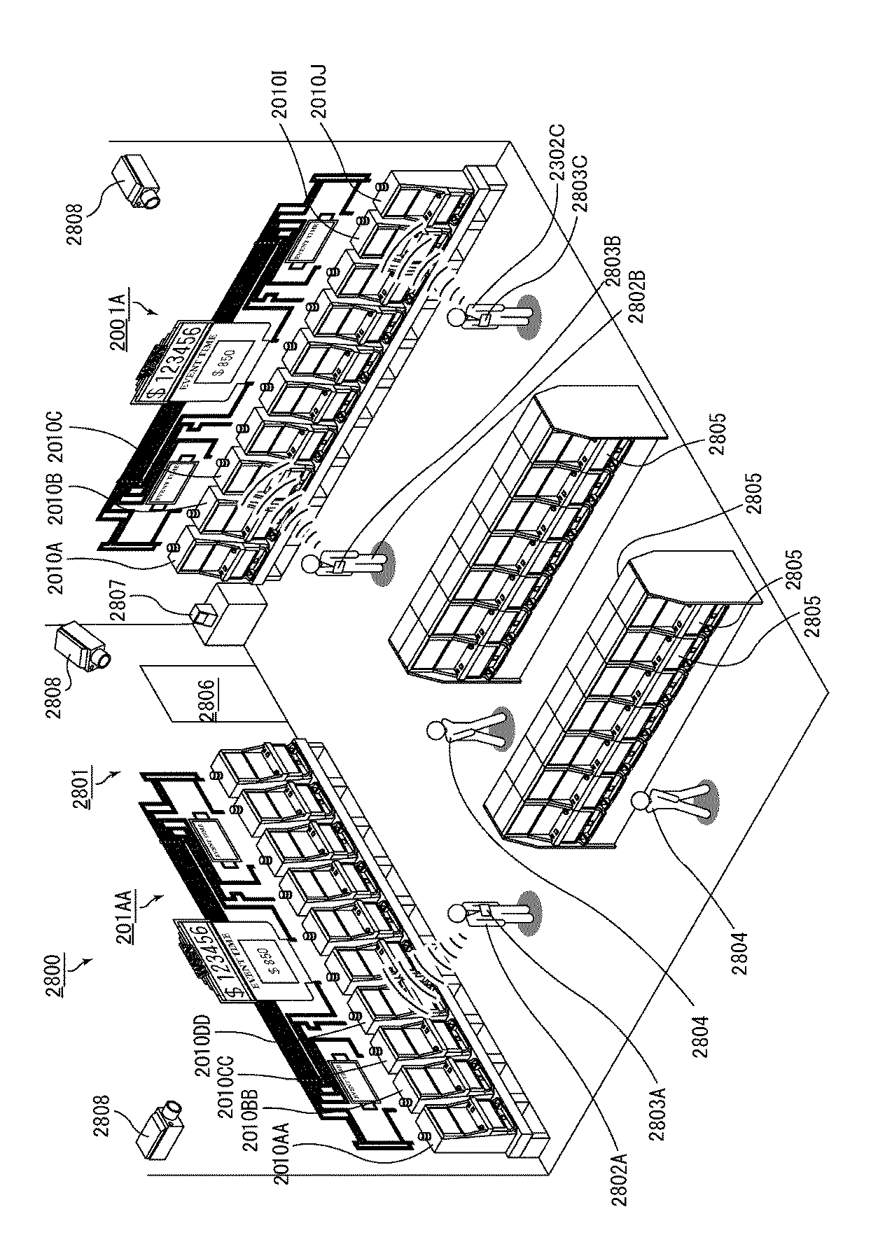
ここで、aは、透過画像における1つの画素に割り当てられている数値、(i,j)は、紙幣の座標であり、座標で所定領域を予め特定しておき、その所定領域の透過画像における画素の総和を導き出す。また、bは、反射画像における1つの画素に割り当てられている数値であり、同様に、所定領域の反射画像における画素の総和を導き出す。 Here, a is a numerical value assigned to one pixel in the transmission image, and (i, j) are the coordinates of the banknote. A predetermined area is specified in advance by the coordinates, and in the transmission image of the predetermined area. Derive the sum of pixels. Further, b is a numerical value assigned to one pixel in the reflection image, and similarly, the sum of pixels in the reflection image of the predetermined area is derived.
上記した数式のように、所定領域において、透過画像における明度の総和(平均値でも良い)が、反射画像のそれ以上となっていれば、その所定領域では透過画像が明るいこととなり、状態変化(水分の付着や孔が開いている)が生じているものとして、その所定領域を除外して、実際の真贋判定処理を実施する。 As in the above mathematical formula, if the total brightness (which may be an average value) in the transmission image is higher than that of the reflection image in the predetermined area, the transmission image is bright in the predetermined area, and the state change ( Assuming that water adheres or has holes, the predetermined area is excluded, and an actual authenticity determination process is performed.
なお、第3の実施の形態では、上記した所定領域は、発光部から異なる波長の光を照射した際に、異なる画素情報が取得される領域(このような領域を特徴領域と称する)以外に設定している。すなわち、発光部(第1発光部3080a及び第2発光部3081b)から異なる波長の光を照射した際に、異なる画素情報が取得される領域については、実際に紙幣の真贋判定を実施するに際しては、重要な部分と考えられることから、これ以外の領域を、上記した所定領域として実際の真贋判定の対象から除外するようにしている。このため、特徴領域において、透過画像における明度の総和(平均値でも良い)が、反射画像のそれ以上となっていても、その特徴部分は、真贋判定処理をするに際して除外されることはない。
In the third embodiment, the predetermined area described above is other than an area where different pixel information is acquired when light having a different wavelength is emitted from the light emitting unit (such an area is referred to as a characteristic area). It is set. That is, when actually deciding the authenticity of a banknote for areas where different pixel information is acquired when light of different wavelengths is irradiated from the light emitting parts (the first
これは、特徴領域でない領域(所定領域)において、上記したような状態変化が生じていても、真贋判定する上で特に影響を与える可能性は低いためであり、このよう特徴領域でない領域を、上述した所定領域に設定することで、真贋判定精度が低下することが防止される。 This is because even if the above-described state change occurs in a region that is not a feature region (predetermined region), there is a low possibility of particularly affecting the authenticity determination. By setting the predetermined area as described above, it is possible to prevent the authentication accuracy from being lowered.
なお、上記した紙幣の特徴領域は、例えば、透かしのような画像が形成されている領域が考えられる。また、紙幣の特徴領域において、水分等が付着していたような場合、すなわち、特徴領域において、透過画像における明度の総和(平均値でも良い)が、反射画像のそれ以上となっていた場合、その紙幣については、直ちに排出処理するようにしても良い。 Note that the above-described banknote feature area may be an area where an image such as a watermark is formed. In addition, in the case where moisture or the like is attached in the feature area of the banknote, that is, in the feature area, the sum of the lightness in the transmission image (may be an average value) is more than that of the reflection image. The banknote may be immediately discharged.
そして、実際の真贋判定処理では、ROM等により、予め記憶されている真正紙幣に関する基準画素データと、搬送される紙幣の表面の印刷領域に発光部(第1発光部3080a及び第2発光部3081b)から所定波長の光を照射し、当該紙幣を透過した光の透過光データ、並びに反射した光の反射光データによる画素データとを比較することで成される。上記したように、その真贋判定処理の前段階で、所定領域において上記した式が満足されていたとしても、それは真正な紙幣に生じている状態変化と判別し、実際の真贋判定処理を実行する際には、その所定領域を除外して、基準データ(予め所定領域を除外した基準データ)との比較処理が実行される。
In the actual authenticity determination processing, the light emitting units (the first
次に、上記した紙幣読取手段3008で真性と識別された紙幣を順次、積層、収容する紙幣収容部3100について説明する。
Next, the
図103から図105に示すように、紙幣収容部3100を構成する本体フレーム3100Aは、略直方体形状に構成されており、その前壁3102aの内側には、付勢手段(付勢バネ)3106の一端が取り付けられ、その他端には、上記した受入口3103を介して送り込まれる紙幣を順次、積層する載置プレート3105が設けられている。このため、載置プレート3105は、前記付勢手段3106を介して、後述する押圧板3115側に向けて付勢された状態になっている。
As shown in FIGS. 103 to 105, the
本体フレーム3100A内には、受入口3103に連続するように、落下する紙幣をそのまま待機、保持させる押圧待機部3108が設けられている。押圧待機部3108の載置プレート側の両サイドには、鉛直方向に延出して一対の規制部材3110が配置されている。この一対の規制部材3110の間には、載置プレート3105上に紙幣が順次、積層されるに際して、押圧板3115が通過するように、開口部が形成されている。
In the
また、本体フレーム3100A内の両サイド壁には、載置プレート3105が付勢手段3106によって押圧された際、載置プレートが当て付くように、突出壁が形成されている。この突出壁は、載置プレート3105上に紙幣が順次、積層されて、前記付勢手段3106によって載置プレートが付勢された際、最上の紙幣の両サイドを当て付け、積層される紙幣を安定して保持する役目を果たす。
In addition, projecting walls are formed on both side walls in the
さらに、本体フレーム3100A内には、受入口3103から押圧待機部3108に落下した紙幣を載置プレート3105に向けて押圧する押圧板3115が配設されている。この押圧板3115は、前記一対の規制部材3110の間に形成された開口部を往復移動できる程度の大きさに構成されており、この開口部内に入り込んで、紙幣を載置プレート3105に押し付ける位置(押圧位置)と、前記押圧待機部3108を開放する位置(初期位置)との間で往復駆動される。この場合、押圧板3115の押し込み動作によって、紙幣は撓みながら開口部を通過して、載置プレート3105上に載置される。
Further, a
前記押圧板3115は、本体フレーム3100A内に配設される押圧板駆動機構3120を介して、上記したように往復駆動される。押圧板駆動機構3120は、押圧板3115を図103及び図104の矢印A方向に往復移動可能となるように、両端が押圧板3115に軸支された一対のリンク部材3115a,3115bを備えており、これらのリンク部材3115a,3115bはX字状に連結され、それぞれの反対側の端部は、垂直方向(矢印B方向)に移動可能に設置された可動部材3122に軸支されている。この可動部材3122には、ラックが形成されており、このラックには、押圧板駆動機構3120を構成するピニオンが噛合している。
The
このピニオンには、図104に示すように、押圧板駆動機構3120を構成する収容部側ギヤトレイン3124が連結されている。この場合、第3の実施の形態においては、図104に示すように、上述した装置本体3002内に、駆動源(モータ3020)と、このモータ3020に順次噛合する本体側ギヤトレイン3021が配設されており、紙幣収容部3100を装置本体3002に装着すると、本体側ギヤトレイン3021が収容部側ギヤトレイン3124に連結するようになっている。すなわち、収容部側ギヤトレイン3124は、ピニオンと同軸上に配設されるギヤ3124B、及びこれに順次噛合するギヤ3124C,3124Dを備えており、紙幣収容部3100を装置本体3002のフレーム3002Aに対して着脱する際、ギヤ3124Dが、本体側ギヤトレイン3021の最終ギヤ3021Aと噛合、離間するよう構成されている。
As shown in FIG. 104, a housing part
この結果、上記した押圧板3115は、装置本体3002に設けられたモータ3020が回転駆動されることで、本体側ギヤトレイン3021、及び押圧板駆動機構3120(収容部側ギヤトレイン3124、可動部材3122に形成されるラック、及びリンク部材3115a,3115b等)を介して、矢印A方向に往復駆動される。
As a result, the above-described
また、本体フレーム3100Aには、前記受入口3103から搬入される紙幣に対して接触可能な搬送部材3150が設置されている。この搬送部材3150は、搬入される紙幣に接触して、安定して紙幣を押圧待機部3108の適正位置(押圧板3115で紙幣を押圧した際、紙幣が左右に片寄ることなく、安定して押圧できる位置)に案内する役目を果たす。第3の実施の形態では、この搬送部材は、押圧待機部3108に臨むように設置されたベルト状の部材(以下、ベルト3150とする)によって構成されている。
The
この場合、ベルト3150は、紙幣に対して搬入方向に沿って延在するように設置されており、搬入方向の両端部に回転可能に支持された一対のプーリ3150A,3150Bに巻回されている。また、ベルト3150は、受入口3103の領域に回転可能に支持された軸方向に延出する搬送ローラ3150Cと当接しており、受入口3103に搬入された紙幣を挟持して、紙幣をそのまま押圧待機部3108に案内するようにしている。さらに、第3の実施の形態では、前記ベルト3150は、紙幣の両サイドの表面に接触可能となるように、上記した押圧板3115を挟むようにして左右一対設けられている。なお、ベルト3150は、両端におけるプーリ3150A,3150Bの巻回以外に、中間位置でテンションプーリを当て付け、弛みを防止するようにしても良い。
In this case, the
前記一対のベルト3150は、装置本体3002内に設置される上述した複数の搬送ローラを駆動するモータ3013によって駆動されるようになっている。具体的には、図105に示すように、モータ3013によって駆動される上述した駆動ベルト3013Bは、駆動力伝達用のプーリ3013Dに巻回されており、このプーリ3013Dに順次設置される動力伝達用のギヤトレイン3013Eには、受入口3103側に回転可能に支持されているプーリ3150Aの支軸の端部に設置されたギヤトレイン3153が噛合するようになっている。すなわち、紙幣収容部3100が装置本体3002に装着された際、ギヤトレイン3013Eの最終ギヤには、ギヤトレイン3153の入力ギヤが噛合するようになっており、一対のベルト3150は、モータ3013の回転駆動により、上述した紙幣搬送用の搬送ローラ3014B,3015B,3016B,3017Bと一体的に回転駆動されるようになっている。
The pair of
上述したように、紙幣が紙幣挿入口3005を介して内部に挿入されると、紙幣は、上記した紙幣搬送機構3006によって、紙幣搬送路3003内で移動して行く。紙幣搬送路3003は、図103に示すように、紙幣挿入口3005から奥側に向けて延出した第1搬送路3003Aと、前記第1搬送路3003Aから下流側に向けて延出し、第1搬送路3003Aに対して所定角度傾斜した第2搬送路3003Bとを備えている。
As described above, when a bill is inserted into the inside via the
そして、この第2搬送路3003Bには、不正行為等により、紙幣を紙幣挿入口3005側に向けて移動するのを防止する引抜防止部材(シャッタ部材)3170が設置されている。この引抜防止部材3170は、支軸3170aを介して、図103の矢印方向(第2搬送路3003Bを閉塞する方向)に回動付勢されており、紙幣が紙幣収容部3100側に向けて移動する際、付勢力に抗して第2搬送路を開放するように回動し、一旦紙幣が通過すると、その付勢力によって、矢印方向に回動され、第2搬送路3003Bを閉塞する。すなわち、紙幣の後端が引抜防止部材3170を通過すると、引抜防止部材3170によって第2搬送路3003Bは閉塞され、紙幣の引抜ができないようになっている。
The
なお、このような引抜防止部材は、紙幣読取手段3008の下流側の搬送経路に沿って、複数箇所設置されていても良い。また、その設置位置に関しては、後述するように、紙幣の真贋判定処理を行っている際に紙幣が停止する位置(エスクロ位置;第3の実施の形態では、紙幣読取手段3008の下流側、約13mmの位置とされる)よりも下流側にあれば良い。
<<<第1の態様の制御手段3200>>>Note that a plurality of such pull-out prevention members may be installed along the conveyance path on the downstream side of the bill reading means 3008. As for the installation position, as will be described later, the position at which the bill stops when the bill authenticity determination process is performed (the escrow position; in the third embodiment, about the downstream side of the bill reading means 3008, about It suffices if it is on the downstream side of the position of 13 mm.
<<<<
次に、上述した紙幣搬送機構3006、紙幣読取手段3008等の駆動部材の駆動を制御する第1の態様の制御手段3200について、図106のブロック図を参照して説明する。
Next, the control means 3200 of the 1st aspect which controls the drive of drive members, such as the
図106のブロック図に示す制御手段3200は、上記した各駆動装置の動作を制御する制御基板3210を備えており、この制御基板3210上には、各駆動装置の駆動を制御すると共に、紙幣識別手段を構成するCPU(Central Processing Unit)3220と、ROM(Read Only Memory)3222と、RAM(Random Access Memory)3224と、真贋判定処理部3230とが実装されている。
The control means 3200 shown in the block diagram of FIG. 106 includes a
前記ROM3222には、紙幣搬送機構用のモータ3013、押圧板駆動用のモータ3020、スキュー補正機構用のモータ3040、ローラ昇降用のモータ3070等、各種駆動装置の作動プログラムや、真贋判定処理部3230における真贋判定プログラム、及び紙幣の先端部分における折れや重送を判定する重送判定プログラムのような各種プログラム等、恒久的なデータが記憶されている。
In the
前記CPU3220は、ROM3222に記憶されている前記プログラムに従って作動して、I/Oポート3240を介して上述した各種駆動装置との信号の入出力を行い、紙幣処理装置の全体的な動作制御を行う。すなわち、CPU3220には、I/Oポート3240を介して、紙幣搬送機構用のモータ3013、押圧板駆動用のモータ3020、スキュー補正機構用のモータ3040、ローラ昇降用のモータ3070が接続されており、これらの駆動装置は、ROM3222に格納された作動プログラムに従って、CPU3220からの制御信号により動作が制御される。また、CPU3220には、I/Oポート3240を介して、挿入検知センサ3007、可動片通過検知センサ3012、排出検知センサ3018からの検知信号が入力されるようになっており、これら検知信号に基づいて、上記した各種駆動装置の駆動制御が行われる。
The
また、CPU3220には、I/Oポート3240を介して、上述した紙幣読取手段3008における受光部3081aから、識別対象物である紙幣に向けて照射された光の透過光や反射光に基づく検知信号が入力されるようになっている。これら紙幣読取手段3008における第1発光部3080a及び第2発光部3081bは、上記したROM3222に格納された動作プログラムに従い、CPU3220からの制御信号によって、発光制御回路3260を介して、点灯間隔、及び消灯が制御される。
In addition, the
さらに、I/Oポート3240には、上述したPTS端末1700に電気的に接続されている。後述するように、紙幣処理装置3001に投入された紙幣の金種を示す金種データと、その紙幣の金額を示す金額データは、I/Oポート3240を介して、PTS端末1700に送信される。
Further, the I /
前記RAM3224には、CPU3220が作動する際に用いるデータやプログラムが一時的に記憶されると共に、識別対象物である紙幣の受光データを取得して一時的に記憶する機能を備えている。また、RAM3224は、受光部3081aで受光した透過光から、後述する変換部3231で変換された複数の画素によって構成される透過画像データ、及び受光部3081aで受光した反射光から変換部3231で変換された複数の画素によって構成される反射画像データを記憶する。
The
前記真贋判定処理部3230は、搬送される紙幣が真正なものであるか否かを判定する機能を有する。この真贋判定処理部3230は、前記RAM3224に格納された識別対象物の受光データに関し、画素毎に、明度を有する色情報(濃度値)を含んだ画素情報に変換する変換部3231と、この変換部3231で変換された画素情報を基にした画像データを取得する画像データ処理部3232と、上述した所定領域における透過画像の画素の明度と、透過画像の所定領域に対応する反射画像の画素の明度とを対比し、その比較結果に基づいて、所定領域を真贋判定の対象から除外する判別部3233とを備えている。このため、前記画像データ処理部3232には、判別部3233において、上述した数式に基づいて、所定領域における透過画像の明度が、同じ所定領域における反射画像の明度よりも高いと判別された場合、その所定領域で得られる透過光による画像データ及び反射光による画像データが除外された状態の画像データが入力される。
The authenticity
また、真贋判定処理部3230は、真正な紙幣に関する基準データ(真正な紙幣に関する画素データ)を格納した基準データ記憶部3234と、前記画像データ処理部3232において取得される紙幣の画像データ(画素データ)と、前記基準データ記憶部3234に格納されている基準データ(基準画素データ)とを比較し、搬送される紙幣が真正であるか否かの判別処理を行う比較判定部3235と、を備えている。
Further, the authenticity
この場合、基準データ記憶部3234には、上記した真贋判定処理を実施するに際して用いられる真正紙幣に関する画像データ、及び上記した所定領域を除外した真正紙幣に関する画像データが記憶されている。すなわち、通常の真贋判定処理では、所定領域の画像データを含んだものが基準データとされるが、判別部3233において、所定領域が除外された場合、その所定領域を除いた画像データが、基準データとして用いられる。また、基準データ記憶部3234には、それ以外にも、例えば、真正紙幣に関する印刷長の基準値等、真贋判定に際して用いられる各種の基準データが金種毎に記憶されている。
In this case, the reference
なお、このような基準となるデータについては、専用の基準データ記憶部3233に記憶させているが、これを上記したROM3222に記憶させておいても良い。
Note that such reference data is stored in the dedicated reference
上記した真贋判定処理部3230における実際の真贋判定処理では、搬送される紙幣の表面の印刷領域に発光部(第1発光部3080a及び第2発光部3081b)から所定波長の光を照射し、当該紙幣を透過した光の透過光データ並びに反射した光の反射光データを、変換部3231において明度を有する色情報を含み所定の大きさを1単位とする複数の画素データに変換し、これを基準データ記憶部3234に予め記憶されている真正紙幣に関する基準画素データと比較することで成される。また、上記したように、紙幣の所定領域で、判別部3233において状態変化があると判別された場合、その所定領域を除いた部分の画像データを取得して真贋判定処理がなされる。
In the actual authenticity determination processing in the authenticity
次に、上述した制御手段3200によって実行される紙幣処理装置3001における紙幣の処理動作について、図107〜図113のフローチャートに従って説明する。
Next, banknote processing operations in the
操作者が紙幣を紙幣挿入口3005に挿入する際、紙幣挿入口の近傍に設置される搬送ローラ対(3014A,3014B)は、初期状態において離間した状態にある(後述するST3016,ST3056参照)。また、押圧板3115は、押圧板3115を駆動する一対のリンク部材3115a,3115bが押圧待機部3108に位置しており、紙幣が一対のリンク部材3115a,3115bによって受入口3103から押圧待機部3108に搬入できない待機位置に設定されている。すなわち、この状態では、一対の規制部材3110の間に形成された開口部に押圧板3115が入り込んでいるため、開口部を介して紙幣収容部内に収容されている紙幣を抜き取ることができない状態となっている。
When the operator inserts a banknote into the
さらに、搬送ローラ対(3014A,3014B)の下流側に位置するスキュー補正機構3010を構成する一対の可動片3010Aは、初期状態において、あらゆる紙幣の引き抜きができないように最小幅(例えば一対の可動片3010Aの間隔が52mm;後述するST3015,ST3057参照)に移動した状態にある。
Further, the pair of
上記した搬送ローラ対(3014A,3014B)の初期状態では、皺のある紙幣であっても、操作者は容易に挿入することができる。そして、挿入検知センサ3007によって紙幣の挿入が検知されると(ST3001)、上述した押圧板3115の駆動用のモータ3020を所定量逆転駆動し(ST3002)、押圧板3115を初期位置に移動させる。すなわち、挿入検知センサ3007によって紙幣の挿入が検知されるまでは、前記押圧板3115は、一対の規制部材3110の間に形成された開口部に移動された状態となっており、開口部を介して紙幣が通過できないように設定されている。
In the initial state of the transport roller pair (3014A, 3014B) described above, the operator can easily insert even a banknote with a hook. When insertion of a bill is detected by the insertion detection sensor 3007 (ST3001), the
押圧板3115が待機位置から初期位置に移動されると、押圧待機部3108は開放状態となり(図104参照)、紙幣は、紙幣収容部3100内に搬入可能な状態となる。すなわち、モータ3020を所定量逆転駆動することで、押圧板3115は、本体側ギヤトレイン3021、及び押圧板駆動機構3120(収容部側ギヤトレイン3124、可動部材3122に形成されるラック、及びリンク部材3115a,3115b)を介して、前記待機位置から初期位置に移動される。
When the
また、上述したローラ昇降用モータ3070を駆動し、上側の搬送ローラ3014Aを下側の搬送ローラ3014Bに当接するように移動させる。これにより、挿入された紙幣は搬送ローラ対(3014A,3014B)によって挟持される(ST3003)。
Further, the above-described roller raising / lowering
次いで、紙幣搬送路の開放処理が成される(ST3004)。この開放処理は、図110に示すフローチャートに示すように、述したスキュー補正機構用のモータ3040を逆転駆動することで、一対の可動片3010Aを互いに離間する方向に駆動することで成される(ST3100)。このとき、一対の可動片3010Aの位置を検知する可動片検知センサによって、一対の可動片3010Aが所定位置(最大幅位置)に移動したことが検知されると(ST3101)、モータ3040の逆転駆動が停止される(ST3102)。この搬送路開放処理により、一対の可動片3010A内に紙幣が進入できる状態になっている。なお、このST3004の前段階では、紙幣搬送路3003は、後述する搬送路閉鎖処理(ST3015,ST3057)によって閉鎖された状態にあるが、このように、紙幣挿入前に紙幣搬送路3003を閉じておくことで、例えば、不正目的などで紙幣挿入口から板状の部材を挿入して、ラインセンサなどの素子を破損させることを防止することができる。
Subsequently, the banknote conveyance path opening process is performed (ST3004). As shown in the flowchart shown in FIG. 110, this release process is performed by driving the pair of
次いで、紙幣搬送用のモータ3013が正転駆動される(ST3005)。紙幣は、搬送ローラ対(3014A,3014B)によって装置内部に搬送され、スキュー補正機構3010よりも下流側に配設されている可動片通過検知センサ3012が紙幣の先端を検知すると、紙幣搬送用のモータ3013は停止される(ST3006,ST3007)。このとき、紙幣は、スキュー補正機構3010を構成する一対の可動片3010A間に位置している。
Next, the
引き続き、上述したローラ昇降用モータ3070を駆動し、紙幣を挟持した状態となっている搬送ローラ対(3014A,3014B)を離間させる(ST3008)。このとき、紙幣には、何等、負荷が作用していない状態となる。
Subsequently, the roller raising / lowering
そして、この状態でスキュー補正作動処理を行う(ST3009)。このスキュー補正作動処理は、上述したスキュー補正機構用のモータ3040を正転駆動することで、一対の可動片3010Aを互いに接近する方向に駆動することで成される。すなわち、このスキュー補正作動処理は、図111のフローチャートに示すように、上述したモータ3040を正転駆動することで、一対の可動片3010Aを、互いに接近する方向に移動する(ST3110)。この可動片の移動は、制御手段における基準データ記憶部に登録されている紙幣の最小幅(例;幅62mm)となるまで実行され、これにより、紙幣は、両側に当て付く可動片3010Aによって、スキューが補正され、正確な中心位置となるように位置決めされる。
In this state, skew correction operation processing is performed (ST3009). This skew correction operation process is performed by driving the pair of
上述したようなスキュー補正作動処理が終了すると、引き続き、搬送路開放処理が実行される(ST3010)。これは、上述したスキュー補正機構用のモータ3040を逆転駆動することで、一対の可動片3010Aを離間する方向に移動することで成される(図110のST3100〜ST3102参照)。
When the skew correction operation process as described above is completed, the conveyance path opening process is subsequently executed (ST3010). This is achieved by moving the pair of
続いて、上述したローラ昇降用モータ3070を駆動し、上側の搬送ローラ3014Aを下側の搬送ローラ3014Bに当接するように移動させ、紙幣を搬送ローラ対(3014A,3014B)に挟持させる(ST3011)。その後、紙幣搬送用のモータ3013を正転駆動して紙幣を装置内部に向けて搬送し、紙幣が紙幣読取手段3008を通過する際に、紙幣の読取処理を開始する(ST3012,ST3013)。
Subsequently, the roller raising / lowering
そして、搬送される紙幣が紙幣読取手段3008を通過して、紙幣の後端が、可動片通過検知センサ3012によって検知されると(ST3014)、紙幣搬送路3003の閉鎖処理が実行される(ST3015)。この処理においては、まず、図112のフローチャートに示すように、紙幣の後端が、可動片通過検知センサ3012によって検知された後、上述したモータ3040を正転駆動することで、一対の可動片3010Aを、互いに接近する方向に移動する(ST3130)。次に、可動片検知センサによって、可動片3010Aが所定位置(最小幅位置、例えば52mm)に移動したことが検知されると(ST3131)、モータ3040の正転駆動が停止される(ST3132)。
When the bill to be conveyed passes through the bill reading means 3008 and the trailing end of the bill is detected by the movable piece passage detection sensor 3012 (ST3014), the closing processing of the
この搬送路閉鎖処理により、一対の可動片3010Aは、挿入可能なあらゆる紙幣の幅よりも狭い最小幅位置(幅52mm)に移動されており、これにより、紙幣の引き抜きを効果的に防止するようにしている。すなわち、このような紙幣搬送路の閉鎖処理を実行することで、挿入された紙幣の幅よりも、可動片3010A間の距離が狭くなり、操作者が不正目的で紙幣を挿入口方向に向けて引き抜く等の行為を効果的に防止することが可能となる。
By this conveyance path closing process, the pair of
上記した搬送路閉鎖処理(ST3015)に引き続いて、上述したローラ昇降用モータ3070を駆動し、紙幣を挟持可能な状態となっている搬送ローラ対(3014A,3014B)を離間させる搬送ローラ対離間処理が行われる(ST3016)。この搬送ローラ対離間処理を行うことで、操作者が誤って紙幣を追加投入(二重投入)しても、紙幣は、搬送ローラ対(3014A,3014B)による送り動作を受けることはなく、また、ST3015において接近した状態にある一対の可動片3010Aの前面に突き当たることから、紙幣の二重投入動作を確実に防止することができる。
Subsequent to the above-described transport path closing process (ST3015), the roller lifting / lowering
上記した紙幣搬送路の閉鎖処理と共に、紙幣読取手段3008が紙幣の後端までデータを読取ると、紙幣搬送用のモータ3013を所定量駆動し、紙幣を所定位置(エスクロ位置;紙幣読取手段3008の中心位置から13mm紙幣が下流側に搬送された位置)で停止させ、このときに、制御手段3200の真贋判定処理部3230において、基準データ記憶部3234に記憶されている基準データを参照し、比較判定部3235で紙幣の真贋判定処理を実行する(ST3017〜ST3020)。
When the banknote reading means 3008 reads data to the rear end of the banknote together with the above-described banknote transport path closing process, the
この真贋判定処理においては、まず、図113のフローチャートに示すように、判別部3233において、紙幣の所定領域における透過画像の画素の明度と、透過画像の所定領域に対応する反射画像の画素の明度とを対比し、所定領域に状態変化があるかないかを判別する(ST3150)。この判別は、上述した数式に基づいて、所定領域における透過画像の明度の総和と、同じ所定領域における反射画像の明度の総和とを比較することで行われる。そして、状態変化がないと判別された場合、画像データ処理部3232は、その所定領域を含んだ画像データを取得し、比較判定部3235において、基準データ記憶部3234に記憶された基準データと比較処理を行う(ST3152)。一方、判別部3233において、所定領域に状態変化があると判別された場合、画像データ処理部3232は、その所定領域を除いた画像データを取得し(ST3151)、比較判定部3235において、基準データ記憶部3234に記憶された基準データ(所定領域を除いた基準データ)と比較処理を行う(ST3152)。
In this authenticity determination process, first, as shown in the flowchart of FIG. 113, in the
上述したST3152における比較処理において、投入された紙幣が真券であると判別したときにときには、投入された紙幣の金種を示す金種データと金額を示す金額データとを、紙幣読取手段3008で読み取った画像データを用いて、文字認識などの処理を施すことによって取得し、取得した金種データと金額データとをRAM3224に記憶させる。これらの情報は、後述するように、PTS端末1700に送信される。
When it is determined in the comparison process in ST3152 that the inserted banknote is a genuine note, the denomination data indicating the denomination of the inserted banknote and the money amount data indicating the amount are displayed by the
そして、上記したST3020の真贋判定処理において、紙幣が真券であると判定されると(ST3021;Yes)、紙幣搬送用のモータ3013を正転駆動する(ST3022)。この紙幣の搬送に際しては、紙幣の後端が排出検知センサ3018によって検知されるまで紙幣搬送用のモータ3013は正転駆動され(ST3023)、紙幣の後端が排出検知センサ3018によって検知されてから、紙幣搬送用のモータ3013は所定量だけ正転駆動される(ST3024,ST3025)。
In the authenticity determination process of ST3020 described above, when it is determined that the bill is a genuine note (ST3021; Yes), the
このST3024、及びST3025における紙幣搬送用のモータ3013の正転駆動処理は、紙幣が、装置本体3002の紙幣搬送路3003の下流側にある排出口3003aから紙幣収容部3100の受入口3103に搬入され、前記一対のベルト3150が、搬入される紙幣の両側表面に接触して安定して、押圧待機部3108に案内される駆動量に対応している。すなわち、紙幣の後端が排出検知センサ3018によって検知された後、更に、所定量、紙幣搬送用のモータ3013を正転駆動することで、前記一対のベルト3150は、搬入される紙幣に接触しつつ紙幣送り方向に駆動され、紙幣を安定した状態で押圧待機部3108に案内する。
In the normal rotation driving process of the
そして、上記した紙幣搬送用のモータ3013が停止した後、紙幣を載置プレート3105上に載置すべく押圧板3115の駆動処理を実行し(ST3026)、押圧処理が終了すると、押圧板3115は再び待機位置に移動され、その位置で停止される。
Then, after the
また、上述した処理手順のST3021において、挿入された紙幣が真券でないと判別された場合、搬送路開放処理を実行し(ST3051、図110のST3100〜ST3102参照)、その後、紙幣搬送用のモータ3013を逆転駆動し、搬送ローラ対(3014A,3014B)の挟持処理を実行した後、エスクロ位置に待機している紙幣を、紙幣挿入口3005に向けて搬送する(ST3052,ST3053)。そして、挿入検知センサ3007が、紙幣挿入口3005に向けて差し戻される紙幣の後端を検知した際に、紙幣搬送用のモータ3013の逆転駆動を停止すると共に、上述したローラ昇降用モータ3070を駆動し、紙幣を挟持した状態となっている搬送ローラ対(3014A,3014B)を離間させる(ST3054〜ST3056)。その後、搬送路閉鎖処理を実施(ST3057,図112のST3130〜ST3132参照)すると共に、押圧板3115の駆動用のモータ3020を所定量正転駆動することで(ST3058)、初期位置にある押圧板3115を待機位置に駆動する。
If it is determined in ST3021 of the above-described processing procedure that the inserted banknote is not a genuine note, a transport path opening process is executed (see ST3051, ST3100 to ST3102 in FIG. 110), and then a banknote transport motor. After reversely driving 3013 and carrying out the holding process of the pair of conveyance rollers (3014A, 3014B), the banknote waiting at the escrow position is conveyed toward the banknote insertion slot 3005 (ST3052, ST3053). Then, when the
上述したST3026の処理又はST3058の処理を実行した後、図114に示す情報出力処理のサブルーチンを呼び出して実行する(ST3070)。 After executing the above-described processing of ST3026 or ST3058, the information output processing subroutine shown in FIG. 114 is called and executed (ST3070).
図114は、PTS端末1700に各種の情報を出力する処理のサブルーチン示すフローチャートである。
FIG. 114 is a flowchart showing a subroutine of processing for outputting various types of information to the
最初に、紙幣の真贋判定の結果が真券であるか否かを判断する(ステップST3071)。紙幣の真贋判定の結果は、上述した図113に示したサブルーチンを実行することによって得ることができる。 First, it is determined whether or not the result of bill authenticity determination is a genuine note (step ST3071). The result of bill authenticity determination can be obtained by executing the subroutine shown in FIG. 113 described above.
紙幣の真贋判定の結果が真券であると判別したとき(YES)には、紙幣の金種を示す金種データと、金額を示す金額データとを、I/Oポート3240を介して、PTS端末1700に出力し(ステップST3072)、本サブルーチンを終了する。ここで、紙幣の金種とは、USドル紙幣や円紙幣や香港ドル紙幣などの紙幣を発行したり管理したりする国や政府や中央銀行や地域などを含む紙幣の属性を示す紙幣属性情報からなる。また、金額は、その紙幣の属性によって定まる通貨単位に対応した金額である。通貨単位は、例えば、USドルや円などがある。
When it is determined that the result of the authenticity determination of the bill is a genuine note (YES), the denomination data indicating the denomination of the bill and the amount data indicating the amount of money are sent via the I /
紙幣の真贋判定の結果が偽券であると判別したとき(NO)には、投入された紙幣が偽券であることを示すエラー情報を、I/Oポート3240を介して、PTS端末1700に出力し(ステップST3073)、本サブルーチンを終了する。
When it is determined that the bill authenticity determination result is a fake note (NO), error information indicating that the inserted bill is a fake note is sent to the
このように、金種を示す金種データと金額を示す金額データとをPTS端末1700に送信することによって、PTS端末1700は、紙幣処理装置3001に投入された紙幣の金種データと金額データとを取得することができ、これらのデータに基づいて、クレジットの変換や、そのときにおける為替レートに応じた両替などの各種の処理を実行することができる。
In this manner, by transmitting denomination data indicating the denomination and amount data indicating the amount of money to the
上記した構成の紙幣処理装置によれば、真正な紙幣であるにもかかわらず、所定領域に状態変化があるような紙幣が挿入された場合、まず、判別部において、その状態変化(主に水分を含んでいるものや孔等の欠損があるもの)があるか否かを判別し、所定領域に状態変化があれば、その所定領域を真贋判定の対象から除外するようにしている。従って、真正な紙幣であっても、その状態変化が原因で偽券と判定される可能性が少なくなり、真贋判定精度の向上を図ることが可能となる。 According to the banknote handling apparatus having the above-described configuration, when a banknote having a state change in a predetermined area is inserted even though it is a genuine banknote, first, in the determination unit, the state change (mainly moisture) In the case where there is a change in the state of the predetermined area, the predetermined area is excluded from the objects of authenticity determination. Therefore, even if it is a genuine banknote, the possibility that it is determined to be a fake note due to its state change is reduced, and it is possible to improve the accuracy of authenticity determination.
特に、カジノなどの遊技場では、プレイの間に、プレーヤは、飲食をする場合もある。このような飲食をした場合に、飲み物や食べ物で紙幣を汚してしまうことも想定される。このような汚れた紙幣は、真券であるにも拘わらず、偽券であると判別されてしまった場合には、プレーヤに迷惑をかけるだけでなく、遊技場の処理も煩雑になる。上述した紙幣処理装置3001は、状態変化が原因で偽券と判定される可能性を少なくできるので、プレーヤに迷惑をかけたり、遊技場の対応が煩雑になったりすることを防止できる。この紙幣処理装置3001は、遊技媒体貸出機や自動販売機や券売機等に搭載するだけでなく、遊技機に搭載することもできる。
In particular, in a game arcade such as a casino, a player may eat and drink during play. When such eating and drinking is performed, it is also assumed that the banknotes are soiled with drinks and food. If such a dirty bill is a genuine note but has been determined to be a fake note, it not only inconveniences the player but also complicates the processing of the game hall. The
特に、第3の実施の形態では、紙幣の所定領域は、紙幣読取手段を構成する発光部から、異なる波長の光を照射した際に異なる画素情報が取得される特徴領域(紙幣の真贋を判定する上では重要となる領域)以外に設定しており、所定領域において上記したような状態変化が生じていても、真贋判定する上で影響を与える可能性は低くなり、真贋判定精度が低下することが防止される。 In particular, in the third embodiment, the predetermined area of the banknote is a characteristic area (determining the authenticity of the banknote) in which different pixel information is acquired when light of different wavelengths is emitted from the light emitting unit constituting the banknote reading means. In this case, even if the above-described state change occurs in a predetermined area, the possibility of affecting the authenticity determination is reduced, and the authenticity determination accuracy is lowered. It is prevented.
また、上記した第3の実施の形態では、受光部は、紙幣の幅方向全体の範囲を読取るラインセンサによって構成されているため、上記した所定領域や特徴領域を正確に特定することが可能となり、真贋判定精度をより向上することが可能となる。 Further, in the above-described third embodiment, since the light receiving unit is configured by a line sensor that reads the entire range of the banknote in the width direction, it is possible to accurately specify the above-described predetermined area and characteristic area. Therefore, it is possible to further improve the accuracy of authenticity determination.
以上、本発明の実施形態について説明したが、本発明は、上記した実施形態に限定されることなく、種々変形して実施することが可能である。 As mentioned above, although embodiment of this invention was described, this invention is not limited to above-described embodiment, It is possible to implement various deformation | transformation.
例えば、状態変化が生じていた際に真贋判定から除外される所定領域については、紙幣上、複数箇所に設けておいても良いし、その面積についても適宜変形することが可能である。また、本発明は、紙幣の真贋判定処理において、所定領域に状態変化があった際、その所定領域を除外して真贋判定処理を行うことに特徴があり、それ以外の構成については、第3の実施の形態に限定されることはなく、種々変形することが可能である。例えば、紙幣の読取手段3008の構成、配設位置等については、適宜、変形することが可能である。 For example, the predetermined area that is excluded from the authenticity determination when the state change has occurred may be provided at a plurality of locations on the banknote, and the area thereof can be appropriately modified. In addition, the present invention is characterized in that, in a bill authenticity determination process, when a predetermined area changes, the authenticity determination process is performed by excluding the predetermined area. The present invention is not limited to this embodiment, and various modifications can be made. For example, the configuration and arrangement position of the bill reading means 3008 can be modified as appropriate.
本発明は、紙幣処理装置に限定されることはなく、クーポン券やサービス券など、紙葉類が挿入されたことで、各種の商品やサービスを提供する装置に組み込むことが可能である。
<<<第2の態様の制御手段3200>>>The present invention is not limited to a banknote processing apparatus, and can be incorporated into an apparatus that provides various products and services by inserting paper sheets such as coupons and service tickets.
<<<
次に、上述した紙幣搬送機構3006、紙幣読取手段3008等の駆動部材の駆動を制御する制御手段3200について、図116のブロック図を参照して説明する。
Next, the control means 3200 for controlling the driving of driving members such as the above-described
図116のブロック図に示す制御手段3200は、上記した各駆動装置の動作を制御する制御基板3210を備えており、この制御基板3210上には、各駆動装置の駆動を制御すると共に、紙幣識別手段を構成するCPU(Central Processing Unit)3220と、ROM(Read Only Memory)3222と、RAM(Random Access Memory)3224と、紙幣判別処理部3230とが実装されている。
The control means 3200 shown in the block diagram of FIG. 116 includes a
前記ROM3222には、紙幣搬送機構用のモータ3013、押圧板駆動用のモータ3020、スキュー補正機構用のモータ3040、ローラ昇降用のモータ3070等、各種駆動装置の作動プログラムや、真贋判定部3230における真贋判定プログラム、及び紙幣の損傷を判別する紙幣損傷判別プログラムのような各種プログラム等、恒久的なデータが記憶されている。
In the
前記CPU3220は、ROM3222に記憶されている前記プログラムに従って作動して、I/Oポート3240を介して上述した各種駆動装置との信号の入出力を行い、紙幣処理装置の全体的な動作制御を行う。すなわち、CPU3220には、I/Oポート3240を介して、紙幣搬送機構用のモータ3013、押圧板駆動用のモータ3020、スキュー補正機構用のモータ3040、ローラ昇降用のモータ3070が接続されており、これらの駆動装置は、ROM3222に格納された作動プログラムに従って、CPU3220からの制御信号により動作が制御される。また、CPU3220には、I/Oポート3240を介して、挿入検知センサ3007、可動片通過検知センサ3012、排出検知センサ3018からの検知信号が入力されるようになっており、これら検知信号に基づいて、上記した各種駆動装置の駆動制御が行われる。
The
さらに、CPU3220には、I/Oポート3240を介して、上述した紙幣読取手段3008における受光部3081aから、識別対象物に照射された光の透過光や反射光に基づく検知信号が入力されるようになっている。
Further, the
さらにまた、I/Oポート3240には、上述したPTS端末1700に電気的に接続されている。後述するように、紙幣処理装置3001に投入された紙幣の金種データと金額データとは、I/Oポート3240を介して、PTS端末1700に送信される。
Furthermore, the I /
前記RAM3224には、CPU3220が作動する際に用いるデータやプログラムが一時的に記憶されると共に、識別対象物である紙幣の受光データ(複数の画素によって構成される画像データ)を取得して一時的に記憶する機能を備えている。
The
前記紙幣判別処理部3230は、搬送される紙幣の先端が欠けている等の損傷を判別する損傷判別処理、及び、損傷が生じていない紙幣について、それが真正なものであるか否かを判定する真贋判定処理を実施する機能を有する。この紙幣判別処理部3230は、前記RAM3224に格納された識別対象物の受光データに関し、画素毎に、明るさを有する色情報(濃度値)を含んだ画素情報に変換する変換部3231と、この変換部3231で変換された画素情報を基に、例えばエッジ情報を取得して、搬送された紙幣の先端形状を特定するデータ処理部3232とを有する。
The bill discriminating
また、前記紙幣判別処理部3230は、搬送される紙幣の先端が折れ曲がっていたり、欠けている等の損傷を判別する損傷判別処理、及び、損傷が生じていない紙幣について、それが真正なものであるか否かを判定する真贋判定処理を実施する機能を有する。この紙幣判別処理部3230は、前記RAM3224に格納された識別対象物の受光データに関し、画素毎に、明るさを有する色情報(濃度値)を含んだ画素情報に変換する変換部3231と、この変換部3231で変換された画素情報を基に、例えばエッジ情報を取得して、搬送された紙幣の先端形状を特定するデータ処理部3232とを有する。
Further, the bill discriminating
また、紙幣判別処理部3230は、真正な紙幣に関する基準データ(真正な紙幣に関する
形状データ)を格納した基準データ記憶部3234と、前記データ処理部3232において特定された判別対象となる紙幣の形状データと基準データ記憶部3234に格納されている基準データとを比較し、搬送される紙幣に損傷があるか否かの判別処理を行う比較判定部3235と、を備えている。Also, the bill
なお、基準データ記憶部3234には、更に、上記した真贋判定処理を実施するに際して用いられる真正紙幣に関する画像データや、真正紙幣に関する印刷長の基準値等、真贋判定に際して用いられる各種の基準データが金種毎に記憶されている。この場合、上記した基準データについては、専用の基準データ記憶部3234に記憶させているが、これを上記したROM3222に記憶させておいても良い。
The reference
さらに、CPU3220には、I/Oポート3240を介して、上述した紙幣読取手段3008における第1発光部3080aと、第2発光部3081bが接続されている。これら第1発光部3080a及び第2発光部3081bは、上記したROM3222に格納された動作プログラムに従い、CPU3220からの制御信号によって、発光制御回路3260を介して、点灯間隔、及び消灯が制御される。
Further, the
<<損傷の判断手法(第1の損傷の判断手法及び第2の損傷の判断手法)>>
ここで、図117に示すような、紙幣先端部分に欠けのある紙幣Mが挿入された場合について説明する。<< Damage Determination Method (First Damage Determination Method and Second Damage Determination Method) >>
Here, the case where the banknote M with a chip | tip in a banknote front-end | tip part as shown in FIG. 117 is inserted is demonstrated.
上記したように、紙幣読取手段3008は、紙幣搬送機構3006によって搬送された紙幣に対し、前記第1発光部3080a、及び第2発光部3081bから光(赤色光、赤外光)を照射し、その透過光や反射光を受光部(ラインセンサ)3081aで受光して紙幣の読取りを実行する。この読取りに際しては、紙幣の搬送処理が行われている間、所定の大きさを1単位(例えば、搬送方向における1ピクセルが0.508mm)とする多数の画素情報を取得することが可能であり、このようにして取得された多数の画素(複数の画素)によって構成される画像データは、RAM3224などの記憶手段に記憶される。なお、ここで記憶される多数の画素によって構成される画像データは、変換部3231によって、画素毎に、明るさを有する色情報(濃度値に応じて0から255の数値(0:黒〜255:白)が割り当てられた色情報)を含んだ情報に変換される。
As described above, the
<第1の損傷の判断手法>
この場合、搬送される紙幣Mの先端の隅に欠けMaがあるような紙幣が挿入されて、これが紙幣読取手段3008を通過すると、紙幣の幅方向に亘って配設されるCCDラインセンサを有する受光部3081aによって、その欠けMaの形状を具体的に取得することが可能である。これは、例えば、受光部3081aにおいて受光する透過光データでは、欠けMaの部分を透過する透過光の受光量が大きくなること、或いは、反射光データでは、欠けMaの部分から反射光が得られないこと等から、前記変換部3231で変換される画素情報によって、搬送される紙幣Mの具体的なエッジ形状(欠けMaのあるエッジ形状)のデータを取得することが可能となる。<First damage determination method>
In this case, when a bill having a chip Ma at the corner of the leading end of the bill M to be conveyed is inserted and passes through the bill reading means 3008, it has a CCD line sensor disposed across the width direction of the bill. The shape of the chipped Ma can be specifically acquired by the
そして、取得されたエッジ形状のデータと、基準データ記憶部3234に格納されている基準データ(欠けのない紙幣のエッジ形状のデータ)とを比較判定部3235で対比し、その類似度が高いものについては、欠けが生じていない紙幣と判別し、そうでないものについては、欠けが生じている紙幣と判別する。
Then, the acquired edge shape data is compared with the reference data stored in the reference data storage unit 3234 (the edge shape data of the banknote without a chip) by the
この場合、類似度の判別の手法については、特に限定されることはないが、例えば、エッジ情報を取得した後、そのエッジ内に含まれる画素数を対比して、所定の閾値以上あるものは、類似(欠けのない紙幣)と判別し、閾値未満のものについては、類似しない(欠けが生じている紙幣)と判別するようにしても良い。 In this case, the method of determining the similarity is not particularly limited. For example, after acquiring edge information, the number of pixels included in the edge is compared, and those having a predetermined threshold value or more are compared. It may be determined that the banknotes are similar (banknotes with no chipping), and those that are less than the threshold are determined not to be similar (banknotes with chipping).
また、このような欠けが生じているか否かの判別については、紙幣読取手段3008による紙幣の読取りが終了する前までに実行される。第3の実施の形態では、搬送される紙幣Mの先端M1から所定の範囲R(例えば、20mmに設定される)読取った段階で、上記した判別処理を実行するようにしており、判別処理が終了するまでには、少なくとも、紙幣は紙幣読取手段3008を通過しないように設定されている。そして、上記したCPU3220は、紙幣に欠け等の損傷が生じていると判別された場合、紙幣搬送機構用モータ3013を逆転駆動し、挿入された紙幣を、そのまま紙幣挿入口3005から排出するようにしている。
Further, the determination of whether or not such a chip has occurred is performed before the
<<第2の損傷の判断手法>>
通常、紙幣は、図118(a)に示すように、裁断工程等を考慮して、印刷領域3300の周囲に非印刷領域3301が形成された構成となっている。この非印刷領域3301は、インクが付着していない領域であることから、透過光を受光部3081aにおいて取得すると、印刷領域3300と比較して、ラインP1を境にして画素毎の濃度値は高い値が得られるようになる。<< Second Damage Determination Method >>
Normally, as shown in FIG. 118A, the banknote has a configuration in which a
ところが、紙幣の先端M1部分が、例えば図118(b)に示すように内側に折れ曲がっていると、その部分における透過光Raは、折れ曲がった部分を通過することで、その透過光量Ra´が図118(a)で示すものよりも弱くなってしまい、これにより、透過光を受光部3081aにおいて取得すると、通常の透過光量よりもかなり暗い状態となる。すなわち、通常の折れが生じていない紙幣と比較すると、その先端領域で得られる画素毎の濃度値は低くなってしまう。
However, if the leading edge M1 portion of the banknote is bent inward as shown in FIG. 118 (b), for example, the transmitted light Ra at that portion passes through the bent portion, so that the transmitted light amount Ra 'is illustrated. As a result, when the transmitted light is acquired by the
このため、紙幣の幅方向に亘って配設されるCCDラインセンサを有する受光部3081aによって、搬送される紙幣の先端部分の読取りを実行する際、変換部3231で変換される画素情報によって、搬送される紙幣Mに折れが生じているか否かを判別することが可能となる。例えば、取得された紙幣Mの先端領域における画素データの幅方向の合計値と、基準データ記憶部3234に格納されている基準データ(図118(a)のように先端部分で折れが生じていない非印刷領域3301の画素データの合計値)とを、比較判定部3235で対比し、合計濃度値が所定の閾値より高いものについては、折れが生じていない紙幣と判別し、合計濃度値が所定の閾値より低いものについては、折れが生じている紙幣と判別する。
For this reason, when reading the front-end | tip part of the banknote conveyed by the light-receiving
図118(b)で示すように、紙幣の先端M1部分に折れが生じていた場合、その部分が上述した引抜防止部材3170を通過する際、特に、通過した後に真贋判定処理で真正と判別されず逆搬送されると、折れ部分が引抜防止部材3170に引っ掛かってしまい搬送トラブルが生じる可能性があるが、そのような折れが生じている紙幣を紙幣読取手段3008において検出し、紙幣搬送機構3006を制御することで、そのような搬送トラブルを未然に防止することが可能となる。
As shown in FIG. 118 (b), when the leading edge M1 portion of the banknote is folded, when the portion passes through the pull-out preventing
また、第3の実施の形態では、図118(c)に示すように、搬送される紙幣Mの先端の隅に欠けMaがあるような紙幣が挿入されて、これが紙幣読取手段3008を通過すると、紙幣の幅方向に亘って配設されるCCDラインセンサを有する受光部3081aによって、その欠けMaの形状を具体的に取得することが可能となっている。
Moreover, in 3rd Embodiment, as shown in FIG.118 (c), when the banknote with a chip | corner Ma is inserted in the corner of the front-end | tip of the banknote M conveyed, when this passes the banknote reading means 3008, it will be. The shape of the chipped Ma can be specifically acquired by the
これは、例えば、受光部3081aにおいて受光する透過光データでは、欠けMaの部分を透過する透過光の受光量が大きくなること、或いは、反射光データでは、欠けMaの部分から反射光が得られないこと等から、前記変換部3231で変換される画素情報によって、搬送される紙幣Mの具体的なエッジ形状(欠けMaのあるエッジ形状)のデータを取得することが可能となる。そして、取得されたエッジ形状のデータと、基準データ記憶部3234に格納されている基準データ(欠けのない紙幣のエッジ形状のデータ)とを比較判定部3235で対比し、その類似度が高いものについては、欠けが生じていない紙幣と判別し、そうでないものについては、欠けが生じている紙幣と判別するようにしている。
This is because, for example, in the transmitted light data received by the
この第2の損傷の判断手法の場合も、類似度の判別の手法については、特に限定されることはないが、例えば、エッジ情報を取得した後、そのエッジ内に含まれる画素数を対比して、所定の閾値以上あるものは、類似(欠けのない紙幣)と判別し、閾値未満のものについては、類似しない(欠けが生じている紙幣)と判別するようにしても良い。 In the second damage determination method, the similarity determination method is not particularly limited. For example, after acquiring edge information, the number of pixels included in the edge is compared. Thus, it may be determined that those having a predetermined threshold value or more are similar (banknotes having no chip), and those having a threshold value less than the threshold value are determined not to be similar (banknotes having a chip).
上記したように、折れや欠けが生じているか否かの判別については、紙幣読取手段3008による紙幣の読取りが終了する前までに実行される。第3の実施の形態では、搬送される紙幣Mの先端M1から所定の範囲R(例えば、20mmに設定される)読取った段階で、上記した判別処理を実行するようにしており、判別処理が終了するまでには、少なくとも、紙幣は紙幣読取手段3008を通過しないように設定されている。そして、上記したCPU3220は、紙幣に欠け等の損傷が生じていると判別された場合、紙幣搬送機構用モータ3013を逆転駆動し、挿入された紙幣を、そのまま紙幣挿入口3005から排出するようにしている。
As described above, whether or not a fold or a chip has occurred is determined before the
なお、上記した紙幣の第1の損傷の判断手法又は第2の損傷の判断手法については、遅くとも、紙幣の先端が、上述した引抜防止部材3170を通過する前までに実行されていれば良く、このように設定することにより、紙幣を逆搬送する際に、引っ掛かりが生じることを確実に防止することが可能となる。また、引抜防止部材3170が、搬送方向に沿って複数箇所設置されている構成では、最も上流に設置された引抜防止部材を通過する前までに実行されていれば良い。
In addition, about the judgment method of the above-mentioned 1st damage of a banknote, or the 2nd damage judgment technique, what is necessary is just to be performed before the front-end | tip of a banknote passes the above-mentioned
<<損傷の判別処理>>
次に、上述した制御手段3200によって実行される紙幣処理装置3001における紙幣の処理動作について、図107、図119、図120、図110〜図112、図121及び図122のフローチャートに従って説明する。なお、上述した第3の実施の形態と同様の処理をするフローチャートは省略した。また、上述した第3の実施の形態と同様の処理をするステップについては、同様の符号を付した。<< Damage determination process >>
Next, banknote processing operations in the
操作者が紙幣を紙幣挿入口3005に挿入する際、紙幣挿入口の近傍に設置される搬送ローラ対(3014A,3014B)は、初期状態において離間した状態にある(後述するST3016,ST3056参照)。また、押圧板3115は、押圧板3115を駆動する一対のリンク部材3115a,3115bが押圧待機部3108に位置しており、紙幣が一対のリンク部材3115a,3115bによって受入口3103から押圧待機部3108に搬入できない待機位置に設定されている。すなわち、この状態では、一対の規制部材3110の間に形成された開口部に押圧板3115が入り込んでいるため、開口部を介して紙幣収容部内に収容されている紙幣を抜き取ることができない状態となっている。
When the operator inserts a banknote into the
さらに、搬送ローラ対(3014A,3014B)の下流側に位置するスキュー補正機構3010を構成する一対の可動片3010Aは、初期状態において、あらゆる紙幣の引き抜きができないように最小幅(例えば一対の可動片3010Aの間隔が52mm;後述するST3015,ST3057参照)に移動した状態にある。
Further, the pair of
上記した搬送ローラ対(3014A,3014B)の初期状態では、皺のある紙幣であっても、操作者は容易に挿入することができる。そして、挿入検知センサ3007によって紙幣の挿入が検知されると(ST3001)、上述した押圧板3115の駆動用のモータ3020を所定量逆転駆動し(ST3002)、押圧板3115を初期位置に移動させる。すなわち、挿入検知センサ3007によって紙幣の挿入が検知されるまでは、前記押圧板3115は、一対の規制部材3110の間に形成された開口部に移動された状態となっており、開口部を介して紙幣が通過できないように設定されている。
In the initial state of the transport roller pair (3014A, 3014B) described above, the operator can easily insert even a banknote with a hook. When insertion of a bill is detected by the insertion detection sensor 3007 (ST3001), the
押圧板3115が待機位置から初期位置に移動されると、押圧待機部3108は開放状態となり(図104参照)、紙幣は、紙幣収容部3100内に搬入可能な状態となる。すなわち、モータ3020を所定量逆転駆動することで、押圧板3115は、本体側ギヤトレイン3021、及び押圧板駆動機構3120(収容部側ギヤトレイン3124、可動部材3122に形成されるラック、及びリンク部材3115a,3115b)を介して、前記待機位置から初期位置に移動される。
When the
また、上述したローラ昇降用モータ3070を駆動し、上側の搬送ローラ3014Aを下側の搬送ローラ3014Bに当接するように移動させる。これにより、挿入された紙幣は搬送ローラ対(3014A,3014B)によって挟持される(ST3003)。
Further, the above-described roller raising / lowering
次いで、紙幣搬送路の開放処理が成される(ST3004)。この開放処理は、図110に示すフローチャートに示すように、述したスキュー補正機構用のモータ3040を逆転駆動することで、一対の可動片3010Aを互いに離間する方向に駆動することで成される(ST3100)。このとき、一対の可動片3010Aの位置を検知する可動片検知センサによって、一対の可動片3010Aが所定位置(最大幅位置)に移動したことが検知されると(ST3101)、モータ3040の逆転駆動が停止される(ST3102)。この搬送路開放処理により、一対の可動片3010A内に紙幣が進入できる状態になっている。なお、このST3004の前段階では、紙幣搬送路3003は、後述する搬送路閉鎖処理(ST3015,ST3057)によって閉鎖された状態にあるが、このように、紙幣挿入前に紙幣搬送路3003を閉じておくことで、例えば、不正目的などで紙幣挿入口から板状の部材を挿入して、ラインセンサなどの素子を破損させることを防止することができる。
Subsequently, the banknote conveyance path opening process is performed (ST3004). As shown in the flowchart shown in FIG. 110, this release process is performed by driving the pair of
次いで、紙幣搬送用のモータ3013が正転駆動される(ST3005)。紙幣は、搬送ローラ対(3014A,3014B)によって装置内部に搬送され、スキュー補正機構3010よりも下流側に配設されている可動片通過検知センサ3012が紙幣の先端を検知すると、紙幣搬送用のモータ3013は停止される(ST3006,ST3007)。このとき、紙幣は、スキュー補正機構3010を構成する一対の可動片3010A間に位置している。
Next, the
引き続き、上述したローラ昇降用モータ3070を駆動し、紙幣を挟持した状態となっている搬送ローラ対(3014A,3014B)を離間させる(ST3008)。このとき、紙幣には、何等、負荷が作用していない状態となる。
Subsequently, the roller raising / lowering
そして、この状態でスキュー補正作動処理を行う(ST3009)。このスキュー補正作動処理は、上述したスキュー補正機構用のモータ3040を正転駆動することで、一対の可動片3010Aを互いに接近する方向に駆動することで成される。すなわち、このスキュー補正作動処理は、図111のフローチャートに示すように、上述したモータ3040を正転駆動することで、一対の可動片3010Aを、互いに接近する方向に移動する(ST3110)。この可動片の移動は、制御手段における基準データ記憶部に登録されている紙幣の最小幅(例;幅62mm)となるまで実行され、これにより、紙幣は、両側に当て付く可動片3010Aによって、スキューが補正され、正確な中心位置となるように位置決めされる。
In this state, skew correction operation processing is performed (ST3009). This skew correction operation process is performed by driving the pair of
上述したようなスキュー補正作動処理が終了すると、引き続き、搬送路開放処理が実行される(ST3010)。これは、上述したスキュー補正機構用のモータ3040を逆転駆動することで、一対の可動片3010Aを離間する方向に移動することで成される(図110のST3100〜ST3102参照)。
When the skew correction operation process as described above is completed, the conveyance path opening process is subsequently executed (ST3010). This is achieved by moving the pair of
続いて、上述したローラ昇降用モータ3070を駆動し、上側の搬送ローラ3014Aを下側の搬送ローラ3014Bに当接するように移動させ、紙幣を搬送ローラ対(3014A,3014B)に挟持させる(ST3011)。その後、紙幣搬送用のモータ3013を正転駆動して紙幣を装置内部に向けて搬送し、紙幣が紙幣読取手段3008を通過する際に、紙幣の読取処理を開始する(ST3012,ST3013)。
Subsequently, the roller raising / lowering
この紙幣の読取処理の開始に伴って、上述した紙幣の損傷判別処理が実行される(ST3013−2)。この損傷判別処理には、図121のフローチャートに示す第1の損傷判別処理と、図122のフローチャートに示す第2の損傷判別処理とがある。ST3013−2の処理では、この第1の損傷判別処理と第2の損傷判別処理とのうちの少なくとも一方を呼び出して実行すればよい。なお、第1の損傷判別処理と第2の損傷判別処理との双方を順次実行してもよい。2種類の損傷判別処理を実行することによって、紙幣の損傷を的確に判別することができる。 With the start of the banknote reading process, the above-described banknote damage determination process is executed (ST3013-2). The damage determination process includes a first damage determination process shown in the flowchart of FIG. 121 and a second damage determination process shown in the flowchart of FIG. 122. In the process of ST3013-2, at least one of the first damage determination process and the second damage determination process may be called and executed. Note that both the first damage determination process and the second damage determination process may be sequentially executed. By executing the two types of damage determination processing, it is possible to accurately determine the damage of the banknote.
<第1の損傷判別処理>
まず、第1の損傷判別処理では、図121のフローチャートに示すように、最初に、紙幣を所定の長さ読取ったか否かが判断される(ST3250)。この所定長は、上述したように、第3の実施の形態では、搬送される紙幣Mの先端M1から20mmに設定されており(図117;R参照)、この長さの読取りが終了した段階で、制御手段3200の紙幣判別処理部3230は、基準データ記憶部3234に記憶されている基準データを参照し、比較判定部3235で得られた紙幣の形状データを基準となるデータと比較して、紙幣の損傷について判別処理を実行する(ST3251)。<First damage determination process>
First, in the first damage determination process, as shown in the flowchart of FIG. 121, it is first determined whether or not a bill has been read for a predetermined length (ST3250). As described above, in the third embodiment, the predetermined length is set to 20 mm from the leading edge M1 of the banknote M to be conveyed (see FIG. 117; R), and the stage where the reading of this length is completed. Thus, the banknote
そして、このST3251の処理において、紙幣に損傷が生じていると判別された場合、CPU3220は、その紙幣を直ちに紙幣挿入口3005から排出するように、紙幣搬送用モータ3013を逆転駆動する(ST3251、No,ST3053〜ST3055)。すなわち、このST3251の処理において、紙幣の読取処理が終了する前に、紙幣に損傷が生じていると判別されると、以後の紙幣の読取処理を行うことなく、その紙幣は直ちに逆搬送され、紙幣挿入口3005から排出されて、その紙幣の一連の処理は終了する(ST3053〜ST3060)。また、上記した損傷判別処理(ST3013−2)において、紙幣に損傷が生じていないと判別された場合、そのまま紙幣の読取処理が継続される(ST3014)。
If it is determined in the processing of ST3251 that the banknote is damaged, the
<第2の損傷判別処理>
また、第2の損傷判別処理では、図122のフローチャートに示すように、最初に、紙幣を所定の長さ読取ったか否かが判断される(ST3350)。この所定長は、上述したように、第3の実施の形態では、搬送される紙幣Mの先端M1から20mmに設定されており(図118(c);R参照)、この長さの読取りが終了した段階で、取得された紙幣Mの先端領域における透過光による画素の合計濃度値が算出される(ST3351)。<Second damage determination process>
In the second damage determination process, as shown in the flowchart of FIG. 122, it is first determined whether or not a bill has been read for a predetermined length (ST3350). As described above, in the third embodiment, the predetermined length is set to 20 mm from the leading edge M1 of the banknote M to be conveyed (see FIG. 118 (c); R). At the stage of completion, the total density value of the pixels by the transmitted light in the tip area of the acquired banknote M is calculated (ST3351).
そして、制御手段3200の紙幣判別処理部3230は、取得された紙幣Mの先端領域における画素データの合計濃度値と、基準データ記憶部3234に格納された同じ領域の基準データの濃度値とを対比し、所定の閾値に基づいて、紙幣に折れが生じているか否かについて判別処理を実行する(ST3352)。
And the banknote discrimination |
このST3352の処理において、紙幣に折れ等の損傷が生じていると判別された場合、CPU3220は、その紙幣を直ちに紙幣挿入口3005から排出するように、紙幣搬送用モータ3013を逆転駆動する(ST3352、No,ST3053〜ST3055)。すなわち、このST3352の処理において、紙幣の読取処理が終了する前に、紙幣に折れが生じていると判別されると、以後の紙幣の読取処理を行うことなく、その紙幣は直ちに逆搬送され、紙幣挿入口3005から排出されて、その紙幣の一連の処理は終了する(ST3053〜ST3060)。
If it is determined in the processing of ST3352 that the banknote is broken or the like, the
上記したST3352において、紙幣に折れが生じていないと判別された場合、引き続き紙幣に欠け等の損傷が生じているか否かが判別される(ST3352、Yes,ST3353)。この判別処理は、基準データ記憶部3234に記憶されている基準データを参照し、比較判定部3235で得られた紙幣の形状データを、基準となる形状データと比較することで実行される(ST3353)。
If it is determined in ST3352 that the banknote is not folded, it is determined whether or not the banknote is still damaged, such as chipping (ST3352, Yes, ST3353). This determination process is executed by referring to the reference data stored in the reference
このST3353の処理において、紙幣に欠け等の損傷が生じていると判別された場合、前記同様、CPU3220は、その紙幣を直ちに紙幣挿入口3005から排出するように、紙幣搬送用モータ3013を逆転駆動する(ST3351、No,ST3053〜ST3055)。すなわち、このST3353の処理において、紙幣の読取処理が終了する前に、紙幣に欠け等の損傷が生じていると判別されると、以後の紙幣の読取処理を行うことなく、その紙幣は直ちに逆搬送され、紙幣挿入口3005から排出されて、その紙幣の一連の処理は終了する(ST3053〜ST3060)。
In the process of ST3353, if it is determined that the banknote is damaged such as chipping, the
そして、上記した損傷判別処理(ST3352,ST3353)において、紙幣に損傷が生じていないと判別された場合、そのまま紙幣の読取処理が継続される(ST3015)。 If it is determined in the damage determination process (ST3352, ST3353) that the banknote is not damaged, the banknote reading process is continued (ST3015).
なお、上記した紙幣の読取処理においては、図106のタイミングチャートに示すように、上記した第1発光部3080a及び第2発光部3081bにおける赤色光と赤外光の透過用の光源と、赤色光と赤外光の反射用の光源からなる4つの光源が、一定の間隔で点灯、消灯を繰り返し、しかも、各光源の位相を重ねることなく、2つ以上の光源が同時に点灯することがないように点灯制御する。換言すれば、ある光源が点灯しているときには、他の3つの光源は消灯するように点灯制御する。これにより、第3の実施の形態のように、1つの受光部3081aであっても、各光源の光を一定間隔で検出し、赤色光の透過光及び反射光、赤外光の透過光及び反射光による識別対象物の印刷領域の濃淡データからなる画像を読取ることができる。
In the bill reading process described above, as shown in the timing chart of FIG. 106, the red light and infrared light transmitting light source and the red light in the first
そして、搬送される紙幣が紙幣読取手段3008を通過して、紙幣の後端が、可動片通過検知センサ3012によって検知されると(ST3014)、紙幣搬送路3003の閉鎖処理が実行される(ST3015)。この処理においては、まず、図112のフローチャートに示すように、紙幣の後端が、可動片通過検知センサ3012によって検知された後、上述したモータ3040を正転駆動することで、一対の可動片3010Aを、互いに接近する方向に移動する(ST3130)。次に、可動片検知センサによって、可動片3010Aが所定位置(最小幅位置、例えば52mm)に移動したことが検知されると(ST3131)、モータ3040の正転駆動が停止される(ST3132)。
When the bill to be conveyed passes through the bill reading means 3008 and the trailing end of the bill is detected by the movable piece passage detection sensor 3012 (ST3014), the closing processing of the
この搬送路閉鎖処理により、一対の可動片3010Aは、挿入可能なあらゆる紙幣の幅よりも狭い最小幅位置(幅52mm)に移動されており、これにより、紙幣の引き抜きを効果的に防止するようにしている。すなわち、このような紙幣搬送路の閉鎖処理を実行することで、挿入された紙幣の幅よりも、可動片3010A間の距離が狭くなり、操作者が不正目的で紙幣を挿入口方向に向けて引き抜く等の行為を効果的に防止することが可能となる。
By this conveyance path closing process, the pair of
上記した搬送路閉鎖処理(ST3015)に引き続いて、上述したローラ昇降用モータ3070を駆動し、紙幣を挟持可能な状態となっている搬送ローラ対(3014A,3014B)を離間させる搬送ローラ対離間処理が行われる(ST3016)。この搬送ローラ対離間処理を行うことで、操作者が誤って紙幣を追加投入(二重投入)しても、紙幣は、搬送ローラ対(3014A,3014B)による送り動作を受けることはなく、また、ST3017において接近した状態にある一対の可動片3010Aの前面に突き当たることから、紙幣の二重投入動作を確実に防止することができる。
Subsequent to the above-described transport path closing process (ST3015), the roller lifting / lowering
上記した紙幣搬送路の閉鎖処理と共に、紙幣読取手段3008が紙幣の後端までデータを読取ると、紙幣搬送用のモータ3013を所定量駆動し、紙幣を所定位置(エスクロ位置;紙幣読取手段3008の中心位置から13mm紙幣が下流側に搬送された位置)で停止させ、このときに、制御手段3200の紙幣判別処理部3230において、基準データ記憶部3234に記憶されている基準データを参照し、比較判定部3235で紙幣の真贋判定処理を実行する(ST3017〜ST3020)。
When the banknote reading means 3008 reads data to the rear end of the banknote together with the above-described banknote transport path closing process, the
上記したST3020の真贋判定処理において、紙幣が真券であると判定されると(ST3021;Yes)、紙幣搬送用のモータ3013を正転駆動する(ST3022)。この紙幣の搬送に際しては、紙幣の後端が排出検知センサ3018によって検知されるまで紙幣搬送用のモータ3013は正転駆動され(ST3023)、紙幣の後端が排出検知センサ3018によって検知されてから、紙幣搬送用のモータ3013は所定量だけ正転駆動される(ST3024,ST3025)。
In the authenticity determination process of ST3020 described above, when it is determined that the bill is a genuine note (ST3021; Yes), the
上記したST3020の真贋判定処理は、第1の態様の制御手段3200と同様に、図113に示したサブルーチンが呼び出されて実行される。この第2の態様の制御手段3200においても、図113に示した真贋判定処理のサブルーチンのST3152における比較処理において、投入された紙幣が真券であると判別したときにときには、投入された紙幣の金種データと金額データとを、紙幣読取手段3008で読み取った画像データを用いて、文字認識などの処理を施すことによって取得し、取得した金種データと金額データとをRAM3224に記憶させる。これらの情報は、後述するように、PTS端末1700に送信される。
The authenticity determination process in ST3020 described above is executed by calling the subroutine shown in FIG. 113, as in the case of the control means 3200 of the first mode. Also in the control means 3200 of the second mode, when it is determined in the comparison process in ST3152 of the subroutine for authenticity determination shown in FIG. 113 that the inserted banknote is a genuine note, The denomination data and the money amount data are acquired by performing processing such as character recognition using the image data read by the bill reading means 3008, and the acquired denomination data and money amount data are stored in the
このST3024、及びST3025における紙幣搬送用のモータ3013の正転駆動処理は、紙幣が、装置本体3002の紙幣搬送路3003の下流側にある排出口3003aから紙幣収容部3100の受入口3103に搬入され、前記一対のベルト3150が、搬入される紙幣の両側表面に接触して安定して、押圧待機部3108に案内される駆動量に対応している。すなわち、紙幣の後端が排出検知センサ3018によって検知された後、更に、所定量、紙幣搬送用のモータ3013を正転駆動することで、前記一対のベルト3150は、搬入される紙幣に接触しつつ紙幣送り方向に駆動され、紙幣を安定した状態で押圧待機部3108に案内する。
In the normal rotation driving process of the
そして、上記した紙幣搬送用のモータ3013が停止した後、紙幣を載置プレート3105上に載置すべく押圧板3115の駆動処理を実行し(ST3026)、押圧処理が終了すると、押圧板3115は再び待機位置に移動され、その位置で停止される。
Then, after the
また、上述した処理手順のST3021において、挿入された紙幣が真券でないと判別された場合、搬送路開放処理を実行し(ST3051、図110のST300100〜ST3102参照)、その後、紙幣搬送用のモータ3013を逆転駆動し、搬送ローラ対(3014A,3014B)の挟持処理を実行した後、エスクロ位置に待機している紙幣を、紙幣挿入口3005に向けて搬送する(ST3052,ST3053)。 Also, in ST3021 of the above-described processing procedure, when it is determined that the inserted banknote is not a genuine note, a transport path opening process is performed (see ST3051, ST300100 to ST3102 in FIG. 110), and then a banknote transport motor. After reversely driving 3013 and carrying out the holding process of the pair of conveyance rollers (3014A, 3014B), the banknote waiting at the escrow position is conveyed toward the banknote insertion slot 3005 (ST3052, ST3053).
なお、第3の実施の形態の構成では、読取った紙幣が真券でない判別されても、直ちに装置外に排出するのではなく、以下の工程のように、所定回数(3回)、読取処理を繰り返すようにしている。 In the configuration of the third embodiment, even if it is determined that the read bill is not a genuine note, it is not immediately discharged out of the apparatus, but is read a predetermined number of times (three times) as in the following steps. To repeat.
すなわち、上記ST3053によって紙幣が紙幣挿入口3005に向けて搬送され、挿入検知センサ3007が紙幣挿入口3005に向けて差し戻される紙幣の後端を検知した際、紙幣搬送用のモータ3013の逆転駆動を停止する(ST3054,ST3055)。このとき、上述した紙幣の損傷判別処理で、損傷がない紙幣(ST3059、No)であれば、紙幣の真贋判定処理が3回実施されたか否かを判別し(ST3060)、真贋判定処理が3回実施されていなければ(ST3060、No)、上述したST3005以降の処理を実行する(このリトライ処理は2回実行される)。そして、真贋判定処理が3回実施されていれば(ST3060、Yes)、その紙幣については、これ以上、真贋判定処理を実施することなく、排出処理を行う。
That is, when the banknote is conveyed toward the
この排出処理は、前記ローラ昇降用モータ3070を駆動することで、前記ST3052において紙幣を挟持した状態となっている搬送ローラ対(3014A,3014B)を離間させることで実行される(ST3056)。そして、その後、搬送路閉鎖処理を実施する(ST3057,図112のST3130〜ST3132参照)と共に、押圧板3115の駆動用のモータ3020を所定量正転駆動して(ST3058)、初期位置にある押圧板3115を待機位置に駆動する。
This discharging process is executed by driving the roller lifting / lowering
上述したST3026の処理又はST3058の処理を実行した後、図114に示す情報出力処理のサブルーチンを呼び出して実行する(ST3070)。 After executing the above-described processing of ST3026 or ST3058, the information output processing subroutine shown in FIG. 114 is called and executed (ST3070).
図114は、PTS端末1700に各種の情報を出力する処理のサブルーチン示すフローチャートである。
FIG. 114 is a flowchart showing a subroutine of processing for outputting various types of information to the
最初に、紙幣の真贋判定の結果が真券であるか否かを判断する(ステップST71)。紙幣の真贋判定の結果は、上述した図113に示したサブルーチンを実行することによって得ることができる。 First, it is determined whether or not the result of bill authenticity determination is a genuine note (step ST71). The result of bill authenticity determination can be obtained by executing the subroutine shown in FIG. 113 described above.
紙幣の真贋判定の結果が真券であると判別したとき(YES)には、紙幣の金種を示す金種データと、金額を示す金額データとを、I/Oポート3240を介して、PTS端末1700に出力し(ステップST72)、本サブルーチンを終了する。ここで、紙幣の金種とは、USドル紙幣や円紙幣や香港ドル紙幣などの紙幣を発行したり管理したりする国や政府や中央銀行や地域などを含む紙幣の属性を示す紙幣属性情報からなる。また、金額は、その紙幣の属性によって定まる通貨単位に対応した金額である。通貨単位は、例えば、USドルや円などがある。
When it is determined that the result of the authenticity determination of the bill is a genuine note (YES), the denomination data indicating the denomination of the bill and the amount data indicating the amount of money are sent via the I /
紙幣の真贋判定の結果が偽券であると判別したとき(NO)には、投入された紙幣が偽券であることを示すエラー情報を、I/Oポート3240を介して、PTS端末1700に出力し(ステップST73)、本サブルーチンを終了する。
When it is determined that the bill authenticity determination result is a fake note (NO), error information indicating that the inserted bill is a fake note is sent to the
このように、金種を示す金種データと金額を示す金額データとをPTS端末1700に送信することによって、PTS端末1700は、紙幣処理装置3001に投入された紙幣の金種データと金額データとを取得することができ、これらのデータに基づいて、クレジットの変換や、そのときにおける為替レートに応じた両替などの各種の処理を実行することができる。
In this manner, by transmitting denomination data indicating the denomination and amount data indicating the amount of money to the
なお、上述したように、損傷があると判別された紙幣については、読取動作中に紙幣搬送用モータ3013を逆転駆動することで、紙幣挿入口3005から直ちに排出処理が実行され(ST3053〜ST3055)、その後、ST3060の合計3回の真贋判定処理を実施することなく(ST3059、Yes)、そのまま、排出処理を行って、一連の処理を終了させるようにしている(ST3056〜ST3058)。
As described above, the banknote determined to be damaged is immediately discharged from the
上記した構成の紙幣処理装置によれば、紙幣が紙幣搬送機構3006によって搬送されて、紙幣読取手段3008を通過して読取が終了する前までに、紙幣判別処理部3230において紙幣の先端領域(先端から20mmの範囲内)に損傷があるか否かを判別し、その判別結果によって紙幣搬送機構3006のモータ3013を駆動制御するため、損傷のある紙幣を装置下流へ向けて搬送することがなくなり、これにより紙幣の搬送不良が防止することが可能となる。
According to the banknote handling apparatus having the above-described configuration, the banknote discriminating
特に、上記した第3の実施の形態では、紙幣の先端領域に折れ、更には、欠けのような損傷があったと判別された場合、以後の読取処理を実施することなく、紙幣を紙幣挿入口3005側に向けて搬送するため、紙幣が引抜防止部材3170を通過する前までに、確実に損傷のある紙幣を紙幣挿入口3005側に向けて差し戻すことができ、より確実に紙幣の搬送不良を防止することができる。すなわち、紙幣が逆向きに搬送された際、引っ掛かり等が生じ易い引抜防止部材3170を通過する前に、損傷の判別処理を実行し、損傷のある紙幣を戻すようにしているため、より確実に紙幣の搬送不良が防止されるようになる。
In particular, in the above-described third embodiment, when it is determined that there is a damage such as a chipping in the tip end region of the banknote and further, the banknote is inserted into the banknote insertion slot without performing the subsequent reading process. Since it is conveyed toward the 3005 side, before the banknote passes through the pull-
また、紙幣の読取処理については、搬送された紙幣の搬送路幅方向全体の範囲を読取るラインセンサを利用するため、紙幣が搬送路の幅方向のいずれかの位置に片寄って搬送された場合でも、紙幣の損傷を確実に検出することが可能となる。 Moreover, about the reading process of a banknote, in order to utilize the line sensor which reads the range of the whole conveyance path width direction of the conveyed banknote, even when a banknote is offset and conveyed in the position of the width direction of a conveyance path. It becomes possible to reliably detect the damage of the banknote.
特に、紙幣処理装置3001を、大きさ(幅)が異なる各種の金種の紙幣を投入できるようにした場合に、幅の狭い紙幣は、搬送路の幅方向のいずれかの位置に片寄って搬送される場合もあり得る。このような場合であっても、紙幣処理装置3001は、紙幣の損傷を確実に検出することができ、各種の金種に対応した紙幣処理装置3001を提供することができる。
In particular, when the
以上、本発明の実施形態について説明したが、本発明は、上記した実施形態に限定されることなく、種々変形して実施することが可能である。 As mentioned above, although embodiment of this invention was described, this invention is not limited to above-described embodiment, It is possible to implement various deformation | transformation.
本発明は、挿入された紙幣の先端部分に折れや欠け等の損傷が生じている場合、それを検知して、装置の下流側に搬送させないように制御することに特徴があり、それ以外の構成については、上記した実施形態に限定されることはなく、種々変形することが可能である。例えば、紙幣の読取手段3008や引抜防止部材3170の構成、配設位置等については、適宜、変形することが可能である。また、紙幣に損傷が生じているか否かの判別手法についても、紙幣読取手段の構成に応じて適宜変形することが可能である。
The present invention is characterized in that when the tip of the inserted banknote is damaged such as a fold or a chip, it is detected and controlled so as not to be conveyed downstream of the apparatus. The configuration is not limited to the above-described embodiment, and various modifications can be made. For example, the configuration and arrangement position of the bill reading means 3008 and the
本発明は、例えば、紙幣が挿入されたことで、商品やサービスを提供する各種の装置に組み込むことが可能である。 For example, the present invention can be incorporated into various devices that provide goods and services by inserting bills.
また、上述した第1の損傷判別処理又は第2の損傷判別処理では、紙幣を所定の長さ読取ったか否かを判断する。この判断は、紙幣の読取りが終了したときに、基準データ記憶部3234に記憶されている基準データと、比較判定部3235で得られた紙幣の形状データとを比較する。したがって、基準データ記憶部3234に、金種に応じて各種の紙幣の形状データを記憶させておくことで、投入された紙幣の種類を判別することができる。また、形状データとしては、紙幣の長さだけでなく、紙幣の幅なども含まれる。
In the first damage determination process or the second damage determination process described above, it is determined whether or not a bill has been read for a predetermined length. This determination is made by comparing the reference data stored in the reference
例えば、通貨単位が円の場合には、1000円札、2000円札、5000円札及び10000円札の4種類がある。これらの紙幣に応じた形状データを基準データ記憶部3234に記憶させておき、投入された紙幣の形状データと比較することによって、紙幣の種類を金種ごとに判別することができる。上述したように、金種データと金額データとは、紙幣読取手段3008で読み取った画像データを用いて、文字認識などの処理を施すことによって取得する。このように画像データから取得した金種データ及び金額データが、形状データを比較した結果と一致するか否かを判断することによって、金種と金額との判別の精度を高めることができる。
For example, when the currency unit is Yen, there are four types: 1000 yen bill, 2000 yen bill, 5000 yen bill, and 10000 yen bill. By storing shape data corresponding to these banknotes in the reference
また、基準データ記憶部3234に記憶させた紙幣の長さのいずれにも一致しない場合には、紙幣処理装置3001で対応してない紙幣又は偽札であると判別することができる。
<<<第3の態様の制御手段3200>>>In addition, when it does not match any of the banknote lengths stored in the reference
<<<
次に、上述した紙幣搬送機構3006、紙幣読取手段3008等の駆動部材の駆動を制御する制御手段3200について、図123のブロック図を参照して説明する。
Next, the control means 3200 for controlling the driving of driving members such as the
図123のブロック図に示す制御手段3200は、上記した各駆動装置の動作を制御する制御基板3210を備えており、この制御基板3210上には、各駆動装置の駆動を制御すると共に、紙幣識別手段を構成するCPU(Central Processing Unit)3220と、ROM(Read Only Memory)3222と、RAM(Random Access Memory)3224と、真贋判定部3230とが実装されている。
A control means 3200 shown in the block diagram of FIG. 123 includes a
前記ROM3222には、紙幣搬送機構用のモータ3013、押圧板駆動用のモータ3020、スキュー補正機構用のモータ3040、ローラ昇降用のモータ3070等、各種駆動装置の作動プログラムや、真贋判定部3230における真贋判定プログラム等の各種プログラム等、恒久的なデータが記憶されている。
In the
前記CPU3220は、ROM3222に記憶されている前記プログラムに従って作動して、I/Oポート3240を介して上述した各種駆動装置との信号の入出力を行い、紙幣処理装置の全体的な動作制御を行う。すなわち、CPU3220には、I/Oポート3240を介して、紙幣搬送機構用のモータ3013、押圧板駆動用のモータ3020、スキュー補正機構用のモータ3040、ローラ昇降用のモータ3070が接続されており、これらの駆動装置は、ROM3222に格納された作動プログラムに従って、CPU3220からの制御信号により動作が制御される。また、CPU3220には、I/Oポート3240を介して、挿入検知センサ3007、可動片通過検知センサ3012、排出検知センサ3018からの検知信号が入力されるようになっており、これら検知信号に基づいて、上記した各種駆動装置の駆動制御が行われる。
The
さらに、CPU3220には、I/Oポート3240を介して、上述した紙幣読取手段3008における受光部3081aから、識別対象物に照射された光の透過光や反射光に基づく検知信号が入力されるようになっている。
Further, the
さらに、I/Oポート3240には、上述したPTS端末1700に電気的に接続されている。後述するように、紙幣処理装置3001に投入された紙幣の金種データと金額データとは、I/Oポート3240を介して、PTS端末1700に送信される。
Further, the I /
前記RAM3224には、CPU3220が作動する際に用いるデータやプログラムが一時的に記憶されると共に、識別対象物である紙幣の受光データ(複数の画素によって構成される画像データ)を取得して一時的に記憶する機能を備えている。
The
前記真贋判定部3230は、搬送される紙幣について上記した第1の真贋判定処理、及び第2の真贋判定処理を実施し、その紙幣の真贋を識別する機能を有する。この真贋判定部3230は、前記RAM3224に格納された識別対象物の受光データに関し、画素毎に、明るさを有する色情報(濃度値)を含んだ画素情報に変換する変換部3231と、前記変換部3231で変換された画素情報を元にして、搬送された紙幣の印刷長を特定したり、その印刷長に基づいて後述するような補正処理を実施する等、反射光及び透過光から得られる紙幣に関する画像データを処理する機能を備えたデータ処理部3232とを有する。
The
また、真贋判定部3230は、真正な紙幣に関する基準データを格納した基準データ記憶部3234と、前記データ処理部3232において真贋対象となる紙幣についての各種のデータ処理が施された比較データと、基準データ記憶部3234に格納されている基準データとを比較し、真贋判定の処理を行う比較判定部3235と、を備えている。この場合、前記基準データ記憶部3234には、例えば、上記した第1の真贋判定処理を実施するに際して用いられる真正紙幣に関する画像データや、上記した第2の真贋判定処理において用いられる真正紙幣に関する印刷長の基準値、及びその基準値から許容される許容範囲データ等が記憶されている。
In addition, the
なお、上記した基準データについては、専用の基準データ記憶部3234に記憶させているが、これを上記したROM3222に記憶させておいても良い。また、比較対象時に参照される基準値や許容範囲データについては、予め基準データ記憶部3234に記憶させておいても良いが、例えば、後述する第2の真贋判定処理のように、所定枚数の真券を、紙幣搬送機構3006を通して搬送させながら受光データを取得し、ここから基準値や許容範囲を算出して基準データとして記憶する構成であっても良い。
The above-described reference data is stored in the dedicated reference
さらに、CPU3220には、I/Oポート3240を介して、上述した紙幣読取手段3008における第1発光部3080aと、第2発光部3081bが接続されている。これら第1発光部3080a及び第2発光部3081bは、上記したROM3222に格納された動作プログラムに従い、CPU3220からの制御信号によって、発光制御回路3260を介して、点灯間隔、及び消灯が制御される。
Further, the
次に、本発明の特徴である第2の真贋判定処理の具体的な処理方法の一例について説明する。 Next, an example of a specific processing method of the second authenticity determination process that is a feature of the present invention will be described.
上記したように、紙幣読取手段3008は、紙幣搬送機構3006によって搬送された紙幣に対し、前記第1発光部3080a、及び第2発光部3081bから光(赤色光、赤外光)を照射し、その透過光や反射光を受光部(ラインセンサ)3081aで受光して紙幣の読取りを実行する。この読取りに際しては、紙幣の搬送処理が行われている間、所定の大きさを1単位(例えば、搬送方向における1ピクセルが0.508mm)とする多数の画素情報を取得することが可能であり、このようにして取得された多数の画素(複数の画素)によって構成される画像データは、RAM3224などの記憶手段に記憶される。なお、ここで記憶される多数の画素によって構成される画像データは、変換部3231によって、画素毎に、明るさを有する色情報(濃度値に応じて0から255の数値(0:黒〜255:白)が割り当てられた色情報)を含んだ情報に変換される。
As described above, the
このように、ラインセンサで得られた画像を、変換部によって明るさを有する色情報(濃度値)を含む画素情報に変換することで、搬送される紙幣の一方の面と、他方の面の印刷長を実測することが可能となる。例えば、図124に示すように、紙幣を搬送(D1方向への搬送)する際、非印刷領域から印刷領域に移行すると、印刷領域では画素情報の濃度値は低くなる。従って、幅方向D2における平均の画素情報の濃度値を測定し、その変位する位置を閾値を設定して検出することで、紙幣両面について、所定の領域の印刷長R(ここでは、長手方向に亘る全ての印刷領域が該当する)に関する実測データを取得することが可能となる。 Thus, by converting the image obtained by the line sensor into pixel information including color information (density value) having brightness by the conversion unit, one side of the banknotes to be conveyed and the other side It is possible to actually measure the print length. For example, as shown in FIG. 124, when the banknote is transported (transported in the D1 direction), when the non-printing area is shifted to the printing area, the density value of the pixel information becomes low in the printing area. Accordingly, by measuring the density value of the average pixel information in the width direction D2 and detecting the position where the pixel information is displaced by setting a threshold value, the printing length R (here, in the longitudinal direction) of a predetermined area is detected on both sides of the bill. It is possible to obtain actual measurement data relating to all of the print areas.
そして、上記したように得られる紙幣両面の実測データを利用して、所定枚数の真券の紙幣を基に、基準値、及びその基準値に対する許容範囲を設定することが可能である。これは、真券の紙幣であっても、印刷時のズレなどの影響により多少の偏差が生じていることから、まず、多数の紙幣を参照して基準値を定めておき、その基準値から、本物であると許容される許容範囲について設定することとしている。 And it is possible to set a reference value and an allowable range for the reference value based on a predetermined number of genuine bills using actual data on both sides of the bill obtained as described above. This is because even if it is a genuine note banknote, there is some deviation due to the influence of misalignment at the time of printing, so first, reference values are determined with reference to many banknotes, and from the reference value The allowable range allowed to be genuine is set.
ここでは、統計的な見地に基づいて、基準値及び許容範囲を設定する例について説明する。 Here, an example in which the reference value and the allowable range are set based on a statistical viewpoint will be described.
例えば、真券の紙幣50枚を紙幣読取手段3008で読取り、その長さについて実測データを取得する。図125は、真券紙幣50枚の一方の面における実測データ例を示しており、その長さ(X)は、画素数(1ピクセル;0.508mm)によって特定されている。このようにして得られる実測データから平均値(μ)を取得し、各紙幣の印刷領域の長さの偏差(X−μ)を算出すると共に、その分散((X−μ)2の平均)を算出する。そして、得られた分散から、標準偏差(σ)を取得することで、その許容範囲を設定することが可能である。For example, 50 bills of true bills are read by the bill reading means 3008, and actual measurement data is acquired for the length. FIG. 125 shows an example of actual measurement data on one side of 50 genuine bills, and the length (X) is specified by the number of pixels (1 pixel; 0.508 mm). The average value (μ) is obtained from the actually measured data thus obtained, the deviation (X−μ) of the length of the print area of each banknote is calculated, and its variance (average of (X−μ) 2 ) Is calculated. Then, by obtaining the standard deviation (σ) from the obtained variance, the allowable range can be set.
すなわち、紙幣の印刷領域の基準値については、多数の真券の紙幣の平均値(μ)によって特定することで、印刷領域のバラツキの基準となる値を特定することができ、その特定された基準値から、本実施形態では、±3σの範囲を許容範囲として設定するようにしている。もちろん、許容範囲については、偽造券の精度を考慮して任意に設定することが可能である。 In other words, the reference value of the bill printing area can be specified by specifying the average value (μ) of a large number of genuine bills, whereby the reference value for the variation in the printing area can be specified. From the reference value, in this embodiment, a range of ± 3σ is set as an allowable range. Of course, the allowable range can be arbitrarily set in consideration of the accuracy of counterfeit tickets.
図125に示す表の例示では、真券の紙幣50枚の所定の印刷長の平均値(μ)、すなわち基準値は264.36、分散は10.27、標準偏差は3.20と算出されるため、この平均値、及び標準偏差(単位はピクセル)が、基準データ(辞書データ)として、上記した基準データ記憶部3234に記憶される。そして、このような基準データについては、もう一方の面についても実行され、紙幣の両面について、所定の印刷領域について印刷長に関する基準値及び許容範囲が特定される。
In the example of the table shown in FIG. 125, the average value (μ) of the predetermined printing length of 50 genuine bills, that is, the reference value is 264.36, the variance is 10.27, and the standard deviation is 3.20. Therefore, the average value and the standard deviation (unit is pixel) are stored in the reference
図126は、上記したような手法で導き出される分散状態を示したグラフであり、基準値である(μ)を中心として、(μ±3σ)を許容範囲R1として設定してある。 FIG. 126 is a graph showing the dispersion state derived by the above-described method, and (μ ± 3σ) is set as the allowable range R1 with the reference value (μ) as the center.
次に、実際に紙幣が搬送されて、第2の真贋判定処理で紙幣の真贋を識別する際には、まず、その紙幣読取手段3008を通過する紙幣の両側から、上記した手順と同様な手順によって、紙幣の両面について実測データを取得する。 Next, when the banknote is actually conveyed and the authenticity of the banknote is identified in the second authenticity determination process, the same procedure as the above-described procedure is first performed from both sides of the banknote passing through the banknote reading means 3008. The actual measurement data is acquired for both sides of the bill.
実測したデータについて、両面が共に、図126に示すグラフの許容範囲R1(両面それぞれに設定されている)に存在すれば、その紙幣は真正と判定される。また、一方の面の実測データが、上記した許容範囲R1に存在しなければ、その紙幣については、真偽が疑わしいことから、その裏面の実測データについて、補正処理を施す。これは、例えば、搬送された紙幣が、水分などの影響により収縮しているようなケースでは、本物の紙幣であっても、実測データ(表面とする)が、図126のグラフの点P1のような位置にあることが考えられる。或いは、実測データが、このような点P1に位置していれば、それは偽造に基づいて印刷長が短くなっているケースも考えられる。 If both sides of the measured data are within the allowable range R1 (set on both sides) of the graph shown in FIG. 126, the bill is determined to be authentic. Moreover, since the authenticity of the banknote is doubtful if the actual measurement data of one surface does not exist in the above-described allowable range R1, correction processing is performed on the actual measurement data of the back surface. This is because, for example, in a case where the conveyed banknote is contracted due to the influence of moisture or the like, even if it is a real banknote, the measured data (assumed to be the surface) is the point P1 in the graph of FIG. It is conceivable that it is in such a position. Alternatively, if the measured data is located at such a point P1, it may be considered that the print length is shortened based on forgery.
この場合、本物の紙幣であれば、水分等を含んだ後に乾燥したなどの影響によって収縮が生じていると、裏面の印刷領域も同様に収縮していることから、表面の実測データに基づいて裏面の実測データについて補正処理を行い、その補正した実測データが上記した許容範囲R1に存在していれば、それは真正と判定することが可能となる。もちろん、表面のみの実測データが短いような偽物の紙幣であれば、補正処理を実施すると、裏面の実測データは、許容範囲R1から外れることとなる。 In this case, if it is a real banknote, if the shrinkage occurs due to the effect of drying after containing moisture etc., the printed area on the back side is also shrinking in the same way. If correction processing is performed on the actual measurement data on the back surface and the corrected actual measurement data is present in the above-described allowable range R1, it can be determined as authentic. Of course, if it is a fake banknote whose actual data only on the front surface is short, the actual data on the back surface will be out of the allowable range R1 when the correction process is performed.
上記した例を参照して具体的に説明すると、表面の実測データが、例えば、図126に示すグラフの点P1や点P2で示す領域にあった場合、表面の補正値(r)を算出する。この表面の補正値(r)は、例えば、[1+(l−μ)/μ]によって導き出すことができる(l;表面の印刷領域の実測値、μ;表面の印刷領域の平均値)。 More specifically, with reference to the above-described example, when the surface measurement data is in the region indicated by the point P1 or the point P2 in the graph shown in FIG. 126, for example, the surface correction value (r) is calculated. . The correction value (r) of the surface can be derived, for example, by [1+ (1−μ) / μ] (l: measured value of the printed area on the surface, μ: average value of the printed area on the surface).
そして、得られた補正値(r)に対し、裏面の印刷領域の実測値(L)との間で、除算処理(L)/(r)を実施することで、裏面についての実測データに関する補正値(r´)を導き出すことができ、この裏面についての実測データに関する補正値(r´)が、裏面について予め設定されている許容範囲R1(μ±3σ)に存在すれば、それは、表面と同様に収縮したものと評価して、真正と判定される。そして、この補正処理において、裏面の補正値が許容範囲R1から逸脱していれば、それは偽物と判定される。 Then, the division processing (L) / (r) is performed on the obtained correction value (r) with the actual measurement value (L) of the printed area on the back surface, thereby correcting the measurement data on the back surface. A value (r ′) can be derived, and if a correction value (r ′) relating to the actual measurement data for this back surface is present in the allowable range R1 (μ ± 3σ) preset for the back surface, Similarly, it is judged as authentic by evaluating that it contracted. In this correction processing, if the correction value on the back surface deviates from the allowable range R1, it is determined to be fake.
なお、上記したような補正処理については、一方の面の実測データが、許容範囲R1以外のとき実施すれば良いが、許容範囲R1以下(図126のグラフの点P1で示される領域)となったときにのみ実施するようにしても良い。すなわち、通常、紙幣は膨張して伸びるようなケースは殆どないと考えられることから、許容範囲R1以外であっても、それが許容範囲R1以上(図126のグラフの点P2で示される領域)であるような場合、それは直ちに偽物であると判定するようにしても良い。このように構成することで、補正処理を簡略化することが可能となる。 The correction processing as described above may be performed when the measured data on one surface is outside the allowable range R1, but is below the allowable range R1 (region indicated by the point P1 in the graph of FIG. 126). You may make it carry out only when. That is, normally, it is considered that there are almost no cases in which the banknote expands and extends, so even if it is outside the allowable range R1, it is not less than the allowable range R1 (region indicated by the point P2 in the graph of FIG. 126) In such a case, it may be determined immediately that it is a fake. With this configuration, the correction process can be simplified.
次に、上述した制御手段3200によって実行される紙幣処理装置3001における紙幣の処理動作について、図107、図108、図127、図110〜図112、図128のフローチャートに従って説明する。
Next, banknote processing operations in the
操作者が紙幣を紙幣挿入口3005に挿入する際、紙幣挿入口の近傍に設置される搬送ローラ対(3014A,3014B)は、初期状態において離間した状態にある(後述するST3016,ST3056参照)。また、押圧板3115は、押圧板3115を駆動する一対のリンク部材3115a,3115bが押圧待機部3108に位置しており、紙幣が一対のリンク部材3115a,3115bによって受入口3103から押圧待機部3108に搬入できない待機位置に設定されている。すなわち、この状態では、一対の規制部材3110の間に形成された開口部に押圧板3115が入り込んでいるため、開口部を介して紙幣収容部内に収容されている紙幣を抜き取ることができない状態となっている。
When the operator inserts a banknote into the
さらに、搬送ローラ対(3014A,3014B)の下流側に位置するスキュー補正機構3010を構成する一対の可動片3010Aは、初期状態において、あらゆる紙幣の引き抜きができないように最小幅(例えば一対の可動片3010Aの間隔が52mm;後述するST3015,ST3057参照)に移動した状態にある。
Further, the pair of
上記した搬送ローラ対(3014A,3014B)の初期状態では、皺のある紙幣であっても、操作者は容易に挿入することができる。そして、挿入検知センサ3007によって紙幣の挿入が検知されると(ST3001)、上述した押圧板3115の駆動用のモータ3020を所定量逆転駆動し(ST3002)、押圧板3115を初期位置に移動させる。すなわち、挿入検知センサ3007によって紙幣の挿入が検知されるまでは、前記押圧板3115は、一対の規制部材3110の間に形成された開口部に移動された状態となっており、開口部を介して紙幣が通過できないように設定されている。
In the initial state of the transport roller pair (3014A, 3014B) described above, the operator can easily insert even a banknote with a hook. When insertion of a bill is detected by the insertion detection sensor 3007 (ST3001), the
押圧板3115が待機位置から初期位置に移動されると、押圧待機部3108は開放状態となり(図104参照)、紙幣は、紙幣収容部3100内に搬入可能な状態となる。すなわち、モータ3020を所定量逆転駆動することで、押圧板3115は、本体側ギヤトレイン3021、及び押圧板駆動機構3120(収容部側ギヤトレイン3124、可動部材3122に形成されるラック、及びリンク部材3115a,3115b)を介して、前記待機位置から初期位置に移動される。
When the
また、上述したローラ昇降用モータ3070を駆動し、上側の搬送ローラ3014Aを下側の搬送ローラ3014Bに当接するように移動させる。これにより、挿入された紙幣は搬送ローラ対(3014A,3014B)によって挟持される(ST3003)。
Further, the above-described roller raising / lowering
次いで、紙幣搬送路の開放処理が成される(ST3004)。この開放処理は、図110に示すフローチャートに示すように、述したスキュー補正機構用のモータ3040を逆転駆動することで、一対の可動片3010Aを互いに離間する方向に駆動することで成される(ST3100)。このとき、一対の可動片3010Aの位置を検知する可動片検知センサによって、一対の可動片3010Aが所定位置(最大幅位置)に移動したことが検知されると(ST3101)、モータ3040の逆転駆動が停止される(ST3102)。この搬送路開放処理により、一対の可動片3010A内に紙幣が進入できる状態になっている。なお、このST3004の前段階では、紙幣搬送路3003は、後述する搬送路閉鎖処理(ST3015,ST3057)によって閉鎖された状態にあるが、このように、紙幣挿入前に紙幣搬送路3003を閉じておくことで、例えば、不正目的などで紙幣挿入口から板状の部材を挿入して、ラインセンサなどの素子を破損させることを防止することができる。
Subsequently, the banknote conveyance path opening process is performed (ST3004). As shown in the flowchart shown in FIG. 110, this release process is performed by driving the pair of
次いで、紙幣搬送用のモータ3013が正転駆動される(ST3005)。紙幣は、搬送ローラ対(3014A,3014B)によって装置内部に搬送され、スキュー補正機構3010よりも下流側に配設されている可動片通過検知センサ3012が紙幣の先端を検知すると、紙幣搬送用のモータ3013は停止される(ST3006,ST3007)。このとき、紙幣は、スキュー補正機構3010を構成する一対の可動片3010A間に位置している。
Next, the
引き続き、上述したローラ昇降用モータ3071を駆動し、紙幣を挟持した状態となっている搬送ローラ対(3014A,3014B)を離間させる(ST3008)。このとき、紙幣には、何等、負荷が作用していない状態となる。 Subsequently, the roller raising / lowering motor 3071 described above is driven, and the pair of conveyance rollers (3014A, 3014B) in a state of sandwiching the bills are separated (ST3008). At this time, the bill is not subjected to any load.
そして、この状態でスキュー補正作動処理を行う(ST3009)。このスキュー補正作動処理は、上述したスキュー補正機構用のモータ3040を正転駆動することで、一対の可動片3010Aを互いに接近する方向に駆動することで成される。すなわち、このスキュー補正作動処理は、図108のフローチャートに示すように、上述したモータ3040を正転駆動することで、一対の可動片3010Aを、互いに接近する方向に移動する(ST3110)。この可動片の移動は、制御手段における基準データ記憶部に登録されている紙幣の最小幅(例;幅62mm)となるまで実行され、これにより、紙幣は、両側に当て付く可動片3010Aによって、スキューが補正され、正確な中心位置となるように位置決めされる。
In this state, skew correction operation processing is performed (ST3009). This skew correction operation process is performed by driving the pair of
上述したようなスキュー補正作動処理が終了すると、引き続き、搬送路開放処理が実行される(ST3010)。これは、上述したスキュー補正機構用のモータ3040を逆転駆動することで、一対の可動片3010Aを離間する方向に移動することで成される(図110のST3100〜ST3102参照)。
When the skew correction operation process as described above is completed, the conveyance path opening process is subsequently executed (ST3010). This is achieved by moving the pair of
続いて、上述したローラ昇降用モータ3070を駆動し、上側の搬送ローラ3014Aを下側の搬送ローラ3014Bに当接するように移動させ、紙幣を搬送ローラ対(3014A,3014B)に挟持させる(ST3011)。その後、紙幣搬送用のモータ3013を正転駆動して紙幣を装置内部に向けて搬送し、紙幣が紙幣読取手段3008を通過する際に、紙幣の読取処理を開始する(ST3012,ST3013)。
Subsequently, the roller raising / lowering
紙幣の読取処理においては、図115のタイミングチャートに示すように、上記した第1発光部3080a及び第2発光部3081bにおける赤色光と赤外光の透過用の光源と、赤色光と赤外光の反射用の光源からなる4つの光源が、一定の間隔で点灯、消灯を繰り返し、しかも、各光源の位相を重ねることなく、2つ以上の光源が同時に点灯することがないように点灯制御する。換言すれば、ある光源が点灯しているときには、他の3つの光源は消灯するように点灯制御する。これにより、本実施形態のように、1つの受光部3081aであっても、各光源の光を一定間隔で検出し、赤色光の透過光及び反射光、赤外光の透過光及び反射光による識別対象物の印刷領域の濃淡データからなる画像を読取ることができる。
In the bill reading process, as shown in the timing chart of FIG. 115, the light source for transmitting red light and infrared light, the red light and the infrared light in the first
そして、搬送される紙幣が紙幣読取手段3008を通過して、紙幣の後端が、可動片通過検知センサ3012によって検知されると(ST3014)、紙幣搬送路3003の閉鎖処理が実行される(ST3015)。この処理においては、まず、図112のフローチャートに示すように、紙幣の後端が、可動片通過検知センサ3012によって検知された後、上述したモータ3040を正転駆動することで、一対の可動片3010Aを、互いに接近する方向に移動する(ST3130)。次に、可動片検知センサによって、可動片3010Aが所定位置(最小幅位置、例えば52mm)に移動したことが検知されると(ST3131)、モータ3040の正転駆動が停止される(ST3132)。
When the bill to be conveyed passes through the bill reading means 3008 and the trailing end of the bill is detected by the movable piece passage detection sensor 3012 (ST3014), the closing processing of the
この搬送路閉鎖処理により、一対の可動片3010Aは、挿入可能なあらゆる紙幣の幅よりも狭い最小幅位置(幅52mm)に移動されており、これにより、紙幣の引き抜きを効果的に防止するようにしている。すなわち、このような紙幣搬送路の閉鎖処理を実行することで、挿入された紙幣の幅よりも、可動片3010A間の距離が狭くなり、操作者が不正目的で紙幣を挿入口方向に向けて引き抜く等の行為を効果的に防止することが可能となる。
By this conveyance path closing process, the pair of
なお、この状態で、上述した可動片検知センサが、可動片3010Aの移動を検知した際、操作者が何らかの不正行為を行っているとみなし、所定の処理を実行するようにしても良い。例えば、紙幣処理装置の動作を管理する上位装置に対して不正操作信号(異常検知信号)を送信したり、紙幣処理装置に報知ランプを設けておき、これを点滅させたり、その後に操作者によって入力される入力受付(ST3061)の処理を有効化することなく、強制的に排出動作を行う等の処理を実行しても良い。或いは、紙幣処理装置の動作を無効(例えば、処理の停止処理、紙幣の排出処理など)にする等、適正な処理を行うようにしても良い。
In this state, when the movable piece detection sensor described above detects the movement of the
また、上記した搬送路閉鎖処理(ST3015)に引き続いて、上述したローラ昇降用モータ3070を駆動し、紙幣を挟持可能な状態となっている搬送ローラ対(3014A,3014B)を離間させる搬送ローラ対離間処理が行われる(ST3016)。この搬送ローラ対離間処理を行うことで、操作者が誤って紙幣を追加投入(二重投入)しても、紙幣は、搬送ローラ対(3014A,3014B)による送り動作を受けることはなく、また、ST3015において接近した状態にある一対の可動片3010Aの前端に突き当たることから、紙幣の二重投入動作を確実に防止することができる。
In addition, following the above-described transport path closing process (ST3015), the above-described
上記した紙幣搬送路の閉鎖処理と共に、紙幣読取手段3008が紙幣の後端までデータを読取ると、紙幣搬送用のモータ3013を予め特定された所定量だけ駆動し、紙幣を所定位置(エスクロ位置;紙幣読取手段3008の中心位置から13mm紙幣が下流側に搬送された位置とされる)で停止させ、このときに、上述した制御手段3200の真贋判定部3230において、基準データ記憶部3234に記憶されている基準データを参照し、比較判定部3235で紙幣の真贋判定処理を実行する(ST3017〜ST3020)。
When the banknote reading means 3008 reads data to the rear end of the banknote together with the above-described banknote transport path closing process, the
この真贋判定処理においては、まず、図128のフローチャートに示すように、上述した第1の真贋判定処理が実行される(ST3450)。この第1の真贋判定処理において、紙幣が本物と判定された場合(ST3451、Yes)、以下のような第2の真贋判定処理、すなわち、印刷長を基にした真贋判定処理が実施され、第1の真贋判定処理において、紙幣が偽物と判定された場合(ST3451、No)、第2の真贋判定処理を実行することなく、偽物と判定して処理を終了する(ST3457)。 In this authenticity determination process, first, as shown in the flowchart of FIG. 128, the first authenticity determination process described above is executed (ST3450). In the first authenticity determination process, when the banknote is determined to be authentic (ST3451, Yes), the following second authenticity determination process, that is, the authenticity determination process based on the print length is performed. When the bill is determined to be fake in the authenticity determination process 1 (ST3451, No), it is determined to be fake without executing the second authenticity determination process (ST3457).
第2の真贋判定処理においては、まず、紙幣読取手段3008によって、紙幣の両面における所定の印刷領域の長さ(両面の実測データ)が検出される(ST3452)。次いで、一方の面(表面とする)の実測データが、例えば、図126のグラフに示したような表面で設定されている許容範囲R1に存在するか否かが判断される(ST3453)。一方の面の実測データが許容範囲R1に存在すれば(ST3453、Yes)、引き続き他方の面(裏面)の実測データについても、同様にして、図126のグラフに示したような裏面で設定されている許容範囲R1に存在するか否かが判断される(ST3456)。そして、他方の面の実測データが許容範囲R1に存在すれば(ST3456、Yes)、その紙幣は真正であると判定する(ST3458)。 In the second authenticity determination process, first, the bill reading means 3008 detects the length of the predetermined print area on both sides of the bill (measured data on both sides) (ST3452). Next, it is determined whether or not the actual measurement data of one surface (assumed to be the surface) is within an allowable range R1 set on the surface as shown in the graph of FIG. 126, for example (ST3453). If the actual measurement data of one surface is within the allowable range R1 (ST3453, Yes), the actual measurement data of the other surface (back surface) is similarly set on the back surface as shown in the graph of FIG. It is determined whether or not it exists within the allowable range R1 (ST3456). If the measured data on the other side is within the allowable range R1 (ST3456, Yes), it is determined that the banknote is authentic (ST3458).
一方、上記したST3453において、一方の面(表面とする)の実測データが、表面で設定されている許容範囲R1に存在しなければ(ST3453、No)、その表面について、例えば、上述した手法に従って補正値(r)を算出する(ST3454)。そして、得られた表面の補正値(r)に基づいて、裏面の印刷領域の実測値について補正処理を行い(ST3455)、この補正された実測値に基づいて、それが許容範囲にあるか否かが判断される(ST3456)。この裏面についての実測データについて補正された値が、裏面について予め設定されている許容範囲R1に存在すれば、それは表面と同様に伸縮したものと評価し、真正と判定される(ST3456、Yes,ST3458)。これに対し、この補正処理において、裏面の補正された値が許容範囲R1から逸脱していれば、それは偽物と判定される(ST3456、No,ST3457)。 On the other hand, if the actual measurement data of one surface (assumed to be the surface) does not exist in the allowable range R1 set on the surface in ST3453 described above (ST3453, No), the surface is subjected to, for example, the above-described method. A correction value (r) is calculated (ST3454). Then, based on the obtained correction value (r) for the front surface, correction processing is performed on the actual measurement value of the printed area on the back surface (ST3455), and based on this corrected actual measurement value, whether or not it is within the allowable range. Is determined (ST3456). If the value corrected for the actual measurement data for the back surface is within the allowable range R1 set in advance for the back surface, it is evaluated as being expanded and contracted in the same manner as the front surface, and is determined to be authentic (ST3456, Yes, ST3458). On the other hand, in this correction process, if the corrected value of the back surface deviates from the allowable range R1, it is determined to be a fake (ST3456, No, ST3457).
上述したST3458の処理において、紙幣が真正であると判定したときには、投入された紙幣の金種データと金額データとを、紙幣読取手段3008で読み取った画像データを用いて、文字認識などの処理を施すことによって取得し、取得した金種データと金額データとをRAM3224に記憶させる。これらの情報は、後述するように、PTS端末1700に送信される。
When it is determined in the above-described processing of ST3458 that the bill is authentic, processing such as character recognition is performed using image data obtained by reading the denomination data and money amount data of the inserted bill with the bill reading means 3008. The denomination data and the money amount data acquired by applying are stored in the
以上のような、紙幣の印刷領域の印刷長に基づく真贋判定処理を実施することで、紙幣の真贋判定の精度をより高めることが可能になると共に、紙幣が真正であって伸長が生じたようなケースであっても、適切に真贋の判定処理を行うことが可能となる。 By performing the authenticity determination process based on the print length of the banknote print area as described above, it becomes possible to further improve the accuracy of the banknote authenticity determination, and it seems that the banknote is authentic and stretched. Even in such a case, it is possible to appropriately perform authenticity determination processing.
そして、上記したST3020の真贋判定処理において、紙幣が真券であると判定されると(ST3021;Yes)、操作者の入力を受付ける(ST3061)。これは、操作者が、サービスの提供(例えば、ゲーム装置であればゲーム開始に伴う受付処理)を受入れるべく、受入ボタンを押下する受入操作、及び、挿入した紙幣の返却処理を行うべく、返却ボタンを押下する処理が該当する。 Then, in the authenticity determination process of ST3020 described above, when it is determined that the banknote is a genuine note (ST3021; Yes), the operator's input is accepted (ST3061). This is because the operator receives a service (for example, a reception process associated with the start of the game in the case of a game device), a reception operation for pressing the reception button, and a return for the inserted banknote to be returned. This corresponds to the process of pressing a button.
そして、各種サービスの提供を受入れる操作が入力されると(ST3062;Yes)、引き続き、この状態で紙幣搬送用のモータ3013を正転駆動し、紙幣を、紙幣収容部3100に向けて搬送する(ST3022)。
When an operation for accepting provision of various services is input (ST3062; Yes), the
このST3022の処理における紙幣の搬送に際しては、紙幣の後端が排出検知センサ3018によって検知されるまでは紙幣搬送用のモータ3013は正転駆動され(ST3023)、紙幣の後端が排出検知センサ3018によって検知されてから、紙幣搬送用のモータ3013は所定量だけ正転駆動される(ST3024,ST3025)。
When the banknote is transported in the processing of ST3022, the
このST3024、及びST3025における紙幣搬送用のモータ3013の正転駆動処理は、紙幣が、装置本体3002の紙幣搬送路3003の下流側にある排出口3003aから紙幣収容部3100の受入口3103に搬入され、前記一対のベルト3150が、搬入される紙幣の両側表面に接触し、安定して押圧待機部3108に案内される駆動量に対応している。すなわち、紙幣の後端が排出検知センサ3018によって検知された後、更に、所定量、紙幣搬送用のモータ3013を正転駆動することで、前記一対のベルト3150は、搬入される紙幣に接触しつつ送り方向に駆動され、紙幣を安定した状態で押圧待機部3108に案内する。
In the normal rotation driving process of the
そして、上記した紙幣搬送用のモータ3013が停止した後、紙幣を載置プレート3105上に載置すべく押圧板3115の駆動処理を実行し(ST3026)、押圧処理が終了すると、押圧板3115は再び待機位置に移動され、その位置で停止される。
Then, after the
また、上述した処理手順のST3021において、挿入された紙幣が真券でないと識別された場合、或いは、操作者によって返却ボタンが押下された場合(ST3062;No)、搬送路開放処理を実行し(ST3051、図110のST3100〜ST3102参照)、その後、紙幣搬送用のモータ3013を逆転駆動し、搬送ローラ対(3014A,3014B)の挟持処理を実行した後、エスクロ位置に待機している紙幣を、紙幣挿入口3005に向けて搬送する(ST3052,ST3053)。そして、挿入検知センサ3007が、紙幣挿入口3005に向けて差し戻される紙幣の後端を検知した際に、紙幣搬送用のモータ3013の逆転駆動を停止すると共に、上述したローラ昇降用モータ3070を駆動し、紙幣を挟持した状態となっている搬送ローラ対(3014A,3014B)を離間させる(ST3054〜ST3056)。その後、搬送路閉鎖処理を実施(ST3057,図112のST3130〜ST3132参照)すると共に、押圧板3115の駆動用のモータ3020を所定量正転駆動することで(ST3058)、初期位置にある押圧板3115を待機位置に駆動し、一連の処理が終了する。
Also, in ST3021 of the above-described processing procedure, when it is determined that the inserted banknote is not a genuine note, or when the return button is pressed by the operator (ST3062; No), the conveyance path opening process is executed ( ST3051, see ST3100 to ST3102 in FIG. 110), and thereafter, the
上述したST3026の処理又はST3058の処理を実行した後、図114に示す情報出力処理のサブルーチンを呼び出して実行する(ST3070)。 After executing the above-described processing of ST3026 or ST3058, the information output processing subroutine shown in FIG. 114 is called and executed (ST3070).
図114は、PTS端末1700に各種の情報を出力する処理のサブルーチン示すフローチャートである。
FIG. 114 is a flowchart showing a subroutine of processing for outputting various types of information to the
最初に、紙幣の真贋判定の結果が真券であるか否かを判断する(ステップST71)。紙幣の真贋判定の結果は、上述した図113に示したサブルーチンを実行することによって得ることができる。 First, it is determined whether or not the result of bill authenticity determination is a genuine note (step ST71). The result of bill authenticity determination can be obtained by executing the subroutine shown in FIG. 113 described above.
紙幣の真贋判定の結果が真券であると判別したとき(YES)には、紙幣のを示す金種データと、金額を示す金額データとを、I/Oポート3240を介して、PTS端末1700に出力し(ステップST72)、本サブルーチンを終了する。ここで、紙幣の金種とは、USドル紙幣や円紙幣や香港ドル紙幣などの紙幣を発行したり管理したりする国や政府や中央銀行や地域などを含む紙幣の属性を示す紙幣属性情報からなる。また、金額は、その紙幣の属性によって定まる通貨単位に対応した金額である。通貨単位は、例えば、USドルや円などがある。
When it is determined that the result of the authenticity determination of the banknote is a genuine note (YES), the denomination data indicating the banknote and the money amount data indicating the amount are sent via the I /
紙幣の真贋判定の結果が偽券であると判別したとき(NO)には、投入された紙幣が偽券であることを示すエラー情報を、I/Oポート3240を介して、PTS端末1700に出力し(ステップST73)、本サブルーチンを終了する。
When it is determined that the bill authenticity determination result is a fake note (NO), error information indicating that the inserted bill is a fake note is sent to the
このように、金種を示す金種データと金額を示す金額データとをPTS端末1700に送信することによって、PTS端末1700は、紙幣処理装置3001に投入された紙幣の金種データと金額データとを取得することができ、これらのデータに基づいて、クレジットの変換や、そのときにおける為替レートに応じた両替などの各種の処理を実行することができる。
In this manner, by transmitting denomination data indicating the denomination and amount data indicating the amount of money to the
上記した構成の紙幣処理装置3001によれば、紙幣の印刷長に基づいた真贋判定処理を実行するため、真贋判定精度の向上が図れると共に、そのような印刷長に基づいた真贋判定処理を実行するに際して、紙幣に伸縮が発生したような場合であっても、正確に真贋判定が行えるようになる。
According to the
以上、本発明の実施形態について説明したが、本発明は、上記した実施形態に限定されることなく、種々変形して実施することが可能である。 As mentioned above, although embodiment of this invention was described, this invention is not limited to above-described embodiment, It is possible to implement various deformation | transformation.
本発明は、上記したように紙幣の両面から印刷領域を特定して長さ情報(実測データ)を取得し、この実測データに基づいて(必要であれば補正処理が施される)紙幣の真贋の識別を行うこと(第2の真贋判定処理)に特徴があり、それ以外の構成については、上記した実施の形態に限定されることはない。このため、上記した第1の真贋判定処理における具体的な識別方法、紙幣読取手段の構成(ラインセンサ以外の構成であっても良い)、及び各種駆動部材を駆動するための機構については、適宜変形することが可能である。 In the present invention, as described above, the print area is specified from both sides of the banknote, length information (actual measurement data) is acquired, and the authenticity of the banknote is corrected (if necessary, correction processing is performed). Is distinguished (second authenticity determination processing), and other configurations are not limited to the above-described embodiment. For this reason, about the specific identification method in the above-mentioned first authenticity determination process, the configuration of the bill reading means (may be a configuration other than the line sensor), and the mechanism for driving various driving members, as appropriate It is possible to deform.
また、上記した長さデータの取得方法、及び取得する領域(長さ)については、適宜変更することが可能である。例えば、紙幣の透かしが形成されている領域のみの長さデータを取得するような構成であっても良い。 The length data acquisition method and the area (length) to be acquired can be changed as appropriate. For example, the configuration may be such that only the length data of the area where the banknote watermark is formed is acquired.
さらに、印刷領域の実測データの許容範囲や、その許容範囲の設定方法についても、様々な手法を用いることができる。例えば、上記した実施形態では、所定枚数の真券を紙幣読取手段3008で読ませ、読取った各紙幣の画像データから統計的な見地に基づいて基準値及び許容範囲を導き出すようにしたが、予め基準値及び許容範囲を設定しておき、これを基準データ記憶部に記憶させておいても良い。
Furthermore, various methods can be used for the allowable range of the actual measurement data of the print area and the setting method of the allowable range. For example, in the above-described embodiment, a predetermined number of genuine bills are read by the
本発明は、例えば、紙幣が挿入されたことで、商品やサービスを提供する各種の装置に組み込むことが可能である。
<<<<第4の実施の形態>>>>For example, the present invention can be incorporated into various devices that provide goods and services by inserting bills.
<<<<< Fourth Embodiment >>>>
以下、図面を参照しながら、本発明の第4の実施の形態について説明する。 Hereinafter, the fourth embodiment of the present invention will be described with reference to the drawings.
図129から図131は、本発明に係る紙葉類識別装置を紙幣識別装置に適用した例を示す図であり、図129は、全体構成を示す斜視図、図130は、開閉部材を装置本体の本体フレームに対して開いた状態を示す斜視図、そして、図131は、挿入口から挿入される紙幣の搬送経路を概略的に示した右側面図である。 FIG. 129 to FIG. 131 are diagrams showing an example in which the paper sheet recognition apparatus according to the present invention is applied to a banknote recognition apparatus, FIG. 129 is a perspective view showing the overall configuration, and FIG. The perspective view which shows the state opened with respect to the main body frame, and FIG. 131 are the right view which showed roughly the conveyance path | route of the banknote inserted from an insertion port.
第4の実施の形態の紙幣識別装置4001は、例えば、スロットマシン等の各種の遊技機に組み込み可能に構成されており、装置本体4002と、この装置本体4002に設けられ、多数の紙幣などを積層、収容することが可能な収容部(収容スタッカ;金庫)4100とを備えている。この収容部4100は、装置本体4002に対して着脱可能であっても良く、例えば、図示されていないロック機構が解除された状態で、前面に設けられた取っ手4101を引くことで、装置本体4002から取り外すことが可能となっている。
The
前記装置本体4002は、図130に示すように、本体フレーム4002Aと、本体フレーム4002Aに対して一端部を回動中心として開閉されるように構成された開閉部材4002Bとを有している。そして、これら本体フレーム4002A及び開閉部材4002Bは、図131に示すように、開閉部材4002Bを本体フレーム4002Aに対して閉じた際、両者の対向部分に紙幣が搬送される隙間(紙幣搬送
路4003)が形成されると共に、両者の前面露出側に、前記紙幣搬送路4003に一致するようにして、紙幣挿入口4005が形成されるよう構成されている。なお、前記紙幣挿入口4005は、紙幣の短い辺側から装置本体4002の内部に挿入できるようにスリット状の開口となっている。As shown in FIG. 130, the apparatus
また、前記装置本体4002内には、前記紙幣搬送路4003に沿って、紙幣を搬送する紙幣搬送機構4006と、紙幣挿入口4005に挿入された紙幣を検知する挿入検知センサ4007と、挿入検知センサ4007の下流側に設置され、搬送状態にある紙幣の情報を読取る紙幣読取手段4008と、この紙幣読取手段4008に対して、紙幣を正確に位置決めして搬送するスキュー補正機構4010とが設けられている。
In the apparatus
以下、上記した各構成部材について、詳細に説明する。
前記紙幣搬送路4003は、紙幣挿入口4005から奥側に向けて延出しており、その下流側には、紙幣収容部4100に紙幣を排出する排出口4003aが形成されている。Hereafter, each above-mentioned structural member is demonstrated in detail.
The
前記紙幣搬送機構4006は、紙幣挿入口4005から挿入された紙幣を挿入方向に沿って搬送可能にすると共に、挿入状態にある紙幣を紙幣挿入口4005に向けて差し戻し搬送可能とする機構である。この紙幣搬送機構4006は、装置本体4002内に設置された駆動源であるモータ4013(図133参照)と、このモータ4013によって回転駆動され、紙幣搬送路4003に紙幣搬送方向に沿って所定間隔おいて配設される搬送ローラ対(4014A,4014B)、(4015A,4015B)、(4016A,4016B)、及び(4017A,4017B)を備えている。
The banknote transport mechanism 4006 is a mechanism that enables the banknote inserted from the
前記搬送ローラ対は、紙幣搬送路4003に一部が露出するように設置されて、いずれも紙幣搬送路4003の下側に設置される搬送ローラ4014B,4015B,4016B及び4017Bがモータ4013によって駆動されるローラとなっており、上側に設置される搬送ローラ4014A,4015A,4016A及び4017Aが、これらのローラに対して従動するピンチローラとなっている。なお、紙幣挿入口4005から挿入された紙幣を最初に挟持して奥側に搬送する搬送ローラ対(4014A,4014B)は、図130に示すように、紙幣搬送路4003の中心位置に1箇所設置されており、その下流側に順次配置される搬送ローラ対(4015A,4015B)、(4016A,4016B)、及び(4017A,4017B)については、紙幣搬送路4003の幅方向に沿って、所定間隔をおいて2箇所設置されている。
The pair of transport rollers is installed so that a part thereof is exposed in the
また、上記した紙幣挿入口4005の近傍に配置される搬送ローラ対(4014A,4014B)については、通常は、上側の搬送ローラ4014Aが下側の搬送ローラ4014Bから離間した状態となっており、紙幣の挿入が挿入検知センサ4007によって検知されると、上側の搬送ローラ4014Aが下側の搬送ローラ4014Bに向けて駆動され、挿入された紙幣を挟持するようになっている。
Moreover, about the conveyance roller pair (4014A, 4014B) arrange | positioned in the vicinity of the above-mentioned
また、前記スキュー補正機構4010は、スキューの補正を果たす左右一対の可動片4010A(片側のみ図示)を備えており、スキュー補正機構用のモータ4040を駆動することで、左右一対の可動片4010Aを接近するように移動させ、これにより、紙幣に対するスキューの補正処理が成される。
In addition, the
紙幣処理装置4001には、各種の金種の紙幣が投入される。これらの紙幣の大きさ(長さや幅)が異なる。このため、紙幣挿入口4005から紙幣が傾いて挿入されることも想定される。特に、紙幣の幅が広い紙幣と狭い紙幣とが、紙幣挿入口4005から挿入される場合には、紙幣挿入口4005は、幅が広い紙幣が挿入できるようにされている。したがって、幅の狭い紙幣が紙幣挿入口4005から挿入された場合には、紙幣の搬送方向に対して傾きやすい。このような場合でも、スキュー補正機構4010によって、紙幣の搬送方向に平行になるように、紙幣の姿勢を調整することができる。このようにすることで、大きさが異なる各種の金種の紙幣を投入することができる紙幣処理装置4001を提供することができる。
The
前記挿入検知センサ4007は、紙幣挿入口4005に挿入された紙幣を検知した際に検知信号を発生するものであり、この検知信号が発せられると、前記モータ4013が正転駆動され、紙幣を挿入方向に向けて搬送する。第4の実施の形態の挿入検知センサ4007は、搬送ローラ対(4014A,4014B)と、スキュー補正機構4010との間に設置されており、光学式のセンサ、例えば、回帰反射型フォトセンサによって構成されているが、それ以外にも、機械式のセンサによって構成されていても良い。
The
前記紙幣読取手段4008は、スキュー補正機構4010によってスキューが補正された状態で搬送される紙幣について、その紙幣情報を読取り、その有効性(真贋)を識別する。第4の実施の形態では、紙幣読取手段4008は、搬送される紙幣の両面側から光を照射し、その透過光と反射光を受光素子で検知することで読取を行うラインセンサを備えた構成になっている。
The banknote reading means 4008 reads the banknote information of the banknote conveyed in a state where the skew is corrected by the
第4の実施の形態における真贋識別処理は、その識別精度を高めるように、上記した紙幣読手段を利用して、搬送される紙幣の印刷部分に光を照射し、その透過光及び反射光を受光して、印刷部分における特徴点(識別の対象とされる特徴点の領域、及び、その抽出の仕方については任意である)が真正のものと一致するか否かを識別する構成となっている。 In the authenticity identification process in the fourth embodiment, the above-described bill reading means is used to irradiate light on the printed portion of the bill to be conveyed, and the transmitted light and the reflected light are used to improve the identification accuracy. It is configured to receive light and identify whether or not the feature points in the print portion (the feature point area to be identified and the extraction method are arbitrary) match the authentic ones. Yes.
そして、本発明では、このような真贋識別処理を実行するに際し、紙幣に形成された透かし部分についても、真贋判定における識別対象領域としており、後述するように、紙幣読取手段4008で読取った透かし部分における紙幣情報を、二次元画像にして真贋判定を行うようにしている。すなわち、透かし部分については、紙幣の偽造を防止する一つの手段として、特徴付けされている部分であることから、このような透かし領域について二次元画像を取得し、これを真券の紙幣の透かし部分のデータと比較することで、その識別精度をより向上することが可能となる。 And in this invention, when performing such an authenticity identification process, the watermark part formed in the banknote is also made into the identification object area | region in authenticity determination, and the watermark part read by the banknote reading means 4008 is mentioned later. The bill information in is converted into a two-dimensional image for authenticity determination. That is, since the watermark portion is a characterized portion as one means for preventing counterfeiting of banknotes, a two-dimensional image is obtained for such a watermark region, and this is used as the watermark of a genuine note banknote. By comparing with partial data, the identification accuracy can be further improved.
また、真正の紙幣には、照射する光の波長(例えば、可視光や赤外光)によって、取得される画像データが異なる領域があることから、第4の実施の形態では、この点に着目し、複数の光源によって異なる波長(例えば、赤色光及び赤外光を照射する)の光を紙幣に照射し、その透過光と反射光を検出することで、真贋の識別精度をより高めるようにしている。すなわち、赤色光と赤外光では、波長が異なることから、波長の異なる複数の光による透過光データや反射光データを紙幣の真贋判定に用いると、真券と偽札との特定領域を通過する透過光や特定領域から反射する反射光では、透過率、反射率がそれぞれ異なるという性質がある。このため、複数の波長の光源を用いることで、紙幣の真贋の識別精度をより高めるようにしている。 In addition, since genuine banknotes have regions in which acquired image data differs depending on the wavelength of light to be irradiated (for example, visible light or infrared light), the fourth embodiment focuses on this point. In addition, the bill is irradiated with light having different wavelengths (for example, irradiating red light and infrared light) by a plurality of light sources, and the transmitted light and the reflected light are detected, thereby further improving the accuracy of authenticity identification. ing. That is, since red light and infrared light have different wavelengths, if transmitted light data or reflected light data from a plurality of lights having different wavelengths is used for determining the authenticity of a bill, it passes through a specific area between a genuine note and a counterfeit bill. Transmitted light and reflected light reflected from a specific region have properties that the transmittance and the reflectance are different. For this reason, the identification accuracy of the authenticity of a banknote is raised more by using the light source of a some wavelength.
なお、具体的な紙幣の真贋識別方法については、紙幣に照射する光の波長や照射領域により、様々な受光データ(透過光データ、反射光データ)を取得できるため、詳細に説明しないが、例えば、紙幣の透かし領域では、異なる波長の光でその領域の画像を見た場合、画像が大きく異なって見えることから、この部分を特定領域とし、当該特定領域における透過光データや反射光データを取得して、予め記憶手段(ROM)に記憶してある真券の同じ特定領域における正規データと比較して、識別対象となる紙幣が真券であるか偽札であるかを識別することが考えられる。このとき、金種に応じて特定領域を定めておき、この特定領域における透過光データや反射光データに所定の重み付けを設定しておき、真贋識別精度のさらなる向上を図ることも可能である。 In addition, about the specific authentication method of a banknote, since various light reception data (transmitted light data, reflected light data) can be acquired with the wavelength and irradiation area | region of the light irradiated to a banknote, although it does not explain in detail, for example, In the watermark area of banknotes, when viewing the image of that area with light of different wavelengths, the image looks very different, so this part is taken as a specific area, and transmitted light data and reflected light data in that specific area are acquired. Then, it is conceivable to identify whether the bill to be identified is a genuine note or a counterfeit note by comparing with genuine data in the same specific area of the genuine note stored in advance in the storage means (ROM). . At this time, it is also possible to determine a specific area in accordance with the denomination and set a predetermined weight to transmitted light data and reflected light data in this specific area to further improve the accuracy of authenticity identification.
そして、上記した紙幣読取手段4008は、後述するように、発光部を所定の間隔で点灯制御し、紙幣が通過する際の透過光及び反射光をラインセンサによって検知するものであることから、ラインセンサによって、所定の大きさを1単位とした複数の画素情報に基づいた画像データを取得することが可能となる。 And since the above-mentioned banknote reading means 4008 controls the lighting of the light emitting part at a predetermined interval and detects transmitted light and reflected light when the banknote passes by a line sensor, as described later. The sensor makes it possible to acquire image data based on a plurality of pieces of pixel information with a predetermined size as one unit.
この場合、ラインセンサによって取得される画像データは、後述する変換部によって、画素毎に、明るさを有する色情報を含んだデータに変換される。なお、変換部において変換される明るさを有する画素毎の色情報とは、濃淡値すなわち濃度値(輝度値)に対応するものであって、例えば、1バイト情報として、その濃度値に応じて、0から255の数値(0:黒〜255:白)が各画素に割り当てられている。 In this case, the image data acquired by the line sensor is converted into data including color information having brightness for each pixel by a conversion unit described later. Note that the color information for each pixel having brightness that is converted by the conversion unit corresponds to a gray value, that is, a density value (luminance value), and is, for example, 1-byte information according to the density value. , 0 to 255 (0: black to 255: white) are assigned to each pixel.
このため、上述した真贋識別処理では、紙幣に形成される透かし部分に限定されることはなく、紙幣の様々な領域を抽出し、その領域に含まれる画素情報(濃度値)と、真券の同じ領域の画素情報とを用い、これらを適宜の相関式に代入して演算した相関係数により、真贋を識別することが可能である。或いは、上記した以外にも、透過光データや反射光データから、例えばアナログ波形を生成し、この波形の形状同士の比較で、真贋を識別することも可能である。 For this reason, in the authenticity identification process mentioned above, it is not limited to the watermark part formed in a banknote, The various area | regions of a banknote are extracted, The pixel information (density value) contained in the area | region, and a genuine note's It is possible to identify authenticity by using a correlation coefficient calculated by substituting the pixel information of the same region and substituting them into an appropriate correlation equation. Alternatively, in addition to the above, for example, an analog waveform can be generated from transmitted light data or reflected light data, and authenticity can be identified by comparing the shapes of the waveforms.
ここで、上記した紙幣読取手段4008の構成について、図130及び図131を参照して詳細に説明する。
Here, the configuration of the
上記した紙幣読取手段4008は、開閉部材4002B側に配設され、搬送される紙幣の上側に赤外光及び赤色光を照射可能とした第1発光部4080aを具備した発光ユニット4080と、本体フレーム4002A側に配設された受発光ユニット4081とを有している。
The
この受発光ユニット4081は、紙幣を挟むようにして第1発光部4080aと対向する受光センサを具備した受光部4081aと、受光部4081aの紙幣搬送方向両側に隣接して配設され、赤外光及び赤色光を照射可能とした第2発光部4081bとを有している。
The light emitting / receiving
前記受光部4081aと対向配置された第1発光部4080aは透過用の光源として機能する。この第1発光部4080aは、図130に示すように、一端に取り付けたLED素子4080bからの光を、内部に設けた導光体4080cを通して発光する合成樹脂製の矩形棒状体によって構成されている。このような構成の第1発光部は、受光部4081a(受光センサ)と平行にライン状に配設されており、簡単な構成で、搬送される紙幣の搬送路幅方向全体の範囲に対して全体的に均一に照射することが可能となる。
The first
前記受発光ユニット4081の受光部4081aは、紙幣搬送路4003に対して交差方向に伸延し、かつ受光部4081aに設けた図示しない受光センサの感度に影響を与えない程度の幅を有する帯状に形成された薄肉の板状に形成されている。なお、前記受光センサは、受光部4081aの厚み方向の中央に、複数のCCD(Charge Coupled Device)をライン状に設けるとともに、このCCDの上方位置に、透過光及び反射光を集光させるように、ライン状にグリンレンズアレイ4081cを配置した所謂ラインセンサとして構成されている。このため、真贋識別対象となる紙幣に向けて照射された第1発光部4080aや第2発光部4081bからの赤外光や赤色光の透過光あるいは反射光を受光し、受光データとして、その輝度に応じた濃淡データ(明るさの情報を含んだ画素データ)や、この濃淡データから二次元画像を生成することが可能となっている。
The
また、受発光ユニット4081の第2発光部4081bは反射用の光源として機能する。この第2発光部4081bは、第1発光部4080aと同様、一端に取り付けたLED素子4081dからの光を、内部に設けた導光体4081eを通して全体的に均一に照射可能とした合成樹脂製の矩形棒状体によって構成されている。この第2発光部4081bについても、受光部4081a(ラインセンサ)と平行にライン状に配設して構成されている。
The second
前記第2発光部4081bは、例えば45度の仰角で光を紙幣に向けて照射可能としており、紙幣からの反射光を受光部4081aで受光するように配設されている。この場合、第2発光部4081bから照射された光が受光部4081aへ45度で入射するようにしているが、入射角は45度に限定されるものではなく、紙幣の表面に対して濃淡なく均一に光が照射できれば、その設置状態については適宜設定することができる。このため、第2発光部4081b、受光部4081aの配置については、紙幣処理装置の構造に応じて、適宜設計変更が可能である。また、前記第2発光部4081bについては、受光部4081aを挟んで両サイドに設置して、両側からそれぞれ入射角45度で光を照射するようにしている。これは、紙幣表面に傷や折皺などがある場合、これら傷や折皺部分に生じた凹凸に光が片側からのみ照射された場合、どうしても凹凸の部分においては光が遮られて陰になってしまう箇所が生じることがある。このため、両側から光を照射することにより、凹凸の部分において陰ができることを防止して、片側からの照射よりも精度の高い画像データを得ることを可能としている。もちろん、第2発光部4081bについては、片方のみに設置した構成であっても良い。
The second
なお、上記した発光ユニット4080、受発光ユニット4081の構成や配置などは、本実施形態に限定されるものではなく、適宜変形することが可能である。
The configurations and arrangements of the
また、上記した発光ユニット4080、及び受発光ユニット4081における各第1発光部4080a、及び第2発光部4081bでは、紙幣の読取り時、図132のタイミングチャートに示すように赤外光と赤色光が、所定の間隔で点灯制御される。すなわち、第1発光部4080a及び第2発光部4081bにおける赤色光と赤外光の透過用の光源と、赤色光と赤外光の反射用の光源からなる4つの光源は、一定の間隔(所定の点灯間隔)で点灯、消灯を繰り返し、各光源の位相を重ねることなく、2つ以上の光源が同時に点灯することがないように点灯制御される。換言すれば、ある光源が点灯しているときには、他の3つの光源は消灯するように点灯制御される。これにより、第4の実施の形態のように、1つの受光部4081aであっても、各光源の光を一定間隔で検出し、赤色光の透過光及び反射光、赤外光の透過光及び反射光による紙幣の印刷領域の濃淡データからなる画像を読取ることができ、また、両面の印刷長を測定することが可能となる。この場合、点灯間隔が短くなるように制御することで、解像度を高めることも可能である。
Further, in each of the first
そして、上記したように構成される紙幣読取手段4008において真性と識別された紙幣は、紙幣搬送機構4006によって紙幣搬送路4003の排出口4003aを介して上述した紙幣収容部4100に搬送され、紙幣収容部内に順次、積層、収容される。また、偽物と識別された紙幣は、紙幣搬送機構4006が逆転駆動されることで紙幣挿入口4005側に戻され、紙幣挿入口4005から排出される。
<<<第1の態様の制御手段4200>>>And the banknote identified as authentic in the banknote reading means 4008 comprised as mentioned above is conveyed by the banknote conveyance mechanism 4006 to the
<<<<
次に、上述した紙幣識別装置4001の動作を制御する制御手段4200について、図133のブロック図を参照して説明する。
Next, the control means 4200 for controlling the operation of the
図133のブロック図に示す制御手段4200は、上記した各駆動装置の動作を制御する制御基板4210を備えており、この制御基板4210上には、各駆動装置の駆動を制御すると共に、紙幣識別手段を構成するCPU(Central Processing Unit)4220と、ROM(Read Only Memory)4222と、RAM(Random Access Memory)4224と、真贋判定部4230とが実装されている。
The control means 4200 shown in the block diagram of FIG. 133 includes a
前記ROM4222には、紙幣搬送機構用のモータ4013、スキュー補正機構用のモータ4040等の各種駆動装置の作動プログラムや、真贋判定部4230における真贋判定プログラム等の各種プログラム等、恒久的なデータが記憶されている。
The
前記CPU4220は、ROM4222に記憶されている前記プログラムに従って作動して、I/Oポート4240を介して上述した各種駆動装置との信号の入出力を行い、紙幣識別装置の全体的な動作制御を行う。すなわち、CPU4220には、I/Oポート4240を介して、紙幣搬送機構用のモータ4013、スキュー補正機構用のモータ4040等の駆動装置が接続されており、これらの駆動装置は、ROM4222に格納された作動プログラムに従って、CPU4220からの制御信号により動作が制御される。また、CPU4220には、I/Oポート4240を介して、挿入検知センサ4007からの検知信号が入力されるようになっており、この検知信号に基づいて、上記した駆動装置の駆動制御が行われる。
The
さらに、CPU4220には、I/Oポート4240を介して、上述した紙幣読取手段4008における受光部4081aから、紙幣に照射された光の透過光や反射光に基づく検知信号が入力されるようになっている。
Furthermore, a detection signal based on transmitted light or reflected light of the light irradiated on the banknote is input to the
さらにまた、I/Oポート4240には、上述したPTS端末1700に電気的に接続されている。後述するように、紙幣処理装置4001に投入された紙幣の金種データと金額データとは、I/Oポート4240を介して、PTS端末1700に送信される。
Furthermore, the I /
前記RAM4224には、CPU4220が作動する際に用いるデータやプログラムが一時的に記憶されると共に、紙幣の受光データ(複数の画素によって構成される画像データ)を取得して一時的に記憶する機能を備えている。
The
前記真贋判定部4230は、搬送される紙幣について真贋識別処理を実施し、その紙幣についての真贋を識別する機能を有する。この真贋判定部4230は、前記RAM4224に格納された紙幣の受光データに関し、画素毎に、明るさを有する色情報(濃度値)を含んだ画素情報に変換する変換部4231と、前記変換部4231で変換された画素情報を元にして、各画素の色情報の補正処理を施す画像補正処理部4231とを有する。
The
また、真贋判定部4230は、真正な紙幣に関する基準データを格納した基準データ記憶部4233と、前記画像補正処理部4231において真贋対象となる紙幣についての画像の補正処理が施された比較データと、基準データ記憶部4233に格納されている基準データとを比較し、真贋の識別処理を行う識別処理部4235と、を備えている。この場合、前記基準データ記憶部4233には、透かし画像に関し、真贋識別処理を実施するに際して用いられる真正の紙幣に関する画像データ(標準画像)が、所定のパラメータ(xStart,yStart,xsize,ysize)に関連付けされて記憶されている。
Further, the
なお、上記した基準データ(標準画像を含む)については、専用の基準データ記憶部4233に記憶させているが、これを上記したROM4222に記憶させておいても良い。また、真贋の識別処理時に参照される基準データについては、予め基準データ記憶部4233に記憶させておいても良いが、例えば、所定枚数の真券を、紙幣搬送機構4006を通して搬送させながら受光データを取得し、得られた多数の真券のデータから平均的な値を算出し、これを基準データとして記憶する構成であっても良い。
The above-described reference data (including the standard image) is stored in the dedicated reference
さらに、CPU4220には、I/Oポート4240を介して、上述した紙幣読取手段4008における第1発光部4080aと、第2発光部4081bが接続されている。これら第1発光部4080a及び第2発光部4081bは、上記したROM4222に格納された動作プログラムに従い、CPU4220からの制御信号によって、発光制御回路4260を介して、点灯間隔、及び消灯が制御される。
Further, the
上記したように構成される紙幣読取手段(ラインセンサ)によれば、多数の画素情報から二次元的な画像情報を取得することができる。そして、例えば、上記した変換部4232によって変換された各画素の明るさ情報を基にして、真贋の識別をするに際しての対象領域を抽出し、この抽出した画像情報を、基準データと比較することで真贋の識別を行う。この場合、真贋識別対象とされる領域については、紙幣の印刷領域の内、偽造が困難な部分にすることが好ましく、本発明では、紙幣の透かし部分の領域の二次元画像を抽出して、これを基準データと比較することで真贋識別処理を行うようにしている。
According to the bill reading means (line sensor) configured as described above, two-dimensional image information can be acquired from a large number of pixel information. Then, for example, based on the brightness information of each pixel converted by the
ところで、上述したように、紙幣の透かし部分は、紙幣の中央領域に形成されることが多く、そのような紙幣では、折り畳まれると、透かし部分に折れ目が生じてしまうことがある。このような折れ目が生じた紙幣は、上記したようなラインセンサを用いて二次元画像を取得する際、折れ目部分に沿って画素情報に変化が生じてしまい、基準データと比較する上で、支障が生じる可能性がある。このような折れ目部分に沿った画素情報に変化が生じる要因として、受光部4081aにおいて透過光を取得するケースでは、紙幣に照射された光が折れ目部分で屈折して受光部において、全ての透過光量を検知できなかったり、或いは、反射光を取得するケースでは、紙幣に照射した光が折れ目部分で乱反射してしまい、透過光と同様、受光部において、全ての反射光量を検知できないことによるものと考えられる。この結果、真贋識別領域において、折れ目が生じていることで、本来であれば、真券を挿入したにも拘らず、偽物と判定してしまう可能性が生じてしまう。
By the way, as mentioned above, the watermark part of a banknote is often formed in the central area of the banknote. When such a banknote is folded, a crease may occur in the watermark part. When a banknote having such a crease is obtained using a line sensor as described above, a change occurs in the pixel information along the crease portion, and it is compared with the reference data. This may cause trouble. As a factor that causes a change in pixel information along such a fold part, in the case where transmitted light is acquired in the
第4の実施の形態では、真贋識別対象領域(透かし領域とする)に折れ目が生じていても、その折れ目の影響を軽減するようにしている。 In the fourth embodiment, even if a crease has occurred in the authentic identification target area (watermark area), the influence of the crease is reduced.
以下、折れ目除去処理を含んだ透かし画像に基づく真贋識別処理の手法例について、図134のフローチャート、及び図135〜図136を参照して具体的に説明する。なお、このような透かし画像に基づく真贋識別処理については、それ以外にいくつか存在する紙幣真贋識別処理の中の一つの処理として実行される。 Hereinafter, a method example of the authentication process based on the watermark image including the crease removal process will be specifically described with reference to the flowchart of FIG. 134 and FIGS. 135 to 136. In addition, about the authenticity identification process based on such a watermark image, it is performed as one process in the banknote authenticity identification process which exists in addition to that.
まず、最初に、紙幣読取手段4008において、搬送される紙幣の読取りを行い、その読取った画像から、変換部4232によって、色情報を含む画素情報への変換処理を行う(ST4001)。上記したように、紙幣読取手段4008は、紙幣搬送機構4006によって搬送された紙幣に対し、前記第1発光部4080a、及び第2発光部4081bから光(赤色光、赤外光)を照射し、その透過光や反射光を受光部(ラインセンサ)4081aで受光して紙幣の読取りを実行する。この読取りに際しては、紙幣の搬送処理が行われている間、照射光毎に、所定の大きさを1単位とする多数の画素情報を取得することが可能であり、このようにして取得された多数の画素によって構成される画像データは、RAM4224などの記憶手段に記憶される。そして、ここで記憶される多数の画素によって構成される画像データは、変換部4232によって、画素毎に、明るさを有する色情報(濃度値に応じて0から255の数値(0:黒〜255:白)が割り当てられた色情報)を含んだ情報に変換される。
First, the bill reading means 4008 reads the bills being conveyed, and the
次いで、このように変換された画素情報から透かし画像領域の抽出処理を行う(ST4002)。これは、例えば、紙幣を搬送する際、印刷領域から透かし画像領域に移行した段階で、画素情報の濃度値が高くなる(白くなる)ことから、その変位する位置を閾値を設定して検出することで、透かし画像領域を抽出することが可能となる。もちろん、透かし画像領域については、得られた画像情報や変換された画像情報に基づいて様々な手法により抽出することが可能である。また、透かし画像を抽出するのに用いられる照射光については、複数の光源の内、透過光の赤色光、赤外光、及び反射光の赤色光、赤外光の内、いずれか(組み合わせでも良い)が用いられる。 Next, a watermark image region extraction process is performed from the pixel information thus converted (ST4002). For example, when a banknote is transported, the density value of the pixel information increases (turns white) at the stage of transition from the print area to the watermark image area, so that the displacement position is detected by setting a threshold value. This makes it possible to extract a watermark image area. Of course, the watermark image area can be extracted by various methods based on the obtained image information or the converted image information. The irradiation light used to extract the watermark image is one of a plurality of light sources, one of transmitted red light and infrared light, and one of reflected light red light and infrared light (in combination). Good) is used.
搬送された紙幣の透かし画像領域4100に、例えば、図135(a)に示すように、搬送方向に沿って直交する方向(幅方向であり、後述するY方向となる)に折れ目4105が付いていたとすると、変換部4232で変換された色情報を含んだ透かし画像領域における多数の画素情報は、図135(b)に示すように、対応する方向(縦方向であり、この方向をY方向とする)のある位置において、濃度値が、他の領域の縦方向と比較すると低くなった領域が生じている。
For example, as shown in FIG. 135A, the
なお、図135(b)では、説明を簡単にするために、透かし画像領域4100におけるY方向では12画素分が抽出され、搬送方向(横方向であり、この方向をX方向とする)では7画素分が抽出されたものとしてある。また、図135(a)に示した紙幣の折れ目4105に対応する画素情報については、分かりやすいように、図135(b)では、X=4の位置における縦ラインに沿って濃度値が低いラインが生じているものとして示してある(もちろん、X=3,5のような周囲の位置についても、折れ目による影響はあると考えられる)。また、方向(一方向、及び他方向)については、紙幣の幅方向と長さ方向に対応させているが、そのような方向に限定されることはない。
In FIG. 135 (b), for simplification of description, 12 pixels are extracted in the Y direction in the
次に、このようにして得られた透かし画像領域4100における多数の画素情報(透かし画像)について、それぞれの縦ライン(Y方向)、及び横ライン(X方向)の平均濃度値の算出処理を行う(ST4003)。これは、透かし画像の座標[x,y]における濃度値をf[x,y]、各画素における横幅をxsize、縦幅をysizeとすると、座標[x,y]地点における縦ラインの平均濃度、及び横ラインの平均濃度値は、以下の式2によって導き出される。
Next, with respect to a large number of pieces of pixel information (watermark image) in the
そして、図135(b)における各画素の濃度値について、補正処理を行う(ST4005)。これは、上記したように算出された縦ライン、及び横ラインの平均濃度値を、透かし画像領域全面の平均濃度値(118)に一致するように補正処理を行うものであり、座標[x,y]地点における夫々の画素における補正した濃度値については、以下の式4によって導き出される。
Then, correction processing is performed on the density value of each pixel in FIG. 135 (b) (ST4005). This corrects the average density value of the vertical line and the horizontal line calculated as described above so as to match the average density value (118) of the entire watermark image area, and coordinates [x, The corrected density value in each pixel at the point y] is derived by the
なお、補正処理については、上記した式4のような加減算ではなく、例えば、以下の式
4のような乗除算を用いることで、各画素の濃度値を補正することも可能である。For the correction process, it is possible to correct the density value of each pixel by using, for example, multiplication / division as in the following
上記したST4005における各画素の補正処理によって、図135(a)に示した直線状の折れ目4105による影響が低減し、しかも、透かし画像における人物像の特徴は、折れ目除去処理(ST4001〜ST4005)によって消えることはない。
The correction processing of each pixel in ST4005 described above reduces the influence of the
そして、識別処理部4235において、予め基準データ記憶部4233に記憶されている標準画像から、透かし領域の画像を、上記したパラメータを用いて抽出し、これを上記した補正処理により、折れ目が除去された二次元画像との間で特徴量などを比較することで、透かし画像が正しいものかどうかを識別する(ST4006)。
Then, in the
なお、第4の実施の形態の識別処理部4235において実施される比較処理(ST4006)では、図136(b)に示す補正された画像データと、基準データ記憶部4233に記憶されている標準データとの間で、以下の式6で示す相関係数Rを導くことで、真贋を識別するようにしている。
In the comparison process (ST4006) performed in the
上記した式6によって導き出される相関係数Rは、公知のように、−1〜+1までの値をとり、+1に近い方(相関係数が高い)が、類似度が高いとされる。このため、導き出される相関係数Rについて所定の閾値を設定しておき、相関係数Rがその閾値以上にあれば真札と判定し(ST4007;Yes、ST4008)、相関係数Rがその閾値よりも低ければ偽札と判定する(ST4007;No、ST4009)。
As is well known, the correlation coefficient R derived by the
上記したST4008の真札と判定する処理においては、投入された紙幣の金種データと金額データとを、紙幣読取手段4008で読み取った画像データを用いて、文字認識などの処理を施すことによって取得し、取得した金種データと金額データとをRAM4224に記憶させる。これらの情報は、後述するように、PTS端末1700に送信される。
In the above-described processing for determining a true bill in ST4008, the denomination data and money amount data of the inserted bill are obtained by performing processing such as character recognition using image data read by the bill reading means 4008. Then, the acquired denomination data and money amount data are stored in the
上述したST4007の処理又はST4008の処理を実行した後、第1の実施の形態の図114に示した情報出力処理のサブルーチンを呼び出して実行する(ST3070)。 After executing the processing of ST4007 or ST4008 described above, the information output processing subroutine shown in FIG. 114 of the first embodiment is called and executed (ST3070).
図114は、PTS端末1700に各種の情報を出力する処理のサブルーチン示すフローチャートである。
FIG. 114 is a flowchart showing a subroutine of processing for outputting various types of information to the
最初に、紙幣の真贋判定の結果が真券であるか否かを判断する(ステップST71)。紙幣の真贋判定の結果は、上述した図134に示したサブルーチンを実行することによって得ることができる。 First, it is determined whether or not the result of bill authenticity determination is a genuine note (step ST71). The result of the bill authenticity determination can be obtained by executing the subroutine shown in FIG. 134 described above.
紙幣の真贋判定の結果が真券であると判別したとき(YES)には、紙幣の金種を示す金種データと、金額を示す金額データとを、I/Oポート4240を介して、PTS端末1700に出力し(ステップST72)、本サブルーチンを終了する。ここで、紙幣の金種とは、USドル紙幣や円紙幣や香港ドル紙幣などの紙幣を発行したり管理したりする国や政府や中央銀行や地域などを含む紙幣の属性を示す紙幣属性情報からなる。また、金額は、その紙幣の属性によって定まる通貨単位に対応した金額である。通貨単位は、例えば、USドルや円などがある。
When it is determined that the result of the authenticity determination of the banknote is a genuine note (YES), the denomination data indicating the denomination of the banknote and the amount data indicating the amount are sent via the I /
紙幣の真贋判定の結果が偽券であると判別したとき(NO)には、投入された紙幣が偽券であることを示すエラー情報を、I/Oポート4240を介して、PTS端末1700に出力し(ステップST73)、本サブルーチンを終了する。
When it is determined that the bill authenticity determination result is a fake note (NO), error information indicating that the inserted bill is a fake note is sent to the
このように、金種を示す金種データと金額を示す金額データとをPTS端末1700に送信することによって、PTS端末1700は、紙幣処理装置4001に投入された紙幣の金種データと金額データとを取得することができ、これらの情報に基づいて、クレジットの変換や、そのときにおける為替レートに応じた両替などの各種の処理を実行することができる。
In this way, by transmitting denomination data indicating the denomination and amount data indicating the amount of money to the
このように、取得される透かし画像の部分的な領域ではなく、透かし画像全体から相関係数を導き出し、真贋を比較することで、さらに精度良く真贋の識別を行うことが可能となる。 Thus, authenticity can be identified with higher accuracy by deriving the correlation coefficient from the entire watermark image rather than a partial area of the acquired watermark image and comparing the authenticity.
以上、第4の実施の形態では、紙幣における偽造防止用の透かし画像の情報(二次元の画像情報)を取得して、これを基準となる透かし画像情報(標準画像)と比較することで、真贋
識別の精度を向上することができる。そして、このような真贋識別方法において、透かし画像の部分に折れ目が付いていたとしても、上述したような折れ目除去処理を施すことで、折れ目による影響を低減した適切な二次元画像を取得することが可能となって、精度良く、真贋識別処理を実行することが可能となる。また、折れ目については、幅方向に生じているものについて例示したが、透かし画像領域に、搬送方向に沿った折れ目が付いていたり、皺が生じているようなケースでも、上述した手法により、折れ目や皺を除去して、真贋の識別処理を行うことが可能となる。As described above, in the fourth embodiment, by acquiring the information (two-dimensional image information) of the watermark image for preventing counterfeiting in the banknote and comparing it with the watermark image information (standard image) serving as a reference, The accuracy of authenticity identification can be improved. In such authenticity identification method, even if the watermark image has a crease, by applying the crease removal process as described above, an appropriate two-dimensional image with reduced influence of the crease is obtained. It becomes possible to acquire the information, and the authentication process can be executed with high accuracy. In addition, although the folds are exemplified for those occurring in the width direction, even in the case where the watermark image area has creases along the transport direction or wrinkles are generated, the above-described method is used. It is possible to remove the creases and wrinkles and perform authentication processing for authenticity.
なお、上記した画像補正処理部4231における補正処理では、変換部4232で変換された画素毎の透かし画像から、縦方向の画素列毎の平均濃度値と、横方向の画素列毎の平均濃度値と、透かし画像全面の平均濃度値とを算出し、透かし画像全面の平均濃度値に一致するように各画素の濃度値を補正処理しているが透かし画像全面の平均濃度値に厳密に一致させる必要はなく、透かし画像全面の平均濃度値に近似するように補正処理しても、折れ目による影響を除去することは可能である。このため、その近似量については、折れ目の除去程度、及び真贋識別の精度によって、適宜設定することが可能である。
In the correction processing in the image
また、上記した第4の実施の形態において、基準データ記憶部4233に記憶されている基準透かし画像(標準画像)についても、識別対象として取得される紙幣の読取データと同様、縦方向の画素列毎の平均濃度値と、横方向の画素列毎の平均濃度値と、透かし画像全面の平均濃度値とを算出し、その透かし画像全面の平均濃度値と近似ないしは一致するように、各画素の濃度値の補正処理を施しておいても良い。
Further, in the above-described fourth embodiment, the reference watermark image (standard image) stored in the reference
このように、基準となる透かし画像にも、読取られた紙幣の透かし画像と同様な補正処理を施すことで、両者の特徴量を比較する際の関連性が高くなり、より精度良く真贋の識別を行うことが可能となる。 In this way, by applying the same correction processing to the watermark image as a reference to the watermark image of the read banknote, the relevance when comparing the feature amounts of both is increased, and the authenticity can be identified more accurately. Can be performed.
また、上記した構成では、識別処理部4235において、透かし画像補正処理部で補正された画素毎の濃度値、及び、基準データ記憶部4233に記憶されている基準透かし画像の画素毎の濃度値から相関係数を算出し、その相関係数に基づいて、真札か偽札かを判定するようにしているが、識別方法については、様々な手法を用いることが可能である。例えば、補正処理された画像データと、基準となる画像データとの間で、比較される各画素のバラツキ量を算出し、その平均値に基づいて真贋を識別する等、具体的な真贋の識別手法については、適宜変形することが可能である。
In the configuration described above, the
以上、本発明の実施形態について説明したが、本発明は、上記した実施形態に限定されることなく、種々変形して実施することが可能である。 As mentioned above, although embodiment of this invention was described, this invention is not limited to above-described embodiment, It is possible to implement various deformation | transformation.
上述したように、本発明では、識別対象となる紙幣の透かし部分の画像情報から折れ目を除去した上で、真札の透かし領域における画像情報と比較して、真贋を識別することに特徴があり、それ以外の構成については、上記した実施の形態に限定されることはない。このため、様々な手法による真贋識別処理の一つの処理として、上述したような手法が用いられていれば良く、さらにそれ以外の真贋識別処理を備えた構成であっても良い。この場合、その他の真贋識別処理との間での実行される優先順位については、限定されることはない。 As described above, the present invention is characterized in that the authenticity is identified by removing the fold from the image information of the watermark portion of the banknote to be identified and then comparing it with the image information in the watermark area of the true bill. There are other configurations, and the present invention is not limited to the above-described embodiment. For this reason, as long as the above-mentioned method is used as one process of the authenticity identification process by various methods, the structure provided with the other authenticity identification process may be sufficient. In this case, the priority order executed with respect to other authenticity identification processing is not limited.
また、上述した紙幣読取手段4008の構成(ラインセンサ以外の構成であっても良い)、及び各種駆動部材を駆動するための機構については、適宜変形することが可能である。 Moreover, about the structure (it may be structures other than a line sensor) of the banknote reading means 4008 mentioned above, and the mechanism for driving various drive members, it can change suitably.
本発明は、上記した紙幣以外にも、商品券、クーポン券等、紙幣以外の紙葉類の真贋を
識別する各種の装置に組み込むことが可能である。
<<<第1の態様の制御手段4200>>>The present invention can be incorporated into various devices for identifying the authenticity of paper sheets other than banknotes, such as gift certificates and coupons, in addition to the banknotes described above.
<<<<
次に、上述した紙幣識別装置4001の動作を制御する制御手段4200について、図137のブロック図を参照して説明する。
Next, the control means 4200 for controlling the operation of the
図137のブロック図に示す制御手段4200は、上記した各駆動装置の動作を制御する制御基板4210を備えており、この制御基板4210上には、各駆動装置の駆動を制御すると共に、紙幣識別手段を構成するCPU(Central Processing Unit)4220と、ROM(Read Only Memory)4222と、RAM(Random Access Memory)4224と、真贋判定部4230とが実装されている。
The control means 4200 shown in the block diagram of FIG. 137 includes a
前記ROM4222には、紙幣搬送機構用のモータ4013、スキュー補正機構用のモータ4040等の各種駆動装置の作動プログラムや、真贋判定部4230における真贋判定プログラム等の各種プログラム等、恒久的なデータが記憶されている。
The
前記CPU4220は、ROM4222に記憶されている前記プログラムに従って作動して、I/Oポート4240を介して上述した各種駆動装置との信号の入出力を行い、紙幣識別装置の全体的な動作制御を行う。すなわち、CPU4220には、I/Oポート4240を介して、紙幣搬送機構用のモータ4013、スキュー補正機構用のモータ4040等の駆動装置が接続されており、これらの駆動装置は、ROM4222に格納された作動プログラムに従って、CPU4220からの制御信号により動作が制御される。また、CPU4220には、I/Oポート4240を介して、挿入検知センサ4007からの検知信号が入力されるようになっており、この検知信号に基づいて、上記した駆動装置の駆動制御が行われる。
The
さらに、CPU4220には、I/Oポート4240を介して、上述した紙幣読取手段4008における受光部4081aから、紙幣に照射された光の透過光や反射光に基づく検知信号が入力されるようになっている。
Furthermore, a detection signal based on transmitted light or reflected light of the light irradiated on the banknote is input to the
さらにまた、I/Oポート4240には、上述したPTS端末1700に電気的に接続されている。後述するように、紙幣処理装置4001に投入された紙幣の金種データと金額データとは、I/Oポート4240を介して、PTS端末1700に送信される。
Furthermore, the I /
前記RAM4224には、CPU4220が作動する際に用いるデータやプログラムが一時的に記憶されると共に、紙幣の受光データ(複数の画素によって構成される画像データ)を取得して一時的に記憶する機能を備えている。
The
前記真贋判定部4230は、搬送される紙幣について真贋識別処理を実施し、その紙幣についての真贋を識別する機能を有する。この真贋判定部4230は、前記RAM4224に格納された紙幣の受光データに関し、画素毎に、明るさを有する色情報(濃度値)を含んだ画素情報に変換する変換部4231と、真正な紙幣に関する基準データを格納した基準データ記憶部4233と、真贋対象となる紙幣について、前記変換部4231で変換された画像データ(比較データ)と、基準データ記憶部4233に格納されている基準データとを比較し、真贋の識別処理を行う識別処理部4235と、を備えている。
The
この場合、前記基準データ記憶部4233には、真贋識別処理を実施するに際して用いられる真正の紙幣に関し、透かし部分の画像データ(標準画像)が記憶されている。具体的に、この標準画像は、真正な紙幣の透かし画像領域に光を照射し、その透過光を受光した際に得られる多数の画素による画像データが該当しており、所定のパラメータ(xStart,yStart,xsize,ysize)に関連付けされて記憶されている。
In this case, in the reference
上記した基準データ(標準画像を含む)については、専用の基準データ記憶部4233に記憶させているが、これを上記したROM4222に記憶させておいても良い。また、真贋の識別処理時に参照される基準データ(標準データ)については、予め基準データ記憶部4233に記憶させておいても良いが、例えば、所定枚数の真券を、紙幣搬送機構4006を通して搬送させながら受光データを取得し、得られた多数の真券のデータから平均的な値を算出し、これを基準データとして記憶する構成であっても良い。
The reference data (including the standard image) is stored in the dedicated reference
さらに、CPU4220には、I/Oポート4240を介して、上述した紙幣読取手段4008における第1発光部4080aと、第2発光部4081bが接続されている。これら第1発光部4080a及び第2発光部4081bは、上記したROM4222に格納された動作プログラムに従い、CPU4220からの制御信号によって、発光制御回路4260を介して、点灯間隔、及び消灯が制御される。
Further, the
上記したように構成される紙幣読取手段(ラインセンサ)によれば、多数の画素情報から二次元的な画像情報を取得することができる。そして、例えば、上記した変換部4232によって変換された各画素の明るさ情報を基にして、真贋の識別をするに際しての対象領域を抽出し、この抽出した画像情報を、基準データと比較することで真贋の識別を行う。この場合、真贋識別対象とされる領域については、紙幣の印刷領域の内、偽造が困難な部分にすることが好ましく、本発明では、紙幣の透かし部分の領域の二次元画像を抽出して、これを基準データと比較することで真贋識別処理を行うようにしている。
According to the bill reading means (line sensor) configured as described above, two-dimensional image information can be acquired from a large number of pixel information. Then, for example, based on the brightness information of each pixel converted by the
ところで、上述したように、紙幣の透かし部分は、透過光で見たときと反射光で見たときに、明暗が反転するという現象が生じる。本発明は、このような現象に着目しており、搬送される紙幣の片側のみに設置される受光部4081aによって、透かし部分の真贋を識別するようにしている。なお、そのような明暗の反転現象は、特に、使用される光源が近赤外光であるときに明確に確認できることから、第4の実施の形態では、透かし部分を利用して真贋を識別する処理工程においては、複数の光源のうち、透過用の赤外光、反射用の赤外光を照射する光源を利用するようにしている。すなわち、これにより、真贋の識別精度を、より向上することが可能となる。
By the way, as described above, the watermark portion of the banknote has a phenomenon that the brightness is reversed when viewed with transmitted light and when viewed with reflected light. The present invention pays attention to such a phenomenon, and the authenticity of the watermark portion is identified by the
具体的に、前記変換部4232において透かし画像の反射光によって得られる画素毎の濃度値は、同じ位置で得られる透過光による画素毎の濃度値(この濃度値については、標準データとして基準データ記憶部4233に予め記憶されている)とは相反する関係となっている。このため、両者の画素毎の濃度値から相関係数Rを算出すると、相関係数Rの取り得る範囲である−1≦R≦1の範囲内において、マイナス側にシフトした相関係数(負の相関係数)が得られるようになる。なお、理想値としては、−1の相関係数になると考えられるが、紙幣の汚損、皺、透かしのずれなどの影響により、実際には−1よりも大きい値となる。
Specifically, the density value for each pixel obtained by the reflected light of the watermark image in the converting
従って、両者の所定値以下の閾値を設定しておくことで、透過光と反射光との間で、そのような相反する濃度値になっている関係を導き出すことが可能となり、搬送される紙幣に対し、片方に設置される受光部4081aでも、紙幣に形成される透かしの真贋を識別することが可能となる。
Therefore, by setting a threshold value that is equal to or less than the predetermined value of both, it is possible to derive such a contradictory relationship between the transmitted light and the reflected light, and the bills to be conveyed On the other hand, the authenticity of the watermark formed on the banknote can also be identified by the
以下、上記した透かし画像に基づく真贋識別処理の手法例について、図138のフローチャート、及び図139〜図141を参照して具体的に説明する。なお、このような透かし画像に基づく真贋識別処理については、それ以外にいくつか存在する紙幣真贋識別処理の中の一つの処理として実行される。 Hereinafter, an example of the authenticity identification processing method based on the above-described watermark image will be specifically described with reference to the flowchart of FIG. 138 and FIGS. 139 to 141. In addition, about the authenticity identification process based on such a watermark image, it is performed as one process in the banknote authenticity identification process which exists in addition to that.
まず、最初に、紙幣読取手段4008において、搬送される紙幣の読取りを行い、その読取った画像から、変換部4232によって、色情報を含む画素情報への変換処理を行う(ST4011)。上記したように、紙幣読取手段4008は、紙幣搬送機構4006によって搬送された紙幣に対し、前記第1発光部4080a、及び第2発光部4081bから光(赤色光、赤外光)を照射し、その透過光や反射光を受光部(ラインセンサ)4081aで受光して紙幣の読取りを実行する。この読取りに際しては、紙幣の搬送処理が行われている間、照射光毎に、所定の大きさを1単位とする多数の画素情報を取得することが可能であり、このようにして取得された多数の画素によって構成される画像データは、RAM4224などの記憶手段に記憶される。そして、ここで記憶される多数の画素によって構成される画像データは、変換部4232によって、画素毎に、明るさを有する色情報(濃度値に応じて0から255の数値(0:黒〜255:白)が割り当てられた色情報)を含んだ情報に変換される。
First, the bill reading means 4008 reads a bill to be conveyed, and the
次いで、このように変換された画素情報から透かし画像領域の抽出処理を行う(ST4012)。これは、例えば、紙幣を搬送する際、印刷領域から透かし画像領域に移行した段階で、画素情報の濃度値が高くなる(白くなる)ことから、その変位する位置を閾値を設定して検出することで、透かし画像領域を抽出することが可能となる。もちろん、透かし画像領域については、得られた画像情報や変換された画像情報に基づいて様々な手法により抽出することが可能である。また、透かし画像を抽出するのに用いられる照射光については、複数の光源の内、透過光の赤色光、赤外光、及び反射光の赤色光、赤外光の内、いずれか(組み合わせでも良い)が用いられる。 Next, watermark image region extraction processing is performed from the pixel information thus converted (ST4012). For example, when a banknote is transported, the density value of the pixel information increases (turns white) at the stage of transition from the print area to the watermark image area, so that the displacement position is detected by setting a threshold value. This makes it possible to extract a watermark image area. Of course, the watermark image area can be extracted by various methods based on the obtained image information or the converted image information. The irradiation light used to extract the watermark image is one of a plurality of light sources, one of transmitted red light and infrared light, and one of reflected light red light and infrared light (in combination). Good) is used.
次いで、識別処理部4235において、予め基準データ記憶部4233に記憶されている標準データ(透かし画像に関する標準データ)を、上記したパラメータを用いて抽出し、これを、変換部で変換された反射光による画像データとの間で比較処理する(ST4013)。この場合、抽出される標準データは、例えば、図139に示すように、紙幣Mに関する標準画像が基準データ記憶部4233に記憶されていれば、上記したパラメータを用いて、透かし領域4101や、漉き入れマーク形成領域4105の二次元画像となる。
Next, in the
上記したST4013における比較処理(第1の比較処理とする)は、透かしの有無を判定するための処理であり、搬送される紙幣から取得した透過光による透かし領域の画像情報と、標準画像の透かし領域の透過光による画像情報との間で、以下の式7で示す相関係数Rを導くことで、搬送される紙幣の真贋を識別するようにしている。
The comparison process (referred to as the first comparison process) in ST4013 described above is a process for determining the presence or absence of a watermark, and includes image information of a watermark region by transmitted light acquired from a conveyed bill and a watermark of a standard image. The authenticity of the conveyed banknote is identified by deriving the correlation coefficient R shown in the following
上記した式7によって導き出される相関係数Rは、公知のように、−1〜+1までの値をとり、+1に近い方(相関係数が高い)が、類似度が高いとされる。この場合、搬送された紙幣に透かしが形成されていなければ、両者の間で相関関係はないことから(相関係数は0に近づく)、導き出される相関係数Rについて所定の閾値を設定しておき、相関係数Rが閾値よりも低ければ、透かしが形成されていない偽札と判定する(ST4014;No、ST4018)。
As is well known, the correlation coefficient R derived by the
一方、上記ST4014において、相関係数Rが所定の閾値以上であれば、引き続き、第2の比較処理を実行する(ST4015)。この比較処理は、上述したように、透過光と反射光で得られる画像データ(近赤外光で顕著に認められることから、光源の内、赤外光を照射する反射光源による画像データが用いられる)は、明暗反転していることから、その関係を利用して真贋の識別を行う処理であり、搬送される紙幣から取得した反射光による透か
し領域の画像情報と、標準画像の透かし領域の透過光による画像情報との間で、上記した式7で示す相関係数R´を導くことで、搬送される紙幣の真贋を識別するようにしている。On the other hand, if the correlation coefficient R is greater than or equal to the predetermined threshold value in ST4014, the second comparison process is subsequently executed (ST4015). As described above, this comparison process uses image data obtained by transmitted light and reflected light (remarkably recognized by near-infrared light, so image data from a reflected light source that irradiates infrared light among light sources is used. Is a process of identifying authenticity using the relationship because the image is inverted, and the image information of the watermark area by the reflected light acquired from the conveyed banknote and the watermark area of the standard image The authenticity of the bill to be conveyed is identified by deriving the correlation coefficient R ′ shown in the above-described
この真贋の識別処理について、図140を参照して説明する。
図140(a)は、搬送される紙幣の漉き入れマーク形成領域4105における反射光(近赤外光に基づく反射データ)による画像データであり、変換部4232よって変換された色情報を含む画素情報を示している。なお、図140(a)では、説明を簡単にするために、漉き入れマーク形成領域4105における一方向(縦方向)で12画素分が抽出され、搬送方向(横方向)で7画素分が抽出されたものとしてある。また、図140(b)は、予め基準データ記憶部4233に記憶されている漉き入れマーク形成領域における標準データであり、図140(a)と同じ位置における透過光による画像データを示している。This authentication process will be described with reference to FIG.
FIG. 140A shows image data based on reflected light (reflected data based on near-infrared light) in the insertion
両者の画像データは、上述したように、明暗が反転した関係となっている。すなわち、変換部4232において、透かし画像の反射光によって得られる画素毎の濃度値は、同じ位置で得られる透過光による画素毎の濃度値とは相反する関係となっているため、両者の画素毎の濃度値から、相関係数R´を算出すると、相関係数R´の取り得る範囲である−1≦R´≦1の範囲内において、マイナス側にシフトした相関係数(負の相関係数)が得られるようになる。
As described above, both image data have a relationship in which light and dark are reversed. That is, in the
なお、図140(a)と図140(b)で示す画像データの関係では、対応する画素位置における濃度値の全てが合計で255となり、理想として、−1の相関係数が得られるようになっているが、実際には、紙幣の汚損、皺、透かしのずれなどの影響により、−1よりも大きい値となる。このため、閾値を−1(−1に近い数値)に設定しておくと、本物の紙幣であるにも拘らず、偽として排除してしまう可能性があることから、閾値R´については、−1よりも大きい値(+側であっても良い)に設定しておき、相関係数R´が閾値よりも低ければ、真札と判定し(ST4016;Yes、ST4017)、相関係数R´が閾値以上にあれば、偽札と判定する(ST4016;No、ST4018)。 In the relationship between the image data shown in FIGS. 140A and 140B, all density values at the corresponding pixel positions are 255 in total, and ideally, a correlation coefficient of −1 is obtained. However, in practice, the value is larger than −1 due to the effects of banknote defacement, wrinkles, and watermark displacement. For this reason, if the threshold value is set to -1 (a value close to -1), it may be rejected as a false despite being a genuine banknote. It is set to a value larger than −1 (may be on the + side), and if the correlation coefficient R ′ is lower than the threshold, it is determined to be a true bill (ST4016; Yes, ST4017), and the correlation coefficient R If 'is greater than or equal to the threshold, it is determined to be a fake bill (ST4016; No, ST4018).
上記したST4018の真札と判定する処理においては、投入された紙幣の金種データと金額データとを、紙幣読取手段4008で読み取った画像データを用いて、文字認識などの処理を施すことによって取得し、取得した金種データと金額データとをRAM4224に記憶させる。これらの情報は、後述するように、PTS端末1700に送信される。
In the above-described processing for determining a true bill in ST4018, the denomination data and money amount data of the inserted bill are obtained by performing processing such as character recognition using image data read by the bill reading means 4008. Then, the acquired denomination data and money amount data are stored in the
上述したST4017の処理又はST4018の処理を実行した後、第1の実施の形態の図114に示した情報出力処理のサブルーチンを呼び出して実行する(ST3070)。 After executing the processing of ST4017 or ST4018 described above, the information output processing subroutine shown in FIG. 114 of the first embodiment is called and executed (ST3070).
図114は、PTS端末1700に各種の情報を出力する処理のサブルーチン示すフローチャートである。
FIG. 114 is a flowchart showing a subroutine of processing for outputting various types of information to the
最初に、紙幣の真贋判定の結果が真券であるか否かを判断する(ステップST71)。紙幣の真贋判定の結果は、上述した図138に示したサブルーチンを実行することによって得ることができる。 First, it is determined whether or not the result of bill authenticity determination is a genuine note (step ST71). The result of the bill authenticity determination can be obtained by executing the subroutine shown in FIG. 138 described above.
紙幣の真贋判定の結果が真券であると判別したとき(YES)には、紙幣の金種を示す金種データと、金額を示す金額データとを、I/Oポート4240を介して、PTS端末1700に出力し(ステップST72)、本サブルーチンを終了する。ここで、紙幣の金種とは、USドル紙幣や円紙幣や香港ドル紙幣などの紙幣を発行したり管理したりする国や政府や中央銀行や地域などを含む紙幣の属性を示す紙幣属性情報からなる。また、金額は、その紙幣の属性によって定まる通貨単位に対応した金額である。通貨単位は、例えば、USドルや円などがある。
When it is determined that the result of the authenticity determination of the banknote is a genuine note (YES), the denomination data indicating the denomination of the banknote and the amount data indicating the amount are sent via the I /
紙幣の真贋判定の結果が偽券であると判別したとき(NO)には、投入された紙幣が偽券であることを示すエラー情報を、I/Oポート4240を介して、PTS端末1700に出力し(ステップST73)、本サブルーチンを終了する。
When it is determined that the bill authenticity determination result is a fake note (NO), error information indicating that the inserted bill is a fake note is sent to the
このように、金種を示す金種データと金額を示す金額データとをPTS端末1700に送信することによって、PTS端末1700は、紙幣処理装置4001に投入された紙幣の金種データと金額データとを取得することができ、これらの情報に基づいて、クレジットの変換や、そのときにおける為替レートに応じた両替などの各種の処理を実行することができる。
In this way, by transmitting denomination data indicating the denomination and amount data indicating the amount of money to the
以上のように、紙幣に照射される反射光と透過光との間で、そのような相反する濃度値になっている関係を導き出すことが可能となり、搬送される紙幣に対し、片方に設置される受光部4081aでも、紙幣に形成される透かしの真贋を識別することが可能となる。
As described above, it is possible to derive such a relationship of opposite density values between the reflected light and the transmitted light irradiated on the banknote, and the banknotes to be conveyed are installed on one side. Even in the
なお、上述したST4013,ST4015において、識別処理部4235での比較処理では、相関係数を算出する際に、基準となる紙幣の標準画像の画素位置に対応するように、取得した透かし画像の画素位置を移動させて位置補正(近傍検索と称する)を実行し、両者の間で相関係数の絶対値が最も高いところを抽出して真贋を識別することが好ましい。
In ST4013 and ST4015 described above, in the comparison processing in the
すなわち、搬送される紙幣については、透かしが形成される位置に多少のばらつきがあったり、或いは、搬送状態によって、多少、斜向するようなケースが考えられる。このため、搬送される紙幣から、紙幣読取手段4008によって読取られる透かし画像については、多少、ずれていることが考えられ、このままの状態で相関係数を取得しても、適切な識別ができない可能性もある。
That is, for the bills to be transported, there may be a case where there is some variation in the position where the watermark is formed, or the bill is inclined slightly depending on the transport state. For this reason, it is conceivable that the watermark image read by the
このため、図141に模式的に示すように、得られた透かし領域の画像データを、例えば、矢印で示すように、上下、及び左右に所定の画素数変位させて(図においては、画像データを全体として上方に3画素シフトさせた際に、特徴のある画像4110の位置P1が、画像4110´としてP2に移動した状態を示している)、夫々変位させた位置において、上記した式7によって相関係数を算出するようにしている。すなわち、このような位置補正を実行するに際し、例えば、上下、左右方向に±4画素シフトして検索を実行するのであ
れば、近傍探索として、全体で81通りの相関係数が導き出される。そして、導き出された夫々の相関係数については、RAM4224に順次記憶して行き、最終的に全ての相関係数を算出した後、その相関係数の絶対値が最も高くなった位置を、真贋の識別対象として特定が成される。For this reason, as schematically shown in FIG. 141, the image data of the obtained watermark area is displaced by a predetermined number of pixels vertically and horizontally as indicated by arrows, for example. The position P1 of the
これにより、透かしが形成される位置に多少のばらつきのある真正の紙幣が搬送されても、取得した画像の画素位置が、その周囲に移動させるような位置補正が成されるため、真札の紙幣であっても偽物と識別する可能性が少なくなり、識別精度の向上を図ることが可能となる。なお、上記したST4013の比較処理において、上述した近傍探索が実行されるのであれば、位置補正された情報を、上記ST4015の処理でそのまま適用しても良い。 As a result, even if a genuine banknote with some variation is conveyed at the position where the watermark is formed, position correction is performed so that the pixel position of the acquired image is moved to the periphery thereof. Even if it is a banknote, possibility that it will be discriminate | determined from a fake decreases and it becomes possible to aim at the improvement of identification accuracy. If the above-described neighborhood search is executed in the comparison process in ST4013, the position-corrected information may be applied as it is in the process in ST4015.
以上、第4の実施の形態では、紙幣における偽造防止用の透かし画像の情報(二次元の画像情報)を取得して、これを基準となる透かし画像情報(標準画像)と比較することで、真贋識別の精度を向上することができる。そして、上記したような構成では、搬送される紙幣の片側に設置した受光部4081aのみで真贋識別を実施できるため、コストが高くなるようなこともない。
As described above, in the fourth embodiment, by acquiring the information (two-dimensional image information) of the watermark image for preventing counterfeiting in the banknote and comparing it with the watermark image information (standard image) serving as a reference, The accuracy of authenticity identification can be improved. In the configuration as described above, since the authentication can be performed only by the
なお、上記したような透かし部分の識別処理工程は、紙幣識別装置が、多種類の紙幣を処理できるように構成されているのであれば、紙幣金種(どの国のどの発行シリーズのどの額面か)の識別処理が終わった後に実施するよう構成される。このため、透かしが形成されている位置は金種毎に決まっているので、これに応じて、標準データを記憶しておけば良い。 In addition, if the banknote identification device is configured so that it can process multiple types of banknotes, the above-described watermark portion identification processing step as described above can be performed using the banknote denomination (which face value of which issue series in which country). ) Is performed after the identification process is completed. For this reason, since the position where the watermark is formed is determined for each denomination, the standard data may be stored accordingly.
また、上記した構成では、透かし領域の透過光による標準データは、予め、基準データ記憶部4233に記憶されているものを用いたが、このような透過光によるデータは、搬送される紙幣から取得しても良い。すなわち、搬送される紙幣の透かし領域から、反射光と透過光による画像データを取得し、上記した処理を行っても、透かし領域の真贋を識別することは可能である。
In the above-described configuration, the standard data based on the transmitted light in the watermark area is stored in advance in the reference
以上、本発明の実施形態について説明したが、本発明は、上記した実施形態に限定されることなく、種々変形して実施することが可能である。 As mentioned above, although embodiment of this invention was described, this invention is not limited to above-described embodiment, It is possible to implement various deformation | transformation.
上述したように、本発明では、識別対象となる紙幣の透かし部分の画像情報について、透過光と反射光では、明暗が反転することに着目して真贋を識別することに特徴があり、それ以外の構成については、上記した実施の形態に限定されることはない。このため、上述した第1の比較処理については、行わない構成であっても良い。また、上記したような真贋の識別方法は、様々な手法による真贋識別処理の一つの処理として、上述したような手法が用いられていれば良く、さらにそれ以外の真贋識別処理を備えた構成であっても良い。この場合、その他の真贋識別処理との間での実行される優先順位については、限定されることはない。 As described above, according to the present invention, the image information of the watermark portion of the banknote to be identified is characterized by identifying authenticity by focusing on the fact that transmitted light and reflected light are inverted in brightness and darkness. The configuration is not limited to the above-described embodiment. For this reason, the first comparison process described above may not be performed. Moreover, the authenticity identification method as described above may be any method as long as the above-described method is used as one of the authenticity identification processing by various methods, and further includes other authenticity identification processing. There may be. In this case, the priority order executed with respect to other authenticity identification processing is not limited.
また、上述した紙幣読取手段4008の構成(ラインセンサ以外の構成であっても良い)、及び各種駆動部材を駆動するための機構については、適宜変形することが可能である。 Moreover, about the structure (it may be structures other than a line sensor) of the banknote reading means 4008 mentioned above, and the mechanism for driving various drive members, it can change suitably.
本発明は、上記した紙幣以外にも、商品券、クーポン券等、紙幣以外の紙葉類の真贋を識別する各種の装置に組み込むことが可能である。
<<<<第5の実施の形態>>>>The present invention can be incorporated into various devices for identifying the authenticity of paper sheets other than banknotes, such as gift certificates and coupons, in addition to the banknotes described above.
<<<<< Fifth Embodiment >>>>
以下、図面を参照しながら、本発明の一実施形態について説明する。なお、本実施形態では、真贋判定処理を行う対象を紙幣として説明すると共に、それを取扱う装置(紙葉識別装置)を紙幣識別装置として説明する。 Hereinafter, an embodiment of the present invention will be described with reference to the drawings. In addition, in this embodiment, while describing the object which performs an authenticity determination process as a banknote, the apparatus (paper sheet identification device) which handles it is demonstrated as a banknote identification apparatus.
図142から図145は、紙幣識別装置(紙葉識別装置)の構成を示す図であり、図142は、全体構成を示す斜視図、図143は、上部フレームを下部フレームに対して開いた状態を示す斜視図、図144は、下部フレームの紙幣搬送路部分を示した平面図、そして、図145は、下部フレームの裏面図である。 142 to 145 are diagrams showing the configuration of the bill recognition device (paper identification device), FIG. 142 is a perspective view showing the overall configuration, and FIG. 143 is a state in which the upper frame is opened with respect to the lower frame. FIG. 144 is a plan view showing a bill conveyance path portion of the lower frame, and FIG. 145 is a rear view of the lower frame.
本実施形態の紙幣識別装置5001は、例えば、スロットマシン等の各種の遊技機間に設置される遊技媒体貸出装置(図示せず)に組み込み可能に構成されている。この場合、遊技媒体貸出装置には、紙幣識別装置5001の上側又は下側に、他の装置(例えば、紙幣収納ユニット、硬貨識別装置、記録媒体処理装置、電源装置など)を設置しておいても良く、紙幣識別装置5001は、これら他の装置と一体化されていたり、別個に構成されていても良い。そして、このような紙幣識別装置5001に紙幣が挿入され、挿入された紙幣の有効性が判定されると、その紙幣価値に応じた遊技媒体の貸出処理、或いは、プリペイドカードのような記録媒体への書き込み処理等が行なわれる。
The
紙幣識別装置5001は、略直方体状に形成されたフレーム5002を備えており、このフレーム5002が図示されていない遊技媒体貸出装置の係止部に装着される。フレーム5002は、ベース側となる下部フレーム5002Bと、これを覆うように下部フレーム5002Bに対して開閉可能な上部フレーム5002Aとを有しており、これらのフレーム5002A,5002Bは、図143に示すように、基部を回動中心として開閉されるように構成されている。
The
前記下部フレーム5002Bは、略直方体形状を有しており、紙幣が搬送される紙幣搬送面5003aと、その紙幣搬送面5003aの両サイドに形成される側壁部5003bとを備えている。また、上部フレーム5002Aは、紙幣搬送面5003cを備えたプレート状に構成されており、上部フレーム5002Aが下部フレーム5002Bの両サイドの側壁部5003b間に入り込むように閉塞された際、紙幣搬送面5003aと紙幣搬送面5003cとの対向部分に、紙幣が搬送される隙間(紙幣搬送路)5005が形成される。
The
そして、上部フレーム5002Aと下部フレーム5002Bには、この紙幣搬送路5005に一致するようにして、夫々紙幣挿入部5006A,5006Bが形成されている。これら紙幣挿入部5006A,5006Bは、上部フレーム5002Aと下部フレーム5002Bが閉じられた際、スリット状の紙幣挿入口5006を形成し、図142に示すように、紙幣Mは、紙幣の短い辺側から矢印A方向に沿って内部に挿入される。
In the
また、前記上部フレーム5002Aの先端側には、下部フレーム5002Bに係止可能なロックシャフト5004が配設されている。このロックシャフト5004には、操作部5004aが設けられており、操作部5004aを、付勢バネ5004bの付勢力に抗して回動操作することで、ロックシャフト5004は回動支点Pを中心に回動し、上部フレーム5002Aと下部フレーム5002Bのロック状態(両者が閉じた状態;重合状態)が解除される。
Further, a
前記下部フレーム5002Bには、紙幣搬送機構5008、紙幣挿入口5006に挿入された紙幣を検知する紙幣検知センサ5018、紙幣検知センサ5018の下流側に設置され、搬送状態にある紙幣の情報を読取る紙幣読取手段5020、紙幣挿入口5006と紙幣検知センサ5018との間の紙幣搬送路5005に設置され、紙幣挿入口5006を閉塞するように駆動されるシャッタ機構5050、並びに、上記した紙幣搬送機構5008、紙幣読取手段5020、シャッタ機構5050等の構成部材の駆動を制御すると共に、読取った紙幣の有効性を識別する(真贋判定処理を行う)制御手段(制御基板5100)が設けられている。
In the
前記紙幣搬送機構5008は、紙幣挿入口5006から挿入された紙幣を挿入方向Aに沿って搬送可能であると共に、挿入状態にある紙幣を紙幣挿入口5006に向けて差し戻すように搬送可能とする機構である。紙幣搬送機構5008は、下部フレーム5002B側に設置された駆動源である駆動モータ5010と、この駆動モータ5010によって回転駆動され、紙幣搬送路5005に紙幣搬送方向に沿って所定間隔おいて配設される搬送ローラ対5012,5013,5014を備えている。
The
搬送ローラ対5012は、下部フレーム5002B側に配設される駆動ローラ5012Aと、上部フレーム5002A側に配設されて駆動ローラ5012Aに当接されるピンチローラ5012Bとを備えており、これら駆動ローラ5012Aとピンチローラ5012Bは、紙幣搬送方向と直交する方向に沿って、所定間隔をおいて2箇所設置されている。これらの駆動ローラ5012A及びピンチローラ5012Bは、その一部が紙幣搬送路5005に露出した状態となっている。
The conveying
前記2箇所に設置される駆動ローラ5012Aは、下部フレーム5002Bに回転可能に支持された駆動軸5012aに固定されており、前記2つのピンチローラ5012Bは、上部フレーム5002Aに支持された支軸5012bに回転可能に支持されている。この場合、上部フレーム5002Aには、支軸5012bを駆動軸5012a側に付勢する付勢部材5012cが設けられており、ピンチローラ5012Bを駆動ローラ5012A側に所定の圧力で当接させている。
The
なお、ローラ対5012と同様、上記した搬送ローラ対5013,5014も、それぞれ駆動軸5013a,5014aに固定される2つの駆動ローラ5013A,5014Aと、支軸5013b,5014bに回転可能に支持される2つのピンチローラ5013B,5014Bによって構成され、それぞれ付勢部材5013c,5014cによって、各ピンチローラ5013B,5014Bは、各駆動ローラ5013A,5014Aに所定の圧力で当接されている。
As with the
前記搬送ローラ対5012,5013,5014は、駆動モータ5010に連結される駆動力伝達機構5015によって同期駆動される。この駆動力伝達機構5015は、下部フレーム5002Bの一方の側壁部5003bに回転可能に配設されるギヤトレインによって構成される。具体的には、駆動モータ5010の出力軸に固定される出力ギヤ5010a、この出力ギヤ5010aに順次噛合され、前記駆動軸5012a,5013a,5014aの端部に装着される入力ギヤ5012G,5013G,5014G、及びこれらのギヤ間に設置されるアイドルギヤ5016を備えたギヤトレインによって構成される。
The conveying
上記した構成により、駆動モータ5010が正転駆動されると、各搬送ローラ対5012,5013,5014は、紙幣を挿入方向Aに向けて搬送するように駆動され、駆動モータ5010が逆転駆動されると、各搬送ローラ対5012,5013,5014は、紙幣を紙幣挿入口側に差し戻すように逆転駆動される。
With the above-described configuration, when the
前記紙幣検知センサ5018は、紙幣挿入口5006に挿入された紙幣を検知した際に、検知信号を発生するものであり、本実施形態では、後述するシャッタ機構を構成する回動片と、紙幣を読取る紙幣読取手段5020との間に設置されている。前記紙幣検知センサ5018は、例えば、光学式のセンサ、より詳しくは、回帰反射型フォトセンサによって構成されており、図146に示すように、上部フレーム5002A側に設置されるプリズム5018aと、下部フレーム5002B側に設置されるセンサ本体5018bによって構成される。具体的には、プリズム5018aとセンサ本体5018bは、センサ本体5018bの発光部5018cから照射された光が、プリズム5018aを介してセンサ本体5018bの受光部5018dで検知される配置態様となっており、プリズム5018aとセンサ本体5018bとの間に位置する紙幣搬送路5005に紙幣が通過して受光部5018dで光が検知されなくなると検知信号を発生する。
The
なお、上記した紙幣検知センサ5018は、光学式のセンサ以外にも、機械式のセンサによって構成されていても良い。
Note that the
前記紙幣検知センサ5018の下流側には、搬送状態にある紙幣について、その紙幣情報を読取る紙幣読取手段5020が設置される。紙幣読取手段5020は、上記した紙幣搬送機構5008によって紙幣が搬送される際、紙幣に光を照射することで紙幣情報の読取を行い、紙幣の有効性(真贋)を判定できるような信号を生成できる構成であれば良く、本実施形態では、紙幣の両側から光を照射し、その透過光と反射光をフォトダイオードのような受光素子で検知することで紙幣の読取を行うようになっている。
On the downstream side of the
この場合、紙幣から得られる透過光と反射光の内、反射光については、後述するように、受光部を有するラインセンサによって所定の大きさを1単位とする画素毎に読取が実行され、このように読取られた複数の画素によって構成される紙幣の画像データは記憶手段に記憶されると共に、ここで記憶された画像データは画像処理部において、画素の数を増加及び/又は減少するように画像処理が施される。そして、このように画素数が増減処理された画像データは、予め格納されている真券の画像データと比較することで真贋の判定処理が実行される。 In this case, among the transmitted light and reflected light obtained from the banknote, the reflected light is read for each pixel having a predetermined size as one unit by a line sensor having a light receiving portion, as will be described later. The image data of the banknote constituted by a plurality of pixels read in this manner is stored in the storage means, and the image data stored here is used to increase and / or decrease the number of pixels in the image processing unit. Image processing is performed. And the authenticity determination process is performed by comparing the image data in which the number of pixels has been increased / decreased in this way with genuine image data stored in advance.
前記紙幣から得られる透過光と反射光の内、反射光については、後述するように、受光部を有するラインセンサによって、所定の大きさを1単位とする画素毎に読取が実行される。この場合、所定の大きさを1単位とする画素毎の読取を実行するに当たっては、一方の方向よりも他方の方向の読取画素数を下げる処理が行われる。具体的に、本実施形態では、後述するように、紙幣搬送幅方向に沿って延出するラインセンサによって、読取りを実行する際、紙幣の搬送方向(他方の方向)の読取画素数を、紙幣搬送幅方向(一方の方向)と比較して下げるように間引き処理がなされる。そして、このように他方の方向において、画素数が間引き処理された画像データは、予め格納されている真券の画像データと比較することで真贋の判定処理が実行される。 Of the transmitted light and reflected light obtained from the banknote, the reflected light is read for each pixel having a predetermined size as one unit by a line sensor having a light receiving portion, as will be described later. In this case, in executing reading for each pixel with a predetermined size as one unit, a process of lowering the number of read pixels in the other direction than in one direction is performed. Specifically, in the present embodiment, as will be described later, when reading is performed by a line sensor extending along the banknote transport width direction, the number of read pixels in the banknote transport direction (the other direction) is Thinning-out processing is performed so as to be lower than the conveyance width direction (one direction). Then, in the other direction as described above, the authenticity determination process is executed by comparing the image data in which the number of pixels is thinned out with genuine image data stored in advance.
なお、紙幣を透過した透過光については、反射光と同様な手法によって真贋の判定処理を行っても良いし、別の手法を用いて真贋の判定処理を行うようにしても良い。 In addition, about the transmitted light which permeate | transmitted the banknote, the authenticity determination process may be performed by the method similar to reflected light, and you may make it perform an authenticity determination process using another method.
前記紙幣挿入口5006の下流側には、紙幣挿入口5006を閉塞するシャッタ機構5050が配設されている。このシャッタ機構5050は、常時、紙幣挿入口5006を開放した状態になっており、紙幣が挿入されて、紙幣検知センサ5018が紙幣の後端を検知した際(紙幣検知センサ5018がOFF)に閉塞されて、不正行為等が行えないように構成される。
A
具体的にシャッタ機構5050は、紙幣搬送路5005の紙幣搬送方向と直交する方向に所定間隔おいて出没するように回動駆動される回動片5052と、この回動片5052を回動駆動する駆動源であるソレノイド(プル型)5054とを有している。この場合、回動片5052は、支軸5055の幅方向に2箇所設置されており、紙幣搬送路5005を形成する下部フレーム5002Bの紙幣搬送面5003aには、各回動片5052が出没できるように紙幣搬送方向に延出する長孔5005cが形成されている。
Specifically, the
また、前記紙幣読取手段5020の下流側には、紙幣の通過を検知する紙幣通過検知センサ5060が設けられている。この紙幣通過検知センサ5060は、有効と判定された紙幣が、更に下流側に搬送されて、紙幣の後端を検知した際に検知信号を発生するものであり、この検知信号の発生に基づいて、上記したソレノイド5054の通電が解除され(ソレノイドOFF)、駆動軸5054aに設けられた付勢バネの付勢力によって駆動軸5054aは突出方向に移動する。これにより、シャッタ機構を構成する回動片5052は、駆動軸5054aに連動する支軸5055を介して紙幣搬送路を開放状態とするように回動駆動される。
Further, a bill
前記紙幣通過検知センサ5060は、上述した紙幣検知センサ5018と同様、光学式のセンサ(回帰反射型フォトセンサ)によって構成されており、上部フレーム5002A側に設置されるプリズム5060aと、下部フレーム5002B側に設置されるセンサ本体5060bによって構成される。もちろん、上記した紙幣通過検知センサ5060は、光学式のセンサ以外にも、機械式のセンサによって構成されていても良い。
The banknote
前記紙幣挿入口5006の近傍には、紙幣が挿入された状態にあることを視認可能に報知する報知素子が設けられている。このような報知素子は、例えば、点滅するLED5070によって構成することが可能であり、利用者が紙幣挿入口5006に紙幣を挿入することで点灯し、紙幣の処理状態であることを利用者に知らせる。このため、利用者が誤って次の紙幣を差し込むことを防止することが可能となる。
In the vicinity of the
次に、上部フレーム5002A及び下部フレーム5002Bに設置される紙幣読取手段5020の構成について図143〜図145及び図147を参照して説明する。
Next, the structure of the banknote reading means 5020 installed in the
前記紙幣読取手段5020は、上部フレーム5002A側に配設され、搬送される紙幣の上側で搬送路幅方向に亘ってスリット状の光を照射可能とした第1発光部5023を具備した発光ユニット5024と、下部フレーム5002B側に配設されたラインセンサ5025とを有している。
The bill reading means 5020 is disposed on the
前記下部フレーム5002B側に設置されるラインセンサ5025は、紙幣を挟むようにして、前記第1発光部5023と対向するように配設される受光部5026と、受光部5026の紙幣搬送方向両側に隣接して配設され、スリット状の光を照射可能とした第2発光部5027とを有している。
The
前記ラインセンサ5025の受光部5026と対向配置された第1発光部5023は、透過用の光源として機能する。この第1発光部5023は、図143に示すように、合成樹脂製の矩形棒状体に形成されたいわゆる導光体として構成されており、好ましくは端部に設置されるLED等の発光素子5023aからの射出光を入力して、長手方向に沿って導光させながら発光する機能を有する。これにより、簡単な構成で、搬送される紙幣の搬送路幅方向全体の範囲に対して均一にスリット状の光を照射することが可能となる。
The first
なお、前記ラインセンサ5025の受光部5026は、導光体である第1発光部5023と平行にライン状に配設されており、紙幣搬送路5005に対して交差方向に伸延し、かつ受光部5026に設けた図示しない受光センサの感度に影響を与えない程度の幅を有する帯状に形成された薄肉の板状に形成されている。具体的には、受光部5026の厚み方向の中央に複数のCCD(Charge Coupled Device)をライン状に設けるとともに、このCCDの上方位置に、透過光及び反射光を集光させるように、ライン状にセルフォックレンズアレイ5026aを配置した構成となっている。
The
前記ラインセンサ5025の第2発光部5027は、反射用の光源として機能する。この第2発光部5027は、第1発光部5023と同様、図144に示すように、合成樹脂製の矩形棒状体に形成されたいわゆる導光体として構成されており、好ましくは端部に設置されるLED等の発光素子5027aからの射出光を入力して、長手方向に沿って導光させながら発光する機能を有する。これにより、簡単な構成で、搬送される紙幣の搬送路幅方向全体の範囲に対して均一にスリット状の光を照射することが可能となる。
The second
なお、前記第2発光部5027は、45度の仰角で光を紙幣に向けて照射可能としており、紙幣からの反射光を受光部5026(受光センサ)で受光するように配設されている。この場合、第2発光部5027から照射された光が受光部5026へ45度で入射するようにしているが、入射角は45度に限定されるものではなく、反射光を確実に受光可能な範囲であれば適宜設定することができる。このため、第2発光部5027、受光部5026の配置については、紙幣識別装置の構造に応じて、適宜設計変更が可能である。また、前記第2発光部5027については、受光部5026を挟んで両サイドに設置して、両側からそれぞれ入射角45度で光を照射するようにしている。これは、紙幣表面に傷や折皺などがある場合、これら傷や折皺部分に生じた凹凸に光が片側からのみ照射された場合、どうしても凹凸の部分においては光が遮られて陰になってしまう箇所が生じることがある。このため、両側から光を照射することにより、凹凸の部分において陰ができることを防止して、片側からの照射よりも精度の高い画像データを得ることを可能としている。もちろん、第2発光部5027については、片方のみに設置した構成であっても良い。
The second
上記したラインセンサ5025は、紙幣搬送路5005に露出することから、その表面部分(搬送面5003aと略面一になる部分)の紙幣搬送方向の両端には、図143に示すように凹凸部5025aが形成されており、搬送される紙幣を引っ掛かり難くしている。また、発光ユニット5024もラインセンサ5025と同様、その表面部分の紙幣搬送方向の両端に、図143に示すように凹凸部5024aが形成されており、搬送される紙幣を引っ掛かり難くしている。
Since the above-described
次に、上述した紙幣読取手段5020で読取られた紙幣情報を基に、紙幣の真贋を識別する紙幣識別手段において実行される紙幣の真贋判定方法について具体的に説明する。なお、ここでは、上記したように、反射光を利用した真贋判定処理について説明する。 Next, the bill authenticity determination method executed by the bill identifying means for identifying the authenticity of the bill based on the bill information read by the bill reading means 5020 described above will be specifically described. Here, as described above, authentication determination processing using reflected light will be described.
通常、紙幣には、偽造防止の1つの手段として、マイクロプリント(再現が困難となるような極めて微細な文字や模様など)が形成されている。このマイクロプリントは、図148に模式的に示すように、単位幅内に多数の細線5200を形成することで構成されており、例えば、彫刻凹版によって形成することが可能である。マイクロプリントの構成については、ここでは詳細に説明しないが、図では分かり易いように、単位幅内に多数の直線状の細線を描画することで構成されている。もちろん、細線は、図に示す直線状以外にも、曲線状としたり、直線と曲線を組み合わせたものであっても良い。また、これらの細線によって、別途、文字や模様を構成しても良い。
Usually, microprints (very fine characters and patterns that are difficult to reproduce) are formed on banknotes as one means for preventing counterfeiting. As schematically shown in FIG. 148, the microprint is configured by forming a large number of
本実施形態に係る紙幣の真贋判定手法は、まず、紙幣Mが紙幣搬送機構5008によって搬送された状態で、前記ラインセンサ5025における第2発光部5027から紙幣に照射され、その反射光を受光部5026で受光して紙幣の読取を実行する。この読取は、紙幣の搬送処理中、所定の大きさを1単位とする画素毎に実行され、このようにして読取られた多数の画素(複数の画素)によって構成される紙幣の画像データは、RAMなどの記憶手段に記憶される。そして、ここで記憶された複数の画素によって構成される画像データは、画像処理部において、画素の数が増加及び/又は減少するように画像処理が施される。
In the bill authenticity determination method according to the present embodiment, first, in a state where the bill M is transported by the
上記したように画素の数が増加及び/又は減少するように画像処理が施された紙幣の画像データには、上記したマイクロプリント部分において、その紙幣固有の縞状パターン(モアレ縞)が表れたモアレデータを取得することが可能となる。このモアレデータは、画素の数を、拡大又は縮小することで、その拡縮率特有のものが得られることから、予め格納されている真券のモアレデータと比較することで、真贋判定を行うことが可能となる。 As described above, the banknote image data subjected to image processing so that the number of pixels is increased and / or decreased has a striped pattern (moire fringes) unique to the banknote in the microprint portion. Moire data can be acquired. Since this moiré data can be obtained by expanding or reducing the number of pixels to obtain a characteristic specific to the enlargement / reduction ratio, authenticity determination is performed by comparing it with genuine moiré data stored in advance. Is possible.
また、上記したように、紙幣搬送方向に沿った方向で、画素の数を間引き処理(画素の数を減少させる処理)した紙幣の画像データには、上記したマイクロプリント部分において、その紙幣固有の縞状パターン(モアレ縞)が表れたモアレデータを取得することが可能となる。このモアレデータは、読取時に得られた画素の数を、所定の比率(縮小率)で間引き処理することで、その縮小率特有のものが得られることから、予め格納されている真券のモアレデータと比較することで、真贋判定を行うことが可能となる。
<<<第1の態様の制御手段5030>>>In addition, as described above, the image data of the banknotes obtained by thinning out the number of pixels (processing for reducing the number of pixels) in the direction along the banknote conveyance direction is unique to the banknote in the microprint portion. It is possible to acquire moire data in which a striped pattern (moire fringes) appears. This moire data is obtained by performing thinning processing on the number of pixels obtained at the time of reading at a predetermined ratio (reduction ratio) to obtain a unique characteristic of the reduction ratio. By comparing with the data, it is possible to determine the authenticity.
<<<<
図149は、上記した紙幣搬送機構5008、紙幣読取手段5020、シャッタ機構5050、紙幣の真贋判定処理を実行する真贋判定部5150等を備えた紙幣識別装置5001を制御する制御手段の概略構成を示すブロック図である。
FIG. 149 shows a schematic configuration of a control means for controlling the
制御手段5030は、上記した各駆動装置の動作を制御する制御基板5100を備えており、この制御基板5100上には、各駆動装置の駆動を制御すると共に、紙幣識別手段を構成するCPU(Central Processing Unit)5110と、ROM(Read Only Memory)5112と、RAM(Random Access Memory)5114と、画像処理部5116とが実装されている。
The control means 5030 includes a
前記ROM5112には、上述した駆動モータ5010、ソレノイド5054、LED5070等、各種駆動装置の作動プログラムや、真贋判定プログラム等の各種プログラム、及び画像処理部5116における画素データ増減処理部5116aにて実行される画素データを拡大するか、等倍するか、間引くかを決定するデータからなる変換テーブル等、恒久的なデータが記憶されている。
The
前記CPU5110は、ROM5112に記憶されている前記プログラムに従って作動して、I/Oポート5120を介して上述した各種駆動装置との信号の入出力を行い、紙幣識別装置の全体的な動作制御を行う。すなわち、CPU5110には、I/Oポート5120を介して、駆動モータ駆動回路5125(駆動モータ5010)、ソレノイド5054、LED5070が接続されており、これらの駆動装置は、ROM5112に格納された作動プログラムに従って、CPU5110からの制御信号により動作が制御される。また、CPU5110には、I/Oポート5120を介して、紙幣検知センサ5018や通過検知センサ5060からの検知信号が入力されるようになっており、これら検知信号に基づいて、駆動モータ5010の駆動制御、並びに、LED5070の点滅制御、ソレノイド5054の駆動制御が行われる。
The
前記RAM5114には、CPU5110が作動する際に用いるデータやプログラムが一時的に記憶されると共に、判定対象となる紙幣の受光データ(複数の画素によって構成される紙幣の画像データ)を取得して一時的に記憶する機能を有する。
The
また、前記画像処理部5116は、前記RAM5114に格納された紙幣の画像データに関し、その画素の増減処理を行う画素データ増減処理部5116aと、紙幣に関する基準のデータを格納している基準データ記憶部5116bと、画素データ増減処理部5116aにおいて画素の増減処理が成された画像データと、基準データ記憶部5116bに格納されている基準データとを比較し、紙幣の判定処理を行う判定処理部5116cを備えている。この場合、本実施形態では、基準データを専用の基準データ記憶部5116bに記憶させているが、これを上記したROM5112に記憶させておいても良い。すなわち、画像データの拡縮率を特定する変換テーブルに関連付けして、その真券データを格納しておいても良い。また、真券の基準データについては、基準データ記憶部5116bに予め記憶させても良いが、例えば、真券を、紙幣搬送機構5008を通して搬送させながら受光データを取得し、これを基準データとして記憶させても良い。
The
さらに、CPU5110には、I/Oポート5120を介して、上記した発光ユニット5024における第1発光部(導光体)5023と、ラインセンサ5025における受光部5026及び第2発光部(導光体)5027が接続されており、これらは、CPU5110、ROM5112、RAM5114、画像処理部5116と共に、紙幣の真贋判定部5150を構成し、紙幣識別装置5001における真贋判定に必要な動作制御を行う。なお、本実施形態では、真贋判定部5150については、紙幣の駆動系を制御する制御部と共通化されているが、真贋判定処理を行う機能を、それ専用のハード構成としても良い。
Further, the
また、CPU5110は、I/Oポート5120を介して紙幣識別装置5001が組み込まれる遊技媒体貸出装置の制御部や外部装置のホストコンピュータ等の上位装置5300に接続されており、上位装置に対して、各種信号(紙幣に関する情報、警告信号等)を送信するようにしている。
The
さらにまた、I/Oポート5120には、上述したPTS端末1700に電気的に接続されている。後述するように、紙幣処理装置5001に投入された紙幣の金種データと金額データとは、I/Oポート5120を介して、PTS端末1700に送信される。
Furthermore, the I /
ここで、上記した画素データ増減処理部5116aにおける画像データの画素を増減する一手順例について、図150の概念図を参照して説明する。
Here, an example of a procedure for increasing / decreasing the pixels of the image data in the pixel data increase /
図150(a)は、最初に読取手段5020を介して読取られた紙幣の画像データを画素毎にした元データを模式的に示している(縦方向:横方向=1:1とし、画素の数を少なくして示す)。1つの四角は1画素に対応しており、各四角内に付されている数字は、読取った紙幣のその画素における色の明るさを示している。なお、実際には、各画素では、RGBのフィルタ制御によって各RGBの明るさが制御されているため、画素毎に異なる明るさの色情報を含んだものとなっている(図150(a)では、全ての画素が夫々異なる明るさの色情報で構成されている)。
FIG. 150 (a) schematically shows original data in which the image data of the banknote first read through the
このように紙幣読取手段5020によって読取られる紙幣の元データは、記憶手段であるRAM5114に格納された後、画像データ増減処理部5116aにおいて画素データの増減処理が施される。例えば、縦方向はそのままで横方向を2倍(縦方向:横方向=1:2)となるように画素の数を増加させる場合、まず、図150(b)に示すように、各画素の横方向に1つの画素を補完し、次いで、図150(c)に示すように、補完された画素部分に、その横の画素の色情報と同じ色情報の割り当て処理を行う。これにより、縦方向はそのままで、横方向に等倍処理された画像データを生成することが可能となる。なお、等倍処理でない場合は、例えば、変換テーブルにおいて、何番目の画素データについて色情報の割り当て処理を実行させるかを予め定める等しておけば良い。
Thus, after the banknote original data read by the banknote reading means 5020 is stored in the
一方、元データに対して、例えば、縦方向はそのままで横方向を0.25倍(縦方向:横方向=1:0.25)となるように画素の数を減少させる場合、例えば、図150(d)に示すように、横方向の全画素を平均して1/4づつ分割し、間の画素(空白で示す画素)を間引く方法で縮小処理を行えば良い(図150(e))。これにより、縦方向はそのままで、横方向には1/4に縮小された画像データを生成することが可能となる。 On the other hand, for example, when reducing the number of pixels so that the horizontal direction becomes 0.25 times (vertical direction: horizontal direction = 1: 0.25) while maintaining the vertical direction as it is, for example, FIG. As shown in 150 (d), all the pixels in the horizontal direction are averaged and divided by 1/4, and the reduction process may be performed by thinning out the pixels in between (pixels indicated by blanks) (FIG. 150 (e)). ). As a result, it is possible to generate image data that is reduced to ¼ in the horizontal direction without changing the vertical direction.
図151は、上記したように画素数の増減処理を行った後に得られる紙幣の画像データを示している。図151(a)に示すように、(縦方向:横方向=1:2)となるように画素の数を増加させると、図148に示した紙幣Mに形成されているマイクロプリント部分(多数の細線5200部分)には、その増加率特有のモアレデータ(モアレ縞)5200Aが得られるようになる。また、図151(b)に示すように、(縦方向:横方向=1:0.25)となるように画素の数を減少させると、図148に示した紙幣Mに形成されているマイクロプリント部分(多数の細線5200部分)には、その減少率特有のモアレデータ(モアレ縞)5200Bが得られるようになる。
FIG. 151 shows the image data of the banknote obtained after the pixel number increasing / decreasing process as described above. As shown in FIG. 151 (a), when the number of pixels is increased so as to be (vertical direction: horizontal direction = 1: 2), the microprint portions (multiple prints) formed on the banknote M shown in FIG. In the
ここで、上記したモアレ縞の発生原理、及び発生条件について、図152〜図155を参照して説明する。図152に示すように、紙幣Mに形成されている細線(隣接する黒いバーで示す)5200の間隔をbとした場合、その間隔bが、上述した紙幣読取手段5020を構成するラインセンサ5025が1画素を読取る間隔dよりも広ければ(b>d)、紙幣の細線5200を正確に読取ることができるため、読取画像データ(a)は、そのまま紙幣の細線を再現した状態となり、モアレ縞が発生することはない。
Here, the generation principle and generation conditions of the moire fringes described above will be described with reference to FIGS. 152 to 155. As shown in FIG. 152, when the interval between thin lines (indicated by adjacent black bars) 5200 formed on the bill M is b, the interval b is the
これに対して、図153に示すように、紙幣Mに形成されている細線5200の間隔bが、ラインセンサ5025が1画素を読取る間隔dと同一か、それ以下になると(b≦d)細線である黒いバーは、図152で示すような画像データ(a)として再現できなくなり、その読取画像データは、全て黒い状態として読取ってしまう。すなわち、b≦dになると、紙幣の細線5200を正確に読取ることができなくなって、微細な線が粗くなってしまい、これによりモアレ縞が発生する原因となる。
On the other hand, as shown in FIG. 153, when the interval b between the
上述したように、画素数の減少処理を行う場合、例えば、図154に示すように、紙幣本来の細線の間隔bが、画素データを間引いたことによって得られる画素間の間隔d以下となったとき(画素数の減少率がb≦dの条件を満足する)、隣接する細線同士が明確に区別することが困難となり(読取った細線データの線が粗くなってしまう)、粗くなった状態の細線同士によってモアレ縞が発生するようになる。 As described above, when the pixel number reduction process is performed, for example, as shown in FIG. 154, the original thin line interval b of the banknote is equal to or smaller than the inter-pixel interval d obtained by thinning out the pixel data. (The rate of decrease in the number of pixels satisfies the condition of b ≦ d), it becomes difficult to clearly distinguish between adjacent thin lines (the lines of the read thin line data become rough), and are in a rough state Moire fringes are generated by the thin lines.
一方、図155に示すように、取込んだ画像データの細線5200の間隔がbであった状態で、画素数の増加処理を行うと、拡大後の画像データによって得られる細線5200の間隔は拡大処理によってb´となる。この拡大後の画像データによって得られる細線5200の間隔b´が、1画素を読取る間隔d以下であれば(増加率がb´≦dの条件を満足する)、上記した原理と同様、モアレ縞が発生するようになる。
On the other hand, as shown in FIG. 155, when the process of increasing the number of pixels is performed in a state where the interval between the
以上のように、取込んだ紙幣に関する画像データの画素の数の増減を、紙幣の取込み方向及びこれに直交する方向において、異なる比率で行うことで、画像データにモアレ縞を発生させることが可能となり、モアレデータを容易に取得することが可能になる。 As described above, moire fringes can be generated in the image data by increasing or decreasing the number of pixels of the image data related to the captured banknote at different ratios in the banknote capturing direction and the direction orthogonal thereto. Thus, moire data can be easily acquired.
この結果、判定処理部5116cにおいて、基準データ記憶部5116bに予め格納されている基準データ(拡縮倍率に応じて格納されているモアレ縞データ)と比較することで、その紙幣の真贋判定処理を行うことが可能となる。具体的には、例えば、モアレ縞が生じている部分の各画素について、明るさ(濃度)に関する画素データを検出し、それを基準データと比較して、その違いが所定の値以下である場合、その画素部分については等しいとみなし、これをモアレ縞が生じている部分の全ての画素について実行することで、真贋判定を行うことが可能である。
As a result, in the
図156は、上記した紙幣識別装置における動作処理、及び上記したモアレデータを利用した真贋判定処理の手順例を示したフローチャートである。以下、このフローチャートを参照しながら、本実施形態に係る紙幣識別装置の処理動作について説明する。 FIG. 156 is a flowchart showing an example of the procedure of the operation process in the banknote recognition apparatus described above and the authenticity determination process using the moire data described above. Hereinafter, the processing operation of the banknote recognition apparatus according to the present embodiment will be described with reference to this flowchart.
最初、紙幣識別装置5001のCPU5110は、紙幣を検出したか否かを判定する(ステップS5001)。これは、紙幣検知センサ5018が紙幣の挿入を検知して検知信号を発したか否かで判定され、紙幣検知センサ5018が紙幣を検出すると、駆動モータ5010が駆動されて、紙幣搬送機構5008を介して紙幣の搬送処理が行われる(ステップS5002)。なお、このとき、LED5070が点灯処理され、利用者に対して紙幣処理中であることを知らせて追加の紙幣挿入が防止される。
First, the
この紙幣の搬送処理と同期して、紙幣読取手段5020において紙幣の読取処理を実行する(ステップS5003)。この紙幣の読取処理は、CPU5110が、第1,第2発光部5023,5027に照射信号を出力し、各発光部5023,5027から紙幣に向けて照射光を照射し、受光部5026において、その反射光を受光することで成される。なお、紙幣の識別処理に用いられるモアレデータは、上述したように、発光部5027から照射した光の反射光に基づいて取得される。
In synchronization with the banknote transport process, the banknote reading means 5020 executes a banknote reading process (step S5003). In this bill reading process, the
紙幣の装置内への搬送により、前記紙幣読取手段5020がその情報を読取り、上記した制御手段5030において、真贋判定処理が実行される。上記した紙幣の読取は、ラインセンサ5025の受光部5026において、第2発光部5027から照射され、搬送状態にある紙幣からの反射光を受光することで成される。この読取時においては、上述したように、所定の大きさを1単位とする画素毎に紙幣の画像情報が取得される。また、第1発光部5023から照射されて、紙幣を透過する透過光については、別の真贋判定処理(濃淡データ等による真贋判定処理など)に用いることが可能である。
The bill reading means 5020 reads the information by conveying the bill into the apparatus, and the above-described control means 5030 executes an authenticity determination process. The reading of the banknote described above is performed by receiving reflected light from the banknote in the transport state, which is irradiated from the second
なお、この真贋判定処理が実行されている際に、紙幣検知センサ5018が搬送状態にある紙幣の後端を検知すると(紙幣検知センサ5018がOFF)ソレノイド5054が通電され、これにより、回動片5052が回動駆動されて紙幣挿入口5006を閉塞し、紙幣の追加投入を防止する。
When the authenticity determination process is being executed, if the
上記したように、画素毎に読取られた紙幣情報は、複数の画素によって紙幣全体の画像データを構成することとなり、この画像データは、記憶手段であるRAM5114に格納される(ステップS5004)。そして、引き続いて、RAM5114に記憶された画像データは、画像処理部5116において、画素の数が増加及び/又は減少するように画像処理が施される(ステップS5005)。なお、画素の数の増減処理は、ROM5112に格納されている変換テーブルに基づいて実行され、この処理によって得られる紙幣の画像データには、上述したように、増減比率に応じて、マイクロプリント部分において特有のモアレデータが得られる。
As described above, the banknote information read for each pixel constitutes image data of the entire banknote by a plurality of pixels, and this image data is stored in the
そして、引き続き、ステップS5006で紙幣の真贋判定処理を行う。上述したように、ROMに格納されている変換テーブルによる増減率によって、特有のモアレデータ(モアレ縞)が得られることから、これを、判定処理部5116cにおいて、基準データ記憶部5116bに予め格納されている基準データ(拡縮倍率に応じて格納されているモアレ縞データ)と比較することで、その紙幣の真贋が判定される。
Subsequently, bill authenticity determination processing is performed in step S5006. As described above, since specific moire data (moire fringes) is obtained by the rate of increase / decrease by the conversion table stored in the ROM, this is stored in advance in the reference data storage unit 5116b in the
上記した真贋判定処理において、搬送された紙幣が真券であると判定された場合(ステップS5007のYes)、紙幣判定OK処理を実行する(ステップS5008)。この処理は、例えば、紙幣をそのまま下流側にあるスタッカに向けて搬送する処理、下流側に向けて搬送される紙幣の後端が紙幣通過検知センサ5060によって検知された段階で駆動モータ5010の駆動を停止する処理、及び、これに伴い、ソレノイド5054の駆動をOFF(通電を解除)して回動片5052を紙幣搬送路5005から引き込ませて、紙幣挿入口5006を開放状態にすると共にLED5070を消灯する処理等が該当する。
In the above-described authenticity determination process, when it is determined that the conveyed banknote is a genuine note (Yes in step S5007), a banknote determination OK process is executed (step S5008). In this process, for example, a process of transporting the bill as it is toward the stacker on the downstream side, and driving of the
一方、上記したステップS5007の処理において、搬送された紙幣が偽札であると判定された場合(紙幣が著しく汚損しているような場合も含む)、紙幣判定NG処理が実行される(ステップS5009)。この処理は、例えば、挿入された紙幣を返却すべく、駆動モータ5010の逆転処理、或いは上位装置5300に対して警報信号を出力する処理等が該当する。
On the other hand, when it is determined in the process of step S5007 that the conveyed banknote is a fake bill (including a case where the banknote is significantly damaged), a banknote determination NG process is executed (step S5009). . This process corresponds to, for example, a reverse rotation process of the
上記したステップS5008の紙幣判定OK処理においては、投入された紙幣の金種データと金額データとを、紙幣読取手段5020で読み取った画像データを用いて、文字認識などの処理を施すことによって取得し、取得した金種データと金額データとをRAM5114に記憶させる。これらの情報は、後述するように、PTS端末1700に送信される。
In the banknote determination OK process in step S5008 described above, the denomination data and money amount data of the inserted banknote are acquired by performing processing such as character recognition using image data read by the banknote reading means 5020. The acquired denomination data and money amount data are stored in the
上述したステップS5008の処理又はステップS5009の処理を実行した後、第1の実施の形態の図114に示した情報出力処理のサブルーチンを呼び出して実行する(ST3070)。 After executing the process of step S5008 or the process of step S5009 described above, the subroutine of the information output process shown in FIG. 114 of the first embodiment is called and executed (ST3070).
図114は、PTS端末1700に各種の情報を出力する処理のサブルーチン示すフローチャートである。
FIG. 114 is a flowchart showing a subroutine of processing for outputting various types of information to the
最初に、紙幣の真贋判定の結果が真券であるか否かを判断する(ステップST71)。紙幣の真贋判定の結果は、上述した図156に示したサブルーチンを実行することによって得ることができる。 First, it is determined whether or not the result of bill authenticity determination is a genuine note (step ST71). The result of bill authenticity determination can be obtained by executing the subroutine shown in FIG. 156 described above.
紙幣の真贋判定の結果が真券であると判別したとき(YES)には、紙幣の金種を示す金種データと、金額を示す金額データとを、I/Oポート5120を介して、PTS端末1700に出力し(ステップST72)、本サブルーチンを終了する。ここで、紙幣の金種とは、USドル紙幣や円紙幣や香港ドル紙幣などの紙幣を発行したり管理したりする国や政府や中央銀行や地域などを含む紙幣の属性を示す紙幣属性情報からなる。また、金額は、その紙幣の属性によって定まる通貨単位に対応した金額である。通貨単位は、例えば、USドルや円などがある。
When it is determined that the result of the authenticity determination of the banknote is a genuine note (YES), the denomination data indicating the denomination of the banknote and the amount data indicating the amount are sent via the I /
紙幣の真贋判定の結果が偽券であると判別したとき(NO)には、投入された紙幣が偽券であることを示すエラー情報を、I/Oポート5120を介して、PTS端末1700に出力し(ステップST73)、本サブルーチンを終了する。
When it is determined that the bill authenticity determination result is a fake note (NO), error information indicating that the inserted bill is a fake note is sent to the
このように、金種を示す金種データと金額を示す金額データとをPTS端末1700に送信することによって、PTS端末1700は、紙幣処理装置5001に投入された紙幣の金種データと金額データとを取得することができ、これらの情報に基づいて、クレジットの変換や、そのときにおける為替レートに応じた両替などの各種の処理を実行することができる。
In this way, by transmitting denomination data indicating the denomination and amount data indicating the amount of money to the
以上のように構成される紙幣識別装置5001によれば、取込んだ紙幣に関する画像データの画素の数を、増減させることにより、その紙幣固有の縞状パターン(モアレ縞)が表れたモアレデータを取得することが可能となる。これにより、例えば、識別精度向上を図るため、紙幣読取手段5020を構成するセンサを、解像度の高いものに変更する場合であっても、モアレ縞を発生させるためのフィルタ等、新たに製造する必要が無くなって、コストの上昇を抑制することが可能になる。
According to the
また、上記した構成では、画素データ増減処理部5116aにおける画素の数の増減については、紙幣の取込み方向及びこれに直交する方向において、所定の増減比率で実行するように、ROM5112に格納されている変換テーブルに基づいて設定するようになっている。従って、単にパラメータ(縦方向;50%、横方向;50%など)を変更するだけでセンサの解像度に応じた最適なモアレデータを取得することが可能になることから、ROMの記憶領域には、画像データを拡縮するためのパラメータを確保するだけで良くなり、無用な記憶領域を確保する必要が無くなって、コストの上昇を抑えることが可能になる。
In the above configuration, the increase / decrease in the number of pixels in the pixel data increase /
以上、本発明の実施形態について説明したが、本発明は、搬送される紙幣を読取るに際して、読取られた画像データの画素数を増減させることでモアレデータを取得し、そのモアレデータを有する紙幣の画像データに基づいて紙幣の真贋を識別する構成であれば良く、それ以外の構成については適宜変形することが可能である。例えば、紙幣の読取を行う読取手段(センサ)の構成や配置態様については、上記した実施形態に限定されることはなく、種々変更することが可能である。 As mentioned above, although embodiment of this invention was described, when reading the banknote conveyed, this invention acquires moire data by increasing / decreasing the pixel count of the read image data, and is the banknote which has the moire data. Any configuration that identifies the authenticity of the banknote based on the image data may be used, and other configurations can be appropriately modified. For example, the configuration and arrangement of reading means (sensors) for reading banknotes are not limited to the above-described embodiment, and various changes can be made.
本発明の紙幣識別装置は、遊技媒体貸出装置に限られず、紙幣が挿入されたことで、商品やサービスを提供する各種の装置に組み込むことが可能である。また、本発明の紙葉識別装置として、上記した実施形態では、紙幣を処理するものであることを例示して説明したが、紙幣以外にも、金券やその他有価証券などの真贋判定を行う装置として適用可能である。
<<<第2の態様の制御手段5030>>>The bill identifying device of the present invention is not limited to a game medium lending device, and can be incorporated into various devices that provide goods and services by inserting bills. Moreover, in the above-described embodiment, the paper sheet identification device of the present invention has been described by exemplifying the processing of banknotes. However, in addition to banknotes, an apparatus for determining authenticity of a cash voucher or other securities. As applicable.
<<<
図157は、上記した紙幣搬送機構5008、紙幣読取手段5020、シャッタ機構5050、紙幣の真贋判定処理を実行する真贋判定部5150等を備えた紙幣識別装置5001を制御する制御手段の概略構成を示すブロック図である。
FIG. 157 shows a schematic configuration of a control means for controlling the
制御手段5030は、上記した各駆動装置の動作を制御する制御基板5100を備えており、この制御基板5100上には、各駆動装置の駆動を制御すると共に、紙幣識別手段を構成するCPU(Central Processing Unit)5110と、ROM(Read Only Memory)5112と、RAM(Random Access Memory)5114と、画像処理部5116とが実装されている。
The control means 5030 includes a
前記ROM5112には、上述した駆動モータ5010、ソレノイド5054、LED5070等、各種駆動装置の作動プログラムや、真贋判定プログラム等の各種プログラム、及び画像処理部5116における画素データ間引き処理部5116aにて実行される画素データの間引き率に関するプログラム等、恒久的なデータが記憶されている。
The
前記CPU5110は、ROM5112に記憶されている前記プログラムに従って作動して、I/Oポート5120を介して上述した各種駆動装置との信号の入出力を行い、紙幣識別装置の全体的な動作制御を行う。すなわち、CPU5110には、I/Oポート5120を介して、駆動モータ駆動回路5125(駆動モータ5010)、ソレノイド5054、LED5070が接続されており、これらの駆動装置は、ROM5112に格納された作動プログラムに従って、CPU5110からの制御信号により動作が制御される。また、CPU5110には、I/Oポート5120を介して、紙幣検知センサ5018や通過検知センサ5060からの検知信号が入力されるようになっており、これら検知信号に基づいて、駆動モータ5010の駆動制御、並びに、LED5070の点滅制御、ソレノイド5054の駆動制御が行われる。
The
前記RAM5114には、CPU5110が作動する際に用いるデータやプログラムが一時的に記憶されると共に、判定対象となる紙幣の受光データ(複数の画素によって構成される紙幣の画像データ)を取得して一時的に記憶する機能を有する。
The
また、前記画像処理部5116は、前記RAM5114に格納された紙幣の画像データに関し、その画素の間引き処理を行う画素データ間引き処理部5116aと、紙幣に関する基準のデータを格納している基準データ記憶部5116bと、画素データ増減処理部5116aにおいて画素の間引き処理が成された画像データと、基準データ記憶部5116bに格納されている基準データとを比較し、紙幣の判定処理を行う判定処理部5116cを備えている。この場合、本実施形態では、基準データを専用の基準データ記憶部5116bに記憶させているが、これを上記したROM5112に記憶させておいても良い。すなわち、画像データの間引き率に関連付けして、その真券データを格納しておいても良い。また、真券の基準データについては、基準データ記憶部5116bに予め記憶させても良いが、例えば、真券を、紙幣搬送機構5008を通して搬送させながら受光データを取得し、これを基準データとして記憶させても良い。
The
さらに、CPU5110には、I/Oポート5120を介して、上記した発光ユニット5024における第1発光部(導光体)5023と、ラインセンサ5025における受光部5026及び第2発光部(導光体)5027が接続されており、これらは、CPU5110、ROM5112、RAM5114、画像処理部5116と共に、紙幣の真贋判定部5150を構成し、紙幣識別装置5001における真贋判定に必要な動作制御を行う。なお、本実施形態では、真贋判定部5150については、紙幣の駆動系を制御する制御部と共通化されているが、真贋判定処理を行う機能を、それ専用のハード構成としても良い。
Further, the
また、CPU5110は、I/Oポート5120を介して紙幣識別装置5001が組み込まれる遊技媒体貸出装置の制御部や外部装置のホストコンピュータ等の上位装置5300に接続されており、上位装置に対して、各種信号(紙幣に関する情報、警告信号等)を送信するようにしている。
The
さらにまた、I/Oポート5120には、上述したPTS端末1700に電気的に接続されている。後述するように、紙幣処理装置5001に投入された紙幣の金種データと金額データとは、I/Oポート5120を介して、PTS端末1700に送信される。
Furthermore, the I /
ここで、上記した画素データ間引き処理部5116aにおける画像データの画素を増減する一手順例について、図158の概念図を参照して説明する。
Here, an example of a procedure for increasing / decreasing the pixels of the image data in the pixel data thinning
図158(a)は、最初に読取手段5020を介して読取られた紙幣の画像データを画素毎にした元データを模式的に示している(縦方向:横方向=1:1とし、画素の数を少なくして示す)。1つの四角は1画素に対応しており、各四角内に付されている数字は、読取った紙幣のその画素における色の明るさを示している。なお、実際には、各画素では、RGBのフィルタ制御によって各RGBの明るさが制御されているため、画素毎に異なる明るさの色情報を含んだものとなっている(図158(a)では、全ての画素が夫々異なる明るさの色情報で構成されている)。
FIG. 158 (a) schematically shows original data in which the image data of the banknote first read through the
このように紙幣読取手段5020によって読取られる紙幣の元データは、記憶手段であるRAM5114に格納された後、画像データ間引き処理部5116aにおいて画素データの間引き処理が施される。例えば、縦方向はそのままで横方向を0.25倍(縦方向:横方向=1:0.25)となるように画素の数を間引く場合、例えば、図158(b)に示すように、横方向の全画素を平均して1/4づつ分割し、間の画素(空白で示す画素)を間引く方法で縮小処理を行えば良い(図158(c))。これにより、縦方向はそのままで、横方向には1/4に縮小された画像データを生成することが可能となる。
Thus, after the banknote original data read by the banknote reading means 5020 is stored in the
図159は、上記したように画素数の間引き処理を行った後に得られる紙幣の画像データを示している。上記したように、元データに対して、(縦方向:横方向=1:0.25)となるように画素の数を減少させると、図148に示した紙幣Mに形成されているマイクロプリント部分(多数の細線5200部分)には、その減少率特有のモアレデータ(モアレ縞)5200Aが得られるようになる。すなわち、取込んだ紙幣に関する画像データに関し、一方の方向(紙幣搬送幅方向)よりも他方の方向(紙幣搬送方向)の読取画素数を下げることによって、その紙幣固有のモアレデータを取得することが可能になる。
FIG. 159 shows the image data of the banknote obtained after the pixel number thinning process is performed as described above. As described above, when the number of pixels is reduced so that (vertical direction: horizontal direction = 1: 0.25) with respect to the original data, the microprint formed on the banknote M shown in FIG. Moire data (moire fringes) 5200A peculiar to the reduction rate can be obtained in the portion (a number of
ここで、上記したモアレ縞の発生原理、及び発生条件について、図152〜図154を参照して説明する。
図152に示すように、紙幣Mに形成されている細線(隣接する黒いバーで示す)5200の間隔をbとした場合、その間隔bが、上述した紙幣読取手段5020を構成するラインセンサ5025が1画素を読取る間隔dよりも広ければ(b>d)、紙幣の細線5200を正確に読取ることができるため、読取画像データ(a)は、そのまま紙幣の細線を再現した状態となり、モアレ縞が発生することはない。Here, the generation principle and generation conditions of the above moire fringes will be described with reference to FIGS. 152 to 154.
As shown in FIG. 152, when the interval between thin lines (indicated by adjacent black bars) 5200 formed on the bill M is b, the interval b is the
これに対して、図153に示すように、紙幣Mに形成されている細線5200の間隔bが、ラインセンサ5025が1画素を読取る間隔dと同一か、それ以下になると(b≦d)細線である黒いバーは、図152で示すような画像データ(a)として再現できなくなり、その読取画像データは、全て黒い状態として読取ってしまう。すなわち、b≦dになると、紙幣の細線5200を正確に読取ることができなくなって、微細な線が粗くなってしまい、これによりモアレ縞が発生する原因となる。
On the other hand, as shown in FIG. 153, when the interval b between the
上述したように、画素数の間引き処理を行う場合、例えば、図154に示すように、紙幣本来の細線の間隔bが、画素データを間引いたことによって得られる画素間の間隔d以下となったとき(画素数の減少率がb≦dの条件を満足する)、隣接する細線同士が明確に区別することが困難となり(読取った細線データの線が粗くなってしまう)、粗くなった状態の細線同士によってモアレ縞が発生するようになる。 As described above, when thinning out the number of pixels, for example, as shown in FIG. 154, the interval b between the original thin lines of the banknote is equal to or less than the interval d between the pixels obtained by thinning out the pixel data. (The rate of decrease in the number of pixels satisfies the condition of b ≦ d), it becomes difficult to clearly distinguish between adjacent thin lines (the lines of the read thin line data become rough), and are in a rough state Moire fringes are generated by the thin lines.
この結果、判定処理部5116cにおいて、基準データ記憶部5116bに予め格納されている基準データ(拡縮倍率に応じて格納されているモアレ縞データ)と比較することで、その紙幣の真贋判定処理を行うことが可能となる。具体的には、例えば、モアレ縞が生じている部分の各画素について、明るさ(濃度)に関する画素データを検出し、それを基準データと比較して、その違いが所定の値以下である場合、その画素部分については等しいとみなし、これをモアレ縞が生じている部分の全ての画素について実行することで、真贋判定を行うことが可能である。このように、モアレデータは、紙幣の読取精度を下げたことで得られるものであることから、そのデータ量が少なくなり、かつこれと比較される比較データのデータ量も少なくすることができ、真贋判定処理の処理速度を向上することが可能になる。
As a result, in the
図160は、上記した紙幣識別装置における動作処理、及び上記したモアレデータを利用した真贋判定処理の手順例を示したフローチャートである。以下、このフローチャートを参照しながら、本実施形態に係る紙幣識別装置の処理動作について説明する。 FIG. 160 is a flowchart showing an example of the procedure of the operation processing in the banknote identification device described above and the authenticity determination processing using the moire data described above. Hereinafter, the processing operation of the banknote recognition apparatus according to the present embodiment will be described with reference to this flowchart.
最初、紙幣識別装置5001のCPU5110は、紙幣を検出したか否かを判定する(ステップS5011)。これは、紙幣検知センサ5018が紙幣の挿入を検知して検知信号を発したか否かで判定され、紙幣検知センサ5018が紙幣を検出すると、駆動モータ5010が駆動されて、紙幣搬送機構5008を介して紙幣の搬送処理が行われる(ステップS5012)。なお、このとき、LED5070が点灯処理され、利用者に対して紙幣処理中であることを知らせて追加の紙幣挿入が防止される。
First, the
この紙幣の搬送処理と同期して、紙幣読取手段5020において紙幣の読取処理を実行する(ステップS5013)。この紙幣の読取処理は、CPU5110が、第1,第2発光部5023,5027に照射信号を出力し、各発光部5023,5027から紙幣に向けて照射光を照射し、受光部5026において、その反射光を受光することで成される。なお、紙幣の識別処理に用いられるモアレデータは、上述したように、発光部5027から照射した光の反射光に基づいて取得される。
In synchronization with the banknote transport process, the banknote reading means 5020 executes a banknote reading process (step S5013). In this bill reading process, the
紙幣の装置内への搬送により、前記紙幣読取手段5020がその情報を読取り、上記した制御手段5030において、真贋判定処理が実行される。上記した紙幣の読取は、ラインセンサ5025の受光部5026において、第2発光部5027から照射され、搬送状態にある紙幣からの反射光を受光することで成される。この読取時においては、上述したように、所定の大きさを1単位とする画素毎に紙幣の画像情報が取得される。また、第1発光部5023から照射されて、紙幣を透過する透過光については、別の真贋判定処理(濃淡データ等による真贋判定処理など)に用いることが可能である。
The bill reading means 5020 reads the information by conveying the bill into the apparatus, and the above-described control means 5030 executes an authenticity determination process. The reading of the banknote described above is performed by receiving reflected light from the banknote in the transport state, which is irradiated from the second
なお、この真贋判定処理が実行されている際に、紙幣検知センサ5018が搬送状態にある紙幣の後端を検知すると(紙幣検知センサ5018がOFF)ソレノイド5054が通電され、これにより、回動片5052が回動駆動されて紙幣挿入口5006を閉塞し、紙幣の追加投入を防止する。
When the authenticity determination process is being executed, if the
上記したように、画素毎に読取られた紙幣情報は、複数の画素によって紙幣全体の画像データを構成することとなり、この画像データは、記憶手段であるRAM5114に格納される(ステップS5014)。そして、引き続いて、RAM5114に記憶された画像データは、画像処理部5116において、画素の数を間引く画像処理が施される(ステップS5015)。この画像処理における間引き率は、ROM5112に格納されているプログラムに基づいて実行され、この処理によって得られる紙幣の画像データには、上述したように、間引き率に応じて、マイクロプリント部分において特有のモアレデータが得られる。
As described above, the banknote information read for each pixel constitutes image data of the entire banknote by a plurality of pixels, and this image data is stored in the
そして、引き続き、ステップS5016で紙幣の真贋判定処理を行う。上述したように、ROMに格納されている変換テーブルによる増減率によって、特有のモアレデータ(モアレ縞)が得られることから、これを、判定処理部5116cにおいて、基準データ記憶部5116bに予め格納されている基準データ(間引き率に応じて格納されているモアレ縞データ)と比較することで、その紙幣の真贋が判定される。
Subsequently, a bill authenticity determination process is performed in step S5016. As described above, since specific moire data (moire fringes) is obtained by the rate of increase / decrease by the conversion table stored in the ROM, this is stored in advance in the reference data storage unit 5116b in the
上記した真贋判定処理において、搬送された紙幣が真券であると判定された場合(ステップS5017のYes)、紙幣判定OK処理を実行する(ステップS5018)。この処理は、例えば、紙幣をそのまま下流側にあるスタッカに向けて搬送する処理、下流側に向けて搬送される紙幣の後端が紙幣通過検知センサ5060によって検知された段階で駆動モータ5010の駆動を停止する処理、及び、これに伴い、ソレノイド5054の駆動をOFF(通電を解除)して回動片5052を紙幣搬送路5005から引き込ませて、紙幣挿入口5006を開放状態にすると共にLED5070を消灯する処理等が該当する。
In the authenticity determination process described above, when it is determined that the conveyed banknote is a genuine note (Yes in step S5017), a banknote determination OK process is executed (step S5018). In this process, for example, a process of transporting the bill as it is toward the stacker on the downstream side, and driving of the
一方、上記したステップS5017の処理において、搬送された紙幣が偽札であると判定された場合(紙幣が著しく汚損しているような場合も含む)、紙幣判定NG処理が実行される(ステップS5019)。この処理は、例えば、挿入された紙幣を返却すべく、駆動モータ5010の逆転処理、或いは上位装置5300に対して警報信号を出力する処理等が該当する。
On the other hand, when it is determined in the processing of step S5017 that the conveyed banknote is a fake bill (including a case where the banknote is significantly damaged), banknote determination NG processing is executed (step S5019). . This process corresponds to, for example, a reverse rotation process of the
上記したステップS5018の紙幣判定OK処理においては、投入された紙幣の金種データと金額データとを、紙幣読取手段5020で読み取った画像データを用いて、文字認識などの処理を施すことによって取得し、取得した金種データと金額データとをRAM5114に記憶させる。これらの情報は、後述するように、PTS端末1700に送信される。
In the banknote determination OK process in step S5018 described above, the denomination data and money amount data of the inserted banknote are acquired by performing processing such as character recognition using image data read by the banknote reading means 5020. The acquired denomination data and money amount data are stored in the
上述したステップS5018の処理又はステップS5019の処理を実行した後、第1の実施の形態の図114に示した情報出力処理のサブルーチンを呼び出して実行する(ST3070)。 After executing the processing of step S5018 or the processing of step S5019 described above, the information output processing subroutine shown in FIG. 114 of the first embodiment is called and executed (ST3070).
図114は、PTS端末1700に各種の情報を出力する処理のサブルーチン示すフローチャートである。
FIG. 114 is a flowchart showing a subroutine of processing for outputting various types of information to the
最初に、紙幣の真贋判定の結果が真券であるか否かを判断する(ステップST71)。紙幣の真贋判定の結果は、上述した図160に示したサブルーチンを実行することによって得ることができる。 First, it is determined whether or not the result of bill authenticity determination is a genuine note (step ST71). The result of bill authenticity determination can be obtained by executing the subroutine shown in FIG. 160 described above.
紙幣の真贋判定の結果が真券であると判別したとき(YES)には、紙幣の金種を示す金種データと、金額を示す金額データとを、I/Oポート5120を介して、PTS端末1700に出力し(ステップST72)、本サブルーチンを終了する。ここで、紙幣の金種とは、USドル紙幣や円紙幣や香港ドル紙幣などの紙幣を発行したり管理したりする国籍や政府や中央銀行や地域などを含む紙幣の属性を示す紙幣属性情報からなる。また、金額は、その紙幣の属性によって定まる通貨単位に対応した金額である。通貨単位は、例えば、USドルや円などがある。
When it is determined that the result of the authenticity determination of the banknote is a genuine note (YES), the denomination data indicating the denomination of the banknote and the amount data indicating the amount are sent via the I /
紙幣の真贋判定の結果が偽券であると判別したとき(NO)には、投入された紙幣が偽券であることを示すエラー情報を、I/Oポート5120を介して、PTS端末1700に出力し(ステップST73)、本サブルーチンを終了する。
When it is determined that the bill authenticity determination result is a fake note (NO), error information indicating that the inserted bill is a fake note is sent to the
このように、金種を示す金種データと金額を示す金額データとをPTS端末1700に送信することによって、PTS端末1700は、紙幣処理装置5001に投入された紙幣の金種データと金額データとを取得することができ、これらの情報に基づいて、クレジットの変換や、そのときにおける為替レートに応じた両替などの各種の処理を実行することができる。
In this way, by transmitting denomination data indicating the denomination and amount data indicating the amount of money to the
以上のように構成される紙幣識別装置5001によれば、取込んだ紙幣に関する画像データの画素の数を間引くことにより、その紙幣固有の縞状パターン(モアレ縞)が表れたモアレデータを取得することが可能となる。これにより、取得されるデータ量、及び比較対象となる基準データのデータ量を少なくすることができ、真贋判定に伴う処理速度を向上することが可能になる。また、例えば、識別精度向上を図るため、紙幣読取手段5020を構成するセンサを、解像度の高いものに変更する場合であっても、モアレ縞を発生させるためのフィルタ等、新たに製造する必要が無くなって、コストの上昇を抑制することが可能になる。
According to the
上記した構成では、紙幣読取手段5020において読取られる紙幣の読取精度を下げる手段として、一旦取得した紙幣の画像データ(複数の画素データ)を、画像処理部5116において間引く処理を行ったが、それ以外にも、例えば、読取手段5020におけるラインセンサの読取時に、画像取込周期を変更することで読取精度を下げるように構成しても良い。
In the configuration described above, the
図161は、画像データの画素の数を減少するように変更する変更手段(画像取込周期を変更する画像取込周期変更回路)の構成を示すブロック図である。 FIG. 161 is a block diagram illustrating a configuration of changing means (an image capturing period changing circuit that changes an image capturing period) that changes so as to reduce the number of pixels of image data.
画像取込周期変更回路5250は、前記ラインセンサ5025の受光部5026の画像を取込む周期を変更できるように構成されており、所定のタイミングでクロック信号を発生するカウンタ5251と、任意の周期を設定する設定部5252と、カウンタ5251からの計数時間と設定部5252の設定時間(画像取込周期;画像の取込みタイミング)が一致することで読取トリガ信号を発するコンパレータ5253を備えている。また、画像取込周期変更回路5250は、受光部5026から得られる紙幣の画像信号をA/D変換するA/D変換器5260、ラインバッファ5261、フレームメモリ5262、及びコンパレータ5253からのトリガ信号に基づいてフレームメモリ5262に格納されているライン毎の画素情報を、設定した周期でCPU5110側に送信制御する制御部5265を備えている。
The image capture
上記した構成の画像取込周期変更回路5250では、受光部5026より出力される画像データはA/D変換器5260によってデジタルデータに変換され、ラインバッファ5261に、紙幣搬送幅方向における画素の1ライン毎に蓄積される。ラインバッファ5261に蓄積された1ライン毎の紙幣に関する画像データ(1ライン画素データ)は、フレームメモリ5262に送信され、ライン毎の画像データとして蓄積、保持される。そして、フレームメモリ5262に蓄積、保持されている1ライン毎の画像データは、コンパレータ5253から送信されるトリガ信号によって、所定の周期毎に抽出され、この抽出された画像データはCPU5110側に送信される。
In the image capturing
このような画像取込周期変更回路5250によれば、設定部5252で設定された画像取得タイミングを変更設定(遅く設定)することで、紙幣の搬送方向における紙幣の読取精度を下げる(画素を間引く)ことができ、上記した構成と同様、特有のモアレデータを取得することが可能となる。そして、読取精度を下げたことによって得られるモアレデータを、その低下率に応じて予め記憶されている基準データと比較することによって、紙幣の真贋を判定することが可能となる。
According to such an image capturing
このような構成においても、モアレデータは、ラインセンサによる読取精度を下げたことで得られるものであることから、データ量を少なくすることができ、真贋判定処理に伴う処理速度を向上することが可能になる。 Even in such a configuration, since the moire data is obtained by reducing the reading accuracy by the line sensor, the amount of data can be reduced, and the processing speed associated with the authenticity determination processing can be improved. It becomes possible.
なお、上記したラインセンサ5025による読取精度を下げる手段としては、画像取込周期変更回路5250を設置する以外にも、上記したCPU5110及び駆動モータ駆動回路5125を介して駆動モータ5010の駆動速度を制御して、紙幣の搬送速度を変更することで実施することが可能である。すなわち、ラインセンサによる1ライン毎の画像取得タイミングを一定とした状態で、駆動モータ5010の駆動速度を高速に変更して紙幣の搬送速度を高速に設定することで、上記した構成と同様、紙幣の搬送方向における読取精度を下げる(画素を間引く)ことが可能となり、同様なモアレデータを取得することが可能になる。
As a means for reducing the reading accuracy by the
このような構成においても、モアレデータは、ラインセンサによる読取精度を下げたことで得られるものであることから、データ量を少なくすることができ、真贋判定処理に伴う処理速度を向上することが可能になる。 Even in such a configuration, since the moire data is obtained by reducing the reading accuracy by the line sensor, the amount of data can be reduced, and the processing speed associated with the authenticity determination processing can be improved. It becomes possible.
以上、本発明の実施形態について説明したが、本発明は、搬送される紙幣を読取るに際して、読取られる画像データの読取画素数(読取精度)を下げることでモアレデータを取得し、そのモアレデータを有する紙幣の画像データに基づいて紙幣の真贋を識別する構成であれば良く、それ以外の構成については適宜変形することが可能である。例えば、紙幣の読取を行う読取手段(センサ)の構成や配置態様については、上記した実施形態に限定されることはなく、種々変更することが可能である。 As described above, the embodiment of the present invention has been described, but the present invention acquires moiré data by reducing the number of read pixels (reading accuracy) of image data to be read when reading a banknote to be conveyed. Any configuration that identifies the authenticity of the banknote based on the image data of the banknote that the banknote has is possible, and other configurations can be appropriately modified. For example, the configuration and arrangement of reading means (sensors) for reading banknotes are not limited to the above-described embodiment, and various changes can be made.
本発明の紙幣識別装置は、遊技媒体貸出装置に限られず、紙幣が挿入されたことで、商品やサービスを提供する各種の装置に組み込むことが可能である。また、本発明の紙葉識別装置として、上記した実施形態では、紙幣を処理するものであることを例示して説明したが、紙幣以外にも、金券やその他有価証券などの真贋判定を行う装置として適用可能である。 The bill identifying device of the present invention is not limited to a game medium lending device, and can be incorporated into various devices that provide goods and services by inserting bills. Moreover, in the above-described embodiment, the paper sheet identification device of the present invention has been described by exemplifying the processing of banknotes. However, in addition to banknotes, an apparatus for determining authenticity of a cash voucher or other securities. As applicable.
1802、2002 カジノシステム
1010、2010 ゲーミングマシン
1011,2011 キャビネット
1016、2016 画像表示パネル
1030 コントロールパネル
1105 PTSパネル
1121 カードスタッカー
1707A、1708A ダクト
1700、2064 PTS端末
1704(1705)マイク
1707、1708 スピーカ
1712、1713 人体検出カメラ
1719 LCD表示部
1820 管理サーバブロック
1861、2261 カジノボールサーバ
1862、2262 為替サーバ
1863、2263 管理スタッフサーバ
1864、2264 会員管理サーバ
1865、2265 ICカード・金銭管理サーバ
1866 メガバックスサーバ
2266 プログレッシブサーバ
1867、2267 画像サーバ
3001 紙幣処理装置
3002 装置本体
3003 紙幣搬送路
3005 紙幣挿入口
3006 紙幣搬送機構
3008 紙幣読取手段
3010 スキュー補正機構
3080a 第1発光部
3081 受発光ユニット
3081a 受光部
3081b 第2発光部
3200 制御手段
4001 紙幣処理装置
4002 装置本体
4003 紙幣搬送路
4005 紙幣挿入口
4006 紙幣搬送機構
4008 紙幣読取手段
4010 スキュー補正機構
4080a 第1発光部
4081 受発光ユニット
4081a 受光部
4081b 第2発光部
4200 制御手段
5001 紙幣処理装置
5002 フレーム
5005 紙幣搬送路
5006 紙幣挿入口
5008 紙幣搬送機構
5020 紙幣読取手段
5026 受光部1802, 2002
Claims (8)
前記ゲーミングマシンの各々に対応付けられ、異なる通貨の紙幣及び当該紙幣の金額を識別し、識別された結果を表すデータを出力する紙幣識別装置と、
前記ゲーミングマシンの各々に一体化され、前記紙幣識別装置から出力されるデータを、内部に記憶した為替レートに基づいて、ゲームを実行するためのクレジットデータに変換し、前記ゲーミングマシンに送出するプレーヤトラッキング装置と、
外部から為替レートを入力し、入力された為替レートを前記プレーヤトラッキング装置に提供して前記プレーヤトラッキング装置に記憶されている為替レートを更新する制御装置と、
前記プレーヤトラッキング装置に一体化され、前記ゲーミングマシンのゲーム結果に応じてプレーヤに付与される金額に相当するデータを情報カードに記憶させると共に、前記情報カードから読み取った金額に相当するデータに基づいて、ゲームを実行するためのクレジットデータを前記ゲーミングマシンへ送出する情報カード装置と、
制御部を備えるプログレッシブサーバと、
を備え、
前記情報カードは、
各種のデータを書き替え可能に記憶する記憶部と、
外部装置に対してデータ通信を行う送受信部と、
前記外部装置に対するデータ通信により認証を行う認証部と、
前記認証が適切である場合、前記記憶部に記憶された前記データを、前記外部装置によりアクセス可能にするアクセス許可部と、
前記記憶部に記憶された少なくとも一部の前記データを表示する表示部とを有し、
前記プレーヤトラッキング装置は、
前記紙幣識別装置と前記ゲーミングマシンの備えるコントローラと前記制御部との夫々と通信回線を介して接続されており、
基本通貨の量と前記基本通貨以外の種類の通貨の量との対応関係が、前記基本通貨以外の種類ごとに定められた為替レートを示す為替レートデータを記憶することが可能なメモリと、プロセッサとを備え、
前記プロセッサは、
(A)前記紙幣識別装置により識別された通貨の種類を示す通貨種類データと、該通貨の量を示す通貨量データとを、前記通信回線を介して、前記紙幣識別装置から受信する処理、及び、
(B)前記処理(A)により受信した通貨種類データが示す通貨の種類が前記基本通貨ではない場合、該通貨の種類と、前記処理(A)により受信した通貨量データが示す通貨の量と、前記メモリに記憶されている為替レートデータとに基づいて特定される基本通貨の量を示す変換後通貨量データを、前記通信回線を介して、前記コントローラに送信する処理を実行し、
前記コントローラは、
(a)前記処理(B)により送信される変換後通貨量データを受信する処理、及び、
(b)前記プロセッサが前記処理(A)により受信した通貨量データが示す通貨の量と等価な基本通貨の量から、所定の手数料に相当する基本通貨の量を減じて得られる基本通貨の量を、BET値として、前記BET値に基づいてメインゲームを実行する処理を実行し、
前記制御部は、
(I)前記プロセッサが前記処理(A)により受信した通貨種類データが示す通貨の種類が前記基本通貨ではない場合、前記所定の手数料に相当する基本通貨の量を、蓄積値として累積的に計数する処理、及び、
(II)所定のプログレッシブ払出条件が成立したとき、前記蓄積値に基づいて、前記複数のゲーミングマシンのうち何れかのゲーミングマシンに対して、遊技媒体を払い出す処理を実行する
ことを特徴とするゲームシステム。 Multiple gaming machines,
A banknote identification device that is associated with each of the gaming machines, identifies banknotes of different currencies and the amount of the banknotes, and outputs data representing the identified results;
A player that is integrated with each of the gaming machines and that outputs data output from the banknote identification device to credit data for executing a game based on the exchange rate stored therein and sends the credit data to the gaming machine A tracking device;
A controller that inputs an exchange rate from outside, provides the input exchange rate to the player tracking device, and updates the exchange rate stored in the player tracking device;
Based on the data integrated with the player tracking device and corresponding to the amount of money read from the information card, the data corresponding to the amount of money given to the player according to the game result of the gaming machine is stored in the information card. An information card device for sending credit data for executing the game to the gaming machine;
A progressive server with a control unit;
Equipped with a,
The information card is
A storage unit for storing various data in a rewritable manner;
A transmission / reception unit for performing data communication with an external device;
An authentication unit for performing authentication by data communication with the external device;
If the authentication is appropriate, an access permission unit that makes the data stored in the storage unit accessible by the external device;
A display unit for displaying at least a part of the data stored in the storage unit,
The player tracking device includes:
It is connected via a communication line with each of the controller and the controller provided in the bill recognition device and the gaming machine,
A memory capable of storing exchange rate data indicating an exchange rate determined for each type other than the basic currency, the correspondence between the amount of the basic currency and the amount of a currency other than the basic currency; and a processor And
The processor is
(A) processing for receiving currency type data indicating the type of currency identified by the banknote identification device and currency amount data indicating the amount of the currency from the banknote identification device via the communication line; and ,
(B) When the currency type indicated by the currency type data received by the process (A) is not the basic currency, the currency type and the currency quantity indicated by the currency amount data received by the process (A) , Executing the process of transmitting converted currency amount data indicating the amount of the basic currency specified based on the exchange rate data stored in the memory to the controller via the communication line;
The controller is
(A) a process of receiving the converted currency amount data transmitted by the process (B); and
(B) The amount of the basic currency obtained by subtracting the amount of the basic currency corresponding to the predetermined fee from the amount of the basic currency equivalent to the amount of currency indicated by the currency amount data received by the processor (A) by the processor As a BET value, a process for executing the main game based on the BET value is executed,
The controller is
(I) When the currency type indicated by the currency type data received by the processor (A) is not the basic currency, the amount of the basic currency corresponding to the predetermined fee is cumulatively counted as an accumulated value. Processing and
(II) When a predetermined progressive payout condition is satisfied, a process of paying out game media to any one of the plurality of gaming machines is executed based on the accumulated value. A game system characterized by
(c)前記処理(a)により受信した変換後通貨量データが示す基本通貨の量を、前記メインゲームを実行するための最小単位クレジットに相当する基本通貨の量で除して得られる端数量を示す端数量データを、前記情報カードに記憶させる処理、及び、(C) A fraction obtained by dividing the amount of the basic currency indicated by the converted currency amount data received by the process (a) by the amount of the basic currency corresponding to the minimum unit credit for executing the main game. Processing for storing the quantity data indicating the information in the information card, and
(d)前記情報カードに記憶された端数量データが示す端数量の通貨に基づいて、前記メインゲームとは異なるミニゲームを実行する処理。(D) A process of executing a mini game different from the main game based on the currency of the odd quantity indicated by the odd quantity data stored in the information card.
前記ゲーミングマシンの各々に対応付けられ、異なる通貨の紙幣及び当該紙幣の金額を識別し、識別された結果を表すデータを出力する紙幣識別装置と、A banknote identification device that is associated with each of the gaming machines, identifies banknotes of different currencies and the amount of the banknotes, and outputs data representing the identified results;
前記ゲーミングマシンの各々に一体化され、前記紙幣識別装置から出力されるデータを、内部に記憶した為替レートに基づいて、ゲームを実行するためのクレジットデータに変換し、前記ゲーミングマシンに送出するプレーヤトラッキング装置と、A player that is integrated with each of the gaming machines and that outputs data output from the banknote identification device to credit data for executing a game based on the exchange rate stored therein and sends the credit data to the gaming machine A tracking device;
外部から為替レートを入力し、入力された為替レートを前記プレーヤトラッキング装置に提供して前記プレーヤトラッキング装置に記憶されている為替レートを更新する制御装置と、A controller that inputs an exchange rate from outside, provides the input exchange rate to the player tracking device, and updates the exchange rate stored in the player tracking device;
前記プレーヤトラッキング装置に一体化され、前記ゲーミングマシンのゲーム結果に応じてプレーヤに付与される金額に相当するデータを情報カードに記憶させると共に、前記情報カードから読み取った金額に相当するデータに基づいて、ゲームを実行するためのクレジットデータを前記ゲーミングマシンへ送出する情報カード装置と、Based on the data integrated with the player tracking device and corresponding to the amount of money read from the information card, the data corresponding to the amount of money given to the player according to the game result of the gaming machine is stored in the information card. An information card device for sending credit data for executing the game to the gaming machine;
を備え、With
前記情報カードは、The information card is
各種のデータを書き替え可能に記憶する記憶部と、A storage unit for storing various data in a rewritable manner;
外部装置に対してデータ通信を行う送受信部と、A transmission / reception unit for performing data communication with an external device;
前記外部装置に対するデータ通信により認証を行う認証部と、An authentication unit for performing authentication by data communication with the external device;
前記認証が適切である場合、前記記憶部に記憶された前記データを、前記外部装置によりアクセス可能にするアクセス許可部と、If the authentication is appropriate, an access permission unit that makes the data stored in the storage unit accessible by the external device;
前記記憶部に記憶された少なくとも一部の前記データを表示する表示部とを有し、A display unit for displaying at least a part of the data stored in the storage unit,
前記プレーヤトラッキング装置は、The player tracking device includes:
前記紙幣識別装置と前記ゲーミングマシンの備えるコントローラとの夫々と通信回線を介して接続されており、It is connected via a communication line with each of the bill recognition device and the controller provided in the gaming machine,
基本通貨の量と前記基本通貨以外の種類の通貨の量との対応関係が、前記基本通貨以外の種類ごとに定められた為替レートを示す為替レートデータを記憶することが可能なメモリと、プロセッサとを備え、A memory capable of storing exchange rate data indicating an exchange rate determined for each type other than the basic currency, the correspondence between the amount of the basic currency and the amount of a currency other than the basic currency; and a processor And
前記プロセッサは、The processor is
(A)前記紙幣識別装置により識別された通貨の種類を示す通貨種類データと、該通貨の量を示す通貨量データとを、前記通信回線を介して、前記紙幣識別装置から受信する処理、及び、(A) processing for receiving currency type data indicating the type of currency identified by the banknote identification device and currency amount data indicating the amount of the currency from the banknote identification device via the communication line; and ,
(B)前記処理(A)により受信した通貨種類データが示す通貨の種類が前記基本通貨ではない場合、該通貨の種類と、前記処理(A)により受信した通貨量データが示す通貨の量と、前記メモリに記憶されている為替レートデータとに基づいて特定される基本通貨の量を示す変換後通貨量データを、前記通信回線を介して、前記コントローラに送信する処理を実行し、(B) When the currency type indicated by the currency type data received by the process (A) is not the basic currency, the currency type and the currency quantity indicated by the currency amount data received by the process (A) , Executing the process of transmitting converted currency amount data indicating the amount of the basic currency specified based on the exchange rate data stored in the memory to the controller via the communication line;
前記コントローラは、The controller is
(a)前記処理(B)により送信される変換後通貨量データを受信する処理、(A) a process of receiving the converted currency amount data transmitted by the process (B);
(b)前記プロセッサが前記処理(A)により受信した通貨量データが示す通貨の量と等価な基本通貨の量から、所定の手数料に相当する基本通貨の量を減じて得られる基本通貨の量を、BET値として、前記BET値に基づいてメインゲームを実行する処理、及び、(B) The amount of the basic currency obtained by subtracting the amount of the basic currency corresponding to the predetermined fee from the amount of the basic currency equivalent to the amount of currency indicated by the currency amount data received by the processor (A) by the processor As a BET value, a process of executing the main game based on the BET value, and
(c)前記プロセッサが前記処理(A)により受信した通貨種類データが示す通貨の種類が前記基本通貨ではない場合に所定の手数料に相当する基本通貨の量が累積的に計数されることにより得られる蓄積値、又は、前記処理(a)により受信した変換後通貨量データが示す基本通貨の量を前記メインゲームを実行するための最小単位クレジットに相当する基本通貨の量で除して得られる端数量の通貨に基づいて、前記メインゲームとは異なるゲームに係る処理を実行する(C) When the currency type indicated by the currency type data received by the processor (A) by the processor is not the basic currency, the amount of the basic currency corresponding to a predetermined fee is cumulatively counted. Obtained by dividing the stored currency value or the amount of the basic currency indicated by the converted currency amount data received by the process (a) by the amount of the basic currency corresponding to the minimum unit credit for executing the main game. Execute processing related to a game different from the main game based on the currency of the odd quantity
ことを特徴とするゲームシステム。A game system characterized by that.
紙幣が挿入される挿入口と、An insertion slot into which a bill is inserted;
前記挿入口から挿入された紙葉類を搬送可能な搬送機構と、A transport mechanism capable of transporting a paper sheet inserted from the insertion port;
前記搬送機構により搬送された紙葉類を読取る読取手段と、Reading means for reading paper sheets conveyed by the conveyance mechanism;
前記読取手段により読取られた紙葉類の真贋を判定する真贋判定手段と、Authenticity determining means for determining the authenticity of the paper sheet read by the reading means;
を有しており、前記読取手段による紙葉類の読取りが終了する前までに、読取られた部分における紙葉類の形状と、基準となる紙葉類の形状とに基づいて紙葉類の損傷を判別する損傷判別手段と、前記損傷判別手段による判別結果に基づいて、前記搬送機構による紙葉類の搬送を制御する制御手段と、を設けたことを特徴とする請求項1又は4に記載のゲームシステム。Before the reading of the paper sheet by the reading means is completed, based on the shape of the paper sheet in the read portion and the shape of the reference paper sheet The damage determination means for determining damage and the control means for controlling the conveyance of the paper sheet by the conveyance mechanism based on the determination result by the damage determination means are provided. The described game system.
紙幣が挿入される挿入口と、An insertion slot into which a bill is inserted;
前記挿入口から挿入された紙葉類を搬送可能な搬送機構と、A transport mechanism capable of transporting a paper sheet inserted from the insertion port;
前記搬送機構により搬送された紙葉類を読取る読取手段と、Reading means for reading paper sheets conveyed by the conveyance mechanism;
前記読取手段で読取った画像を、明るさを有する色情報を含み、所定の大きさを1単位とする画素毎に変換する変換部と、A conversion unit that converts an image read by the reading unit into pixels each including a color information having brightness and having a predetermined size as one unit;
前記変換部で変換された画素毎の濃度値と、基準となる紙葉類の画素毎の濃度値とから真贋を判定する真贋判定手段と、Authenticity determination means for determining authenticity from the density value of each pixel converted by the conversion unit and the density value of each pixel of the paper sheet serving as a reference;
を有しており、前記読取手段による紙葉類の読取りが終了する前までに、読取られた部分における画素毎の濃度値と、読取られた部分に対応する基準となる画素毎の濃度値とに基づいて紙葉類の損傷を判別する損傷判別手段と、Before the reading of the paper sheet by the reading means is completed, and a density value for each pixel in the read portion and a density value for each pixel serving as a reference corresponding to the read portion Damage discrimination means for discriminating damage of paper sheets based on
前記損傷判別手段による判別結果に基づいて、前記搬送機構による紙葉類の搬送を制御する制御手段と、を設けたことを特徴とする請求項1又は4に記載のゲームシステム。5. The game system according to claim 1, further comprising: a control unit configured to control conveyance of the paper sheet by the conveyance mechanism based on a determination result by the damage determination unit.
紙葉類に対し光を照射する発光部と、A light emitting unit that emits light to the paper sheet;
前記発光部から照射され、紙葉類を透過した透過光、及び紙葉類から反射した反射光を受光する受光部と、A light receiving unit that receives the transmitted light that is irradiated from the light emitting unit and transmitted through the paper sheet, and the reflected light that is reflected from the paper sheet;
前記受光部で受光した透過光、及び反射光を、明度を有する色情報を含み、所定の大きさを1単位とする画素毎にそれぞれ変換する変換部と、前記受光部で受光した透過光から前記変換部で変換された複数の画素によって構成される透過画像、及び前記受光部で受光した反射光から前記変換部で変換された複数の画素によって構成される反射画像を記憶する記憶部と、From the transmitted light received by the light receiving unit and the reflected light, each of which includes color information having lightness and converts each pixel having a predetermined size as one unit, and the transmitted light received by the light receiving unit A storage unit that stores a transmission image formed by a plurality of pixels converted by the conversion unit, and a reflection image formed by a plurality of pixels converted by the conversion unit from reflected light received by the light receiving unit;
前記記憶部により記憶された各画像に基づいて紙葉類の真贋を判定する真贋判定処理部と、An authenticity determination processing unit that determines the authenticity of the paper sheet based on each image stored in the storage unit;
前記透過画像の所定領域における画素の明度と、透過画像の所定領域に対応する反射画像の画素の明度との比較結果に基づいて、前記所定領域を真贋判定の対象から除外する判別部と、を備えることを特徴とする請求項1又は4に記載のゲームシステム。A discriminator for excluding the predetermined area from the object of authenticity determination based on a comparison result between the brightness of the pixel in the predetermined area of the transmission image and the brightness of the pixel of the reflection image corresponding to the predetermined area of the transmission image; The game system according to claim 1, wherein the game system is provided.
サーバと、Server,
施設への入場ゲートに設置された入場用カードリーダと、An admission card reader installed at the entrance gate to the facility;
前記施設内を撮像可能に設置されたカメラと、を備え、A camera installed so as to be able to image the inside of the facility,
前記サーバは、The server
従業員を識別するための従業員識別データと従業員の顔の画像を示す顔画像データとが対応付けて記憶されているメモリと、出力装置と、プロセッサとA memory in which employee identification data for identifying an employee and face image data indicating an image of an employee's face are associated with each other, an output device, and a processor;
を備え、With
前記プロセッサは、The processor is
(A)前記入場用カードリーダにより読み取られた従業員識別データを記憶する処理、(A) a process for storing employee identification data read by the admission card reader;
(B)前記カメラで撮像された画像を示す画像データを連続的に記憶する処理、(B) a process of continuously storing image data indicating an image captured by the camera;
(C)前記処理(B)により記憶された夫々の画像データと、前記処理(A)により記憶された従業員識別データに対応する顔画像データの夫々とを比較し、特定の条件を満たすか否かを判断する処理、及び、(C) Each image data stored in the process (B) is compared with each of the face image data corresponding to the employee identification data stored in the process (A), and a specific condition is satisfied Processing to determine whether or not, and
(D)前記特定の条件を満たさないと判断された際の顔画像データ、及び/又は、前記特定の条件を満たさないと判断された際の顔画像データに対応する従業員識別データを前記出力装置から出力する処理(D) The face image data when it is determined that the specific condition is not satisfied and / or the employee identification data corresponding to the face image data when it is determined that the specific condition is not satisfied are output. Processing output from the device
を実行するようにプログラムされていることを特徴とする請求項1又は4に記載のゲームシステム。The game system according to claim 1, wherein the game system is programmed to execute.
Priority Applications (1)
| Application Number | Priority Date | Filing Date | Title |
|---|---|---|---|
| JP2010522675A JP5329543B2 (en) | 2008-07-28 | 2009-07-16 | Game system |
Applications Claiming Priority (14)
| Application Number | Priority Date | Filing Date | Title |
|---|---|---|---|
| JP2008193648 | 2008-07-28 | ||
| JP2008193648 | 2008-07-28 | ||
| US9309808P | 2008-08-29 | 2008-08-29 | |
| US9309108P | 2008-08-29 | 2008-08-29 | |
| US9309608P | 2008-08-29 | 2008-08-29 | |
| US9312008P | 2008-08-29 | 2008-08-29 | |
| US61/093,096 | 2008-08-29 | ||
| US61/093,120 | 2008-08-29 | ||
| US61/093,098 | 2008-08-29 | ||
| US61/093,091 | 2008-08-29 | ||
| JP2009131897 | 2009-06-01 | ||
| JP2009131897 | 2009-06-01 | ||
| PCT/JP2009/062884 WO2010013600A1 (en) | 2008-07-28 | 2009-07-16 | Game system |
| JP2010522675A JP5329543B2 (en) | 2008-07-28 | 2009-07-16 | Game system |
Related Child Applications (1)
| Application Number | Title | Priority Date | Filing Date |
|---|---|---|---|
| JP2013152745A Division JP5603980B2 (en) | 2008-07-28 | 2013-07-23 | Game system |
Publications (2)
| Publication Number | Publication Date |
|---|---|
| JPWO2010013600A1 JPWO2010013600A1 (en) | 2012-01-12 |
| JP5329543B2 true JP5329543B2 (en) | 2013-10-30 |
Family
ID=41610299
Family Applications (2)
| Application Number | Title | Priority Date | Filing Date |
|---|---|---|---|
| JP2010522675A Active JP5329543B2 (en) | 2008-07-28 | 2009-07-16 | Game system |
| JP2013152745A Active JP5603980B2 (en) | 2008-07-28 | 2013-07-23 | Game system |
Family Applications After (1)
| Application Number | Title | Priority Date | Filing Date |
|---|---|---|---|
| JP2013152745A Active JP5603980B2 (en) | 2008-07-28 | 2013-07-23 | Game system |
Country Status (5)
| Country | Link |
|---|---|
| US (2) | US9105141B2 (en) |
| JP (2) | JP5329543B2 (en) |
| CN (1) | CN102123770A (en) |
| AU (1) | AU2009277649A1 (en) |
| WO (1) | WO2010013600A1 (en) |
Families Citing this family (72)
| Publication number | Priority date | Publication date | Assignee | Title |
|---|---|---|---|---|
| US9286745B2 (en) * | 2006-09-22 | 2016-03-15 | Aruze Gaming America, Inc. | Gaming system, server, gaming terminal, including a currency exchange module and game control method |
| US8721447B2 (en) * | 2006-12-08 | 2014-05-13 | Aruze Gaming America, Inc. | Game delivery server, gaming system, and controlling method for game delivery server |
| JP5184157B2 (en) * | 2008-03-14 | 2013-04-17 | 株式会社ユニバーサルエンターテインメント | Paper sheet identification device and paper sheet identification method |
| JP5352178B2 (en) * | 2008-10-14 | 2013-11-27 | 任天堂株式会社 | Display control program, display control device, and display control system |
| JP5222707B2 (en) * | 2008-12-08 | 2013-06-26 | 京セラドキュメントソリューションズ株式会社 | Image forming apparatus, card receiving apparatus, image handling system |
| US8388429B2 (en) * | 2009-05-29 | 2013-03-05 | Universal Entertainment Corporation | Player tracking apparatus and gaming machine and control method thereof |
| US10621823B2 (en) * | 2009-11-16 | 2020-04-14 | Global Payment Technologies Australia Pty Ltd | Systems and methods for providing interaction with a terminal |
| CN101833829A (en) * | 2010-03-12 | 2010-09-15 | 秦小枢 | Teller machine or cash recycling system with image monitoring recognizing analysis system |
| CN101894416A (en) * | 2010-07-30 | 2010-11-24 | 秦小枢 | Automatic teller machine with image monitoring identification and analysis system |
| CN102063763B (en) * | 2010-11-16 | 2013-03-06 | 江苏科技大学 | System and method for prompting user to take out a forgotten bank card based on image recognition |
| CN102262799B (en) * | 2010-11-16 | 2013-05-15 | 江苏科技大学 | System and method for reminding card holder of withdrawal of bank card based on image target tracking |
| CN103348366B (en) * | 2011-02-17 | 2017-06-30 | 科乐美数码娱乐株式会社 | Equivalent payment computing system and the method for equivalent payment computing system |
| JP5772069B2 (en) * | 2011-03-04 | 2015-09-02 | ソニー株式会社 | Information processing apparatus, information processing method, and program |
| US20150235509A1 (en) * | 2011-03-31 | 2015-08-20 | Fernando DiCarlo | Slot Game with Credit Redistribution |
| JP2014221106A (en) * | 2013-05-13 | 2014-11-27 | 株式会社ユニバーサルエンターテインメント | Gaming machine |
| JP2015021985A (en) * | 2013-07-16 | 2015-02-02 | 株式会社東芝 | Point calculation device, point calculation program and point calculation method |
| EP4541435A3 (en) * | 2013-08-08 | 2025-10-29 | Angel Playing Cards Co., Ltd. | A method for administrating a package of shuffled playing cards |
| WO2015048066A1 (en) * | 2013-09-24 | 2015-04-02 | Jcm American Corporation | Electronic voucher ticket system |
| US10235839B2 (en) | 2013-09-24 | 2019-03-19 | Jcm American Corporation | Electronic voucher ticket system |
| US20160371914A1 (en) * | 2014-03-04 | 2016-12-22 | Glory Ltd. | Bank notes handling apparatus |
| US9646460B2 (en) * | 2014-05-22 | 2017-05-09 | Igt | Gaming system and method providing a slot game including a symbol replacement feature |
| US10685523B1 (en) * | 2014-07-09 | 2020-06-16 | Cummins-Allison Corp. | Systems, methods and devices for processing batches of coins utilizing coin imaging sensor assemblies |
| US9508208B1 (en) | 2014-07-25 | 2016-11-29 | Cummins Allison Corp. | Systems, methods and devices for processing coins with linear array of coin imaging sensors |
| US11410481B2 (en) * | 2014-07-09 | 2022-08-09 | Cummins-Allison Corp. | Systems, methods and devices for processing batches of coins utilizing coin imaging sensor assemblies |
| JP6633268B2 (en) * | 2014-09-03 | 2020-01-22 | グローリー株式会社 | Sensor module and paper sheet processing device |
| US9875608B1 (en) * | 2014-09-16 | 2018-01-23 | American Wagering, Inc. | Sports-wagering kiosk and method of using and operating the same |
| US10970967B2 (en) | 2014-09-24 | 2021-04-06 | Jcm American Corporation | Electronic voucher ticket system |
| US10235838B2 (en) | 2014-09-24 | 2019-03-19 | Jcm American Corporation | Electronic voucher ticket system |
| US10318942B2 (en) | 2014-09-24 | 2019-06-11 | Jcm American Corporation | Electronic voucher ticket system |
| KR101757263B1 (en) * | 2015-07-08 | 2017-07-12 | 현대자동차주식회사 | Apparatus and method for detecting object of short range, vehicle using the same |
| US10970962B2 (en) | 2015-08-03 | 2021-04-06 | Angel Playing Cards Co., Ltd. | Management system of substitute currency for gaming |
| US11074780B2 (en) | 2015-08-03 | 2021-07-27 | Angel Playing Cards Co., Ltd. | Management system of substitute currency for gaming |
| KR102393466B1 (en) | 2015-08-03 | 2022-05-02 | 엔제루 구루푸 가부시키가이샤 | Substitute currency for gaming, inspection device, and manufacturing method of substitute currency for gaming, and management system for table games |
| CN113808338A (en) | 2016-08-02 | 2021-12-17 | 天使集团股份有限公司 | Inspection system and management system |
| CN110431603B (en) * | 2016-09-22 | 2022-08-30 | Jcm美国公司 | System for providing advanced features to players of an electronic gaming machine |
| KR20250117478A (en) * | 2016-11-18 | 2025-08-04 | 엔제루 구루푸 가부시키가이샤 | Inspection system, and inspection device |
| JP2018130183A (en) * | 2017-02-13 | 2018-08-23 | エンゼルプレイングカード株式会社 | Gaming substitute money tray, table game management system, gaming substitute money tray system, and gaming substitute money management method |
| JP7149688B2 (en) * | 2017-03-31 | 2022-10-07 | エンゼルグループ株式会社 | Game substitute money and management system |
| CN107485854B (en) * | 2017-08-03 | 2022-03-01 | 惠州Tcl移动通信有限公司 | Game paddle control method, storage medium and game paddle |
| US20190132629A1 (en) * | 2017-10-26 | 2019-05-02 | Jonathan Kendrick | Application for detecting a currency and presenting associated content on an entertainment device |
| JP7123549B2 (en) * | 2017-11-22 | 2022-08-23 | 株式会社ユニバーサルエンターテインメント | Information processing device and conversion device |
| JP7020878B2 (en) * | 2017-11-22 | 2022-02-16 | 株式会社ユニバーサルエンターテインメント | Information processing equipment |
| JP7049098B2 (en) * | 2017-11-22 | 2022-04-06 | 株式会社ユニバーサルエンターテインメント | Information processing equipment |
| US10817706B2 (en) * | 2018-05-01 | 2020-10-27 | Universal City Studios Llc | System and method for facilitating throughput using facial recognition |
| JP2019220123A (en) * | 2018-06-18 | 2019-12-26 | エンゼルプレイングカード株式会社 | Exchange device between gaming chip and currency |
| US11087585B2 (en) | 2018-08-13 | 2021-08-10 | Aristocrat Technologies Australia Pty Limited | Gaming device and method for operating a gaming device |
| US11983990B2 (en) | 2018-08-22 | 2024-05-14 | Aristocrat Technologies Australia Pty Limited | Gaming machine and method for evaluating player reactions |
| US10593152B1 (en) | 2018-08-22 | 2020-03-17 | Aristocrat Technologies Australia Pty Limited | Gaming machine and method for evaluating player reactions |
| JP7333042B2 (en) * | 2018-10-16 | 2023-08-24 | 株式会社ユニバーサルエンターテインメント | Information management system and information processing device |
| JP7139213B2 (en) * | 2018-10-16 | 2022-09-20 | 株式会社ユニバーサルエンターテインメント | Fraud prevention system and information processing device |
| US11189130B2 (en) | 2019-01-23 | 2021-11-30 | Aristocrat Technologies Australia Pty Limited | Gaming machine security devices and methods |
| JP7306674B2 (en) * | 2019-02-04 | 2023-07-11 | 株式会社ユニバーサルエンターテインメント | currency handling system |
| JP7164180B2 (en) * | 2019-02-12 | 2022-11-01 | 株式会社ユニバーサルエンターテインメント | Exchange rate management system and game system |
| JP2020137856A (en) * | 2019-02-28 | 2020-09-03 | 株式会社ユニバーサルエンターテインメント | Terminal equipment and information management system |
| US20200342704A1 (en) * | 2019-04-24 | 2020-10-29 | Jcm American Corporation | Evaluating Currency in Areas Using Image Processing |
| US11263866B2 (en) | 2019-05-31 | 2022-03-01 | Aristocrat Technologies, Inc. | Securely storing machine data on a non-volatile memory device |
| US11373480B2 (en) | 2019-05-31 | 2022-06-28 | Aristocrat Technologies, Inc. | Progressive systems on a distributed ledger |
| US11308761B2 (en) | 2019-05-31 | 2022-04-19 | Aristocrat Technologies, Inc. | Ticketing systems on a distributed ledger |
| US11625975B2 (en) | 2019-11-29 | 2023-04-11 | Aristocrat Technologies Australia Pty Limited | Electronic gaming machine and method for providing hotspot functionality to GUI |
| US11195371B2 (en) | 2019-12-04 | 2021-12-07 | Aristocrat Technologies, Inc. | Preparation and installation of gaming devices using blockchain |
| US10945051B1 (en) | 2020-04-06 | 2021-03-09 | Bank Of America Corporation | System and method for intentionally distorting digital media to reduce the accuracy of generative machine learning algorithms |
| US11636726B2 (en) * | 2020-05-08 | 2023-04-25 | Aristocrat Technologies, Inc. | Systems and methods for gaming machine diagnostic analysis |
| US11721163B2 (en) * | 2020-09-11 | 2023-08-08 | Aristocrat Technologies, Inc. | Credit-substitution symbol mechanics with reel growth for random based game outcomes |
| US11676454B2 (en) | 2020-09-11 | 2023-06-13 | Aristocrat Technologies, Inc. | Credit-substitution symbol mechanics for random based game outcomes |
| US11270552B1 (en) | 2020-09-24 | 2022-03-08 | Aristocrat Technologies, Inc. | Symbol frame mechanics for random based game outcomes |
| CN112233313B (en) * | 2020-10-19 | 2022-06-21 | 中国工商银行股份有限公司 | Paper money identification method, device and equipment |
| US12223797B2 (en) | 2021-05-14 | 2025-02-11 | Aristocrat Technologies, Inc. | Slidable gaming chair including return-to-home feature |
| US12340656B2 (en) | 2021-07-09 | 2025-06-24 | Aristocrat Technologies, Inc. | Data collection cloud system for electronic gaming machines |
| US12412442B2 (en) | 2021-09-24 | 2025-09-09 | Aristocrat Technologies, Inc. | Upgradeable symbol feature systems and methods for a gaming environment |
| US12190679B2 (en) | 2022-07-07 | 2025-01-07 | Aristocrat Technologies, Inc. | Memory-efficient symbol credit value generation system |
| CN118155345A (en) * | 2024-04-03 | 2024-06-07 | 广州华立科技股份有限公司 | Card processing system for recreational equipment |
| JP7750591B1 (en) * | 2025-06-19 | 2025-10-07 | 株式会社日本コンラックス | Banknote validator |
Citations (5)
| Publication number | Priority date | Publication date | Assignee | Title |
|---|---|---|---|---|
| JPH03191495A (en) * | 1989-12-21 | 1991-08-21 | Shikoku Keisoku Kogyo Kk | Paper money identifying device |
| JPH105418A (en) * | 1996-06-26 | 1998-01-13 | Sophia Co Ltd | Game information medium |
| JP2000093637A (en) * | 1998-09-18 | 2000-04-04 | Takeya Co Ltd | Ball dispenser |
| JP2000099811A (en) * | 1998-09-21 | 2000-04-07 | Takeya Co Ltd | Prepaid card vending machine |
| JP2007179323A (en) * | 2005-12-28 | 2007-07-12 | Nippon Conlux Co Ltd | Paper sheet discriminating device and method |
Family Cites Families (13)
| Publication number | Priority date | Publication date | Assignee | Title |
|---|---|---|---|---|
| JP2869830B2 (en) | 1991-12-25 | 1999-03-10 | 株式会社エース電研 | Gaming equipment |
| EP0652036B1 (en) | 1992-07-23 | 1997-10-15 | Kabushiki Kaisha Ace Denken | Game media dispensing machine having fee collection function, game machine system, and fee collection method in game center |
| DE4318402A1 (en) | 1993-06-03 | 1994-12-08 | Boehringer Mannheim Gmbh | Method for the detection of a programmed or induced cell death of eukaryotic cells |
| JPH07129812A (en) * | 1993-11-02 | 1995-05-19 | Shinko Electric Co Ltd | Bill validator |
| AU8326401A (en) * | 2000-08-18 | 2002-03-04 | Int Game Tech | Gaming machine virtual player tracking and related services |
| US6852029B2 (en) | 2000-10-19 | 2005-02-08 | Aristocrat Technologies, Inc. | Method for retrofitting gaming machines to issue and redeem tickets |
| US6887157B2 (en) * | 2001-08-09 | 2005-05-03 | Igt | Virtual cameras and 3-D gaming environments in a gaming machine |
| US6846238B2 (en) | 2001-09-28 | 2005-01-25 | Igt | Wireless game player |
| US20030195037A1 (en) * | 2002-04-11 | 2003-10-16 | Vt Tech Corp. | Video gaming machine for casino games |
| JP2006202075A (en) | 2005-01-21 | 2006-08-03 | Mars Engineering Corp | Bill recognition device and bill recognition method |
| US8641513B2 (en) * | 2007-08-24 | 2014-02-04 | Igt | Multiple monetary type gaming machine with cash conversion functionality |
| US8335367B2 (en) * | 2008-01-25 | 2012-12-18 | Universal Entertainment Corporation | Banknote processing device and authentication determining and processing method |
| JP5317263B2 (en) * | 2008-09-24 | 2013-10-16 | 株式会社ユニバーサルエンターテインメント | Paper sheet processing equipment |
-
2009
- 2009-07-16 JP JP2010522675A patent/JP5329543B2/en active Active
- 2009-07-16 US US13/054,951 patent/US9105141B2/en active Active
- 2009-07-16 CN CN2009801298034A patent/CN102123770A/en active Pending
- 2009-07-16 AU AU2009277649A patent/AU2009277649A1/en not_active Abandoned
- 2009-07-16 WO PCT/JP2009/062884 patent/WO2010013600A1/en not_active Ceased
-
2013
- 2013-07-23 JP JP2013152745A patent/JP5603980B2/en active Active
-
2015
- 2015-06-26 US US14/751,731 patent/US9646446B2/en active Active
Patent Citations (5)
| Publication number | Priority date | Publication date | Assignee | Title |
|---|---|---|---|---|
| JPH03191495A (en) * | 1989-12-21 | 1991-08-21 | Shikoku Keisoku Kogyo Kk | Paper money identifying device |
| JPH105418A (en) * | 1996-06-26 | 1998-01-13 | Sophia Co Ltd | Game information medium |
| JP2000093637A (en) * | 1998-09-18 | 2000-04-04 | Takeya Co Ltd | Ball dispenser |
| JP2000099811A (en) * | 1998-09-21 | 2000-04-07 | Takeya Co Ltd | Prepaid card vending machine |
| JP2007179323A (en) * | 2005-12-28 | 2007-07-12 | Nippon Conlux Co Ltd | Paper sheet discriminating device and method |
Also Published As
| Publication number | Publication date |
|---|---|
| US9105141B2 (en) | 2015-08-11 |
| AU2009277649A1 (en) | 2010-02-04 |
| US20150356825A1 (en) | 2015-12-10 |
| CN102123770A (en) | 2011-07-13 |
| JP5603980B2 (en) | 2014-10-08 |
| JP2013242903A (en) | 2013-12-05 |
| JPWO2010013600A1 (en) | 2012-01-12 |
| US20110124405A1 (en) | 2011-05-26 |
| WO2010013600A1 (en) | 2010-02-04 |
| US9646446B2 (en) | 2017-05-09 |
Similar Documents
| Publication | Publication Date | Title |
|---|---|---|
| JP5329543B2 (en) | Game system | |
| JP5432995B2 (en) | Game system | |
| JP5314419B2 (en) | Bill authenticity judging method and bill authenticity judging device | |
| CN101105873A (en) | Banknote processing device | |
| US20220335402A1 (en) | Payment acceptor with a multifunction imaging sensor | |
| JP6757587B2 (en) | Paper leaf processing equipment | |
| JP6732501B2 (en) | Paper processing system | |
| JP6732500B2 (en) | Paper processing system | |
| US20080041932A1 (en) | Casino Deposit Unit and System | |
| JP6713810B2 (en) | Paper processing system | |
| US20070142112A1 (en) | Method and system for checking money-equivalent documents | |
| JP5322313B2 (en) | Banknote handling equipment |
Legal Events
| Date | Code | Title | Description |
|---|---|---|---|
| A621 | Written request for application examination |
Free format text: JAPANESE INTERMEDIATE CODE: A621 Effective date: 20120605 |
|
| RD02 | Notification of acceptance of power of attorney |
Free format text: JAPANESE INTERMEDIATE CODE: A7422 Effective date: 20120605 |
|
| A131 | Notification of reasons for refusal |
Free format text: JAPANESE INTERMEDIATE CODE: A131 Effective date: 20130416 |
|
| A521 | Request for written amendment filed |
Free format text: JAPANESE INTERMEDIATE CODE: A523 Effective date: 20130612 |
|
| TRDD | Decision of grant or rejection written | ||
| A01 | Written decision to grant a patent or to grant a registration (utility model) |
Free format text: JAPANESE INTERMEDIATE CODE: A01 Effective date: 20130709 |
|
| A61 | First payment of annual fees (during grant procedure) |
Free format text: JAPANESE INTERMEDIATE CODE: A61 Effective date: 20130724 |
|
| R150 | Certificate of patent or registration of utility model |
Ref document number: 5329543 Country of ref document: JP Free format text: JAPANESE INTERMEDIATE CODE: R150 Free format text: JAPANESE INTERMEDIATE CODE: R150 |
|
| RD04 | Notification of resignation of power of attorney |
Free format text: JAPANESE INTERMEDIATE CODE: R3D04 |
|
| R250 | Receipt of annual fees |
Free format text: JAPANESE INTERMEDIATE CODE: R250 |
|
| R250 | Receipt of annual fees |
Free format text: JAPANESE INTERMEDIATE CODE: R250 |
|
| R250 | Receipt of annual fees |
Free format text: JAPANESE INTERMEDIATE CODE: R250 |
|
| R250 | Receipt of annual fees |
Free format text: JAPANESE INTERMEDIATE CODE: R250 |
|
| R250 | Receipt of annual fees |
Free format text: JAPANESE INTERMEDIATE CODE: R250 |
|
| R250 | Receipt of annual fees |
Free format text: JAPANESE INTERMEDIATE CODE: R250 |
|
| R250 | Receipt of annual fees |
Free format text: JAPANESE INTERMEDIATE CODE: R250 |
|
| R250 | Receipt of annual fees |
Free format text: JAPANESE INTERMEDIATE CODE: R250 |
|
| R250 | Receipt of annual fees |
Free format text: JAPANESE INTERMEDIATE CODE: R250 |
|
| R250 | Receipt of annual fees |
Free format text: JAPANESE INTERMEDIATE CODE: R250 |