JP5329522B2 - Fluid collection system - Google Patents
Fluid collection system Download PDFInfo
- Publication number
- JP5329522B2 JP5329522B2 JP2010500951A JP2010500951A JP5329522B2 JP 5329522 B2 JP5329522 B2 JP 5329522B2 JP 2010500951 A JP2010500951 A JP 2010500951A JP 2010500951 A JP2010500951 A JP 2010500951A JP 5329522 B2 JP5329522 B2 JP 5329522B2
- Authority
- JP
- Japan
- Prior art keywords
- lid
- fluid
- valve
- fluid collection
- cavity
- Prior art date
- Legal status (The legal status is an assumption and is not a legal conclusion. Google has not performed a legal analysis and makes no representation as to the accuracy of the status listed.)
- Expired - Fee Related
Links
- 239000012530 fluid Substances 0.000 title claims abstract description 144
- 239000007788 liquid Substances 0.000 claims description 236
- 238000004891 communication Methods 0.000 claims description 31
- 239000000463 material Substances 0.000 claims description 30
- 230000007246 mechanism Effects 0.000 claims description 26
- 238000007667 floating Methods 0.000 claims description 9
- 230000014759 maintenance of location Effects 0.000 claims description 5
- 238000000034 method Methods 0.000 description 76
- 230000008569 process Effects 0.000 description 55
- 238000003860 storage Methods 0.000 description 45
- 239000002699 waste material Substances 0.000 description 31
- XLYOFNOQVPJJNP-UHFFFAOYSA-N water Substances O XLYOFNOQVPJJNP-UHFFFAOYSA-N 0.000 description 25
- 238000007789 sealing Methods 0.000 description 23
- 238000010586 diagram Methods 0.000 description 21
- 230000000007 visual effect Effects 0.000 description 17
- 238000004140 cleaning Methods 0.000 description 12
- 238000003032 molecular docking Methods 0.000 description 7
- 229920001971 elastomer Polymers 0.000 description 6
- 238000013459 approach Methods 0.000 description 5
- 239000002245 particle Substances 0.000 description 5
- 239000004033 plastic Substances 0.000 description 5
- 229920003023 plastic Polymers 0.000 description 5
- 238000009423 ventilation Methods 0.000 description 5
- 230000008901 benefit Effects 0.000 description 4
- 239000007789 gas Substances 0.000 description 4
- 239000010808 liquid waste Substances 0.000 description 4
- 239000005060 rubber Substances 0.000 description 4
- 239000007779 soft material Substances 0.000 description 4
- 239000007787 solid Substances 0.000 description 4
- 239000004743 Polypropylene Substances 0.000 description 3
- 230000000903 blocking effect Effects 0.000 description 3
- 239000008280 blood Substances 0.000 description 3
- 210000004369 blood Anatomy 0.000 description 3
- 230000000694 effects Effects 0.000 description 3
- 239000012943 hotmelt Substances 0.000 description 3
- 230000002209 hydrophobic effect Effects 0.000 description 3
- 239000002906 medical waste Substances 0.000 description 3
- 238000000465 moulding Methods 0.000 description 3
- 238000005192 partition Methods 0.000 description 3
- 230000002093 peripheral effect Effects 0.000 description 3
- -1 polypropylene Polymers 0.000 description 3
- 229920001155 polypropylene Polymers 0.000 description 3
- 239000011148 porous material Substances 0.000 description 3
- 238000005086 pumping Methods 0.000 description 3
- 239000008213 purified water Substances 0.000 description 3
- 230000015572 biosynthetic process Effects 0.000 description 2
- 210000001124 body fluid Anatomy 0.000 description 2
- 239000011538 cleaning material Substances 0.000 description 2
- 239000000806 elastomer Substances 0.000 description 2
- 229920000295 expanded polytetrafluoroethylene Polymers 0.000 description 2
- 238000011010 flushing procedure Methods 0.000 description 2
- 239000011888 foil Substances 0.000 description 2
- 239000002920 hazardous waste Substances 0.000 description 2
- 230000002262 irrigation Effects 0.000 description 2
- 238000003973 irrigation Methods 0.000 description 2
- 238000005339 levitation Methods 0.000 description 2
- 238000012423 maintenance Methods 0.000 description 2
- 238000004519 manufacturing process Methods 0.000 description 2
- 229920001084 poly(chloroprene) Polymers 0.000 description 2
- 229920000052 poly(p-xylylene) Polymers 0.000 description 2
- 229920000728 polyester Polymers 0.000 description 2
- 229920001343 polytetrafluoroethylene Polymers 0.000 description 2
- 239000004810 polytetrafluoroethylene Substances 0.000 description 2
- 230000002265 prevention Effects 0.000 description 2
- 230000003449 preventive effect Effects 0.000 description 2
- 230000035945 sensitivity Effects 0.000 description 2
- 239000000779 smoke Substances 0.000 description 2
- 125000006850 spacer group Chemical group 0.000 description 2
- 239000000126 substance Substances 0.000 description 2
- 238000001356 surgical procedure Methods 0.000 description 2
- 230000032258 transport Effects 0.000 description 2
- 238000013022 venting Methods 0.000 description 2
- 241000272525 Anas platyrhynchos Species 0.000 description 1
- JOYRKODLDBILNP-UHFFFAOYSA-N Ethyl urethane Chemical compound CCOC(N)=O JOYRKODLDBILNP-UHFFFAOYSA-N 0.000 description 1
- 239000004677 Nylon Substances 0.000 description 1
- 239000004696 Poly ether ether ketone Substances 0.000 description 1
- NIXOWILDQLNWCW-UHFFFAOYSA-N acrylic acid group Chemical group C(C=C)(=O)O NIXOWILDQLNWCW-UHFFFAOYSA-N 0.000 description 1
- 230000009471 action Effects 0.000 description 1
- 239000000853 adhesive Substances 0.000 description 1
- 230000001070 adhesive effect Effects 0.000 description 1
- JUPQTSLXMOCDHR-UHFFFAOYSA-N benzene-1,4-diol;bis(4-fluorophenyl)methanone Chemical compound OC1=CC=C(O)C=C1.C1=CC(F)=CC=C1C(=O)C1=CC=C(F)C=C1 JUPQTSLXMOCDHR-UHFFFAOYSA-N 0.000 description 1
- 239000010839 body fluid Substances 0.000 description 1
- 230000008859 change Effects 0.000 description 1
- 238000007796 conventional method Methods 0.000 description 1
- 230000002950 deficient Effects 0.000 description 1
- 239000003599 detergent Substances 0.000 description 1
- 238000007599 discharging Methods 0.000 description 1
- 238000005553 drilling Methods 0.000 description 1
- 239000000835 fiber Substances 0.000 description 1
- 239000006260 foam Substances 0.000 description 1
- 230000036541 health Effects 0.000 description 1
- 238000003780 insertion Methods 0.000 description 1
- 230000037431 insertion Effects 0.000 description 1
- 238000009434 installation Methods 0.000 description 1
- 230000002452 interceptive effect Effects 0.000 description 1
- 230000007257 malfunction Effects 0.000 description 1
- 239000012528 membrane Substances 0.000 description 1
- 239000000203 mixture Substances 0.000 description 1
- 230000004048 modification Effects 0.000 description 1
- 238000012986 modification Methods 0.000 description 1
- 239000002991 molded plastic Substances 0.000 description 1
- 229920001778 nylon Polymers 0.000 description 1
- 230000035515 penetration Effects 0.000 description 1
- 229920006255 plastic film Polymers 0.000 description 1
- 239000002985 plastic film Substances 0.000 description 1
- 229920002530 polyetherether ketone Polymers 0.000 description 1
- 229920000642 polymer Polymers 0.000 description 1
- 230000003014 reinforcing effect Effects 0.000 description 1
- 239000005871 repellent Substances 0.000 description 1
- 238000005201 scrubbing Methods 0.000 description 1
- 230000028327 secretion Effects 0.000 description 1
- 238000004513 sizing Methods 0.000 description 1
- 238000012800 visualization Methods 0.000 description 1
- 238000005406 washing Methods 0.000 description 1
Images


Classifications
-
- B—PERFORMING OPERATIONS; TRANSPORTING
- B08—CLEANING
- B08B—CLEANING IN GENERAL; PREVENTION OF FOULING IN GENERAL
- B08B9/00—Cleaning hollow articles by methods or apparatus specially adapted thereto
- B08B9/08—Cleaning containers, e.g. tanks
-
- A—HUMAN NECESSITIES
- A61—MEDICAL OR VETERINARY SCIENCE; HYGIENE
- A61M—DEVICES FOR INTRODUCING MEDIA INTO, OR ONTO, THE BODY; DEVICES FOR TRANSDUCING BODY MEDIA OR FOR TAKING MEDIA FROM THE BODY; DEVICES FOR PRODUCING OR ENDING SLEEP OR STUPOR
- A61M1/00—Suction or pumping devices for medical purposes; Devices for carrying-off, for treatment of, or for carrying-over, body-liquids; Drainage systems
- A61M1/60—Containers for suction drainage, adapted to be used with an external suction source
- A61M1/604—Bag or liner in a rigid container, with suction applied to both
-
- A—HUMAN NECESSITIES
- A61—MEDICAL OR VETERINARY SCIENCE; HYGIENE
- A61M—DEVICES FOR INTRODUCING MEDIA INTO, OR ONTO, THE BODY; DEVICES FOR TRANSDUCING BODY MEDIA OR FOR TAKING MEDIA FROM THE BODY; DEVICES FOR PRODUCING OR ENDING SLEEP OR STUPOR
- A61M1/00—Suction or pumping devices for medical purposes; Devices for carrying-off, for treatment of, or for carrying-over, body-liquids; Drainage systems
- A61M1/60—Containers for suction drainage, adapted to be used with an external suction source
- A61M1/63—Containers for suction drainage, adapted to be used with an external suction source with means for emptying the suction container, e.g. by interrupting suction
-
- A—HUMAN NECESSITIES
- A61—MEDICAL OR VETERINARY SCIENCE; HYGIENE
- A61M—DEVICES FOR INTRODUCING MEDIA INTO, OR ONTO, THE BODY; DEVICES FOR TRANSDUCING BODY MEDIA OR FOR TAKING MEDIA FROM THE BODY; DEVICES FOR PRODUCING OR ENDING SLEEP OR STUPOR
- A61M1/00—Suction or pumping devices for medical purposes; Devices for carrying-off, for treatment of, or for carrying-over, body-liquids; Drainage systems
- A61M1/64—Containers with integrated suction means
- A61M1/67—Containers incorporating a piston-type member to create suction, e.g. syringes
-
- A—HUMAN NECESSITIES
- A61—MEDICAL OR VETERINARY SCIENCE; HYGIENE
- A61M—DEVICES FOR INTRODUCING MEDIA INTO, OR ONTO, THE BODY; DEVICES FOR TRANSDUCING BODY MEDIA OR FOR TAKING MEDIA FROM THE BODY; DEVICES FOR PRODUCING OR ENDING SLEEP OR STUPOR
- A61M1/00—Suction or pumping devices for medical purposes; Devices for carrying-off, for treatment of, or for carrying-over, body-liquids; Drainage systems
- A61M1/71—Suction drainage systems
- A61M1/78—Means for preventing overflow or contamination of the pumping systems
- A61M1/782—Means for preventing overflow or contamination of the pumping systems using valves with freely moving parts, e.g. float valves
-
- A—HUMAN NECESSITIES
- A61—MEDICAL OR VETERINARY SCIENCE; HYGIENE
- A61M—DEVICES FOR INTRODUCING MEDIA INTO, OR ONTO, THE BODY; DEVICES FOR TRANSDUCING BODY MEDIA OR FOR TAKING MEDIA FROM THE BODY; DEVICES FOR PRODUCING OR ENDING SLEEP OR STUPOR
- A61M1/00—Suction or pumping devices for medical purposes; Devices for carrying-off, for treatment of, or for carrying-over, body-liquids; Drainage systems
- A61M1/71—Suction drainage systems
- A61M1/78—Means for preventing overflow or contamination of the pumping systems
- A61M1/784—Means for preventing overflow or contamination of the pumping systems by filtering, sterilising or disinfecting the exhaust air, e.g. swellable filter valves
-
- B—PERFORMING OPERATIONS; TRANSPORTING
- B65—CONVEYING; PACKING; STORING; HANDLING THIN OR FILAMENTARY MATERIAL
- B65F—GATHERING OR REMOVAL OF DOMESTIC OR LIKE REFUSE
- B65F1/00—Refuse receptacles; Accessories therefor
- B65F1/04—Refuse receptacles; Accessories therefor with removable inserts
- B65F1/06—Refuse receptacles; Accessories therefor with removable inserts with flexible inserts, e.g. bags or sacks
-
- A—HUMAN NECESSITIES
- A61—MEDICAL OR VETERINARY SCIENCE; HYGIENE
- A61M—DEVICES FOR INTRODUCING MEDIA INTO, OR ONTO, THE BODY; DEVICES FOR TRANSDUCING BODY MEDIA OR FOR TAKING MEDIA FROM THE BODY; DEVICES FOR PRODUCING OR ENDING SLEEP OR STUPOR
- A61M2205/00—General characteristics of the apparatus
- A61M2205/75—General characteristics of the apparatus with filters
- A61M2205/7536—General characteristics of the apparatus with filters allowing gas passage, but preventing liquid passage, e.g. liquophobic, hydrophobic, water-repellent membranes
Landscapes
- Health & Medical Sciences (AREA)
- Heart & Thoracic Surgery (AREA)
- Engineering & Computer Science (AREA)
- Biomedical Technology (AREA)
- Vascular Medicine (AREA)
- Anesthesiology (AREA)
- Hematology (AREA)
- Life Sciences & Earth Sciences (AREA)
- Animal Behavior & Ethology (AREA)
- General Health & Medical Sciences (AREA)
- Public Health (AREA)
- Veterinary Medicine (AREA)
- Mechanical Engineering (AREA)
- External Artificial Organs (AREA)
- Accommodation For Nursing Or Treatment Tables (AREA)
Abstract
Description
本出願は、先行する2007年3月23日に出願された「液体収集および廃棄システムならびに関連する方法」を題名とする米国仮出願第60/919,607号および2007年8月3日に出願された「液体収集および廃棄システムならびに関連する方法」を題名とする米国特許仮出願第60/963,325号による優先権の利益に基づき、この優先権の利益を主張する。これらの出願の各々は、その内容の全てが本明細書に参考文献として組み込まれる。 This application is filed on US Provisional Application No. 60 / 919,607 and August 3, 2007 entitled “Liquid Collection and Disposal System and Related Methods” filed on Mar. 23, 2007. based on the priority of interests by U.S. provisional Patent application No. 60 / 963,325 which has been the "liquid collection and disposal systems and related methods," the title, claims the benefit of this priority. Each of these applications is hereby incorporated by reference in its entirety.
本発明の態様は、概して、流体収集システムに関連する方法に関する。特に、特定の実施形態は、軟質ライナを利用する液体収集システムに関する。 Aspects of the invention generally relate to a method associated with a fluid collection system . In particular, certain embodiments relate to a liquid collection system that utilizes a soft liner.
病院の手術室、救急治療室、および他の健康管理施設は、多量の液体廃棄物を発生させ、この廃棄物は、洗浄液や患者の身体から除去された分泌物(例えば血液および他の体液)を含み得る。このような液体廃棄物を収集および廃棄するために、一般に、吸引キャニスターが用いられる。典型的な吸引キャニスターは、吸引を用いてキャニスター内に負圧を生成し、患者の身体から液体または分泌物を排出させる一時保存容器である。各医療処置(例えば手術)の後に、液体廃棄物を含んだキャニスターは、用役エリアに運ばれ、赤袋廃棄物として廃棄されるか、または再利用のために空にされ、洗浄および消毒される。次いで、新しいまたは洗浄済のキャニスターが、次の医療処置のために手術室に運ばれる。このプロセスは、大きな労働力を要し時間のかかるものとなり得る。さらに、このプロセスは、各医療処置の後に行われるため、プロセスの頻発は、医療作業者が潜在的に有害な廃棄物にさらされるリスクを増加し得るものである。 Hospital operating rooms, emergency rooms, and other health care facilities generate large amounts of liquid waste, which can be washed and discharged from the patient's body (eg blood and other body fluids) Can be included. A suction canister is typically used to collect and discard such liquid waste. A typical suction canister is a temporary storage container that uses suction to create a negative pressure in the canister and drain fluid or secretions from the patient's body. After each medical procedure (eg surgery), the canister containing liquid waste is taken to a service area and discarded as red bag waste or emptied for reuse, cleaned and disinfected. The A new or cleaned canister is then taken to the operating room for the next medical procedure. This process can be labor intensive and time consuming. Furthermore, since this process occurs after each medical procedure, frequent occurrences of the process can increase the risk that medical workers are exposed to potentially hazardous waste.
よって、1つまたは複数の上述の問題を克服することが可能な、改善された廃棄物収集および廃棄システムの必要性が存在する。 Thus, there is a need for an improved waste collection and disposal system that can overcome one or more of the above-mentioned problems.
特に、本発明の様々な態様は、使い捨て軟質ライナを利用して、医療廃棄物の量を減少させる流体収集システムを提供することを含むことができる。他の態様は、吸引源に自動的に接続する流体収集システム用の蓋を提供することを含むことができる。また、本発明の特定の態様は、医療処置に参加する医療作業者の労働効率、安全性および利便性を改善することができる流体収集システムと共に使用するための廃棄物廃棄システムを提供することができる。特に、本発明の態様に係る流体収集システムおよび廃棄物廃棄システムは、廃棄物源と廃棄物廃棄ステーションの間に、清潔で便利なインターフェイスを提供することができ、潜在的に危険な廃棄物にさらされるリスクを減少させる。 In particular, various aspects of the present invention may include providing a fluid collection system that utilizes a disposable soft liner to reduce the amount of medical waste. Other aspects can include providing a lid for a fluid collection system that automatically connects to a suction source. Also, certain aspects of the present invention provide a waste disposal system for use with a fluid collection system that can improve the labor efficiency, safety and convenience of medical workers participating in medical procedures. it can. In particular, the fluid collection system and waste disposal system according to aspects of the present invention can provide a clean and convenient interface between the waste source and the waste disposal station for potentially hazardous waste. Reduce the risk of exposure.
本発明の態様および例示的な実施形態が、特定の医療廃棄物収集および廃棄プロセスと関連して述べられる一方で、本発明の様々な態様を、医療または非医療用の洗浄装置およびプロセス等の、他の適切な医療および非医療適用に使用することができる。 While aspects and exemplary embodiments of the present invention are described in connection with specific medical waste collection and disposal processes, various aspects of the present invention can be applied to medical or non-medical cleaning devices and processes, etc. Can be used for other suitable medical and non-medical applications.
本発明の態様の利点および他の特徴を、本明細書において具体化され広く述べられるように達成するために、例示的な一態様は、軟質ライナを有する流体収集システムを提供することができる。流体収集システムは、上部開口を有するキャビティを有するハウジングと、前記キャビティに受けられるように構成された流体収集容器と、を備え、前記流体収集容器は、前記上部開口を閉じるように構成された蓋と、前記蓋が前記上部開口を閉じた際に、前記蓋と前記キャビティの間に配置されるようにして前記蓋に取り付けられた軟質ライナと、を備え、前記軟質ライナと前記蓋は、間にほぼ密閉された内部空間を定義し、前記蓋は、前記内部空間が流体を受けるアクセス口を含み、前記軟質ライナは、前記キャビティ内で膨張可能で、前記内部空間から流体が取り出されるにつれて、少なくとも部分的に折りたたまれた状態に折りたたまれるように構成されており、前記上部開口と前記蓋との間に位置するシールと、前記キャビティ内で前記軟質ライナの下に位置するピストンと、前記ピストンの端と前記キャビティとの間に位置する少なくとも1つのシールと、をさらに備え、前記シールは、前記キャビティと前記軟質ライナの外部との間の空間に空気が入るのを防止し、前記シールは、前記ピストンの下からの空気が、前記ピストンの上の前記キャビティの密閉部分に入ることを防止する。 In order to achieve the advantages and other features of aspects of the present invention as embodied and broadly described herein, an exemplary aspect can provide a fluid collection system having a soft liner. A fluid collection system includes a housing having a cavity having an upper opening, and a fluid collection container configured to be received in the cavity, the fluid collection container being a lid configured to close the upper opening And a soft liner attached to the lid so as to be disposed between the lid and the cavity when the lid closes the upper opening, the soft liner and the lid being And the lid includes an access port through which the interior space receives fluid, and the flexible liner is inflatable within the cavity and fluid is removed from the interior space. is configured to be folded in a state of being folded at least partially, the seal located between the upper opening and the lid, the cavity A piston positioned under the soft liner; and at least one seal positioned between an end of the piston and the cavity, the seal between the cavity and the exterior of the soft liner. Air is prevented from entering the space and the seal prevents air from under the piston from entering the sealed portion of the cavity above the piston .
本発明の態様の追加的な目的および利点は、一部は以下に続く本明細書に示され、一部は本明細書から明らかとなるものであり、あるいはその実施によって習得され得る。このような目的および利点は、特に添付の特許請求の範囲に示される要素および組み合わせによって実現および達成され得るものである。 Additional objects and advantages of aspects of the present invention will be set forth in part in the specification which follows, and in part will be apparent from the specification, or may be learned by practice. Such objects and advantages may be realized and attained by means of the elements and combinations particularly pointed out in the appended claims.
上述の概略的な説明および以下の詳細な説明の両方は、単に例示的および説明的なものであり、特許請求される本発明を限定しないことが理解されるべきである。 It is to be understood that both the foregoing general description and the following detailed description are exemplary and explanatory only and are not restrictive of the invention as claimed.
本発明のより良い理解は、添付の図面と併せて以下の説明を参照することにより得られるものであり、図面において、同様の参照番号は同様の要素を表す。 A better understanding of the present invention can be obtained by reference to the following description taken in conjunction with the accompanying drawings, in which like reference numerals represent like elements, and in which:
これより、添付の図面に例を示している本発明の各態様を詳しく参照する。図面を通して、可能であればいつでも、同一の参照番号は同一または類似の要素を参照するために用いられる。 Reference will now be made in detail to aspects of the invention, examples of which are illustrated in the accompanying drawings. Wherever possible, the same reference numbers will be used throughout the drawings to refer to the same or like elements.
図1〜図3は、本発明の例示的な態様に係る可搬式の流体収集システム10(本明細書において区別なく液体収集システムとも称する)を示している。システム10は、本明細書において区別なくハウジング受け容器とも称する、本体12を含み、この本体は、流体収集容器30(本明細書において区別なく液体収集容器とも称する)を受けるキャビティ15を定義し、この容器は、同図において、例示的な流体収集袋(本明細書において区別なく液体収集袋とも称する)として示されている。液体収集容器は、本明細書においては区別なく「液体収集袋」とも称する。システム10は、また、システム10の運搬を容易にするハンドル14と車輪19とを含んでもよい。車輪19は、本体12に、あるいは、本体12を設置可能な支持プラットフォームに、常に固定してもよい。システム10は、電源ケーブルを格納するためのコードリール43を含んでもよい。
1-3 illustrate a portable fluid collection system 10 (also referred to herein as a liquid collection system, interchangeably) according to an exemplary embodiment of the present invention. The
本明細書で使用される用語「液体」は、熱力学および/または流体力学技術で定義されるような物質の状態を、単に指しているわけではない。代わりに、用語「液体」は、偶発的に液体媒体(例えば洗浄用流体または血液)と共に流れ得る、または液体媒体を用いて意図的に収集され得る、どのような個体微粒子または気体も含み得る。例えば、流体収集システム10が外科処置に使用される場合、用語「液体」は、液体媒体(例えば洗浄用流体、血液、および患者からの他の体液)と、限定はされないが患者の身体から取り除かれた切除組織、あるいは、レーザー、焼灼、および/または他の医療処置と関連して生じ得るもの等の、煙または他の微粒子および/または気体と混ざった有害粒子を含む、どのような個体微粒子との組み合わせも指すことができる。本明細書で用いられる用語「流体」は、液体媒体、個体粒子、煙、気体、微粒子、およびこれらの組み合わせを指すことができる。
As used herein, the term “liquid” does not simply refer to a state of matter as defined in thermodynamic and / or hydrodynamic techniques. Instead, the term “liquid” can include any solid particulate or gas that can accidentally flow with a liquid medium (eg, a cleaning fluid or blood) or that can be intentionally collected using the liquid medium. For example, when the
本体12は、吸引キャニスター等のバックアップ保管容器20を受けるための容器ホルダを含んでもよい。ホルダは、容器20を受けるようにサイズ決めおよび構成された開口部を有する、折りたたみ可能なマウントブラケット18を含んでもよい。未使用時には、ブラケット18は、システム10の通常使用を妨げないように、本体12の側面とほぼ同一平面に折りたたんでもよい。あるいは、ホルダは、容器20を載置可能な平面支持構造(例えば、穴のない平面構造)を含んでもよい。あるいは、保管容器20は、米国特許第5,470,324号に示されるような、スライド型のブラケットによって本体12に取り付けてもよく、この米国特許の全体が本明細書に参照文献として組み込まれる。さらなる変更として、真空圧を、本体12の側壁に設けられたコネクタを通す等して、ブラケットを通して直接、容器20の内部空間に供給してもよい。
The
図3に示すように、本体12は、例えばシステム10と関連する医療用品を保管するための1つまたは複数の保管ユニット16を含んでもよい。いくつかの例示的な実施形態において、保管ユニット16は、複数の液体収集袋30を保管するように構成されてもよい。
As shown in FIG. 3, the
システム10は、キャビティ15と液体収集袋30に吸引力を供給するための真空ポンプ44を含んでもよい。図3には示していないが、システム10は、真空ポンプ44をキャビティ15と液体収集袋30に接続する適切な吸引導管を含んでもよい。特定の例示的な実施形態において、本体12に真空ポンプ44を設ける代わりに、またはそれに加えて、代わりの吸引源を、システム10に別個に供給してもよい。例えば、適切な導管、チュービング、取付具、コネクタ、および/または他のフックアップを、本体12に設けて、病院設備内の壁バキューム等の、外部の真空または吸引力源への接続を可能にしてもよい。代わりの吸引源の利用可能性は、例えば真空ポンプ44が故障したり、あるいは利用可能でなかったりしても、連続的な液体収集プロセスを可能にし得るものである。
The
特定の変形において、システム10は、比較的大きな粒子が真空ポンプ44に入るのを防ぐフィルタユニット70(例えばHEPAフィルタ)を含んでもよい。図6〜図8を参照すると、フィルタユニット70は、互いに結合されてフィルタ75を受けるためのほぼ密閉された内部空間を定義するように構成された、第1のハウジング部72と、第2のハウジング部78とからなるフィルタハウジングを含んでもよい。図6〜図8は、上側にハウジング部72を、下側にハウジング部78を示しているが、これらは逆にしてもよい。例えば、図43は、下側のハウジング部としてのハウジング部72と、上側のハウジング部としてのハウジング部78とを有するフィルタ70を示している。本明細書において、図43に示すように、ハウジング部72を第1のハウジング部と称し、ハウジング部78を第2のハウジング部と称する。第1のハウジング部72は、例えば、真空ポンプ44に接続するための出口開口部71を定義してもよく(図23のHEPAフィルタユニット870と真空ポンプ860との接続を参照)、第2のハウジング部78は、真空ポンプ44によって生成された吸引力を利用する様々な構成要素を接続するための、1つまたは複数の入口開口部79a,79b,79cを定義してもよい。このような適用において、入口開口部79a,79b,79cの数は、真空ポンプ44への接続を必要とする構成要素の数に応じてもよい。例えば、システム10が、真空ポンプ44への接続を必要とする構成要素を1つだけ含んでいた場合、第2のハウジング部78は、1つの入口開口部79aのみを含んでもよい。しかし、システムが、真空ポンプ44への接続を必要とする複数の構成要素を(例えば、図23に示すものと同様に)含んでいる場合、第2のハウジング部78は、システムに必要なだけ多くの入口開口部79a,79b,79cを含んでもよい。例えば、図7aに示すように、第2のハウジング部は、2つの入口開口部を含んでもよい。
In certain variations, the
第1のハウジング部72および第2のハウジング部78は、1つまたは複数のネジ、あるいは適切なスナップ留めまたはネジ留め機構等の他の取付機構、あるいは他の任意の適切な締結機構によって、互いに結合されてもよい。図8に示される実施形態において、密閉ガスケット76を、第1のハウジング部72と第2のハウジング部78との間に配置して、その間の境界面を密閉してもよい。第1のハウジング部72および第2のハウジング部78は、その中に配置されるフィルタ75の交換を容易にするために、容易に分離可能であってもよい。
The
フィルタ75は、微孔質の(HEPAグレード)材料を備えてもよい。フィルタ75は、第1のハウジング部72の出口開口部71と流体連通する中空の内部空間74を定義する概ね円筒形の形状を有してもよい。フィルタ75は、熱融着させたポリエステル上の膨張PTFE(例えばミネソタ州ミネアポリスのドナルドソン社(Donaldson Company, Inc.)により市販されている、テトラテックス(登録商標)ePTFE(Tetratex(R) ePTFE))等の疎水性材料で形成してもよい。フィルタ75は、例えば、図23を参照して本明細書にさらに述べられるように、水が真空ポンプ44に入ることを防ぐための安全弁として機能する、疏水特性を有してもよい。
図8に示すように、フィルタ75は、上側ガスケット73と、エンドキャップ77との間に配置されてもよい。上側ガスケット73は、例えばポリクロロプレン材料(例えばネオプレン)またはマイクロセルラーウレタンフォーム(例えばPoron(登録商標))製のものとしてもよい。上側ガスケット73は、フィルタ75の上面と、第1のハウジング部72との間の接触空間を密閉または部分的に密閉する。いくつかの例示的な変形において、密閉効果を高めるために、フィルタユニット70は、第1のハウジング部72と第2のハウジング部78が互いに結合されて、フィルタユニット70を圧縮封入した際に、フィルタ75が上側ガスケット73を圧迫し、上側ガスケット73をわずかに押し縮めるように構成してもよい。
As shown in FIG. 8, the
エンドキャップ77は、フィルタ75の一端を受けるように構成されている。エンドキャップ77は、例えば図8に示すように、フィルタ75をより確実に定位置に保持するために、フィルタ75の第2の端を受けるように構成された環状溝77aを定義してもよい。エンドキャップ77は、流体に対して不透過性であり、フィルタ75の第1の端から流体が漏れ出すことを防止する。エンドキャップ77と第2のハウジング部78との間の空間は、1つまたは複数の流路を(例えば径方向に延びる補強リブを介して)定義してもよい。よって、入口開口部79a,79b,79cを通ってフィルタユニット70に入る流体は全て、エンドキャップ77の周りを流れ、フィルタ75の側壁75aを通過し、内部空間74と出口開口部71とを通ってフィルタユニット70から出ることができる。
The
システム10は、システム10の様々な機能の制御を可能にするためのインターフェイスボード13を含んでもよい。例えば、図2に示すように、ボード13は、システム10に供給される電力を制御するための選択ボタン56と、吸引力を調整するための選択ボタンまたは可変制御つまみ58とを含んでもよい。インターフェイスボード13は、また、システム10の動作特性および/または状態に関連する様々な情報を提供する1つまたは複数の視覚または音響インジケータを含んでもよい。例えば、インターフェイスボード13は、システム10が動作可能状態かどうか、保管袋30が満杯(または示された高さまで満たされている)かどうか、またはフィルタ70の交換が必要かどうかを示すための、1つまたは複数のライトインジケータ55,52,54を含んでもよい。ボード13は、また、可変制御つまみ58によって制御された際に、吸引圧のレベルについての視覚フィードバックを提供する、真空レベルインジケータ59を含んでもよい。音源を設けて、音声インジケータを、単独で、あるいは1つまたは複数の視覚インジケータと連動して供給してもよい。
インターフェイスボード13の他の例示的な実施形態が、図2aに示されている。この変形では、インターフェイスボード13は、システムが電源に接続されていることを示すパワーライト150と、吸引圧をオン/オフするための選択ボタン151と、提供される吸引のレベルを調整するための可変制御つまみ152と、を含んでもよい。インターフェイスボード13は、さらに、システム10の動作特性および/または状態に関する情報を提供する様々な視覚および/または音響インジケータを含んでもよい。例えば、インターフェイスボードは、吸引圧のレベルを示す複数のライト152a,152b,152cおよび152dを含んでもよい。図2aに示される例では、4つのライトが使用され、それぞれ、吸引圧のレベルに関する制御機構の範囲で25%の増加を示している。1つのライト152aのみが点灯している場合、装置は、最大で、制御機構の範囲の25%まで動作する。つまみが回されると、吸引圧レベルが増加する。吸引圧が制御機構の範囲の25%を超えると、第2のライト152bが点灯して、装置が吸引圧のレベルに対する制御機構の範囲で25%と50%の間で動作していることが識別され、以下同様となる。
Another exemplary embodiment of the
インターフェイスボードは、また、液体収集袋に集められた液体が所定または選択された高さに達したことについての、任意の1つまたは複数の視覚インジケータを含んでもよい。視覚インジケータは、インターフェイスボード上に、ライトまたは他の視覚インジケータを含んでもよい。視覚インジケータは、また、システムが置かれている部屋の壁または天井に投射するためのライトまたは他のディスプレイを含んでもよい。例えば、視覚インジケータは、袋に集められた液体が、袋の容量の80%を超えた場合に、袋が「ほぼ満杯」であることを示してもよい。この表示は、追加で、または代わりに、例えば85%、90%、または85%で生じてもよい。 The interface board may also include any one or more visual indicators that the liquid collected in the liquid collection bag has reached a predetermined or selected height. The visual indicator may include a light or other visual indicator on the interface board. The visual indicator may also include a light or other display for projection onto the wall or ceiling of the room where the system is located. For example, the visual indicator may indicate that the bag is “almost full” when the liquid collected in the bag exceeds 80% of the bag capacity. This indication may additionally or alternatively occur for example at 85%, 90%, or 85%.
液体収集袋がほぼ満杯であることを示す視覚インジケータに加えて、音響インジケータを設けてもよい。音響インジケータは、液体収集袋がほぼ満杯であることを、一定間隔や、予め選択されたレベル等でユーザに通知し続けてもよい。例えば、液体収集袋が、その容量の80%を超えた場合に、音響アラームを鳴らしてもよく、そして、80%アラームの後に、数秒ごとや、最大で数分ごと等の所定の時間間隔で、再び鳴らしてもよい。例えば、アラームは、20秒から3分の間の時間間隔で発生してもよい。他の変形において、音響アラームは、液体収集袋がその容量の80%に達した際に鳴り、そして、その容量の85%、90%、および95%に達したときに、再び鳴るように構成してもよい。インターフェイスボードは、音響アラームを有効/無効にするための選択ボタン153を含んでもよい。インターフェイスボードは、フィルタを交換すべきであること、または袋が満杯であることを知らせる追加の視覚インジケータ154を含んでもよい。
In addition to a visual indicator that indicates that the liquid collection bag is almost full, an acoustic indicator may be provided. The acoustic indicator may continue to notify the user that the liquid collection bag is almost full, at regular intervals, preselected levels, and the like. For example, an acoustic alarm may sound when the liquid collection bag exceeds 80% of its capacity, and after the 80% alarm, at predetermined time intervals such as every few seconds or at most every few minutes. You may ring again. For example, the alarm may occur at a time interval between 20 seconds and 3 minutes. In other variations, the audible alarm is configured to sound when the liquid collection bag reaches 80% of its capacity and again when it reaches 85%, 90%, and 95% of its capacity. May be. The interface board may include a
フィルタ交換の視覚インジケータ154は、例示的な実施において、システムが所定時間にわたって使用され続けたためにフィルタの変更が必要であることを示してもよい。よって、フィルタ交換表示は、システムが実際に使用されて液体を集めた時間の長さを追跡するタイマのように機能してもよい。代わりに、フィルタ交換表示は、使用の回数に関わらず、所定の時間が経過したことを示すタイマを含んでもよく、あるいはフィルタの状態またはフィルタの通気の状態等を検知するセンサを含んでもよい。
The filter replacement
液体収集袋30は、使い捨てユニットであってもよい。図1に示すように、収集袋30は、蓋31と、蓋31に取り付けまたは一体形成された軟質ライナ35とを含んでもよく、ライナ35と蓋31は、その間にほぼ密閉された内部空間を定義する。図5に示される変形のような、いくつかの例示的な変形においては、蓋530およびライナ575は、個別に製造してもよいが、スナップリング571と蓋530の内面に形成された環状溝568との間にライナ575の上部外周を固定する、スナップリング571等の適切な取付機構を含んでもよい。すなわち、ライナ575は、リング571の上面に被せられ、次いで、リング571が、環状溝568にはめ込まれ、これにより、スナップリング571と環状溝568との間にライナ575を保持する。図示するように、スナップリング571は、ライナ575を、内側からスナップリング571に被せることによって、ライナ575の内部空間の「外側」に配置される。あるいは、スナップリング571は、ライナ575を、スナップリング571の上面に外側から内向きに被せることによって、ライナ575の内部空間の「内側」に配置してもよい。他の適切な取付機構を、代わりにまたは追加で用いてもよい。例えば、ライナ575は、蓋31にホットメルト接着してもよい。
The
軟質ライナ35は、十分に耐久性があり、かつ折りたたみ可能な材料を備えてもよく、よって、内部空間の内側に負圧を加えた際に(例えば、内部空間から流体を取り出す間および/または後に)、ライナ35は、より小さな体積に折りたたむことができる。いくつかの例示的な適用において、ライナ35は、追加的に、所定のやり方でライナ35をガイドして膨張/伸張および折りたたみ/引き込ませる、1つまたは複数の支持構造を含んでもよい。例えば、図1に示すように、ライナ35は、ライナ35の長さに沿って互いに離間された複数の支持リングまたは螺旋形のサポート37(例えば、軟質ワイヤ製のリブまたはスパイラル)を含んでもよく、これによりライナ35は、蛇腹状に膨張および折りたたみ可能である。本明細書で使用される用語「折りたたみ」は、特に、ライナ35の側面が落ち込む、へこむ、引っ込む、縮む、押し縮められる、折りたたまれる、または巻かれる、および/または任意として、かき取りまたは他のスクイージー型装置の動作による強制または折りたたみ可能な動作を含み、かつこれらを区別なく指すものとする。あるいは、図10に見られるように、ライナ35は、このような支持リング37を含まなくてもよい。いずれの場合も、変形において、ライナ35は、その長手軸に沿って伸張し、引き込まれる。他の変形は、ライナ35を伸張および引き込む他の方向を含んでもよい。
The
本体12の少なくとも前部が、収集袋30に集められた液体の可視化を可能にする透明または半透明の材料を備えてもよい。いくつかの例示的な実施において、本体12、ライナ35および/または円筒部86(図4)の前部は、図1に示すように収集袋30に集められた液体の量を示すグラデーションマーク36を含んでもよい。
At least the front of the
蓋31は、液体を収集袋30に吸い込ませる(またはそこから液体を抜き取る)様々な医療装置に接続するように構成された、1つまたは複数の収集口32を含んでもよい。収集口32は、システム10と共に使用可能な様々な医療装置に対応するための様々な異なるサイズおよび形を有してもよい。蓋31は、また、真空ポンプ44に接続されて収集袋30の内部空間に吸引力を供給する、真空口33(図12を参照)を備えてもよい。
The
例示的な実施において、図9〜図11に示すように、蓋31は、液体収集プロセスの間に収集袋30が満杯になるか、または動作不能になった場合に備えて、バックアップ保管容器20を接続するためのバックアップ真空口34を含んでもよい。バックアップ真空口34は、真空口33と連通していてもよく、これにより、真空ポンプ44により供給された真空圧が、バックアップ真空口34を介してバックアップ保管容器20にも真空圧を供給できる。あるいは、バックアップ真空口34は、代わりの真空圧源と連通していてもよい(例えば、病院設備内での壁バキューム)。あるいは、または追加で、バックアップ保管容器20は、例えば従来のチュービングを用いて真空圧をバックアップ保管容器20に供給するために、1つまたは複数の収集口32に接続されてもよい。いくつかの代わりの変形において、バックアップ真空口34は、蓋31でなく本体12に位置してもよく、真空ポンプ44または代わりの吸引力源のいずれかに接続してもよい。バックアップ保管容器20の動作は、後に図13および図14を参照してより詳細に述べる。
In an exemplary implementation, as shown in FIGS. 9-11, the
蓋31は、医療処置が終了した後等に、収集袋30から集められた液体を排出するための排出口38を含んでもよい。代わりの変形において、蓋31は、どのような個別の排出口38も持たなくてもよい。代わりに、1つまたは複数の収集口32を用いて、収集袋30を空にしてもよい。
The
上述したように、本体12は、液体収集袋30を受けるように構成されたキャビティ15を定義する。キャビティ15は、様々なサイズおよび形を有してもよい。単なる例として、キャビティ15は、約12L、15L、20L等の容積を有してもよい。あるいは、非常に小さな容積の袋30も使用することができる。比較的大きな容積を有する場合、液体収集袋30は、複数の医療処置に渡って、収集袋30を空にすることなく使用し続けることが可能である。
As described above, the
いくつかの例示的な実施形態において、キャビティ85は、図4に示すように、本体12内に取り外し可能に配置された容器80によって定義してもよい。特定の変形において、キャビティ85は、様々な化学および/または洗浄プロセスに(例えばスクラビングする際に)さらされ得るものであり、これらは、キャビティ85の表面に、キズを生じることがある。このようなキャビティ85の表面キズは、キャビティ85の内部の可視度を低下させ得るものであり、このような場合は、キャビティ85の交換が望ましいこともある。よって、取り外し可能な容器80を設けることは、液体収集システム10全体を交換することなしに、キャビティ85を容易に交換可能とすることができる。
In some exemplary embodiments, the
図4に示すように、容器80は、概略円筒体86と、円筒体86の下端を閉じるためのエンドキャップ88とを含んでもよい。代わりに、六角形、長方形、正方形、または三角形、湾曲状、あるいは他の適切な形状等の、他の断面形状を用いてもよい。円筒体86と、エンドキャップ88との間に、中間の管状部材87を配置してもよい。単に例示として、円筒体86は、透明なアクリル材料を備えてもよく、エンドキャップ88および管状部材87は、PCV材料(またはABS等の他の適切な材料)を備えてもよい。管状部材87とエンドキャップ88は、溶着するかまたは互いに(例えば適切な接着剤を介して)接着してもよく、円筒体86は、管状部材87の内面に形成された対応する環状溝で受けることが可能な、円筒体86から延びる1つまたは複数の環状突起86aを介して、管状部材87に取り外し可能に取り付けてもよい。突起86aが、円筒体86の材料とは異なる材料で作られている場合、当該技術分野で一般に知られている、二個取成形プロセスを用いて、突起86aと円筒体86とを一体形成してもよい。代わりの変形において、突起86aの代わりに、1つまたは複数のOリングを用いてもよい。円筒体86を、管状部材87から分離するには、円筒体86を、所定レベルの力を用いて管状部材87から引き離せばよい。突起86aまたはOリングは、次いで弾性変形し、管状部材87の対応する溝から外れることができる。図27〜図33および図35〜図41を参照して後に詳述するピストンを、容器80の内部に摺動可能に配置してもよい。
As shown in FIG. 4, the
管状部材87およびエンドキャップ88の構成を使用する目的の1つは、円筒体86のみの交換を可能にすることであり、これにより、管状部材87およびエンドキャップ88は、新しい円筒体86と共に再使用することが可能である。逆に、環状部材87およびエンドキャップ88のみを交換してもく、一方で円筒体86を再使用してもよい。このような交換スキームが望まれない場合、容器80は、どのような個別のエンドキャップ88および環状部材87も持たずに単体として一体形成してもよい。
One purpose of using the configuration of the
特定の変形において、容器80は、容器80と液体収集袋の蓋との係合を、その間の密閉を強化するようにして促進する、境界コネクタを備えてもよい。例えば、図4および図5は、容器80の円筒体86の上部に配置されるように構成された例示的な境界コネクタ81を示している。境界コネクタ81は、ポリマー、エラストマー、またはゴム等の軟質材料を備えてもよい。単に例示として、軟質材料は、約50〜70の範囲のデュロメータを有してもよい。境界コネクタ81は、円筒体86の上部と取り外し可能に係合するように構成された、環状部材を含んでもよい。例えば、円筒体86の上部は、その外部側壁に沿って円周上を延びるフランジ83を含んでもよく、境界コネクタ81は、フランジ83を係合させるように構成された対応するスナップオン構造を有してもよい。
In certain variations, the
図5に最良に示すように、境界コネクタ81は、円周上で下向きに斜めに延びる弾性密閉フラップ84を含んでもよい。蓋530は、蓋530が容器80の上部開口に挿入された際に、密閉フラップ84に接するように構成された、硬質のリブ564を含んでもよい。蓋530が挿入されると、硬質のリブ564は、密閉フラップ84の表面を圧迫して、密閉フラップ84を、応力を受けない状態(例えば点線で示されている)から応力を受けた状態へと弾性変形させるようにしてもよい。この応力を受けた状態で、密閉フラップ84は、硬質リブ564に対する反力を発揮し、この反力は、蓋530と容器80の間の密閉効果を強化する。密閉効果をさらに強化するために、境界コネクタ81は、その上面から延びて蓋530の周縁の底面に接する圧力リブ82を含んでもよい。
As best shown in FIG. 5, the
収集袋30は、図9に示すように、完全に折りたたんだ状態で医療施設に供給されてもよい。収集袋30をより小さな体積に折りたためることは、生成される医療廃棄物の体積だけでなく、使用前の収集袋30を保管するために必要な保管エリアも減少させることができる。例えば、例示的な実施において、収集袋30は、離れた保管位置に保管する代わりに、アクセスを容易にするために、本体12の保管スペース16内に保管してもよい。あるいは、本体12の外面が、予備の収集袋30の固定または取り付けが可能な1つまたは複数の取付部材を含んでもよい。
As shown in FIG. 9, the
使用される間、ライナ35は、図10に示すように、流体を受けるために伸張される。本明細書に詳述するように、収集袋30が空にされる間、ライナ35は、元の完全に折りたたんだ状態とほぼ同様の状態に、再び折りたたまれてもよい。収集袋30から、許容量の液体が取り出された後、袋をほぼ折りたたんだ状態で取り外し、廃棄することができる。
During use, the
液体収集プロセスを開始するには、図11に示すように、収集袋30を、折りたたんだ状態でキャビティ15の口部11に設置する。未使用の折りたたまれた液体収集袋は、収集袋の直線部を適切な折りたたみ位置に保つことを助けるストラップまたはバンド等の、保持機構を含んでもよい。この保持機構は、軟質ライナを適切な折りたたみ位置に保つことを助け、軟質ライナを、蓋のどのシールからも離して保持する。この機能は、袋をキャビティ15の口部11に容易に設置することを可能にし、軟質ライナの、蓋のシールとキャビティの口部11の間への挟み込みの防止を助ける。保持機構は、例えば吸引圧が加えられてキャビティの内部へと袋を膨らませるか、または集められた液体で袋が膨らんだ際に破断する、破断可能な材料で構成してもよい。よって、ユーザは、キャビティ15の口部11に収集袋30を設置する前に、バンドを切る必要がない。保持機構は、例えば、紙、プラスチック、または他の適切な材料を備えてもよい。ひとたび定位置に配置されると、収集袋30の蓋31は、キャビティ15の口部11と密閉係合することができ、キャビティ15の内部と収集袋30の外部において、ほぼ気密の密閉容器を形成する。図11a、図11b、および図11cは、本発明の態様に係る、例示的な流体収集システムの様々な機構を示している。
To start the liquid collection process, the
図12は、本発明の例示的な態様に係る流体収集および廃棄の順序を示している。図12に示すように、キャビティ15は、第1のコネクタ62、第2のコネクタ64、および第3のコネクタ66の3つの真空コネクタを含んでもよく、これらはそれぞれ、本体12の下部に位置する真空ポンプ44に接続してもよく、あるいは、外部の吸引圧源に接続してもよい。上述したように、フィルタ(例えば図6〜図8に示されるフィルタ70)を、真空ポンプ44と、これら3つの真空コネクタのうちの少なくとも1つとの間に配置してもよい。収集袋30がキャビティ15に配置されると、蓋31の真空口33が、第1のコネクタ62に自動的に接続して、収集袋30の内部空間に吸引力を供給するようにしてもよい。この吸引力は、一方で、収集口32に連通される。真空コネクタ62,64,66のそれぞれは、真空ポンプ44または代わりの真空圧源との連通を選択的に開閉する、適切な弁を含んでもよい。いくつかの例示的な変形において、第3のコネクタ66と関連する弁は、キャビティ15(袋30の外部)と大気の間の流体連通を選択的に確立可能な、三方弁を備えてもよい。以下により詳細に述べるように、この弁の配置は、排出プロセスの間に、ライナ35の折りたたみを妨げないように、キャビティ15内の圧力が大気圧に達することを可能にする。あるいは、第2のコネクタ64は、収集袋30の外部のキャビティ15内における、空気圧の選択的な調節を提供するために、真空圧に対して開いてもよく、または完全に閉じてもよい。
FIG. 12 illustrates a fluid collection and disposal sequence according to an exemplary embodiment of the present invention. As shown in FIG. 12, the
収集袋30は、また、収集口32および排出口38と関連する様々な弁を含んでもよい。収集袋30は、真空口33と関連する溢れ弁を含んでもよい。本明細書においてより詳細に述べるように、溢れ弁は、液面が溢れ弁の高さ位置に達するか、または液面が溢れ弁の下にいくらか距離をあけて位置するいくつかの予め選択された遮断高さ位置に達すると、真空口33につながる通路を閉じるように構成してもよい。加えて、液面が予め選択された位置に達したことを検出するセンサを備えてもよく、この検出の際に、センサは、次いで視覚および/または音声フィードバックを操作者に提供して、収集袋30内の液面が、溢れ弁位置に近いことを示すようにしてもよい。収集口32、排出口38、および真空口33に関連するこれらの弁は、図12において、対応する口の近くに模式的に丸で示されている。黒い丸は閉じた弁を表し、白い丸は開いた弁を表している。
The
収集袋30が、ひとたびキャビティ15内に配置されると、第3のコネクタ66が吸引力に対して開き、ライナ35の外部のキャビティ15の内部空間と流体および/または圧力連通し、これにより、図12(B)に示すように、ライナ35をキャビティ15内に膨らませる。この段階では、同図は、収集口32と関連する弁が閉じられることを示しているが、収集口32および排出口38と関連する弁の少なくとも1つが開いて、収集袋30への通気を可能にしてもよい。この動作は、袋30の形を歪ませることなく、ライナ35をキャビティ15内に引き込む。あるいは、いくつかの他の通気孔を設けて、ライナがキャビティ15内に引き込まれるにつれて、ライナ35の内部空間に外気を入れさせてもよい。ライナ35をキャビティに引き込むために、ライナ35は、その下端の近くに配置された密閉部材39(例えば1つまたは複数の密閉リング)を含んでもよい。
Once the
いくつかの例示的な変形において、密閉部材39は、図35〜図41に示される実施形態を参照してさらに述べられるように、密閉リングを有する成形プラスチックディスク等の、より頑丈な構造を含んでもよい。密閉部材39は、ライナ35とキャビティ15を定義する表面との間に、ほぼ流体密閉のシールを提供する。代わりの実施において、ライナ35は、液体を受ける前に、キャビティ15の底部に引き込まれなくてもよい。代わりに、液体が集められるにつれて、液体の重量が、ライナ35をキャビティ15内に膨らませるようにしてもよい。第2のコネクタ64は、各図において、収集袋30の最下端よりも縦に低い位置に配置して示されているが、図12に示すように、当業者には、第2のコネクタ64は、収集袋30の最下端が、第2のコネクタ64の高さ位置よりも縦に低い位置となるまで、大気に対して選択的に開かないようにしてもよいことが明らかとなるであろう。
In some exemplary variations, the sealing
ライナ35が、ひとたびキャビティ15内に引き込まれると、第1のコネクタ62との連通が開かれ、吸引力を収集袋30の内部空間へと供給し、一方で、収集袋30を通して収集口32へと供給する。吸引カテーテルまたは患者チュービング等の、1つまたは複数の医療装置を、収集口32に接続して、図12(C)に示すように、収集袋30に液体を吸い込ませてもよい。この段階では、収集口32に関連する弁を開いて、収集口32を通して液体を流れさせるようにしてもよい。この液体収集プロセスの間、第2のコネクタ64を開いて、収集袋30の内部空間に加えられた真空力を相殺するようにしてもよく、これにより、ライナ35がその通常の形状を維持できる。すなわち、第2のコネクタ64を吸引力に対して開くことは、ライナ35が、収集袋30の内部空間での負圧の影響下で、蓋31に向けて上に引き戻されることを防止する。
Once the
収集袋30が満杯および/または空にする必要がある場合、収集システム10を廃棄ステーションへと運び、図12(D)に示すように、収集袋30から集められた液体を抜き取ることができる。この段階で、収集口32と関連する弁は閉じられ、排出口38と関連する弁は開かれる。上述したように、集められた液体が収集袋30から抜き取られるにつれて、第2のコネクタ64は閉じられ、第3のコネクタ66は、大気と連通してキャビティ15内の圧力を大気圧まで増加させてもよい。キャビティ15内の圧力を大気圧に維持することは、キャビティ15と収集袋30の内部空間の間に、十分な圧力差をもたらすことができ、これにより、ライナ35は、集められた液体が収集袋30から抜き取られるにつれて、自ら蓋31に向けて折りたたまれることが可能である。
If the
許容量の集められた液体が、収集袋30から取り出された後、ライナ35は、図12(E)に示すように、折りたたみ状態に戻ってもよい。実用の目的では、ライナ35は、後の取り扱いおよび廃棄をより効率的にするのに十分に小さく自身を圧縮できれば、十分であろう。
After an acceptable amount of collected liquid is removed from the
集められた液体が、収集袋30からほぼ取り出された後、収集口32、排出口38、および溢れ弁と関連する弁が、十分に閉じられ、収集袋30の内部空間に空気が流れ込むことを防止する。収集袋30への通気の量を最小化することで、収集袋30を、廃棄するためにほぼ折りたたまれた状態に留めることができる。すなわち、ひとたび内部から真空圧が取り除かれると、多量の空気が袋30の内部空間に漏れて戻ることがないようにする。使用済みの収集袋30は、次いで、キャビティ15から取り外して、例えば、赤い袋に入れて廃棄させることができる。その後、新しい収集袋30をキャビティ15に設置することができ、上述の流体収集プロセスを、次の一連の医療処置のために繰り返すことができる。
After the collected liquid is substantially removed from the
追加の安全機能を、液体収集袋30の蓋に、少なくとも1つの弁を通して設けてもよい。このような弁の実施が、例えば弁226として図27〜図28および図31に、弁426として図34に、弁542として図51に示されている。弁は、ダイヤフラム弁等の滴下防止の逆止弁、バイアス弁、収集袋へのアクセス口も提供する、ミシガン州ミッドランドのLiquid Molding Systems, Inc. (LMS) により生成された複数の二方弁のうちのいずれか等の二方弁等であってもよい。弁は、接続口を提供し、コネクタが取り外される際にこれをワイピングして滴下を防止し、液体収集弁内の液体が収集袋から漏れ出すことを防止する。例えば、排出プロセスの後で、弁は、収集袋に残った液体が袋から出ることを防止する。よって、液体収集袋の廃棄を含む、システムの使用に関わる技術者や他の人が、液体収集袋内に集められた廃棄物との接触からさらに保護される。
Additional safety features may be provided through the at least one valve in the lid of the
特定の状況では、収集袋30は、液体収集プロセスの間に完全または一時的に動作不能となる場合もある。この状態が医療処置に及ぼし得るマイナスの影響を低減するために、バックアップ保管容器20を設けて、医療処置を遮ることなく、液体廃棄物を一時的に保管するようにしてもよい。図13および図14に示される例示的な変形において、保管容器20は、切頭円錐形で概略テーパ状の円筒体26と、円筒体26の上部開口を漏れがないように閉じるように構成されたキャップ25と、を有してもよい。単に例示として、保管容器20は、約3Lの容積を有してもよい。もちろん、保管容器20は、任意の他の適切な形状およびサイズを有してもよい。保管容器20の円筒体26は、加えられる負圧に耐えるのに十分に強い材料でつくられていてもよい。加えて、円筒体26は、保管容器20に集められた液体を見えるようにするために十分に透明な材料を備えてもよい。
In certain circumstances, the
保管容器20を本体12に係合するために、マウントブラケット18を、本体12の側面から横方向に延ばしてもよい。図13に示すように、保管容器20の円筒体26を、次いで、ブラケット18の開口に挿入し、容器20を直立位置に保持してもよい。特定の変形において、キャップ25は、真空口23と、1つまたは複数の収集口27との、少なくとも2つのアクセス口を含んでもよい。図14に示すように、真空口23は、収集袋30のバックアップ真空口34と、適切な吸引導管28を介して連通してもよく、収集口27は、液体を保管容器20に吸い込ませるように構成された収集チューブ(例示のために、吸引器具自体と吸引器具への接続に使用されたチュービングの両方が、参照番号29を用いて参照される)に取り付けられた適切な医療装置の近端と連通してもよい。この配置は、バックアップ保管容器20を、個別の独立した吸引キャニスターとして機能させ、これにより、収集袋30が満杯または動作不能であっても、システム10の継続的な動作を可能にする。メインユニットと保管容器20の同時の動作または独立の動作のいずれに対しても、十分な弁および接続を提供可能である。
In order to engage the
図13〜図14は、バックアップ保管容器26との連通を提供する真空口34を蓋に有する変形を示しているが、他の変形では、バックアップ保管容器用の真空口を、本体上の他の位置に設けてもよい。例えば、図1、図20、図22aおよび図53〜図55は、バックアップ保管容器用の真空口を持たない収集容器蓋の変形を示している。例えば、蓋は、排出源との連通を提供するように構成された開口部546を含んでもよい。開口部は、例えば、破断可能な部材544と、二方逆止弁542と、ピン541とを含んでもよい。蓋は、また、例えば大気圧を、キャビティとライナの間の介在空間と連通させるための介在開口部516を含んでもよく、ここで介在開口部は、破断可能な部材514で閉じられている。蓋は、また、流体を流体収集開口に吸い込ませる吸引器具と、それぞれ連通するように構成された、複数の口532を含んでもよい。各口は、係留されたキャップ132bを含んでもよい。蓋は、複数の口の内部開口部と、真空源と連通する開口部との間に位置し、集められた流体を真空源からそらすシェルフ1510を含んでもよい。シェルフは、入ってくる流体を、ライナ壁に向け、遮断弁から遠ざけさせるような形状にしてもよい。蓋は、また、開口部から排出開口部までを囲む仕切り1520を含んでもよい。仕切りは、流体から集められた個体が、廃棄の間に収集容器から出ることを防ぐような形状にしてもよい。蓋は、また、図53〜図55に示されるような追加の機能を含んでもよい。
13-14 illustrate a variation having a lid with a
他の取付機構および方法のなかでも特に、ライナは、例えばリッジ1530において、ホットメルトにより蓋に取り付けてもよい。使用前にライナは、また、ライナを蓋に対して折りたたんだ位置に維持する、切断可能なバンドを含んでもよい。
Among other attachment mechanisms and methods, the liner may be attached to the lid by hot melt, for example at
蓋の代わりに、例えば液体収集システム10の側の口26aとして、図11aに示すように、バックアップ容器用の真空接続を設けることができる。この変形では、吸引源とバックアップ保管容器26の間の連通は、使い捨て蓋31をバイパスし、バックアップ保管容器26を、真空源に直接接続させる。口26aは、キャップで覆うか、または弁を含んでもよく、かつ、チュービングまたは他の接続装置を取り付けるように構成してもよい。バックアップ保管容器26を保持するように構成されている、ブラケット18は、この例示的な実施において、口/弁26aの開閉を制御するように構成してもよい。
Instead of a lid, a vacuum connection for a backup container can be provided, for example as a
個別の真空口34または26aに加えて、複数の口32のうちの1つが、バックアップ保管容器26との連通を提供してもよい。これは、バックアップ容器を、トラップまたは標本収集容器としてさらに使用することを可能にする。
In addition to
バックアップ保管容器は、使用の前に手動接続を必要とするように構成してもよい。あるいは、バックアップ保管容器は、ひとたび液体収集袋がその容量に達すると、液体収集袋からあふれた液体を自動的に集めるように構成してもよい。この自動構成は、バックアップ保管容器が、上述したような独立のキャニスターとしてよりも、溢れキャニスターとして動作することを可能にする。バックアップ保管容器20は、また、独立した吸引源に取り付けられるように構成してもよい。使い捨て袋を持たないバックアップ保管容器が示されているが、他の実施形態は、装置10のキャビティ35内で用いられる袋30と同様の使い捨て液体収集袋を組み込んでもよい。
The backup storage container may be configured to require a manual connection prior to use. Alternatively, the backup storage container may be configured to automatically collect the overflowing liquid from the liquid collection bag once the liquid collection bag reaches its capacity. This automatic configuration allows the backup storage container to operate as an overflow canister rather than as an independent canister as described above. The
図15〜図19は、本発明の一態様に係る収集袋130の他の例示的な変形を示している。この変形は、取り外し可能なホース接合部134と、ホース接合部134と連動する安全弁142,144とを含む点が、図1および図9〜図12に示される先の実施と異なっている。図15に示すように、収集袋130は、蓋131と、蓋131に取り付けられて、その間にほぼ密閉された内部空間を形成するライナ135とを含む。ライナ135は、上述の変形のライナ35とほぼ同様であり、よって、ここでは詳細な説明を省略する。
15-19 illustrate other exemplary variations of the
図15および図16に示すように、蓋131は、蓋131の上部に位置するスロット136と取り外し可能に係合可能なホース接合部134を含む。ホース接合部134は、スロット136内に形成された、対応するくぼみ138と離脱可能に係合するように構成されたフック部を有するラッチ137を含んでもよい。ホース接合部134が、スロット136に押し込まれると、ラッチ137のフック部は、図19に示すようにくぼみ138と係合し、これにより、ホース接合部134を蓋131に確実に取り付ける。フック部は、くぼみ138と係合する際にわずかなたわみを可能にするために、十分に柔軟にしてもよい。ホース接合部134を取り外すには、例えば、ラッチ137を押し下げて、フック部をくぼみ138から解放すればよい。もちろん、ホース接合部134を取り外し可能に蓋131に固定する他の従来の方法を用いてもよい。蓋131は、また、収集袋130の取り扱いを容易にするために、図17に示すようにハンドグリップ133を含んでもよい。
As shown in FIGS. 15 and 16, the
ホース接合部134は、1つまたは複数の収集口132を保持し、これらはそれぞれ、収集袋130に液体を吸い込ませる目的で、1つまたは複数の吸引器具または他の装置(本明細書において区別なく「吸引器具」とも称する)と、吸引チュービングを用いて結合されるように構成されている。ホース接合部134が複数の収集口132を提供するので、1つの収集袋130を用いて、複数の吸引器具から同時に液体を集めるようにしてもよい。図18および図19に最良に示すように、ホース接合部134は、1つまたは複数の流体通路141を定義し、これら通路を通して、液体が、独立した(または複数の)吸引器具から、収集袋130の内部空間に運ばれる。よって、ホース接合部134は、収集袋130と、液体を収集袋130に集めるために用いられる吸引器具およびチュービングとの間のインターフェイスとして機能することができる。加えて、ホース接合部134は、吸引器具およびチュービングが収集袋130から取り外され、適切な廃棄容器(例えば赤い袋)に廃棄される間、液体の滴下を防止または少なくとも最小化する適切な弁(例えば、ダックビル弁、逆止弁、ばね押しプランジャ)を含んでもよい。これにより、ホース接合部134は、医療作業者が潜在的に有害な物質にさらされるリスクを減少させることが可能である。
The hose joint 134 holds one or
収集口132のそれぞれは、未使用時にそれぞれの収集口132を閉じるフラップ132aで覆ってもよい。フラップ132aは、吸引装置およびチュービングが接続口132から取り外された際に、フラップ132aが自動的に収集口132を閉じることができるように、ばね押しされるか、または付勢されていてもよい。フラップ132aは、フラップ132aがそれぞれの収集口132を覆う際に、ほぼ流体密閉されたシールを定義するように、従来の密閉部材を含んでもよい。あるいは、従来のキャップまたはプラグを、収集口132の解放端に対して、摩擦配置してもよい。例えば、図22aに示すように、収集口132は、係留されたキャップ132bを含んでもよい。あるいは、フラップ132aは、操作者に手動で閉じられるまで、収集口132に対して開位置に留まるように付勢されてもよい。あるいはさらに、収集口132は、各口132を摩擦係合するようにサイズ決めおよび構成されたプラグ等の、他の装置によって閉じられてもよく、この場合、プラグは、蓋131の任意の部分に係留されていてもよい(例えば、弾性の一体成型されたコネクタにより)。
Each
ホース接合部134は、ホース接合部134を取り外すことにより、様々な吸引器具およびチュービングを一度に取り外すことができるため、より容易でクリーンかつ迅速な廃棄プロセスを可能にすることができる。そして、これらの器具およびチュービングは、ホース接合部134と一緒に、接続されたまま廃棄することができる。すなわち、複数の器具を、各器具がそれ自体のチュービングによってホース接合部134と接続されるようにして、互いに並列にホース接合部134と接続することができる。次いで、ホース接合部134を、蓋131から取り外すことは、従来の吸引/洗浄装置で必要とされていたように、ホース接合部134から各医療器具を個別に外すことなしに、取り付けられた器具の全て(およびそれらの個別の接続チューブ)をまとめて廃棄することを可能にする。ホース接合部134および蓋131は、滴下防止または低滴下の弁142,144を(以下により詳細に述べるように)含んでもよいため、このような構成は、医療処置の後にホース接合部が取り外され、および/または分解された際に生じる滴下のリスクを最小化する。
The hose joint 134 can allow for a simpler, cleaner and faster disposal process because the various suction devices and tubing can be removed at once by removing the
蓋131は、また、蓋131からホース接合部134を取り外す際に、収集袋130の内部空間からの液体の滴下やはねかけを防ぐために、滴下防止弁142、144を含んでもよい。例えば、図18に示される例示的な変形において、蓋131は、2つの個別の構成要素、上蓋131aと下蓋131bとを含んでもよい。図18に示すように、上蓋131aは、スロット136の底に位置する入口開口部139を定義する。開口部139は、ホース接合部134に設けられた収集口132の個別の流体通路141と連通するように構成されている。代わりの構成において、入口開口部139’は、図17に示すように、スロット136の側面に形成してもよい。流体通路141と入口開口部139,139’の間の流体密閉接続を促進するために、流体通路141と入口開口部139,139’の少なくとも1つが、密閉リング等の適切な密閉部材を含むことにより、ホース接合部134と上蓋131aとの間に密閉嵌合を提供してもよい。
The
下蓋131bは、弁142,144を受けるように構成された弁ハウジング145を定義する。ハウジング145は、収集袋130の内部空間に延びて開口した開口部を(例えばその下端の位置に)定義する。弁142,144は、上蓋131aと下蓋131bの間に介在させてもよい。弁142,144は、ばね押しまたは適切に付勢されたプランジャの形態をとってもよい。ばね144は、ハウジング145に着座させてもよく、プランジャ142は、例えば、入口開口部139に対して押しつけられて、開口部139を閉じてもよい。ホース接合部134が、突起143を含んでもよく、これにより、突起143がスロット136と係合した際に、突起143がプランジャ142を移動させ、開口部139を通して、ホース接合部134の流体通路141と収集袋130の内部空間との間に流体連通を確立する。逆に、ホース接合部134がスロット136から取り外される際、突起143はプランジャ142を解放し、プランジャ142は、その付勢位置に戻って開口139を閉じる。ばね押しされたプランジャ142,144の代わりに、任意の他の適切な弁機構を用いてもよいことが理解されるべきである。例えば、ばね142とプランジャ144の配置は、逆にしてもよく、これらの機能を、蓋131ではなくチューブ接合部134内に配置してもよい。あるいは、ボールまたはフラップを、プランジャ144と置き換えてもよい。いくつかの例示的な実施において、エラストマーまたは他の自己密閉弁を用いてもよい。
The
蓋131は、図19に示すように、上蓋131aと下蓋131bに定義された真空通路149に配置された溢れ弁146を含んでもよい。例示的な変形において、溢れ弁146は、浮動逆止弁を備えてもよい。収集袋130内の液面が、弁146の高さ位置に達すると、弁146が上昇し、真空通路149を閉じて、液体が真空ポンプ44に流れ込むことを防止する。このように、溢れ弁146は、その容量または適度な安全限度を超えた袋130の充填を防止する、自動遮断機能の一部を形成してもよい。図19は、溢れ弁146の高さ位置を、弁142,144の高さ位置よりも縦に高く示しているが、当業者は、溢れ弁146を、弁142,144よりも低い高さ位置に配置してもよいことを理解するであろう。
The
本発明の他の例示的な態様によると、蓋530は、図20〜図22に示すように、単体として一体形成(例えば成形)してもよい。蓋530の単体としての形成は、図15〜図19を参照して上述したように、取り外し可能なホース接合部134の必要性をなくすことにより、製造コストを低下させ、また、流体収集プロセスを簡素化することができる。
According to another exemplary aspect of the present invention, the
図20〜図22に示される蓋530は、特に、図22に示すように、蓋530の排出口546を閉じるための破断可能なクロージャ部材544(例えばフォイル、プラスチックフィルム、ゴム)を含む点が、図9〜図12および図15〜図19に示される蓋31,131と異なる。図22aは、液体収集袋用の蓋の変形を示しており、この蓋では、液体収集袋30と吸引源559との連通を提供する通路の外部が、使い捨て蓋の外部における握り部材501として構成されている。この握り部材501は、収集口532と、廃棄口546とから取り除かれた領域を提供し、この領域により、ユーザは、使い捨て蓋を掴み、取り付けおよび取り外しすることができる。握り部材501は、ユーザが、廃棄物を収集および排出する口の領域との接触を避けられるようにしつつ、液体収集袋の取り付けおよび取り外しの両方の容易さを高める。
The
収集袋30,130用に、液体の収集および取り出しの両方に使われる、図9〜図12に示される収集口32および図15〜図19に示される実施形態の入口開口部139,139’とは異なり、図20〜図22の排出口546は、液体収集動作の間は使用されず、収集袋が満杯および/または空にする必要が生じるまで、クロージャ部材544によって密閉されたままとなる。排出口546の構造的特徴および廃棄ステーション(本明細書において区別なく「ドッキングステーション」とも称する)と関連する動作的特性は、図48〜図52を参照してより詳細に説明される。ここに参照される1つの変形は、フォイル等の破断可能なクロージャ部材を述べているが、代わりに他の密閉機構を用いてもよい。例えば、スライドまたは旋回ドアを、排出口546へのアクセスが必要ない場合に排出口の上で停止するように構成し、さらに、排出口546へのアクセスが望まれる場合に手動または自動のいずれかでそこから放れるように構成してもよい。
For the
図20〜図22の蓋530は、また、蓋530に介在開口部516を形成して、キャビティを定義する硬質容器と収集袋との間の空間に、排出プロセスの間、吸引圧源(例えば図31、図32および図42に示されるエダクター350を参照)を供給する点が、図9〜図12および図15〜図19の蓋30,130とは異なる。吸引圧源を用いて、排出プロセスの間に収集袋の内側と外側の圧力を等しくすることができ、これにより収集袋は、このプロセスの間、その通常の形状をほぼ維持することができる。介在開口部516は、排出口546のように、液体収集プロセスの間、破断可能なクロージャ部材514によって閉じられている。開口部516の構造的特徴および廃棄ステーションと関連する動作的特性は、図48〜図52を参照してより詳細に説明される。
The
図20〜図22に示される吸引圧において、蓋530は、U字型の構成を有する真空通路550を定義する。第1の端551は、収集袋の内部空間と連通し、第2の端559は、真空源と連通する。真空通路550の第1の端551の近くに、1つの例示的な吸引圧において、蓋530は、ケージ状構造558に収容された浮動ボール555を有する溢れ弁を含む。他の例示的な蓋530は、図27〜図33と関連して図示され説明されるように、多孔質プラスチック弁(PPV:porous plastic valve)等の親水性弁を含んでもよい。収集袋内の液面が、浮動ボール555の高さ位置に達すると、ボール555がケージ状構造558の長手軸に沿って上昇し、真空通路550の第1の端551を閉じる。浮動ボール555の動作的特徴は、図18および図19の溢れ弁146とほぼ同様であり、よって、ここではその詳細な説明を省略する。
In the suction pressure shown in FIGS. 20-22, the
図23は、本発明の特定の例示的な態様に係る、様々な構成要素および対応する動作特徴を示す、液体収集システム800のブロック図を示している。例示されたシステム800に適用可能な多くの機能は、上に既に詳述されている。液体収集システム800は、システム800の様々な構成要素の動作を制御するための制御器810を含む。例えば、制御器810は、真空ポンプ860を制御するように構成されたモータ制御器820を含んでもよい。モータ制御器820は、システム800の状態を表示し、および/またはモータ制御器820に入力信号を供給して、システム800の様々な構成要素を制御するように構成されたインターフェイスボード830に接続してもよい。例えば、インターフェイスボード830は、システム800への電源を制御するための選択ボタン834と、真空ポンプ860によって生成された真空レベルを調整するための真空レギュレータ836(例えば可変制御ノブ)とを含んでもよい。インターフェイスボード830は、また、システム800の動作特徴および/または状態に関する様々な情報を提供するための1つまたは複数の可視または音響インジケータ833,835,837を含んでもよい。例えば、1つまたは複数のインジケータは、真空レベルインジケータ833(例えば発光ダイオード「LED」ライトバー)と、フィルタを交換する必要があるかどうかおよび/または保管袋がほぼ満杯かどうかを示すためのライトインジケータ835とを含んでもよい。音響アラーム837は、システム800の状態の音声警告またはインジケータを提供してもよい。音響アラーム837によって提供される音声警告または表示は、視覚インジケータ833,835によって提供されるものと重複またはそれらから独立してもよい。インターフェイスボード830は、また、音響アラーム837を無効にするためのスイッチ839(例えばトグルキー)を含んでもよい。インターフェイスボード830は、分離された電源832(例えばバッテリ)によって電力供給されてもよい。
FIG. 23 shows a block diagram of a
システム800は、真空ポンプ860と、真空ポンプ860との接続を必要とする様々な構成要素との間に配置されたフィルタユニット870を含んでもよい。フィルタユニット870は、図7および図8を参照して上述したものとほぼ同様であってもよい。上述したように、フィルタユニット870は、安全遮断弁として機能するために、疏水性材料でつくられたフィルタを含んでもよい。例えば、収集袋855内の溢れ遮断弁851が、液体収集袋855が満杯の場合に誤作動を起こして、袋855に集められた液体を、第1の吸引ライン879aを通してフィルタユニット870に流れ込ませる可能性がある。また、液体収集袋855に不良があり、中に集められた液体が漏れて、キャビティ856に流れ込む可能性もある。キャビティ856内の漏れた液体は、例えば介在ライン898、ベース真空ライン899、および第2の吸引ライン879bを介してフィルタユニット870に流れ込む可能性がある。液体がフィルタユニット870に入り、フィルタに接すると、例えば表面張力を用いて、疏水性材料がフィルタの細孔をブロックし、フィルタユニット870を遮断して、液体が真空ポンプ860に流れることを防止する。
The
システム800は、また、1つまたは複数の追加の安全機能を含んでもよい。例えば、システム800は、図23に示される、フィルタユニット870と介在およびベースライン898,899との間に配置された任意の流体トラップ890を含んでもよい。システムは、また、真空ポンプ860とHEPAハウジング870の間に位置する流体トラップと、真空逆止弁とを含んでもよい。任意の流体トラップ890は、液体収集袋内に配置された溢れ弁146,555と同様の原理で動作してもよい。例えば、図24および図24aは、本発明の例示的な態様に係る流体トラップ890の例示的な変形を示している。流体トラップ890は、1つまたは複数の入口(例えばキャビティ856に接続された介在およびベースライン898,899)および出口(例えばフィルタユニット870に通じる第2の吸引ライン879b)と流体連通する内部容積を定義する容器895を含んでもよい。容器895は、1つまたは複数の入口および出口が固定される取り外し可能なキャップ897を含んでもよい。介在ライン898は、ベースライン899から分岐して示されているが、介在ライン898は、代わりに、別個に独立して容器895と接続してもよい。容器895は、出口879bから容器895に延びた導管893(例えばチューブ)を含んでもよく、導管893には、PPVまたは他の疏水性弁894’あるいは浮動ボール894(例えばポリプロピレンボール)が取り付けられるか、または相互作用する。浮動ボール894は、容器895内の液面が上昇するにつれて、導管893内で上昇する。液面が導管893の上面を超えて上昇すると、浮動ボール894が、導管893の上部によって定義された開口部892に押し当り、フィルタユニット870に通じる出口879bを遮断する。浮動ボール894と開口部892の間の密閉を確実にするために、開口部892にOリング891を備えてもよい。PPVまたは他の親水性弁は、例えば表面張力を用いて、材料の細孔をブロックする親水性材料を備え、液体が材料を通って流れることを防止する。同様の弁が、要素238として示され、図27〜図33と関連して述べられている。単に例示として、容器895は、16oz(約473cc)の容積を有してもよい。
システム800は、また、通常はエンドキャップまたは弁で閉じられている緊急バックアップチューブ879cを含んでもよい。バックアップチューブ879cは、代わりの吸引力源840(例えば壁バキューム)に接続するように構成してもよく、これにより、例えば真空ポンプ860が動作不能または利用できなくなった場合、またはフィルタユニット870が遮断した場合に、進行中の医療処置を遮ることなく、システム800が代わりの吸引力源によって動作を継続できる。加えて、バックアップチューブ879cは、バックアップ保管容器向けの真空供給ラインとして機能してもよい。例えば、液体収集プロセスの間に、収集袋855が満杯になるか、または一時的に動作不能になった場合、バックアップチューブ879cをバックアップ保管容器に接続して、保管容器に吸引力を供給するようにしてもよく、これにより、保管容器が吸引キャニスターとして機能し、液体収集プロセスの間に収集される液体を一時保管してもよい。
The
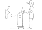
ひとたび収集袋30,130が満杯になるか、または空にする必要が生じると、可搬式の液体収集システム10を、例えば医療作業者170によって廃棄ステーションに運び、図25に示すように、集められた液体を収集袋30,130から排出すればよい。収集袋30,130からの排出は、この袋の廃棄のために不可欠なものではない(例えば、満たされた収集袋30,130は、その内部空間にまだ液体が存在する状態で廃棄してもよい)が、本発明の一態様は、収集袋30,130からの排出が、袋の廃棄によって生じる赤袋廃棄物の量を減少させることを可能にする。
Once the
いくつかの例示的な変形において、廃棄ステーションは、収集袋30,130の排出口38(図1に示される実施)、入口139,139’(図15〜図19に示される変形)、または排出口546(図20〜図22に示される実施形態)と自動(または手動)接続するように構成された流体コネクタを有するドッキングステーション180を備えてもよい。図15〜図19に示される変形については、システム10のドッキングステーション180への係合の前に、ホース接合部134を取り外してもよい。ドッキングステーション180は、収集システム10が適切に係合していること、および/または排出プロセスが行われていることを示すための適切なインジケータ185を含んでもよい。
In some exemplary variations, the disposal station may include a discharge port 38 (implementation shown in FIG. 1), an
図26aは、本発明の態様に係る、廃棄ステーション用のインターフェイスボードを示している。インターフェイスボードは、電源への接続を示すライト156と、廃棄ステーションが使用中であることを示す視覚表示157とを含んでもよい。インターフェイスボードは、また、排出サイクルの停止を可能にするスイッチ158を含んでもよい。ボタン158は、サイクルを完全に、または単に一時的に停止することができる。
FIG. 26a shows an interface board for a disposal station according to an aspect of the present invention. The interface board may include a light 156 that indicates connection to a power source and a
集められた液体を、収集袋30,130から排出するために、いくつかの例示的な実施形態において、ドッキングステーション180は、2005年8月25日に公開された「廃棄物流体の廃棄の方法および装置」を題名とする米国特許出願公開第2005/0183780号に述べられた種類のエダクターを利用してもよく、この開示の全てが、本明細書に参考文献として組み込まれる。代わりに、または追加で、廃棄ステーションは、手動で収集袋30,130に接続して、そこから集められた液体を排出することができる、可動コネクタ(図示せず)を含んでもよい。
In order to drain the collected liquid from the
図27〜図33は、液体収集および廃棄システムの別の例示的な実施形態を示している。図27に示すように、システムは、液体収集袋230と、収集袋230を受けるように構成された硬質容器215とを含む。収集袋230は、蓋231と、蓋231の内側表面に取り付けられ、その間にほぼ密閉された内部空間を形成する折りたたみ可能なライナ235と、を含んでもよい。収集袋230が、硬質容器215の上部に設置されると、蓋231は、容器215の開口部をほぼ密閉することができる。図27に示すように、収集袋230は、収集袋230の内部空間を、適切な吸引源(例えば図1に示す真空ポンプ44)に接続するための、吸引導管233を含んでもよい。吸引導管233は、収集袋230が容器215に設置されると、吸引導管233が自動的に吸引源に接続するように構成してもよいが、操作者によって手動で吸引導管215に接続されるように吸引源を構成してもよい。
27-33 illustrate another exemplary embodiment of a liquid collection and disposal system. As shown in FIG. 27, the system includes a
収集袋230は、吸引導管233の一端に配置された吸引遮断装置238を含んでもよい。より詳細に説明されるように、遮断装置238は、収集袋235内の液面が所定の高さに達した際に、吸引導管233を閉じて、集められた液体が吸引源に流れ込むことを防止してもよい。例示的な一実施形態において、遮断装置238は、液体の通過を防止するフィルタを備えてもよく、このフィルタは、例えば図24aに示される装置894’と同様のものであってもよい。フィルタは、収集袋230内に位置する吸引導管233の近端に配置してもよく、収集袋230内の液面がフィルタよりも上昇してフィルタを水没させた場合に、フィルタが吸引導管233を閉じ、吸引力の供給を遮断して液体収集プロセスを終了させてもよい。代わりに、または追加で、遮断装置238は、液体に触れると膨張して吸引導管233を密閉することができる親水性材料を含んでもよい。特定の実施においては、遮断装置は、蓋から延びるケージ内に配置された浮揚体(疏水性材料によりコーティングまたは覆われていてもよい)を備えてもよく、液面が許容可能な高さ位置よりも上昇した際に、浮揚体が吸引導管を閉じるようにしてもよい。
The
蓋231は、弾性のスリット弁などの軟質弁226によって通常は閉じられているアクセス口220を定義してもよい。後に詳述するように、アクセス口220は、ホース接合部240および排出コネクタ340を受けるように構成してもよい。ホース接合部240または排出コネクタ340が、アクセス口220に挿入されると、軟質弁226をたわませて、アクセス口220を開いてもよい。アクセス口220は、また、本明細書により詳しく述べるように、ホース接合部240および/または排出コネクタ340と関連する弁を開く作動ロッドまたはピン224を含んでもよい。
The
硬質容器215は、図4に示される容器80と同様に、長い管状の形状を有してもよい。硬質容器215は、上述の液体収集システム10のキャビティ15を構成してもよい。容器215は、容器215内に摺動可能に配置されたピストン280(注射器に類似する)を含んでもよい。ピストン280は、ピストン280の外周端に取り付けられたOリング283などの、1つまたは複数の密閉部材を含んでもよい。これにより、ピストン280は、容器215の内部空間を、上空間281と下空間289とに分けてもよい。ピストン280は、また、ピストンの移動中に、ライナ235が容器215の内壁とピストン280の間に挟まれることを防止する、ピストンスクレーパ285を含んでもよい。Oリング283とピストンスクレーパ285を、潤滑性および/または耐久性を高めるために、適切な材料(例えばパリレン)によってコーティングしてもよい。
The
ピストン280は、中間部分に、上空間281と下空間289との間の真空連通を可能にする貫通孔284を含んでもよい。貫通孔284は、よって、上空間281に真空力を供給し、この真空力は、液体収集段階の間に、収集袋230の内部空間内で加えられる真空力を相殺することができ、ライナ235がつぶれることを防止する。ピストン280は、貫通孔284内に位置する逆止弁286を含んでもよい。逆止弁286は、ばね288によって貫通孔284の開口部に対して付勢され、通常は貫通孔284を閉じている。いくつかの例示的な変形において、逆止弁286は、モジュール式の逆止弁差込み内に配置してもよく、この差込みを、貫通孔284に挿入してもよい。
The
容器215は、図29aに示すように、容器215の上部近くに、ピストンスクレーパ285と相互作用するストッパ290を含んでもよい。ストッパ290に加えて、容器は、収集袋の排出の間にピストンが上向きに移動する際に、収集袋がピストンスクレーパ285とストッパ290の間に挟まれることを防止する、挟み込み防止機構291をさらに含んでもよい。挟み込み防止機構の一変形は、容器215の内壁の間に位置する軟質カラー291を含んでもよい。例えば、容器が円筒形である場合、軟質カラーは、軟質の円筒形のカラーを含んでもよい。軟質カラー291は、図29bに示すように、溝292を含んでもよく、プラスチックまたはゴムなどの軟質材料を備えてもよい。ピストン280が容器内で上昇するにつれて、軟質カラー291は、容器の内部に向かって湾曲し、収集袋235を圧縮して容器の壁から押し離し、一方で図32aに示すようにその中の溝を閉じる。これは、収集袋が廃棄の間に折りたたまれるにつれ、ピストンスクレーパ285とストッパ290の間に袋が挟まれることを防止する。
The
図27に示すように、容器215は、下空間289を真空源または大気のいずれかに選択的に接続する、任意の三方弁265を含んでもよい。容器215は、例えば真空源に通気口がある場合、任意の三方弁なしに構成してもよい。例えば、三方弁265は、下空間289と連通する第1の接続262と、大気と連通する第2の接続264と、吸引源と連通する第3の接続268との3つの接続を有してもよい。三方弁265の動作特性は、図28〜32を参照してより詳細に述べられる。容器215は、また、図27に示すように、ピストン280が第1の接続262の高さよりも下がることを防止するストッパ270を、その底の近くに含んでもよい。あるいは、例えばポンプ(図示せず)がオフにされた際に、例えば逆の通気(大気へ)が自然に達成される場合は、弁265はなくてもよい。
As shown in FIG. 27, the
図27に示すように、ピストン280は、最初に、収集袋230を受けるために、容器215の上部近くに配置してもよい。収集袋230が、その折りたたまれた状態で、容器215内に据え付けられた後、図28に示すように、ホース接合部240をアクセス口220に挿入すればよい。ホース接合部240は、その流体通路245を開閉する通常閉の弁249(例えばダックビル弁、逆止弁、ばね押し弁、ポペット弁)を含むことを除いて、図15、図16、図18、および図19に示されるホース接合部134と同様である。弁249は、アクセス口220内に位置する作動ピン224によって、その通常閉位置から開かれるようにしてもよい。すなわち、アクセス口220に挿入されると、作動ピン224が弁249を押し、通路245を開く。ホース接合部240は、収集袋230が容器215に設置される前に、アクセス口220に挿入してもよい。
As shown in FIG. 27, the
ひとたび収集袋230が容器215に設置され、ホース接合部240が収集袋230のアクセス口220に確実に配置されると、任意の三方弁265を回転させて、第1の接続262を第3の接続268に合わせて、下空間289内の圧力と連通させればよい。下空間289に加えられる吸引圧は、ピストン280を容器215内に引き込み、これは一方で、図29に示すように、ライナ235をキャビティ内に引き込む。一変形において、ライナ235の内部空間は、大気に解放されており(または下空間289に加えられる吸引圧よりもいくらか大きな圧力下にあり)、ピストン280の下方への移動を促がす。下空間289に加えられる吸引力は、貫通孔284を開いて、上空間281内の過剰空気を排出させるために、逆止弁286の開弁圧よりも大きくてもよく、これは、蓋231と容器215の間のシールを強化することができる。しかし、逆止弁286は、ピストン280が下方に移動する間、閉位置のままにして、下空間289と上空間281の間の圧力差をさらに強くし、キャビティ内でのピストン280の下方移動をさらに促すようにすることが、好ましい場合もある。逆止弁286の感度は、下空間289に供給される吸引圧、上空間281に供給される任意の吸引圧およびライナ235の内部空間に供給される大気(または正)圧、を考慮して選択してもよい。逆止弁感度の選択では、本明細書でさらに述べるように、ピストン280の両側での効率的な圧力差および/またはバランスを利用して、その下方移動を促すことができる。
Once the
その後、図29に示すように、液体を収集袋230内に吸い込ませることができる。液体収集プロセスは、図12を参照して上述したプロセスとほぼ同様であり、よって、その詳細な説明はここでは省略する。上述したように、液体収集プロセスの間、下空間289内で連続して加えられた吸引力は、逆止弁286を開かせて、吸引圧を上空間281に連通させることができ、これは、液体収集プロセスの間に、収集袋230の内部空間内の吸引力を相殺して、ライナ235のつぶれや歪みを防止または減少することができる。
Thereafter, as shown in FIG. 29, the liquid can be sucked into the
液体収集プロセスは、その後、例えば医療処置の完了などにより終了してもよい。この動作は、また、吸引圧遮断の結果として終了してもよく、これは、例えば液面が遮断装置238の高さまで上昇した場合に起こり得る。例えば、図30に示すように、液面が遮断装置238の高さに達すると、遮断装置238は、自動的に導管233を遮断して液体収集プロセスを停止することができる。液体収集プロセスを継続する場合は、例えば、図13および図14を参照して上述したバックアップ保管容器20を用いて、プロセスを継続してもよい。
The liquid collection process may then be terminated, for example by completing a medical procedure. This operation may also end as a result of suction pressure blockage, which can occur, for example, when the liquid level rises to the height of the shut-off
収集袋230を空にするには、図31に示すように、収集袋230を保持する容器215を、廃棄ステーション300(例えばポンプアセンブリ)まで運べばよい。収集袋230を廃棄ステーション300に接続する前に、1つまたは複数の医療装置を保持しているホース接合部240を取り外し、例えば赤い袋に入れて廃棄してもよい。ホース接合部240の滴下防止弁249は、アクセス口220から取り外す際、流体通路245を閉じる(例えば、作動ピン224が、弁249を開いた状態に保持しなくなる)。また、ホース接合部240を取り外す際、軟質弁226は、その元の形状に戻って、アクセス口220を閉じてもよい。アクセス口220が閉じることは、集められた液体を、廃棄ステーションへの運搬のために収集袋230内に保持することができる。軟質弁226は、また、アクセス口220から取り外す間、ホース接合部240に対するワイピング機能を提供してもよい。このワイピング機能は、取り外しおよび廃棄の間にホース接合部240の滴下をなくすことを助けることができる。
In order to empty the
図31に示すように、廃棄ステーション300は、集められた液体を収集袋230から抜き取るのに十分な真空源を提供する、エダクター350を含んでもよい。図31に示されるエダクター350に加えて、他の真空または吸引源を用いて、収集袋230から廃棄ステーションへと流体を抜き取ってもよい。例えば、ロータリーポンプまたはピストンポンプなどのポンプ、あるいは他の適切な装置(例えば柔軟膜装置)を用いて、収集袋230の内容物を排出してもよい。収集袋230を廃棄ステーション300に接続するには、ホース接合部240をアクセス口220に挿入するのと同様のやり方で、廃棄コネクタ340を収集袋230のアクセス口220に挿入すればよい。ホース接合部240と同様に、廃棄コネクタ340は、廃棄コネクタ340の遠端を閉じるように付勢された滴下防止コネクタ弁345を含んでもよい。廃棄コネクタ340の挿入は、コネクタ弁345を開かせて、アクセス口220とエダクター350との間の流体連通を確立させることができる。
As shown in FIG. 31, the
エダクター350は、液体を収集袋230から抜き取るために十分なポンプ力を生成するために、水または他のすすぎ流体源305と、下水道390との間に配置してもよい。すすぎ流体は、水、他の洗浄流体(例えば洗剤または他の流体)、または水と他の洗浄流体の混合からなっていてもよい。上述したように、用語「流体」は、個体粒子を含む液体媒体と、気体および/または微粒子の組み合わせを指すことができる。図31に示すように、エダクター350は、水導管315および排出管380のそれぞれを介して、水源305および下水道390に接続してもよい。水導管315は、手動または電気スイッチなどの他の制御によって制御可能な水弁310を含んでもよい。加えて、ベンチュリ360を適切に(例えば排出管380のエダクター350の近くに)配置して、より大きなポンプ力を生成するようにしてもよい。廃棄コネクタ340を、次いで、排出管335を介してエダクター350に接続してもよい。
The
動作中に、図32に示すように、水弁310を開くことで、水源305からの水が、エダクター350に流れ込み、エダクター350内にポンプ力を生成する。このポンプ力は、ライナ235を折りたたませ、次いで、収集袋230内に集められた液体を、エダクター350へ、そして排出管380を介して下水道390へと流れ込ませる。ライナ235の折りたたみ形状寸法を、所望の排出液体の流れをふさいで妨げないようなやり方で制御するために、逆止弁286を閉位置にセットしてもよい。逆止弁286の閉位置は、ライナ235と容器215の間の空間に空気が流れ込むことを防ぐ。ライナ235の外側の空間に、比較的制限された空気があるため、ライナ235の壁面は、容器215の壁面から遠ざけられず、よって、ライナ235内の液体の流れを遮断しない。この段階で、任意の三方弁265は、下空間289を、図32に示すように、第1および第2の接続262,264を介して大気と連通するように調整してもよい。この選択は、下空間289内の圧力を、排出プロセスの間に大気圧に到達させ、ライナ235の折りたたみと干渉しないようにする。例えば、下空間289の圧力を大気圧に維持することは、上空間281(吸引圧を受ける)と下空間289(大気に解放している)の間の圧力差により、排出プロセスの間にピストン280を上昇させる。ライナ235が折りたたまれるつれてピストン280が上昇するので、ライナ235の折りたたみは、主にピストン280の近くで行われ、排出プロセスの間にライナ235の側壁をふさぐことを効果的に防止できる。
During operation, as shown in FIG. 32, by opening the
廃棄ステーション300は、水導管315から分岐して廃棄コネクタ340に浄水を供給するする導管325を含んでもよい。導管325は、廃棄コネクタ340の内部に流れ込む水を制御する弁320(例えば電磁弁またはボール弁)を含んでもよい。液体が収集袋230から取り出された後、水源305からの浄水を、廃棄コネクタ340の内部に流し込ませてもよく、これは、すすぎまたは洗い流す目的、および廃棄コネクタ340の予防メンテナンスとして、1または複数回オンとオフを繰り返すことができる。この動作は、排出コネクタ340をアクセス口220から取り外す前に行われてもよく、これにより例えば、洗浄水が排出コネクタ340の外部に流れ、次いで、エダクターの吸引により排出コネクタの内部を通して吸い戻されることを可能にする。
The
よって、廃棄コネクタ340は、清浄なすすぎ流体を供給する1つのチャンネルと、汚染された流体を排出する第2のチャンネルとの、2つのチャンネルと連通可能である。第2のチャンネルは、例えば、図32に示すように、また同様に図51を参照して示され述べられるように、第1のチャンネル内に位置してもよい。ボール弁などの弁が、チャンネルのうちの1つ内に配置される。液体収集容器の内容物が排出された後、すすぎ流体が、第1のチャンネルから、弁の中とその周りを流れ、弁の表面全体を洗い流す。弁がボール弁である場合、すすぎ流体は、弁ハウジングの周りの円筒形の通路を流れ、これにより、弁が完全にすすぎ流体ですすがれる。弁を介して、すすぎ流体は、液体収集容器の内容物と同様に、第2のチャンネルに入って排出される。よって、第2のチャンネルは、すすぎ流体によっても洗い流される。この手法は、廃棄コネクタが、それ自体および液体収集容器との接続の両方を、自動的に洗浄することを可能にする。とりわけ、この自動すすぎ機能は、ユーザが医療処置で集められた液体と接触することを防止する。
Thus, the
本発明の一態様によると、導管325(廃棄コネクタ340に洗浄水を供給する)は、排出管380と流体連通しており、これを用いて、エダクター350を「充填」し、これにより、収集袋30から(上述したように)流体を吸引する。このようにして、洗浄流体は、エダクターが収集袋30から流体を吸引していない限りは、廃棄接続340に供給されず、意図せず収集袋30に洗浄水を溢れさせることを防止する。
In accordance with one aspect of the present invention, conduit 325 (which supplies wash water to waste connector 340) is in fluid communication with
ひとたび許容量の液体が収集袋230から取り出され、収集袋230が折りたたまれると、排出コネクタ340がアクセス口220から取り外される。軟質弁226が、次いでアクセス口220を閉じ、収集袋230を密閉し、かつ袋230を折りたたみ状態に維持する。そして、収集袋230は容器215から取り外され、例えば赤い袋に入れられて廃棄される。新しい収集袋230’を、次の一連の医療処置に向けて、図33に示すように、容器215に設置してもよい。
Once an acceptable amount of liquid is removed from the
図34は、収集袋415のアクセス口420に関連するインターフェイス440(または排出コネクタ340)の例示的な一変形を示している。インターフェイス440は、流体通路445を定義し、例えば通路445の遠端に位置するポペット弁449を有してもよい。アクセス口420は、通常閉の軟質スリット弁426と、作動ピン424とを含む。図34に示される例示的なスリット弁426は、軟質で滴下防止の逆止弁である。この弁は、プラスチック等の軟質材料、ゴムまたは他の適切な材料でつくられていてもよい。加えて、インターフェイス440用の開口部の役割を果たすために、弁426は通常閉の二方逆止弁として機能する。この弁は背圧に耐え、液体収集袋内の真空圧の維持を助ける。この手法は、先に使用された空にされた袋を、ほぼ折りたたんだ状態に維持することを助ける。この手法は、さらに、収集袋内の廃棄物が袋から滴ったり出たりすることを防止することにより、安全機能を提供する。よって、排出された収集袋は、ひっくり返したり絞られたりしても、廃棄物を漏出することがない。インターフェイス440がアクセス口420と係合すると、作動ピン424は、ポペット弁449と係合し、インターフェイス440の流体通路445を開く。また、インターフェイス440の遠端は、インターフェイス440がアクセス口420と係合すると、スリット弁426を係合可能に開く。
FIG. 34 illustrates an exemplary variation of the interface 440 (or drain connector 340) associated with the
図35〜図38は、本発明の態様に係るピストン580の他の例示的な実施形態を示している。図37に示すように、ピストン580は、概ね凸状の上面581を有する本体585を含んでもよい。本体585は、ピストン580の上下の空間の連通を可能にする貫通孔580を、その中心に定義する。本体585の上面の下側に、本体585は、逆止弁アセンブリ570を受ける凹部582を形成してもよい。逆止弁アセンブリ570は、支持構造577に包まれた逆止弁575を含んでもよい。支持構造577は、本体585に対し、図38に示すように、例えばネジ573、あるいは他の取付または貼付機構を介して固定してもよい。
35-38 illustrate another exemplary embodiment of a
特定の状況下では、装置に含まれる液体収集袋のライナは、貫通孔586をふさいで、ピストン580上のキャビティ内の空間に対する吸引の供給を妨げることがある。このような妨げを防止または減少するために、複数の通気孔595を有する上げ底592を、本体585の上面581に形成または配置してもよい。上げ底592は、例えば1つまたは複数のネジによって上面581に固定してもよい。この目的のために、図36および図37に示すように、上げ底592は、複数のネジ穴593を含んでもよく、本体585は、上げ底592のネジ穴593と揃えられた複数の対応するネジ穴589を含む。上げ底592は、また、図38に示すように、その底面からほぼ垂直に延び、本体585の上面581からの所望の間隔を維持する複数のスペーサリブ594を含んでもよい。複数のネジ穴593を定義する上げ底592の構造は、上げ底592の底面から下向きに延びて、追加のスペーサとして機能させてもよい。ひとたび、上げ底592が、本体585の上面581に固定または形成されると、複数の通気孔595は、本体585の貫通孔586と連通する。複数の通気孔595に対して均一に真空力を供給するために、本体585の上面581は、貫通孔586から横方向に延びる複数の溝587を定義してもよい。
Under certain circumstances, the liquid collection bag liner included in the device may block the through-
ピストン580は、また、本体585の外周端に取り付けられたOリング588等の1つまたは複数の密閉部材を含んでもよい。本体585は、密閉部材を受けるための1つまたは複数の円周溝を形成してもよい。ピストン580は、また、液体収集袋のライナがキャビティの内壁とピストン580の間に挟まれることを防止するように構成された、スクレーパリング583を含んでもよい。図27〜図33を参照して上述したように、Oリング588およびスクレーパリング580は、潤滑性および/または耐久性を強化するために、適切な材料(例えばパリレン)によってコーティングしてもよい。いくつかの例示的な変形において、スクレーパリング583は、図38に示すように、本体585の周辺端にピン留めあるいは取り付けまたは接着してもよい。ピストンおよびスクレーパリングは、また、1つの連続体を備えてもよい。代わりの実施形態において、Oリング588および/またはスクレーパリング583は、組み立てを容易にするために、例えば二個取成形プロセスによって、本体585内に成形してもよい。ピストン580の動作特性は、図27〜図33を参照して上述したピストン280の動作特性と同様であり、よって、そのさらに詳細な説明は、ここでは省略する。
The
図39〜図41は、本発明の態様と一致するピストン680の他の例示的な実施を示している。ピストン680は、貫通孔686と、弁アセンブリ675を受けるための中央凹部と、を有する本体685を含む。弁アセンブリ676の、貫通孔686および中央凹部に関連する配置は、図35〜図38に示される変形の配置とほぼ同様であり、よって、そのさらに詳細な説明は、ここでは省略する。
39-41 illustrate another exemplary implementation of a
図39に示すように、本体685は、概ね凸形状を有する上面凹部681を含んでもよい。上面凹部681は、偽底692を構成する材料のシートを受けるように構成してもよく、この偽底は、液体収集袋のライナを構造的に支持し、ライナを上面凹部681の表面から所望の間隔で維持してもよい。上げ底592と同様に、偽底692は、ライナが、ピストン680上のキャビティ内の空間に対する真空の供給を妨げることを、防止することができる。いくつかの例示的な実施においては、偽底692は、1つまたは複数のネジ693あるいは他の取り付けまたは貼り付け機能によって上面凹部681に固定してもよい。ネジ使用の目的のために、本体685は、複数のネジ穴684を定義してもよい。
As shown in FIG. 39, the
図40に示される変形において、偽底692は、ピストン680の本体685にネジ留めされたプラスチックまたは他の適切な材料メッシュによって形成してもよい。メッシュは、複数の突起695を含んでもよく、これら突起は、液体収集袋のライナを集合的に支持してもよい。代わりの変形において、偽底692は、メッシュに編み込まれたモノフィラメント繊維(例えばナイロン、ポリエステル、ポリプロピレン、PEEK、PTFE)で形成してもよい。さらに他の代わりの変形において、偽底692は、様々な多孔パターン(例えば直線またはジグザグの孔パターン)を有する多孔シートで形成してもよい。単に例示として、多孔シートは、ポリプロピレンまたは高強度PVC製であってもよい。
In the variation shown in FIG. 40, the
例示的な一実施において、本体685は、貫通孔686を区切る構造から放射状に延びる複数のリブを有して形成してもよい。本体685は、底凹部687を形成してもよい。とりわけ、複数のリブおよび底凹部687による、本体685の形成は、本体685の材料の量を減少(よって製造コストを低減)させるだけでなく、ピストン680の総重量を減少することもでき、ピストン680の動作性を高めることができる。
In one exemplary implementation, the
図42は、液体収集システム10と関連する様々な構成要素およびそれらの動作特性を示す、液体廃棄ステーション900の概略図を示している。液体収集袋が満杯になるか、または空にする必要が生じると、可搬性の液体収集システム10は、図25を参照して上述したのと同様に、廃棄ステーション900まで運ばれる。廃棄ステーション900は、基準構造987(図44および図45も参照)と、液体収集システム10の対応するラッチ部材990(図46および図47も参照)を係合するために基準構造987に固定されたラッチ部材980と、を含んでもよい。この手法は、特に、液体収集システム10を確実かつ正確に、廃棄ステーション900に対する所定位置に配置することを可能にする。図45に最良に示すように、廃棄ステーション900のラッチ部材980は、内部空間982を定義して、液体収集システム10のラッチ部材990を離脱可能にロックするための機械式ロック986(図46を参照)を受けるように、サイズ決めおよび構成してもよい。機械式ロック986は、開口部983(図45)を通って突出する部分を含んでもよい。開口部983を通って突出する部分は、保持部材987によって保持してもよい。内部空間を定義する構造は、環状空間981によって囲まれていてもよい。ラッチ部材980は、また、液体収集システム10のラッチ部材990との係合を容易にするためのガイド構造を含んでもよい。ガイド構造は、液体収集システム10に面する方向に延び、概ねテーパ状の内面985と、概ねテーパ状の外面984と、を有していてもよい。
FIG. 42 shows a schematic diagram of a
液体収集システム10のラッチ部材990は、廃棄ステーション900のラッチ部材980のガイド構造を受けるように構成された主引込構造992を含んでもよい。引込構造992は、ガイド構造の形状に概ね一致した形状を有してもよい。上述したように、ガイド構造の概ねテーパ状の内面および外面984,985は、主引込構造992とガイド構造の位置合わせを容易にすることができる。引込構造992は、また、ガイド構造との位置合わせを容易にするための傾斜面991を有してもよい。図46および図47に示すように、ガイド構造のテーパ状の内面および外面984,985および/または引込構造992の傾斜面991は、初期位置合わせ不良のより大きな許容度を可能にすることができる。
The
ラッチ部材990は、また、ラッチ部材990のベースから延びるシュラウド996を含んでもよい。横断壁999が、シュラウド996を横切って延びていてもよく、ラッチポスト998を、横断壁999に取り付けてもよい。ひとたび、主引込構造992が廃棄ステーション900のガイド構造と位置合わせされると、液体収集システム10を廃棄ステーション900に向けてさらに動かすことによって、シュラウド996が、ラッチ部材980の環状空間981と係合する。環状空間981との係合によって、シュラウド996は、液体収集システム10をガイドして、廃棄ステーション900と正確に位置合わせすることができる。シュラウド996が環状空間981に完全に挿入されると、ラッチポスト998は、液体収集システム10を廃棄ステーション900に確実に固定するように、開口983を介して機械式ロック986と係合してもよい。図42aおよび図42bは、廃棄ステーション900の各セクションの例示的な実施を示している。図42cは、廃棄ステーション900の例示的な機能および動作を示している。
The
図43は、廃棄ステーション900と完全に係合した液体収集システム10を示している。図43aおよび図43bは、廃棄システムから分離された、液体収集システムの例示的な実施を示している。特定の例示的な変形において、液体収集システム10から液体を排出させるためのプロセスを、ラッチスタッド998と機械ロック986とが係合した際に自動的に開始させてもよいが、システムは、システム10が廃棄ステーション900と動作的に係合された後に、操作者が手動で排出プロセスを開始する必要があるように構成してもよい。
FIG. 43 shows the
廃棄ステーション900は、例えば基準構造987に固定され、廃棄ステーション900の近傍で液体収集システム10の存在を検出するように構成されているセンサユニット995を含んでもよい。廃棄ステーション900は、液体排出プロセスの開始前に、廃棄ステーション900における液体収集システム10の存在が、センサユニット995によって確認されるように構成してもよい。よって、センサユニット995を、廃棄ステーション900内の液体排出プロセスの誤った開始に対する安全策として使用することができる。
The
液体収集システム10が廃棄ステーションに確実に設置されると、排出インターフェイス960および介在インターフェイス970が、液体収集システム10の排出口540’および介在口516’と、図48に示すように、それぞれ揃うことができる。介在インターフェイスの使用は任意である。廃棄ステーションは、また、どのような介在接続または介在吸引もなしに機能するように構成してもよい。例示的な実施において、介在インターフェイス970は、固定サポート965を介して、排出インターフェイス960に接続されてもよい。排出インターフェイス960および介在インターフェイス970は、液体収集システムから液体を排出するための適切な排水システムに接続してもよい。いくつかの例示的な変形において、廃棄ステーションのためのドレンシステムは、図42に示すように、液体収集システム10の収集袋から、集められた液体を抜き取るのに十分な吸引圧源を提供するエダクター350を含んでもよい。集められた液体を排出するための、エダクター350および関連するフロー接続は、例えば、図31および図32を参照して上述したものと同様に動作してもよい。
When the
廃棄ステーションにおける、エダクター350と液体収集袋30の間のフロー接続は、この変形が、介在インターフェイス970に吸引力を供給するための、排出導管335から分岐する側部導管938を含む点が、図31および図32に示したものと異なっていてもよい。介在インターフェイス970は、図48および図52に示すように、液体収集袋30の蓋530’に形成された介在口516’と接続するように構成してもよい。上述したように、介在インターフェイスは任意であり、廃棄システムは、介在真空からのどうような真空圧もなしに機能するように構成してもよい。例えば、介在ホース接合部970が、介在口516’に挿入されると、介在インターフェイス970の通路917が、図52に示すように、介在空間と連通してもよい。適切な密閉部材918(例えばOリング)を設けて、介在口516’の内面と介在インターフェイス970の外面の間のギャップを密閉してもよい。図20〜図22を参照して上述したように、蓋530’の介在口516’は、液体収集袋の外部のキャビティ内の介在空間と流体連通していてもよく、また、介在空間への吸引力の供給が、排出プロセスの間に、収集袋の内側と外側の圧力を等しくさせてもよく、これにより、排出プロセスの間に、収集袋をほぼ折りたたまれていない状態に留めさせてもよい。蓋530’に、介在口516’を設けることは、排出プロセスの間の液体収集システム10内の電源の必要性をなくすことができ、そうでない場合、図12の第2の真空コネクタ64の機能と同様に、介在空間に吸引源を供給する必要性を生じ得る。他の変形において、液体収集袋の蓋とキャビティ15の上部11の間のシール、および少なくともピストンとキャビティの内壁の間のシールが、介在空間への空気の侵入を防ぐことによって、収集袋の外側の真空圧を維持し、排出プロセスの間に袋の側面が折りたたまれないようにする。袋とキャビティの内壁の間の介在空間への通気を制限することにより、吸引源と介在空間の間の連通は、排出プロセスの間、必要/任意となる。加えて、介在空間への通気は、ピストン内の逆止弁575によって制御してもよい。これらのシールは、収集プロセスの間に、収集袋の内側と外側の圧力の等化を補助し、排出プロセスの少なくとも一部を通して、その圧力を維持し続ける。
The flow connection between the eductor 350 and the
例示的な変形において、排出プロセスの終わり近くで介在空間への通気を可能にし、大気と介在空間を連通させることにより、液体収集袋30を完全に折りたたむようにしてもよい。例えば、排出サイクルの最後の約30秒間等、廃棄サイクル内の所定の時間に、空気を介在空間に流れさせてもよい。例示的な実施においては、介在空間は、介在口516’および大気との連通を確立させることによって、アクセスされてもよい。例えば、廃棄ステーションは、介在口516’内の破断可能部分を貫通して、排出プロセスの終わり近くで介在空間に空気を流れ込ませてもよい。ドッキングステーションは、排出プロセスの時間を計り、排出サイクルの終了前の所定時間において介在空間との連通を確立する、タイマを含んでもよい。
In an exemplary variation, the
他の変形において、ソレノイド弁または電子弁等の弁を用いて、排出プロセスの終わり近くで、介在空間に通気を提供してもよい。しかし、ドッキングステーションを使用して、介在区間との大気連通を確立することは、廃棄サイクルが、電動でない液体収集容器および可搬式のユニットにおいて動作することを可能にする。 In other variations, valves such as solenoid valves or electronic valves may be used to provide ventilation to the interstitial space near the end of the evacuation process. However, using the docking station to establish atmospheric communication with the intervening section allows the waste cycle to operate in non-powered liquid collection containers and portable units.
一定の例示的な実施形態によると、廃棄ステーションは、直線スライド952を含んでもよく、これに沿って、排出インターフェイス960および介在ホース接合部970を、それぞれ排出口540’および介在口516’と摺動可能に係合してもよい。排出インターフェイス960と介在インターフェイス970の、直線スライド952に対する移動は、例えば、コンプレッサー958または他の適切な移動機構と、フロー制御パイロット956と、フロー制御弁954(例えば二方ソレノイド弁)とにより、図42に示し説明したのと同様に、空気圧で制御してもよい。フロー制御弁954は、電力が失われた場合に、圧力を維持するように構成してもよい。あるいは、接合部960および接合部970を、自動または手動のいずれかで、任意の他の直線作動装置によって制御してもよい。
According to certain exemplary embodiments, the disposal station may include a
図48および図48aに最良に示すように、排出口540’と介在口516’は、液体収集プロセスの間、破断可能なクロージャ部材544’,514’によって閉じたままにしてもよい。これらの破断可能なクロージャ部材544’,514’は、排出インターフェイス960および介在インターフェイス970が、排出口540’および介在口516’と係合した際に、貫通または切断してもよい。このような貫通を容易にするために、排出インターフェイス960および介在インターフェイス970は、それぞれ、鋭利な遠端966,915を含んでもよい。
As best shown in FIGS. 48 and 48a, the outlet 540 'and the interstitial 516' may remain closed by breakable closure members 544 ', 514' during the liquid collection process. These breakable closure members 544 ', 514' may penetrate or cut when the
図49および図50に示すように、排出インターフェイス960は、その通路を開閉する通常閉の弁962,963(例えばダックビル弁、逆止弁、ばね押し弁、ポペット弁)を含んでもよい。図49、図49a、図49b、および図50に示す例示的な変形において、弁は、ばね962によってホース接合部960の遠端向けに付勢されたボール963を含む。弁962,963は、その通常閉の位置から、例えば排出口540’の内部に配置された作動ロッドまたはピン541’によって開いてもよい。
As shown in FIGS. 49 and 50, the
よって、弁962,963が、排出口540’に挿入されると、作動ピン541’が、弁962,963と係合して、図50に示すように、排出ホース接合部960の通路を開く。排出口540’は、図51に示すように、通常閉の軟質弁542を含んでもよい。弁542は、図34を参照して上述したスリット弁426と同様であってもよく、よって、そのさらに詳細な説明は、ここでは省略する。排出インターフェイス960が、排出口540’に挿入されると、例えば、弁542がたわんで排出口540’を開いてもよい。
Thus, when the
図51は、排出口540’と係合した状態の排出インターフェイス960の断面図であり、インターフェイス960を洗浄するための洗浄水の例示的な流れを示している。図42に示すように、廃棄ステーション900は、水導管315から分岐して、排出ホース接合部760に洗浄水または他の洗浄物質を供給する導管325を含んでもよい。収集袋から液体が取り出された後、導管325からの浄水または他の物質を、洗浄チャンバ974を通して排出ホース接合部760の内部に流れ込ませてもよく、これは、1または複数回オンとオフを繰り返して、排出インターフェイス760の予防メンテナンスとしてすすぎまたは洗い流しを行うことができる。洗浄作業は、排出インターフェイス760を排出口540’から取り外す前に行ってもよく、これにより、洗浄物質を、排出インターフェイス760の外部に流れさせ、次いで排出インターフェイス760の内部に吸い戻させることができ、インターフェイス760の内部の構成要素から、残留する流体または他の粒子を洗い流す。
FIG. 51 is a cross-sectional view of the
廃棄ステーション900は、廃棄ステーション900の状態を示し、かつ/または廃棄ステーション900の様々な機能の制御を可能にするためのインターフェイスボード993を含んでもよい。例えば、図42に示すように、インターフェイスボード993は、液体排出プロセスを停止するための停止ボタンを含んでもよい。インターフェイスボード993は、また、その動作特性、および/または例えばステーションが使用中かどうか等の状態に関する様々な情報を提供する、1つまたは複数の視覚または音響インジケータを含んでもよい。
The
本発明の態様の例示的な実施は、可搬式のユニットと、使い捨て流体収集容器とを含む流体収集システムを含んでもよい。可搬式のユニットは、例えば図2aに示すようなユーザインターフェイスと、例えば図4に示すようなキャビティとを含んでもよく、このキャビティは、使い捨て流体収集容器を受けるように構成されている。キャビティの上部は、図4に示される軟質フランジ81等の、境界コネクタを含んでもよい。可搬式のユニットは、真空ポンプと、HEPAフィルタ/トラップと、ピストンと、ピストン逆止弁とを、図11a〜cに示されるもの等の他の機能とともに含んでもよい。
Exemplary implementations of aspects of the present invention may include a fluid collection system that includes a portable unit and a disposable fluid collection container. The portable unit may include, for example, a user interface as shown in FIG. 2a and a cavity as shown in FIG. 4, for example, which is configured to receive a disposable fluid collection container. The top of the cavity may include a boundary connector, such as the
ピストンは、図22aのピストン280に関して示すように、可搬式のユニット内のキャビティに配置してもよい。ピストンは、さらに、キャビティの内壁に当接するスクレーパリングと、ピストンおよびキャビティの内部の側面の間に挟まれた少なくとも1つのOリングと、図35〜図38に示すような逆止弁等の逆止弁アセンブリとを含んでもよい。
The piston may be placed in a cavity in the portable unit, as shown with respect to
可搬式のユニットは、また、バックアップ容器に吸引を供給するために、可搬式のユニットの側部に真空口を含む、バックアップ容器を取り付けるための取付片を含んでもよい。 The portable unit may also include a mounting piece for mounting the backup container, including a vacuum port on the side of the portable unit, for supplying suction to the backup container.
流体収集容器は、図10の要素35と同様の折りたたみ可能なライナと、図53〜図55に示される蓋等の蓋とを含んでもよい。図示するように、蓋は、排出源との連通を提供するように構成された開口部546を含んでもよい。開口部は、破断可能な部材と、二方逆止弁と、ピンとを含んでもよい。蓋は、また、例えば大気圧を、キャビティとライナの間の介在空間に連通させるための介在開口部を含んでもよく、この介在開口部は、破断可能な部材によって閉じられている。蓋は、また、流体を流体収集容器に吸い込ませる吸引器具とそれぞれ連通するように構成された、複数の口を含んでもよい。各口は、係留されたキャップを含んでもよい。蓋は、複数の口の内部開口部と、真空源と連通する開口部との間に位置し、集められた流体を真空源からそらすシェルフを含んでもよい。蓋は、また、開口部から排出開口部までを囲む仕切りを含んでもよい。蓋は、また、図53〜図55に示される追加の機能を含んでもよい。
The fluid collection container may include a collapsible liner similar to
ライナは、ホットメルトにより蓋に取り付けてもよい。使用前にライナは、また、ライナを蓋に対して折りたたんだ位置に保持する、破断可能なバンドを含んでもよい。 The liner may be attached to the lid by hot melt. Prior to use, the liner may also include a breakable band that holds the liner in a folded position relative to the lid.
この変形の流体収集システムを使用するために、ユーザは、使い捨て流体収集容器を、可搬式のユニットのキャビティの上部に設置する。蓋が可搬式のユニットに取り付けられると、折りたたみ可能なライナの内部と蓋により形成された空間と、真空源との間で、真空インターフェイスを介して連通が確立される。PPV式の弁等の弁を、蓋の一部に含ませて、液体が真空インターフェイスに入ることを防いでもよい。 To use this variant of the fluid collection system, the user installs a disposable fluid collection container on top of the cavity of the portable unit. When the lid is attached to the portable unit, communication is established through the vacuum interface between the interior of the foldable liner, the space formed by the lid, and the vacuum source. A valve, such as a PPV valve, may be included in part of the lid to prevent liquid from entering the vacuum interface.
真空源がオンにされると、真空源は、折りたたみ可能なライナの外部とキャビティの内部との間の介在空間に連通する。この真空圧は、流体収集容器のバンドを破断し、ピストンを第1の位置に引き下げ、例えば図28および図29に示すように、折りたたみ可能なライナをキャビティ内に膨らませる。真空圧は、キャビティの上部と蓋の間に位置するシール、ピストンとキャビティの間に挟まれた少なくとも1つのOリング、およびピストンの中央のピストン逆止弁のうちの少なくとも1つによって、介在空間において維持される。 When the vacuum source is turned on, the vacuum source communicates with the intervening space between the exterior of the collapsible liner and the interior of the cavity. This vacuum pressure breaks the band of the fluid collection container and pulls the piston down to the first position, causing the collapsible liner to expand into the cavity, as shown, for example, in FIGS. The vacuum pressure is caused by at least one of a seal located between the top of the cavity and the lid, at least one O-ring sandwiched between the piston and the cavity, and a piston check valve in the center of the piston to provide an intervening space. Maintained.
集められるべき流体は、蓋の少なくとも1つの口を通して、膨らんだライナ内に、真空源を用いて吸い込まれる。流体は、例えば図29および図30に示すようにライナを満たす。PPV弁は、流体が真空源に入るのを防ぐ。 The fluid to be collected is drawn through the at least one mouth of the lid and into the inflated liner using a vacuum source. The fluid fills the liner, for example as shown in FIGS. The PPV valve prevents fluid from entering the vacuum source.
処置の終了時または液体収集容器の使用が(例えば満杯になり)中断された場合に、可搬式のユニットは、例えば図43に示すように、廃棄ステーションまで運んでドッキングさせることができる。可搬式のユニットは、例えば図44〜図47に示すように、廃棄サイクル中に可搬式のユニットを廃棄ステーションに固定するように構成された取付機構を含んでもよい。廃棄ステーションは、可搬式のユニットの係合を検知して、自動廃棄サイクルを開始してもよい。廃棄ステーションは、また、例えば図26aに示すようなユーザインターフェイスと、図42a〜bに示されるような水道および廃棄物保管所への接続を含んでもよい。廃棄サイクルは、図23、図42および図42cと関連して述べたように進行してもよい。 At the end of the procedure or when use of the liquid collection container is interrupted (eg, full), the portable unit can be brought to a disposal station and docked, for example as shown in FIG. The portable unit may include an attachment mechanism configured to secure the portable unit to the disposal station during the disposal cycle, for example as shown in FIGS. The disposal station may detect the engagement of the portable unit and initiate an automatic disposal cycle. The disposal station may also include, for example, a user interface as shown in FIG. 26a and connections to water and waste bins as shown in FIGS. The discard cycle may proceed as described in connection with FIGS. 23, 42 and 42c.
廃棄ステーションは、図51に示すように、流体収集装置の蓋と連通するように構成された排出インターフェイスを含んでもよい。排出インターフェイスは、蓋の破断可能な部材を貫通し、蓋の二方逆止弁を押し開く。排出インターフェイスの開口部に向けて付勢されたボールが、蓋内のピンによって開口部から押し離され、排出インターフェイスが開かれる。 The disposal station may include a drain interface configured to communicate with the lid of the fluid collection device, as shown in FIG. The discharge interface passes through the breakable member of the lid and pushes the lid two-way check valve open. The ball urged toward the opening of the discharge interface is pushed away from the opening by the pin in the lid, and the discharge interface is opened.
例えばエダクターを用いて、吸引が加えられ、流体収集容器の内容物を、排出インターフェイスを介して排出する。内容物が排出されるにつれて、ピストンが、例えば図31〜図32に示すように、第2の位置に移動(例えば上昇)し、ライナが折りたたまれる。例えば図29a〜図32aに示されるような移動機構を、キャビティの内部に設けて、ライナがストッパとピストンの間に挟まれるのを防いでもよい。廃棄サイクルの終わり近くで、大気をキャビティとライナの間の介在空間に連通する蓋の開口部を閉じている破断可能な部材に穴を開けて、介在空間と大気圧との間で圧力調整を行わせ、かつライナを完全に空にするようにしてもよい。 For example, using an eductor, suction is applied and the contents of the fluid collection container are discharged through the discharge interface. As the contents are discharged, the piston moves (for example, rises) to the second position, for example, as shown in FIGS. 31 to 32, and the liner is folded. For example, a moving mechanism as shown in FIGS. 29a to 32a may be provided inside the cavity to prevent the liner from being pinched between the stopper and the piston. Near the end of the disposal cycle, adjust the pressure between the intervening space and atmospheric pressure by drilling a breakable member that closes the lid opening that communicates the atmosphere to the intervening space between the cavity and the liner. And the liner may be completely emptied.
廃棄ステーションは、きれいなすすぎ流体を供給する1つのチャンネルと、汚染された流体を排出する第2のチャンネルとの、2つのチャンネルを含むように構成してもよい。第2のチャンネルは、例えば、図32に示すように、また同様に図51に示し説明すように、第1のチャンネル内に配置してもよい。ボール弁等の弁を、チャンネルのうちの1つの内部に配置してもよい。集められた液体収集容器の内容物が排出された後、すすぎ流体が第1のチャンネルから弁の周りを流れ、弁の表面全体を洗い流す。弁がボール弁である場合、すすぎ流体は、弁ハウジングの周りの円筒形の通路を流れ、これにより、弁が完全にすすぎ流体によってすすがれる。弁を介して、すすぎ流体が第2のチャンネルに入り、液体収集容器の内容物と同様に排出される。よって、第2のチャンネルも、すすぎ流体によって洗い流される。この手法は、廃棄コネクタが、それ自体および液体収集容器との接続の両方を、自動的に洗浄することを可能にする。 The disposal station may be configured to include two channels: one channel that supplies a clean rinse fluid and a second channel that discharges contaminated fluid. The second channel may be located in the first channel, for example, as shown in FIG. 32 and as shown and described in FIG. A valve, such as a ball valve, may be placed within one of the channels. After the collected liquid collection container contents have been drained, rinse fluid flows from the first channel around the valve and flushes the entire surface of the valve. If the valve is a ball valve, the rinsing fluid flows through a cylindrical passage around the valve housing, thereby rinsing the valve completely with the rinsing fluid. Through the valve, the rinsing fluid enters the second channel and is drained in the same manner as the contents of the liquid collection container. Thus, the second channel is also washed away by the rinse fluid. This approach allows the waste connector to automatically clean both itself and the connection with the liquid collection container.
この時点で、可搬式のユニットを、廃棄ステーションから切り離すことができ、使い捨て流体収集容器を、取り外しおよび廃棄することができ、新たな使い捨て流体収集容器を挿入して、流体収集システムを他の処置のために用意することができる。 At this point, the portable unit can be disconnected from the disposal station, the disposable fluid collection container can be removed and discarded, a new disposable fluid collection container can be inserted, and the fluid collection system can be used for other procedures. Can be prepared for.
以上、本発明の態様を、その1つまたは複数の好適な変形を参照して説明および例示したが、これらの態様を、そのような詳細説明に限定することは、本出願者の意図ではない。むしろ、本出願者は、本発明の範囲に含まれる変形の、本明細書に提示されたものおよび当業者に既知のもの双方の全ての均等物によって、本発明の態様を定義することを意図している。 While embodiments of the present invention have been described and illustrated with reference to one or more suitable variations thereof, it is not the intention of the applicant to limit these embodiments to such detailed descriptions. . Rather, the Applicant intends to define embodiments of this invention by all equivalents of both those presented herein and those known to those of ordinary skill in the art that are within the scope of this invention. doing.
Claims (14)
上部開口を有するキャビティを有するハウジングと、
前記キャビティに受けられるように構成された流体収集容器と、を備え、
前記流体収集容器は、
前記上部開口を閉じるように構成された蓋と、
前記蓋が前記上部開口を閉じた際に、前記蓋と前記キャビティの間に配置されるようにして前記蓋に取り付けられた軟質ライナと、を備え、
前記軟質ライナと前記蓋は、間にほぼ密閉された内部空間を定義し、
前記蓋は、前記内部空間が流体を受けるアクセス口を含み、
前記軟質ライナは、前記キャビティ内で膨張可能で、前記内部空間から流体が取り出されるにつれて、少なくとも部分的に折りたたまれた状態に折りたたまれるように構成されており、
前記上部開口と前記蓋との間に位置するシールと、
前記キャビティ内で前記軟質ライナの下に位置するピストンと、
前記ピストンの端と前記キャビティとの間に位置する少なくとも1つのシールと、をさらに備え、
前記シールは、前記キャビティと前記軟質ライナの外部との間の空間に空気が入るのを防止し、
前記シールは、前記ピストンの下からの空気が、前記ピストンの上の前記キャビティの密閉部分に入ることを防止することを特徴とする流体収集システム。 A fluid collection system comprising:
A housing having a cavity with an upper opening;
A fluid collection container configured to be received in the cavity;
The fluid collection container includes:
A lid configured to close the upper opening;
A soft liner attached to the lid so as to be disposed between the lid and the cavity when the lid closes the upper opening;
The soft liner and the lid define a substantially sealed interior space between;
The lid includes an access port in which the internal space receives a fluid;
The flexible liner is inflatable within the cavity and is configured to fold into an at least partially folded state as fluid is removed from the interior space ;
A seal located between the upper opening and the lid;
A piston located in the cavity below the soft liner;
At least one seal located between the end of the piston and the cavity;
The seal prevents air from entering the space between the cavity and the exterior of the soft liner;
The fluid collection system , wherein the seal prevents air from under the piston from entering the sealed portion of the cavity above the piston .
前記内部空間が流体を受ける前記アクセス口は、前記排出コネクタが結合するように構成された前記アクセス口と同じまたは別のものであることを特徴とする請求項1に記載の流体収集システム。 A pump assembly having a drain connector configured to couple with the access port of the lid;
The fluid collection system according to claim 1, wherein the access port that receives fluid in the internal space is the same as or different from the access port configured to couple the discharge connector.
前記蓋は、吸引源のアクセス口と連通するように構成された開口部をさらに含み、
前記軟質ライナは、流体収集の間は第1の位置まで伸張し、前記集められた流体が排出される間は第2の位置まで折りたたまれるように構成されていることを特徴とする請求項1に記載の流体収集システム。 The access port of the lid is an opening configured to communicate with at least one suction device in which the collection container receives fluid;
The lid further includes an opening configured to communicate with an access port of a suction source;
The flexible liner is configured to extend to a first position during fluid collection and to be folded to a second position while the collected fluid is discharged. A fluid collection system as described in.
前記弁は、ひとたび液体と接触すると、前記吸引源のアクセス口に流体が入ることを防止するように構成され、
前記弁は、浮動ボール型の弁である、または、親水性材料を含むことを特徴とする請求項5に記載の流体収集システム。 The fluid collection container further comprises a valve positioned between the sealed internal space and the opening configured to communicate with an access port of a suction source;
The valve is configured to prevent fluid from entering the access port of the suction source once in contact with liquid;
6. The fluid collection system according to claim 5 , wherein the valve is a floating ball type valve or includes a hydrophilic material.
Applications Claiming Priority (5)
| Application Number | Priority Date | Filing Date | Title |
|---|---|---|---|
| US91960707P | 2007-03-23 | 2007-03-23 | |
| US60/919,607 | 2007-03-23 | ||
| US96332507P | 2007-08-03 | 2007-08-03 | |
| US60/963,325 | 2007-08-03 | ||
| PCT/US2008/003818 WO2008118398A1 (en) | 2007-03-23 | 2008-03-24 | Fluid collection and disposal system and relatted methods |
Publications (3)
| Publication Number | Publication Date |
|---|---|
| JP2010522061A JP2010522061A (en) | 2010-07-01 |
| JP2010522061A5 JP2010522061A5 (en) | 2011-05-12 |
| JP5329522B2 true JP5329522B2 (en) | 2013-10-30 |
Family
ID=39788832
Family Applications (2)
| Application Number | Title | Priority Date | Filing Date |
|---|---|---|---|
| JP2010500951A Expired - Fee Related JP5329522B2 (en) | 2007-03-23 | 2008-03-24 | Fluid collection system |
| JP2010500950A Withdrawn JP2010522060A (en) | 2007-03-23 | 2008-03-24 | Fluid collection and disposal system with interchangeable collection and other functions and related methods |
Family Applications After (1)
| Application Number | Title | Priority Date | Filing Date |
|---|---|---|---|
| JP2010500950A Withdrawn JP2010522060A (en) | 2007-03-23 | 2008-03-24 | Fluid collection and disposal system with interchangeable collection and other functions and related methods |
Country Status (9)
| Country | Link |
|---|---|
| US (4) | US20090005747A1 (en) |
| EP (2) | EP2139620B1 (en) |
| JP (2) | JP5329522B2 (en) |
| CN (2) | CN101765465A (en) |
| AU (2) | AU2008232361B2 (en) |
| CA (2) | CA2681735C (en) |
| DK (1) | DK2139620T3 (en) |
| IL (2) | IL201097A0 (en) |
| WO (2) | WO2008118397A1 (en) |
Families Citing this family (75)
| Publication number | Priority date | Publication date | Assignee | Title |
|---|---|---|---|---|
| BRPI0711801A2 (en) | 2006-05-22 | 2011-12-06 | 3M Innovative Properties Co | system and method for sample preparation |
| US8025173B2 (en) | 2006-09-07 | 2011-09-27 | Allegiance Corporation | Collapsible canister liner for medical fluid collection |
| AU2008232361B2 (en) | 2007-03-23 | 2013-05-16 | Allegiance Corporation | Fluid collection and disposal system and related methods |
| US9889239B2 (en) * | 2007-03-23 | 2018-02-13 | Allegiance Corporation | Fluid collection and disposal system and related methods |
| US8460256B2 (en) * | 2009-07-15 | 2013-06-11 | Allegiance Corporation | Collapsible fluid collection and disposal system and related methods |
| WO2009052291A2 (en) | 2007-10-18 | 2009-04-23 | Stryker Corporation | Portable cart and bag for containing medical waste |
| CN101909758B (en) * | 2007-11-20 | 2014-08-20 | 3M创新有限公司 | Sample preparation container and method |
| JP2011505550A (en) * | 2007-11-20 | 2011-02-24 | スリーエム イノベイティブ プロパティズ カンパニー | System and method for preparing and collecting samples |
| US20090188098A1 (en) * | 2008-01-24 | 2009-07-30 | Senorx, Inc. | Multimen brachytherapy balloon catheter |
| US20110319716A1 (en) * | 2010-06-29 | 2011-12-29 | Fujifilm Corporation | Gas supply and liquid supply apparatus |
| CH703478A1 (en) * | 2010-07-30 | 2012-01-31 | Medela Holding Ag | Absaugpumpensystem. |
| SI2600930T1 (en) | 2010-08-05 | 2021-08-31 | Forsight Vision4, Inc. | Injector apparatus for drug delivery |
| AU2011329656B2 (en) | 2010-11-19 | 2017-01-05 | Forsight Vision4, Inc. | Therapeutic agent formulations for implanted devices |
| USD678792S1 (en) * | 2010-11-30 | 2013-03-26 | Microsemi Corporation | Mobile security system housing |
| WO2012083412A1 (en) * | 2010-12-23 | 2012-06-28 | Robert Krensky | Intra operative blood recovery system |
| US20120193487A1 (en) * | 2011-01-27 | 2012-08-02 | Tsao Yu-Yao | Adjustable vacuum suction bottle support rack |
| WO2013003620A2 (en) | 2011-06-28 | 2013-01-03 | Forsight Vision4, Inc. | Diagnostic methods and apparatus |
| ES3049671T3 (en) * | 2011-09-16 | 2025-12-17 | Forsight Vision4 Inc | Fluid exchange apparatus |
| DE102012008301A1 (en) * | 2012-04-26 | 2013-10-31 | Paul Hartmann Ag | Fastening device for a negative pressure therapy device |
| US10342564B2 (en) * | 2012-09-27 | 2019-07-09 | Nico Corporation | Variable aspiration control device |
| FI4257159T3 (en) | 2012-10-24 | 2026-01-14 | Stryker Corp | Mobile cart of a waste collection system |
| US9457135B2 (en) * | 2012-12-03 | 2016-10-04 | Devilbiss Healthcare Llc | Suction canister having a replaceable filter cartridge |
| US8920394B2 (en) | 2012-12-19 | 2014-12-30 | Dornoch Medical Systems, Inc. | Suction canister liner and system |
| US9304223B2 (en) * | 2012-12-27 | 2016-04-05 | Robert Bosch Gmbh | Device for locating objects and collecting debris and associated method |
| EP3708197B1 (en) * | 2013-03-15 | 2024-05-08 | Solventum Intellectual Properties Company | Vacuum cartridge with integrated valve |
| US9474837B2 (en) | 2013-07-03 | 2016-10-25 | Dornoch Medical Systems, Inc. | Fluid level sensor cover for a medical waste fluid collection and disposal system |
| JP6194203B2 (en) * | 2013-07-29 | 2017-09-06 | 株式会社群馬コイケ | Liquid waste treatment equipment |
| FI125150B (en) * | 2013-10-16 | 2015-06-15 | Serres Oy | Emptying device, assembly and method for emptying suction bag |
| KR101492806B1 (en) * | 2013-11-06 | 2015-02-12 | (주)메가메디칼 | Storing device for bronchus inhalation |
| US10219814B2 (en) | 2013-12-13 | 2019-03-05 | Rex Medical, L.P. | Aspiration system for thrombectomy procedures |
| US9194627B2 (en) | 2013-12-18 | 2015-11-24 | Fca Us Llc | Catalyst brick solution safe handling laboratory bench fixture |
| EP2949459B1 (en) | 2014-05-28 | 2020-09-02 | Airbus Operations GmbH | Waste compaction system for a vehicle, cabin monument for a vehicle having such a waste compaction system and vehicle having at least one waste compaction system |
| JP6448243B2 (en) * | 2014-07-28 | 2019-01-09 | 新鋭工業販売株式会社 | Liquid storage container for aspirator |
| US20160067022A1 (en) * | 2014-09-10 | 2016-03-10 | Renée J. JETTON | Oral Care System |
| CN104700210B (en) * | 2015-03-04 | 2018-01-12 | 广东拜登网络技术有限公司 | Biohazard Waste monitoring management system |
| CN104689390A (en) * | 2015-03-04 | 2015-06-10 | 昆山韦睿医疗科技有限公司 | Negative-pressure wound treatment device |
| DE102015106984B4 (en) | 2015-05-05 | 2025-01-30 | Airbus Operations Gmbh | System for removing waste in a means of transport |
| JP7210281B2 (en) * | 2015-07-31 | 2023-01-23 | ドーノック メディカル システムズ,インコーポレイティド | Medical waste fluid collection and disposal system |
| US20170106127A1 (en) * | 2015-10-16 | 2017-04-20 | Allegiance Corporation | Fluid collection systems |
| GB2547012B (en) * | 2016-02-04 | 2018-12-19 | Aspirate N Go Ltd | Pump assembly suitable for use in aspirators |
| DE102016103376A1 (en) * | 2016-02-25 | 2017-08-31 | Airbus Operations Gmbh | Trolley for collecting waste in a vehicle, cabin monument for a vehicle, fluid receptacle and vehicle |
| US10814047B2 (en) | 2016-04-25 | 2020-10-27 | Allegiance Corporation | Fluid collection systems and methods of use |
| DE102016108361A1 (en) | 2016-05-04 | 2017-11-09 | Airbus Operations Gmbh | System for sucking off a fluid as well as a vehicle with such a system |
| FI130032B (en) * | 2016-07-06 | 2022-12-30 | Serres Oy | An apparatus for collecting liquid from a patient and a manifold |
| JP7232528B2 (en) * | 2016-10-19 | 2023-03-03 | メドテック・メディカル・インコーポレイテッド | electronic vacuum regulator device |
| CA3049380A1 (en) * | 2017-01-06 | 2018-07-12 | Galia Textil | System and method for sterilizing medical waste |
| ES2864530T3 (en) | 2017-01-11 | 2021-10-14 | Cypher Medical Llc | Blood volume estimation method |
| KR101931341B1 (en) | 2017-03-31 | 2018-12-20 | 카페24 주식회사 | Electronic dust collector and method using suction of vacuum |
| WO2018226726A1 (en) | 2017-06-05 | 2018-12-13 | Bateman Bottle, Llc | Device for removal of implants and associated method of use |
| DE102017116394A1 (en) | 2017-07-20 | 2019-01-24 | B. Braun Avitum Ag | Disposal container for used dialysis fluid and extracorporeal blood purification system with such a disposal container |
| WO2019027703A1 (en) * | 2017-07-31 | 2019-02-07 | Kcl Licensing, Inc. | Liquid collection container for negative-pressure therapy |
| WO2019103906A1 (en) | 2017-11-21 | 2019-05-31 | Forsight Vision4, Inc. | Fluid exchange apparatus for expandable port delivery system and methods of use |
| USD932614S1 (en) | 2018-01-05 | 2021-10-05 | Serres Oy | Suction device for medical use |
| CN109399000B (en) * | 2018-11-20 | 2024-05-28 | 美昕医疗器械(上海)有限公司 | Consumable box |
| US12364637B2 (en) | 2018-12-05 | 2025-07-22 | Stryker Corporation | Medical waste management system integrated within a medical facility |
| CN109771048B (en) * | 2019-01-16 | 2024-08-20 | 美昕医疗器械(上海)有限公司 | Consumable box |
| GB201902792D0 (en) * | 2019-03-01 | 2019-04-17 | Vidya Holdings Ltd | Improvements in or relating to a sample management module |
| USD1024310S1 (en) | 2019-03-28 | 2024-04-23 | Bateman Bottle, Llc | Implant removal device |
| US11318242B2 (en) | 2019-04-12 | 2022-05-03 | Stryker Corporation | Manifold for a medical waste collection system |
| US12350418B2 (en) | 2019-04-12 | 2025-07-08 | Stryker Corporation | Manifold for a medical waste collection system |
| US10471188B1 (en) | 2019-04-12 | 2019-11-12 | Stryker Corporation | Manifold for filtering medical waste being drawn under vacuum into a medical waste collection system |
| EP4591896A3 (en) * | 2019-04-12 | 2025-10-29 | Stryker Corporation | Manifold for a medical waste collection system |
| CN109882592A (en) * | 2019-04-16 | 2019-06-14 | 吉林大学 | Dynamic Compensation Seal |
| DE102019005532A1 (en) | 2019-08-07 | 2021-02-11 | Drägerwerk AG & Co. KGaA | Arrangement and method with a non-return valve for collecting suctioned secretion |
| US11452806B2 (en) * | 2019-10-04 | 2022-09-27 | Covidien Lp | Outflow collection vessels, systems, and components thereof for hysteroscopic surgical procedures |
| KR102142373B1 (en) * | 2019-11-20 | 2020-08-07 | 주식회사 덕신양행 | Fluid pump |
| JP2021087617A (en) * | 2019-12-04 | 2021-06-10 | 大研医器株式会社 | Waste fluid suction device |
| CN112091457B (en) * | 2020-08-17 | 2024-12-03 | 南京百泽机械有限公司 | Waste collection device |
| US12179940B2 (en) * | 2020-10-04 | 2024-12-31 | Reprise Space Solutions, Llc | Spacecraft trash disposal apparatus and method |
| USD959658S1 (en) | 2020-10-12 | 2022-08-02 | Stryker Corportation | Medical waste collection unit |
| USD1033637S1 (en) | 2022-01-24 | 2024-07-02 | Forsight Vision4, Inc. | Fluid exchange device |
| US12220139B2 (en) | 2022-03-20 | 2025-02-11 | Von Vascular, Inc. | System, devices and methods for removing obstructions in body lumens |
| DE102022129294A1 (en) * | 2022-11-07 | 2024-05-08 | Dr. Ing. H.C. F. Porsche Aktiengesellschaft | Safety lock for closing a passage in a motor vehicle |
| JP7391441B1 (en) | 2023-08-11 | 2023-12-05 | ブルークロス株式会社 | Biological suction device |
| EP4684891A1 (en) * | 2024-07-26 | 2026-01-28 | B/E Aerospace, Inc. | Tank cleaning arrangement |
Family Cites Families (388)
| Publication number | Priority date | Publication date | Assignee | Title |
|---|---|---|---|---|
| US687790A (en) | 1901-04-19 | 1901-12-03 | William S Scales | Paint-tube. |
| US1703834A (en) * | 1927-11-09 | 1929-02-26 | Milton D Thompson | Propeller or the like |
| US2057238A (en) | 1934-11-05 | 1936-10-13 | Philip P Krug | Liquid-dispensing apparatus |
| US2452503A (en) | 1944-06-21 | 1948-10-26 | Perfect Circle Co | Piston ring |
| US2686625A (en) | 1947-07-24 | 1954-08-17 | Our Savior S Evangelical Luthe | Grease dispensing pail base |
| US3035623A (en) * | 1961-05-04 | 1962-05-22 | Stylette Plastics Inc | Containers |
| BE623427A (en) | 1961-10-10 | |||
| US3164186A (en) * | 1962-07-13 | 1965-01-05 | Eberhard E H Weber | Plastic container |
| US3307746A (en) * | 1965-06-28 | 1967-03-07 | Illinois Tool Works | Frangible opening device for containers |
| US3397648A (en) | 1967-04-17 | 1968-08-20 | Gomco Surgical Mfg Corp | Suction pump |
| US3515127A (en) | 1967-05-19 | 1970-06-02 | Ralph D Reymond | Manostat pump |
| US3537455A (en) | 1967-06-08 | 1970-11-03 | Baxter Laboratories Inc | Drainage apparatus |
| US3680560A (en) | 1968-11-26 | 1972-08-01 | Voys Inc Le | Vacuum drainage collecting apparatus with disposable liner |
| US3878962A (en) | 1969-09-11 | 1975-04-22 | Medical Dev Corp | Fluid collection bottle and improvements therein |
| US3773211A (en) | 1970-08-13 | 1973-11-20 | H Bridgman | Uterine aspiration collection bag |
| US3782414A (en) | 1970-10-29 | 1974-01-01 | Medical Dev Corp | Body fluid collection bottle |
| US3719197A (en) | 1971-03-04 | 1973-03-06 | Voys Inc Le | Aseptic suction drainage system and valve therefor |
| US3745999A (en) | 1971-12-08 | 1973-07-17 | Deaton Medical Co | Medical suction method and apparatus |
| US3814098A (en) | 1971-12-08 | 1974-06-04 | Deaton Medical Co | Medical suction apparatus |
| US3780738A (en) | 1971-12-08 | 1973-12-25 | Deaton Medical Co | Method and apparatus of medical suction |
| US3804090A (en) | 1972-05-08 | 1974-04-16 | Medical Dev Corp | Additive structure for vacuum operated liquid-fill bottles |
| US3843016A (en) | 1972-08-04 | 1974-10-22 | Thermo Electron Corp | Disposable aspirator |
| US3945392A (en) | 1972-08-09 | 1976-03-23 | C. R. Bard, Inc. | Disposable safety float valve |
| US3768478A (en) | 1972-08-25 | 1973-10-30 | Vermitron Medical Prod Inc | Aspiration device for body fluids |
| US3830238A (en) | 1972-11-07 | 1974-08-20 | Deknatel Inc | Surgical drainage system with pressure measuring device |
| US3805788A (en) | 1972-12-20 | 1974-04-23 | Bristol Myers Co | Aspirator jar |
| IT1007292B (en) | 1974-02-08 | 1976-10-30 | Fidenza Vetraria Spa | LID WITH HERMETIC CLOSURE FOR CONTAINERS |
| US3915189A (en) | 1974-09-13 | 1975-10-28 | Medical Dev Corp | Aspiration container structure including handle mount |
| US4015603A (en) | 1975-10-10 | 1977-04-05 | Deknatel Inc. | Surgical drainage system with pressure indicator |
| US4014329A (en) | 1975-07-03 | 1977-03-29 | The Rochester General Hospital | Method and apparatus for autotransfusion of blood |
| US4022258A (en) | 1975-10-28 | 1977-05-10 | American Hospital Supply Corporation | Ported closure and connector therefor |
| US4181140A (en) | 1978-02-10 | 1980-01-01 | Baxter Travenol Laboratories, Inc. | Frangible resealable closure for a flexible tube having hold open means |
| US4275732A (en) | 1977-08-19 | 1981-06-30 | Gereg Gordon A | Suction canister with membrane shut-off valve |
| US4173295A (en) | 1977-11-21 | 1979-11-06 | European Design Corporation | Barrel dispensing support |
| US4275731A (en) | 1978-07-10 | 1981-06-30 | Nichols Robert L | Suction canister with vortex flow deflector |
| US4347946A (en) | 1978-10-30 | 1982-09-07 | Nichols Robert L | Suction system with cover-port cap attachment breakaway tab |
| US4392860A (en) | 1979-01-11 | 1983-07-12 | Howmedica, Inc. | Disposable wound drainage device |
| WO1980001558A1 (en) | 1979-01-29 | 1980-08-07 | K Taniuchi | Easy-to-open lid for container |
| CA1150816A (en) | 1979-07-06 | 1983-07-26 | Ronald Else | Method and apparatus for implanting a charge in an electret foil |
| US4340049A (en) | 1979-10-18 | 1982-07-20 | Baxter Travenol Laboratories, Inc. | Breakaway valve |
| US4419093A (en) * | 1980-01-21 | 1983-12-06 | American Hospital Supply Corporation | Method of receiving and disposing of fluids from the body |
| US4379455A (en) * | 1980-01-21 | 1983-04-12 | Deaton David W | Medical receptacle with disposable liner assembly |
| US4321922A (en) | 1980-01-21 | 1982-03-30 | Deaton David W | Medical receptacle with disposable liner assembly |
| US4460361A (en) | 1980-07-31 | 1984-07-17 | American Hospital Supply Corp. | Vacuum port connector assembly on fluid collection apparatus |
| US4346711A (en) | 1981-01-16 | 1982-08-31 | Sherwood Medical Industries Inc. | Body fluid collection device with disposable liner |
| US4681571A (en) | 1981-04-23 | 1987-07-21 | C. R. Bard, Inc. | Suction canister with disposable liner and check valve |
| US4397643A (en) | 1981-05-04 | 1983-08-09 | Sherwood Medical Company | Drainage collection device with disposable liner |
| NZ200936A (en) * | 1981-06-24 | 1985-05-31 | Johnson & Johnson | Vacuum drainage bottle;pressure indicator operable prior to connecting bottle to wound drainage tube |
| WO1983001767A1 (en) | 1981-11-13 | 1983-05-26 | Suzuki, Hiro | Bung for jars |
| US4455140A (en) | 1981-12-18 | 1984-06-19 | Sherwood Medical Company | Body fluid collection device |
| US4541457A (en) | 1982-03-17 | 1985-09-17 | Colder Products Company | Two-way uncoupling valve assembly |
| USD276464S (en) | 1982-04-23 | 1984-11-20 | James Weigl | Respiratory gas flow manifold |
| USRE33250E (en) | 1982-06-01 | 1990-07-03 | Site Microsurgical Systems, Inc. | Microsurgical system cassette assembly |
| US4568006A (en) * | 1982-06-03 | 1986-02-04 | American Flange & Manufacturing Co. Inc. | Nestable self-venting spout |
| US4823833A (en) | 1982-06-24 | 1989-04-25 | Baxter Healthcare Corporation | Fluid communication device |
| US4569674A (en) * | 1982-08-03 | 1986-02-11 | Stryker Corporation | Continuous vacuum wound drainage system |
| US4650477A (en) * | 1982-10-15 | 1987-03-17 | Sorenson Research Co. Inc. | Suction drainage apparatus |
| US4516973A (en) | 1983-03-14 | 1985-05-14 | Becton, Dickinson And Company | One-piece disposable collection bag having a rigid cover for a suction canister unit |
| US4578060A (en) * | 1983-07-20 | 1986-03-25 | Howmedica, Inc. | Wound drainage device |
| JPS60112336A (en) | 1983-11-22 | 1985-06-18 | Nec Corp | Address system of terminal |
| US4492313A (en) * | 1984-05-29 | 1985-01-08 | William Touzani | Collapsible bottle |
| JPH0614642B2 (en) | 1985-02-18 | 1994-02-23 | 富士通株式会社 | Terminal automatic registration method |
| US4642128A (en) * | 1985-09-11 | 1987-02-10 | Xanar, Inc. | Smoke evacuator system with electronic control circuitry |
| IT206497Z2 (en) | 1985-12-31 | 1987-08-10 | Lameplast Di Ferrari & C Snc S | PLASTIC CONTAINER FOR THE CONTROLLED DISPENSING OF DUST AND LIQUIDS IN DROPS, EQUIPPED WITH PERFORATING CLOSING CAPS OPERABLE AT THE TIME OF USE |
| JPS62227243A (en) | 1986-03-29 | 1987-10-06 | Toshiba Corp | Transmission control system |
| US4735610A (en) | 1986-04-10 | 1988-04-05 | Coopervision, Inc. | Disposable surgical fluid handling cassette |
| US4950247A (en) | 1986-09-02 | 1990-08-21 | Rosenblatt/Ima Invention Enterprises | Aspirator for collection of bodily fluids including improved safety and efficiency elements |
| US4775366A (en) | 1986-09-02 | 1988-10-04 | Richard Rosenblatt | Aspirator for collection of bodily fluid |
| US4799924A (en) * | 1986-09-02 | 1989-01-24 | Richard Rosenblatt | Aspirator for collection of bodily fluids |
| US4799925A (en) * | 1986-09-02 | 1989-01-24 | Richard Rosenblatt | Aspirator for collection of bodily fluids |
| US4773897A (en) | 1986-11-06 | 1988-09-27 | Storz Instrument Company | Collection container for ophthalmic surgical system |
| US4928245A (en) | 1987-01-27 | 1990-05-22 | Storage Technology Corporation | Automated cartridge system |
| US4769019A (en) | 1987-02-13 | 1988-09-06 | Sherwood Medical Company | Drainage apparatus |
| US4798580A (en) | 1987-04-27 | 1989-01-17 | Site Microsurgical Systems, Inc. | Disposable peristaltic pump cassette system |
| US5125891A (en) | 1987-04-27 | 1992-06-30 | Site Microsurgical Systems, Inc. | Disposable vacuum/peristaltic pump cassette system |
| US4930997A (en) | 1987-08-19 | 1990-06-05 | Bennett Alan N | Portable medical suction device |
| SE460331B (en) | 1988-02-09 | 1989-10-02 | Electrolux Ab | COUPLING |
| US4863446A (en) | 1988-03-17 | 1989-09-05 | Parker Richard D | Combination fluid collection and disposal apparatus |
| US4957491A (en) | 1988-03-17 | 1990-09-18 | Parker Richard D | Combination fluid collection and disposal apparatus |
| US4980913A (en) | 1988-04-19 | 1990-12-25 | Vindicator Corporation | Security system network |
| US5002534A (en) * | 1988-06-22 | 1991-03-26 | Rosenblatt/Ima Invention Enterprises | Aspirator without partition wall for collection of bodily fluids including improved safety and efficiency elements |
| US4925447A (en) | 1988-06-22 | 1990-05-15 | Rosenblatt/Ima Invention Enterprises | Aspirator without partition wall for collection of bodily fluids including improved safety and efficiency elements |
| US4981473A (en) * | 1988-06-22 | 1991-01-01 | Rosenblatt/Ima Invention Enterprises | Aspirator without partition wall for collection of bodily fluids including improved safety and efficiency elements |
| US4874023A (en) | 1988-09-30 | 1989-10-17 | Liqui-Box Corporation | Decap dispensing system for water cooler bottles |
| US5295518A (en) * | 1988-10-14 | 1994-03-22 | Elkay Manufacturing Company | Two-piece hygienic cap with resealable plug and tearable skirt with pull tab |
| US4986839A (en) * | 1988-11-10 | 1991-01-22 | Surgical Laser Products, Inc. | Self-contained air enhancement and laser plume evacuation system |
| US4957492A (en) | 1988-12-07 | 1990-09-18 | Cabot Medical Corporation | Apparatus for collecting and handling tissue during uterine evacuation procedure |
| US4976694A (en) | 1988-12-15 | 1990-12-11 | Gary Schreibman | Apparatus and method for preventing infection |
| US5027963A (en) | 1988-12-22 | 1991-07-02 | Robbins Edward S Iii | Containers having one or more integral annular bands of increased thickness |
| US4979628A (en) | 1988-12-22 | 1990-12-25 | Robbins Edward S Iii | Containers having one or more integral annular bands of increased thickness |
| US4964189A (en) | 1989-01-12 | 1990-10-23 | Hako Minuteman, Inc. | Intake seal for tank vacuum cleaner |
| US5124126A (en) | 1989-01-24 | 1992-06-23 | Ripp Gerard A | Medical/dental office waste disposal |
| US5039494A (en) | 1989-02-21 | 1991-08-13 | Martin Juan N | Method of treating exhaust from laser surgery |
| US4921679A (en) | 1989-02-21 | 1990-05-01 | Martin Juan N | Exhaust system for laser surgery |
| US4963134A (en) | 1989-03-03 | 1990-10-16 | United States Medical Corporation | Laser surgery plume evacuator with aspirator |
| US4906261A (en) * | 1989-03-10 | 1990-03-06 | Mohajer Reza S | Smoke evacuation system |
| US5163900A (en) | 1989-03-16 | 1992-11-17 | Surgin Surgical Instrumentation, Inc. | Disposable cassette systems |
| EP0390094B1 (en) * | 1989-03-30 | 1994-05-04 | Abbott Laboratories | Suction drainage infection control system |
| IE901130A1 (en) * | 1989-03-30 | 1991-02-13 | Abbott Lab | Suction drainage infection control system |
| ATE93734T1 (en) | 1989-03-30 | 1993-09-15 | Abbott Lab | SUCTION DEVICE WITH AN INFECTION PREVENTION DEVICE. |
| US4948010A (en) | 1989-04-07 | 1990-08-14 | Wiggins E Todd | Waste liquid collection and disposal apparatus |
| GB2233494A (en) | 1989-06-26 | 1991-01-09 | Philips Nv | Providing an electrode on a semiconductor device |
| FR2653661A1 (en) | 1989-10-26 | 1991-05-03 | Faure Jean Marie | PACKAGING FOR THE ADMINISTRATION OF STERILE LIQUIDS, ESPECIALLY PHARMACEUTICAL LIQUIDS. |
| US5014389A (en) | 1989-11-15 | 1991-05-14 | Concept Inc. | Foot manipulated suction head and method for employing same |
| US5252290A (en) | 1989-11-30 | 1993-10-12 | Jun Uesugi | Process for treatment and disposal of medical waste materials |
| US5010179A (en) * | 1989-12-26 | 1991-04-23 | The B. F. Goodrich Company | Process for the preparation of mixed, symmetrical azonitrile dicarboxylic dicyano acids and initiators |
| IL93045A (en) | 1990-01-12 | 1995-01-24 | Rosenberg Lior | Vacuum device particularly useful for draining wounds |
| US5084250A (en) * | 1990-01-29 | 1992-01-28 | Bromac Enterprises, A Partnership | Apparatus for treating and disposing of bio-hazardous waste and solid waste |
| IT1238488B (en) | 1990-02-07 | 1993-08-18 | Flow Meter Spa | VESSEL OF THE PERFECT TYPE FOR THE ASPIRATION AND COLLECTION OF LIQUIDS, IN PARTICULAR ORGANIC LIQUIDS |
| US5399156A (en) | 1990-03-14 | 1995-03-21 | Minnesota Mining And Manufacturing Company | Quick-changeover blood handling apparatus |
| US5254080A (en) | 1990-03-14 | 1993-10-19 | Minnesota Mining And Manufacturing Company | Quick-changeover apparatus for handling medical fluid |
| US5149318A (en) | 1990-03-14 | 1992-09-22 | Minnesota Mining And Manufacturing Company | Quick-changeover blood handling apparatus |
| US5318516A (en) | 1990-05-23 | 1994-06-07 | Ioan Cosmescu | Radio frequency sensor for automatic smoke evacuator system for a surgical laser and/or electrical apparatus and method therefor |
| US5072762A (en) | 1990-06-21 | 1991-12-17 | Jesus Jimenez | Seal puncture fitting on a liquid container |
| US5173442A (en) | 1990-07-23 | 1992-12-22 | Microelectronics And Computer Technology Corporation | Methods of forming channels and vias in insulating layers |
| JPH0495651A (en) | 1990-08-09 | 1992-03-27 | Nagatomo Riyuutai Kikai Kenkyusho:Kk | Hydraulic speed change gear |
| US5156602A (en) | 1990-09-05 | 1992-10-20 | Stryker Corporation | Hydrophobic filter protector for wound drainage system |
| US5178828A (en) * | 1990-11-21 | 1993-01-12 | Shin-ichi Koyama | Apparatus for treatment of medical waste materials |
| US5242434A (en) | 1990-12-20 | 1993-09-07 | Terry William M | Medical waste handling system |
| US5217688A (en) | 1991-01-25 | 1993-06-08 | Lersner Wolf A | Process for the disposal of medical waste |
| US5413152C1 (en) | 1991-10-07 | 2001-11-13 | Oasis Corp | Bottle cap and valve assembly for a bottled water station |
| US5370270A (en) | 1991-10-08 | 1994-12-06 | Portola Packaging, Inc. | Non-spill bottle cap used with water dispensers |
| EP0642376A4 (en) | 1991-11-01 | 1995-04-12 | Sorenson Laboratories, Inc. | Dual mode laser smoke evacuation system with sequential filter monitor and vacuum compensation. |
| US5269030A (en) | 1991-11-13 | 1993-12-14 | Ssi Medical Services, Inc. | Apparatus and method for managing waste from patient care, maintenance, and treatment |
| FR2685301B1 (en) | 1991-12-20 | 1995-03-10 | Oreal | ASSEMBLY FOR MIXING TWO DIFFERENT PRODUCTS SEPARATELY STORED. |
| US5268666A (en) | 1991-12-23 | 1993-12-07 | At&T Bell Laboratories | Appliance control system providing out-of-context usage |
| US5519858A (en) | 1992-01-10 | 1996-05-21 | Digital Equipment Corporation | Address recognition engine with look-up database for storing network information |
| US5267956A (en) | 1992-02-05 | 1993-12-07 | Alcon Surgical, Inc. | Surgical cassette |
| JPH05212106A (en) * | 1992-02-07 | 1993-08-24 | Sumitomo Bakelite Co Ltd | Bodily fluid aspirating collector |
| US5607411A (en) * | 1992-02-10 | 1997-03-04 | Scott N. Heironimus | Containment and treatment aspirator system and method |
| US5330464A (en) | 1992-03-11 | 1994-07-19 | Baxter International Inc. | Reliable breakable closure mechanism |
| US5333761A (en) | 1992-03-16 | 1994-08-02 | Ballard Medical Products | Collapsible bottle |
| US5910291A (en) | 1992-03-16 | 1999-06-08 | Envirosurgical, Inc. | Surgery plume filter device and method of filtering |
| AU4102493A (en) | 1992-03-16 | 1994-11-08 | Envirosurgical, Inc. | Surgery plume filter device and method of filtering |
| US5217038A (en) | 1992-03-31 | 1993-06-08 | Pppk, Inc. | Apparatus for emptying a hazardous waste container |
| US5309924A (en) | 1992-04-29 | 1994-05-10 | Peabody Alan M | Spill-proof blood collection device |
| US5526956A (en) | 1992-09-11 | 1996-06-18 | Now Technologies, Inc. | Liquid chemical dispensing and recirculating system |
| US5316041A (en) * | 1992-10-27 | 1994-05-31 | Colder Product Company | Quick connection coupling valve assembly |
| US5380289A (en) * | 1993-01-19 | 1995-01-10 | The Board Of Regents Of The University Of Oklahoma | Fluid collection device |
| US5336169A (en) | 1993-03-02 | 1994-08-09 | Divilio Robert J | Attachment for removal of smoke in laparoscopic surgery |
| US5431626A (en) | 1993-03-03 | 1995-07-11 | Deka Products Limited Partnership | Liquid pumping mechanisms for peritoneal dialysis systems employing fluid pressure |
| WO1994020385A1 (en) | 1993-03-08 | 1994-09-15 | Kvm Technologies, Inc. | Fluid sample receptacle |
| US5637103A (en) | 1993-03-17 | 1997-06-10 | Kerwin; Michael J. | Fluid collection and disposal system |
| US5807359A (en) * | 1993-06-08 | 1998-09-15 | Bemis Manufacturing Company | Medical suction system |
| US5470324A (en) * | 1993-07-01 | 1995-11-28 | Baxter International Inc. | Non-refluxing suction canister system and components therefor |
| IE69360B1 (en) | 1993-07-01 | 1996-09-04 | Abbott Lab | Gelling treatment for suction drainage system |
| US5423779A (en) | 1993-11-02 | 1995-06-13 | Yeh; Charles R. | High efficiency filtration particulate and smoke evacuator system |
| ES2204936T3 (en) | 1993-12-27 | 2004-05-01 | Abbott Laboratories | PROTECTION DEVICE TO PREVENT THE OVERFLOW OF A DRAINAGE BY DRAINAGE SYSTEM. |
| US5551001A (en) | 1994-06-29 | 1996-08-27 | Exponential Technology, Inc. | Master-slave cache system for instruction and data cache memories |
| US5514119A (en) | 1994-08-19 | 1996-05-07 | Curtis; John L. | Embryo collection device |
| US5520668A (en) | 1994-09-30 | 1996-05-28 | Stackhouse, Inc. | Medical suction system and method |
| CN1160359A (en) | 1994-10-11 | 1997-09-24 | 医药研究有限公司 | Improved Wound Aspiration System |
| US5645540A (en) | 1994-10-11 | 1997-07-08 | Stryker Corporation | Blood conservation system |
| JPH08112344A (en) * | 1994-10-13 | 1996-05-07 | Koike Medical:Kk | Liquid waste treatment equipment |
| US5688255A (en) | 1994-12-29 | 1997-11-18 | Bemis Manufacturing Company | Method and apparatus for removing and disposing of body fluids |
| US6358232B1 (en) * | 1994-12-29 | 2002-03-19 | Bemis Manufacturing Company | Method and apparatus for removing and disposing of body fluids |
| US5683371A (en) | 1994-12-29 | 1997-11-04 | Bemis Manufacturing Company | Suction canister apparatus and method |
| US5620428A (en) * | 1994-12-29 | 1997-04-15 | Bemis Manufacturing Company | Suction canister apparatus and method |
| US6244311B1 (en) | 1994-12-29 | 2001-06-12 | Bemis Manufacturing Company | Method and apparatus for removing and disposing of body fluids |
| JPH11500517A (en) * | 1995-01-06 | 1999-01-12 | コールダー・プロダクツ・カンパニー | Low outflow high flow quick connect valve assembly |
| US6082401A (en) | 1995-01-06 | 2000-07-04 | Colder Products Company | Low spill high flow quick coupling valve assembly |
| US5741238A (en) * | 1995-03-02 | 1998-04-21 | Steris Corporation | Medical and biological fluid collection and disposal system |
| US5776118A (en) * | 1995-12-13 | 1998-07-07 | Steris Corporation | Medical and biological fluid collection and disposal system |
| US6261276B1 (en) | 1995-03-13 | 2001-07-17 | I.S.I. International, Inc. | Apparatus for draining surgical wounds |
| US6652495B1 (en) * | 1995-04-10 | 2003-11-25 | Kenneth Gordon Walker | System for disposal of fluids |
| US5741237A (en) * | 1995-04-10 | 1998-04-21 | Walker; Kenneth Gordon | System for disposal of fluids |
| WO1996034636A1 (en) * | 1995-05-04 | 1996-11-07 | Waterstone Medical, Inc. | Fluid collection canister for use in medical procedures |
| US5685835A (en) | 1995-06-07 | 1997-11-11 | Cobe Laboratories, Inc. | Technique for using a dialysis machine to disinfect a blood tubing set |
| US5853034A (en) | 1995-08-04 | 1998-12-29 | Ecolab Inc. | Dispensing system and method for dispensing a concentrated product and container for use therewith |
| US5835723A (en) | 1995-12-28 | 1998-11-10 | Intel Corporation | Dynamic assignment of multicast addresses |
| WO1997026928A1 (en) * | 1996-01-24 | 1997-07-31 | Radford Fred R | Contaminated medical waste disposal system and method |
| JP4147279B2 (en) | 1996-02-01 | 2008-09-10 | 大研医器株式会社 | Method and apparatus for treating waste fluid containing body fluid |
| AU709035B2 (en) * | 1996-02-02 | 1999-08-19 | Thomson Consumer Electronics, Inc | System and method for interfacing multiple electronic devices |
| US5655258A (en) * | 1996-03-12 | 1997-08-12 | Heintz; J. Aaron | Device for aspirating fluids from hospital operating room floor |
| JPH09295651A (en) | 1996-04-30 | 1997-11-18 | Tochisen Kasei Kogyo Kk | Sucking-out type tube container and its manufacture |
| US5807230A (en) | 1996-05-10 | 1998-09-15 | Argenta; Louis | Multi-purpose waste disposal system |
| AU720940B2 (en) | 1996-08-07 | 2000-06-15 | 3M Innovative Properties Company | Additive dispensing apparatus |
| US5991817A (en) * | 1996-09-06 | 1999-11-23 | Cisco Systems, Inc. | Apparatus and method for a network router |
| US5975096A (en) | 1996-08-16 | 1999-11-02 | Dornoch Medical Systems, Inc. | Liquid waste disposal and canister flushing system and method |
| US5776260A (en) | 1996-08-16 | 1998-07-07 | Dornoch Medical Systems, Inc. | Liquid waste disposal and canister flushing system and method |
| US5901717A (en) | 1996-08-16 | 1999-05-11 | Dornoch Medical Systems, Inc. | Liquid waste disposal and canister flushing system and method |
| US5836909A (en) | 1996-09-13 | 1998-11-17 | Cosmescu; Ioan | Automatic fluid control system for use in open and laparoscopic laser surgery and electrosurgery and method therefor |
| US6161578A (en) | 1996-10-09 | 2000-12-19 | Colder Products Company | Low spill high flow quick coupling valve assembly |
| US5755705A (en) | 1996-10-10 | 1998-05-26 | Medtronic, Inc. | Half-defined inlet connector for hardshell reservoirs |
| US6842430B1 (en) * | 1996-10-16 | 2005-01-11 | Koninklijke Philips Electronics N.V. | Method for configuring and routing data within a wireless multihop network and a wireless network for implementing the same |
| US5901291A (en) | 1996-10-21 | 1999-05-04 | International Business Machines Corporation | Method and apparatus for maintaining message order in multi-user FIFO stacks |
| US5859847A (en) * | 1996-12-20 | 1999-01-12 | Square D Company | Common database system for a communication system |
| US5808885A (en) | 1996-12-20 | 1998-09-15 | Square D Company | Weld controller system for coupling to a common database system on a communication network |
| US5797506A (en) | 1997-01-27 | 1998-08-25 | Amway Corporation | Closure with seal opening member |
| US5947171A (en) | 1997-01-30 | 1999-09-07 | American Cyanamid Company | Valve assembly for use with containers in a closed application system |
| US6105093A (en) | 1997-02-21 | 2000-08-15 | General Electric Company | Interface monitor for communicating between different communication protocols |
| US5867555A (en) * | 1997-03-04 | 1999-02-02 | Siemens Aktiengesellschaft | Adaptive dose modulation during CT scanning |
| US6045596A (en) * | 1997-04-07 | 2000-04-04 | Medtek Devices, Inc. | Filter system to remove a contaminant from a fluid stream |
| US5855289A (en) * | 1997-04-25 | 1999-01-05 | Beckman Instruments, Inc. | Centrifugally loaded self-sealing integral one-piece cap/closure |
| JP3393035B2 (en) | 1997-05-06 | 2003-04-07 | 東京エレクトロン株式会社 | Control device and semiconductor manufacturing device |
| US5906025A (en) | 1997-05-20 | 1999-05-25 | Johnson; Theodore D. | Ring-shaped suction head for evacuating fluids from surgical operating room floors |
| US6152902A (en) * | 1997-06-03 | 2000-11-28 | Ethicon, Inc. | Method and apparatus for collecting surgical fluids |
| DE19723197C2 (en) | 1997-06-03 | 1999-07-29 | Braun Melsungen Ag | Suction device for body fluids |
| US5985009A (en) | 1997-06-11 | 1999-11-16 | Marsala; Vincent J. | Automatic carpet cleaning waste water disposal apparatus |
| EP1355451B1 (en) | 1997-06-25 | 2009-02-11 | SAMSUNG ELECTRONICS Co. Ltd. | Browser based command and control home network |
| US5914047A (en) * | 1997-06-30 | 1999-06-22 | Grifco, Llc | On-site biohazardous liquid medical waste collection and treatment system and method of using such system |
| US6078952A (en) | 1997-08-01 | 2000-06-20 | International Business Machines Corporation | Method and apparatus for maintaining directory services for a video transmission network |
| US6017493A (en) * | 1997-09-26 | 2000-01-25 | Baxter International Inc. | Vacuum-assisted venous drainage reservoir for CPB systems |
| US6511598B2 (en) * | 1997-09-02 | 2003-01-28 | Moshe Gershenson | Concentrically arranged filter element assembly |
| US6233248B1 (en) | 1997-10-14 | 2001-05-15 | Itt Manufacturing Enterprises, Inc. | User data protocol for internet data communications |
| US6058106A (en) | 1997-10-20 | 2000-05-02 | Motorola, Inc. | Network protocol method, access point device and peripheral devices for providing for an efficient centrally coordinated peer-to-peer wireless communications network |
| US6280867B1 (en) | 1997-12-05 | 2001-08-28 | Griff Consulting, Inc. | Apparatus for pumping a fluid in a fuel cell system |
| US6160808A (en) | 1997-12-18 | 2000-12-12 | 3Com Corporation | Technique for transmitting incoming multi-link point-to-point (PPP) packet traffic over multiple outgoing links in a multi-link bundle |
| US6258232B1 (en) | 1997-12-25 | 2001-07-10 | Denso Corporation | Gas component concentration measuring apparatus |
| US7776014B2 (en) | 1998-01-29 | 2010-08-17 | Peter Visconti | Disposable surgical suction/irrigation trumpet valve tube cassette |
| US6006272A (en) | 1998-02-23 | 1999-12-21 | Lucent Technologies Inc. | Method for network address translation |
| US6148197A (en) * | 1998-03-06 | 2000-11-14 | Sbc Technology Resources, Inc. | Intelligent roaming system with over the air programming |
| US5997733A (en) | 1998-03-17 | 1999-12-07 | American Immuno Tech, Llc | Surgical waste liquid and smoke disposal system |
| US6222283B1 (en) | 1998-03-17 | 2001-04-24 | American Immuno Tech, Llc | Current sensor switch |
| US5968032A (en) | 1998-03-30 | 1999-10-19 | Sleister; Dennis R. | Smoke evacuator for a surgical laser or cautery plume |
| US6522654B1 (en) * | 1998-05-15 | 2003-02-18 | Harris-Exigent, Inc. | Method for hosting the internet protocol suite on the IEEE-1394 high speed serial bus |
| JP3205300B2 (en) * | 1998-06-01 | 2001-09-04 | プラス医科工業株式会社 | Medical aspirator |
| JP3225924B2 (en) | 1998-07-09 | 2001-11-05 | 日本電気株式会社 | Communication quality control device |
| US6115881A (en) | 1998-08-28 | 2000-09-12 | Emerson Electric Co. | Secure hose locking device |
| US6093230A (en) | 1998-10-12 | 2000-07-25 | Allegiance Corporation | Filter assembly comprising two filter elements separated by a hydrophobic foam |
| US6136098A (en) | 1999-01-29 | 2000-10-24 | Waterstone Medical, Inc. | Method for aspirating fluid from an operating room |
| US6250331B1 (en) | 1999-02-22 | 2001-06-26 | Haemonetics, Corp. | Zero crack-pressure, high-flow valve |
| US6231089B1 (en) | 1999-03-10 | 2001-05-15 | Colder Products Company | Two piece molded female coupling |
| MY131509A (en) * | 1999-03-15 | 2007-08-30 | Sony Corp | Data processing method, apparatus and system for encrypted- data transfer |
| US6203590B1 (en) * | 1999-03-25 | 2001-03-20 | Steris Corp | Surgical smoke evacuation system with replaceable filter cartridge module and accumulated filter usage display |
| US7412538B1 (en) | 1999-03-30 | 2008-08-12 | Sony Corporation | Request event manager and event lists for home and office systems and networks |
| US6615243B1 (en) | 1999-04-01 | 2003-09-02 | Thomson Licensing S.A. | System and method for programming and transmitting macros for controlling audio/video devices |
| US7213061B1 (en) * | 1999-04-29 | 2007-05-01 | Amx Llc | Internet control system and method |
| US6618764B1 (en) | 1999-06-25 | 2003-09-09 | Koninklijke Philips Electronics N.V. | Method for enabling interaction between two home networks of different software architectures |
| DE19930104C1 (en) | 1999-07-01 | 2001-02-15 | Fraunhofer Ges Forschung | Method of making an electrode assembly |
| EP1115263A1 (en) | 1999-07-13 | 2001-07-11 | Matsushita Electric Industrial Co., Ltd. | Household appliance control network system |
| JP3318289B2 (en) | 1999-08-10 | 2002-08-26 | 松下電送システム株式会社 | Home network gateway equipment |
| US7200683B1 (en) * | 1999-08-17 | 2007-04-03 | Samsung Electronics, Co., Ltd. | Device communication and control in a home network connected to an external network |
| FI116200B (en) | 1999-10-01 | 2005-10-14 | Serres Oy | Sugpåseanordning |
| JP2003515206A (en) | 1999-11-19 | 2003-04-22 | サムスン エレクトロニクス カンパニー リミテッド | Device communication and control in a home network connected to an external network with regional support |
| DE60039451D1 (en) | 1999-11-29 | 2008-08-21 | Hill Rom Services Inc | DEVICE FOR TREATING A WOUNCE |
| US6824533B2 (en) | 2000-11-29 | 2004-11-30 | Hill-Rom Services, Inc. | Wound treatment apparatus |
| US6631476B1 (en) | 1999-12-22 | 2003-10-07 | Rockwell Automation Technologies, Inc. | Safety network for industrial controller providing redundant connections on single media |
| US6721900B1 (en) * | 1999-12-22 | 2004-04-13 | Rockwell Automation Technologies, Inc. | Safety network for industrial controller having reduced bandwidth requirements |
| US6891850B1 (en) | 1999-12-22 | 2005-05-10 | Rockwell Automation Technologies, Inc. | Network independent safety protocol for industrial controller |
| US7035270B2 (en) * | 1999-12-30 | 2006-04-25 | General Instrument Corporation | Home networking gateway |
| DE10000090A1 (en) | 2000-01-04 | 2001-08-30 | Elfo Ag Sachseln Sachseln | Electrical connecting element production method has embossed substrate provided with selectively etched conductive galvanic coating |
| US6453687B2 (en) | 2000-01-07 | 2002-09-24 | Robertshaw Controls Company | Refrigeration monitor unit |
| US20020011923A1 (en) * | 2000-01-13 | 2002-01-31 | Thalia Products, Inc. | Appliance Communication And Control System And Appliance For Use In Same |
| US6588436B2 (en) | 2000-01-14 | 2003-07-08 | Dornoch Medical Systems, Inc. | Liquid waste disposal with canister flushing system having removable lid and method therefor |
| US6263887B1 (en) | 2000-01-14 | 2001-07-24 | Dornoch Medical Systems, Inc. | Liquid waste disposal and canister flushing system and method |
| US6270488B1 (en) | 2000-01-24 | 2001-08-07 | Allegiance Corporation | Large volume medical fluid vacuum collection canister |
| CN1168261C (en) | 2000-02-03 | 2004-09-22 | 玄泰电信株式会社 | Apparatus and method for connecting internet phone |
| US6731201B1 (en) | 2000-02-23 | 2004-05-04 | Robert Shaw Controls Company | Communications module and system |
| KR20010092525A (en) | 2000-03-22 | 2001-10-26 | 윤종용 | Interfacing apparatus controling a non ip-based network device to ip-based network access and method therefor |
| US7585292B2 (en) | 2000-03-28 | 2009-09-08 | Bemis Manufacturing Company | Medical suction apparatus and draining of same |
| WO2001072350A1 (en) | 2000-03-28 | 2001-10-04 | Bemis Manufacturing Company | Medical suction apparatus and methods for draining same |
| WO2001080030A1 (en) | 2000-04-12 | 2001-10-25 | Texas Instruments Incorporated | System and methods for home network communications |
| FR2808449A3 (en) | 2000-05-04 | 2001-11-09 | Serge R Wilkins | Portable apparatus for recovering waste liquids from corpses, comprises a case in three sections with vacuum unit, containers and disposable pouches |
| US6331246B1 (en) | 2000-05-08 | 2001-12-18 | Stryker Corporation | Waste filter and manifold system |
| JP4627353B2 (en) * | 2000-06-19 | 2011-02-09 | 株式会社群馬コイケ | Multiple liquid waste treatment equipment |
| JP4576675B2 (en) | 2000-06-30 | 2010-11-10 | ソニー株式会社 | Control system, control device and server |
| US6501180B1 (en) | 2000-07-19 | 2002-12-31 | National Semiconductor Corporation | Structure and method for controlling copper diffusion and for utilizing low K materials for copper interconnects in integrated circuit structures |
| US7349967B2 (en) * | 2000-07-21 | 2008-03-25 | Samsung Electronics Co., Ltd. | Architecture for home network on world wide web with private-public IP address/URL mapping |
| WO2002009350A2 (en) | 2000-07-26 | 2002-01-31 | Koninklijke Philips Electronics N.V. | Server-based multi-standard home network bridging |
| JP2004506350A (en) * | 2000-08-08 | 2004-02-26 | リプレイティブィ・インコーポレーテッド | Remote television playback control |
| EP1330721A4 (en) * | 2000-08-24 | 2009-08-19 | 2Wire Inc | SYSTEM AND METHOD FOR DERIVING AND ROUTING DATA PACKETS BETWEEN MULTIPLE NETWORKS |
| DE10041803C2 (en) | 2000-08-25 | 2002-12-19 | Federal Mogul Burscheid Gmbh | piston oil control ring |
| US7403994B1 (en) | 2000-08-29 | 2008-07-22 | International Business Machines Corporation | Method of doing business over a network by transmission and retransmission of digital information on a network during time slots |
| US7389358B1 (en) | 2000-09-13 | 2008-06-17 | Fortinet, Inc. | Distributed virtual system to support managed, network-based services |
| US6934740B1 (en) | 2000-09-19 | 2005-08-23 | 3Com Corporation | Method and apparatus for sharing common data objects among multiple applications in a client device |
| KR20020022317A (en) * | 2000-09-19 | 2002-03-27 | 윤종용 | Home gateway and Method for operating the same |
| MY127154A (en) | 2000-09-22 | 2006-11-30 | Intest Corp | Apparatus and method for balancing and for providing a compliant range to a test head |
| US7327754B2 (en) | 2000-09-28 | 2008-02-05 | Teridian Semiconductor, Corp. | Apparatus and method for freezing the states of a receiver during silent line state operation of a network device |
| US6856999B2 (en) * | 2000-10-02 | 2005-02-15 | Microsoft Corporation | Synchronizing a store with write generations |
| US6423570B1 (en) | 2000-10-18 | 2002-07-23 | Intel Corporation | Method to protect an encapsulated die package during back grinding with a solder metallization layer and devices formed thereby |
| US6854053B2 (en) * | 2000-10-25 | 2005-02-08 | Signet Scientific Company | Method for identifying and communicating with a plurality of slaves in a master-slave system |
| JP4595190B2 (en) | 2000-10-30 | 2010-12-08 | 株式会社デンソー | Download method and user terminal and distribution server for executing the download method |
| US7152099B1 (en) | 2000-10-31 | 2006-12-19 | Hewlett-Packard Development Company, Lp. | Friend configuration and method for network devices |
| WO2002037217A2 (en) | 2000-11-02 | 2002-05-10 | Sony Electronics, Inc. | Content and application download based on a home network system configuration profile |
| US7149792B1 (en) | 2000-11-20 | 2006-12-12 | Axeda Corporation | Device registration mechanism |
| US6976977B2 (en) | 2000-12-06 | 2005-12-20 | Sherwood Services Ag | Vacuum setting and indication system for a drainage device |
| JP3522686B2 (en) | 2000-12-13 | 2004-04-26 | 松下電器産業株式会社 | Mobile terminal, automatic remote control system and automatic remote control method |
| CA2432755A1 (en) * | 2000-12-19 | 2002-06-27 | Hill-Rom Services, Inc. | Low exposure waste disposal suction system |
| US20030037166A1 (en) * | 2000-12-27 | 2003-02-20 | Reiko Ueno | Routing processing and method for home bus system |
| TW561358B (en) | 2001-01-11 | 2003-11-11 | Force Corp Z | File switch and switched file system |
| US6672477B2 (en) * | 2001-01-12 | 2004-01-06 | Bemis Manufacturing Company | Method and apparatus for disposing of bodily fluids from a container |
| US6499495B2 (en) | 2001-01-24 | 2002-12-31 | Allegiance Corporation | Waste treatment system for suction canisters |
| US20020103898A1 (en) | 2001-01-31 | 2002-08-01 | Moyer Stanley L. | System and method for using session initiation protocol (SIP) to communicate with networked appliances |
| KR100708467B1 (en) | 2001-02-03 | 2007-04-18 | 삼성전자주식회사 | System and method for providing service to devices in home network |
| US6494391B2 (en) | 2001-02-05 | 2002-12-17 | M.C.M. Environmental Technologies Ltd. | Apparatus for treating waste, particularly medical waste, to facilitate its disposition |
| JP3959282B2 (en) | 2001-02-14 | 2007-08-15 | 松下電器産業株式会社 | Device master function migration method, communication network system and device |
| JP4608789B2 (en) | 2001-02-27 | 2011-01-12 | 日本電気株式会社 | Multi-access communication system and data transmitting / receiving apparatus |
| JP4491980B2 (en) | 2001-03-05 | 2010-06-30 | ソニー株式会社 | COMMUNICATION PROCESSING SYSTEM, COMMUNICATION PROCESSING METHOD, COMMUNICATION TERMINAL DEVICE, AND PROGRAM |
| US6982960B2 (en) * | 2001-03-09 | 2006-01-03 | Motorola, Inc. | Protocol for self-organizing network using a logical spanning tree backbone |
| FI109891B (en) | 2001-03-21 | 2002-10-31 | Serres Oy | Method and device for emptying the suction bag |
| US7111100B2 (en) | 2002-04-26 | 2006-09-19 | The Boeing Company | Systems and methods for assigning an address to a network device added to an existing network |
| JP4547832B2 (en) | 2001-05-02 | 2010-09-22 | 沖電気工業株式会社 | Wireless LAN system and communication method thereof |
| KR20020084847A (en) | 2001-05-02 | 2002-11-13 | 최관승 | Apparatus and method for conneting telephone call in internet network |
| AR033319A1 (en) | 2001-05-04 | 2003-12-10 | Invensys Metering Systems Nort | PROVISION AND METHOD FOR COMMUNICATION AND CONTROL OF AUTOMATED METER READING |
| KR100434270B1 (en) | 2001-05-30 | 2004-06-04 | 엘지전자 주식회사 | Control System for Home Appliance Network |
| US7080152B2 (en) | 2001-06-14 | 2006-07-18 | International Business Machines Corporation | Broadcast user controls for streaming digital content under remote direction |
| TW560151B (en) | 2001-06-18 | 2003-11-01 | Ibm | Packet-oriented data communications between mobile and fixed data networks |
| FR2826364B1 (en) | 2001-06-22 | 2005-01-14 | Rhodia Polyamide Intermediates | PROCESS FOR THE HEMIHYDROGENATION OF DINITRILES OF AMINONITRILES |
| US20030014630A1 (en) * | 2001-06-27 | 2003-01-16 | Spencer Donald J. | Secure music delivery |
| EP1416760A1 (en) * | 2001-08-08 | 2004-05-06 | Matsushita Electric Industrial Co., Ltd. | Device control apparatus and device control system |
| US20030067910A1 (en) * | 2001-08-30 | 2003-04-10 | Kaveh Razazian | Voice conferencing over a power line |
| WO2003021858A1 (en) | 2001-09-04 | 2003-03-13 | Rumi Sheryar Gonda | Method for supporting sdh/sonet aps on ethernet |
| US7389332B1 (en) | 2001-09-07 | 2008-06-17 | Cisco Technology, Inc. | Method and apparatus for supporting communications between nodes operating in a master-slave configuration |
| JP2003087293A (en) * | 2001-09-11 | 2003-03-20 | Hitachi Ltd | Network device, network control device, and control method for network device |
| US7107358B2 (en) * | 2001-09-12 | 2006-09-12 | Rockwell Automation Technologies, Inc. | Bridge for an industrial control system using data manipulation techniques |
| US6915444B2 (en) * | 2001-09-12 | 2005-07-05 | Rockwell Automation Technologies, Inc. | Network independent safety protocol for industrial controller using data manipulation techniques |
| KR100562380B1 (en) * | 2001-09-17 | 2006-03-20 | 주식회사 플레넷 | How to join node to subnet of communication network using power line |
| WO2003030252A2 (en) | 2001-09-28 | 2003-04-10 | Hrl Laboratories, Llc | Process for producing interconnects |
| US6705591B2 (en) * | 2001-10-02 | 2004-03-16 | Colder Products Company | Poppet valve and method of making same |
| US6524307B1 (en) * | 2001-10-05 | 2003-02-25 | Medtek Devices, Inc. | Smoke evacuation apparatus |
| US7430591B2 (en) * | 2001-10-19 | 2008-09-30 | Renesas Technology America, Inc. | Methods and arrangements for configuring functional networks |
| US20030079000A1 (en) * | 2001-10-19 | 2003-04-24 | Chamberlain Robert L. | Methods and apparatus for configuring multiple logical networks of devices on a single physical network |
| KR100441743B1 (en) * | 2001-10-23 | 2004-07-27 | 한국전자통신연구원 | Remote appliance control system and method |
| US20030083758A1 (en) | 2001-11-01 | 2003-05-01 | Williamson Charles G. | Remote updating of intelligent household appliances |
| US7069091B2 (en) | 2001-11-01 | 2006-06-27 | Salton, Inc. | Intelligent microwave oven appliance |
| KR100458253B1 (en) | 2001-11-07 | 2004-11-26 | 엘지전자 주식회사 | The creation method of house code in home network |
| KR100440999B1 (en) | 2001-11-08 | 2004-07-21 | 삼성전자주식회사 | Starting control apparatus for home automation and therof method |
| US6957219B1 (en) * | 2001-11-15 | 2005-10-18 | Microsoft Corporation | System and method of pipeline data access to remote data |
| KR100407051B1 (en) | 2001-11-16 | 2003-11-28 | 삼성전자주식회사 | Home network system |
| US6759946B2 (en) | 2001-12-06 | 2004-07-06 | Mitsubishi Electric Research Laboratories, Inc. | Home appliances network |
| US6745303B2 (en) | 2002-01-03 | 2004-06-01 | Hitachi, Ltd. | Data synchronization of multiple remote storage |
| AU2003217370A1 (en) | 2002-02-08 | 2003-09-02 | Bermai, Inc. | Medium access control in a wireless network |
| EP1337080A3 (en) | 2002-02-15 | 2005-06-08 | Hitachi, Ltd. | Method of controlling the network devices |
| US6893425B2 (en) | 2002-03-04 | 2005-05-17 | Dornoch Medical Systems, Inc. | High volume liquid waste collection and disposal system |
| US7892420B2 (en) * | 2004-08-03 | 2011-02-22 | Dornoch Medical Systems, Inc. | High volume liquid waste collection and disposal system |
| US7421478B1 (en) * | 2002-03-07 | 2008-09-02 | Cisco Technology, Inc. | Method and apparatus for exchanging heartbeat messages and configuration information between nodes operating in a master-slave configuration |
| US6780309B2 (en) | 2002-03-22 | 2004-08-24 | Allegiance Corporation | Tapered hydrophobic filter for suction canisters |
| KR100440969B1 (en) * | 2002-05-23 | 2004-07-21 | 삼성전자주식회사 | Method and apparatus of networking |
| US7115228B2 (en) | 2002-05-24 | 2006-10-03 | Baxter International Inc. | One-piece tip protector and organizer |
| US20040164076A1 (en) * | 2002-06-18 | 2004-08-26 | Baker Loren G. | Lidded container with linear brim segments and medial sealing beads |
| US6902673B2 (en) | 2002-07-25 | 2005-06-07 | Stryker Instruments | Single port manifold |
| JP3821069B2 (en) * | 2002-08-01 | 2006-09-13 | 株式会社日立製作所 | Method for forming structure by transfer pattern |
| US20040023122A1 (en) | 2002-08-01 | 2004-02-05 | Felder Thomas C. | Optical element resistant to pressure-induced defects |
| US7480312B2 (en) * | 2002-08-19 | 2009-01-20 | Tehuti Networks Ltd. | Network traffic accelerator system and method |
| CA2495747C (en) | 2002-08-21 | 2011-04-12 | Biodrain Medical, Inc. | Method and apparatus for disposing of liquid surgical waste for protection of healthcare workers |
| KR100456174B1 (en) | 2002-09-24 | 2004-11-09 | 삼성광주전자 주식회사 | Wet and dry vacuum cleaner |
| US7337241B2 (en) * | 2002-09-27 | 2008-02-26 | Alacritech, Inc. | Fast-path apparatus for receiving data corresponding to a TCP connection |
| TW553149U (en) | 2002-09-30 | 2003-09-11 | Lee Chi Entpr Co Ltd | Illuminating device for brake |
| US7294839B2 (en) | 2002-10-08 | 2007-11-13 | Ric Investements, Inc. | Low volume sample cell and gas monitoring system using same |
| US20060129092A1 (en) | 2002-10-28 | 2006-06-15 | Sherwood Services Ag | Single lumen adapter for automatic valve |
| US8931010B2 (en) | 2002-11-04 | 2015-01-06 | Rovi Solutions Corporation | Methods and apparatus for client aggregation of media in a networked media system |
| IL152950A0 (en) | 2002-11-19 | 2003-06-24 | Biometrix Ltd | A fluid administrating manifold |
| KR20040049667A (en) | 2002-12-06 | 2004-06-12 | 엘지전자 주식회사 | Home network's system and its operating method for the same |
| US7048724B2 (en) * | 2002-12-17 | 2006-05-23 | Denver Biomedicals, Inc. | Device for withdrawing body fluids |
| GB0230265D0 (en) | 2002-12-30 | 2003-02-05 | Amersham Biosciences Ab | Piston and scraper assembly |
| US6814109B2 (en) | 2003-01-03 | 2004-11-09 | Packaging Technologies, Inc. | Zero clearance rotor valve for product filling |
| US7686778B2 (en) * | 2003-01-15 | 2010-03-30 | Nxstage Medical, Inc. | Waste balancing for extracorporeal blood treatment systems |
| JP3851612B2 (en) | 2003-02-10 | 2006-11-29 | 本田技研工業株式会社 | Knock control device for internal combustion engine |
| US20040224261A1 (en) | 2003-05-08 | 2004-11-11 | Resnick Douglas J. | Unitary dual damascene process using imprint lithography |
| KR100605216B1 (en) * | 2003-05-30 | 2006-07-31 | 엘지전자 주식회사 | 0network device |
| KR100638030B1 (en) | 2003-05-30 | 2006-10-23 | 엘지전자 주식회사 | Network electric device |
| US20080097631A1 (en) * | 2003-05-30 | 2008-04-24 | Lg Electronics Inc. | Home Network System |
| KR100605218B1 (en) * | 2003-05-30 | 2006-07-31 | 엘지전자 주식회사 | Home network system |
| TW200507175A (en) | 2003-06-20 | 2005-02-16 | Matsushita Electric Industrial Co Ltd | Pattern forming method, and manufacturing method for semiconductor device |
| WO2005031855A1 (en) | 2003-09-29 | 2005-04-07 | International Business Machines Corporation | Fabrication method |
| US7205051B2 (en) * | 2003-09-30 | 2007-04-17 | Depuy Products, Inc. | Medical implant or medical implant part |
| US20050139532A1 (en) | 2003-10-20 | 2005-06-30 | David Hershberger | Manifold assembly |
| US7581249B2 (en) | 2003-11-14 | 2009-08-25 | Enterasys Networks, Inc. | Distributed intrusion response system |
| GB0326936D0 (en) | 2003-11-19 | 2003-12-24 | Samsung Electronics Co Ltd | Mobile communications |
| US7328816B2 (en) * | 2004-01-20 | 2008-02-12 | Carlisle Foodservice Products, Incorporated | Beverage dispenser |
| US20050171495A1 (en) | 2004-01-29 | 2005-08-04 | Austin Timothy W. | Waste collection unit with manifold interface assembly |
| WO2006019406A1 (en) | 2004-02-17 | 2006-02-23 | Stryker Instruments | Waste collection unit |
| US7481243B2 (en) | 2004-02-19 | 2009-01-27 | Allegiance Corporation | Method and apparatus for the disposal of waste fluids |
| WO2005079947A2 (en) | 2004-02-19 | 2005-09-01 | Stryker Instruments | Manifold and filter assembly with filter basket |
| US20050187526A1 (en) | 2004-02-19 | 2005-08-25 | Matthew Horne | Sanitation method utilizing a portable and disposable bidet |
| US20050187528A1 (en) | 2004-02-25 | 2005-08-25 | Ent By The Sea, Llc | Self-cleaning apparatus for material transfer, collection and disposal |
| US7435074B2 (en) | 2004-03-13 | 2008-10-14 | International Business Machines Corporation | Method for fabricating dual damascence structures using photo-imprint lithography, methods for fabricating imprint lithography molds for dual damascene structures, materials for imprintable dielectrics and equipment for photo-imprint lithography used in dual damascence patterning |
| US8137329B2 (en) | 2004-03-25 | 2012-03-20 | Medindica-Pak, Inc. | Method and apparatus for transforming a delivery container into a waste disposal system |
| JP2005318924A (en) * | 2004-05-06 | 2005-11-17 | Koshin Chemical Co Ltd | Treatment unit of liquid waste |
| US20050250052A1 (en) | 2004-05-10 | 2005-11-10 | Nguyen Khe C | Maskless lithography using UV absorbing nano particle |
| US7148142B1 (en) | 2004-06-23 | 2006-12-12 | Advanced Micro Devices, Inc. | System and method for imprint lithography to facilitate dual damascene integration in a single imprint act |
| US7314646B2 (en) | 2004-08-09 | 2008-01-01 | University Of Florida Research Foundation, Inc. | Low friction and low wear polymer/polymer composites |
| US7615033B2 (en) * | 2004-08-16 | 2009-11-10 | Becton, Dickinson And Company | Flashback blood collection needle |
| US7114518B2 (en) | 2004-10-14 | 2006-10-03 | Tuthill Corporation | Flow regulating valve |
| SE0402500D0 (en) | 2004-10-14 | 2004-10-14 | Astra Tech Ab | Method and apparatus for autotransfusion |
| WO2007044018A2 (en) | 2004-10-20 | 2007-04-19 | Cadence Design Systems, Inc. | Methods of model compilation |
| US7348272B2 (en) * | 2005-08-03 | 2008-03-25 | United Microelectronics Corp. | Method of fabricating interconnect |
| US7615037B2 (en) | 2005-12-14 | 2009-11-10 | Stryker Corporation | Removable inlet manifold for a medical/surgical waste collection system, the manifold including a driver for actuating a valve integral with the waste collection system |
| ES2784705T3 (en) | 2005-12-14 | 2020-09-30 | Stryker Corp | IV Bag Support Post Assembly with a Motor and Motor Control Circuit |
| US7468330B2 (en) | 2006-04-05 | 2008-12-23 | International Business Machines Corporation | Imprint process using polyhedral oligomeric silsesquioxane based imprint materials |
| EP2012906B1 (en) | 2006-04-07 | 2010-08-11 | NxStage Medical, Inc. | Tubing clamp for medical applications |
| US8025173B2 (en) | 2006-09-07 | 2011-09-27 | Allegiance Corporation | Collapsible canister liner for medical fluid collection |
| US8172817B2 (en) | 2007-01-31 | 2012-05-08 | Allegiance Corporation | Liquid collection system and related methods |
| US8392634B2 (en) | 2007-03-09 | 2013-03-05 | Omron Corporation | Programmable controller with building blocks having modules that can be combined into a single unit |
| AU2008232361B2 (en) | 2007-03-23 | 2013-05-16 | Allegiance Corporation | Fluid collection and disposal system and related methods |
| US8460256B2 (en) | 2009-07-15 | 2013-06-11 | Allegiance Corporation | Collapsible fluid collection and disposal system and related methods |
| US9889239B2 (en) | 2007-03-23 | 2018-02-13 | Allegiance Corporation | Fluid collection and disposal system and related methods |
-
2008
- 2008-03-24 AU AU2008232361A patent/AU2008232361B2/en not_active Ceased
- 2008-03-24 AU AU2008232360A patent/AU2008232360A1/en not_active Abandoned
- 2008-03-24 WO PCT/US2008/003817 patent/WO2008118397A1/en not_active Ceased
- 2008-03-24 EP EP08742213.5A patent/EP2139620B1/en not_active Not-in-force
- 2008-03-24 CA CA2681735A patent/CA2681735C/en not_active Expired - Fee Related
- 2008-03-24 JP JP2010500951A patent/JP5329522B2/en not_active Expired - Fee Related
- 2008-03-24 WO PCT/US2008/003818 patent/WO2008118398A1/en not_active Ceased
- 2008-03-24 US US12/076,841 patent/US20090005747A1/en not_active Abandoned
- 2008-03-24 CN CN200880017134A patent/CN101765465A/en active Pending
- 2008-03-24 JP JP2010500950A patent/JP2010522060A/en not_active Withdrawn
- 2008-03-24 CN CN200880017034A patent/CN101765547A/en active Pending
- 2008-03-24 DK DK08742213.5T patent/DK2139620T3/en active
- 2008-03-24 CA CA002681734A patent/CA2681734A1/en not_active Abandoned
- 2008-03-24 US US12/076,842 patent/US8500706B2/en active Active
- 2008-03-24 EP EP08727105A patent/EP2142438A1/en not_active Withdrawn
-
2009
- 2009-09-22 IL IL201097A patent/IL201097A0/en unknown
- 2009-09-23 IL IL201135A patent/IL201135A0/en unknown
-
2013
- 2013-06-03 US US13/908,752 patent/US9604778B2/en active Active
- 2013-06-03 US US13/908,708 patent/US10252856B2/en active Active
Also Published As
| Publication number | Publication date |
|---|---|
| CA2681735A1 (en) | 2008-10-02 |
| US20090005747A1 (en) | 2009-01-01 |
| JP2010522060A (en) | 2010-07-01 |
| JP2010522061A (en) | 2010-07-01 |
| EP2139620B1 (en) | 2015-12-09 |
| AU2008232361B2 (en) | 2013-05-16 |
| EP2139620A4 (en) | 2012-09-05 |
| US8500706B2 (en) | 2013-08-06 |
| CN101765465A (en) | 2010-06-30 |
| CA2681735C (en) | 2016-05-24 |
| EP2142438A1 (en) | 2010-01-13 |
| US20090012485A1 (en) | 2009-01-08 |
| AU2008232361A1 (en) | 2008-10-02 |
| AU2008232360A1 (en) | 2008-10-02 |
| CA2681734A1 (en) | 2008-10-02 |
| WO2008118398A1 (en) | 2008-10-02 |
| WO2008118397A1 (en) | 2008-10-02 |
| US10252856B2 (en) | 2019-04-09 |
| US20130341330A1 (en) | 2013-12-26 |
| IL201097A0 (en) | 2010-05-17 |
| US20130345651A1 (en) | 2013-12-26 |
| CN101765547A (en) | 2010-06-30 |
| DK2139620T3 (en) | 2016-03-07 |
| US9604778B2 (en) | 2017-03-28 |
| EP2139620A1 (en) | 2010-01-06 |
| IL201135A0 (en) | 2010-05-17 |
Similar Documents
| Publication | Publication Date | Title |
|---|---|---|
| JP5329522B2 (en) | Fluid collection system | |
| US8460256B2 (en) | Collapsible fluid collection and disposal system and related methods | |
| JP7386926B2 (en) | fluid collection system | |
| US9889239B2 (en) | Fluid collection and disposal system and related methods | |
| EP0902688B1 (en) | Device for aspirating fluids from hospital operating room floor |
Legal Events
| Date | Code | Title | Description |
|---|---|---|---|
| A521 | Request for written amendment filed |
Free format text: JAPANESE INTERMEDIATE CODE: A523 Effective date: 20110323 |
|
| A621 | Written request for application examination |
Free format text: JAPANESE INTERMEDIATE CODE: A621 Effective date: 20110323 |
|
| A977 | Report on retrieval |
Free format text: JAPANESE INTERMEDIATE CODE: A971007 Effective date: 20121228 |
|
| A131 | Notification of reasons for refusal |
Free format text: JAPANESE INTERMEDIATE CODE: A131 Effective date: 20130108 |
|
| A521 | Request for written amendment filed |
Free format text: JAPANESE INTERMEDIATE CODE: A523 Effective date: 20130328 |
|
| TRDD | Decision of grant or rejection written | ||
| A01 | Written decision to grant a patent or to grant a registration (utility model) |
Free format text: JAPANESE INTERMEDIATE CODE: A01 Effective date: 20130702 |
|
| A61 | First payment of annual fees (during grant procedure) |
Free format text: JAPANESE INTERMEDIATE CODE: A61 Effective date: 20130724 |
|
| R150 | Certificate of patent or registration of utility model |
Ref document number: 5329522 Country of ref document: JP Free format text: JAPANESE INTERMEDIATE CODE: R150 Free format text: JAPANESE INTERMEDIATE CODE: R150 |
|
| RD02 | Notification of acceptance of power of attorney |
Free format text: JAPANESE INTERMEDIATE CODE: R3D02 |
|
| R250 | Receipt of annual fees |
Free format text: JAPANESE INTERMEDIATE CODE: R250 |
|
| R250 | Receipt of annual fees |
Free format text: JAPANESE INTERMEDIATE CODE: R250 |
|
| R250 | Receipt of annual fees |
Free format text: JAPANESE INTERMEDIATE CODE: R250 |
|
| R250 | Receipt of annual fees |
Free format text: JAPANESE INTERMEDIATE CODE: R250 |
|
| R250 | Receipt of annual fees |
Free format text: JAPANESE INTERMEDIATE CODE: R250 |
|
| R250 | Receipt of annual fees |
Free format text: JAPANESE INTERMEDIATE CODE: R250 |
|
| LAPS | Cancellation because of no payment of annual fees |