JP5319668B2 - Reflector structure, sound field adjustment method, columnar reflector structure, room, program, acoustic room design system - Google Patents
Reflector structure, sound field adjustment method, columnar reflector structure, room, program, acoustic room design system Download PDFInfo
- Publication number
- JP5319668B2 JP5319668B2 JP2010513057A JP2010513057A JP5319668B2 JP 5319668 B2 JP5319668 B2 JP 5319668B2 JP 2010513057 A JP2010513057 A JP 2010513057A JP 2010513057 A JP2010513057 A JP 2010513057A JP 5319668 B2 JP5319668 B2 JP 5319668B2
- Authority
- JP
- Japan
- Prior art keywords
- sound
- columnar
- reflector
- acoustic
- diameter
- Prior art date
- Legal status (The legal status is an assumption and is not a legal conclusion. Google has not performed a legal analysis and makes no representation as to the accuracy of the status listed.)
- Active
Links
- 238000000034 method Methods 0.000 title claims abstract description 68
- 238000013461 design Methods 0.000 title claims description 25
- 238000004364 calculation method Methods 0.000 claims description 20
- 230000007246 mechanism Effects 0.000 claims description 7
- 239000002184 metal Substances 0.000 claims description 7
- 239000004033 plastic Substances 0.000 claims description 5
- 229920003023 plastic Polymers 0.000 claims description 5
- 239000002023 wood Substances 0.000 claims description 5
- 239000011347 resin Substances 0.000 claims description 4
- 229920005989 resin Polymers 0.000 claims description 4
- 230000000694 effects Effects 0.000 abstract description 30
- 230000001934 delay Effects 0.000 abstract description 2
- 230000006872 improvement Effects 0.000 abstract description 2
- 238000010521 absorption reaction Methods 0.000 description 73
- 230000000052 comparative effect Effects 0.000 description 58
- 238000005259 measurement Methods 0.000 description 40
- 239000011358 absorbing material Substances 0.000 description 38
- 238000009792 diffusion process Methods 0.000 description 36
- 238000004088 simulation Methods 0.000 description 35
- 238000011156 evaluation Methods 0.000 description 29
- 230000008859 change Effects 0.000 description 24
- 230000005540 biological transmission Effects 0.000 description 21
- 238000009826 distribution Methods 0.000 description 19
- 239000012814 acoustic material Substances 0.000 description 14
- 239000000463 material Substances 0.000 description 12
- 238000010586 diagram Methods 0.000 description 11
- 230000000737 periodic effect Effects 0.000 description 11
- 238000013016 damping Methods 0.000 description 10
- 238000003860 storage Methods 0.000 description 9
- 238000002310 reflectometry Methods 0.000 description 8
- 238000010276 construction Methods 0.000 description 7
- 238000002592 echocardiography Methods 0.000 description 7
- 235000009508 confectionery Nutrition 0.000 description 6
- 239000011148 porous material Substances 0.000 description 5
- 238000012545 processing Methods 0.000 description 5
- 239000011248 coating agent Substances 0.000 description 4
- 238000000576 coating method Methods 0.000 description 4
- 239000004744 fabric Substances 0.000 description 4
- 239000011491 glass wool Substances 0.000 description 4
- 239000006096 absorbing agent Substances 0.000 description 3
- 238000009434 installation Methods 0.000 description 3
- 230000008569 process Effects 0.000 description 3
- JOYRKODLDBILNP-UHFFFAOYSA-N Ethyl urethane Chemical compound CCOC(N)=O JOYRKODLDBILNP-UHFFFAOYSA-N 0.000 description 2
- 230000002411 adverse Effects 0.000 description 2
- 239000000956 alloy Substances 0.000 description 2
- 229910045601 alloy Inorganic materials 0.000 description 2
- 230000006870 function Effects 0.000 description 2
- 238000004519 manufacturing process Methods 0.000 description 2
- 239000011490 mineral wool Substances 0.000 description 2
- 230000002195 synergetic effect Effects 0.000 description 2
- 239000004925 Acrylic resin Substances 0.000 description 1
- 229920000178 Acrylic resin Polymers 0.000 description 1
- 241000350052 Daniellia ogea Species 0.000 description 1
- BZHJMEDXRYGGRV-UHFFFAOYSA-N Vinyl chloride Chemical compound ClC=C BZHJMEDXRYGGRV-UHFFFAOYSA-N 0.000 description 1
- 238000004458 analytical method Methods 0.000 description 1
- 230000000903 blocking effect Effects 0.000 description 1
- 239000004566 building material Substances 0.000 description 1
- 235000021443 coca cola Nutrition 0.000 description 1
- 230000003247 decreasing effect Effects 0.000 description 1
- 230000003111 delayed effect Effects 0.000 description 1
- 230000006866 deterioration Effects 0.000 description 1
- 239000006185 dispersion Substances 0.000 description 1
- 238000005401 electroluminescence Methods 0.000 description 1
- 238000005516 engineering process Methods 0.000 description 1
- 238000002474 experimental method Methods 0.000 description 1
- 239000006260 foam Substances 0.000 description 1
- 230000005484 gravity Effects 0.000 description 1
- 230000001788 irregular Effects 0.000 description 1
- 239000004922 lacquer Substances 0.000 description 1
- 239000004973 liquid crystal related substance Substances 0.000 description 1
- SYHGEUNFJIGTRX-UHFFFAOYSA-N methylenedioxypyrovalerone Chemical compound C=1C=C2OCOC2=CC=1C(=O)C(CCC)N1CCCC1 SYHGEUNFJIGTRX-UHFFFAOYSA-N 0.000 description 1
- 238000005192 partition Methods 0.000 description 1
- 230000010363 phase shift Effects 0.000 description 1
- 238000007639 printing Methods 0.000 description 1
- 230000009467 reduction Effects 0.000 description 1
- 230000004044 response Effects 0.000 description 1
- 230000035807 sensation Effects 0.000 description 1
- 230000007480 spreading Effects 0.000 description 1
- 238000003892 spreading Methods 0.000 description 1
- 239000010421 standard material Substances 0.000 description 1
- 230000007704 transition Effects 0.000 description 1
Images


Classifications
-
- E—FIXED CONSTRUCTIONS
- E04—BUILDING
- E04B—GENERAL BUILDING CONSTRUCTIONS; WALLS, e.g. PARTITIONS; ROOFS; FLOORS; CEILINGS; INSULATION OR OTHER PROTECTION OF BUILDINGS
- E04B1/00—Constructions in general; Structures which are not restricted either to walls, e.g. partitions, or floors or ceilings or roofs
- E04B1/99—Room acoustics, i.e. forms of, or arrangements in, rooms for influencing or directing sound
-
- G—PHYSICS
- G10—MUSICAL INSTRUMENTS; ACOUSTICS
- G10K—SOUND-PRODUCING DEVICES; METHODS OR DEVICES FOR PROTECTING AGAINST, OR FOR DAMPING, NOISE OR OTHER ACOUSTIC WAVES IN GENERAL; ACOUSTICS NOT OTHERWISE PROVIDED FOR
- G10K11/00—Methods or devices for transmitting, conducting or directing sound in general; Methods or devices for protecting against, or for damping, noise or other acoustic waves in general
- G10K11/18—Methods or devices for transmitting, conducting or directing sound
- G10K11/26—Sound-focusing or directing, e.g. scanning
- G10K11/28—Sound-focusing or directing, e.g. scanning using reflection, e.g. parabolic reflectors
-
- G—PHYSICS
- G10—MUSICAL INSTRUMENTS; ACOUSTICS
- G10K—SOUND-PRODUCING DEVICES; METHODS OR DEVICES FOR PROTECTING AGAINST, OR FOR DAMPING, NOISE OR OTHER ACOUSTIC WAVES IN GENERAL; ACOUSTICS NOT OTHERWISE PROVIDED FOR
- G10K11/00—Methods or devices for transmitting, conducting or directing sound in general; Methods or devices for protecting against, or for damping, noise or other acoustic waves in general
- G10K11/18—Methods or devices for transmitting, conducting or directing sound
- G10K11/20—Reflecting arrangements
-
- G—PHYSICS
- G10—MUSICAL INSTRUMENTS; ACOUSTICS
- G10K—SOUND-PRODUCING DEVICES; METHODS OR DEVICES FOR PROTECTING AGAINST, OR FOR DAMPING, NOISE OR OTHER ACOUSTIC WAVES IN GENERAL; ACOUSTICS NOT OTHERWISE PROVIDED FOR
- G10K15/00—Acoustics not otherwise provided for
Landscapes
- Physics & Mathematics (AREA)
- Engineering & Computer Science (AREA)
- Acoustics & Sound (AREA)
- Multimedia (AREA)
- Architecture (AREA)
- Electromagnetism (AREA)
- Civil Engineering (AREA)
- Structural Engineering (AREA)
- Building Environments (AREA)
Abstract
Description
本発明は反射体構造物、音場調整方法、柱状反射体構造物、部屋、プログラム、音響諸室設計システムに係り、特に広い周波数帯域に対応する反射体構造物、音場調整方法、柱状反射体構造物、部屋、プログラム、音響諸室設計システムに関する。 The present invention relates to a reflector structure, a sound field adjustment method, a columnar reflector structure, a room, a program, and an acoustic room design system, and particularly a reflector structure, a sound field adjustment method, and a columnar reflection corresponding to a wide frequency band. The present invention relates to a body structure, a room, a program, and an acoustic room design system.
スタジオ、試聴室、ホール等の音響諸室では、音響設計・調整が非常に重要である。
この音響諸室の室内音響設計・調整を行う際には、まず、室内の対向する壁面間によって起こる多次回反射(フラッターエコー)や、遅れ時間の大きいロングパスエコーなどの音響障害を回避するよう、適正な吸音・拡散処理が求められる。
そのために、音響諸室の目的・用途に応じて、所望の音響特性(残響時間等)が得られるように、壁面の吸音・反射・拡散の割合(音場、音響環境)を調整し、部材を選定していく。In various acoustic rooms such as studios, listening rooms, and halls, acoustic design and adjustment are very important.
When designing and adjusting the room acoustics of these acoustic rooms, first, to avoid acoustic disturbances such as multi-order reflections (flutter echoes) caused by opposing wall surfaces in the room and long-path echoes with large delay times, Appropriate sound absorption / diffusion treatment is required.
Therefore, according to the purpose and application of the acoustic rooms, the ratio of sound absorption / reflection / diffusion of the wall surface (sound field, acoustic environment) is adjusted so that the desired acoustic characteristics (reverberation time, etc.) can be obtained. Will be selected.
しかしながら、音響諸室の小規模な空間の中で、音響障害を回避するために吸音性の部材で壁面を取り囲んでしまうと、特に高音域の吸音が過多となる一方、低音域までの十分の吸音を行えず、周波数バランスの悪い吸音特性の音場となる場合が多い。
これは、一般的に用いられる吸音材である、グラスウール、ロックウールなどに代表される多孔質材料の音響特性が、高音域の音波ほど吸音しやすく、低音域の音波を吸音することが難しいという特性に起因している。つまり、多孔質材料の音響特性は、高音域の吸音過多による「閉塞感」、「つまった感じ」や、低音域の吸音不十分による「不明瞭さ」など、スタジオの音響特性として好ましくない感覚の原因となる。However, if the wall surface is surrounded by sound-absorbing members in a small space of various acoustic rooms to avoid acoustic interference, sound absorption in the high frequency range will be excessive, while sufficient sound up to the low frequency range will be required. In many cases, the sound field cannot be absorbed and has a sound absorption characteristic with a poor frequency balance.
This is because the acoustic characteristics of porous materials typified by glass wool, rock wool, etc., which are commonly used sound absorbing materials, are more likely to absorb sound waves in the high frequency range and difficult to absorb sound waves in the low frequency range. This is due to the characteristics. In other words, the acoustic characteristics of the porous material are unpleasant sensations as the acoustic characteristics of the studio, such as "blocking feeling" due to excessive sound absorption in the high frequency range, "clogged feeling", and "unclearness" due to insufficient sound absorption in the low frequency range. Cause.
一方、小規模な空間の中で吸音と反射のバランスの調整を行おうとするときに、従来行われてきたような、「吸音面」と「反射面」の組み合わせにより壁面を構成すると、特に小規模な空間の場合、その構成・配列の仕方によって、特定の場所においては、反射面もしくは吸音面の影響が強く出たり、音場の偏り・ばらつきが大きくなってしまう。
また「吸音面」と「反射面」が、規則的・周期的に配置されている場合、配列ピッチに応じた周期で特異な反射性状となり、特定の周波数が強調されたりする「カラレーション」が起こるため、周波数特性のバランスが良い音場を形成するための調整を行うことが難しかった。On the other hand, when adjusting the balance between sound absorption and reflection in a small space, if the wall surface is composed of a combination of “sound absorbing surface” and “reflecting surface” as is conventionally done, it is particularly small. In the case of a large-scale space, depending on the configuration and arrangement of the space, the influence of the reflecting surface or the sound absorbing surface is strong in a specific place, and the deviation / variation of the sound field is increased.
In addition, when the “sound absorbing surface” and “reflecting surface” are regularly and periodically arranged, a unique reflection property is obtained with a period corresponding to the arrangement pitch, and a “coloration” in which a specific frequency is emphasized. As a result, it is difficult to make adjustments to form a sound field with a good balance of frequency characteristics.
ここで、特許文献1を参照すると、室内の音源に対して壁面の前方に配設され、室内の音を吸収する多孔質材料からなる吸音層を備えている。さらに、吸音層と壁面の間に吸音層を通過した音を拡散する凸形状の拡散層とを有している。吸音層は、室内側の表面が、音を拡散する凸状の拡散形状に形成されている(以下、従来技術1とする。)。
従来技術1の吸音構造は、建築空間における平面音波のロングパスエコーやフラッターエコーを、かなり抑制することができるという効果が得られる。なお、フラッターエコーは、対向する面が平行で反射性がある壁面で構成された音響諸室で起こる音波の多重反射のことをいう。また、ロングパスエコーは、広い空間で、壁や天井に反射して、時間が遅れて到来する反射音波のことをいう。Here, referring to Patent Document 1, a sound absorbing layer made of a porous material that is disposed in front of a wall surface with respect to a sound source in a room and absorbs sound in the room is provided. Furthermore, it has the convex-shaped diffusion layer which diffuses the sound which passed the sound absorption layer between the sound absorption layer and the wall surface. The sound absorbing layer has a room-side surface formed in a convex diffusion shape for diffusing sound (hereinafter referred to as Conventional Technology 1).
The sound absorbing structure of the prior art 1 has an effect that the long-path echo and flutter echo of the plane sound wave in the building space can be considerably suppressed. Note that flutter echo refers to multiple reflection of sound waves that occur in acoustic rooms composed of parallel and reflective wall surfaces facing each other. The long-path echo refers to a reflected sound wave that is reflected on a wall or ceiling in a wide space and arrives with a delay.
しかしながら、従来技術1の吸音構造は、吸音体及び拡散体が各々同一平面状に規則正しい周期的な配列となっているため、カラレーションが起こり、音響諸室内の場所による差が大きいという問題があった。
さらに、従来技術1の吸音構造では、高音域の吸音特性が前列の吸音材の特性によって決まってしまうため、音響諸室の目的に応じた所望の吸音特性を得ることが難しいという問題があった。However, the sound absorbing structure of the prior art 1 has a problem that the sound absorber and the diffuser are regularly arranged periodically in the same plane, so that coloration occurs and there is a large difference depending on the locations in the acoustic chambers. It was.
Further, the sound absorption structure of the prior art 1 has a problem that it is difficult to obtain a desired sound absorption characteristic according to the purpose of the acoustic rooms because the sound absorption characteristic in the high sound range is determined by the characteristic of the sound absorbing material in the front row. .
本発明は、このような状況に鑑みてなされたものであり、上述の課題を解消することを課題とする。 This invention is made | formed in view of such a condition, and makes it a subject to eliminate the above-mentioned subject.
本発明の音場調整方法は、複数の柱状反射体の直径を、それぞれ別の周波数帯域の音波を拡散するよう算出し、前記算出された直径の前記柱状反射体を、周波数帯域が異なる音波の反射方向及び/又は反射時間遅れ及び/又は反射音の位相がランダムになる複数の反射面を形成するように配置条件を算出し、前記直径と前記配置条件とを、前記反射面が、音源に対して近くに高い周波数帯域の音波の反射面を形成し、音源に対して遠くに低い周波数帯域の音波の反射面を形成することを特徴とする。
本発明の音場調整方法は、前記直径と前記配置条件とを、前記柱状反射体が、音源に対して近くに低い占有密度及び/又は投影面積を形成し、音源に対して遠くに高い占有密度及び/又は投影面積を形成することを特徴とする。
本発明の音場調整方法は、前記直径と前記配置条件とを、前記柱状反射体が、音源から前記柱状反射体に至るまでの間の媒質の音響インピーダンスと前記柱状反射体内部における音響インピーダンスとのマッチングをとる反射面を形成することを特徴とする。
本発明の音場調整方法は、前記直径と前記配置条件とを、前記音波の反射波面が拡散するように配置するように算出することを特徴とする。
本発明の音場調整方法は、前記直径と前記配置条件とを、前記柱状反射体の背後に拡散壁、反射壁、又は吸音壁を配置することを特徴とする。
本発明の音場調整方法は、前記直径と前記配置条件とを、前記柱状反射体が、周波数帯域毎の列状配置で2列以上配置されることを特徴とする。
本発明の音場調整方法は、更に前記複数の柱状反射体で形成される柱状反射体群の中又は周囲に吸音層を配置し、該吸音層と前記柱状反射体群との位置の関係により、前記柱状反射体群に入射した音波が拡散/吸音されるエネルギー、周波数帯域、反射方向、及び反射時間構造を制御することを特徴とする。
本発明の音場調整方法は、更に前記柱状反射体自身の内部空間を利用した吸音機構を備えることを特徴とする。
本発明の音場調整方法は、前記柱状反射体は、概円柱、概角柱、概楕円柱、概球状、又は概玉串状であることを特徴とする。
本発明の音場調整方法は、前記柱状反射体は、木材、金属、樹脂、又はプラスチックであることを特徴とする。
本発明の柱状反射体構造物は、前記音場調整方法により算出した直径と配置条件とで配置されたことを特徴とする。
本発明のプログラムは、前記音場調整方法をコンピュータで実行することを特徴とする。
本発明の音響諸室設計システムは、前記プログラムを実行する前記コンピュータを備えることを特徴とする。
In the sound field adjustment method of the present invention, the diameter of a plurality of columnar reflectors is calculated so as to diffuse sound waves in different frequency bands, and the columnar reflectors of the calculated diameters are converted to sound waves having different frequency bands. Arrangement conditions are calculated so as to form a plurality of reflection surfaces in which the reflection direction and / or the reflection time delay and / or the phase of the reflected sound are random, and the reflection surface is used as the sound source. On the other hand, a sound wave reflecting surface of a high frequency band is formed nearby, and a sound wave reflecting surface of a low frequency band is formed far away from the sound source .
In the sound field adjustment method of the present invention, the diameter and the arrangement condition are determined such that the columnar reflector forms a low occupation density and / or projection area near the sound source, and a high occupation far from the sound source. Forming a density and / or a projected area;
In the sound field adjustment method of the present invention, the diameter and the arrangement condition are determined based on the acoustic impedance of the medium between the columnar reflector and the sound source to the columnar reflector, and the acoustic impedance inside the columnar reflector. It is characterized in that a reflection surface that matches the above is formed.
The sound field adjustment method of the present invention is characterized in that the diameter and the arrangement condition are calculated so as to arrange the reflected wavefront of the sound wave to diffuse.
The sound field adjusting method of the present invention is characterized in that a diffusing wall, a reflecting wall, or a sound absorbing wall is arranged behind the columnar reflector with respect to the diameter and the arrangement condition.
The sound field adjustment method of the present invention is characterized in that the columnar reflectors are arranged in two or more rows in a row-like arrangement for each frequency band with respect to the diameter and the arrangement condition.
In the sound field adjusting method of the present invention, a sound absorbing layer is further disposed in or around the columnar reflector group formed of the plurality of columnar reflectors, and the relationship between the position of the sound absorbing layer and the columnar reflector group is determined. The energy, frequency band, reflection direction, and reflection time structure of the diffused / absorbed sound waves incident on the columnar reflector group are controlled.
The sound field adjusting method of the present invention further includes a sound absorbing mechanism using an internal space of the columnar reflector itself.
The sound field adjusting method of the present invention is characterized in that the columnar reflector has an approximately cylindrical shape, an approximately rectangular column shape, an approximately elliptical column shape, an approximately spherical shape, or an approximately ball skewer shape.
In the sound field adjusting method of the present invention, the columnar reflector is made of wood, metal, resin, or plastic.
The columnar reflector structure of the present invention is characterized by being arranged with a diameter and an arrangement condition calculated by the sound field adjusting method.
A program according to the present invention is characterized in that the sound field adjustment method is executed by a computer.
The acoustic room design system according to the present invention includes the computer that executes the program.
本発明によれば、それぞれ別の周波数帯域の音波を拡散するよう周波数帯域が異なる柱状反射体の直径と配置条件を算出し、音波の反射方向/反射時間遅れ(位相)をランダムに反射する複数の反射面を形成することで、音響諸室の目的に応じた所望の周波数特性の拡散音を、音場内の広い場所に供給する音場調整方法を提供することができる。 According to the present invention, the diameter and arrangement conditions of the columnar reflectors having different frequency bands so as to diffuse the sound waves of different frequency bands are calculated, and the reflection direction / reflection time delay (phase) of the sound waves are randomly reflected. By forming the reflection surface, it is possible to provide a sound field adjustment method for supplying diffused sound having a desired frequency characteristic according to the purpose of the acoustic rooms to a wide place in the sound field.
100 PC
110 入力部
120 記憶部
130 直径算出部
140 配置条件算出部
150 制御部
160 出力部
200 3Dスキャナ
300 入力デバイス
400 表示部
500 プリンタ
600、700 壁面
610、710 音波面
620、720 拡散波面
630 サウンド・トラップ群
730 柱状構造体群
731 高音域用柱状構造体
732 中音域用柱状構造体
733 低音域用柱状構造体
750 吸音層
800 剛壁
810 丸棒
811 φ114mmの丸棒
812 φ164mmの丸棒
813 φ216mmの丸棒
814 小型丸棒群
815 細丸棒群
816 太丸棒群
820、821、822 吸音材
X 音響諸室設計システム100 PC
DESCRIPTION OF
<第1の実施の形態>
(制御構成)
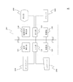
図1を参照して、本発明の実施の形態に係る音響諸室設計システムXの制御構成について説明する。
音響諸室設計システムXは、主に、PC100、3Dスキャナ200、入力デバイス300、表示部400、プリンタ500などから構成される。
PC100は、PC(パーソナル・コンピュータ)である通常のPC/AT互換機やMAC規格のPCであり、本発明の実施の形態に係る音場調整方法の演算を行うことができる構成部位である。PC100は、各種データを入力する入力部110(入力手段)、入力されたデータや予測モデル式や予測結果等を記憶する記憶部120(記憶手段)、後述する柱状反射体の直径を算出するための演算器等である直径算出部130(直径算出手段)、柱状反射体の配置条件を算出するための演算器等である配置条件算出部140(出力値算出手段)、CPU(セントラル・プロセッシング・ユニット、中央処理装置)やMPU(マイクロ・プロセッシング・ユニット)等である制御部150、演算により算出した結果を出力する出力部160とを主に備えている。
3Dスキャナ200は、レーザ等を使用した公知の3D(三次元)スキャナであり、音響諸室の主に中央に置くことで、音響諸室の部屋の立体的な構造や壁面までの正確な距離等を3Dデータに変換することができる。この3Dスキャナとしては、公知の、例えば、米国ファロー社製のレーザースキャナ(「http://www.faro.com/default.aspx?ct=jp」等を参照)等を用いることができる。
入力デバイス300は、キーボード、マウス等のポインティングデバイス、タッチパネル等のユーザインタフェイスに関する構成部位である。
表示部400は、一般的なLCDディスプレイやプラズマディスプレイや有機EL(エレクトロ・ルミネッセンス)ディスプレイやその他のディスプレイ装置である。また、表示部400は、部屋の構造について液晶シャッター方式やホログラム方式等で立体的に表示するようにしてもよい。
プリンタ500は、一般的なプリンタやXYプロッタ等のプリント装置である。また、プリンタ500には、フラッシュメモリカードリーダ/ライタ等を備えて、設計図や柱状反射体の直径と配置等を記憶できるようにしてもよい。<First Embodiment>
(Control configuration)
With reference to FIG. 1, the control structure of the acoustic room design system X which concerns on embodiment of this invention is demonstrated.
The acoustic room design system X mainly includes a
The
The
The
The
The
PC100について、さらに具体的に説明する。
入力部110は、3Dスキャナや入力デバイス300やLANインターフェイスやフラッシュメモリカードリーダやDVD−ROM等の入力手段からの入力を行うI/O等である。これにより、入力部110は、3Dスキャナ200からの音響諸室の測定データや、予め測定員が設定した音響諸室の設計図等のデータを入力することができる。
記憶部120は、RAMやROMやフラッシュメモリやHDD(ハード・ディスク・ドライブ)等である。記憶部120は、3Dスキャナ200から入力されたデータや、設計図等のデータや、本発明の実施の形態に係る音場調整方法のプログラムや、これに必要なパラメータ等のデータを記憶する。
直径算出部130は、専用の演算用DSP(デジタル・シグナル・プロセッサ)や物理演算専用演算装置やGPU(Graphics Processing Unit)等のリアルタイムに演算可能な演算器であり、柱状反射体の直径を算出する。
配置条件算出部140も、専用の演算用DSPや物理演算専用演算装置やGPU等のリアルタイムに演算可能な演算器である。配置条件算出部140は、柱状反射体の最適な配置条件について算出する。
制御部150は、実際に以下の騒音判定処理を行う際の制御と演算を行う部位である。制御部150は、記憶部120のROMやHDD等に記憶しているプログラムに従って、各種の制御と演算の処理を実行する。
出力部160は、表示部400やプリンタ500等の出力手段に出力を行うI/O等である。出力部160は、設計された音響諸室の構造や設計図を出力することができる。また、柱状反射体の直径と配置条件である柱状反射体構造物の設計図等についても、出力することができる。また、出力部160は、オーディオI/Oも備えており、後述するシミュレーションにて、実際の音の聞こえ方をシミュレートして出力することも可能である。
なお、直径算出部130と配置条件算出部140の機能は、制御部150の演算機能を用いて実現してもよい。The
The
The
The
The arrangement condition calculation unit 140 is also a computing unit capable of computing in real time, such as a dedicated computing DSP, a physical computing dedicated computing device, or a GPU. The arrangement condition calculation unit 140 calculates the optimum arrangement condition of the columnar reflector.
The
The
Note that the functions of the
〔音場調整方法〕
ここで本発明の実施の形態に係る音場調整方法の概要について説明する。
上述のように、限られた空間の中に作らざるをえない音響諸室では、施工するための背後の空間は限られている。このため、音響設計、音響施工による音場調整を行い、反射する壁と吸音する壁を組み合わせて、適度な響きのある空間とする必要がある。
しかしながら、人工的に作られた音響諸室における室内の音場(音響環境)では、特に高域の吸音過多に起因する閉塞感、低域の吸音が十分でないことに起因する低域の不明瞭感などが問題となる。[Sound field adjustment method]
Here, an outline of the sound field adjustment method according to the embodiment of the present invention will be described.
As described above, in the acoustic rooms that must be created in a limited space, the space behind the work is limited. For this reason, it is necessary to adjust the sound field by acoustic design and acoustic construction, and to combine the reflecting wall and the sound absorbing wall to make a space with appropriate sound.
However, in the sound fields (acoustic environment) in artificially created acoustic rooms, the low-frequency ambiguity caused by the high-frequency sound absorption and the low-frequency sound absorption is not sufficient. Feeling is a problem.
本発明の発明者らは、これらの音響諸室における音場の問題点を解決するため、鋭意検討と実験を行った。
そして、本発明の発明者らは、音響諸室内の響きの不自然さを解消するために、直径の異なる複数の柱状の反射体(柱状反射体)を組み合わせることが好適であることを見いだした。なお、本発明の柱状反射体は、本発明が奏する効果を得ることができる範囲において、任意の形状の音の拡散、反射、又は吸収を行う反射体を用いることができる。
本発明の実施の形態に係る音場調整方法においては、それらの柱状反射体について、周波数と波長の関係等から直径を算出し、音響諸室内の配置条件についても算出する。
具体的には、まず、ターゲットとする周波数帯域の音波を効果的に拡散する柱状反射体の直径を算出する。ここで、拡散とは、周波数帯域が異なる音波の反射方向及び/又は反射時間遅れ(位相)がランダムに反射することをいう。
この上で、高域を拡散させるために、音源に対して近く(内側、手前)に細い直径の柱状反射体を設置し、拡散せずに回折して回り込んだ低音を拡散や吸音させるために、音源に対して遠く(壁側、背後)に太い直径の柱状反射体の設置するように、配置条件を算出する。
その算出した直径と配置条件の音場調整方法を用いて施工することで、音響諸室内で、低域から高域に及ぶ広い周波数領域において、自然な音場を実現することが可能となる。
以下、図2のフローチャートを参照して、実際の音響諸室設計システムXの動作について、より詳しく説明する。
音響諸室設計システムXの動作の手順としては、まず、PC100が起動して、記憶部120に記憶された音場調整方法のプログラムを実行開始する。The inventors of the present invention have conducted intensive studies and experiments in order to solve the problems of the sound field in these acoustic rooms.
The inventors of the present invention have found that it is preferable to combine a plurality of columnar reflectors (columnar reflectors) having different diameters in order to eliminate the unnaturalness of the sound in the acoustic chambers. . In addition, the columnar reflector of this invention can use the reflector which carries out the spreading | diffusion of the arbitrary shapes, reflection, or absorption in the range which can acquire the effect which this invention show | plays.
In the sound field adjustment method according to the embodiment of the present invention, the diameter of these columnar reflectors is calculated from the relationship between the frequency and the wavelength, and the arrangement conditions in the acoustic chambers are also calculated.
Specifically, first, the diameter of a columnar reflector that effectively diffuses sound waves in a target frequency band is calculated. Here, the diffusion means that the reflection direction and / or reflection time delay (phase) of sound waves having different frequency bands are reflected randomly.
On top of this, in order to diffuse the high frequencies, a columnar reflector with a narrow diameter is installed close to the sound source (inside and in front) to diffuse and absorb the low frequencies diffracted without diffusing. In addition, the arrangement condition is calculated so that the columnar reflector having a large diameter is disposed far from the sound source (on the wall side and behind).
By constructing using the sound field adjustment method of the calculated diameter and arrangement conditions, it is possible to realize a natural sound field in a wide frequency range from low to high in the acoustic rooms.
Hereinafter, the operation of the actual acoustic room design system X will be described in more detail with reference to the flowchart of FIG.
As an operation procedure of the acoustic room design system X, first, the
(ステップS101)
入力部110は、3Dスキャナ200や、入力デバイス300から、本発明の実施の形態に係る音場調整を行うためのデータやパラメータを入力する。
入力するデータとしては、音響諸室の形状等の三次元データ等を用いる。入力するパラメータとしては、音響諸室の広さ等のパラメータ、配置条件設定用パラメータ、ターゲット周波数、柱状反射体の直径の設定用パラメータ、反射波の大きさ等のパラメータ等である。(Step S101)
The
As the input data, three-dimensional data such as the shape of the acoustic rooms is used. The input parameters include parameters such as the size of various acoustic rooms, parameters for setting the arrangement conditions, target frequencies, parameters for setting the diameter of the columnar reflector, and parameters such as the magnitude of the reflected wave.
音響諸室の広さ等のパラメータとして、3Dスキャナ200を用いて音響諸室の形状の三次元データを入力する際には、実際に施工する部屋の中央に設置した機器からレーザ等を照射して、その反射された時間等から三次元座標値を得る。
さらに、三次元データとして、LANインターフェイスやフラッシュメモリカードやDVD−R等の記憶媒体から、DXFファイル等のCADファイルを入力してもよい。
なお、音響諸室の三次元データの代わりに、より単純に、ユーザが入力デバイス300により音響諸室の縦幅、横幅、高さについて打ち込んだ値を検知して、音響諸室の広さ等のパラメータを入力することもできる。三次元データにスケール(広さ)の設定がない場合も、同様に広さ等のパラメータを入力できる。When inputting the three-dimensional data of the shape of the acoustic rooms using the
Furthermore, a CAD file such as a DXF file may be input as a three-dimensional data from a storage medium such as a LAN interface, a flash memory card, or a DVD-R.
In addition, instead of the three-dimensional data of the acoustic rooms, more simply, the user inputs values for the vertical width, horizontal width, and height of the acoustic rooms using the
配置条件設定用パラメータについては、柱状構造体を何列(段)構成にするか、又は列構成にしないか、吸音層を備えるか、壁面から何cmを柱状反射体構造物用に使用するか、等のパラメータを設定できる。ここでは、三次元データの座標で指定する領域ごとに、これらの配置条件設定用パラメータを設定することができる。たとえば、各面について座標として指定し、後壁の面を第1〜3列の構成にし、側壁の面は第1〜4列の構成にするといったことが可能である。また、柱状反射体は、重力方向に対してどのような方向でも設置可能なので、XYZ軸方向の角度についても指定可能である。さらに、梁を備えるか、オープンエンド(設置する片面のみ設置する)か、柱の端部を
天井と床の両方に設置するか、天井から吊すかといった設置方法についても選択可能である。加えて、後述する柱状反射体の設置のバラけ具合であるランダム配置度について設定できる。また、設置した際に柱状構造体の長さ方向と垂直方向の投影面で、背後が見通せる割合等についても設定できる。
ターゲット周波数については、後述する柱状反射体がターゲットとする周波数を設定可能である。この際、例えば、各柱状反射体構造物の列毎にターゲット周波数を設定できる。すなわち、2列の場合は、「高域(高音域)」と「中・低域(中音域、低音域)」の2種類の周波数を、それぞれ1000Hz、500Hzというように、パラメータとして与えることができる。また、音響諸室の三次元データ、音響諸室の広さ等のパラメータ、配置条件設定用パラメータ等に従って、ターゲット周波数の最適な値を算出することもできる。
柱状反射体の直径の設定用パラメータについては、上述のターゲット周波数に従って直径を算出するか、所定の直径が選択されたときの各ターゲット周波数を算出するか等についてパラメータを設定できる。
また、周波数帯域毎の音響特性について、周波数帯域毎の拡散効果を一定にするか、ターゲット周波数毎に異なるようにするかについてもパラメータとして設定することが可能である。As for the parameter for setting the arrangement condition, how many columns (stages) the columnar structure is to be arranged, whether it is not arranged in rows, whether it has a sound absorbing layer, how many cm from the wall surface is used for the columnar reflector structure , Etc. can be set. Here, these placement condition setting parameters can be set for each region specified by the coordinates of the three-dimensional data. For example, each surface can be designated as coordinates, the rear wall surface can be configured in the first to third columns, and the side wall surface can be configured in the first to fourth columns. Moreover, since the columnar reflector can be installed in any direction with respect to the direction of gravity, the angle in the XYZ axis direction can also be specified. Furthermore, it is possible to select an installation method such as providing a beam, open end (installing only one side to be installed), installing the column end on both the ceiling and the floor, or hanging from the ceiling. In addition, it is possible to set the degree of random arrangement, which is the degree of variation in the installation of columnar reflectors described later. In addition, the ratio of the back of the columnar structure that can be seen on the projection plane perpendicular to the length direction of the columnar structure can be set.
About the target frequency, the frequency which the columnar reflector mentioned later makes a target can be set. In this case, for example, the target frequency can be set for each column of the columnar reflector structures. That is, in the case of two rows, two frequencies, “high range (high range)” and “middle / low range (middle range, low range)”, can be given as parameters such as 1000 Hz and 500 Hz, respectively. it can. It is also possible to calculate the optimum value of the target frequency according to the three-dimensional data of the acoustic rooms, the parameters such as the size of the acoustic rooms, the arrangement condition setting parameters, and the like.
As for the parameter for setting the diameter of the columnar reflector, the parameter can be set as to whether to calculate the diameter according to the above-described target frequency, or to calculate each target frequency when a predetermined diameter is selected.
In addition, regarding the acoustic characteristics for each frequency band, it is possible to set as a parameter whether the diffusion effect for each frequency band is constant or different for each target frequency.
これらのパラメータに加えて、柱状反射体の材質や種類についてもパラメータとして設定することができる。柱状反射体の材質としては、消防法のため不燃木がデフォルト(標準)設定されている。これは、不燃木は、適度な内部損失があり、音響的にも優れているためである。
他に、柱状反射体の材質としては、金属やプラスチック(樹脂)等を用いることも当然可能である。金属の場合は、内部損失が高い合金等や制震合金等の金属を用いることができる。プラスチックの場合は、塩化ビニルやアクリル樹脂等を用いることができる。
また、中空の金属の内部に吸音素材を充填するか、制震シート等を貼り付けることもできる。これらの方法で、金属自体の共振がおきにくいようにすることが好適である。
プラスチックの場合も同様に、共振がおきにくい樹脂の素材を選択し、制震処理をした方がよい。
また、柱状反射体内部空間を利用した吸音機構により、音響諸室の定在波対策に用いることもできる。In addition to these parameters, the material and type of the columnar reflector can also be set as parameters. As the material of the columnar reflector, non-combustible wood is set as a default (standard) for the Fire Service Act. This is because incombustible wood has moderate internal loss and is acoustically superior.
In addition, as a material of the columnar reflector, it is naturally possible to use metal, plastic (resin), or the like. In the case of a metal, a metal such as an alloy having a high internal loss or a damping alloy can be used. In the case of plastic, vinyl chloride, acrylic resin, or the like can be used.
Moreover, a sound-absorbing material can be filled in a hollow metal, or a damping sheet or the like can be attached. With these methods, it is preferable to make the metal itself less likely to resonate.
Similarly, in the case of plastics, it is better to select a resin material that does not resonate easily and perform vibration control.
In addition, the sound absorbing mechanism using the internal space of the columnar reflector can be used as a countermeasure against standing waves in various acoustic rooms.
さらに、柱状反射体の主に断面の形状についても、パラメータとして設定することができる。
柱状反射体の断面の形状は、標準設定では円柱になっており、これが好適である。本発明の発明者が鋭意検討したところ、角柱のような平面で構成された反射面を有すると、反射波が、音波の入射方向に依存することがあるためである。すなわち、面で構成された柱を用いると、その面に対して十分に小さい波長の音波に対しては鏡面反射となり、音波の反射に方向性がつきやすいため、音場の特性のバラツキを生じやすい。
これに対して、円柱であれば、直径に比例した周波数以上の音波を、ほぼ理想的に再放射できる。これにより、より広いエリアに均一な拡散音を返すことができる。
なお、断面形状は円柱の他に、楕円柱であっても音響的に良好な特性が得られる。すなわち、音響的な拡散面、反射面、及び/又は吸収面が曲面状であることが好ましい。また、任意の形状の音の拡散、反射、及び/又は吸収を行う反射体であれば、音響的な拡散面、反射面、及び/又は吸収面が曲面状又は球面状であることが好ましい。Further, the shape of the cross section of the columnar reflector can also be set as a parameter.
The cross-sectional shape of the columnar reflector is a cylinder by default, which is preferable. The inventors of the present invention diligently studied, because the reflection wave may depend on the incident direction of the sound wave when it has a reflection surface constituted by a plane like a prism. In other words, if a pillar composed of a surface is used, a sound wave having a sufficiently small wavelength with respect to the surface will be mirror-reflected, and the direction of the sound wave will be easily reflected, resulting in variations in the characteristics of the sound field. Cheap.
On the other hand, if it is a cylinder, the sound wave more than the frequency proportional to the diameter can be re-radiated almost ideally. Thereby, a uniform diffused sound can be returned to a wider area.
It should be noted that, even if the cross-sectional shape is an elliptical cylinder in addition to a cylinder, good acoustic characteristics can be obtained. That is, the acoustic diffusing surface, reflecting surface, and / or absorbing surface are preferably curved. Moreover, if it is a reflector that diffuses, reflects, and / or absorbs sound having an arbitrary shape, the acoustic diffusing surface, reflecting surface, and / or absorbing surface is preferably curved or spherical.
また、選択する柱状反射体の形状としては、必ずしも完全な円柱ではなく、間伐材を使った場合のように節が残っていてもよい。また、実際の樹木のように枝葉のような構造があってもよい。また、反射体の形状としては、玉串のようなランダムに球状体を組合わせた形状、楕円体や球体そのもの等であってもよい。
また、同様の理由で、例えば、「エンタシス」のような中央が膨らんだ柱や、ボウリングのピンや、コカ・コーラ(登録商標)の容器のような形状であってもよい。このような形状とすると、より3次元的な拡散効果を得られる。In addition, the shape of the columnar reflector to be selected is not necessarily a complete cylinder, and nodes may remain as in the case of using thinned wood. Moreover, there may be a structure like a branch and leaf like an actual tree. Further, the shape of the reflector may be a shape in which spherical bodies are randomly combined such as a ball skewer, an ellipsoid, a sphere itself, or the like.
For the same reason, for example, it may be a shape such as a pillar with an inflated center such as “Enterasis”, a bowling pin, or a Coca-Cola (registered trademark) container. With such a shape, a three-dimensional diffusion effect can be obtained.
また、上述の理由にもかかわらず、施工上の問題等を鑑みて、四角柱や三角柱のような多角形についても選択できる。この場合には、円柱や楕円柱とは違った特別の音響効果を得ることができる。たとえば、自己相似性をもったフラクタル図形を用いて、拡散性の優れた特性をもった多面体を用いることもできる。好ましくは、反射体は、互いに並行面が生じないように配置される。
なお、これらの複雑な形状は、3Dスキャナ200から、又はCAD用のDXFファイル等を用いて入力することができる。In addition, in spite of the above-mentioned reasons, it is possible to select a polygon such as a quadrangular prism or a triangular prism in view of construction problems. In this case, it is possible to obtain a special acoustic effect different from that of a cylindrical or elliptical cylinder. For example, a polyhedron having excellent diffusibility can be used by using a fractal graphic having self-similarity. Preferably, the reflectors are arranged so that parallel planes do not occur.
These complex shapes can be input from the
また、柱状反射体の表面の音響インピーダンス、パラメータとして設定することが可能である。これは、一般的なラッカー塗装とウレタン系の塗装では、音波の反射率が異なるためである。
さらに、デザインを向上させるパラメータとして、塗装の濃さに関しては、壁側(奥)に設置された直径が大きい柱状反射体については濃い色に塗装し、表側については薄い色に塗装することで、奥行き感を演出することができる。
入力されたパラメータは、入力部110が記憶部120に記憶する。Moreover, it is possible to set the acoustic impedance and parameters of the surface of the columnar reflector. This is because the reflectance of sound waves differs between general lacquer coating and urethane coating.
Furthermore, as a parameter to improve the design, with regard to the darkness of the coating, the columnar reflector with a large diameter installed on the wall side (back) is painted in a dark color, and the front side is painted in a light color, A sense of depth can be produced.
The
(ステップS102)
次に、直径算出部130が、入力されたパラメータに従って、柱状反射体の直径を算出する。また、所定の直径を選択されている場合は、ターゲット周波数を算出する。
ここで、音波は、円柱にあたると単純に反射をせず、入射方向とは関係ない拡散波としてあらゆる方向に再放射(又は拡散)することがある。
その際、円柱の直径により、再放射(又は拡散)しやすい周波数帯域が決まる。直径が小さいほど高い周波数の音波を再放射し、逆に直径が大きいほど低い周波数の音波まで再放射できる。これらの再放射に係わる周波数帯域を、ここでは「ターゲット周波数」とする。
なお、直径が大きい円柱に高い周波数の音波を当てると、拡散はするものの、一様に再放射する訳ではなく、指向性が鋭くなる。すなわち、放射する方向が均等でなくなるため、直径と周波数帯域の関係には、最適な範囲が存在する。(Step S102)
Next, the
Here, the sound wave is not simply reflected when it hits the cylinder, and may be re-radiated (or diffused) in all directions as a diffuse wave not related to the incident direction.
At this time, the frequency band that is likely to be re-radiated (or diffused) is determined by the diameter of the cylinder. The smaller the diameter, the higher frequency sound waves can be re-radiated, and the larger the diameter, the lower frequency sound waves can be re-radiated. These frequency bands related to re-radiation are herein referred to as “target frequencies”.
When a high-frequency sound wave is applied to a cylinder with a large diameter, although it diffuses, it does not re-radiate uniformly, but the directivity becomes sharp. That is, since the radiating direction is not uniform, there is an optimum range in the relationship between the diameter and the frequency band.
一方、ターゲット周波数以下の周波数は、通常は再放射されずに回折するように背後に回り込む。本発明の発明者は、このような性質を用いて、音場の調整を行うことが可能であることに気がついた。
本発明の実施の形態に係る音場調整方法においては、入射した音波が、音響諸室内に拡散するように、柱状反射体の直径を算出する必要がある。
このため、上述の入力したパラメータと、後述する配置条件に即したターゲット周波数を基に、柱状反射体の直径を算出する。On the other hand, frequencies below the target frequency usually wrap around behind so that they are diffracted without being re-radiated. The inventor of the present invention has realized that the sound field can be adjusted using such a property.
In the sound field adjustment method according to the embodiment of the present invention, it is necessary to calculate the diameter of the columnar reflector so that the incident sound wave diffuses into the acoustic chambers.
For this reason, the diameter of the columnar reflector is calculated on the basis of the input parameters described above and the target frequency in accordance with the arrangement conditions described later.
直径の算出について、より具体的に説明する。
柱状反射体の直径としては、従来より、円筒に音波が入射した場合の解析が行われているため、これを利用することができる(例えば、音響工学原論、「http://www.acoust.rise.waseda.ac.jp/publications/onkyou/genron−4.pdf」を参照)。
半径がaなる円筒に平面波の音波が入射したときに、この平面波が円筒から輻射される散乱波エネルギー流(W)は、円筒の単位長ごとに、以下の式(1)のようになる:The calculation of the diameter will be described more specifically.
As the diameter of the columnar reflector, since analysis when a sound wave is incident on a cylinder has been conventionally performed, this can be used (for example, acoustic engineering theory, “http: //www.acoust. rise.waseda.ac.jp/publications/onkyo/genron-4.pdf ").
When a plane wave sound wave is incident on a cylinder having a radius a, the scattered wave energy flow (W) radiated from the cylinder is expressed by the following equation (1) for each unit length of the cylinder:

一方、円筒の単位長に入射する平面波エネルギー流(W0)は、以下の式(2)のようになる:On the other hand, the plane wave energy flow (W 0 ) incident on the unit length of the cylinder is represented by the following equation (2):
よって、円筒の単位長に入射した平面波エネルギーが散乱される割合(比率)は、以下の式(3)のようになる: Therefore, the ratio (ratio) at which the plane wave energy incident on the unit length of the cylinder is scattered is expressed by the following equation (3):
これらの式(1)〜(3)により、例えば直径0.4m(半径が0.2m)の円柱の場合、約175Hzより高い周波数の音エネルギーは、円筒の単位長当りに入射した平面波エネルギー流は、円筒によってほぼ100%散乱される。
よって、入射波エネルギーが円筒によって散乱される割合がほぼ1となるような、下限周波数と円筒の直径との関係は、以下の表1のようになる。According to these formulas (1) to (3), for example, in the case of a cylinder having a diameter of 0.4 m (radius is 0.2 m), the sound energy having a frequency higher than about 175 Hz is a plane wave energy flow incident per unit length of the cylinder. Is almost 100% scattered by the cylinder.
Therefore, the relationship between the lower limit frequency and the diameter of the cylinder so that the ratio of the incident wave energy scattered by the cylinder is approximately 1 is as shown in Table 1 below.
よって、直径32mmでは2183Hz以上、直径45mmでは1553Hz以上、直径60mmでは1165Hz以上、といったように、入射音波に対して、円筒の直径に応じた周波数以上の音エネルギーを散乱させることができる。 Therefore, it is possible to scatter sound energy having a frequency higher than the frequency corresponding to the diameter of the cylinder, such as 2183 Hz or more at a diameter of 32 mm, 1553 Hz or more at a diameter of 45 mm, and 1165 Hz or more at a diameter of 60 mm.
しかしながら、実際には散乱される割合が1以下であっても、拡散効果が得られる。
このため、本発明の実施の形態に係る音場調整方法においては、例えば、高音域用に1000Hz以上をターゲット周波数とする場合は、直径30〜75mmと算出する。
また、例えば、中音域又は低音域用に約630Hz以上をターゲット周波数とする場合は、直径60〜120mmと算出する。
更に、例えば、低音域用に約500Hz以上をターゲット周波数とする場合は、直径80〜160mmと算出する。However, even if the scattering ratio is actually 1 or less, a diffusion effect can be obtained.
For this reason, in the sound field adjustment method according to the embodiment of the present invention, for example, when the target frequency is 1000 Hz or more for the high sound range, the diameter is calculated as 30 to 75 mm.
For example, when the target frequency is set to about 630 Hz or more for the mid range or the low range, the diameter is calculated as 60 to 120 mm.
Further, for example, when the target frequency is about 500 Hz or more for the low sound range, the diameter is calculated as 80 to 160 mm.
これにより、例えば、柱状反射体を2列配置し、高音域用に1000Hz、中・低域用に500Hzを対象とする場合には、それぞれ直径が40mmと、100mmとを柱状反射体の直径として用いるように算出することができる。
これに加えて、500Hz以下の低音域用に、さらに直径の大きな柱状反射体を用いることも可能である。この場合は、音響諸室の大きさや性質(録音スタジオか、ホールか、等)により、最適なターゲット周波数を設定して、それに即した直径を算出できる。たとえば、音響諸室が録音スタジオで、7m(幅)×4m(奥行き)×3m(高さ)程度の広さである場合は、直径150mm等とすることができる。Thus, for example, when two columnar reflectors are arranged and the target is 1000 Hz for a high sound range and 500 Hz for a middle / low range, the diameters of the columnar reflectors are 40 mm and 100 mm, respectively. Can be calculated to use.
In addition, it is also possible to use a columnar reflector having a larger diameter for a low frequency range of 500 Hz or less. In this case, an optimum target frequency can be set according to the size and properties of the acoustic rooms (recording studio, hall, etc.), and the diameter corresponding to the target frequency can be calculated. For example, when the acoustic rooms are a recording studio and are about 7 m (width) × 4 m (depth) × 3 m (height), the diameter may be 150 mm.
また、逆に、所定の直径を用いる場合には、音波の反射面の周波数を算出して、これをターゲット周波数とすることもできる。
たとえば、規格材の直径を使う場合、高音域(ターゲット周波数は、約2000Hz)用に直径20mm、中音域(ターゲット周波数は、約1000Hz)用に直径が45mm、低音域(ターゲット周波数は、約630Hz)用に直径が60mmといった柱状反射体を用いて3列配置するように算出することができる。
このステップで算出された直径(や、ターゲット周波数)は、次のステップで配置条件の算出の際に使用する。Conversely, when a predetermined diameter is used, the frequency of the sound wave reflecting surface can be calculated and used as the target frequency.
For example, when using the diameter of a standard material, the diameter is 20 mm for the high sound range (target frequency is about 2000 Hz), the diameter is 45 mm for the mid sound range (target frequency is about 1000 Hz), and the low sound range (target frequency is about 630 Hz). 3) using a columnar reflector having a diameter of 60 mm.
The diameter (or target frequency) calculated in this step is used when calculating the arrangement condition in the next step.
(ステップS103)
次に、配置条件算出部140が、入力されたパラメータと上述の直径に従って、柱状反射体の配置条件を算出する。
本発明の実施の形態に係る音場調整方法によると、(a)手前(音源からみて内側)に、直径が細い柱状反射体を配置し、背後には直径が太い柱状反射体を配置することと、(b)各列につき周期性を回避してランダムな間隔で配置する、ことが特徴である。(Step S103)
Next, the arrangement condition calculation unit 140 calculates the arrangement condition of the columnar reflectors according to the input parameters and the above-described diameter.
According to the sound field adjustment method according to the embodiment of the present invention, (a) a columnar reflector with a small diameter is arranged in front (inside of the sound source), and a columnar reflector with a large diameter is arranged behind. (B) Each column is characterized by being arranged at random intervals while avoiding periodicity.
(a)の直径が細い柱を手前に配置することに関しては、逆に太い柱状反射体を手前にすると、音響的に好ましくないためである。これは、直径が太い柱状反射体は、より低い周波数では上述のように拡散するものの、高い周波数の音の波面は、拡散する方向が均一でなくなり、指向性が強くなるためである。
よって、本発明の実施の形態に係る音場調整方法によれば、音源からみて手前に高域用に細い柱状反射体を設置して高域の音波を拡散させるようにする。
これにより、柱状反射体の音響抵抗(インピーダンス)を緩やかに変化させ、レベルの大きな反射が拡散体の表面で起こることを回避することができる。
(b)の各列についてランダムに配置することに関しては、規則的な配列に係る特定周波数のカラレーション(coloration、音色の変化)を回避することができるためである。このカラレーションについては、後述の実施例で詳しく説明する。Concerning disposing a column with a thin diameter (a) in front, it is acoustically undesirable to have a thick columnar reflector in front. This is because the columnar reflector having a large diameter diffuses at a lower frequency as described above, but the wave front of the high frequency sound does not have a uniform direction of diffusion and becomes more directional.
Therefore, according to the sound field adjustment method according to the embodiment of the present invention, a thin columnar reflector is installed in front of the sound source to diffuse the high frequency sound wave.
As a result, the acoustic resistance (impedance) of the columnar reflector can be gently changed, and a large level of reflection can be avoided from occurring on the surface of the diffuser.
This is because the arrangement of each row in (b) at random can avoid the coloration (coloration, change in timbre) of the specific frequency related to the regular arrangement. This coloration will be described in detail in an example described later.
まずは、反射音をきめ細かく拡散させるため、手前には細い柱をランダムな間隔で配置する。奥に行くに従って柱の径を太くし、最後列には最も太い柱を、これもランダムな間隔で配置する。
これにより、音響的に好ましく、カラレーションの少ない音場環境を得ることができる。
より詳しい配置条件について、以下で説明する。First, in order to diffuse the reflected sound finely, thin columns are arranged at random intervals in front. As you go deeper, the diameter of the pillars increases, and the thickest pillars in the last row are also arranged at random intervals.
As a result, a sound field environment that is acoustically preferable and has little coloration can be obtained.
More detailed arrangement conditions will be described below.
〔円柱の本数、列内の柱間隔、列と列の間隔の算出〕
実際の柱状反射体の本数、列内の間隔、列と列の間隔等について算出については、柱の長さ方向に対して垂直方向の断面の投影面について、単位面積当たりの柱の断面積(密度)を基準とすることができる。また、柱の長さ方向に対して垂直の方向への投影面について、単位投影面積当たりの柱の断面積(開口率)を、柱状反射体の列毎に算出することもできる。これらの断面積の違いが10%未満になるように、柱の本数、列と列の間隔を設定することもできる。[Calculation of the number of cylinders, the spacing between columns, the spacing between rows]
For the calculation of the actual number of columnar reflectors, the interval between columns, the interval between columns, etc., the column cross-sectional area per unit area (with respect to the projection plane of the section perpendicular to the column length direction) Density). Further, with respect to the projection plane in the direction perpendicular to the length direction of the column, the cross-sectional area (aperture ratio) of the column per unit projection area can be calculated for each column of the columnar reflectors. The number of columns and the interval between columns can be set so that the difference in cross-sectional area is less than 10%.
柱の長さ方向に対して垂直の方向への投影面について、単位投影面積当たりの柱の断面積(開口率)を、直径の違う柱状反射体の列毎にほぼ一定にすることにより、柱状反射体による拡散効果の周波数毎のばらつきを少なくするという効果が得ることができる。
これとは逆に、ターゲット周波数によって拡散効果を変化させる場合は、単位投影面積当たりの柱の断面積(開口率)が、直径の違う柱状反射体の列毎に変化するように、各直径の列毎に柱の間隔を変化させることで制御可能である。By making the cross-sectional area (aperture ratio) of the column per unit projected area almost constant for each column of columnar reflectors with different diameters on the projection plane in the direction perpendicular to the length direction of the column The effect of reducing the dispersion | variation for every frequency of the diffusion effect by a reflector can be acquired.
On the contrary, when the diffusion effect is changed depending on the target frequency, the cross-sectional area (aperture ratio) of the column per unit projected area changes for each column of columnar reflectors having different diameters. It can be controlled by changing the interval between the columns for each column.
列内の柱状反射体の間隔は、周期的なピッチで配置されると、配列ピッチに応じた周期で特異な反射性状となり、特定の周波数の音が強調されたりする「カラレーション」が起こりやすくなるため、これらの悪影響が起こらないように、ランダムに配置する。 When the intervals between the columnar reflectors in the row are arranged at a periodic pitch, the reflection becomes a unique reflection property with a period corresponding to the arrangement pitch, and “coloration” in which sound of a specific frequency is emphasized easily occurs. Therefore, it arranges at random so that these bad influences may not occur.
ランダムな配置を実現する方法の例としては、以下の手順があげられる。
(1)例えば、最初に半径の違う円柱を3種類程度用意する。ここで 大、中、小の半径をそれぞれa、b、cとする。
(2)次に各大きさの円柱を列状に等間隔に並べる。その円柱中心の間隔は、大きい円柱の場合u は2a<u、中位の円柱の場合vは2b<v、小さい円柱の場合wは2c<wとする。
(3)その大中小の円柱の列を平行配置する。大中の円柱の列の中心を通る線の距離dをa+b<d、中小の円柱の列の中心を通る線の距離eをb+c<eとする。
(4)それぞれの円柱の位置を列方向や列間方向に移動させる。その実現方法は、例えば−0.5から0.5の間の一様乱数を発生させ、円柱同士の中心間距離から円柱の半径を差し引いた値(大きい円柱の列方向の場合はu−2a、大きい円柱の列と中位の円柱の間の方向の場合はd−(a+b)などとなる)にかけて得られた値の距離を移動させる。The following procedure is mentioned as an example of the method of implement | achieving random arrangement | positioning.
(1) For example, first, about three types of cylinders with different radii are prepared. Here, the large, medium, and small radii are a, b, and c, respectively.
(2) Next, cylinders of various sizes are arranged in a line at regular intervals. The distance between the centers of the cylinders is 2a <u for a large cylinder, 2b <v for a middle cylinder, and 2c <w for a small cylinder.
(3) The large, medium, and small columns are arranged in parallel. The distance d of the line passing through the center of the column of large and medium cylinders is a + b <d, and the distance e of the line passing through the center of the column of medium and small cylinders is b + c <e.
(4) The positions of the respective cylinders are moved in the row direction or the row-to-row direction. For example, a uniform random number between -0.5 and 0.5 is generated, and a value obtained by subtracting the radius of the cylinder from the center-to-center distance between the cylinders (u-2a in the case of a large cylinder column direction). In the case of the direction between the large column of cylinders and the middle column, it becomes d- (a + b) etc.), and the distance of the obtained value is moved.
なお、柱状反射体を列状(段状)に整列された配置の場合は、施工が簡単になるという効果が得られる。
また、いくつかの列についてのみ、ランダムな配置とするようにしてもよい。たとえば、施工するスペースに合わせ、500Hz以下をターゲット周波数とする低音域についてのみ、ランダムに配置するようにすることもできる。
また、柱状反射体は、周波数帯域毎に、直線ではなく曲線状の列状にすることも可能である。たとえば、映画館の場合は前方の左右・センタースピーカと後方からのサラウンドスピーカ群の設置に合わせて、後方に従って列状構造同士の間隔をが長くなるように設定することで、包み込むような音場を作成することができる。また、このような間隔の調整により、残響音の周波数帯域毎の到達時間を調整して、広い空間を演出することもできる。
これらの配置条件により、音響諸室の特性に合わせた音場の作成が可能になる。In the case where the columnar reflectors are arranged in rows (steps), an effect that the construction is simplified is obtained.
Further, only some columns may be randomly arranged. For example, according to the space to be constructed, it can be arranged randomly only in the low sound range with a target frequency of 500 Hz or less.
Further, the columnar reflector can be formed in a curved line instead of a straight line for each frequency band. For example, in the case of a movie theater, a sound field that wraps around by setting the distance between the row-like structures to be longer along the back in accordance with the setting of the front left / right / center speaker and the rear surround sound speaker group. Can be created. In addition, by adjusting the interval as described above, it is possible to produce a wide space by adjusting the arrival time of each reverberation sound for each frequency band.
These arrangement conditions make it possible to create a sound field that matches the characteristics of the acoustic rooms.
また、各直径の柱状反射体の列を多段配置した場合、柱状反射体の長さ方向と垂直方向の投影面で、背後が見通せる割合のパラメータに従って、各柱間の間隔を調整する。
デフォルト(標準設定)としては、例えば、柱状構造体の拡散効果を高めたい場合は柱の長さ方向に対して垂直方向で柱状反射体全体の投影面積が、全体の投影面積の95%以上となるようにするのがよい。すなわち、柱群により背後が見通せなくなる程度に、配置調整を行う。また、柱状反射体は、音源に近い方に低い占有密度及び/又は投影面積を形成し、より音源に対して遠くに高い占有密度及び/又は投影面積を形成することが好ましい。
これにより、柱状反射体の拡散されなかった音波が、背後の壁面で反射してくる影響を軽減することが可能になる。また、背後に壁面がない場合でも、直接背後を見通せないようにすることで、音場に悪影響を与えない仕切り代わりに用いることもできる。Further, when the columns of columnar reflectors of each diameter are arranged in multiple stages, the interval between the columns is adjusted according to the parameter of the ratio that the back can be seen on the projection plane perpendicular to the length direction of the columnar reflector.
As a default (standard setting), for example, when it is desired to increase the diffusion effect of the columnar structure, the projected area of the entire columnar reflector is 95% or more of the entire projected area in the direction perpendicular to the length direction of the column. It is good to be. That is, the placement adjustment is performed so that the back cannot be seen by the column group. The columnar reflector preferably forms a low occupation density and / or projection area closer to the sound source, and forms a higher occupation density and / or projection area farther from the sound source.
Thereby, it becomes possible to reduce the influence that the sound wave that has not been diffused by the columnar reflector is reflected by the wall surface behind. Moreover, even when there is no wall surface behind, it can be used instead of a partition that does not adversely affect the sound field by making it impossible to look directly behind.
さらに、上述のパラメータに従って、吸音層の配置の条件についても算出する。
柱状拡散体を上述の配置条件で配置すると、中高域の音は前列または中列の柱列により大部分が反射し、後列の背後に達するのは、主に低域の音である。
そこで、音響諸室の吸音状況に応じて、膜状の吸音層等を用いて、柱状反射体と吸音層との位置関係(位置の関係)により、周波数特性と拡散/吸音の関係や周波数帯域、反射方向、及び反射時間構造等を制御することができる。すなわち、特定の周波数の音が拡散される割合と吸音される割合をコントロールすることが可能である。
図3を参照して詳しく説明すると、壁面700に向かって手前から奥に、高音域用柱状構造体731の列と、中音域用柱状構造体732の列と、低音域用柱状構造体733の列とがある場合に、吸音層750(吸音体)を配置した場合の例について示す。吸音層750には、グラスウール、ロックウール、ウレタンフォーム、フェルト布地、音響透過性のある膜等を用いることができる。Furthermore, the conditions for the arrangement of the sound absorbing layer are also calculated according to the parameters described above.
When the columnar diffuser is arranged under the above-described arrangement conditions, most of the mid-high range sound is reflected by the front row or the middle row of columns, and it is mainly the low-frequency sound that reaches the back of the back row.
Therefore, depending on the sound absorption status of the acoustic rooms, the relationship between the frequency characteristics and diffusion / sound absorption and the frequency band are determined by the positional relationship (positional relationship) between the columnar reflector and the sound absorbing layer using a film-like sound absorbing layer. , Reflection direction, reflection time structure, and the like can be controlled. That is, it is possible to control the rate at which sound of a specific frequency is diffused and the rate at which sound is absorbed.
Describing in detail with reference to FIG. 3, from the front toward the back toward the
図3(a)の配置は、高音域用柱状構造体731の列と、中音域用柱状構造体732の列の間に吸音層750を挿入して配置した例である。このような配置の場合、高音域は拡散され、中・低音域の吸音量を増やすことができる。
図3(b)の配置は、中音域用柱状構造体732の列と、低音域用柱状構造体733の列の間に吸音層750を挿入して配置した例である。このような配置の場合、中・高音域は拡散され、低音域の吸音量と壁からの反射音の吸音量を増やすことができる。The arrangement of FIG. 3A is an example in which a
The arrangement in FIG. 3B is an example in which the
このように、吸音層を、柱状構造体との位置関係を基に設置することにより、音波の拡散と吸収を周波数帯ごとに調整することができる。よって、中・高域の吸音力を制御することもできる。すなわち、前列と中列の間、あるいは中列と後列の間のような、吸音層を配置する位置関係により、低域〜高域の拡散と吸音の関係を制御することができる。このため、中・高域の吸音力を過度に大きくすることなく、低域の吸音力を制御することが可能になる。
なお、吸音層750を高音用柱状構造体731より手前に配置すると、低音域〜高音域と壁面700からの反射音をすべて吸音させることができる。さらに、吸音層750が不透明な素材でできている場合、背後の柱状構造体を隠すことができる。
また、吸音層750を低音域用柱状構造体733の背後に配置すると、反射する低音域の吸音力を制御することができる。
さらに、吸音層750は、柱状反射体の群の中に任意に配置することができ、吸音特性や反射特性を任意に調整することができる。In this way, by installing the sound absorbing layer based on the positional relationship with the columnar structure, sound wave diffusion and absorption can be adjusted for each frequency band. Therefore, it is possible to control the sound absorption force in the middle / high range. That is, the relationship between low-frequency to high-frequency diffusion and sound absorption can be controlled by the positional relationship between the front row and the middle row or between the middle row and the rear row. For this reason, it is possible to control the sound absorption force in the low range without excessively increasing the sound absorption force in the middle / high range.
If the
In addition, when the
Furthermore, the
また、吸音層としては、膜状の形状ではなく、例えばフェルトやグラスウールのような素材を用いて吸音力を高めた柱状の吸音体を用いることも可能である。すなわち、膜状の吸音層を設置するよりも簡易に吸音させることもできる。 Further, as the sound absorbing layer, it is possible to use a columnar sound absorber whose sound absorbing power is increased by using a material such as felt or glass wool instead of a film shape. That is, it is possible to absorb sound more simply than to install a film-like sound absorbing layer.
さらに、直径と配置条件とを、音源から柱状反射体に至るまでの間の媒質の音響インピーダンスから柱状体内部における音響インピーダンスへの整合を図る反射面を形成することもできる。ここで、媒質とは、通常は空気である。 Furthermore, it is also possible to form a reflecting surface that matches the diameter and the arrangement condition from the acoustic impedance of the medium from the sound source to the columnar reflector to the acoustic impedance inside the columnar body. Here, the medium is usually air.
一般に、エネルギーの伝送をスムーズに行うには様々な工夫が必要である。
例えば、音響ホーンは、一種の音響的なインピーダンス変換装置であり、インピーダンスマッチングをとって音響振動源周辺の空気振動をホーン外部に効率よく伝える装置がある。また、同様に、吸音を目的とした吸音楔などは、伝達媒質(空気)中の音響インピーダンスから吸音楔を構成する多孔質材の音響インピーダンスへとインピーダンスの変換が行われるように楔形状を形成して、効率よく空気の振動エネルギーを多孔質材料中の摩擦熱エネルギーに変換していた。
これに対して、反射面が幾重にも重なって構成されている柱状反射体の奥部や背後部まで、効率よく伝搬媒質中から到来した空気振動を導くためには、インピーダンスをマッチングさせることが必要である。In general, various devices are required to smoothly transmit energy.
For example, an acoustic horn is a kind of acoustic impedance converter, and there is a device that takes impedance matching and efficiently transmits air vibration around an acoustic vibration source to the outside of the horn. Similarly, sound absorbing wedges for the purpose of sound absorption have a wedge shape so that the impedance is converted from the acoustic impedance in the transmission medium (air) to the acoustic impedance of the porous material constituting the sound absorbing wedge. Thus, vibration energy of air is efficiently converted into frictional heat energy in the porous material.
On the other hand, impedance can be matched to efficiently guide air vibrations coming from the propagation medium to the back and back of the columnar reflector, which is composed of multiple reflecting surfaces. is necessary.
本発明の実施の形態に係る音場調整方法によると、直径の小さい丸棒を表面側に配置する事から始まり、柱状反射体の背後部に至るにつれて段々丸棒の直径を大きくしていくことで、表面のインピーダンスから柱状反射体内部のインピーダンスのマッチングをとることができる。
また、丸棒の直径の大きさにとらわれず柱状反射体の表面側の開口率を大きく設定し、柱状反射体の背後部に至るにつれて開口率を小さくするこどで、インピーダンスのマッチングをとることもできる。
さらに、丸棒の占有断面積及び/又は体積密度を表面側から柱状反射体の背後部に至るにつれて順次増加させることで、インピーダンスのマッチングをとることもできる。According to the sound field adjustment method according to the embodiment of the present invention, a round bar having a small diameter is started on the surface side, and the diameter of the round bar is gradually increased toward the back of the columnar reflector. Thus, the impedance inside the columnar reflector can be matched from the surface impedance.
In addition, impedance matching is achieved by setting a large aperture ratio on the surface side of the columnar reflector regardless of the diameter of the round bar and decreasing the aperture ratio toward the back of the columnar reflector. You can also.
Furthermore, impedance matching can be achieved by sequentially increasing the occupied cross-sectional area and / or volume density of the round bar from the surface side to the back of the columnar reflector.
このように、本発明の実施の形態に係る音場調整方法は、インピーダンスのマッチングを行い、効率よく伝搬媒質中から到来した空気振動を導くことができる。
なお、インピーダンスのマッチングの詳細のための計算は、差分法プログラムなどを用いて行うこともできる。As described above, the sound field adjustment method according to the embodiment of the present invention can perform impedance matching and efficiently guide air vibrations coming from the propagation medium.
The calculation for details of impedance matching can also be performed using a difference method program or the like.
以上のように配置条件を設定することにより、限られた奥行き空間であっても、低域から高域に至る広い範囲で反射音をきめ細かく拡散させると同時に、有害で不自然な響きを取り除くことができる。また、周波数特性を調整することができる。
更に反射体内部の空間を利用し、ヘルムホルツ吸音機構や微小孔板吸音機構等による特定の周波数を対象とした吸音力を備えることができ、特に音響諸室の低域の定在波対策として効率の良い対策が可能となる。By setting the arrangement conditions as described above, even in a limited depth space, the reflected sound is finely diffused over a wide range from low to high, and at the same time, harmful and unnatural sound is removed. Can do. Further, the frequency characteristic can be adjusted.
In addition, the space inside the reflector can be used to provide sound absorption for specific frequencies by means of the Helmholtz sound absorption mechanism or the micro-hole plate sound absorption mechanism, which is particularly effective as a countermeasure against standing waves in the low frequencies of acoustic rooms. Good measures can be taken.
(ステップS104)
最後に、算出した柱状反射体の直径と配置条件とを入力した音響諸室のデータに適応して、音響諸室の配置・シミュレーション処理を行う。
このシミュレーション処理においては、反射音の時間波形を任意の測定点の座標で計測してグラフで出力するような処理を行うことができる。また、反射音のエネルギーの減衰についてもグラフを出力することが可能である。
このグラフの作成においては、音源からの直接波、複数の柱状反射体すべての反射及び壁面の反射によるすべての反射波を、設定した受音点で観測した時間応答を解析し、時間波形、エネルギー減衰(レベル減衰)、音圧分布の推移を算出する。
これらのグラフは、出力部160により、表示部400やプリンタ500へ出力することができる。(Step S104)
Finally, the acoustic chambers are arranged and simulated in accordance with the data of the acoustic chambers in which the calculated diameters and arrangement conditions of the columnar reflectors are input.
In this simulation process, it is possible to perform a process in which the time waveform of the reflected sound is measured at an arbitrary measurement point coordinate and output in a graph. It is also possible to output a graph for the attenuation of reflected sound energy.
In creating this graph, the time response of the direct wave from the sound source, the reflection of all of the columnar reflectors and the reflection of all of the reflections from the wall surface observed at the set sound receiving point is analyzed, and the time waveform and energy are analyzed. The transition of attenuation (level attenuation) and sound pressure distribution is calculated.
These graphs can be output to the
また、音響拡散体の直径や配置についての設計図についても、同様に出力することもできる。
この際に、例えば木のベース板を算出された直径と配置条件でくり抜くようにして、そこに柱状反射体を差し込むようにして製造するような、柱状反射体構造物の設計図についても出力することができる。
さらに、柱状反射体構造物を、音響諸室の壁に取り付けるモジュール状に加工するような設計図も作成することができる。Moreover, it can also output similarly about the blueprint about the diameter and arrangement | positioning of an acoustic diffuser.
At this time, for example, a plan view of a columnar reflector structure is also output such that a wooden base plate is cut out with a calculated diameter and arrangement condition and a columnar reflector is inserted therein. be able to.
Furthermore, it is possible to create a design drawing in which the columnar reflector structure is processed into a module attached to the walls of the acoustic rooms.
また、任意の音声をWAV(波形)ファイル等で指定するかマイクやライン入力等から入力して、実際の音響諸室の音響について聴いて確認することも可能である。その際は、ユーザが表示部400に表示されたGUI(グラフィカル・ユーザ・インタフェイス)にて、その音の発生点の座標と、評価点の座標を指定する。その上で、ユーザが表示部400に表示された「再生」ボタンを押下したことを制御部150で検知して、波形の再生を行う。これをGPU等を用いてリアルタイムで計算することで、実際に物理的に計算されたリバーブ機器として使用することも可能である。
なお、音源はデフォルト(標準設定)では全方向への点音源を用いるが、スピーカ等のシミュレーションとして方向を指定することもできる。さらに、評価点の耳の方向等も指定することができる。
さらに、柱状反射体を配置する位置を調整したり、壁面の厚さや音響諸室の形状を変更する等の操作も行うことができる。
加えて、各柱状反射体の材質や形状や塗装の濃さ等についても選択することが可能である。It is also possible to specify an arbitrary sound by a WAV (waveform) file or the like or input from a microphone or a line input and listen to and confirm the sound in the actual sound rooms. In that case, the user designates the coordinates of the sound generation point and the coordinates of the evaluation point using a GUI (graphical user interface) displayed on the
The sound source uses a point sound source in all directions by default (standard setting), but the direction can also be specified as a simulation of a speaker or the like. Furthermore, the direction of the ear of the evaluation point can be specified.
Furthermore, it is possible to perform operations such as adjusting the position where the columnar reflector is disposed, changing the thickness of the wall surface, and the shape of the acoustic rooms.
In addition, it is possible to select the material and shape of each columnar reflector, the darkness of the coating, and the like.
ユーザは、これらのグラフの出力や再生音を基に、更にパラメータを調整して直径や配置条件を算出し直し、配置・シミュレーションを行う。
これにより、柱状反射体を使用した音場調整方法により、カバ−エリアが広く周波数特性のバランスに優れた音響諸室を設計することができる。
そして、出力された設計図を用いて施工することで、実際の柱状反射体構造物の設置された音響諸室を製造することができる。Based on the output of these graphs and the reproduced sound, the user further adjusts the parameters, recalculates the diameter and placement conditions, and performs placement / simulation.
As a result, it is possible to design various acoustic rooms with a wide cover area and an excellent balance of frequency characteristics by a sound field adjustment method using a columnar reflector.
And by constructing using the output design drawing, it is possible to manufacture acoustic rooms in which actual columnar reflector structures are installed.
〔柱状反射体の配置のシミュレーションによる比較〕
以下で、本発明の実施の形態に係る音場調整方法について、柱状反射体の拡散効果を差分方で数値シミュレーションを用いてシミュレートした結果について説明する。このシミュレーションは、日東紡音響エンジニアリング社製の「comfida」ソフトウェアを用いて、2次元差分法による計算を行った。
音響諸室の形状となる回折対象の計算空間としては、幅7m、奥行き4mについて、コンパクト差分法による計算を行った。格子間隔は10m、時間ステップ8nsである。壁、後述する「サウンド・トラップ」(登録商標)、柱状反射体等の反射体は、長辺の一面に配置するようにした。
音源(音波の発生源)としては、一般的なGausian波束を用いた。音源の座標は、対象空間の左下の座標を基にすると、座標(3.5,3.0)に設定した。すなわち、左端から3.5m、奥行き3.0mの位置である。
音源から発生させる音波は、中心周波数2000Hz(2kHz)を高音域とし、500Hzを中・低音域とした。
その上で、2つの評価点(受音点)で、反射音の時間波形と反射音のレベル(エネルギー)減衰波形とを求めて、それぞれのグラフを作成した。この2つの評価点としては、座標(1.5,2.0)を評価点Aとし、座標(3.5,2.0)を評価点Bとした。すなわち、左端から1.5m、奥行き2mの座標を評価点Aとし、左端から左端から3.5m、奥行き2mの座標を評価点Bとした。
また、拡散性の評価のため場所による差が少ないことを確認する目的で、評価点を複数設定した。[Comparison of columnar reflectors by simulation]
In the following, the results of simulating the diffusion effect of the columnar reflector using a numerical simulation in a differential manner will be described for the sound field adjustment method according to the embodiment of the present invention. This simulation was performed by a two-dimensional difference method using “comfida” software manufactured by Nittobo Acoustic Engineering.
As a calculation space of the diffraction target that is the shape of various acoustic rooms, a calculation by the compact difference method was performed for a width of 7 m and a depth of 4 m. The lattice spacing is 10 m and the time step is 8 ns. Reflectors such as walls, “Sound Trap” (registered trademark) described later, and columnar reflectors are arranged on one side of the long side.
As a sound source (sound wave generation source), a general Gaussian wave packet was used. The coordinates of the sound source are set to coordinates (3.5, 3.0) based on the lower left coordinates of the target space. That is, the position is 3.5 m from the left end and 3.0 m in depth.
The sound wave generated from the sound source has a center frequency of 2000 Hz (2 kHz) as a high sound range and 500 Hz as a middle / low sound range.
Then, the time waveform of the reflected sound and the level (energy) attenuation waveform of the reflected sound were obtained at two evaluation points (sound receiving points), and respective graphs were created. As these two evaluation points, the coordinates (1.5, 2.0) are the evaluation points A, and the coordinates (3.5, 2.0) are the evaluation points B. That is, the coordinates of 1.5 m from the left end and the depth of 2 m were set as the evaluation point A, and the coordinates of 3.5 m from the left end and the depth of 2 m were set as the evaluation point B.
In addition, a plurality of evaluation points were set for the purpose of confirming that there is little difference depending on the location for evaluating diffusion.
ここでは、壁面のみ(比較例1)、「サウンド・トラップ」と呼ばれるスタジオ等で一般的に使用されている斜め反射板を用いた音響拡散体をシミュレートしたもの(比較例2)、柱状反射体3列を周期的に配置したもの(比較例3)、同じ柱状反射体3列をランダムに配置したもの(実施例1)についてのシミュレーション結果について説明する。
すなわち、比較例1は、壁のみで計測する例である。比較例2は、従来の音響拡散体の計測例である。比較例3は、実施例1の配置条件を周期的にしたものである。そして、実施例1が、本発明の実施の形態に係る音場調整方法により算出された、周波数帯域が異なる音波をランダムに反射する複数の反射面を形成する例である。
以下で、比較例1、比較例2、比較例3、実施例1の順で、各シミュレーション結果についてより詳しく説明する。Here, only a wall surface (Comparative Example 1), an acoustic diffuser using an oblique reflector generally used in a studio called “Sound Trap”, etc. (Comparative Example 2), columnar reflection A description will be given of simulation results for a case where three rows of bodies are periodically arranged (Comparative Example 3) and a case where the same three columnar reflectors are randomly arranged (Example 1).
That is, Comparative Example 1 is an example in which measurement is performed using only walls. Comparative example 2 is a measurement example of a conventional acoustic diffuser. In Comparative Example 3, the arrangement conditions of Example 1 are made periodic. And Example 1 is an example which forms the several reflective surface which reflects the sound wave from which the frequency band computed by the sound field adjustment method which concerns on embodiment of this invention differs at random.
Hereinafter, each simulation result will be described in more detail in the order of Comparative Example 1, Comparative Example 2, Comparative Example 3, and Example 1.
(比較例1)
まず、図4〜図8を参照して、比較例1について説明する。比較例1では、上述のように、柱状反射体は設置せず、まっさらな壁面で鏡面反射のみの状態をシミュレートしている。この壁面は、わずかに吸音するように設定している。(Comparative Example 1)
First, Comparative Example 1 will be described with reference to FIGS. In Comparative Example 1, as described above, the columnar reflector is not installed, and a state of only specular reflection is simulated on a clean wall surface. This wall surface is set so as to absorb sound slightly.
図4は、音響諸室と音源と評価点Aと評価点Bとの位置関係を平面図に示した概念図である。
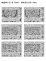
図5は、500Hzの中・低音域の反射音の時間波形と反射音のエネルギー減衰(レベル減衰)のグラフを示す。図5(a)は評価点Aのグラフを示し、図5(b)は評価点Bにおけるグラフを示している。
このように、壁面のみの場合は、鏡面反射となり反射音が拡散されないため、特定の時間に振幅の大きい反射波が現れる。このような反射音は、音響諸室のような閉空間においては、フラッターエコーやロングパスエコーの原因となる。
図6は、500Hzにおける瞬時音圧分布を示すシミュレーション結果である。実際に、鏡面反射を起こしている様子が分かる。
図7は、2000Hzの高音域の反射音の時間波形と反射音のエネルギー減衰(レベル減衰)のグラフを示す。図5との中・低音域と同様に、特定の時間に振幅の大きい反射波が現れている。図7(a)は評価点Aのグラフを示し、図7(b)は評価点Bにおけるグラフを示す。
このように、直接音と、振幅の大きい反射波が現れると、それぞれの音の干渉により音場に悪影響を及ぼす。この効果は、中・低音域に比べ、高音域の方が顕著に現れる。
図8は、2000Hzの瞬時音圧分布を示すシミュレーション結果である。500Hzと同様に、壁面によるレベルの大きな単一の反射音が現出していることが分かる。FIG. 4 is a conceptual diagram showing the positional relationship among various acoustic rooms, sound sources, evaluation points A, and evaluation points B in a plan view.
FIG. 5 shows a graph of the time waveform of the reflected sound in the middle / low range of 500 Hz and the energy attenuation (level attenuation) of the reflected sound. 5A shows a graph of the evaluation point A, and FIG. 5B shows a graph of the evaluation point B.
As described above, in the case of only the wall surface, the reflection sound is not diffused due to specular reflection, and thus a reflected wave having a large amplitude appears at a specific time. Such reflected sound causes flutter echoes and long pass echoes in closed spaces such as acoustic rooms.
FIG. 6 is a simulation result showing the instantaneous sound pressure distribution at 500 Hz. Actually, it can be seen that specular reflection occurs.
FIG. 7 shows a graph of a time waveform of reflected sound in the high frequency range of 2000 Hz and energy attenuation (level attenuation) of the reflected sound. Similar to the middle / low range in FIG. 5, a reflected wave having a large amplitude appears at a specific time. FIG. 7A shows a graph of the evaluation point A, and FIG. 7B shows a graph of the evaluation point B.
As described above, when a direct sound and a reflected wave having a large amplitude appear, the sound field is adversely affected by interference between the sounds. This effect appears more prominently in the high sound range than in the middle / low sound range.
FIG. 8 is a simulation result showing an instantaneous sound pressure distribution at 2000 Hz. As in the case of 500 Hz, it can be seen that a single reflected sound having a large level due to the wall surface appears.
(比較例2)
次に、図9〜図13を参照して、比較例2について説明する。比較例2においては、「サウンド・トラップ」と呼ばれる音響拡散体を用いてシミュレートしている。このサウンド・トラップは、ベニヤの表面にグラスウールを貼り、上から吊して施工する音響拡散体であり、スタジオ等で一般的に用いられている。
ここでは、幅450mm、配列ピッチ300mmで、壁面に対し45度傾けて配置した一般的なサウンド・トラップである斜め反射板をシミュレートしている。(Comparative Example 2)
Next, Comparative Example 2 will be described with reference to FIGS. In Comparative Example 2, simulation is performed using an acoustic diffuser called “sound trap”. This sound trap is an acoustic diffuser that is constructed by attaching glass wool on the surface of a veneer and suspending it from above, and is generally used in studios and the like.
Here, an oblique reflector, which is a general sound trap, having a width of 450 mm and an arrangement pitch of 300 mm and being inclined by 45 degrees with respect to the wall surface is simulated.
図9は、サウンド・トラップである斜め反射板を壁の一面に配置した例を平面図として示した音響諸室の概念図である。
図10は、500Hzの中・低音域の反射音の時間波形と反射音のエネルギー減衰(レベル減衰)のグラフを示す。図10(a)は評価点Aのグラフを示し、図10(b)は評価点Bにおけるグラフを示している。レベル減衰のグラフの矢印は、エネルギー減衰の減衰度(レベル減衰の勾配)を概念的に示したものである。
この従来のサウンド・トラップを用いた例では、反射音の他に拡散音の時間波形と、拡散音のエネルギーによる効果もグラフ上に表されており、比較例1に比べて拡散効果があることが分かる。
しかしながら、評価点Aと評価点Bとで、反射音とレベル減衰が大きく異なっていることが分かる。特に、レベル減衰の勾配のパターンが大きく異なっている。
図11は、500Hzにおける瞬時音圧分布を示すシミュレーション結果である。この図面によると、斜め反射板により反射された波が、塊状になって反射されていることが分かる。図11の19msの図に矢印で示したように、主に2つの方向に塊となって反射されていることが分かる。つまり、特定の方向に強い反射が起こっていることが分かる。
すなわち、上述の壁のみの場合に比べて拡散されてはいるが、この特定の方向に反射された音波が到達することで、受音点により音場が著しく異なる。
このように、聴く場所により音場の差が大きいということは、いわゆる「スイート・スポット」が狭いことへとつながる。
図12は、2000Hzの高音域の反射音の時間波形と反射音のエネルギー減衰(レベル減衰)のグラフを示す。図12(a)は評価点Aのグラフを示し、図12(b)は評価点Bにおけるグラフを示す。グラフの上では、一見、時間波形とレベル減衰は、低音域よりも差が少ないように見える。
図13は、2000Hzの瞬時音圧分布を示すシミュレーション結果である。ここで、上述のグラフでは分かりづらかったが、例えば、図13の楕円形に波線で囲った箇所に、特定の方向への強い反射が起こっており、この反射音が時間の経過とともにあまり減衰しないことが分かる。このように、時間の経過とともに変化しない反射音は、特定の周波数でカラレーションが起こる原因になる。FIG. 9 is a conceptual diagram of acoustic rooms showing a plan view of an example in which an oblique reflector as a sound trap is arranged on one surface of a wall.
FIG. 10 shows a graph of the time waveform of the reflected sound in the middle / low range of 500 Hz and the energy attenuation (level attenuation) of the reflected sound. FIG. 10A shows a graph of the evaluation point A, and FIG. 10B shows a graph of the evaluation point B. The arrows in the level attenuation graph conceptually indicate the energy attenuation attenuation (gradient of level attenuation).
In the example using the conventional sound trap, the time waveform of the diffuse sound and the effect of the energy of the diffuse sound are also shown on the graph in addition to the reflected sound, and there is a diffusion effect compared to the comparative example 1. I understand.
However, it can be seen that the reflected sound and the level attenuation are greatly different between the evaluation point A and the evaluation point B. In particular, the level attenuation gradient patterns are greatly different.
FIG. 11 is a simulation result showing the instantaneous sound pressure distribution at 500 Hz. According to this drawing, it can be seen that the waves reflected by the oblique reflector are reflected in a lump shape. As shown by the arrows in the 19 ms diagram of FIG. 11, it can be seen that the light is reflected as a lump mainly in two directions. That is, it can be seen that strong reflection occurs in a specific direction.
That is, the sound field is remarkably different depending on the sound receiving point when the sound wave reflected in this specific direction arrives although it is diffused as compared with the case of the above-described wall alone.
Thus, a large difference in the sound field depending on the listening location leads to a narrow so-called “sweet spot”.
FIG. 12 shows a graph of the time waveform of the reflected sound in the high frequency range of 2000 Hz and the energy attenuation (level attenuation) of the reflected sound. 12A shows a graph of the evaluation point A, and FIG. 12B shows a graph of the evaluation point B. On the graph, at first glance, the time waveform and level attenuation seem to be less different than the bass.
FIG. 13 is a simulation result showing an instantaneous sound pressure distribution at 2000 Hz. Here, although it was difficult to understand in the above-mentioned graph, for example, strong reflection in a specific direction occurs in a portion surrounded by a wavy line in the ellipse of FIG. 13, and this reflected sound does not attenuate so much with time I understand that. Thus, the reflected sound that does not change with the passage of time causes coloration at a specific frequency.
(比較例3)
次に、図14〜図18を参照して、比較例3について説明する。比較例1では、上述のように、柱状反射体を周期的に設置した状態の例についてシミュレートしている。
この音響諸室において、各列の柱状反射体の直径、各柱状反射体の中心間の間隔は、以下の通りである。
○第1列
直径: 50mm
間隔:100mm
○第2列
直径:100mm
間隔:200mm
○第3列
直径:200mm
間隔:400mm
また、各列間(柱状反射体の中心から)の距離は、以下のように固定している。
○第1列〜第2列の距離: 80mm
○第2列〜第3列の距離: 160mm(Comparative Example 3)
Next, Comparative Example 3 will be described with reference to FIGS. In the comparative example 1, as described above, an example in which the columnar reflectors are periodically installed is simulated.
In this acoustic chamber, the diameter of the columnar reflectors in each row and the distance between the centers of the columnar reflectors are as follows.
○ 1st row Diameter: 50mm
Interval: 100mm
○ Second row Diameter: 100mm
Spacing: 200mm
○ Third row Diameter: 200mm
Spacing: 400mm
The distance between each row (from the center of the columnar reflector) is fixed as follows.
○ Distance from the first row to the second row: 80 mm
○ Distance from the second row to the third row: 160 mm
図14は、周期的に配置された3列の柱状反射体を壁の一面に配置した例を平面図として示した音響諸室の概念図である。
図15は、500Hzの中・低音域における、周期的な円柱を配置した壁面の反射の様子を示す、時間波形と反射音のエネルギー減衰(レベル減衰)のグラフを示す。同様に、図15(a)は評価点Aのグラフを示し、図15(b)は評価点Bにおけるグラフを示している。
このような周期的な柱状反射体の場合は、図15で、レベル減衰の勾配を示している矢印を用いて概念的に示したように、評価点AとBとでレベル減衰のしかたが異なることが分かる。また、図15の楕円形の波線で示したように、500Hzでは、反射音が長く残ることが分かる。また、評価点Aと評価点Bにおいて、反射性状の差が大きいことが分かる。すなわち、聴取場所によって残響感が異なるため、よい音場とはいえない。
図16は、500Hzにおける瞬時音圧分布を示すシミュレーション結果である。上述のサウンドトラップのような塊状の反射音は少なく、反射した音波がよく拡散されてはいるものの、周期的なスジ状のパターンとしてみられる。これは、場所による音場の差が周期的に現れることを示している。
図17は、同様に2000Hzの高音域におけるエネルギー減衰(レベル減衰)のグラフである。図15と同様に、レベル減衰の勾配を示す矢印が、評価点AとBとで異なることが分かる。また、波線の円で示したように、評価点AとBとで反射波の性状が異なることが分かる。
さらに、図15と図17を比較すると、レベル減衰の勾配が500Hzと2000Hzで大きく異なることが分かる。これは、特定の周波数に対して特異な反射性状である「カラレーション」の原因となる。
図18は、2000Hzにおける瞬時音圧分布を示すシミュレーション結果である。斜め反射板に比べて、より音波が拡散しているものの、周期的にスジ状のパターンが現れる。これは、500Hzの場合と同様に、場所による音場の差が周期的に現れることを示している。
このように、柱状反射体を周期性の配置にすると、高音域でも中・低音域でも、レベル減衰のレベルが場所により異なり、カラレーションが起こるため、音響諸室の音場として好ましくない。FIG. 14 is a conceptual diagram of acoustic rooms showing, as a plan view, an example in which three rows of columnar reflectors arranged periodically are arranged on one surface of a wall.
FIG. 15 shows a graph of the time waveform and the energy attenuation (level attenuation) of the reflected sound, showing the state of reflection of the wall surface on which the periodic cylinders are arranged in the middle / low sound range of 500 Hz. Similarly, FIG. 15A shows a graph of the evaluation point A, and FIG. 15B shows a graph of the evaluation point B.
In the case of such a periodic columnar reflector, the level attenuation is different between the evaluation points A and B, as conceptually shown in FIG. 15 using the arrows indicating the gradient of level attenuation. I understand that. Further, as shown by the elliptical wavy line in FIG. 15, it can be seen that the reflected sound remains long at 500 Hz. In addition, it can be seen that the difference in reflectivity between the evaluation points A and B is large. In other words, since the reverberation differs depending on the listening location, it cannot be said to be a good sound field.
FIG. 16 is a simulation result showing an instantaneous sound pressure distribution at 500 Hz. There are few lump-like reflected sounds like the above-mentioned sound trap, and although the reflected sound wave is diffused well, it is seen as a periodic streak-like pattern. This indicates that the difference in the sound field depending on the location appears periodically.
FIG. 17 is also a graph of energy attenuation (level attenuation) in the high frequency range of 2000 Hz. As in FIG. 15, it can be seen that the arrows indicating the gradient of level attenuation differ between the evaluation points A and B. Further, as shown by the wavy circle, it can be seen that the properties of the reflected wave are different between the evaluation points A and B.
Further, comparing FIG. 15 with FIG. 17, it can be seen that the gradient of level attenuation is greatly different between 500 Hz and 2000 Hz. This causes “coloration” which is a reflection characteristic peculiar to a specific frequency.
FIG. 18 is a simulation result showing instantaneous sound pressure distribution at 2000 Hz. Although the sound wave is more diffused than the oblique reflector, a streak-like pattern appears periodically. This indicates that the difference in the sound field depending on the location appears periodically as in the case of 500 Hz.
Thus, if the columnar reflectors are arranged in a periodic manner, the level attenuation level varies depending on the location in both the high sound range and the middle / low sound range, and coloration occurs.
(実施例1)
最後に、図19〜図23を参照して、実施例1について説明する。
実施例1では、3列の各列毎にランダムに柱状反射体を配置した、本発明の実施の形態に係る音場調整方法での直径と配置条件とでの配置例についてシミュレートしている。Example 1
Finally, Example 1 will be described with reference to FIGS.
Example 1 simulates an arrangement example with a diameter and an arrangement condition in the sound field adjustment method according to the embodiment of the present invention in which columnar reflectors are arranged randomly for each of three columns. .
図19は、ランダムに配置された3列の柱状反射体を壁の一面に配置した例を平面図として示した音響諸室の概念図である。
この音響諸室においては、上述のように直径と配置条件を算出し、3列(段)の構成とした。各列の柱状反射体の直径、各柱状反射体の中心間の間隔、ターゲット周波数(帯域)は以下の通りである。
○第1列
・直径: 32mm
・間隔: 72〜180mm
・ターゲット周波数: 1000Hz以上
○第2列
・直径: 45mm
・間隔: 55〜133mm
・ターゲット周波数: 約630Hz以上
○第3列
・直径: 60mm
・間隔: 39〜115mm
・ターゲット周波数:約500Hz以上
また、各列間(柱状反射体の中心から)の距離は、以下のように固定している。
○第1列〜第2列の距離: 45mm
○第2列〜第3列の距離: 65mmFIG. 19 is a conceptual diagram of acoustic rooms showing a plan view of an example in which three rows of columnar reflectors arranged at random are arranged on one surface of a wall.
In the acoustic chambers, the diameter and the arrangement conditions were calculated as described above, and the configuration was three rows (stages). The diameter of the columnar reflectors in each row, the distance between the centers of the columnar reflectors, and the target frequency (band) are as follows.
○ 1st row ・ Diameter: 32mm
・ Interval: 72-180mm
・ Target frequency: 1000Hz or more ○ Second row ・ Diameter: 45mm
・ Interval: 55-133mm
・ Target frequency: about 630Hz or more ○ 3rd row ・ Diameter: 60mm
・ Interval: 39-115mm
・ Target frequency: about 500Hz or more
The distance between each row (from the center of the columnar reflector) is fixed as follows.
○ Distance from the first row to the second row: 45 mm
○ Distance from the second row to the third row: 65 mm
図20は、500Hzの中・低音域における、ランダムに円柱を配置した壁面の反射の様子を示す、時間波形と反射音のエネルギー減衰(レベル減衰)のグラフを示す。同様に、図20(a)は評価点Aのグラフを示し、図20(b)は評価点Bにおけるグラフを示している。
壁面にランダムに円柱を配置した壁面では、壁のみの場合(比較例1)と、斜め反射板(比較例2)、周期的な円柱(比較例3)に比べて、反射音がよく拡散され、癖のない自然な響きをもたらしていることが分かる。また、受音点AとBとで、レベル減衰の勾配の差があまりなく、減衰時間の勾配と減衰するまでの時間の差が少ないことが分かる。すなわち、場所による反射性状の違いが小さく、広い範囲で同質で良質な音場を得ることが可能であることが分かる。
図21は、500Hzにおける瞬時音圧分布を示すシミュレーション結果である。ここでも、上述の各比較例に比べると、波線の楕円で示したように、時間と供に強い音波が観測される場所が変化することが分かる。これにより、反射音が広範囲に細かく拡散していることが分かる。つまり、受音点での差異が少なく、均一な拡散が得られることが分かる。
図22は、同様に、2000Hzの場合のエネルギー減衰(レベル減衰)のグラフである。こちらでも、比較例1〜3に比べて、受音点AとBとで、レベル減衰の勾配の差があまりなく、減衰するまでの時間に差が少なく、広い範囲で同質かつ良質な音場が実現されていることが分かる。すなわち、癖がない自然な響きになっている。
図23は、2000Hzにおける瞬時音圧分布を示すシミュレーション結果である。ここでも、全体的に綺麗に反射音がよく拡散され、図18の周期的な円柱のようにスジ状の周期的なパターンが少なく、場所により時間的に音波の強い場所が変化してゆくことが分かる。つまり、均一な音場が得られるという特徴がある。
このように、本発明の実施の形態に係る音場調整方法を用いると、音響的に非常に優れた音響諸室を得ることができる。FIG. 20 shows a graph of the time waveform and the energy attenuation (level attenuation) of the reflected sound, showing the state of reflection on the wall surface in which the cylinders are randomly arranged in the middle / low sound range of 500 Hz. Similarly, FIG. 20A shows a graph of the evaluation point A, and FIG. 20B shows a graph of the evaluation point B.
On the wall surface where cylinders are randomly arranged on the wall surface, the reflected sound is diffused better than the case of only the wall (Comparative Example 1), the oblique reflector (Comparative Example 2), and the periodic cylinder (Comparative Example 3). , You can see that it has a natural sound without a habit. It can also be seen that there is not much difference in the level attenuation gradient between the sound receiving points A and B, and there is little difference in the attenuation time gradient and time until attenuation. That is, it can be seen that there is little difference in reflective properties depending on the location, and it is possible to obtain a high quality sound field of the same quality over a wide range.
FIG. 21 is a simulation result showing instantaneous sound pressure distribution at 500 Hz. Here again, as compared with the comparative examples described above, it can be seen that the location where strong sound waves are observed changes with time, as indicated by the ellipses of the wavy lines. Thus, it can be seen that the reflected sound is finely diffused over a wide range. That is, it can be seen that there is little difference in the sound receiving points and uniform diffusion can be obtained.
Similarly, FIG. 22 is a graph of energy attenuation (level attenuation) in the case of 2000 Hz. Again, compared to Comparative Examples 1 to 3, there is not much difference in the level attenuation gradient between the sound receiving points A and B, there is little difference in time to attenuation, and the sound field has the same and good quality over a wide range. It can be seen that is realized. In other words, it has a natural sound with no habit.
FIG. 23 is a simulation result showing instantaneous sound pressure distribution at 2000 Hz. Here too, the reflected sound is well diffused as a whole, there are few streak-like periodic patterns like the periodic cylinder in FIG. 18, and the place where the sound wave is strong changes with time. I understand. That is, there is a feature that a uniform sound field can be obtained.
As described above, when the sound field adjustment method according to the embodiment of the present invention is used, acoustic rooms that are acoustically excellent can be obtained.
〔音波の拡散性の比較〕
次に、同様のシミュレーションにより、側壁の拡散性の比較を行った。
このシミュレーションでは、音波が側壁に到達した際の拡散波の密度を計算して図示化することで、均一な音場ができているかを知ることができる。[Comparison of sound diffusivity]
Next, the side wall diffusivity was compared by the same simulation.
In this simulation, it is possible to know whether or not a uniform sound field is created by calculating and illustrating the density of the diffusion wave when the sound wave reaches the side wall.
(比較例4)
図24を参照して、上述のサウンド・トラップを使用してシミュレートした場合について示す。
壁面600は、奥行きが100mmのコンクリートの壁を示す。
音波面610は、単一の音源から出力された音波のエネルギーを図示したものである。
拡散波面620は、音波面610の音波が反射・拡散した際の音波のエネルギーを図示したものである。
サウンド・トラップ群630は、サウンドトラップをシミュレートしたものである。ここでは、サウンド・トラップ群630は、上述の比較例2と同様に、幅450mm、配列ピッチ300mmで、壁面600に対し45度傾けて配置したものを用いた。(Comparative Example 4)
Referring to FIG. 24, the simulation is performed using the sound trap described above.
A
The
The
The
シミュレーションの結果、拡散波面620を見ると、ほぼ単一の方向に、あまり拡散されない反射波が放射されていて、この波面の到達する場所も狭いことが分かる。
このような状態は、音場環境が良い場所(「スイートスポット」)が狭いことを示すため、良くない音場であるといえる。As a result of the simulation, when the
Such a state indicates that the place where the sound field environment is good (“sweet spot”) is narrow, so it can be said that the sound field is not good.
(実施例2)
図25を参照して、本発明の実施の形態に係る音場調整方法にて直径と配置条件とを算出した、柱状反射体を用いてシミュレートした場合について示す。
壁面700は、比較例4と同じ奥行きが100mmのコンクリートの壁を示す。
音波面710は、音波面610と同様に、単一の音源から出力された音波のエネルギーを示す。
拡散波面720は、音波面710の音波が反射・拡散した際の音波のエネルギーを示す。
柱状構造体群730の各列の柱状反射体の直径、各柱状反射体の中心間の間隔、ターゲット周波数(帯域)は以下の通りである。
○第1列
・直径32mm
・間隔72〜180mm
・ターゲット周波数: 1000Hz以上
○第2列
・直径45mm
・間隔55〜133mm
・ターゲット周波数: 約630Hz以上
○第3列
・直径60mm
・間隔39〜115mm
・ターゲット周波数:約500Hz以上
○第4列
・直径115mm、165mm、又は216mm
・間隔60〜210mmの間でランダム
・ターゲット周波数: 500Hz以下
また、各列間(柱状反射体の中心から)の距離は、以下のように固定している。
○第1列〜第2列の距離: 45mm
○第2列〜第3列の距離: 65mm
○第3列〜第4列の距離: 約125〜204mm(ランダムなので概略の寸法)
第4列については、115mmの第4列、165mmの第5列、216mmの第6列と列を分けて配置することもできるが、施工スペースと利便性を考慮して、3種類の円柱を列、行とも入り乱れたランダムに配置することとした。
なお、低音は、指向性が低いために、このようなランダム配置を行ってもそれほど差がでないために有効である。(Example 2)
With reference to FIG. 25, a case where a diameter and an arrangement condition are calculated by a sound field adjusting method according to an embodiment of the present invention and simulated using a columnar reflector will be described.
The
Similar to the
The
The diameter of the columnar reflectors in each column of the
○ 1st row ・ Diameter 32mm
・ Distance 72-180mm
・ Target frequency: 1000Hz or more
○ 2nd row ・ Diameter 45mm
・ Spacing 55-133mm
・ Target frequency: About 630Hz or more
○ 3rd row ・ Diameter 60mm
・ Spacing 39-115mm
・ Target frequency: about 500Hz or more
○ Fourth row-Diameter 115mm, 165mm, or 216mm
-Random between 60-210mm spacing-Target frequency: 500Hz or less
The distance between each row (from the center of the columnar reflector) is fixed as follows.
○ Distance from the first row to the second row: 45 mm
○ Distance from the second row to the third row: 65 mm
○ Distance from the third row to the fourth row: about 125 to 204 mm (rough dimensions because it is random)
Regarding the fourth row, the fourth row of 115 mm, the fifth row of 165 mm, the sixth row of 216 mm and the sixth row can be arranged separately, but considering the construction space and convenience, three types of columns are used. Both columns and rows were randomly placed in random order.
Note that the bass is effective because the directivity is low and there is not much difference even if such a random arrangement is performed.
シミュレーションの結果、拡散波面720は、拡散波面620よりも、非常に均一に放射されていることが分かる。
また、反射波の波面が揃っておらず、均一に拡散が行われていることが分かる。
さらに、拡散波面720は、拡散波面620と異なり、広い方向に拡散された音波のエネルギーが分布されていることが分かる。
これらの結果から鑑みると、従来の「サウンド・トラップ」を用いた音響拡散体よりも、広いスイートスポットで均一な音場を実現することが可能である。
よって、本発明の実施の形態に係る音場調整方法では、より良い音場を提供できることが分かる。As a result of the simulation, it can be seen that the
It can also be seen that the wave fronts of the reflected waves are not uniform and the diffusion is performed uniformly.
Further, unlike the
In view of these results, it is possible to realize a uniform sound field with a wider sweet spot than an acoustic diffuser using a conventional “sound trap”.
Therefore, it can be seen that the sound field adjustment method according to the embodiment of the present invention can provide a better sound field.
〔反射体構造物の音響材料パラメータの比較〕
本発明の実施の形態に係る反射体構造物について、周波数帯域毎に複素反射係数(Complex Reflection Coefficient)より音圧反射率(位相)変化を測定し、音響材料パラメータを調べた。この測定では、剛壁800に向かって音を発生させて、丸棒810の有無及び太さの違い、吸音材820の有無による音圧反射率(位相)の変化を測定した。そして、周波数帯域毎に位相の変化や時間遅れが生じるかどうか確認した。[Comparison of acoustic material parameters of reflector structure]
With respect to the reflector structure according to the embodiment of the present invention, the sound pressure reflectivity (phase) change was measured from the complex reflection coefficient (Complex Reflection Coefficient) for each frequency band, and the acoustic material parameters were examined. In this measurement, sound was generated toward the
図26(a)を参照して、比較例5、実施例3、実施例4、実施例5における音響材料パラメータの測定の概念を示す。音源からの音の入射方向を矢印で示す。
比較例5、実施例3、実施例4、実施例5では吸音材820を配置しなかった。
反射体構造物は、反射面が曲面である丸棒810を使用した。
比較例5では丸棒810を配置しなかった。また、図26(a)に示すように、実施例3では1本のφ114mmの丸棒811を配置し、実施例4では1本のφ164mmの丸棒812、実施例5では1本のφ216mmの丸棒813を配置した。丸棒810は、剛壁800から400mmの位置に音源からみた丸棒810の先端部がくるように設置した。
以下で、比較例5、実施例3、実施例4、実施例5の順で各音響材料パラメータの測定結果についてより詳しく説明する。With reference to Fig.26 (a), the concept of the measurement of the acoustic material parameter in the comparative example 5, Example 3, Example 4, and Example 5 is shown. The direction of incident sound from the sound source is indicated by arrows.
In Comparative Example 5, Example 3, Example 4, and Example 5, the
As the reflector structure, a
In Comparative Example 5, the
Below, the measurement result of each acoustic material parameter is demonstrated in detail in order of the comparative example 5, Example 3, Example 4, and Example 5. FIG.
(比較例5)
図26(b)を参照して、反射体構造物が存在しない場合の音圧反射率(位相)の測定結果について示す。
この場合、音圧反射数(位相)は、全ての周波数帯において、ほぼ0付近の値が測定された。すなわち、全ての周波数帯域で、位相の変化が生じておらず時間遅れも生じていないことを示す。(Comparative Example 5)
With reference to FIG.26 (b), it shows about the measurement result of the sound pressure reflectance (phase) in case a reflector structure does not exist.
In this case, the sound pressure reflection number (phase) was measured at a value near 0 in all frequency bands. That is, it shows that no phase change occurs and no time delay occurs in all frequency bands.
(実施例3)
次に、図26(b)を参照して、反射体構造物が存在する場合の音圧反射率(位相)の測定結果について示す。
反射体構造物として1本のφ114mmの丸棒811を用いた場合、音圧反射率(位相)は、100Hz付近から位相がマイナス側に変化し時間遅れが生じており、266Hz付近で位相のマイナス側への変化がピークとなった。また、500Hz以上の周波数帯域では、プラス側に変化をしていた。(Example 3)
Next, with reference to FIG.26 (b), it shows about the measurement result of the sound pressure reflectance (phase) in case a reflector structure exists.
When one
(実施例4)
また、図26(b)を参照して、反射体構造物が存在する場合の音圧反射率(位相)の測定結果について示す。
反射体構造物として1本のφ164mmの丸棒812を用いた場合、音圧反射率(位相)は、100Hz付近から位相がマイナス側に変化し時間遅れが生じており、247Hz付近で位相のマイナス側への変化がピークとなった。また、500Hz以上の周波数帯域では、プラス側に変化をしていた。
実施例3と比較すると、0からの値の変化がより大きくなっていると共に、マイナス側へのピークの位置が低周波数側にずれていた。Example 4
In addition, with reference to FIG. 26B, the measurement result of the sound pressure reflectance (phase) when the reflector structure is present will be described.
When one φ164 mm round bar 812 is used as the reflector structure, the sound pressure reflectance (phase) changes from the vicinity of 100 Hz to the negative side, causing a time delay, and the phase is negative near 247 Hz. The change to the side peaked. Moreover, in the frequency band of 500 Hz or more, it changed to the plus side.
Compared with Example 3, the change from 0 was larger and the peak position on the minus side was shifted to the low frequency side.
(実施例5)
また、図26(b)を参照して、反射体構造物が存在する場合の音圧反射率(位相)の測定結果について示す。
反射体構造物として1本のφ216mmの丸棒813を用いた場合、音圧反射率(位相)は、100Hz付近から位相がマイナス側に変化し時間遅れが生じており、215Hz付近で位相のマイナス側への変化がピークとなった。また、500Hz以上の周波数帯域では、プラス側に変化をしていた。
実施例3及び実施例4と比較すると、0からの値の変化がより大きくなっていると共に、さらにマイナス側へのピークの位置が低周波数側にずれていた。(Example 5)
In addition, with reference to FIG. 26B, the measurement result of the sound pressure reflectance (phase) when the reflector structure is present will be described.
When one Φ216 mm
Compared with Example 3 and Example 4, the change from 0 was larger, and the peak position toward the minus side was further shifted to the low frequency side.
比較例5、実施例3、実施例4、実施例5より、丸棒810の直径の大きさに依存して、対象となる周波数帯域における音波が周り込むため時間遅れが生じる。すなわち、丸棒810の占める容積の分だけ、背後スペースが減っているのと同等の結果になる。また、対象周波数帯よりも高域では時間進みが生じる。これは丸棒810の表面で反射しているからである。さらに、対象周波数帯よりも低域では、音圧反射率(位相)がほぼ0付近の値が測定されたため、丸棒810は無視されて素通りする。
このように、反射体構造物の直径の寸法や大きさに応じて、音圧反射率(位相)が特徴的に変化し、音響周波数に対応する。そして、より直径が太い(大きい)反射体構造物を用いることによって低周波数帯域の時間遅れを調節することが可能となり、より直径が細い(小さい)反射体構造物を用いることによって高周波数帯域の時間遅れを調節することが可能となる。
したがって、反射体構造物の直径の太さや大きさを調整することによって、多様な反射を生み出して意図的に反射時間を調節することが可能となり、さらに入射角度により多様な効果が生じる。From Comparative Example 5, Example 3, Example 4, and Example 5, depending on the size of the diameter of the
Thus, the sound pressure reflectance (phase) changes characteristically according to the size and size of the diameter of the reflector structure, and corresponds to the acoustic frequency. Then, it becomes possible to adjust the time delay of the low frequency band by using a reflector structure having a larger diameter (larger), and by using a reflector structure having a smaller diameter (smaller), It becomes possible to adjust the time delay.
Therefore, by adjusting the thickness and size of the diameter of the reflector structure, it is possible to intentionally adjust the reflection time by generating various reflections, and various effects are produced depending on the incident angle.
図27(a)を参照して、比較例6、実施例6、実施例7における音響材料パラメータの測定の概念を示す。音源からの音の入射方向を矢印で示す。
吸音材820は、GW24k50tを使用した。
反射体構造物は、反射面が曲面である丸棒810を使用した。
比較例6では丸棒810を配置しなかった。また、図27(a)に示すように、実施例6ではφ216mmの丸棒813を1本のみ配置し、実施例7ではφ114mmの丸棒811及びφ216mmの丸棒813の計2本配置した。図27(a)の右側に200mm及び400mmの寸法を示す。
以下で、比較例6、実施例6、実施例7の順で各音響材料パラメータの測定結果についてより詳しく説明する。With reference to Fig.27 (a), the concept of the measurement of the acoustic material parameter in the comparative example 6, Example 6, and Example 7 is shown. The direction of incident sound from the sound source is indicated by arrows.
As the
As the reflector structure, a
In Comparative Example 6, the
Hereinafter, the measurement results of each acoustic material parameter will be described in more detail in the order of Comparative Example 6, Example 6, and Example 7.
(比較例6)
図27(b)を参照して、吸音材820(GW24k50t)が存在し、反射体構造物が存在しない場合の音圧反射率(位相)の測定結果について示す。
この場合、音圧反射数(位相)は、全ての周波数帯においてほぼ0付近の値が測定された。すなわち、全ての周波数帯域で、位相の変化が生じておらず時間遅れも生じていないことを示し、位相の変化が吸音材820に依存しないことが示された。(Comparative Example 6)
With reference to FIG. 27 (b), the measurement result of the sound pressure reflectance (phase) when the sound absorbing material 820 (GW 24k50t) is present and the reflector structure is not present will be described.
In this case, the sound pressure reflection number (phase) was measured at a value near 0 in all frequency bands. That is, it was shown that no phase change occurred and no time delay occurred in all frequency bands, and it was shown that the phase change does not depend on the
(実施例6)
また、図27(b)を参照して、吸音材820(GW24k50t)が存在し、且つ反射体構造物が存在する場合の音圧反射率(位相)の測定結果について示す。
反射体構造物としてφ216mmの丸棒813を1本のみ用いた場合、音圧反射率(位相)は、150Hz付近から位相がマイナス側に変化し時間遅れが生じており、276Hz付近で位相のマイナス側への変化がピークとなった。(Example 6)
In addition, with reference to FIG. 27 (b), the measurement result of the sound pressure reflectance (phase) when the sound absorbing material 820 (GW 24k50t) is present and the reflector structure is present is shown.
When only one φ216 mm
(実施例7)
また、図27(b)を参照して、吸音材820(GW24k50t)が存在し、且つ反射体構造物が存在する場合の音圧反射率(位相)の測定結果について示す。
反射体構造物としてφ114mmの丸棒811及びφ216mmの丸棒813の計2本用いた場合、音圧反射率(位相)は、150Hz付近から位相がマイナス側に変化し時間遅れが生じており、260Hz付近で位相のマイナス側への変化がピークとなった。比較例6及び実施例6と比較すると、位相が0から変化している周波数帯域がより広範に渡っていた。このように、音源から遠ざかるに方向に直径が大きくなるように丸棒810を複数配置することにより、単独で配置した場合の反射様式と比較して、配置された丸棒810の間で多層反射というさらなる相乗効果も生じている。(Example 7)
In addition, with reference to FIG. 27 (b), the measurement result of the sound pressure reflectance (phase) when the sound absorbing material 820 (GW 24k50t) is present and the reflector structure is present is shown.
When a total of two φ114 mm round
なお、音源に対して、直径が太い丸棒810が、直径が細い丸棒810の前に存在すると、音圧反射率は直径が太い丸棒810によって支配される。しかし、音源に対して、直径が細い丸棒810が、直径が太い丸棒810の前に存在すると、各々の丸棒810単独の拡散効果のみならず、両者の丸棒810の間で生じる多層反射等による相乗効果でさらなる乱反射が生じる。
これにより、音の進入方向に対し、直径がより細い(小さい)反射体構造物から直径がより太い(大きい)反射体構造物へと入射する場合、音がスムーズに反射体構造物周辺で作用するので、インピーダンスが低い方から高い方へとスムーズに変化するという効果が得られる。If a
As a result, when sound enters from a thinner (smaller) reflector structure to a thicker (larger) reflector structure with respect to the direction of sound entry, the sound acts smoothly around the reflector structure. Therefore, the effect of smoothly changing from a low impedance to a high impedance can be obtained.
図28(a)を参照して、実施例8及び実施例9における音響材料パラメータの測定の概念を示す。音源からの音の入射方向を矢印で示す。
吸音材820は、GW24k50tを使用した。
反射体構造物は、反射面が曲面である丸棒810を使用した。
実施例8ではφ216mmの丸棒813及び小型丸棒群814を配置し、実施例9ではφ114mmの丸棒811、φ216mmの丸棒813、及び小型丸棒群814を配置した。小型丸棒群814とは、2本のφ60mm、3本のφ45mm、及び4本のφ30mmの丸棒を図28(a)に示すように配置したものである。図28(a)の右側に200mm及び400mmの寸法を示す。
以下で、実施例8、実施例9の順で各音響材料パラメータの測定結果についてより詳しく説明する。With reference to Fig.28 (a), the concept of the measurement of the acoustic material parameter in Example 8 and Example 9 is shown. The direction of incident sound from the sound source is indicated by arrows.
As the
As the reflector structure, a
In Example 8, a φ216 mm
Hereinafter, the measurement results of the acoustic material parameters will be described in more detail in the order of Example 8 and Example 9.
(実施例8)
図28(b)を参照して、吸音材820(GW24k50t)が存在し、且つ反射体構造物が存在する場合の音圧反射率(位相)の測定結果について示す。
反射体構造物としてφ216mmの丸棒813及び小型丸棒群814を用いた場合、音圧反射率(位相)は、100Hz付近から位相がマイナス側に変化し反射時間の遅れが生じており、342Hz付近で位相のマイナス側への変化がピークとなった。実施例6及び実施例7と比較すると、位相が0から変化している周波数帯域がより広範に渡っており、その値の変化もより大きくなっていた。(Example 8)
With reference to FIG. 28 (b), the measurement result of the sound pressure reflectance (phase) when the sound absorbing material 820 (GW 24k50t) is present and the reflector structure is present will be described.
When a φ216 mm
(実施例9)
図28(b)を参照して、吸音材820(GW24k50t)が存在し、且つ反射体構造物が存在する場合の音圧反射率(位相)の測定結果について示す。
反射体構造物としてφ114mmの丸棒811、φ216mmの丸棒813及び小型丸棒群814を用いた場合、音圧反射率(位相)は、100Hz付近から位相がマイナス側に変化し時間遅れが生じており、371Hz付近で位相のマイナス側への変化がピークとなった。実施例6及び実施例7と比較すると、位相が0から変化している周波数帯域がより広範に渡っており、その値の変化もより大きくなっていた。また、実施例8と比較しても、0からの値の変化がより大きくなっていた。Example 9
With reference to FIG. 28 (b), the measurement result of the sound pressure reflectance (phase) when the sound absorbing material 820 (GW 24k50t) is present and the reflector structure is present will be described.
When a φ114 mm
したがって、音源から近い位置の丸棒810よりも音源から遠い位置の丸棒810の直径又は太さが大きくなるように配置された場合には、周波数帯域が異なる音波の反射方向及び/又は反射時間遅れ又は反射音の位相がランダムになる複数の反射面をより多く形成することが示される。さらに、より多くの丸棒810が組み合わされば組み合わさるほど、多様な拡散音を生じるという効果が生じる。
Therefore, when the
また、上記比較例5〜6及び実施例3〜9では、垂直入射管内における柱状反射体の音響インピーダンスのパラメーターの実測値を測定しているともいえる(図26(b)、図27(b)、図27(b)参照)。
これによると、φ216mmの丸棒813(太管)の複素反射率の位相部分は、固有の受け持ち周波数帯域において固有の位相ずれを持つが、太管の前(音源側)にφ114mmの丸棒811(中管)を適度な間隔をあけて設置しても、太管の特性と中管の特性が加算されたように測定される。
さらに、それらの前部に小型丸棒群814(小管群)を設置しても、太管及び中管の基本特性は変わっていないことが分かり、太管、中管、小管群との間にカラレーション等の特異な現象が起こっていないことが分かる。
本発明の実施の形態に係る柱状反射体は、直径の異なる柱状反射体を組み合わせて使用しているので、周波数により固有のインピーダンスを持つが、この例によってもインピーダンスのマッチングを良好に行えることが分かる。In Comparative Examples 5-6 and Examples 3-9, it can be said that the measured values of the acoustic impedance parameters of the columnar reflector in the vertical incidence tube are measured (FIGS. 26B and 27B). FIG. 27 (b)).
According to this, the phase portion of the complex reflectance of the φ216 mm round bar 813 (thick tube) has an inherent phase shift in the inherent frequency band, but the φ114 mm
Furthermore, even if a small round bar group 814 (small pipe group) is installed at the front part thereof, it can be seen that the basic characteristics of the large pipe and the middle pipe have not changed. It can be seen that unique phenomena such as coloration do not occur.
Since the columnar reflector according to the embodiment of the present invention uses a combination of columnar reflectors having different diameters, the columnar reflector has a specific impedance depending on the frequency. I understand.
〔反射体構造物の吸音率の比較〕
本発明の実施の形態に係る反射体構造物について、周波数帯域毎に残響室法吸音率の測定を行い、吸音率の変化を調べた。この測定では、丸棒810並びに吸音材821及び822を通過させた場合の吸音率の変化を測定した。そして、周波数帯域毎に吸音率の変化が生じるかどうか確認した。
なお、本発明の実施の形態に係る反射体構造物を使用せずに、吸音材821及び822単独で使用した場合には、高周波数帯域で特に吸音過多になる。[Comparison of sound absorption coefficient of reflector structure]
About the reflector structure which concerns on embodiment of this invention, the reverberation room method sound absorption rate was measured for every frequency band, and the change of the sound absorption rate was investigated. In this measurement, the change in the sound absorption coefficient when passing through the
When the
図29(a)を参照して、実施例10、実施例11、実施例12、実施例13における反射体構造物の吸音率の測定の概念を示す。音源からの音の入射方向を矢印で示す。
吸音材821及び822は、GW24k50tもしくはジャージクロスを使用した。吸音材821は、細丸棒群815及び太丸棒群816の間に配置した。また、吸音材822は、太丸棒群816の音源から遠い側に配置した。
反射体構造物は、反射面が曲面である丸棒810を使用した。具体的には、図29(a)に示す細丸棒群815及び太丸棒群816を使用し、各丸棒が音源から遠ざかるにつれて直径が大きくなるように配置した。
実施例10では吸音材821及び吸音材822を配置せず、実施例11では吸音材822(GW24k50t)のみ配置し、実施例12では吸音材821(ジャージクロス)及び822(GW24k50t)を配置し、実施例13では吸音材821(GW24k50t)及び822(GW24k50t)を配置した。
以下で、実施例10、実施例11、実施例12、実施例13の順で吸音率の変化の測定結果についてより詳しく説明する。With reference to Fig.29 (a), the concept of the measurement of the sound absorption rate of the reflector structure in Example 10, Example 11, Example 12, and Example 13 is shown. The direction of incident sound from the sound source is indicated by arrows.
As the
As the reflector structure, a
In Example 10, the
Hereinafter, measurement results of changes in sound absorption coefficient will be described in more detail in the order of Example 10, Example 11, Example 12, and Example 13.
(実施例10)
図29(b)を参照して、吸音材821及び822が存在しない場合に、反射体構造物が存在する場合の周波数毎の吸音率の測定結果について示す。
この場合、吸音率は、およそ0.28(周波数125Hz)〜0.13(周波数4000Hz)の範囲内で低周波数帯域から高周波数帯域にかけてほぼ同様の値が測定された。(Example 10)
With reference to FIG. 29 (b), the measurement result of the sound absorption rate for each frequency when the
In this case, almost the same value was measured for the sound absorption coefficient from the low frequency band to the high frequency band within a range of about 0.28 (
(実施例11)
図29(b)を参照して、吸音材822(GW24k50t)が存在し、且つ反射体構造物が存在する場合の周波数毎の吸音率の測定結果について示す。
この場合、吸音率は、およそ0.53(周波数125Hz)〜0.20(周波数4000Hz)の範囲内で低周波数帯域から高周波数帯域にかけてほぼ同様の値が測定された。実施例10と比較すると、吸音率は全周波数帯域において上昇していた。(Example 11)
Referring to FIG. 29 (b), the measurement result of the sound absorption coefficient for each frequency when the sound absorbing material 822 (GW 24k50t) is present and the reflector structure is present is shown.
In this case, almost the same value was measured for the sound absorption coefficient from the low frequency band to the high frequency band within a range of about 0.53 (
(実施例12)
図29(b)を参照して、吸音材821(ジャージクロス)及び吸音材822(GW24k50t)が存在し、且つ反射体構造物が存在する場合の周波数毎の吸音率の測定結果について示す。
この場合、吸音率は、およそ0.53(周波数125Hz)〜0.20(周波数4000Hz)の範囲内で低周波数帯域から高周波数帯域にかけてほぼ同様の値が測定された。実施例10及び実施例11と比較すると、吸音率は全周波数帯域において上昇していた。(Example 12)
With reference to FIG. 29 (b), the measurement results of the sound absorption coefficient for each frequency when the sound absorbing material 821 (jersey cloth) and the sound absorbing material 822 (GW 24k50t) are present and the reflector structure is present will be described.
In this case, almost the same value was measured for the sound absorption coefficient from the low frequency band to the high frequency band within a range of about 0.53 (
(実施例13)
図29(b)を参照して、吸音材821(GW24k50t)及び吸音材822(GW24k50t)が存在し、且つ反射体構造物が存在する場合の周波数毎の吸音率の測定結果について示す。
この場合、吸音率は、およそ0.67(周波数125Hz)〜0.38(周波数4000Hz)の範囲内で低周波数帯域から高周波数帯域にかけてほぼ同様の値が測定された。実施例10、実施例11、実施例12と比較すると、吸音率は全周波数帯域において上昇していた。(Example 13)
With reference to FIG. 29 (b), the measurement result of the sound absorption coefficient for each frequency when the sound absorbing material 821 (GW 24k50t) and the sound absorbing material 822 (GW 24k50t) are present and the reflector structure is present will be described.
In this case, almost the same value was measured for the sound absorption coefficient from the low frequency band to the high frequency band within a range of about 0.67 (
一般に吸音材のみでは、低周波数帯域よりも高周波数帯域の吸音力が大きくなる。しかし、実施例10、実施例11、実施例12、実施例13のように、本発明の反射体構造物と吸音材を使用することによって、全周波数帯域に対して、一律に影響を与えるような吸音特性が実現される。特に、中間や背後スペース等に吸音材を入れることによって、低音域と高音域の吸音の特性を調整し、全周波数帯域において吸音率を減少させるような任意の吸音特性を実現できる。このような本発明の反射体構造物の吸音効果は、類例をみないものであり、当業者に容易に想到できない。また、本発明の反射体構造物と任意の吸収材との組み合わせによって、各周波数帯域に対応した可能な多種多様な吸音率を持つ音響特性を容易に実現できる。
更に反射体内部の空間を利用し、ヘルムホルツ吸音機構や微小孔板吸音機構等による特定の周波数を対象とした吸音力を備えることができ、とりわけ室の低域の定在波対策に効果的である。In general, only a sound absorbing material has a higher sound absorbing power in a high frequency band than in a low frequency band. However, as in Example 10, Example 11, Example 12, and Example 13, by using the reflector structure and the sound absorbing material of the present invention, the entire frequency band is uniformly affected. Sound absorption characteristics are realized. In particular, by inserting a sound absorbing material in the middle or behind the space, it is possible to adjust the sound absorption characteristics in the low and high sound ranges and realize any sound absorption characteristic that reduces the sound absorption rate in the entire frequency band. Such a sound absorbing effect of the reflector structure of the present invention is unparalleled and cannot be easily conceived by those skilled in the art. In addition, by combining the reflector structure of the present invention and an arbitrary absorber, it is possible to easily realize acoustic characteristics having a wide variety of possible sound absorption rates corresponding to each frequency band.
In addition, the space inside the reflector can be used to provide sound absorption for specific frequencies by means of the Helmholtz sound absorption mechanism or the micro-hole plate sound absorption mechanism, which is particularly effective as a countermeasure against standing waves in the low frequencies of the room. is there.
〔反射体構造物の透過損失の比較〕
本発明の実施の形態に係る反射体構造物について、周波数帯域毎に反射体構造物の透過損失を測定し、透過損失の変化を調べた。この測定では、反射体構造物を通り抜ける時の音の減衰量を測定して確認した。ここで透過損失が大きい値であると音が通り抜けにくいことを示し、音源側に音を反射していることを表す。また、透過損失が小さい値であると受音側に音が通り抜け易いことを示し、音源側に少ししか反射しないことを表す。[Comparison of transmission loss of reflector structure]
About the reflector structure which concerns on embodiment of this invention, the transmission loss of the reflector structure was measured for every frequency band, and the change of the transmission loss was investigated. In this measurement, the attenuation of sound when passing through the reflector structure was measured and confirmed. Here, if the transmission loss is a large value, it indicates that the sound is difficult to pass through and indicates that the sound is reflected to the sound source side. Further, if the transmission loss is a small value, it indicates that the sound is likely to pass through to the sound receiving side, and represents that the sound is reflected slightly to the sound source side.
図30(a)を参照して、実施例14における反射体構造物の透過損失の測定の概念を示す。
反射体構造物は、反射面が曲面である丸棒810を使用した。図30(a)の左側は音源側からみた反射体構造物を示し、右側は受音側からみた反射体構造物を示す。このように複数の丸棒810は、音源から音が通過する方向につれて直径の細い丸棒から太い丸棒になるように配置した。
以下の実施例14で反射体構造物の透過損失の測定結果についてより詳しく説明する。With reference to Fig.30 (a), the concept of the measurement of the transmission loss of the reflector structure in Example 14 is shown.
As the reflector structure, a
The measurement result of the transmission loss of the reflector structure will be described in more detail in Example 14 below.
(実施例14)
図30(b)を参照して、反射体構造物が存在する場合の周波数帯域毎の透過損失の測定結果について示す。
この場合、透過損失は、高周波数帯域になるについて透過損失の値が上昇していた。例えば、透過損失は、約3dB(周波数400Hz)から約6dB(周波数1250Hz)というように上昇していた。なお、透過損失3dBでエネルギーが1/2になり、透過損失6dBでエネルギー1/4になる。ここで、透過損失=10log(1/開口率)とみなすと、開口率1/2で透過損失が3dB、開口率1/4で透過損失が6dBと計算される。(Example 14)
With reference to FIG.30 (b), it shows about the measurement result of the transmission loss for every frequency band in case a reflector structure exists.
In this case, the transmission loss increases as the transmission loss becomes a high frequency band. For example, the transmission loss has increased from about 3 dB (
このように最も太い直径の丸棒よりも音源から遠い位置に拡散材、反射材、又は吸音材を配置する場合、特に通り抜けやすい低周波帯域に対して、拡散、反射、又は吸音効果が生じる。なお、拡散材、反射材、又は吸音材としては、任意の材料を各々の特性を考慮して用いることできる。 Thus, when a diffusing material, a reflecting material, or a sound absorbing material is arranged at a position farther from the sound source than the thickest round bar, a diffusion, reflection, or sound absorbing effect is produced particularly in a low frequency band that is easily passed through. In addition, as a diffusing material, a reflecting material, or a sound absorbing material, any material can be used in consideration of each characteristic.
また、反射体構造物の設置密度を調整することで反射率を調整することができる。例えば、開口率を狭めていくことによって、低域の音が跳ね返されるようになり、部屋鳴りを抑えることもできる。したがって、部屋にあわせて周波数特性を変化させることによって、吸音拡散効果を制御することができ、例えば、部屋のデザインコンセプトに合った吸音拡散効果を作り出すことも期待される。
また、この組み合わせにおける柱状反射体の透過損失の測定結果によると、低周波数帯域から広周波数帯域にわたり順次なだらかな透過損失値が増えていく傾向を示しているが、このことからもインピーダンスのマッチングを良好に行うことができることが分かる。
本発明の反射体構造物は、寸法(大きさ)、間隔(密度)、吸音材の吸音率、吸音材の場所を任意に選定することのみで、全周波数帯域に渡って自在に音をコントロールすることができる。反射体構造物としては、音源に対して近くに低い占有密度及び/又は投影面積を形成し、音源に対して遠くに高い占有密度及び/又は投影面積を形成するするように配置することが好適である。Moreover, a reflectance can be adjusted by adjusting the installation density of a reflector structure. For example, by narrowing the aperture ratio, low-frequency sounds can be rebounded, and room noise can be suppressed. Therefore, it is possible to control the sound absorption and diffusion effect by changing the frequency characteristics according to the room. For example, it is expected to produce a sound absorption and diffusion effect that matches the design concept of the room.
In addition, according to the measurement results of the transmission loss of the columnar reflectors in this combination, there is a tendency that the transmission loss value gradually increases from the low frequency band to the wide frequency band. It can be seen that it can be performed well.
The reflector structure of the present invention can freely control sound over the entire frequency band by simply selecting dimensions (size), spacing (density), sound absorption rate of the sound absorbing material, and location of the sound absorbing material. can do. The reflector structure is preferably arranged so as to form a low occupation density and / or projection area near the sound source and to form a high occupation density and / or projection area far from the sound source. It is.
以上のように構成することで、以下のような効果を得ることができる。
スタジオ、試聴室、ホール等の音響諸室における室内の音場は、レコーディングエンジニアや演奏者にとって、死活問題となることがあるほど重要である。
このような音響諸室の音場においては、吸音と反射のバランスをとる必要がある。ところが、高音域は吸音しやすく、低音域は吸収しにくいという問題がある。
しかしながら、限られた室内空間で低域まで吸収して、有害な響きを消すために吸音壁で囲むと、特に高域の残響感が少なくなる。それが閉塞感を生むため、聴者にとって、不自然で面白くないと感じる音響空間になってしまうという問題があった。
そこで、反射面と吸音面を適度に組み合わせ、響きの調整が行われるが、人工的な不自然さを解消することは難しい。
従来技術1の吸音構造は、ロングパスエコーやフラッターエコーを抑制することはできる。しかしながら、規則的な周期配列をしているために、特定の周波数に対して特異な反射性状を及ぼしたり、音響諸室内の場所や周波数帯域ごとにより音波のエネルギーの減衰等の差を生じやすい。このため、スイートスポットが狭く、カラレーションの原因となることがあるという問題があった。
また、従来のスタジオ等で用いられる斜め反射板のような従来のサウンド・トラップに関しても、同様に規則的配列により、音場の場所の差が大きく、スイート・スポットが狭くカラレーションの原因となるという問題があった。With the configuration described above, the following effects can be obtained.
The sound field in the acoustic rooms such as studios, listening rooms and halls is so important that it can be a life and death problem for recording engineers and performers.
In such a sound room, it is necessary to balance sound absorption and reflection. However, there is a problem that the high sound range is easy to absorb sound and the low sound range is difficult to absorb.
However, if the sound is absorbed to a low frequency in a limited indoor space and is surrounded by a sound absorbing wall in order to eliminate harmful reverberations, the feeling of reverberation particularly in the high frequency is reduced. Since this creates a feeling of obstruction, there is a problem that it becomes an acoustic space that the listener feels unnatural and not interesting.
Therefore, although the reflection surface and the sound absorption surface are appropriately combined to adjust the sound, it is difficult to eliminate artificial unnaturalness.
The sound absorbing structure of Prior Art 1 can suppress long pass echoes and flutter echoes. However, due to the regular periodic arrangement, it is likely to give a specific reflection property to a specific frequency, or to cause a difference in attenuation of sound wave energy depending on the location and frequency band in the acoustic chambers. For this reason, there is a problem that the sweet spot is narrow and may cause coloration.
In addition, regarding conventional sound traps such as diagonal reflectors used in conventional studios, etc., the difference in the location of the sound field is also large due to the regular arrangement, and the sweet spot is narrow and causes coloration. There was a problem.
これに対して、本発明の実施の形態に係る音場調整方法では、複数の柱状反射体の直径を、それぞれ別の周波数帯域の音波を拡散するよう算出し、算出された直径の前記柱状反射体を、周波数帯域が異なる音波の反射方向及び/又は反射時間遅れ又は位相がランダムに反射する複数の反射面を形成するよう配置条件を算出することにより、カラレーションを防ぎ、反射する音により一層の拡散効果を付加し、自然な響きを得ることができる。
よって、本発明の実施の形態に係る音場調整方法による柱状反射体構造物を備えた音響諸室(部屋)では、反射音の周期性が少なく、広帯域に渡って良好な音場を得ることができる。
また、均一な拡散効果があるために、音響諸室全体にわたって良好な音場が得られる、すなわち、スイート・スポットが広いという効果が得られる。In contrast, in the sound field adjustment method according to the embodiment of the present invention, the diameters of the plurality of columnar reflectors are calculated so as to diffuse sound waves in different frequency bands, and the columnar reflections having the calculated diameters are calculated. By calculating the arrangement conditions so that the body forms a plurality of reflection surfaces that reflect the reflection direction and / or reflection time delay or phase of the sound waves having different frequency bands, the coloration is prevented and the reflected sound is further increased. It is possible to obtain a natural reverberation effect.
Therefore, in the acoustic rooms (rooms) provided with the columnar reflector structure according to the sound field adjustment method according to the embodiment of the present invention, the periodicity of the reflected sound is small and a good sound field can be obtained over a wide band. Can do.
In addition, since there is a uniform diffusion effect, a good sound field can be obtained over the entire acoustic rooms, that is, the sweet spot is wide.
また、音響諸室の音場においては、自然な響きを得るには上述のような反射音の拡散に加え、周波数帯域ごとのバランスのよい吸音調整が不可欠である。
しかし、従来技術1のような吸音構造では、特に容積が小さい音響諸室ほど低域の吸音が難しく、吸音材を増やしても高域ばかりが吸音され、これが閉塞感を生じさせていた。
これは、上述のように、吸音材を多用した吸音力の調整では、高域の吸音が過多になる反面、限られた奥行きで低域を吸音することは難しいためである。
一方、ある程度の響きを得るため反射面の大きさを広くすると、壁面間でフラッターエコーのような、一時的に反射音が集中した有害な反射が生じたり、不自然と感じる響きになる。
このため、特に容積が小さい空間では、従来技術1のような周期的な吸音構造では、人工的な不自然さを解消することは難しかった。In addition, in the sound field of various acoustic rooms, in order to obtain a natural reverberation, in addition to the above-described diffusion of reflected sound, balanced sound absorption adjustment for each frequency band is indispensable.
However, in the sound absorbing structure as in the prior art 1, it is difficult to absorb the sound in the low range as the acoustic rooms have a particularly small volume.
This is because, as described above, in the adjustment of the sound absorption force using a large amount of the sound absorbing material, the sound absorption in the high range is excessive, but it is difficult to absorb the sound in the low range with a limited depth.
On the other hand, if the size of the reflecting surface is widened to obtain a certain level of reverberation, harmful reflections such as flutter echoes temporarily concentrated between the wall surfaces may occur, or the sound may feel unnatural.
For this reason, especially in a space with a small volume, it has been difficult to eliminate artificial unnaturalness with the periodic sound absorption structure as in the prior art 1.
これに対して、本発明の実施の形態に係る音場調整方法を用いると、音波を拡散するための周波数帯域に対応した複数の直径の柱状反射体を用いる。さらに、音源に対して、手前から後ろに向かって、高域から低域に対応する柱状反射体の列を配置する。これにより、音響抵抗を疎から密に徐々に変化させ、広い帯域の音波を拡散し、低域の吸音不足からくる不明瞭さと、高域の吸音過多からくる閉塞感とを同時に解決し、好適な反射性状とすることができる。 In contrast, when the sound field adjustment method according to the embodiment of the present invention is used, columnar reflectors having a plurality of diameters corresponding to frequency bands for diffusing sound waves are used. Furthermore, columns of columnar reflectors corresponding to the high range and the low range are arranged with respect to the sound source from the front to the back. As a result, the acoustic resistance is gradually changed from sparse to dense, and a wide band of sound waves is diffused, simultaneously solving the ambiguity resulting from insufficient sound absorption in the low frequency band and the feeling of blockage resulting from excessive sound absorption in the high frequency band. Reflective properties.
さらに、柱状反射体の群の中に、吸音層を任意の位置に配置することで、周波数特性と拡散/吸音の関係を制御し、アコースティック・フィルタのように用いることが可能であるという効果が得られる。
たとえば、柱状反射体群の間に吸音層を配置することで、低〜高音域の任意の反射特性を調整できる。
また、柱状反射体の群と壁と間に吸音層を配置することで、中・低音域の反射音を制御することができるという効果が得られる。
これらの効果により、音響諸室の音響上の目的に応じて、反射音がよく拡散され、受音点による反射性状の違いが小さく、限られた空間に作る必要がある音響諸室の特性に合わせた音響改善効果を得ることができる、柱状反射体による音場調整方法を提供することができる。Furthermore, by arranging the sound absorbing layer in an arbitrary position in the group of columnar reflectors, it is possible to control the relationship between frequency characteristics and diffusion / sound absorption, and to be used like an acoustic filter. can get.
For example, by arranging the sound absorbing layer between the columnar reflector groups, it is possible to adjust any reflection characteristic in the low to high sound range.
Further, by arranging the sound absorbing layer between the group of columnar reflectors and the wall, an effect that the reflected sound in the middle / low range can be controlled is obtained.
Due to these effects, the reflected sound is diffused well according to the acoustic purpose of the acoustic rooms, and the difference in the reflective properties due to the sound receiving point is small. It is possible to provide a sound field adjustment method using a columnar reflector that can obtain a combined acoustic improvement effect.
また、本発明の実施の形態に係る音場調整方法の柱状反射体を使用した音響拡散体である柱状反射体構造物は、柱を壁面と平行に設置する方法のため、施工が容易であるという効果が得られる。また、柱状に縦に設置されるために、建物への負担も少なく、自重による変形や、反りが起こった場合にも設置した際の穴で保持されているために、経年劣化も少ないという効果が得られる。また、玉串(球体)のような形状においても同様に施工可能である。
さらに、上述のような3Dスキャナと、携帯可能なコンピュータにより、施工現場において、直接、柱状反射体構造物の設計図を出力してすぐに施工することが可能である。さらに、建材用の板に柱状反射体の直径の穴を開けて差し込むだけであるので、配置した柱状反射体構造物の製造も容易である。玉串状やエンタシス状の場合も、柱状反射体を加工したものをはめ込むことで同様に差し込んで対応可能である。In addition, the columnar reflector structure that is an acoustic diffuser using the columnar reflector of the sound field adjustment method according to the embodiment of the present invention is easy to construct because the column is installed in parallel with the wall surface. The effect is obtained. In addition, since it is installed vertically in a columnar shape, there is little burden on the building, and even when deformation or warping occurs due to its own weight, it is held in the hole when installed, so there is little deterioration over time Is obtained. In addition, it can be similarly applied to a shape such as a ball skewer (sphere).
Furthermore, with the 3D scanner as described above and a portable computer, it is possible to output the design drawing of the columnar reflector structure directly at the construction site and immediately perform construction. Furthermore, since the hole for the diameter of the columnar reflector is simply opened and inserted into the building material plate, it is easy to manufacture the arranged columnar reflector structure. In the case of a skewered shape or an entasis shape, it can be similarly inserted by fitting a processed columnar reflector.
このように、本発明の実施の形態に係る音場調整方法によれば、周波数帯域が異なる音波について、反射方向/反射時間遅れ(位相)がランダムに反射する複数の反射面を形成する柱状反射体によって生成される拡散音により、周波数特性とカバーエリアの調整範囲を拡大し、音響諸室の目的に応じた所望の周波数特性の拡散音を、音場内の広いエリアに供給するための音場調整方法を提供することができる。 As described above, according to the sound field adjustment method according to the embodiment of the present invention, columnar reflection that forms a plurality of reflection surfaces in which reflection directions / reflection time delays (phases) are randomly reflected for sound waves having different frequency bands. The sound field to expand the adjustment range of the frequency characteristics and the cover area by the diffused sound generated by the body, and to supply the diffused sound of the desired frequency characteristic according to the purpose of the acoustic room to a wide area in the sound field An adjustment method can be provided.
なお、上記実施の形態の構成及び動作は例であって、本発明の趣旨を逸脱しない範囲で適宜変更して実行することができることは言うまでもない。 Note that the configuration and operation of the above-described embodiment are examples, and it is needless to say that the configuration and operation can be appropriately changed and executed without departing from the gist of the present invention.
Claims (13)
前記算出された直径の前記柱状反射体を、周波数帯域が異なる音波の反射方向及び/又は反射時間遅れ及び/又は反射音の位相がランダムになる複数の反射面を形成するように配置条件を算出し、
前記直径と前記配置条件とを、
前記反射面が、
音源に対して近くに高い周波数帯域の音波の反射面を形成し、
音源に対して遠くに低い周波数帯域の音波の反射面を形成する
ことを特徴とする音場調整方法。 Calculate the diameters of multiple columnar reflectors to spread sound waves in different frequency bands,
The arrangement conditions of the columnar reflectors having the calculated diameters are calculated so as to form a plurality of reflection surfaces in which the reflection direction and / or reflection time delay of the sound waves having different frequency bands and / or the phases of the reflection sounds are random. And
The diameter and the arrangement conditions are
The reflective surface is
Form a high-frequency acoustic wave reflection surface near the sound source,
A method of adjusting a sound field, comprising forming a reflection surface of a sound wave of a low frequency band far from a sound source .
前記柱状反射体が、
音源に対して近くに低い占有密度及び/又は投影面積を形成し、
音源に対して遠くに高い占有密度及び/又は投影面積を形成する
ことを特徴とする請求項1に記載の音場調整方法。 The diameter and the arrangement conditions are
The columnar reflector is
Forming a low occupancy density and / or projected area close to the sound source;
Sound field adjustment method according to claim 1, characterized in that to form a high occupation density and / or projected area farther relative to the sound source.
前記柱状反射体が、
音源から前記柱状反射体に至るまでの間の媒質の音響インピーダンスと前記柱状反射体内部における音響インピーダンスとのマッチングをとる反射面を形成する
ことを特徴とする請求項1又は2に記載の音場調整方法。 The diameter and the arrangement conditions are
The columnar reflector is
The sound field according to claim 1 or 2 , wherein a reflection surface is formed that matches an acoustic impedance of a medium from a sound source to the columnar reflector and an acoustic impedance inside the columnar reflector. Adjustment method.
前記音波の反射波面が拡散するように配置するように算出する
ことを特徴とする請求項1乃至3のいずれか1項に記載の音場調整方法。 The diameter and the arrangement conditions are
The sound field adjustment method according to any one of claims 1 to 3 , wherein the calculation is performed so that the reflected wavefront of the sound wave is diffused.
前記柱状反射体の背後に拡散壁、反射壁、又は吸音壁を配置する
ことを特徴とする請求項1乃至4のいずれか1項に記載の音場調整方法。 The diameter and the arrangement conditions are
Diffusing wall behind the columnar reflectors, reflective walls, or the sound field adjusting method of the placing serial to any one of claims 1 to 4, characterized in that arranging the sound absorbing wall.
前記柱状反射体が、周波数帯域毎の列状配置で2列以上配置される
ことを特徴とする請求項1乃至5のいずれか1項に記載の音場調整方法。 The diameter and the arrangement conditions are
The sound field adjusting method according to any one of claims 1 to 5 , wherein the columnar reflectors are arranged in two or more rows in a row-like arrangement for each frequency band.
ことを特徴とする請求項1乃至6のいずれか1項に記載の音場調整方法。 Further, a sound absorbing layer is arranged in or around the columnar reflector group formed of the plurality of columnar reflectors, and the light enters the columnar reflector group depending on the positional relationship between the sound absorbing layer and the columnar reflector group. The sound field adjustment method according to any one of claims 1 to 6 , wherein energy, a frequency band, a reflection direction, and a reflection time structure in which sound waves are diffused / absorbed are controlled.
ことを特徴とする請求項1乃至7のいずれか1項に記載の音場調整方法。 The sound field adjusting method according to any one of claims 1 to 7 , further comprising a sound absorbing mechanism using an internal space of the columnar reflector itself.
ことを特徴とする請求項1乃至8のいずれか1項に記載の音場調整方法。 The sound field adjustment method according to any one of claims 1 to 8 , wherein the columnar reflector has a substantially cylindrical shape, a substantially rectangular column shape, a substantially elliptical column shape, a substantially spherical shape, or a generally round skewer shape.
ことを特徴とする請求項1乃至9のいずれか1項に記載の音場調整方法。 The columnar reflector wood, metal, resin, or the sound field adjustment method according to any one of claims 1 to 9, characterized in that it is a plastic.
Priority Applications (1)
| Application Number | Priority Date | Filing Date | Title |
|---|---|---|---|
| JP2010513057A JP5319668B2 (en) | 2008-05-21 | 2009-05-21 | Reflector structure, sound field adjustment method, columnar reflector structure, room, program, acoustic room design system |
Applications Claiming Priority (4)
| Application Number | Priority Date | Filing Date | Title |
|---|---|---|---|
| JP2008133368 | 2008-05-21 | ||
| JP2008133368 | 2008-05-21 | ||
| JP2010513057A JP5319668B2 (en) | 2008-05-21 | 2009-05-21 | Reflector structure, sound field adjustment method, columnar reflector structure, room, program, acoustic room design system |
| PCT/JP2009/059359 WO2009142267A1 (en) | 2008-05-21 | 2009-05-21 | Reflector structure, sound field adjusting method, columnar reflector structure, room, program, and various acoustic room designing system |
Publications (2)
| Publication Number | Publication Date |
|---|---|
| JPWO2009142267A1 JPWO2009142267A1 (en) | 2011-09-29 |
| JP5319668B2 true JP5319668B2 (en) | 2013-10-16 |
Family
ID=41340194
Family Applications (1)
| Application Number | Title | Priority Date | Filing Date |
|---|---|---|---|
| JP2010513057A Active JP5319668B2 (en) | 2008-05-21 | 2009-05-21 | Reflector structure, sound field adjustment method, columnar reflector structure, room, program, acoustic room design system |
Country Status (7)
| Country | Link |
|---|---|
| US (1) | US8396241B2 (en) |
| JP (1) | JP5319668B2 (en) |
| KR (1) | KR101698608B1 (en) |
| CN (1) | CN102037197B (en) |
| HK (1) | HK1152359A1 (en) |
| MY (1) | MY187646A (en) |
| WO (1) | WO2009142267A1 (en) |
Families Citing this family (10)
| Publication number | Priority date | Publication date | Assignee | Title |
|---|---|---|---|---|
| CA2785294A1 (en) * | 2009-12-23 | 2011-06-30 | Hubert Hochleitner | Acoustic manipulator element |
| WO2014146668A2 (en) * | 2013-03-18 | 2014-09-25 | Aalborg Universitet | Method and device for modelling room acoustic based on measured geometrical data |
| EP2997327B1 (en) * | 2013-05-16 | 2016-12-07 | Koninklijke Philips N.V. | Apparatus and method for determining a room dimension estimate |
| CN103760920B (en) * | 2014-01-23 | 2017-01-18 | 宏泰集团(厦门)有限公司 | Intelligent sound field control system |
| CN107801120B (en) * | 2017-10-24 | 2019-10-15 | 维沃移动通信有限公司 | A kind of method, device and mobile terminal of determining speaker placement position |
| CN108086518A (en) * | 2017-12-23 | 2018-05-29 | 广州市尊浪电器有限公司 | Active room noise shielding system |
| KR20210090224A (en) | 2019-03-14 | 2021-07-19 | 니혼온쿄엔지니어링 가부시키가이샤 | sound adjustment rack |
| EP3951112B1 (en) * | 2019-03-28 | 2024-01-03 | Nippon Environment Amenity Co., Ltd. | Acoustic obstruction prevention equipment and fabrication method thereof |
| KR102652559B1 (en) * | 2021-11-24 | 2024-04-01 | 주식회사 디지소닉 | Acoustic room and method for obtaining BRIR using the same |
| CN119207611A (en) * | 2024-11-25 | 2024-12-27 | 晋中弘旭盛发保温材料有限公司 | Method and device for adaptively controlling sound insulation material ratio parameters based on environmental characteristics |
Citations (6)
| Publication number | Priority date | Publication date | Assignee | Title |
|---|---|---|---|---|
| JPS6028798U (en) * | 1983-07-30 | 1985-02-26 | 株式会社 ト−メン | acoustic diffuser |
| JPS6092299U (en) * | 1983-11-30 | 1985-06-24 | 松下電工株式会社 | acoustic panel |
| JPH04197288A (en) * | 1990-11-28 | 1992-07-16 | Nikken Sekkei Ltd | Reverberation time adjusting device |
| JPH07248775A (en) * | 1994-03-09 | 1995-09-26 | Toda Constr Co Ltd | Wide frequency band reverberation variable device |
| JPH08302850A (en) * | 1995-04-27 | 1996-11-19 | Kawai Musical Instr Mfg Co Ltd | Interior finish sound absorbing body and sound room having the absorbing body |
| JP2003022078A (en) * | 2001-07-05 | 2003-01-24 | Yamaha Corp | Method of improving sound insulation performance, acoustic room, method of designing acoustic room, method of designing diffuser and system of designing diffuser |
Family Cites Families (6)
| Publication number | Priority date | Publication date | Assignee | Title |
|---|---|---|---|---|
| JPH08177142A (en) * | 1994-12-26 | 1996-07-09 | Kawai Musical Instr Mfg Co Ltd | Interior finishing sound absorbing body and interior finishing sound board using it |
| US5969301A (en) * | 1996-12-23 | 1999-10-19 | Cullum, Jr.; Burton E. | Acoustic diffuser panel system and method |
| KR20000000338A (en) * | 1999-10-13 | 2000-01-15 | 김규택 | Impedance matching bass trap |
| CN2447434Y (en) * | 2000-10-19 | 2001-09-12 | 胡清亮 | Modular adjustable sound-absorbing reflection device |
| JP3829820B2 (en) * | 2003-05-16 | 2006-10-04 | ヤマハ株式会社 | Acoustic room construction method and diffusion panel |
| JP4899090B2 (en) | 2006-04-27 | 2012-03-21 | 戸田建設株式会社 | Sound absorption structure |
-
2009
- 2009-05-21 JP JP2010513057A patent/JP5319668B2/en active Active
- 2009-05-21 MY MYPI2010005421A patent/MY187646A/en unknown
- 2009-05-21 WO PCT/JP2009/059359 patent/WO2009142267A1/en active Application Filing
- 2009-05-21 KR KR1020107025380A patent/KR101698608B1/en active IP Right Grant
- 2009-05-21 US US12/993,496 patent/US8396241B2/en active Active
- 2009-05-21 CN CN2009801180583A patent/CN102037197B/en active Active
-
2011
- 2011-06-21 HK HK11106347.4A patent/HK1152359A1/en unknown
Patent Citations (6)
| Publication number | Priority date | Publication date | Assignee | Title |
|---|---|---|---|---|
| JPS6028798U (en) * | 1983-07-30 | 1985-02-26 | 株式会社 ト−メン | acoustic diffuser |
| JPS6092299U (en) * | 1983-11-30 | 1985-06-24 | 松下電工株式会社 | acoustic panel |
| JPH04197288A (en) * | 1990-11-28 | 1992-07-16 | Nikken Sekkei Ltd | Reverberation time adjusting device |
| JPH07248775A (en) * | 1994-03-09 | 1995-09-26 | Toda Constr Co Ltd | Wide frequency band reverberation variable device |
| JPH08302850A (en) * | 1995-04-27 | 1996-11-19 | Kawai Musical Instr Mfg Co Ltd | Interior finish sound absorbing body and sound room having the absorbing body |
| JP2003022078A (en) * | 2001-07-05 | 2003-01-24 | Yamaha Corp | Method of improving sound insulation performance, acoustic room, method of designing acoustic room, method of designing diffuser and system of designing diffuser |
Also Published As
| Publication number | Publication date |
|---|---|
| HK1152359A1 (en) | 2012-02-24 |
| WO2009142267A1 (en) | 2009-11-26 |
| CN102037197B (en) | 2013-12-18 |
| CN102037197A (en) | 2011-04-27 |
| KR20110018877A (en) | 2011-02-24 |
| JPWO2009142267A1 (en) | 2011-09-29 |
| US8396241B2 (en) | 2013-03-12 |
| US20110064234A1 (en) | 2011-03-17 |
| MY187646A (en) | 2021-10-07 |
| KR101698608B1 (en) | 2017-01-20 |
Similar Documents
| Publication | Publication Date | Title |
|---|---|---|
| JP5319668B2 (en) | Reflector structure, sound field adjustment method, columnar reflector structure, room, program, acoustic room design system | |
| US9449596B2 (en) | Sound generation system, sound recording system, sound generation method, sound recording method, sound adjusting method, sound adjusting program, sound field adjusting system, speaker stand, furniture, speaker cabinet, and speaker device | |
| Zeng et al. | Practical methods to define scattering coefficients in a room acoustics computer model | |
| US9058799B2 (en) | Sound diffuser inspired by cymatics phenomenon | |
| Lee et al. | Acoustic scattering characteristics of Penrose-tiling-type diffusers | |
| TW201905906A (en) | Method for simulating room acoustics effect | |
| Pilch et al. | The effect of geometrical and material modification of sound diffusers on their acoustic parameters | |
| JP2007291804A (en) | Sound absorbing structure and sound absorbing diffusion member | |
| Yang et al. | Ceiling baffles and reflectors for controlling lecture-room sound for speech intelligibility | |
| Cairoli | Ancient shapes for modern architectural and acoustic design: Large interiors formed by curved surfaces | |
| JP5503945B2 (en) | Sound adjustment method, sound adjustment program, sound field adjustment system, speaker stand, furniture | |
| Xiao et al. | Active diffusers: some prototypes and 2D measurements | |
| Yang et al. | Acoustic modeling of sequential spaces: A parametric study | |
| Caldwell | An investigation into ceiling geometries for acoustic control: spatial configurations for absorption and retroreflection | |
| Jeong et al. | Influence of variable sound-absorbing devices on room acoustical parameters of reverberation and intelligibility in medium-to-large multipurpose halls | |
| Rathsam et al. | A review of diffuse reflections in architectural acoustics | |
| Fay | Acoustics 101 for architects | |
| D’Antonio | Minimizing acoustic distortion in project studios | |
| Jiang et al. | Receiving radius determination in ray-tracing sound prediction of rectangular enclosure | |
| Xiao | Computational and experimental analysis of early reflections in concert spaces | |
| Cairoli et al. | Optimization of the acoustic response both for orchestra and for a solo instrument, the exquisitely romantic piano of Chopin, in the case study'Chopin concert hall' | |
| Zeng et al. | Prediction of the Characteristics of Complicated Sound Fields in Long Enclosures by a Beam-Tracing Method | |
| Fazenda et al. | The SOS Guide To Control Room Design Making Space | |
| Chan et al. | Modelling of Scattering from Balcony Fronts | |
| JP2006078322A (en) | Sound simulation system for house |
Legal Events
| Date | Code | Title | Description |
|---|---|---|---|
| A621 | Written request for application examination |
Free format text: JAPANESE INTERMEDIATE CODE: A621 Effective date: 20120330 |
|
| A131 | Notification of reasons for refusal |
Free format text: JAPANESE INTERMEDIATE CODE: A131 Effective date: 20130416 |
|
| A521 | Request for written amendment filed |
Free format text: JAPANESE INTERMEDIATE CODE: A523 Effective date: 20130527 |
|
| TRDD | Decision of grant or rejection written | ||
| A01 | Written decision to grant a patent or to grant a registration (utility model) |
Free format text: JAPANESE INTERMEDIATE CODE: A01 Effective date: 20130702 |
|
| A61 | First payment of annual fees (during grant procedure) |
Free format text: JAPANESE INTERMEDIATE CODE: A61 Effective date: 20130711 |
|
| R150 | Certificate of patent or registration of utility model |
Ref document number: 5319668 Country of ref document: JP Free format text: JAPANESE INTERMEDIATE CODE: R150 Free format text: JAPANESE INTERMEDIATE CODE: R150 |
|
| S533 | Written request for registration of change of name |
Free format text: JAPANESE INTERMEDIATE CODE: R313533 |
|
| R350 | Written notification of registration of transfer |
Free format text: JAPANESE INTERMEDIATE CODE: R350 |
|
| R250 | Receipt of annual fees |
Free format text: JAPANESE INTERMEDIATE CODE: R250 |
|
| R250 | Receipt of annual fees |
Free format text: JAPANESE INTERMEDIATE CODE: R250 |
|
| R250 | Receipt of annual fees |
Free format text: JAPANESE INTERMEDIATE CODE: R250 |
|
| R250 | Receipt of annual fees |
Free format text: JAPANESE INTERMEDIATE CODE: R250 |
|
| R250 | Receipt of annual fees |
Free format text: JAPANESE INTERMEDIATE CODE: R250 |
|
| R250 | Receipt of annual fees |
Free format text: JAPANESE INTERMEDIATE CODE: R250 |
|
| R250 | Receipt of annual fees |
Free format text: JAPANESE INTERMEDIATE CODE: R250 |
|
| R250 | Receipt of annual fees |
Free format text: JAPANESE INTERMEDIATE CODE: R250 |