JP5317812B2 - Electric motor control device - Google Patents
Electric motor control device Download PDFInfo
- Publication number
- JP5317812B2 JP5317812B2 JP2009104925A JP2009104925A JP5317812B2 JP 5317812 B2 JP5317812 B2 JP 5317812B2 JP 2009104925 A JP2009104925 A JP 2009104925A JP 2009104925 A JP2009104925 A JP 2009104925A JP 5317812 B2 JP5317812 B2 JP 5317812B2
- Authority
- JP
- Japan
- Prior art keywords
- phase
- control device
- state
- electric motor
- unit
- Prior art date
- Legal status (The legal status is an assumption and is not a legal conclusion. Google has not performed a legal analysis and makes no representation as to the accuracy of the status listed.)
- Expired - Fee Related
Links
Images


Landscapes
- Control Of Ac Motors In General (AREA)
Description
本発明は、回転子と、印加電圧によって回転磁界を発生して回転子を回転させる固定子と、を有する電動機の制御装置に関する。 The present invention relates to a control device for an electric motor having a rotor and a stator that rotates a rotor by generating a rotating magnetic field by an applied voltage.
図7は、本発明の関連技術としての電動機の制御装置を示すブロック図である。図7に示す電動機10の制御装置は、レゾルバ101と、電流センサー103と、バンドパスフィルタ(BPF)105と、3相−dp変換部107と、電流指令算出部109と、d軸電流制御部111と、q軸電流制御部113と、rθ変換部115と、インバータ(INV)117と、角速度算出部119と、直流電圧指令生成部121と、DCDCコンバータ123と、出力電圧検出部125と、インバータ演算方式決定部127とを備える。図7に示す電動機10には、当該制御装置を介して、蓄電器15から電力が供給される。なお、電動機10は、例えば、永久磁石を有する回転子と、2相又は3相の印加電圧によって回転磁界を発生して回転子を回転させる固定子とを備えた3相ブラシレスDCモータである。
FIG. 7 is a block diagram showing an electric motor control apparatus as a related technique of the present invention. 7 includes a
レゾルバ101は、電動機10の回転子の機械角度を検出し、検出した機械角度に応じた電気角度θmを出力する。レゾルバ101から出力された電気角度θmは、3相−dp変換部107及び角速度算出部119に送られる。電流センサー103は、インバータ117から出力された電動機10の固定子に供給される3相電流の各相電流を検出する。
The
BPF105は、電流センサー103によって検出された3相交流電流Iu,Iv,Iwを示す各電流検出信号の不要成分を除去する。3相−dp変換部107は、BPF105により不要成分が除去された電流検出信号と、レゾルバ101によって検出された回転子の電気角度θmとに基づいて3相−dq変換を行って、d軸電流の検出値Id_s及びq軸電流の検出値Iq_sを算出する。
The
電流指令算出部109は、外部から入力されたトルク指令値Tに基づいて、d軸側の固定子(以下「d軸固定子」という。)に流す電流(以下「d軸電流」という。)の指令値Id*及びq軸側の固定子(以下「q軸固定子」という。)に流す電流(以下「q軸電流」という。)の指令値Iq*を決定する。d軸電流の指令値Id*はd軸電流制御部111に入力される。また、q軸電流の指令値Iq*はq軸電流制御部113に入力される。なお、d軸は界磁軸であり、q軸はトルク軸である。
The
d軸電流制御部111は、d軸電流の指令値Id*と検出値Id_sの偏差ΔIdが減少するよう、d軸固定子の端子間電圧(以下「d軸電圧」という。)の指令値Vd**を決定する。q軸電流制御部113は、q軸電流の指令値Iq*と検出値Iq_sの偏差ΔIqが減少するよう、q軸固定子の端子間電圧(以下「q軸電圧」という。)の指令値Vq**を決定する。d軸電圧の指令値Vd**及びq軸電圧の指令値Vq**は、rθ変換部115及びインバータ演算方式決定部127に入力される。
The d-axis
rθ変換部115は、d軸電圧の指令値Vd**及びq軸電圧の指令値Vq**を電圧レベルV1と角度θの成分に変換する。
The
インバータ117は、rθ変換部115から入力された電圧レベルV1と角度θの成分に基づいて、DCDCコンバータ123を介した蓄電器15からの直流電圧を3相(U,V,W)の交流電圧に変換する。なお、インバータ117は、矩形波インバータであって、インバータ演算方式決定部127から入力される切替フラグに応じて、PWM(Pulse Width Modulation)制御及びワンパルス(1PLS)制御のいずれかを行う。なお、PWM制御は、スイッチング周波数が高いほどインバータ117の出力電圧を高い精度で制御可能である。一方、1PLS制御は、スイッチング周波数が低いためスイッチング損失が小さい。なお、1PLS制御時、インバータ117は、電動機10に対して2相通電及び3相通電のいずれかを行う。
The
角速度算出部119は、レゾルバ101から出力された電気角度θmを時間微分することによって、電動機10の回転子の角速度ωを算出する。角速度算出部119によって算出された角速度ωは、直流電圧指令生成部121に入力される。
The angular
直流電圧指令生成部121は、角速度ωと出力電圧指令Vcu*とが対応したテーブルを参照して、角速度算出部119から入力された角速度ωに対応した一定の直流電圧を出力するようDCDCコンバータ123に指示する出力電圧指令Vcu*を生成する。出力電圧指令Vcu*は、DCDCコンバータ123に入力される。DCDCコンバータ123は、蓄電器15の直流出力電圧を直流のまま昇圧又は降圧する。出力電圧検出部125は、DCDCコンバータ123の出力電圧Vdcを検出する。
The DC voltage
インバータ演算方式決定部127は、DCDCコンバータ123の出力電圧Vdc、並びに、d軸電流制御部111から出力されたd軸電圧の指令値Vd**及びq軸電流制御部113から出力されたq軸電圧の指令値Vq**に基づいて、インバータ117に入力する切替フラグを決定する。
The inverter calculation
図8は、インバータ演算方式決定部127の内部構成及びこれに関連する構成要素との関係を示すブロック図である。図8に示すように、インバータ演算方式決定部127は、最大電圧円算出部201と、出力電圧円算出部203と、切替フラグ出力部205とを有する。最大電圧円算出部201は、DCDCコンバータ123の出力電圧Vdcを√6で除算した値(Vdc/√6)Vp_targetを導出する。この値Vp_targetは、電動機10に印加可能な相電圧の最大値、すなわち、インバータ117におけるデューティ比が100%の状態で電動機10に印加される相電圧値である。
FIG. 8 is a block diagram showing the internal configuration of the inverter calculation
出力電圧円算出部203は、√(Vd**2+Vq**2)の算出結果を合成ベクトル電圧Vpとして導出する。切替フラグ出力部205は、最大電圧円算出部201によって導出された値Vp_targetと出力電圧円算出部203によって導出された合成ベクトル電圧Vpの差分ΔVp(=Vp_target−Vp)に応じた切替フラグを出力する。切替フラグ出力部205は、差分ΔVpが0より大きい場合(ΔVp>0)はPWM制御を示す切替フラグを出力し、差分ΔVpが0以下の場合(ΔVp≦0)は1PLS制御を示すフラグを出力する。
The output voltage
上記説明した電動機10の制御装置では、DCDCコンバータ123は、電動機10の回転子の角速度ωに応じた一定の直流電圧を出力するよう制御される。また、インバータ117は、インバータ演算方式決定部127で導出された差分ΔVp(=Vp_target−Vp)が0より大きい(ΔVp>0)ときにはPWM制御を行い、差分ΔVpが0以下(ΔVp≦0)のときには1PLS制御を行う。
In the control device for the
上述したように、1PLS制御時のインバータ117は、電動機10に対して2相通電及び3相通電のいずれかを行う。なお、電動機10の固定子には相電流が供給される巻線が設けられており、各相の巻線はそれぞれスター結線(Y結線)されている。図9は、DCDCコンバータ123の出力電圧Vdc、及び3相通電時にインバータ117が電動機10に供給する各相電流を示すグラフである。図10は、DCDCコンバータ123の出力電圧Vdc、及び2相通電時にインバータ117が電動機10に供給する各相電流を示すグラフである。
As described above, the
電動機10の固定子の各相に対応する部分(コイル)の温度差や巻線のインダクタンス差等によっては、相電流間に偏りが発生する場合がある。なお、固定子のコイルの温度が上がると、当該コイルの抵抗成分は増加する。例えば、U相のコイルの温度が他の2相(V相,W相)のコイルの各温度よりもとりわけ高い状態(1相温度集中状態)では、図11に示すように、U―V相間電流及びW−U相間電流はV−W相間電流よりも小さくなる。
Depending on the temperature difference of the portion (coil) corresponding to each phase of the stator of the
図12は、U相のコイルの温度が他の2相のコイルの各温度よりも高い状態でインバータ117が2相通電を行う際の、DCDCコンバータ123の出力電圧Vdc及び電動機10に供給される各相電流を示すグラフである。なお、DCDCコンバータ123の出力電圧は一定とする。図12に示すように、インバータ117が電動機10に供給する相電流間に偏りがあると、電動機10のトルクが変動して騒音や振動が発生するおそれがある。また、インバータ117内の一部のスイッチング素子に電流が集中して、当該スイッチング素子が過昇温によって破損する可能性が高くなる。このように、相電流間の偏りは電動機10の運転効率の低下の原因となる。
FIG. 12 shows the output voltage Vdc of the
本発明の目的は、相電流間に偏りが生じ得る条件下でも運転効率を維持したまま電動機を運転可能な当該電動機の制御装置を提供することである。 An object of the present invention is to provide a control device for an electric motor capable of operating the electric motor while maintaining the operation efficiency even under a condition in which bias may occur between phase currents.
上記課題を解決して係る目的を達成するために、請求項1に記載の発明の電動機の制御装置は、回転子と、印加電圧によって回転磁界を発生して前記回転子を回転させる固定子と、を有する電動機(例えば、実施の形態での電動機10)の制御装置であって、前記電動機の前記固定子に相電流を供給して前記電動機を駆動するインバータ(例えば、実施の形態でのインバータ117)と、直流電源(例えば、実施の形態での蓄電器15)の出力電圧を昇圧又は降圧して前記インバータに印加する電圧変換部(例えば、実施の形態でのDCDCコンバータ123)と、前記電圧変換部の出力電圧を指示するための出力電圧指令を生成する出力電圧指令生成部(例えば、実施の形態での出力電圧指令生成部151)と、矩形波制御時に前記インバータが行う通電形態を切り替える通電形態切替部(例えば、実施の形態での通電形態切替部157)と、前記電動機の前記回転子の電気角度を取得する電気角度取得部(例えば、実施の形態でのレゾルバ101)と、前記インバータが前記電動機に供給する相電流間に偏りが発生した第1の状態、又は前記相電流間に偏りが発生する条件を満たす第2の状態を検出する状態検出部(例えば、実施の形態での通電形態切替部157)と、を備え、前記状態検出部が前記第1の状態又は前記第2の状態を検出したとき、前記通電形態切替部は、前記通電形態を2相通電に切り替え、かつ、前記出力電圧指令生成部は、前記電気角度取得部が取得した前記回転子の電気角度の変化に同期して前記相電流間の偏りを補正するよう指示する前記出力電圧指令を生成することを特徴としている。
In order to solve the above-described problems and achieve the object, an electric motor control device according to claim 1 includes a rotor, a stator that generates a rotating magnetic field by an applied voltage, and rotates the rotor. And an inverter that drives the motor by supplying a phase current to the stator of the motor (for example, an inverter in the embodiment) 117), a voltage converter (for example,
さらに、請求項2に記載の発明の電動機の制御装置では、回転子と、印加電圧によって回転磁界を発生して前記回転子を回転させる固定子と、を有する電動機(例えば、実施の形態での電動機10)の制御装置であって、前記電動機の前記固定子に相電流を供給して前記電動機を駆動するインバータ(例えば、実施の形態でのインバータ117)と、直流電源(例えば、実施の形態での蓄電器15)の出力電圧を昇圧又は降圧して前記インバータに印加する電圧変換部(例えば、実施の形態でのDCDCコンバータ123)と、前記電圧変換部の出力電圧を指示するための出力電圧指令を生成する出力電圧指令生成部(例えば、実施の形態での出力電圧指令生成部151)と、矩形波制御時に前記インバータが行う通電形態を切り替える通電形態切替部(例えば、実施の形態での通電形態切替部157)と、前記インバータが前記電動機に供給する相電流間に偏りが発生した第1の状態、又は前記相電流間に偏りが発生する条件を満たす第2の状態を検出する状態検出部(例えば、実施の形態での通電形態切替部157)と、を備え、前記状態検出部が前記第1の状態又は前記第2の状態を検出したとき、前記通電形態切替部は、前記通電形態を2相通電に切り替え、かつ、前記出力電圧指令生成部は、前記電動機に供給される前記相電流の変化に同期して前記相電流間の偏りを補正するよう指示する前記出力電圧指令を生成することを特徴としている。
Furthermore, in the motor control device according to the second aspect of the present invention, an electric motor (for example, in the embodiment) having a rotor and a stator that generates a rotating magnetic field by an applied voltage and rotates the rotor. A controller for the electric motor 10), which supplies a phase current to the stator of the electric motor to drive the electric motor (for example, the
さらに、請求項3に記載の発明の電動機の制御装置では、前記状態検出部は、前記相電流を検出する相電流検出部を含み、前記相電流検出部が検出した相電流の内、いずれか1つの相電流の積算電流値と他の相電流の積算電流値との差がしきい値以上のとき、当該制御装置が前記第1の状態と検出することを特徴としている。
Furthermore, in the motor control device according to
さらに、請求項4に記載の発明の電動機の制御装置では、前記状態検出部は、前記固定子の各相に対応する部分の温度を検出する温度検出部を含み、前記温度検出部が検出した温度の内、いずれか1つの温度と他の温度との差がしきい値以上のとき、当該制御装置が前記第2の状態と検出することを特徴としている。 Furthermore, in the motor control device according to claim 4, the state detection unit includes a temperature detection unit that detects a temperature of a portion corresponding to each phase of the stator, and the temperature detection unit detects the temperature. When the difference between any one of the temperatures and the other temperature is equal to or greater than a threshold value, the control device detects the second state.
さらに、請求項5に記載の発明の電動機の制御装置では、前記状態検出部は、前記固定子の各相に対応する部分の温度を検出する温度検出部を含み、前記温度検出部が検出した温度の内、いずれか1つの温度がしきい値以上のとき、当該制御装置が前記第2の状態と検出することを特徴としている。 Furthermore, in the motor control device according to the fifth aspect of the present invention, the state detection unit includes a temperature detection unit that detects a temperature of a portion corresponding to each phase of the stator, and the temperature detection unit detects the temperature detection unit. When any one of the temperatures is equal to or higher than a threshold value, the control device detects the second state.
さらに、請求項6に記載の発明の電動機の制御装置では、前記状態検出部は、前記固定子を構成する各相コイルのインダクタンスを導出するインダクタンス導出部を含み、前記インダクタンス導出部が導出した各相コイルのインダクタンスの内、いずれか1つのインダクタンスと他のインダクタンスとの差がしきい値以上のとき、当該制御装置が前記第2の状態と検出することを特徴としている。
Furthermore, in the motor control device according to
さらに、請求項7に記載の発明の電動機の制御装置では、前記状態検出部は、前記固定子を構成する各相コイルのインダクタンスを導出するインダクタンス導出部を含み、前記インダクタンス導出部が導出した各相コイルのインダクタンスの内、いずれか1つのインダクタンスがしきい値以上のとき、当該制御装置が前記第2の状態と検出することを特徴としている。 Furthermore, in the motor control device according to claim 7, the state detection unit includes an inductance deriving unit that derives an inductance of each phase coil constituting the stator, and each of the inductance deriving units derived by the inductance deriving unit. When any one of the phase coil inductances is equal to or greater than a threshold value, the control device detects the second state.
さらに、請求項8に記載の発明の電動機の制御装置では、前記状態検出部は、前記固定子を構成する各相コイルの巻線の抵抗成分を導出する抵抗成分導出部を含み、前記抵抗成分導出部が導出した各相コイルの巻線の抵抗成分の内、いずれか1つの抵抗成分と他の抵抗成分との差がしきい値以上のとき、当該制御装置が前記第2の状態と検出することを特徴としている。 Furthermore, in the motor control apparatus according to an eighth aspect of the present invention, the state detection unit includes a resistance component deriving unit that derives a resistance component of a winding of each phase coil constituting the stator, and the resistance component When the difference between any one of the resistance components of the windings of each phase coil derived by the deriving unit and the other resistance component is equal to or greater than a threshold value, the control device detects that the second state is detected. It is characterized by doing.
さらに、請求項9に記載の発明の電動機の制御装置では、前記状態検出部は、前記固定子を構成する各相コイルの巻線の抵抗成分を導出する抵抗成分導出部を含み、前記抵抗成分導出部が導出した各相コイルの巻線の抵抗成分の内、いずれか1つの抵抗成分がしきい値以上のとき、当該制御装置が前記第2の状態と検出することを特徴としている。 Furthermore, in the motor control device according to claim 9, the state detection unit includes a resistance component deriving unit for deriving a resistance component of a winding of each phase coil constituting the stator, and the resistance component The control device detects the second state when any one of the resistance components of the winding of each phase coil derived by the deriving unit is greater than or equal to a threshold value.
請求項1〜9に記載の発明の電動機の制御装置によれば、相電流間に偏りが生じ得る条件下でも運転効率を維持したまま電動機を運転することができる。 According to the motor control device of the first to ninth aspects of the present invention, it is possible to operate the motor while maintaining the operation efficiency even under the condition that the bias may occur between the phase currents.
以下、本発明の実施形態について、図面を参照して説明する。 Hereinafter, embodiments of the present invention will be described with reference to the drawings.
図1は、一実施形態の電動機の制御装置を示すブロック図である。図1に示す電動機10の制御装置は、図7に示した電動機の制御装置と同様に、レゾルバ101と、電流センサー103と、バンドパスフィルタ(BPF)105と、3相−dp変換部107と、電流指令算出部109と、d軸電流制御部111と、q軸電流制御部113と、rθ変換部115と、インバータ(INV)117と、角速度算出部119と、DCDCコンバータ123と、出力電圧検出部125と、インバータ演算方式決定部127とを備え、さらに、出力電流検出部153、温度センサー155、通電形態切替判断部157及び抵抗増加相判断部159を備え、直流電圧指令生成部121の代わりに出力電圧指令生成部151を備える。なお、図1において、図7と共通する構成要素には同じ参照符号が付されている。
FIG. 1 is a block diagram illustrating an electric motor control apparatus according to an embodiment. The control device for the
図2は、図1に示した電動機10の制御装置の一部と、DCDCコンバータ及びインバータ117の各回路とを示すブロック図である。なお、図2に示すように、本実施形態で用いられるDCDCコンバータ123は、昇降圧コンバータである。図1及び図2に示した出力電流検出部153は、DCDCコンバータ123の出力電流Idcを検出する。また、温度センサー155は、電動機10の固定子の各相に対応する部分(コイル)の各温度(以下「コイル温度」という)を検出する。
FIG. 2 is a block diagram showing a part of the control device of the
通電形態切替判断部157には、3相交流電流Iu,Iv,Iwを示す相電流検出信号、及び温度センサー155が検出した各相のコイル温度を示す温度検出信号が入力される。通電形態切替判断部157は、相電流検出信号が示す3相交流電流Iu,Iv,Iwに基づいて、1PLS制御時のインバータ117が2相通電を行った際の相電流が相によって偏った状態か否かを判断する。なお、通電形態切替判断部157は、3相交流電流Iu,Iv,Iwの内、いずれか1つの相電流の積算電流値と他の2つの相電流の積算電流値との差がしきい値以上のとき、相電流が偏った状態と判断する。
A current detection signal indicating the three-phase alternating currents Iu, Iv, Iw and a temperature detection signal indicating the coil temperature of each phase detected by the
また、通電形態切替判断部157は、各相のコイル温度を示す温度検出信号に基づいて、1PLS制御時のインバータ117が2相通電を行った際に相電流が相によって偏る可能性が高い状態か否かを判断する。なお、通電形態切替判断部157は、各相のコイル温度の内、いずれか1つのコイル温度と他の2つのコイル温度との差がしきい値以上のとき、相電流が偏る可能性が高い状態と判断する。また、通電形態切替判断部157は、各相のコイル温度の内、いずれか1つのコイル温度がしきい値以上のとき、相電流が偏る可能性が高い状態と判断する。例えば、U相のコイル温度が他の2相(V相、W相)の各コイル温度よりもとりわけ高い1相温度集中状態では、図11に示したように、U―V相間電流及びW−U相間電流がV−W相間電流よりも小さくなる可能性が高い。
In addition, based on the temperature detection signal indicating the coil temperature of each phase, the energization mode
本実施形態のインバータ117は、1PLS制御時、電動機10に対して3相通電又はデッドタイム付き2相通電を行う。通電形態切替判断部157は、相電流が偏った状態又は相電流が偏る可能性が高い状態と判断したとき、1PLS制御時にインバータ117が行う通電形態を2相通電に切り替える。このとき、通電形態切替判断部157は、2相通電を示す切替フラグを出力する。また、通電形態切替判断部157は、相電流が偏った状態及び相電流が偏る可能性が高い状態のいずれでもないと判断したとき、1PLS制御時にインバータ117が行う通電形態を3相通電に切り替える。このとき、通電形態切替判断部157は、3相通電を示す切替フラグを出力する。通電形態切替判断部157から出力された2相通電/3相通電切替フラグは、インバータ117及び出力電圧指令生成部151に入力される。
The
抵抗増加相判断部159には、3相交流電流Iu,Iv,Iwを示す相電流検出信号、及び温度センサー155が検出した各相のコイル温度を示す温度検出信号が入力される。抵抗増加相判断部159は、相電流検出信号又は温度検出信号に基づいて、電動機10の固定子の各相に対応する部分間での抵抗成分の差と、抵抗成分が他相よりも大きな相(以下「抵抗増加相」という)を判断する。抵抗増加相判断部159によって判断された抵抗増加相及び抵抗成分の差(以下「相抵抗情報」という)は出力電圧指令生成部151に入力される。
The resistance increase
図3は、図1に示した電動機10の制御装置の一部として、出力電圧指令生成部151及びインバータ演算方式決定部127の各内部構成、並びに、これらに関連する構成要素との関係を示すブロック図である。インバータ演算方式決定部127は、図3に示すように、最大電圧円算出部201と、出力電圧円算出部203と、切替フラグ出力部205とを有する。最大電圧円算出部201は、DCDCコンバータ123の出力電圧Vdcを√6で除算した値(Vdc/√6)Vp_targetを導出する。この値Vp_targetは、電動機10に印加可能な相電圧の最大値、すなわち、インバータ117におけるデューティ比が100%の状態で電動機10に印加される相電圧値である。
FIG. 3 shows each internal configuration of the output voltage
出力電圧円算出部203は、√(Vd**2+Vq**2)の算出結果を合成ベクトル電圧Vpとして導出する。切替フラグ出力部205は、最大電圧円算出部201によって導出された値Vp_targetと出力電圧円算出部203によって導出された合成ベクトル電圧Vpの差分ΔVp(=Vp_target−Vp)に応じたPWM/1PLS切替フラグを出力する。切替フラグ出力部205は、差分ΔVpが0より大きい場合(ΔVp>0)はPWM制御を示す切替フラグを出力し、差分ΔVpが0以下の場合(ΔVp≦0)は1PLS制御を示すフラグを出力する。切替フラグ出力部205から出力されたPWM/1PLS切替フラグはインバータ117に入力される。
The output voltage
出力電圧指令生成部151は、図3に示すように、目標直流電圧指令生成部301と、電圧指令出力部303とを有する。なお、図1〜図3に示すように、出力電圧指令生成部151には、外部から入力されたトルク指令値Tと、角速度算出部119によって算出された角速度ωと、レゾルバ101から出力された電気角度θmと、出力電圧検出部125が検出したDCDCコンバータ123の出力電圧Vdcと、出力電流検出部127が検出したDCDCコンバータ123の出力電流Idcと、通電形態切替判断部157が出力した2相通電/3相通電切替フラグと、抵抗増加相判断部159が出力した相抵抗情報とが入力される。
As shown in FIG. 3, the output voltage
図4は、出力電圧指令生成部151が有する目標直流電圧指令生成部301の内部構成を示すブロック図である。図4に示すように、目標直流電圧指令生成部301は、係数Kとトルク指令値Tと角速度ωを乗算して、要求出力電力P0を導出する。また、目標直流電圧指令生成部301は、DCDCコンバータ123の出力電流Idcと出力電圧Vdcを乗算して、実際出力電力P1を導出する。目標直流電圧指令生成部301は、要求出力電力P0と実際出力電力P1の差分ΔP(=P0−P1)に応じたPI制御の制御量として、目標直流電圧指令Vcu**を生成する。目標直流電圧指令Vcu**は、電圧指令出力部303に入力される。
FIG. 4 is a block diagram illustrating an internal configuration of the target DC voltage
電圧指令出力部303は、通電形態切替判断部157が2相通電を示すフラグを出力しているとき、抵抗増加相判断部159が出力した相抵抗情報に基づいて、電動機10の回転子の電気角度θmに同期した変圧率で昇圧を行うようDCDCコンバータ123に指示する出力電圧指令Vcu***を出力する。一方、通電形態切替判断部157が3相通電を示すフラグを出力しているときは、電圧指令出力部303は、目標直流電圧指令生成部301が生成した目標直流電圧指令Vcu**を出力電圧指令Vcu***として出力する。電圧指令出力部303から出力された出力電圧指令7Vcu***はDCDCコンバータ123に入力される。
The voltage
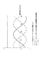
図5は、U相のコイルの温度が他の2相のコイルの各温度よりも高い状態でインバータ117が2相通電を行った際、DCDCコンバータ123が目標直流電圧指令Vcu**に応じて昇圧動作を行ったときにインバータ117が電動機10に供給する各相電流、及び、目標直流電圧指令Vcu**に応じてDCDCコンバータ123が出力する電圧を示すグラフである。なお、目標直流電圧指令Vcu**に応じたDCDCコンバータ123の出力電圧は一定とする。
FIG. 5 shows that when the
U相のコイル温度が他の2相の各コイル温度よりも高い状態のとき、U相コイルに設けられた巻線の抵抗成分は他相コイルの巻線の抵抗成分よりも大きい。このとき、図5に示すように、インバータ117が電動機10に供給する相電流間には偏りが発生する、又はこのような偏りが発生する可能性が高い。電圧指令出力部303は、インバータ117が出力する3相の電流値が均等になるよう、相抵抗情報に基づく電気角度θmに応じた昇圧率の調整を出力電圧指令Vcu***によって行う。
When the U-phase coil temperature is higher than the other two-phase coil temperatures, the resistance component of the winding provided in the U-phase coil is larger than the resistance component of the winding of the other-phase coil. At this time, as shown in FIG. 5, there is a high possibility that deviation occurs between the phase currents supplied to the
図6は、U相のコイルの温度が他の2相のコイルの各温度よりも高い状態でインバータ117が2相通電を行った際、DCDCコンバータ123が出力電圧指令Vcu***に応じて昇圧動作を行ったときに電動機10に供給される各相電流、並びに、目標直流電圧指令Vcu**及び出力電圧指令Vcu***に応じてDCDCコンバータ123が出力する各電圧を示すグラフである。図6に示すように、出力電圧指令Vcu***に応じたDCDCコンバータ123の出力電圧によって、目標直流電圧指令Vcu**に応じたDCDCコンバータ123の出力電圧の場合と比較して、インバータ117から出力される3相の電流値は電気角度θmによらず均等になる。
FIG. 6 shows that when the
以上説明したように、本実施形態の電動機の制御装置によれば、1PLS制御時のインバータ117が2相通電を行った際の相電流間に偏りが発生する、又はその可能性があるときは、相抵抗情報に基づいてDCDCコンバータ123の変圧率が電動機10の回転子の電気角度θmに応じて変更される。その結果、インバータ117が出力する3相の電流値は等しくなるため、電動機10には相電流間の偏りによるトルクの変動が起こらず、インバータ117のスイッチング素子が過昇温によって破損することもない。したがって、電動機10の運転効率良く駆動できる。
As described above, according to the motor control device of the present embodiment, when the
なお、上記実施形態では、出力電圧指令生成部121は、電動機10の回転子の電気角度θmと同期して出力電圧指令Vcu***を出力しているが、電流センサー103が検出した電動機10の固定子に供給される3相電流と同期して出力電圧指令Vcu***を出力しても良い。また、なお、本実施形態のDCDCコンバータ123は昇降圧コンバータであるが、昇圧コンバータ又は降圧コンバータであっても良い。
In the above embodiment, the output voltage
上記実施形態では、通電形態切替部157が、3相交流電流Iu,Iv,Iw又は各相のコイル温度に基づいて、相電流間に偏りが発生した状態又は相電流間に偏りが発生する可能性が高い状態か否かを判断している。他の実施形態として、通電形態切替部157は、電動機10の固定子を構成する各相コイルのインダクタンスに基づいて、相電流間に偏りが発生した状態又は相電流間に偏りが発生する可能性が高い状態か否かを判断しても良い。インダクタンスが上がるとインピーダンスも上がるため、相電流間に偏りが発生する可能性が高い。また、通電形態切替部157は、各相コイルのインダクタンスの内、いずれか1つのインダクタンスがしきい値以上のとき、相電流が偏る可能性が高い状態と判断しても良い。
In the above-described embodiment, the energization
各相コイルのインダクタンスは、通電形態切替部157が以下の式(1)を用いて、相毎に算出する。なお、抵抗Rは、q軸電機子及びd軸電機子の抵抗であり、予め設定された固定値である。また、d軸成分のインダクタンスLdは相電流の大きさに対して一定である。
The inductance of each phase coil is calculated for each phase by the energization

また、他の実施形態として、通電形態切替部157は、各相コイルの巻線の抵抗成分に基づいて、相電流間に偏りが発生した状態又は相電流間に偏りが発生する可能性が高い状態か否かを判断しても良い。また、通電形態切替部157は、各相コイルの巻線の抵抗成分の内、いずれか1つの抵抗成分がしきい値以上のとき、相電流が偏る可能性が高い状態と判断しても良い。各相コイルの巻線の抵抗成分は、通電形態切替部157が以下の式(2)及び式(3)の連立方程式を用いて、相毎に算出する。なお、Keは誘起電圧定数である。
Further, as another embodiment, the energization
10 電動機
15 蓄電器
101 レゾルバ
103 電流センサー
105 バンドパスフィルタ(BPF)
107 3相−dp変換部
109 電流指令算出部
111 d軸電流制御部
113 q軸電流制御部
115 rθ変換部
117 インバータ
119 角速度算出部
123 DCDCコンバータ
125 出力電圧検出部
127 インバータ演算方式決定部
151 出力電圧指令生成部
153 出力電流検出部
155 温度センサー
157 通電形態切替判断部
159 抵抗増加相判断部
201 最大電圧円算出部
203 出力電圧円算出部
205 切替フラグ出力部
301 目標直流電圧指令生成部
303 電圧指令出力部
DESCRIPTION OF
107 three-phase-
Claims (9)
前記電動機の前記固定子に相電流を供給して前記電動機を駆動するインバータと、
直流電源の出力電圧を昇圧又は降圧して前記インバータに印加する電圧変換部と、
前記電圧変換部の出力電圧を指示するための出力電圧指令を生成する出力電圧指令生成部と、
矩形波制御時に前記インバータが行う通電形態を切り替える通電形態切替部と、
前記電動機の前記回転子の電気角度を取得する電気角度取得部と、
前記インバータが前記電動機に供給する相電流間に偏りが発生した第1の状態、又は前記相電流間に偏りが発生する条件を満たす第2の状態を検出する状態検出部と、を備え、
前記状態検出部が前記第1の状態又は前記第2の状態を検出したとき、前記通電形態切替部は、前記通電形態を2相通電に切り替え、かつ、前記出力電圧指令生成部は、前記電気角度取得部が取得した前記回転子の電気角度の変化に同期して前記相電流間の偏りを補正するよう指示する前記出力電圧指令を生成することを特徴とする電動機の制御装置。 A control device for an electric motor having a rotor, and a stator that rotates a rotor by generating a rotating magnetic field by an applied voltage,
An inverter that drives the electric motor by supplying a phase current to the stator of the electric motor;
A voltage converter for stepping up or stepping down the output voltage of the DC power source and applying it to the inverter;
An output voltage command generator for generating an output voltage command for instructing an output voltage of the voltage converter;
An energization mode switching unit that switches an energization mode performed by the inverter during rectangular wave control;
An electrical angle acquisition unit for acquiring an electrical angle of the rotor of the electric motor;
A first state in which a bias has occurred between the phase currents supplied to the electric motor by the inverter, or a state detection unit that detects a second state that satisfies a condition in which the bias occurs between the phase currents,
When the state detection unit detects the first state or the second state, the energization mode switching unit switches the energization mode to two-phase energization, and the output voltage command generation unit The motor control device according to claim 1, wherein the output voltage command is generated to instruct to correct the bias between the phase currents in synchronization with a change in the electrical angle of the rotor acquired by the angle acquisition unit.
前記電動機の前記固定子に相電流を供給して前記電動機を駆動するインバータと、
直流電源の出力電圧を昇圧又は降圧して前記インバータに印加する電圧変換部と、
前記電圧変換部の出力電圧を指示するための出力電圧指令を生成する出力電圧指令生成部と、
矩形波制御時に前記インバータが行う通電形態を切り替える通電形態切替部と、
前記インバータが前記電動機に供給する相電流間に偏りが発生した第1の状態、又は前記相電流間に偏りが発生する条件を満たす第2の状態を検出する状態検出部と、を備え、
前記状態検出部が前記第1の状態又は前記第2の状態を検出したとき、前記通電形態切替部は、前記通電形態を2相通電に切り替え、かつ、前記出力電圧指令生成部は、前記電動機に供給される前記相電流の変化に同期して前記相電流間の偏りを補正するよう指示する前記出力電圧指令を生成することを特徴とする電動機の制御装置。 A control device for an electric motor having a rotor, and a stator that rotates a rotor by generating a rotating magnetic field by an applied voltage,
An inverter that drives the electric motor by supplying a phase current to the stator of the electric motor;
A voltage converter for stepping up or stepping down the output voltage of the DC power source and applying it to the inverter;
An output voltage command generator for generating an output voltage command for instructing an output voltage of the voltage converter;
An energization mode switching unit that switches an energization mode performed by the inverter during rectangular wave control;
A first state in which a bias has occurred between the phase currents supplied to the electric motor by the inverter, or a state detection unit that detects a second state that satisfies a condition in which the bias occurs between the phase currents,
When the state detection unit detects the first state or the second state, the energization mode switching unit switches the energization mode to two-phase energization, and the output voltage command generation unit includes the electric motor A control apparatus for an electric motor, wherein the output voltage command is generated to instruct to correct a deviation between the phase currents in synchronization with a change in the phase current supplied to the motor.
前記状態検出部は、前記相電流を検出する相電流検出部を含み、
前記相電流検出部が検出した相電流の内、いずれか1つの相電流の積算電流値と他の相電流の積算電流値との差がしきい値以上のとき、当該制御装置が前記第1の状態と検出することを特徴とする電動機の制御装置。 The motor control device according to claim 1 or 2,
The state detection unit includes a phase current detection unit that detects the phase current,
When the difference between the accumulated current value of any one of the phase currents detected by the phase current detection unit and the accumulated current value of the other phase currents is greater than or equal to a threshold value, the control device A control device for an electric motor characterized by detecting the state of the motor.
前記状態検出部は、前記固定子の各相に対応する部分の温度を検出する温度検出部を含み、
前記温度検出部が検出した温度の内、いずれか1つの温度と他の温度との差がしきい値以上のとき、当該制御装置が前記第2の状態と検出することを特徴とする電動機の制御装置。 The motor control device according to claim 1 or 2,
The state detection unit includes a temperature detection unit that detects a temperature of a portion corresponding to each phase of the stator,
When the difference between any one of the temperatures detected by the temperature detection unit and the other temperature is equal to or greater than a threshold value, the control device detects the second state. Control device.
前記状態検出部は、前記固定子の各相に対応する部分の温度を検出する温度検出部を含み、
前記温度検出部が検出した温度の内、いずれか1つの温度がしきい値以上のとき、当該制御装置が前記第2の状態と検出することを特徴とする電動機の制御装置。 The motor control device according to claim 1 or 2,
The state detection unit includes a temperature detection unit that detects a temperature of a portion corresponding to each phase of the stator,
The motor control device, wherein when any one of the temperatures detected by the temperature detection unit is equal to or higher than a threshold value, the control device detects the second state.
前記状態検出部は、前記固定子を構成する各相コイルのインダクタンスを導出するインダクタンス導出部を含み、
前記インダクタンス導出部が導出した各相コイルのインダクタンスの内、いずれか1つのインダクタンスと他のインダクタンスとの差がしきい値以上のとき、当該制御装置が前記第2の状態と検出することを特徴とする電動機の制御装置。 The motor control device according to claim 1 or 2,
The state detection unit includes an inductance deriving unit for deriving the inductance of each phase coil constituting the stator,
When the difference between any one of the inductances of each phase coil derived by the inductance deriving unit and the other inductance is equal to or greater than a threshold value, the control device detects the second state. An electric motor control device.
前記状態検出部は、前記固定子を構成する各相コイルのインダクタンスを導出するインダクタンス導出部を含み、
前記インダクタンス導出部が導出した各相コイルのインダクタンスの内、いずれか1つのインダクタンスがしきい値以上のとき、当該制御装置が前記第2の状態と検出することを特徴とする電動機の制御装置。 The motor control device according to claim 1 or 2,
The state detection unit includes an inductance deriving unit for deriving the inductance of each phase coil constituting the stator,
The control device for an electric motor, wherein when any one of the inductances of the respective phase coils derived by the inductance deriving unit is equal to or greater than a threshold value, the control device detects the second state.
前記状態検出部は、前記固定子を構成する各相コイルの巻線の抵抗成分を導出する抵抗成分導出部を含み、
前記抵抗成分導出部が導出した各相コイルの巻線の抵抗成分の内、いずれか1つの抵抗成分と他の抵抗成分との差がしきい値以上のとき、当該制御装置が前記第2の状態と検出することを特徴とする電動機の制御装置。 The motor control device according to claim 1 or 2,
The state detection unit includes a resistance component deriving unit for deriving a resistance component of a winding of each phase coil constituting the stator,
When the difference between any one of the resistance components of the coils of each phase coil derived by the resistance component deriving unit and the other resistance component is equal to or greater than a threshold value, the control device An electric motor control device that detects a state.
前記状態検出部は、前記固定子を構成する各相コイルの巻線の抵抗成分を導出する抵抗成分導出部を含み、
前記抵抗成分導出部が導出した各相コイルの巻線の抵抗成分の内、いずれか1つの抵抗成分がしきい値以上のとき、当該制御装置が前記第2の状態と検出することを特徴とする電動機の制御装置。 The motor control device according to claim 1 or 2,
The state detection unit includes a resistance component deriving unit for deriving a resistance component of a winding of each phase coil constituting the stator,
The control device detects the second state when any one of the resistance components of the winding of each phase coil derived by the resistance component deriving unit is greater than or equal to a threshold value. The motor control device.
Priority Applications (1)
| Application Number | Priority Date | Filing Date | Title |
|---|---|---|---|
| JP2009104925A JP5317812B2 (en) | 2009-04-23 | 2009-04-23 | Electric motor control device |
Applications Claiming Priority (1)
| Application Number | Priority Date | Filing Date | Title |
|---|---|---|---|
| JP2009104925A JP5317812B2 (en) | 2009-04-23 | 2009-04-23 | Electric motor control device |
Publications (2)
| Publication Number | Publication Date |
|---|---|
| JP2010259180A JP2010259180A (en) | 2010-11-11 |
| JP5317812B2 true JP5317812B2 (en) | 2013-10-16 |
Family
ID=43319466
Family Applications (1)
| Application Number | Title | Priority Date | Filing Date |
|---|---|---|---|
| JP2009104925A Expired - Fee Related JP5317812B2 (en) | 2009-04-23 | 2009-04-23 | Electric motor control device |
Country Status (1)
| Country | Link |
|---|---|
| JP (1) | JP5317812B2 (en) |
Families Citing this family (1)
| Publication number | Priority date | Publication date | Assignee | Title |
|---|---|---|---|---|
| JP6070430B2 (en) * | 2013-06-18 | 2017-02-01 | 株式会社明電舎 | Two-stage change prevention method and apparatus for serial multiple inverter control device |
Family Cites Families (4)
| Publication number | Priority date | Publication date | Assignee | Title |
|---|---|---|---|---|
| JP2001037282A (en) * | 1999-07-15 | 2001-02-09 | Toyota Motor Corp | Electric control device for polyphase AC motor |
| JP2005027391A (en) * | 2003-06-30 | 2005-01-27 | Mitsuba Corp | Driver of brushless motor |
| JP4280573B2 (en) * | 2003-07-31 | 2009-06-17 | トヨタ自動車株式会社 | Load drive device |
| JP5047582B2 (en) * | 2006-10-18 | 2012-10-10 | 東芝キヤリア株式会社 | Inverter device |
-
2009
- 2009-04-23 JP JP2009104925A patent/JP5317812B2/en not_active Expired - Fee Related
Also Published As
| Publication number | Publication date |
|---|---|
| JP2010259180A (en) | 2010-11-11 |
Similar Documents
| Publication | Publication Date | Title |
|---|---|---|
| US9325274B2 (en) | Apparatus for carrying out improved control of rotary machine | |
| JP5862125B2 (en) | Control device for power converter | |
| US9621093B2 (en) | Motor control device | |
| US9543868B2 (en) | Apparatus for controlling rotary electric machine | |
| US20160028339A1 (en) | Apparatus for controlling rotary machine | |
| US9755563B2 (en) | Inverter control apparatus and inverter apparatus | |
| EP2763309A2 (en) | Inverter apparatus and method of controlling inverter apparatus | |
| CN112204873B (en) | Permanent magnet synchronous motor control device, electric vehicle and magnetic pole polarity distinguishing method | |
| US20190097559A1 (en) | Power conversion device, motor drive device, and refrigerator using same | |
| KR101514391B1 (en) | Vector controller and motor controller using the same, air-conditioner | |
| JP6425898B2 (en) | Inverter control device and method thereof | |
| JP2015109777A (en) | Motor control device | |
| JP5196269B2 (en) | Electric motor control device | |
| US9240744B2 (en) | Methods, systems and apparatus for adjusting current and/or torque commands used to control operation of an asynchronous machine | |
| JP2009189146A (en) | Control unit for electric motor | |
| JP2019146360A (en) | Inverter controller | |
| JP5888148B2 (en) | Rotating machine control device | |
| JP2009273302A (en) | Controller for electric motor | |
| JP5366634B2 (en) | Electric motor control device | |
| JP2018042315A (en) | Inverter controller | |
| JP5317812B2 (en) | Electric motor control device | |
| US9948220B2 (en) | Rotation angle estimation apparatus for rotating electric machine | |
| JP2005130608A (en) | Motor controller | |
| JP2020014266A (en) | Control device for electric motor | |
| JP2005229736A (en) | Motor drive unit and air conditioner using the same |
Legal Events
| Date | Code | Title | Description |
|---|---|---|---|
| A621 | Written request for application examination |
Free format text: JAPANESE INTERMEDIATE CODE: A621 Effective date: 20111125 |
|
| A521 | Written amendment |
Free format text: JAPANESE INTERMEDIATE CODE: A523 Effective date: 20120522 |
|
| TRDD | Decision of grant or rejection written | ||
| A01 | Written decision to grant a patent or to grant a registration (utility model) |
Free format text: JAPANESE INTERMEDIATE CODE: A01 Effective date: 20130611 |
|
| A61 | First payment of annual fees (during grant procedure) |
Free format text: JAPANESE INTERMEDIATE CODE: A61 Effective date: 20130709 |
|
| R150 | Certificate of patent or registration of utility model |
Ref document number: 5317812 Country of ref document: JP Free format text: JAPANESE INTERMEDIATE CODE: R150 Free format text: JAPANESE INTERMEDIATE CODE: R150 |
|
| LAPS | Cancellation because of no payment of annual fees |