JP5306900B2 - Transplanted tendon anchor with bone fragment for ligament reconstruction - Google Patents
Transplanted tendon anchor with bone fragment for ligament reconstruction Download PDFInfo
- Publication number
- JP5306900B2 JP5306900B2 JP2009121363A JP2009121363A JP5306900B2 JP 5306900 B2 JP5306900 B2 JP 5306900B2 JP 2009121363 A JP2009121363 A JP 2009121363A JP 2009121363 A JP2009121363 A JP 2009121363A JP 5306900 B2 JP5306900 B2 JP 5306900B2
- Authority
- JP
- Japan
- Prior art keywords
- bone
- hole
- fixing member
- fixing
- graft
- Prior art date
- Legal status (The legal status is an assumption and is not a legal conclusion. Google has not performed a legal analysis and makes no representation as to the accuracy of the status listed.)
- Active
Links
Images


Classifications
-
- A—HUMAN NECESSITIES
- A61—MEDICAL OR VETERINARY SCIENCE; HYGIENE
- A61F—FILTERS IMPLANTABLE INTO BLOOD VESSELS; PROSTHESES; DEVICES PROVIDING PATENCY TO, OR PREVENTING COLLAPSING OF, TUBULAR STRUCTURES OF THE BODY, e.g. STENTS; ORTHOPAEDIC, NURSING OR CONTRACEPTIVE DEVICES; FOMENTATION; TREATMENT OR PROTECTION OF EYES OR EARS; BANDAGES, DRESSINGS OR ABSORBENT PADS; FIRST-AID KITS
- A61F2/00—Filters implantable into blood vessels; Prostheses, i.e. artificial substitutes or replacements for parts of the body; Appliances for connecting them with the body; Devices providing patency to, or preventing collapsing of, tubular structures of the body, e.g. stents
- A61F2/02—Prostheses implantable into the body
- A61F2/08—Muscles; Tendons; Ligaments
- A61F2/0805—Implements for inserting tendons or ligaments
-
- A—HUMAN NECESSITIES
- A61—MEDICAL OR VETERINARY SCIENCE; HYGIENE
- A61B—DIAGNOSIS; SURGERY; IDENTIFICATION
- A61B17/00—Surgical instruments, devices or methods
- A61B17/16—Instruments for performing osteoclasis; Drills or chisels for bones; Trepans
- A61B17/1604—Chisels; Rongeurs; Punches; Stamps
-
- A—HUMAN NECESSITIES
- A61—MEDICAL OR VETERINARY SCIENCE; HYGIENE
- A61B—DIAGNOSIS; SURGERY; IDENTIFICATION
- A61B17/00—Surgical instruments, devices or methods
- A61B17/56—Surgical instruments or methods for treatment of bones or joints; Devices specially adapted therefor
- A61B17/58—Surgical instruments or methods for treatment of bones or joints; Devices specially adapted therefor for osteosynthesis, e.g. bone plates, screws or setting implements
- A61B17/68—Internal fixation devices, including fasteners and spinal fixators, even if a part thereof projects from the skin
- A61B17/84—Fasteners therefor or fasteners being internal fixation devices
- A61B17/86—Pins or screws or threaded wires; nuts therefor
- A61B17/8625—Shanks, i.e. parts contacting bone tissue
- A61B17/8635—Tips of screws
-
- A—HUMAN NECESSITIES
- A61—MEDICAL OR VETERINARY SCIENCE; HYGIENE
- A61B—DIAGNOSIS; SURGERY; IDENTIFICATION
- A61B17/00—Surgical instruments, devices or methods
- A61B17/56—Surgical instruments or methods for treatment of bones or joints; Devices specially adapted therefor
- A61B17/58—Surgical instruments or methods for treatment of bones or joints; Devices specially adapted therefor for osteosynthesis, e.g. bone plates, screws or setting implements
- A61B17/68—Internal fixation devices, including fasteners and spinal fixators, even if a part thereof projects from the skin
- A61B17/84—Fasteners therefor or fasteners being internal fixation devices
- A61B17/86—Pins or screws or threaded wires; nuts therefor
- A61B17/864—Pins or screws or threaded wires; nuts therefor hollow, e.g. with socket or cannulated
-
- A—HUMAN NECESSITIES
- A61—MEDICAL OR VETERINARY SCIENCE; HYGIENE
- A61B—DIAGNOSIS; SURGERY; IDENTIFICATION
- A61B17/00—Surgical instruments, devices or methods
- A61B17/56—Surgical instruments or methods for treatment of bones or joints; Devices specially adapted therefor
- A61B17/58—Surgical instruments or methods for treatment of bones or joints; Devices specially adapted therefor for osteosynthesis, e.g. bone plates, screws or setting implements
- A61B17/88—Osteosynthesis instruments; Methods or means for implanting or extracting internal or external fixation devices
- A61B17/92—Impactors or extractors, e.g. for removing intramedullary devices
- A61B2017/922—Devices for impaction, impact element
Landscapes
- Health & Medical Sciences (AREA)
- Orthopedic Medicine & Surgery (AREA)
- Life Sciences & Earth Sciences (AREA)
- Surgery (AREA)
- General Health & Medical Sciences (AREA)
- Animal Behavior & Ethology (AREA)
- Engineering & Computer Science (AREA)
- Biomedical Technology (AREA)
- Heart & Thoracic Surgery (AREA)
- Veterinary Medicine (AREA)
- Public Health (AREA)
- Medical Informatics (AREA)
- Molecular Biology (AREA)
- Nuclear Medicine, Radiotherapy & Molecular Imaging (AREA)
- Neurology (AREA)
- Oral & Maxillofacial Surgery (AREA)
- Dentistry (AREA)
- Rehabilitation Therapy (AREA)
- Rheumatology (AREA)
- Cardiology (AREA)
- Transplantation (AREA)
- Vascular Medicine (AREA)
- Surgical Instruments (AREA)
- Prostheses (AREA)
Abstract
Description
本発明は、靱帯再建術において骨片付き移植腱を移植対象部位に形成された骨孔内にて固定する靱帯再建術用骨片付き移植腱固定具に関するものである。 The present invention relates to a graft tendon fixation device with a bone fragment for ligament reconstruction for fixing a graft tendon with a bone fragment in a bone hole formed in a site to be transplanted in ligament reconstruction.
現在行われている靭帯再建術(例えば、膝前十字靱帯再建術)では、脛骨側に第1の骨トンネル(脛骨側骨孔)を形成し、大腿骨側に第2の骨トンネル(大腿骨側骨孔)を作成する。通常、再建用移植腱(例:4−6重折ハムストリング筋腱)の長さが、第1の骨トンネル−関節内−第2の骨トンネルを通過するのに充分でないため、その両端に人工靭帯や縫合糸を装着し、大腿骨側骨孔の上方口付近にて靭帯を固定した後、脛骨側骨孔の前方口にて最終固定を行っている。
また、再建用靭帯として、自家骨片付き膝蓋腱を再建靱帯として用いる方法も広く行われている。この骨片付き膝蓋腱を用いた手技としては、米国公開公報2007/0032870において開示される、先端から基端までにねじ山を備え基端に平面を備えた骨孔内移植靱帯固定螺子および、EP公開公報1297799において開示される、膨張可能な移植腱固定装置を脛骨側骨孔と再建用靭帯の脛骨側骨片との間に挿入して固定するもの、USP6117139において開示される2本のスパイクと結紮孔を備えた移植靱帯固定用器具を脛骨側骨孔付近に打ち込んで結紮孔に再建用靭帯の脛骨側骨片に縫着された縫合糸を結びつけて固定するもの、脛骨側骨孔付近にスクリューを挿入してその頭部に再建用靭帯の脛骨側骨片に縫着された縫合糸を結びつけて固定するもの等が利用されている。
In ligament reconstruction currently performed (for example, anterior cruciate ligament reconstruction), a first bone tunnel (tibial side bone hole) is formed on the tibia side, and a second bone tunnel (femur) is formed on the femur side. Side bone hole). Usually, the length of the reconstruction graft tendon (eg 4-6 folded hamstring muscle tendon) is not sufficient to pass through the first bone tunnel-intra-articular-second bone tunnel, An artificial ligament or suture is attached and the ligament is fixed in the vicinity of the upper mouth of the femoral bone hole, and then finally fixed at the front mouth of the tibial bone hole.
In addition, as a ligament for reconstruction, a method of using a patella tendon with an autologous bone piece as a reconstruction ligament has been widely performed. As a procedure using this patellar tendon with a bone fragment, disclosed in U.S. Publication No. 2007/0032870, an intraosseous ligament fixation screw having a screw thread from the distal end to the proximal end and a flat surface at the proximal end, and EP An inflatable graft tendon fixation device disclosed in publication 1297799 is inserted and fixed between a tibial bone hole and a tibial bone fragment of a reconstruction ligament, two spikes disclosed in US Pat. No. 6,117,139, and Implanting a ligament fixation device with a ligation hole near the tibial bone hole and fixing the ligation hole with a suture thread sewn to the tibial bone fragment of the ligament for reconstruction, near the tibial bone hole For example, a screw inserted into the head and a suture thread sewn to the tibia bone fragment of the ligament for reconstruction is connected and fixed.
しかし、上記固定器具では、再建用靭帯を術者の意図した張力にて固定することが困難であるという問題点があった。
本発明の課題は、上記の問題点を解決し、骨片付き移植腱を術者の意図した張力で固定できる靱帯再建術用骨片付き移植腱固定具を提供するものである。
However, the fixing device has a problem that it is difficult to fix the ligament for reconstruction with the tension intended by the operator.
An object of the present invention is to solve the above-mentioned problems and to provide a bone graft graft tendon fixing tool for ligament reconstruction that can fix the bone graft graft tendon with a tension intended by an operator.
上記目的を達成するものは、以下のものである。
(1) 少なくとも一方の端部に骨片を備えかつ他方の端部が移植対象部位に固定された骨片付き移植腱の前記骨片を、前記移植対象部位に形成された骨孔内にて固定するための靱帯再建術用骨片付き移植腱固定具であって、
前記固定具は、中央部に設けられた貫通孔を有する本体部と、前記本体部の両側部よりほぼ平行に延びかつ形成される前記骨孔の径よりも所定長離間するように設けられた骨に打ち込み可能な2本のスパイク部とを備える固定部材と、前記固定部材の前記貫通孔を貫通可能かつ前記骨片に螺入するためのセルフタップ部および雄ねじ部を有するシャフト部と、該シャフト部の基端に位置し、前記固定部材の前記貫通孔の周縁にて前記本体部と当接可能な頭部と、該頭部の基端から前記シャフト部の先端まで延び、前記骨片に刺入されるガイドピンが貫通可能な内腔とを備える固定螺子とからなり、
さらに、前記固定部材は、前記本体部が前記骨孔の開口を横切るように前記骨孔付近に打ち込まれた状態にて、前記固定部材の前記貫通孔が前記骨孔の開口の中心付近に位置し、かつ、前記骨片付き移植腱に取り付けられた牽引用部材を前記本体部と前記骨孔の開口との間より延出可能であり、
前記固定螺子は、前記骨片に刺入されるガイドピンが該固定螺子の前記内腔を貫通し、かつ、前記骨片付き移植腱に取り付けられかつ前記固定部材の前記本体部と前記骨孔の開口より延出した前記牽引用部材を牽引した状態にて、前記固定部材の前記貫通孔を貫通し前記骨片に螺入可能であり、さらに、前記固定螺子の前記頭部の前記固定部材の前記貫通孔付近への当接後の該固定螺子の前記骨片への螺入量を調整することにより、前記移植対象部位に移植された前記移植腱の張力調整が可能である靱帯再建術用骨片付き移植腱固定具。
What achieves the above object is as follows.
(1) Fixing the bone fragment of a graft tendon with a bone fragment having a bone fragment at least at one end and the other end fixed to the site to be transplanted in a bone hole formed at the site to be transplanted A graft tendon fixation device with a bone fragment for ligament reconstruction for
The fixing device is provided so as to be separated by a predetermined length from a main body portion having a through hole provided in a central portion and a diameter of the bone hole extending and formed substantially parallel to both side portions of the main body portion. A fixing member comprising two spike parts that can be driven into a bone, a shaft part that can penetrate the through hole of the fixing member and has a self-tap part and a male screw part for screwing into the bone fragment; A head located at the base end of the shaft portion and capable of contacting the body portion at the periphery of the through-hole of the fixing member; and extending from the base end of the head portion to the tip of the shaft portion; A fixing screw having a lumen through which a guide pin inserted into the
Further, in the fixing member, the through hole of the fixing member is positioned near the center of the opening of the bone hole in a state where the main body portion is driven in the vicinity of the bone hole so as to cross the opening of the bone hole. And a traction member attached to the bone graft graft tendon can be extended from between the body portion and the opening of the bone hole,
In the fixing screw, a guide pin inserted into the bone fragment passes through the lumen of the fixing screw, and is attached to the graft tendon with the bone fragment, and between the main body portion of the fixing member and the bone hole In a state where the pulling member extending from the opening is pulled, the fixing member can pass through the through hole of the fixing member and be screwed into the bone fragment, and further, the fixing member of the head of the fixing screw For ligament reconstruction surgery, the tension of the transplanted tendon transplanted to the transplant target site can be adjusted by adjusting the screwing amount of the fixing screw into the bone fragment after contact with the vicinity of the through hole. A graft tendon fixator with bone fragments.
(2) 前記靱帯再建術は、膝前十字靱帯再建術であり、前記移植対象部位に形成される前記骨孔は、大腿骨側骨孔と脛骨側骨孔とを備えるものであり、前記移植腱固定具は、前記脛骨側骨孔内にて前記移植腱の骨片を固定するものである上記(1)に記載の靱帯再建術用骨片付き移植腱固定具。
(3) 前記固定部材は、前記スパイク部の形成側の前記貫通孔の周辺に設けられ、前記骨孔の内壁面に摺接もしくは近接するように侵入可能である骨孔保護用突起部を備えている上記(1)または(2)に記載の靱帯再建術用骨片付き移植腱固定具。
(4) 前記スパイク部は、向かい合う内側の形状と外側の形状が異なるものである上記(1)ないし(3)のいずれかに記載の靱帯再建術用骨片付き移植腱固定具。
(5) 前記スパイク部は、向かい合う内側が実質的に角部を持たない曲面形状となっている上記(4)に記載の靱帯再建術用骨片付き移植腱固定具。
(6) 前記固定部材の前記貫通孔は、前記スパイク部の形成側に向かってテーパー状に縮径する開口部と、該開口部と連続し、かつねじ溝を持たない孔部とを備え、前記固定螺子の前記頭部は、下部周縁部に形成された先端側に向かって縮径するテーパー部を備え、該テーパー部は、前記固定部材のテーパー状に縮径する前記開口部と当接もしくは前記開口部内に侵入可能なものとなっている上記(1)ないし(5)のいずれかに記載の靱帯再建術用骨片付き移植腱固定具。
(2) The ligament reconstruction is an anterior cruciate ligament reconstruction, and the bone hole formed in the transplant target site includes a femoral side bone hole and a tibial side bone hole, and the transplantation The tendon fixation device with a bone fragment for ligament reconstruction as described in (1) above, wherein the tendon fixation device fixes a bone fragment of the graft tendon within the tibial bone hole.
(3) The fixing member includes a projection for protecting a bone hole provided around the through hole on the side where the spike is formed, and capable of entering so as to slide or approach the inner wall surface of the bone hole. The graft tendon fixation device with a bone fragment for ligament reconstruction as described in (1) or (2) above.
(4) The above-mentioned spike part is a graft tendon fixing device with a bone fragment for ligament reconstruction according to any one of the above (1) to (3), wherein the inner shape and the outer shape facing each other are different.
(5) The above-mentioned spike part is a graft tendon fixing device with a bone fragment for ligament reconstruction as described in (4) above, wherein the facing inner side has a curved surface shape having substantially no corner part.
(6) The through hole of the fixing member includes an opening that is tapered in a tapered shape toward the spike forming side, and a hole that is continuous with the opening and has no thread groove. The head portion of the fixing screw includes a tapered portion formed in a lower peripheral portion and having a diameter reduced toward a tip end side, and the tapered portion is in contact with the opening portion of the fixing member having a reduced diameter. Alternatively, the graft tendon fixing device with a bone fragment for ligament reconstruction according to any one of the above (1) to (5), which is capable of entering the opening.
また、上記目的を達成するものは、以下のものである。
(7) 少なくとも一方の端部に骨片を備えかつ他方の端部が移植対象部位に固定された骨片付き移植腱の前記骨片を、前記移植対象部位に形成された骨孔内にて固定するための骨片付き移植腱固定具と、該移植腱固定具を骨に打ち込むための打ち込み器とからなる靱帯再建術用骨片付き移植腱固定器具であって、
前記固定具は、中央部に設けられた貫通孔を有する本体部と、前記本体部の両側部よりほぼ平行に延びかつ形成される前記骨孔の径よりも所定長離間するように設けられた骨に打ち込み可能な2本のスパイク部とを備える固定部材と、前記固定部材の前記貫通孔を貫通可能かつ前記骨片に螺入するためのセルフタップ部および雄ねじ部を有するシャフト部と、該シャフト部の基端に位置し、前記固定部材の前記貫通孔の周縁にて前記本体部と当接可能な頭部と、該頭部の基端から前記シャフト部の先端まで延び、前記骨片に刺入されるガイドピンが貫通可能な内腔とを備える固定螺子とからなり、
さらに、前記固定部材は、前記本体部が前記骨孔の開口を横切るように前記骨孔付近に打ち込まれた状態にて、前記固定部材の前記貫通孔が前記骨孔の開口の中心付近に位置し、かつ、前記骨片付き移植腱に取り付けられた牽引用部材を前記本体部と前記骨孔の開口との間より延出可能であり、前記固定螺子は、前記骨片に刺入されるガイドピンが該固定螺子の前記内腔を貫通し、かつ、前記骨片付き移植腱に取り付けられかつ前記固定部材の前記本体部と前記骨孔の開口より延出した前記牽引用部材を牽引した状態にて、前記固定部材の前記貫通孔を貫通し前記骨片に螺入可能であり、さらに、前記固定螺子の前記頭部の前記固定部材の前記貫通孔付近への当接後の該固定螺子の前記骨片への螺入量を調整することにより、前記移植対象部位に移植された前記移植腱の張力調整が可能であり、
前記打ち込み器は、所定長延びるシャフト部と、前記シャフト部の先端に設けられた前記固定部材の前記本体部を着脱可能に把持する固定部材把持部と、前記シャフト部の基端に設けられた殴打可能部とを備える靱帯再建術用骨片付き移植腱固定器具。
Moreover, what achieves the said objective is as follows.
(7) Fixing the bone fragment of a bone graft graft tendon having a bone fragment at least at one end and the other end fixed to the site to be transplanted in a bone hole formed at the site to be transplanted A graft tendon fixation device with a bone fragment for ligament reconstruction, comprising: a graft tendon fixation device with a bone piece for performing; and a driving device for driving the graft tendon fixation device into a bone,
The fixing device is provided so as to be separated by a predetermined length from a main body portion having a through hole provided in a central portion and a diameter of the bone hole extending and formed substantially parallel to both side portions of the main body portion. A fixing member comprising two spike parts that can be driven into a bone, a shaft part that can penetrate the through hole of the fixing member and has a self-tap part and a male screw part for screwing into the bone fragment; A head located at the base end of the shaft portion and capable of contacting the body portion at the periphery of the through-hole of the fixing member; and extending from the base end of the head portion to the tip of the shaft portion; A fixing screw having a lumen through which a guide pin inserted into the
Further, in the fixing member, the through hole of the fixing member is positioned near the center of the opening of the bone hole in a state where the main body portion is driven in the vicinity of the bone hole so as to cross the opening of the bone hole. And a pulling member attached to the bone graft graft tendon can be extended from between the body portion and the opening of the bone hole, and the fixing screw is inserted into the bone fragment. A pin passes through the lumen of the fixing screw, and is attached to the bone graft graft tendon and pulls the pulling member extending from the body portion of the fixing member and the opening of the bone hole. The fixing screw can pass through the through hole of the fixing member and be screwed into the bone fragment, and the fixing screw after the head of the fixing screw comes into contact with the vicinity of the through hole of the fixing member. By adjusting the amount of screwing into the bone fragment, the transplant target part It is possible tension adjustment of the implanted the implant tendons,
The driving device is provided at a shaft portion extending for a predetermined length, a fixing member gripping portion for detachably gripping the main body portion of the fixing member provided at a distal end of the shaft portion, and a base end of the shaft portion. A graft tendon fixation device with a bone fragment for ligament reconstruction, comprising a strikable portion.
(8) 前記打ち込み器は、前記シャフト部を前記固定部材把持部が露出するように収納する筒状部材と、該筒状部材の基端側に位置し、前記殴打可能部を備えかつ前記固定部材把持部による前記固定部材の着脱を操作する操作部とを備える上記(7)に記載の靱帯再建術用骨片付き移植腱固定器具。
(9) 前記固定部材把持部は、近接および離間可能に設けられた向かい合う一対の把持用爪部を備え、前記シャフト部は基端部に設けられた第1の螺合部を備え、前記操作部は、前記第1の螺合部と螺合可能な第2の螺合部を備え、該操作部の回転による前記第1の螺合部と前記第2の螺合部の螺合の進行により、前記一対の把持用爪部の基端部が前記筒状部材内に侵入し、前記一対の把持用爪部間が近接し前記固定部材を把持可能状態となり、かつ、前記操作部の回転による前記第1の螺合部と前記第2の螺合部の螺合の後退により、前記一対の把持用爪部間が離間し前記固定部材を開放可能となるものである上記(8)に記載の靱帯再建術用骨片付き移植腱固定器具。
(10) 前記靱帯再建術用骨片付き移植腱固定器具は、前記骨孔付近にパイロット孔を形成するためのパイロット孔形成器を備えるものであり、
前記パイロット孔形成器は、シャフト部と、該シャフト部の先端部に形成され、形成される前記骨孔内の内径とほぼ同じ外径を有する骨孔内侵入用突出部と、前記シャフト部の先端部に、前記骨孔内侵入用突出部を挟む様にかつ前記2本のスパイク部と同じ距離離間して設けられた2本の針状部とを備えるものである上記(7)ないし(9)のいずれかに記載の靱帯再建術用骨片付き移植腱固定器具。
(8) The driving device includes a cylindrical member that houses the shaft portion so that the fixing member gripping portion is exposed, and is provided on the proximal end side of the cylindrical member, and includes the strikeable portion and the fixed portion. A graft tendon fixation device with a bone fragment for ligament reconstruction as described in (7) above, comprising an operation unit for operating attachment / detachment of the fixing member by a member gripping unit.
(9) The fixing member gripping portion includes a pair of gripping claws facing each other provided so as to be able to approach and separate, and the shaft portion includes a first screwing portion provided at a base end portion, The portion includes a second screwing portion that can be screwed with the first screwing portion, and the screwing of the first screwing portion and the second screwing portion is advanced by rotation of the operation portion. As a result, the base end portions of the pair of gripping claws enter the cylindrical member, the pair of gripping claws close to each other, and the fixing member can be gripped, and the operation portion rotates. (8) in which the pair of gripping claws are separated and the fixing member can be opened by retreating the screwing of the first screwing portion and the second screwing portion. The graft tendon fixation device with a bone fragment for ligament reconstruction as described.
(10) The graft tendon fixation device with a bone fragment for ligament reconstruction is provided with a pilot hole former for forming a pilot hole in the vicinity of the bone hole,
The pilot hole forming device includes a shaft portion, a protrusion portion for intruding into a bone hole formed at a distal end portion of the shaft portion and having an outer diameter substantially the same as an inner diameter in the bone hole to be formed; (7) thru | or (7) thru | or (2) which equips a front-end | tip part with the two needle-like parts provided so that the protrusion part for penetration | invasion in a bone hole may be pinched | interposed and the same distance as the said two spike parts. 9) A graft tendon fixation device with a bone fragment for ligament reconstruction according to any one of 9).
本発明の靱帯再建術用骨片付き移植腱固定具では、少なくとも一方の端部に骨片を備えかつ他方の端部が移植対象部位に固定された骨片付き移植腱の前記骨片を、前記移植対象部位に形成された骨孔内にて固定するための靱帯再建術用骨片付き移植腱固定具であって、前記固定具は、中央部に設けられた貫通孔を有する本体部と、前記本体部の両側部よりほぼ平行に延びかつ形成される前記骨孔の径よりも所定長離間するように設けられた骨に打ち込み可能な2本のスパイク部とを備える固定部材と、前記固定部材の前記貫通孔を貫通可能かつ前記骨片に螺入するためのセルフタップ部および雄ねじ部を有するシャフト部と、該シャフト部の基端に位置し、前記固定部材の前記貫通孔の周縁にて前記本体部と当接可能な頭部と、該頭部の基端から前記シャフト部の先端まで延び、前記骨片に刺入されるガイドピンが貫通可能な内腔とを備える固定螺子とからなる。
さらに、前記固定部材は、前記本体部が前記骨孔の開口を横切るように前記骨孔付近に打ち込まれた状態にて、前記固定部材の前記貫通孔が前記骨孔の開口の中心付近に位置し、かつ、前記骨片付き移植腱に取り付けられた牽引用部材を前記本体部と前記骨孔の開口との間より延出可能である。
さらに、前記固定螺子は、前記骨片に刺入されるガイドピンが該固定螺子の前記内腔を貫通し、かつ、前記骨片付き移植腱に取り付けられかつ前記固定部材の前記本体部と前記骨孔の開口より延出した前記牽引用部材を牽引した状態にて、前記固定部材の前記貫通孔を貫通し前記骨片に螺入可能であり、さらに、前記固定螺子の前記頭部の前記固定部材の前記貫通孔付近への当接後の該固定螺子の前記骨片への螺入量を調整することにより、前記移植対象部位に移植された前記移植腱の張力調整が可能である。
このため、骨片付き移植腱を術者の意図した初期張力で固定できる。
In the graft tendon fixation device with a bone fragment for ligament reconstruction of the present invention, the bone fragment of the bone graft graft tendon provided with a bone fragment at least at one end and the other end fixed to a site to be transplanted is obtained. A graft tendon fixing device with a ligament reconstruction bone fragment for fixing in a bone hole formed in a target site, wherein the fixing device has a main body portion having a through-hole provided in a central portion, and the main body A fixing member comprising two spike portions that extend substantially in parallel from both side portions of the portion and are spaced apart by a predetermined length from the diameter of the formed bone hole, and can be driven into the bone; A shaft portion that can penetrate the through-hole and has a self-tap portion and a male screw portion for screwing into the bone fragment, is located at the base end of the shaft portion, and the periphery of the through-hole of the fixing member A head that can come into contact with the main body, and a proximal end of the head Extends to the tip of al the shaft portion, the guide pins are pierced into the bone fragments comprising a fixing screw and a lumen pierceable.
Further, in the fixing member, the through hole of the fixing member is positioned near the center of the opening of the bone hole in a state where the main body portion is driven in the vicinity of the bone hole so as to cross the opening of the bone hole. In addition, the pulling member attached to the bone graft graft tendon can be extended from between the body portion and the opening of the bone hole.
Further, the fixing screw has a guide pin inserted into the bone fragment that penetrates the lumen of the fixing screw and is attached to the graft tendon with the bone fragment, and the main body portion of the fixing member and the bone In a state where the pulling member extending from the opening of the hole is pulled, the fixing member can be screwed into the bone piece through the through hole of the fixing member, and the fixing of the head of the fixing screw can be performed. By adjusting the screwing amount of the fixing screw into the bone fragment after the member is brought into contact with the vicinity of the through hole, it is possible to adjust the tension of the transplanted tendon transplanted to the site to be transplanted.
For this reason, the graft tendon with a bone fragment can be fixed with the initial tension intended by the operator.
本発明の靱帯再建術用骨片付き移植腱固定具を図面に示した実施例を用いて説明する。
本発明の靱帯再建術用骨片付き移植腱固定具1は、少なくとも一方の端部に骨片を備えかつ他方の端部が移植対象部位に固定された骨片付き移植腱2の骨片を、移植対象部位に形成された骨孔内にて固定するためのものである。
移植腱固定具1は、中央部に設けられた貫通孔31を有する本体部32と、本体部32の両側部よりほぼ平行に延びかつ形成される骨孔の径よりも所定長離間するように設けられた骨に打ち込み可能な2本のスパイク部33、34とを備える固定部材3と、固定部材3の貫通孔31を貫通可能かつ骨片に螺入するためのセルフタップ部63および雄ねじ部62を有するシャフト部65と、シャフト部の基端に位置し、固定部材3の貫通孔31の周縁にて本体部32と当接可能な頭部61と、頭部61の基端からシャフト部65の先端まで延び、骨片に刺入されるガイドピン85が貫通可能な内腔66とを備える固定螺子6を備える。
The graft tendon fixation device with bone fragments for ligament reconstruction of the present invention will be described with reference to the embodiments shown in the drawings.
The graft
The graft
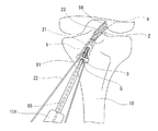
そして、この移植腱固定具1では、固定部材3は、本体部32が骨孔(脛骨側骨孔8)の開口(開口部81)を横切るように骨孔付近に打ち込まれた状態にて、貫通孔31が骨孔8の開口81の中心付近に位置し、かつ、骨片付き移植腱に取り付けられた牽引用部材22を本体部32と骨孔8の開口81との間より延出可能である。そして、固定螺子6は、骨片(一端側骨片21)に刺入されるガイドピン85が固定螺子6の内腔66を貫通し、かつ、骨片付き移植腱に取り付けられかつ固定部材3の本体部32と骨孔8の開口81より延出した牽引用部材22を牽引した状態にて、固定部材3の貫通孔31を貫通し骨片(一端側骨辺21)に螺入可能であり、さらに、固定螺子6の頭部の固定部材3の貫通孔31付近への当接後の固定螺子6の骨片21への螺入量を調整することにより、移植対象部位に移植された移植腱の張力調整が可能となっている。
In the graft
この実施例での靱帯再建術用骨片付き移植腱固定具1は、靱帯再建術に使用され、膝前十字靱帯再建術において脛骨側骨孔8内にて移植腱の骨片(一端側骨片21)を固定するのに用いることが好適である。しかし、本発明の移植腱固定具では、この手技に限らず、膝前十字靱帯再建術以外(例えば、膝後十字靱帯再建術)の靱帯再建術や、脛骨側骨孔8以外(例えば、大腿骨側骨孔9)での移植腱の骨片の固定などに用いることができる。
この実施例の移植腱固定具1に用いられる移植腱固定部材3は、図1ないし図5に示すように、本体部32と、本体部32の中央部に備えられた貫通孔31と、本体部32から延びる2本のスパイク部33,34を備える。
The graft
As shown in FIGS. 1 to 5, the graft
本体部32は、ほぼ平板状に形成されている。なお、本体部32は、屈曲板もしくは湾曲板状であってもよい。また、2本のスパイク部33,34は、本体部32の両側部よりほぼ平行に延びかつ形成される骨孔の径よりも所定長離間するように設けられている。離間距離としては、脛骨側骨孔8の開口部81の直径よりも長く、脛骨側骨孔8の開口部81周辺を破損させることなく固定部材3を脛骨10へ打ち込める程度の長さであることが好ましい。この実施例の固定部材3では、スパイク部33,34は、本体部32の両側部から2本のスパイク部がほぼ平行に、かつ、本体部32にほぼ直交するように延びている。スパイク部33,34の長さは、8〜18mm程度が好ましく、特に、11〜16mmが好適である。また、スパイク部33、34の横幅は、1.7〜2.5mm程度が好ましく、特に1.9〜2.2mmが好適である。スパイク部33,34は、先端に脛骨10に刺入するための尖端部を備えている。また、尖端部の形態としては、円錐、三角錐、四角錐等が挙げられる。また、スパイク部33,34の尖端部以外の形状は、円柱、三角柱、四角柱等が好ましい。この実施例でのスパイク部33,34の形状は、先端部が四角錐で先端部以外が四角柱となっている。スパイク部33,34の形状としては、これに限られず、内側と外側の形状が異なるものであってもよい。例えば、図8ないし図10に示す固定部材3aのように、スパイク部93,94は、向かい合う内側が実質的角部を持たない曲面形状となっていることが好ましい。このスパイク部93,94では、内側が角部を持たない円柱形状となっており、外側が角部を有する角柱形状となっている。これにより、スパイク部の脛骨10(または、後述するパイロット孔56、57)への打ち込み時に脛骨側骨孔壁に付与される衝撃を軽減することができる。
The
そして、本体部32の中央部には、後述する固定螺子6のシャフト部65を通すための貫通孔31が備えられている。そして、固定部材3は、本体部32が骨孔(脛骨側骨孔8)の開口(開口部81)を横切るように骨孔付近(脛骨側骨孔8付近)に打ち込まれた状態にて、貫通孔31が骨孔(脛骨側骨孔8)の開口(開口部81)の中心付近に位置するものとなっている。貫通孔31の形状は、円形、楕円形等が挙げられるが、特に円形であることが好ましい。この実施例での貫通孔31の形状は、円形となっている。貫通孔31の大きさは後述する固定螺子6のシャフト部65を通し、かつ、固定螺子6の頭部61が当接する直径であることが好ましい。また、貫通孔31は、スパイク部の形成側に向かってテーパー状に縮径する開口部31aと、この開口部31aと連続し、かつねじ溝を持たない孔部31bとを備えている。そして、孔部31bの内径は、後述する固定螺子のシャフト部65の外径より大きいものとなっている。また、テーパー状に縮径する開口部31aは、固定螺子6の頭部61の下部周縁部に形成された先端側に向かって縮径するテーパー部61aと当接可能もしくはテーパー部61aを収納可能なものとなっている。
A central portion of the
また、本体部32は、図8ないし図10に示す固定部材3aのように、スパイク部の形成側の貫通孔31の周辺に設けられ、骨孔(脛骨側骨孔8)の内壁面に摺接もくしは近接するように、骨孔内に侵入可能である骨孔保護用突起部95を備えるものであってもよい。このような骨孔保護用突起部95を設けることにより、脛骨側骨孔8の破損、固定部材の歪みや予期しない移動を防止することができる。
また、固定部材3の形成材料としては、例えば、ステンレス鋼(具体的には、JISG4303のSUS304、SUS316など)、純チタン(具体的には、JIST7401−1)、チタン合金(具体的には、JIST7401−2のTi−6Al−4V、ASTM F−136 Ti−6Al−4V ELI)が好ましい。
The
Further, as the forming material of the fixing
この実施例の移植腱固定具1に用いられる固定螺子6は、図1、図2、図6および、図7に示すように、固定部材3の貫通孔31を貫通可能かつ骨片に螺入するためのセルフタップ部63、雄ねじ部62を有するシャフト部65と、シャフト部65の基端に位置し、固定部材3の貫通孔31の周縁にて本体部32と当接可能な頭部61と、頭部61の基端からシャフト部65の先端まで延び、骨片に刺入されるガイドピン85が貫通可能な内腔66とを備えている。また、頭部61には、図26ないし図28に示すような螺入用器具101(具体的には、中空形状のドライバ)の先端部102に対応した形状に形成され、先端部102と係合可能な係合用溝64を備える。
シャフト部65は、側面に雄ねじ部62を備え、先端には、セルフタップ部63を備えている。セルフタップ部63は、図6に示すように、等間隔となるよう間を切り欠くことで形成された3枚の刃部63a、63b、63cによって構成されている。セルフタップ部63は、固定螺子の回転時に骨片付き移植腱2の一端側骨片21を自ら切削し、侵入するとともに、骨片21に雄ねじ部62と螺合するための雌ねじ部を形成する。シャフト部65の長さとしては、10〜30mm程度が好適であり、特に、15〜20mmが好ましい。また、シャフト部65の直径は、固定部材3の貫通孔31よりも小さく、貫通孔31を貫通できる程度の径であることが好ましい。これにより、シャフト部65は、固定部材3の貫通孔31を貫通可能となる。また、シャフト部の直径は、2〜6mm程度が好ましく、特に、3〜5mm程度が好ましい。
As shown in FIGS. 1, 2, 6, and 7, the fixing
The
また、固定螺子6の頭部61は、シャフト部65の基端に備えられ、基端側の面に螺入用器具係合用溝64が形成されている。頭部61の直径は、固定部材3の貫通孔31の直径よりも大きいものとなっている。これにより、図1に示すように、固定螺子6の頭部61は、固定部材3の貫通孔31の周縁にて本体部32と当接可能となる。つまり、固定部材3の本体部32は、固定螺子6の先端側への動きを規制することができる。
また、固定螺子6の頭部61は、下部周縁部に形成された先端側に向かって縮径するテーパー部61aを備えている。固定螺子6の頭部61の下部周縁部に形成された先端側に向かって縮径するテーパー部61aは、固定部材3のスパイク部の形成側に向かってテーパー状に縮径する開口部31aと当接可能もしくは開口部31a内に侵入可能なものとなっている。固定螺子のシャフト部65の外径は、固定部材3の貫通孔31の孔部31bの内径より小さいものとなっている。
The
In addition, the
そして、固定螺子6は、頭部61の基端からシャフト部65の先端までが貫通した内腔66を備える中空形状となっている。具体的には、図7に示すように、頭部61の係合用溝64からシャフト部65の先端に備えられたセルフタップ部63の先端まで貫通した内腔66を備える。内腔66を備えることにより、固定螺子6は、ガイドピンの挿通(貫通)が可能となっている。
これにより、固定螺子6は、骨片(一端側骨辺21)に刺入されたガイドピン85を固定螺子6の内腔66に挿通させた状態(言い換えれば、ガイドピン85が内腔66を貫通した状態)で、固定螺子6を進行させることで、固定部材3の貫通孔31を貫通可能であり、さらに、シャフト部65の先端(セルフタップ部63)を骨片(一端側骨辺21)に当接して骨片(一端側骨片21)に螺入可能状態となる。そして、固定螺子6の内腔66は、固定螺子の回転時に、ガイドピンにトルクを与えない形状となっていることが好ましい。具体的には、固定螺子6の内腔66は、軸方向に直交する方向の断面が、円形もしくは楕円形となっていることが好ましい。特に、固定螺子6の内腔66は、軸方向に直交する方向の断面が、ほぼ真円であることが好ましい。
The fixing
Thereby, the fixing
そして、固定螺子6は、固定部材3の本体部32が骨孔(脛骨側骨孔8)の開口(開口部81)を横切るように骨孔付近(脛骨側骨孔8付近)に打ち込まれた状態にて、シャフト部65が固定部材3の貫通孔31と脛骨側骨孔8の開口部81(前方口)を貫通して脛骨側骨孔8内で一端側骨片21に螺入する。そして、固定螺子6は、頭部61が固定部材3の本体部32に当接することにより、骨片付き移植腱2の他端側骨片側(または、大腿骨側の固定器具側)への動きを規制する。これにより、一端側骨片21は、脛骨側骨孔8内にて固定される。
固定螺子6の形状は、これに限られず、固定部材3の貫通孔31を貫通して骨片付き移植腱2の一端側骨片21に螺入ができ、かつ、固定部材3の本体部32に当接できる頭部をもつものであればいかなる形状であってもよい。
また、固定螺子6の形成材料としては、ステンレス鋼(具体的には、JISG4303のSUS304、SUS316など)、純チタン(具体的には、JIST7401−1)、チタン合金(具体的には、JIST7401−2のTi−6Al−4V、ASTM F−136 Ti−6Al−4V ELI)が好ましい。
また、本発明の靱帯再建術用骨片付き移植腱固定具1は、骨片付き移植腱2の一端側骨片21の固定に対して脛骨側骨孔8(骨孔内面)や牽引用部材22を利用することなく固定部材3と固定螺子6によって直接固定することができる。これにより、靱帯再建術用骨片付き移植腱固定具1は、骨孔内移植靱帯固定螺子や膨張可能な移植腱固定装置等を脛骨側骨孔8と脛骨側骨片21との間に挿入して固定するよりも固定螺子の挿入による固定位置のズレを少なくする(術者の意図した初期張力で固定する)ことができる。
The fixing
The shape of the fixing
The fixing
Moreover, the graft
次に、本発明の靱帯再建術用骨片付き移植腱固定器具について説明する。
図11は、本発明の実施例の移植腱固定器具に用いられる打ち込み器の正面図である。図12は、図11に示した打ち込み器の左側面図である。図13は、図11に示した打ち込み器の拡大底面図である。図14は、図11に示した打ち込み器のB−B線断面図である。図15は、図11に示した打ち込み器のC−C線断面図である。図16は、図11に示した打ち込み器の操作部の断面図である。図17は、図11に示した打ち込み器の移植腱固定部材把持部(シャフト部)の左側面図である。図18は、移植腱固定部材を把持した状態の打ち込み器の正面図である。図19は、図18に示した移植腱固定部材を把持した状態の打ち込み器の左側面図である。図20は、図11に示した打ち込み器の移植腱固定部材把持可能状態の拡大底面図である。図21は、図18のD−D線断面図である。
本発明の靱帯再建術用骨片付き移植腱固定器具は、少なくとも一方の端部に骨片を備えかつ他方の端部が移植対象部位に固定された骨片付き移植腱の骨片を、移植対象部位に形成された骨孔内にて固定するための骨片付き移植腱固定具1と、移植腱固定具を骨に打ち込むための打ち込み器4とからなる。
骨片付き移植腱固定具1としては、上述した通りである。
Next, the graft tendon fixation device with a bone fragment for ligament reconstruction of the present invention will be described.
FIG. 11 is a front view of a driving device used for the graft tendon fixation device of the embodiment of the present invention. FIG. 12 is a left side view of the driving tool shown in FIG. FIG. 13 is an enlarged bottom view of the driving tool shown in FIG. FIG. 14 is a cross-sectional view of the driving tool shown in FIG. 11 taken along the line BB. FIG. 15 is a cross-sectional view of the driving device shown in FIG. FIG. 16 is a cross-sectional view of the operation portion of the driving tool shown in FIG. FIG. 17 is a left side view of the graft tendon fixing member gripping portion (shaft portion) of the driving device shown in FIG. FIG. 18 is a front view of the driving device in a state where the graft tendon fixing member is gripped. FIG. 19 is a left side view of the driving device in a state where the graft tendon fixing member shown in FIG. 18 is gripped. FIG. 20 is an enlarged bottom view of the implanter shown in FIG. 11 in a state where the graft tendon fixing member can be grasped. 21 is a cross-sectional view taken along line DD of FIG.
The graft tendon fixation device with a bone fragment for ligament reconstruction of the present invention includes a bone fragment of a graft tendon with a bone fragment provided with a bone fragment at least at one end and the other end fixed to the transplant target site. The graft
The graft
打ち込み器4は、所定長延びるシャフト部43と、シャフト部43の先端に設けられた固定部材3の本体部32を着脱可能に把持する固定部材把持部41と、シャフト部43の基端に設けられた殴打可能部44bとを備える。
また、打ち込み器4は、シャフト部43を固定部材把持部41が露出するように収納する筒状部材42と、筒状部材42の基端側に位置し、殴打可能部44bを備えかつ固定部材把持部41による固定部材3の着脱を操作する操作部44とを備える。
また、固定部材把持部41は、近接および離間可能に設けられた向かい合う一対の把持用爪部41aおよび41bを備え、シャフト部43は基端部に設けられた第1の螺合部43aを備え、操作部44は、第1の螺合部43aと螺合可能な第2の螺合部44aを備える。
The driving
Further, the driving
In addition, the fixing
筒状部材42は、図11ないし図13に示すように、円柱状に形成され打ち込み時に手などで保持するための大径部42aと、円柱状に形成され大径部42aよりも小さい径となる小径部42bとを備えている。筒状部材42(大径部42aおよび小径部42b)の長さは、10〜16cm程度が好ましく、特に、11〜15cm程度が好ましい。大径部42aの長さは、5cm〜10cm程度が好ましく、特に6cm〜9cm程度が好ましい。また、大径部42aの直径は、1.6cm〜2.0cm程度が好ましく、特に1.7cm〜1.9cm程度が好ましい。小径部42bの直径は、1.2cm〜1.6cm程度が好ましく、特に1.3cm〜1.5cm程度が好ましい。この実施例の大径部42aは、筒状部材42の基端側(小径部42bの基端側)に備えられているが、筒状部材42の先端側に大径部42aを備え、基端側に小径部42bを備えるものであってもよい。また、筒状部材42の全てが大径部であってもよい。また、大径部42aは、側面にローレット加工が施されていることが好ましい。これにより、打ち込み時の滑りを防止することができる。そして、筒状部材42は、小径部42bの先端から大径部42aの基端までが貫通した中空形状となっている。これにより、後述するシャフト部43を軸方向に摺動可能に収納することができる。この実施例での筒状部材42の貫通する内腔は、図11、図12、図14、図15に示すように、操作部44が収納される基端側が円柱状に、かつ、基端側以外が四角柱状に形成されている。これにより、筒状部材42は、シャフト部43(固定部材把持部41)を回転不能に収納する。
As shown in FIGS. 11 to 13, the
また、小径部42bの開口部は、図21に示すように、開口端に向かって徐々に幅が広がるように形成された嵌合用溝45a、45bを備えている。嵌合用溝45a、45bの筒状部材42の中心軸に対する傾斜角度は、45°程度であることが好ましい。
筒状部材42の先端部は、図11、図12、図13、図18、図19、図20に示すように、対向する方向を向いて一対となるように形成された固定部材平面部保持部78a、78bが備えられている。固定部材平面部保持部78a、78bは、図11、図18に示すように、筒状部材42の先端部の向かい合う側部が先端方向に向かって突出した形状となっている。これにより、固定部材平面部保持部78a、78bは、後述する固定部材3の把持可能状態において、固定部材3の本体部32の平面側両側部付近と当接することができる。また、固定部材平面部保持部78a、78b間には、後述する固定部材把持部41を収納可能な間隙が形成されている。
Further, as shown in FIG. 21, the opening of the
As shown in FIGS. 11, 12, 13, 18, 19, and 20, the distal end portion of the
シャフト部43は、図17に示すように、シャフト部43の基端付近の側部に備えられた第1の螺合部43aと、シャフト部43の先端に備えられた固定部材把持部41を備える。シャフト部43は、図11、図12、図14、図15に示すように、筒状部材42内部に、軸方向に摺動可能に収納されている。この実施例でのシャフト部43は、基端側(第1の螺合部43a)を除いて四角柱状に形成されている。これにより、シャフト部43(固定部材把持部41)は、筒状部材42内部に収納された状態では回転しないものとなっている。これに限らず、シャフト部43は、筒状部材42の内部に収納された状態で軸方向に摺動可能であり、かつ、回転を抑制できるものであればいかなる形状であってもよい。
シャフト部43の先端部には、一端側把持用爪部41aおよび他端側把持用爪部41bが設けられている。これらにより、固定部材3の本体部32を着脱可能に把持する固定部材把持部41が構成されている。そして、固定部材把持部41は、筒状部材42の先端に備えられた固定部材平面部保持部78a、78b間に挟まれた状態で、軸方向に摺動可能となっている。一端側把持用爪部41aと他端側把持用爪部41bは、向かい合うように形成されている。一端側把持用爪部41aは、図12、図17に示すように、固定部材側部把持面75aと固定部材平面部挟持面76aと固定部材底部把持面77aを備えている。また、他端側把持用爪部41bは、固定部材側部把持面75bと固定部材平面部挟持面76bと固定部材底部把持面77bを備えている。そして、一端側把持用爪部41aおよび他端側把持用爪部41b間には、固定部材3が打ち込み器4の軸方向先端側から挿入可能な隙間を備えている。この実施例では、固定部材把持部41は、対向配置された一対のフック形状のものとなっている。
As shown in FIG. 17, the
One end side gripping
そして、固定部材把持部41(一端側把持用爪部41aおよび他端側把持用爪部41b)には、切り欠部47が形成されている。切り欠部47は、一端側把持用爪部41aおよび他端側把持用爪部41b(または、一端側把持用爪部41aおよび他端側把持用爪部41bの若干基端側)を側面方向に向かって円柱状に貫通する円柱状切り欠部47aと、円柱状切り欠部47aから先端側に向かって一端側把持用爪部41aおよび他端側把持用爪部41b方向に幅広となるよう延びる溝状切り欠部47bを備える。このような切り欠部47を備えることで、一端側把持用爪部41aおよび他端側把持用爪部41bは、近接および離間する方向(中心側および、中心の反対側)に可動可能(弾性変形可能)となっている。
一端側把持用爪部41aおよび他端側把持用爪部41bは、図18ないし図21に示すように、互いが近接する方向(中心側)に弾性変形した場合、一端側の固定部材側部把持面75aと他端側の固定部材側部把持面75bおよび、一端側の固定部材底部把持面77aと他端側の固定部材底部把持面77bが、互いが近接する方向(中心側)に向かって可動する。この状態で、固定部材側部把持面75aおよび75bと、固定部材底部把持面77aおよび77bと、固定部材平面部保持部78aおよび78bは、固定部材3の本体部32に当接する。これにより、固定部材把持部41の側面方向以外への動きが規制され、固定部材把持部41は、固定部材3を把持可能状態となる。
A
When the one-end-side
また、固定部材把持部41は、シャフト部43より大きいものとなっている。固定部材把持部41の基端部48a、48bの基端側面は、シャフト部43の基端側に向かって幅が狭くなるように傾斜している。言い換えれば、固定部材把持部41の基端部48a、48bの基端側面は、シャフト部43の基端方向かつ中心軸方向に傾斜している。そして、基端部48a、48bの基端面の傾斜角度は、嵌合用溝45a、45bの傾斜角度とほぼ同じであることが好ましい。これにより、固定部材把持部41の基端部48a、48bは、筒状部材42の嵌合用溝45a、45b(筒状部材42内)に収納可能となっている。そして、基端部48a、48bが、嵌合用溝45a、45bに収納されることで、一端側把持用爪部41aおよび他端側把持用爪部41bは、互いが近接する方向(中心側)に可動(弾性変形)する。
また、図17に示すように、シャフト部43の基端付近の側部には、後述する操作部44の第2の螺合部44aと螺合可能な第1の螺合部43aが形成されている。
Further, the fixing
As shown in FIG. 17, a first screwing
筒状部材42の基端には、図16に示すように、操作部44が備えられている。打ち込み器4は、図示しないハンマーなどで操作部44の基端に設けられた殴打可能部44b(基端側面)に打撃を与えることで打ち込み器4(固定部材把持部41)に把持された固定部材3を脛骨10に打ち込むことができる。操作部44は、筒状部材42の大径部42aの直径よりも大きな径を有する基端側と、大径部42aの直径よりも小さな径を有する先端側とを有するナット状のものとなっている。操作部44の基端側の直径は、2cm〜5cm程度が好ましく、特に3cm〜4cm程度が好ましい。そして、操作部44は、先端から基端までが貫通した中空形状となるものであり、操作部44の先端側内面には、シャフト部43の第1の螺合部43aと螺合可能な第2の螺合部44aが備えられている。そして、操作部44の先端側は、第2の螺合部44aがシャフト部43の第1の螺合部43aと螺合した状態で筒状部材42の基端側に収納されている。よって、シャフト部43(および固定部材把持部41)は、操作部44を回転(操作部44を締める方向に回転)させることで、第1の螺合部43aと第2の螺合部44aの螺合の進行により打ち込み器4の基端側に移動する。いいかえると、操作部44は、筒状部材42内でシャフト部43と螺合し、回転によってシャフト部43(および固定部材把持部41)を基端側に移動可能に保持している。また、シャフト部43(および固定部材把持部41)は、操作部44を逆回転(操作部44を外す方向に回転)させることで、第1の螺合部43aと第2の螺合部44aの螺合の後退により打ち込み器4の先端側に移動させることができる。
As shown in FIG. 16, an
そして、図18ないし図21に示すように、固定部材把持部41は、筒状部材42の基端側への移動により、一対の把持用爪部41aおよび41bを近接させ、固定部材3を把持可能状態とする。具体的には、打ち込み器4は、固定部材把持部41を筒状部材42の基端側に移動して固定部材把持部41の基端部48a、48bを筒状部材42の嵌合用溝45a、45b(筒状部材42内)に収納することで、一端側把持用爪部41aおよび他端側把持用爪部41bを互いが近接する方向(中心側)に可動(弾性変形)し、固定部材3を把持可能状態とすることができる。また、固定部材把持部41は、筒状部材42の先端側への移動により、一対の把持用爪部41aおよび41bを離間させ、固定部材3を開放可能状態とすることができる。
また、打ち込み器4は、先端から基端までが貫通した中空形状とするものであってもよい。具体的には、図11ないし図17に示すように、固定部材把持部41の切り欠部47の基端側からシャフト部43を通って、操作部44の基端まで貫通した第1の内腔46aを備える。第1の内腔46aを備えることにより、打ち込み器4は、ガイドピン等の挿入が可能となっている。また、固定部材把持部41の把持可能状態(互いが近接する方向に可動した状態および、弾性変形状態)において、図19ないし図21に示すように、固定部材把持部41の固定部材平面部挟持面76aおよび76bから切り欠部47の先端側まで貫通した第2の内腔46bを備える。この場合、打ち込み器4は、第1の内腔46aと第2の内腔46bと、第1の内腔46aと第2の内腔46bと直交する切り欠部47によって先端から基端までが貫通した中空形状となる。この打ち込み器4は、固定部材把持部41の把持可能状態においてもガイドピン等の挿入が可能となっている。
Then, as shown in FIGS. 18 to 21, the fixing
Further, the driving
さらに、本発明の靱帯再建術用骨片付き移植腱固定器具は、パイロット孔形成器を備えることが好ましい。
図22は、本発明の実施例の移植腱固定器具に用いられるパイロット孔形成器の正面図である。図23は、図22に示したパイロット孔形成器の右側面図である。図24は、図22に示したパイロット孔形成器の拡大底面図である。図25は、他の例のパイロット孔形成器の底面図である。
パイロット孔形成器5は、シャフト部54と、シャフト部54の先端部に形成され、形成される骨孔内の内径とほぼ同じ外径を有する骨孔内侵入用突出部53と、シャフト部54の先端部に、骨孔内侵入用突出部53を挟む様にかつ2本のスパイク部33,34と同じ距離離間して設けられた2本の針状部51、52とを備える。
この実施例のシャフト部54は、基端側が円柱状となり先端側が略四角柱状(板状)となるように形成されている。また、シャフト部54の側面にはローレット加工が施されていることが好ましい。これにより、打ち込み時の滑りを防止することができる。シャフト部54の長さとしては、11〜16cm程度が好ましい。
Furthermore, the graft tendon fixation device with a bone fragment for ligament reconstruction of the present invention preferably includes a pilot hole former.
FIG. 22 is a front view of a pilot hole former used in the graft tendon fixation device of the embodiment of the present invention. FIG. 23 is a right side view of the pilot hole former shown in FIG. 24 is an enlarged bottom view of the pilot hole former shown in FIG. FIG. 25 is a bottom view of another example pilot hole former.
The pilot
The
骨孔内侵入用突出部53は、シャフト部54の先端部から突出する円柱状の突出部である。骨孔内侵入用突出部53の形状としては、円柱状に限らず、楕円柱、面取りされた多角柱状であってもよい。また、骨孔内侵入用突出部の外径は、脛骨側骨孔内の内径とほぼ同じ外径であることが好ましい。
針状部51、52は、固定部材3の2本のスパイク部侵入用のパイロット孔56、57を形成するためのものである。2本の針状部51、52は、平行に、かつ、骨孔内侵入用突出部53とも平行となるように形成されている。そして、針状部51、52は、骨孔内侵入用突出部53を挟む様にかつ2本のスパイク部33,34と同じ距離離間するように設けられている。言いかえると、固定部材3のスパイク部33,34の離間距離と同じ距離離間した2本の針状部51、52の中央に、骨孔内侵入用突出部53が備えられている。針状部51、52の長さは、使用する固定部材のスパイクと同じ若しくは若干短いものであることが好ましい。具体的には、針状部51、52の長さは、7〜12mm程度であることが好ましい。また、針状部51、52の横幅は、固定部材3のスパイク部33、34の横幅と同じもしくは若干短いものであることが好ましい。具体的には、針状部51、52の横幅は、1.4〜2.0mm程度であることが好ましい。針状部51、52の先端は、脛骨10に刺入できるように針状となっている。また、針状部の先端の形態としては、円錐、三角錐、四角錐等が挙げられる。また、針状部の先端部以外の形状は、円柱、三角柱、四角柱等が好ましい。この実施例の針状部51、52の形状は、先端部が四角錐で先端部以外が四角柱となっている。針状部51、52の形状としては、これに限られず、内側と外側の形状が異なるものであってもよい。例えば、図25に示すように、針状部91,92は、向かい合う内側が実質的角部を持たない曲面形状となっていることが好ましい。この針状部91,92では、内側が角部を持たない円柱形状となっており、外側が角部を有する角柱形状となっている。これにより、針状部の脛骨10への打ち込み時に脛骨側骨孔壁に付与される衝撃を軽減することができる。
また、パイロット孔形成器5は、先端から基端までが貫通した中空形状とするものであってもよい。この実施例では、骨孔内侵入用突出部53の先端からシャフト部の基端まで貫通したルーメン55を備えている。ルーメン55を備えることにより、パイロット孔形成器5は、ガイドピン等の挿入が可能となっている。
The
The needle-
Moreover, the pilot hole former 5 may have a hollow shape penetrating from the distal end to the proximal end. In this embodiment, a
次に、両端部に骨片を備えた移植腱を用いた靱帯再建方法について説明する。
本発明の靭帯再建方法では、両端部に骨片を備えた移植腱2を準備する過程と、採取した移植腱2のそれぞれの骨片に牽引用部材22、26を取り付ける過程と、再建対象部位に大腿骨側骨孔9と脛骨側骨孔8とを形成する過程と、脛骨側骨孔8内に一方の骨片が位置し、大腿骨側骨孔9内に他方の骨片が位置するように再建対象部位に採取した移植腱2を配置する過程と、移植腱2の他方側を大腿骨に固定する過程と、中央部に設けられた貫通孔31を有する本体部32と、本体部32の両側部よりほぼ平行に延びかつ脛骨側骨孔8の径よりも所定長離間するように設けられた脛骨に打ち込み可能な2本のスパイク部33、34とを備える固定部材3を、本体部32が骨孔の開口を横切るように脛骨側骨孔8の開口付近に打ち込む固定部材打ち込み過程と、一方の骨片にガイドピン85を刺入するガイドピン刺入過程と、固定部材3の貫通孔31を貫通可能かつ骨片に螺入するためのセルフタップ部63および雄ねじ部62を有するシャフト部65と、シャフト部65の基端に位置し、固定部材3の貫通孔31の周縁にて本体部32と当接可能な頭部61と、頭部61の基端からシャフト部65の先端まで延び、ガイドピン85が貫通可能な内腔66とを備える固定螺子6を、固定螺子6の内腔66をガイドピン85が貫通するように配置し、ガイドピン85に沿って固定螺子6を進行させて固定部材3の貫通孔32を貫通させ、かつ骨片に固定螺子6の先端を当接させる過程と、固定螺子6を骨片に螺入させる過程と、固定部材3の本体部32と脛骨側骨孔8の開口との間より延出する骨片に取り付けられた牽引用部材22の牽引および牽引による張力を測定する過程と、固定螺子6の骨片への螺入を進行させて、固定螺子6の頭部61を固定部材3に当接させる螺入進行過程と、固定螺子6の頭部61の固定部材3への当接後に、測定されている牽引用部材22にかかる張力が所定値に低下するまで、固定螺子6の螺入を進行させて移植腱にかかる張力を調整する張力調整過程とが行われる。
Next, a ligament reconstruction method using a graft tendon having bone fragments at both ends will be described.
In the ligament reconstruction method of the present invention, a process of preparing a
そこで、本発明の靱帯再建方法を前十字靱帯再建方法に応用した実施例を用いて説明する。
図29は、本発明の骨片付き移植腱を用いた前十字靱帯再建方法におけるパイロット孔形成を説明するための説明図である。図30は、本発明の骨片付き移植腱を用いた前十字靱帯再建方法におけるパイロット孔形成を説明するための説明図である。図31は、本発明の骨片付き移植腱を用いた前十字靱帯再建方法における骨片付き移植腱の配置および大腿骨側の固定を説明するための説明図である。図32は、本発明の骨片付き移植腱を用いた前十字靱帯再建方法における固定部材打ち込みを説明するための説明図である。図33は、本発明の骨片付き移植腱を用いた前十字靱帯再建方法における張力調整を説明するための説明図である。図34は、本発明の骨片付き移植腱を用いた前十字靱帯再建方法における張力調整を説明するための説明図である。図35は、本発明の骨片付き移植腱を用いた前十字靱帯再建方法における張力調整を説明するための説明図である。図36は、本発明の骨片付き移植腱を用いた前十字靱帯再建方法における張力調整を説明するための説明図である。図37は、本発明の骨片付き移植腱を用いた前十字靱帯再建方法における張力調整を説明するための説明図である。
Then, the ligament reconstruction method of this invention is demonstrated using the Example applied to the anterior cruciate ligament reconstruction method.
FIG. 29 is an explanatory diagram for explaining pilot hole formation in the anterior cruciate ligament reconstruction method using the graft tendon with a bone fragment of the present invention. FIG. 30 is an explanatory diagram for explaining pilot hole formation in the anterior cruciate ligament reconstruction method using the bone grafted tendon of the present invention. FIG. 31 is an explanatory diagram for explaining the placement of the graft tendons with bone fragments and the fixation on the femur side in the anterior cruciate ligament reconstruction method using the graft tendons with bone fragments of the present invention. FIG. 32 is an explanatory diagram for explaining the fixing member driving in the anterior cruciate ligament reconstruction method using the bone graft graft tendon of the present invention. FIG. 33 is an explanatory diagram for explaining tension adjustment in the anterior cruciate ligament reconstruction method using the bone grafted tendon of the present invention. FIG. 34 is an explanatory diagram for explaining tension adjustment in the anterior cruciate ligament reconstruction method using the bone graft graft tendon of the present invention. FIG. 35 is an explanatory diagram for explaining tension adjustment in the anterior cruciate ligament reconstruction method using the bone graft graft tendon of the present invention. FIG. 36 is an explanatory diagram for explaining tension adjustment in the anterior cruciate ligament reconstruction method using the bone graft graft tendon of the present invention. FIG. 37 is an explanatory diagram for explaining tension adjustment in the anterior cruciate ligament reconstruction method using the bone graft graft tendon of the present invention.
骨片付き移植腱を用いた前十字靱帯再建方法について、図29から図37を用いて説明する。
最初に、両端部に骨片を備えた移植腱2を準備する過程を行う。例えば、図38に示すように、膝蓋腱25の中央部付近を横幅8〜14mmにわたって採取し、その両端に同幅であり、長さ10〜25mmの骨片を付着させ、横幅8〜14mmの骨片付き遊離移植腱を作製する。この実施例では骨片付き移植腱2を膝蓋腱より採取している。また、後述するように、骨片付き移植腱2が一端側骨片21のみを備える場合、移植腱としては、骨片付き大腿四頭筋等を使用することが可能となる。
次に、採取した移植腱2のそれぞれの骨片に牽引用部材22、26を取り付ける過程を行う。具体的には、上述のように採取した骨片付き移植腱2の両骨片(一端側骨片21および他端側骨片24)に牽引用部材22、26を縫着する。この実施例での牽引用部材22、26は、両骨片(一端側骨片21および他端側骨片24)にそれぞれ2本ずつ縫着されている。
An anterior cruciate ligament reconstruction method using a graft tendon with a bone fragment will be described with reference to FIGS.
First, a process of preparing a
Next, a process of attaching the
次に、再建対象部位に骨孔を形成する過程を行う。具体的には、図40に示すように、再建対象部位に大腿骨側骨孔9と脛骨側骨孔8とを形成する。この実施例の大腿骨側骨孔9と脛骨側骨孔8は、円柱状に形成されているが、これに限らず、楕円状、四角柱状に形成されていてもよい。また、脛骨側骨孔8の開口部81(前方口)付近は、脛骨側骨孔8の直径が開口部81(前方口)に向かって若干大きくなるテーパー形状とするものであってもよい。同様に、大腿骨側骨孔9の開口部96(前方口)と反対側の開口部(上方口)付近は、大腿骨側骨孔9の直径が開口部(上方口)に向かって若干大きくなるテーパー形状とするものであってもよい。これにより、骨孔内へのスクリュー等の挿入を容易にすることができる。脛骨側骨孔8と大腿骨側骨孔9の形成方法としては、例えば、ドリルを用いて骨を堀削し貫通させる等の公知の方法が用いられる。
Next, a process of forming a bone hole in the site to be reconstructed is performed. Specifically, as shown in FIG. 40, a femur
次に、固定部材3が打ち込まれる骨孔の開口付近に、固定部材3の2本のスパイク部侵入用のパイロット孔56、57を形成するパイロット孔形成過程を行う。この実施例のパイロット孔形成過程は、パイロット孔形成器5を用いて、脛骨10に固定部材3を打ち込むためのパイロット孔56、57を脛骨側骨孔8の開口付近に作製する。図29または図30に示すように、脛骨側骨孔8の開口部81(前方口)から脛骨側骨孔8にパイロット孔形成器5の骨孔内侵入用突出部53を挿入する。そして、パイロット孔形成器5のシャフト部54の基端側に図示しないハンマーなどで打撃を与え、パイロット孔形成器5を脛骨10に向かって打ち込むことで、針状部51、52が脛骨10に打ち込まれ、固定部材3の2本のスパイク部侵入用のパイロット孔56、57が脛骨側骨孔8の開口部81(前方口)付近に作製される。なお、パイロット孔56、57を作製することなく、後述する固定部材を打ち込んでもよい。
Next, a pilot hole forming process is performed in which the pilot holes 56 and 57 for invading the two spike portions of the fixing
次に、脛骨側骨孔8内に一方の骨片が位置し、大腿骨側骨孔9内に他方の骨片が位置するように再建対象部位に採取した移植腱2を配置する過程を行う。具体的には、骨片付き移植腱2の他端側骨片24を脛骨側骨孔8の開口部81(前方口)から脛骨側骨孔8内に挿入する。挿入を進めると、他端側骨片24は、脛骨側骨孔8内を進んだ後開口部81(前方口)の反対側の開口部(大腿骨側開口部)から突出して脛骨10と大腿骨間(関節内)に侵入し、さらに挿入を進めると、他端側骨片24は、開口部96(前方口)から大腿骨側骨孔9内に挿入される。そして、骨片付き移植腱2(他端側骨片24)を大腿骨側に移動させることにより、一端側骨片21が開口部81(前方口)から脛骨側骨孔8内に挿入される。これにより、脛骨側骨孔8内に一端側骨片21が配置され、大腿骨側骨孔9内に他方側骨片24が配置される。
Next, a process of placing the transplanted
次に、移植腱2の他方側を大腿骨に固定する過程を行う。具体的には、図31に示すように、骨片付き移植腱2の他端側骨片24を移植対象部位に形成された骨孔における大腿骨側の骨孔9内にて固定する。これは、移植腱2を配置する過程で大腿骨側骨孔9内に配置された骨片付き移植腱2の他端側骨片24を大腿骨側骨孔9内において固定するものである。固定方法としては、ねじ山を備えた螺子等の移植腱固定器具97を大腿骨側骨孔9と他端側骨片24との間に螺入することにより行われる。なお、この方法に限られものではなく、例えば、牽引用部材26に、大腿骨側骨孔より大きい外径を有する固定用ボタンを取り付けることにより固定するもの、大腿骨にステープルを打ち込み、これにより牽引用部材26を大腿骨に固定するものでもよい。また、骨片付き移植腱2の大腿骨側の固定に骨片(他端側骨片24)が必要なければ、移植腱2の採取において他端側骨片24を採取しなくてもよい。この場合の骨片付き移植腱2は、一端側骨片21のみを備え、大腿骨側の牽引用部材26は、移植腱の大腿骨側(他端側)端部に縫着されている。一端側骨片21のみを備える場合、移植腱としては、骨片付き大腿四頭筋等を使用することが可能となる。
Next, a process of fixing the other side of the
次に、中央部に設けられた貫通孔31を有する本体部32と、本体部32の両側部よりほぼ平行に延びかつ骨孔の一端側の開口径よりも所定長離間するように設けられた骨に打ち込み可能な2本のスパイク部33,34とを備える固定部材3を、本体部32が骨孔の開口を横切るように骨孔の一端側開口付近に打ち込む固定部材打ち込み過程を行う。具体的には、中央部に設けられた貫通孔31を有する本体部32と、本体部32の両側部よりほぼ平行に延びかつ脛骨側骨孔8の径よりも所定長離間するように設けられた脛骨10に打ち込み可能な2本のスパイク部33,34とを備える固定部材3を、本体部32が脛骨側骨孔8の開口81を横切るように脛骨側骨孔8の開口付近に打ち込む。
具体的には、図18および図19に示すように、打ち込み器4の固定部材把持部41が、固定部材3を把持したものを準備する。そして、図32に示すように、固定部材3を把持した打ち込み器4の操作部44の基端に設けられた殴打可能部44b(基端側面)に図示しないハンマーなどで打撃を与え、パイロット孔56、57に固定部材3(具体的には、固定部材3のスパイク部33,34)を打ち込む。そして、打ち込み器4の操作部44を逆回転(操作部44を外す方向に回転)させることで、シャフト部43(および固定部材把持部41)を、筒状部材42の先端側へ移動することにより、固定部材3を打ち込み器4より開放する(離脱させる)。これにより、脛骨側骨孔8の開口部81付近に打ち込まれた固定部材3の本体部32が、脛骨側骨孔8の開口部81(前方口)を横切る状態となる。また、固定部材3が打ち込まれる前に、移植腱2を配置する過程によって脛骨側骨孔8内に配置された骨片付き移植腱2の一端側骨片21の牽引用部材22を脛骨側骨孔8の開口部81(前方口)から延出しておくことが好ましい。具体的には、牽引用部材22を、打ち込み器4に把持された状態の固定部材3の本体部32と脛骨側骨孔8の開口部81(前方口)との間から延出しておくことが好ましい。また、パイロット孔の形成を行わない場合には、打ち込み器4を用いて固定部材3を脛骨10に直接打ち込むものとなる。
Next, the
Specifically, as shown in FIG. 18 and FIG. 19, the fixing
次に、一方の骨片にガイドピン85を刺入するガイドピン刺入過程を行う。具体的には、図33に示すように、移植腱2を配置する過程において脛骨側骨孔8内に配置された一端側骨片21にガイドピン85を刺入する。ガイドピン85は、棒状に形成され一端側骨片21に刺入できるように、先端部の形状が円錐、三角錐、四角錐等になっていることが好ましい。また、ガイドピン85は、一端側骨片21に刺入でき、固定螺子6の内腔66を貫通可能であり、固定螺子6を進行させることで固定部材3の貫通孔31を貫通させかつ一端側骨片21に当接できるものであれば、どのようなものでもよい。また、ガイドピン刺入過程が行われる前に、一端側骨片21に下穴が作成されていることが好ましい。これにより、ガイドピン刺入過程を容易に行うことができる。
Next, a guide pin insertion process for inserting the
次に、固定部材3の貫通孔31を貫通可能かつ骨片に螺入するためのセルフタップ部63および雄ねじ部62を有するシャフト部65と、シャフト部65の基端に位置し、固定部材3の貫通孔31の周縁にて本体部32と当接可能な頭部61と、頭部61の基端からシャフト部65の先端まで延び、ガイドピン85が貫通可能な内腔66とを備える固定螺子6を、固定螺子6の内腔66をガイドピン85が貫通するように配置し、ガイドピン85に沿って固定螺子6を進行させて固定部材3の貫通孔32を貫通させ、かつ骨片に固定螺子6の先端を当接させる過程を行う。
具体的には、一端側骨片21に刺入したガイドピン85に固定螺子6の内腔66を用いて先端側(セルフタップ部63側)が先端側となるように被嵌する。これにより、ガイドピン85が固定螺子6の内腔66を貫通した状態となる。そして、固定螺子6をガイドピン85の先端側(一端側骨片21側)に向かって進行させる。固定螺子6を進行させることによって、固定螺子6は、固定部材3の貫通孔31を貫通した後、先端(セルフタップ部63)が一端側骨片21に当接する。これにより、固定螺子6は、ガイドピン85の刺入された位置および角度で確実に一端側骨片21に螺入させることができる。
Next, the fixing
Specifically, the
次に、固定螺子6を骨片に螺入させる過程を行う。具体的には、図34に示すように、牽引用部材22の牽引前から一端側骨片21に固定部材3の貫通孔31を通った固定螺子6をある程度螺入する。言いかえると、骨片付き移植腱2が張力を得る前に一端側骨片21に固定部材3の貫通孔31を通った固定螺子6をある程度螺入する。螺入は、図26ないし図28に示すような、先端から基端までが貫通した中空形状となる螺入用器具101を用いて行う。ガイドピン85の基端側を中空形状の螺入用器具101の先端開口103から挿入して、螺入用器具101を進行させて先端部102を固定螺子6の螺入用器具係合用溝64と係合させる。そして、螺入用器具101を回転(固定螺子6を締める方向に回転)させることにより、固定螺子6は回転(固定螺子6を締める方向に回転)する。固定螺子6は、セルフタップ部63により、骨片付き移植腱2の一端側骨片21を切削しながら侵入する。また、螺入用器具101の回転と共に一端側骨片21が回転してしまう場合などは、鉗子等で一端側骨片21を固定しておくことが好ましい。
Next, a process of screwing the fixing
次に、固定部材3の本体部32と骨孔の開口との間より延出する骨片に取り付けられた牽引用部材22の牽引および牽引による張力を測定する過程を行う。具体的には、図35に示すように、固定部材3の本体部32と脛骨側骨孔8の開口部81(前方口)との間から延出した牽引用部材22を他端側骨片24(または、大腿骨側の固定器具)と反対方向に牽引する。これにより、骨片付き移植腱2(具体的には、移植腱23)は、骨片付き移植腱2の一端側骨片21と骨片付き移植腱2の他端側骨片24(または、大腿骨側の固定器具)との間で牽引による張力を得る。そして、テンショナーまたはフォースゲージ等(図示せず)を用いて、牽引用部材の牽引による牽引力(固定螺子6の頭部61が固定部材3の本体部32に当接する前の牽引力)を求める。この実施例では、60Nの力で牽引用部材22を牽引している。また、牽引用部材22の牽引状態を維持したまま、数分間保持することが好ましい。牽引用部材22の牽引状態を数分間保持することで荷重緩和を充分に得て、固定終了後の大腿骨−骨片付き移植腱−脛骨間のクリープ変形による移植腱張力低下を防ぐことができる。牽引用部材22の牽引は、牽引力を測定するために、図示しないテンショナーまたは、フォースゲージ等を用いる。
Next, a process of measuring the pulling and pulling tension of the pulling
次に、固定螺子6の骨片への螺入を進行させて、固定螺子6の頭部61を固定部材3に当接させる螺入進行過程を行う。具体的には、図36に示すように、固定部材3の本体部32と脛骨側骨孔8の開口部81(前方口)との間から延出した牽引用部材22の牽引状態を維持したまま一端側骨片21に固定部材3の貫通孔31と脛骨側骨孔8の開口部81(前方口)を通った固定螺子6を螺入し螺合させる。螺入は、図26ないし図28に示すような、先端から基端までが貫通した中空形状となる螺入用器具101を用いて行う。ガイドピン85の基端側を中空形状の螺入用器具101の先端開口103から挿入して、螺入用器具101を進行させて先端部102を螺入用器具係合用溝64と係合させ、固定螺子6を回転(固定螺子6を締める方向に回転)させることで行う。この場合、一端側骨片21は、牽引用部材22によって他端側骨片24(または、大腿骨側の固定器具)と反対方向に牽引されているので、螺入用器具101の回転と共に回転することを抑制する。また、それでも螺入用器具101の回転と共に一端側骨片21が回転してしまう場合などは、鉗子等で一端側骨片21を固定しておくことが好ましい。そして、固定螺子6の頭部61が固定部材3の本体部32に当接するまで固定螺子6(螺入用器具101)の回転を行う。
Next, the screwing process of causing the
そして、固定螺子6の頭部61の固定部材3への当接後に、測定されている牽引用部材22にかかる張力が所定値に低下するまで、固定螺子6の螺入を進行させて移植腱にかかる張力を調整する張力調整過程を行う。
牽引用部材22の牽引力は、固定螺子6の頭部61が固定部材3の本体部32に当接した後、さらに固定螺子6を回転(固定螺子6を締める方向に回転)する度に減少する。この場合、減少した分の牽引力は固定螺子6が担うことになる。また、牽引用部材22の牽引力は、固定螺子6の頭部61が固定部材3の本体部32に当接した後、固定螺子6を逆回転(固定螺子6を外す方向に回転)する度に増加する。この場合、増加した分の牽引力だけ固定螺子6が担っていた牽引力が減少したことになる。
これを利用して、測定されている牽引用部材にかかる張力が所定値に低下するまで、頭部61の固定部材3の本体部32への当接後における固定螺子6の一端側骨片21への螺入量を調整することで、移植腱にかかる張力を調整することができる。具体的には、テンショナーまたはフォースゲージ等(図示せず)を用いて、固定螺子6の頭部61が固定部材3の本体部32に当接する前の牽引力と、固定螺子6の頭部61が固定部材3の本体部32に当接した後における固定螺子6の回転を止めた時点での牽引用部材の牽引力の低下分を求めることで骨片付き移植腱の初期張力を設定することができる。
Then, after the fixing
The traction force of the
By utilizing this, the
例えば、この張力調整過程は、頭部61が本体部32に当接した後に、テンショナーまたはフォースゲージ等(図示せず)を用いて、張力を確認しながら、張力が20Nとなるまで、固定螺子6の螺入を進行させることにより行われる。そして、骨片付き移植腱2は、固定螺子6の頭部61が固定部材3の本体部32に当接される前と、当接後における固定螺子6の回転を止めた時点での牽引用部材22の牽引力の低下分(変化分)の張力を得て固定されていることになる。この実施例では、骨片付き移植腱2は40Nの牽引力を担ったまま固定されている。言いかえると、骨片付き移植腱2の初期張力は、40Nである。
この時に、骨片付き移植腱2の初期張力が、術者の意図した張力よりも小さい場合、さらに固定螺子6を回転(固定螺子6を締める方向に回転)させ固定螺子6が担う牽引力を増加させることで、術者の意図した張力にすることができる。また、術者の意図した張力よりも大きい場合、固定螺子6を逆回転(固定螺子6を外す方向に回転)させ固定螺子6が担う牽引力を減少させることで、術者の意図した張力にすることができる。
For example, in this tension adjustment process, after the
At this time, when the initial tension of the
この方法を用いれば、骨片付き移植腱2の張力を術者の意図した張力で確実に固定することができる。そして、ガイドピンおよび、テンショナーまたは、フォースゲージ等(図示せず)を取り外して牽引状態の牽引用部材22の牽引を解除することで図37に示す状態となり、本発明の骨片付き移植腱を用いた前十字靱帯再建方法を終了する。
この実施例の牽引用部材22は、骨片付き移植腱2の一端側骨片21を脛骨側骨孔内にて固定するのに対し、関与しない。言い換えると、固定螺子6によって、一端側骨片21を直接固定することができる。よって、移植靱帯固定螺子や膨張可能な移植腱固定装置等を脛骨側骨孔8と再建用靭帯の脛骨側骨片との間に挿入して固定するよりも固定位置のズレを少なくする(術者の意図した初期張力で固定する)ことができる。
By using this method, the tension of the
The pulling
1 骨片付き移植腱固定具
2 骨片付き移植腱
21,24 骨片
22,26 牽引用部材
25 膝蓋腱
3,3a 固定部材
4 打ち込み器
41 固定部材把持部
5 パイロット孔形成器
6 固定螺子
8,9 骨孔
10 脛骨
DESCRIPTION OF
Claims (10)
前記固定具は、中央部に設けられた貫通孔を有する本体部と、前記本体部の両側部よりほぼ平行に延びかつ形成される前記骨孔の径よりも所定長離間するように設けられた骨に打ち込み可能な2本のスパイク部とを備える固定部材と、前記固定部材の前記貫通孔を貫通可能かつ前記骨片に螺入するためのセルフタップ部および雄ねじ部を有するシャフト部と、該シャフト部の基端に位置し、前記固定部材の前記貫通孔の周縁にて前記本体部と当接可能な頭部と、該頭部の基端から前記シャフト部の先端まで延び、前記骨片に刺入されるガイドピンが貫通可能な内腔とを備える固定螺子とからなり、
さらに、前記固定部材は、前記本体部が前記骨孔の開口を横切るように前記骨孔付近に打ち込まれた状態にて、前記固定部材の前記貫通孔が前記骨孔の開口の中心付近に位置し、かつ、前記骨片付き移植腱に取り付けられた牽引用部材を前記本体部と前記骨孔の開口との間より延出可能であり、
前記固定螺子は、前記骨片に刺入されるガイドピンが該固定螺子の前記内腔を貫通し、かつ、前記骨片付き移植腱に取り付けられかつ前記固定部材の前記本体部と前記骨孔の開口より延出した前記牽引用部材を牽引した状態にて、前記固定部材の前記貫通孔を貫通し前記骨片に螺入可能であり、さらに、前記固定螺子の前記頭部の前記固定部材の前記貫通孔付近への当接後の該固定螺子の前記骨片への螺入量を調整することにより、前記移植対象部位に移植された前記移植腱の張力調整が可能であることを特徴とする靱帯再建術用骨片付き移植腱固定具。 For fixing the bone fragment of a bone graft graft tendon having a bone fragment at least at one end and the other end fixed to a transplant target site in a bone hole formed at the transplant target site A graft tendon fixation device with a bone fragment for ligament reconstruction,
The fixing device is provided so as to be separated by a predetermined length from a main body portion having a through hole provided in a central portion and a diameter of the bone hole extending and formed substantially parallel to both side portions of the main body portion. A fixing member comprising two spike parts that can be driven into a bone, a shaft part that can penetrate the through hole of the fixing member and has a self-tap part and a male screw part for screwing into the bone fragment; A head located at the base end of the shaft portion and capable of contacting the body portion at the periphery of the through-hole of the fixing member; and extending from the base end of the head portion to the tip of the shaft portion; A fixing screw having a lumen through which a guide pin inserted into the
Further, in the fixing member, the through hole of the fixing member is positioned near the center of the opening of the bone hole in a state where the main body portion is driven in the vicinity of the bone hole so as to cross the opening of the bone hole. And a traction member attached to the bone graft graft tendon can be extended from between the body portion and the opening of the bone hole,
In the fixing screw, a guide pin inserted into the bone fragment passes through the lumen of the fixing screw, and is attached to the graft tendon with the bone fragment, and between the main body portion of the fixing member and the bone hole In a state where the pulling member extending from the opening is pulled, the fixing member can pass through the through hole of the fixing member and be screwed into the bone fragment, and further, the fixing member of the head of the fixing screw It is possible to adjust the tension of the transplanted tendon transplanted to the transplant target site by adjusting the screwing amount of the fixing screw into the bone fragment after contacting the vicinity of the through hole. A graft tendon fixation device with bone fragments for ligament reconstruction.
前記固定具は、中央部に設けられた貫通孔を有する本体部と、前記本体部の両側部よりほぼ平行に延びかつ形成される前記骨孔の径よりも所定長離間するように設けられた骨に打ち込み可能な2本のスパイク部とを備える固定部材と、前記固定部材の前記貫通孔を貫通可能かつ前記骨片に螺入するためのセルフタップ部および雄ねじ部を有するシャフト部と、該シャフト部の基端に位置し、前記固定部材の前記貫通孔の周縁にて前記本体部と当接可能な頭部と、該頭部の基端から前記シャフト部の先端まで延び、前記骨片に刺入されるガイドピンが貫通可能な内腔とを備える固定螺子とからなり、
さらに、前記固定部材は、前記本体部が前記骨孔の開口を横切るように前記骨孔付近に打ち込まれた状態にて、前記固定部材の前記貫通孔が前記骨孔の開口の中心付近に位置し、かつ、前記骨片付き移植腱に取り付けられた牽引用部材を前記本体部と前記骨孔の開口との間より延出可能であり、前記固定螺子は、前記骨片に刺入されるガイドピンが該固定螺子の前記内腔を貫通し、かつ、前記骨片付き移植腱に取り付けられかつ前記固定部材の前記本体部と前記骨孔の開口より延出した前記牽引用部材を牽引した状態にて、前記固定部材の前記貫通孔を貫通し前記骨片に螺入可能であり、さらに、前記固定螺子の前記頭部の前記固定部材の前記貫通孔付近への当接後の該固定螺子の前記骨片への螺入量を調整することにより、前記移植対象部位に移植された前記移植腱の張力調整が可能であり、
前記打ち込み器は、所定長延びるシャフト部と、前記シャフト部の先端に設けられた前記固定部材の前記本体部を着脱可能に把持する固定部材把持部と、前記シャフト部の基端に設けられた殴打可能部とを備えることを特徴とする靱帯再建術用骨片付き移植腱固定器具。 For fixing the bone fragment of a bone graft graft tendon having a bone fragment at least at one end and the other end fixed to a transplant target site in a bone hole formed at the transplant target site A graft tendon fixation device with a bone fragment for ligament reconstruction comprising a graft tendon fixation device with a bone fragment and a driving device for driving the graft tendon fixation device into a bone,
The fixing device is provided so as to be separated by a predetermined length from a main body portion having a through hole provided in a central portion and a diameter of the bone hole extending and formed substantially parallel to both side portions of the main body portion. A fixing member comprising two spike parts that can be driven into a bone, a shaft part that can penetrate the through hole of the fixing member and has a self-tap part and a male screw part for screwing into the bone fragment; A head located at the base end of the shaft portion and capable of contacting the body portion at the periphery of the through-hole of the fixing member; and extending from the base end of the head portion to the tip of the shaft portion; A fixing screw having a lumen through which a guide pin inserted into the
Further, in the fixing member, the through hole of the fixing member is positioned near the center of the opening of the bone hole in a state where the main body portion is driven in the vicinity of the bone hole so as to cross the opening of the bone hole. And a pulling member attached to the bone graft graft tendon can be extended from between the body portion and the opening of the bone hole, and the fixing screw is inserted into the bone fragment. A pin passes through the lumen of the fixing screw, and is attached to the bone graft graft tendon and pulls the pulling member extending from the body portion of the fixing member and the opening of the bone hole. The fixing screw can pass through the through hole of the fixing member and be screwed into the bone fragment, and the fixing screw after the head of the fixing screw comes into contact with the vicinity of the through hole of the fixing member. By adjusting the amount of screwing into the bone fragment, the transplant target part It is possible tension adjustment of the implanted the implant tendons,
The driving device is provided at a shaft portion extending for a predetermined length, a fixing member gripping portion for detachably gripping the main body portion of the fixing member provided at a distal end of the shaft portion, and a base end of the shaft portion. A graft tendon fixation device with a bone fragment for ligament reconstruction, characterized by comprising a strikable portion.
前記パイロット孔形成器は、シャフト部と、該シャフト部の先端部に形成され、形成される前記骨孔内の内径とほぼ同じ外径を有する骨孔内侵入用突出部と、前記シャフト部の先端部に、前記骨孔内侵入用突出部を挟む様にかつ前記2本のスパイク部と同じ距離離間して設けられた2本の針状部とを備えるものである請求項7ないし9のいずれかに記載の靱帯再建術用骨片付き移植腱固定器具。 The graft tendon fixation device with a bone fragment for ligament reconstruction is provided with a pilot hole former for forming a pilot hole in the vicinity of the bone hole,
The pilot hole forming device includes a shaft portion, a protrusion portion for intruding into a bone hole formed at a distal end portion of the shaft portion and having an outer diameter substantially the same as an inner diameter in the bone hole to be formed; 10. The needle portion provided at the distal end portion so as to sandwich the protruding portion for entering the bone hole and spaced apart by the same distance as the two spike portions. The graft tendon fixation device with a bone fragment for ligament reconstruction according to any one of the above.
Priority Applications (2)
| Application Number | Priority Date | Filing Date | Title |
|---|---|---|---|
| JP2009121363A JP5306900B2 (en) | 2009-05-19 | 2009-05-19 | Transplanted tendon anchor with bone fragment for ligament reconstruction |
| US12/470,940 US8137400B2 (en) | 2009-05-19 | 2009-05-22 | Tensile force-adjustable fixing tool for fixing tendon graft and ligament reconstruction method |
Applications Claiming Priority (1)
| Application Number | Priority Date | Filing Date | Title |
|---|---|---|---|
| JP2009121363A JP5306900B2 (en) | 2009-05-19 | 2009-05-19 | Transplanted tendon anchor with bone fragment for ligament reconstruction |
Publications (2)
| Publication Number | Publication Date |
|---|---|
| JP2010268858A JP2010268858A (en) | 2010-12-02 |
| JP5306900B2 true JP5306900B2 (en) | 2013-10-02 |
Family
ID=43125100
Family Applications (1)
| Application Number | Title | Priority Date | Filing Date |
|---|---|---|---|
| JP2009121363A Active JP5306900B2 (en) | 2009-05-19 | 2009-05-19 | Transplanted tendon anchor with bone fragment for ligament reconstruction |
Country Status (2)
| Country | Link |
|---|---|
| US (1) | US8137400B2 (en) |
| JP (1) | JP5306900B2 (en) |
Families Citing this family (9)
| Publication number | Priority date | Publication date | Assignee | Title |
|---|---|---|---|---|
| US20100179573A1 (en) * | 2006-10-31 | 2010-07-15 | Core Essence Orthopaedics, Llc | Medical device and procedure for attaching tissue to bone |
| WO2010120520A2 (en) | 2009-03-31 | 2010-10-21 | Medicinelodge, Inc. Dba Imds Co-Innovate | Double bundle acl repair |
| JP5389549B2 (en) * | 2009-06-12 | 2014-01-15 | 高 英卓 | Bone extractor |
| WO2012129617A1 (en) * | 2011-03-28 | 2012-10-04 | Medvale Pesquisa E Desenvolvimento Das Ciências Físicas E Naturais Ltda. | Cortico-spongiform-compressive fastening devices for single femoral and tibial tunnel double-bundle knee-ligament-reconstruction surgery |
| US8968402B2 (en) | 2011-10-18 | 2015-03-03 | Arthrocare Corporation | ACL implants, instruments, and methods |
| US9204959B2 (en) * | 2012-02-02 | 2015-12-08 | Smith & Nephew, Inc. | Implantable biologic holder |
| WO2016049081A1 (en) * | 2014-09-23 | 2016-03-31 | University Of Virginia Patent Foundation | Tendon and ligament fixation device and method of use |
| US9855132B2 (en) * | 2015-01-30 | 2018-01-02 | Arthrex, Inc. | Ligament fixation device and method |
| JP7138921B2 (en) * | 2018-07-13 | 2022-09-20 | 公立大学法人福島県立医科大学 | surgical instruments |
Family Cites Families (13)
| Publication number | Priority date | Publication date | Assignee | Title |
|---|---|---|---|---|
| US5352229A (en) * | 1993-05-12 | 1994-10-04 | Marlowe Goble E | Arbor press staple and washer and method for its use |
| CA2551185C (en) * | 1994-03-28 | 2007-10-30 | Sdgi Holdings, Inc. | Apparatus and method for anterior spinal stabilization |
| JP3766709B2 (en) * | 1995-05-08 | 2006-04-19 | 郁史 山田 | Bone fixation joint |
| US6554862B2 (en) | 1996-11-27 | 2003-04-29 | Ethicon, Inc. | Graft ligament anchor and method for attaching a graft ligament to a bone |
| US7083647B1 (en) * | 1996-11-27 | 2006-08-01 | Sklar Joseph H | Fixation screw, graft ligament anchor assembly, and method for securing a graft ligament in a bone tunnel |
| US6280472B1 (en) * | 1997-07-23 | 2001-08-28 | Arthrotek, Inc. | Apparatus and method for tibial fixation of soft tissue |
| US6497726B1 (en) * | 2000-01-11 | 2002-12-24 | Regeneration Technologies, Inc. | Materials and methods for improved bone tendon bone transplantation |
| US6117139A (en) * | 1998-12-25 | 2000-09-12 | Nagoya Screw Mfg., Co., Ltd. | Ligament graft-securing device |
| JP2001025478A (en) * | 1999-07-14 | 2001-01-30 | Ryosuke Sasaki | Tool and method for reconstructing anterior crucial ligament of knee |
| US20050070906A1 (en) * | 1999-11-30 | 2005-03-31 | Ron Clark | Endosteal tibial ligament fixation with adjustable tensioning |
| US6325804B1 (en) * | 2000-06-28 | 2001-12-04 | Ethicon, Inc. | Method for fixing a graft in a bone tunnel |
| US10034674B2 (en) * | 2006-02-02 | 2018-07-31 | Steven C Chudik | Universal anterior cruciate ligament repair and reconstruction system |
| US7766964B2 (en) * | 2007-03-30 | 2010-08-03 | Biomet Sports Medicine, Llc | In situ graft preparation for knee ligament reconstruction |
-
2009
- 2009-05-19 JP JP2009121363A patent/JP5306900B2/en active Active
- 2009-05-22 US US12/470,940 patent/US8137400B2/en active Active
Also Published As
| Publication number | Publication date |
|---|---|
| US20100298936A1 (en) | 2010-11-25 |
| US8137400B2 (en) | 2012-03-20 |
| JP2010268858A (en) | 2010-12-02 |
Similar Documents
| Publication | Publication Date | Title |
|---|---|---|
| JP5306900B2 (en) | Transplanted tendon anchor with bone fragment for ligament reconstruction | |
| JP6319778B2 (en) | Medical device and medical kit for attaching sutures to bone | |
| US5584839A (en) | Intraarticular drill guide and arthroscopic methods | |
| US6328744B1 (en) | Bone suturing device | |
| US11660103B2 (en) | Methods and systems for attaching tissue to bone | |
| US5575801A (en) | Method and apparatus for arthroscopic rotator cuff repair | |
| AU2006261992B2 (en) | Arthroscopic Method and Apparatus for Tissue Attachment to Bone | |
| JP6275640B2 (en) | Orthopedic instruments | |
| AU2013324189B2 (en) | Transosseous attachment method and instruments | |
| JP5921806B2 (en) | Dual cannula system and method for repairing rotator cuff tear | |
| US9381021B2 (en) | Method and apparatus for forming a hole in bone during a surgical procedure | |
| US20080109037A1 (en) | Press fit suture anchor and inserter assembly | |
| US9095332B2 (en) | Method and apparatus for attaching an elongated object to bone | |
| CA2229876A1 (en) | Stabilizer for human joints | |
| JP6654147B2 (en) | Tissue graft fixation with tension adjustment | |
| US20220039791A1 (en) | Methods and devices for knotless suture anchoring | |
| KR102193692B1 (en) | Surgical tool set for performing Subscapular muscle-Loop closure-Fixed surgery | |
| KR101700666B1 (en) | Cannula driver and suture anchor kit | |
| EP3197378B1 (en) | Transosseous ribbon wire devices | |
| CN118058816A (en) | Patellar fracture closed reduction and internal fixation surgical kit and use method thereof | |
| WO2021019413A1 (en) | Bone bridge drill guide | |
| US20160206306A1 (en) | Method for fixation of tissue and device used in the method | |
| JP2008536622A (en) | Method and apparatus for attaching a suture |
Legal Events
| Date | Code | Title | Description |
|---|---|---|---|
| A621 | Written request for application examination |
Free format text: JAPANESE INTERMEDIATE CODE: A621 Effective date: 20120302 |
|
| A977 | Report on retrieval |
Free format text: JAPANESE INTERMEDIATE CODE: A971007 Effective date: 20130530 |
|
| TRDD | Decision of grant or rejection written | ||
| A01 | Written decision to grant a patent or to grant a registration (utility model) |
Free format text: JAPANESE INTERMEDIATE CODE: A01 Effective date: 20130611 |
|
| A61 | First payment of annual fees (during grant procedure) |
Free format text: JAPANESE INTERMEDIATE CODE: A61 Effective date: 20130626 |
|
| R150 | Certificate of patent or registration of utility model |
Ref document number: 5306900 Country of ref document: JP Free format text: JAPANESE INTERMEDIATE CODE: R150 Free format text: JAPANESE INTERMEDIATE CODE: R150 |
|
| S111 | Request for change of ownership or part of ownership |
Free format text: JAPANESE INTERMEDIATE CODE: R313113 |
|
| R350 | Written notification of registration of transfer |
Free format text: JAPANESE INTERMEDIATE CODE: R350 |
|
| R250 | Receipt of annual fees |
Free format text: JAPANESE INTERMEDIATE CODE: R250 |
|
| R250 | Receipt of annual fees |
Free format text: JAPANESE INTERMEDIATE CODE: R250 |
|
| R250 | Receipt of annual fees |
Free format text: JAPANESE INTERMEDIATE CODE: R250 |
|
| R250 | Receipt of annual fees |
Free format text: JAPANESE INTERMEDIATE CODE: R250 |