JP5304948B1 - Exhaust gas purification device for internal combustion engine - Google Patents
Exhaust gas purification device for internal combustion engine Download PDFInfo
- Publication number
- JP5304948B1 JP5304948B1 JP2012521897A JP2012521897A JP5304948B1 JP 5304948 B1 JP5304948 B1 JP 5304948B1 JP 2012521897 A JP2012521897 A JP 2012521897A JP 2012521897 A JP2012521897 A JP 2012521897A JP 5304948 B1 JP5304948 B1 JP 5304948B1
- Authority
- JP
- Japan
- Prior art keywords
- exhaust gas
- gas recirculation
- exhaust
- action
- nox purification
- Prior art date
- Legal status (The legal status is an assumption and is not a legal conclusion. Google has not performed a legal analysis and makes no representation as to the accuracy of the status listed.)
- Active
Links
- 238000000746 purification Methods 0.000 title claims abstract description 361
- 238000002485 combustion reaction Methods 0.000 title claims abstract description 48
- 239000003054 catalyst Substances 0.000 claims abstract description 182
- 229930195733 hydrocarbon Natural products 0.000 claims abstract description 165
- 150000002430 hydrocarbons Chemical class 0.000 claims abstract description 163
- 238000000034 method Methods 0.000 claims abstract description 125
- 239000004215 Carbon black (E152) Substances 0.000 claims abstract description 109
- 230000001133 acceleration Effects 0.000 claims abstract description 87
- 239000000446 fuel Substances 0.000 claims description 109
- 229910000510 noble metal Inorganic materials 0.000 claims description 20
- 238000011144 upstream manufacturing Methods 0.000 claims description 16
- 230000010355 oscillation Effects 0.000 claims description 8
- 230000000694 effects Effects 0.000 claims description 4
- 230000003134 recirculating effect Effects 0.000 abstract description 3
- 239000007789 gas Substances 0.000 description 315
- 239000000543 intermediate Substances 0.000 description 36
- 238000002347 injection Methods 0.000 description 31
- 239000007924 injection Substances 0.000 description 31
- BASFCYQUMIYNBI-UHFFFAOYSA-N platinum Chemical compound [Pt] BASFCYQUMIYNBI-UHFFFAOYSA-N 0.000 description 24
- QVGXLLKOCUKJST-UHFFFAOYSA-N atomic oxygen Chemical compound [O] QVGXLLKOCUKJST-UHFFFAOYSA-N 0.000 description 23
- 239000001301 oxygen Substances 0.000 description 23
- 229910052760 oxygen Inorganic materials 0.000 description 23
- 229910002651 NO3 Inorganic materials 0.000 description 13
- 230000001590 oxidative effect Effects 0.000 description 13
- -1 radical hydrocarbon Chemical class 0.000 description 13
- 238000010586 diagram Methods 0.000 description 12
- NHNBFGGVMKEFGY-UHFFFAOYSA-N Nitrate Chemical compound [O-][N+]([O-])=O NHNBFGGVMKEFGY-UHFFFAOYSA-N 0.000 description 10
- 230000006870 function Effects 0.000 description 10
- KDLHZDBZIXYQEI-UHFFFAOYSA-N Palladium Chemical compound [Pd] KDLHZDBZIXYQEI-UHFFFAOYSA-N 0.000 description 9
- 229910052697 platinum Inorganic materials 0.000 description 9
- 239000002585 base Substances 0.000 description 8
- 239000010948 rhodium Substances 0.000 description 8
- 230000007423 decrease Effects 0.000 description 7
- 238000001816 cooling Methods 0.000 description 6
- RZCJYMOBWVJQGV-UHFFFAOYSA-N 2-naphthyloxyacetic acid Chemical compound C1=CC=CC2=CC(OCC(=O)O)=CC=C21 RZCJYMOBWVJQGV-UHFFFAOYSA-N 0.000 description 5
- 231100001143 noxa Toxicity 0.000 description 5
- IJGRMHOSHXDMSA-UHFFFAOYSA-N Atomic nitrogen Chemical compound N#N IJGRMHOSHXDMSA-UHFFFAOYSA-N 0.000 description 4
- 230000006835 compression Effects 0.000 description 4
- 238000007906 compression Methods 0.000 description 4
- 239000000498 cooling water Substances 0.000 description 4
- 230000000994 depressogenic effect Effects 0.000 description 4
- 239000012948 isocyanate Substances 0.000 description 4
- 229910052703 rhodium Inorganic materials 0.000 description 4
- MHOVAHRLVXNVSD-UHFFFAOYSA-N rhodium atom Chemical compound [Rh] MHOVAHRLVXNVSD-UHFFFAOYSA-N 0.000 description 4
- XEEYBQQBJWHFJM-UHFFFAOYSA-N Iron Chemical compound [Fe] XEEYBQQBJWHFJM-UHFFFAOYSA-N 0.000 description 3
- 238000006243 chemical reaction Methods 0.000 description 3
- 229910052763 palladium Inorganic materials 0.000 description 3
- 238000010521 absorption reaction Methods 0.000 description 2
- 239000011575 calcium Substances 0.000 description 2
- 239000010949 copper Substances 0.000 description 2
- 230000003247 decreasing effect Effects 0.000 description 2
- 239000002828 fuel tank Substances 0.000 description 2
- 150000002823 nitrates Chemical class 0.000 description 2
- 150000002828 nitro derivatives Chemical class 0.000 description 2
- 229910052757 nitrogen Inorganic materials 0.000 description 2
- 238000007254 oxidation reaction Methods 0.000 description 2
- 238000006479 redox reaction Methods 0.000 description 2
- 238000002407 reforming Methods 0.000 description 2
- 230000000717 retained effect Effects 0.000 description 2
- 239000011734 sodium Substances 0.000 description 2
- 239000007787 solid Substances 0.000 description 2
- OYPRJOBELJOOCE-UHFFFAOYSA-N Calcium Chemical compound [Ca] OYPRJOBELJOOCE-UHFFFAOYSA-N 0.000 description 1
- RYGMFSIKBFXOCR-UHFFFAOYSA-N Copper Chemical compound [Cu] RYGMFSIKBFXOCR-UHFFFAOYSA-N 0.000 description 1
- UFHFLCQGNIYNRP-UHFFFAOYSA-N Hydrogen Chemical compound [H][H] UFHFLCQGNIYNRP-UHFFFAOYSA-N 0.000 description 1
- DGAQECJNVWCQMB-PUAWFVPOSA-M Ilexoside XXIX Chemical compound C[C@@H]1CC[C@@]2(CC[C@@]3(C(=CC[C@H]4[C@]3(CC[C@@H]5[C@@]4(CC[C@@H](C5(C)C)OS(=O)(=O)[O-])C)C)[C@@H]2[C@]1(C)O)C)C(=O)O[C@H]6[C@@H]([C@H]([C@@H]([C@H](O6)CO)O)O)O.[Na+] DGAQECJNVWCQMB-PUAWFVPOSA-M 0.000 description 1
- ZLMJMSJWJFRBEC-UHFFFAOYSA-N Potassium Chemical compound [K] ZLMJMSJWJFRBEC-UHFFFAOYSA-N 0.000 description 1
- BQCADISMDOOEFD-UHFFFAOYSA-N Silver Chemical compound [Ag] BQCADISMDOOEFD-UHFFFAOYSA-N 0.000 description 1
- 230000002745 absorbent Effects 0.000 description 1
- 239000002250 absorbent Substances 0.000 description 1
- 230000002378 acidificating effect Effects 0.000 description 1
- 229910052783 alkali metal Inorganic materials 0.000 description 1
- 150000001340 alkali metals Chemical class 0.000 description 1
- 229910052784 alkaline earth metal Inorganic materials 0.000 description 1
- 150000001342 alkaline earth metals Chemical class 0.000 description 1
- PNEYBMLMFCGWSK-UHFFFAOYSA-N aluminium oxide Inorganic materials [O-2].[O-2].[O-2].[Al+3].[Al+3] PNEYBMLMFCGWSK-UHFFFAOYSA-N 0.000 description 1
- 229910052788 barium Inorganic materials 0.000 description 1
- DSAJWYNOEDNPEQ-UHFFFAOYSA-N barium atom Chemical compound [Ba] DSAJWYNOEDNPEQ-UHFFFAOYSA-N 0.000 description 1
- 230000002457 bidirectional effect Effects 0.000 description 1
- 229910052792 caesium Inorganic materials 0.000 description 1
- TVFDJXOCXUVLDH-UHFFFAOYSA-N caesium atom Chemical compound [Cs] TVFDJXOCXUVLDH-UHFFFAOYSA-N 0.000 description 1
- 229910052791 calcium Inorganic materials 0.000 description 1
- 238000003763 carbonization Methods 0.000 description 1
- 239000000567 combustion gas Substances 0.000 description 1
- 238000009833 condensation Methods 0.000 description 1
- 230000005494 condensation Effects 0.000 description 1
- 229910052802 copper Inorganic materials 0.000 description 1
- 239000003502 gasoline Substances 0.000 description 1
- 239000001257 hydrogen Substances 0.000 description 1
- 229910052739 hydrogen Inorganic materials 0.000 description 1
- 229910052741 iridium Inorganic materials 0.000 description 1
- GKOZUEZYRPOHIO-UHFFFAOYSA-N iridium atom Chemical compound [Ir] GKOZUEZYRPOHIO-UHFFFAOYSA-N 0.000 description 1
- 229910052742 iron Inorganic materials 0.000 description 1
- 229910052747 lanthanoid Inorganic materials 0.000 description 1
- 150000002602 lanthanoids Chemical class 0.000 description 1
- 238000004519 manufacturing process Methods 0.000 description 1
- 229910052751 metal Inorganic materials 0.000 description 1
- 239000002184 metal Substances 0.000 description 1
- 230000003647 oxidation Effects 0.000 description 1
- 229910052700 potassium Inorganic materials 0.000 description 1
- 239000011591 potassium Substances 0.000 description 1
- 239000010970 precious metal Substances 0.000 description 1
- 229910052761 rare earth metal Inorganic materials 0.000 description 1
- 150000002910 rare earth metals Chemical class 0.000 description 1
- 230000002441 reversible effect Effects 0.000 description 1
- 229920006395 saturated elastomer Polymers 0.000 description 1
- 229910052709 silver Inorganic materials 0.000 description 1
- 239000004332 silver Substances 0.000 description 1
- 229910052708 sodium Inorganic materials 0.000 description 1
- 238000001179 sorption measurement Methods 0.000 description 1
- 239000011232 storage material Substances 0.000 description 1
- 239000000758 substrate Substances 0.000 description 1
- 230000001052 transient effect Effects 0.000 description 1
Images


Classifications
-
- F—MECHANICAL ENGINEERING; LIGHTING; HEATING; WEAPONS; BLASTING
- F01—MACHINES OR ENGINES IN GENERAL; ENGINE PLANTS IN GENERAL; STEAM ENGINES
- F01N—GAS-FLOW SILENCERS OR EXHAUST APPARATUS FOR MACHINES OR ENGINES IN GENERAL; GAS-FLOW SILENCERS OR EXHAUST APPARATUS FOR INTERNAL COMBUSTION ENGINES
- F01N3/00—Exhaust or silencing apparatus having means for purifying, rendering innocuous, or otherwise treating exhaust
- F01N3/08—Exhaust or silencing apparatus having means for purifying, rendering innocuous, or otherwise treating exhaust for rendering innocuous
- F01N3/0807—Exhaust or silencing apparatus having means for purifying, rendering innocuous, or otherwise treating exhaust for rendering innocuous by using absorbents or adsorbents
- F01N3/0814—Exhaust or silencing apparatus having means for purifying, rendering innocuous, or otherwise treating exhaust for rendering innocuous by using absorbents or adsorbents combined with catalytic converters, e.g. NOx absorption/storage reduction catalysts
-
- F—MECHANICAL ENGINEERING; LIGHTING; HEATING; WEAPONS; BLASTING
- F01—MACHINES OR ENGINES IN GENERAL; ENGINE PLANTS IN GENERAL; STEAM ENGINES
- F01N—GAS-FLOW SILENCERS OR EXHAUST APPARATUS FOR MACHINES OR ENGINES IN GENERAL; GAS-FLOW SILENCERS OR EXHAUST APPARATUS FOR INTERNAL COMBUSTION ENGINES
- F01N3/00—Exhaust or silencing apparatus having means for purifying, rendering innocuous, or otherwise treating exhaust
- F01N3/08—Exhaust or silencing apparatus having means for purifying, rendering innocuous, or otherwise treating exhaust for rendering innocuous
- F01N3/0807—Exhaust or silencing apparatus having means for purifying, rendering innocuous, or otherwise treating exhaust for rendering innocuous by using absorbents or adsorbents
- F01N3/0828—Exhaust or silencing apparatus having means for purifying, rendering innocuous, or otherwise treating exhaust for rendering innocuous by using absorbents or adsorbents characterised by the absorbed or adsorbed substances
- F01N3/0842—Nitrogen oxides
-
- F—MECHANICAL ENGINEERING; LIGHTING; HEATING; WEAPONS; BLASTING
- F01—MACHINES OR ENGINES IN GENERAL; ENGINE PLANTS IN GENERAL; STEAM ENGINES
- F01N—GAS-FLOW SILENCERS OR EXHAUST APPARATUS FOR MACHINES OR ENGINES IN GENERAL; GAS-FLOW SILENCERS OR EXHAUST APPARATUS FOR INTERNAL COMBUSTION ENGINES
- F01N3/00—Exhaust or silencing apparatus having means for purifying, rendering innocuous, or otherwise treating exhaust
- F01N3/08—Exhaust or silencing apparatus having means for purifying, rendering innocuous, or otherwise treating exhaust for rendering innocuous
- F01N3/0807—Exhaust or silencing apparatus having means for purifying, rendering innocuous, or otherwise treating exhaust for rendering innocuous by using absorbents or adsorbents
- F01N3/0871—Regulation of absorbents or adsorbents, e.g. purging
-
- F—MECHANICAL ENGINEERING; LIGHTING; HEATING; WEAPONS; BLASTING
- F01—MACHINES OR ENGINES IN GENERAL; ENGINE PLANTS IN GENERAL; STEAM ENGINES
- F01N—GAS-FLOW SILENCERS OR EXHAUST APPARATUS FOR MACHINES OR ENGINES IN GENERAL; GAS-FLOW SILENCERS OR EXHAUST APPARATUS FOR INTERNAL COMBUSTION ENGINES
- F01N9/00—Electrical control of exhaust gas treating apparatus
-
- F—MECHANICAL ENGINEERING; LIGHTING; HEATING; WEAPONS; BLASTING
- F02—COMBUSTION ENGINES; HOT-GAS OR COMBUSTION-PRODUCT ENGINE PLANTS
- F02D—CONTROLLING COMBUSTION ENGINES
- F02D41/00—Electrical control of supply of combustible mixture or its constituents
- F02D41/0025—Controlling engines characterised by use of non-liquid fuels, pluralities of fuels, or non-fuel substances added to the combustible mixtures
- F02D41/0047—Controlling exhaust gas recirculation [EGR]
- F02D41/005—Controlling exhaust gas recirculation [EGR] according to engine operating conditions
- F02D41/0055—Special engine operating conditions, e.g. for regeneration of exhaust gas treatment apparatus
-
- F—MECHANICAL ENGINEERING; LIGHTING; HEATING; WEAPONS; BLASTING
- F02—COMBUSTION ENGINES; HOT-GAS OR COMBUSTION-PRODUCT ENGINE PLANTS
- F02D—CONTROLLING COMBUSTION ENGINES
- F02D41/00—Electrical control of supply of combustible mixture or its constituents
- F02D41/02—Circuit arrangements for generating control signals
- F02D41/04—Introducing corrections for particular operating conditions
- F02D41/10—Introducing corrections for particular operating conditions for acceleration
-
- F—MECHANICAL ENGINEERING; LIGHTING; HEATING; WEAPONS; BLASTING
- F02—COMBUSTION ENGINES; HOT-GAS OR COMBUSTION-PRODUCT ENGINE PLANTS
- F02D—CONTROLLING COMBUSTION ENGINES
- F02D41/00—Electrical control of supply of combustible mixture or its constituents
- F02D41/30—Controlling fuel injection
- F02D41/3011—Controlling fuel injection according to or using specific or several modes of combustion
- F02D41/3076—Controlling fuel injection according to or using specific or several modes of combustion with special conditions for selecting a mode of combustion, e.g. for starting, for diagnosing
-
- F—MECHANICAL ENGINEERING; LIGHTING; HEATING; WEAPONS; BLASTING
- F02—COMBUSTION ENGINES; HOT-GAS OR COMBUSTION-PRODUCT ENGINE PLANTS
- F02M—SUPPLYING COMBUSTION ENGINES IN GENERAL WITH COMBUSTIBLE MIXTURES OR CONSTITUENTS THEREOF
- F02M26/00—Engine-pertinent apparatus for adding exhaust gases to combustion-air, main fuel or fuel-air mixture, e.g. by exhaust gas recirculation [EGR] systems
- F02M26/02—EGR systems specially adapted for supercharged engines
- F02M26/04—EGR systems specially adapted for supercharged engines with a single turbocharger
- F02M26/05—High pressure loops, i.e. wherein recirculated exhaust gas is taken out from the exhaust system upstream of the turbine and reintroduced into the intake system downstream of the compressor
-
- F—MECHANICAL ENGINEERING; LIGHTING; HEATING; WEAPONS; BLASTING
- F02—COMBUSTION ENGINES; HOT-GAS OR COMBUSTION-PRODUCT ENGINE PLANTS
- F02M—SUPPLYING COMBUSTION ENGINES IN GENERAL WITH COMBUSTIBLE MIXTURES OR CONSTITUENTS THEREOF
- F02M26/00—Engine-pertinent apparatus for adding exhaust gases to combustion-air, main fuel or fuel-air mixture, e.g. by exhaust gas recirculation [EGR] systems
- F02M26/02—EGR systems specially adapted for supercharged engines
- F02M26/04—EGR systems specially adapted for supercharged engines with a single turbocharger
- F02M26/06—Low pressure loops, i.e. wherein recirculated exhaust gas is taken out from the exhaust downstream of the turbocharger turbine and reintroduced into the intake system upstream of the compressor
-
- F—MECHANICAL ENGINEERING; LIGHTING; HEATING; WEAPONS; BLASTING
- F02—COMBUSTION ENGINES; HOT-GAS OR COMBUSTION-PRODUCT ENGINE PLANTS
- F02M—SUPPLYING COMBUSTION ENGINES IN GENERAL WITH COMBUSTIBLE MIXTURES OR CONSTITUENTS THEREOF
- F02M26/00—Engine-pertinent apparatus for adding exhaust gases to combustion-air, main fuel or fuel-air mixture, e.g. by exhaust gas recirculation [EGR] systems
- F02M26/13—Arrangement or layout of EGR passages, e.g. in relation to specific engine parts or for incorporation of accessories
- F02M26/14—Arrangement or layout of EGR passages, e.g. in relation to specific engine parts or for incorporation of accessories in relation to the exhaust system
- F02M26/15—Arrangement or layout of EGR passages, e.g. in relation to specific engine parts or for incorporation of accessories in relation to the exhaust system in relation to engine exhaust purifying apparatus
-
- F—MECHANICAL ENGINEERING; LIGHTING; HEATING; WEAPONS; BLASTING
- F01—MACHINES OR ENGINES IN GENERAL; ENGINE PLANTS IN GENERAL; STEAM ENGINES
- F01N—GAS-FLOW SILENCERS OR EXHAUST APPARATUS FOR MACHINES OR ENGINES IN GENERAL; GAS-FLOW SILENCERS OR EXHAUST APPARATUS FOR INTERNAL COMBUSTION ENGINES
- F01N2240/00—Combination or association of two or more different exhaust treating devices, or of at least one such device with an auxiliary device, not covered by indexing codes F01N2230/00 or F01N2250/00, one of the devices being
- F01N2240/30—Combination or association of two or more different exhaust treating devices, or of at least one such device with an auxiliary device, not covered by indexing codes F01N2230/00 or F01N2250/00, one of the devices being a fuel reformer
-
- F—MECHANICAL ENGINEERING; LIGHTING; HEATING; WEAPONS; BLASTING
- F01—MACHINES OR ENGINES IN GENERAL; ENGINE PLANTS IN GENERAL; STEAM ENGINES
- F01N—GAS-FLOW SILENCERS OR EXHAUST APPARATUS FOR MACHINES OR ENGINES IN GENERAL; GAS-FLOW SILENCERS OR EXHAUST APPARATUS FOR INTERNAL COMBUSTION ENGINES
- F01N2610/00—Adding substances to exhaust gases
- F01N2610/03—Adding substances to exhaust gases the substance being hydrocarbons, e.g. engine fuel
-
- F—MECHANICAL ENGINEERING; LIGHTING; HEATING; WEAPONS; BLASTING
- F02—COMBUSTION ENGINES; HOT-GAS OR COMBUSTION-PRODUCT ENGINE PLANTS
- F02B—INTERNAL-COMBUSTION PISTON ENGINES; COMBUSTION ENGINES IN GENERAL
- F02B29/00—Engines characterised by provision for charging or scavenging not provided for in groups F02B25/00, F02B27/00 or F02B33/00 - F02B39/00; Details thereof
- F02B29/04—Cooling of air intake supply
- F02B29/0406—Layout of the intake air cooling or coolant circuit
- F02B29/0437—Liquid cooled heat exchangers
-
- F—MECHANICAL ENGINEERING; LIGHTING; HEATING; WEAPONS; BLASTING
- F02—COMBUSTION ENGINES; HOT-GAS OR COMBUSTION-PRODUCT ENGINE PLANTS
- F02D—CONTROLLING COMBUSTION ENGINES
- F02D2200/00—Input parameters for engine control
- F02D2200/02—Input parameters for engine control the parameters being related to the engine
- F02D2200/10—Parameters related to the engine output, e.g. engine torque or engine speed
- F02D2200/101—Engine speed
-
- F—MECHANICAL ENGINEERING; LIGHTING; HEATING; WEAPONS; BLASTING
- F02—COMBUSTION ENGINES; HOT-GAS OR COMBUSTION-PRODUCT ENGINE PLANTS
- F02D—CONTROLLING COMBUSTION ENGINES
- F02D41/00—Electrical control of supply of combustible mixture or its constituents
- F02D41/02—Circuit arrangements for generating control signals
- F02D41/021—Introducing corrections for particular conditions exterior to the engine
- F02D41/0235—Introducing corrections for particular conditions exterior to the engine in relation with the state of the exhaust gas treating apparatus
- F02D41/027—Introducing corrections for particular conditions exterior to the engine in relation with the state of the exhaust gas treating apparatus to purge or regenerate the exhaust gas treating apparatus
- F02D41/0275—Introducing corrections for particular conditions exterior to the engine in relation with the state of the exhaust gas treating apparatus to purge or regenerate the exhaust gas treating apparatus the exhaust gas treating apparatus being a NOx trap or adsorbent
-
- F—MECHANICAL ENGINEERING; LIGHTING; HEATING; WEAPONS; BLASTING
- F02—COMBUSTION ENGINES; HOT-GAS OR COMBUSTION-PRODUCT ENGINE PLANTS
- F02D—CONTROLLING COMBUSTION ENGINES
- F02D41/00—Electrical control of supply of combustible mixture or its constituents
- F02D41/30—Controlling fuel injection
- F02D41/38—Controlling fuel injection of the high pressure type
- F02D41/40—Controlling fuel injection of the high pressure type with means for controlling injection timing or duration
- F02D41/402—Multiple injections
- F02D41/405—Multiple injections with post injections
-
- F—MECHANICAL ENGINEERING; LIGHTING; HEATING; WEAPONS; BLASTING
- F02—COMBUSTION ENGINES; HOT-GAS OR COMBUSTION-PRODUCT ENGINE PLANTS
- F02M—SUPPLYING COMBUSTION ENGINES IN GENERAL WITH COMBUSTIBLE MIXTURES OR CONSTITUENTS THEREOF
- F02M26/00—Engine-pertinent apparatus for adding exhaust gases to combustion-air, main fuel or fuel-air mixture, e.g. by exhaust gas recirculation [EGR] systems
- F02M26/13—Arrangement or layout of EGR passages, e.g. in relation to specific engine parts or for incorporation of accessories
- F02M26/22—Arrangement or layout of EGR passages, e.g. in relation to specific engine parts or for incorporation of accessories with coolers in the recirculation passage
- F02M26/23—Layout, e.g. schematics
- F02M26/28—Layout, e.g. schematics with liquid-cooled heat exchangers
-
- Y—GENERAL TAGGING OF NEW TECHNOLOGICAL DEVELOPMENTS; GENERAL TAGGING OF CROSS-SECTIONAL TECHNOLOGIES SPANNING OVER SEVERAL SECTIONS OF THE IPC; TECHNICAL SUBJECTS COVERED BY FORMER USPC CROSS-REFERENCE ART COLLECTIONS [XRACs] AND DIGESTS
- Y02—TECHNOLOGIES OR APPLICATIONS FOR MITIGATION OR ADAPTATION AGAINST CLIMATE CHANGE
- Y02T—CLIMATE CHANGE MITIGATION TECHNOLOGIES RELATED TO TRANSPORTATION
- Y02T10/00—Road transport of goods or passengers
- Y02T10/10—Internal combustion engine [ICE] based vehicles
- Y02T10/40—Engine management systems
Landscapes
- Engineering & Computer Science (AREA)
- Chemical & Material Sciences (AREA)
- Combustion & Propulsion (AREA)
- Mechanical Engineering (AREA)
- General Engineering & Computer Science (AREA)
- Chemical Kinetics & Catalysis (AREA)
- Exhaust Gas After Treatment (AREA)
- Exhaust Gas Treatment By Means Of Catalyst (AREA)
- Output Control And Ontrol Of Special Type Engine (AREA)
- Electrical Control Of Air Or Fuel Supplied To Internal-Combustion Engine (AREA)
- Combined Controls Of Internal Combustion Engines (AREA)
- Exhaust-Gas Circulating Devices (AREA)
Abstract
内燃機関において、排気タービン(7b)下流の機関排気通路内に排気浄化触媒(13)と炭化水素供給弁(15)が配置される。排気浄化触媒(13)に流入する炭化水素の濃度を予め定められた範囲内の振幅および周期でもって振動させることによりNOxを浄化する第1のNOx浄化方法と、排気浄化触媒(13)へのNOxの吸蔵作用を利用した第2のNOx浄化方法とが用いられる。高圧の排気ガスを再循環させる高圧排気ガス再循環装置(HPL)と低圧の排気ガスを再循環させる低圧排気ガス再循環装置(LPL)とを具備している。低圧排気ガス再循環装置(LPL)による排気ガス再循環作用を行いつつ第2のNOx浄化方法によるNOx浄化作用が行われているときに、加速運転が行われたときには、NOx浄化作用が第1のNOx浄化方法によるNOx浄化作用に切替えられると共に排気ガス再循環作用が一時的に高圧排気ガス再循環装置(HPL)による排気ガス再循環作用に切替えられる。 In the internal combustion engine, an exhaust purification catalyst (13) and a hydrocarbon supply valve (15) are disposed in the engine exhaust passage downstream of the exhaust turbine (7b). A first NOx purification method for purifying NOx by oscillating the concentration of hydrocarbons flowing into the exhaust purification catalyst (13) with an amplitude and period within a predetermined range; The second NOx purification method using the NOx occlusion action is used. A high pressure exhaust gas recirculation device (HPL) for recirculating high pressure exhaust gas and a low pressure exhaust gas recirculation device (LPL) for recirculating low pressure exhaust gas are provided. When the NOx purification action is performed by the second NOx purification method while performing the exhaust gas recirculation action by the low pressure exhaust gas recirculation device (LPL), the NOx purification action is the first when the acceleration operation is performed. The exhaust gas recirculation operation is temporarily switched to the exhaust gas recirculation operation by the high pressure exhaust gas recirculation device (HPL).
Description
本発明は内燃機関の排気浄化装置に関する。 The present invention relates to an exhaust emission control device for an internal combustion engine.
コンプレッサと排気タービンを有する排気ターボチャージャを具備しており、排気タービン上流の機関排気通路内に排出された排気ガスをコンプレッサ下流の吸気通路内に再循環させる排気ガス再循環装置を具備しており、排気タービン下流の機関排気通路内に排気浄化触媒を配置すると共に排気浄化触媒上流の機関排気通路内に炭化水素供給弁を配置し、排気浄化触媒の排気ガス流通表面上には貴金属触媒が担持されていると共に貴金属触媒周りには塩基性の排気ガス流通表面部分が形成されており、機関運転時に炭化水素供給弁から予め定められた周期でもって炭化水素を噴射し、それによって排気ガス中に含まれるNOxを浄化するようにした内燃機関が公知である(例えば特許文献1を参照)。この内燃機関では排気浄化触媒の温度が高温になっても高いNOx浄化率を得ることができる。It has an exhaust turbocharger that has a compressor and an exhaust turbine, and has an exhaust gas recirculation device that recirculates exhaust gas discharged into the engine exhaust passage upstream of the exhaust turbine into the intake passage downstream of the compressor. In addition, an exhaust purification catalyst is arranged in the engine exhaust passage downstream of the exhaust turbine and a hydrocarbon supply valve is arranged in the engine exhaust passage upstream of the exhaust purification catalyst, and a noble metal catalyst is supported on the exhaust gas flow surface of the exhaust purification catalyst. In addition, a basic exhaust gas flow surface portion is formed around the noble metal catalyst, and hydrocarbons are injected from the hydrocarbon supply valve at a predetermined cycle during engine operation, and thereby into the exhaust gas. An internal combustion engine that purifies NO x contained therein is known (see, for example, Patent Document 1). In this internal combustion engine, a high NO x purification rate can be obtained even when the temperature of the exhaust purification catalyst becomes high.
しかしながらこの内燃機関では、NOxを浄化するために使用される炭化水素量が依然として多すぎるという問題がある。However, this internal combustion engine has a problem that the amount of hydrocarbons used for purifying NO x is still too much.
本発明の目的は、NOxを浄化するための炭化水素の消費量を低減しつつ高いNOx浄化率を得ることのできる内燃機関の排気浄化装置を提供することにある。An object of the present invention is to provide an exhaust gas purification apparatus for an internal combustion engine that can obtain a high NO x purification rate while reducing the consumption of hydrocarbons for purifying NOx.
本発明によれば、コンプレッサと排気タービンを有する排気ターボチャージャを具備しており、排気タービン下流の機関排気通路内に排気浄化触媒を配置すると共に排気浄化触媒上流の機関排気通路内に炭化水素供給弁を配置し、排気浄化触媒の排気ガス流通表面上には貴金属触媒が担持されていると共に貴金属触媒周りには塩基性の排気ガス流通表面部分が形成されており、排気浄化触媒は、排気浄化触媒に流入する炭化水素の濃度を予め定められた範囲内の振幅および予め定められた範囲内の周期でもって振動させると排気ガス中に含まれるNOxを還元する性質を有すると共に、炭化水素濃度の振動周期を予め定められた範囲よりも長くすると排気ガス中に含まれるNOxの吸蔵量が増大する性質を有しており、排気浄化触媒に流入する炭化水素の濃度を予め定められた範囲内の振幅および周期でもって振動させることによりNOxを浄化する第1のNOx浄化方法と、炭化水素濃度の振動周期を予め定められた範囲よりも長くすることによりNOxを排気浄化触媒に吸蔵させると共に排気ガスの空燃比をリッチにすることによって吸蔵されたNOxを放出させる第2のNOx浄化方法とを選択的に用いることのできる内燃機関の排気浄化装置において、排気タービン上流の機関排気通路内の比較的高圧の排気ガスをコンプレッサ下流の吸気通路内に再循環させる高圧排気ガス再循環装置と、排気浄化触媒下流の機関排気通路内の比較的低圧の排気ガスをコンプレッサ上流の吸気通路内に再循環させる低圧排気ガス再循環装置とを具備しており、低圧排気ガス再循環装置による排気ガス再循環作用を行いつつ第2のNOx浄化方法によるNOx浄化作用が行われているときに、加速の度合いが予め定められた度合い以上の加速運転が行われたときには、NOx浄化作用が第1のNOx浄化方法によるNOx浄化作用に切替えられると共に排気ガス再循環作用が一時的に高圧排気ガス再循環装置による排気ガス再循環作用に切替えられる内燃機関の排気浄化装置が提供される。According to the present invention, an exhaust turbocharger having a compressor and an exhaust turbine is provided, and an exhaust purification catalyst is disposed in an engine exhaust passage downstream of the exhaust turbine and a hydrocarbon is supplied in an engine exhaust passage upstream of the exhaust purification catalyst. A noble metal catalyst is supported on the exhaust gas flow surface of the exhaust purification catalyst and a basic exhaust gas flow surface portion is formed around the noble metal catalyst. When the concentration of hydrocarbons flowing into the catalyst is vibrated with an amplitude within a predetermined range and a period within a predetermined range, it has the property of reducing NO x contained in the exhaust gas, and the hydrocarbon concentration It has a property that storage amount of the NO x contained as in the exhaust gas to be longer than the predetermined range oscillation period of the increases, carbonized flowing into the exhaust purification catalyst A first NOx purification method for purifying NOx by vibrating the element concentration with an amplitude and period within a predetermined range, and by making the vibration period of the hydrocarbon concentration longer than the predetermined range. in the exhaust purification system of an internal combustion engine which can be used and a second method of NOx purification which releases occluded NOx selectively by the air-fuel ratio of the exhaust gas rich with occluding NO x in the exhaust gas purifying catalyst A high-pressure exhaust gas recirculation device for recirculating relatively high-pressure exhaust gas in the engine exhaust passage upstream of the exhaust turbine into the intake passage downstream of the compressor, and relatively low-pressure exhaust in the engine exhaust passage downstream of the exhaust purification catalyst It has a low-pressure exhaust gas recirculation device that recirculates gas into the intake passage upstream of the compressor, and performs exhaust gas recirculation by the low-pressure exhaust gas recirculation device. When the NOx purification action by the second NOx purification method is being performed and the acceleration operation is performed with a degree of acceleration greater than a predetermined degree, the NOx purification action is performed by the NOx purification method by the first NOx purification method. An exhaust purification device for an internal combustion engine is provided in which the exhaust gas recirculation operation is temporarily switched to the exhaust gas recirculation operation by the high-pressure exhaust gas recirculation device.
NOxを浄化するための炭化水素の消費量を低減しつつ高いNOx浄化率を得ることができる。While reducing the consumption of hydrocarbons for purifying NOx can be obtained high the NO x purification rate.
図1に圧縮着火式内燃機関の全体図を示す。
図1を参照すると、1は機関本体、2は各気筒の燃焼室、3は各燃焼室2内に夫々燃料を噴射するための電子制御式燃料噴射弁、4は吸気マニホルド、5は排気マニホルドを夫々示す。吸気マニホルド4は吸気ダクト6bを介して排気ターボチャージャ7のコンプレッサ7aの出口に連結され、コンプレッサ7aの入口は吸気ダクト6aおよび吸入空気量検出器8を介してエアクリーナ9に連結される。吸気ダクト6a内にはアクチュエータ10aより駆動されるスロットル弁10が配置され、吸気ダクト6b周りには吸気ダクト6b内を流れる吸入空気を冷却するための冷却装置11が配置される。図1に示される実施例では機関冷却水が冷却装置11内に導かれ、機関冷却水によって吸入空気が冷却される。FIG. 1 shows an overall view of a compression ignition type internal combustion engine.
Referring to FIG. 1, 1 is an engine body, 2 is a combustion chamber of each cylinder, 3 is an electronically controlled fuel injection valve for injecting fuel into each
一方、排気マニホルド5は排気ターボチャージャ7の排気タービン7bの入口に連結される。排気タービン7bの出口は排気管12を介して排気浄化触媒13の入口に連結され、排気浄化触媒13の出口は排気管14に連結される。排気浄化触媒13上流の排気管12内には圧縮着火式内燃機関の燃料として用いられる軽油その他の燃料からなる炭化水素を供給するための炭化水素供給弁15が配置される。図1に示される実施例では炭化水素供給弁15から供給される炭化水素として軽油が用いられている。なお、本発明はリーン空燃比のもとで燃焼の行われる火花点火式内燃機関にも適用することができる。この場合、炭化水素供給弁15からは火花点火式内燃機関の燃料として用いられるガソリンその他の燃料からなる炭化水素が供給される。
On the other hand, the
一方、排気マニホルド5と吸気マニホルド4とは排気ガス再循環(以下、EGRと称す)通路16を介して互いに連結され、EGR通路16内には電子制御式EGR制御弁17が配置される。また、各燃料噴射弁3は燃料供給管18を介してコモンレール19に連結され、このコモンレール19は電子制御式の吐出量可変な燃料ポンプ20を介して燃料タンク21に連結される。燃料タンク21内に貯蔵されている燃料は燃料ポンプ20によってコモンレール19内に供給され、コモンレール19内に供給された燃料は各燃料供給管18を介して燃料噴射弁3に供給される。
On the other hand, the
一方、排気浄化触媒13下流の排気管14内にはアクチュエータ22aによって駆動される排気制御弁22が配置され、この排気制御弁22と排気浄化触媒13との間の排気管14内はEGR通路23を介して吸気管6aに連結される。このEGR通路23内には電子制御式EGR制御弁24が配置される。更にEGR通路23周りにはEGR通路23内を流れる排気ガス冷却するための冷却装置25が配置される。図1に示される実施例では機関冷却水が冷却装置25内に導かれ、機関冷却水によって排気ガスが冷却される。
On the other hand, an
電子制御ユニット30はデジタルコンピュータからなり、双方向性バス31によって互いに接続されたROM(リードオンリメモリ)32、RAM(ランダムアクセスメモリ)33、CPU(マイクロプロセッサ)34、入力ポート35および出力ポート36を具備する。排気浄化触媒13の下流には排気浄化触媒13の温度を検出するための温度センサ26が取付けられており、これら温度センサ26および吸入空気量検出器8の出力信号は夫々対応するAD変換器37を介して入力ポート35に入力される。また、アクセルペダル40にはアクセルペダル40の踏込み量Lに比例した出力電圧を発生する負荷センサ41が接続され、負荷センサ41の出力電圧は対応するAD変換器37を介して入力ポート35に入力される。更に入力ポート35にはクランクシャフトが例えば15°回転する毎に出力パルスを発生するクランク角センサ42が接続される。一方、出力ポート36は対応する駆動回路38を介して燃料噴射弁3、スロットル弁駆動用アクチュエータ10a、炭化水素供給弁15、EGR制御弁17,24、燃料ポンプ20および排気制御弁駆動用アクチュエータ22aに接続される。
The
上述したように、図1に示される実施例では、EGR通路16および EGR制御弁17からなる排気ガス再循環装置HPLと、EGR通路23および EGR制御弁24からなる排気ガス再循環装置LPLとの二つの排気ガス再循環装置が設けられている。この場合、図1からわかるように、排気ガス再循環装置HPLでは排気マニホルド5内の排気ガスが再循環され、排気ガス再循環装置LPLでは排気浄化触媒13下流の排気管14内の排気ガスが再循環される。ところでこの場合、排気マニホルド5内の排気ガスの圧力は、排気浄化触媒13下流の排気管14内の排気ガスの圧力に比べてかなり高い。従って、排気ガス再循環装置HPLを以下、排気タービン7b上流の機関排気通路内の比較的高圧の排気ガスをコンプレッサ7a下流の吸気通路内に再循環させる高圧排気ガス再循環装置と称し、排気ガス再循環装置LPLを以下、排気浄化触媒13下流の機関排気通路内の比較的低圧の排気ガスをコンプレッサ7a上流の吸気通路内に再循環させる低圧排気ガス再循環装置と称する。
As described above, in the embodiment shown in FIG. 1, the exhaust gas recirculation device HPL comprising the
図2は排気浄化触媒13の基体上に担持された触媒担体の表面部分を図解的に示している。この排気浄化触媒13では図2に示されるように例えばアルミナからなる触媒担体50上には貴金属触媒51,52が担持されており、更にこの触媒担体50上にはカリウムK、ナトリウムNa、セシウムCsのようなアルカリ金属、バリウムBa、カルシウムCaのようなアルカリ土類金属、ランタノイドのような希土類および銀Ag、銅Cu、鉄Fe、イリジウムIrのようなNOxに電子を供与しうる金属から選ばれた少なくとも一つを含む塩基性層53が形成されている。排気ガスは触媒担体50上に沿って流れるので貴金属触媒51,52は排気浄化触媒13の排気ガス流通表面上に担持されていると言える。また、塩基性層53の表面は塩基性を呈するので塩基性層53の表面は塩基性の排気ガス流通表面部分54と称される。FIG. 2 schematically shows the surface portion of the catalyst carrier carried on the substrate of the
一方、図2において貴金属触媒51は白金Ptからなり、貴金属触媒52はロジウムRhからなる。なおこの場合、いずれの貴金属触媒51,52も白金Ptから構成することができる。また、排気浄化触媒13の触媒担体50上には白金PtおよびロジウムRhに加えて更にパラジウムPdを担持させることができるし、或いはロジウムRhに代えてパラジウムPdを担持させることができる。即ち、触媒担体50に担持されている貴金属触媒51,52は白金Pt、ロジウムRhおよびパラジウムPdの少なくとも一つにより構成される。
On the other hand, in FIG. 2, the
炭化水素供給弁15から排気ガス中に炭化水素が噴射されるとこの炭化水素は排気浄化触媒13において改質される。本発明ではこのとき改質された炭化水素を用いて排気浄化触媒13においてNOxを浄化するようにしている。図3はこのとき排気浄化触媒13において行われる改質作用を図解的に示している。図3に示されるように炭化水素供給弁15から噴射された炭化水素HCは触媒51によって炭素数の少ないラジカル状の炭化水素HCとなる。When hydrocarbons are injected into the exhaust gas from the hydrocarbon supply valve 15, the hydrocarbons are reformed in the
図4は炭化水素供給弁15からの炭化水素の供給タイミングと排気浄化触媒13への流入排気ガスの空燃比(A/F)inの変化とを示している。なお、この空燃比(A/F)inの変化は排気浄化触媒13に流入する排気ガス中の炭化水素の濃度変化に依存しているので図4に示される空燃比(A/F)inの変化は炭化水素の濃度変化を表しているとも言える。ただし、炭化水素濃度が高くなると空燃比(A/F)inは小さくなるので図4においては空燃比(A/F)inがリッチ側となるほど炭化水素濃度が高くなっている。
FIG. 4 shows the supply timing of hydrocarbons from the hydrocarbon supply valve 15 and the change in the air-fuel ratio (A / F) in of the exhaust gas flowing into the
図5は、排気浄化触媒13に流入する炭化水素の濃度を周期的に変化させることによって図4に示されるように排気浄化触媒13への流入排気ガスの空燃比(A/F)inを変化させたときの排気浄化触媒13によるNOx浄化率を排気浄化触媒13の各触媒温度TCに対して示している。本発明者は長い期間に亘ってNOx浄化に関する研究を重ねており、その研究課程において、排気浄化触媒13に流入する炭化水素の濃度を予め定められた範囲内の振幅および予め定められた範囲内の周期でもって振動させると、図5に示されるように400℃以上の高温領域においても極めて高いNOx浄化率が得られることが判明したのである。FIG. 5 shows a change in the air-fuel ratio (A / F) in of the exhaust gas flowing into the
更にこのときには窒素および炭化水素を含む多量の還元性中間体が塩基性層53の表面上に、即ち排気浄化触媒13の塩基性排気ガス流通表面部分54上に保持又は吸着され続けており、この還元性中間体が高NOx浄化率を得る上で中心的役割を果していることが判明したのである。次にこのことについて図6Aおよび6Bを参照しつつ説明する。なお、これら図6Aおよび6Bは排気浄化触媒13の触媒担体50の表面部分を図解的に示しており、これら図6Aおよび6Bには排気浄化触媒13に流入する炭化水素の濃度が予め定められた範囲内の振幅および予め定められた範囲内の周期でもって振動せしめたときに生ずると推測される反応が示されている。Further, at this time, a large amount of reducing intermediates containing nitrogen and hydrocarbons are kept or adsorbed on the surface of the
図6Aは排気浄化触媒13に流入する炭化水素の濃度が低いときを示しており、図6Bは炭化水素供給弁15から炭化水素が供給されて排気浄化触媒13に流入する炭化水素の濃度が高くなっているときを示している。
6A shows a case where the concentration of hydrocarbons flowing into the
さて、図4からわかるように排気浄化触媒13に流入する排気ガスの空燃比は一瞬を除いてリーンに維持されているので排気浄化触媒13に流入する排気ガスは通常酸素過剰の状態にある。このとき排気ガス中に含まれるNOの一部は排気浄化触媒13上に付着し、排気ガス中に含まれるNOの一部は図6Aに示されるように白金51上において酸化されてNO2となり、次いでこのNO2は更に酸化されてNO3となる。また、NO2の一部はNO2 -となる。従って白金Pt51上にはNO2 - とNO3とが生成されることになる。排気浄化触媒13上に付着しているNOおよび白金Pt51上において生成されたNO2 -とNO3は活性が強く、従って以下これらNO、NO2 -およびNO3を活性NOx *と称する。As can be seen from FIG. 4, since the air-fuel ratio of the exhaust gas flowing into the
一方、炭化水素供給弁15から炭化水素が供給されるとこの炭化水素は排気浄化触媒13の全体に亘って順次付着する。これら付着した炭化水素の大部分は順次酸素と反応して燃焼せしめられ、付着した炭化水素の一部は順次、図3に示されるように排気浄化触媒13内において改質され、ラジカルとなる。従って、図6Bに示されるように活性NOx *周りの炭化水素濃度が高くなる。ところで活性NOx *が生成された後、活性NOx *周りの酸素濃度が高い状態が一定時間以上継続すると活性NOx *は酸化され、硝酸イオンNO3 -の形で塩基性層53内に吸収される。しかしながらこの一定時間が経過する前に活性NOx *周りの炭化水素濃度が高くされると図6Bに示されるように活性NOx *は白金51上においてラジカル状の炭化水素HCと反応し、それにより還元性中間体が生成される。この還元性中間体は塩基性層53の表面上に付着又は吸着される。On the other hand, when hydrocarbons are supplied from the hydrocarbon supply valve 15, the hydrocarbons sequentially adhere to the entire
なお、このとき最初に生成される還元性中間体はニトロ化合物R-NO2であると考えられる。このニトロ化合物R-NO2は生成されるとニトリル化合物R-CNとなるがこのニトリル化合物R-CNはその状態では瞬時しか存続し得ないのでただちにイソシアネート化合物R-NCOとなる。このイソシアネート化合物R-NCOは加水分解するとアミン化合物R-NH2となる。ただしこの場合、加水分解されるのはイソシアネート化合物R-NCOの一部であると考えられる。従って図6Bに示されるように塩基性層53の表面上に保持又は吸着されている還元性中間体の大部分はイソシアネート化合物R-NCOおよびアミン化合物R-NH2であると考えられる。Incidentally, the first produced reducing intermediate this time is considered to be a nitro compound R-NO 2. When this nitro compound R-NO 2 is produced, it becomes a nitrile compound R-CN, but since this nitrile compound R-CN can only survive for a moment in that state, it immediately becomes an isocyanate compound R-NCO. This isocyanate compound R-NCO becomes an amine compound R-NH 2 when hydrolyzed. However, in this case, it is considered that a part of the isocyanate compound R-NCO is hydrolyzed. Therefore, as shown in FIG. 6B, most of the reducing intermediates retained or adsorbed on the surface of the
一方、図6Bに示されるように生成された還元性中間体の周りに炭化水素HCが付着しているときには還元性中間体は炭化水素HCに阻まれてそれ以上反応が進まない。この場合、排気浄化触媒13に流入する炭化水素の濃度が低下し、次いで還元性中間体の周りに付着している炭化水素が酸化せしめられて消滅し、それにより還元性中間体周りの酸素濃度が高くなると、還元性中間体は図6Aに示されるように活性NOx *と反応するか、周囲の酸素と反応するか、或いは自己分解する。それによって還元性中間体R-NCOやR-NH2はN2,CO2,H2Oに変換せしめられ、斯くしてNOxが浄化されることになる。On the other hand, as shown in FIG. 6B, when hydrocarbon HC is attached around the generated reducing intermediate, the reducing intermediate is blocked by hydrocarbon HC and the reaction does not proceed further. In this case, the concentration of hydrocarbons flowing into the
このように排気浄化触媒13では、排気浄化触媒13に流入する炭化水素の濃度を高くすることにより還元性中間体が生成され、排気浄化触媒13に流入する炭化水素の濃度を低下させた後、酸素濃度が高くなったときに還元性中間体が活性NOx *や酸素と反応し、或いは自己分解し、それによりNOxが浄化される。即ち、排気浄化触媒13によりNOxを浄化するには排気浄化触媒13に流入する炭化水素の濃度を周期的に変化させる必要がある。In this way, in the
無論、この場合、還元性中間体を生成するのに十分高い濃度まで炭化水素の濃度を高める必要があり、生成された還元性中間体を活性NOx *や酸素と反応させ、或いは自己分解させるのに十分低い濃度まで炭化水素の濃度を低下させる必要がある。即ち、排気浄化触媒13に流入する炭化水素の濃度を予め定められた範囲内の振幅で振動させる必要がある。なお、この場合、生成された還元性中間体R-NCOやR-NH2が活性NOx *や酸素と反応するまで、或いは自己分解するまでこれら還元性中間体を塩基性層53上に、即ち塩基性排気ガス流通表面部分54上に保持しておかなければならず、そのために塩基性の排気ガス流通表面部分54が設けられている。Of course, in this case, it is necessary to increase the concentration of the hydrocarbon to a concentration high enough to produce a reducing intermediate, and the resulting reducing intermediate reacts with active NO x * , oxygen, or self-decomposes. It is necessary to reduce the hydrocarbon concentration to a sufficiently low concentration. That is, it is necessary to vibrate the hydrocarbon concentration flowing into the
一方、炭化水素の供給周期を長くすると炭化水素が供給された後、次に炭化水素が供給されるまでの間において酸素濃度が高くなる期間が長くなり、従って活性NOx *は還元性中間体を生成することなく硝酸塩の形で塩基性層53内に吸収されることになる。これを回避するためには排気浄化触媒13に流入する炭化水素の濃度を予め定められた範囲内の周期でもって振動させることが必要となる。On the other hand, if the hydrocarbon supply cycle is lengthened, the period during which the oxygen concentration becomes high after the hydrocarbon is supplied and until the next hydrocarbon is supplied becomes longer, so that the active NO x * is reduced to the reducing intermediate. Without being generated in the
そこで本発明による実施例では、排気ガス中に含まれるNOxと改質された炭化水素とを反応させて窒素および炭化水素を含む還元性中間体R-NCOやR-NH2を生成するために排気浄化触媒13の排気ガス流通表面上には貴金属触媒51,52が担持されており、生成された還元性中間体R-NCOやR-NH2を排気浄化触媒13内に保持しておくために貴金属触媒51,52周りには塩基性の排気ガス流通表面部分54が形成されており、塩基性の排気ガス流通表面部分54上に保持された還元性中間体R-NCOやR-NH2はN2,CO2,H2Oに変換せしめられ、炭化水素濃度の振動周期は還元性中間体R-NCOやR-NH2を生成し続けるのに必要な振動周期とされる。因みに図4に示される例では噴射間隔が3秒とされている。Therefore, in the embodiment according to the present invention, NO x contained in the exhaust gas is reacted with the reformed hydrocarbon to generate reducing intermediates R-NCO and R-NH 2 containing nitrogen and hydrocarbons. Further,
炭化水素濃度の振動周期、即ち炭化水素HCの供給周期を上述の予め定められた範囲内の周期よりも長くすると塩基性層53の表面上から還元性中間体R-NCOやR-NH2が消滅し、このとき白金Pt53上において生成された活性NOx *は図7Aに示されるように硝酸イオンNO3 -の形で塩基性層53内に拡散し、硝酸塩となる。即ち、このときには排気ガス中のNOxは硝酸塩の形で塩基性層53内に吸収されることになる。If the oscillation period of the hydrocarbon concentration, that is, the supply period of hydrocarbon HC is longer than the period within the above-mentioned predetermined range, the reducing intermediates R-NCO and R-NH 2 are formed on the surface of the
一方、図7BはこのようにNOxが硝酸塩の形で塩基性層53内に吸収されているときに排気浄化触媒13内に流入する排気ガスの空燃比が理論空燃比又はリッチにされた場合を示している。この場合には排気ガス中の酸素濃度が低下するために反応が逆方向(NO3 -→NO2)に進み、斯くして塩基性層53内に吸収されている硝酸塩は順次硝酸イオンNO3 -となって図7Bに示されるようにNO2の形で塩基性層53から放出される。次いで放出されたNO2は排気ガス中に含まれる炭化水素HCおよびCOによって還元される。On the other hand, FIG. 7B shows a case where the air-fuel ratio of the exhaust gas flowing into the
図8は塩基性層53のNOx吸収能力が飽和する少し前に排気浄化触媒13に流入する排気ガスの空燃比(A/F)inを一時的にリッチにするようにした場合を示している。なお、図8に示す例ではこのリッチ制御の時間間隔は1分以上である。この場合には排気ガスの空燃比(A/F)inがリーンのときに塩基性層53内に吸収されたNOxは、排気ガスの空燃比(A/F)inが一時的にリッチにされたときに塩基性層53から一気に放出されて還元される。従ってこの場合には塩基性層53はNOxを一時的に吸収するための吸収剤の役目を果している。FIG. 8 shows a case where the air-fuel ratio (A / F) in of the exhaust gas flowing into the
なお、このとき塩基性層53がNOxを一時的に吸着する場合もあり、従って吸収および吸着の双方を含む用語として吸蔵という用語を用いるとこのとき塩基性層53はNOxを一時的に吸蔵するためのNOx吸蔵剤の役目を果していることになる。即ち、この場合には、機関吸気通路、燃焼室2および排気浄化触媒13上流の排気通路内に供給された空気および燃料(炭化水素)の比を排気ガスの空燃比と称すると、排気浄化触媒13は、排気ガスの空燃比がリーンのときにはNOxを吸蔵し、排気ガス中の酸素濃度が低下すると吸蔵したNOxを放出するNOx吸蔵触媒として機能している。Incidentally, at this time, sometimes the
図9は、排気浄化触媒13をこのようにNOx吸蔵触媒として機能させたときのNOx浄化率を示している。なお、図9の横軸は排気浄化触媒13の触媒温度TCを示している。排気浄化触媒13をNOx吸蔵触媒として機能させた場合には図9に示されるように触媒温度TCが300℃から400℃のときには極めて高いNOx浄化率が得られるが触媒温度TCが400℃以上の高温になるとNOx浄化率が低下する。FIG. 9 shows the NO x purification rate when the
このように触媒温度TCが400℃以上になるとNOx浄化率が低下するのは、触媒温度TCが400℃以上になると硝酸塩が熱分解してNO2の形で排気浄化触媒13から放出されるからである。即ち、NOxを硝酸塩の形で吸蔵している限り、触媒温度TCが高いときに高いNOx浄化率を得るのは困難である。しかしながら図4から図6A,6Bに示される新たなNOx浄化方法では図6A,6Bからわかるように硝酸塩は生成されず或いは生成されても極く微量であり、斯くして図5に示されるように触媒温度TCが高いときでも高いNOx浄化率が得られることになる。As described above, the NO x purification rate decreases when the catalyst temperature TC exceeds 400 ° C. The nitrate is thermally decomposed and released from the
本発明による実施例では、この新たなNOx浄化方法を用いてNOxを浄化しうるように、炭化水素を供給するための炭化水素供給弁15を機関排気通路内に配置し、炭化水素供給弁15下流の機関排気通路内に排気ガス中に含まれるNOxと改質された炭化水素とを反応させるための排気浄化触媒13を配置し、排気浄化触媒13の排気ガス流通表面上には貴金属触媒51,52が担持されていると共に貴金属触媒51,52周りには塩基性の排気ガス流通表面部分54が形成されており、排気浄化触媒13は、排気浄化触媒13に流入する炭化水素の濃度を予め定められた範囲内の振幅および予め定められた範囲内の周期でもって振動させると排気ガス中に含まれるNOxを還元する性質を有すると共に、炭化水素濃度の振動周期をこの予め定められた範囲よりも長くすると排気ガス中に含まれるNOxの吸蔵量が増大する性質を有しており、機関運転時に排気浄化触媒13に流入する炭化水素の濃度を予め定められた範囲内の振幅および予め定められた範囲内の周期でもって振動させ、それにより排気ガス中に含まれるNOxを排気浄化触媒13において還元するようにしている。In the embodiment according to the present invention, a hydrocarbon supply valve 15 for supplying hydrocarbons is arranged in the engine exhaust passage so that NOx can be purified using this new NO x purification method, and the hydrocarbon supply valve 15 An
即ち、図4から図6A,6Bに示されるNOx浄化方法は、貴金属触媒を担持しかつNOxを吸収しうる塩基性層を形成した排気浄化触媒を用いた場合において、ほとんど硝酸塩を形成することなくNOxを浄化するようにした新たなNOx浄化方法であると言うことができる。実際、この新たなNOx浄化方法を用いた場合には排気浄化触媒13をNOx吸蔵触媒として機能させた場合に比べて、塩基性層53から検出される硝酸塩は極く微量である。なお、この新たなNOx浄化方法を以下、第1のNOx浄化方法と称する。That is, the NO x purification methods shown in FIGS. 4 to 6A and 6B almost form nitrates when an exhaust purification catalyst carrying a noble metal catalyst and forming a basic layer capable of absorbing NO x is used. It can be said that this is a new NO x purification method that purifies NO x without any problems. In fact, when this new NO x purification method is used, the amount of nitrate detected from the
次に図10から図15を参照しつつこの第1のNOx浄化方法についてもう少し詳細に説明する。Next, the first NO x purification method will be described in a little more detail with reference to FIGS. 10 to 15.
図10は図4に示される空燃比(A/F)inの変化を拡大して示している。なお、前述したようにこの排気浄化触媒13への流入排気ガスの空燃比(A/F)inの変化は同時に排気浄化触媒13に流入する炭化水素の濃度変化を示している。なお、図10においてΔHは排気浄化触媒13に流入する炭化水素HCの濃度変化の振幅を示しており、ΔTは排気浄化触媒13に流入する炭化水素濃度の振動周期を示している。
FIG. 10 shows an enlarged view of the change in the air-fuel ratio (A / F) in shown in FIG. As described above, the change in the air-fuel ratio (A / F) in of the exhaust gas flowing into the
更に図10において(A/F)bは機関出力を発生するための燃焼ガスの空燃比を示すベース空燃比を表している。言い換えるとこのベース空燃比(A/F)bは炭化水素の供給を停止したときに排気浄化触媒13に流入する排気ガスの空燃比を表している。一方、図10においてXは、生成された活性NOx *が硝酸塩の形で塩基性層53内に吸蔵されることなく還元性中間体の生成のために使用される空燃比(A/F)inの上限を表しており、活性NOx *と改質された炭化水素とを反応させて還元性中間体を生成させるには空燃比(A/F)inをこの空燃比の上限Xよりも低くすることが必要となる。Further, in FIG. 10, (A / F) b represents the base air-fuel ratio indicating the air-fuel ratio of the combustion gas for generating the engine output. In other words, this base air-fuel ratio (A / F) b represents the air-fuel ratio of the exhaust gas flowing into the
別の言い方をすると図10のXは活性NOx *と改質された炭化水素とを反応させて還元性中間体を生成させるのに必要な炭化水素の濃度の下限を表しており、還元性中間体を生成するためには炭化水素の濃度をこの下限Xよりも高くする必要がある。この場合、還元性中間体が生成されるか否かは活性NOx *周りの酸素濃度と炭化水素濃度との比率、即ち空燃比(A/F)inで決まり、還元性中間体を生成するのに必要な上述の空燃比の上限Xを以下、要求最小空燃比と称する。In other words, X in FIG. 10 represents the lower limit of the concentration of hydrocarbons required for reacting active NO x * with the reformed hydrocarbon to produce a reducing intermediate, which is reducible. In order to produce the intermediate, the hydrocarbon concentration needs to be higher than the lower limit X. In this case, whether or not the reducing intermediate is generated is determined by the ratio of the oxygen concentration around the active NO x * to the hydrocarbon concentration, that is, the air-fuel ratio (A / F) in, and the reducing intermediate is generated. The above-described upper limit X of the air-fuel ratio necessary for this is hereinafter referred to as a required minimum air-fuel ratio.
図10に示される例では要求最小空燃比Xがリッチとなっており、従ってこの場合には還元性中間体を生成するために空燃比(A/F)inが瞬時的に要求最小空燃比X以下に、即ちリッチにされる。これに対し、図11に示される例では要求最小空燃比Xがリーンとなっている。この場合には空燃比(A/F)inをリーンに維持しつつ空燃比(A/F)inを周期的に低下させることによって還元性中間体が生成される。 In the example shown in FIG. 10, the required minimum air-fuel ratio X is rich. Therefore, in this case, the air-fuel ratio (A / F) in is instantaneously required to generate the reducing intermediate. The following is made rich: On the other hand, in the example shown in FIG. 11, the required minimum air-fuel ratio X is lean. In this case, the reducing intermediate is generated by periodically reducing the air-fuel ratio (A / F) in while maintaining the air-fuel ratio (A / F) in lean.
この場合、要求最小空燃比Xがリッチになるかリーンになるかは排気浄化触媒13の酸化力による。この場合、排気浄化触媒13は例えば貴金属51の担持量を増大させれば酸化力が強まり、酸性を強めれば酸化力が強まる。従って排気浄化触媒13の酸化力は貴金属51の担持量や酸性の強さによって変化することになる。
In this case, whether the required minimum air-fuel ratio X becomes rich or lean depends on the oxidizing power of the
さて、酸化力が強い排気浄化触媒13を用いた場合に図11に示されるように空燃比(A/F)inをリーンに維持しつつ空燃比(A/F)inを周期的に低下させると、空燃比(A/F)inが低下せしめられたときに炭化水素が完全に酸化されてしまい、その結果還元性中間体を生成することができなくなる。これに対し、酸化力が強い排気浄化触媒13を用いた場合に図10に示されるように空燃比(A/F)inを周期的にリッチにさせると空燃比(A/F)inがリッチにされたときに一部の炭化水素は完全に酸化されることなく部分酸化され、即ち炭化水素が改質され、斯くして還元性中間体が生成されることになる。従って酸化力が強い排気浄化触媒13を用いた場合には要求最小空燃比Xはリッチにする必要がある。
When the
一方、酸化力が弱い排気浄化触媒13を用いた場合には図11に示されるように空燃比(A/F)inをリーンに維持しつつ空燃比(A/F)inを周期的に低下させると、一部の炭化水素は完全に酸化されずに部分酸化され、即ち炭化水素が改質され、斯くして還元性中間体が生成される。これに対し、酸化力が弱い排気浄化触媒13を用いた場合に図10に示されるように空燃比(A/F)inを周期的にリッチにさせると多量の炭化水素は酸化されることなく単に排気浄化触媒13から排出されることになり、斯くして無駄に消費される炭化水素量が増大することになる。従って酸化力が弱い排気浄化触媒13を用いた場合には要求最小空燃比Xはリーンにする必要がある。
On the other hand, when the
即ち、要求最小空燃比Xは図12に示されるように排気浄化触媒13の酸化力が強くなるほど低下させる必要があることがわかる。このように要求最小空燃比Xは排気浄化触媒13の酸化力によってリーンになったり、或いはリッチになったりするが、以下要求最小空燃比Xがリッチである場合を例にとって、排気浄化触媒13に流入する炭化水素の濃度変化の振幅や排気浄化触媒13に流入する炭化水素濃度の振動周期について説明する。
That is, it can be seen that the required minimum air-fuel ratio X needs to be lowered as the oxidizing power of the
さて、ベース空燃比(A/F)bが大きくなると、即ち炭化水素が供給される前の排気ガス中の酸素濃度が高くなると空燃比(A/F)inを要求最小空燃比X以下とするのに必要な炭化水素の供給量が増大し、それに伴って還元性中間体の生成に寄与しなかった余剰の炭化水素量も増大する。この場合、NOxを良好に浄化するためには前述したようにこの余剰の炭化水素を酸化させる必要があり、従ってNOxを良好に浄化するためには余剰の炭化水素量が多いほど多量の酸素が必要となる。When the base air-fuel ratio (A / F) b increases, that is, when the oxygen concentration in the exhaust gas before the hydrocarbons are supplied increases, the air-fuel ratio (A / F) in is set to be equal to or less than the required minimum air-fuel ratio X. As a result, the amount of hydrocarbons necessary for the increase increases, and the amount of excess hydrocarbons that did not contribute to the production of the reducing intermediate also increases. In this case, in order to remove the NO x well, it is necessary to oxidize the excess hydrocarbons as described above, therefore in order to remove the NO x well large amounts of higher hydrocarbons the amount of the surplus is large Oxygen is needed.
この場合、排気ガス中の酸素濃度を高めれば酸素量を増大することができる。従ってNOxを良好に浄化するためには、炭化水素が供給される前の排気ガス中の酸素濃度が高いときには炭化水素供給後の排気ガス中の酸素濃度を高める必要がある。即ち、炭化水素が供給される前の排気ガス中の酸素濃度が高いほど炭化水素濃度の振幅を大きくする必要がある。In this case, the amount of oxygen can be increased by increasing the oxygen concentration in the exhaust gas. For to remove the NO x well, therefore, it is necessary to increase the oxygen concentration in the exhaust gas after the hydrocarbon feed when the oxygen concentration in the exhaust gas before the hydrocarbons are fed is high. That is, it is necessary to increase the amplitude of the hydrocarbon concentration as the oxygen concentration in the exhaust gas before the hydrocarbon is supplied is higher.
図13は同一のNOx浄化率が得られるときの、炭化水素が供給される前の排気ガス中の酸素濃度と炭化水素濃度の振幅ΔHとの関係を示している。図13から同一のNOx浄化率を得るためには炭化水素が供給される前の排気ガス中の酸素濃度が高いほど炭化水素濃度の振幅ΔHを増大させる必要があることがわかる。即ち、同一のNOx浄化率を得るにはベース空燃比(A/F)bが高くなるほど炭化水素濃度の振幅ΔTを増大させることが必要となる。別の言い方をすると、NOxを良好に浄化するためにはベース空燃比(A/F)bが低くなるほど炭化水素濃度の振幅ΔTを減少させることができる。FIG. 13 shows the relationship between the oxygen concentration in the exhaust gas before the hydrocarbon is supplied and the amplitude ΔH of the hydrocarbon concentration when the same NO x purification rate is obtained. FIG. 13 shows that in order to obtain the same NO x purification rate, it is necessary to increase the amplitude ΔH of the hydrocarbon concentration as the oxygen concentration in the exhaust gas before the hydrocarbon is supplied is higher. That is, in order to obtain the same NO x purification rate, it is necessary to increase the amplitude ΔT of the hydrocarbon concentration as the base air-fuel ratio (A / F) b increases. In other words, in order to remove the NO x well it can reduce the amplitude ΔT of the hydrocarbon concentration as the base air-fuel ratio (A / F) b becomes lower.
ところでベース空燃比(A/F)bが最も低くなるのは加速運転時であり、このとき炭化水素濃度の振幅ΔHが200ppm程度あればNOxを良好に浄化することができる。ベース空燃比(A/F)bは通常、加速運転時よりも大きく、従って図14に示されるように炭化水素濃度の振幅ΔHが200ppm以上であれば良好なNOx浄化率を得ることができることになる。By the way, the base air-fuel ratio (A / F) b becomes the lowest during the acceleration operation. At this time, if the amplitude ΔH of the hydrocarbon concentration is about 200 ppm, NO x can be purified well. The base air-fuel ratio (A / F) b is usually larger than that during acceleration operation. Therefore, as shown in FIG. 14, when the hydrocarbon concentration amplitude ΔH is 200 ppm or more, a good NO x purification rate can be obtained. become.
一方、ベース空燃比(A/F)bが最も高いときには炭化水素濃度の振幅ΔHを10000ppm程度にすれば良好なNOx浄化率が得られることがわかっている。従って本発明では炭化水素濃度の振幅の予め定められた範囲が200ppmから10000ppmとされている。On the other hand, it is known that when the base air-fuel ratio (A / F) b is the highest, a good NO x purification rate can be obtained by setting the amplitude ΔH of the hydrocarbon concentration to about 10000 ppm. Therefore, in the present invention, the predetermined range of the amplitude of the hydrocarbon concentration is set to 200 ppm to 10000 ppm.
また、炭化水素濃度の振動周期ΔTが長くなると炭化水素が供給された後、次に炭化水素が供給される間において、活性NOx *周りの酸素濃度が高くなる期間が長くなる。この場合、図1に示される実施例では、炭化水素濃度の振動周期ΔTが5秒程度よりも長くなると活性NOx *が硝酸塩の形で塩基性層53内に吸収され始め、従って図15に示されるように炭化水素濃度の振動周期ΔTが5秒程度よりも長くなるとNOx浄化率が低下することになる。従って図1に示される実施例では、炭化水素濃度の振動周期ΔTは5秒以下とする必要がある。Further, when the vibration period ΔT of the hydrocarbon concentration becomes longer, the period during which the oxygen concentration around the active NO x * becomes higher after the hydrocarbon is supplied and then the hydrocarbon is supplied next becomes longer. In this case, in the embodiment shown in FIG. 1, when the vibration period ΔT of the hydrocarbon concentration becomes longer than about 5 seconds, the active NO x * begins to be absorbed in the
一方、本発明による実施例では、炭化水素濃度の振動周期ΔTがほぼ0.3秒以下になると供給された炭化水素が排気浄化触媒13の排気ガス流通表面上に堆積し始め、従って図15に示されるように炭化水素濃度の振動周期ΔTがほぼ0.3秒以下になるとNOx浄化率が低下する。そこで本発明による実施例では、炭化水素濃度の振動周期が0.3秒から5秒の間とされている。On the other hand, in the embodiment according to the present invention, when the vibration period ΔT of the hydrocarbon concentration becomes approximately 0.3 seconds or less, the supplied hydrocarbon starts to be deposited on the exhaust gas flow surface of the
次に、図16Aおよび16Bを参照しつつ、高圧排気ガス再循環装置HPLによる排気ガス再循環作用が行なわれた場合と低圧排気ガス再循環装置LPLによる排気ガス再循環作用が行なわれた場合の炭化水素の噴射制御について説明する。図16Aは、高圧排気ガス再循環装置HPLによる排気ガス再循環作用が行われている状態で第1のNOx浄化方法によるNOx浄化作用が行われているときの最適な炭化水素濃度の振動振幅と振動周期とを示しており、図16Bは、低圧排気ガス再循環装置LPLによる排気ガス再循環作用が行われている状態で第1のNOx浄化方法によるNOx浄化作用が行われているときの最適な炭化水素濃度の振動振幅と振動周期とを示している。 Next, referring to FIGS. 16A and 16B, when the exhaust gas recirculation operation is performed by the high pressure exhaust gas recirculation device HPL and when the exhaust gas recirculation operation is performed by the low pressure exhaust gas recirculation device LPL. The hydrocarbon injection control will be described. FIG. 16A shows the vibration amplitude of the optimum hydrocarbon concentration when the NOx purification action by the first NOx purification method is being performed in the state where the exhaust gas recirculation action is being performed by the high pressure exhaust gas recirculation system HPL. FIG. 16B shows the optimum when the NOx purification action by the first NOx purification method is performed in the state where the exhaust gas recirculation action is performed by the low pressure exhaust gas recirculation device LPL. The vibration amplitude and vibration period of the hydrocarbon concentration are shown.
さて、高圧排気ガス再循環装置HPLによる排気ガス再循環作用が行われているときには、機関から排出された排気ガスの一部が排気浄化触媒13に送り込まれることなく吸気通路側に戻される。これに対し、低圧排気ガス再循環装置LPLによる排気ガス再循環作用が行われているときには、機関から排出された全ての排気ガスが排気浄化触媒13に送り込まれる。従って、同一の機関運転状態のもとで同一量の排気ガスが再循環せしめられている場合には、高圧排気ガス再循環装置HPLによる排気ガス再循環作用が行われている場合に比べて低圧排気ガス再循環装置LPLによる排気ガス再循環作用が行われている場合の方が、排気浄化触媒13に単位時間当り流入する排気ガスの量が多くなる。
Now, when the exhaust gas recirculation action is performed by the high pressure exhaust gas recirculation device HPL, a part of the exhaust gas discharged from the engine is returned to the intake passage side without being sent to the
排気浄化触媒13に単位時間当り流入する排気ガスの量が多くなると、排気浄化触媒13に流入する排気ガスの空燃比(A/F)inを要求最小空燃比X以下とするのに必要な炭化水素の供給量が増大し、従って図16Bに示されるように炭化水素濃度の振動振幅が大きくされる。更にこのときには単位時間当りの炭化水素の供給量が変化しないようにするために、図16Bに示されるように炭化水素濃度の振動周期が長くされる。即ち、本発明による実施例では、低圧排気ガス再循環装置LPLによる排気ガス再循環作用を行いつつ第1のNOx浄化方法によるNOx浄化作用が行われているときには、同一の機関運転状態のもとで高圧排気ガス再循環装置HPLによる排気ガス再循環作用を行いつつ第1のNOx浄化方法によるNOx浄化作用が行われているときに比べて、炭化水素濃度の振幅が大きくされかつ炭化水素濃度の振動周期が長くされる。
When the amount of exhaust gas flowing into the
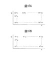
さて、本発明による実施例では、炭化水素供給弁15からの炭化水素噴射量および噴射時期を変化させることによって炭化水素濃度の振幅ΔHおよび振動周期ΔTが機関の運転状態に応じた最適値となるように制御される。この場合、本発明による実施例では、高圧排気ガス再循環装置HPLによる排気ガス再循環作用を行ないつつ第1のNOx浄化方法によるNOx浄化作用が行われているときの最適な炭化水素噴射量WTが燃料噴射弁3からの噴射量Qおよび機関回転数Nの関数として図17Aに示すようなマップの形で予めROM32内に記憶されており、また、このときの最適な炭化水素の噴射周期ΔTも燃料噴射弁3からの噴射量Qおよび機関回転数Nの関数として図17Bに示すようなマップの形で予めROM32内に記憶されている。同様に、低圧排気ガス再循環装置LPLによる排気ガス再循環作用を行いつつ第1のNOx浄化方法によるNOx浄化作用が行われているときの最適な炭化水素噴射量WTおよび噴射周期ΔTも燃料噴射弁3からの噴射量Qおよび機関回転数Nの関数として夫々予めROM32内に記憶されている。
In the embodiment according to the present invention, the hydrocarbon concentration amplitude ΔH and the vibration period ΔT become optimum values according to the operating state of the engine by changing the hydrocarbon injection amount and injection timing from the hydrocarbon supply valve 15. To be controlled. In this case, in the embodiment according to the present invention, the optimum hydrocarbon injection amount WT when the NOx purification action by the first NOx purification method is performed while the exhaust gas recirculation action is performed by the high pressure exhaust gas recirculation system HPL. Is stored in advance in the
次に図18から図21を参照しつつ排気浄化触媒13をNOx吸蔵触媒として機能させた場合のNOx浄化方法について具体的に説明する。このように排気浄化触媒13をNOx吸蔵触媒として機能させた場合のNOx浄化方法を以下、第2のNOx浄化方法と称する。Next, the NO x purification method when the
この第2のNOx浄化方法では図18に示されるように塩基性層53に吸蔵された吸蔵NOx量ΣNOXが予め定められた許容量MAXを越えたときに排気浄化触媒13に流入する排気ガスの空燃比(A/F)inが一時的にリッチにされる。排気ガスの空燃比(A/F)inがリッチにされると、排気ガスの空燃比(A/F)inがリーンのときに塩基性層53内に吸蔵されたNOxが塩基性層53から一気に放出されて還元される。それによってNOxが浄化される。In this second NO x purification method, as shown in FIG. 18, the exhaust gas flowing into the
吸蔵NOx量ΣNOXは例えば機関から排出されるNOx量から算出される。本発明による実施例では機関から単位時間当り排出される排出NOx量NOXAが噴射量Qおよび機関回転数Nの関数として図19に示すようなマップの形で予めROM32内に記憶されており、この排出NOx量NOXAから吸蔵NOx量ΣNOXが算出される。この場合、前述したように排気ガスの空燃比(A/F)inがリッチにされる周期は通常1分以上である。Occluded amount of NO x ΣNOX is calculated from the amount of NO x exhausted from the engine, for example. In the embodiment according to the present invention is stored in advance in the ROM32 in the form of a map as discharge amount of NO x NOXA exhausted from the engine per unit time is shown in FIG. 19 as a function of the injection quantity Q and engine speed N, The occluded NO x amount ΣNOX is calculated from this exhausted NO x amount NOXA. In this case, as described above, the period during which the air-fuel ratio (A / F) in of the exhaust gas is made rich is usually 1 minute or more.
この第2のNOx浄化方法では図20に示されるように燃焼室2内に燃料噴射弁3から燃焼用燃料Qに加え、追加の燃料WRを噴射することによって排気浄化触媒13に流入する排気ガスの空燃比(A/F)inがリッチにされる。なお、図20の横軸はクランク角を示している。この追加の燃料WRは燃焼はするが機関出力となって現われない時期に、即ち圧縮上死点後ATDC90°の少し手前で噴射される。この燃料量WRは噴射量Qおよび機関回転数Nの関数として図21に示すようなマップの形で予めROM32内に記憶されている。無論、この場合炭化水素供給弁15からの炭化水素の噴射量を増大させることによって排気ガスの空燃比(A/F)inをリッチにすることもできる。In this second NO x purification method, as shown in FIG. 20, the exhaust gas flowing into the
さて、排気浄化触媒13から排気管14内に流出する排気ガスの温度は排気マニホルド5内に排出される排気ガスの温度に比べてかなり低く、従って低圧排気ガス再循環装置LPLにより燃焼室2内に再循環される排気ガスの温度は高圧排気ガス再循環装置HPLにより燃焼室2内に再循環される排気ガスの温度に比べてかなり低くなる。従って低圧排気ガス再循環装置LPLにより排気ガスを再循環した場合の方が、高圧排気ガス再循環装置HPLにより排気ガスを再循環した場合に比べて燃焼室2内における燃焼温が低下し、燃焼室2内におけるNOxの生成量が低下する。即ち、低圧排気ガス再循環装置LPLを用いて排気ガスを再循環した場合の方が、高圧排気ガス再循環装置HPLを用いて排気ガスを再循環した場合に比べて燃焼室2から排出されるNOxの量を低下させることができる。
Now, the temperature of the exhaust gas flowing out from the
従って、本発明による実施例では通常、低圧排気ガス再循環装置LPLを用いて排気ガスの再循環作用が行われ、低圧排気ガス再循環装置LPLを用いるよりも高圧排気ガス再循環装置HPLを用いた方が好ましい場合に限って、高圧排気ガス再循環装置HPLが用いられる。 Therefore, in the embodiment according to the present invention, the exhaust gas recirculation operation is normally performed using the low pressure exhaust gas recirculation device LPL, and the high pressure exhaust gas recirculation device HPL is used rather than the low pressure exhaust gas recirculation device LPL. The high-pressure exhaust gas recirculation system HPL is used only when it is preferable.
一方、第1のNOx浄化方法を用いたときのNOx浄化率と第2のNOx浄化方法を用いたときのNOx浄化率とを比べると第1のNOx浄化方法を用いた場合の方が高いNOx浄化率を得ることができる。一方、第1のNOx浄化方法を用いた場合の炭化水素の供給頻度は第2のNOx浄化方法を用いた場合の炭化水素の供給頻度よりもかなり高いので、NOxを浄化するために消費される炭化水素量は、第1のNOx浄化方法を用いた場合の方が第2のNOx浄化方法を用いた場合に比べて多くなる。即ち、NOx浄化率からみると、第1のNOx浄化方法を用いることが好ましいが、炭化水素消費量の低減という観点からみると、第2のNOx浄化方法を用いることが好ましいと言える。 On the other hand, comparing the NOx purification rate when using the first NOx purification method with the NOx purification rate when using the second NOx purification method, NOx is higher when the first NOx purification method is used. A purification rate can be obtained. On the other hand, the hydrocarbon supply frequency when the first NOx purification method is used is considerably higher than the hydrocarbon supply frequency when the second NOx purification method is used, and is consumed for purifying NOx. The amount of hydrocarbons is greater when the first NOx purification method is used than when the second NOx purification method is used. That is, from the viewpoint of NOx purification rate, it is preferable to use the first NOx purification method, but from the viewpoint of reducing hydrocarbon consumption, it can be said that the second NOx purification method is preferably used.
これらのことを考慮して、低圧排気ガス再循環装置LPLを用いるか或いは高圧排気ガス再循環装置HPLを用いるかが、および第1のNOx浄化方法を用いるか或いは第2のNOx浄化方法を用いるかが決定される。本発明による実施例では、図22に示されるように、燃料噴射弁3からの燃料噴射量Qおよび機関回転数Nに応じて機関の運転領域が三つの運転領域I,IIおよびIIIに分けられており、定常運転時には低圧排気ガス再循環装置LPLと高圧排気ガス再循環装置HPLとのいずれを用いるかが、および第1のNOx浄化方法と第2のNOx浄化方法のいずれを用いるかが各運転領域I,IIおよびIIIについて夫々予め定められている。
Considering these things, whether to use the low pressure exhaust gas recirculation device LPL or the high pressure exhaust gas recirculation device HPL, use the first NOx purification method, or use the second NOx purification method. Is determined. In the embodiment according to the present invention, as shown in FIG. 22, the operating range of the engine is divided into three operating ranges I, II and III according to the fuel injection amount Q from the
図22において、運転領域IIは、定常運転時に最も頻繁に使用される中速中負荷運転領域を表しており、定常運転時にはこの運転領域IIでは、排気ガス再循環装置としては低圧排気ガス再循環装置LPLが用いられており、NOx浄化方法としては第2のNOx浄化方法が用いられている。即ち、運転領域IIでは、燃焼室2からのNOxの排出量を低減させるべく低圧排気ガス再循環装置LPLが用いられ、炭化水素消費量を低減すべく第2のNOx浄化方法が用いられる。
In FIG. 22, the operation region II represents a medium-speed and medium-load operation region that is most frequently used during normal operation, and in this operation region II during normal operation, low-pressure exhaust gas recirculation is used as the exhaust gas recirculation device. The apparatus LPL is used, and the second NOx purification method is used as the NOx purification method. That is, in the operation region II, the low-pressure exhaust gas recirculation device LPL is used to reduce the NOx emission amount from the
一方、図22において、運転領域IIIは、高速高負荷運転領域を表しており、定常運転時にはこの運転領域IIIでは、排気ガス再循環装置として低圧排気ガス再循環装置LPLが用いられており、NOx浄化方法として第1のNOx浄化方法が用いられている。即ち、高速高負荷運転時には、燃焼室2からのNOxの排出量が増大し、従ってこのときには燃焼室2からのNOxの排出量をできる限り低減させるべく低圧排気ガス再循環装置LPLが用いられ、高いNOx浄化率が得られるように第1のNOx浄化方法が用いられる。なおこの運転領域IIIでは、定常運転時に限らず、加速運転時のような過渡運転時でも、排気ガス再循環装置として低圧排気ガス再循環装置LPLが用いられ、NOx浄化方法として第1のNOx浄化方法が用いられる。
On the other hand, in FIG. 22, the operation region III represents a high-speed and high-load operation region. During steady operation, in this operation region III, the low-pressure exhaust gas recirculation device LPL is used as the exhaust gas recirculation device. The first NOx purification method is used as the purification method. That is, during high-speed and high-load operation, the amount of NOx discharged from the
一方、図22において、運転領域Iは、低速低負荷運転領域を表しており、定常運転時にはこの運転領域Iでは、排気ガス再循環装置として高圧排気ガス再循環装置HPLが用いられており、NOx浄化方法としては第2のNOx浄化方法が用いられている。即ち、低速低負荷運転時には、燃焼室2から排出される排気ガスの温度が低く、このとき低圧排気ガス再循環装置LPLを用いて排気ガスを再循環させると排気ガス中に含まれる水分が冷却装置25内において凝縮し、その結果低圧排気ガス再循環装置LPL内に水分が蓄積してしまうという問題を生ずる。このような問題が生じないようにするために運転領域Iでは、高圧排気ガス再循環装置HPLが用いられ、炭化水素消費量を低減すべく第2のNOx浄化方法が用いられる。
On the other hand, in FIG. 22, an operation region I represents a low-speed and low-load operation region, and during normal operation, the high-pressure exhaust gas recirculation device HPL is used as the exhaust gas recirculation device in this operation region I. As the purification method, the second NOx purification method is used. That is, during low-speed and low-load operation, the temperature of the exhaust gas discharged from the
このように図22に示される実施例では、定常運転時には運転領域IIおよびIIIでは低圧排気ガス再循環装置LPLが用いられ、運転領域Iにおいてのみ高圧排気ガス再循環装置HPLが用いられる。一方、定常運転時には運転領域IおよびIIでは第2のNOx浄化方法が用いられ、運転領域IIIでは第1のNOx浄化方法が用いられる。即ち、本発明による実施例では、機関低速低負荷側では第2のNOx浄化方法によるNOx浄化作用が行われ、機関高速高負荷側では第1のNOx浄化方法によるNOx浄化作用が行われる。 In this way, in the embodiment shown in FIG. 22, the low pressure exhaust gas recirculation device LPL is used in the operation regions II and III during steady operation, and the high pressure exhaust gas recirculation device HPL is used only in the operation region I. On the other hand, during steady operation, the second NOx purification method is used in the operation regions I and II, and the first NOx purification method is used in the operation region III. That is, in the embodiment according to the present invention, the NOx purification action by the second NOx purification method is performed on the engine low speed and low load side, and the NOx purification action by the first NOx purification method is performed on the engine high speed and high load side.
次に、機関の運転状態が運転領域I又はIIにあるときに、加速運転が行われた場合について説明する。図22には、機関の運転状態が運転領域Iのa点にあるときに加速運転が行われた場合の運転状態の変化と、機関の運転状態が運転領域IIのb点にあるときに加速運転が行われた場合の運転状態の変化とが矢印で示されている。なお、図22において破線の矢印は、加速運転が行われたときに加速の度合いが予め定められた度合い以下のときの、即ち緩加速運転が行われたときの運転状態の変化を示している。このように加速の度合いが予め定められた度合い以下の緩加速運転が行われたときには、排気ガス再循環装置およびNOx浄化方法は各運転領域I,IIおよびIIIに対して予め定められている排気ガス再循環装置およびNOx浄化方法が用いられる。例えば機関の運転状態が運転領域Iのa点にあるときに緩加速運転が行われたときには、機関の運転状態が運転領域IとIIの境界Xを越えたときに第2のNOx浄化方法によるNOx浄化作用を維持しつつ高圧排気ガス再循環装置HPLによる排気ガスの再循環作用から低圧排気ガス再循環装置LPL による排気ガスの再循環作用に切替えられ、機関の運転状態が運転領域IIとIIIの境界Yを越えたときに低圧排気ガス再循環装置LPLによる排気ガスの再循環作用を維持しつつ第2のNOx浄化方法によるNOx浄化作用から第1のNOx浄化方法によるNOx浄化作用に切替えられる。 Next, the case where the acceleration operation is performed when the operation state of the engine is in the operation region I or II will be described. FIG. 22 shows changes in the operating state when the acceleration operation is performed when the engine operating state is at point a in the operating region I, and acceleration when the engine operating state is at point b in the operating region II. The change of the operation state when the operation is performed is indicated by an arrow. In FIG. 22, the broken line arrows indicate the change in the driving state when the acceleration degree is equal to or less than a predetermined degree when the acceleration operation is performed, that is, when the slow acceleration operation is performed. . Thus, when the slow acceleration operation is performed with the degree of acceleration equal to or less than a predetermined degree, the exhaust gas recirculation device and the NOx purification method are exhausted in advance for each operation region I, II, and III. A gas recirculation device and NOx purification method are used. For example, when the slow acceleration operation is performed when the operating state of the engine is at point a in the operating region I, the second NOx purification method is used when the operating state of the engine exceeds the boundary X between the operating regions I and II. While maintaining the NOx purification action, the exhaust gas recirculation action by the high pressure exhaust gas recirculation equipment HPL is switched to the exhaust gas recirculation action by the low pressure exhaust gas recirculation equipment LPL. The NOx purification action by the second NOx purification method is switched to the NOx purification action by the first NOx purification method while maintaining the exhaust gas recirculation action by the low-pressure exhaust gas recirculation device LPL when the boundary Y of the exhaust gas is exceeded. .
これに対し、機関の運転状態が運転領域I又はIIにあるときに加速運転が行われ、このとき加速の度合いが予め定められた度合い以上であるとき、即ち図22において実線の矢印で示されるように急加速運転が行われたときには、上述の緩加速運転時とは異なる制御が行われる。即ち、機関負荷が急速に高められて急加速運転が行われると燃焼室2内で生成されるNOx量が急激に増大する。従ってこのとき燃焼室2から排出されるNOx量を低減するには再循環排気ガス量を急速に増大する必要がある。しかしながらこのとき、低圧排気ガス再循環装置LPLを用いて再循環作用が行われているとすると、再循環排気ガス量を急速に増大すべくEGR制御弁24の開度を大きくしても排気管14から燃焼室2に至るまでの通路容積が大きいために、燃焼室2内に供給される再循環排気ガス量を急速に増大することはできない。従って、急加速運転が行われたときに低圧排気ガス再循環装置LPLによる排気ガスの再循環が行われていると、急加速運転が行われたときに多量のNOxが排出されるという問題を生ずる。
On the other hand, acceleration operation is performed when the engine operating state is in the operation region I or II, and at this time, when the degree of acceleration is greater than or equal to a predetermined degree, that is, indicated by a solid arrow in FIG. Thus, when the rapid acceleration operation is performed, control different from that in the above-described slow acceleration operation is performed. That is, when the engine load is rapidly increased and the rapid acceleration operation is performed, the amount of NOx generated in the
これに対し、高圧排気ガス再循環装置HPLでは排気マニホルド5から燃焼室2に至るまでの通路容積が小さいために、EGR制御弁24の開度を大きくすれば燃焼室2内に供給される再循環排気ガス量はただちに増大する。従って本発明では、低圧排気ガス再循環装置LPLによる排気ガスの再循環が行われているときに、急加速運転が行われたときには低圧排気ガス再循環装置LPLによる排気ガスの再循環作用から高圧排気ガス再循環装置HPLによる排気ガスの再循環作用にただちに切替えるようにしている。一方、急加速運転が行われて機関負荷が高くなると燃焼室2からのNOxの排出量が増大し、またこのとき低圧排気ガス再循環装置LPLによる排気ガスの再循環作用から高圧排気ガス再循環装置HPLによる排気ガスの再循環作用に切替えられると燃焼室2からのNOxの排出量が更に増大する。従ってこのときには、NOxを良好に浄化するために、第2のNOx浄化方法によるNOx浄化作用から第1のNOx浄化方法によるNOx浄化作用にただちに切替えられる。
In contrast, in the high-pressure exhaust gas recirculation system HPL, the passage volume from the
従って本発明によれば、コンプレッサ7aと排気タービン7bを有する排気ターボチャージャ7を具備しており、排気タービン7b下流の機関排気通路内に排気浄化触媒13を配置すると共に排気浄化触媒13上流の機関排気通路内に炭化水素供給弁15を配置し、排気浄化触媒13の排気ガス流通表面上には貴金属触媒51,52が担持されていると共に貴金属触媒51,52周りには塩基性の排気ガス流通表面部分54が形成されており、排気浄化触媒13は、排気浄化触媒13に流入する炭化水素の濃度を予め定められた範囲内の振幅および予め定められた範囲内の周期でもって振動させると排気ガス中に含まれるNOxを還元する性質を有すると共に、炭化水素濃度の振動周期を予め定められた範囲よりも長くすると排気ガス中に含まれるNOxの吸蔵量が増大する性質を有しており、排気浄化触媒13に流入する炭化水素の濃度を予め定められた範囲内の振幅および周期でもって振動させることによりNOxを浄化する第1のNOx浄化方法と、炭化水素濃度の振動周期を予め定められた範囲よりも長くすることによりNOxを排気浄化触媒13に吸蔵させると共に排気ガスの空燃比をリッチにすることによって吸蔵されたNOxを放出させる第2のNOx浄化方法とを選択的に用いることのできる内燃機関の排気浄化装置において、排気タービン7b上流の機関排気通路内の比較的高圧の排気ガスをコンプレッサ7a下流の吸気通路内に再循環させる高圧排気ガス再循環装置HPLと、排気浄化触媒13下流の機関排気通路内の比較的低圧の排気ガスをコンプレッサ7a上流の吸気通路内に再循環させる低圧排気ガス再循環装置LPLとを具備しており、低圧排気ガス再循環装置LPLによる排気ガス再循環作用を行いつつ第2のNOx浄化方法によるNOx浄化作用が行われているときに、加速の度合いが予め定められた度合い以上の加速運転が行われたときには、NOx浄化作用が第1のNOx浄化方法によるNOx浄化作用に切替えられると共に排気ガス再循環作用が一時的に高圧排気ガス再循環装置HPLによる排気ガス再循環作用に切替えられる。Therefore, according to the present invention, the
なお、この場合、加速運転時における加速の度合いが予め定められた度合い以下のときには、即ち緩加速運転時には排気ガス再循環作用が低圧排気ガス再循環装置LPLによる排気ガス再循環作用のまま維持される。 Incidentally, maintaining this case, when the degree of acceleration during acceleration operation degree below a predetermined, that slow acceleration during continuous running of the exhaust gas recirculation action recirculation effect exhaust gas by low pressure exhaust gas recirculation system LPL Is done.
図23は、図22において機関の運転状態が運転領域Iのa点にあるときに加速運転が行われた場合のアクセルペダル40の踏込み量の変化と、高圧排気ガス再循環装置HPLのEGR制御弁17の開度の変化と、低圧排気ガス再循環装置LPLのEGR制御弁24の開度の変化と、NOx浄化方法とが示されている。なお、図23における破線は、図22において破線の矢印で示されるように加速の度合いが予め定められた度合い以下であるとき、即ち緩加速運転が行われたときを示しており、図23における実線は、図22において実線の矢印で示されるように加速の度合いが予め定められた度合い以上であるとき、即ち急加速運転が行われたときを示している。
FIG. 23 shows the change in the amount of depression of the
機関の運転状態が運転領域Iにあるときには前述したように、高圧排気ガス再循環装置HPLによる排気ガス再循環作用を行いつつ第2のNOx浄化方法によるNOx浄化作用が行われている。このときには図23からわかるように、低圧排気ガス再循環装置LPLのEGR制御弁24は全閉せしめられており、高圧排気ガス再循環装置HPLのEGR制御弁17の開度は機関の運転状態から定まる開度とされている。次いで、破線の矢印で示されるように、アクセルペダル40がゆっくりと踏み込まれたとすると、即ち緩加速運転が行われたとすると、機関の運転状態が図22に示される境界Xを越えたときに破線の矢印で示される如く、第2のNOx浄化方法によるNOx浄化作用を維持しつつ排気ガス再循環作用が高圧排気ガス再循環装置HPLによる排気ガス再循環作用から低圧排気ガス再循環装置LPLによる排気ガス再循環作用に切替られる。次いで機関の運転状態が図22に示される境界Yを越えると低圧排気ガス再循環装置LPLによる排気ガス再循環作用を維持しつつNOx浄化作用が第2のNOx浄化方法によるNOx浄化作用から第1のNOx浄化方法によるNOx浄化作用に切替えられる。
When the operating state of the engine is in the operating region I, as described above, the NOx purification action by the second NOx purification method is performed while the exhaust gas recirculation action is performed by the high pressure exhaust gas recirculation system HPL. At this time, as can be seen from FIG. 23, the
これに対し、機関の運転状態が運転領域Iにあるときに、図23において実線の矢印で示されるように、アクセルペダル40が急速に踏み込まれたとすると、即ち急加速運転が行われたとすると、NOx浄化作用が第2のNOx浄化方法によるNOx浄化作用から第1のNOx浄化方法によるNOx浄化作用にただちに切替えられる。一方、このとき排気ガス再循環作用は、予め定められている時間th,高圧排気ガス再循環装置HPLによる排気ガス再循環作用のまま維持され、この予め定められた時間thを経過すると、排気ガス再循環作用が低圧排気ガス再循環装置LPLによる排気ガス再循環作用に徐々に切替られる。
On the other hand, when the operation state of the engine is in the operation region I, as shown by the solid line arrow in FIG. 23, if the
即ち、高圧排気ガス再循環装置HPLによる排気ガス再循環作用を行いつつ第2のNOx浄化方法によるNOx浄化作用が行われているときに、加速の度合いが予め定められた度合い以上の加速運転が行われたときには、NOx浄化作用が第1のNOx浄化方法によるNOx浄化作用に切替えられると共に排気ガス再循環作用は高圧排気ガス再循環装置HPLによる排気ガス再循環作用のまま予め定められた期間維持された後に低圧排気ガス再循環装置LPLによる排気ガス再循環作用に徐々に切替えられる。なお、図23において実線の矢印で示されるように、加速運転が開始されたときから、高圧排気ガス再循環装置HPLによる排気ガス再循環作用が停止され、低圧排気ガス再循環装置LPLのみによる排気ガス再循環作用が開始されるまでの処理を、加速開始処理と称する。 That is, when the NOx purification action by the second NOx purification method is being performed while the exhaust gas recirculation action by the high-pressure exhaust gas recirculation system HPL is being performed, the acceleration operation exceeds the predetermined degree. When performed, the NOx purification action is switched to the NOx purification action by the first NOx purification method, and the exhaust gas recirculation action is maintained for a predetermined period while maintaining the exhaust gas recirculation action by the high pressure exhaust gas recirculation device HPL. Then, the operation is gradually switched to the exhaust gas recirculation action by the low pressure exhaust gas recirculation device LPL. Note that, as indicated by the solid line arrow in FIG. 23, the exhaust gas recirculation action by the high pressure exhaust gas recirculation device HPL is stopped after the acceleration operation is started, and the exhaust by only the low pressure exhaust gas recirculation device LPL. A process until the gas recirculation action is started is referred to as an acceleration start process.
図24は、図22において機関の運転状態が運転領域IIのb点にあるときに加速運転が行われた場合のアクセルペダル40の踏込み量の変化と、高圧排気ガス再循環装置HPLのEGR制御弁17の開度の変化と、低圧排気ガス再循環装置LPLのEGR制御弁24の開度の変化と、NOx浄化方法とが示されている。なお、図23と同様に、図24における破線は、図22において破線の矢印で示されるように加速の度合いが予め定められた度合い以下であるとき、即ち緩加速運転が行われたときを示しており、図24における実線は、図22において実線の矢印で示されるように加速の度合いが予め定められた度合い以上であるとき、即ち急加速運転が行われたときを示している。
FIG. 24 shows the change in the amount of depression of the
機関の運転状態が運転領域IIにあるときには前述したように、低圧排気ガス再循環装置LPLによる排気ガス再循環作用を行いつつ第2のNOx浄化方法によるNOx浄化作用が行われている。このときには図24からわかるように、高圧排気ガス再循環装置HPLのEGR制御弁17は全閉せしめられており、低圧排気ガス再循環装置LPLのEGR制御弁24の開度は機関の運転状態から定まる開度とされている。次いで、破線の矢印で示されるように、アクセルペダル40がゆっくりと踏み込まれたとすると、即ち緩加速運転が行われたとすると、機関の運転状態が図22に示される境界Yを越えたときに低圧排気ガス再循環装置LPLによる排気ガス再循環作用を維持しつつNOx浄化作用が第2のNOx浄化方法によるNOx浄化作用から第1のNOx浄化方法によるNOx浄化作用に切替えられる。
When the operating state of the engine is in the operation region II, as described above, the NOx purification action by the second NOx purification method is performed while the exhaust gas recirculation action is performed by the low pressure exhaust gas recirculation device LPL. At this time, as can be seen from FIG. 24, the
これに対し、機関の運転状態が運転領域IIにあるときに、図24において実線の矢印で示されるように、アクセルペダル40が急速に踏み込まれたとすると、即ち急加速運転が行われたとすると、NOx浄化作用が第2のNOx浄化方法によるNOx浄化作用から第1のNOx浄化方法によるNOx浄化作用にただちに切替えられる。一方、このとき排気ガス再循環作用は、低圧排気ガス再循環装置LPLによる排気ガス再循環作用から高圧排気ガス再循環装置HPLによる排気ガス再循環作用にただちに切替えられ、次いで予め定められている時間th,高圧排気ガス再循環装置HPLによる排気ガス再循環作用に維持され、次いでこの予め定められた時間thを経過すると、排気ガス再循環作用が低圧排気ガス再循環装置LPLによる排気ガス再循環作用に徐々に切替られる。なお、この場合には、図24において実線の矢印で示されるように、低圧排気ガス再循環装置LPLによる排気ガス再循環作用から高圧排気ガス再循環装置HPLによる排気ガス再循環作用に切替えられたときから、高圧排気ガス再循環装置HPLによる排気ガス再循環作用が再び停止され、低圧排気ガス再循環装置LPLのみによる排気ガス再循環作用が開始されるまでの処理が、加速開始処理と称される。
On the other hand, when the operation state of the engine is in the operation region II, as shown by the solid line arrow in FIG. 24, if the
即ち、前述したように、低圧排気ガス再循環装置LPLによる排気ガス再循環作用を行いつつ第2のNOx浄化方法によるNOx浄化作用が行われているときに、加速の度合いが予め定められた度合い以上の加速運転が行われたときには、NOx浄化作用が第1のNOx浄化方法によるNOx浄化作用に切替えられると共に排気ガス再循環作用が一時的に高圧排気ガス再循環装置HPLによる排気ガス再循環作用に切替えられる。 That is, as described above, when the NOx purification action by the second NOx purification method is performed while the exhaust gas recirculation action is performed by the low pressure exhaust gas recirculation device LPL, the degree of acceleration is determined in advance. When the above acceleration operation is performed, the NOx purification action is switched to the NOx purification action by the first NOx purification method and the exhaust gas recirculation action is temporarily changed to the exhaust gas recirculation action by the high pressure exhaust gas recirculation device HPL. Is switched to.
図24において予め定められた時間th、即ち排気ガス再循環作用が一時的に高圧排気ガス再循環装置HPLによる排気ガス再循環作用に切替えられている時間thは、排気ガス再循環作用を低圧排気ガス再循環装置LPLによる排気ガス再循環作用に切替えても十分な量の排気ガスを燃焼室2内に再循環し得るようになるまでの時間である。この時間thは図25に示されるように加速の度合いが高くなるほど長くされる。このことは図23に示される場合も同様であって、急加速運転が開始された後、高圧排気ガス再循環装置HPLによる排気ガス再循環作用に維持されている時間thも図25に示されるように加速の度合いが高くなるほど長くされる。
In FIG. 24, the predetermined time th, that is, the time th when the exhaust gas recirculation action is temporarily switched to the exhaust gas recirculation action by the high pressure exhaust gas recirculation system HPL, This is the time until a sufficient amount of exhaust gas can be recirculated into the
図26には、第2のNOx浄化方法によるNOx浄化作用から第1のNOx浄化方法によるNOx浄化作用に切替えられるときの、追加の燃料WRの噴射時期と、炭化水素WTの供給タイミングと、排気浄化触媒13に流入する排気ガスの空燃比(A/F)inの変化と、排気浄化触媒13に吸蔵される吸蔵NOx量ΣNOXとが示されている。排気浄化触媒13にNOxが吸蔵されている状態で、第2のNOx浄化方法によるNOx浄化作用から第1のNOx浄化方法によるNOx浄化作用に切替えられると、第1のNOx浄化方法によるNOx浄化作用が開始されたときに、排気浄化触媒13に吸蔵されているNOxが還元されることなく放出される。そこで本発明による実施例では、第2のNOx浄化方法によるNOx浄化作用から第1のNOx浄化方法によるNOx浄化作用に切替えられるときに排気浄化触媒13にNOxが吸蔵されているときには、吸蔵されているNOxを放出させ還元させるために、図26に示されるように追加の燃料WRが供給され、排気浄化触媒13に流入する排気ガスの空燃比(A/F)inが一時的にリッチにされる。FIG. 26 shows the injection timing of the additional fuel WR, the supply timing of the hydrocarbon WT, the exhaust gas when the NOx purification action by the second NOx purification method is switched to the NOx purification action by the first NOx purification method. A change in the air-fuel ratio (A / F) in of the exhaust gas flowing into the
図27および図28にNOx浄化制御ルーチンを示す。このルーチンは一定時間毎の割込みによって実行される。27 and 28 show the NO x purification control routine. This routine is executed by interruption every predetermined time.
図27を参照するとまず初めにステップ60において、加速運転時における加速の度合いΔDが検出される。この加速の度合いΔDは、例えばアクセルペダル40の踏込み量の単位時間当りの変化に基づいて算出される。次いでステップ61では、加速の度合いΔDが予め定められている度合いDXよりも大きいか否かが、即ち急加速運転時であるか否かが判別される。加速の度合いΔDが予め定められている度合いDXよりも小さいとき、即ち緩加速運転時にはステップ62に進んで、機関の運転状態が図22に示される運転領域Iであるか否かが判別される。機関の運転状態が運転領域Iであるときにはステップ63に進んで高圧排気ガス再循環装置HPLによる排気ガス再循環作用が行われる。次いでステップ64に進んで第2のNOx浄化方法によるNOx浄化作用が行われる。Referring to FIG. 27, first, at
即ち、ステップ64では図17に示すマップから単位時間当りの排出NOx量NOXAが算出される。次いでステップ65ではΣNOXに排出NOx量NOXAを加算することによって吸蔵NOx量ΣNOXが算出される。次いでステップ66では吸蔵NOx量ΣNOXが許容値MAXを越えたか否かが判別される。ΣNOX>MAXになるとステップ67に進んで図21に示すマップから追加の燃料量WRが算出され、追加の燃料の噴射作用が行われる。次いでステップ68ではΣNOXがクリアされる。That is, the discharge amount of NO x NOXA per unit time is calculated from the map shown in FIG. 17 at
一方、ステップ62において機関の運転状態が運転領域Iでないと判別されたときにはステップ69に進んで低圧排気ガス再循環装置LPLによる排気ガス再循環作用が行われる。次いでステップ70では機関の運転状態が図22に示される運転領域IIであるか否かが判別される。機関の運転状態が運転領域IIであるときにはステップ64に進んで第2のNOx浄化方法によるNOx浄化作用が行われる。これに対し、機関の運転状態が運転領域IIでないとき、即ち機関の運転状態が図22に示される運転領域IIIであるときにはステップ71に進んで機関の運転状態が今、運転領域IIから運転領域IIIに変化したか否かが判別される。機関の運転状態が今、運転領域IIから運転領域IIIに変化していないとき、即ち機関の運転状態が継続して運転領域IIIであるときにはステップ74にジャンプして第1のNOx浄化方法によるNOx浄化作用が行われる。即ち、図17Aに示されるマップから運転状態に応じた噴射時間WTが算出され、図17Bに示されるマップから運転状態に応じた噴射周期ΔTが算出され、これら算出された噴射時間WTおよび噴射周期ΔTに従って炭化水素供給弁15から炭化水素が噴射される。On the other hand, when it is determined in
一方、ステップ71において機関の運転状態が今、運転領域IIから運転領域IIIに変化したと判断されたときにはステップ72に進んで、吸蔵NOx量ΣNOXが一定値MINよりも大きいか否かが判別される。なお、この一定値MINは許容値MAXよりもかなり小さな値とされている。ステップ72において吸蔵NOx量ΣNOXが一定値MINよりも小さいと判断されたときにはステップ74にジャンプして第1のNOx浄化方法によるNOx浄化作用が行われる。これに対し吸蔵NOx量ΣNOXが一定値MINよりも大きいと判断されたときにはステップ73に進み、吸蔵されているNOxを放出させ還元させるために、図26に示されるように追加の燃料WRが供給されて排気浄化触媒13に流入する排気ガスの空燃比(A/F)inが一時的にリッチにされ、ΣNOXがクリアされる。次いでステップ74に進み、第1のNOx浄化方法によるNOx浄化作用が開始される。On the other hand, when it is determined in
一方、ステップ61において加速の度合いΔDが予め定められている度合いDXよりも大きいと判別されたとき、即ち急加速運転時にはステップ75に進んで機関の運転状態が運転領域IIIであるか否かが判別される。機関の運転状態が運転領域IIIであるときにはステップ76に進んで低圧排気ガス再循環装置LPLによる排気ガス再循環作用が行われ、次いでステップ74に進んで第1のNOx浄化方法によるNOx浄化作用が行われる。即ち、機関の運転状態が運転領域IIIであるときに急加速運転が行われたときには、継続して低圧排気ガス再循環装置LPLによる排気ガス再循環作用を行いつつ第1のNOx浄化方法によるNOx浄化作用が行われる。
On the other hand, when it is determined in
これに対し、ステップ75において機関の運転状態が運転領域IIIでないと判別されたとき、即ち機関の運転状態が運転領域I又はIIであるときに急加速運転が行われたときには図28のステップ77に進んで、前述した加速開始処理が完了したか否かが判別される。加速開始処理が完了していないときにはステップ78に進んで加速開始時であるか否かが判別される。加速開始時であるときにはステップ79に進み、吸蔵NOx量ΣNOXが一定値MINよりも大きいか否かが判別される。吸蔵NOx量ΣNOXが一定値MINよりも小さいと判断されたときにはステップ81にジャンプする。これに対し吸蔵NOx量ΣNOXが一定値MINよりも大きいときにはステップ80に進み、吸蔵されているNOxを放出させ還元させるために、図26に示されるように追加の燃料WRが供給されて排気浄化触媒13に流入する排気ガスの空燃比(A/F)inが一時的にリッチにされ、ΣNOXがクリアされる。次いでステップ81に進む。On the other hand, when it is determined in
ステップ81では加速の度合いΔDに基づいて図25に示される関係から時間thが算出される。次いでステップ82では加速開始時における機関の運転状態が運転領域Iであったか否かが判別される。加速開始時における機関の運転状態が運転領域Iであったときにはステップ83に進んで、低圧排気ガス再循環装置LPLのEGR制御弁24の開度を図23の実線の矢印で示すように変化せしめるEGR制御弁作動指令が発せられる。次いでステップ84に進んで、高圧排気ガス再循環装置HPLのEGR制御弁17の開度を図23の実線の矢印で示すように変化せしめるEGR制御弁作動指令が発せられる。即ち、低圧排気ガス再循環装置LPLのEGR制御弁24の開度および高圧排気ガス再循環装置HPLのEGR制御弁17の開度を図23の実線の矢印で示すように変化させる加速開始処理を行うべき指令が発せられる。
In
一方、ステップ82において、加速開始時における機関の運転状態が運転領域IIであると判断されときにはステップ85に進んで、低圧排気ガス再循環装置LPLのEGR制御弁24の開度を図24の実線の矢印で示すように変化せしめるEGR制御弁作動指令が発せられる。次いでステップ86に進んで、高圧排気ガス再循環装置HPLのEGR制御弁17の開度を図24の実線の矢印で示すように変化せしめるEGR制御弁作動指令が発せられる。即ち、低圧排気ガス再循環装置LPLのEGR制御弁24の開度および高圧排気ガス再循環装置HPLのEGR制御弁17の開度を図24の実線の矢印で示すように変化させる加速開始処理を行うべき指令が発せられる。
On the other hand, when it is determined in
一方、ステップ75において加速開始時ではないと判断されたとき、即ち加速運転中であると判断されたときには、ステップ87に進んで第1のNOx浄化方法によるNOx浄化作用が行われる。即ち、加速運転が開始されると、吸蔵NOx量ΣNOXが一定値MINよりも大きい場合には排気浄化触媒13に吸蔵されているNOxを放出させ還元させるために排気浄化触媒13に流入する排気ガスの空燃比(A/F)inが一時的にリッチにされ、次いで第2のNOx浄化方法によるNOx浄化作用から第1のNOx浄化方法によるNOx浄化作用に切替えられる。次いでステップ77において、ステップ83および84又はステップ85および86において発せられた作動命令が完了したと判断されると、即ち、加速開始処理が完了するとステップ88に進んで低圧排気ガス再循環装置LPL による排気ガス再循環作用が行われる。次いでステップ87に進む。On the other hand, when it is determined at
なお、別の実施例として排気浄化触媒13上流の機関排気通路内に炭化水素を改質させるための酸化触媒を配置することもできる。
As another embodiment, an oxidation catalyst for reforming hydrocarbons may be disposed in the engine exhaust passage upstream of the
4 吸気マニホルド
5 排気マニホルド
7 排気ターボチャージャ
12 排気管
13 排気浄化触媒
15 炭化水素供給弁
HPL 高圧排気ガス再循環装置
LPL 低圧排気ガス再循環装置4
12 Exhaust pipe
13 Exhaust gas purification catalyst
15 Hydrocarbon supply valve
HPL high pressure exhaust gas recirculation system
LPL low pressure exhaust gas recirculation system
Claims (6)
Applications Claiming Priority (1)
| Application Number | Priority Date | Filing Date | Title |
|---|---|---|---|
| PCT/JP2012/051981 WO2013114533A1 (en) | 2012-01-30 | 2012-01-30 | Exhaust purification device of internal combustion engine |
Publications (2)
| Publication Number | Publication Date |
|---|---|
| JP5304948B1 true JP5304948B1 (en) | 2013-10-02 |
| JPWO2013114533A1 JPWO2013114533A1 (en) | 2015-05-11 |
Family
ID=48869045
Family Applications (1)
| Application Number | Title | Priority Date | Filing Date |
|---|---|---|---|
| JP2012521897A Active JP5304948B1 (en) | 2012-01-30 | 2012-01-30 | Exhaust gas purification device for internal combustion engine |
Country Status (5)
| Country | Link |
|---|---|
| US (1) | US8701392B2 (en) |
| EP (1) | EP2642096B1 (en) |
| JP (1) | JP5304948B1 (en) |
| CN (1) | CN103348103B (en) |
| WO (1) | WO2013114533A1 (en) |
Families Citing this family (9)
| Publication number | Priority date | Publication date | Assignee | Title |
|---|---|---|---|---|
| WO2013190687A1 (en) * | 2012-06-21 | 2013-12-27 | トヨタ自動車株式会社 | Exhaust purification device for internal combustion engine |
| US9427704B2 (en) | 2012-09-25 | 2016-08-30 | Toyota Jidosha Kabushiki Kaisha | Exhaust purification system of internal combustion engine |
| US9453465B2 (en) * | 2013-05-07 | 2016-09-27 | Ford Global Technologies, Llc | Direct injection of diluents or secondary fuels in gaseous fuel engines |
| JP5991285B2 (en) * | 2013-08-26 | 2016-09-14 | トヨタ自動車株式会社 | Exhaust gas purification device for internal combustion engine |
| JP6024835B2 (en) * | 2013-12-20 | 2016-11-16 | トヨタ自動車株式会社 | Exhaust gas purification device for internal combustion engine |
| EP3085935B1 (en) * | 2013-12-20 | 2018-08-08 | Toyota Jidosha Kabushiki Kaisha | Exhaust gas purification device for internal combustion engine |
| JP6394643B2 (en) * | 2016-06-16 | 2018-09-26 | マツダ株式会社 | Turbocharged engine |
| CN107882648B (en) * | 2016-09-30 | 2020-01-31 | 长城汽车股份有限公司 | EGR rate control method and system with low-pressure EGR system and vehicle |
| CN110415689B (en) * | 2018-04-26 | 2022-02-15 | 富泰华工业(深圳)有限公司 | Speech recognition device and method |
Citations (3)
| Publication number | Priority date | Publication date | Assignee | Title |
|---|---|---|---|---|
| JP2008175100A (en) * | 2007-01-17 | 2008-07-31 | Toyota Motor Corp | Exhaust gas recirculation device for internal combustion engine |
| JP2008208720A (en) * | 2007-02-23 | 2008-09-11 | Toyota Motor Corp | Exhaust control device for internal combustion engine |
| WO2011114499A1 (en) * | 2010-03-15 | 2011-09-22 | トヨタ自動車株式会社 | Device for cleaning exhaust gas from internal combustion engine |
Family Cites Families (9)
| Publication number | Priority date | Publication date | Assignee | Title |
|---|---|---|---|---|
| JP4337809B2 (en) * | 2005-12-09 | 2009-09-30 | トヨタ自動車株式会社 | Exhaust gas purification system for internal combustion engine |
| JP5157739B2 (en) * | 2008-08-11 | 2013-03-06 | 日産自動車株式会社 | Exhaust gas purification system and exhaust gas purification method using the same |
| WO2010064497A1 (en) * | 2008-12-03 | 2010-06-10 | 第一稀元素化学工業株式会社 | Exhaust gas purifying catalyst, exhaust gas purifying apparatus using same, and exhaust gas purifying method |
| US9662611B2 (en) * | 2009-04-03 | 2017-05-30 | Basf Corporation | Emissions treatment system with ammonia-generating and SCR catalysts |
| US20110120100A1 (en) * | 2009-11-24 | 2011-05-26 | General Electric Company | Catalyst and method of manufacture |
| DE102011010104A1 (en) * | 2010-02-01 | 2011-08-04 | Johnson Matthey Public Ltd. Co. | Three-way catalyst comprising an extruded solid body |
| US8459010B2 (en) * | 2010-02-26 | 2013-06-11 | General Electric Company | System and method for controlling nitrous oxide emissions of an internal combustion engine and regeneration of an exhaust treatment device |
| JP5182429B2 (en) * | 2010-03-23 | 2013-04-17 | トヨタ自動車株式会社 | Exhaust gas purification device for internal combustion engine |
| US8701390B2 (en) * | 2010-11-23 | 2014-04-22 | International Engine Intellectual Property Company, Llc | Adaptive control strategy |
-
2012
- 2012-01-30 EP EP12732944.9A patent/EP2642096B1/en not_active Not-in-force
- 2012-01-30 US US13/520,869 patent/US8701392B2/en active Active
- 2012-01-30 CN CN201280000600.7A patent/CN103348103B/en not_active Expired - Fee Related
- 2012-01-30 WO PCT/JP2012/051981 patent/WO2013114533A1/en active Application Filing
- 2012-01-30 JP JP2012521897A patent/JP5304948B1/en active Active
Patent Citations (3)
| Publication number | Priority date | Publication date | Assignee | Title |
|---|---|---|---|---|
| JP2008175100A (en) * | 2007-01-17 | 2008-07-31 | Toyota Motor Corp | Exhaust gas recirculation device for internal combustion engine |
| JP2008208720A (en) * | 2007-02-23 | 2008-09-11 | Toyota Motor Corp | Exhaust control device for internal combustion engine |
| WO2011114499A1 (en) * | 2010-03-15 | 2011-09-22 | トヨタ自動車株式会社 | Device for cleaning exhaust gas from internal combustion engine |
Also Published As
| Publication number | Publication date |
|---|---|
| US20130192224A1 (en) | 2013-08-01 |
| JPWO2013114533A1 (en) | 2015-05-11 |
| EP2642096B1 (en) | 2016-10-05 |
| EP2642096A4 (en) | 2014-09-24 |
| EP2642096A1 (en) | 2013-09-25 |
| CN103348103A (en) | 2013-10-09 |
| US8701392B2 (en) | 2014-04-22 |
| WO2013114533A1 (en) | 2013-08-08 |
| CN103348103B (en) | 2015-08-26 |
| EP2642096A8 (en) | 2014-01-15 |
Similar Documents
| Publication | Publication Date | Title |
|---|---|---|
| JP5182429B2 (en) | Exhaust gas purification device for internal combustion engine | |
| JP5304948B1 (en) | Exhaust gas purification device for internal combustion engine | |
| JP4868097B1 (en) | Exhaust gas purification device for internal combustion engine | |
| WO2012029189A1 (en) | Exhaust gas purification device for internal combustion engine | |
| WO2012140784A1 (en) | Exhaust cleaner for internal combustion engine | |
| WO2012029188A1 (en) | Exhaust gas purification device for internal combustion engine | |
| WO2012086093A1 (en) | Exhaust purification device for internal combustion engine | |
| JP5152415B2 (en) | Exhaust gas purification device for internal combustion engine | |
| JP5131393B2 (en) | Exhaust gas purification device for internal combustion engine | |
| JP6003847B2 (en) | Exhaust gas purification device for internal combustion engine | |
| JP5177302B2 (en) | Exhaust gas purification device for internal combustion engine | |
| WO2014178110A1 (en) | Exhaust purification device for internal combustion engine | |
| CN103518045B (en) | The Exhaust gas purifying device of internal-combustion engine | |
| JP5131389B2 (en) | Exhaust gas purification device for internal combustion engine | |
| JP2015034504A (en) | Exhaust emission control device of internal combustion engine | |
| JP5704257B2 (en) | Exhaust gas purification device for internal combustion engine | |
| JP5811286B2 (en) | Exhaust gas purification device for internal combustion engine | |
| WO2012108062A1 (en) | Internal combustion engine exhaust purification device | |
| JP6183537B2 (en) | Exhaust gas purification device for internal combustion engine | |
| JP2013015117A (en) | Exhaust emission control device of internal-combustion engine | |
| WO2012108063A1 (en) | Exhaust-gas purifying device for internal-combustion engine | |
| JP5741643B2 (en) | Exhaust gas purification device for internal combustion engine |
Legal Events
| Date | Code | Title | Description |
|---|---|---|---|
| TRDD | Decision of grant or rejection written | ||
| A01 | Written decision to grant a patent or to grant a registration (utility model) |
Free format text: JAPANESE INTERMEDIATE CODE: A01 Effective date: 20130528 |
|
| A61 | First payment of annual fees (during grant procedure) |
Free format text: JAPANESE INTERMEDIATE CODE: A61 Effective date: 20130610 |
|
| R151 | Written notification of patent or utility model registration |
Ref document number: 5304948 Country of ref document: JP Free format text: JAPANESE INTERMEDIATE CODE: R151 |