JP5302891B2 - Non-expandable stent - Google Patents
Non-expandable stent Download PDFInfo
- Publication number
- JP5302891B2 JP5302891B2 JP2009533472A JP2009533472A JP5302891B2 JP 5302891 B2 JP5302891 B2 JP 5302891B2 JP 2009533472 A JP2009533472 A JP 2009533472A JP 2009533472 A JP2009533472 A JP 2009533472A JP 5302891 B2 JP5302891 B2 JP 5302891B2
- Authority
- JP
- Japan
- Prior art keywords
- stent
- reinforcing member
- tubular body
- mandrel
- configuration
- Prior art date
- Legal status (The legal status is an assumption and is not a legal conclusion. Google has not performed a legal analysis and makes no representation as to the accuracy of the status listed.)
- Active
Links
- 230000003014 reinforcing effect Effects 0.000 claims description 107
- 239000012781 shape memory material Substances 0.000 claims description 42
- 229910000734 martensite Inorganic materials 0.000 claims description 34
- 238000004873 anchoring Methods 0.000 claims description 26
- 229910001566 austenite Inorganic materials 0.000 claims description 22
- 238000000034 method Methods 0.000 claims description 22
- 229920000642 polymer Polymers 0.000 claims description 21
- 238000011282 treatment Methods 0.000 claims description 20
- 229910001000 nickel titanium Inorganic materials 0.000 claims description 17
- 230000002787 reinforcement Effects 0.000 claims description 16
- 229910045601 alloy Inorganic materials 0.000 claims description 14
- 239000000956 alloy Substances 0.000 claims description 14
- 238000000576 coating method Methods 0.000 claims description 11
- 239000011248 coating agent Substances 0.000 claims description 9
- PXHVJJICTQNCMI-UHFFFAOYSA-N Nickel Chemical compound [Ni] PXHVJJICTQNCMI-UHFFFAOYSA-N 0.000 claims description 6
- 238000004519 manufacturing process Methods 0.000 claims description 5
- 239000000463 material Substances 0.000 claims description 5
- 229910052759 nickel Inorganic materials 0.000 claims description 3
- 229910001069 Ti alloy Inorganic materials 0.000 claims description 2
- 229910000683 memory titanium Inorganic materials 0.000 claims 1
- 230000009466 transformation Effects 0.000 description 23
- 230000035882 stress Effects 0.000 description 13
- 238000010438 heat treatment Methods 0.000 description 11
- 210000000277 pancreatic duct Anatomy 0.000 description 11
- 230000008859 change Effects 0.000 description 10
- 230000000452 restraining effect Effects 0.000 description 10
- 208000031481 Pathologic Constriction Diseases 0.000 description 8
- 210000001198 duodenum Anatomy 0.000 description 8
- 230000036262 stenosis Effects 0.000 description 8
- 208000037804 stenosis Diseases 0.000 description 8
- 230000036760 body temperature Effects 0.000 description 7
- 239000012530 fluid Substances 0.000 description 7
- 239000000243 solution Substances 0.000 description 7
- 238000001723 curing Methods 0.000 description 5
- 229910001285 shape-memory alloy Inorganic materials 0.000 description 5
- HZEWFHLRYVTOIW-UHFFFAOYSA-N [Ti].[Ni] Chemical compound [Ti].[Ni] HZEWFHLRYVTOIW-UHFFFAOYSA-N 0.000 description 4
- 239000000654 additive Substances 0.000 description 4
- 210000000013 bile duct Anatomy 0.000 description 4
- 238000001816 cooling Methods 0.000 description 4
- 239000013013 elastic material Substances 0.000 description 4
- 230000003446 memory effect Effects 0.000 description 4
- -1 polydimethylsiloxane Polymers 0.000 description 4
- 229920002635 polyurethane Polymers 0.000 description 4
- 239000004814 polyurethane Substances 0.000 description 4
- 230000002441 reversible effect Effects 0.000 description 4
- 229920001169 thermoplastic Polymers 0.000 description 4
- 230000000996 additive effect Effects 0.000 description 3
- 230000000694 effects Effects 0.000 description 3
- 208000024891 symptom Diseases 0.000 description 3
- 238000003856 thermoforming Methods 0.000 description 3
- UPMLOUAZCHDJJD-UHFFFAOYSA-N 4,4'-Diphenylmethane Diisocyanate Chemical compound C1=CC(N=C=O)=CC=C1CC1=CC=C(N=C=O)C=C1 UPMLOUAZCHDJJD-UHFFFAOYSA-N 0.000 description 2
- XEEYBQQBJWHFJM-UHFFFAOYSA-N Iron Chemical compound [Fe] XEEYBQQBJWHFJM-UHFFFAOYSA-N 0.000 description 2
- 206010028980 Neoplasm Diseases 0.000 description 2
- KDLHZDBZIXYQEI-UHFFFAOYSA-N Palladium Chemical compound [Pd] KDLHZDBZIXYQEI-UHFFFAOYSA-N 0.000 description 2
- 238000005275 alloying Methods 0.000 description 2
- WERYXYBDKMZEQL-UHFFFAOYSA-N butane-1,4-diol Chemical compound OCCCCO WERYXYBDKMZEQL-UHFFFAOYSA-N 0.000 description 2
- 239000004205 dimethyl polysiloxane Substances 0.000 description 2
- 238000001125 extrusion Methods 0.000 description 2
- 229910052751 metal Inorganic materials 0.000 description 2
- 239000002184 metal Substances 0.000 description 2
- 150000002739 metals Chemical class 0.000 description 2
- 239000000203 mixture Substances 0.000 description 2
- BASFCYQUMIYNBI-UHFFFAOYSA-N platinum Chemical compound [Pt] BASFCYQUMIYNBI-UHFFFAOYSA-N 0.000 description 2
- 229920000435 poly(dimethylsiloxane) Polymers 0.000 description 2
- 229920003226 polyurethane urea Polymers 0.000 description 2
- 206010004593 Bile duct cancer Diseases 0.000 description 1
- ZOXJGFHDIHLPTG-UHFFFAOYSA-N Boron Chemical compound [B] ZOXJGFHDIHLPTG-UHFFFAOYSA-N 0.000 description 1
- OKTJSMMVPCPJKN-UHFFFAOYSA-N Carbon Chemical compound [C] OKTJSMMVPCPJKN-UHFFFAOYSA-N 0.000 description 1
- VYZAMTAEIAYCRO-UHFFFAOYSA-N Chromium Chemical compound [Cr] VYZAMTAEIAYCRO-UHFFFAOYSA-N 0.000 description 1
- RYGMFSIKBFXOCR-UHFFFAOYSA-N Copper Chemical compound [Cu] RYGMFSIKBFXOCR-UHFFFAOYSA-N 0.000 description 1
- 206010023126 Jaundice Diseases 0.000 description 1
- 206010061902 Pancreatic neoplasm Diseases 0.000 description 1
- 229920003171 Poly (ethylene oxide) Polymers 0.000 description 1
- 239000004721 Polyphenylene oxide Substances 0.000 description 1
- FAPWRFPIFSIZLT-UHFFFAOYSA-M Sodium chloride Chemical compound [Na+].[Cl-] FAPWRFPIFSIZLT-UHFFFAOYSA-M 0.000 description 1
- 229910000639 Spring steel Inorganic materials 0.000 description 1
- QCWXUUIWCKQGHC-UHFFFAOYSA-N Zirconium Chemical compound [Zr] QCWXUUIWCKQGHC-UHFFFAOYSA-N 0.000 description 1
- 239000000853 adhesive Substances 0.000 description 1
- 230000001070 adhesive effect Effects 0.000 description 1
- WYTGDNHDOZPMIW-RCBQFDQVSA-N alstonine Natural products C1=CC2=C3C=CC=CC3=NC2=C2N1C[C@H]1[C@H](C)OC=C(C(=O)OC)[C@H]1C2 WYTGDNHDOZPMIW-RCBQFDQVSA-N 0.000 description 1
- 229910052782 aluminium Inorganic materials 0.000 description 1
- XAGFODPZIPBFFR-UHFFFAOYSA-N aluminium Chemical compound [Al] XAGFODPZIPBFFR-UHFFFAOYSA-N 0.000 description 1
- 229920005601 base polymer Polymers 0.000 description 1
- 230000006399 behavior Effects 0.000 description 1
- 230000008901 benefit Effects 0.000 description 1
- 229920000249 biocompatible polymer Polymers 0.000 description 1
- 229910052796 boron Inorganic materials 0.000 description 1
- 201000011510 cancer Diseases 0.000 description 1
- 229910052799 carbon Inorganic materials 0.000 description 1
- 238000006243 chemical reaction Methods 0.000 description 1
- 239000007795 chemical reaction product Substances 0.000 description 1
- 229910052804 chromium Inorganic materials 0.000 description 1
- 239000011651 chromium Substances 0.000 description 1
- 229910017052 cobalt Inorganic materials 0.000 description 1
- 239000010941 cobalt Substances 0.000 description 1
- GUTLYIVDDKVIGB-UHFFFAOYSA-N cobalt atom Chemical compound [Co] GUTLYIVDDKVIGB-UHFFFAOYSA-N 0.000 description 1
- 229910052802 copper Inorganic materials 0.000 description 1
- 239000010949 copper Substances 0.000 description 1
- 238000010586 diagram Methods 0.000 description 1
- 150000004985 diamines Chemical class 0.000 description 1
- 125000005442 diisocyanate group Chemical group 0.000 description 1
- 150000002009 diols Chemical class 0.000 description 1
- 238000007598 dipping method Methods 0.000 description 1
- KPUWHANPEXNPJT-UHFFFAOYSA-N disiloxane Chemical class [SiH3]O[SiH3] KPUWHANPEXNPJT-UHFFFAOYSA-N 0.000 description 1
- 238000010894 electron beam technology Methods 0.000 description 1
- 230000006355 external stress Effects 0.000 description 1
- 238000002594 fluoroscopy Methods 0.000 description 1
- PCHJSUWPFVWCPO-UHFFFAOYSA-N gold Chemical compound [Au] PCHJSUWPFVWCPO-UHFFFAOYSA-N 0.000 description 1
- 229910052737 gold Inorganic materials 0.000 description 1
- 239000010931 gold Substances 0.000 description 1
- 229910052735 hafnium Inorganic materials 0.000 description 1
- VBJZVLUMGGDVMO-UHFFFAOYSA-N hafnium atom Chemical compound [Hf] VBJZVLUMGGDVMO-UHFFFAOYSA-N 0.000 description 1
- 238000007654 immersion Methods 0.000 description 1
- 208000014674 injury Diseases 0.000 description 1
- 238000003780 insertion Methods 0.000 description 1
- 230000037431 insertion Effects 0.000 description 1
- 229910052742 iron Inorganic materials 0.000 description 1
- 238000007726 management method Methods 0.000 description 1
- WPBNNNQJVZRUHP-UHFFFAOYSA-L manganese(2+);methyl n-[[2-(methoxycarbonylcarbamothioylamino)phenyl]carbamothioyl]carbamate;n-[2-(sulfidocarbothioylamino)ethyl]carbamodithioate Chemical compound [Mn+2].[S-]C(=S)NCCNC([S-])=S.COC(=O)NC(=S)NC1=CC=CC=C1NC(=S)NC(=O)OC WPBNNNQJVZRUHP-UHFFFAOYSA-L 0.000 description 1
- 239000003550 marker Substances 0.000 description 1
- 230000004048 modification Effects 0.000 description 1
- 238000012986 modification Methods 0.000 description 1
- 238000000465 moulding Methods 0.000 description 1
- HLXZNVUGXRDIFK-UHFFFAOYSA-N nickel titanium Chemical compound [Ti].[Ti].[Ti].[Ti].[Ti].[Ti].[Ti].[Ti].[Ti].[Ti].[Ti].[Ni].[Ni].[Ni].[Ni].[Ni].[Ni].[Ni].[Ni].[Ni].[Ni].[Ni].[Ni].[Ni].[Ni] HLXZNVUGXRDIFK-UHFFFAOYSA-N 0.000 description 1
- 229910052758 niobium Inorganic materials 0.000 description 1
- 239000010955 niobium Substances 0.000 description 1
- GUCVJGMIXFAOAE-UHFFFAOYSA-N niobium atom Chemical compound [Nb] GUCVJGMIXFAOAE-UHFFFAOYSA-N 0.000 description 1
- 229910052763 palladium Inorganic materials 0.000 description 1
- 239000002504 physiological saline solution Substances 0.000 description 1
- 229910052697 platinum Inorganic materials 0.000 description 1
- 229920000515 polycarbonate Polymers 0.000 description 1
- 239000004417 polycarbonate Substances 0.000 description 1
- 229920000570 polyether Polymers 0.000 description 1
- 229920000098 polyolefin Polymers 0.000 description 1
- 229920001451 polypropylene glycol Polymers 0.000 description 1
- 229920001296 polysiloxane Polymers 0.000 description 1
- 230000005855 radiation Effects 0.000 description 1
- 230000004044 response Effects 0.000 description 1
- 238000007493 shaping process Methods 0.000 description 1
- 239000011780 sodium chloride Substances 0.000 description 1
- 238000009987 spinning Methods 0.000 description 1
- 230000002269 spontaneous effect Effects 0.000 description 1
- 238000005507 spraying Methods 0.000 description 1
- 239000000126 substance Substances 0.000 description 1
- 229910052715 tantalum Inorganic materials 0.000 description 1
- GUVRBAGPIYLISA-UHFFFAOYSA-N tantalum atom Chemical compound [Ta] GUVRBAGPIYLISA-UHFFFAOYSA-N 0.000 description 1
- 239000012815 thermoplastic material Substances 0.000 description 1
- 239000004634 thermosetting polymer Substances 0.000 description 1
- 229920001187 thermosetting polymer Polymers 0.000 description 1
- 239000004416 thermosoftening plastic Substances 0.000 description 1
- 238000000844 transformation Methods 0.000 description 1
- 230000001131 transforming effect Effects 0.000 description 1
- 230000007704 transition Effects 0.000 description 1
- 230000008733 trauma Effects 0.000 description 1
- 238000009966 trimming Methods 0.000 description 1
- WFKWXMTUELFFGS-UHFFFAOYSA-N tungsten Chemical compound [W] WFKWXMTUELFFGS-UHFFFAOYSA-N 0.000 description 1
- 229910052721 tungsten Inorganic materials 0.000 description 1
- 239000010937 tungsten Substances 0.000 description 1
- 229910052720 vanadium Inorganic materials 0.000 description 1
- LEONUFNNVUYDNQ-UHFFFAOYSA-N vanadium atom Chemical compound [V] LEONUFNNVUYDNQ-UHFFFAOYSA-N 0.000 description 1
- 238000010792 warming Methods 0.000 description 1
- 229910052726 zirconium Inorganic materials 0.000 description 1
Images


Classifications
-
- A—HUMAN NECESSITIES
- A61—MEDICAL OR VETERINARY SCIENCE; HYGIENE
- A61F—FILTERS IMPLANTABLE INTO BLOOD VESSELS; PROSTHESES; DEVICES PROVIDING PATENCY TO, OR PREVENTING COLLAPSING OF, TUBULAR STRUCTURES OF THE BODY, e.g. STENTS; ORTHOPAEDIC, NURSING OR CONTRACEPTIVE DEVICES; FOMENTATION; TREATMENT OR PROTECTION OF EYES OR EARS; BANDAGES, DRESSINGS OR ABSORBENT PADS; FIRST-AID KITS
- A61F2/00—Filters implantable into blood vessels; Prostheses, i.e. artificial substitutes or replacements for parts of the body; Appliances for connecting them with the body; Devices providing patency to, or preventing collapsing of, tubular structures of the body, e.g. stents
- A61F2/82—Devices providing patency to, or preventing collapsing of, tubular structures of the body, e.g. stents
- A61F2/94—Stents retaining their form, i.e. not being deformable, after placement in the predetermined place
-
- A—HUMAN NECESSITIES
- A61—MEDICAL OR VETERINARY SCIENCE; HYGIENE
- A61M—DEVICES FOR INTRODUCING MEDIA INTO, OR ONTO, THE BODY; DEVICES FOR TRANSDUCING BODY MEDIA OR FOR TAKING MEDIA FROM THE BODY; DEVICES FOR PRODUCING OR ENDING SLEEP OR STUPOR
- A61M27/00—Drainage appliance for wounds or the like, i.e. wound drains, implanted drains
- A61M27/002—Implant devices for drainage of body fluids from one part of the body to another
- A61M27/008—Implant devices for drainage of body fluids from one part of the body to another pre-shaped, for use in the urethral or ureteral tract
Landscapes
- Health & Medical Sciences (AREA)
- Engineering & Computer Science (AREA)
- Biomedical Technology (AREA)
- Animal Behavior & Ethology (AREA)
- Veterinary Medicine (AREA)
- Public Health (AREA)
- Heart & Thoracic Surgery (AREA)
- General Health & Medical Sciences (AREA)
- Life Sciences & Earth Sciences (AREA)
- Transplantation (AREA)
- Vascular Medicine (AREA)
- Oral & Maxillofacial Surgery (AREA)
- Cardiology (AREA)
- Urology & Nephrology (AREA)
- Ophthalmology & Optometry (AREA)
- Otolaryngology (AREA)
- Anesthesiology (AREA)
- Hematology (AREA)
- Media Introduction/Drainage Providing Device (AREA)
- Prostheses (AREA)
Description
(関連出願)
本特許文献は、35U.S.C.第119条(e)に基づき、2006年10月16日出願の米国仮特許出願第60/852,034号の出願日の恩典を主張し、同仮特許出願を参考文献としてここに援用する。
(Related application)
This patent document describes 35U. S. C. Based on Section 119 (e), we claim the benefit of the filing date of US Provisional Patent Application No. 60 / 852,034, filed October 16, 2006, which is hereby incorporated by reference.
本開示は、概括的には医療装置に、より具体的にはステントに関する。 The present disclosure relates generally to medical devices, and more specifically to stents.
胆道及び膵臓の癌は、患者に、黄疸の様な、胆管及び/又は膵管何れかの、閉塞の特徴を示す特有の症状が出て、それと診断されることが多い。通常、患者に症状が現れた時には、胆管又は膵管の腫瘍が進行した段階にあり、従って手術することができない。必然的に、癌の管理は、大抵、症状の苦痛緩和に焦点が当てられる。苦痛緩和のための外科的なバイパス手術に代わるものとして、ステント又は内部人工器官を、閉塞領域を貫いて配置し、液流が閉塞部を通過して流れることができる経路を維持する場合がある。 Biliary and pancreatic cancers are often diagnosed in patients with specific symptoms that are characteristic of obstruction, either the bile duct and / or pancreatic duct, such as jaundice. Usually, when symptoms appear in a patient, the bile duct or pancreatic duct tumor is in an advanced stage and therefore cannot be operated on. Inevitably, cancer management is often focused on symptom relief. As an alternative to surgical bypass for pain relief, a stent or endoprosthesis may be placed through the occlusion region to maintain a path through which fluid flow can flow through the occlusion. .
一般的に、胆道のドレナージに用いられるステントは、生体適合性ポリマーから作られた非拡張性の管状構造体である。挿入時、ステントの一端を管閉塞部の遠位側に配し、他端を十二指腸の中へ突き出させてもよい。胆管又は膵管ステントを所定の位置に錨着するため、一端又は両端は、湾曲した「ピグテール」形状を有しているか又はフラップを含んでいる場合がある。 Generally, stents used for biliary drainage are non-expandable tubular structures made from biocompatible polymers. At the time of insertion, one end of the stent may be disposed on the distal side of the tube occlusion and the other end may protrude into the duodenum. One or both ends may have a curved “pigtail” shape or include a flap to secure the bile duct or pancreatic duct stent in place.
管の中へ送達するため、ステントを管の閉塞部位の遠位側に配置されたワイヤガイドに外挿して前進させてもよい。ステントは、十二指腸内に配置された内視鏡を通過して管の内部へと進められてもよい。ワイヤーガイドに外挿したステントの通路は、ステント内のどのような湾曲(例えばピグテール)も、管内へ送達するために一時的に真っ直ぐにされることが多い。ワイヤガイドを引き出してしまえば、ステントは、元の湾曲した形状になり得る。 For delivery into the tube, the stent may be advanced over a wire guide located distal to the occlusion site of the tube. The stent may be advanced through the endoscope located in the duodenum and into the tube. The stent's passages extrapolated to the wire guide are often temporarily straightened for delivery of any curvature (eg, pigtail) in the stent into the vessel. Once the wire guide is withdrawn, the stent can assume its original curved shape.
胆管又は膵管ステントの湾曲形状は、一般的には、ステントを高温で押出成形した後に熱成形することにより実現される。必然的に、製作及び成形をやり易くするため、ステントは、一般的に、加熱すると軟化するか又は流動化する熱可塑性材料で作られるのが望ましい。熱可塑性プラスチックでないポリマーは、押出成形及び熱成形による加工で巧く整形できない。 The curved shape of a biliary or pancreatic duct stent is generally realized by extruding the stent at a high temperature and then thermoforming it. Inevitably, to facilitate fabrication and molding, it is generally desirable that the stent be made of a thermoplastic material that softens or fluidizes when heated. Non-thermoplastic polymers cannot be successfully shaped by processing by extrusion and thermoforming.
他方で、所望の特性(例えば、生体適合性、低いデュロメータ硬度)を有するポリマーの中には熱可塑性でないものがある。その様なポリマーを、胆管又は膵管ステントを形成するのに使用できることが望ましい。 On the other hand, some polymers that have the desired properties (eg, biocompatibility, low durometer hardness) are not thermoplastic. It would be desirable to be able to use such polymers to form biliary or pancreatic duct stents.
非拡張性ステント、及び同ステントを製作及び配備する方法を本明細書に開示する。本開示のステントは、例えば、ソラロン(Thoralon)の様な、所望の特性を有する広範囲の様々なポリマーから作ることができる。 Non-expandable stents and methods for making and deploying the stents are disclosed herein. The stents of the present disclosure can be made from a wide variety of polymers having desirable properties, such as, for example, Thoralon.
1つの実施形態によれば、ステントは、遠位部分と、近位部分と、遠位部分と近位部分の間の長手方向中央部分を有する管状本体を含んでいる。管状本体は、実質的に非拡張性の直径を有しており、少なくとも1つの固定要素を備えている。固定要素は、形状記憶材料を備えた補強部材を含んでいる。固定要素は、身体の管腔内の治療部位への送達を支援する補強部材の第1形態と、治療部位での配備を支援する補強部材の第2形態を備えている。 According to one embodiment, the stent includes a tubular body having a distal portion, a proximal portion, and a longitudinal central portion between the distal and proximal portions. The tubular body has a substantially non-expandable diameter and comprises at least one securing element. The securing element includes a reinforcing member with a shape memory material. The fixation element includes a first form of reinforcement member that assists in delivery to a treatment site within the body lumen and a second form of reinforcement member that aids deployment at the treatment site.
更に、非拡張性ステントを配備する方法を説明する。本方法を実施するに当たり、遠位部分と、近位部分と、遠位部分と近位部分の間の長手方向中央部分と、実質的に非拡張性の直径を有する管状本体を備えたステントを用意する。管状本体は、少なくとも1つの固定要素を備えている。固定要素は、形状記憶材料を備えた補強部材を含んでいる。ステントを、身体の管腔の治療部位へ送達する。固定要素は、ステントが送達される時には、補強部材の第1形態を備えている。その後、ステントを治療部位に配備する。固定要素は、ステントが配備される時には、補強部材の第2形態を備えている。 Furthermore, a method for deploying a non-expandable stent is described. In carrying out the method, a stent comprising a distal portion, a proximal portion, a longitudinal central portion between the distal portion and the proximal portion, and a tubular body having a substantially non-expandable diameter. prepare. The tubular body comprises at least one fixing element. The securing element includes a reinforcing member with a shape memory material. The stent is delivered to the treatment site in the body lumen. The anchoring element comprises a first form of reinforcing member when the stent is delivered. The stent is then deployed at the treatment site. The anchoring element comprises a second form of reinforcing member when the stent is deployed.
更に、非拡張性ステントを製作する方法を開示する。本方法を実施するに当たり、形状記憶材料を備えた少なくとも1つの補強部材を用意する。補強部材を、その長さに沿ってマンドレルとの間に間隔を取った状態で、マンドレルに隣接して保持する。補強部材とマンドレルに被覆用溶液を塗布し、マンドレルを取り出すと、非拡張性ステントが形成される。 Further disclosed is a method of making a non-expandable stent. In carrying out this method, at least one reinforcing member provided with a shape memory material is prepared. The reinforcing member is held adjacent to the mandrel with a spacing between the reinforcing member and the mandrel along its length. When a coating solution is applied to the reinforcing member and the mandrel and the mandrel is removed, a non-expandable stent is formed.
(定義)
以下の明細書、及び特許請求の範囲において使用される時、次の各用語は、以下に割り当てられた意味を有するものとする。
(Definition)
As used in the following specification and claims, each of the following terms shall have the meaning assigned to it below.
マルテンサイト化開始温度(Ms)は、形状記憶材料がマルテンサイト相変態を呈するように冷却した際、マルテンサイト相変態が始まる温度である。 The martensitic start temperature (M s ) is a temperature at which the martensitic phase transformation starts when the shape memory material is cooled so as to exhibit the martensitic phase transformation.
マルテンサイト化終了温度(Mf)は、冷却した結果、マルテンサイトへの相変態が終結する温度である。 The martensite finish temperature (M f ) is a temperature at which the phase transformation to martensite ends as a result of cooling.
オーステナイト化開始温度(As)は、形状記憶材料がオーステナイト相変態を呈するように加熱した際、オーステナイトへの相変態が始まる温度である。 The austenitization start temperature (A s ) is a temperature at which a phase transformation to austenite starts when the shape memory material is heated so as to exhibit an austenite phase transformation.
オーステナイト化終了温度(Af)は、加熱の結果、オーステナイトへの相変態が終結する温度である。 The austenitization end temperature (A f ) is a temperature at which the phase transformation to austenite ends as a result of heating.
図1は、1つの実施形態による本開示の非拡張性ステント5の概略図である。ステント5は、膵管60内で治療部位又は狭窄部80を縦断して配備された状態が示されている。ステントを狭窄部80への経路に方向決めする内視鏡90は、十二指腸75内に配置された状態が示されている。
FIG. 1 is a schematic view of a non-expandable stent 5 of the present disclosure according to one embodiment. The stent 5 is shown in a state where the treatment site or the stenosis 80 is longitudinally deployed in the
ステント5は、実質的に非拡張性の直径を有する管状本体10を含んでいる。管状本体10は、近位部分15と、遠位部分20と、近位部分15と遠位部分20の間の長手方向中央部分25を有している。管状本体10は、少なくとも1つの固定要素30を含んでいる。固定要素30は、形状記憶材料で作られている少なくとも1つの補強部材35を含んでいる。補強部材35は、ワイヤーであるのが望ましい。代わりに、補強部材35は、管状構造体であってもよい。図2Aと図2Bには、固定要素30と補強部材35を、1つの実施形態により示している。
Stent 5 includes a
図1に示している様に、固定要素30は、ステント5を身体の管腔又は通路の治療部位に配備するのを支援する、補強部材35の配備形態を有している。該配備形態では、固定要素30は、身体の管腔に対するステント5の動きを阻止する構成にされている。固定要素30は、ステント5を、例えば、胆管又は膵管内の所定位置に錨着する。固定要素30は、該配備形態では、管状本体10の長手方向中央部分25から離れる方向に伸張しているのが望ましい。1つの実施形態によれば、補強部材35の形状記憶材料は、ニッケル−チタン合金であり、補強部材35は、該配備形態時はニッケル−チタン合金のオーステナイト相を備えているが、それについては下で更に論じる。
As shown in FIG. 1, the anchoring
ステント5を体内の通路に送達するため、固定要素30は、例えば、図12Aと図13Aに示すように、補強部材35の送達形態を有している。送達形態では、固定要素30は、ステント5を身体の管腔を通して動かし易くするように構成されている。固定要素30は、送達形態では、管状本体10の長手方向に伸張しているのが望ましい。1つの実施形態によれば、補強部材35の形状記憶材料はニッケル−チタン合金であり、補強部材35は、送達形態時は、ニッケル−チタン合金のマルテンサイト相を備えているが、それについては下で更に論じる。
In order to deliver the stent 5 to the body passageway, the anchoring
固定要素30は、管状本体10の遠位部分20と近位部分15と長手方向中央部分25の内の少なくとも1つに配置されている。固定要素30は、管状本体10の遠位部分20と近位部分15の内の少なくとも一方に配置されているのが望ましい。
The securing
1つの実施形態によれば、固定要素30は、補強部材35が配備形態にある時は、湾曲又は「ピグテール」32を含んでいる。例えば、固定要素は、配備された時、約180度から約270度の間の湾曲又はピグテール32を含んでいてもよい。一例として、図2Aには、約270度の湾曲又はピグテール32aを示している。一例として、図3には、約180度の湾曲又はピグテール32bを示している。代わりに、湾曲又はピグテール32は、配備された時、270度から約360度の間にあってもよい。一例として、図4には、約360度の湾曲又はピグテール32cを示している。別の例では、固定要素が360度より大きい湾曲又はピグテールを含んでいる場合もある。
According to one embodiment, the
別の実施形態によれば、固定要素30は、図5A及び図5Bに示している様に、1つ又は複数のフラップ34であってもよい。フラップ34の形態は、補強部材35の向きによって決まる。配備された時、フラップ34は、約2度から約60度の範囲の開先角度θで長手方向中央部分25から離れて張り出しているのが望ましい。フラップ34は、配備された時、約5度から約45度の範囲の開先角度θで長手方向中央部分25から離れて張り出しているのが更に望ましい。フラップ34は、通常、長さが約0.5mmから約5mmである。
According to another embodiment, the
別の実施形態によれば、補強部材35が、例えば図5に示している配備形態を取っている時、固定要素30は、長手方向中央部分25内の曲がり部40であってもよい。曲がり部40は、約95°から約175°の範囲の開先角度Ωを有していてもよい。曲がり部40は、約105°から約165°の範囲の開先角度Ωを有しているのが望ましい。
According to another embodiment, the fixing
代わりに、固定要素30は、フラップ34とピグテール32の様な要素の組み合わせを含んでいてもよい。一例として、図6を参照すると、遠位部分20と近位部分15の内の一方の固定要素30はピグテール32であってもよく、他方の部分の固定要素は1つ又は複数のフラップ34であってもよい。本開示のステント5には、他の固定要素30を使用することもできる。固定要素30は、例えば、フックの様な又はコルクスクリューの様な形状など、ステント5を管内の所望部位で所定位置に錨着するのに適した何れの形状であってもよい。ステント5の管状本体10は、2つ、3つ、4つ、5つ、6つ、又はそれ以上の固定要素30を含んでいてもよい。
Alternatively, the
補強部材35は、固定要素30の或る長さの少なくとも一部に沿って伸張しているのが望ましい。1つの実施形態によれば、補強部材35は、例えば、図6に示している様に、固定要素30の全長に沿って伸張していてもよい。補強部材35は、補強部材35の形態が変化することによって固定要素30の形態が変わるように配置されているのが望ましい。その結果、補強部材35が或る特定の形態を取ると、固定要素30は同じ形態を取る。補強部材35は、管状本体10の或る長さの少なくとも一部に沿って伸張していてもよい。例えば、補強部材35は、管状本体10の遠位部分20から近位部分15まで伸張していてもよい。代わりに、補強部材35は、固定要素30の長さに沿って、管状本体10の遠位部分20と近位部分15の内の一方まで伸張していてもよい。或る代替実施形態によれば、補強部材35は、固定要素30に沿ってその長さ分だけ伸張していてもよい。
The reinforcing
ステント5は、1つ又は複数の補強部材35を含んでいてもよい。例えば、ステント5は、図7Aと図7Bに表されている様に、2つ、3つ、4つ、又は5つの補強部材35を含んでいてもよい。断面で見ると、補強部材35は、管状本体10の周囲に沿って対称的に配置されていてもよい。代わりに、補強部材35は、管状本体10の周囲に沿って非対称的に配置されていてもよい。1つの実施形態によれば、ステント5が配備されていない時、(単数又は複数の)補強部材35は、管状本体10の長手方向に伸張していてもよい。補強部材35は、管状本体10の周方向にも伸張している場合がある。一例として、補強部材35は、図8に示している螺旋状の構成で配置されていてもよい。別の例では、(単数又は複数の)補強部材35は、網状の構成を有していてもよい。
The stent 5 may include one or more reinforcing
補強部材35は、ワイヤーであるのが望ましい。例えば、補強部材35は、断面が円形の丸ワイヤーであってもよい。代わりに、補強部材35は、断面が矩形の平ワイヤーであってもよい。他に湾曲状又は多角形状の断面もあり得る。補強部材35は、代わりに、管状構造体であってもよい。補強部材35の直径又は幅(管状構造体の場合、具体的には外径)は、管状本体10の壁の厚さより小さいのが望ましい。1つの実施形態によれば、補強部材35の直径又は幅は、管状本体10の壁の厚さのほぼ半分である。一例として、補強部材35の直径又は幅は、約0.1から約0.5mmの範囲にあってもよいが、他の値もあり得る。ステント5は、一例として、外径が約3.4mm、内径が約2.5mm、壁厚が約(3.4mm−2.5mm)/2〜0.45mmの10フレンチステントであってもよい。この例では、補強部材35が、約0.23mmの直径を有しているのが好都合であり得る。代わりに、ステント5は、外径が約1mm、内径が約0.056mm、壁厚が約(1mm−0.056mm)/2〜0.47mmの3フレンチステントであってもよい。この場合、補強部材35は、約0.24mmの直径を有しているのが好都合であり得る。
The reinforcing
ステント5は、ポリマーを備えていてもよい。ステント5の管状本体10は、1つ又は複数のポリマーで作ることができる。ポリマーは、熱可塑性ポリマーであってもよいし、熱硬化性ポリマーであってもよい。1つの実施形態によれば、ポリマーは、ソラロンの様な生体適合性ポリウレタンである。ソラロンは、Thoratec社(カリフォルニア州プレザントン)から入手可能であり、米国特許第4,675,361号及び同第6,939,377号に記載されており、両特許を、参考文献としてここに援用する。ソラロンは、ポリウレタンを基材とするポリマー(BPS−215と呼ばれている)にシロキサン含有表面改質添加剤(SMA−300と呼ばれている)を配合したものである。表面改質添加剤の濃度は、基材ポリマーの0.5重量%から5重量%の範囲にある。SMA−300の成分は、ポリジメチルシロキサンをソフトセグメントとして、ジフェニルメタンジイソシアネート(MDI)と1, 4−ブタンジオールの反応生成物をハードセグメントとして備えているポリウレタンである。他の様々な生体適合性ポリウレタン類がポリマーとして使用できる。これらの中には、望ましくはソフトセグメントを含んでおり、ジイソシアネートとジアミンから形成されたハードセグメントを含んでいるポリウレタン尿素類が含まれる。例えば、酸化ポリテトラメチレン、酸化ポリエチレン、酸化ポリプロピレン、ポリカーボネート、ポリオレフィン、ポリシロキサン(即ち、ポリジメチルシロキサン)の様なソフトセグメント、及びジオール類の高位同族列から作られた他のポリエーテルソフトセグメントを有するポリウレタン尿素類を用いてもよい。該ソフトセグメントの何れかの混合物を使用してもよい。
The stent 5 may comprise a polymer. The
補強部材35は、ポリマーに埋め込まれているのが望ましい。ステント5の管状本体10は、管の中から外へのドレナージのため、体液がステント5のルーメンに流れ込み易くなるように、その長さに沿ってドレナージ穴45を含んでいてもよい。代表的なドレナージ穴45を図2A、図3、及び図4に示している。
The reinforcing
通常、ステントとワイヤーガイドと押出カテーテルが、ステントを身体の管腔又は管内に送達するためのステント導入システムの要素である。案内カテーテルを用いてもよい。ステントは、外径が約3フレンチから約12フレンチの範囲にあり、内径は、ワイヤーガイド、及び幾つかの実施形態では案内カテーテル、を受け入れることができる大きさを有している。一般的に、案内カテーテルは、大径ステントと共に用いられる。案内カテーテルは、ステントの内径内に収まる外径又はフレンチ寸法を有していればよい。ステントは、案内カテーテルがステントに挿入された時に、遠位側停止部の役目を果たす、内径が縮小された遠位領域を含んでいてもよい。案内カテーテルは、押込カテーテルの外径と同じ外径を有していてもよい。案内カテーテルを使用しない場合、ステントの外径は、押込カテーテルの外径と同じであってもよい。ワイヤーガイドは、直径が約0.89mm(約0.035インチ)又は他の適した寸法であってもよい。 Typically, a stent, wire guide, and pusher catheter are elements of a stent introduction system for delivering a stent into a body lumen or vessel. A guide catheter may be used. The stent has an outer diameter in the range of about 3 French to about 12 French, and the inner diameter is sized to accept a wire guide and, in some embodiments, a guide catheter. In general, guide catheters are used with large diameter stents. The guide catheter need only have an outer diameter or French dimension that fits within the inner diameter of the stent. The stent may include a distal region with a reduced inner diameter that serves as a distal stop when the guide catheter is inserted into the stent. The guide catheter may have the same outer diameter as the outer diameter of the pusher catheter. When the guide catheter is not used, the outer diameter of the stent may be the same as the outer diameter of the pusher catheter. The wire guide may be about 0.89 mm (about 0.035 inches) in diameter or other suitable dimensions.
ステントは、対象の管内に設置及び固定するのに適した長さを有していてもよい。1つの実施形態によれば、ステントの長さは、固定要素間又は一端と固定要素の間で測定した長さが、十二指腸から管内の治療部位又は狭窄部までの距離より長くなっていてもよい。通常、ステントの長さは、十二指腸から狭窄部の近位側の端までの距離より約1cm長くなっている。例えば、狭窄部が十二指腸から約6.0cm離れて膵管内に位置している場合は、長さが約6.5cm又は7.0cmのステントが適当であり得る。別の実施形態によれば、長さは、十二指腸から管の末端又は尾部までの距離より長い場合もあり得る。例えば、膵管が、長さが約16.0cmである場合は、長さが約16.5cm又は17.0cmのステントが適当である。 The stent may have a length suitable for placement and fixation within the target tube. According to one embodiment, the length of the stent may be such that the length measured between the fixation elements or between one end and the fixation element is greater than the distance from the duodenum to the treatment site or stenosis in the tube. . Usually, the length of the stent is about 1 cm longer than the distance from the duodenum to the proximal end of the stenosis. For example, if the stenosis is located in the pancreatic duct about 6.0 cm away from the duodenum, a stent having a length of about 6.5 cm or 7.0 cm may be appropriate. According to another embodiment, the length may be longer than the distance from the duodenum to the end of the tube or the tail. For example, if the pancreatic duct is about 16.0 cm in length, a stent with a length of about 16.5 cm or 17.0 cm is suitable.
補強部材35の形状記憶材料には、以前の形状が「記憶」され、別の形状から回復させることができる可逆的相変態が起こり得る。補強部材35を含んでいる固定要素30は、補強部材35の形状記憶材料に相変態が起こると、或る形態(例えば、送達形態)から別の形態(例えば、配備形態)に変わり得る。例えば、形状記憶材料では、低温のマルテンサイト相と高温のオーステナイト相の間で変態が起こり得る。1つの実施形態によれば、形状記憶材料は、ニッケル−チタン合金である。
The shape memory material of the reinforcing
或る好適な実施形態によれば、補強部材35の送達形態は、形状記憶材料のマルテンサイト相を備えている。補強部材35の配備形態は、形状記憶材料のオーステナイト相を備えている。オーステナイトは、より頑丈な相を特徴としており、マルテンサイトは、回復可能歪み約8%まで変形可能である。固定要素30の送達形態を実現するためにマルテンサイト相の補強部材35に生じた歪は、オーステナイトへの逆の相変態が完了すると回復するので、補強部材35、ひいては固定要素30は、以前に画定されていた形状(配備形態)に戻ることができる。順及び逆の相変態は、応力の印加と除去(超弾性効果)及び/又は温度の変化(形状記憶効果)によって引き起こされる。或る代替実施形態によれば、補強部材35の送達形態は形状記憶材料のオーステナイト相を備えていてもよく、補強部材35の配備形態はマルテンサイト相を備えていてもよい。
According to a preferred embodiment, the delivery form of the reinforcing
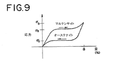
図9の応力−歪グラフは、代表的なニッケルチタン合金での、合金のオーステナイト化最終温度(Af)より高い温度における超弾性効果を示している。第1形態の合金に応力σaを掛けると、オーステナイトからマルテンサイトへの変態が始まる。合金のマルテンサイト相は、ほぼ一定の応力の数パーセントの歪を受け入れることができる。この例では8%の歪に相当する応力σbで、マルテンサイト変態が完了し、合金は第2形態に変形した。応力が取り除かれると、マルテンサイトは変態を開始してオーステナイトに戻り、合金はより低いプラトー応力σcの歪みを回復する。ニッケル−チタン合金は、而して、第1形態に戻る。 The stress-strain graph of FIG. 9 shows the superelastic effect at a temperature higher than the final austenitizing temperature (A f ) of a typical nickel titanium alloy. When stress σ a is applied to the first form alloy, transformation from austenite to martensite begins. The martensitic phase of the alloy can accept a few percent strain of a nearly constant stress. In this example, the martensitic transformation was completed at a stress σ b corresponding to a strain of 8%, and the alloy was transformed into the second form. When the stress is removed, martensite begins to transform back to austenite and the alloy recovers strain with a lower plateau stress σ c . The nickel-titanium alloy thus returns to the first form.
図10は、代表的なニッケル−チタン形状記憶合金の典型的な変態温度曲線を示しており、同図で、y軸は合金中のマルテンサイトの量を表し、x軸は温度を表している。Af又はそれより高い温度では、ニッケル−チタン合金は全オーステナイト構造を有している。矢印に従い、合金を温度Msまで冷却し得、この温度でマルテンサイト相への変態が始まる。更に冷却すると、材料中のマルテンサイトの割合が増加し、最終的に図10に示す温度Mfで全マルテンサイト構造になる。 FIG. 10 shows a typical transformation temperature curve for a typical nickel-titanium shape memory alloy, where the y-axis represents the amount of martensite in the alloy and the x-axis represents the temperature. . At Af or higher temperatures, nickel-titanium alloys have a full austenite structure. In accordance with the arrow, obtained by cooling the alloy to a temperature M s, transformation to martensite phase begins at this temperature. When further cooled, the ratio of martensite in the material increases, and finally the entire martensite structure is obtained at the temperature M f shown in FIG.
次に、代表的なニッケル−チタン形状記憶合金の歪対温度を示している図11を参照すると、温度Mfで獲得された全マルテンサイト構造は、(応力記号σで示されているように)歪みが変化して第1形態から第2形態になり得る。合金は、数パーセントの回復可能な歪(この例では8%)には対応することができる。相変態を逆転させ歪を回復するには、合金の温度を上昇させねばならない。ここでまた矢印に従い、ニッケル−チタン合金を温度Asまで加熱し得、この温度で合金はオーステナイト相への変態を開始する。更に加熱すると、オーステナイトへの変態が進行し、合金は徐々に第1形態を回復する。最終的に、Af又はそれより高い温度で、材料は、オーステナイト相への復帰変態を完了し(0%マルテンサイト相)、8%の歪を完全に回復した。 Referring now to FIG. 11, which shows the strain versus temperature of a representative nickel-titanium shape memory alloy, the total martensite structure obtained at temperature M f is (as indicated by the stress symbol σ). ) The distortion can change from the first form to the second form. The alloy can accommodate a few percent recoverable strain (8% in this example). To reverse the phase transformation and restore strain, the temperature of the alloy must be increased. According Here again the arrows, nickel - obtained by heating a titanium alloy to a temperature A s, the alloy at this temperature starts transformation to the austenitic phase. Upon further heating, the transformation to austenite proceeds and the alloy gradually recovers the first form. Finally, at A f or higher, the material completed the transformation back to the austenite phase (0% martensite phase) and fully recovered the 8% strain.
一般的に、形状記憶の記憶効果は一方向に限られており、それは、1つの形態から別の形態への自発的変化が、加熱時に限って生じることを意味する。図11に示しているように、遷移温度より低い温度で第2形態を得るには、一般に、応力を加えることが必要である。しかしながら、形状記憶材料が加熱時のみならず冷却時にも自発的に形状を変化させる二方向形状記憶効果を得ることは可能である。1つの態様によれば、補強部材35の形状記憶材料は、二方向の形状記憶挙動を呈してもよい。例えば、固定要素30の送達形態は、Mf又はそれより低い温度まで冷却すれば、外から応力を掛けなくても獲得することができる。
In general, the memory effect of shape memory is limited to one direction, which means that the spontaneous change from one form to another occurs only during heating. As shown in FIG. 11, in order to obtain the second form at a temperature lower than the transition temperature, it is generally necessary to apply stress. However, it is possible to obtain a two-way shape memory effect in which the shape memory material spontaneously changes its shape not only when it is heated but also when it is cooled. According to one aspect, the shape memory material of the reinforcing
図12Aから図12Dを参照すると、ステント5を配備するのに超弾性効果が利用されていてもよい。換言すると、形状記憶材料は、掛けられら応力が取り除かれたことに反応して、マルテンサイト相から、ステント5の配備のため、オーステナイト相へ変態してもよい。この態様によれば、ステント5は、各図に示しているようにステント5に内挿された硬いワイヤーガイド55か又はステントに外挿されたシースの様な拘束部材50によって、送達形態に維持することができる。(単数又は複数の)固定要素30が、管状本体10と一体化されているピグテール32又は同様の構造である場合は、内挿されたワイヤーガイド55で充分であるが、(単数又は複数の)固定要素がフラップ34である場合には外挿されたシースが必要となるかもしれない。形状記憶材料は、拘束部材50によって拘束されている時は、マルテンサイト相を備え得るのが望ましい。ステント5の補強部材35、ひいては固定要素30は、図12Aから図12Dに示している様に、治療部位で、拘束部材50が取り出されるか又は引き戻され、マルテンサイトがオーステナイトに変態した時、送達形態から配備形態(例えば、ピグテール)に変化してもよい。補強部材35の形状記憶材料は、ステント5が治療部位に配置されたら、拘束部材50(ワイヤーガイド55)を取り出すだけでオーステナイト相への変態が引き起こされるように、体温(37℃)以下のオーステナイト化最終温度(Af)を有しているのが望ましい。一例として、形状記憶材料は、約27℃から37℃の範囲のAf値を有していてもよい。代わりに、Afは、約32℃から37℃の範囲にあってもよい。Afが27℃未満ということもあり得る。更に、Asが周囲温度(例えば、約20℃)より高い場合は、ステント5の形状記憶材料は室温ではマルテンサイトであり得る。
With reference to FIGS. 12A to 12D, the superelastic effect may be utilized to deploy the stent 5. In other words, the shape memory material may transform from the martensite phase to the austenite phase for deployment of the stent 5 in response to the applied stress being removed. According to this aspect, the stent 5 is maintained in the delivery configuration by a
図13Aから図13Eを参照すると、ステント5を配備するのに形状記憶効果が利用されていてもよい。この態様によれば、拘束部材50は使用しなくてもよい。補強部材35には、体温(37℃)より高く、但し組織を傷つける可能性がある温度より低いAf値を有する形状記憶材料が選定されてもよい。例えば、形状記憶材料は、約38℃から約58℃の範囲のAf値を有していてもよい。或いは、Afは、約38℃から約50℃の範囲にあってもよい。従って、ステント5は、体内を進められている時は、マルテンサイト構造を有している。ステント5が治療部位で所定位置にある時、ステント5(補強部材35)は、Af又はそれより高い温度まで加温される。その結果、マルテンサイトはオーステナイトに変態し得、(単数又は複数の)固定要素30は配備形態に至り、ステント5を管内に錨着し得る。加温作業は、図13Aから図13Eに示している様に、例えば、ワイヤーガイド55を取り出し、生体適合性を有する温かい流体(例えば、温かい生理食塩水)をステントのルーメンに流す作業を伴うものでもよい。代わりに、ワイヤーガイド55又は随意の案内カテーテルが、流体を流せるように対応したルーメンを含んでいてもよい。この態様によれば、ワイヤーガイド55は、ステント5を配置するためのガイドとして利用されていてもよいが、送達形態を維持する拘束部材50としては必要とされていない。配備形態が得られると、加熱は中止され、ステント5は、管内で配備形態を取ったままになり得る。ステント5が管内の所定位置にある間、形状記憶合金のオーステナイト構造を維持するために、Mf、望ましくはMsが体温より低い形状記憶合金を選定してもよい。オーステナイトはマルテンサイトより頑丈で変形し難いので、ステント5が第2形態で配備された時、形状記憶合金のオーステナイト相を保持することが望ましいこともある。MfとMsが体温以上である場合は、配備中、ステント5を継続的に加熱して、望まれていないマルテンサイトへの相変態を阻止する必要があるかもしれない。
Referring to FIGS. 13A-13E, the shape memory effect may be utilized to deploy the stent 5. According to this aspect, the restraining member 50 may not be used. For the reinforcing
代わりの或る態様によれば、補強部材35の形状記憶材料は、補強部材35が体温程度に温められるとオーステナイト構造に変態して配備形態(例えば、ピグテール)を取るように、体温(37℃)以下の値Afを有していてもよい。例えば、形状記憶材料は、約27℃から約37℃の範囲のAf値を有していてもよい。代わりに、Afは、約32℃から約37℃の範囲にあってもよい。Afが27℃未満ということもあり得る。この態様によれば、ステント5(補強部材35)は、マルテンサイト構造が、時期を早めてオーステナイトに変態するのを防止するため、送達中の冷却が必要になるかもしれない。冷却には、ステント5を体内で進めながら、例えば、生体適合性を有する低温流体(例えば、低温の生理食塩水)を送達システムを通して流すことによって、補強部材35をAsより低い温度に維持することが伴う場合もある。流体を流せるように対応するため、ワイヤーガイド55又は案内カテーテルはルーメンを含んでいてもよい。
According to an alternative embodiment, the shape memory material of the
更に別の実施形態によれば、補強部材35は、高い降伏応力と低い弾性係数を有する弾性材料で形成されていてもよい。材料の応力−歪み線図は、曲線の直線状(弾性)部分の下に大きな面積を含んでいることがある。その様な材料であれば、弾性的に変形できる量が、一般的な金属及び合金より多くなり得る。弾性材料の一例として高炭素ばね鋼がある。この実施形態によれば、弾性材料は、応力の印加と除去により、或る形態から別の形態に変化させることができる。例えば、ステントは、管の中へ送達する場合、拘束部材(例えば、内挿された硬いガイドワイヤー又は外挿されたシース)によって送達形態に保持されていてもよい。上で指摘したように、弾性材料の弾性のおかげで、送達形態は柔軟であるため、送達中は管腔又は管内の起伏及び/又は蛇行に対応するように変化することができる。ステントは、治療部位で所定位置にある時、拘束部材が取り出されるか引き戻されると、配備形態に復帰し得る。
According to still another embodiment, the reinforcing
ここでは非拡張性ステントを体内通路に配備する方法を説明する。遠位部分と近位部分と遠位部分と近位部分の間の長手方向中央部分を含む管状本体を有するステントを用意する。管状本体は、少なくとも1つの固定要素を含んでいる。固定要素は、形状記憶材料を備えた補強部材を含んでいる。ステントを治療部位に配置するため、対象の管腔又は管の中へ送達する。固定要素は、ステントの治療部位への送達を支援する、補強部材の送達形態を有している。補強部材の送達形態は、管腔又は管内の起伏及び/又は蛇行に対応するため柔軟であるのが望ましい。或る好適な実施形態によれば、補強部材は、送達形態では、形状記憶材料のマルテンサイト相を含んでいてもよい。 Here, a method of deploying a non-expandable stent in a body passage is described. A stent is provided having a tubular body that includes a distal portion, a proximal portion, and a longitudinal central portion between the distal portion and the proximal portion. The tubular body includes at least one securing element. The securing element includes a reinforcing member with a shape memory material. The stent is delivered into the subject lumen or tube for placement at the treatment site. The anchoring element has a reinforcing member delivery configuration that assists in delivery of the stent to the treatment site. The delivery form of the reinforcing member is desirably flexible to accommodate undulations and / or serpentine within the lumen or tube. According to certain preferred embodiments, the reinforcing member may comprise a martensitic phase of shape memory material in the delivery configuration.
ステントを治療部位に送達するのに、内視鏡、ワイヤーガイド、随意の案内カテーテル、及び押出カテーテルを含んでいる導入システムを用いてもよい。本方法の幾つかの態様によれば、ステントに体内を通過させる際、補強部材の送達形態を維持するために、拘束部材(例えば、シース又はワイヤーガイド)が必要とされる場合がある。 An delivery system that includes an endoscope, wire guide, optional guide catheter, and pusher catheter may be used to deliver the stent to the treatment site. According to some aspects of the method, a restraining member (eg, a sheath or wire guide) may be required to maintain the delivery configuration of the reinforcing member as it passes through the body through the stent.
図14Aを参照すると、ワイヤーガイド55は、十二指腸75内に配置された内視鏡90を通して進められ、対象の管60の中へ誘導され得る。ワイヤーガイド55の遠位端を、治療部位(例えば、狭窄部)80の遠位側に置くことができる。次いで、ステント5をワイヤガイド55に外挿して内視鏡90を通して進め、図14Bに示しているように、管60内の治療部位80の付近に設置する。同処置は、ステント5及び/又は案内カテーテルに取り付けられた放射線不透過性マーカーを使って蛍光透視法誘導下に行ってもよい。
Referring to FIG. 14A, the
図14Cは、管60内の配備位置にあるステント5を示している。ステントを配備するに当たり、ワイヤーガイド55と随意の案内カテーテル(図では確認できない)を取り出してもよい。ステント5を配備するため、1つ又はそれ以上の補強部材35と、ひいては1つ又は複数の固定要素30は、図14Dに示す配備形態を獲得する。本方法の1つの態様によれば、配備には、補強部材35の形状記憶材料のマルテンサイトからオーステナイトへの相変化が含まれる。ステント5は、1つの態様によれば、拘束部材30を取り出すことによって、超弾性的に配備されてもよい。例えば、ステント5に外挿されたシース又はステント5に内挿された硬いワイヤーガイド55を引き戻して、1つ又は複数の固定要素30の配備が引き起こされるようにしてもよい。別の実施形態によれば、ステント5は、補強部材35の形状記憶材料の温度変化によって配備されてもよい。ステント5は、補強部材35の形状記憶材料がAs又は望ましくはAfの温度に到達するか又は超えるように加温されてもよい。As又はAfが体温以下である実施形態によれば、補強部材35は、身体の管腔又は管の温度により温められて配備形態になってもよい。代わりに、As又はAfが体温より高い実施形態によれば、補強部材35の加温は、加温用の流体をステント5の送達システムを通して循環させることにより起こしてもよい。ステント5がひとたび配備されてしまうと、固定要素30は、例えば、フラップ34又はピグテール32を含んだ配備形態を有している。
FIG. 14C shows the stent 5 in a deployed position within the
形状記憶材料は、等価原子の又はほぼ等価原子の二元ニッケル−チタン合金(例えば、ニチノール)であるのが望ましい。その様なニッケル−チタン組成物は、当技術では知られており、スペシャル・メタルズ社(Special Metals Corp)(ニューヨーク州ニューハートフォード)、メムリー社(Memry Corp.)(コネチカット州ベスル)、及びジョンソン・マッセイ社(Johnson Matthey, Inc.)(ペンシルベニア州ウエストチェスター)を含め多くの市販品供給業者から入手することができる。形状記憶材料は、更に、三元又は四元添加物の様な添加合金化元素を含んでいてもよい。その様な添加合金化元素は、アルミニウム、ホウ素、クロム、コバルト、銅、金、ハフニウム、鉄、マンガン、ニオビウム、パラジウム、プラチナ、タンタル、タングステン、バナジウム、及びジルコニウムから成るグループから選択することができる。 The shape memory material is preferably a binary nickel-titanium alloy (e.g., nitinol) of equivalent or near equivalent atoms. Such nickel-titanium compositions are known in the art and include Special Metals Corp (New Hartford, NY), Memry Corp. (Bethel, CT), and Johnson. • Available from a number of commercial suppliers including Johnson Matthey, Inc. (Westchester, PA). The shape memory material may further contain additional alloying elements such as ternary or quaternary additives. Such additive alloying elements can be selected from the group consisting of aluminum, boron, chromium, cobalt, copper, gold, hafnium, iron, manganese, niobium, palladium, platinum, tantalum, tungsten, vanadium, and zirconium. .
ここで、更に、本開示による非拡張性ステントを製作する方法を説明する。形状記憶材料を備えている少なくとも1つの補強部材(例えば、ワイヤー)を提供してもよい。ステントを成形する前に、形状記憶/超弾性の特性を補強部材に付与するのが望ましい。例えば、所望の最終形状の「記憶」を付与するため、及び補強部材の形状記憶/超弾性の特性を最適化するために、熱処理を採用してもよい。当業者には知られているように、熱処理の回数、時間、及び温度によって、形状記憶材料の変態温度が変わり得る。通常は、350℃から550℃の熱処理温度が採用される。 Now, a method of making a non-expandable stent according to the present disclosure will be further described. At least one reinforcing member (eg, wire) comprising a shape memory material may be provided. It is desirable to impart shape memory / superelastic properties to the reinforcement member prior to shaping the stent. For example, heat treatment may be employed to provide a “memory” of the desired final shape and to optimize the shape memory / superelastic properties of the reinforcing member. As known to those skilled in the art, the transformation temperature of the shape memory material can vary depending on the number of heat treatments, time and temperature. Usually, a heat treatment temperature of 350 ° C. to 550 ° C. is employed.
次に、補強部材を、その長さに沿ってマンドレルとの間に所望の間隔を取った状態で、マンドレルに隣接して保持してもよい。補強部材を、所望の間隔と所望の配置でマンドレルに隣接して保持するために、固定具を採用してもよい。補強部材をマンドレルに隣接して配置する前に、補強部材を形状記憶材料のMfより低く冷却して、補強部材の変形し易さ及び拘束し易さが改善されるようにするのが好都合であり得る。マンドレルと補強部材の間隔は長さに沿って可変であっても一定であってもよい。間隔は、ステントの所望の壁厚及びステントの壁内の補強部材の好適な配置によるが、一例として、約0.01mmから約2mmの範囲にあってもよい。補強部材は、形成されたステントの外壁と内壁の間に、等距離に配置されているのが望ましい。1つの実施形態によれば、マンドレルと補強部材の間隔は、約0.05mmから約1mmの範囲にある。 The reinforcing member may then be held adjacent to the mandrel with a desired spacing between it and the mandrel. A fixture may be employed to hold the reinforcing member adjacent to the mandrel at the desired spacing and desired arrangement. Prior to placing the reinforcement member adjacent to the mandrel, it is advantageous to cool the reinforcement member below the Mf of the shape memory material so that it is easier to deform and constrain the reinforcement member. It can be. The spacing between the mandrel and the reinforcing member may be variable or constant along the length. The spacing depends on the desired wall thickness of the stent and the preferred placement of the reinforcing members within the stent wall, but as an example may be in the range of about 0.01 mm to about 2 mm. The reinforcing members are preferably arranged equidistant between the outer and inner walls of the formed stent. According to one embodiment, the spacing between the mandrel and the reinforcing member is in the range of about 0.05 mm to about 1 mm.
非拡張性ステントを形成するため、次に、被覆用溶液を補強部材及びマンドレルに塗布してもよい。1つの実施形態によれば、被覆用溶液は、浸漬により塗布されてもよい。代わりに、被覆用溶液は、吹き付け、スピニング、又は当技術で知られている他の被覆法によって塗布してもよい。被覆用溶液は、周囲温度で塗布してもよい。 A coating solution may then be applied to the reinforcing member and mandrel to form a non-expandable stent. According to one embodiment, the coating solution may be applied by dipping. Alternatively, the coating solution may be applied by spraying, spinning, or other coating methods known in the art. The coating solution may be applied at ambient temperature.
被覆用溶液は、補強部材とマンドレルに塗布された後、硬化し、それらの表面にポリマー層を形成し得る。硬化は、当技術で知られている何れの硬化方法により実施してもよい。硬化は、例えば、加熱、放射線(例えば、紫外線、電子ビーム)、又は薬品を使って実施することができる。被覆用溶液を塗布し硬化させる段階を順次繰り返して、補強部材とマンドレルの表面に次々に重ねられたポリマー層を形成するのが望ましい。例えば、浸漬と硬化の段階を10回から20回連続して使用してもよい。この様にして、所望の壁厚を有する非拡張性ステントが形成され得る。所望の壁厚が得られた後、マンドレルを取り出し、これによりステントのルーメンを形成してもよい。補強部材は、所望の長さに切断してもよい。 The coating solution can be applied to the reinforcing member and mandrel and then cured to form a polymer layer on the surfaces thereof. Curing may be performed by any curing method known in the art. Curing can be performed using, for example, heating, radiation (eg, ultraviolet light, electron beam), or chemicals. It is desirable to sequentially repeat the steps of applying and curing the coating solution to form a polymer layer that is successively stacked on the surfaces of the reinforcing member and the mandrel. For example, the immersion and curing steps may be used continuously 10 to 20 times. In this way, non-expandable stents with the desired wall thickness can be formed. After the desired wall thickness is obtained, the mandrel may be removed, thereby forming the lumen of the stent. The reinforcing member may be cut to a desired length.
ステントの長さを切り揃える際、補強部材の端は、ステント内に埋まっているかステントの端と面一になっているのが望ましい。必要に応じて、UV硬化性接着剤をステントの一端又は両端に塗布して、補強部材の露出部を覆うようにポリマー層を形成し、それにより、ステント送達中に補強部材と管腔又は管の壁の間の外傷の可能性を低減するようにしてもよい。補強部材の露出部分を覆う手段として、切断したステントを別のポリマーでオーバーモールドすることも可能である。 When trimming the length of the stent, it is desirable that the end of the reinforcing member is embedded in the stent or flush with the end of the stent. Optionally, a UV curable adhesive is applied to one or both ends of the stent to form a polymer layer over the exposed portion of the reinforcement member, thereby providing the reinforcement member and lumen or tube during stent delivery. The possibility of trauma between the walls may be reduced. It is also possible to overmold the cut stent with another polymer as a means to cover the exposed portion of the reinforcing member.
非拡張性ステント及び同ステントを製作及び配備する方法を開示した。ステントは、形状記憶材料で形成された補強部材を備えた少なくとも1つの固定要素を有している。ステントは、固定要素の形態を送達形態から配備形態へ変化させることによって、膵管の様な体内通路の狭窄部付近に配備される。1つの態様によれば、応力及び/又は温度の変化に起因する形状記憶材料の相の変化によって、ステントの配備が誘起される。本開示の非拡張性ステントは、安価な周囲温度被覆法によって形成することができる。対照的に、従来の膵管又は胆管ステントは、一般的に、高温で押出成形し、続いて熱成形し、配備形態に固化させることにより製造されている。従って、従来の膵管又は胆管ステントは、概して、熱可塑性ポリマーに限定される。対照的に、本開示のステントは、例えば、ソラロンの様な、望ましい特性を有する広範囲の様々なポリマーから形成することができる。 A non-expandable stent and a method of making and deploying the stent have been disclosed. The stent has at least one anchoring element with a reinforcing member formed of a shape memory material. Stents are deployed near a stenosis in a body passage such as the pancreatic duct by changing the configuration of the anchoring element from a delivery configuration to a deployed configuration. According to one aspect, a change in shape memory material phase resulting from a change in stress and / or temperature induces stent deployment. The non-expandable stent of the present disclosure can be formed by an inexpensive ambient temperature coating method. In contrast, conventional pancreatic or biliary stents are typically manufactured by extrusion at elevated temperatures followed by thermoforming and solidifying into a deployed configuration. Thus, conventional pancreatic or biliary stents are generally limited to thermoplastic polymers. In contrast, the stents of the present disclosure can be formed from a wide variety of polymers having desirable properties, such as, for example, solaron.
従って、前述の詳細な説明は、限定ではなく説明を目的としたものであると見なされるものとし、本発明の精神及び範囲を定義することを目的としているのは、特許請求の範囲並びに全ての等価物であると理解されるものとする。 Accordingly, the foregoing detailed description is to be regarded as illustrative rather than restrictive, and is intended to define the spirit and scope of the invention as defined by the appended claims and all It should be understood as equivalent.
Claims (12)
遠位部分と、近位部分と、前記遠位部分と前記近位部分の間の長手方向中央部分と、実質的に非拡張性の直径と、を有する管状本体を備えており、
前記管状本体は、前記管状本体と一体的に形成された少なくとも1つの固定要素を含み、前記管状本体はポリマーからなり、前記固定要素は、前記ポリマーに埋め込まれたニッケル−チタン合金の形状記憶材料からなる補強部材を含み、前記補強部材は前記管状本体の長さの少なくとも一部に沿って延在しており、
前記固定要素は、身体の管腔内の治療部位への送達を支援する補強部材の第1形態と、前記治療部位での配備を支援する補強部材の第2形態と、を備え、前記補強部材は、前記第1形態では前記ニッケル−チタン合金がマルテンサイト相を有し、前記第2形態では前記ニッケル−チタン合金がオーステナイト相を有しており、
前記固定要素は、前記補強部材が前記第1形態にある時は、当該ステントを前記身体の管腔を通して動かし易くするように構成されているステント。 In non-expandable stents,
A tubular body having a distal portion, a proximal portion, a longitudinal central portion between the distal portion and the proximal portion, and a substantially non-expandable diameter;
Said tubular body, said saw including a tubular body and at least one fixing element is integrally formed, the tubular body is made of a polymer, wherein the fixing element, nickel embedded in the polymer - shape memory titanium alloy look including a reinforcing member made of a material, the reinforcing member extends along at least a portion of the length of said tubular body,
The securing element comprises a first form of a reinforcing member that assists in delivery to a treatment site within a body lumen, and a second form of a reinforcing member that aids deployment at the treatment site, the reinforcing member In the first embodiment, the nickel-titanium alloy has a martensite phase, and in the second embodiment, the nickel-titanium alloy has an austenite phase,
The stent is configured to facilitate movement of the stent through the body lumen when the reinforcing member is in the first configuration .
ニッケル−チタン合金の形状記憶材料からなる少なくとも1つの補強部材であって、前記補強部材の長さに沿ってマンドレルと間隔を取った状態で、前記マンドレルに隣接して保持されるように補強部材を用意する段階と、
被覆用溶液を前記補強部材と前記マンドレルに塗布する段階と、
前記被覆用溶液を硬化させて、前記補強部材と前記マンドレル上にポリマー層を形成し、それによって、該管状本体と一体的に形成された少なくとも1つの固定要素であって、前記補強部材が前記ポリマー層に埋め込まれている固定要素を備え、実質的に非拡張性の直径を有する管状本体を形成する段階と、
前記マンドレルを取り出し、それによって、前記固定要素が、身体の管腔内の治療部位への送達を支援する補強部材の第1形態と、前記治療部位での配備を支援する補強部材の第2形態と、を備え、前記補強部材は、前記第1形態では前記ニッケル−チタン合金がマルテンサイト相を有し、前記第2形態では前記ニッケル−チタン合金がオーステナイト相を有しており、前記固定要素は、前記補強部材が前記第1形態にある時は、当該ステントを前記身体の管腔を通して動かし易くするように構成されている、非拡張性ステントを形成する段階と、から成る方法。 In a method of making a non-expandable stent,
Nickel - at least one reinforcing member made of a shape memory material titanium alloy, while taking the mandrel and the distance along the length of the reinforcing member, the reinforcing member to be held adjacent to said mandrel Preparing the stage,
Applying a coating solution to the reinforcing member and the mandrel;
Curing the coating solution to form a polymer layer on the reinforcement member and the mandrel, thereby at least one securing element integrally formed with the tubular body, wherein the reinforcement member is Forming a tubular body with a securing element embedded in the polymer layer and having a substantially non-expandable diameter;
A first form of reinforcement member that removes the mandrel so that the anchoring element assists delivery to a treatment site within a body lumen and a second form of reinforcement member that aids deployment at the treatment site. In the first embodiment, the reinforcing member has the martensitic phase in the nickel-titanium alloy, and the nickel-titanium alloy has an austenitic phase in the second form. Forming a non-expandable stent configured to facilitate movement of the stent through the body lumen when the reinforcing member is in the first configuration .
The method of claim 11 , wherein the step of applying and curing is sequentially repeated prior to the step of removing the mandrel to form a polymer layer successively stacked on the reinforcing member and the mandrel.
Applications Claiming Priority (3)
| Application Number | Priority Date | Filing Date | Title |
|---|---|---|---|
| US85203406P | 2006-10-16 | 2006-10-16 | |
| US60/852,034 | 2006-10-16 | ||
| PCT/US2007/081460 WO2008115271A2 (en) | 2006-10-16 | 2007-10-16 | Nonexpandable stent |
Publications (3)
| Publication Number | Publication Date |
|---|---|
| JP2010506685A JP2010506685A (en) | 2010-03-04 |
| JP2010506685A5 JP2010506685A5 (en) | 2010-12-02 |
| JP5302891B2 true JP5302891B2 (en) | 2013-10-02 |
Family
ID=39766643
Family Applications (1)
| Application Number | Title | Priority Date | Filing Date |
|---|---|---|---|
| JP2009533472A Active JP5302891B2 (en) | 2006-10-16 | 2007-10-16 | Non-expandable stent |
Country Status (6)
| Country | Link |
|---|---|
| US (1) | US20080091275A1 (en) |
| EP (1) | EP2081628B1 (en) |
| JP (1) | JP5302891B2 (en) |
| AU (1) | AU2007349205B2 (en) |
| CA (1) | CA2665868C (en) |
| WO (1) | WO2008115271A2 (en) |
Families Citing this family (15)
| Publication number | Priority date | Publication date | Assignee | Title |
|---|---|---|---|---|
| US20080097620A1 (en) | 2006-05-26 | 2008-04-24 | Nanyang Technological University | Implantable article, method of forming same and method for reducing thrombogenicity |
| US10898620B2 (en) | 2008-06-20 | 2021-01-26 | Razmodics Llc | Composite stent having multi-axial flexibility and method of manufacture thereof |
| US8206636B2 (en) | 2008-06-20 | 2012-06-26 | Amaranth Medical Pte. | Stent fabrication via tubular casting processes |
| US8206635B2 (en) * | 2008-06-20 | 2012-06-26 | Amaranth Medical Pte. | Stent fabrication via tubular casting processes |
| US8603185B2 (en) * | 2010-03-11 | 2013-12-10 | Cook Medical Technologies Llc | Stent geometry |
| AU2012230966B2 (en) | 2011-03-22 | 2017-05-11 | Applied Medical Resources Corporation | Method of making medical tubing having drainage holes |
| JP6125633B2 (en) * | 2012-07-20 | 2017-05-10 | クック・メディカル・テクノロジーズ・リミテッド・ライアビリティ・カンパニーCook Medical Technologies Llc | Anti-slip biliary stent |
| JP5408682B1 (en) * | 2013-06-28 | 2014-02-05 | ガデリウス・メディカル株式会社 | Stent kit |
| US9242079B2 (en) * | 2013-11-12 | 2016-01-26 | Gyrus Acmi, Inc. | Ureteral stents with waveform interlayers and interstitching |
| CN104001256A (en) * | 2014-06-13 | 2014-08-27 | 胡冰 | Good-compliance stent placed in left hepatic duct of human body |
| AU2020339448B2 (en) | 2019-08-29 | 2024-03-21 | Deepqure Inc. | Electrode device for wrapping around vessels in body, and method therefor |
| CN114340720B (en) * | 2019-08-29 | 2024-12-20 | 迪普库雷公司 | Electrode device and method for surrounding a tube in a body |
| US20230233312A1 (en) * | 2022-01-21 | 2023-07-27 | Covidien Lp | Stent design for transluminal application |
| CN114593001B (en) * | 2022-03-14 | 2024-01-09 | 德阳市东方恒运电机有限公司 | Assembling method between control ring and outer water distribution ring of through-flow turbine |
| CN119654117A (en) * | 2022-08-22 | 2025-03-18 | 株式会社钟化 | Stent kit, stent system having stent kit, and method of manufacturing stent kit |
Family Cites Families (27)
| Publication number | Priority date | Publication date | Assignee | Title |
|---|---|---|---|---|
| US4212304A (en) * | 1978-04-07 | 1980-07-15 | Medical Engineering Corp. | Uretheral catheter stent |
| US4307723A (en) * | 1978-04-07 | 1981-12-29 | Medical Engineering Corporation | Externally grooved ureteral stent |
| US4675361A (en) * | 1980-02-29 | 1987-06-23 | Thoratec Laboratories Corp. | Polymer systems suitable for blood-contacting surfaces of a biomedical device, and methods for forming |
| US4874360A (en) * | 1988-07-01 | 1989-10-17 | Medical Engineering Corporation | Ureteral stent system |
| US4931037A (en) * | 1988-10-13 | 1990-06-05 | International Medical, Inc. | In-dwelling ureteral stent and injection stent assembly, and method of using same |
| US5964744A (en) * | 1993-01-04 | 1999-10-12 | Menlo Care, Inc. | Polymeric medical device systems having shape memory |
| US5716410A (en) * | 1993-04-30 | 1998-02-10 | Scimed Life Systems, Inc. | Temporary stent and method of use |
| IL105828A (en) * | 1993-05-28 | 1999-06-20 | Medinol Ltd | Medical stent |
| US5486191A (en) * | 1994-02-02 | 1996-01-23 | John Hopkins University | Winged biliary stent |
| DE4446036C2 (en) * | 1994-12-23 | 1999-06-02 | Ruesch Willy Ag | Placeholder for placement in a body tube |
| US5830179A (en) * | 1996-04-09 | 1998-11-03 | Endocare, Inc. | Urological stent therapy system and method |
| US6395021B1 (en) * | 1997-02-26 | 2002-05-28 | Applied Medical Resources Corporation | Ureteral stent system apparatus and method |
| US5876450A (en) * | 1997-05-09 | 1999-03-02 | Johlin, Jr.; Frederick C. | Stent for draining the pancreatic and biliary ducts and instrumentation for the placement thereof |
| WO1999042036A1 (en) * | 1998-02-20 | 1999-08-26 | General Surgical Innovations, Inc. | Bendable, reusable medical instruments with improved fatigue life |
| US6746489B2 (en) * | 1998-08-31 | 2004-06-08 | Wilson-Cook Medical Incorporated | Prosthesis having a sleeve valve |
| US6517573B1 (en) * | 2000-04-11 | 2003-02-11 | Endovascular Technologies, Inc. | Hook for attaching to a corporeal lumen and method of manufacturing |
| WO2001076675A2 (en) * | 2000-04-11 | 2001-10-18 | Scimed Life Systems, Inc. | Reinforced retention structures |
| US6764519B2 (en) | 2000-05-26 | 2004-07-20 | Scimed Life Systems, Inc. | Ureteral stent |
| WO2002015951A2 (en) * | 2000-08-23 | 2002-02-28 | Thoratec Corporation | Coated vascular grafts and methods of use |
| DE20119322U1 (en) * | 2000-11-21 | 2002-02-21 | Schering Ag, 13353 Berlin | Tubular vascular grafts (stents) |
| US6620202B2 (en) * | 2001-10-16 | 2003-09-16 | Scimed Life Systems, Inc. | Medical stent with variable coil and related methods |
| US7041139B2 (en) * | 2001-12-11 | 2006-05-09 | Boston Scientific Scimed, Inc. | Ureteral stents and related methods |
| US6913625B2 (en) * | 2002-03-07 | 2005-07-05 | Scimed Life Systems, Inc. | Ureteral stent |
| US7875068B2 (en) * | 2002-11-05 | 2011-01-25 | Merit Medical Systems, Inc. | Removable biliary stent |
| US7357818B2 (en) * | 2003-03-26 | 2008-04-15 | Boston Scientific Scimed, Inc. | Self-retaining stent |
| US7338530B2 (en) * | 2003-11-24 | 2008-03-04 | Checkmed Systems, Inc. | Stent |
| US8585753B2 (en) * | 2006-03-04 | 2013-11-19 | John James Scanlon | Fibrillated biodegradable prosthesis |
-
2007
- 2007-10-16 US US11/873,167 patent/US20080091275A1/en not_active Abandoned
- 2007-10-16 AU AU2007349205A patent/AU2007349205B2/en active Active
- 2007-10-16 WO PCT/US2007/081460 patent/WO2008115271A2/en active Application Filing
- 2007-10-16 JP JP2009533472A patent/JP5302891B2/en active Active
- 2007-10-16 CA CA2665868A patent/CA2665868C/en active Active
- 2007-10-16 EP EP07874399.4A patent/EP2081628B1/en active Active
Also Published As
| Publication number | Publication date |
|---|---|
| AU2007349205B2 (en) | 2013-05-23 |
| US20080091275A1 (en) | 2008-04-17 |
| AU2007349205A1 (en) | 2008-09-25 |
| CA2665868A1 (en) | 2008-09-25 |
| WO2008115271A3 (en) | 2009-02-26 |
| WO2008115271A2 (en) | 2008-09-25 |
| JP2010506685A (en) | 2010-03-04 |
| CA2665868C (en) | 2013-08-06 |
| EP2081628A2 (en) | 2009-07-29 |
| EP2081628B1 (en) | 2013-06-12 |
Similar Documents
| Publication | Publication Date | Title |
|---|---|---|
| JP5302891B2 (en) | Non-expandable stent | |
| JP4722378B2 (en) | Radiopaque intraluminal medical device | |
| JP5220613B2 (en) | Stent | |
| EP1556115B1 (en) | Linearly expandable ureteral stent | |
| EP1539290B1 (en) | Method for making a shaped reinforcing member for medical device | |
| JP5208641B2 (en) | Intrapulse stent with a curved bridge for connecting adjacent hoops | |
| US7524329B2 (en) | Self contracting stent | |
| AU2003203791B2 (en) | Low profile improved radiopacity intraluminal medical device | |
| EP2044233B1 (en) | Implant having high fatigue resistance, delivery system, and method of use | |
| US20030187497A1 (en) | Curved nitinol stent for extremely tortuous anatomy | |
| JP2004358242A (en) | Improved radiopacity intraluminal medical device | |
| JP2004531347A (en) | Highly flexible and flexible stent | |
| EP2170219A1 (en) | Radially expandable stent | |
| AU2015243099B2 (en) | Intraluminal device with improved flexibility and durability | |
| EP1459707B1 (en) | Anvil bridge stent design | |
| EP1459708A1 (en) | Split-bridge stent | |
| CN112118812B (en) | Support frame | |
| US20140142683A1 (en) | Stent with elastomeric elements | |
| EP3281668B1 (en) | Solid wire ureteral stent |
Legal Events
| Date | Code | Title | Description |
|---|---|---|---|
| A521 | Request for written amendment filed |
Free format text: JAPANESE INTERMEDIATE CODE: A523 Effective date: 20101015 |
|
| A621 | Written request for application examination |
Free format text: JAPANESE INTERMEDIATE CODE: A621 Effective date: 20101015 |
|
| A711 | Notification of change in applicant |
Free format text: JAPANESE INTERMEDIATE CODE: A711 Effective date: 20120329 |
|
| A977 | Report on retrieval |
Free format text: JAPANESE INTERMEDIATE CODE: A971007 Effective date: 20120528 |
|
| A131 | Notification of reasons for refusal |
Free format text: JAPANESE INTERMEDIATE CODE: A131 Effective date: 20120605 |
|
| A601 | Written request for extension of time |
Free format text: JAPANESE INTERMEDIATE CODE: A601 Effective date: 20120904 |
|
| A602 | Written permission of extension of time |
Free format text: JAPANESE INTERMEDIATE CODE: A602 Effective date: 20120911 |
|
| A601 | Written request for extension of time |
Free format text: JAPANESE INTERMEDIATE CODE: A601 Effective date: 20121004 |
|
| A602 | Written permission of extension of time |
Free format text: JAPANESE INTERMEDIATE CODE: A602 Effective date: 20121012 |
|
| A601 | Written request for extension of time |
Free format text: JAPANESE INTERMEDIATE CODE: A601 Effective date: 20121101 |
|
| A602 | Written permission of extension of time |
Free format text: JAPANESE INTERMEDIATE CODE: A602 Effective date: 20121108 |
|
| A521 | Request for written amendment filed |
Free format text: JAPANESE INTERMEDIATE CODE: A523 Effective date: 20121205 |
|
| TRDD | Decision of grant or rejection written | ||
| A01 | Written decision to grant a patent or to grant a registration (utility model) |
Free format text: JAPANESE INTERMEDIATE CODE: A01 Effective date: 20130604 |
|
| A61 | First payment of annual fees (during grant procedure) |
Free format text: JAPANESE INTERMEDIATE CODE: A61 Effective date: 20130621 |
|
| R150 | Certificate of patent or registration of utility model |
Free format text: JAPANESE INTERMEDIATE CODE: R150 Ref document number: 5302891 Country of ref document: JP Free format text: JAPANESE INTERMEDIATE CODE: R150 |
|
| R250 | Receipt of annual fees |
Free format text: JAPANESE INTERMEDIATE CODE: R250 |
|
| R250 | Receipt of annual fees |
Free format text: JAPANESE INTERMEDIATE CODE: R250 |
|
| R250 | Receipt of annual fees |
Free format text: JAPANESE INTERMEDIATE CODE: R250 |
|
| R250 | Receipt of annual fees |
Free format text: JAPANESE INTERMEDIATE CODE: R250 |
|
| R250 | Receipt of annual fees |
Free format text: JAPANESE INTERMEDIATE CODE: R250 |
|
| R250 | Receipt of annual fees |
Free format text: JAPANESE INTERMEDIATE CODE: R250 |
|
| R250 | Receipt of annual fees |
Free format text: JAPANESE INTERMEDIATE CODE: R250 |
|
| R250 | Receipt of annual fees |
Free format text: JAPANESE INTERMEDIATE CODE: R250 |
|
| R250 | Receipt of annual fees |
Free format text: JAPANESE INTERMEDIATE CODE: R250 |