JP5295969B2 - Wavelength conversion laser device and image display device using the same - Google Patents
Wavelength conversion laser device and image display device using the same Download PDFInfo
- Publication number
- JP5295969B2 JP5295969B2 JP2009535956A JP2009535956A JP5295969B2 JP 5295969 B2 JP5295969 B2 JP 5295969B2 JP 2009535956 A JP2009535956 A JP 2009535956A JP 2009535956 A JP2009535956 A JP 2009535956A JP 5295969 B2 JP5295969 B2 JP 5295969B2
- Authority
- JP
- Japan
- Prior art keywords
- wavelength conversion
- wavelength
- laser
- conversion element
- light
- Prior art date
- Legal status (The legal status is an assumption and is not a legal conclusion. Google has not performed a legal analysis and makes no representation as to the accuracy of the status listed.)
- Expired - Fee Related
Links
Images


Classifications
-
- H—ELECTRICITY
- H01—ELECTRIC ELEMENTS
- H01S—DEVICES USING THE PROCESS OF LIGHT AMPLIFICATION BY STIMULATED EMISSION OF RADIATION [LASER] TO AMPLIFY OR GENERATE LIGHT; DEVICES USING STIMULATED EMISSION OF ELECTROMAGNETIC RADIATION IN WAVE RANGES OTHER THAN OPTICAL
- H01S3/00—Lasers, i.e. devices using stimulated emission of electromagnetic radiation in the infrared, visible or ultraviolet wave range
- H01S3/005—Optical devices external to the laser cavity, specially adapted for lasers, e.g. for homogenisation of the beam or for manipulating laser pulses, e.g. pulse shaping
-
- G—PHYSICS
- G02—OPTICS
- G02F—OPTICAL DEVICES OR ARRANGEMENTS FOR THE CONTROL OF LIGHT BY MODIFICATION OF THE OPTICAL PROPERTIES OF THE MEDIA OF THE ELEMENTS INVOLVED THEREIN; NON-LINEAR OPTICS; FREQUENCY-CHANGING OF LIGHT; OPTICAL LOGIC ELEMENTS; OPTICAL ANALOGUE/DIGITAL CONVERTERS
- G02F1/00—Devices or arrangements for the control of the intensity, colour, phase, polarisation or direction of light arriving from an independent light source, e.g. switching, gating or modulating; Non-linear optics
- G02F1/35—Non-linear optics
- G02F1/353—Frequency conversion, i.e. wherein a light beam is generated with frequency components different from those of the incident light beams
- G02F1/3542—Multipass arrangements, i.e. arrangements to make light pass multiple times through the same element, e.g. using an enhancement cavity
-
- H—ELECTRICITY
- H01—ELECTRIC ELEMENTS
- H01S—DEVICES USING THE PROCESS OF LIGHT AMPLIFICATION BY STIMULATED EMISSION OF RADIATION [LASER] TO AMPLIFY OR GENERATE LIGHT; DEVICES USING STIMULATED EMISSION OF ELECTROMAGNETIC RADIATION IN WAVE RANGES OTHER THAN OPTICAL
- H01S3/00—Lasers, i.e. devices using stimulated emission of electromagnetic radiation in the infrared, visible or ultraviolet wave range
- H01S3/005—Optical devices external to the laser cavity, specially adapted for lasers, e.g. for homogenisation of the beam or for manipulating laser pulses, e.g. pulse shaping
- H01S3/0092—Nonlinear frequency conversion, e.g. second harmonic generation [SHG] or sum- or difference-frequency generation outside the laser cavity
Landscapes
- Physics & Mathematics (AREA)
- Nonlinear Science (AREA)
- Electromagnetism (AREA)
- Optics & Photonics (AREA)
- Engineering & Computer Science (AREA)
- Plasma & Fusion (AREA)
- General Physics & Mathematics (AREA)
- Optical Modulation, Optical Deflection, Nonlinear Optics, Optical Demodulation, Optical Logic Elements (AREA)
- Lasers (AREA)
- Devices For Indicating Variable Information By Combining Individual Elements (AREA)
- Control Of Indicators Other Than Cathode Ray Tubes (AREA)
Abstract
Description
本発明は、基本波レーザ光の波長変換を行って波長変換レーザ光を出力する波長変換レーザ装置およびこれを用いた画像表示装置に関するものである。 The present invention relates to a wavelength conversion laser device that performs wavelength conversion of fundamental laser light and outputs wavelength conversion laser light, and an image display device using the same.
基本波レーザ光の波長を、波長変換素子の非線形光学現象を用いて、第2高調波(Second Harmonic Generation : SHG)、和周波、差周波等の変換波に波長変換を行う波長変換レーザ装置がある。 A wavelength conversion laser device that converts the wavelength of a fundamental laser beam into a converted wave such as a second harmonic generation (SHG), a sum frequency, or a difference frequency using a nonlinear optical phenomenon of a wavelength conversion element. is there.
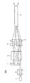
波長変換レーザ装置は、例えば図27に示すように、基本波レーザ光源101と、基本波レーザ光源101から出射された基本波レーザ光を集光するレンズ102と、集光した基本波レーザ光の第2高調波を発生する波長変換素子103と、基本波レーザ光と高調波レーザ光を分離するダイクロイックミラー104とからなる。
For example, as shown in FIG. 27, the wavelength conversion laser device includes a fundamental wave
波長変換素子103は、非線形光学結晶からなり、基本波と変換波との位相が整合するように、結晶の方位や分極反転構造等を適切に調節することにより、基本波の波長変換を行う。特に分極反転構造を用いた波長変換素子は、擬似位相整合により低パワーでも高効率の波長変換を行うことができ、設計により様々な波長変換を行うことができる。分極反転構造とは、非線形光学結晶103の自発分極を周期的に反転させた領域が設けられた構造である。
The
基本波から第2高調波に変換する変換効率ηは、波長変換素子の相互作用長をL、基本波のパワーをP、波長変換素子でのビーム断面積をA、位相整合条件からのずれをΔkとすると、
η∝L2P/A×sinc2(ΔkL/2)
とおける。また、相互作用長Lに対し適切な集光条件とした場合
η∝LP×sinc2(ΔkL/2)
となる。変換効率を高めるためには相互作用長Lを長くすると良いが、位相整合条件からのずれに対する許容幅がLに反比例する関係となるため、調整や基本波の条件が厳密となってしまうという問題がある。特に高出力の波長変換レーザ装置では、波長変換素子による基本波および変換波の吸収が生じて波長変換素子が発熱するため、波長変換素子の温度が不均一となり、変換効率が劣化してしまう。この現象は特に、波長変換レーザ光が強い場合顕著となる。
The conversion efficiency η for converting the fundamental wave to the second harmonic is L for the interaction length of the wavelength conversion element, P for the fundamental wave power, A for the beam cross-sectional area at the wavelength conversion element, and deviation from the phase matching condition. If Δk,
η∝L 2 P / A × sinc 2 (ΔkL / 2)
You can. In addition, when the light collection condition is appropriate for the interaction length L, η∝LP × sinc 2 (ΔkL / 2)
It becomes. In order to increase the conversion efficiency, it is preferable to increase the interaction length L. However, since the tolerance for deviation from the phase matching condition is inversely proportional to L, the adjustment and fundamental wave conditions become strict. There is. In particular, in a high-power wavelength conversion laser device, the wavelength conversion element is absorbed by the wavelength conversion element and heat is generated, so that the temperature of the wavelength conversion element becomes non-uniform and the conversion efficiency deteriorates. This phenomenon is particularly remarkable when the wavelength conversion laser beam is strong.
これまで、波長変換レーザ装置の変換効率を向上させるために、多くの提案がなされている。例えば、特許文献1では、複数個の波長変換素子と集光手段を用いることで、変換効率を高めることが提案されている。また、特許文献2では、波長変換素子に基本波レーザ光の反射体を設け、波長変換素子に基本波レーザ光を再入射させることが提案されている。また、特許文献3では、対向する反射鏡間に波長変換素子を配置し、往復する基本波レーザ光の波長変換を行うことが提案されている。また特許文献4では、共振器内に基本波レーザ光を注入し、共振器の光軸に基本波レーザ光を集中して、波長変換を行うことが提案されている。
Many proposals have been made so far in order to improve the conversion efficiency of the wavelength conversion laser device. For example,
しかしながら、従来提案されている構成は、波長変換レーザ装置の変換効率を向上させることはできるが、変換効率を高めたまま、位相整合条件からずれた場合の許容幅を拡大することなどは考慮されていない。位相整合条件からのずれに対する許容幅を拡大することは、装置としての安定性や信頼性を向上させることができ、装置の小型化なども可能とする。また、基本波レーザ光のパワーを非線形光学結晶内の一部に集中させると、光損傷や熱の発生により非線形光学結晶における波長変換を滞らせ、波長変換レーザ装置の変換動作が不安定となるという問題がある。 However, the conventionally proposed configuration can improve the conversion efficiency of the wavelength conversion laser device, but it is considered to increase the allowable range when deviating from the phase matching condition while increasing the conversion efficiency. Not. Increasing the allowable range for deviation from the phase matching condition can improve the stability and reliability of the device, and can also reduce the size of the device. Also, if the power of the fundamental laser beam is concentrated on a part of the nonlinear optical crystal, wavelength conversion in the nonlinear optical crystal is delayed due to optical damage or heat generation, and the conversion operation of the wavelength conversion laser device becomes unstable. There is a problem.
さらに、従来提案されている構成は、波長変換レーザ装置の低出力時の変換効率を向上させることはできるが、高出力時の発熱などを考慮していないため、高出力時の変換光率の劣化や温度制御を煩雑にするという問題がある。また、従来提案されている構成は、基本波レーザ光源を多モードのレーザ光源とした場合の変換効率の向上などは考慮されていない。 Furthermore, the conventionally proposed configuration can improve the conversion efficiency at the time of low output of the wavelength conversion laser device, but does not consider the heat generation at the time of high output, so the conversion light rate at the time of high output is not considered. There is a problem that the deterioration and temperature control are complicated. In addition, the conventionally proposed configuration does not consider improvement in conversion efficiency when the fundamental laser light source is a multimode laser light source.
また、波長変換レーザ装置では、位相整合条件が厳密であるため、スペクトル幅の狭いレーザ光しか発振せず、レーザ光による干渉ノイズが大きいということが映像分野などで新たな問題となっている。 Further, in the wavelength conversion laser device, since the phase matching condition is strict, only laser light with a narrow spectrum width oscillates, and interference noise due to the laser light is large, which is a new problem in the video field.
本発明の目的は、変換効率を高めながら、位相整合条件からのずれに対する許容幅を拡大し、安定的に高出力の変換波の出射を可能とした波長変換レーザ装置を提供することにある。 SUMMARY OF THE INVENTION An object of the present invention is to provide a wavelength conversion laser device that increases the allowable range for deviation from a phase matching condition while increasing the conversion efficiency, and can stably emit a high-power converted wave.
本発明の他の目的は、スペクトル幅の広いレーザ発振を行う低干渉の波長変換レーザ装置を提供することにある。 Another object of the present invention is to provide a low-interference wavelength conversion laser device that performs laser oscillation with a wide spectral width.
本発明の一態様に係る波長変換レーザ装置は、レーザ光を出射するレーザ光源と、前記レーザ光を反射する2つの反射面と、前記2つの反射面間に設けられ、前記レーザ光を波長変換光に変換する波長変換素子と、前記レーザ光を集光して前記反射面間に入射させる集光光学系とを含み、前記レーザ光が前記波長変換素子への入射角を変化させながら前記反射面間を複数回往復するように当該レーザ光の光路を変化させると共に、当該反射面間で当該レーザ光を集光させるように、当該2つの反射面の少なくとも1つは曲率を有し、前記反射面間を複数回往復するレーザ光のビームウェスト位置を前記波長変換素子内で点在させるように、前記集光光学系が配置されていることを特徴としている。 A wavelength conversion laser device according to an aspect of the present invention includes a laser light source that emits laser light, two reflection surfaces that reflect the laser light, and a wavelength conversion of the laser light that is provided between the two reflection surfaces. A wavelength conversion element that converts the light into light, and a condensing optical system that condenses the laser light and makes it incident between the reflection surfaces, and the reflection of the laser light while changing an incident angle to the wavelength conversion element. The optical path of the laser light is changed so as to reciprocate a plurality of times between the surfaces, and at least one of the two reflection surfaces has a curvature so that the laser light is condensed between the reflection surfaces, The condensing optical system is arranged so that beam waist positions of laser light that reciprocates between the reflecting surfaces are scattered in the wavelength conversion element.
上記の構成によれば、高変換効率と安定した高出力出射を可能とし、且つ、スペックルノイズが低減された低干渉性の波長変換光を出力することが可能な波長変換レーザ装置を実現できる。 According to the above configuration, it is possible to realize a wavelength conversion laser device that enables high conversion efficiency, stable high-output emission, and output of low-coherence wavelength-converted light with reduced speckle noise. .
本発明の他の態様に係る画像表示装置は、上記の各構成の波長変換レーザ装置と、前記波長変換レーザ装置から出射された複数の波長変換光を重畳する光学系と、前記光学系により重畳された波長変換光の変調を行う変調素子とを含むことを特徴としている。 An image display device according to another aspect of the present invention includes a wavelength conversion laser device having each of the above configurations, an optical system that superimposes a plurality of wavelength conversion lights emitted from the wavelength conversion laser device, and an optical system that superimposes the wavelength conversion laser device. And a modulation element that modulates the converted wavelength converted light.
上記の各構成の波長変換レーザ装置は、高変換効率と安定した高出力出射が可能であり、且つ、スペックルノイズが低減された低干渉性の波長変換光を出力することが可能であるため、画像表示装置に好適に用いることができる。この波長変換レーザ装置から出射された複数の波長変換光を光学系にて重畳し、当該光学系により重畳された波長変換光を変調素子にて変調することによって、最適な画像表示を行うことができる。 The wavelength conversion laser device having each configuration described above is capable of high conversion efficiency, stable high-output emission, and output of low-coherence wavelength-converted light with reduced speckle noise. It can be suitably used for an image display device. Optimum image display can be performed by superimposing a plurality of wavelength-converted lights emitted from the wavelength conversion laser device in an optical system and modulating the wavelength-converted light superimposed by the optical system by a modulation element. it can.
本発明によれば、高変換効率と安定した高出力出射を可能とし、且つ、スペックルノイズが低減された低干渉性の波長変換光を出力することが可能な波長変換レーザ装置を実現できる。 ADVANTAGE OF THE INVENTION According to this invention, the wavelength conversion laser apparatus which enables the high conversion efficiency and the stable high output radiation | emission, and can output the low coherence wavelength conversion light with which the speckle noise was reduced is realizable.
以下、本発明の実施の形態について、図面を参照しながら説明する。 Hereinafter, embodiments of the present invention will be described with reference to the drawings.
(実施の形態1)
図1Aは、本発明の実施の形態1に係る波長変換レーザ装置100の概略図である。図1Bは、基本波レーザ光の主光線FWのみを示し、基本波レーザ光が波長変換素子5への入射角を変化させながら通過する様子を示している。
(Embodiment 1)
FIG. 1A is a schematic diagram of a wavelength
図1Aに示すように、波長変換レーザ装置100は、基本波レーザ光源1、集光光学系2、第1凹面ミラー3、第2凹面ミラー4、および波長変換素子5を具備している。前記第1凹面ミラー3および第2凹面ミラー4は対向して配置されており、当該第1凹面ミラー3と第2凹面ミラー4との間に、波長変換素子5が配設されている。
As shown in FIG. 1A, the wavelength
基本波レーザ光源1を出射した基本波レーザ光は、集光光学系2により集光点(ビームウエスト位置PBW)が集光制御され、第1凹面ミラー3と第2凹面ミラー4とからなる反射面間に入射する。そして、基本波レーザ光は、第1凹面ミラー3と第2凹面ミラー4との間に設けられた波長変換素子5に入射し、波長変換素子5においてその一部が第2高調波に変換される(1パス目)。
The fundamental laser beam emitted from the fundamental laser
波長変換素子5を通過(第1パス)した基本波レーザ光および第2高調波レーザ光は、第1凹面ミラー3に達する。ここで、前記第1凹面ミラー3の凹面部には、基本波レーザ光を反射すると共に第2高調波レーザ光(波長変換レーザ光)を透過するコーティングが施されている。よって、基本波レーザ光は第1凹面ミラー3にて反射される一方、第2高調波レーザ光(波長変換レーザ光)は第1凹面ミラー3を透過して外部に出力される。
The fundamental laser light and the second harmonic laser light that have passed through the wavelength conversion element 5 (first pass) reach the first
第1凹面ミラー3で反射された基本波レーザ光は、波長変換素子5に再入射し、その一部が第2高調波に変換される(2パス目)。
The fundamental laser beam reflected by the first
波長変換素子5を通過(第2パス)した基本波レーザ光と第2高調波レーザ光は、第2凹面ミラー4に達する。ここで、前記第2凹面ミラー4の凹面部には、基本波レーザ光および第2高調波レーザ光を反射するコーティングが施されている。よって、基本波レーザ光および第2高調波レーザ光は、第2凹面ミラー4で反射され、波長変換素子5に再入射する。そして、再入射した基本波レーザ光の一部が波長変換素子5にて第2高調波に変換される(3パス目)。
The fundamental laser light and the second harmonic laser light that have passed through the wavelength conversion element 5 (second pass) reach the second
波長変換素子5を通過(第3パス)した基本波レーザ光と第2高調波レーザ光は、再度、第1凹面ミラー3に達する。そして、第2高調波レーザ光が第1凹面ミラー3を透過して外部に出力される一方、基本波レーザ光は第1凹面ミラー3で反射されて波長変換素子5に再入射する(4パス目)。
The fundamental laser light and the second harmonic laser light that have passed through the wavelength conversion element 5 (third pass) reach the first
上記を繰り返すことで、基本波レーザ光は、第1凹面ミラー3および第2凹面ミラー4の2つの反射面間を往復する間に、波長変換素子5の通過(第1パス、第2パス、・・・第nパス)を繰り返し、当該通過の度に波長変換レーザ光に変換される。
By repeating the above, the fundamental laser beam passes through the wavelength conversion element 5 (the first path, the second path, and the like) while reciprocating between the two reflecting surfaces of the first
基本波レーザ光は、反射面(第1凹面ミラー3および第2凹面ミラー4)の曲率およびそれらの配置条件、並びに集光光学系2の設定により、数回から数十回、反射面間を往復した後、反射面間の往復を停止する。基本波レーザ光が往復を停止するまでに発生した波長変換レーザ光は、本実施の形態1では第1凹面ミラー3から出力される。
Depending on the curvature of the reflecting surfaces (the first
波長変換素子5における基本波レーザ光から第2高調波への変換効率ηは、波長変換素子5の相互作用長をL、基本波レーザ光のパワーをP、波長変換素子5での基本波レーザ光のビーム断面積をA、位相整合条件からの位相のずれをΔkとすると、
η∝L2P/A×sinc2(ΔkL/2)…(1)
の関係式が成り立つ。
The conversion efficiency η from the fundamental laser light to the second harmonic in the
η∝L 2 P / A × sinc 2 (ΔkL / 2) (1)
The following relational expression holds.
上記(1)式からわかるように、波長変換素子5における基本波レーザ光のビーム断面積が小さい領域で変換効率が高い。すなわち、波長変換素子5の基本波レーザ光の通過領域では、基本波レーザ光のビームウェスト位置PBWにおいて変換効率が著しく高くなる。本実施の形態では、基本波レーザ光が反射面間に導入される光路上の所定位置に集光光学系2を配することによって、基本波レーザ光が反射面間を往復している間に、基本波レーザ光のビームウェスト位置PBWが波長変換素子5内で点在するように調整している。
As can be seen from the above equation (1), the conversion efficiency is high in the region where the beam cross-sectional area of the fundamental laser beam in the
もし、反射面間に配された波長変換素子内でビームウェスト位置PBWが集中すると、光損傷などによる波長変換素子の破壊や、ビームウェスト位置PBWの集中箇所で波長変換が不安定になるという問題が生じる。しかし、上述した本実施の形態の構成のように、基本波レーザ光のビームウェスト位置PBWを波長変換素子5内で点在させることで、上記問題を解決することができる。
If the beam waist position P BW is concentrated in the wavelength conversion element disposed between the reflecting surfaces, the wavelength conversion element is destroyed due to optical damage or the wavelength conversion becomes unstable at the concentrated position of the beam waist position P BW. The problem arises. However, the above-described problem can be solved by making the beam waist position P BW of the fundamental laser beam interspersed within the
特に、第1凹面ミラー(第1反射面)3および第2凹面ミラー(第2反射面)4の各焦点距離を、それぞれf1およびf2で表すと、反射面間の距離をf1+f2とする共焦点配置(波長変換素子の屈折率を考慮していない場合)において、基本波レーザ光のビームウェスト位置が2つの反射面の共焦点に集中し、波長変換素子の光損傷や波長変換の不安定性が問題となる。 In particular, when the focal lengths of the first concave mirror (first reflective surface) 3 and the second concave mirror (second reflective surface) 4 are represented by f1 and f2, respectively, the confocal distance is defined as f1 + f2. In the arrangement (when the refractive index of the wavelength conversion element is not taken into consideration), the beam waist position of the fundamental laser beam is concentrated at the confocal point of the two reflecting surfaces, resulting in optical damage of the wavelength conversion element and instability of wavelength conversion. It becomes a problem.
しかし、本実施の形態は、集光光学系2により基本波レーザ光のビームウェスト位置PBWを調整することで、前記共焦点配置をもちいた場合でも、安定した波長変換レーザ装置の出力を可能とする。すなわち、本実施の形態1では、集光光学系2によって、図1Aのように第1反射面への入射前に基本波レーザ光のビームウェストPBWを形成し、第1および第2反射面の共焦点でビームウェストが数パス内で形成されるのを回避し、波長変換素子5内に点在させた異なるビームウェスト位置PBWで波長変換を行い、安定した波長変換レーザ光を得られるようにしている。集光光学系2によりビームウェスト位置PBWを点在させることは、各ビームウェスト位置PBWの異なる位相整合条件をもつビームパスの波長変換をそれぞれ安定的に行うことができ、合計する波長変換レーザ光を安定に取り出すことができる本実施の形態に必須の構成となる。
However, in the present embodiment, by adjusting the beam waist position P BW of the fundamental laser beam by the condensing
図2は、本実施の形態1に係る波長変換素子5に対する基本波レーザ光のパスナンバーと各ビームパスの入射角との関係を示すグラフである。
FIG. 2 is a graph showing the relationship between the pass number of the fundamental laser beam and the incident angle of each beam path with respect to the
実施の形態1では、第1凹面ミラー3に焦点距離f1:25mm、第2凹面ミラー4に焦点距離f2:20mmを用いている。これら2つの反射面間への基本波レーザ光の入射は、第2凹面ミラー4を第1凹面ミラー3よりも小さくなるように切断し、この切断部から行っている。2つの反射面の中央間を結ぶ主光線軸MLとは、図1Bに示すように両反射面のそれぞれの曲率中心を結ぶ光軸である。基本波レーザ光は、集光光学系2により主光線軸MLと平行になるように波長変換素子5および第1凹面ミラー3に入射している。波長変換素子5には、分極反転構造を有するMgO:LiNbO3(長さ26mm、幅10mm)を用いた。反射面間の距離は58.4mmとし、共焦点配置からわずかにずらしている。図2に示すように、基本波レーザ光は、反射面間を波長変換素子5への入射角を変化させながら往復し、波長変換素子5の通過を繰り返している。
In the first embodiment, the first
位相整合条件とは、非線形光学材料(波長変換素子)で発生する波長変換光の位相が一致し、波長変換効率が最大(Δk=0)となる条件である。位相整合条件は、レーザ光の波長、非線形光学材料の屈折率、レーザ光の入射角、波長変換素子の分極反転構造の周期、などによって決まる。従来の構成により波長の変換を行う場合、位相整合条件を一致させるため、温度による非線形光学材料の屈折率の調整とレーザ光の入射角の調整とを行っている。このような従来の構成では、前記の温度や入射角がずれると位相整合条件からずれてΔk>0となり、波長変換効率の低下がみられる。また、従来の構成では、レーザ光の波長がずれると、位相整合条件から外れてしまうため、再調整や構成の見直しが必要であった。 The phase matching condition is a condition in which the phase of wavelength converted light generated in the nonlinear optical material (wavelength conversion element) matches and the wavelength conversion efficiency is maximum (Δk = 0). The phase matching condition is determined by the wavelength of the laser light, the refractive index of the nonlinear optical material, the incident angle of the laser light, the period of the polarization inversion structure of the wavelength conversion element, and the like. When wavelength conversion is performed using a conventional configuration, adjustment of the refractive index of the nonlinear optical material and adjustment of the incident angle of the laser beam are performed according to temperature in order to match the phase matching conditions. In such a conventional configuration, if the temperature or the incident angle is deviated, the phase matching condition is deviated and Δk> 0, and the wavelength conversion efficiency is reduced. Further, in the conventional configuration, if the wavelength of the laser beam is deviated, it is out of the phase matching condition, so that readjustment and review of the configuration are necessary.
本実施の形態では、通過パスにより波長変換素子への入射角が変化しているため、通過パスにより、位相整合条件を満たす各種ファクタ(レーザ光の波長、非線形光学材料の屈折率(温度)、分極反転周期など)が変化することとなる。このため、本実施の形態の波長変換レーザは複数の位相整合条件を有することとなる。一定のレーザ光波長の波長変換を行う場合、位相整合条件を満たす温度が複数存在し、あるひとつの位相整合条件から温度がずれた場合でも、他の通過パスの位相整合条件と合致し、変換効率の低下を補完することができる。 In the present embodiment, since the incident angle to the wavelength conversion element is changed by the pass path, various factors satisfying the phase matching condition (the wavelength of the laser light, the refractive index (temperature) of the nonlinear optical material, The polarization inversion period, etc.) will change. For this reason, the wavelength conversion laser of the present embodiment has a plurality of phase matching conditions. When performing wavelength conversion of a fixed laser beam wavelength, there are multiple temperatures that satisfy the phase matching condition, and even if the temperature deviates from one phase matching condition, it matches the phase matching condition of the other pass and converts it. The decrease in efficiency can be compensated.
図3は、実施の形態1における波長変換素子5の温度と変換効率の関係を示している。図3中、L1は本実施の形態の各パスにおける変換効率を示し、L2は本実施の形態における合計変換効率を示し、L3は従来の構成における変換効率を示している。
FIG. 3 shows the relationship between the temperature of the
実施の形態1では、通過パスにより基本波レーザ光の波長変換素子5への入射角が異なることにより位相整合条件を満たす温度が各パスで異なり、各パスでの変換効率を合計する全体での変換効率は、波長変換素子5の温度が変化しても低下しにくくなっている。図27で示す従来の構成の場合、変換効率の半値全幅は1.1度であったが、実施の形態1の変換効率の半値全幅は2.6度であり、従来構成に比して2倍以上の許容幅を持つ。また実施の形態1の合計の変換効率は、繰り返し波長変換素子5に基本波レーザ光が入射することにより、従来の構成よりも広い温度範囲で高い値となっている。実施の形態1では、合計変換効率も高く、従来の構成の2倍の変換効率にあたる60%以上の変換効率を達成している。
In the first embodiment, the temperature at which the phase matching condition is satisfied in each path varies depending on the incident angle of the fundamental laser beam to the
本実施の形態に係る波長変換レーザ装置100は、レーザ光を反射し曲率を有する2枚の反射面間に波長変換素子5が配置され、集光光学系2により反射機能のない部位より反射面間にレーザ光が導入される。そして、レーザ光が反射面間を往復して波長変換素子5への入射角を変化させながら波長変換素子5への通過を繰り返すことで、位相整合条件を変化させて波長変換が繰り返される。ここで、レーザ光が反射面間を往復する中で、波長変換素子5内でレーザ光のビームウェスト位置PBWが点在するように集光光学系2を配置する。また、対向配置された一対の反射面の少なくとも一方が波長変換したレーザ光を透過して波長変換レーザ光を出射する。上記の構成により、高変換効率を有しながらも、位相整合条件を複数有することで、温度などの位相整合条件からの許容幅を拡大し、環境変化などに対し安定な波長変換レーザ光が得られる。また、レーザ光のビームウェスト位置PBWを波長変換素子5内において点在させることで、波長変換素子5の光損傷や波長変換の不安定性をなくした高出力の波長変換レーザ光を得ることができる。
In the wavelength
実施の形態1では、基本波レーザ光源1として、中心波長1064nm、スペクトルの半値全幅0.1nmのファイバーレーザを用いている。しかし、これに限定されるものではなく、基本波レーザ光源1には、ファイバーレーザの他、固体レーザ、半導体レーザ、気体レーザ、波長変換レーザなどをもちいることができる。また、実施の形態1では、第2高調波への波長変換を行っているが、本実施の形態に係る波長変換レーザ装置100は、適当なレーザ光源を選択することで、和周波、差周波および光パラメトリック発振などの波長変換レーザ光の発生に用いることもできる。
In the first embodiment, a fiber laser having a center wavelength of 1064 nm and a full width at half maximum of 0.1 nm is used as the fundamental wave
実施の形態1は、反射面間の距離をD、2枚の反射面の各焦点距離をf1およびf2、波長変換素子長をLとするとき、
f1+f2<D<f1+f2+L …(2)
である好ましい形態である。実施の形態1では、f1:25mm、f2:20mm、L:26mm、のとき、Dを58.4mmとしている。上記の関係式(2)を満たすように反射面間の距離Dを設定するとき、2枚の反射面の共焦点配置にも近く、且つビームパスの往復回数が多くなって波長変換素子5への基本波レーザ光の通過数が増大することで、波長変換レーザ光への合計変換効率を高めることができる。反射面の焦点距離とは、反射面が非対称レンズの場合、主光線軸MLに対して反射面間への入射光線がずれた方位の焦点距離である。波長変換素子5の屈折率をnとするとき、反射面間の距離Dは、
D≠f1+f2+(1−1/n)×L (=共焦点配置) …(3)
を満たすことが特に好ましい。ここで共焦点配置とは、2枚の反射面の焦点が同じ位置にくる距離Dである。反射面間の距離Dを共焦点配置とする場合、レーザ光が主光線軸MLに収束し、高出力時に波長変換素子5の光損傷や波長変換の不安定性を引き起こす場合がある。このため、共焦点配置からわずかにずれた位置となる上記(2)式を満たす範囲に反射面間の距離Dを設定することが好ましい。具体的には、共焦点配置から0.1mm〜3mm程度ずらした位置に2枚の反射面を配置するように距離Dを設定する。特に好ましくは、共焦点配置から0.1mm〜3mmだけ距離が短い範囲に距離Dを設定する。共焦点配置となる2枚の反射面間の距離よりも上記範囲だけ短くすることで、基本波レーザ光の反射面間の往復数を確保し、反射面の焦点位置への基本波レーザ光の収束を避けるとともに、反射面間に入射する基本波レーザ光と第2凹面ミラー4(第2反射面)の有効径に対するマージンを大きくすることができる。ここで、反射面の有効系とは、反射面にレーザ光があたる範囲の長手方向の長さである。
In
f1 + f2 <D <f1 + f2 + L (2)
Is a preferred form. In
D ≠ f1 + f2 + (1-1 / n) × L (= confocal arrangement) (3)
It is particularly preferable to satisfy Here, the confocal arrangement is a distance D at which the focal points of the two reflecting surfaces are at the same position. When the distance D between the reflecting surfaces is set to the confocal arrangement, the laser light may converge on the principal ray axis ML, and may cause optical damage of the
実施の形態1の集光光学系2は、図1Aに示すようにファイバーコリメータ2aと平凸レンズ2bからなる。集光光学系2は、2枚の反射面の焦点以外で波長変換素子5内に基本波レーザ光の集光を行い、反射面間を往復する基本波レーザ光のビームウェスト位置PBWが波長変換素子5内で点在するように制御している。2枚の反射面の焦点では、レーザ光のオーバラップが生じ、波長変換素子の破壊や波長変換の不安定性を引き起こす可能性がある。また波長変換を1箇所で集中して行う場合も同様に、波長変換素子の破壊や波長変換の不安定性を引き起こすこととなる。波長変換素子において、波長変換は集光したビームウェスト位置PBWで強く行われるが、このビームウェスト位置PBWを2枚の反射面の焦点以外に点在させている。本実施の形態では、波長変換素子5内の点在したビームウェスト位置PBWで波長変換を行うことで、安定した波長変換レーザ光を出力している。なお、波長変換素子5内の点在したビームウェスト位置PBWで波長変換が繰り返し行なわれた後に、2枚の反射面の焦点位置にレーザ光のビームウェスト位置PBWが収束しても構わない。
The condensing
図1Aで示されるように本実施の形態は、集光光学系2により、基本波レーザ光が第1凹面ミラー3で反射する前に第1凹面ミラー3と第2凹面ミラー4との反射面間で集光する好ましい形態である。基本波レーザ光が反射面で反射する前に反射面間で集光点(ビームウェスト位置PBW)を有することにより、反射面の焦点近傍を通過しない多数のレーザ光パスでビームウェストを形成することができる。
As shown in FIG. 1A, in the present embodiment, the condensing
本実施の形態は、基本波レーザ光が反射面で最初に反射される前に反射面間でビームウェストが形成されることにより、波長変換素子5内の広い範囲にビームウェスト位置を多数点在させることができ、高出力時でも安定した波長変換を行うことができる。また、レーザ光が反射面(第1凹面ミラー3)で反射される前に波長変換が行なわれるので、波長変換素子5での最初のパスで波長変換されたレーザ光をモニターすることにより、反射面に関わらない波長変換光の調整を行うことができ、コンパクトな波長変換レーザ装置を作製することができる。さらに、レーザ光が反射面で反射される前に波長変換が行なわれるので、合計変換効率を高めることができる。
In this embodiment, a beam waist is formed between the reflection surfaces before the fundamental laser beam is first reflected by the reflection surface, so that a number of beam waist positions are scattered in a wide range within the
実施の形態1では、2枚の反射面に球面の凹面ミラーを用いているが、非球面や平面の反射面を用いることができる。2枚の反射面の内少なくとも1枚は曲率を有し、レーザ光の光路を曲げ、反射面間を複数回往復させることと、反射面間にレーザ光のビームウェストが形成されるようにする。2枚の反射面の組み合わせは自由に設計可能であり、レーザ光が2枚の反射面で複数回反射し、2枚の反射面間に設けられた波長変換素子5に少なくとも2種類以上の入射角でレーザ光が入射すればよい。
In
2枚の反射面の少なくとも一方は、波長変換したレーザ光を出力するため、波長変換したレーザ光を透過する。実施の形態1では、第1凹面ミラー3が波長変換した第2高調波を透過する。第1凹面ミラー3は、反射率99.5%で基本波レーザ光(波長1064nm)を反射すると共に、透過率99%で第2高調波レーザ光(波長532nm)を透過する。第2凹面ミラー4は、基本波(1064nm)の反射率99.5%、第2高調波(532nm)の反射率99%で、基本波レーザ光と第2高調波レーザ光をともに反射する。反射面のレーザ光(基本波)に対する反射率は、高ければ、損失が少なくなり好ましい。波長変換レーザ光に対しては、2枚の反射面が共に透過する構成としてもよいし、1枚だけが透過する構成としてもよい。
At least one of the two reflecting surfaces transmits the wavelength-converted laser beam in order to output the wavelength-converted laser beam. In the first embodiment, the first
実施の形態1では、波長変換素子5に分極反転構造を有するMgO:LiNbO3(PPLN:Periodically Poled Lithium Niobate)を用い、その形状は直方体(長さ26mm、幅10mm、厚さ1mm)である。波長変換素子5は、波長変換を行うことができる非線形光学結晶からなる。例えば、波長変換素子5には、KTP、LBO、CLBO、LTなどの非線形光学結晶を用いることができる。特に、分極反転構造を有し擬似位相整合を行う波長変換素子5は、分極反転周期により異なる位相整合条件を同一素子内で形成することができるため、本実施の形態の波長変換レーザ装置に用いることが好ましい。このように、同一素子内で異なる位相整合条件を有することで、波長変換レーザ装置の全体としての温度や波長に対する許容幅を大きくすることができる。
In the first embodiment, MgO: LiNbO 3 (PPLN: Periodically Poled Lithium Niobate) having a polarization inversion structure is used for the
実施の形態1の波長変換素子5は、主光線軸MLと垂直な入射面を持つように配置されている。波長変換素子5における分極反転構造は、入射面と平行な周期で形成され、その分極反転周期は約7μmである。前記したように分極反転周期は、素子内で同一である必要はなく、周期や向きを変化させた構成としてもよい。波長変換素子5の入出射面は、レーザ光(基本波)と波長変換レーザ光(第2高調波)のAR(Anti Reflection)コートが形成されている。このように、波長変換素子5においては、反射面間での不要な反射を避けるため、レーザ光と波長変換レーザ光のARコートを形成することが好ましい。
The
実施の形態1では、第1凹面ミラー3の有効径がφ5mm、第2凹面ミラー4の有効径がφ4mm、波長変換素子5におけるレーザ光が往復する幅が5mmであり、波長変換レーザ装置は細長いコンパクトな形状で、ハイパワーの波長変換レーザ光を安定して出力することができる。実施の形態1では、第1凹面ミラー3に入射する基本波レーザ光のビーム径がφ0.3mmであり、反射面間に入射する基本波レーザ光のビーム径が、2つの反射面のうち有効径のより小さい反射面(第2凹面ミラー)4の有効径の1/5以下である好ましい形態である。反射面間に入射する基本波レーザ光のビーム径が、反射面の有効径に対して十分に小さいため、反射面間での基本波レーザ光のオーバラップを緩和するとともに、反射面間でのレーザ光の往復回数を大きくすることができる。このようなオーバラップの緩和と往復回数の増加により、本実施の形態1の波長変換レーザ装置100は、コンパクトであっても高出力と高変換効率を両立させることができる。なお、実施の形態1の構成で、反射面の有効径の1/5よりも入射ビーム径を大きくすると、反射面間の往復回数が3程度となり、変換効率が低くなった。
In the first embodiment, the effective diameter of the first
実施の形態1では、基本波レーザ光源1から出射する基本波レーザ光の中心波長λが1064nm、スペクトル半値全幅Δλが0.1nmとなり、コヒーレンス長(λ2/Δλ)は11.3mmとなる。反射面間の距離Dが58.4mmのため、コヒーレンス長は反射面間距離の2倍未満となっている。本実施の形態は、基本波レーザ光のコヒーレンス長が反射面間の距離の2倍未満となる好ましい形態である。基本波レーザ光のコヒーレンス長が反射面間の距離の2倍以上の場合、反射面間を往復するレーザ光がオーバラップする点で干渉が生じ、ビーム強度が非常に強くなる点ができる。干渉により生じたビーム強度の強い点は、波長変換素子の結晶破壊や波長変換の不安定性を引き起こすこととなる。本実施の形態は、反射面間を往復する基本波レーザ光のコヒーレンス長を往復する距離よりも短くすることで、本発明の構成の場合に生じる干渉性の問題を解決している。
In the first embodiment, the center wavelength λ of the fundamental laser beam emitted from the fundamental laser
また、実施の形態1では、第1凹面ミラー3および第2凹面ミラー4により基本波レーザ光が反射を繰り返し、波長変換素子5内に3個以上のビームウェストを形成する。このとき、図1Aに示すように、集光光学系2により最初に形成されるビームウェストから順にi、ii、iiiと番号をつける。本実施の形態では集光光学系2により最初に形成されるビームウェストiのビームウェスト半径は75μmとなっている。基本波レーザ光が第1凹面ミラー3(f1:25mm)および第2凹面ミラー4(f2:20mm)による反射を経ることで、ビームウェストiiのビームウェスト半径は60μmとなり、さらにビームウェストiiiのビームウェスト半径は48μmとなる。実施の形態1では、集光光学系と曲率を持つ2枚の反射面により、ビームウェストPBWが波長変換素子5内に3個以上点在し、基本波レーザ光が波長変換素子5内で最初に形成するビームウェストPBWから順にi、ii、iiiとし、これらのビームウェスト半径をr_i、r_ii、r_iiiとするとき、
r_i>r_ii>r_iiiである好ましい形態である。
In the first embodiment, the fundamental laser beam is repeatedly reflected by the first
This is a preferred form in which r_i>r_ii> r_iii.
本実施の形態に係る波長変換レーザ装置100では、基本波レーザ光が波長変換素子5を通過する複数のパスで波長変換光を発生するが、基本波レーザ光は波長変換を繰り返していく内にパワーが低下する。最初または初期にビームウェストが形成される波長変換素子5の部位では、基本波レーザ光のパワーが高いため、その後のパスに比べて波長変換素子5の破壊や波長変換が不安定となる場合がある。
In the wavelength
本実施の形態のように、波長変換素子5内に最初に形成されるビームウェストから順々にビームウェスト半径を絞ることでレーザ光のパワー密度を調整することにより、波長変換素子5の破壊等を回避し、安定した波長変換が可能となる。さらに、より後のパスでレーザ光パワーが低下する為に生じる変換効率の低下を抑制し、全体での波長変換効率を高めることもできる。
As in the present embodiment, the
本実施の形態のように、最初または初期の段階で形成されるビームウェストの半径を、その後に形成されるビームウェストの半径よりも大きくすることで、基本波レーザ光のパワー密度を抑制し、安定した波長変換が可能となる。本実施の形態に係る波長変換レーザ装置100では、特に初めの2個のビームウェスト位置PBWでの強度は、基本波レーザ光のパワー密度が高まり易く、留意する必要がある。なお、より好ましくは、ビームウェストPBWが波長変換素子5内に5個以上点在し、ビームウェスト半径を、r_i>r_ii>r_iii>r_iv>r_v とする。最初に形成されるビームウェストiから5個までのビームウェストの半径を順に絞っていく構成とすることで、より安定した波長変換と、全体での変換効率の向上を達成することができる。
As in this embodiment, the power density of the fundamental laser beam is suppressed by making the radius of the beam waist formed at the initial or initial stage larger than the radius of the beam waist formed thereafter, Stable wavelength conversion is possible. In the wavelength
(実施の形態2)
図4に、実施の形態2に係る波長変換レーザ装置200の概略図を示す。実施の形態1と同様の部材については同じ部材番号を付する。図4に示す波長変換レーザ装置200は、基本波レーザ光源1、集光光学系2、第1凹面ミラー3、第2凹面ミラー4および波長変換素子51を具備している。
(Embodiment 2)
FIG. 4 shows a schematic diagram of a wavelength
波長変換レーザ装置200の波長変換素子51は、分極反転構造を有する非線形光学結晶からなり、2つの反射面の中心間を結ぶ光軸である主光線軸MLに対し、分極反転構造X1が傾いて形成されている。図4のように、主光線軸MLからビームの進行方向に対し傾いた周期で分極反転構造が形成されている。本実施の形態に係る波長変換レーザ装置200は、図2で示したように基本波レーザ光が波長変換素子51に対して入射角を変化させながら入射を繰り返す。分極反転構造X1を有する波長変換素子51に対して基本波レーザ光の入射角が変化するということは、入射角により分極反転の周期が変化することとなる。
The
ところで、波長変換素子において、分極反転構造X1が入射面に対し平行の場合、基本波レーザ光の入射角の絶対値に応じて分極反転周期が長くなる。このため、実施の形態1では、位相整合条件の変化範囲は、入射角において0度から最大入射角である5.7度までの範囲となる。 Meanwhile, in the wavelength conversion element, the polarization inversion structure X 1 case parallel to the incident plane, the polarization inversion period becomes longer in accordance with the absolute value of the incident angle of the fundamental laser beam. For this reason, in the first embodiment, the change range of the phase matching condition is a range from 0 degree at the incident angle to 5.7 degrees which is the maximum incident angle.
基本波レーザ光が2枚の反射面により複数回反射を行うと、基本波レーザ光の波長変換素子への入射角はプラス方向とマイナス方向でほぼ同じ範囲で変化する。本実施の形態2の波長変換レーザ装置200では、分極反転構造X1を主光線軸MLに対して傾けることで、分極反転のレーザ光の通過パスによる周期の変化を、前記入射角と分極反転構造の傾き角をあわせたものに対応したものとすることができる。
When the fundamental laser beam is reflected a plurality of times by the two reflecting surfaces, the incident angle of the fundamental laser beam to the wavelength conversion element changes in substantially the same range in the plus direction and the minus direction. In the wavelength
本実施の形態2は、分極反転構造X1を主光線軸MLに対し傾いて形成することで、位相整合条件の変化範囲を大きくすることができる好ましい形態である。分極反転構造X1を主光線軸MLに対して傾けることで、温度や基本波レーザ光の波長などに対する波長変換レーザ装置200の許容幅を広くすることができる。したがって、温度などの位相整合条件の許容幅をさらに拡大し、環境変化などに対し安定的に波長変換光を得ることができる。
Second embodiment, the poled structure X 1 by forming inclined with respect to the principal ray axis ML, a preferred form it is possible to increase the change range of the phase matching conditions. The poled structure X 1 by tilting with respect to the principal ray axis ML, it is possible to increase the allowable range of the wavelength
特に、基本波レーザ光の入射角が最大のときの波長変換素子5内のレーザ光角度以上に分極反転構造を傾けることは、位相整合条件の変化範囲が、実施の形態1の約2倍になり、入射角の変化を最大限に生かす好ましい形態である。なお、分極反転構造を主光線軸MLから傾けるために、波長変換素子自身を主光線軸MLから傾ける構成としてもよい。
In particular, inclining the polarization inversion structure beyond the laser beam angle in the
(実施の形態3)
図5は、実施の形態3に係る波長変換レーザ装置300における基本波レーザ光の主光線FWの光路を模式的に示す図である。実施の形態1および2と同様の部材については、同じ部材番号を付す。図5に示す波長変換レーザ装置300は、基本波レーザ光源1、集光光学系21、第1凹面ミラー3、第2凹面ミラー4および波長変換素子5(または波長変換素子51)を具備している。
(Embodiment 3)
FIG. 5 is a diagram schematically illustrating the optical path of the principal ray FW of the fundamental laser beam in the wavelength
波長変換レーザ装置300では、集光光学系21により、反射面間の中心間を結ぶ光軸である主光線軸MLから傾けて反射面間に基本波レーザ光を入射させている。第1凹面ミラー3と第2凹面ミラー4からなる反射面間に入射される基本波レーザ光は、主光線軸MLから傾いて入射されるため、主光線軸MLと交差する点がパスによって変化している。これは、反射面間で反射を繰り返すレーザ光線のオーバラップが複数個所に分散されることを意味し、反射面間でレーザ光のパワーが集中することを回避することができる。
In the wavelength
本実施の形態は、集光光学系21によりレーザ光を主光線軸MLから傾けて反射面間に入射させる好ましい形態である。本実施の形態では、レーザ光のパワー集中を回避し、波長変換素子5(または51)の結晶破壊や波長変換の不安定性を回避し、高出力の波長変換レーザ光を安定して出射することができる。
The present embodiment is a preferred embodiment in which laser light is inclined from the principal ray axis ML by the condensing
本実施の形態に係る反射面は、基本波レーザ光の入射部を除いて、主光線軸MLに対し、反射面中央から点対称の形状を有する。 The reflection surface according to the present embodiment has a point-symmetric shape from the center of the reflection surface with respect to the principal ray axis ML, except for the incident portion of the fundamental laser beam.
波長変換レーザ装置300は、基本波レーザ光の反射面間に入射する傾きが主光線軸MLに対し、発散方向(図5の左から右に拡がる方向)である好ましい形態である。2枚の反射面が凹面ミラーからなる場合、基本波レーザ光が主光線軸MLに対し発散方向に傾斜した光路で初めに反射する第1反射面に入射することで、このような傾斜がない場合(すなわち主光線軸MLと平行な場合)に比べて、2回目に反射する第2反射面(第2凹面ミラー4)の有効径を小さくすることができる。波長変換レーザ装置300では、反射面間への基本波レーザ光の入射を第2反射面の切断部から行っているが、この反射面間への入射は、第2反射面側から行うことが好ましい。このとき、上述の通り基本波レーザ光の進行方向を主光線軸MLに対して傾けることによって、第2反射面の有効径を小さくできる。第2反射面の有効径を小さくすれば、基本波レーザ光の反射面間への入射の際の調整を容易とし、反射面間に基本波レーザ光が入射するときの第2反射面におけるケラレをなくすことができる。
The wavelength
基本波レーザ光が第1反射面に入射するときの進行方向の主光線軸MLに対する傾きは、0.1度〜1度の範囲が好ましい。0.1度よりも小さいと傾けた効果がなく、1度よりも大きい場合は反射面の往復回数を著しく低下させることとなるからである。 The inclination with respect to the principal ray axis ML in the traveling direction when the fundamental laser beam is incident on the first reflecting surface is preferably in the range of 0.1 degree to 1 degree. This is because if the angle is smaller than 0.1 degree, the tilted effect is not obtained, and if the angle is larger than 1 degree, the number of reciprocations of the reflecting surface is remarkably reduced.
(実施の形態4)
図6Aないし図6Cに実施の形態4の波長変換素子52、53の模式図を示す。実施の形態1〜3と同様の部材については同じ部材番号を付する。
(Embodiment 4)
6A to 6C are schematic diagrams of the
波長変換素子52、53は、分極反転周期構造の擬似位相整合により波長変換を行う。波長変換素子52は、当該素子の厚さ方向に対して、分極反転形成部52aと分極反転が形成されていない無反転結晶部52bからなる。ここで、波長変換素子52の厚さ方向とは、図1における紙面に対し垂直な方向であって、反射面間を往復するレーザ光の光路のずれが少ない方向である。反射面間でレーザ光が往復するとき、波長変換素子52の厚さ方向に対しては、レーザ光の波長変換素子52への入射角の変化はほとんどなく、図6Aに示すように、レーザ光路A(実線)で示される収束光もしくは、レーザ光路B(点線)で示される略平行光が、繰り返し波長変換素子52に入射する。レーザ光は繰り返し波長変換素子52に入射する間に、回折によりレーザ光のビーム径が大きくなっていく。ビーム径が大きくなり波長変換素子52の入射面から入射できないレーザ光は、反射面間での往復ができなくなり、ロスとなる。
The
本実施の形態では、レーザ光のロスがなく十分な往復数を確保するために、波長変換素子52の厚さは1mm以上、より好ましくは2mm以上とする。またビームのロスを発生させないためには、波長変換素子52の厚さ方向の中央部とビームの中央とを一致させることが必要となる。このとき、波長変換効率が高いビームウェスト位置PBWは、波長変換素子52の厚さ方向の中央部となるため、分極反転形成部52aが波長変換素子52の厚さ方向の中央に形成されていることが好ましい。分極反転形成部52aが波長変換素子52の中央部に形成されることで、効率よく波長変換を行うことができる。なお、波長変換素子52において、厚さ方向の中央に分極反転形成部52aの一部があればよい。
In the present embodiment, the thickness of the
図27に示す従来の構成の場合、分極反転形成部は集光するレーザ光が1回通過する領域だけでよいため、波長変換素子103を厚くする必要はなく、波長変換素子103の中央に分極反転形成部を設ける必要もなかった。また周期的な分極反転を波長変換素子の厚さ方向に均一に作製することは、分極反転形成のプロセスからして困難であるという課題がある。これに対して、波長変換素子52、53は、本実施の形態に適した分極反転構造をもつ波長変換素子であり、厚さ方向に均一に分極反転形成部を持たず、分極反転形成部52a、53aを波長変換素子52、53の中央にのみ有する。そして、波長変換素子52、53は、分極反転が形成されていない無反転結晶部52b、53bを厚さ方向に有し、分極反転形成部52a、53aが波長変換素子52、53の厚さ方向の中央にあるように調節している。無反転結晶部52b、53bは、分極反転形成部52a、53aと同じ屈折率を有する。
In the case of the conventional configuration shown in FIG. 27, the polarization inversion forming unit need only be a region through which the focused laser beam passes once. Therefore, it is not necessary to increase the thickness of the
無反転結晶部52b、53bは、非線形光学結晶内の分極反転形成時に分極反転が形成されなかった部位であってもよい。特に好ましい無反転結晶部52b、53bは、次の二つである。ひとつは、非線形光学結晶に分極反転構造を形成後、分極反転が形成されていない結晶を貼り付けた部位である。もうひとつは、非線形光学結晶に分極反転が形成されにくい結晶を貼り付けた後、分極反転構造を形成し、これにより、先に貼り付けた分極反転が形成されにくい結晶において分極反転が形成されなかった部位である。
The
図6Bに示す波長変換素子52は、分極反転形成部52aを無反転結晶部52bで厚さ方向に両側から挟み、波長変換素子52を厚くし、分極反転形成部52aが中央にあるようにした好ましい形態である。図6Cに示す波長変換素子53は、分極反転を形成するときに分極反転の非周期部53cを作製すると共に、無反転結晶部53bを有することで、分極反転形成部53aが波長変換素子53の厚さ方向の中央にあるようにし、また波長変換素子53を厚くした好ましい形態である。
In the
(実施の形態5)
図7Aおよび図7Bに実施の形態5に係る波長変換レーザ装置400の概略図を示す。図7Aは波長変換素子5の幅方向を示す波長変換レーザ装置400の概略上面図であり、図7Bは波長変換素子5の厚さ方向を示す波長変換レーザ装置400の概略側面図である。実施の形態1〜4と同様の部材については同じ部材番号を付する。図7Aおよび図7Bに示す波長変換レーザ装置400は、基本波レーザ光源1、集光光学系22、第1凹面ミラー3、第2凹面ミラー4および波長変換素子5を具備している。
(Embodiment 5)
7A and 7B are schematic views of the wavelength
反射面間に入射するレーザ光を集光制御する集光光学系22は、波長変換素子5の厚さ方向のレンズパワーが、波長変換素子5の幅方向のレンズパワーよりも小さく、反射面間へのレーザ光の出射開口数(NA)が厚さ方向の方が幅方向よりも小さい好ましい形態である。この構成によれば、反射面間で、レーザ光は楕円ビームとなる。波長変換レーザ装置400では、図7Aに示すように、波長変換素子5の幅方向については第1凹面ミラー3に基本波レーザ光が入射する前にビームウェストが形成されるのに対し、図7Bに示すように、波長変換素子5の厚さ方向ではゆるい収束光で第1凹面ミラー3の反射後にビームウェストが形成される。反射面を往復し、波長変換素子5に入射を繰り返すレーザ光は、楕円ビームとなり、方向(波長変換素子5の幅方向および厚さ方向)によりビームウェストが形成される位置が異なっている。このように、本実施の形態は、ビームウェスト位置PBWを方向により異ならせることで、ビームウェスト位置PBWが非常に分散し、安定した波長変換を行うことができる。また本実施の形態では、波長変換素子5の厚さ方向のレンズパワーを幅方向よりも小さくすることで、厚さ方向の回折を小さくし、波長変換素子5の厚さ方向でビーム径が大きくなり損失となるのを防ぐことができる。波長変換素子5の厚さ方向のレーザ光の回折が、反射面間を往復するレーザ光に制限を与えるが、本実施の形態では、これを低減することができる。
In the condensing
集光光学系22は、ファイバーコリメータ22aとアナモフィックレンズ22bとの組み合わせからなる。この集光光学系22において、波長変換素子5の厚さ方向の反射面間への出射NAは、波長変換素子5の幅方向のNAに対し1/2未満であることが好ましい。集光光学系22において、厚さ方向の反射面入射方向の出射NAは、収束方向に形成されていても発散方向に形成されていてもよく、そのビームの収束角度もしくは発散角度が、幅方向よりも小さくなるように形成されている。集光光学系22には、シリンドリカルレンズを含むレンズ系を用いることができる。
The condensing
(実施の形態6)
図8Aおよび図8Bに実施の形態6に係る波長変換レーザ装置500の概略図を示す。図8Aは、波長変換素子5の幅方向を示す波長変換レーザ装置500の概略上面図であり、図8Bは、波長変換素子5の厚さ方向を示す波長変換レーザ装置500の概略側面図である。実施の形態1〜5と同様の部材については同じ部材番号を付す。図8Aおよび図8Bに示す波長変換レーザ装置500は、基本波レーザ光源1、集光光学系2、アナモフィック反射鏡31、第2凹面ミラー4および波長変換素子5を具備している。
(Embodiment 6)
8A and 8B are schematic views of the wavelength
本実施の形態では、実施の形態1に用いられている第1凹面ミラーに代えて、アナモフィック反射鏡31が用いられている。アナモフィック反射鏡31の凹面部には、基本波レーザ光を反射すると共に第2高調波レーザ光(波長変換レーザ光)を透過するコーティングが施されている。
In the present embodiment, an
アナモフィック反射鏡31とは、波長変換素子5の幅方向と厚さ方向に異なる曲率を有する反射面である。アナモフィック反射鏡31は、波長変換素子5の幅方向にf1:25mmの焦点距離、波長変換素子5の厚さ方向にf1t:20mmの焦点距離をもち、f1t<f1となっている。もう一枚の反射面は、第2凹面ミラー4であり、f2:20mmの焦点距離を有している。波長変換レーザ装置500の反射面間への入射光線のずれた方位は、波長変換素子5の幅方向となる。反射面間の距離Dは、共焦点配置近傍に設定されており、波長変換素子5の幅方向で決まる基本波レーザ光の反射面間の往復回数は確保されている。
The
本実施の形態は、反射面にアナモフィック反射鏡を用いた好ましい形態である。反射面間を往復する基本波レーザ光が、アナモフィック反射鏡31で反射される際、方向(波長変換素子5の幅方向および厚さ方向)により異なる曲率で反射されるため、基本波レーザ光は楕円ビームとなり、当該方向により異なるビームウェスト位置PBWをとる。このため、波長変換が行われるビームウェスト位置PBWが波長変換素子5内で非常に分散し、高出力でも安定的に波長変換レーザ光を得ることができる。
This embodiment is a preferred embodiment using an anamorphic reflector on the reflecting surface. When the fundamental wave laser beam reciprocating between the reflecting surfaces is reflected by the
ここで、アナモフィック反射鏡31(第1反射面)における波長変換素子5の厚さ方向の焦点距離をf1tとし、第2凹面ミラー4(第2反射面)における波長変換素子5の厚さ方向の焦点距離をf2tとする。波長変換レーザ装置500では、f2=f2t=20mmである。反射面間の光路長をDnとすると、本実施の形態では、
0≦(1−Dn/(2×f1t))×(1−Dn/(2×f2t))≦1 …(4)
であることが好ましい。反射面間の光路長Dnは、
Dn=D−(1−1/n)×L …(5)
で表される。上記(4)式の関係を満たすことで、波長変換素子5の厚さ方向に対して、反射面を安定共振器とすることができる。このとき、反射面間を往復するレーザ光は、上記厚さ方向の回折によるビーム径の増大がなくなるため、厚さ方向のロスをなくすことができる。波長変換レーザ装置500は、Dn:44.8mm、f1t:20mm、f2t:20mmであり、上記(4)式を満たす好ましい形態である。
Here, the focal length in the thickness direction of the
0 ≦ (1-Dn / (2 × f1t)) × (1-Dn / (2 × f2t)) ≦ 1 (4)
It is preferable that The optical path length Dn between the reflecting surfaces is
Dn = D− (1-1 / n) × L (5)
It is represented by By satisfying the relationship of the above expression (4), the reflecting surface can be a stable resonator with respect to the thickness direction of the
なお、第1および第2反射面の両方をアナモフィック反射鏡としてもよいし、第1反射面と第2反射面との何れか一方のみをアナモフィック反射鏡としてもよい。また反射面間にシリンドリカルレンズなどのアナモフィックレンズを挿入して、反射面の合成焦点距離がアナモフィックとなる構成としてもよい。 Both the first and second reflecting surfaces may be anamorphic reflecting mirrors, or only one of the first reflecting surface and the second reflecting surface may be an anamorphic reflecting mirror. Further, an anamorphic lens such as a cylindrical lens may be inserted between the reflecting surfaces so that the combined focal length of the reflecting surfaces becomes anamorphic.
(実施の形態7)
図9に実施の形態7に係る波長変換レーザ装置600の概略図を示す。実施の形態1〜6と同様の部材については同じ部材番号を付す。図9に示す波長変換レーザ装置600は、広帯域ファイバーレーザ11、集光光学系23、第1凹面ミラー3、第2凹面ミラー4および波長変換素子54を具備している。
(Embodiment 7)
FIG. 9 shows a schematic diagram of a wavelength
波長変換レーザ装置600は、基本波レーザ光を発生するレーザ光源に広帯域ファイバーレーザ11を用いている。広帯域ファイバーレーザ11は、励起LD(Laser Diode)11aと、Ybドープファイバ11bと、ファイバーブラッググレーティング(FBG:Fiber Bragg Grating)11cとを有し、Ybの非常に広いゲイン範囲の中でFBG11cにより発振波長をロックしている。広帯域ファイバーレーザ11は、FBG11cが広帯域特性を持ち、発振スペクトルがマルチモードとなり、中心波長λ:1064.4nm、スペクトル半値全幅Δλ:0.8nmである。広帯域FBG11cは、グレーティング周期への複数周期の合成、周期へのランダム性の挿入、周期の繰り返し数の低減、などで設計できる。
The wavelength
集光光学系23は、第1凹面ミラー3の反射後にビームウェストが形成されるように基本波レーザ光を集光している。基本波レーザ光は、第1凹面ミラー3と第2凹面ミラー4とからなる一対の反射面間を往復する間に、波長変換素子54への入射角を変化させながら波長変換素子54の通過を繰り返す。反射面間を往復する基本波レーザ光のビームウェスト位置PBWは、集光光学系23により波長変換素子54内で点在するように制御されている。波長変換素子54には、分極反転構造を有するMgO:LiNbO3(長さ13mm、幅10mm、厚さ2mm)を用いている。
The condensing
図10は、波長変換の波長許容幅を表している。図10中、L4は、波長変換レーザ装置600における基本波レーザ光の波長を変化させた場合の合計変換効率を示し、L5は、従来の波長変換レーザ装置における基本波レーザ光の波長を変化させた場合の変換効率を示している。本実施の形態では、入射角を変化させながら波長変換素子54を基本波レーザ光が繰り返し入射し、位相整合条件を変化させて波長変換が繰り返されるため、非常に広い波長許容幅と高変換効率を両立させることができる。波長変換レーザ装置600では、変換効率が高いレーザ光波長範囲が1nm程度もあり、従来よりも当該範囲は広い。すなわち、波長変換レーザ装置600では、波長許容幅(FWHM)は、従来の0.18nmから0.9nmと5倍もひろがっている。従来は、広帯域のレーザ光源を用いても、出力される波長変換レーザ光は、波長許容幅が狭いため狭帯域となってしまっていた。これに対して、本実施の形態では、広帯域のレーザ光源を用いることで、出力される波長変換レーザ光の広帯域化が可能となる。本実施の形態は、レーザ光のスペクトル半値全幅が0.5nm以上である縦マルチモードの広帯域レーザ光源を用いる好ましい形態である。出力する波長変換レーザ光を広帯域化することにより、レーザ光の干渉性を低下させ、映像分野などで問題となる干渉ノイズを低減することができる。特に、スペックルノイズと呼ばれるレーザの干渉性をもたらすランダムノイズの低減ができる。これまで、波長変換レーザ光については高効率の広帯域化ができず、大きな課題となっていたが、本実施の形態に係る波長変換レーザ装置600は当該課題を解決するものである。
FIG. 10 shows the allowable wavelength width for wavelength conversion. In FIG. 10, L4 indicates the total conversion efficiency when the wavelength of the fundamental laser beam in the wavelength
本実施の形態は、レーザ光源が広帯域FBGにより波長ロックしたファイバーレーザである好ましい形態である。広帯域FBGにより波長ロックしたファイバーレーザは、FBGにより、発生するレーザ光の中心波長や帯域幅を設計できるとともに、高出力化ができる。前記FBGの性能は、本実施の形態に係る広帯域の波長変換レーザ光を発生させるためのレーザ光源として非常に適し、波長変換レーザ光の広帯域化、高効率化及び高出力化を実現することができる。 This embodiment is a preferred embodiment in which the laser light source is a fiber laser whose wavelength is locked by a broadband FBG. A fiber laser wavelength-locked by a broadband FBG can design the center wavelength and bandwidth of the generated laser light and can increase the output by the FBG. The performance of the FBG is very suitable as a laser light source for generating a broadband wavelength-converted laser beam according to the present embodiment, and can realize a broadband, high-efficiency, and high-output wavelength-converted laser beam. it can.
波長変換レーザ装置600では、分極反転周期に対する基本波レーザ光の最大角度θが3degとなっている。波長変換レーザ装置600は、波長変換素子54に入射する基本波レーザ光の波長成分の変換を行うために、基本波レーザ光の中心波長をλ、基本波レーザ光のスペクトル半値全幅をΔλとするとき、
cosθ≦λ/(λ+Δλ/2) …(6)
の関係を満たす好ましい形態である。本実施の形態に係る波長変換レーザ装置600は、波長変換素子54の分極反転周期に対する基本波レーザ光の角度が変化することにより広帯域の波長変換を行っているが、(6)式の関係を満たす範囲に基本波レーザ光の角度変化が生じるようにすることで、波長変換素子54に入射する基本波レーザ光の全域にわたる波長幅の変換を行うことができる。(6)式を満たすことで、レーザ光源にあった波長変換レーザ光の広帯域化を行うことができる。
In the wavelength
cos θ ≦ λ / (λ + Δλ / 2) (6)
It is a preferable form satisfying the relationship. The wavelength
波長変換レ−ザ装置600では、波長変換素子54の温度を変化させることで、出射する波長変換レーザ光の中心波長を変化させることができる。本実施の形態では、波長変換素子54の温度スイッチング機構を有することが好ましい。波長変換素子54の温度スイッチング機構を有することで、波長可変波長変換レーザ光を出射することができる。波長可変波長変換レーザ光は、分析分野などへの応用が期待されている。
In the wavelength
波長変換レーザ装置600のレーザ光源として、波長可変シード光発生器を有するファイバーアンプレーザ装置を用いることも好ましい。ファイバーアンプレーザ装置は、注入されたシード光を増幅し出力する。ファイバーアンプレーザ装置は、ゲイン幅が広帯域であるため、シード光の波長を変化させても、高効率の増幅ができる。波長可変シード光発生器は、シード光を出力する共振器に、以下に示すようなスイッチングする機構を有する。すなわち、波長可変シード光発生器は、複数の共振器から任意の共振器を選択するスイッチング機構、もしくは共振器の共振波長をスイッチングする機構を有する。前記スイッチング機構により、シード光の波長を変化させることにより、ファイバーアンプレーザ装置からの出力の帯域を選択することができる。本実施の形態に係る波長変換レーザ装置600は、波長許容幅が非常に大きいため、波長可変シード光発生器を有するファイバーアンプレーザ装置を用いることで、帯域のスイッチングを行いながら、高効率化と高出力化を実現することができる。本実施の形態の構成は、従来にないレーザ特性が得られる特に好ましい形態である。
It is also preferable to use a fiber amplifier laser device having a wavelength variable seed light generator as a laser light source of the wavelength
(実施の形態8)
図11Aおよび図11Bに実施の形態8に係る波長変換レーザ装置700の概略図を示す。図11Aは、波長変換素子5の幅方向を示す波長変換レーザ装置700の概略上面図であり、図11Bは、波長変換素子5の厚さ方向を示す波長変換レーザ装置700の概略側面図である。実施の形態1〜7と同様の部材については同じ部材番号を付す。
(Embodiment 8)
11A and 11B are schematic diagrams of the wavelength
図11Aおよび図11Bに示す波長変換レーザ装置700は、基本波レーザ光源1、集光光学系2、第1凹面ミラー3、第2凹面ミラー41、波長変換素子5、反射面間被覆35、波長変換素子ホルダ55および吸収レーザ光放熱ヒートシンク56を具備している。
A wavelength
波長変換レーザ装置700は、第1凹面ミラー3と第2凹面ミラー41とからなる一対の反射面間からレーザ光が外部に漏れないようにする反射面間被覆35を有する。反射面間被覆35は、レーザ光を吸収する。第2凹面ミラー41は、その表面(凹面部)に基本波レーザ光および波長変換レーザ光の反射コートがされ、その裏面に透過光が外部に漏れ出さないように遮光コートがされている。反射面間被覆35と第2凹面ミラー41の遮光コートとにより、反射面間にレーザ光を入射する部位と波長変換レーザ光を出射する部位以外は、レーザ光を吸収する被覆部材により反射面および反射面間がカバーされていることになる。図11Bに示すように、波長変換素子5は、波長変換素子ホルダ55により支持されて、反射面間の主光線軸上に設置されている。吸収レーザ光放熱ヒートシンク56は、波長変換素子ホルダ55がレーザ光を吸収することによって発生した熱、および、反射面間被覆35がレーザ光を吸収することによって発生した熱の放熱を行っている。反射面間被覆35は、第1凹面ミラー3と第2凹面ミラー41とを支持する反射面ホルダも兼ねている。
The wavelength
波長変換レーザ装置700は、反射面ホルダもしくは波長変換素子ホルダにヒートシンクを有し、これらのホルダがレーザ光を吸収して発生した熱の放熱を行う好ましい形態である。本実施の形態に係る波長変換レーザ装置700では、各素子におけるレーザ光の反射、散乱、吸収とレーザ光の回折による影響を受け、レーザ光が反射面間の往復を停止し、波長変換素子ホルダおよび反射面ホルダに吸収され、熱となる。特に、波長変換素子5の厚さが薄いとき、回折により往復できなくなったレーザ光が波長変換素子ホルダに吸収され、発熱する。波長変換レーザ装置700では、反射面間の往復を停止したレーザ光の発熱により、高出力時に波長変換レーザ光の出力が変化するということがあった。本実施の形態は、発熱する反射面ホルダもしくは波長変換素子ホルダにヒートシンクを有することで、反射面間の往復を停止したレーザ光による熱量を放熱し、安定した動作を行うことができる。
The wavelength
波長変換レーザ装置700は、反射面間に基本波レーザ光を入射する部位と波長変換レーザ光を出射する部位以外は、レーザ光を吸収する被覆部材により反射面および反射面間をカバーする好ましい形態である。本実施の形態において、反射面間の往復を停止したレーザ光の一部は、反射面間から外部に出力される。この出力されるレーザ光の方向は、反射面や波長変換素子5の配置により変化するため、個体により異なり、取り扱いが困難である。特に、高出力時は、外部の安全性に配慮を払う必要がある。本実施の形態では、反射面間から外部に出力されるレーザ光を被覆部材により吸収し熱に変換して、波長変換レーザ装置700の外部の安全を確保することができる。
The wavelength
(実施の形態9)
図12に実施の形態9に係る波長変換レーザ装置800の概略図を示す。実施の形態1〜8と同様の部材については同じ部材番号を付す。図12に示す波長変換レーザ装置800は、基本波レーザ光源1、集光光学系2、第1凹面ミラー3、第2凹面ミラー4、波長変換素子5、レンズ6および内部反射型インテグレータ7を具備している。
(Embodiment 9)
FIG. 12 shows a schematic diagram of a wavelength conversion laser device 800 according to the ninth embodiment. The same member number is attached | subjected about the member similar to Embodiment 1-8. A wavelength conversion laser device 800 shown in FIG. 12 includes a fundamental wave
波長変換レーザ装置800は、第1凹面ミラー3から出射する線状の波長変換レーザ光の均一化を行う内部反射型インテグレータ7と、第1凹面ミラー3から出射する波長変換レーザ光を内部反射型インテグレータ7の入射面に集光するレンズ6とを有する。内部反射型インテグレータ7は、入射した光を側面で内部反射させることで、出射面でレーザ光の重ね合わせを行いビーム強度の均一化を行う。内部反射型インテグレータ7には、全反射を用いるものと、中空型で内部にコーティングを有するものがある。また、内部反射型インテグレータ7には、矩形の入出射面を有するロッドインテグレータや円形の入射面を有するファイバー型のものがある。
The wavelength conversion laser device 800 includes an internal
本実施の形態に係る波長変換レーザ装置800では、波長変換レーザ光が線状の不均一な強度分布で第1凹面ミラー3から出力されるため、取り扱いが困難である。また波長変換レーザ光の周波数成分により第1凹面ミラー3から出力される角度も異なる。このため、第1凹面ミラー3から出力されるビームの均一化ということが課題となる。本実施の形態は、第1凹面ミラー3から出力される波長変換レーザ光の強度および周波数成分の平均化を行い、低干渉性で強度分布が均一化された波長変換レーザ光を得ることができる。本実施の形態では、レンズ6で内部反射型インテグレータ7の入射面へ集光するときに、波長変換レーザ光の角度方向の平均化を行うことで周波数平均化を行い、内部反射型インテグレータ7で波長変換レーザ光の強度の平均化を行う。
The wavelength conversion laser device 800 according to the present embodiment is difficult to handle because the wavelength conversion laser light is output from the first
特に、内部反射型インテグレータ7は、矩形の入射面を有し、長辺方向が、反射面間に入射するレーザ光の主光線軸に対するずれが大きい方向に、一致することが好ましい。長辺方向を上記方向とすることで、波長変換レーザ光の内部反射型インテグレータ7への取り込み効率を大きくし、伝播損失をなくすことができる。
In particular, the
(実施の形態10)
図13に実施の形態10に係る波長変換レーザ装置900の概略図を示す。実施の形態1〜9と同様の部材については同じ部材番号を付す。図13に示す波長変換レーザ装置900は、基本波レーザ光源1、集光光学系2、第1凹面ミラー3、第2凹面ミラー4および波長変換素子57を具備している。
(Embodiment 10)
FIG. 13 shows a schematic diagram of a wavelength
波長変換素子57は、周期状の分極反転構造X2に対し垂直方向に温度勾配を有する。図13に示すように、波長変換素子57は、同図の上下方向である波長変換素子57の幅方向に温度勾配を有する。このような温度勾配を波長変換素子57に形成するために、波長変換素子57における幅方向の一方の端面には、加熱または冷却を行う図示しない温度制御素子が設けられている。温度制御素子としては、例えば、ペルチェ素子やヒーターを用いることができる。
The
波長変換素子57には、第1凹面ミラー3と第2凹面ミラー4との間を往復する基本波レーザ光が、入射角を変化させながら繰り返し入射する。このとき、波長変換素子57は、入射角変化に加え、波長変換素子57の温度勾配により、波長変換素子57を通過するレーザ光の位相整合条件を変化させる。この波長変換素子57の温度勾配により、入射角が同じ場合でも、位相整合条件が変化し、波長変換が行われるレーザ光の中心波長が変化する。本実施の形態は、非常に広い波長域の変換が可能な広帯域波長変換レーザ装置として好ましい形態である。波長変換素子57の温度勾配を、周期状の分極反転構造X2の垂直方向とすることにより、レーザ光の各パス内での波長変換素子57の温度変化を抑え、波長変換効率の低下を回避している。
The fundamental wave laser beam reciprocating between the first
波長変換素子57の上記温度勾配は、線形だけでなく、非線形としてもよい。波長変換素子57内の最高温度と最低温度との差は、1℃以上であることが好ましい。このように温度差を1℃以上とすることで、位相整合条件を波長変換素子57内で十分に変化させることができる。
The temperature gradient of the
(実施の形態11)
図14に実施の形態11に係る波長変換レーザ装置1000の概略図を示す。実施の形態1〜10と同様の部材については同じ部材番号を付す。図14に示す波長変換レーザ装置1000は、基本波レーザ光源1、集光光学系2、第1凹面ミラー32、第2凹面ミラー42および波長変換素子50を具備している。
(Embodiment 11)
FIG. 14 shows a schematic diagram of a wavelength
波長変換レーザ装置1000は、基本波レーザ光源1が発生する基本波レーザ光の第3高調波を出力するものである。波長変換レーザ装置1000は、波長変換素子50を具備している。この波長変換素子50は、2種類の周期状の分極反転構造を有している。具体的には、波長変換レーザ装置1000は、基本波から第2高調波に変換する周期状の分極反転構造RPAと、基本波と第2高調波とから第3高調波に変換する周期状の分極反転構造RPBとを有している。
The wavelength
また、波長変換レーザ装置1000は、第1凹面ミラー32、第2凹面ミラー42および色収差補正素子8を具備している。第1凹面ミラー32は、基本波と第2高調波を反射し、第3高調波を透過する。第2凹面ミラー42は、基本波および第2、第3高調波を反射する。色収差補正素子8は、第1凹面ミラー32と波長変換素子50との間および第2凹面ミラー42と波長変換素子50との間にそれぞれ設けられており、基本波と第2高調波の光路が波長変換素子50内で一致するように、色収差の補正を行っている。
The wavelength
本実施の形態は、2種類以上の周期状の分極反転構造をもつ波長変換素子50と、複数波長を反射する反射面を用いる好ましい形態である。本実施の形態では、波長変換素子50にレーザ光が繰り返し入射することを利用して、広い許容幅と高変換効率が可能である。本実施の形態では、2種類以上の周期状の分極反転構造をもつ波長変換素子50と複数波長を反射する反射鏡を用いることで、第3高調波への変換などの様々な種類の波長変換を、高い安定性を有しながら高変換効率で行うことができる。
The present embodiment is a preferred embodiment using a
色収差補正素子8は、第3高調波、和周波または差周波などを発生させるときのように、2種類以上の波長のレーザ光を反射面間で反射させることを繰り返す場合に用いることが好ましい。本実施の形態では、波長変換素子50の波長分散により、2種類以上の波長のレーザ光が反射面間で反射を繰り返すうちに、レーザ光の波長により光路のシフトおよび角度変化が生じてしまうという問題がある。色収差補正素子8は、これを補償し、波長変換素子50内で、2種類以上の波長の光路を一致させ、効率のよい波長変換をもたらすことができる。色収差補正素子8は、波長変換素子50と逆の分散を持つ素子や、プリズム形状を有する素子で構成される。
The chromatic aberration correcting element 8 is preferably used in the case of repeatedly reflecting the laser light having two or more types of wavelengths between the reflecting surfaces, such as when generating the third harmonic, the sum frequency, or the difference frequency. In the present embodiment, the wavelength dispersion of the
なお、本実施の形態では、レーザ光源に複数種類の波長のレーザ光を発する光源を用いて、和周波や差周波を発生する波長変換も行うことができる。この場合、ダイクロイックミラーなどを用いて複数波長のレーザ光を同軸化した後、集光光学系により反射面間にレーザ光を入射することが好ましい。 In the present embodiment, wavelength conversion that generates a sum frequency or a difference frequency can also be performed using a light source that emits laser light of a plurality of types of wavelengths as a laser light source. In this case, it is preferable that laser light having a plurality of wavelengths is made coaxial using a dichroic mirror or the like, and then the laser light is incident between the reflecting surfaces by the condensing optical system.
(実施の形態12)
図15に実施の形態12に係る波長変換レーザ装置1100の概略図を示す。実施の形態1と同様の部材については同じ部材番号を付す。図15に示す波長変換レーザ装置1100は、基本波パルスレーザ光源15、集光光学系2、第1凹面ミラー33、第2凹面ミラー45および波長変換素子58を具備している。
(Embodiment 12)
FIG. 15 shows a schematic diagram of a wavelength
基本波パルスレーザ光源15は、レーザ光のパルス幅がμsec以下のパルス出射ができるNd:YAGを用いている。基本波パルスレーザ光源15の発振波長は1.064μmである。なお基本パルスレーザ光源15はパルス出射ができればよく、ファイバーレーザやLDを用いることができる。波長変換素子58には分極反転構造を有するMgO:LiTaO3(PPLT:Periodically Poled Lithium Tantalate)を用い、その形状は直方体(長さ5mm、幅8mm、厚さ1mm)である。また、波長変換素子58の分極反転周期は8μmである。
The fundamental pulse
第1凹面ミラー33の焦点距離fはf=4、第2凹面ミラー45の焦点距離fはf=5であり、当該ミラー間の距離は11.7mmである。PPLT(波長変換素子58)の表面には、基本波レーザ光と波長変換光のARコートが施されている。また、第1凹面ミラー33の凹面部には基本波レーザ光のHR(High Reflectance)コートと波長変換光のARコートが施されている。また、第2凹面ミラー45の凹面部には基本波レーザ光および波長変換光のHRコートが施されている。
The focal length f of the first
基本波パルスレーザ光源15から出射される基本波レーザ光のパルス幅は20nsecであり、その繰り返し周波数は50kHzである。このとき、集光光学系2から波長変換素子58に直接入射する最初のパスのみの波長変換効率は50%であり、複数のパスを合計した波長変換光から計算される合計波長変換効率は78%であった。本実施の形態では、最初のパスでの波長変換効率が高くならないように、最初のパスで形成されるビームウェストiのビームウェスト半径を200μmとし、最初以外のパスのビームウェスト(ii、iii、・・・)の集光径(ビームウェスト径)に比べて最初のパスの集光径をより大きくしている。
The pulse width of the fundamental laser beam emitted from the fundamental pulse
本実施の形態は、基本波レーザ光をパルス状に出射するレーザ光源と、周期状の分極反転構造を有する波長変換素子とを用いるものであって、基本波レーザ光のパルス幅をT、波長変換素子の素子長をL、分極反転周期をΛ、基本波レーザ光の波長をλ、光速をcとするとき、
(L・λ)/(0.3・Λ・c)<T …(7)
の関係を満たし、基本波レーザ光が波長変換素子を最初に通過する光路から発生する波長変換光の出力が、波長変換素子の複数の光路から発生した波長変換光の合計出力の2/3未満である好ましい形態である。
In this embodiment, a laser light source that emits a fundamental wave laser beam in a pulsed manner and a wavelength conversion element having a periodic domain-inverted structure are used, where the pulse width of the fundamental wave laser beam is T and the wavelength When the element length of the conversion element is L, the polarization inversion period is Λ, the wavelength of the fundamental laser beam is λ, and the speed of light is c,
(L · λ) / (0.3 · Λ · c) <T (7)
The output of the wavelength converted light generated from the optical path through which the fundamental laser beam first passes through the wavelength conversion element is less than 2/3 of the total output of the wavelength converted light generated from the plurality of optical paths of the wavelength conversion element. Is a preferred form.
本実施の形態のように基本波レーザ光をパルス状に出射することで、瞬間的なパワー強度を高くすれば、波長変換効率を高くすることができる。しかし、パルス幅を短くしすぎると、基本波レーザ光の波長が拡がり、波長変換素子内で位相整合できなくなって波長変換が行われ難くなる場合がある。このとき、上式(7)を満たすように、基本波レーザ光のパルス幅Tを、(L・λ)/(0.3・Λ・c)よりも長くすることで、基本波レーザ光の波長拡がりを抑え、波長変換素子内で安定して位相整合を行い、波長変換光を出力することができる。また、基本波レーザ光をパルス状にした場合、最初に波長変換素子に入射するパスでの瞬間的な波長変換光の光強度が増大し、ビームウェスト位置で波長変換素子が破壊したり、発熱が生じたりする可能性がある。本実施の形態では、最初に波長変換素子を通過する光路から発生する波長変換光の出力を全体の合計出力の2/3未満とすることで、最初の光路において波長変換光が集中して発生するのを防ぎ、波長変換素子の破壊や発熱を抑え、更なる高波長変換効率と安定した動作の両立を実現することができる。より好ましくは、最初に通過する光路の波長変換光の出力を合計出力の1/2未満とする。このように1/2未満とすることで、波長変換レーザ装置は、100W以上の高いピークパワーが必要な場合でも、安定した動作が可能となる。 By emitting the fundamental laser beam in a pulse shape as in the present embodiment, the wavelength conversion efficiency can be increased if the instantaneous power intensity is increased. However, if the pulse width is made too short, the wavelength of the fundamental laser beam is expanded, and phase matching cannot be performed within the wavelength conversion element, and wavelength conversion may be difficult to be performed. At this time, the pulse width T of the fundamental laser beam is set to be longer than (L · λ) / (0.3 · Λ · c) so as to satisfy the above equation (7). It is possible to suppress wavelength spread, stably perform phase matching within the wavelength conversion element, and output wavelength-converted light. In addition, when the fundamental laser beam is pulsed, the light intensity of the instantaneous wavelength conversion light in the path that first enters the wavelength conversion element increases, and the wavelength conversion element is destroyed at the beam waist position, or heat is generated. May occur. In this embodiment, the wavelength converted light generated from the optical path that first passes through the wavelength converting element is less than 2/3 of the total output, so that the wavelength converted light is concentrated in the first optical path. It is possible to prevent the wavelength conversion element from being broken and to generate heat, and to achieve both higher wavelength conversion efficiency and stable operation. More preferably, the output of the wavelength-converted light in the optical path that passes first is less than ½ of the total output. Thus, by setting it to less than 1/2, the wavelength conversion laser device can operate stably even when a high peak power of 100 W or more is required.
(実施の形態13)
図16に実施の形態13に係る波長変換レーザ装置1200の概略図を示す。実施の形態1と同様の部材については同じ部材番号を付す。図16に示す波長変換レーザ装置1200は、基本波レーザ光源1、集光光学系2、第1凸面プリズム36、第2凸面プリズム46および波長変換素子59を具備している。
(Embodiment 13)
FIG. 16 shows a schematic diagram of a wavelength
前記第1凸面プリズム36および第2凸面プリズム46は、基本波レーザ光の反射面となる光学部材であり、凸面側に基本波レーザ光の反射コートがされ、もう一方の端面は平面状となっている。第1および第2凸面プリズム36、46の平面側は、それぞれ波長変換素子59に接合され、波長変換素子59と第1および第2凸面プリズム36、46とは一体化されている。また、波長変換素子59と第1および第2凸面プリズム36、46との境界界面は、不要な反射が生じない様に、これらの材料の屈折率をあわせている。
The first
第1凸面プリズム36の凸面は、波長変換光のARコートを有し、波長変換光が第1凸面プリズム36から出力されるようになっている。第1凸面プリズム36と第2凸面プリズム46の凸面はそれぞれ、曲率半径25mmと曲率半径20mmの球面形状であり、球面中心は波長変換素子59の中央軸と一致している。波長変換素子59には分極反転構造を有するMgO:LiNbO3(PPLN)を用い、その形状は直方体(長さ20mm、幅10mm、厚さ1mm)である。第1および第2凸面プリズム36、46は、波長変換素子59との接合のために波長変換素子59に形状をあわせてあり、厚さを1mmとしている。第2凸面プリズム46は、集光光学系2から基本波レーザ光が波長変換素子59へ入射する部分のみ切断されており、この切断部が基本波レーザ光の入射口となっている。
The convex surface of the first
基本波レーザ光は、2つの凸面プリズムにより反射され、波長変換素子59への入射角を変化させながら通過を繰り返し、波長変換素子59内でビームウェストを点在させている。こうして、波長変換レーザ装置1200は、安定した高効率の波長変換を可能とする。
The fundamental laser beam is reflected by the two convex prisms, and repeatedly passes while changing the angle of incidence on the
本実施の形態は、レーザ光の反射面となる光学部材が、波長変換素子に接合され、波長変換素子とレーザ光反射面となる光学部材とが一体化している好ましい形態である。反射面となる光学部材と波長変換素子とを接合することで、反射面と波長変換素子との位置関係のずれがなくなるとともに、その調整も必要なくなり、装置の信頼性の向上と製造工程数の削減が可能となる。 This embodiment is a preferred embodiment in which an optical member that becomes a laser light reflecting surface is bonded to a wavelength conversion element, and the wavelength converting element and the optical member that becomes a laser light reflecting surface are integrated. By joining the optical member that becomes the reflection surface and the wavelength conversion element, the positional relationship between the reflection surface and the wavelength conversion element is eliminated, and the adjustment is not necessary, improving the reliability of the apparatus and the number of manufacturing processes. Reduction is possible.
なお、波長変換素子に接合する光学部材は、波長変換素子と屈折率を合わせなくとも、接合面に反射が生じない様にコーティングを有する構成としてもよい。好ましくは、波長変換素子に接合される光学部材は、射出成型で波長変換素子上に形成して作製する。こうすることで、波長変換素子を基準に反射面を作製することができ、かつ低コストでの作製が可能となる。 Note that the optical member to be bonded to the wavelength conversion element may be configured to have a coating so that reflection does not occur on the bonding surface without matching the refractive index with the wavelength conversion element. Preferably, the optical member bonded to the wavelength conversion element is formed by being formed on the wavelength conversion element by injection molding. By doing so, it is possible to produce the reflecting surface with reference to the wavelength conversion element, and it is possible to produce at a low cost.
(実施の形態14)
図17に実施の形態14に係る波長変換レーザ装置1300の概略図を示す。実施の形態1と同様の部材については同じ部材番号を付す。図17に示す波長変換レーザ装置1300は、基本波レーザ光源1、集光光学系2、結合ミラー38、第2凹面ミラー4および波長変換素子5を具備している。
(Embodiment 14)
FIG. 17 shows a schematic diagram of a wavelength
波長変換レーザ1300は、基本波レーザ光の反射面でかつ波長変換光の透過面となる部材が、結合ミラー38となっている以外は、実施の形態1と同じである。結合ミラー38は、その凹面側が基本波レーザ光の反射面となり、基本波レーザ光の反射を行い、基本波レーザ光の波長変換素子5への再入射と集光を行う。また、結合ミラー38は、波長変換光を透過する、そして、結合ミラー38における波長変換光の出力面側には、各パスから発生した波長変換光それぞれに対応するレンズアレイが形成されている。このレンズアレイにより、各パスの集光が行われると共に、パスの合成が行われ、各パスから発生した波長変換光は1点に集光している。本実施の形態では、4つのパスからの光を1点に集光している。結合ミラー38は、各パスに対応するレンズを有する事で、複数のビームからなる出力光を1点にまとめることが可能となる。結合ミラー38により、波長変換素子5内で分散したビームをまとめることができるのである。
The
本実施の形態は、波長変換素子内で異なるパスから発生した波長変換光に対して、パス毎に対応するレンズアレイを有する好ましい形態である。パス毎に対応するレンズアレイを有する事で、複数のビームからなる出力光を収束させることができる。特にレンズアレイは、本実施の形態のように基本波レーザ光の反射面となる光学部材に設けることが好ましい。これにより、基本波レーザ光の反射面を調整することで、各パスとレンズアレイの調整を同時に行うことができる。 The present embodiment is a preferred embodiment having a lens array corresponding to each path for wavelength converted light generated from different paths in the wavelength conversion element. By having a lens array corresponding to each path, output light composed of a plurality of beams can be converged. In particular, the lens array is preferably provided on an optical member serving as a reflection surface of the fundamental laser beam as in this embodiment. Thereby, each path and the lens array can be adjusted simultaneously by adjusting the reflection surface of the fundamental laser beam.
なお、基本波レーザ光の反射面をもつ部材における波長変換光のみを透過する面は、レンズアレイの他にも、各出射ビームに対して入射角度をそれぞれ異ならせた複数の平面、複数のパターンを有する回折格子など、用いる機器に合わせた形状に加工をすることで、出力する波長変換光を所望の強度分布にすることができる。 In addition to the lens array, the surface that transmits only the wavelength-converted light in the member having the reflection surface of the fundamental laser beam includes a plurality of planes and a plurality of patterns with different incident angles with respect to each outgoing beam. By processing into a shape suitable for the equipment to be used, such as a diffraction grating having a wavelength, the output wavelength-converted light can have a desired intensity distribution.
(実施の形態15)
本発明の他の目的は、波長変換素子に光吸収などが生じる場合でも高い変換効率が得られ、多モードの波長変換と高出力の変換波の出射を可能とした波長変換レーザ装置を提供することにある。以下に、この目的を達成する実施の形態を説明する。
(Embodiment 15)
Another object of the present invention is to provide a wavelength conversion laser device capable of obtaining high conversion efficiency even when light absorption or the like occurs in the wavelength conversion element, and enabling multimode wavelength conversion and emission of a high-output conversion wave. There is. In the following, an embodiment for achieving this object will be described.
図18Aは本発明の実施の形態15における波長変換レーザ装置1400の概略構成図である。図18Bは、レーザ光の主光線のみを示し、レーザ光が反射面で反射する度に波長変換素子に対する角度を変化させながら通過する様子を示している。図18Aに示す波長変換レーザ装置1400は、レーザ光源1aおよび1b、集光光学系24および波長変換素子10を具備している。
FIG. 18A is a schematic configuration diagram of a wavelength
波長変換レーザ装置1400は、2つの異なる波長のレーザ光を出射するレーザ光源1aおよび1bをもつ。レーザ光源1aは1060nmを発振するファイバーレーザからなり、レーザ光源1bは1080nmを発振するファイバーレーザからなる。ファイバーレーザは、Ybドープファイバからなり、発振波長はファイバーブラッググレーティング(FBG)によりロックされている。レーザ光源1aおよび1bを出射した光は、コリメータ24aを経て、ダイクロイックミラー24bで合波される。合波された光は集光レンズ24cにより集光され、入射部11より波長変換素子10に入射する。集光光学系24は、前記したコリメータ24a、ダイクロイックミラー24bおよび集光レンズ24cからなり、レーザ光を波長変換素子10に集光して入力させる。
The wavelength
波長変換素子10は、周期状の分極反転構造を有するMgO:LiNbO3結晶からなり、長さ10mm、幅5mm、厚さ2mmであり、図18Aおよび図18Bの左右にあたるレーザ光の入出射端面は凸型形状に研磨されている。同図は波長変換素子10の上面図であり、同図の左右が波長変換素子10の長さ方向、同図の上下が波長変換素子10の幅方向である。MgO:LiNbO3は、その厚さ方向が結晶のz軸となり、当該z軸の分極が反転され、図18Bの模式図に示す方向(波長変換素子10の長さ方向)に6.9μmの周期で分極反転が形成されている。波長変換素子10は、波長変換素子に対するレーザ光の角度を利用して、上記2つの波長(1060nm、1080nm)のレーザ光の第2高調波である「530nm」および「540nm」と、当該2つの波長の和周波である「535nm」の3つの波長変換光HWを発生させる。
The
波長変換素子10の一方の端面12は、曲率半径12mmの凸型球面で、上記レーザ光を反射するための赤外光の反射コートと、波長変換光である緑色光のARコートが形成されている。前記端面12は、複数のビームからなる波長変換光の出射面となっている。波長変換素子10の他方の端面13は、曲率半径が8mmの凸型球面で、赤外光と緑色光の反射コートが形成されている。前記の端面12および端面13は、赤外光であるレーザ光を反射する2枚の反射面となっている。波長変換素子10の入射部11は、端面13の一部に赤外光の反射コートがない部位を作製することによって形成され、レーザ光を反射面間に入射させている。波長変換素子10では、前記の反射コート形成時にその一部をマスクすることで、入射部11を作製している。端面12および端面13は、それぞれの球面の曲率中心が対面するように配置されている。波長変換レーザ装置1400では、端面12と端面13の曲率中心を結ぶ軸を波長変換レーザの主光線軸MLと呼ぶ。
One end face 12 of the
端面12と端面13は、レーザ光に対し凹面ミラーとして働き、集光面となって、波長変換素子10を通過するレーザ光に集光力を与え、集光点(ビームウエスト)を形成する。そして、集光面は曲面となっているため、レーザ光は、反射面間を往復するときに、波長変換素子10に対する角度を変化させながら波長変換素子10の通過を繰り返すこととなる。ところで、端面12と端面13のみの集光力では、集光点が1点に収束してしまう。これを回避するため、集光光学系24により、集光したレーザ光を波長変換素子10に入射させている。反射面間にある集光面と集光光学系2とにより、波長変換素子10を通過するレーザ光に複数のビームウェストを形成させ、波長変換素子10内でビームウェスト位置PBWを点在させている。ビームウェスト位置PBWでは光強度が高まり、光路あたりの変換効率が高められる。もしビームウェスト位置が一箇所のみとなると、光吸収による波長変換素子10の発熱部が1点に集中することとなり、波長変換素子10の破壊や、温度の不均一による変換効率の劣化が生じる。
The
入射部11から反射面間に入射するレーザ光は、主光線軸MLと略平行に入射され、周期状の分極反転構造に対し傾きを持たず、周期状の分極反転構造を横断する角度で波長変換素子10を通過し、530nmの波長変換光を発生させる。レーザ光および波長変換光が端面12に達すると、波長変換光は端面12から出射される一方、レーザ光は端面12で反射され集光する。このとき、集光光学系24によりレーザ光は集光されているため、端面12の焦点位置と異なり、それよりも前の位置に集光点が形成される。入射部11は主光線軸から2mmだけ波長変換素子10の幅方向にシフトした位置にあり、端面12においてレーザ光は、主光線軸から約19deg傾いて反射される。レーザ光は、周期状の分極反転構造を大きな角度をもって通過するので、レーザ光に対する分極反転の周期が実質的に長くなることとなる。主光線軸から約19deg傾いたこの光路では、1080nmの第2高調波発生に対し位相整合し、波長変換素子10は540nmの波長変換光を発生することとなる。540nmの波長変換光は端面13で反射された後、端面12から出力される。レーザ光は、端面13と端面12とを反射する毎に波長変換素子10に対する角度を変化させながら波長変換素子10を通過する。そして、レーザ光の主光線軸MLからの傾きが約14degのとき、1060nmと1080nmの和周波の発生に位相整合し、波長変換素子10は535nmの波長変換光を発生させる。535nmの波長変換光も、端面12から出射される。また傾きが0degに近いレーザ光の通過光路では、1060nmの第2高調波に位相整合し、530nmの波長変換光が発生し、端面12から出射される。
The laser light incident between the reflecting surfaces from the
本実施の形態は、2枚のレーザ光反射面間に波長変換素子と集光面と波長変換光出射面を有し、レーザ光を集光光学系により反射機能のない部位より反射面間に入射させ、レーザ光が反射面間を往復するときに前記波長変換素子に対する角度を変化させながら波長変換素子の通過を繰り返すことで、位相整合条件を変化させて波長変換光の発生を繰り返すようにし、集光光学系および集光面により複数のビームウェスト位置を波長変換素子内で点在させ、複数のビームからなる波長変換光を出射することを特徴としている。 In this embodiment, a wavelength conversion element, a condensing surface, and a wavelength conversion light emitting surface are provided between two laser light reflecting surfaces, and the laser light is reflected between the reflecting surfaces by a condensing optical system from a portion having no reflecting function. When the laser beam is incident and reciprocates between the reflecting surfaces, the wavelength conversion element is repeatedly passed while changing the angle with respect to the wavelength conversion element, thereby changing the phase matching condition and repeating the generation of the wavelength conversion light. A plurality of beam waist positions are interspersed within the wavelength conversion element by the condensing optical system and the condensing surface, and wavelength converted light composed of a plurality of beams is emitted.
本実施の形態は、レーザ光の波長変換素子に対する角度をパスにより変化させることで、位相整合条件を変化させ、同じ波長変換素子内で、多モードの位相整合を可能とする。また、レーザ光が位相整合条件を変化させながら波長変換素子を多数回通過することで、トータルで非常に幅広い範囲の位相整合と高い変換効率を可能とする。幅広い範囲の位相整合により、広い帯域の波長や広い温度範囲の波長変換を行うことができる。本実施の形態では、反射面間に集光面をもつことで、往復するレーザ光に集光力を与え、レーザ光の光路が長くなっても光強度が高い状態を保ち、変換効率を高めることができる。また集光面により、波長変換素子を通過する光路の角度変化を行う。集光光学系と反射面間の集光面により、ビームウェスト位置を波長変換素子内で点在させることで、波長変換素子の光吸収による損傷や変換効率の劣化を回避することができる。また複数のビームからなる波長変換光を出射することで、低干渉の波長変換光を得ることができる。 In the present embodiment, the phase matching condition is changed by changing the angle of the laser beam with respect to the wavelength conversion element depending on the path, and multi-mode phase matching is enabled in the same wavelength conversion element. Further, the laser beam passes through the wavelength conversion element many times while changing the phase matching condition, thereby enabling a total very wide range of phase matching and high conversion efficiency. With a wide range of phase matching, it is possible to perform wavelength conversion in a wide band wavelength or in a wide temperature range. In this embodiment, by providing a condensing surface between the reflecting surfaces, condensing power is given to the reciprocating laser light, and the light intensity remains high even when the optical path of the laser light becomes long, and the conversion efficiency is increased. be able to. Further, the angle of the optical path passing through the wavelength conversion element is changed by the condensing surface. By scattering the beam waist position in the wavelength conversion element by the condensing surface between the condensing optical system and the reflecting surface, damage due to light absorption of the wavelength conversion element and deterioration of conversion efficiency can be avoided. Further, by emitting wavelength-converted light composed of a plurality of beams, low-interference wavelength-converted light can be obtained.
本実施の形態は、レーザ光源が発振波長の異なる複数の光源からなり、前記複数のレーザ光源から出射される各レーザ光の第2高調波と、複数のレーザ光間の和周波もしくは差周波と、を含む波長変換光を波長変換素子内で発生し、出射する好ましい形態である。本実施の形態では、2つの第2高調波と和周波を同時に出射している。発振波長の異なる複数のレーザ光を本実施の形態の構成に適用することで、縦モードが異なる多モードの波長変換光を同時に出力することができる。縦マルチモードの波長変換光は、干渉ノイズが小さいため、映像や照明の分野に広く用いることができる。出射される波長変換光の干渉性を低くするためには、複数のレーザ光源の中心波長は互いに0.1nm以上異なることが好ましい。また、同じ波長変換素子内で、レーザ光の角度変化に基づく位相整合条件変化により、各発振波長に対応する多モードの波長変換を行うため、最も短い発振波長と最も長い発振波長との違いは40nm未満であることが好ましい。 In the present embodiment, the laser light source is composed of a plurality of light sources having different oscillation wavelengths, the second harmonic of each laser beam emitted from the plurality of laser light sources, and the sum frequency or difference frequency between the plurality of laser beams. The wavelength conversion light containing is generated in the wavelength conversion element and emitted. In the present embodiment, two second harmonics and a sum frequency are emitted simultaneously. By applying a plurality of laser beams having different oscillation wavelengths to the configuration of the present embodiment, it is possible to simultaneously output multimode wavelength-converted beams having different longitudinal modes. Longitudinal multimode wavelength-converted light can be widely used in the fields of video and illumination because of low interference noise. In order to reduce the coherence of the emitted wavelength-converted light, the center wavelengths of the plurality of laser light sources are preferably different from each other by 0.1 nm or more. In addition, because the multi-mode wavelength conversion corresponding to each oscillation wavelength is performed by changing the phase matching condition based on the angle change of the laser beam in the same wavelength conversion element, the difference between the shortest oscillation wavelength and the longest oscillation wavelength is It is preferable that it is less than 40 nm.
波長変換素子10は、その端面が凸型形状のレーザ光反射面となり、集光面とレーザ光反射面の役割を同時に担う好ましい形態である。波長変換素子10の端面をレーザ光反射面および集光面とすることで、波長変換素子の外部に反射面や集光面といった光学部品を配置する構成に比べ、部品を減らし、調整工程を減らすことができる。また、構成をコンパクトにすることができる。特に、本実施の形態のように波長の異なる複数のレーザ光を用いる場合、波長変換素子の端面を凸型反射面とすることで、波長変換素子の色分散によるレーザ光の分離をなくし、複数のレーザ光の波長が異なっても波長変換素子内で繰り返し同じ光路を伝播させることができ、モード間の波長変換と高変換効率を可能とする。
The
レーザ光源には、ファイバーレーザの他、半導体レーザ、固体レーザなど各種レーザ光源を用いることができる。集光光学系は、レーザ光を入射部から反射面間に入射させると共に、レーザ光の集光制御を行うことができるものであればよく、各種光学部品を用いることができる。波長変換素子には、各種非線形材料を用いることができる。波長変換素子には、例えば、LBOやKTP、周期状の分極反転構造をもつLiNbO3やLiTaO3を用いることができる。 As the laser light source, various laser light sources such as a semiconductor laser and a solid-state laser can be used in addition to a fiber laser. The condensing optical system is not particularly limited as long as it allows laser light to enter between the reflecting surfaces from the incident portion and can perform condensing control of the laser light, and various optical components can be used. Various nonlinear materials can be used for the wavelength conversion element. As the wavelength conversion element, for example, LBO or KTP, LiNbO 3 or LiTaO 3 having a periodic polarization inversion structure can be used.
なお、本実施の形態では、波長変換光の出射面を波長変換素子の端面の一方(端面12)のみとしているが、両端面から変換波を出力するように、端面13にも波長変換光の透過コートを施してもよい。
In the present embodiment, only one of the end faces (end face 12) of the wavelength conversion element is used as the emission surface of the wavelength conversion light. However, the
(実施の形態16)
図19は本発明の実施の形態16における波長変換レーザ装置1500の概略構成図である。
(Embodiment 16)
FIG. 19 is a schematic configuration diagram of a wavelength
波長変換レーザ装置1500は、レーザ光源であるワイドストライプLD1cと、集光光学系25と、レーザ光の反射面且つ集光面となる凹面ミラー37およびシリンドリカル凹面ミラー47と、波長変換素子60とを具備している。
The wavelength
ワイドストライプLD1cは、中心発振波長が1064nm、ストライプ幅が100μmであって、縦横マルチモードの発振をする高出力LDである。波長変換素子60は、長さ25mm、幅5mm、厚さ1mmであり、レーザ光進行方向が長さ方向である。シリンドリカル凹面ミラー47は、波長変換素子60の幅方向に曲率を有し、その端部(図19の手前側)が切断されており、当該切断部位が反射面間へのレーザ光の入射部となっている。ワイドストライプLD1cから出射したレーザ光は、凹面ミラー37およびシリンドリカル凹面ミラー47の曲率中心を結ぶ主光線軸から波長変換素子60の幅方向にずれて、入射部から反射面間に入射する。レーザ光は、曲率を有する凹面ミラー37およびシリンドリカル凹面ミラー47での反射により、波長変換素子60の幅方向に入射角度を変化させながら、波長変換素子60を通過する。レーザ光は、集光光学系25により波長変換素子60内でビームウェストを形成した後、凹面ミラー37に到達し、その後反射面間(凹面ミラー37とシリンドリカル凹面ミラー47との間)を往復する。集光光学系25の集光力および2つのミラー37、47の曲率により、レーザ光は、反射面間を往復する間に、波長変換素子60内の異なる位置に複数のビームウェストを形成する。波長変換レーザ装置1500では、シリンドリカル凹面ミラー47を用いることにより、レーザ光の主光線軸方向で異なるビームウェストを形成し、ビームウェスト位置(集光点)PBWの分散を促進し、波長変換素子60内における光強度の集中を回避することができる。
The wide stripe LD1c is a high-power LD that has a center oscillation wavelength of 1064 nm and a stripe width of 100 μm and oscillates in a vertical and horizontal multimode. The
波長変換素子60は、周期状の分極反転構造を有するMgO:LiNbO3結晶からなり、その長手方向に均一に周期状の分極反転構造が形成されている。波長変換素子60では、集光面の曲率によりレーザ光が角度を変化させながら当該波長変換素子60を通過することで、レーザ光の通過周期を変化させ、レーザ光の第2高調波と縦マルチモード間の和周波である532nmを中心とする波長変換光を発生させる。凹面ミラー37は、曲率半径25mmの球面ミラーで、レーザ光の波長1064nmのHRコートと波長変換光の波長532nmのARコートを有し、波長変換光の出射面となっている。シリンドリカル凹面ミラー47は、波長変換素子60の幅方向に20mmの曲率を有し、レーザ光と波長変換光の反射コートを有する。凹面ミラー37とシリンドリカル凹面ミラー47との間の距離は約36mmであり、当該2枚のミラー37、47の焦点距離合計の近傍となっている。この構成により、レーザ光は波長変換素子60を10回以上通過する。本実施の形態では、レーザ光が波長変換素子60への角度を変化させながら波長変換素子60の通過を繰り返し、波長変換素子60内にビームウェスト位置PBWを点在させることで、広い位相整合条件の範囲を有し、高変換効率と安定した出力を可能とする。
The
ワイドストライプLD1cは、そのストライプの幅方向と波長変換素子60の幅方向とが一致するように配置される。ここで波長変換素子60の幅方向とは、レーザ光が反射面間を往復するときに長変換素子60への入射角度を変化させる方向を指す。レーザ光は前記幅方向に入射角度を変化させるため、波長変換素子60は幅が大きな形状である必要がある。小型化と低コストのために、波長変換素子60はレーザ光の通過面における幅と厚さ方向では、幅方向の方を長くする必要がある。波長変換素子60は、直方体の形状で、幅が厚さよりも長い。また、前記ストライプの幅方向とは、ワイドストライプLD1cによりレーザ光を絞りきれない方向を指す。レーザ光源と波長変換素子との間にミラーなどが配置されることにより、反射面間にレーザ光が入射する前にレーザ光の方向が変化する場合は、波長変換素子の幅方向とレーザ光の絞りきれない方向を一致させる配置とする。
The wide stripe LD1c is arranged so that the width direction of the stripe coincides with the width direction of the
集光光学系25は、コリメータ25aおよび集光レンズ25bを含み、レーザ光を反射面に入射する前に波長変換素子60内で集光点を形成する。さらに、集光光学系25は、コリメータ25aと集光レンズ25bとの間にλ/2板25cを含み、レーザ光の偏光方向とLiNbO3のz軸方向を揃える役割を果たしている。
The condensing
本実施の形態は、レーザ光源がマルチモードのレーザ光を出射するワイドストライプLDからなり、ワイドストライプの活性層の幅方向と前記波長変換素子の幅方向が一致し、レーザ光が反射面間を往復する間に波長変換素子が複数ビームからなるマルチモード波長変換光を発生させ、出射する好ましい形態である。従来、ワイドストライプLDはマルチモード発振のため、変換効率が低く、波長変換の基本波光源として用いられなかった。しかし、本実施の形態の構成は、位相整合条件の多様化と、レーザ光の波長変換素子への複数回通過とによる変換効率の上昇が行えるため、発光効率の高いワイドストライプLDを用いた波長変換レーザ装置の実現が可能となる。 In the present embodiment, the laser light source is composed of a wide stripe LD that emits multimode laser light, the width direction of the active layer of the wide stripe matches the width direction of the wavelength conversion element, and the laser light passes between the reflecting surfaces. This is a preferred mode in which the wavelength conversion element generates and emits multimode wavelength-converted light composed of a plurality of beams while reciprocating. Conventionally, a wide stripe LD has a low conversion efficiency due to multimode oscillation, and has not been used as a fundamental wave light source for wavelength conversion. However, the configuration of the present embodiment can increase the conversion efficiency by diversifying the phase matching conditions and passing the laser beam through the wavelength conversion element multiple times, so that the wavelength using the wide stripe LD with high emission efficiency can be obtained. A conversion laser device can be realized.
また、本実施の形態の構成では、レーザ光が波長変換素子に対する角度を変化させながら波長変換素子を通過するため、当該角度が変化する波長変換素子の幅方向に長さがあり(すなわち、波長変換素子のレーザ光通過面における幅方向が厚さ方向より長く)、ビーム径に対する許容度が大きいという特徴がある。この波長変換素子の幅方向とワイドストライプLDのストライプ幅方向とを一致させることで、ワイドストライプLDを用いたときでも、レーザ光の波長変換素子への複数回通過と位相整合条件の多様化とを実現し、変換効率が高いマルチモード波長変換光の出力が可能となる。またワイドストライプLDの発光効率が高いことから、波長変換レーザ装置としての効率を高めることもできる。 In the configuration of the present embodiment, since the laser beam passes through the wavelength conversion element while changing the angle with respect to the wavelength conversion element, there is a length in the width direction of the wavelength conversion element in which the angle changes (that is, the wavelength The width direction in the laser beam passage surface of the conversion element is longer than the thickness direction), and the tolerance for the beam diameter is large. By matching the width direction of the wavelength conversion element and the stripe width direction of the wide stripe LD, even when the wide stripe LD is used, the laser beam can be passed through the wavelength conversion element multiple times and the phase matching conditions can be diversified. Thus, it is possible to output multimode wavelength-converted light with high conversion efficiency. Further, since the light emission efficiency of the wide stripe LD is high, the efficiency as a wavelength conversion laser device can be increased.
また、実施の形態の波長変換レーザ装置は、縦マルチモードの波長変換光を出射することで、映像や照明用途に最適な低干渉レーザを得ることができる。なお、実施の形態のワイドストライプLDとは、5μm以上のストライプ幅をもちマルチモード発振するLDを指す。特に、高変換効率を得るためにストライプ幅は、5μm以上200μm以下が好ましい。200μmよりもストライプ幅が広いと、光強度が著しく低くなり、変換効率が低下する。また200μmよりもストライプ幅が広いと、電界強度が拡がりすぎ、ワイドストライプLDの発光効率が低下するからである。 In addition, the wavelength conversion laser device according to the embodiment can obtain a low-interference laser optimal for video and illumination applications by emitting longitudinal multimode wavelength conversion light. Note that the wide stripe LD in the embodiment refers to an LD having a stripe width of 5 μm or more and oscillating in multimode. In particular, in order to obtain high conversion efficiency, the stripe width is preferably 5 μm or more and 200 μm or less. When the stripe width is wider than 200 μm, the light intensity is remarkably lowered, and the conversion efficiency is lowered. Further, if the stripe width is wider than 200 μm, the electric field intensity is excessively widened, and the light emission efficiency of the wide stripe LD is lowered.
(実施の形態17)
図20は本発明の実施の形態17における波長変換レーザ装置1600の概略構成図である。
(Embodiment 17)
FIG. 20 is a schematic configuration diagram of a wavelength
波長変換レーザ装置1600は、バータイプLD1d、集光光学系となるレンズアレイ26および波長変換素子61を具備している。バータイプLD1dは、1040nmを発振するシングルモードLDストライプが1mm間隔で2個同じスタック内にあり、2本のレーザ光を出射する。レンズアレイ26は、前記LDストライプと同じ間隔でアレイ化され、それぞれのストライプから出射されたレーザ光を波長変換素子61内に焦点をもつように集光する。レンズアレイ26は、波長変換素子61のレーザ光入射部となる61aおよび61bから波長変換素子61内に2本のレーザ光をそれぞれ入射させる。
The wavelength
波長変換素子61は、周期状の分極反転構造を有するLiTaO3結晶からなり、長さ12mm、幅1.5mm、厚さ0.8mmであり、レーザ光の入射側端面および波長変換光の出射側端面に凸型の加工がされている。LiTaO3結晶のz軸の方向は、波長変換素子61の幅方向であり、バータイプLD1dのバー方向と一致している。また、周期状の分極反転構造は、周期の方向が波長変換素子61の長さ方向になるように形成されている。波長変換素子61において、2本のレーザ光は、周期状の分極反転構造により波長変換光である第2高調波に変換される。また、2本のレーザ光がオーバーラップするときは、波長変換素子61は和周波も発生させる。
The
波長変換素子61において、レーザ光の入射面となる凸型シリンドリカル端面61cは、凸型シリンドリカルに加工され、バータイプLD1dのバー方向に曲率を持ち、その曲率半径は8mmとなっている。この凸型シリンドリカル端面61cは、入射部61aおよび61bを除き、レーザ光および波長変換光の反射コートをもち、レーザ光の反射面且つ集光面になっている。前記入射部61aおよび61bは、レーザ光のARコートをもち、レーザ光を反射面間に挿入する入り口となっている。
In the
また、波長変換素子61において、凸型シリンドリカル端面61cとは長さ方向逆側に位置する凸型球面端面61dは、凸型の球面に加工され、その曲率半径は16mmである。凸型球面端面61dは、レーザ光の反射コートと波長変換光のARコートを持ち、レーザ光に対する反射面且つ集光面であると共に、波長変換光の出射面となっている。凸型球面端面61dは、凸型球面形状であるため波長変換光に対するレンズの集光作用も有し、波長変換光の出射ビームが拡がるのを防ぐ。
In the
波長変換レーザ装置1600では、波長変換素子61の2つの端面61c、61dがレーザ光の反射面且つ集光面となり、レーザ光が波長変換素子61に対する角度を変化させながら波長変換素子61を通過し、当該角度によって異なった位相整合条件で波長変換素子61が波長変換光を発生させている。また、波長変換レーザ装置1600は、集光光学系と集光面によって、波長変換素子内で複数のビームウェスト位置PBWを点在させることにより、安定した高出力特性が得られる。
In the wavelength
本実施の形態は、レーザ光源が複数のレーザ光を発射する複数の光源からなり、前記複数のレーザ光は、反射機能のない異なる箇所から前記2枚のレーザ光反射面間に入射する好ましい形態である。このように、波長変換素子が1つのまま、レーザ光源を増やすことで、波長変換光の出力を増加させることができ、波長変換レーザ装置の高出力化及び小型化を可能とする。また、本実施の形態は、複数のレーザ光を合波する光学系も不要となり、低コスト化と小型化が実現できる。実施の形態は、レーザ光の波長変換素子への入射角度を変化させることで、広い位相整合条件の範囲をもつことから、異なる箇所から波長変換素子へ入射させた複数のレーザ光を同時に波長変換することもできる。また、実施の形態は、波長変換素子内でのレーザ光のオーバーラップを利用して、和周波や差周波などの複数のレーザ光を用いる波長変換も行うことができ、多モードの波長変換光を得ることも可能である。高出力の場合、レーザ光の波長変換素子への入射部が損傷することがあるが、本構成を用いて、複数のレーザ光の入射部を異なる箇所とすることで、波長変換素子の損傷を防ぎ、信頼性の高い高出力波長変換レーザ装置が得られる。 In the present embodiment, the laser light source includes a plurality of light sources that emit a plurality of laser beams, and the plurality of laser beams are incident between the two laser beam reflecting surfaces from different locations having no reflection function. It is. Thus, by increasing the number of laser light sources with one wavelength conversion element, the output of wavelength converted light can be increased, and the output of the wavelength conversion laser device can be increased and the size can be reduced. In addition, the present embodiment does not require an optical system for multiplexing a plurality of laser beams, and can realize cost reduction and size reduction. Since the embodiment has a wide range of phase matching conditions by changing the incident angle of the laser beam to the wavelength conversion element, wavelength conversion of a plurality of laser beams incident on the wavelength conversion element from different locations simultaneously is performed. You can also In addition, the embodiment can also perform wavelength conversion using a plurality of laser beams such as sum frequency and difference frequency by utilizing the overlap of laser beams in the wavelength conversion element, so that multimode wavelength converted light can be obtained. It is also possible to obtain In the case of high output, the incident part of the laser beam on the wavelength conversion element may be damaged, but by using this configuration, the incident part of the plurality of laser beams is made different places to damage the wavelength conversion element. A high-output wavelength conversion laser device that can be prevented and has high reliability can be obtained.
本実施の形態に係る波長変換レーザ装置1600は、複数のレーザ光源にバータイプLD(マルチストライプLD)を用い、集光光学系にレンズアレイ26を用いた好ましい形態である。この構成により、コンパクトに複数の光源とこれに対応する集光光学系を配置することができ、複数の光源と集光光学系との調整も容易となる。また、波長変換レーザ装置の小型化が可能となる。波長変換素子61は、その幅および厚さが2mm以下であり、端面がレーザ光の反射面である好ましい形態である。この構成により、波長変換レーザ装置の小型化が実現できるとともに、波長変換光の出射面積も小さくできるので、波長変換光をファイバーなどに導光することが可能となる。
The wavelength
(実施の形態18)
図21Aおよび図21Bは本発明の実施の形態18に係る波長変換レーザ装置1700の概略構成図である。実施の形態15〜17と同様の部材については同じ部材番号を付す。
(Embodiment 18)
21A and 21B are schematic configuration diagrams of a wavelength
波長変換レーザ装置1700は、レーザ光源1aと、集光光学系27と、波長変換素子62と、レーザ光の反射面となる第1凹面ミラー34および第2凹面ミラー48とを具備している。レーザ光源1aは、1060nmを発振するYbドープファイバレーザである。集光光学系27は、コリメータ27aと集光レンズ27bとからなる。集光レンズ27bは、波長変換素子62の厚さ方向に偏芯しており、レーザ光を当該厚さ方向に傾ける。第2凹面ミラー48は、D字の形に切断されており、当該切断部がレーザ光の反射面間への入射部となっている。
The wavelength
第1凹面ミラー34は、曲率半径25mmの球面で、レーザ光の反射コートと波長変換光のARコートを有し、波長変換光の出射面となっている。第2凹面ミラー48は、曲率半径20mmの球面で、レーザ光および波長変換光の反射コートをもつ。第1凹面ミラー34と第2凹面ミラー48とは、曲率中心が対面するように配置され、曲率中心を結ぶ軸を波長変換レーザ装置の主光線軸MLと呼ぶ。
The first
集光光学系27により、主光線軸MLから波長変換素子62の幅方向にシフトした位置から反射面間に入射されたレーザ光は、波長変換素子62内でビームウェストを形成した後、第1凹面ミラー34に達する。レーザ光は、波長変換素子62の厚さ方向に対しては、集光光学系27により、主光線軸MLに対し傾いて入射している。レーザ光は、主光線軸MLと入射した位置のシフト方向に対し、図21Aのように、角度を変化させて、波長変換素子62を繰り返して通過する。また、図21Bのように、レーザ光は、波長変換素子62の厚さ方向に対しても、主光線軸MLから傾いて入射することで、当該厚さ方向の角度変化を繰り返すこととなる。こうして、波長変換素子62を通過する角度を波長変換素子62の幅方向と厚さ方向の2軸で変化させて、レーザ光は波長変換素子62の通過を繰り返す。レーザ光の集光点も波長変換素子62の幅方向と厚さ方向の2軸で点在している。
The laser light incident between the reflecting surfaces from a position shifted in the width direction of the
波長変換素子62は、周期状の分極反転構造を有するMgO:LiNbO3結晶からなり、長さ25mm、幅5mm、厚さ2mmの直方体形状である。波長変換素子62は、その長さ方向に反転周期をもち、波長変換光であるレーザ光の第2高調波を発生させる。様々な角度でレーザ光が波長変換素子62を通過するため、複数の光路のトータルで広い位相整合条件の範囲をもっている。
The
本実施の形態は、レーザ光が波長変換素子を通過する角度を2軸に変化させて、波長変換素子の通過を繰り返す好ましい形態である。2軸方向に角度変化をさせることで、波長変換素子を通過する光路の体積を増やし、光吸収で波長変換素子に生じる熱を分散させることができる。また、波長変換素子内のレーザ光のビームウェスト位置PBWも2軸に対し分散することで、ビームウェスト位置PBWが集中することを回避できる。高出力時は、波長変換素子の光吸収による発熱で変換効率が低減するが、発熱部を分散させることで温度上昇を緩和し、変換効率が低減することを防ぐことができる。 This embodiment is a preferable mode in which the angle at which the laser light passes through the wavelength conversion element is changed to two axes and the passage of the wavelength conversion element is repeated. By changing the angle in the biaxial direction, the volume of the optical path passing through the wavelength conversion element can be increased, and heat generated in the wavelength conversion element by light absorption can be dispersed. Further, the beam waist position P BW of the laser light in the wavelength conversion element is also dispersed with respect to the two axes, so that the concentration of the beam waist position P BW can be avoided. At the time of high output, the conversion efficiency is reduced by heat generation due to light absorption of the wavelength conversion element. However, by dispersing the heat generating portion, the temperature rise can be mitigated and the conversion efficiency can be prevented from being reduced.
波長変換レーザ装置1700では、集光光学系27により波長変換素子62内に形成される最初のビームウェストのビーム径に対し、2個目以降のビームウェストのビーム径が小さくなっていく。例えば、最初のビームウェストのビーム径が125μmとすると、2個目のビームウェストのビーム径が100μm、3個目のビームウェストのビーム径が80μmとなっている。2個目および3個目のビームウェストを形成する波長変換素子62内の光路では、波長変換素子62内のビーム径が、最初に通過する光路のビーム径よりも小さく、変換効率が高い。このため、最初に波長変換素子62を通過する光路よりも、2個目と3個目の光路で発生する波長変換光のパワーが大きくなっている。
In the wavelength
本実施の形態は、レーザ光が最初に波長変換素子62を通過する光路から出力される波長変換光よりも、その後に波長変換素子62を通過する光路から出力される波長変換光のパワーが大きい好ましい形態である。波長変換素子62を最初に通過する光路は、最もレーザ光のパワーが高いため、光吸収による波長変換素子62の損傷や熱レンズなどが発生しやすいが、波長変換光の発生を抑えることで、光吸収の増大を防ぎ、前記損傷や熱レンズの発生を防ぐことができる。特に、本実施の形態のように、最初に波長変換素子62を通過する光路よりもそれ以降の光路でビームウェストのビーム径を小さくすることが好ましい。これにより、最初に波長変換素子62を通過する光路で位相整合する温度条件などにした場合でも、ビームウェスト位置PBWのビーム径が大きいため光強度が小さく、波長変換素子62の損傷を防ぐことができ、最初に通過する光路の変換効率が高くなりすぎるのを防ぐことができる。
In the present embodiment, the power of the wavelength-converted light that is output from the optical path that subsequently passes through the
(実施の形態19)
図22は、パルス幅がmsecオーダのパルス光を本実施の形態の波長変換レーザ装置で出力する場合のレーザ光のパワー変調を表す模式図である。実施の形態15〜18と同様の部材については同じ部材番号を付す。本実施の形態では、前記実施の形態18の波長変換レーザ装置1700を用いている。
(Embodiment 19)
FIG. 22 is a schematic diagram showing power modulation of laser light when pulse light having a pulse width of the order of msec is output by the wavelength conversion laser device of the present embodiment. The same member number is attached | subjected about the member similar to Embodiment 15-18. In the present embodiment, the wavelength
本実施の形態では、2.4msecのパルス幅の波長変換光を、繰り返し周波数120Hzで出射している。このとき、レーザ光源から出射されるレーザ光も、2.4msecのパルス幅で、繰り返し周波数120Hzで出射され、レーザ光の出力は図22のように変調されている。すなわち、レーザ光のパルス内パワーが初期(パルスの立ち上がり直後)に対し末期(パルスの立ち下がり直前)の方が大きくなっている。本実施の形態では、6Wピークの波長変換光を出射するため、レーザ光のパワーは、パルス内の初期で9W、末期で10Wになるように線形に変調されている。レーザ光のパワーをパルス内で前記のように変調することで、出射する波長変換光のパワーはパルス内で一定となる。 In this embodiment, wavelength converted light having a pulse width of 2.4 msec is emitted at a repetition frequency of 120 Hz. At this time, the laser light emitted from the laser light source is also emitted with a pulse width of 2.4 msec and a repetition frequency of 120 Hz, and the output of the laser light is modulated as shown in FIG. That is, the power in the pulse of the laser light is larger at the end (just before the fall of the pulse) than at the beginning (just after the rise of the pulse). In this embodiment, in order to emit 6 W peak wavelength-converted light, the power of the laser light is linearly modulated so that it is 9 W at the beginning and 10 W at the end of the pulse. By modulating the power of the laser light within the pulse as described above, the power of the emitted wavelength-converted light becomes constant within the pulse.
本実施の形態は、レーザ光源からレーザ光が0.1msec以上のパルス幅で出力され、レーザ光のパルス内でのパワーが初期に対し末期の方が大きい好ましい形態である。本実施の形態の波長変換レーザ装置1700では、0.1msec以上のパルス幅のパルス光出射を行うとき、波長変換素子の温度変化によりパルス内でパワー変動を生じることがある。高出力時には、特に光吸収が大きく顕著である。本実施の形態のように、パルス内でのパワーが初期に対し末期の方が大きくなるように変調することで、パルス内でのパワー変動を低減し、パルス内で波長変換光の出力を一定とすることができる。特に、末期のパワーは初期に対し5%以上高いことが好ましい。このように、5%以上パワーを増加させることで、高出力時でもパルス内の末期で生じるパワーダウンを補償することができる。0.1msecよりも短いパルス幅のレーザ光を出力するときは、波長変換素子における温度変化の時間応答性のため、パルス内での温度変化は小さく、パルス内でのパワー変動も小さくなり問題となっていなかった。本実施の形態のパワー変調は、0.1msec以上のパルス幅のレーザ光を出力する場合に必要となる。本実施の形態の波長変換レーザ装置1700では、レーザ光が波長変換素子を複数回通過するため、波長変換素子全体での光吸収が、従来の1回のみ通過する構成に対し、大きくなっている。このため、本実施の形態のパワー変調が、本実施の形態の波長変換レーザ装置1700の構成に対して、有用になるのである。特に、映像用途に本実施の形態の波長変換レーザ装置1700を用いる場合、パルス内の末期での出力ダウンは、諧調の表現を乱すことや表示する輝度の低下となるため、本実施の形態のパワー変調が効果的である。
This embodiment is a preferable mode in which laser light is output from a laser light source with a pulse width of 0.1 msec or more, and the power in the pulse of the laser light is larger at the end than in the initial stage. In the wavelength
本実施の形態では、図22に示すように、レーザ光のパルス内でのパワーが初期に対し末期の方が大きくなるように線形に変調されている。しかし、本発明はこれに限定されず、レーザ光のパルス内でのパワーが初期に対し末期の方が大きくなるように変調する構成であればよく、例えば、非線形の変調や初期から末期にかけてパワーレベルが階段状に増加するステップ変調も可能である。 In the present embodiment, as shown in FIG. 22, the power in the pulse of the laser light is linearly modulated so that the power at the end is greater than the initial. However, the present invention is not limited to this, and any configuration may be used as long as the power in the pulse of the laser light is modulated so that the power at the end is larger than the initial power. For example, nonlinear modulation or power from the initial to the end Step modulation in which the level increases stepwise is also possible.
(実施の形態20)
図23は本発明の実施の形態20に係る波長変換レーザ装置1800の概略構成図である。実施の形態15〜19と同様の部材については同じ部材番号を付す。図23に示す波長変換レーザ装置1800は、レーザ光源1e、集光光学系28、第1凹面ミラー38、第2凹面ミラー49、第1非線形光学結晶63および第2非線形光学結晶64を具備している。
(Embodiment 20)
FIG. 23 is a schematic configuration diagram of a wavelength
波長変換レーザ装置1800は、レーザ光を反射する反射面間に配置される波長変換素子が、第1非線形光学結晶63と第2非線形光学結晶64とから構成されている。レーザ光を出射するレーザ光源1eは、波長1040nmのレーザ光を出射するシングルモードLDである。第1非線形光学結晶63は、周期状の分極反転構造を有するMgO:LiNbO3結晶からなり、レーザ光の第2高調波である520nmの波長の第1波長変換光を発生させる。第2非線形光学結晶64は、LBO(LiB3O5)からなり、前記第1波長変換光の第2高調波である260nmの波長の第2波長変換光を発生させる。
In the wavelength
第1非線形光学結晶63および第2非線形光学結晶64は、共に直方体形状でレーザ光が入出射する端面にレーザ光および第1波長変換光のARコートをもつ。第2非線形光学結晶64は、第1非線形光学結晶63側端面に第2波長変換光の反射コートをもち、第1凹面ミラー38側端面に第2波長変換光のARコートを有する。第1凹面ミラー38は、レーザ光および第1波長変換光の反射コートと、第2波長変換光のARコートとをもち、第2波長変換光の出射面となっている。第2凹面ミラー49は、レーザ光と第1波長変換光の反射コートをもつ。第1凹面ミラー38および第2凹面ミラー49は、レーザ光の反射面且つ集光面となっており、また第1波長変換光の反射面且つ集光面ともなっている。第2凹面ミラー49は、D字型に切断され、当該切断部がレーザ光の入射部となっている。
Both the first nonlinear
第1非線形光学結晶63は入射部から入射されるレーザ光の進行方向上流側に設けられ、第2非線形光学結晶64は当該レーザ光の進行方向下流側に設けられている。よって、レーザ光源1eからのレーザ光は、集光光学系28を介して最初に第1非線形光学結晶63に入射される。
The first nonlinear
レーザ光は、コリメータ28aと集光レンズ28bからなる集光光学系28により、入射部からレーザ光反射面間に入射し、第2非線形光学結晶64内でビームウェストを形成した後、第1凹面ミラー38に達する。このとき、第1非線形光学結晶63内で第1波長変換光が発生し、当該第1波長変換光も第2非線形光学結晶64内でビームウェストを形成し、第2非線形光学結晶64内で第2波長変換光が発生する。発生した第2波長変換光は、第1凹面ミラー38から出射される一方、レーザ光と第1波長変換光は第1凹面ミラー38で反射され、第2非線形光学結晶64に入射する。第2非線形光学結晶64内では、第1波長変換光からの変換により第2波長変換光が再び発生し、当該第2波長変換光は第2非線形光学結晶64の第1非線形光学結晶63側端面で反射された後、第1凹面ミラー38から出射される。レーザ光は、第1凹面ミラー38と第2凹面ミラー49との間を往復しながら複数のビームウェストを形成し、入射角度を変化させながら第1波長変換素子(第1非線形光学結晶63)に入射し、第1波長変換光を繰り返し発生させる。第1波長変換素子で発生した第1波長変換光は、第1凹面ミラー38と第2凹面ミラー49との間を往復し、このとき入射角度を変化させながら繰り返し第2波長変換素子(第2非線形光学結晶64)に入射し、第2波長変換光を発生させる。
The laser light is incident between the laser light reflecting surfaces from the incident portion by the condensing
本実施の形態は、波長変換素子が少なくとも第1の非線形光学結晶63と第2の非線形光学結晶64とからなり、第1の非線形光学結晶63でレーザ光の第1の波長変換光を複数の光路で発生させ、第2の非線形光学結晶64で第1の波長変換光を用いた第2の波長変換光を複数の光路で発生させ、第2波長変換光を出射する好ましい形態である。従来、3倍波や4倍波と呼ばれる高次の波長変換は、変換効率が低く、変換効率を高めるために外部共振器などの共振器構成が必要とされていた。しかし、共振器構成は、共振を保つために光学部品を波長オーダの精度で調整する必要があり、コストや安定性の点で問題があった。これに対し、本実施の形態では、波長変換素子として2つの非線形光学結晶を用い、レーザ光が波長変換素子を通過する角度を変化させていくことを用いて、第1波長変換光が第2非線形光学結晶64内を通過する角度を変化させ、第1波長変換光が第2非線形光学結晶64内を複数回通過するようにしている。このため、第1波長変換光を用いて第2波長変換光を発生させるのに、変換効率が高まり、第2波長変換光を得る位相整合条件の範囲を広くすることができる。このため、本実施の形態に係る波長変換レーザ装置1800は、高次の変換波である第2波長変換光を、高変換効率で、安定して得ることができる。また共振器構成とは異なり、光学部品の調整が容易で、低コスト化や小型化が可能となる。また非線形光学結晶を2種類用いることで、第1波長変換光発生と第2波長変換光発生に対し、それぞれの波長変換光に対する光吸収が小さく変換効率が高い結晶を選択することができ、さらに、レーザ光および第1波長変換光が複数回通過するために生じる発熱を防ぎながら、変換効率を高めることができる。
In the present embodiment, the wavelength conversion element includes at least a first nonlinear
本実施の形態に係る波長変換レーザ装置1800は、第2波長変換光が380nmよりも短い波長である紫外光である好ましい形態である。従来、紫外光は、非線形光学結晶における光吸収のため、損傷や発熱が問題となり、高出力用として用いられる非線形光学結晶の範囲が限られ、高変換効率が得られなかった。しかし、本構成では、複数の光路で紫外光を発生させるため、高出力でも紫外光の光強度が低く、損傷や発熱が回避され、様々な非線形光学結晶を用いることができる。このため、高出力を得ながら、変換光率を高めることができる。
The wavelength
第2非線形光学結晶64は、第1非線形光学結晶63側の端面に第2波長変換光の反射面を有する好ましい形態である。なお、この形態に代えて、第1非線形光学結晶63における第2非線形光学結晶64側の端面に第2波長変換光の反射面を有する形態とすることも可能である。本実施の形態では、第1非線形光学結晶63と第2非線形光学結晶64との間に、第2の波長変換光の反射面もしくは出射面があることが好ましい。このように、第2の波長変換光を第1非線形光学結晶63に入射しない構成とすることで、第1非線形光学結晶63内での第2波長変換光の光吸収をなくすことができる。これにより、第2波長変換光による第1非線形光学結晶63の発熱をなくし、変換効率を高めることができるとともに、高出力時に用いられる第1非線形光学結晶63の選択範囲を広げることができる。本実施の形態では、第1の非線形光学結晶63に、紫外光を吸収するが非線形光学常数が大きいMgO:LiNbO3結晶を用いることができ、変換効率を高めることができている。
The second nonlinear
波長変換レーザ装置1800は、集光光学系28で形成される集光点が第2非線形光学結晶64内にあり、これにより第1波長変換光のビームウェストが第2非線形光学結晶64内に複数形成される好ましい形態である。第2波長変換光の発生は、変換効率が低くなりやすいが、第1波長変換光のビームウェストを第2非線形光学結晶64内で複数形成することで、変換効率を高めることができる。
In the wavelength
本実施の形態は、第1凹面ミラー38と第2凹面ミラー49の2枚のレーザ光反射面が、第1波長変換光を反射し、第2波長変換光に変換されなかった第1波長変換光が第2非線形光学結晶64を再び通過する好ましい形態である。第1波長変換光をレーザ光反射面で反射させて反射面間を往復させることで、第2の非線形光学結晶64に入射する第1波長変換光の出力を大きくし、変換効率を高めることができる。また、第2非線形光学結晶64を通過する第1の波長変換光の角度が様々に変化することで、様々な位相整合条件をとり、複数の光路をあわせると、非常に広い位相整合範囲をもつことができる。広い位相整合範囲は、温度や入射波長が変化しても、変換効率が高いまま維持することができ、波長変換レーザ装置の安定動作を可能とする。
In this embodiment, the first laser beam reflecting surfaces of the first
(実施の形態21)
図24は本発明の実施の形態21に係る波長変換レーザ装置1900の概略構成図である。実施の形態15〜20と同様の部材については同じ部材番号を付す。図24に示す波長変換レーザ装置1900は、レーザ光源1e、集光光学系29、凹面ミラー39、第1非線形光学結晶65および第2非線形光学結晶66を具備している。
(Embodiment 21)
FIG. 24 is a schematic configuration diagram of a wavelength
波長変換レーザ装置1900は、第1非線形光学結晶65と第2非線形光学結晶66からなる波長変換素子と、レーザ光の集光面となる凹面ミラー39とを、レーザ光の反射面間に有する。レーザ光源1eは、1040nmを発振するシングルモードLDである。第1非線形光学結晶65は、周期状の分極反転構造を有するMgO:LiNbO3結晶からなり、レーザ光の第2高調波である波長520nmの第1波長変換光を発生させる。第1非線形光学結晶65の凹面ミラー39と反対側の端面65aは、レーザ光の反射コートと、第1波長変換光のARコートを持ち、レーザ光の反射面且つ第1波長変換光の出射面となっている。第2非線形光学結晶66は、LBOからなり、第1の波長変換光の第2高調波である波長260nmの第2波長変換光を発生させる。第2非線形光学結晶66の凹面ミラー39と反対側の端面66aは、レーザ光、第1波長変換光および第2波長変換光の反射コートを持ち、レーザ光等の反射面となっている。凹面ミラー39は、レーザ光および第1波長変換光の反射コートと第2波長変換光のARコートとをもち、第2波長変換光の出射面となっている。
The wavelength
波長変換レーザ装置1900では、レーザ光源1eから出射されたレーザ光は、集光光学系29により集光作用を受けた後、第2非線形光学結晶66の近傍(脇)を通過して反射面間へ入射される。すなわち、第2非線形光学結晶66の脇が反射面間への入射部70となっている。レーザ光は、集光光学系29により第2非線形光学結晶66の脇でビームウェストを形成した後、凹面ミラー39で反射し、第1非線形光学結晶65に入射する。第1非線形光学結晶65の端面65aにレーザ光が達するまでに発生した第1波長変換光は、第1非線形光学結晶65の端面65aから出射される。レーザ光は、第1非線形光学結晶65の端面65aで反射され、再び第1非線形光学結晶65で第1波長変換光が発生する。レーザ光と第1波長変換光は、凹面ミラー39で反射したのち、第2非線形光学結晶66に入射し、その内部でビームウェストを形成する。第2非線形光学結晶66では、第1波長変換光から第2波長変換光が発生する。レーザ光と第1および第2波長変換光とは、第2非線形光学結晶66の端面66aで反射した後、凹面ミラー39に達する。そして、凹面ミラー39からは、第2波長変換光が出射される。その後、凹面ミラー39で反射したレーザ光および第1波長変換光は、第1非線形光学結晶65内に先程と異なる入射角で入射する。レーザ光は第1非線形光学結晶65内で、第1波長変換光に変換され、第1波長変換光は第1非線形光学結晶65の端面65aから出射される。端面65aで反射したレーザ光は、再び第1非線形光学結晶65内で第1波長変換光に変換され、第1波長変換光とともに凹面ミラー39で反射された後、第2非線形光学結晶66に、先程と異なる角度で入射する。このようにして、レーザ光は、反射面間を往復しながら、非線形光学結晶への入射角を変化させて非線形光学結晶の通過を繰り返し、第1波長変換光を繰り返し発生させる。さらに、このようにして発生された第1波長変換光からも複数の光路で第2波長変換光が繰り返し発生され、結果的に第1波長変換光と第2波長変換光とが波長変換レーザ装置1900から出射される。
In the wavelength
波長変換レーザ装置1900では、第1非線形光学結晶65の端面65aが第1波長変換光の出射面となり、凹面ミラー39が第2波長変換光の出射面となっている。本実施の形態は、第1波長変換光と第2波長変換光とを外部に出射するものであって、第1波長変換光の出射面と第2波長変換光の出射面とが異なる好ましい形態である。これにより、波長変換レーザ装置1900から、複数の異なる波長変換光が得られるとともに、それらを分離する必要なく各波長変換光を用いることができる。本実施の形態では、第1非線形光学結晶65と第2非線形光学結晶66との間に、第2波長変換光の出射面をもつ好ましい形態である。これにより、第2波長変換光が第1非線形光学結晶65に入射することによって、第1非線形光学結晶65において損傷や光吸収が生じることを防ぐことができる。
In the wavelength
なお、本発明は上述の実施の形態に限定されず、本発明の趣旨を逸脱しない範囲で適宜変更が可能である。本発明の各実施の形態を組み合わせて用いることもできることは言うまでもない。なお、波長変換レーザ装置は、第2高調波や和周波の他、差周波を出力する構成としてもよい。また、波長変換素子は、当該素子内に、周期の異なる複数種類の分極反転構造を有するように構成してもよい。 In addition, this invention is not limited to the above-mentioned embodiment, In the range which does not deviate from the meaning of this invention, it can change suitably. Needless to say, the embodiments of the present invention may be used in combination. The wavelength conversion laser device may be configured to output a difference frequency in addition to the second harmonic and the sum frequency. Further, the wavelength conversion element may be configured to have a plurality of types of polarization inversion structures with different periods in the element.
(実施の形態22)
図25に実施の形態22に係る画像表示装置2000の概略図を示す。実施の形態1〜21と同様の部材については同じ部材番号を付す。図25に示す画像表示装置2000は、緑色波長変換レーザ装置2100、青色レーザ装置2001、赤色レーザ装置2002、集光レンズ2010、クロスプリズム2011、ロッドインテグレータ71、リレーレンズ2012、フィールドレンズ2013、空間光変調素子(SLM:Spatial Light Modulator)2014、投射レンズ2015およびスクリーン2016を具備している。
(Embodiment 22)
FIG. 25 shows a schematic diagram of an
画像表示装置2000は、前記の緑色波長変換レーザ装置2100、青色レーザ装置2001および赤色レーザ装置2002を有するフルカラーレーザプロジェクタである。
The
緑色波長変換レーザ装置2100は、基本波レーザ光源1、集光光学系2、メニスカスミラー80、第2凹面ミラー4、および波長変換素子5を具備している。すなわち、緑色波長変換レーザ装置2100は、レーザ光の反射面であり且つ波長変換光の透過面となる部材が、第1凹面ミラーに代えてメニスカスミラー80となっている以外は、実施の形態1の波長変換レーザ装置100(図1参照)と同じ構成である。
The green wavelength
メニスカスミラー80は、凹面側はレーザ光の反射面となってレーザ光の反射を行い、レーザ光の波長変換素子5への再入射と集光とを行う。また、メニスカスミラー80は、波長変換光を透過し、当該波長変換光に対しては凹面と凸面とをもつメニスカスレンズとして働く。複数のビームからなる波長変換光は、メニスカスミラー80により、ロッドインテグレータ71の入射面に集光されている。本実施の形態では、メニスカスミラー80の凸面は、凹面よりも曲率が大きく、集光レンズとなっている。なお、メニスカスミラー80の凸面の曲率中心と凹面の曲率中心とを同じとして、波長変換光に対する凹面レンズの曲率を打ち消して、波長変換光の複数の光路を略平行化する構成としてもよい。このように、波長変換光を出力するミラーをメニスカスミラーとすることで、複数のパスから出力する波長変換光を、直接集光することや略平行化することができる。本実施の形態に係る緑色波長変換レーザ装置2100は、出力される波長変換光が複数ビームからなるが、メニスカスミラー80を出力ミラーとすることで、容易にビームを扱うことができる。
The
青色レーザ装置2001および赤色レーザ装置2002から出射された青色および赤色のレーザ光は、集光レンズ2010によりロッドインテグレータ71の入射面に集光される。そして、赤、緑、青のレーザ光は、クロスプリズム2011により合波されてロッドインテグレータ71に入射する。ロッドインテグレータ71により、赤、緑、青のレーザ光は重畳され、矩形の形状の均一な強度分布となる。ロッドインテグレータ71は、緑色波長変換レーザ装置2100が出射する複数のビームを重ね合わせることで、個々のビーム強度が異なっていても、均一な強度分布に整形している。ロッドインテグレータ71を出射したレーザ光は、リレーレンズ2012、フィールドレンズ2013を経て、SLM2014を照明する。SLM2014は、透過型液晶からなり、赤、緑、青のレーザ光を時分割で変調する。SLM2014により変調された光は、投射レンズ2015により拡大され、スクリーン2016に投射される。
Blue and red laser beams emitted from the
本実施の形態に係る画像表示装置は、波長変換レーザ装置(緑色波長変換レーザ装置2100)とそこから出射される複数の波長変換光を重畳する光学系(ロッドインテグレータ71)と、前記波長変換光の変調を行う素子(SLM2014)とを有する好ましい形態である。本実施の形態の波長変換レーザ装置は、複数のパスで波長変換するため、複数の強度の異なるビームを出射するが、これらを重畳することで画像表示装置に必要な均一性を得ることができる。また、画像表示装置には、干渉ノイズを抑制するため低コヒーレンスの光が求められるが、実施の形態の波長変換レーザ装置が出射する複数のビームは、それぞれのビーム間では干渉性が低いため、これらを重畳して用いることで、低コヒーレンスの光を得ることができる。特に、緑色光は、他の色に対し視感度が高く、干渉性ノイズが視聴者に見えやすいため、本実施の形態の構成を用いて、低コヒーレンスの光とすることが望ましい。本実施の形態ではSLM2014を用いて波長変換光の変調を行っており、画像信号に応じた画像をスクリーン2016に表示することが出来る。
The image display device according to the present embodiment includes a wavelength conversion laser device (green wavelength conversion laser device 2100), an optical system (rod integrator 71) that superimposes a plurality of wavelength conversion lights emitted therefrom, and the wavelength conversion light. It is a preferable form which has an element (SLM2014) which modulates. Since the wavelength conversion laser device of the present embodiment performs wavelength conversion in a plurality of paths, a plurality of beams having different intensities are emitted. By superimposing these beams, the uniformity required for the image display device can be obtained. . Further, the image display device is required to have low coherence light in order to suppress interference noise, but the plurality of beams emitted from the wavelength conversion laser device of the embodiment have low coherence between the respective beams. By superimposing these, light with low coherence can be obtained. In particular, green light has high visibility with respect to other colors, and coherent noise is easily visible to the viewer. Therefore, it is desirable to use the configuration of this embodiment to obtain low-coherence light. In this embodiment mode, wavelength-converted light is modulated using the
なお、SLM2014には、反射型LCOS(Liquid Crystal On Silicon)やDMD(Digital Micromirror Device:米国テキサス・インスツルメンツ社の商標)などの空間光変調素子を用いることもできる。また3板LCD(Liquid Crystal Display)と呼ばれる、赤、緑、青のレーザ光のそれぞれに対し、空間光変調素子を用いる構成とすることもできる。なお、波長変換光の変調を行う素子は、SLMに限定されるものではなく、波長変換光の強度変調と走査光学系とを組み合わせた構成としてもよい。
The
本実施の形態では、波長変換光を重畳する光学系にロッドインテグレータを用いたが、フライアイレンズや、レンチキュラーレンズなどを用いることもできる。 In this embodiment, the rod integrator is used for the optical system that superimposes the wavelength-converted light. However, a fly-eye lens, a lenticular lens, or the like can also be used.
本実施の形態では、画像表示装置に適用される波長変換レーザ装置として緑色波長変換レーザ装置2100を用いているが、本発明はこれに限定されない。すなわち、本実施の形態に適用される波長変換レーザ装置としては、例えば前述の実施の形態1〜21に記載の波長変換レーザ装置を用いることができる。
In this embodiment, the green wavelength
(実施の形態23)
図26に実施の形態23に係る画像表示装置3000の概略図を示す。実施の形態1〜22と同様の部材については同じ部材番号を付す。図26に示す画像表示装置3000は、緑色波長変換レーザ装置2100、青色レーザ装置2001、赤色レーザ装置2002、集光レンズ2010、クロスプリズム2011、導光棒72、導光板73および液晶パネル74を具備している。
(Embodiment 23)
FIG. 26 shows a schematic diagram of an
画像表示装置3000は、前記の緑色波長変換レーザ装置2100、青色レーザ装置2001および赤色レーザ装置2002を有するフルカラー液晶ディスプレイである。
The
各レーザ装置を出射した赤、緑、青のレーザ光は、クロスプリズム2011で合波された後、導光棒72に入射する。導光棒72に入射したレーザ光は、導光板73へと導かれる。このとき、導光棒72と導光板73とによりレーザ光は均一な強度分布となって、液晶パネル74を照明する。
The red, green, and blue laser beams emitted from the laser devices are combined by the
本実施例において、緑色波長変換レーザ装置2100を出射した複数のビームからなる出力光は、導光棒72と導光板73とにより重畳される。
In this embodiment, output light composed of a plurality of beams emitted from the green wavelength
本実施の形態に係る画像表示装置は、本実施の形態の波長変換レーザ装置(緑色波長変換レーザ装置2100)と、そこから出射される複数の波長変換光を重畳する光学系(導光棒72および導光板73)と、前記波長変換光の変調を行う素子(液晶パネル74)を有する好ましい形態である。本実施の形態の波長変換レーザ装置は、複数のパスで波長変換するため、複数の強度の異なるビームを出射するが、これらを重畳することで画像表示装置に必要な均一性を得ることができる。また、画像表示装置には、干渉ノイズを抑制するため低コヒーレンスの光が求められるが、本実施の形態の波長変換レーザ装置が出射する複数のビームは、それぞれのビーム間では干渉性が低いため、これらを重畳して用いることで、低コヒーレンスの光を得ることができる。特に、緑色光は、他の色に対し視感度が高く、干渉性ノイズが視聴者に見えやすいため、本実施の形態の構成を用いて、低コヒーレンスの光とすることが望ましい。本実施例では液晶パネル74を用いて波長変換光の変調を行っており、画像信号に応じた画像を表示することが出来る。
The image display apparatus according to the present embodiment includes a wavelength conversion laser apparatus (green wavelength conversion laser apparatus 2100) of the present embodiment and an optical system (light guide rod 72) that superimposes a plurality of wavelength conversion lights emitted therefrom. And a light guide plate 73) and an element (liquid crystal panel 74) that modulates the wavelength-converted light. Since the wavelength conversion laser device of the present embodiment performs wavelength conversion in a plurality of paths, a plurality of beams having different intensities are emitted. By superimposing these beams, the uniformity required for the image display device can be obtained. . In addition, the image display device is required to have low coherence light in order to suppress interference noise, but the plurality of beams emitted from the wavelength conversion laser device of the present embodiment have low coherence between the beams. By superimposing these, light with low coherence can be obtained. In particular, green light has high visibility with respect to other colors, and coherent noise is easily visible to the viewer. Therefore, it is desirable to use the configuration of this embodiment to obtain low-coherence light. In this embodiment, the wavelength-converted light is modulated using the
なお本実施の形態では、波長変換光を重畳する光学系として、導光棒および導光板を用いたが、円形や楕円形状のマルチモード光ファイバーを用いることもできる。 In the present embodiment, the light guide rod and the light guide plate are used as the optical system for superimposing the wavelength-converted light, but a circular or elliptical multimode optical fiber can also be used.
本実施の形態では、画像表示装置に適用される波長変換レーザ装置として緑色波長変換レーザ装置2100を用いているが、本発明はこれに限定されない。すなわち、本発明の画像表示装置に適用される波長変換レーザ装置としては、例えば前述の実施の形態1〜21に記載の波長変換レーザ装置を用いることができる。
In this embodiment, the green wavelength
以上のように、本発明の一態様に係る波長変換レーザ装置は、レーザ光を出射するレーザ光源と、前記レーザ光を反射する2つの反射面と、前記2つの反射面間に設けられ、前記レーザ光を波長変換光に変換する波長変換素子と、前記レーザ光を集光して前記反射面間に入射させる集光光学系とを含み、前記レーザ光が前記波長変換素子への入射角を変化させながら前記反射面間を複数回往復するように当該レーザ光の光路を変化させると共に、当該反射面間で当該レーザ光を集光させるように、当該2つの反射面の少なくとも1つは曲率を有し、前記反射面間を複数回往復するレーザ光のビームウェスト位置を前記波長変換素子内で点在させるように、前記集光光学系が配置されていることを特徴としている。 As described above, a wavelength conversion laser device according to an aspect of the present invention is provided between a laser light source that emits laser light, two reflective surfaces that reflect the laser light, and the two reflective surfaces, A wavelength conversion element that converts laser light into wavelength conversion light; and a condensing optical system that condenses the laser light and makes it incident between the reflection surfaces, and the laser light has an incident angle to the wavelength conversion element. While changing, the optical path of the laser beam is changed so as to reciprocate between the reflecting surfaces a plurality of times, and at least one of the two reflecting surfaces is curved so that the laser beam is condensed between the reflecting surfaces. And the condensing optical system is arranged such that the beam waist positions of the laser light that reciprocates between the reflecting surfaces are scattered in the wavelength conversion element.
上記の構成によれば、少なくとも1つが曲率を有する2枚の反射面間に波長変換素子が配置され、レーザ光が前記波長変換素子への入射角を変化させながら前記反射面間を複数回往復する。よって、レーザ光の波長変換素子への通過パスにより、位相整合条件が変化することとなる。このため、本波長変換レーザ装置は、複数の位相整合条件を有することとなり、たとえある通過パスで位相整合条件からずれた場合でも、他の通過パスでは位相整合条件と合致し、変換効率の低下を補完することができる。これにより、高変換効率を達成しながらも、温度や波長などの位相整合条件の許容幅を拡大し、環境変化などに対し安定な波長変換光を得ることができる。また、スペクトル幅の広いレーザ発振を行う低干渉の波長変換光を得ることができる。さらに、集光光学系により、レーザ光のビームウェスト位置を波長変換素子内において点在させることで、波長変換素子の光損傷や波長変換の不安定性をなくした高出力の波長変換光を得ることができる。 According to said structure, a wavelength conversion element is arrange | positioned between two reflective surfaces in which at least one has a curvature, and a laser beam reciprocates between the said reflective surfaces in multiple times, changing the incident angle to the said wavelength conversion element To do. Therefore, the phase matching condition changes depending on the path through which the laser beam passes to the wavelength conversion element. For this reason, this wavelength conversion laser device has a plurality of phase matching conditions. Even if a certain pass path deviates from the phase matching condition, the other pass paths meet the phase matching condition, and the conversion efficiency decreases. Can be complemented. Thereby, while achieving high conversion efficiency, the allowable range of phase matching conditions such as temperature and wavelength can be expanded, and wavelength-converted light that is stable against environmental changes can be obtained. In addition, low-interference wavelength-converted light that performs laser oscillation with a wide spectral width can be obtained. In addition, by using a condensing optical system, the laser beam beam waist position is interspersed within the wavelength conversion element to obtain high-output wavelength-converted light that eliminates optical damage of the wavelength conversion element and instability of wavelength conversion. Can do.
以上のとおり、本波長変換レーザ装置は、高変換効率と安定した高出力出射を可能とし、且つ、スペックルノイズが低減された低干渉性の波長変換光を出力することが可能な波長変換レーザ装置を実現できる。 As described above, this wavelength conversion laser device is a wavelength conversion laser capable of outputting high-conversion efficiency, stable high-power emission, and outputting low-coherence wavelength-converted light with reduced speckle noise. A device can be realized.
また、上記の構成において、前記2つの反射面の一方には前記レーザ光を通過させる入射部が形成されており、前記集光光学系で集光されたレーザ光は前記入射部より前記反射面間に入射されることが望ましい。 In the above configuration, an incident portion that allows the laser beam to pass is formed on one of the two reflecting surfaces, and the laser beam condensed by the condensing optical system is reflected from the incident portion to the reflecting surface. It is desirable to be incident between.
上記の構成のように、2つの反射面の一方にレーザ光を通過させる入射部を形成することにより、集光光学系で集光されたレーザ光を反射面間に導入する際の光路設計の自由度が高まる。 As in the above configuration, by forming an incident part that allows laser light to pass through one of the two reflecting surfaces, the optical path design for introducing the laser light condensed by the condensing optical system between the reflecting surfaces Increased freedom.
また、上記の構成において、前記2つの反射面の少なくとも一方は、前記波長変換光を透過して当該波長変換光を出射させることが望ましい。 In the above configuration, it is preferable that at least one of the two reflecting surfaces transmits the wavelength-converted light and emits the wavelength-converted light.
また、上記の構成において、前記集光光学系は、前記レーザ光が前記反射面で最初に反射される前に、前記波長変換素子内で当該レーザ光のビームウェストが形成されるように、当該レーザ光を集光することが望ましい。 In the above configuration, the condensing optical system may be configured so that a beam waist of the laser light is formed in the wavelength conversion element before the laser light is first reflected by the reflecting surface. It is desirable to collect the laser beam.
上記の構成によれば、レーザ光が反射面で最初に反射される前に反射面間でビームウェストが形成されることにより、波長変換素子内の広い範囲にビームウェスト位置を多数点在させることができ、高出力時でも安定した波長変換を行うことができる。さらに、レーザ光が反射面で反射される前に波長変換が行なわれるので、合計変換効率を高めることができる。 According to the above configuration, the beam waist is formed between the reflection surfaces before the laser light is first reflected by the reflection surface, thereby allowing a large number of beam waist positions to be scattered over a wide range in the wavelength conversion element. Therefore, stable wavelength conversion can be performed even at high output. Furthermore, since the wavelength conversion is performed before the laser beam is reflected by the reflecting surface, the total conversion efficiency can be increased.
また、上記の構成において、前記波長変換素子内に前記ビームウェスト位置が少なくとも3つ点在し、前記波長変換素子内に最初に形成されるビームウェストから順にi、ii、iiiとし、当該i、ii、iiiのビームウェスト半径をr_i、r_ii、r_iiiとするとき、
r_i>r_ii>r_iii
の関係を満たすことが望ましい。
Further, in the above configuration, at least three beam waist positions are scattered in the wavelength conversion element, i, ii, iii in order from the beam waist formed first in the wavelength conversion element, When the beam waist radii of ii and iii are r_i, r_ii and r_iii,
r_i>r_ii> r_iii
It is desirable to satisfy the relationship.
上記の構成のように、波長変換素子内に最初に形成されるビームウェストから順々にビームウェスト半径を絞ることでレーザ光のパワー密度を調整することにより、波長変換素子の破壊等を回避し、安定した波長変換が可能となる。さらに、より後のパスでレーザ光パワーが低下する為に生じる変換効率の低下を抑制し、全体での波長変換効率を高めることもできる。 As in the above configuration, the power density of the laser light is adjusted by narrowing the beam waist radius sequentially from the first beam waist formed in the wavelength conversion element, thereby avoiding destruction of the wavelength conversion element. Stable wavelength conversion becomes possible. Furthermore, it is possible to suppress a decrease in conversion efficiency caused by a decrease in laser light power in a later pass, and to increase the overall wavelength conversion efficiency.
また、上記の構成において、前記波長変換素子は周期状の分極反転構造を有し、前記2つの反射面の中心同士を結ぶ光軸を主光線軸とするとき、前記分極反転構造が前記主光線軸に対して傾いて形成されていることが望ましい。 In the above configuration, the wavelength conversion element has a periodic domain-inverted structure, and when the optical axis connecting the centers of the two reflecting surfaces is a principal ray axis, the domain-inverted structure is the principal ray. It is desirable to form it inclined with respect to the axis.
上記の構成によれば、温度などの位相整合条件の許容幅をさらに拡大し、環境変化などに対し安定的に波長変換光を得ることができる。 According to said structure, the tolerance | permissible_range of phase matching conditions, such as temperature, can further be expanded, and wavelength conversion light can be stably obtained with respect to an environmental change.
また、上記の構成において、前記レーザ光源がパルス状のレーザ光を出射すると共に、前記波長変換素子が周期状の分極反転構造を有し、前記レーザ光のパルス幅をT、前記波長変換素子の素子長をL、前記分極反転構造の分極反転周期をΛ、前記レーザ光の波長をλ、光速をcとするとき、
(L・λ)/(0.3・Λ・c)<T
の関係を満たすように、前記レーザ光のパルス幅が設定されていることが望ましい。
In the above configuration, the laser light source emits pulsed laser light, the wavelength conversion element has a periodic polarization inversion structure, the pulse width of the laser light is T, and the wavelength conversion element When the element length is L, the polarization inversion period of the polarization inversion structure is Λ, the wavelength of the laser light is λ, and the speed of light is c,
(L · λ) / (0.3 · Λ · c) <T
It is desirable that the pulse width of the laser beam is set so as to satisfy the above relationship.
上記の構成のように、レーザ光をパルス状に出射することで、瞬間的なパワー強度を高くすれば、波長変換効率を高くすることができる。このとき、レーザ光のパルス幅Tを、(L・λ)/(0.3・Λ・c)よりも長くすることで、基本波レーザ光の波長の拡がりが抑制され、波長変換素子内で安定して位相整合を行い、波長変換光を出力することができる。 If the instantaneous power intensity is increased by emitting the laser beam in a pulse shape as in the above configuration, the wavelength conversion efficiency can be increased. At this time, by making the pulse width T of the laser light longer than (L · λ) / (0.3 · Λ · c), the spread of the wavelength of the fundamental laser light is suppressed, Phase matching can be performed stably and wavelength converted light can be output.
また、上記の構成において、前記レーザ光が前記波長変換素子を通過する最初の光路で発生する波長変換光の出力が、前記レーザ光が当該波長変換素子を通過する全ての光路で発生する波長変換光の合計出力の2/3未満であることが望ましい。 In the above configuration, the wavelength conversion light generated in the first optical path through which the laser light passes through the wavelength conversion element is converted into the wavelength conversion generated in all the optical paths through which the laser light passes through the wavelength conversion element. It is desirable to be less than 2/3 of the total light output.
上記の構成のように、最初に波長変換素子を通過する光路で発生する波長変換光の出力を全体の合計出力の2/3未満とすることで、最初の光路において波長変換光が集中して発生するのを防ぎ、波長変換素子の破壊や発熱を抑え、更なる高波長変換効率と安定した動作の両立を実現することができる。 As in the above configuration, the wavelength converted light generated in the optical path that first passes through the wavelength converting element is less than 2/3 of the total output, so that the wavelength converted light is concentrated in the first optical path. Generation | occurrence | production can be prevented, destruction and heat generation | occurrence | production of a wavelength conversion element can be suppressed, and both higher wavelength conversion efficiency and stable operation | movement can be implement | achieved.
また、上記の構成において、前記2つの反射面の中心同士を結ぶ光軸を主光線軸とするとき、前記集光光学系は、前記レーザ光を前記主光線軸に対して傾けて前記反射面間に入射させることが望ましい。 In the above configuration, when the optical axis connecting the centers of the two reflecting surfaces is a principal ray axis, the condensing optical system tilts the laser light with respect to the principal ray axis and the reflecting surface It is desirable to enter between.
上記の構成によれば、レーザ光は、主光線軸に対して傾いて反射面間に入射されるため、反射面間で反射を繰り返すレーザ光のオーバラップが複数個所に分散され、反射面間でレーザ光のパワーが集中することを回避できる。これにより、波長変換素子の破壊や波長変換の不安定性を回避し、高出力の波長変換光を安定して出射することができる。 According to the above configuration, since the laser light is incident on the reflecting surface while being inclined with respect to the principal ray axis, the overlap of the laser light that is repeatedly reflected between the reflecting surfaces is dispersed at a plurality of locations. Thus, it is possible to avoid the concentration of the laser beam power. Thereby, destruction of the wavelength conversion element and instability of wavelength conversion can be avoided, and high-output wavelength converted light can be emitted stably.
また、上記の構成において、前記波長変換素子は、当該素子の厚さ方向に、周期状の分極反転構造が形成された分極反転形成部と、当該分極反転構造が形成されていない非形成部とを含み、当該分極反転形成部が当該素子の厚さ方向の少なくとも中央部に設けられていることが望ましい。 Further, in the above configuration, the wavelength conversion element includes a polarization inversion forming portion in which a periodic polarization inversion structure is formed in a thickness direction of the element, and a non-forming portion in which the polarization inversion structure is not formed. It is desirable that the domain-inverted formation part is provided at least in the central part in the thickness direction of the element.
上記の構成によれば、波長変換素子は、分極反転形成部だけではなく、分極反転構造が形成されていない非形成部をも含んでおり、分極反転形成部が当該素子の厚さ方向の少なくとも中央部に設けられている構成を容易に実現できる。そして、分極反転形成部が波長変換素子の厚さ方向の少なくとも中央部に形成されていることにより、効率よく波長変換を行うことができる。 According to the above configuration, the wavelength conversion element includes not only the polarization inversion forming portion but also the non-forming portion in which the polarization inversion structure is not formed, and the polarization inversion forming portion is at least in the thickness direction of the element. The configuration provided in the central portion can be easily realized. And since a polarization inversion formation part is formed in the at least center part of the thickness direction of a wavelength conversion element, wavelength conversion can be performed efficiently.
また、上記の構成において、前記集光光学系は、前記波長変換素子の厚さ方向のレンズパワーの方が、当該波長変換素子の幅方向のレンズパワーよりも小さいことが望ましい。 In the above configuration, the condensing optical system preferably has a lens power in the thickness direction of the wavelength conversion element that is smaller than a lens power in the width direction of the wavelength conversion element.
上記の構成によれば、集光光学系により反射面間に入射されるレーザ光は楕円ビームとなり、前記厚さ方向と幅方向とで異なるビームウェスト位置をとる。このため、波長変換素子内のビームウェスト位置がより分散化され、高出力の波長変換光をより安定して出射することができる。 According to the above configuration, the laser light incident between the reflecting surfaces by the condensing optical system becomes an elliptical beam, and takes different beam waist positions in the thickness direction and the width direction. For this reason, the beam waist position in the wavelength conversion element is further dispersed, and high-power wavelength-converted light can be emitted more stably.
また、上記の構成において、前記2つの反射面の少なくとも一方が、前記波長変換素子の厚さ方向と幅方向とで曲率が異なるアナモフィック反射鏡からなることが望ましい。 In the above configuration, it is desirable that at least one of the two reflecting surfaces is formed of an anamorphic reflecting mirror having different curvatures in the thickness direction and the width direction of the wavelength conversion element.
上記の構成によれば、アナモフィック反射鏡により、レーザ光は前記厚さ方向と幅方向とによって異なる曲率で反射されるため、当該レーザ光は楕円ビームとなり、当該厚さ方向と幅方向とで異なるビームウェスト位置をとる。このため、波長変換素子内のビームウェスト位置がより分散化され、高出力の波長変換光をより安定して出射することができる。 According to the above configuration, the laser light is reflected by the anamorphic reflecting mirror with different curvatures depending on the thickness direction and the width direction. Therefore, the laser light becomes an elliptical beam, and is different between the thickness direction and the width direction. Take the beam waist position. For this reason, the beam waist position in the wavelength conversion element is further dispersed, and high-power wavelength-converted light can be emitted more stably.
また、上記の構成において、前記レーザ光のコヒーレンス長が、前記反射面間の距離の2倍未満であることが望ましい。 In the above configuration, it is preferable that the coherence length of the laser light is less than twice the distance between the reflecting surfaces.
もし、レーザ光のコヒーレンス長が反射面間の距離の2倍以上とした場合、反射面間を往復するレーザ光がオーバラップする点で干渉が生じ、当該干渉により生じたビーム強度の強い点において、波長変換素子の破壊や波長変換の不安定性の問題が生じることがある。しかし、上記の構成のように、レーザ光のコヒーレンス長を前記反射面間の距離の2倍未満とすることで、上記干渉性の問題を回避できる。 If the coherence length of the laser beam is more than twice the distance between the reflecting surfaces, interference occurs at the point where the laser beams reciprocating between the reflecting surfaces overlap, and at the point where the beam intensity generated by the interference is strong In some cases, the wavelength conversion element may be destroyed or the wavelength conversion may be unstable. However, the coherence problem can be avoided by setting the coherence length of the laser light to less than twice the distance between the reflecting surfaces as in the above configuration.
また、上記の構成において、前記レーザ光源は、出射するレーザ光のスペクトル半値全幅が0.5nm以上である縦マルチモードのレーザ光源であることが望ましい。 In the above configuration, the laser light source is preferably a longitudinal multimode laser light source in which the full width at half maximum of the emitted laser light is 0.5 nm or more.
従来の構成では、波長許容幅が狭いため、広帯域のレーザ光源を用いても、出力される波長変換レーザ光は、狭帯域となってしまっていた。これに対して、本波長変換レーザ装置は、上述のとおり波長に対する位相整合条件の許容幅も広いため、上記の構成のように、レーザ光のスペクトル半値全幅が0.5nm以上である縦マルチモードのレーザ光源(広帯域のレーザ光源)を用いることで、出力される波長変換光の広帯域化が可能となる。このように、波長変換光を広帯域化することにより、レーザ光の干渉性を低下させ、映像分野などで問題となる干渉ノイズを低減することができる。特に、スペックルノイズと呼ばれるレーザの干渉性をもたらすランダムノイズの低減が可能となる。 In the conventional configuration, since the allowable wavelength range is narrow, even if a broadband laser light source is used, the output wavelength-converted laser light has a narrow band. On the other hand, the wavelength conversion laser device has a wide allowable range of the phase matching condition with respect to the wavelength as described above. By using this laser light source (broadband laser light source), it is possible to widen the wavelength converted light to be output. As described above, by broadening the wavelength-converted light, it is possible to reduce the coherence of the laser light and reduce interference noise that is a problem in the field of video. In particular, it is possible to reduce random noise that causes laser coherence called speckle noise.
また、上記の構成において、前記レーザ光源は、広帯域ファイバーブラッググレーティング(FBG)を有し、当該広帯域FBGにより波長ロックしたファイバーレーザ装置であることが望ましい。 In the above configuration, the laser light source is preferably a fiber laser device having a broadband fiber Bragg grating (FBG) and wavelength-locked by the broadband FBG.
上記の構成によれば、広帯域FBGにより、発生するレーザ光の中心波長や帯域幅を設計できるとともに、高出力化が可能となる。この広帯域FBGにより波長ロックしたファイバーレーザ装置は、広帯域の波長変換レーザ光を発生させるためのレーザ光源として好適であり、波長変換レーザ光の広帯域化と高効率化と高出力化を実現することができる。 According to the above configuration, it is possible to design the center wavelength and bandwidth of the generated laser light and to increase the output by the broadband FBG. The fiber laser device wavelength-locked by the broadband FBG is suitable as a laser light source for generating a broadband wavelength-converted laser beam, and can realize a broadband, high-efficiency, and high-output wavelength-converted laser beam. it can.
また、上記の構成において、前記レーザ光源は、波長可変シード光発生器を有するファイバーアンプレーザ装置であることが望ましい。 In the above configuration, the laser light source is preferably a fiber amplifier laser device having a wavelength tunable seed light generator.
上記の構成によれば、ファイバーアンプレーザ装置は、注入されたシード光を増幅し出力する。ファイバーアンプレーザ装置は、ゲイン幅が広帯域であるため、シード光の波長を変化させても、高効率の増幅ができる。ここで、波長可変シード光発生器は、シード光の波長を変化させることにより、ファイバーアンプレーザ装置からの出力光の帯域を選択することを可能とする。上述のとおり、波長に対する位相整合条件の許容幅が広いため、レーザ光源として波長可変シード光発生器を有するファイバーアンプレーザ装置を用いることで、帯域のスイッチングを行いながら、高効率化と高出力化とを実現することができる。 According to the above configuration, the fiber amplifier laser device amplifies and outputs the injected seed light. Since the fiber amplifier laser device has a wide gain width, high-efficiency amplification can be achieved even if the wavelength of the seed light is changed. Here, the variable wavelength seed light generator makes it possible to select a band of output light from the fiber amplifier laser device by changing the wavelength of the seed light. As described above, because the tolerance range of the phase matching condition with respect to the wavelength is wide, using a fiber amplifier laser device having a wavelength tunable seed light generator as a laser light source enables high efficiency and high output while performing band switching. And can be realized.
また、上記の構成において、前記波長変換素子を支持する波長変換素子ホルダと、前記波長変換素子ホルダに設けられ、放熱を行うヒートシンクとをさらに含むことが望ましい。 Further, in the above configuration, it is preferable that a wavelength conversion element holder that supports the wavelength conversion element, and a heat sink that is provided in the wavelength conversion element holder and radiates heat are further included.
上記の構成によれば、レーザ光の吸収によって発熱する波長変換素子ホルダに放熱を行うヒートシンクを設けることで、安定した波長変換動作を行うことを可能とする。 According to said structure, it becomes possible to perform stable wavelength conversion operation | movement by providing the heat sink which thermally radiates to the wavelength conversion element holder which heat | fever-generates by absorption of a laser beam.
また、上記の構成において、前記レーザ光を吸収する被覆部材をさらに含み、前記被覆部材は、前記反射面間に前記レーザ光を入射させる部位および当該反射面間から前記波長変換光を出射させる部位を除いて、当該2つの反射面および反射面間を被覆することが望ましい。 Further, in the above configuration, the coating member further includes a covering member that absorbs the laser light, and the covering member emits the laser light between the reflecting surfaces and emits the wavelength-converted light from between the reflecting surfaces. Except for, it is desirable to cover the two reflecting surfaces and between the reflecting surfaces.
上記の構成によれば、レーザ光の入射および長変換光の出射のために必要な部位を除き、2つの反射面および反射面間が被覆部材により被覆されているので、レーザ光が反射面間から外部に出力されることなく被覆部材に吸収され、波長変換レーザ装置の外部の安全を確保することができる。 According to the above configuration, since the two reflecting surfaces and the reflecting surface are covered with the covering member except for the portion necessary for the incidence of the laser beam and the emission of the long converted light, the laser beam is reflected between the reflecting surfaces. Is absorbed by the covering member without being output to the outside, and safety outside the wavelength conversion laser device can be ensured.
また、上記の構成において、前記反射面間から出射された線状の前記波長変換光を集光する集光部と、前記集光部で集光された前記波長変換光を入射させ、当該波長変換光の強度および周波数を平均化した後に出射する内部反射型インテグレータとをさらに含むことが望ましい。 Further, in the above configuration, a condensing unit that condenses the linear wavelength-converted light emitted from between the reflecting surfaces, and the wavelength-converted light collected by the condensing unit is incident, and the wavelength It is desirable to further include an internal reflection type integrator that emits light after averaging the intensity and frequency of the converted light.
上記の構成によれば、波長変換光が線状の不均一な強度分布で出射されたとしても、当該波長変換光は集光部で集光されて内部反射型インテグレータに入射される。そして、波長変換光は、強度および周波数が平均化された状態で内部反射型インテグレータから出射される。このように、波長変換光の強度および周波数成分の平均化を行うことにより、低干渉性で強度分布が均一化された波長変換光を得ることができる。 According to said structure, even if wavelength conversion light is radiate | emitted by the linear nonuniform intensity distribution, the said wavelength conversion light is condensed by the condensing part, and injects into an internal reflection type integrator. The wavelength-converted light is emitted from the internal reflection integrator in a state where the intensity and frequency are averaged. As described above, by averaging the intensity and frequency components of the wavelength-converted light, it is possible to obtain wavelength-converted light with low coherence and uniform intensity distribution.
また、上記の構成において、前記波長変換素子が周期状の分極反転構造を有し、前記レーザ光が前記波長変換素子を通過するときの分極反転周期に対する前記レーザ光の最大角度をθ、当該レーザ光の中心波長をλ、当該レーザ光のスペクトル半値全幅をΔλとするとき、
cosθ≦λ/(λ+Δλ/2)
の関係を満たすことが望ましい。
In the above configuration, the wavelength conversion element has a periodic polarization inversion structure, and the maximum angle of the laser light with respect to the polarization inversion period when the laser light passes through the wavelength conversion element is θ, and the laser When the center wavelength of light is λ and the full width at half maximum of the laser light is Δλ,
cos θ ≦ λ / (λ + Δλ / 2)
It is desirable to satisfy the relationship.
上記の構成によれば、波長変換素子の分極反転周期に対するレーザ光の角度が変化することにより、広帯域の波長変換が行われる。ここで、上記の関係式を満たす範囲にレーザ光の角度変化が生じるようにすることで、波長変換素子に入射するレーザ光の全域にわたる波長幅の変換を行うことができる。すなわち、上式の関係を満たすことにより、レーザ光源が出力するレーザ光に適した波長変換により、波長変換光の広帯域化を行うことができる。 According to said structure, broadband wavelength conversion is performed by changing the angle of the laser beam with respect to the polarization inversion period of a wavelength conversion element. Here, by changing the angle of the laser beam within a range satisfying the above relational expression, the wavelength width can be converted over the entire region of the laser beam incident on the wavelength conversion element. That is, by satisfying the relationship of the above equation, it is possible to broaden the wavelength converted light by wavelength conversion suitable for the laser light output from the laser light source.
また、上記の構成において、前記2つの反射面間の距離をD、当該2つの反射面の焦点距離をf1およびf2、前記波長変換素子の長さをLとするとき、
f1+f2<D<f1+f2+L
の関係を満たすことが望ましい。
In the above configuration, when the distance between the two reflecting surfaces is D, the focal lengths of the two reflecting surfaces are f1 and f2, and the length of the wavelength conversion element is L,
f1 + f2 <D <f1 + f2 + L
It is desirable to satisfy the relationship.
上記の関係式を満たすように反射面間の距離Dを設定することにより、2枚の反射面の共焦点配置にも近くなり、且つビームパスの往復回数が多くなってレーザ光の波長変換素子への通過回数も増大することで、レーザ光から波長変換光への合計変換効率を高めることができる。 By setting the distance D between the reflecting surfaces so as to satisfy the above relational expression, it becomes close to the confocal arrangement of the two reflecting surfaces, and the number of reciprocations of the beam path increases, leading to a wavelength conversion element for laser light. By increasing the number of passes of the laser beam, the total conversion efficiency from laser light to wavelength converted light can be increased.
また、上記の構成において、前記反射面間に入射する前記レーザ光のビーム径が、当該2つの反射面のうち有効径のより小さい反射面の有効径の1/5以下であることが望ましい。 In the above configuration, it is desirable that a beam diameter of the laser light incident between the reflecting surfaces is 1/5 or less of an effective diameter of a reflecting surface having a smaller effective diameter among the two reflecting surfaces.
上記の構成によれば、反射面間に入射するレーザ光のビーム径が、有効径のより小さい反射面の有効径に対しても十分に小さい(1/5以下である)ため、反射面間でのレーザ光のオーバラップを緩和するとともに、反射面間でのレーザ光の往復回数を増大することができる。このようなオーバラップの緩和と往復回数の増加により、本波長変換レーザ装置は、コンパクトであっても高出力と高変換効率を両立させることができる。 According to said structure, since the beam diameter of the laser beam which injects between reflective surfaces is sufficiently small also with respect to the effective diameter of a reflective surface with a smaller effective diameter (1/5 or less), between reflective surfaces It is possible to alleviate the overlap of the laser beam at the same time and to increase the number of round trips of the laser beam between the reflecting surfaces. By reducing the overlap and increasing the number of reciprocations, this wavelength conversion laser device can achieve both high output and high conversion efficiency even if it is compact.
また、上記の構成において、前記波長変換素子は、周期状の分極反転構造を有すると共に、前記分極反転構造の分極反転周期に対して垂直方向に温度勾配を有することが望ましい。 In the above configuration, it is preferable that the wavelength conversion element has a periodic domain-inverted structure and a temperature gradient in a direction perpendicular to the domain-inverted period of the domain-inverted structure.
上記の構成によれば、波長変換素子の分極反転周期に対するレーザ光の入射角度が変化することにより、広帯域の波長変換が行われる。ここで、波長変換素子は、分極反転構造の分極反転周期に対して垂直方向に温度勾配を有しているので、前記入射角度の変化に加え、当該温度勾配により、波長変換素子を通過するレーザ光の位相整合条件を変化させる。この波長変換素子の温度勾配により、入射角度が同じ場合でも、位相整合条件が変化し、波長変換が行われるレーザ光の中心波長が変化する。これにより、非常に広い波長域の変換が可能である。また、波長変換素子の温度勾配を、分極反転周期の垂直方向とすることにより、レーザ光の各パス内での波長変換素子の温度変化を抑え、波長変換効率の低下を回避することができる。 According to said structure, broadband wavelength conversion is performed by changing the incident angle of the laser beam with respect to the polarization inversion period of a wavelength conversion element. Here, since the wavelength conversion element has a temperature gradient in a direction perpendicular to the polarization inversion period of the polarization inversion structure, a laser that passes through the wavelength conversion element by the temperature gradient in addition to the change in the incident angle. The optical phase matching condition is changed. Due to the temperature gradient of the wavelength conversion element, even when the incident angle is the same, the phase matching condition changes, and the center wavelength of the laser light subjected to wavelength conversion changes. Thereby, conversion of a very wide wavelength range is possible. In addition, by setting the temperature gradient of the wavelength conversion element in the direction perpendicular to the polarization inversion period, it is possible to suppress the temperature change of the wavelength conversion element in each path of the laser light and avoid a decrease in wavelength conversion efficiency.
また、上記の構成において、前記反射面は光学部材からなり、前記光学部材が前記波長変換素子に接合されて、光学部材と波長変換素子とが一体化していることが望ましい。 In the above configuration, it is preferable that the reflecting surface is made of an optical member, the optical member is bonded to the wavelength conversion element, and the optical member and the wavelength conversion element are integrated.
上記の構成によれば、反射面となる光学部材と波長変換素子とを接合することで、反射面と波長変換素子との位置関係のずれがなくなるとともに、その調整工程も必要なくなり、装置の信頼性の向上と製造工程数の削減が可能となる。 According to the above configuration, by joining the optical member serving as the reflection surface and the wavelength conversion element, the positional relationship between the reflection surface and the wavelength conversion element is eliminated, and the adjustment process is not necessary. It is possible to improve performance and reduce the number of manufacturing processes.
また、上記の構成において、前記レーザ光源が発振波長の異なる複数のレーザ光源からなり、前記波長変換素子は、前記複数のレーザ光源から出射される各レーザ光の第2高調波と、当該複数のレーザ光間の和周波もしくは差周波と、を含む波長変換光を発生させることが望ましい。 Further, in the above configuration, the laser light source includes a plurality of laser light sources having different oscillation wavelengths, and the wavelength conversion element includes a second harmonic of each laser beam emitted from the plurality of laser light sources, and the plurality of the plurality of laser light sources. It is desirable to generate wavelength converted light including the sum frequency or difference frequency between the laser beams.
上記の構成によれば、発振波長の異なる複数のレーザ光源を有し、当該複数のレーザ光源から出射される各レーザ光の第2高調波と、和周波もしくは差周波と、を同時に発生させる。このように、発振波長の異なる複数のレーザ光を用いることで、縦モードが異なる多モードの波長変換光を同時に出力することができる。そして、縦マルチモードの波長変換光は、干渉ノイズが小さいため、映像や照明の分野に広く用いることができる。 According to said structure, it has a several laser light source from which an oscillation wavelength differs, and produces | generates simultaneously the 2nd harmonic of each laser beam radiate | emitted from the said several laser light source, and a sum frequency or a difference frequency. As described above, by using a plurality of laser beams having different oscillation wavelengths, it is possible to simultaneously output multi-mode wavelength converted light having different longitudinal modes. The longitudinal multimode wavelength-converted light can be widely used in the fields of video and illumination because of low interference noise.
また、上記の構成において、前記波長変換素子は、少なくとも第1非線形光学結晶と第2非線形光学結晶とを含み、前記第1非線形光学結晶は、前記レーザ光を複数の光路で第1波長変換光に変換し、前記第2非線形光学結晶は、前記第1波長変換光を複数の光路で第2波長変換光に変換することが望ましい。 In the above configuration, the wavelength conversion element includes at least a first nonlinear optical crystal and a second nonlinear optical crystal, and the first nonlinear optical crystal transmits the laser light to the first wavelength converted light in a plurality of optical paths. Preferably, the second nonlinear optical crystal converts the first wavelength converted light into second wavelength converted light through a plurality of optical paths.
上記の構成によれば、波長変換素子として少なくとも第1非線形光学結晶と第2非線形光学結晶とを含み、レーザ光が第1非線形光学結晶を通過する角度を変化させながら、複数の光路で第1波長変換光に変換される。さらに、第1波長変換光が第2非線形光学結晶を通過する角度を変化させながら、複数の光路で第2波長変換光に変換される。このため、第1波長変換光を用いて第2波長変換光を発生させるのに、変換効率が高まり、第2波長変換光を得る位相整合条件の範囲を広くすることができる。これにより、高次の変換波である第2波長変換光を、高変換効率で、安定して得ることができる。また共振器構成をとらないため、光学部品の調整が容易であり、装置の低コスト化および小型化が可能となる。また、第1非線形光学結晶と第2非線形光学結晶という異なる結晶を用いる構成なので、第1波長変換光の発生と第2波長変換光の発生に対し、それぞれの波長変換光に対する光吸収が小さく変換効率が高い結晶を別々に選択することができる。これにより、波長変換素子の発熱を防ぎながら、変換効率を高めることができる。 According to the above configuration, the wavelength conversion element includes at least the first nonlinear optical crystal and the second nonlinear optical crystal, and changes the angle at which the laser light passes through the first nonlinear optical crystal while changing the angle at which the laser light passes through the first nonlinear optical crystal. It is converted into wavelength converted light. Furthermore, the first wavelength converted light is converted into the second wavelength converted light through a plurality of optical paths while changing the angle at which the first wavelength converted light passes through the second nonlinear optical crystal. For this reason, when the second wavelength converted light is generated using the first wavelength converted light, the conversion efficiency is increased, and the range of the phase matching condition for obtaining the second wavelength converted light can be widened. Thereby, the 2nd wavelength conversion light which is a high-order converted wave can be stably obtained with high conversion efficiency. Further, since the resonator configuration is not adopted, the optical components can be easily adjusted, and the cost and size of the apparatus can be reduced. In addition, since the first nonlinear optical crystal and the second nonlinear optical crystal are used as different crystals, the light absorption with respect to each wavelength converted light is reduced with respect to the generation of the first wavelength converted light and the generation of the second wavelength converted light. Crystals with high efficiency can be selected separately. Thereby, the conversion efficiency can be increased while preventing heat generation of the wavelength conversion element.
また、上記の構成において、前記レーザ光が最初に波長変換素子を通過する光路で発生する波長変換光のパワーよりも、その後に当該波長変換素子を通過する光路で発生する波長変換光のパワーの方が大きいことが望ましい。 Further, in the above configuration, the power of the wavelength-converted light generated in the optical path that passes through the wavelength conversion element after that is greater than the power of the wavelength-converted light that is generated in the optical path through which the laser light first passes through the wavelength conversion element. It is desirable that it is larger.
上記の構成によれば、レーザ光が最初に波長変換素子を通過する光路で発生する波長変換光のパワーがその後の光路で発生する波長変換光のパワーより低く抑えられている。波長変換素子を最初に通過する光路では、レーザ光のパワーが最も高いため、光吸収による波長変換素子の損傷や熱レンズなどが発生しやすいが、最初の光路での波長変換光の発生を抑えることで、前記損傷や熱レンズの発生を防ぐことができる。 According to said structure, the power of the wavelength conversion light which generate | occur | produces in the optical path through which a laser beam first passes a wavelength conversion element is suppressed lower than the power of the wavelength conversion light which generate | occur | produces in the subsequent optical path. In the optical path that first passes through the wavelength conversion element, the laser beam power is the highest, so damage to the wavelength conversion element due to light absorption and thermal lenses are likely to occur, but the generation of wavelength converted light in the first optical path is suppressed. Thus, the damage and the generation of the thermal lens can be prevented.
また、上記の構成において、前記レーザ光源は、0.1msec以上のパルス幅を有するパルス状のレーザ光を出射し、前記レーザ光のパルス内でのパワーが初期に対し末期の方が大きいことが望ましい。 Further, in the above configuration, the laser light source emits a pulsed laser beam having a pulse width of 0.1 msec or more, and the power in the pulse of the laser beam is larger in the end stage than in the initial stage. desirable.
上記の構成のように、レーザ光源が0.1msec以上のパルス幅を有するパルス状のレーザ光を出射するとき、波長変換素子の温度変化によりパルス内でパワー変動を生じることがある。しかし、上記の構成のように、パルス内でのパワーが初期に対し末期の方が大きくなるように変調することで、パルス内でのパワー変動を低減し、パルス内で波長変換光の出力を一定とすることができる。 As described above, when the laser light source emits a pulsed laser beam having a pulse width of 0.1 msec or more, power fluctuation may occur in the pulse due to a temperature change of the wavelength conversion element. However, as in the above configuration, by modulating the power in the pulse so that it is greater at the end compared to the initial, power fluctuations within the pulse are reduced, and the output of wavelength-converted light within the pulse is reduced. Can be constant.
また、上記の構成において、前記集光光学系は、前記レーザ光が前記波長変換素子を通過する角度を2軸に変化させて、当該波長変換素子の通過を繰り返すように、前記レーザ光を前記主光線軸に対して波長変換素子の厚さ方向に傾けて前記反射面間に入射させることが望ましい。 Further, in the above configuration, the condensing optical system changes the angle at which the laser light passes through the wavelength conversion element to two axes, and repeats the passage of the laser light so as to repeat the passage through the wavelength conversion element. It is desirable to incline in the thickness direction of the wavelength conversion element with respect to the principal ray axis so as to be incident between the reflecting surfaces.
上記の構成によれば、2軸方向に角度変化をさせることで、波長変換素子を通過する光路の体積を増やし、光吸収で波長変換素子に生じる発熱を分散させることができる。このように、発熱部を分散させることで、変換効率の低減を防止することができる。また、波長変換素子内のレーザ光のビームウェスト位置も2軸に対し分散することで、ビームウェスト位置が集中することを回避できる。これにより、波長変換素子の光損傷や波長変換の不安定性をなくした高出力の波長変換光を得ることができる。 According to the above configuration, by changing the angle in the biaxial direction, the volume of the optical path passing through the wavelength conversion element can be increased, and heat generated in the wavelength conversion element due to light absorption can be dispersed. Thus, by reducing the heat generating portion, it is possible to prevent the conversion efficiency from being reduced. Further, the beam waist position of the laser light in the wavelength conversion element is also dispersed with respect to the two axes, so that the concentration of the beam waist position can be avoided. As a result, it is possible to obtain high-output wavelength-converted light that eliminates optical damage of the wavelength conversion element and instability of wavelength conversion.
また、上記の構成において、前記波長変換素子は、その端面が凸型形状に形成されており、当該端面がレーザ光の集光面且つ前記反射面の役割を担うことが望ましい。 In the above configuration, it is desirable that the wavelength conversion element has an end face formed in a convex shape, and the end face serves as a laser light condensing surface and a reflecting surface.
上記の構成によれば、波長変換素子の端面を凸型形状に形成し、当該端面をレーザ光の集光面且つ前記反射面とすることで、波長変換素子の外部に反射面や集光面といった光学部品を配置する必要がなくなるので、部品を削減して構成をコンパクトにすることができると共に、調整工程を削減することができる。 According to said structure, the end surface of a wavelength conversion element is formed in convex shape, and the said end surface is made into the condensing surface of a laser beam, and the said reflective surface, Therefore A reflective surface and a condensing surface are outside the wavelength conversion element. Therefore, it is possible to reduce the number of components and make the configuration compact, and to reduce the adjustment process.
また、上記の構成において、前記レーザ光源は、複数のレーザ光を出射する複数のレーザ光源を含み、前記反射面には前記複数のレーザ光をそれぞれ通過させる複数の入射部が形成されており、前記複数のレーザ光は、それぞれ異なる入射部から前記反射面間に入射されることが望ましい。 Further, in the above configuration, the laser light source includes a plurality of laser light sources that emit a plurality of laser beams, and a plurality of incident portions that respectively pass the plurality of laser beams are formed on the reflection surface, The plurality of laser beams are preferably incident between the reflecting surfaces from different incident portions.
上記の構成によれば、波長変換素子を増加させることなく、レーザ光源を増やすことで、波長変換光の出力を増加させることができ、波長変換レーザ装置の高出力化と小型化を可能とする。また、複数のレーザ光をそれぞれ通過させる複数の入射部を有することにより、複数のレーザ光を合波するための光学系が不要となり、低コスト化と小型化が実現できる。また、本波長変換レーザ装置は、レーザ光の波長変換素子への入射角度を変化させることで、広い位相整合条件の範囲をもつことから、それぞれ異なる入射部から波長変換素子へ入射させた複数のレーザ光を同時に波長変換することもできる。また、本波長変換レーザ装置は、波長変換素子内でのレーザ光のオーバーラップを利用して、和周波や差周波などの複数のレーザ光を用いる波長変換も行うことができ、多モードの波長変換光を得ることも可能である。さらに、高出力の場合、レーザ光の波長変換素子への入射部が損傷することがあるが、上記構成のように複数のレーザ光の入射部を異なる箇所とすることで、波長変換素子の損傷を防ぎ、信頼性の高い高出力波長変換レーザ装置が得られる。 According to the above configuration, the output of the wavelength-converted light can be increased by increasing the number of laser light sources without increasing the number of wavelength conversion elements, and the output of the wavelength conversion laser device can be increased and downsized. . In addition, by having a plurality of incident portions that allow a plurality of laser beams to pass therethrough, an optical system for multiplexing the plurality of laser beams becomes unnecessary, and cost reduction and miniaturization can be realized. In addition, since this wavelength conversion laser device has a wide range of phase matching conditions by changing the incident angle of the laser beam to the wavelength conversion element, a plurality of incident light beams from different incident portions are incident on the wavelength conversion element. The wavelength of the laser beam can also be converted simultaneously. In addition, this wavelength conversion laser device can also perform wavelength conversion using a plurality of laser beams such as sum frequency and difference frequency by utilizing the overlap of laser beams in the wavelength conversion element. It is also possible to obtain converted light. Furthermore, in the case of high output, the incident part of the laser beam to the wavelength conversion element may be damaged. However, if the plural incident parts of the laser beam are made different places as in the above configuration, the wavelength conversion element is damaged. And a highly reliable high-output wavelength conversion laser device can be obtained.
また、本発明の他の態様に係る画像表示装置は、上記の各構成の波長変換レーザ装置と、前記波長変換レーザ装置から出射された複数の波長変換光を重畳する光学系と、前記光学系により重畳された波長変換光の変調を行う変調素子とを含むことを特徴としている。 An image display device according to another aspect of the present invention includes a wavelength conversion laser device having the above-described configuration, an optical system that superimposes a plurality of wavelength conversion lights emitted from the wavelength conversion laser device, and the optical system. And a modulation element that modulates the wavelength-converted light superposed by.
上記の各構成の波長変換レーザ装置は、高変換効率と安定した高出力出射が可能であり、且つ、スペックルノイズが低減された低干渉性の波長変換光を出力することが可能であるため、画像表示装置に好適に用いることができる。この波長変換レーザ装置から出射された複数の波長変換光を光学系にて重畳し、当該光学系により重畳された波長変換光を変調素子にて変調することによって、最適な画像表示を行うことができる。 The wavelength conversion laser device having each configuration described above is capable of high conversion efficiency, stable high-output emission, and output of low-coherence wavelength-converted light with reduced speckle noise. It can be suitably used for an image display device. Optimum image display can be performed by superimposing a plurality of wavelength-converted lights emitted from the wavelength conversion laser device in an optical system and modulating the wavelength-converted light superimposed by the optical system by a modulation element. it can.
本発明は上述の実施の形態に限定されず、本発明の趣旨を逸脱しない範囲で適宜変更が可能である。本発明の各実施の形態を組み合わせて用いることもできることを言うまでもない。 The present invention is not limited to the above-described embodiment, and can be appropriately changed without departing from the spirit of the present invention. Needless to say, the embodiments of the present invention may be used in combination.
本発明の波長変換レーザ装置は、表示装置、照明装置、加工用・医療用のレーザ装置などに利用することができる。特に、低干渉性の波長変換レーザ光が必要な画像表示装置等の用途に最適である。 The wavelength conversion laser device of the present invention can be used for a display device, an illumination device, a processing / medical laser device, and the like. In particular, it is optimal for applications such as image display devices that require a low-interference wavelength-converted laser beam.
Claims (32)
前記レーザ光を反射する2つの反射面と、
前記2つの反射面間に設けられ、前記レーザ光を波長変換光に変換する波長変換素子と、
前記レーザ光を集光して前記反射面間に入射させる集光光学系とを含み、
前記レーザ光が前記波長変換素子への入射角を変化させながら前記反射面間を複数回往復するように当該レーザ光の光路を変化させると共に、当該反射面間で当該レーザ光を集光させるように、当該2つの反射面の少なくとも1つは曲率を有し、
前記反射面間を複数回往復するレーザ光のビームウェスト位置を前記波長変換素子内で点在させるように、前記集光光学系が配置されていることを特徴とする波長変換レーザ装置。 A laser light source for emitting laser light;
Two reflecting surfaces for reflecting the laser beam;
A wavelength conversion element that is provided between the two reflecting surfaces and converts the laser light into wavelength-converted light;
A condensing optical system that condenses the laser light and makes it incident between the reflecting surfaces,
While changing the optical path of the laser beam so that the laser beam reciprocates a plurality of times between the reflecting surfaces while changing the incident angle to the wavelength conversion element, the laser beam is condensed between the reflecting surfaces. And at least one of the two reflecting surfaces has a curvature,
The wavelength conversion laser device, wherein the condensing optical system is arranged so that beam waist positions of laser light that reciprocates between the reflection surfaces are scattered in the wavelength conversion element.
前記集光光学系で集光されたレーザ光は前記入射部より前記反射面間に入射されることを特徴とする請求項1に記載の波長変換レーザ装置。 An incident part that allows the laser beam to pass through is formed on one of the two reflecting surfaces,
2. The wavelength conversion laser device according to claim 1, wherein the laser beam condensed by the condensing optical system is incident between the reflecting surfaces from the incident portion.
前記波長変換素子内に最初に形成されるビームウェストから順にi、ii、iiiとし、当該i、ii、iiiのビームウェスト半径をr_i、r_ii、r_iiiとするとき、
r_i>r_ii>r_iii
の関係を満たすことを特徴とする請求項1ないし4の何れか1項に記載の波長変換レーザ装置。 At least three beam waist positions are scattered in the wavelength conversion element,
When i, ii, iii are set in order from the beam waist first formed in the wavelength conversion element, and the beam waist radii of the i, ii, iii are r_i, r_ii, r_iii,
r_i>r_ii> r_iii
The wavelength conversion laser device according to claim 1, wherein the relationship is satisfied.
前記2つの反射面の中心同士を結ぶ光軸を主光線軸とするとき、
前記分極反転構造が前記主光線軸に対して傾いて形成されていることを特徴とする請求項1ないし5の何れか1項に記載の波長変換レーザ装置。 The wavelength conversion element has a periodic polarization inversion structure,
When the optical axis connecting the centers of the two reflecting surfaces is the principal ray axis,
6. The wavelength conversion laser device according to claim 1, wherein the polarization inversion structure is formed to be inclined with respect to the principal ray axis.
前記波長変換素子が周期状の分極反転構造を有し、
前記レーザ光のパルス幅をT、前記波長変換素子の素子長をL、前記分極反転構造の分極反転周期をΛ、前記レーザ光の波長をλ、光速をcとするとき、
(L・λ)/(0.3・Λ・c)<T
の関係を満たすように、前記レーザ光のパルス幅が設定されていることを特徴とする請求項1ないし6の何れか1項に記載の波長変換レーザ装置。 The laser light source emits pulsed laser light,
The wavelength conversion element has a periodic domain-inverted structure;
When the pulse width of the laser light is T, the element length of the wavelength conversion element is L, the polarization inversion period of the polarization inversion structure is Λ, the wavelength of the laser light is λ, and the speed of light is c,
(L · λ) / (0.3 · Λ · c) <T
7. The wavelength conversion laser device according to claim 1, wherein a pulse width of the laser light is set so as to satisfy the relationship.
前記レーザ光が当該波長変換素子を通過する全ての光路で発生する波長変換光の合計出力の2/3未満であることを特徴とする請求項7に記載の波長変換レーザ装置。 The output of the wavelength converted light generated in the first optical path through which the laser light passes through the wavelength converting element,
The wavelength conversion laser device according to claim 7, wherein the laser light is less than 2/3 of a total output of wavelength conversion light generated in all optical paths passing through the wavelength conversion element.
前記集光光学系は、前記レーザ光を前記主光線軸に対して傾けて前記反射面間に入射させることを特徴とする請求項1ないし8の何れか1項に記載の波長変換レーザ装置。 When the optical axis connecting the centers of the two reflecting surfaces is the principal ray axis,
9. The wavelength conversion laser device according to claim 1, wherein the condensing optical system causes the laser light to be incident between the reflecting surfaces while being inclined with respect to the principal ray axis.
広帯域ファイバーブラッググレーティング(FBG)を有し、当該広帯域FBGにより波長ロックしたファイバーレーザ装置であることを特徴とする請求項1ないし14の何れか1項に記載の波長変換レーザ装置。 The laser light source is
The wavelength conversion laser device according to any one of claims 1 to 14, wherein the wavelength conversion laser device is a fiber laser device having a broadband fiber Bragg grating (FBG) and wavelength-locked by the broadband FBG.
前記波長変換素子ホルダに設けられ、放熱を行うヒートシンクとをさらに含むことを特徴とする請求項1ないし16の何れか1項に記載の波長変換レーザ装置。 A wavelength conversion element holder for supporting the wavelength conversion element;
17. The wavelength conversion laser device according to claim 1, further comprising a heat sink that is provided in the wavelength conversion element holder and radiates heat.
前記被覆部材は、前記反射面間に前記レーザ光を入射させる部位および当該反射面間から前記波長変換光を出射させる部位を除いて、当該2つの反射面および反射面間を被覆することを特徴とする請求項1ないし17の何れか1項に記載の波長変換レーザ装置。 A coating member that absorbs the laser beam;
The covering member covers between the two reflecting surfaces and the reflecting surface except for a portion where the laser beam is incident between the reflecting surfaces and a portion where the wavelength converted light is emitted from between the reflecting surfaces. The wavelength conversion laser device according to any one of claims 1 to 17.
前記集光部で集光された前記波長変換光を入射させ、当該波長変換光の強度および周波数を平均化した後に出射する内部反射型インテグレータとをさらに含むことを特徴とする請求項1ないし18の何れか1項に記載の波長変換レーザ装置。 A condensing part for condensing the linear wavelength-converted light emitted from between the reflecting surfaces;
19. An internal reflection integrator that further enters after the wavelength converted light collected by the light collecting unit is incident and averages the intensity and frequency of the wavelength converted light. The wavelength conversion laser device according to any one of the above.
前記レーザ光が前記波長変換素子を通過するときの分極反転周期に対する前記レーザ光の最大角度をθ、当該レーザ光の中心波長をλ、当該レーザ光のスペクトル半値全幅をΔλとするとき、
cosθ≦λ/(λ+Δλ/2)
の関係を満たすことを特徴とする請求項1ないし19の何れか1項に記載の波長変換レーザ装置。 The wavelength conversion element has a periodic domain-inverted structure;
When the maximum angle of the laser beam with respect to the polarization inversion period when the laser beam passes through the wavelength conversion element is θ, the center wavelength of the laser beam is λ, and the full width at half maximum of the spectrum of the laser beam is Δλ,
cos θ ≦ λ / (λ + Δλ / 2)
The wavelength conversion laser device according to claim 1, wherein the relationship is satisfied.
f1+f2<D<f1+f2+L
の関係を満たすことを特徴とする請求項1ないし20の何れか1項に記載の波長変換レーザ装置。 When the distance between the two reflecting surfaces is D, the focal lengths of the two reflecting surfaces are f1 and f2, and the length of the wavelength conversion element is L,
f1 + f2 <D <f1 + f2 + L
The wavelength conversion laser device according to claim 1, wherein the relationship is satisfied.
周期状の分極反転構造を有すると共に、
前記分極反転構造の分極反転周期に対して垂直方向に温度勾配を有することを特徴とする請求項1ないし22の何れか1項に記載の波長変換レーザ装置。 The wavelength conversion element is:
Having a periodic domain-inverted structure,
23. The wavelength conversion laser device according to claim 1, wherein the wavelength conversion laser device has a temperature gradient in a direction perpendicular to a polarization reversal period of the polarization reversal structure.
前記光学部材が前記波長変換素子に接合されて、光学部材と波長変換素子とが一体化していることを特徴とする請求項1ないし23の何れか1項に記載の波長変換レーザ装置。 The reflecting surface is made of an optical member,
The wavelength conversion laser device according to any one of claims 1 to 23, wherein the optical member is bonded to the wavelength conversion element, and the optical member and the wavelength conversion element are integrated.
前記波長変換素子は、前記複数のレーザ光源から出射される各レーザ光の第2高調波と、当該複数のレーザ光間の和周波もしくは差周波とを含む波長変換光を発生させることを特徴とする請求項1ないし24の何れか1項に記載の波長変換レーザ装置。 The laser light source comprises a plurality of laser light sources having different oscillation wavelengths,
The wavelength conversion element generates wavelength converted light including a second harmonic of each laser beam emitted from the plurality of laser light sources and a sum frequency or a difference frequency between the plurality of laser beams. The wavelength conversion laser device according to any one of claims 1 to 24.
前記第1非線形光学結晶は、前記レーザ光を複数の光路で第1波長変換光に変換し、
前記第2非線形光学結晶は、前記第1波長変換光を複数の光路で第2波長変換光に変換することを特徴とする請求項1ないし25の何れか1項に記載の波長変換レーザ装置。 The wavelength conversion element includes at least a first nonlinear optical crystal and a second nonlinear optical crystal,
The first nonlinear optical crystal converts the laser light into first wavelength converted light through a plurality of optical paths,
The wavelength conversion laser device according to any one of claims 1 to 25, wherein the second nonlinear optical crystal converts the first wavelength converted light into second wavelength converted light through a plurality of optical paths.
前記レーザ光のパルス内でのパワーが初期に対し末期の方が大きいことを特徴とする請求項1ないし27の何れか1項に記載の波長変換レーザ装置。 The laser light source emits a pulsed laser beam having a pulse width of 0.1 msec or more,
The wavelength conversion laser device according to any one of claims 1 to 27, wherein the power in the pulse of the laser light is larger in the end stage than in the initial stage.
前記レーザ光が前記波長変換素子を通過する角度を2軸に変化させて、当該波長変換素子の通過を繰り返すように、前記レーザ光を前記主光線軸に対して波長変換素子の厚さ方向に傾けて前記反射面間に入射させることを特徴とする請求項1ないし28の何れか1項に記載の波長変換レーザ装置。 The condensing optical system is
The laser light is changed in the thickness direction of the wavelength conversion element with respect to the principal ray axis so that the angle at which the laser light passes through the wavelength conversion element is changed to two axes and the passage through the wavelength conversion element is repeated. The wavelength conversion laser device according to any one of claims 1 to 28, wherein the wavelength conversion laser device is inclined and incident between the reflecting surfaces.
前記反射面には前記複数のレーザ光をそれぞれ通過させる複数の入射部が形成されており、
前記複数のレーザ光は、それぞれ異なる入射部から前記反射面間に入射されることを特徴とする請求項1ないし30の何れか1項に記載の波長変換レーザ装置。 The laser light source includes a plurality of laser light sources that emit a plurality of laser lights,
A plurality of incident portions that respectively pass the plurality of laser beams are formed on the reflection surface,
The wavelength conversion laser device according to any one of claims 1 to 30, wherein the plurality of laser beams are incident between the reflecting surfaces from different incident portions.
前記波長変換レーザ装置から出射された複数の波長変換光を重畳する光学系と、
前記光学系により重畳された波長変換光の変調を行う変調素子と、を含むことを特徴とする画像表示装置。 A wavelength conversion laser device according to any one of claims 1 to 31,
An optical system for superimposing a plurality of wavelength-converted lights emitted from the wavelength conversion laser device;
An image display device comprising: a modulation element that modulates wavelength-converted light superimposed by the optical system.
Priority Applications (1)
| Application Number | Priority Date | Filing Date | Title |
|---|---|---|---|
| JP2009535956A JP5295969B2 (en) | 2007-10-01 | 2008-09-26 | Wavelength conversion laser device and image display device using the same |
Applications Claiming Priority (6)
| Application Number | Priority Date | Filing Date | Title |
|---|---|---|---|
| US96048907P | 2007-10-01 | 2007-10-01 | |
| US60/960,489 | 2007-10-01 | ||
| JP2008034133 | 2008-02-15 | ||
| JP2008034133 | 2008-02-15 | ||
| PCT/JP2008/002677 WO2009044517A1 (en) | 2007-10-01 | 2008-09-26 | Wavelength conversion laser device and image display device using the same |
| JP2009535956A JP5295969B2 (en) | 2007-10-01 | 2008-09-26 | Wavelength conversion laser device and image display device using the same |
Publications (2)
| Publication Number | Publication Date |
|---|---|
| JPWO2009044517A1 JPWO2009044517A1 (en) | 2011-02-03 |
| JP5295969B2 true JP5295969B2 (en) | 2013-09-18 |
Family
ID=40525949
Family Applications (1)
| Application Number | Title | Priority Date | Filing Date |
|---|---|---|---|
| JP2009535956A Expired - Fee Related JP5295969B2 (en) | 2007-10-01 | 2008-09-26 | Wavelength conversion laser device and image display device using the same |
Country Status (6)
| Country | Link |
|---|---|
| US (1) | US8068274B2 (en) |
| EP (1) | EP2202569B1 (en) |
| JP (1) | JP5295969B2 (en) |
| CN (1) | CN101809494B (en) |
| AT (1) | ATE555415T1 (en) |
| WO (1) | WO2009044517A1 (en) |
Cited By (2)
| Publication number | Priority date | Publication date | Assignee | Title |
|---|---|---|---|---|
| CN104898362A (en) * | 2014-03-04 | 2015-09-09 | 卡西欧计算机株式会社 | Light source unit having wavelength conversion member and projector |
| JP2023546282A (en) * | 2020-10-18 | 2023-11-01 | ドゥー ケミング | Optical amplifier device with multipath cell |
Families Citing this family (36)
| Publication number | Priority date | Publication date | Assignee | Title |
|---|---|---|---|---|
| JP5330261B2 (en) * | 2007-11-21 | 2013-10-30 | パナソニック株式会社 | Wavelength converter and image display device using the same |
| CN102007448A (en) * | 2009-02-26 | 2011-04-06 | 松下电器产业株式会社 | Wavelength conversion laser light source and image display device |
| JP4900512B2 (en) * | 2009-04-27 | 2012-03-21 | コニカミノルタオプト株式会社 | Image display device and laser projection device |
| US8132919B2 (en) * | 2009-04-30 | 2012-03-13 | Eastman Kodak Company | Digital projector using arrayed light sources |
| WO2011016170A1 (en) * | 2009-08-03 | 2011-02-10 | パナソニック株式会社 | Wavelength conversion laser and image display device |
| US9097965B2 (en) | 2009-10-15 | 2015-08-04 | Nec Corporation | Image projection device, image projection method, and image display device |
| TWI395384B (en) * | 2009-12-28 | 2013-05-01 | Ind Tech Res Inst | Uv light generator |
| GB201001051D0 (en) * | 2010-01-22 | 2010-03-10 | Fianium Ltd | Optical sources |
| JP2011197349A (en) * | 2010-03-19 | 2011-10-06 | Fuji Electric Co Ltd | Pseudo phase matching element and laser device including the same |
| CN103022879A (en) * | 2012-12-21 | 2013-04-03 | 中国工程物理研究院应用电子学研究所 | All solid-state sum frequency sodium beacon laser |
| CN103022878A (en) * | 2012-12-24 | 2013-04-03 | 合肥知常光电科技有限公司 | Laser adjustable in light field intensity distribution |
| CN103048787A (en) * | 2012-12-25 | 2013-04-17 | 青岛镭创光电技术有限公司 | Array type wide-temperature laser module |
| US10286487B2 (en) * | 2013-02-28 | 2019-05-14 | Ipg Photonics Corporation | Laser system and method for processing sapphire |
| US20140305910A1 (en) * | 2013-03-27 | 2014-10-16 | Ipg Photonics Corporation | System and Method Utilizing Fiber Lasers for Titanium Welding Using an Argon Cover Gas |
| US10343237B2 (en) | 2014-02-28 | 2019-07-09 | Ipg Photonics Corporation | System and method for laser beveling and/or polishing |
| CN104076420B (en) * | 2014-06-20 | 2017-06-06 | 浙江卷积科技有限公司 | Convex surface prism and the laser reflection device based on convex surface prism |
| WO2016033494A1 (en) | 2014-08-28 | 2016-03-03 | Ipg Photonics Corporation | System and method for laser beveling and/or polishing |
| WO2016033477A1 (en) | 2014-08-28 | 2016-03-03 | Ipg Photonics Corporation | Multi-laser system and method for cutting and post-cut processing hard dielectric materials |
| US9605998B2 (en) * | 2014-09-03 | 2017-03-28 | Panasonic Intellectual Property Management Co., Ltd. | Measurement system |
| US9958687B2 (en) | 2014-10-31 | 2018-05-01 | Everready Precision Ind. Corp. | Apparatus of structured light generation |
| US9322962B1 (en) * | 2014-10-31 | 2016-04-26 | Everready Precision Ind. Corp. | Structured light generation device |
| CN104373899B (en) * | 2014-12-05 | 2018-06-19 | 李建宏 | Single-frequency laser beam exports the device of white light |
| CN107850736B (en) * | 2015-07-31 | 2020-02-21 | 华为技术有限公司 | an optical cross-connector |
| JP6837776B2 (en) * | 2016-08-10 | 2021-03-03 | 株式会社小糸製作所 | Vehicle headlights |
| KR102293502B1 (en) * | 2016-10-17 | 2021-08-26 | 포커스라이트 테크놀로지스 인크 | Semiconductor laser modules and non-invasive medical methods |
| CN108736298A (en) * | 2017-04-14 | 2018-11-02 | 广州市新晶瓷材料科技有限公司 | Laser excitation equipment and its exciting method |
| GB2561579B (en) * | 2017-04-19 | 2020-02-26 | Coherent Scotland Ltd | Frequency-conversion crystal for femtosecond-laser pulses |
| FR3070771B1 (en) * | 2017-09-07 | 2019-09-27 | Thales | IMPROVED FREQUENCY CONVERSION SYSTEM |
| DE102020004501B3 (en) * | 2020-07-26 | 2021-10-21 | Keming Du | Optical arrangements for increasing spectral bandwidths and shortening ultra-short pulses through non-linear self-phase modulation |
| JP7553796B2 (en) * | 2020-10-16 | 2024-09-19 | 日亜化学工業株式会社 | Laser Equipment |
| CN113726430B (en) * | 2021-09-06 | 2023-05-05 | 长春理工大学 | Communication receiving device based on multi-plane light conversion and few-mode conversion amplification |
| DE102021127314A1 (en) | 2021-10-21 | 2023-04-27 | Trumpf Scientific Lasers Gmbh + Co. Kg | Device and method for spectral broadening of a laser pulse |
| DE102021127328A1 (en) | 2021-10-21 | 2023-06-07 | Trumpf Scientific Lasers Gmbh + Co. Kg | Device and method for spectral broadening of a laser pulse |
| JP2024044673A (en) * | 2022-09-21 | 2024-04-02 | ウシオ電機株式会社 | Light Measuring Device |
| KR102773663B1 (en) * | 2022-12-23 | 2025-02-27 | 한국과학기술연구원 | laser device and laser system including the same |
| CN118281682B (en) * | 2024-04-07 | 2025-09-05 | 上海频准激光科技股份有限公司 | A confocal cavity with symmetrical optical path and a laser processing method |
Citations (3)
| Publication number | Priority date | Publication date | Assignee | Title |
|---|---|---|---|---|
| JPH05341334A (en) * | 1992-04-10 | 1993-12-24 | Mitsubishi Electric Corp | Wavelength converter |
| JPH086081A (en) * | 1994-06-20 | 1996-01-12 | Internatl Business Mach Corp <Ibm> | Device and method for converting wavelength |
| JP2007156438A (en) * | 2005-11-11 | 2007-06-21 | Matsushita Electric Ind Co Ltd | Display device |
Family Cites Families (8)
| Publication number | Priority date | Publication date | Assignee | Title |
|---|---|---|---|---|
| JP2746315B2 (en) | 1992-03-24 | 1998-05-06 | 富士電機株式会社 | Wavelength converter |
| US5321718A (en) * | 1993-01-28 | 1994-06-14 | Sdl, Inc. | Frequency converted laser diode and lens system therefor |
| JPH0895102A (en) | 1994-09-24 | 1996-04-12 | Nec Corp | Wavelength converter for laser beam |
| JP3944959B2 (en) | 1997-07-25 | 2007-07-18 | 三菱電機株式会社 | Wavelength conversion laser device |
| JP2006208629A (en) | 2005-01-27 | 2006-08-10 | Optoquest Co Ltd | Wavelength conversion element, wavelength converter and wavelength conversion method |
| JP2005268780A (en) | 2005-03-03 | 2005-09-29 | Sumitomo Heavy Ind Ltd | Harmonics generator, laser annealing apparatus, and method of generating harmonics |
| US20070041421A1 (en) * | 2005-08-18 | 2007-02-22 | Texas Instruments Incorporated | Holographic element for stabilizing coupled laser and SHG resonators |
| US7612934B2 (en) * | 2007-12-13 | 2009-11-03 | Photodigm Inc. | Nonresonant multiple pass nonlinear structure |
-
2008
- 2008-09-26 JP JP2009535956A patent/JP5295969B2/en not_active Expired - Fee Related
- 2008-09-26 CN CN2008801095552A patent/CN101809494B/en not_active Expired - Fee Related
- 2008-09-26 AT AT08835987T patent/ATE555415T1/en active
- 2008-09-26 WO PCT/JP2008/002677 patent/WO2009044517A1/en not_active Ceased
- 2008-09-26 EP EP08835987A patent/EP2202569B1/en not_active Not-in-force
- 2008-09-30 US US12/241,525 patent/US8068274B2/en not_active Expired - Fee Related
Patent Citations (3)
| Publication number | Priority date | Publication date | Assignee | Title |
|---|---|---|---|---|
| JPH05341334A (en) * | 1992-04-10 | 1993-12-24 | Mitsubishi Electric Corp | Wavelength converter |
| JPH086081A (en) * | 1994-06-20 | 1996-01-12 | Internatl Business Mach Corp <Ibm> | Device and method for converting wavelength |
| JP2007156438A (en) * | 2005-11-11 | 2007-06-21 | Matsushita Electric Ind Co Ltd | Display device |
Cited By (2)
| Publication number | Priority date | Publication date | Assignee | Title |
|---|---|---|---|---|
| CN104898362A (en) * | 2014-03-04 | 2015-09-09 | 卡西欧计算机株式会社 | Light source unit having wavelength conversion member and projector |
| JP2023546282A (en) * | 2020-10-18 | 2023-11-01 | ドゥー ケミング | Optical amplifier device with multipath cell |
Also Published As
| Publication number | Publication date |
|---|---|
| ATE555415T1 (en) | 2012-05-15 |
| US20110170172A1 (en) | 2011-07-14 |
| WO2009044517A1 (en) | 2009-04-09 |
| EP2202569A1 (en) | 2010-06-30 |
| EP2202569B1 (en) | 2012-04-25 |
| US8068274B2 (en) | 2011-11-29 |
| CN101809494A (en) | 2010-08-18 |
| CN101809494B (en) | 2012-03-21 |
| JPWO2009044517A1 (en) | 2011-02-03 |
| EP2202569A4 (en) | 2011-06-01 |
Similar Documents
| Publication | Publication Date | Title |
|---|---|---|
| JP5295969B2 (en) | Wavelength conversion laser device and image display device using the same | |
| JP4636315B2 (en) | One-dimensional illumination device and image generation device | |
| JP5214630B2 (en) | Wavelength conversion laser | |
| JP5290958B2 (en) | Laser wavelength converter | |
| JP5236742B2 (en) | Wavelength conversion laser light source and image display device | |
| JP4232826B2 (en) | LASER LIGHT SOURCE DEVICE, MONITOR DEVICE USING SAME, AND IMAGE DISPLAY DEVICE | |
| TWI790390B (en) | Laser light source and laser projector with it | |
| CN101233657A (en) | Laser light source and display device | |
| JP6141452B2 (en) | Multi-wavelength laser equipment | |
| JP2006019603A (en) | Coherent light source and optical device | |
| JP4618487B2 (en) | One-dimensional illumination device and image generation device | |
| CN102124616B (en) | Wavelength conversion laser and image display device | |
| JP4930036B2 (en) | External resonant laser light source device, monitor device using the same, and image display device | |
| JP4618486B2 (en) | Light source device and image generation device | |
| JP2015510273A (en) | Laser architecture | |
| CN107112723B (en) | Array type wavelength convert laser aid | |
| JP2007156177A (en) | Wavelength conversion device and laser apparatus | |
| JP2011215535A (en) | Wavelength conversion element, light source device and projector |
Legal Events
| Date | Code | Title | Description |
|---|---|---|---|
| A621 | Written request for application examination |
Free format text: JAPANESE INTERMEDIATE CODE: A621 Effective date: 20110617 |
|
| TRDD | Decision of grant or rejection written | ||
| A01 | Written decision to grant a patent or to grant a registration (utility model) |
Free format text: JAPANESE INTERMEDIATE CODE: A01 Effective date: 20130521 |
|
| A61 | First payment of annual fees (during grant procedure) |
Free format text: JAPANESE INTERMEDIATE CODE: A61 Effective date: 20130612 |
|
| R150 | Certificate of patent or registration of utility model |
Ref document number: 5295969 Country of ref document: JP Free format text: JAPANESE INTERMEDIATE CODE: R150 Free format text: JAPANESE INTERMEDIATE CODE: R150 |
|
| LAPS | Cancellation because of no payment of annual fees |