JP5295554B2 - Fuel cell and fuel cell separator - Google Patents
Fuel cell and fuel cell separator Download PDFInfo
- Publication number
- JP5295554B2 JP5295554B2 JP2007318106A JP2007318106A JP5295554B2 JP 5295554 B2 JP5295554 B2 JP 5295554B2 JP 2007318106 A JP2007318106 A JP 2007318106A JP 2007318106 A JP2007318106 A JP 2007318106A JP 5295554 B2 JP5295554 B2 JP 5295554B2
- Authority
- JP
- Japan
- Prior art keywords
- separator
- fuel cell
- flow path
- fuel
- cooling water
- Prior art date
- Legal status (The legal status is an assumption and is not a legal conclusion. Google has not performed a legal analysis and makes no representation as to the accuracy of the status listed.)
- Active
Links
Images


Classifications
-
- Y—GENERAL TAGGING OF NEW TECHNOLOGICAL DEVELOPMENTS; GENERAL TAGGING OF CROSS-SECTIONAL TECHNOLOGIES SPANNING OVER SEVERAL SECTIONS OF THE IPC; TECHNICAL SUBJECTS COVERED BY FORMER USPC CROSS-REFERENCE ART COLLECTIONS [XRACs] AND DIGESTS
- Y02—TECHNOLOGIES OR APPLICATIONS FOR MITIGATION OR ADAPTATION AGAINST CLIMATE CHANGE
- Y02E—REDUCTION OF GREENHOUSE GAS [GHG] EMISSIONS, RELATED TO ENERGY GENERATION, TRANSMISSION OR DISTRIBUTION
- Y02E60/00—Enabling technologies; Technologies with a potential or indirect contribution to GHG emissions mitigation
- Y02E60/30—Hydrogen technology
- Y02E60/50—Fuel cells
-
- Y—GENERAL TAGGING OF NEW TECHNOLOGICAL DEVELOPMENTS; GENERAL TAGGING OF CROSS-SECTIONAL TECHNOLOGIES SPANNING OVER SEVERAL SECTIONS OF THE IPC; TECHNICAL SUBJECTS COVERED BY FORMER USPC CROSS-REFERENCE ART COLLECTIONS [XRACs] AND DIGESTS
- Y02—TECHNOLOGIES OR APPLICATIONS FOR MITIGATION OR ADAPTATION AGAINST CLIMATE CHANGE
- Y02P—CLIMATE CHANGE MITIGATION TECHNOLOGIES IN THE PRODUCTION OR PROCESSING OF GOODS
- Y02P70/00—Climate change mitigation technologies in the production process for final industrial or consumer products
- Y02P70/50—Manufacturing or production processes characterised by the final manufactured product
Landscapes
- Fuel Cell (AREA)
Description
この発明は、燃料電池および燃料電池用セパレータに関する。 The present invention relates to a fuel cell and a fuel cell separator.
電解質としてプロトン伝導性を有する固体高分子電解質膜を用いた燃料電池システムでは、水素を含む燃料ガス(アノード反応ガス)を燃料極(アノード極)に供給し、酸素を含む酸化剤ガス(カソード反応ガス)を酸化剤極(カソード極)に供給して発電を行なう。その際に、層状の燃料極、固体高分子電解質膜、酸化剤極に対し、燃料ガスと酸化剤ガスはセパレータに設けられたガス流路に沿って供給される。ガス流路は、ガス供給/排出マニホールドおよびガスリターンマニホールドと連通しており、燃料ガスおよび酸化剤ガスはガス供給/排出マニホールドのガス供給部からガスリターンマニホールドを介して、ガス流路の上流から下流へと流れ、ガス供給/排出マニホールドのガス排出部から外部へ排出される。電池反応によって燃料ガス中の水素と酸化剤ガス中の酸素が消費され、反応生成物の水が水蒸気として排出される。 In a fuel cell system using a polymer electrolyte membrane having proton conductivity as an electrolyte, a fuel gas containing hydrogen (anode reaction gas) is supplied to the fuel electrode (anode electrode) and an oxidant gas containing oxygen (cathode reaction). Gas) is supplied to the oxidant electrode (cathode electrode) to generate electricity. In that case, fuel gas and oxidant gas are supplied along the gas flow path provided in the separator with respect to the layered fuel electrode, the solid polymer electrolyte membrane, and the oxidant electrode. The gas flow path communicates with the gas supply / discharge manifold and the gas return manifold, and the fuel gas and the oxidant gas are supplied from the gas supply section of the gas supply / discharge manifold through the gas return manifold and from the upstream of the gas flow path. It flows downstream and is discharged to the outside from the gas discharge portion of the gas supply / discharge manifold. The battery reaction consumes hydrogen in the fuel gas and oxygen in the oxidant gas, and the reaction product water is discharged as water vapor.
一方、固体高分子電解質膜は平衡する水蒸気圧により膜の含水率が変化し、電解質膜の抵抗が変化する特性があり、電解質膜の抵抗を小さくし、十分な発電性能を得るためには固体高分子電解質膜に水分を加える、つまり加湿が必要になる。加湿は燃料ガスや酸化剤ガスに予め水蒸気を添加する外部加湿方式と、セパレータを介して水を直接添加する内部加湿方式がある。 On the other hand, the solid polymer electrolyte membrane has a characteristic that the moisture content of the membrane changes due to the equilibrium water vapor pressure, and the resistance of the electrolyte membrane changes, and in order to reduce the resistance of the electrolyte membrane and obtain sufficient power generation performance, It is necessary to add moisture to the polymer electrolyte membrane, that is, humidification. There are two types of humidification: an external humidification method in which water vapor is added to the fuel gas or oxidant gas in advance, and an internal humidification method in which water is directly added via a separator.
この固体高分子型燃料電池スタックは、一般的には一単位電池毎にセパレータが挿入されて構成される。このセパレータは、単位電池発電に伴う発熱を除去するための冷却除熱機能、単位電池を電気的に直列に接続するための導電機能、およびセパレータを介して配置された一方の単位電池のセパレータ側に流通する燃料ガスまたは酸化剤ガスと当該セパレータを介して配置された他の一方の単位電池のセパレータ側に流通する酸化剤ガスまたは燃料ガスのセパレータを貫通して混合を防止する反応ガス遮断機能を有している。また、所定の積層締付下で形状を保持できる機械的強度も有している。 This polymer electrolyte fuel cell stack is generally configured by inserting a separator for each unit cell. This separator has a cooling and heat removal function for removing heat generated by the unit battery power generation, a conductive function for electrically connecting the unit cells in series, and the separator side of one unit cell disposed via the separator. Reactive gas blocking function to prevent mixing through the fuel gas or oxidant gas flowing through the separator and the separator of the other unit cell disposed through the separator through the oxidant gas or fuel gas separator have. In addition, it has mechanical strength capable of maintaining its shape under a predetermined lamination tightening.
これらのセパレータは、一方の面に燃料ガス(または酸化剤ガス)を単位電池反応面に供給するための反応ガス流路を形成し、他の面には冷却水を流通させるための流路を形成したプレートと、一方の面のみ酸化剤ガス(または燃料ガス)を単位電池反応面に供給するための反応ガス流路を形成したプレートを、冷却水流路形成面と平面を接着面として一体化して形成されるのが一般的である。 These separators form a reaction gas channel for supplying fuel gas (or oxidant gas) to the unit cell reaction surface on one side, and a channel for circulating cooling water on the other side. The formed plate and the plate formed with the reaction gas channel for supplying the oxidant gas (or fuel gas) to the unit cell reaction surface only on one surface are integrated with the cooling water channel forming surface and the flat surface as the adhesive surface. Generally, it is formed.
また、セパレータの材質としては特許文献1に代表される金属系が提案されているが、一般的には耐久性の点から炭素質あるいは黒鉛質炭素材料を主成分とするセパレータが使用されている。
Moreover, although the metal system represented by
炭素質あるいは黒鉛質を主体とするセパレータは、それらの粉体粒子を接着・結着する機能を有する樹脂で固着し、プレート化して用いられている。接着・結着機能を有する樹脂としては、一般的にはフェノール樹脂、エポキシ樹脂に代表される熱硬化性樹脂、またはポリフェニレン樹脂(PPS)に代表される熱可塑性樹脂が用いられている。さらには、耐久性向上、電気導電性向上目的に上記プレートを高温処理(炭化処理あるいは黒鉛化処理)したセパレータが用いられている。 A separator mainly composed of carbonaceous material or graphite is used by being fixed to a resin having a function of adhering and binding those powder particles and forming a plate. As the resin having an adhesion / binding function, a phenol resin, a thermosetting resin typified by an epoxy resin, or a thermoplastic resin typified by a polyphenylene resin (PPS) is generally used. Furthermore, a separator obtained by high-temperature treatment (carbonization treatment or graphitization treatment) of the plate is used for the purpose of improving durability and improving electrical conductivity.
この炭素質あるいは黒鉛質を主体とするセパレータは、一般にはそのコストおよび物性の信頼性レベルの面から、熱硬化性樹脂を接着・結着剤とし、上記炭素質あるいは黒鉛質粉体の混合・混練した材料を熱間加圧成形したプレートから形成されている。またこの混合・混練物は、上記セパレータ機能を満たすため、90重量%以上の炭素質あるいは黒鉛質粉と、10重量%以下の熱硬化性樹脂(および硬化剤)と内部離型剤等成形補助剤との組成を有しているものが用いられている。 This separator mainly composed of carbonaceous or graphite is generally mixed with the above-mentioned carbonaceous or graphite powder by using a thermosetting resin as an adhesive / binder from the viewpoint of cost and reliability of physical properties. It is formed from a plate obtained by hot pressing the kneaded material. In addition, in order to satisfy the above separator function, this mixed and kneaded product is a molding aid such as 90% by weight or more of carbonaceous or graphite powder, 10% by weight or less of thermosetting resin (and curing agent), and internal release agent. What has a composition with an agent is used.
上記、炭素質あるいは黒鉛質を主体とする成形セパレータは、成形平板を所定の機械加工を施した後一体化する方法もしくは直接溝付成形を行ないこれを一体化する方法が取られている。 For the above-described molded separator mainly composed of carbonaceous or graphite, a method of integrating a molded flat plate after subjecting it to predetermined machining or a method of performing direct grooving and integrating it is employed.
機械加工方式では、成形平板の一方の面に燃料ガス(または酸化剤ガス)を単位電池反応面に供給するための反応ガス流路を機械加工により形成し、他の面には冷却水を流通させるための流路を機械加工により形成する。また別の成形平板の一方面のみ酸化剤ガス(または燃料ガス)を単位電池反応面に供給するための反応ガス流路を機械加工により形成する。これらの機械加工プレートを冷却水流路形成面と平面を接着面として一体化して形成される。 In the machining method, a reaction gas passage for supplying fuel gas (or oxidant gas) to the unit cell reaction surface is formed by machining on one side of the molded flat plate, and cooling water is circulated on the other side. The flow path for making it is formed by machining. Further, a reaction gas flow path for supplying oxidant gas (or fuel gas) to the unit cell reaction surface only on one surface of another formed flat plate is formed by machining. These machining plates are formed by integrating the cooling water flow path forming surface and the flat surface as an adhesive surface.
また、機械加工の排除を目的として、溝付成形金型を用い反応ガス流路および冷却水流路の溝付プレートを成形する方法も用いられている。一方の面に燃料ガス(または酸化剤ガス)を単位電池反応面に供給するための反応ガス流路を持ち、他の面には冷却水を流通させるための流路を持つ溝付プレートを一段で成形を行なう。また、一方の面のみ酸化剤ガス(または燃料ガス)を単位電池反応面に供給するための反応ガス流路を持つ溝付プレートを一段で成形を行なう。これら溝付成形プレートを、冷却水流路形成面と平面を接着面として一体化してセパレータを形成する。 In addition, for the purpose of eliminating machining, a method of forming a grooved plate of a reaction gas channel and a cooling water channel using a grooved mold is also used. A grooved plate having a reaction gas channel for supplying fuel gas (or oxidant gas) to the unit cell reaction surface on one side and a channel for circulating cooling water on the other side Mold with Further, a grooved plate having a reaction gas flow path for supplying an oxidant gas (or fuel gas) to the unit cell reaction surface only on one surface is formed in one stage. These grooved molding plates are integrated with a cooling water flow path forming surface and a flat surface as an adhesive surface to form a separator.
近年は、セパレータ製造の合理化・コストダウンの観点から、この機械加工を排除した直接溝付成形を行ないこれを一体化する方法が取られつつある。 In recent years, from the viewpoint of rationalization of separator manufacturing and cost reduction, a method of performing direct grooving without this machining and integrating them is being taken.
なお、所定の湿度分を反応ガスに加湿する外部加湿型の固体高分子型燃料電池にあっては、特許文献2に記載されているように、通常セパレータ材質自体は緻密構造を有しており、反応ガスおよび冷却水に対し不浸透である。 In the external humidification type polymer electrolyte fuel cell that humidifies the reaction gas with a predetermined humidity, as described in Patent Document 2, the separator material itself usually has a dense structure. Impervious to reaction gas and cooling water.
また、特許文献3に記載される燃料電池においては、上記セパレータの機能に加え反応ガスの加湿機能と単位電池内凝縮生成水除去機能を持つ多孔質セパレータが提案されている。
In addition, in the fuel cell described in
多孔質セパレータに関して、特許文献4に記載される燃料電池においては、燃料極、酸化剤極の少なくとも一方側に接する側のセパレータの気孔率を大きくし、他方の側の気孔率を小さくするものが提案されている。
しかしながら直接溝付成形を行なうに当たっては、上述のようにセパレータとして機能、特に電気導電特性および熱伝導特性を出すための成形材料の組成は90重量%前後の炭素質あるいは黒鉛質粉と、10重量%前後の熱硬化性樹脂(および硬化剤)と内部離型剤等成形補助剤との組成を有しているものが用いられるのが一般的である。 However, when performing direct grooving, the composition of a molding material for functioning as a separator as described above, in particular to provide electrical and thermal conductivity characteristics, is about 90% by weight of carbonaceous or graphite powder and 10% by weight. In general, those having a composition of about 25% thermosetting resin (and a curing agent) and a molding auxiliary agent such as an internal mold release agent are used.
この成形材料は固形分すなわち炭素質あるいは黒鉛質粉の組成比が高く、結果的に樹脂量が低くならざるを得ないため熱間加圧成形時の材料の流れ度が小さい特性を持っている。このため均一密度を得るためには、成形品形状に則した材料の投入位置および投入量の制御が重要であり、これの制御に失敗すると密度不均一を持つセパレータができてしまうという問題があった。特にセパレータの単位面積当たりの容積の大きい部分に発生しやすく、この部分の密度が低くなり、当該部分がセパレータの機能(特に、電気伝導性、熱伝導性、反応ガスおよび冷却水シール性および機械的強度)を満たすことができず、セパレータとしては不適なプレートができてしまう問題があった。 This molding material has a high solid content, that is, a composition ratio of carbonaceous or graphitic powder, and as a result, the amount of resin must be low, so the flow rate of the material during hot pressing is small. . Therefore, in order to obtain a uniform density, it is important to control the input position and the input amount of the material in accordance with the shape of the molded product. If this control fails, there is a problem that a separator with non-uniform density is formed. It was. This is particularly likely to occur in a portion having a large volume per unit area of the separator, and the density of this portion is reduced, and this portion functions as a separator (especially, electrical conductivity, thermal conductivity, reactive gas and cooling water sealability and machine Mechanical strength) cannot be satisfied, and a plate unsuitable as a separator is produced.
また、局所的に成形材料を入れすぎると当該部分で加圧力を受けてしまい、結果的に厚み不均一、密度不均一、硬化加圧力不足による当該不足部分の物性未達等の欠陥が発生し、結果的にセパレータとしての機能を満たすことができないとの問題があった。 In addition, if too much molding material is added locally, pressure is applied to the part, resulting in defects such as non-uniform thickness, density non-uniformity, and insufficient physical properties of the insufficient part due to insufficient curing pressure. As a result, there was a problem that the function as a separator could not be satisfied.
金型に材料を均一に投入するために、面内の密度分布に合わせて材料の配置をした予備成型したプレートを金型に投入する方法も一般的に行なわれている。特にセパレータの端部は成型材料を再現性良く金型に投入するのが困難であり、セパレータ中央部と端部の密度を均一になるように成型しようとしても、材料を投入する位置がずれて材料投入量が不足した場合は“巣状”の欠陥ができる確率が高くなる。このような端部に欠陥があるセパレータを用いて燃料電池を積層した場合は、セパレータ間にできた隙間を介して反応ガスや冷却水がリークするトラブルのため発電できなくなる問題がある。 In order to uniformly put a material into a mold, a method of feeding a preformed plate having a material arrangement in accordance with the in-plane density distribution into the mold is also generally performed. In particular, it is difficult to insert the molding material into the mold with good reproducibility at the end of the separator. If the amount of material input is insufficient, the probability of “nest-like” defects is increased. When a fuel cell is stacked using a separator having a defect at such an end, there is a problem that power generation cannot be performed due to a problem that a reaction gas or cooling water leaks through a gap formed between the separators.
また特許文献4に記載される燃料電池のように成型時のプレス圧力がかかる方向に対して気孔率の分布を持たせることはセパレータの製法上非常に困難である上に、プレート内の水移動の妨げによる電池性能の低下の問題を引き起こしたりする。また端部の欠陥の問題についても解決することはできない。
Further, it is very difficult to make the distribution of the porosity in the direction in which the pressing pressure at the time of molding is applied as in the fuel cell described in
本発明は、上記事情に鑑みてなされたものであって、燃料電池において用いられる直接溝付セパレータの隙間を介した反応ガスなどのリークを抑制し、電池性能低下を抑制することを目的とする。 The present invention has been made in view of the above circumstances, and an object of the present invention is to suppress leakage of a reaction gas or the like through a gap of a direct grooved separator used in a fuel cell, and suppress deterioration in battery performance. .
上記目的を達成するために、本発明に係る燃料電池用セパレータは、燃料ガス流路および酸化剤ガス流路の少なくとも一方が形成され、炭素質あるいは黒鉛質粉体を主成分とし接着・結着材として熱硬化性樹脂または熱可塑性樹脂を含む均一な材料を用いて製造された多孔質の燃料電池用セパレータにおいて、前記セパレータの周囲部の一部に配置されて気孔率が相対的に小さくて密度が相対的に大きい高密度領域と、前記セパレータのうちで前記高密度領域以外を形成して前記高密度領域に比べて気孔率が相対的に大きくて密度が相対的に小さい低密度領域と、を備え、電解質としてプロトン伝導性を有する固体高分子電解質膜を用いた燃料電池で、前記燃料電池に供給される燃料ガスおよび酸化剤ガス流路の少なくとも一方に水蒸気を添加する機能を有する内部加湿方式に用いられる多孔質セパレータであり、複数の単位電池を積層して積層体を形成し、その積層体の側面外側に、前記燃料ガス流路および酸化剤ガス流路それぞれに連通するために積層方向に延びる複数のガスマニホールドを配置する燃料電池に用いられるセパレータであって、前記セパレータの周囲部のうちで前記ガスマニホールドの壁に接する部分のみが、前記高密度領域になっていることを特徴とする。 In order to achieve the above object, a fuel cell separator according to the present invention has at least one of a fuel gas flow channel and an oxidant gas flow channel, and has a carbonaceous or graphite powder as a main component. In a porous fuel cell separator manufactured using a uniform material including a thermosetting resin or a thermoplastic resin as a material, the porosity is relatively small because the separator is disposed in a part of the periphery of the separator. A high-density region having a relatively high density, and a low-density region having a relatively high porosity and a relatively low density compared to the high-density region by forming the separator other than the high -density region. , Bei example a hydrogenated fuel cell using a solid polymer electrolyte membrane having proton conductivity as an electrolyte, the water vapor in at least one of the fuel cell fuel gas and the oxidant gas flow passage is supplied to the A porous separator used for an internal humidification system having a function of forming a laminated body by laminating a plurality of unit cells, and the fuel gas flow path and the oxidant gas flow path on the outer side surface of the laminated body, respectively A separator used in a fuel cell in which a plurality of gas manifolds extending in the stacking direction to communicate with each other is disposed, and only a portion of the peripheral portion of the separator that contacts the wall of the gas manifold is in the high-density region. It is characterized by becoming .
また、本発明に係る燃料電池は、燃料ガス流路および酸化剤ガス流路が形成され、炭素質あるいは黒鉛質粉体を主成分とし接着・結着材として熱硬化性樹脂または熱可塑性樹脂を含む均一な材料を用いて製造された多孔質の燃料電池用セパレータを有し、電解質としてプロトン伝導性を有する固体高分子電解質膜を用いた単位電池が複数個積層されて積層体が形成され、その積層体の側面外側に、前記燃料ガス流路および酸化剤ガス流路それぞれに連通するために積層方向に延びる複数のガスマニホールドが配置された燃料電池であって、前記セパレータの周囲部のうちで前記ガスマニホールドの壁に接する部分のみが、他の部分に比べて気孔率が相対的に大きくて密度が相対的に大きく、前記燃料ガス流路および酸化剤ガス流路の少なくとも一方に水蒸気を添加する機能を有すること、を特徴とする。 The fuel cell according to the present invention has a fuel gas flow path and an oxidant gas flow path, and is composed of a carbonaceous or graphite powder as a main component and a thermosetting resin or a thermoplastic resin as an adhesive / binder. uniform materials have a fuel cell separator manufacturing porous with a unit cell using a solid polymer electrolyte membrane having proton conductivity is stacked body while stacking a plurality is formed as an electrolyte comprising, A fuel cell in which a plurality of gas manifolds extending in the stacking direction to communicate with each of the fuel gas channel and the oxidant gas channel are disposed outside the side surface of the stack, in only the portion in contact with the wall of the gas manifold, the density is relatively large porosity is relatively large compared to other portions, the less of the fuel gas channel and the oxidizing gas channel Meanwhile it has a function of adding water vapor to be characterized.
本発明によれば、燃料電池において用いられる直接溝付セパレータの隙間を介した反応ガスなどのリークを抑制し、電池性能低下を抑制することができる。 ADVANTAGE OF THE INVENTION According to this invention, the leakage of the reactive gas etc. through the clearance gap of the direct grooved separator used in a fuel cell can be suppressed, and a battery performance fall can be suppressed.
以下、本発明に係る燃料電池および燃料電池用セパレータの実施形態について図面を参照して説明する。ここで、互いに同一または類似の部分には共通の符号を付して、重複説明は省略する。 Embodiments of a fuel cell and a fuel cell separator according to the present invention will be described below with reference to the drawings. Here, the same or similar parts are denoted by common reference numerals, and redundant description is omitted.
[第1の実施形態]
図1は本発明の第1の実施形態に係る燃料電池用セパレータにおける第1のプレートの上面を示す平面図であり、図2は図1の第1のプレートの下面を示す底面図である。また、図3は第1の実施形態に係る燃料電池用セパレータにおける第2のプレートの上面を示す平面図であり、図4は図3の第2のプレートの下面を示す底面図である。さらに、図5は本発明の第1の実施形態に係る燃料電池積層体の部分立断面図であり、図6は第1の実施形態に係る燃料電池の平断面図である。
[First Embodiment]
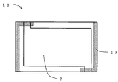
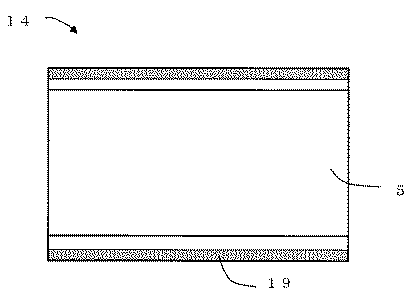
FIG. 1 is a plan view showing an upper surface of a first plate in the fuel cell separator according to the first embodiment of the present invention, and FIG. 2 is a bottom view showing a lower surface of the first plate in FIG. 3 is a plan view showing the upper surface of the second plate in the fuel cell separator according to the first embodiment, and FIG. 4 is a bottom view showing the lower surface of the second plate in FIG. Further, FIG. 5 is a partial sectional elevation view of the fuel cell stack according to the first embodiment of the present invention, and FIG. 6 is a plan sectional view of the fuel cell according to the first embodiment.
図5に示すように、この実施形態に係る燃料電池では、プロトン伝導性を有する固体高分子電解質膜3をはさんで、燃料極1および酸化剤極2を配置する。燃料極1および酸化剤極2の外側をさらにセパレータ4ではさんでいる。セパレータ4は、酸化剤極2に隣接する第1のプレート13と、燃料極1に隣接する第2のプレート14とからなる。固体高分子電解質膜3、燃料極1、酸化剤極2、第1のプレート13および第2のプレート14で一つの単位電池40が構成されていて、複数の単位電池40が積層されて燃料電池積層体11を構成している。
As shown in FIG. 5, in the fuel cell according to this embodiment, the
第1のプレート13の酸化剤極2に隣接する位置に酸化剤ガス流路6が形成され、第2のプレート14の燃料極1に隣接する位置に燃料ガス流路5が形成されている。さらに、第1のプレート13の第2のプレートに隣接する位置に冷却水流路7が形成されている。また、第1のプレート13の酸化剤ガス流路6と同じ面上に、端部シールシート固定用段差15が形成されている。
An oxidant
図6に示すように、燃料電池積層体11の側面に、積層方向に延びる6個のマニホールドが形成されていて、それぞれが各単位電池の特定のガス流路または冷却水流路に連絡している。 As shown in FIG. 6, six manifolds extending in the stacking direction are formed on the side surface of the fuel cell stack 11, and each manifold communicates with a specific gas flow path or cooling water flow path of each unit cell. .
すなわち、燃料ガス供給マニホールド8aは燃料ガス流路5に連絡し、ここから水素を含む燃料ガスが供給される。燃料ガス排出マニホールド8bは燃料ガス供給マニホールド8aの反対側に配置されて、燃料ガス流路5に連絡し、ここから燃料ガスが排出される。酸化剤ガス供給マニホールド9aは酸化剤ガス流路6に連絡し、ここから酸素を含む酸化剤ガスが供給される。酸化剤ガス排出マニホールド9bは酸化剤ガス供給マニホールド9aの反対側に配置されて、酸化剤ガス流路6に連絡し、ここから酸化剤ガスが排出される。冷却水供給マニホールド10aは冷却水流路7に連絡し、ここから冷却媒体(冷却水)が供給される。冷却水排出マニホールド10bは冷却水供給マニホールド10aの反対側に配置されて、冷却水流路7に連絡し、ここから冷却媒体が排出される。
That is, the fuel gas supply manifold 8a communicates with the fuel
電池反応によって燃料ガス中の水素と酸化剤ガス中の酸素が消費され、反応生成物の水が水蒸気として排出される。 The battery reaction consumes hydrogen in the fuel gas and oxygen in the oxidant gas, and the reaction product water is discharged as water vapor.
セパレータ4は、単位電池発電に伴う発熱を除去するための冷却除熱機能、単位電池を電気的に直列に接続するための導電機能、および、セパレータを介して互いに隣接する単位電池の燃料ガスと酸化剤ガスの混合を防止する反応ガス遮断機能を有している。また、所定の積層締付下で形状を保持できる機械的強度も有している。
The
セパレータ4の材質は、たとえば、炭素質あるいは黒鉛質炭素材料を主成分とする。炭素質あるいは黒鉛質を主体とするセパレータ4は、それらの粉体粒子を接着・結着する機能を有する樹脂で固着し、プレート化して用いてもよい。接着・結着機能を有する樹脂としては、フェノール樹脂、エポキシ樹脂に代表される熱硬化性樹脂、またはポリフェニレン樹脂に代表される熱可塑性樹脂を用いることができる。耐久性向上、電気導電性向上を目的として上記プレートを高温処理(炭化処理あるいは黒鉛化処理)してもよい。この炭素質あるいは黒鉛質を主体とするセパレータ4は、そのコストおよび物性の信頼性レベルの面から、熱硬化性樹脂を接着・結着剤とし、炭素質あるいは黒鉛質粉体の混合・混練した材料を熱間加圧成形したプレートから形成してもよい。
The material of the
この実施形態におけるセパレータ4は、反応ガスおよび冷却水に対して不浸透性を有する緻密質セパレータである。
The
図1、図2、図4にそれぞれ示すように、第1のプレート13の上面に酸化剤ガス流路6が形成され、第1のプレート13の下面に冷却水流路7が形成され、第2のプレート14の下面に燃料ガス流路5が形成されている。これらの流路5、6、7はプレート13、14の表面に形成された多数の平行溝として形成されている。ただし、図1、図2、図4では、各溝の図示は省略している。
As shown in FIGS. 1, 2, and 4, the oxidant
図1ないし図4において、網掛けして示す部分は、各プレート13、14の高密度領域19を示している。高密度領域19は各プレート13、14の表裏共通の位置にある。高密度領域19は、電池の積層した際に積層体11とマニホールド8a、8b、9a、9b、10a、10bのシール部が接する範囲であり、また図1についてはシールシートが固定される範囲でもある。
In FIG. 1 to FIG. 4, shaded portions indicate the
発明者らは、本実施形態の具体的実施例として、セパレータ4を成形する溝付金型を製作し、セパレータ4製作時には、密度の大きい領域19に成型品の体積見合いに対して1.2倍量の原材料を投入した。また、比較例として、従来セパレータの製作時は成型品の体積に見合った量の原材料を全面に投入した。表1に示す組成を持つ成形材料を用い成形試験を実施した。成形温度は170℃、加圧圧力は15MPa、加圧時間は5分、後硬化処理は200℃で6時間実施した。
第1のプレート(空気溝/冷却水溝付セパレータ)13と第2のプレート(燃料溝付セパレータ)14を接着剤とを用い、一体化しセパレータ4を製作した。一体化したセパレータ4と電極を交互に複数枚積層してスタック11を製作し、スタック11の側面4面にマニホールドを取り付けた。冷却水系統に冷却水を通水し、加圧して水の反応ガス側へのリークを調査した。その結果を表2に示す。
表2に示すように、従来方式では、50kPa以下でマニホールのシール材とセパレータ間の隙間から水のリークが確認された。リーク試験後にスタックを分解してリーク部を確認したところ、端部の欠けや巣状の欠陥が見られた。またリーク箇所とは異なるが、端部シールシート固定用段差15の一部に亀裂が見つかった。セパレータの密度は1.85〜1.95g/cm3の範囲で、特にリークが見られたり亀裂がある箇所の密度は他の箇所と比較して相対的に小さかった。
As shown in Table 2, in the conventional method, water leakage was confirmed from the gap between the sealing material of the manifold and the separator at 50 kPa or less. When the stack was disassembled after the leak test and the leak portion was confirmed, chipped edges and nest-like defects were found. Further, although different from the leaked portion, a crack was found in a part of the end seal
一方、本実施形態のセパレータにおいては50kPaの加圧でもリークは観察されなかった。リーク試験後にセパレータの密度を確認したところ密度が大きい範囲は1.97〜2.00g/cm3であるのに対し、他の箇所は1.93〜1.97g/cm3の範囲であった。 On the other hand, in the separator of this embodiment, no leak was observed even at a pressure of 50 kPa. When the density of the separator was confirmed after the leak test, the range in which the density was large was 1.97 to 2.00 g / cm 3 , while the other portions were in the range of 1.93 to 1.97 g / cm 3 . .
以上の結果から、本実施形態による直接溝付セパレータは従来の直接溝付セパレータに比して優れた効果を有していることがわかる。 From the above results, it can be seen that the direct grooved separator according to the present embodiment has an excellent effect as compared with the conventional direct grooved separator.
[第2の実施形態]
本発明の第2の実施形態に係るセパレータは、反応ガスの加湿機能と単位電池内凝縮生成水除去機能を持つ多孔質セパレータである。
[Second Embodiment]
The separator according to the second embodiment of the present invention is a porous separator having a function of humidifying reaction gas and a function of removing condensed product water in the unit cell.
第1の実施形態に係る図1ないし図6は第2の実施形態でも共通である。ただし、本実施形態では、図1ないし図4の高密度領域19は、気孔率の小さい領域として実現されている。
1 to 6 according to the first embodiment are common to the second embodiment. However, in the present embodiment, the high-
発明者らは、本実施形態の具体的実施例として、セパレータを成形する溝付金型を製作し、セパレータ4製作時には、気孔率の小さい高密度領域19に成型品の体積見合いに対して1.1倍量の原材料を投入した。また、比較例として、従来セパレータの製作時は成型品の体積に見合った量の原材料を全面に投入した。表1の組成を持つ成形材料を用い成形試験を実施した。成形温度は170℃、加圧圧力は3MPa、加圧時間は10分、後硬化処理は200℃で10時間実施した。
As a specific example of the present embodiment, the inventors manufactured a grooved mold for molding a separator. When the
第1のプレート(空気溝/冷却水溝付セパレータ)13と第2のプレート(燃料溝付セパレータ)14を製作した。これらのプレートを水中に水没させて減圧を5回繰り返し、プレート基材中に水を完全含浸して泡出圧試験を実施した。加圧は冷却水側から窒素を用いて行なった。その結果を表3に示す。
表3に示すように、従来方式ではアノードのガス流通路溝のない箇所が30kPa以下の泡出圧でウェットシールが破壊し泡が観察されたが、本実施形態では50kPa以上の泡出圧を持つことが示された。 As shown in Table 3, in the conventional system, the wet seal was broken and bubbles were observed at a bubble-free pressure of 30 kPa or less in the portion without the gas flow passage groove of the anode, but in this embodiment, a bubble-jet pressure of 50 kPa or more was observed. It was shown to have.
また一体化したセパレータ4と電極を交互に福数枚積層してスタック11を製作し、スタック4の側面4面にマニホールドを取り付けた。冷却水系統に冷却水を通水し、加圧して水の反応ガス側へのリークを調査した。その結果を表4に示す。
表4に示すように、従来方式では、50kPa以下でマニホールのシール材とセパレータ間の隙間から水のリークが確認された。リーク試験後にスタックを分解してリーク部を確認したところ、端部の欠けや巣状の欠陥が見られた。セパレータの気孔率は20〜35%の範囲で、特にリークが見られたり亀裂がある箇所の気孔率は他の箇所と比較して相対的に大きかった。一方、本実施形態のセパレータにおいては50kPaの加圧でもリークは観察されなかった。リーク試験後にセパレータの気孔率を確認したところ気孔率の小さい範囲は15〜20%であるのに対し、他の箇所は20〜25%の範囲であった。 As shown in Table 4, in the conventional method, water leakage was confirmed from the gap between the sealing material of the manifold and the separator at 50 kPa or less. When the stack was disassembled after the leak test and the leak portion was confirmed, chipped edges and nest-like defects were found. The porosity of the separator was in the range of 20 to 35%, and the porosity in particular where leaks were observed or cracked was relatively large compared to other locations. On the other hand, in the separator of this embodiment, no leak was observed even at a pressure of 50 kPa. When the porosity of the separator was confirmed after the leak test, the small range of the porosity was 15 to 20%, while the other portions were in the range of 20 to 25%.
以上の結果から、本実施形態による直接溝付セパレータは従来の直接溝付セパレータに比して優れた効果を有していることがわかる。 From the above results, it can be seen that the direct grooved separator according to the present embodiment has an excellent effect as compared with the conventional direct grooved separator.
気孔率の小さい領域では成型時に過度に圧力がかかるため、気孔率の大きい領域における成型圧力に影響を与えるので、材料の投入量や成型圧力の制御が重要である。 Since an excessive pressure is applied at the time of molding in a region with a low porosity, it affects the molding pressure in a region with a high porosity, and therefore, control of the amount of material input and the molding pressure is important.
本実施形態では気孔率を小さくする手段として原材料の投入量を多くする方法を採用したが、気孔率を小さくすることができるなら、この方法に限定されないことは言うまでもない。たとえば、事前に気孔率の小さい小片を製作しておき、成型時に小片を必要箇所に設置した上で原材料と共に成型する方法なども同様な効果が得られる。また、本実施形態におけるセパレータは、炭素質あるいは黒鉛質粉体を主成分とし、接着・結着材として熱硬化性樹脂または熱可塑性樹脂を含む材料を熱間・加圧成形して製造し、且つセパレータ溝を形成する溝付金型を成形金型として用いて製造するものであるが、熱間・加圧成形の代わりに射出成形されたセパレータについても同様の効果が得られることは言うまでもない。 In the present embodiment, a method of increasing the input amount of raw materials is adopted as a means for reducing the porosity, but it goes without saying that the method is not limited to this method as long as the porosity can be reduced. For example, the same effect can be obtained by a method in which a small piece having a low porosity is manufactured in advance, and the small piece is placed at a necessary position at the time of molding and then molded together with raw materials. Further, the separator in the present embodiment is produced by hot-pressing a material containing carbonaceous or graphite powder as a main component and containing a thermosetting resin or a thermoplastic resin as an adhesive / binder, In addition, a grooved mold for forming a separator groove is used as a molding mold, but it goes without saying that the same effect can be obtained for a separator formed by injection molding instead of hot / pressure molding. .
[第3の実施形態]
図7は本発明の第3の実施形態に係る燃料電池用セパレータにおける第1のプレートの上面を示す平面図であり、図8は図7の第1のプレートの下面を示す底面図である。また、図9は第3の実施形態に係る燃料電池用セパレータにおける第2のプレートの上面を示す平面図であり、図10は図9の第2のプレートの下面を示す底面図である。本発明の第1の実施形態に係る燃料電池を示す図5および図6は第3の実施形態に係る燃料電池にも共通である。
[Third Embodiment]
FIG. 7 is a plan view showing the upper surface of the first plate in the fuel cell separator according to the third embodiment of the present invention, and FIG. 8 is a bottom view showing the lower surface of the first plate in FIG. FIG. 9 is a plan view showing the top surface of the second plate in the fuel cell separator according to the third embodiment, and FIG. 10 is a bottom view showing the bottom surface of the second plate in FIG. 5 and 6 showing the fuel cell according to the first embodiment of the present invention are common to the fuel cell according to the third embodiment.
第3の実施形態は第2の実施形態の変形であって、気孔率の小さい高密度領域19を必要最小限としたものである。
The third embodiment is a modification of the second embodiment in which the high-
図7ないし図10には、第1のプレート13および第2のプレート14を示すとともに、セパレータ4を複数枚積層した後に各単位電池40にガスを供給するための各マニホールドを装着する位置を点線で示す。この実施形態では、各マニホールド8a、8b、9a、9b、10a、10bの壁に接するシール面に当たる位置のみに限定して気孔率が小さい高密度領域19が形成されている。このように高密度領域19を配置することにより、高密度領域19を最小限とすることができる。しかも、セパレータの欠陥によるリークを防止することができる。
7 to 10 show the
[他の実施形態]
以上説明した各実施形態は単なる例示であって、本発明はこれらに限定されるものではない。
[Other Embodiments]
Each embodiment described above is merely an example, and the present invention is not limited thereto.
たとえば、上記実施形態ではセパレータ周囲部の一部分に高密度領域を設けたが、周囲部全体を高密度領域としても同様の効果が得られる。 For example, in the above embodiment, the high density region is provided in a part of the periphery of the separator, but the same effect can be obtained even if the entire periphery is made a high density region.
また、第1の実施形態では密度を大きくする手段として原材料の投入量を多くする方法を採用したが、密度を大きくすることができるなら、この方法に限定されないことは言うまでもない。たとえば事前に密度の大きい小片を製作しておき、成型時に小片を必要箇所に設置した上で原材料と共に成型する方法なども同様な効果が得られる。 In the first embodiment, a method of increasing the input amount of raw materials is adopted as a means for increasing the density. However, it is needless to say that the method is not limited to this method as long as the density can be increased. For example, a similar effect can be obtained by manufacturing a small piece of high density in advance and placing the small piece in a necessary place at the time of molding together with the raw material.
第3の実施形態は第2の実施形態の変形として、特定位置のみに限定して気孔率が小さい高密度領域19を配置することとしたが、第1の実施形態の変形として、反応ガスおよび冷却水に対して不浸透性を有する緻密質セパレータにおいて、同様の特定位置のみに限定して高密度領域19を配置してもよい。
In the third embodiment, as a modification of the second embodiment, the high-
なお、上記説明で、説明の便宜上、「上」「下」の表現を用いたが、燃料電池積層体11およびセパレータをどのような向きに配置してもよく、上下逆でもよい。 In the above description, for convenience of description, the expressions “upper” and “lower” are used. However, the fuel cell stack 11 and the separator may be arranged in any orientation, and may be upside down.
さらに、上記実施形態では、第1のプレート13の表裏に酸化剤ガス流路6および冷却水流路7を形成し、第2のプレート14に燃料ガス流路5を形成することとしたが、他の例として、1枚のプレートの表裏に燃料ガス流路と冷却水流路を形成し、他のプレートには酸化剤ガス流路のみを形成するようにしてもよい。
Furthermore, in the above embodiment, the oxidant
1:燃料極(アノード極)
2:酸化剤極(カソード極)
3:固体高分子電解質膜
4:セパレータ
5:燃料ガス流路
6:酸化剤ガス流路
7:冷却水流路
8a:燃料ガス供給マニホールド
8b:燃料ガス排出マニホールド
9a:酸化剤ガス供給マニホールド
9b:酸化剤ガス排出マニホールド
10a:冷却水供給マニホールド
10b:冷却水排出マニホールド
11:燃料電池積層体(スタック)
13:第1のプレート
14:第2のプレート
15:端部シールシート固定用段差
19:高密度領域
40:単位電池
1: Fuel electrode (anode electrode)
2: Oxidant electrode (cathode electrode)
3: Solid polymer electrolyte membrane 4: Separator 5: Fuel gas channel 6: Oxidant gas channel 7: Coolant water channel 8a: Fuel gas supply manifold 8b: Fuel gas discharge manifold 9a: Oxidant gas supply manifold 9b: Oxidation Agent gas discharge manifold 10a: Cooling water supply manifold 10b: Cooling water discharge manifold 11: Fuel cell stack (stack)
13: First plate 14: Second plate 15: End seal sheet fixing step 19: High density region 40: Unit cell
Claims (5)
前記セパレータの周囲部の一部に配置されて気孔率が相対的に小さくて密度が相対的に大きい高密度領域と、前記セパレータのうちで前記高密度領域以外を形成して前記高密度領域に比べて気孔率が相対的に大きくて密度が相対的に小さい低密度領域と、を備え、
電解質としてプロトン伝導性を有する固体高分子電解質膜を用いた燃料電池で、前記燃料電池に供給される燃料ガスおよび酸化剤ガス流路の少なくとも一方に水蒸気を添加する機能を有する内部加湿方式に用いられる多孔質セパレータであり、
複数の単位電池を積層して積層体を形成し、その積層体の側面外側に、前記燃料ガス流路および酸化剤ガス流路それぞれに連通するために積層方向に延びる複数のガスマニホールドを配置する燃料電池に用いられるセパレータであって、
前記セパレータの周囲部のうちで前記ガスマニホールドの壁に接する部分のみが、前記高密度領域になっていることを特徴とする燃料電池用セパレータ。 At least one of a fuel gas flow path and an oxidant gas flow path is formed, and a uniform material including a thermosetting resin or a thermoplastic resin as a bonding / binding material mainly composed of carbonaceous or graphite powder is used. In the produced porous fuel cell separator,
A high density region that is disposed in a part of the periphery of the separator and has a relatively small porosity and a relatively large density, and the separator other than the high density region is formed in the high density region. compared Bei example and density is relatively small low-density region porosity is relatively large, the, the
In a fuel cell using a solid polymer electrolyte membrane having proton conductivity as an electrolyte, used for an internal humidification system having a function of adding water vapor to at least one of a fuel gas and an oxidant gas flow path supplied to the fuel cell A porous separator,
A plurality of unit cells are stacked to form a stacked body, and a plurality of gas manifolds extending in the stacking direction are disposed outside the side surfaces of the stacked body so as to communicate with the fuel gas flow path and the oxidant gas flow path, respectively. A separator used in a fuel cell,
Only the part which touches the wall of the said gas manifold among the peripheral parts of the said separator is the said high-density area | region, The separator for fuel cells characterized by the above-mentioned .
前記セパレータの周囲部のうちで前記冷却水マニホールドの壁に接する部分が、前記密度が相対的に大きい高密度領域になっていることを特徴とする請求項2に記載の燃料電池用セパレータ。 A separator used in a fuel cell in which a plurality of unit cells are stacked to form a stacked body, and a cooling water manifold extending in the stacking direction to communicate with the cooling water flow path is disposed outside the side surface of the stacked body. And
3. The fuel cell separator according to claim 2, wherein a portion of the peripheral portion of the separator that is in contact with a wall of the cooling water manifold is a high-density region in which the density is relatively high .
前記セパレータの周囲部のうちで前記ガスマニホールドの壁に接する部分のみが、他の部分に比べて気孔率が相対的に大きくて密度が相対的に大きく、 Of the peripheral part of the separator, only the part in contact with the wall of the gas manifold has a relatively large porosity and a relatively large density compared to other parts,
前記燃料ガス流路および酸化剤ガス流路の少なくとも一方に水蒸気を添加する機能を有すること、 Having a function of adding water vapor to at least one of the fuel gas channel and the oxidant gas channel;
を特徴とする燃料電池。 A fuel cell.
前記積層体の側面外側に、前記冷却水流路に連通するために積層方向に延びる複数の冷却水マニホールドが配置され、 A plurality of cooling water manifolds extending in the laminating direction to communicate with the cooling water flow path are disposed outside the side surface of the laminated body,
前記セパレータの周囲部のうちで前記冷却水マニホールドの壁に接する部分の密度が他の部分よりも相対的に大きいこと、 The density of the part in contact with the wall of the cooling water manifold in the peripheral part of the separator is relatively larger than other parts,
を特徴とする請求項4に記載の燃料電池。 The fuel cell according to claim 4.
Priority Applications (1)
| Application Number | Priority Date | Filing Date | Title |
|---|---|---|---|
| JP2007318106A JP5295554B2 (en) | 2007-12-10 | 2007-12-10 | Fuel cell and fuel cell separator |
Applications Claiming Priority (1)
| Application Number | Priority Date | Filing Date | Title |
|---|---|---|---|
| JP2007318106A JP5295554B2 (en) | 2007-12-10 | 2007-12-10 | Fuel cell and fuel cell separator |
Publications (2)
| Publication Number | Publication Date |
|---|---|
| JP2009140849A JP2009140849A (en) | 2009-06-25 |
| JP5295554B2 true JP5295554B2 (en) | 2013-09-18 |
Family
ID=40871260
Family Applications (1)
| Application Number | Title | Priority Date | Filing Date |
|---|---|---|---|
| JP2007318106A Active JP5295554B2 (en) | 2007-12-10 | 2007-12-10 | Fuel cell and fuel cell separator |
Country Status (1)
| Country | Link |
|---|---|
| JP (1) | JP5295554B2 (en) |
Cited By (1)
| Publication number | Priority date | Publication date | Assignee | Title |
|---|---|---|---|---|
| US11139499B2 (en) | 2018-06-01 | 2021-10-05 | Hyundai Motor Company | Manufacturing apparatus of membrane electrode assembly with excellent mass transfer characteristics and durability, and manufacturing method using the same |
Families Citing this family (3)
| Publication number | Priority date | Publication date | Assignee | Title |
|---|---|---|---|---|
| JP5520104B2 (en) * | 2010-03-26 | 2014-06-11 | パナソニック株式会社 | Manufacturing method of fuel cell separator |
| JP5693948B2 (en) * | 2010-12-27 | 2015-04-01 | ダイハツ工業株式会社 | Fuel cell inspection method and fuel cell inspection device |
| JP2016219359A (en) * | 2015-05-26 | 2016-12-22 | パナソニックIpマネジメント株式会社 | Fuel cell separator and fuel cell |
Family Cites Families (16)
| Publication number | Priority date | Publication date | Assignee | Title |
|---|---|---|---|---|
| JPS60136058U (en) * | 1984-02-22 | 1985-09-10 | 三菱鉛筆株式会社 | Structure of fuel cell components |
| US4588661A (en) * | 1984-08-27 | 1986-05-13 | Engelhard Corporation | Fabrication of gas impervious edge seal for a bipolar gas distribution assembly for use in a fuel cell |
| JPS62211868A (en) * | 1986-03-12 | 1987-09-17 | Fuji Electric Co Ltd | Gas separating plate for fuel cell |
| US4824741A (en) * | 1988-02-12 | 1989-04-25 | International Fuel Cells Corporation | Solid polymer electrolyte fuel cell system with porous plate evaporative cooling |
| JPH03138865A (en) * | 1989-10-24 | 1991-06-13 | Hitachi Chem Co Ltd | Separator for fuel cell |
| JP2922132B2 (en) * | 1995-03-15 | 1999-07-19 | 株式会社東芝 | Polymer electrolyte fuel cell |
| JP2003086199A (en) * | 2001-09-10 | 2003-03-20 | Fuji Electric Co Ltd | Cooling plate for fuel cell stack |
| JP2004111304A (en) * | 2002-09-20 | 2004-04-08 | Nissan Motor Co Ltd | Fuel cell separator and method of manufacturing the same |
| JP4078966B2 (en) * | 2002-12-02 | 2008-04-23 | 住友金属工業株式会社 | Stainless steel for separator of polymer electrolyte fuel cell and polymer electrolyte fuel cell |
| JP2004281261A (en) * | 2003-03-17 | 2004-10-07 | Nippon Steel Chem Co Ltd | Fuel cell separator and method of manufacturing the same |
| JP2005142015A (en) * | 2003-11-06 | 2005-06-02 | Nissan Motor Co Ltd | Fuel cell |
| JP4633403B2 (en) * | 2004-08-23 | 2011-02-16 | 東芝燃料電池システム株式会社 | Fuel cell system and start / stop method thereof |
| JP4734880B2 (en) * | 2004-09-29 | 2011-07-27 | 日産自動車株式会社 | Fuel cell |
| JP4762578B2 (en) * | 2005-03-14 | 2011-08-31 | 東芝燃料電池システム株式会社 | Fuel cell |
| JP4959980B2 (en) * | 2005-12-28 | 2012-06-27 | 東芝燃料電池システム株式会社 | Fuel cell |
| JP5179721B2 (en) * | 2006-01-10 | 2013-04-10 | 東芝燃料電池システム株式会社 | Fuel cell separator |
-
2007
- 2007-12-10 JP JP2007318106A patent/JP5295554B2/en active Active
Cited By (1)
| Publication number | Priority date | Publication date | Assignee | Title |
|---|---|---|---|---|
| US11139499B2 (en) | 2018-06-01 | 2021-10-05 | Hyundai Motor Company | Manufacturing apparatus of membrane electrode assembly with excellent mass transfer characteristics and durability, and manufacturing method using the same |
Also Published As
| Publication number | Publication date |
|---|---|
| JP2009140849A (en) | 2009-06-25 |
Similar Documents
| Publication | Publication Date | Title |
|---|---|---|
| CN102257661B (en) | Gas diffusion layer and process for production thereof, and fuel cell | |
| US7833673B2 (en) | Solid polymer electrolytic fuel cell | |
| JP4305568B2 (en) | POLYMER ELECTROLYTE FUEL CELL AND FUEL CELL | |
| CN1274048C (en) | High-polymer electrolyte fuel cell | |
| US20110236786A1 (en) | Fuel cell | |
| US10326150B2 (en) | Fuel cell module, fuel cell stack, and method for producing fuel cell module | |
| CN101542798B (en) | Polymer electrolyte fuel cell and electrode/film/frame assembly manufacturing method | |
| US8329322B2 (en) | Electrode-membrane-frame assembly for polyelectrolyte fuel cell, manufacturing method therefor, and polyelectrolyte fuel cell | |
| US20110053030A1 (en) | Fuel Cell with Gas Diffusion Layer having Flow Channel and Manufacturing Method Thereof | |
| CN104769761B (en) | Battery module and fuel cell unit | |
| CN101103479A (en) | Stack for fuel cell and fuel cell | |
| US9147889B2 (en) | Composite separator for polymer electrolyte membrane fuel cell and method for manufacturing the same | |
| JP5295554B2 (en) | Fuel cell and fuel cell separator | |
| JP2004335453A (en) | Fuel cell, fuel cell, fuel cell power generation system, and method for manufacturing the same | |
| WO2008056778A1 (en) | Fuel cell and fuel cell manufacturing method | |
| US10930939B2 (en) | Manufacturing method for fuel cell separator | |
| KR100400434B1 (en) | Polymer electrolyte-type fuel cell having reliable sealing structure | |
| JP2003123801A (en) | Polymer electrolyte stacked fuel cell | |
| JP5179721B2 (en) | Fuel cell separator | |
| JP2004055458A (en) | Fuel cell manufacturing method | |
| JP2019139993A (en) | Fuel cell module and manufacturing method thereof | |
| JP2007172953A (en) | Fuel cell | |
| JP2009176490A (en) | Fuel cell and fuel cell separator | |
| JP2003151574A (en) | Fuel cell separator and method of manufacturing the same | |
| JP6389959B2 (en) | Fuel cell stack and fuel cell stack manufacturing method |
Legal Events
| Date | Code | Title | Description |
|---|---|---|---|
| A621 | Written request for application examination |
Free format text: JAPANESE INTERMEDIATE CODE: A621 Effective date: 20100311 |
|
| RD04 | Notification of resignation of power of attorney |
Free format text: JAPANESE INTERMEDIATE CODE: A7424 Effective date: 20110421 |
|
| A977 | Report on retrieval |
Free format text: JAPANESE INTERMEDIATE CODE: A971007 Effective date: 20121121 |
|
| A131 | Notification of reasons for refusal |
Free format text: JAPANESE INTERMEDIATE CODE: A131 Effective date: 20121218 |
|
| A521 | Written amendment |
Free format text: JAPANESE INTERMEDIATE CODE: A523 Effective date: 20130215 |
|
| TRDD | Decision of grant or rejection written | ||
| A01 | Written decision to grant a patent or to grant a registration (utility model) |
Free format text: JAPANESE INTERMEDIATE CODE: A01 Effective date: 20130521 |
|
| A61 | First payment of annual fees (during grant procedure) |
Free format text: JAPANESE INTERMEDIATE CODE: A61 Effective date: 20130612 |
|
| R150 | Certificate of patent or registration of utility model |
Ref document number: 5295554 Country of ref document: JP Free format text: JAPANESE INTERMEDIATE CODE: R150 Free format text: JAPANESE INTERMEDIATE CODE: R150 |
|
| S111 | Request for change of ownership or part of ownership |
Free format text: JAPANESE INTERMEDIATE CODE: R313115 |
|
| R350 | Written notification of registration of transfer |
Free format text: JAPANESE INTERMEDIATE CODE: R350 |
|
| S111 | Request for change of ownership or part of ownership |
Free format text: JAPANESE INTERMEDIATE CODE: R313115 Free format text: JAPANESE INTERMEDIATE CODE: R313114 |
|
| R350 | Written notification of registration of transfer |
Free format text: JAPANESE INTERMEDIATE CODE: R350 |