JP5292867B2 - Image forming apparatus - Google Patents
Image forming apparatus Download PDFInfo
- Publication number
- JP5292867B2 JP5292867B2 JP2008066591A JP2008066591A JP5292867B2 JP 5292867 B2 JP5292867 B2 JP 5292867B2 JP 2008066591 A JP2008066591 A JP 2008066591A JP 2008066591 A JP2008066591 A JP 2008066591A JP 5292867 B2 JP5292867 B2 JP 5292867B2
- Authority
- JP
- Japan
- Prior art keywords
- unit
- opening
- transfer body
- transfer
- body unit
- Prior art date
- Legal status (The legal status is an assumption and is not a legal conclusion. Google has not performed a legal analysis and makes no representation as to the accuracy of the status listed.)
- Expired - Fee Related
Links
Images


Landscapes
- Electrophotography Configuration And Component (AREA)
- Electrostatic Charge, Transfer And Separation In Electrography (AREA)
Abstract
Description
本発明は、画像形成装置に関する。 The present invention relates to an image forming apparatus.
画像形成装置としては、特許文献1〜4に開示されるように、カートリッジを固定等することにより、カートリッジを装置内に装着した状態で、装置内の部品が破損せずに装置の運搬を可能とする画像形成装置が公知である。 As disclosed in Patent Documents 1 to 4, as an image forming apparatus, by fixing the cartridge or the like, the apparatus can be transported without damaging the components in the apparatus with the cartridge mounted in the apparatus. An image forming apparatus is known.
特許文献1に開示される画像形成装置は、押さえ部材によりカートリッジをガイド基準面に押圧し、カートリッジを装置内に装着した状態で装置を運搬する構成とされている。 The image forming apparatus disclosed in Patent Document 1 is configured to convey the apparatus in a state where the cartridge is pressed against the guide reference surface by a pressing member and the cartridge is mounted in the apparatus.
特許文献2に開示される画像形成装置は、固定部材によりカートリッジを装着する軌跡の途中で固定し、カートリッジを装置内に装着した状態で装置を運搬する構成とされている。
The image forming apparatus disclosed in
特許文献3に開示される画像形成装置は、カートリッジと装置本体の間に介在する規制部材によりカートリッジの移動を規制し、カートリッジを装置内に装着した状態で装置を運搬する構成とされている。 The image forming apparatus disclosed in Patent Document 3 is configured such that the movement of the cartridge is regulated by a regulating member interposed between the cartridge and the apparatus main body, and the apparatus is transported with the cartridge mounted in the apparatus.
特許文献4に開示される画像形成装置は、カートリッジを取り出さないと取り出すことのできない着脱部材によりカートリッジの移動を規制し、カートリッジを装置内に装着した状態で装置を運搬する構成とされている。
ところで、画像形成装置としては、記録媒体が搬送される搬送路を有する搬送路ユニットを実装する実装空間が形成された画像形成装置がある。このような装置においても、カートリッジを装置内に装着した状態で、装置内の部品が破損せずに、装置の運搬ができることが望まれる。 Incidentally, as an image forming apparatus, there is an image forming apparatus in which a mounting space for mounting a conveyance path unit having a conveyance path through which a recording medium is conveyed is formed. Even in such a device, it is desirable that the device can be transported without damage to the components in the device with the cartridge mounted in the device.
本発明は、実装空間に搬送路ユニットが装着されていない場合であっても、カートリッジを装置内に装着した状態で、装置内の部品が破損せずに、装置の運搬を可能とすることを課題とする。 The present invention makes it possible to transport the apparatus without damaging the components in the apparatus with the cartridge mounted in the apparatus even when the conveyance path unit is not mounted in the mounting space. Let it be an issue.
本発明の請求項1に係る画像形成装置は、装置本体に着脱可能に設けられ、感光体を含む感光体カートリッジと、前記感光体に接触して配置され、前記感光体に形成された画像を記録媒体に転写するための転写体ユニットと、前記転写体ユニットから見て前記感光体とは反対側に配置され、前記記録媒体が搬送される搬送路を有する搬送路ユニットを装着可能な実装空間と、前記実装空間を挟んで前記転写体ユニットに対向して前記装置本体に開閉可能に設けられ、開放されることで前記感光体カートリッジを取り出し可能にする開閉部と、前記開閉部または前記転写体ユニットに設けられ、前記転写体ユニットの移動を規制する規制部と、を備えている。 An image forming apparatus according to a first aspect of the present invention is detachably provided in an apparatus main body, and includes a photoconductor cartridge including a photoconductor and an image formed on the photoconductor, arranged in contact with the photoconductor. A mounting space in which a transfer unit for transferring to a recording medium and a transfer path unit that is disposed on the opposite side of the photoconductor from the transfer unit and has a transfer path for transferring the recording medium can be mounted. An opening / closing part that is openable and closable in the apparatus body so as to face the transfer body unit across the mounting space, and that can be taken out to open the photoreceptor cartridge, and the opening / closing part or the transfer A restricting portion that is provided in the body unit and restricts movement of the transfer body unit.
本発明の請求項1に係る画像形成装置は、さらに、前記開閉部または前記転写体ユニットに設けられ、前記搬送路ユニットに電源を供給するコネクタと、前記搬送路ユニットが実装されていない状態で前記コネクタを保護し、前記転写ユニットまたは前記開閉部に当って前記転写体ユニットの移動を規制する前記規制部としての保護体と、を備えている。 The image forming apparatus according to claim 1 of the present invention further includes a connector that is provided in the opening / closing part or the transfer body unit, and that supplies power to the transport path unit, and the transport path unit is not mounted. A protective body serving as the restricting portion that protects the connector and restricts movement of the transfer body unit against the transfer unit or the opening / closing portion.
本発明の請求項2に係る画像形成装置は、前記規制部が、前記開閉部または前記転写体ユニットに設けられ、前記搬送路ユニットが前記実装空間に装着された場合に前記搬送路ユニットを貫通して前記転写ユニットの移動を規制する突起である。
In the image forming apparatus according to
本発明の請求項1の構成によれば、本構成を有していない場合に比して、実装空間に搬送路ユニットが装着されていない場合であっても、カートリッジを装置内に装着した状態で、装置内の部品が破損せずに、装置の運搬が可能となる。 According to the configuration of claim 1 of the present invention, the cartridge is mounted in the apparatus even when the transport path unit is not mounted in the mounting space, as compared to the case where the configuration is not provided. Thus, the device can be transported without damaging the components in the device.
本発明の請求項1の構成によれば、本構成を有していない場合に比して、部品点数の低減ができる。また搬送路ユニットが実装空間に装着される場合に、保護体を除去するのを忘れる虞がない。 According to the configuration of the first aspect of the present invention, the number of parts can be reduced as compared with the case where the configuration is not provided. Further, when the transport path unit is mounted in the mounting space, there is no risk of forgetting to remove the protector.
本発明の請求項2の構成によれば、本構成を有していない場合に比して、搬送路ユニットが実装空間に装着される場合でも、規制部を除去する必要がなくなる。
According to the configuration of
以下に、本発明に係る実施形態の一例を図面に基づき説明する。
(本実施形態に係る画像形成装置の構成)
まず、本実施形態に係る画像形成装置の構成を説明する。図1は、本実施形態に係る画像形成装置の構成を示す概略図である。
Below, an example of an embodiment concerning the present invention is described based on a drawing.
(Configuration of image forming apparatus according to the present embodiment)
First, the configuration of the image forming apparatus according to the present embodiment will be described. FIG. 1 is a schematic diagram illustrating a configuration of an image forming apparatus according to the present embodiment.
本実施形態に係る画像形成装置10は、図1に示すように、装置本体12を備え、装置本体12の下部には、記録媒体の一例としての用紙Pが束状に積層されて収納される給紙トレイ14が配置されている。
As shown in FIG. 1, the
なお、記録媒体としては、用紙に限られず、プラスチックフィルム等のシート状部材、その他、画像が記録される媒体を用いても良い。 The recording medium is not limited to paper, and a sheet-like member such as a plastic film or other media on which an image is recorded may be used.
この給紙トレイ14の先端側(図1において右端側)の直上には、用紙Pの上面の先端側に接触して給紙トレイ14から用紙Pを送り出すピックアップロール16が配置されている。
A
また、装置本体12には、給紙トレイ14の先端部から延出して、緩やかに湾曲し、装置前方側(図1において右側)で上方へ向かって略垂直に延びる第1搬送路22が形成されている。
Further, the apparatus
この第1搬送路22に沿って、用紙搬送方向の上流側から順に、用紙Pを挟持搬送する複数(例えば、2つ)の搬送ロール対24、画像が形成される用紙Pを静電吸着して搬送する無端状の搬送ベルト26が配置されている。
Along the
搬送ベルト26は、上方に配置された巻掛ローラ27と、下方に配置された巻掛ローラ29に巻き掛けられており、巻掛ローラ27及び巻掛ローラ29のいずれかが、所定方向(図1において、時計回り方向)へ回転駆動することにより、搬送ベルト26が所定方向(図1において、時計回り方向)へ回転(循環駆動)する。
The
この搬送ベルト26の用紙搬送方向上流側には、搬送ベルト26の表面上を帯電させると共に、搬送ベルト26へ静電吸着される用紙Pを搬送ベルト26へ押し当てる帯電ロール31が搬送ベルト26に隣接して設けられている。
On the upstream side of the
また、第1搬送路22を間に挟んで、搬送ベルト26に対向する横方向には、感光体を含む感光体カートリッジの一例としてのプロセスカートリッジ28Y、28M、28C、28Kが、第1搬送路22に沿って、装置本体12に略垂直方向へ縦列配置されている。プロセスカートリッジ28Y、28M、28C、28Kは、イエロー、マゼンタ、シアン、ブラックの各色に対応しており、各色の画像が形成可能とされている。
Further, in the lateral direction facing the
各プロセスカートリッジ28Y、28M、28C、28Kには、それぞれ、所定方向(図1において反時計回り方向)へ回転する感光体ドラム30が設けられている。
Each
感光体ドラム30の周囲には、感光体ドラム30の回転方向上流側から順に、それぞれ、感光体ドラム30上を帯電させる帯電ローラ32と、帯電した感光体ドラム30を露光して感光体ドラム30上に静電潜像を形成する露光装置34と、感光体ドラム30上に形成された静電潜像へ各色のトナーを付着させて現像する現像ローラ36と、が設けられている。なお、帯電ローラ32及び現像ローラ36は、各プロセスカートリッジ28Y、28M、28C、28Kに、それぞれ、設けられている。
Around the
各プロセスカートリッジ28Y、28M、28C、28Kは、図2に示すように、横方向へ着脱可能とされている。各プロセスカートリッジ28Y、28M、28C、28Kを横方向へ着脱する構成としては、各プロセスカートリッジ28Y、28M、28C、28Kを横方向へ案内するガイド部材(図示省略)で支持し、このガイド部材に沿って各プロセスカートリッジ28Y、28M、28C、28Kの取り出し及び装着がなされる構成とすることができる。
As shown in FIG. 2, each
また、各プロセスカートリッジ28Y、28M、28C、28Kには、幅方向両端部に、着脱の際に把持する把手58が設けられている。なお、図1では、把手58を省略して図示している。
Further, each
感光体ドラム30に対向する横方向には、図1に示すように、搬送ベルト26の内周側に、それぞれ、感光体ドラム30上に形成されたトナー画像を用紙Pへ所定の転写位置で転写する転写装置38が設けられている。
As shown in FIG. 1, the toner images formed on the
搬送ベルト26より用紙搬送方向下流側には、転写されたトナー画像を用紙Pへ定着させる定着装置40、用紙Pを挟持搬送する搬送ロール対42、用紙Pを排出トレイ20へ排出する排出ロール対44が、この順で配置されている。
On the downstream side in the paper transport direction from the
また、片面に画像が形成された用紙Pを反転させて、再び第1搬送路22へ送り戻すための第2搬送路46が、搬送ベルト26を挟んで第1搬送路22に対向して形成されている。
Further, a
この第2搬送路46には、用紙Pを下方へ挟持搬送する複数(例えば、3つ)の搬送ロール対48が配置されており、両面に画像を形成する際には、片面に画像が形成された用紙Pは、排出ロール対44によりスイッチバックされて第2搬送路46に導かれ、複数の搬送ロール対48によって下方へ搬送され、第1搬送路22へ送り戻される。
A plurality (for example, three) of conveyance roller pairs 48 for nipping and conveying the paper P downward are arranged in the
次に、本実施形態に係る画像形成装置における、画像を形成する画像形成動作について説明する。 Next, an image forming operation for forming an image in the image forming apparatus according to the present embodiment will be described.
本実施形態に係る画像形成装置において、用紙Pへ画像を形成する場合は、まず給紙トレイ14から取り出された用紙Pが、複数の搬送ロール対24によって第1搬送路22を上方へ搬送され、搬送ベルト26へ送り込まれる。搬送ベルト26へ送り込まれた用紙Pは、帯電ロール31によって搬送ベルト26へ押し当てられると共に、帯電する搬送ベルト26に静電吸着されて、上方へ搬送され、イエロー、マゼンタ、シアン、ブラックの各色に対応した所定の転写位置へ順次送り込まれる。
In the image forming apparatus according to the present embodiment, when an image is formed on the paper P, the paper P taken out from the
所定の転写位置へ送り込まれた用紙Pは、感光体ドラム30上に形成された各色のトナー画像が転写装置38によって転写され、フルカラー画像が形成される。さらに定着装置40へ搬送され、転写されたトナー画像が定着装置40により定着される。
On the paper P sent to the predetermined transfer position, the toner images of the respective colors formed on the
用紙Pの片面へのみ画像を形成する場合は、トナー画像が定着された後、用紙Pは排出ロール対44により排出トレイ20へ排出される。
When an image is formed only on one side of the paper P, the paper P is discharged to the
用紙Pの両面へ画像を形成する場合には、片面に画像が形成された後、用紙Pは、排出ロール対44でスイッチバックされ、反転して第2搬送路46へ送り込まれる。さらに、第2搬送路46から再び第1搬送路22へ送り込まれ、画像が記録されていない反対面に、上記と同様に画像が形成され、用紙Pの両面へ画像が形成され、排出ロール対44により排出トレイ20へ排出される。以上のように、一連の画像形成動作が行われる。
When images are formed on both sides of the sheet P, after the image is formed on one side, the sheet P is switched back by the
次に、本実施形態の画像形成装置に係る開閉機構について説明する。 Next, the opening / closing mechanism according to the image forming apparatus of this embodiment will be described.
本実施形態に係る画像形成装置10の装置本体12の下部には、図2に示すように、装置本体12に開閉可能に設けられた開閉部の一例としての開閉カバー50が取り付けられている。
As shown in FIG. 2, an opening /
開閉カバー50は、装置本体12の下部に設けられた支持部61によって、装置本体12に回転可能に支持されている。開閉カバー50は、装置本体12側から装置外側へ(図2においてA方向へ)回転して、開位置へ傾倒することにより開放される。また、開閉カバー50は、開放された状態から装置本体12側へ(図2においてB方向へ)回転して、閉位置へ縦立することにより閉鎖される。
The opening /
開閉カバー50には、感光体ドラム30に形成された画像を用紙Pに転写するための転写体ユニット52が設けられている。この転写体ユニット52は、上述した転写装置38、搬送ベルト26及び帯電ロール31を備えている。
The opening /
転写体ユニット52は、開閉カバー50と一体に開閉されるようになっている。転写体ユニット52が装置本体12側から装置外側へ(図2においてA方向へ)回転して、開閉カバー50と共に開放されることより、図2に示すように、プロセスカートリッジ28Y、28M、28C、28Kなどの装置内部にある構成部品を着脱して、その構成部品を交換できる。また、第1搬送路22が開放され、第1搬送路22で生じたジャム(紙詰まり)を解消できる。
The
転写体ユニット52が閉鎖された状態においては、搬送ベルト26は、感光体ドラム30に接触する位置に配置される(図1及び図4参照)。
In a state where the
また、転写体ユニット52は、一端部が支持部53によって開閉カバー50に回転可能に支持されており、他端部が、支持部55によって開閉カバー50に着脱可能に支持されている。これにより、転写体ユニット52は、支持部55による支持状態を解除して支持部53を支点に回転させることにより、開閉カバー50に対して開閉可能とされている。
One end of the
なお、転写体ユニット52は、開閉カバー50ではなく、装置本体12に開閉可能に設けられる構成であってもよい。また、転写体ユニット52は、搬送ベルト26に替えて、転写ベルトを備える構成であってもよい。
Note that the
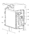
さらに、開閉カバー50には、図2、図4及び図5に示すように、第2搬送路46を有する搬送路ユニット54を装着可能な実装空間60が形成されている。
Further, as shown in FIGS. 2, 4, and 5, the opening /
この実装空間60は、開閉カバー50を閉鎖した状態において、転写体ユニット52から見て感光体ドラム30とは反対側であって、転写体ユニット52と開閉カバー50との間に配置される。換言すれば、開閉カバー50は、実装空間60を挟んで転写体ユニット52に対向して配置される。
The mounting
搬送路ユニット54は、開閉カバー50の上方(自由端側)から実装空間60へ挿入され、開閉カバー50に取り付けられて、図3に示すように、実装空間60に装着される。搬送路ユニット54には、複数(例えば、2つ)の搬送ロール対48が設けられている。
The
また、開閉カバー50には、図5に示すように、搬送路ユニット54に電源を供給するコネクタ63が設けられている。搬送路ユニット54が実装空間60に装着されることにより、接続操作することなく、搬送路ユニット54がコネクタ63と接続されるようになっている。
Further, the opening /
ここで、本実施形態に係る画像形成装置10は、図2、図4及び図5に示すように、開閉カバー50に設けられると共に転写体ユニット52の移動を規制する規制部の一例として、コネクタ63を保護する保護体56を備えている。
Here, as shown in FIGS. 2, 4, and 5, the
保護体56は、実装空間に搬送路ユニット54が装着されていない状態において、コネクタ63に装着されてコネクタ63を保護するようになっている。また、保護体56は、実装空間60に配置されており、保護体56を取り外さないと保護体56が邪魔をして搬送路ユニット54が装着できないようになっている。
The
保護体56は、側面視にて、実装空間を通って転写体ユニット52に達しており、開閉カバー50と転写体ユニット52との間に配置されている。
The
保護体56は、図6に示すように、コネクタ63を覆うカバー体と56Aと、カバー体56Aから転写体ユニット52へ突出した突出部56Bとを備えている。カバー体56Aには、コネクタ63に挿入される挿入片56Cが形成されている。
As shown in FIG. 6, the
突出部56Bは略直方体形状に形成されており、開閉カバー50に当る当て面57Aと転写体ユニット52に当る当て面57Bとを有している。当て面57Aが開閉カバー50の内壁に当ると共に、当て面57Bが転写体ユニット52のフレームに当ることにより、図4に示すように、転写体ユニット52が閉鎖された状態において、転写体ユニット52が開放される方向へ移動するのが規制される。
The protruding
このように、保護体56は、少なくとも、コネクタ63を保護する機能と、転写体ユニット52の移動を規制する機能との2つの機能とを有している。
As described above, the
保護体56は、転写体ユニット52の長手方向(図4及び図5のように転写体ユニット52が閉鎖された状態における上下方向)中間部に配置されており、転写体ユニット52の長手方向中間部に当たるようにされている。
The
本実施形態においては、保護体56は、転写体ユニット52の幅方向(図5におけるC方向)の一端部側に設けられている。なお、幅方向の両端部に設けられる構成であってもよい。
In the present embodiment, the
なお、コネクタ63及び保護体56は、開閉カバー50ではなく、転写体ユニット52側に設けられる構成であってもよい。保護体56が転写体ユニット52側に設けられる場合には、開閉カバー50に当って転写体ユニット52の移動を規制するように構成される。
The
(本実施形態の作用)
次に、上記の実施形態について作用を説明する。
(Operation of this embodiment)
Next, the operation of the above embodiment will be described.
本実施形態に係る画像形成装置10では、実装空間60に搬送路ユニット54が装着されず、プロセスカートリッジ28Y、28M、28C、28Kが装置本体12に装着されたまま、開閉カバー50及び転写体ユニット52が閉鎖され、画像形成装置10の運搬がなされる。
In the
このとき、実装空間60は搬送路ユニット54が装着されずに空洞となっているが、開閉カバー50に設けられた保護体56が、転写体ユニット52に当って転写体ユニット52の開放方向(開閉カバー50側)への移動を規制する。移動を規制された転写体ユニット52は、プロセスカートリッジ28Y、28M、28C、28Kに接触しており、プロセスカートリッジ28Y、28M、28C、28Kの取り出し方向への移動を規制する。
At this time, the mounting
これにより、装置本体12内部に設けられる構成部品としてのプロセスカートリッジ28Y、28M、28C、28K及び転写体ユニット52が、装置本体12内部で移動せず、構成部品同士の衝突が抑制される。
As a result, the
(転写体ユニットの移動を規制する規制部の変形例)
図7〜12は、変形例に係る構成を示す概略図である。
(Modification of the restricting part that restricts the movement of the transfer unit)
7 to 12 are schematic diagrams illustrating a configuration according to a modification.
変形例では、図7及び図8に示すように、転写体ユニットの移動を規制する規制部の一例として、搬送路ユニット54が実装空間60に装着された場合に搬送路ユニット54を貫通して転写体ユニット52の移動を規制する突起の一例としてのリブ62が、開閉カバー50に設けられている。なお、図7は、開閉カバー50に搬送路ユニット54が装着された状態を示し、図8は、開閉カバー50に搬送路ユニット54が装着されていない状態を示す。
In the modification, as shown in FIGS. 7 and 8, as an example of a restricting portion that restricts the movement of the transfer body unit, when the
リブ62には、転写体ユニット52に当る当て面62Aを有している。当て面62Aが転写体ユニット52のフレームに当ることにより、図9及び図10に示すように、転写体ユニット52が閉鎖された状態において、転写体ユニット52が開放される方向へ移動するのが規制される。なお、図9は、開閉カバー50に搬送路ユニット54が装着された状態を示し、図10は、開閉カバー50に搬送路ユニット54が装着されていない状態を示す。
The
搬送路ユニット54には、図11に示すように、リブ62が貫通する開口部64が形成されており、実装空間60に搬送路ユニット54が装着された場合においても、リブ62が搬送路ユニット54を貫通して、転写体ユニット52に当って転写体ユニット52の移動を規制する。
As shown in FIG. 11, the
また、変形例に係る構成においては、転写体ユニット52は、開閉カバー50と異なる位置で装置本体12に開閉可能に支持されており、図12に示すように、転写体ユニット52が開閉カバー50と共に開閉される際には、開閉カバー50に対して転写体ユニット52がズレながら開閉される。
Further, in the configuration according to the modification, the
リブ62には、開閉カバー50に対してズレながら開閉される転写体ユニット52が案内される案内面62Bが形成されている。
The
このように、リブ62は、少なくとも、転写体ユニット52を案内する機能と、転写体ユニット52の移動を規制する機能との2つの機能を有している
なお、リブ62は、開閉カバー50ではなく、転写体ユニット52側に設けられる構成であってもよい。 本発明は、上記の実施形態に限るものではなく、種々の変形、変更、改良が可能である。
As described above, the
10 画像形成装置
12 装置本体
28Y プロセスカートリッジ
30 感光体ドラム(感光体)
50 開閉カバー(開閉部)
52 転写体ユニット
54 搬送路ユニット
56 保護体(規制部)
60 実装空間
62 リブ(規制部)
63 コネクタ
DESCRIPTION OF
50 Opening / closing cover (opening / closing part)
52
60
63 connector
Claims (5)
前記感光体に接触して配置され、前記感光体に形成された画像を記録媒体に転写するための転写体ユニットと、
前記転写体ユニットから見て前記感光体とは反対側に配置され、前記記録媒体が搬送される搬送路を有する搬送路ユニットを装着可能な実装空間と、
前記実装空間を挟んで前記転写体ユニットに対向して前記装置本体に開閉可能に設けられ、開放されることで前記感光体カートリッジを取り出し可能にする開閉部と、
前記開閉部または前記転写体ユニットに設けられ、前記転写体ユニットの移動を規制する規制部と、
前記開閉部または前記転写体ユニットに設けられ、前記搬送路ユニットに電源を供給するコネクタと、
前記搬送路ユニットが実装されていない状態で前記コネクタを保護し、前記転写ユニットまたは前記開閉部に当って前記転写体ユニットの移動を規制する前記規制部としての保護体と、
を備えた画像形成装置。 A photoconductor cartridge that is detachably provided in the apparatus main body and includes a photoconductor;
A transfer unit that is disposed in contact with the photoconductor and transfers an image formed on the photoconductor to a recording medium;
A mounting space in which a transport path unit having a transport path on which the recording medium is transported can be mounted;
An opening / closing part provided in the apparatus main body so as to be openable and closable facing the transfer body unit across the mounting space, and allowing the photosensitive cartridge to be taken out by being opened;
A restriction portion that is provided in the opening / closing portion or the transfer body unit and restricts movement of the transfer body unit;
A connector provided in the opening / closing part or the transfer body unit, for supplying power to the transport path unit;
Protecting the connector in a state where the transport path unit is not mounted, and a protective body as the restricting portion that restricts movement of the transfer body unit against the transfer unit or the opening / closing portion;
An image forming apparatus.
前記感光体に接触して配置され、前記感光体に形成された画像を記録媒体に転写するための転写体ユニットと、
前記転写体ユニットから見て前記感光体とは反対側に配置され、前記記録媒体が搬送される搬送路を有する搬送路ユニットを装着可能な実装空間と、
前記実装空間を挟んで前記転写体ユニットに対向して前記装置本体に開閉可能に設けられ、開放されることで前記感光体カートリッジを取り出し可能にする開閉部と、
前記開閉部または前記転写体ユニットに設けられ、前記転写体ユニットの移動を規制する規制部と、
を備え、
前記規制部は、前記開閉部または前記転写体ユニットに設けられ、前記搬送路ユニットが前記実装空間に装着された場合に前記搬送路ユニットを貫通して前記転写ユニットの移動を規制する突起である画像形成装置。 A photoconductor cartridge that is detachably provided in the apparatus main body and includes a photoconductor;
A transfer unit that is disposed in contact with the photoconductor and transfers an image formed on the photoconductor to a recording medium;
A mounting space in which a transport path unit having a transport path on which the recording medium is transported can be mounted;
An opening / closing part provided in the apparatus main body so as to be openable and closable facing the transfer body unit across the mounting space, and allowing the photosensitive cartridge to be taken out by being opened;
A restriction portion that is provided in the opening / closing portion or the transfer body unit and restricts movement of the transfer body unit;
With
The restricting portion is a protrusion that is provided in the opening / closing portion or the transfer unit, and restricts movement of the transfer unit through the transport path unit when the transport path unit is mounted in the mounting space. Image forming apparatus.
前記突起には、前記開閉部に対してずれながら開閉される前記転写体ユニットが案内される案内面が形成されている請求項2に記載の画像形成装置。 The image forming apparatus according to claim 2, wherein a guide surface for guiding the transfer body unit that is opened and closed while being displaced with respect to the opening and closing unit is formed on the protrusion.
前記転写体ユニットの他端部を前記開閉部に対して支持して、前記開閉部に対する前記転写体ユニットの開閉を規制する支持部を備える請求項1〜4のいずれか1項に記載の画像形成装置。 5. The image according to claim 1, further comprising a support portion that supports the other end portion of the transfer body unit with respect to the opening and closing portion and restricts the opening and closing of the transfer body unit with respect to the opening and closing portion. Forming equipment.
Priority Applications (1)
| Application Number | Priority Date | Filing Date | Title |
|---|---|---|---|
| JP2008066591A JP5292867B2 (en) | 2008-03-14 | 2008-03-14 | Image forming apparatus |
Applications Claiming Priority (1)
| Application Number | Priority Date | Filing Date | Title |
|---|---|---|---|
| JP2008066591A JP5292867B2 (en) | 2008-03-14 | 2008-03-14 | Image forming apparatus |
Publications (2)
| Publication Number | Publication Date |
|---|---|
| JP2009222925A JP2009222925A (en) | 2009-10-01 |
| JP5292867B2 true JP5292867B2 (en) | 2013-09-18 |
Family
ID=41239782
Family Applications (1)
| Application Number | Title | Priority Date | Filing Date |
|---|---|---|---|
| JP2008066591A Expired - Fee Related JP5292867B2 (en) | 2008-03-14 | 2008-03-14 | Image forming apparatus |
Country Status (1)
| Country | Link |
|---|---|
| JP (1) | JP5292867B2 (en) |
Families Citing this family (1)
| Publication number | Priority date | Publication date | Assignee | Title |
|---|---|---|---|---|
| JP6317992B2 (en) * | 2013-05-14 | 2018-04-25 | 株式会社東芝 | Sheet processing apparatus and erasing apparatus |
Family Cites Families (10)
| Publication number | Priority date | Publication date | Assignee | Title |
|---|---|---|---|---|
| JPH025756U (en) * | 1988-06-23 | 1990-01-16 | ||
| JP3577308B2 (en) * | 2003-04-21 | 2004-10-13 | 株式会社リコー | Image forming apparatus |
| JP2005091708A (en) * | 2003-09-17 | 2005-04-07 | Canon Inc | Process cartridge and image forming apparatus |
| JP2006071671A (en) * | 2004-08-31 | 2006-03-16 | Canon Inc | Electrophotographic image forming apparatus and regulating member |
| JP4798992B2 (en) * | 2004-12-16 | 2011-10-19 | キヤノン株式会社 | Electrophotographic image forming apparatus |
| JP2006235265A (en) * | 2005-02-25 | 2006-09-07 | Canon Finetech Inc | Image forming apparatus and method for transporting the same |
| JP4577105B2 (en) * | 2005-06-13 | 2010-11-10 | 富士ゼロックス株式会社 | Image forming apparatus |
| JP4735073B2 (en) * | 2005-06-24 | 2011-07-27 | 富士ゼロックス株式会社 | Image forming apparatus |
| JP4929837B2 (en) * | 2006-05-19 | 2012-05-09 | 富士ゼロックス株式会社 | Image forming apparatus |
| JP4697154B2 (en) * | 2007-02-22 | 2011-06-08 | ブラザー工業株式会社 | Image forming apparatus |
-
2008
- 2008-03-14 JP JP2008066591A patent/JP5292867B2/en not_active Expired - Fee Related
Also Published As
| Publication number | Publication date |
|---|---|
| JP2009222925A (en) | 2009-10-01 |
Similar Documents
| Publication | Publication Date | Title |
|---|---|---|
| JP4677380B2 (en) | Case cover opening / closing mechanism | |
| JP4940750B2 (en) | Opening / closing mechanism of opening / closing part, image forming apparatus | |
| JP6210693B2 (en) | Image forming apparatus | |
| JP4490790B2 (en) | Image forming apparatus | |
| JP2011237685A (en) | Image forming apparatus | |
| JP5380871B2 (en) | Loading mechanism and image forming apparatus | |
| JP4941608B2 (en) | Opening / closing mechanism of opening / closing part, image forming apparatus | |
| JP5292867B2 (en) | Image forming apparatus | |
| JP5158186B2 (en) | Case cover opening / closing mechanism | |
| JP5638039B2 (en) | Image forming apparatus | |
| JP4552819B2 (en) | Image forming apparatus | |
| JP5447713B2 (en) | Loading mechanism and image forming apparatus | |
| WO2015111492A1 (en) | Image forming device | |
| JP2017003819A (en) | Image forming apparatus | |
| JP2006153973A (en) | Image forming apparatus | |
| CN213474818U (en) | Image processing apparatus | |
| JP4998343B2 (en) | Opening / closing mechanism and image forming apparatus | |
| JP2009184783A (en) | Paper feeding device and image forming device | |
| JP6451834B2 (en) | Image forming apparatus | |
| JP2017227713A (en) | Image forming apparatus | |
| JP4692099B2 (en) | Image forming apparatus and process cartridge | |
| JP2018095388A (en) | Sheet supporting apparatus and image forming apparatus | |
| JP2015064517A (en) | Image forming apparatus | |
| JP2016196355A (en) | Image forming apparatus | |
| JP6291980B2 (en) | Paper feed cassette and image forming apparatus |
Legal Events
| Date | Code | Title | Description |
|---|---|---|---|
| A621 | Written request for application examination |
Free format text: JAPANESE INTERMEDIATE CODE: A621 Effective date: 20110223 |
|
| A977 | Report on retrieval |
Free format text: JAPANESE INTERMEDIATE CODE: A971007 Effective date: 20120718 |
|
| A131 | Notification of reasons for refusal |
Free format text: JAPANESE INTERMEDIATE CODE: A131 Effective date: 20120724 |
|
| A521 | Written amendment |
Free format text: JAPANESE INTERMEDIATE CODE: A523 Effective date: 20120924 |
|
| A131 | Notification of reasons for refusal |
Free format text: JAPANESE INTERMEDIATE CODE: A131 Effective date: 20130108 |
|
| A521 | Written amendment |
Free format text: JAPANESE INTERMEDIATE CODE: A523 Effective date: 20130311 |
|
| TRDD | Decision of grant or rejection written | ||
| A01 | Written decision to grant a patent or to grant a registration (utility model) |
Free format text: JAPANESE INTERMEDIATE CODE: A01 Effective date: 20130514 |
|
| A61 | First payment of annual fees (during grant procedure) |
Free format text: JAPANESE INTERMEDIATE CODE: A61 Effective date: 20130527 |
|
| R150 | Certificate of patent or registration of utility model |
Ref document number: 5292867 Country of ref document: JP Free format text: JAPANESE INTERMEDIATE CODE: R150 Free format text: JAPANESE INTERMEDIATE CODE: R150 |
|
| LAPS | Cancellation because of no payment of annual fees |