JP5258774B2 - Wind power generator, generator for generating power from the atmosphere, and method for generating power from the moving atmosphere - Google Patents
Wind power generator, generator for generating power from the atmosphere, and method for generating power from the moving atmosphere Download PDFInfo
- Publication number
- JP5258774B2 JP5258774B2 JP2009533744A JP2009533744A JP5258774B2 JP 5258774 B2 JP5258774 B2 JP 5258774B2 JP 2009533744 A JP2009533744 A JP 2009533744A JP 2009533744 A JP2009533744 A JP 2009533744A JP 5258774 B2 JP5258774 B2 JP 5258774B2
- Authority
- JP
- Japan
- Prior art keywords
- wind turbine
- flow
- zone
- air
- flow path
- Prior art date
- Legal status (The legal status is an assumption and is not a legal conclusion. Google has not performed a legal analysis and makes no representation as to the accuracy of the status listed.)
- Expired - Fee Related
Links
- 238000000034 method Methods 0.000 title claims description 23
- 230000001133 acceleration Effects 0.000 claims abstract description 19
- 238000013461 design Methods 0.000 claims description 17
- 238000011144 upstream manufacturing Methods 0.000 claims description 16
- 238000005339 levitation Methods 0.000 claims description 12
- 239000007788 liquid Substances 0.000 claims description 6
- 238000010248 power generation Methods 0.000 claims description 4
- XLYOFNOQVPJJNP-UHFFFAOYSA-N water Substances O XLYOFNOQVPJJNP-UHFFFAOYSA-N 0.000 claims description 4
- 230000015572 biosynthetic process Effects 0.000 claims description 2
- 230000006835 compression Effects 0.000 claims description 2
- 238000007906 compression Methods 0.000 claims description 2
- 230000001914 calming effect Effects 0.000 claims 2
- 238000007599 discharging Methods 0.000 claims 1
- 238000004519 manufacturing process Methods 0.000 abstract description 3
- 230000005611 electricity Effects 0.000 abstract 1
- 230000000694 effects Effects 0.000 description 8
- 238000000605 extraction Methods 0.000 description 5
- 238000010586 diagram Methods 0.000 description 3
- 238000005457 optimization Methods 0.000 description 3
- 206010039897 Sedation Diseases 0.000 description 2
- 230000036280 sedation Effects 0.000 description 2
- 238000004804 winding Methods 0.000 description 2
- UFHFLCQGNIYNRP-UHFFFAOYSA-N Hydrogen Chemical compound [H][H] UFHFLCQGNIYNRP-UHFFFAOYSA-N 0.000 description 1
- 239000002551 biofuel Substances 0.000 description 1
- 238000006243 chemical reaction Methods 0.000 description 1
- 239000003245 coal Substances 0.000 description 1
- 238000010276 construction Methods 0.000 description 1
- 238000007796 conventional method Methods 0.000 description 1
- 238000011161 development Methods 0.000 description 1
- 238000005265 energy consumption Methods 0.000 description 1
- 230000007613 environmental effect Effects 0.000 description 1
- 230000005284 excitation Effects 0.000 description 1
- 239000002803 fossil fuel Substances 0.000 description 1
- 239000007789 gas Substances 0.000 description 1
- 239000001257 hydrogen Substances 0.000 description 1
- 229910052739 hydrogen Inorganic materials 0.000 description 1
- 230000006698 induction Effects 0.000 description 1
- 238000009434 installation Methods 0.000 description 1
- 230000002093 peripheral effect Effects 0.000 description 1
- 238000011160 research Methods 0.000 description 1
- 239000003351 stiffener Substances 0.000 description 1
Images


Classifications
-
- F—MECHANICAL ENGINEERING; LIGHTING; HEATING; WEAPONS; BLASTING
- F03—MACHINES OR ENGINES FOR LIQUIDS; WIND, SPRING, OR WEIGHT MOTORS; PRODUCING MECHANICAL POWER OR A REACTIVE PROPULSIVE THRUST, NOT OTHERWISE PROVIDED FOR
- F03D—WIND MOTORS
- F03D1/00—Wind motors with rotation axis substantially parallel to the air flow entering the rotor
- F03D1/04—Wind motors with rotation axis substantially parallel to the air flow entering the rotor having stationary wind-guiding means, e.g. with shrouds or channels
-
- F—MECHANICAL ENGINEERING; LIGHTING; HEATING; WEAPONS; BLASTING
- F03—MACHINES OR ENGINES FOR LIQUIDS; WIND, SPRING, OR WEIGHT MOTORS; PRODUCING MECHANICAL POWER OR A REACTIVE PROPULSIVE THRUST, NOT OTHERWISE PROVIDED FOR
- F03D—WIND MOTORS
- F03D13/00—Assembly, mounting or commissioning of wind motors; Arrangements specially adapted for transporting wind motor components
- F03D13/10—Assembly of wind motors; Arrangements for erecting wind motors
-
- F—MECHANICAL ENGINEERING; LIGHTING; HEATING; WEAPONS; BLASTING
- F03—MACHINES OR ENGINES FOR LIQUIDS; WIND, SPRING, OR WEIGHT MOTORS; PRODUCING MECHANICAL POWER OR A REACTIVE PROPULSIVE THRUST, NOT OTHERWISE PROVIDED FOR
- F03D—WIND MOTORS
- F03D15/00—Transmission of mechanical power
- F03D15/10—Transmission of mechanical power using gearing not limited to rotary motion, e.g. with oscillating or reciprocating members
-
- F—MECHANICAL ENGINEERING; LIGHTING; HEATING; WEAPONS; BLASTING
- F03—MACHINES OR ENGINES FOR LIQUIDS; WIND, SPRING, OR WEIGHT MOTORS; PRODUCING MECHANICAL POWER OR A REACTIVE PROPULSIVE THRUST, NOT OTHERWISE PROVIDED FOR
- F03D—WIND MOTORS
- F03D80/00—Details, components or accessories not provided for in groups F03D1/00 - F03D17/00
- F03D80/70—Bearing or lubricating arrangements
-
- F—MECHANICAL ENGINEERING; LIGHTING; HEATING; WEAPONS; BLASTING
- F05—INDEXING SCHEMES RELATING TO ENGINES OR PUMPS IN VARIOUS SUBCLASSES OF CLASSES F01-F04
- F05B—INDEXING SCHEME RELATING TO WIND, SPRING, WEIGHT, INERTIA OR LIKE MOTORS, TO MACHINES OR ENGINES FOR LIQUIDS COVERED BY SUBCLASSES F03B, F03D AND F03G
- F05B2220/00—Application
- F05B2220/70—Application in combination with
- F05B2220/706—Application in combination with an electrical generator
-
- F—MECHANICAL ENGINEERING; LIGHTING; HEATING; WEAPONS; BLASTING
- F05—INDEXING SCHEMES RELATING TO ENGINES OR PUMPS IN VARIOUS SUBCLASSES OF CLASSES F01-F04
- F05B—INDEXING SCHEME RELATING TO WIND, SPRING, WEIGHT, INERTIA OR LIKE MOTORS, TO MACHINES OR ENGINES FOR LIQUIDS COVERED BY SUBCLASSES F03B, F03D AND F03G
- F05B2240/00—Components
- F05B2240/10—Stators
- F05B2240/13—Stators to collect or cause flow towards or away from turbines
- F05B2240/131—Stators to collect or cause flow towards or away from turbines by means of vertical structures, i.e. chimneys
-
- F—MECHANICAL ENGINEERING; LIGHTING; HEATING; WEAPONS; BLASTING
- F05—INDEXING SCHEMES RELATING TO ENGINES OR PUMPS IN VARIOUS SUBCLASSES OF CLASSES F01-F04
- F05B—INDEXING SCHEME RELATING TO WIND, SPRING, WEIGHT, INERTIA OR LIKE MOTORS, TO MACHINES OR ENGINES FOR LIQUIDS COVERED BY SUBCLASSES F03B, F03D AND F03G
- F05B2240/00—Components
- F05B2240/10—Stators
- F05B2240/13—Stators to collect or cause flow towards or away from turbines
- F05B2240/133—Stators to collect or cause flow towards or away from turbines with a convergent-divergent guiding structure, e.g. a Venturi conduit
-
- F—MECHANICAL ENGINEERING; LIGHTING; HEATING; WEAPONS; BLASTING
- F05—INDEXING SCHEMES RELATING TO ENGINES OR PUMPS IN VARIOUS SUBCLASSES OF CLASSES F01-F04
- F05B—INDEXING SCHEME RELATING TO WIND, SPRING, WEIGHT, INERTIA OR LIKE MOTORS, TO MACHINES OR ENGINES FOR LIQUIDS COVERED BY SUBCLASSES F03B, F03D AND F03G
- F05B2240/00—Components
- F05B2240/40—Use of a multiplicity of similar components
-
- F—MECHANICAL ENGINEERING; LIGHTING; HEATING; WEAPONS; BLASTING
- F05—INDEXING SCHEMES RELATING TO ENGINES OR PUMPS IN VARIOUS SUBCLASSES OF CLASSES F01-F04
- F05B—INDEXING SCHEME RELATING TO WIND, SPRING, WEIGHT, INERTIA OR LIKE MOTORS, TO MACHINES OR ENGINES FOR LIQUIDS COVERED BY SUBCLASSES F03B, F03D AND F03G
- F05B2240/00—Components
- F05B2240/90—Mounting on supporting structures or systems
- F05B2240/91—Mounting on supporting structures or systems on a stationary structure
-
- F—MECHANICAL ENGINEERING; LIGHTING; HEATING; WEAPONS; BLASTING
- F05—INDEXING SCHEMES RELATING TO ENGINES OR PUMPS IN VARIOUS SUBCLASSES OF CLASSES F01-F04
- F05B—INDEXING SCHEME RELATING TO WIND, SPRING, WEIGHT, INERTIA OR LIKE MOTORS, TO MACHINES OR ENGINES FOR LIQUIDS COVERED BY SUBCLASSES F03B, F03D AND F03G
- F05B2260/00—Function
- F05B2260/40—Transmission of power
- F05B2260/403—Transmission of power through the shape of the drive components
- F05B2260/4031—Transmission of power through the shape of the drive components as in toothed gearing
-
- Y—GENERAL TAGGING OF NEW TECHNOLOGICAL DEVELOPMENTS; GENERAL TAGGING OF CROSS-SECTIONAL TECHNOLOGIES SPANNING OVER SEVERAL SECTIONS OF THE IPC; TECHNICAL SUBJECTS COVERED BY FORMER USPC CROSS-REFERENCE ART COLLECTIONS [XRACs] AND DIGESTS
- Y02—TECHNOLOGIES OR APPLICATIONS FOR MITIGATION OR ADAPTATION AGAINST CLIMATE CHANGE
- Y02E—REDUCTION OF GREENHOUSE GAS [GHG] EMISSIONS, RELATED TO ENERGY GENERATION, TRANSMISSION OR DISTRIBUTION
- Y02E10/00—Energy generation through renewable energy sources
- Y02E10/70—Wind energy
- Y02E10/72—Wind turbines with rotation axis in wind direction
-
- Y—GENERAL TAGGING OF NEW TECHNOLOGICAL DEVELOPMENTS; GENERAL TAGGING OF CROSS-SECTIONAL TECHNOLOGIES SPANNING OVER SEVERAL SECTIONS OF THE IPC; TECHNICAL SUBJECTS COVERED BY FORMER USPC CROSS-REFERENCE ART COLLECTIONS [XRACs] AND DIGESTS
- Y02—TECHNOLOGIES OR APPLICATIONS FOR MITIGATION OR ADAPTATION AGAINST CLIMATE CHANGE
- Y02E—REDUCTION OF GREENHOUSE GAS [GHG] EMISSIONS, RELATED TO ENERGY GENERATION, TRANSMISSION OR DISTRIBUTION
- Y02E10/00—Energy generation through renewable energy sources
- Y02E10/70—Wind energy
- Y02E10/728—Onshore wind turbines
-
- Y—GENERAL TAGGING OF NEW TECHNOLOGICAL DEVELOPMENTS; GENERAL TAGGING OF CROSS-SECTIONAL TECHNOLOGIES SPANNING OVER SEVERAL SECTIONS OF THE IPC; TECHNICAL SUBJECTS COVERED BY FORMER USPC CROSS-REFERENCE ART COLLECTIONS [XRACs] AND DIGESTS
- Y02—TECHNOLOGIES OR APPLICATIONS FOR MITIGATION OR ADAPTATION AGAINST CLIMATE CHANGE
- Y02P—CLIMATE CHANGE MITIGATION TECHNOLOGIES IN THE PRODUCTION OR PROCESSING OF GOODS
- Y02P70/00—Climate change mitigation technologies in the production process for final industrial or consumer products
- Y02P70/50—Manufacturing or production processes characterised by the final manufactured product
Landscapes
- Engineering & Computer Science (AREA)
- Life Sciences & Earth Sciences (AREA)
- Sustainable Development (AREA)
- Sustainable Energy (AREA)
- Chemical & Material Sciences (AREA)
- Combustion & Propulsion (AREA)
- Mechanical Engineering (AREA)
- General Engineering & Computer Science (AREA)
- Wind Motors (AREA)
- Connection Of Motors, Electrical Generators, Mechanical Devices, And The Like (AREA)
- Other Liquid Machine Or Engine Such As Wave Power Use (AREA)
Abstract
Description
本発明は、装置内を通過する大気を利用して電力を発生させるための風力発電装置に関する。本発明は、また、装置内を通過する大気を利用して電力を発生させるための風力発電装置システムに関する。 The present invention relates to a wind power generator for generating electric power using the atmosphere passing through the apparatus. The present invention also relates to a wind turbine generator system for generating electric power using the atmosphere passing through the apparatus.
本装置は、装置内を通過する大気を利用して電力を発生させるための発電機に関する、つまり、本発明による風力発電装置及びシステムにとりわけ好適な発電機に関する。
最後に、本発明は大気から電力を発生させるための方法に関する。
The present apparatus relates to a generator for generating electric power using the atmosphere passing through the apparatus, that is, a generator particularly suitable for the wind power generation apparatus and system according to the present invention.
Finally, the present invention relates to a method for generating power from the atmosphere.
何年もの間、再生可能エネルギーの使用を促進するための奨励政策の結果として、大いに、化石燃料についての問題を解決するためにかなりの研究がなされてきた。ここで挙げられる例としては、風エネルギー、熱力学的エネルギー、バイオ燃料、及び水素が含まれる。しかしながら、これらの努力にもかかわらず、原子力、ガス、及び石炭といった従来の形のエネルギー変換と経済的に競合しうるように、このような形のエネルギーを安く入手可能とすることはまだ可能ではない。 Over the years, considerable research has been done to solve the problem of fossil fuels as a result of incentive policies to promote the use of renewable energy. Examples mentioned here include wind energy, thermodynamic energy, biofuel, and hydrogen. However, despite these efforts, it is still not possible to make such forms of energy available cheaply so that they can economically compete with traditional forms of energy conversion such as nuclear power, gas, and coal. Absent.
風エネルギーの利用についてもかなりの投資がなされてきた。この投資は、単一の風車、さらには風力発電所の設置について、発展及び実現に貢献してきた。風車を利用して風エネルギーを変換させることは、特にこの種の風車又は風力発電所を開発、製造、及び建設する費用に対して、風エネルギーの生成量が極めて少ないという大きな不都合があった。また、環境面におけるかなりの不都合が存在することに加えて、この種の風力装置は、風が十分強い場合にのみ、また、風がこの目的のために十分に強力である場合にのみ、稼働可能であるという大きな不都合があった。不快な騒音が生じるだけでなく、極めて不愉快な振動下で、非常に不愉快な影及び/又は影をおとすこともある。風又は風の強度は常に変わるものであるから、エネルギーを常に、又は一定の水準で、発生させることも不可能である。 Considerable investment has been made in the use of wind energy. This investment has contributed to the development and realization of the installation of a single windmill and even a wind farm. Using wind turbines to convert wind energy has the major disadvantage of generating very little wind energy, especially for the cost of developing, manufacturing and building this type of wind turbine or wind power plant. Also, in addition to the considerable environmental disadvantages, this type of wind power device only works if the wind is strong enough and only if the wind is strong enough for this purpose. There was a major inconvenience that it was possible. Not only does it cause unpleasant noise, but it can also cast very unpleasant shadows and / or shadows under very unpleasant vibrations. Since the wind or wind intensity is always changing, it is also impossible to generate energy constantly or at a constant level.
さらに大きな不都合は、エネルギーが生成される装置ごとに、膨大な空間が必要とされることである。
本発明は、それゆえ、大気を利用して電力を発生させるための風力発電装置を作成するという目的に基づくものであり、該装置は、実質的に大気の優勢な風速とは独立して、最適な流速で稼働するものである。
An even greater disadvantage is the enormous space required for each device that generates energy.
The present invention is therefore based on the object of creating a wind power generator for generating power using the atmosphere, which is substantially independent of the dominant wind speed of the atmosphere, It operates at an optimal flow rate.
本発明は、また、風力発電装置システムを作成する目的に基づくものであって、該風力発電装置システムによって、それに対応する大量のエネルギーが生成される。
本発明は、さらに、発電機を作成する目的に基づくものであって、該発電機は、大気から電力を発生させるために設計が特に簡略かつ効率的なものである。
The present invention is also based on the object of creating a wind power generator system, which generates a large amount of energy corresponding thereto.
The present invention is further based on the purpose of creating a generator, which is particularly simple and efficient in design for generating power from the atmosphere.
最後に、本発明は、大気から電力を発生させるための方法を策定する目的に基づくものであって、該方法によって、効率的にかつ風の状況とは独立して、エネルギーを発生させることができる。 Finally, the present invention is based on the objective of developing a method for generating power from the atmosphere, which can generate energy efficiently and independently of wind conditions. it can.
本発明によれば、大気から電力を発生させるための風力発電装置(1)であって、該風力発電装置(1)は流路を備え、該流路を通って、大気は空気流の形成によって導かれるものであり、前記流路は、境界を形成する外側スリーブを有し、さらに、
実質的に一定の断面を有し、内部に大気が導かれることが可能であり、空気加速装置が当該第1の区域内に備えられている第1の区域と、
ベンチュリノズルの形状で設計されている第2の区域と、
前記第2の区域に続く第3の区域であって、当該第3の区域内に回転子が設置され、該回転子は通過して流れる空気流によって回転するように固定され、該回転子の回転が電力を発生させる働きをする第3の区域と、
ラバルノズルの形状で設計される第4の区域と、
前記流路に導かれた空気を排出する働きをする第2の空気加速装置を備える第5の区域とを備える。
According to the present invention, a wind turbine generator (1) for generating electric power from the atmosphere, the wind turbine generator (1) includes a flow path, through which the atmosphere forms an air flow. The flow path has an outer sleeve that forms a boundary; and
A first zone having a substantially constant cross-section, into which the atmosphere can be guided, and an air accelerator provided in the first zone;
A second zone designed in the shape of a venturi nozzle;
A third zone following the second zone, wherein a rotor is installed in the third zone, the rotor being fixed for rotation by an air flow passing therethrough; A third zone where the rotation serves to generate power;
A fourth zone designed in the shape of a Laval nozzle;
And a fifth zone having a second air acceleration device that serves to discharge the air guided to the flow path.
本発明による風力発電装置は、第一に、大気が流路へ導かれ、そして外気中へと再び流路の外へ戻されうるように、加速装置は、必要とされる容積的仕事を行う。加速装置の第二の利点は、入口エリアで正圧を生じさせ、出口エリアで負圧を生じさせることであり、その結果、流路において最適な流速が達成される。 In the wind power generator according to the invention, firstly, the accelerator performs the required volumetric work so that the atmosphere can be led into the flow path and back into the outside air again. . A second advantage of the accelerator is that it produces a positive pressure at the inlet area and a negative pressure at the outlet area, so that an optimum flow rate is achieved in the flow path.
本発明による風力発電装置のとりわけ有利な点は、無風の場合でさえも、経済的に電力を発生させることができ、それゆえ、他のすべてのタイプの風車よりも優れていることである。風があって大気が移動している場合、本発明による風力発電装置の効率性はより一層増加される。 A particular advantage of the wind turbine generator according to the invention is that it can generate power economically even in the absence of wind and is therefore superior to all other types of wind turbines. When there is wind and the atmosphere is moving, the efficiency of the wind power generator according to the present invention is further increased.
本発明の本質的な利点は、運動エネルギーだけでなく、かなりの熱エネルギーもまた、通過している空気から抽出しうることである。
流路の第1の区域及び/又は第5の区域にある空気加速装置は、ファンを備えると有利である。ファンを用いることによって、空気流が、容易にまた制御可能に加速されることができるが、低価格の標準的な構成部品をファンとして用いてもよい。
An essential advantage of the present invention is that not only kinetic energy, but also considerable thermal energy can be extracted from the passing air.
Advantageously, the air accelerator in the first and / or fifth zone of the flow path comprises a fan. By using a fan, the air flow can be easily and controllably accelerated, but low cost standard components may be used as the fan.
本発明による風力発電装置は、流路の第1の区域及び/又は第5の区域にある空気加速装置の(大気の流れ方向に関して)下流に、流れガイド装置を備えると有利である。本ガイド装置は、乱流となった、又は、当の空気加速装置によって回転された、空気流を層流へと変換させる。風力発電装置の効率性は、この層流によって大幅に増加される。 The wind power generator according to the invention advantageously comprises a flow guide device downstream (with respect to the direction of atmospheric flow) of the air accelerator in the first and / or fifth zone of the flow path. The guide device converts the air flow, which is turbulent or rotated by the air acceleration device, into a laminar flow. The efficiency of wind power generators is greatly increased by this laminar flow.
好ましい実施形態においては、流れガイド装置は下流固定子として設計されている。簡略な設計の本下流固定子は、乱流の空気流を層流の空気流へ変換することができる。
或いは、流れガイド装置は平行管装置として設計されてもよい。好ましくは、この種の平行管装置は大きな径を有する中央管を備える。該中央管の周りには、同心円状に配置された平行管の円が配置されており、その直径は、中央管から比較的小さな管の直径である管の直径から始まって、次第に増加する。
In a preferred embodiment, the flow guide device is designed as a downstream stator. This downstream stator with a simple design can convert turbulent airflow into laminar airflow.
Alternatively, the flow guide device may be designed as a parallel tube device. Preferably, this type of parallel tube device comprises a central tube having a large diameter. Around the central tube is arranged a circle of parallel tubes arranged concentrically, the diameter of which gradually increases starting from the tube diameter, which is the diameter of a relatively small tube from the central tube.
流路における層流の形成を最適化することに関して、流れガイド装置が、下流固定子及び平行管装置の両方を備えることも有利である。
本発明による風力発電装置が、第1の区域における空気加速装置及び/又は第5の区域における空気加速装置、の上流において、層流の空気流を得るための空気ガイド装置を備えるととりわけ有利である。これによって、特に、一方で気流速度の均一性を増加させる目的のために、他方で空気加速装置のエネルギー消費を最適化する目的のために、空気加速装置の最適化がもたらされる。
With respect to optimizing the formation of laminar flow in the flow path, it is also advantageous that the flow guide device comprises both a downstream stator and a parallel tube device.
It is particularly advantageous if the wind turbine generator according to the invention comprises an air guide device for obtaining a laminar air flow upstream of the air accelerator in the first zone and / or the air accelerator in the fifth zone. is there. This leads to the optimization of the air accelerator, in particular for the purpose of increasing the uniformity of the air velocity on the one hand and for optimizing the energy consumption of the air accelerator on the other hand.
第5の区域にある空気ガイド装置の上流に平行管装置を備えると、とりわけ有利である。本平行管装置は、流れをより一層静めて、また、可能であれば、ラバルノズルにある回転子から流入する空気流を層流へと変換させる働きをする。 It is particularly advantageous if a parallel tube device is provided upstream of the air guide device in the fifth zone. The parallel pipe device serves to further calm the flow and, if possible, convert the air flow coming from the rotor in the Laval nozzle into a laminar flow.
層流を維持するため、流路が、15°あるいはそれより小さい角度αでベンチュリノズルのエリアが先細になっていると有利である。その結果、層流が保存され、それゆえ、回転子を有する第3の区域において、空気流が最適な方法で供給されるという利点がもたらされる。 In order to maintain laminar flow, it is advantageous if the channel is tapered at an angle α of 15 ° or less and the area of the venturi nozzle is tapered. As a result, laminar flow is preserved, thus providing the advantage that the air flow is supplied in an optimal manner in the third zone with the rotor.
回転子の下流では、流路が、7°あるいはそれより小さい角度βでラバルノズルのエリアで拡大していると有利である。
第1の区域のエリアにおける流路の直径が、第5の区域のエリアにおける直径と等しいと有利である。これは、流路の直径が、空気加速装置のエリアにおいても等しいことを意味する。
Downstream of the rotor, it is advantageous if the flow path expands in the area of the Laval nozzle at an angle β of 7 ° or less.
Advantageously, the diameter of the flow path in the area of the first zone is equal to the diameter in the area of the fifth zone. This means that the diameter of the flow path is also equal in the area of the air accelerator.
流路の出口にかかる断面が、流路の入口にかかる断面より大きいと、特に有利であるが、実質的に2倍の大きさであることが好ましい。これにより、大気への空気流の出口速度が、大幅に減少されるという、とりわけ有利な点が提供され、それゆえ、空気流がそれに伴って簡略な方法で大気に排出されうる。 Although it is particularly advantageous if the cross section applied to the outlet of the flow path is larger than the cross section applied to the inlet of the flow path, it is preferably substantially twice as large. This provides the particular advantage that the exit velocity of the air flow to the atmosphere is greatly reduced, so that the air flow can accordingly be discharged to the atmosphere in a simple manner.
第1の区域における空気加速装置に続く、流れガイド装置の下流では、フローコーンを備えると有利であって、該フローコーンはある点に向かって先細になっており、該フローコーンに沿って空気流が流れる。流路スリーブは、フローコーンに対応して先細になる。従って、下流固定子のハブ又は入口ファンのハブ、の表面部分が、先端の下流にあって乱されていない空気流となすことができるように、フローエンジニアリングに関して、相殺されるという、有利な結果が得られる。外側の断面が減少することは、流速が維持されるという働きをする。 Downstream of the flow guide device, following the air accelerator in the first zone, it is advantageous to provide a flow cone, the flow cone being tapered towards a point along the air flow along the flow cone. A stream flows. The channel sleeve tapers in correspondence with the flow cone. Therefore, the advantageous result that the surface part of the downstream stator hub or the inlet fan hub is offset in terms of flow engineering so that it can be an undisturbed air flow downstream of the tip. Is obtained. A reduction in the outer cross section serves to maintain the flow rate.
より一層空気流を静めるために、一定の断面のある部分は、先細になっている流路部分の近傍に設けられており、該一定の断面のある部分には、好ましくはもう1つの流れガイド装置が層流を増加させるために設けられている。ここで、最大の効率性を得るためのパラメータの1つは、流路における流れが、可能な限り層流となされるべきであることが再び指摘されるべきであり、加速装置又は回転子によって生成された乱流は、それに伴って相殺されねばならない。 In order to further calm the air flow, a portion with a constant cross-section is provided in the vicinity of the tapered flow passage portion, and the portion with the constant cross-section is preferably provided with another flow guide. A device is provided to increase laminar flow. Here, it should be pointed out again that one of the parameters for obtaining the maximum efficiency is that the flow in the flow path should be as laminar as possible, depending on the accelerator or rotor. The generated turbulence must be canceled out accordingly.
この利点を得るために、ある点から回転子のハブにおける断面まで拡大するコーンは、本発明によれば第2の区域に設けられている。このコーンによって、空気流は、対応して穏やかに、回転子に続く環状室へと導かれる。 In order to obtain this advantage, a cone extending from a point to a cross section at the rotor hub is provided in the second zone according to the invention. With this cone, the air flow is guided correspondingly gently into the annular chamber following the rotor.
また、第4の区域において、ある点まで先細になるコーンを備えることも有利である。該コーンが始まる断面は、回転子のハブの断面と本質的に同様である。
流路の鎮静部は、実質的に一定の外径、及び、好ましくはもう1つの流れガイド装置を備え、第4の区域の近傍に設けられると有利である。それゆえ、再び、層流が確実なものとされ、それによって、風力発電装置の効率性がより一層増加される。
It is also advantageous to have a cone that tapers to a point in the fourth zone. The cross section where the cone begins is essentially similar to the cross section of the rotor hub.
The flow path sedation is advantageously provided in the vicinity of the fourth zone, with a substantially constant outer diameter, and preferably with another flow guide device. Therefore, again, laminar flow is ensured, thereby further increasing the efficiency of the wind power plant.
この増加は、第5の区域において、流れガイド装置の上流で、ある点から拡大するコーン又は先細部を提供することによっても得られる。該コーンの終了する断面は、実質的には、流れガイド装置のハブの断面に対応している。 This increase is also obtained in the fifth zone by providing a cone or taper that expands from a point upstream of the flow guide device. The end section of the cone substantially corresponds to the section of the hub of the flow guide device.
本発明によれば、第3の区域は歯車部を備える。歯車部は、回転子の回転動作を、流路に対して実質的に垂直に延出している少なくとも1つの出力軸又は取出軸の回転動作に変換する。該軸は、発電機に接続され、発電機を駆動する。全体の配置は、それゆえ、非常に小型に設計されうる。 According to the invention, the third zone comprises a gear part. The gear portion converts the rotational motion of the rotor into the rotational motion of at least one output shaft or extraction shaft that extends substantially perpendicular to the flow path. The shaft is connected to the generator and drives the generator. The overall arrangement can therefore be designed very small.
歯車部が筐体を備え、該筐体の中に軸が支持されている筐体であると有利である。軸の一方の端は筐体の外で回転子に接続されているが、他方の端は90°をなしている取出軸に接続されている。また、歯車部の筐体は、軸受板を備える軸受装置に支持されている。軸受板は、流路の外側スリーブに接続されている。この設計により、流れる空気のエネルギーを、とりわけ有利かつ小型な方法で取出軸の駆動軸エネルギーに変換可能となる。 It is advantageous that the gear portion is provided with a housing and the shaft is supported in the housing. One end of the shaft is connected to the rotor outside the housing, while the other end is connected to the take-out shaft forming 90 °. Further, the housing of the gear unit is supported by a bearing device including a bearing plate. The bearing plate is connected to the outer sleeve of the flow path. This design makes it possible to convert the energy of the flowing air into the drive shaft energy of the extraction shaft in a particularly advantageous and compact manner.
回転子が軸の上に取り付けられており、該軸は、軸受部に回転不可能に接続されている。また、回転子が、流路の外側スリーブの一部を形成する外側管状部を備えていることも有利である。外側管状部は歯車リムを備える。歯車リムは、歯車部による回転の動作を、発電機へ伝達する働きをする。それゆえ、本変形例では、回転子によって生じた軸の回転動作が、内側に設置された歯車部によって外部へ伝達されることができると有利である。駆動力が、回転子の外表面に取り付けられていると有利であるが、回転子の回転を伝達するために、複数の、特に4つのピニオンが、同じく周面に有利に配置されてもよい。各ピニオンは取出軸に接続されており、各取出軸はまた発電機に接続されている。 A rotor is mounted on the shaft, and the shaft is non-rotatably connected to the bearing portion. It is also advantageous that the rotor comprises an outer tubular part that forms part of the outer sleeve of the flow path. The outer tubular portion includes a gear rim. The gear rim functions to transmit the rotation of the gear portion to the generator. Therefore, in this modified example, it is advantageous if the rotational motion of the shaft generated by the rotor can be transmitted to the outside by the gear portion installed inside. It is advantageous if the driving force is mounted on the outer surface of the rotor, but in order to transmit the rotation of the rotor, a plurality, in particular four pinions, may also be advantageously arranged on the circumferential surface. . Each pinion is connected to an extraction shaft, and each extraction shaft is also connected to a generator.
もう1つのとりわけ有利な変形例では、回転子は軸の上に取り付けられており、該軸は、回転不可能に軸受部に接続されている。該回転子は外側部を有し、外側部は、発電機の回転子又は電機子を駆動させる。これは、回転子の回転動作を、対応する軸によって発電機へ伝達するために、歯車部の必要性を減少させる効果を有する。これらの機能要素及び装置全体が磨耗することが、それに伴って減少される。 In another particularly advantageous variant, the rotor is mounted on a shaft that is non-rotatably connected to the bearing. The rotor has an outer portion that drives the rotor or armature of the generator. This has the effect of reducing the need for gears in order to transmit the rotational movement of the rotor to the generator via the corresponding shaft. The wear of these functional elements and the entire device is reduced accordingly.
前述のように、本発明による風力発電装置は、加速装置によって生じた、流路内への強制された空気の動きに基づいて、空気の動きとは独立して、電流を発生させることが可能である。しかしながら、風力発電装置の効率性は、装置の外で既に移動されてきた大気を導入することにより、さらに一層改良されて、加速装置の力の取込みが減少され得る。 As described above, the wind turbine generator according to the present invention can generate an electric current independently of the air movement based on the forced air movement in the flow path caused by the accelerator. It is. However, the efficiency of the wind power plant can be further improved by introducing the atmosphere that has already been moved outside the device, reducing the power uptake of the accelerator.
大気の風向きが変化するので、風力発電装置が、回転自在のスタンドに取り付けられているととりわけ有利である。その結果、風力発電装置は、風に面するように向けられてもよい。 Since the wind direction of the atmosphere changes, it is particularly advantageous if the wind power generator is mounted on a rotatable stand. As a result, the wind turbine generator may be directed to face the wind.
スタンドが、底部壁、上部屋根壁、及び、複数の柱を備えており、流路の第1から第5の区域が、実質的には、最外の柱の間に配置されていることもまた有利である。これによって、風力発電装置が包囲されるだけでなく減音されるという、特に有利な点が導かれ、その結果、純粋な工業地帯にある屋外だけでなく混合利用地帯においても、風力発電装置の配置が好適となる。 The stand may include a bottom wall, an upper roof wall, and a plurality of pillars, and the first to fifth areas of the flow path may be substantially disposed between the outermost pillars. It is also advantageous. This leads to a particular advantage that the wind turbine generator is not only surrounded but also reduced in sound, so that it can be used not only in the pure industrial zones but also in mixed use zones. Arrangement is preferred.
流入する大気の風速を増加させるために、第1の区域の上流にもう1つのベンチュリノズルを備えると有利である。
もう1つのラバルノズルを空気出口又は空気排出側に備えることもまた有利である。このノズルを用いることで、風力発電装置を通過してきた空気が、さらに一層有利に排出されることができる。両方のノズルが、連続的に変形する断面、或いは、鐘形の断面のような非連続的に変形する断面、のいずれを有していてもよい。
9-5
スタンド全体、ひいては風力発電装置が、とりわけ容易に回転されうるように、本発明による風力発電装置は浮揚ユニットを備えている。浮揚ユニットは、液体で満たされた枡体に浮かんで保持又は支持されている。その結果、装置の回転を阻害するようないかなる摩擦もほとんど生じない。
In order to increase the wind speed of the incoming atmosphere, it is advantageous to provide another venturi nozzle upstream of the first zone.
It is also advantageous to provide another Laval nozzle on the air outlet or on the air outlet side. By using this nozzle, the air that has passed through the wind turbine generator can be discharged even more advantageously. Both nozzles may have either a continuously deforming cross section or a non-continuously deforming cross section such as a bell-shaped cross section.
9-5
The wind power generator according to the invention is provided with a levitation unit so that the entire stand and thus the wind power generator can be rotated particularly easily. The levitation unit is floated and held or supported in a housing filled with liquid. As a result, there is almost no friction that hinders the rotation of the device.
本発明による風力発電装置にとって、該風力発電装置を垂直に配置する実施形態を構成することも特に有利である。その結果、「煙突効果」が得られるという利点がある。回転子の下流にある空気が著しく冷却されると、この空気は重くなり、より早く下降し、温かい空気を回転子の上方のエリアから引き出す。 It is also particularly advantageous for the wind turbine generator according to the invention to constitute an embodiment in which the wind turbine generator is arranged vertically. As a result, there is an advantage that a “chimney effect” can be obtained. When the air downstream of the rotor is significantly cooled, the air becomes heavier and descends faster, drawing warm air from the area above the rotor.
風力発電装置の上方入口において、好ましくは設計上半円である、空気供給装置が備えられていると有利である。それによって、大気流は風力発電装置の入口へ導かれる。
また、排出側にフロー偏向装置を備えることも有利である。フロー偏向装置は流路を有しており、該流路は、垂直方向から実質的に水平方向に流出される空気流を偏向させる。それゆえ、空気流は、大気流と平行に向けられ、また、それに対応して好適な方法で、対気流に沿って運ばれる。
It is advantageous if an air supply device is provided at the upper entrance of the wind turbine generator, which is preferably semi-circular in design. Thereby, the air flow is guided to the inlet of the wind turbine generator.
It is also advantageous to provide a flow deflection device on the discharge side. The flow deflection apparatus has a flow path, and the flow path deflects an air flow that flows out from the vertical direction in a substantially horizontal direction. The air flow is therefore directed parallel to the atmospheric flow and is carried along the air flow in a correspondingly suitable manner.
流路が、その周りを大気が流れる偏向体に配置されていると有利である。装置が風に面するよう倒された場合に、偏向体は装置を支持し、吸引効果を生じ、それによって風力発電装置を離れる空気が運ばれる。 Advantageously, the channel is arranged in a deflector through which the atmosphere flows. When the device is tilted to face the wind, the deflector supports the device and creates a suction effect, thereby carrying the air leaving the wind turbine.
さらに効率的な装置が本発明によって達成されるが、それは、流路が、流れ方向において、例えば水平部において、拡大し、それによって、特に追加の空気加速装置が通路に備えられている場合に、より良い排出が達成される。 A more efficient device is achieved by the present invention when the flow path expands in the direction of flow, for example in the horizontal part, so that in particular an additional air accelerator is provided in the passage. , Better emissions are achieved.
風力発電装置からの空気流の流出をさらに一層改良するために、複数のバッフルプレートが流路の(流れ方向に対して)下流に配置されている。このプレートは、流路の断面を越えて突出することが好ましい。その結果、流路の空気流は、より効率よく導かれるが、大気はまたこの境界エリアで整流される。 In order to further improve the outflow of the airflow from the wind turbine generator, a plurality of baffle plates are arranged downstream of the flow path (relative to the flow direction). This plate preferably protrudes beyond the cross section of the channel. As a result, the air flow in the flow path is guided more efficiently, but the atmosphere is also rectified in this boundary area.
装置を大気の最適な方向へ移動させるために、風力発電装置に帆を取り付けることも有利である。
本発明は、また、大気を利用して電力を発生させるための風力発電装置システムに関する。該風力発電装置システムは、複数の風力発電装置を備えており、該風力発電装置は、上述のように、互いの上及び/又は互いに隣り、に配置されている。
It is also advantageous to attach sails to the wind power generator in order to move the device in the optimum direction of the atmosphere.
The present invention also relates to a wind turbine generator system for generating electric power using the atmosphere. The wind turbine generator system includes a plurality of wind turbine generators, and the wind turbine generators are arranged on and / or next to each other as described above.
風力発電装置システムは、好ましくはスタンドを備え、該スタンド内に、互いに上に或いは隣に配置された風力発電装置が回転可能に支持されている。それゆえ、風力発電装置システム自体は、風に面するように回転することができる。 The wind turbine generator system preferably includes a stand, and wind turbine generators arranged on or next to each other are rotatably supported in the stand. Therefore, the wind power generator system itself can rotate to face the wind.
また、本発明は、発電機であって、装置を通過して流れる大気から電力を発生させるため、特に本発明による風力発電装置に使用されるため、及び、本発明による風力発電装置システムのための、発電機を備える。本発明によれば、発電機は、
空気が通って流れるための外側スリーブを有し、該外側スリーブは実質的に一定の外周面を有するものである流路(3)と、
回転子であって、軸受装置に回転不可能に接続されている軸上に取り付けられ、発電機の回転子及び/又は電機子を駆動する外側部を有する回転子と
を備える。
The invention is also a generator for generating power from the atmosphere flowing through the device, in particular for use in a wind power generator according to the invention and for a wind generator system according to the invention Equipped with a generator. According to the invention, the generator is
A flow path (3) having an outer sleeve for air to flow, the outer sleeve having a substantially constant outer peripheral surface;
A rotor that is mounted on a shaft that is non-rotatably connected to the bearing device and that has an outer portion that drives the rotor and / or armature of the generator.
最後に、本発明はまた、大気から、好ましくは移動する大気から、電力を発生させるための方法に関し、以下のステップからなる
大気を流路の第1の区域へ導入すること、
流路の第1の区域に設置された加速装置によって空気流を加速すること、
ベンチュリノズルの形状である流路における圧縮によって、流路の第2の区域で空気流をさらに加速すること、
流路の第3の区域を通って空気流と、この区域にある回転子の駆動とを伝達すること、
ラバルノズルの形状で設計されている、流路の第4の区域へ空気流を排出させること、
流路の第5の区域で空気流を再び加速すること、
外気へと空気流を排出し、流路を通る通路中で空気流から再び運動エネルギー及び熱エネルギーの両方を抽出すること。
Finally, the invention also relates to a method for generating power from the atmosphere, preferably from a moving atmosphere, introducing the atmosphere into the first zone of the flow path comprising the following steps:
Accelerating the air flow with an accelerator installed in the first zone of the flow path;
Further accelerating the air flow in the second zone of the flow path by compression in the flow path in the form of a venturi nozzle;
Transmitting the air flow through the third zone of the flow path and the driving of the rotor in this zone;
Exhausting the air stream to the fourth section of the flow path, designed in the form of a Laval nozzle,
Accelerating the air flow again in the fifth zone of the flow path,
Exhausting air flow to the outside air and extracting both kinetic and thermal energy from the air flow again in the passage through the flow path.
流路の第1の区域及び/又は第5の区域にある加速装置の上流で、流入空気を層流として整流させることも有利である。これは、本方法の効率性を極めて増加させる効果がある。 It is also advantageous to rectify the incoming air as laminar flow upstream of the accelerator in the first and / or fifth zone of the flow path. This has the effect of greatly increasing the efficiency of the method.
流路の第1の区域及び/又は第5の区域にある加速装置の下流で、通過して流れる空気を再び層流として整流させることもまた有利である。これは、また、流路における空気の流れを鎮静かつ改良させる効果を有し、それゆえ、本方法の効率性を増加させる効果がある。 It is also advantageous to rectify the air flowing past again as laminar flow downstream of the accelerator in the first and / or fifth zone of the flow path. This also has the effect of quietly improving the air flow in the flow path and thus increasing the efficiency of the method.
空気流が流路の第3の区域へ流入する時までに空気流が所定の速度に達するように、流路の第1及び第2の区域における空気流を加速することも有利である。その速度を所定の速度に調整することによって、本方法を最適の位置で実施するという目的が達成される。つまり、空気は、最適な気流速度で回転子によって流される。本方法による最適化は、また、第4の区域において負圧を生じるために、第5の区域を用いて達成される。その結果、空気は回転子から離れた後で、積極的に導き出される。 It is also advantageous to accelerate the air flow in the first and second sections of the flow path so that the air flow reaches a predetermined velocity by the time the air flow enters the third section of the flow path. By adjusting the speed to a predetermined speed, the objective of carrying out the method in an optimal position is achieved. That is, air is flowed by the rotor at an optimal air velocity. Optimization by the method is also achieved using the fifth zone to produce a negative pressure in the fourth zone. As a result, the air is actively guided after leaving the rotor.
本発明によれば、個々の加速装置のそれぞれは、電力を発生させるプロセスの開始時に外部からの力によって駆動されるが、一旦不安定な電力の生成に達すると、加速装置は装置によって生成された電力により供給される。それゆえ、最適化された方法は、大気から力を発生させるために作成されてもよいものであって、加速装置に入力されたエネルギーは生成されたエネルギーの全体量のごくわずかな部分を消費するだけである。その結果、本方法によって、極めて高い効率性が達成される。 According to the present invention, each of the individual accelerators is driven by an external force at the start of the process of generating power, but once the generation of unstable power is reached, the accelerator is generated by the device. Supplied by the power. Therefore, an optimized method may be created to generate force from the atmosphere, and the energy input to the accelerator consumes a small fraction of the total amount of energy generated. Just do it. As a result, very high efficiencies are achieved with this method.
本発明のさらなる詳細、特徴、及び利点は、図を参照される以下の説明から導かれる。 Further details, features and advantages of the invention are derived from the following description with reference to the figures.
本図において、同一の要素には同一の参照符号が指定されている。
図1.aは、本発明による風力発電装置1の第1実施形態の側面図を示す。大気から電力を発生させる働きをする風力発電装置1は、該装置を横方向に貫通する流路3を有する。流路3は、入口側4から出口側5まで延在する。
In the figure, the same reference numerals are assigned to the same elements.
FIG. a shows the side view of 1st Embodiment of the
本発明による風力発電装置は、複数の区域、すなわち、第1の区域7、第2の区域9、第3の区域11、第4の区域13、及び第5の区域15、を有する。個々の区域について、以下さらに詳細に説明される。
The wind turbine generator according to the present invention has a plurality of zones, namely a
第5の区域15に隣接して第6の区域16があり、この第6の区域によって、第1の区域1へ導かれた空気流は、大気中に再び放出される。
図1.aに示された風力発電装置1のシンプルな実施形態において、該装置は、土台又はフレ−ム17上に支持されており、土台又はフレ−ム17はさらに脚部19上に支持されている。また、図1.aからわかるように、断面が実質的に円形である風力発電装置1は、スタンド21によってフレーム17上に支持されている。一般的な当業者にとっては、平らなフレーム上に管状体を支持することは明らかに可能であろうから、スタンドの設計についてのさらなる説明は不要である。
Adjacent to the
FIG. In a simple embodiment of the
本発明の第1実施形態を示す図1.aからまたわかるように、発電機23が設けられており、発電機23によって電流が生成される。
図1.bは、風力発電装置1の第1実施形態に係る平面図を示しており、その側面図は図1.aに示されている。図1.a及び図1.bを共に参照すれば導かれるように、第1の区域7は、流路3の外側スリーブ6に、実質的に一定の外径部分を有する。第1の区域7に隣接して、第1の区域7から先細になっている第2の区域9がある。第2の区域9はベンチュリノズルとして設計されている。第2の区域9に隣接して、第3の区域11がある。第3の区域11は実質的に一定の断面を有しており、該第3の区域11には、回転子が設置されている。回転子は、導かれた空気流によって回転する。回転子の設計についての詳細は、以下さらに説明される。
FIG. 1 shows a first embodiment of the present invention. As can also be seen from a, a
FIG. b shows the top view which concerns on 1st Embodiment of the
第3の区域11に隣接して、管状に延びた形状で設計されている第4の区域13がある。第4の区域13は、ラバルノズルの形状として設計されると特に有利である。隣接する第5の区域15もまた、実質的に一定の断面を有する。第5の区域15の後に続く第6の区域16は、ろうと状に開口しており、以下さらに詳細に説明される。
Adjacent to the
入口側4における第1の区域7の上流には空気ガイド装置27が設けられている。空気ガイド装置27は、乱流及び過流を含みうる流入される空気流を、層流へ変換させる役割を果たす。
An
第6の区域16に続いて、出口側5にもう1つの空気ガイド装置29がある。該空気ガイド装置29は、可能な限り層流とともに流出される空気流を大気中へと放出する働きをし、該通過して流れる空気流の、特に有利な大気中への放出を作り出す。
Following the
ここで図2.aを参照する。図2.aは、本発明による風力発電装置1にかかる第1実施形態の断面図を示す。図2.aでは、個々の区域は、図2.1−F.17の記号表示がされている。その記号表示は、対象の区域がその対応する図においてさらに詳細に示されることを意味しており、略語「F」が意味するものは用語「図(Figure)」である。図2.1−2.17の個々の区域は、関連する図を参照して以下詳細に説明される。個々の区域は、それぞれいくつかの別の図に分けられており、様々な方向から示される。例えば、図2.1は、図2.1.a、図2.1.b.、及び図2.1.cの図、すなわち、図2.1と記号表示された区域の3つの図からなる。
Here, FIG. Refer to a. FIG. a shows the sectional view of a 1st embodiment concerning
図2.bは、第1実施形態に基づく本発明による風力発電装置1の斜視図を示しており、風力発電装置1の3次元の外観が図示されている。
ここで図2.1.a−2.1.cを参照する。
FIG. b shows the perspective view of the
Here, FIG. a-2.1. Refer to c.
図2.1.aは空気ガイド装置27の正面図を示し、図2.1.bは図2.1.aの線B−Bに沿った断面図を示し、また、図2.1.cは空気ガイド装置27の斜視図を示す。
Figure 2.1. a shows a front view of the
空気ガイド装置27は中心コーン29を備える。中心コーン29は、前方の円形前部30から延びて、管状部32に続いている。管状部33は、管状部32の周りに同心円状に延出している。この管状部33は、流入された空気流を一方向に整える働きをするものであって、接続羽根34によって管状部32に接続されている。羽根34は、管状部32から離れて円周方向の外側に延出しており、管フランジ35に接続されている。管フランジ35は、同心円状の管状部36とフランジ37とを備える。フランジ37は、孔部38を有しており、流路3における第1の区域7との接続を確立するために、該孔部38を通して適切な締め付け手段が挿入可能とされる。図2.1.bは、断面図2.1.aの線B−Bに沿った入口区域の断面図を示す。
The
前述の締め付け手段は、管状部を互いに接続するための従来の手段で示されること、及び個々の管状部要素の全てにおいて存在していることに留意されたい。このため、個々の管状要素のそれぞれにおいて、締め付け手段は、以下説明されない。 It should be noted that the aforementioned clamping means are shown with conventional means for connecting the tubular parts to each other and are present in all of the individual tubular part elements. For this reason, in each of the individual tubular elements, the clamping means are not described below.
図2.2.a−2.2.cは第1の加速装置39を示す。加速装置39は、ファンの形状で設計されている。
図2.2.bからわかるように、ファンの羽根40は、モータ41によって回転されるように固定され、流入される空気流を加速させる働きをする、負圧又は吸引力を生じさせる。
Figure 2.2. a-2.2. c shows the
Figure 2.2. As can be seen from b, the
ファン39は、2つのフランジ42を用いて、好適な方法で第1の区域7に取り付けられている。モータ41は、支柱43によって長手方向ブラケット44に接続されている。長手方向ブラケット44は、モータ41及びそれゆえファンの羽根40をも適切な位置に固定する働きをする。該羽根40は、軌道輪45の周りに配置されている。追加の長手方向支柱46は、第1の加速装置39を安定させる働きをする。
The
図2.3.a−2.3.bは、空気流ガイド装置49の断面図及び正面図を示す。空気流ガイド装置49は、前述の空気加速装置によって乱された空気流を静め、また、流路3における第1の区域7において層流を生じさせる働きをする。図2.3.a及び2.3.bに示す典型例としての実施形態では、空気流ガイド装置49は下流固定子50として設計されている。下流固定子50は、中央リング51と、締め付けフランジ52と、星状に配置された羽根53とを備える。羽根53が星状に配置されていることによって、渦を巻いて乱れている空気流は層流に変換される。
Figure 2.3. a-2.3. b shows a sectional view and a front view of the air
図2.4.aは、ベンチュリノズル10として設計されている第2の区域9の正面図を示す。図2.4.bは、図4.2.4.aの線B−Bに沿ったこのベンチュリノズルの断面図を示す。図2.4.bにおいて特に明らかなように、流路の外側スリーブ6は、入口断面から出口断面まで特定の角度αで先細になっている。角度αは、15°以下であるべきであって、それによってベンチュリノズルが形成される。外側スリーブ6は内部管55の周りに取り付けられており、互いに支持するために、4つの支柱56、57が内部管55の周囲に配置されている。該2組の支柱は、該内部管の軸方向に互いに一定の距離を空けて配置され、それゆえ、外側スリーブ6と内部管55とを共に支持する。
Figure 2.4. a shows a front view of a
外側スリーブ6が先細であることにより、流入される空気流は従来の方法で加速される。これは、第2の区域9、すなわち、ベンチュリノズル10、の斜視図を示す図2.4.cからも明らかである。
Due to the tapered
空気流は第2の区域9で加速された後、図2.5.a−2.5.cに示される第3の区域11に到達する。図2.5.aの線B−Bに沿った断面図を示す図2.5.bから特に明らかなように、タービン25の一種が第3の区域11に設置されている。このタービンは、軸受装置59と、プロペラあるいは回転子60とを備える。軸受装置59は軸受ブッシュ61を備え、該軸受ブッシュ61の上には軸受板62が配置されている。軸受板62は、軸受ブッシュ61から軸方向外側に延出し、外側スリーブ6に接続されている。図2.5.b及び2.5.cから明らかにわかるように、第3の区域11は一定の断面を有する。歯車部63は、軸受ブッシュ61内に支持されている。歯車部63は、従来の設計であってもよく、また、図2.15.a−2.15.cを参照して、以下さらに説明される。
After the air flow has been accelerated in the
歯車部63は、管状部64内に支持されており、回転軸67を備える。回転軸67には、回転子60が取り付けられている。
該回転子は羽根69を備える。羽根69は、通過して流れる空気流を偏向させ、それゆえ回転される。その結果、回転軸67が回転される。取出軸71の一方の端は、いわゆる「キングシャフト」によって該回転軸に適切な方法で接続されており、それゆえ該回転軸によって駆動される。該取出軸の他方の端は、発電機23に接続されている(図1.a、図1.b、及び図2.bを参照)。発電機23を駆動させることによって、電流を生成させる効果が得られる。
The
The rotor includes
第3の区域11に続いて、第4の区域13がある。第4の区域13は、図2.6.a−2.6.cにより詳細に示されている。図2.6.aは、入口側からみた、第4の区域13の正面図を示す。第4の区域13の入口断面は、実質的には、第3の区域11の出口側の断面と同じである。図2.6.b及び2.6.cにおいて特に明らかなように、第4の区域13は、入口断面から角度βで拡大し、それゆえ、特に角度βが7°以下の場合に、ラバルノズル12を形成する。ラバルノズル12は、ベンチュリノズル10と設計が類似しており、内部管73を備える。内部管73の断面もまた、第4の区域13の出口側に向かって拡大する。第2の区域9の場合と同様に、外側スリーブ6は、対応する支柱74、75によって内部管73に接続されている。第4の区域13の拡張が、7°と等しいあるいは7°より小さい角度βで実施されることによって、空気流の失速が防がれる。図2.6.b及び2.6.cにおいて特に明らかなように、第4の区域13は、3つの管状部材76から組み立てられる。3つの管状部材76のそれぞれは、2つの端面にリング形状のフランジ77を有しており、それらフランジ77は複数の孔部78を有する。それら孔部78を通して、公知の方法で、対応する締め付け手段が挿入可能であり、それゆえ管状部76は互いに接続可能とされる。
Following the
図2.7.a及び2.7.bは、入口側からみた、もう1つの流れガイド装置79の断面図及び正面図を示す。流れガイド装置79は、「上流固定子」ともよばれ、中央管状部81と空気ガイド羽根82とを備え、空気ガイド羽根82は、中央管状部81から外側スリーブ6の方向へ放射状に延出しており、これによって通過して流れる空気流を静め、さらには空気流が層流となることを確実にする。
Figure 2.7. a and 2.7. b shows a sectional view and a front view of another
流れガイド装置79は、第5の区域15の入口部を形成し、図2.8.a−2.8.cに示されている第2の加速装置85に続いている。第2の加速装置85の設計は、図2.2.a−2.2.bとともに説明した、第1の加速装置39の設計と実質的に同じであるため、第2の加速装置85についてのさらに詳細な説明は不要である。同様のことが、続いて、図2.3.a及び図2.3.bに示されている第5の区域15の空気ガイド装置49についても該当し、また、これら図を参照する説明についても該当するので、空気流ガイド装置87についての追加の詳細な説明は、ここでは省略される。
The
実質的に一定の断面を有する第5の区域15(図1.a−2.b参照)に続いて、図2.10.a−2.10.cに示される第6の区域16がある。図からわかるように、第6の区域16は拡大する管状部89であり、内部管90と流路3の外側スリーブ6とを有する。この拡大のため、通過して流れる空気流は管状部89によってかなり減速される。なぜなら、例えば、その表面積が2倍となればその流れる速度は半分に減少するからである。拡大の程度は、上述に角度βとして規定された角度と等しい角度であることが好ましい。
Following the fifth section 15 (see FIGS. 1.a-2.b) having a substantially constant cross-section, FIG. 2.10. a-2.10. There is a
図2.11.a−2.11.cは、空気ガイド装置29の正面図、線B−Bに沿った断面図、及び、斜視図を示す。この空気ガイド装置29は、その設計が、図2.1.a−2.1.cに示され、また、上で述べられた、空気ガイド装置27に対応する。空気ガイド装置29が管状部材89の出口断面に適合するという事実を除けば、空気ガイド装置29は、空気ガイド装置27と同じ設計で構成されているため、ここではさらに詳細についての説明はされない。
Figure 2.11. a-2.11. c shows the front view of the
図2.12.a.−2.12.cは発電機23を示す。発電機23は、従来の方法で構築されており、入力軸93を備える。入力軸93は、取出軸71に接続可能とされる(図2.5.a及び2.5.c参照)。
Figure 2.12. a. -2.12. c indicates the
図2.13.a.−2.13.cは、第2の区域9の内部管55、つまり、ベンチュリノズル、の正面図、側面図、及び斜視図を示す。内部管55は、管状入口部95と管状出口部96とを有しており、管状入口部95の断面は、管状出口部96の断面より大きい。
Figure 2.13. a. -2.13. c shows a front view, a side view and a perspective view of the
図2.14.a.−2.14.cは、第4の区域13の内部管73、つまり、ラバルノズル12の正面図、図2.14.aの線B−Bに沿った断面図、及び斜視図を示す。内部管73は、図2.14.bに一部省略されて示されている管状入口部97と、管状出口断面98と、拡大する管状部99とを有する。拡大する管状部99は、小径の管状入口部97と大径の管状出口部98とを接続する。
Figure 2.14. a. -2.14. c is a front view of the
図2.15.a.−2.15.cは、歯車部63をさらに詳細に示す。歯車部63は、筐体65を有する従来の設計で構成されている。回転力は、回転子60(図2.5.b)によって駆動される回転軸67によって取出軸71に伝達される。取出軸71は、回転軸67と90°の角度をなし、筐体65から外側に突出している。作動中、取出軸は、発電機の入力軸93へ接続されている。
Figure 2.15. a. -2.15. c shows the
図2.16は、もう1つの空気流ガイド装置101の斜視図を示す。空気流ガイド装置101は、平行管を配置した第1の形状として設計されている。図2.16からわかるように、互いに平行な同心円の管105は、中央管103の周りに配置されており、円の半径は、中央管103の周りの第1の輪から最外の輪まで、徐々に大きくなる。最大限可能な流路断面を引き出すために、さらに、細管107が、最外の管の輪である管105の間にある中間空間に配置されている。この平行管装置101はまた、空気流を静める働きもしており、出口で層流の空気流を確実にする。
FIG. 2.16 shows a perspective view of another
本発明による風力発電装置1の第1実施形態が機能する態様が、以下に説明される。
静かな空気流あるいは層流が存在する場合に、大気からエネルギーを発生可能とする効率が向上されうると判断できる。このため、空気ガイド装置27が空気入口4に備えられ、攪拌或いは乱流状態の可能性がある大気を層流の空気流へと再調整して、この層流の空気流を、入口側4に対して負圧を生じる第1の空気加速装置39へと供給する。
The mode in which the first embodiment of the
It can be determined that the efficiency with which energy can be generated from the atmosphere can be improved when there is a quiet air flow or laminar flow. For this reason, an
その後、ファンの形であってもよい第1の空気加速装置39は、例えば、空気流を、再び乱流にさせる。そのため、該空気加速装置39に続く空気流ガイド装置49にとって、乱流の空気流を再度調整して層流へ変換することが有利となる。
Thereafter, the
流路3における第2の区域9内にあるベンチュリノズル10は、空気を、最大の所定値まで加速させる。空気流が再び乱流となるのを避けるために、ベンチュリノズルの角度は、15°と等しいかあるいは15°より小さくすべきであることがわかっている。
A
第3の区域では、加速された空気が回転子60を駆動させる。そこでは、運動エネルギーが空気流から取り出されて、その結果、空気流は失速し、そしてまた、熱エネルギーが空気流から取り出され、その結果、空気流は冷却される。かなりの量の熱エネルギーが大気から取り出される。
In the third zone, the accelerated air drives the
失速された空気流によって背圧が生じないように、該空気は、第5の区域にある第2の加速装置によって再び加速される。空気流ガイド装置79にとって、流れを静めるためファンの上流に備えられると有利となる。
The air is again accelerated by the second accelerator in the fifth zone so that no back pressure is created by the stalled air flow. It is advantageous for the
第4の区域13に設置されたラバルノズル12は、7°と等しいかあるいは7°より小さい拡大角度βを有するものであって、その結果、空気流中に望ましくない乱流が生じることを継続して避けることができる。
The
第2の加速装置85を形成するファンの次には、もう1つの空気流ガイド装置87がある。空気流ガイド装置87もまた、乱流の空気流を静め、これを第6の区域16へ層流として流入させる働きをする。第6の区域16もまた、角度βでラバルノズル状に拡張しており、これによって、流出された空気流の速度をかなり減少させる。その後、流れは、空気ガイド装置29によって再び整流され、この点は大気への空気流が比較的静められて流出されるという利点を有する。風力発電装置1は、また、空気流ガイド、或いは、空気ガイド装置がなくても機能しうることが留意されるべきである。その効率については、しかしながら、図1.a−2.bにおいて全体が示されている実施形態の効率よりも落ちるであろう。
Next to the fan forming the
ベンチュリノズルとラバルノズルとの両方について、直線的に先細或いは拡大する必要がないことに留意されるべきである。それどころか、ベンチュリノズルとラバルノズルとの両方について、鐘状に収縮及び拡大していてもよい。重要な点は、流れが失速しないことである。また、同様のことが、風力発電装置の効率を向上させる働きをする上流固定子及び下流固定子にも該当する。 It should be noted that both the venturi nozzle and the laval nozzle need not be tapered or enlarged linearly. On the contrary, both the venturi nozzle and the laval nozzle may be contracted and expanded in a bell shape. The important point is that the flow does not stall. The same applies to the upstream stator and the downstream stator that serve to improve the efficiency of the wind turbine generator.
ベンチュリノズル及びラバルノズルにおける上述の角度α及びβによっても、風力発電装置の最適化が達成される。しかし、たとえそれらの角度が大きい場合であっても、風力発電装置は、原則として機能することが可能である。 The optimization of the wind turbine generator is also achieved by the aforementioned angles α and β in the venturi nozzle and Laval nozzle. However, even if their angles are large, wind power generators can function in principle.
以下、本発明による風力発電装置の第2の好ましい実施形態が、図3−3.14.bに基づいて説明される。
図3は、全体の装置1の最適化された中心部を実質的に示す。ここでは、表示「Figur」或いは省略された形式の「F」は、上述のように、図3に続く関連する図を指定する。
Hereinafter, a second preferred embodiment of the wind turbine generator according to the present invention is shown in FIG. It will be explained based on b.
FIG. 3 substantially shows the optimized center of the
入口部4及び第1の区域7は、全く示されていないか、或いは、省略された形式でのみ示されており、ここでは、第1の補助部107が、第1の区域7に続いている。
風力発電装置の第1実施形態にある流路3の中央管は、後でより詳細に説明される円錐形の先細或いは拡張によって、部分的に置き換えられている。
The
The central tube of the
後でより詳細に説明される補助部115もまた、第4の区域13と第5の区域15との間に備えられている。
ここで、図3.1.a−3.2.bを参照する。図3.1.aは、管状部108の側面図を示し、図3.1.bは、入口側からみた管状部108を示す。図からわかるように、管状部108は、わずかに先細である。
An
Here, FIG. 3.1. a-3.2. Refer to b. Figure 3.1. a shows a side view of the
図3.2.a及び3.2.bは、直線の円錐形状である円錐形の先細部109を示す。円錐形の先細部109は、流れ方向において先端110へ向かって先細になっている。流路3における空気流の流速が一定に保たれることが可能となるように、管状部108の入口側と出口側との間の流路断面は一定に保たれる。これによって、管状部108の外側スリーブがわずかに円錐形状であることが説明され、その傾斜は角度αである。
Figure 3.2. a and 3.2. b shows a
一定の外側スリーブを有する追加の管状部111についての、図3.3.aは側面図、図3.3.bは正面図を示す。この種の追加の管状部111は、空気流に安定した流れの挙動をもたらすことに関して極めて好ましいことがわかっている。 For an additional tubular section 111 with a constant outer sleeve, see FIG. 3.3. a is a side view, FIG. 3.3. b shows a front view. This type of additional tubular portion 111 has been found to be highly desirable in terms of providing a stable flow behavior in the air flow.
図3.4.a及び3.4.bにおいては、もう1つの空気流ガイド装置112が、図3.4.bの線A−Aに沿ったで示されている。空気流ガイド装置112は、同心円状に配置された管状部113から形成され、平行管の配置である第2実施形態を示している。
Figure 3.4. a and 3.4. In b, another
管状部112に続いて、図3.5.a及び3.5.bに図示されているもう1つの補助管状部114がある。図3.3.a及び3.3.bには、補助管状部111が示されており、前出の管状部と同じ機能を有する。
Following the
図3.6.aは、傾斜αの角度を有するベンチュリノズルとして設計されている第2の区域9の概略図である。図3.6.bは、入口側からみた、第2の区域9の正面図を示す。
Figure 3.6. a is a schematic view of a
図3.7.aは、拡張部119の側面図を示す。拡張部119は、直線の円錐形状として設計されており、先端120から下方への傾斜角αで拡大している。図3.7.bは、拡張部119の正面図を示しており、ここでは、拡張部119は流出側から示されている。
Figure 3.7. a shows a side view of the
図3.8.a及び図3.8.bは、拡大角度βを有するラバルノズル12として設計されている、第4の区域13の概略図を示す。図3を共に参照してわかるように、第3の区域11からつながる、先細部121は、第4の区域13内に配置されている。この先細部の側面図は図3.9.aに、正面図は図3.9.bに示されている。この先細部121は、また、直線の円錐形状として設計されており、先端122を有する。その下方への傾斜角は、ラバルノズル12の傾斜角と同じである。
Figure 3.8. a and FIG. 3.8. b shows a schematic view of a
拡張部119の傾斜角と、第2の区域9のベンチュリノズルの傾斜角と、先細部121の傾斜角とが、第4の区域13のラバルノズルの傾斜角に対応していなければならない。そうすることで、ベンチュリ効果及びラバル効果を共に、十分に得られる。この場合、得られるのは二重のベンチュリノズル及び二重のラバルノズルである。
The inclination angle of the
図3.10.a及び3.10.bは、もう1つの管状部123を示す。管状部123は、補助管状部111及び114(図3.3.a、3.3.b、3.5.a、及び3.5.bと比較)と実質的に同様に設計されている。管状部123は、また、同様の機能を有する。
Figure 3.10. a and 3.10. b shows another
補助部107を経由して、さらに、図3.11.a及び3.11.bによる、同心円状の管状部125を備える空気流ガイド装置124が備えられている。この空気流ガイド装置125もまた、もう1つの補助管状部126が続いている。補助管状部126は、補助管状部11、114、及び、123と実質的には同じ設計であって、同じ機能を有する。補助管状部126は、図3.12.a及び3.12.bに示されている。
Via the
補助部115は、さらには、管状部127を備え、図3.13.aからわかるように、円錐形状でわずかに拡大する。正面図は、図3.13.bに示されている。拡張部128は、図3に示されているように、管状部127に配置されている。拡張部128は、図3.14.a及び3.14.bにおいて詳細に図示されており、図3.14.a及び3.14.bは、それぞれ、側面図及び正面図を提供する。拡張部128は、直線の円錐形状として設計されており、先端129を有する。
The
ここで図4を参照する。図4は、図1.a−2.bに基づく実施形態において、本発明による風力発電装置1が、どのように設置されるかを示す。スタンド21を有するフレーム部17が、プレート部131に取り付けられており、フレーム部17自体は、スタンド135に配置されている。スタンド135は、屋根136と、底板137と、個々の支柱138とを備える。
Reference is now made to FIG. 4 is similar to FIG. a-2. In an embodiment based on b, it is shown how the
風力発電装置1の個々の要素は、明瞭にするために本図4においては個別に示されない。入口側4では、ベンチュリノズルの形状で、鐘状のろうと状のノズル141が追加で備えられている。このノズル141は、加速された速度で、大気を流路3へ導入する働きをする。
The individual elements of the
これに対応して、ラバルノズル143の形状で、ろうと状の鐘状のノズルが出口側5に備えられている。該ノズルは、空気流が風力発電装置1から排出されているときに、それに伴って空気流を減速させる働きをする。これによってもまた、その構成のために大きな排出力を必要としないという利点が提供される。
Correspondingly, a funnel-shaped bell-shaped nozzle is provided on the
底板137は、原則的に周囲の地面145の水準に位置しており、底板137自体の一部が浮揚ユニット146の屋根を形成している。浮揚ユニット146は、円形のディスク形状で設計されている。浮揚ユニット146は、また、底板147と、側壁148と、補助支柱149とを備える。補助支柱は、中心軸150から底角部151、152へと延在している。
The
浮揚ユニット146は、円形の枡体155内に配置されている。枡体155は、液体156で、具体的には水156で、満たされている。中心軸150のエリアでは、キングピン157が底板147から垂直に下降し、ピボット軸受159内で回転可能に保持されている。ピボット軸受自体は、基礎ブロック160内に設けられている。
The
この設計を用いることにより、浮揚ユニット146を、ひいては装置全体を、ほとんど摩擦を生じさせることなく回転させることができ、またそれゆえ、最多の風に対向するように、風力発電装置1の位置を調整することができる。この筐体の回転を安定させるために、リング形状の軸受部161もまた、備えられている。
By using this design, the
ここで図5を参照する。図5は、図4の線IV−IVに沿った断面図を示している。
図6は、図4及び5により実施された状態にある、本発明による風力発電装置の平面図を示す。上方から見ると、液体156を含んでいる枡体155の円形状の設計が容易にわかる。円形の底板137は、自由に回転するように、枡体155に支持されている。図6に基づく平面図からわかるように、本発明による風力発電装置1は、屋根部136によって覆われており、それゆえ概略図のみが破線で図示されている。また、入口エリア4にあるベンチュリノズル141と、出口エリア5にあるラバルノズル142とが、概略で示されている。
Reference is now made to FIG. FIG. 5 shows a cross-sectional view along line IV-IV in FIG.
FIG. 6 shows a plan view of the wind turbine generator according to the invention in the state implemented according to FIGS. When viewed from above, the circular design of the
ここで図7を参照する。図7は、本発明による風力発電装置システム170を示す。風力発電装置システム170は、図4−6による風力発電装置の設計に基づくものであって、ここでは、同じ参照番号が用いられている。
Reference is now made to FIG. FIG. 7 shows a
風力発電装置システム170は、一方が他方の上となる同一の態様で配置される複数の風力発電装置1を備えており、また、図8からわかるように、本発明による風力発電装置システム170は、互いに隣に配置された風力発電装置1を備える。図8は、風力発電装置システム170内にある9つの風力発電装置1を示すが、それら装置の数は、単に例として理解されるものにすぎない。なぜなら、互いに隣に及び/又は互いに上に配置された風力発電装置のいかなる好ましい組み合わせも、本発明の範囲内で用いられうるからである。
The wind
図7及び8からもわかるように、軸受ブロックが屋根部136の上に設けられており、該軸受ブロックからキングピン164が垂直方向の上方に延出している。キングピン164は、軸受165内で回転可能に支持されている。軸受165は、さらに、例えば、図9を参照してより詳細に説明されるであろう、取付けフレーム166内に配置されている。
As can be seen from FIGS. 7 and 8, a bearing block is provided on the
図9は、風力発電装置システム170全体の正面図を示す。図8による略図に加えて、取付けフレーム166が示されている。取付けフレーム166は、風力発電装置システムを回転可能にかつ安定的に支持する働きをする。なぜなら、ここでは、特に風が強力な場合に、相当量の力がシステムに働きうるためである。取付けフレーム166は、支柱167と、対応する追加の補強材169を有する横断支柱168とを備える。計4本の支柱167は、例えば、基礎ブロック175に接続される。残りの部分について、このようなフレーム構造は当業者の十分認識できる範囲内である。
FIG. 9 shows a front view of the entire wind
図10は、図9の風力発電装置システム170の上方部分の概略図を、90°回転させて示したものである。また、帆178が、横桁168の上方で、上部に設けられている。該帆は、マスト179に取り付けられている。マスト179は、屋根部136に、回転可能に支持されかつ接続されている。その結果、そのシステム自身が、風と並ぶという目標が達成される。
FIG. 10 shows a schematic diagram of the upper part of the wind
ガイドを改良するためには、帆178が、リング181上の軸受180によって支持されており、該帆178は、リング181上で摺動あるいは回転できる。
図11及び12は、本発明による風力発電装置1の第3実施形態を示す。本実施形態は、垂直方向に設置されるという特別な特徴を有する。
To improve the guide, a
11 and 12 show a third embodiment of a
実質的に矢印200の方向に流れている風が導かれうるように、装置は、好ましくは、入口4に半円形状の空気供給装置190を有する。これにより、流入される空気流は入口4へ導かれる。入口4は、第1実施形態(図1.a−2.b)による、あるいは、第2実施形態(図3)による風力発電装置に続く。
The apparatus preferably has a semicircular air supply device 190 at the
発電機23は取出軸71によって駆動され、このようにして発生された電流は、ケーブル24を通って送出される。
出口5には流路偏向装置192が設けられている。流路偏向装置192は流路を備えており、該流路は、垂直方向から実質的に水平方向へ流出される空気流を偏向する。
The
A flow path deflecting device 192 is provided at the
該流路は、特殊な形状で構成されている偏向体194内に配置されている。偏向体194は、好ましくは「ダブルウィング」の形状を有する。すなわち、矢印200の方向に到着する空気は、上方及び下方の両方に偏向され、そのことにより加速される。これによって、装置1から排出される空気は、流路193の下流に沿って運ばれるという有利な結果をもたらす。
The flow path is disposed in a deflecting
図11からわかるように、流路193は、流れ方向で拡大しており、もう1つの加速装置195を備える。加速装置195は上述と同様の方法で設計されてもよい。すなわち、加速装置は、1つ又はそれ以上のファンを備えてもよい。既に上述されてきた上流固定子196及び下流固定子197が備えられていてもよい。 As can be seen from FIG. 11, the flow path 193 is enlarged in the flow direction and includes another acceleration device 195. The acceleration device 195 may be designed in the same manner as described above. That is, the acceleration device may include one or more fans. The upstream stator 196 and the downstream stator 197 that have already been described above may be provided.
バッフル196が流路194の下流に配置されている。バッフルは、流路から来る空気流を整流させる働きをする。バッフルは断面を越えて突出しており、それによって、以前大気中に流れていた空気流を整流する。
A baffle 196 is disposed downstream of the
偏向体194はフレーム198に支持されている。
風力発電装置1は、適切なフレーム構造199内に吊設されている。空気供給装置190内のエリアでは、帆191はフレーム構造199に付着されており、装置全体を風に面するように維持する働きをする。フレーム構造199は、偏向体194によって支持されている。
The deflecting
The
図12からわかるように、軸受けリング201が設けられている。
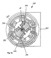
図13は、回転子装置の第1実施形態を示す。軸受け装置59は、固定軸68の一方の端部に取付けられている。固定軸68はフランジ202を備える。回転子60に接続されている軸受け203は、軸の他方の端部に取付けられている。
As can be seen from FIG. 12, a
FIG. 13 shows a first embodiment of a rotor device. The bearing
回転子60は、外側リング70に接続されている、ロータブレード又は羽根66を備える。軸受け装置59はプレート62を備える。プレート62もまた外側リンク204に接続されている。外側リング204は、流路3の外側スリーブ6の一部である。回転する外側リング70は歯車リム80を備える。歯車リム80は、周囲に同じように配置されている、単数又は複数のピニオン(図示されない)と噛合する。ピニオンのそれぞれは、発電機を駆動させる駆動軸に接続されている。
The
十分な大きさのエアギャップ205が、プレート部62と羽根部66との間に設けられている。
図14は、発電機210のもう1つの本発明による実施形態を示す。発電機210は、従来の方法で設計されている。発電機210は、励起巻線214を有する電機子又は回転子212を備える。回転子には、適切な誘導巻線が配置されている。
A sufficiently
FIG. 14 shows another embodiment of the
本発電機の特別な特徴は、図13による実施形態において、例えば、回転子212は、風力発電装置1の第3の区域11を囲むものであって、外側歯車リム80の代わりに、対応して密着した接続が用いられていることである。
A special feature of the generator is that in the embodiment according to FIG. 13, for example, the
発電機は、また、スタンド218とブラケット220とを備える。ブラケット220は、時計回りの方向に90°回転されたもので、支持軸受としても機能しうる。
それゆえ、本風力発電装置を提案することによって、より一層効率的、より一層低価格、及びより一層小型の態様によって、大気からエネルギーを回復させる可能性が創出されて、より大きな出力も構成する。
The generator also includes a
Therefore, by proposing this wind turbine generator, the possibility of recovering energy from the atmosphere is created by a more efficient, lower cost, and smaller size aspect, and also configures higher output. .
Claims (48)
一定の断面を有する第1の区域(7)であって、内部に大気が導かれることが可能であり、空気加速装置(39)が当該第1の区域(7)内に備えられている第1の区域(7)と、
ベンチュリノズル(10)の形状で設計されている第2の区域(9)と、
前記第2の区域(9)に続く第3の区域(11)であって、当該第3の区域(11)内に回転子(60)が設置され、該回転子(60)は通過して流れる空気流によって回転するようにされ、該回転子(60)の回転が電力を発生させる働きをする第3の区域(11)と、
ラバルノズル(12)の形状で設計される第4の区域(13)と、
前記流路(3)に導かれた空気を排出する働きをする第2の空気加速装置(85)を備える第5の区域(15)と
を備えることを特徴とする風力発電装置。 A wind power generator (1) for generating electric power from the atmosphere, the wind power generator (1) comprising a flow path (3) through which the atmosphere is formed by the formation of an air flow The flow path (3) has an outer sleeve (6) that forms a boundary;
A first zone (7) having a constant cross-section, through which the atmosphere can be led, and an air accelerator (39) provided in the first zone (7); 1 area (7),
A second zone (9) designed in the shape of a venturi nozzle (10);
A third section (11) following the second section (9), wherein a rotor (60) is installed in the third section (11), and the rotor (60) passes therethrough; A third zone (11) that is rotated by a flowing air stream and in which rotation of the rotor (60) serves to generate electrical power;
A fourth zone (13) designed in the shape of a Laval nozzle (12);
A wind power generator comprising: a fifth section (15) including a second air acceleration device (85) that serves to discharge air guided to the flow path (3).
前記流路(3)における前記第1の区域(7)及び前記第5の区域(15)の少なくとも一方の前記空気加速装置(39、85)が、少なくとも1つのファンを備えること
を特徴とする、風力発電装置。 The wind turbine generator according to claim 1,
The air accelerator (39, 85) in at least one of the first section (7) and the fifth section (15) in the flow path (3) includes at least one fan. Wind power generator.
前記流路(3)における前記第1の区域(7)及び前記第5の区域(15)の少なくとも一方の前記空気加速装置(39、85)の、大気の流れ方向からみて下流に、流れガイド装置(49、87)を備え、前記空気加速装置によって生じた乱れた空気流及び回転している空気流の少なくとも一方を層流へと変換させること
を特徴とする風力発電装置。 The wind turbine generator according to claim 1 or 2,
A flow guide downstream of the air acceleration device (39, 85) of at least one of the first zone (7) and the fifth zone (15) in the flow path (3) as viewed from the flow direction of the atmosphere. A wind turbine generator comprising a device (49, 87), wherein at least one of a turbulent air flow and a rotating air flow generated by the air accelerator is converted into a laminar flow.
前記流れガイド装置(49、87)は下流固定子であること
を特徴とする風力発電装置。 The wind turbine generator according to claim 3,
The wind guide generator (49, 87) is a downstream stator.
前記流れガイド装置(49、87)が、平行管装置であること
を特徴とする風力発電装置。 The wind turbine generator according to claim 3,
The wind guide generator (49, 87) is a parallel pipe device.
前記流れガイド装置が、下流固定子及び平行管装置(101、112)の両方を備えること
を特徴とする、風力発電装置。 A wind turbine generator according to any one of claims 3 to 5,
Wind power generator characterized in that the flow guide device comprises both a downstream stator and parallel tube devices (101, 112).
前記第1の区域(7)における前記空気加速装置(39)、及び、前記第5の区域(15)における前記空気加速装置(85)の少なくとも一方、の上流に、空気流を層流とするため空気ガイド装置(27、79)を備えることを特徴とする、風力発電装置。 The wind turbine generator according to any one of claims 1 to 6,
The air flow is laminar upstream of at least one of the air accelerator (39) in the first zone (7) and the air accelerator (85) in the fifth zone (15). Therefore, it is provided with an air guide apparatus (27, 79), The wind power generator characterized by the above-mentioned.
平行管装置(101、112)が、前記第5の区域(15)の前記空気ガイド装置(87)の上流に備えられていること
を特徴とする、風力発電装置。 The wind power generator according to claim 7,
A wind turbine generator, characterized in that a parallel tube device (101, 112) is provided upstream of the air guide device (87) in the fifth zone (15).
前記平行管装置(112)が、中央管の周りに同心円状に配置された複数の管(113)から形成されていること
を特徴とする、風力発電装置。 A wind turbine generator according to any one of claims 5 to 8,
The parallel tube device (112), characterized in that it is formed from a plurality of tubes disposed concentrically (113) around the central tube, the wind turbine generator.
前記流路(3)は、15°あるいは15°より小さい角度αでベンチュリノズル(9)のエリアにおいて幅狭になっていくこと
を特徴とする、風力発電装置。 It is a wind power generator according to any one of claims 1 to 9,
The wind passage (3) is narrow in the area of the venturi nozzle (9) at an angle α of 15 ° or smaller than 15 °.
前記流路(3)は、前記回転子(60)の下流の前記第4の区域(13)において、7°あるいは7°より小さい角度βで拡大すること
を特徴とする、風力発電装置。 It is a wind power generator according to any one of claims 1 to 10,
The flow path (3) expands at an angle β smaller than 7 ° or 7 ° in the fourth section (13) downstream of the rotor (60).
前記第1の区域(7)のエリアにおける前記流路(3)の直径は、前記第5の区域(15)のエリアにおける直径と同じであること
を特徴とする、風力発電装置。 It is a wind power generator according to any one of claims 1 to 11,
The diameter of the flow path (3) in the area of the first section (7) is the same as the diameter in the area of the fifth section (15).
前記流路(3)の出口(5)にかかる該断面は、前記流路(3)の前記入口(4)にかかる断面より大きい、2倍の大きさであること
を特徴とする、風力発電装置。 A wind turbine generator according to any one of claims 1 to 12,
The wind power generation characterized in that the cross section applied to the outlet (5) of the flow path (3) is twice as large as the cross section applied to the inlet (4) of the flow path (3). apparatus.
前記第1の区域(7)内の前記空気加速装置(39)に続く前記流れガイド装置(49)の下流に、先細の管状部(108)が設けられ、該先細の管状部(108)にはフローコーン(109)が設けられ、該フローコーン(109)はある点まで先細となり、該フローコーンに沿って該空気流が流れるものであって、前記フローコーン(109)の先細となる前記角度αは15°あるいは15°より小さいこと
を特徴とする風力発電装置。 The wind turbine generator according to any one of claims 3 to 13,
A tapered tubular portion (108) is provided downstream of the flow guide device (49) following the air accelerator (39) in the first zone (7), and the tapered tubular portion (108) Is provided with a flow cone (109), the flow cone (109) is tapered to a certain point, and the air flow flows along the flow cone, and the flow cone (109) is tapered. A wind power generator characterized in that the angle α is 15 ° or smaller than 15 °.
一定の断面(107)の部分には、もう1つの流れガイド装置(101、112)が設けられ、前記流路の前記先細になるあるいは幅狭になる管状部(108)の後に続き、該一定の断面(107)が設けられていること
を特徴とする風力発電装置。 The wind power generator according to claim 14,
The part of the constant cross section (107) is provided with another flow guide device (101, 112), following the tapered or narrow tubular part (108) of the flow path, The wind power generator characterized by the above-mentioned.
前記第2の区域(9)内には、先端(120)から前記回転子のハブの断面まで拡大しているコーン(119)が設けられ、該コーンの拡大角度αは、前記ベンチュリノズルの先細の角度αと同じであること
を特徴とする風力発電装置。 The wind turbine generator according to any one of claims 1 to 15,
A cone (119) is provided in the second zone (9) that extends from the tip (120) to the cross-section of the rotor hub, the angle of expansion α of the cone being the taper of the venturi nozzle. The wind power generator characterized by being the same as the angle α.
前記第4の区域(13)内には、先端(122)まで先細になっているコーン(121)が設けられ、該コーンの出口断面は、前記回転子(60)のハブにおける断面と同じであって、前記コーン(121)の先細の角度βは、前記ラバルノズルの拡張角度βと同じであること
を特徴とする風力発電装置。 The wind turbine generator according to any one of claims 1 to 16,
A cone (121) that tapers to the tip (122) is provided in the fourth zone (13), and the exit cross section of the cone is the same as that of the hub of the rotor (60). The tapered angle β of the cone (121) is the same as the expansion angle β of the Laval nozzle.
前記第4の区域(13)に隣接して、前記流路(3)の流れ鎮静部(116)が設けられ、該流れ鎮静部(116)は、一定の外径を備え、追加の流れガイド装置(124)をも備えること
を特徴とする風力発電装置。 The wind turbine generator according to any one of claims 1 to 17,
Adjacent to the fourth zone (13) is a flow calming portion (116) of the flow path (3), the flow calming portion (116) having a constant outer diameter and an additional flow guide. A wind turbine generator comprising the device (124).
前記第5の区域(15)の上流であって、前記流れガイド装置の前に、先端から角度βで拡大するコーンが備えられ、該コーンの端部断面が前記流れガイド装置(79)のハブの断面と同じであること
を特徴とする風力発電装置。 The wind turbine generator according to any one of claims 1 to 18,
A cone is provided upstream of the fifth section (15) and in front of the flow guide device, expanding at an angle β from the tip, the end section of the cone being the hub of the flow guide device (79). A wind power generator characterized by having the same cross-section as the above.
前記回転子(60)は軸(68)上に支持され、該軸(68)は、前記軸受装置(59)に回転不可能に接続され、該軸受装置(59)内に前記回転子(60)は前記流路の前記外側スリーブの一部を形成する外側管状部(70)を備え、該外部スリーブ内に前記外側管状部(70)は歯車リブ(80)を備え、該歯車リブ(80)は前記回転子(60)の回転を歯車部によって発電機へ伝達する働きをすること
を特徴とする、風力発電装置。 The wind turbine generator according to any one of claims 1 to 19,
The rotor (60) is supported on a shaft (68), and the shaft (68) is non-rotatably connected to the bearing device (59), and the rotor (60) is placed in the bearing device (59). ) Comprises an outer tubular part (70) forming part of the outer sleeve of the flow path, the outer tubular part (70) comprising a gear rib (80) in the outer sleeve, the gear rib (80 ) Acts to transmit the rotation of the rotor (60) to the generator through a gear unit.
前記回転子(60)の回転動作を伝達するために、少なくとも2つの、ピニオンであって、外周に等しく配列されているピニオンが設けられ、それぞれの前記ピニオンは駆動軸に接続され、それぞれの前記駆動軸は発電機に接続されていること
を特徴とする、風力発電装置。 The wind turbine generator according to claim 20,
In order to transmit the rotational movement of the rotor (60), at least two pinions, which are arranged equally on the outer circumference, are provided, each of the pinions being connected to a drive shaft, A wind power generator characterized in that the drive shaft is connected to a generator.
前記第3の区域(11)は、前記回転子(60)の回転を少なくとも1つの出力軸(71)の回転動作へ変換する歯車部(63)を備え、該出力軸(71)は、前記流路(3)から垂直に延出し、発電機(23)を駆動させる働きをするものであること
を特徴とする風力発電装置。 The wind turbine generator according to any one of claims 1 to 19,
The third section (11) includes a gear portion (63) that converts the rotation of the rotor (60) into a rotational motion of at least one output shaft (71), and the output shaft (71) A wind turbine generator that extends vertically from the flow path (3) and functions to drive the generator (23) .
前記歯車部(63)は、筐体(65)を備え、該筐体(65)内に軸(67)が支持され、該軸(67)の一方の端部は前記筐体の外で回転子(6)と接続され、他方の端部は90°をなしている取出軸(71)に接続されており、前記歯車部の前記筐体(65)は、軸受板(62)を有する軸受装置(59)内に支持され、該軸受板は前記流路(3)の前記外側スリーブ(6)に接続されていること
を特徴とする、風力発電装置。 The wind turbine generator according to claim 22,
The gear portion (63) includes a housing (65), and a shaft (67) is supported in the housing (65), and one end of the shaft (67) rotates outside the housing. The housing (65) of the gear portion has a bearing plate (62). The housing (65) of the gear portion is connected to the take-out shaft (71) connected to the child (6) and the other end thereof is 90 °. A wind turbine generator supported by a device (59), wherein the bearing plate is connected to the outer sleeve (6) of the flow path (3).
前記回転子は軸に取り付けられ、該軸は回転不可能に前記軸受装置に接続され、該軸受装置内に、前記回転子は外側部を備え、該外側部は前記発電機の前記回転子及び前記電機子の少なくとも一方を駆動させること
を特徴とする風力発電装置。 The wind turbine generator according to any one of claims 1 to 19,
The rotor is attached to a shaft, and the shaft is non-rotatably connected to the bearing device, and in the bearing device, the rotor includes an outer portion, and the outer portion includes the rotor of the generator and A wind turbine generator that drives at least one of the armatures.
前記風力発電装置はスタンド(135)内に配置され、該スタンドは回転可能に支持されていること
を特徴とする、風力発電装置。 A wind turbine generator according to any one of claims 1 to 24,
The wind power generator is disposed in a stand (135), and the stand is rotatably supported.
前記スタンドが、底部壁(137)と、屋根部(136)と、複数の支柱(138)とを有し、前記流路(3)の前記第1から第5の区域(7、9、11、13、15)が最外の前記支柱の間に配置されていること
を特徴とする風力発電装置。 The wind turbine generator according to claim 25,
The stand includes a bottom wall (137), a roof portion (136), and a plurality of struts (138), and the first to fifth sections (7, 9, 11) of the flow path (3). , 13, 15) a wind power generator, wherein a is disposed between the outermost of said strut.
当該風力発電装置(1)は、前記底板(137)から一定の間隙をあけて配置されていること
を特徴とする風力発電装置。 The wind turbine generator according to claim 26,
The wind power generator (1) is arranged with a certain gap from the bottom plate (137).
追加のベンチュリノズル(141)が前記空気流入口側(4)に備えられていること
を特徴とする、風力発電装置。 The wind turbine generator according to any one of claims 25 to 27,
Wind turbine generator, characterized in that an additional venturi nozzle (141) is provided on the air inlet side (4).
追加のラバルノズル(142)が前記空気排出側(5)に備えられていること
を特徴とする風力発電装置。 The wind turbine generator according to any one of claims 25 to 28,
A wind power generator characterized in that an additional Laval nozzle (142) is provided on the air discharge side (5).
前記回転可能なスタンド(135)は、液体(156)に浮かぶ回転可能な浮揚ユニット(146)を備えること
を特徴とする、風力発電装置。 A wind turbine generator according to any one of claims 25 to 29,
The rotatable stand (135) includes a rotatable levitation unit (146) floating in a liquid (156).
前記液体(156)は、円形の枡体(155)内に保持され、該枡体(155)内に前記浮揚ユニット(146)が配置されていること
を特徴とする、風力発電装置。 The wind turbine generator according to claim 30, wherein
The said liquid (156) is hold | maintained in the circular housing | casing (155), The said levitation | floating unit (146) is arrange | positioned in this housing | casing (155), The wind power generator characterized by these.
キングピン(157)が、前記浮揚ユニット(146)の底板(147)から下方に突出し、軸受ブロック(160)内に形成されている軸受(159)内に回転可能に支持されていること
を特徴とする風力発電装置。 The wind turbine generator according to any one of claims 25 to 31,
The king pin (157) protrudes downward from the bottom plate (147) of the levitation unit (146) and is rotatably supported in a bearing (159) formed in the bearing block (160). Wind power generator.
周形の軸受部(161)が、前記浮揚ユニット(146)の側壁(148)と枡体(155)との間で、前記液体(158)の水面より上方に配置されていること
を特徴とする風力発電装置。 A wind turbine generator according to claim 32,
A circumferential bearing portion (161) is disposed above the water surface of the liquid (158) between the side wall (148) and the housing (155) of the levitation unit (146). Wind power generator.
当該風力発電装置が垂直方向に配置されていること
を特徴とする風力発電装置。 A wind turbine generator according to any one of claims 1 to 33,
A wind power generator characterized in that the wind power generator is arranged in a vertical direction.
半円形状の設計である空気供給装置(190)が、当該風力発電装置(1)の上方入口に備えられていること
を特徴とする風力発電装置。 A wind turbine generator according to claim 3 4,
A wind power generator characterized in that an air supply device (190) having a semicircular design is provided at an upper entrance of the wind power generator (1).
フロー偏向装置(192)は、前記出口側(5)に備えられ、垂直方向から水平方向へ流出される空気流を偏向させる流路(193)を備えること
を特徴とする風力発電装置。 The wind power generator according to claim 34 or claim 35,
Flow deflector (192) is provided in the outlet side (5), a wind power generator, characterized in that it comprises flow path for deflecting the air flow flowing out to the vertical direction or et water Rights direction (193).
前記流路(193)は偏向体(194)内に配置され、該偏向体(194)の周りで大気が流れること
を特徴とする風力発電装置。 The wind turbine generator according to claim 36,
The said flow path (193) is arrange | positioned in a deflecting body (194), and an airflow flows around this deflecting body (194), The wind power generator characterized by the above-mentioned.
前記流路(193)が流れ方向に拡張し、追加の空気加速装置(195)を備えること
を特徴とする風力発電装置。 A wind turbine generator according to claim 36 or claim 37,
A wind power generator characterized in that the flow path (193) extends in the flow direction and is provided with an additional air acceleration device (195).
前記流路(193)の、流れの方向に対して下流において、いくつかのバッフルプレート(196)が配置され、該バッフルプレート(196)は、前記流路(193)の断面部を越えて突出していること
を特徴とする風力発電装置。 A wind turbine generator according to any one of claims 36 to 38,
A number of baffle plates (196) are arranged downstream of the flow path (193) with respect to the flow direction, and the baffle plates (196) protrude beyond the cross section of the flow path (193). Wind power generator characterized by that.
当該装置を大気の最適な流れ方向に配向し保持する働きをする帆(191)が、当該風力発電装置(1)に取付けられていること
を特徴とする風力発電装置。 A wind turbine generator according to any one of claims 34 to 39,
A wind power generator characterized in that a sail (191), which serves to orient and hold the device in an optimum flow direction of the atmosphere, is attached to the wind power generator (1).
請求項1から40のいずれか1つに記載の、複数の風力発電装置(1)を備え、該複数の風力発電装置が互いに上にあるいは隣に配置されていること
を特徴とする風力発電装置システム。 A wind power generation system (170) for generating electric power using the atmosphere,
Wind turbine generator comprising a plurality of wind turbine generators (1) according to any one of claims 1 to 40, wherein the turbine generators are arranged on top of each other or next to each other. system.
スタンドを備え、該スタンド内に、互いに上にあるいは隣に配置されている前記風力発電装置(1)が回転可能に支持されていること
を特徴とする、風力発電装置システム。 The wind turbine generator system according to claim 41,
A wind turbine generator system comprising a stand, wherein the wind turbine generators (1) arranged on or next to each other are rotatably supported in the stand.
大気を流路(3)の第1の区域(7)へ導くステップと、
前記流路(3)の前記第1の区域(7)に設置された加速装置(39)によって空気流を加速するステップと、
ベンチュリノズルの形状である前記流路における圧縮によって、前記流路(3)の前記第2の区域(9)で前記空気流をさらに加速するステップと、
前記流路(3)の第3の区域(11)を通って該空気流と、該区域にある回転子(60)の駆動を伝達するステップと、
ラバルノズルの形状で設計されている、前記流路(3)の第4の区域(13)へ該空気流を排出するステップと、
前記流路(3)の第5の区域(15)で該空気流を再び加速するステップと、
外気へと該空気流を排出し、前記流路を通る通路中で該空気流から運動エネルギー及び熱エネルギーの両方を抽出するステップと
を含むことを特徴とする、移動する大気から電力を発生させるための方法。 A method for generating power from a moving atmosphere,
Directing the atmosphere to the first zone (7) of the flow path (3);
Accelerating the air flow by means of an accelerating device (39) installed in the first zone (7) of the flow path (3);
Further accelerating the air flow in the second zone (9) of the flow path (3) by compression in the flow path in the shape of a venturi nozzle;
Transmitting the air flow through the third zone (11) of the flow path (3) and the drive of the rotor (60) in the zone;
Discharging the air flow into a fourth zone (13) of the flow path (3), designed in the form of a Laval nozzle;
Accelerating the air flow again in a fifth zone (15) of the flow path (3);
Exhausting the air flow to the outside air and extracting both kinetic and thermal energy from the air flow in the passage through the flow path to generate power from the moving atmosphere Way for.
前記流路における前記第1の区域(7)及び前記第5の区域(15)の少なくとも一方の前記加速装置(39、85)の上流において、流入された空気が層流として整流されること
を特徴とする、移動する大気から電力を発生させるための方法。 44. The method of claim 43, comprising:
Inflow air is rectified as a laminar flow upstream of the acceleration device (39, 85 ) in at least one of the first zone (7) and the fifth zone (15) in the flow path. A method for generating power from a moving atmosphere, characterized.
前記流路における前記第1の区域(7)及び前記第5の区域(15)の少なくとも一方の前記加速装置(39、85)の下流において、通過して流れる空気が再び層流として整流されること
を特徴とする、移動する大気から電力を発生させるための方法。 45. A method according to claim 43 or claim 44, comprising:
At least one of the first zone (7) and the fifth zone (15) in the flow path downstream of the accelerator (39, 85 ), the air flowing therethrough is rectified again as a laminar flow. A method for generating electrical power from a moving atmosphere.
空気流が前記流路の前記第3の区域(11)へ流入する時までに該空気流が所定の速度に達するように、前記流路の前記第1の区域及び前記第2の区域において、該空気流が加速されること
を特徴とする、移動する大気から電力を発生させるための方法。 A method according to any one of claims 43 to 45, comprising:
In the first area and the second area of the flow path, such that the air flow reaches a predetermined speed by the time the air flow enters the third area (11) of the flow path, A method for generating electric power from a moving atmosphere, characterized in that the air flow is accelerated.
前記第5の区域によって、前記第4の区域内に負圧を発生させること
を特徴とする、移動する大気から電力を発生させるための方法。 A method according to any one of claims 43 to 46, comprising:
A method for generating electrical power from a moving atmosphere, characterized in that the fifth zone generates a negative pressure in the fourth zone.
電力を発生させるプロセスの開始時に、外部からの力によって加速装置が駆動され、安定した電力の発生状態に到達した後、該加速装置には発生させた電力が供給されること
を特徴とする。移動する大気から電力を発生させるための方法。 48. A method according to any one of claims 43 to 47, comprising:
At the start of a process for generating electric power, the acceleration device is driven by an external force, and after reaching a stable electric power generation state, the generated electric power is supplied to the acceleration device. A method for generating power from moving air.
Applications Claiming Priority (3)
| Application Number | Priority Date | Filing Date | Title |
|---|---|---|---|
| EP06022558A EP1916415B1 (en) | 2006-10-28 | 2006-10-28 | Windturbine and method for producing electricity from surrounding moving air |
| EP06022558.8 | 2006-10-28 | ||
| PCT/EP2007/009331 WO2008052713A1 (en) | 2006-10-28 | 2007-10-26 | Wind power installation, generator for generation of electrical power from ambient air, and method for generation of electrical power from ambient air in motion |
Publications (3)
| Publication Number | Publication Date |
|---|---|
| JP2010508459A JP2010508459A (en) | 2010-03-18 |
| JP2010508459A5 JP2010508459A5 (en) | 2010-12-16 |
| JP5258774B2 true JP5258774B2 (en) | 2013-08-07 |
Family
ID=37897437
Family Applications (1)
| Application Number | Title | Priority Date | Filing Date |
|---|---|---|---|
| JP2009533744A Expired - Fee Related JP5258774B2 (en) | 2006-10-28 | 2007-10-26 | Wind power generator, generator for generating power from the atmosphere, and method for generating power from the moving atmosphere |
Country Status (17)
| Country | Link |
|---|---|
| US (1) | US8310072B2 (en) |
| EP (1) | EP1916415B1 (en) |
| JP (1) | JP5258774B2 (en) |
| KR (1) | KR20090083421A (en) |
| CN (1) | CN101542115B (en) |
| AT (1) | ATE474138T1 (en) |
| AU (1) | AU2007315295B2 (en) |
| BR (1) | BRPI0718430A2 (en) |
| CA (1) | CA2667672C (en) |
| CU (1) | CU23843A3 (en) |
| DE (1) | DE502006007442D1 (en) |
| IL (1) | IL198324B (en) |
| MX (1) | MX2009004581A (en) |
| NZ (1) | NZ577120A (en) |
| RU (1) | RU2493427C2 (en) |
| WO (1) | WO2008052713A1 (en) |
| ZA (1) | ZA200903627B (en) |
Families Citing this family (27)
| Publication number | Priority date | Publication date | Assignee | Title |
|---|---|---|---|---|
| DE102007034618A1 (en) * | 2007-07-25 | 2009-01-29 | Georg Hamann | Device for generating energy from a fluid flow |
| DE102009015926A1 (en) * | 2009-04-01 | 2010-10-07 | Schuler Pressen Gmbh & Co. Kg | Gondola with multipart main shaft |
| WO2010135409A2 (en) * | 2009-05-20 | 2010-11-25 | Energy Tunnel, Inc. | Systems and methods for converting energy |
| DE102010024621B4 (en) * | 2010-03-08 | 2016-06-30 | Gebhard Bernsau | energy converters |
| US8061986B2 (en) * | 2010-06-11 | 2011-11-22 | General Electric Company | Wind turbine blades with controllable aerodynamic vortex elements |
| US8814493B1 (en) * | 2010-07-02 | 2014-08-26 | William Joseph Komp | Air-channeled wind turbine for low-wind environments |
| IT1404013B1 (en) * | 2010-12-23 | 2013-11-08 | Biagini | WIND MACHINE WITH AERODYNAMIC ELEMENTS TO CONCENTRATE AND ACCELERATE A WIND FLOW ENTERING OUTSIDE. |
| US9631601B2 (en) | 2012-01-25 | 2017-04-25 | Georg Reitz | Wind power installation |
| US20140064958A1 (en) * | 2012-08-31 | 2014-03-06 | Ge Aviation Systems Llc | Fan assembly |
| HRP20211699T1 (en) * | 2015-03-05 | 2022-02-04 | Gaia S.R.L. | Wind power system |
| US10060647B2 (en) * | 2015-10-16 | 2018-08-28 | Primo Wind, Inc. | Rooftop exhaust collectors and power generators, and associated systems and methods |
| US10767622B2 (en) * | 2016-02-01 | 2020-09-08 | Roger Gordon Phillips | Highly efficient wind turbine |
| CN107917038A (en) * | 2016-10-09 | 2018-04-17 | 吴廷清 | Negative pressure type wave power generation device |
| US10221833B2 (en) * | 2017-01-25 | 2019-03-05 | Walter Jeffrey Shakespeare | Sail based wind energy system |
| RU175712U1 (en) * | 2017-03-13 | 2017-12-15 | Федеральное государственное бюджетное образовательное учреждение высшего образования "Казанский национальный исследовательский технический университет им. А.Н. Туполева-КАИ" (КНИТУ-КАИ) | Wind turbine |
| US11053704B1 (en) | 2017-10-31 | 2021-07-06 | Pecos Wind Power, Inc. | Fixture for tilt-up wind turbine installation |
| RU2750480C2 (en) * | 2017-11-07 | 2021-06-28 | Анатолий Евгеньевич Волков | Method and apparatus for generation of electric power |
| US20190242359A1 (en) * | 2017-12-12 | 2019-08-08 | John Oscar RIDER | Wind-tunnel turbine vacuum air flow generator |
| CN107989745B (en) * | 2017-12-30 | 2023-08-29 | 长沙紫宸科技开发有限公司 | Portable wind collecting duct wind power generator |
| WO2019162386A1 (en) | 2018-02-22 | 2019-08-29 | KLUGE, Carl-Ernst | Wind turbine |
| US10738758B2 (en) * | 2018-06-29 | 2020-08-11 | MJ Stewart Investments, LLC | Funnel wind turbine |
| US20200102931A1 (en) * | 2018-10-02 | 2020-04-02 | Edward John Koch | Wind Turbine |
| IT201900008895A1 (en) * | 2019-06-13 | 2020-12-13 | Marco Paolo Fabrizio De | Vertical axis conveyor for wind turbines |
| US20200412161A1 (en) * | 2019-06-28 | 2020-12-31 | K&N Engineering, Inc. | Side mirror wind turbine |
| EP3916215B1 (en) * | 2019-08-20 | 2023-10-18 | Calle Madrid, Alfredo Raúl | Wind wall |
| TWI811441B (en) * | 2019-08-28 | 2023-08-11 | 克米龍有限公司 | Electrical vehicle with power generating device by vortex flow |
| DE102021005200A1 (en) | 2021-10-19 | 2023-04-20 | Gebhard Bernsau | Device for converting flow energy transported through a medium into mechanical and/or electrical energy |
Family Cites Families (48)
| Publication number | Priority date | Publication date | Assignee | Title |
|---|---|---|---|---|
| US1200308A (en) | 1915-07-01 | 1916-10-03 | John C Bunnell | Water-motor. |
| US1234405A (en) | 1915-12-01 | 1917-07-24 | Zeno La Brier | Windmill. |
| US1441774A (en) | 1920-12-15 | 1923-01-09 | Omer T Adams | Wind motor |
| US1812741A (en) | 1930-01-31 | 1931-06-30 | Espinosa Eduardo Jimenez | Windmill |
| US1974008A (en) | 1933-01-25 | 1934-09-18 | Biehn Warren | Wind turbine |
| US2431111A (en) | 1943-12-16 | 1947-11-18 | Brie Stanley R Du | Wind motor |
| US4079264A (en) | 1976-05-03 | 1978-03-14 | Nathan Cohen | Wind or water operated power plant |
| US4159426A (en) * | 1977-03-07 | 1979-06-26 | Staton Ronald R | Energy conversion system |
| DE2717043A1 (en) * | 1977-04-18 | 1978-10-19 | Ludwig Naake | Wind driven power generator - has impeller within jet shaped housing to concentrate wind for increased output |
| US4134707A (en) | 1977-04-26 | 1979-01-16 | Ewers Marion H | Wind turbine apparatus |
| US4220870A (en) | 1978-06-22 | 1980-09-02 | Kelly Donald A | Wind conversion lattice array, with multiple mini-turbo-generator modules |
| US4245958A (en) | 1978-11-22 | 1981-01-20 | Ewers Marion H | Vertical axis wind turbine |
| US4288200A (en) | 1979-04-25 | 1981-09-08 | Hare Louis R O | Wind tower turbine |
| JPS55164783A (en) * | 1979-06-07 | 1980-12-22 | Masabumi Ishimura | Wind force power generator |
| WO1981000887A1 (en) * | 1979-09-28 | 1981-04-02 | R Rougemont | Station for collecting wind energy |
| US4474529A (en) | 1983-03-21 | 1984-10-02 | Kinsey Lewis R | Windmill |
| JPS6040785A (en) * | 1983-08-12 | 1985-03-04 | Takashi Take | Wind mill generator |
| US4609827A (en) | 1984-10-09 | 1986-09-02 | Nepple Richard E | Synchro-vane vertical axis wind powered generator |
| US4715776A (en) | 1985-11-22 | 1987-12-29 | Benesh Alvin H | Wind turbine system using a savonius type rotor |
| GB8626347D0 (en) | 1986-11-04 | 1986-12-03 | Bicc Plc | Wind energy convertor |
| US5037268A (en) | 1988-05-31 | 1991-08-06 | Fenlon Robert M | Dual axis wind turbine |
| DE8902056U1 (en) * | 1989-02-22 | 1990-06-21 | Carl Hurth Maschinen- und Zahnradfabrik GmbH & Co, 8000 München | Device for testing synchronization units |
| US5336933A (en) | 1990-07-16 | 1994-08-09 | Bru-Mel Corporation | Fluid-augmented free-vortex power generating apparatus |
| US5246342A (en) | 1992-07-09 | 1993-09-21 | Bergstein Frank D | Wind rotor apparatus |
| US5300817A (en) * | 1993-04-16 | 1994-04-05 | Baird William R | Solar venturi turbine |
| US5664418A (en) | 1993-11-24 | 1997-09-09 | Walters; Victor | Whirl-wind vertical axis wind and water turbine |
| FR2738283B1 (en) * | 1995-08-30 | 1997-09-26 | Snecma | TURBOMACHINE ARRANGEMENT INCLUDING A VANE GRILLE AND AN INTERMEDIATE HOUSING |
| CA2268805C (en) * | 1996-10-22 | 2002-09-24 | Germaine Van Der Veken | Hooded wind power engine |
| NL1013559C2 (en) * | 1999-11-11 | 2001-05-28 | Peter Alexander Josephus Pas | System for producing hydrogen from water using a water stream such as a wave stream or tidal stream. |
| JP3068946U (en) * | 1999-11-12 | 2000-05-26 | 直義 細田 | Wind power generator |
| ES2160078B1 (en) * | 1999-11-23 | 2002-05-01 | Marrero O Shanahan Pedro M | WIND TOWER WITH FLOW ACCELERATION. |
| DE10043593B4 (en) * | 2000-09-01 | 2014-01-09 | Renk Ag | Transmission for wind generators |
| JP3774760B2 (en) * | 2001-04-23 | 2006-05-17 | 国立大学法人 琉球大学 | Vortex ring device |
| US6857846B2 (en) | 2001-06-19 | 2005-02-22 | Lewis H. Miller | Stackable vertical axis windmill |
| US6929777B1 (en) * | 2001-07-26 | 2005-08-16 | Ension, Inc. | Pneumatically actuated integrated life support system |
| US6836028B2 (en) * | 2001-10-29 | 2004-12-28 | Frontier Engineer Products | Segmented arc generator |
| US20030156938A1 (en) * | 2002-02-15 | 2003-08-21 | Verini Nicholas A. | Apparatus for capturing and harnessing the energy from environmental wind |
| US7042109B2 (en) * | 2002-08-30 | 2006-05-09 | Gabrys Christopher W | Wind turbine |
| US6948905B2 (en) | 2002-09-06 | 2005-09-27 | Horjus Thomas W | Horizontal wind generator |
| US20040247438A1 (en) * | 2003-02-20 | 2004-12-09 | Mccoin Dan Keith | Wind energy conversion system |
| US6955049B2 (en) * | 2003-05-29 | 2005-10-18 | Krouse Wayne F | Machine and system for power generation through movement of water |
| US6984899B1 (en) | 2004-03-01 | 2006-01-10 | The United States Of America As Represented By The Secretary Of The Navy | Wind dam electric generator and method |
| US7381129B2 (en) * | 2004-03-15 | 2008-06-03 | Airius, Llc. | Columnar air moving devices, systems and methods |
| US7008171B1 (en) | 2004-03-17 | 2006-03-07 | Circle Wind Corp. | Modified Savonius rotor |
| US7663261B2 (en) * | 2005-02-15 | 2010-02-16 | Spiroflo, Inc. | Flow development and cogeneration chamber |
| US20070029807A1 (en) | 2005-08-08 | 2007-02-08 | Clayton Kass | Methods and systems for generating wind energy |
| US7843077B2 (en) * | 2007-05-16 | 2010-11-30 | Arduini Douglas P | Pulsed energy transfer |
| US8338975B2 (en) * | 2008-09-12 | 2012-12-25 | AGlobal Tech, LLC | Supplemental power source |
-
2006
- 2006-10-28 EP EP06022558A patent/EP1916415B1/en not_active Not-in-force
- 2006-10-28 AT AT06022558T patent/ATE474138T1/en active
- 2006-10-28 DE DE502006007442T patent/DE502006007442D1/en active Active
-
2007
- 2007-10-26 RU RU2009119916/06A patent/RU2493427C2/en not_active IP Right Cessation
- 2007-10-26 CA CA2667672A patent/CA2667672C/en not_active Expired - Fee Related
- 2007-10-26 WO PCT/EP2007/009331 patent/WO2008052713A1/en active Application Filing
- 2007-10-26 US US12/312,155 patent/US8310072B2/en not_active Expired - Fee Related
- 2007-10-26 MX MX2009004581A patent/MX2009004581A/en active IP Right Grant
- 2007-10-26 AU AU2007315295A patent/AU2007315295B2/en not_active Ceased
- 2007-10-26 NZ NZ577120A patent/NZ577120A/en not_active IP Right Cessation
- 2007-10-26 JP JP2009533744A patent/JP5258774B2/en not_active Expired - Fee Related
- 2007-10-26 CN CN2007800399664A patent/CN101542115B/en not_active Expired - Fee Related
- 2007-10-26 KR KR1020097010985A patent/KR20090083421A/en not_active Application Discontinuation
- 2007-10-26 BR BRPI0718430-1A2A patent/BRPI0718430A2/en not_active Application Discontinuation
-
2009
- 2009-04-23 CU CU2009000065A patent/CU23843A3/en active IP Right Grant
- 2009-04-23 IL IL198324A patent/IL198324B/en not_active IP Right Cessation
- 2009-05-26 ZA ZA200903627A patent/ZA200903627B/en unknown
Also Published As
| Publication number | Publication date |
|---|---|
| IL198324B (en) | 2018-10-31 |
| EP1916415A1 (en) | 2008-04-30 |
| US8310072B2 (en) | 2012-11-13 |
| RU2493427C2 (en) | 2013-09-20 |
| DE502006007442D1 (en) | 2010-08-26 |
| US20100060012A1 (en) | 2010-03-11 |
| KR20090083421A (en) | 2009-08-03 |
| AU2007315295B2 (en) | 2013-06-13 |
| RU2009119916A (en) | 2010-12-10 |
| IL198324A0 (en) | 2010-04-15 |
| CA2667672A1 (en) | 2008-05-08 |
| WO2008052713A1 (en) | 2008-05-08 |
| ZA200903627B (en) | 2010-04-28 |
| JP2010508459A (en) | 2010-03-18 |
| CN101542115A (en) | 2009-09-23 |
| CN101542115B (en) | 2013-07-17 |
| BRPI0718430A2 (en) | 2013-11-12 |
| EP1916415B1 (en) | 2010-07-14 |
| ATE474138T1 (en) | 2010-07-15 |
| MX2009004581A (en) | 2009-08-12 |
| CA2667672C (en) | 2016-07-05 |
| CU23843A3 (en) | 2012-10-15 |
| NZ577120A (en) | 2012-06-29 |
| AU2007315295A1 (en) | 2008-05-08 |
Similar Documents
| Publication | Publication Date | Title |
|---|---|---|
| JP5258774B2 (en) | Wind power generator, generator for generating power from the atmosphere, and method for generating power from the moving atmosphere | |
| JP5289770B2 (en) | Omnidirectional wind turbine | |
| TWI653390B (en) | Wind power installation | |
| JP2007528467A (en) | Wind turbine in wind tunnel | |
| US9932959B2 (en) | Shrounded wind turbine configuration with nozzle augmented diffuser | |
| US9243610B2 (en) | Fluid powered turbine | |
| EA001034B1 (en) | Windmill power plant | |
| JP2010508459A5 (en) | ||
| CN103703245A (en) | Systems, devices and methods for improving efficiency of wind power generation systems | |
| JP2019060345A (en) | Wind-powered tower with gyro-milled wind turbine | |
| KR20110000643A (en) | wind turbine | |
| US20080240916A1 (en) | System and apparatus for improved turbine pressure and pressure drop control | |
| WO2010051647A1 (en) | Turbine annular axial rotor | |
| EP3029316A1 (en) | Wind power generation tower | |
| KR102026954B1 (en) | System of wind focus type electricity from wind energy | |
| CN116950844A (en) | Eddy current power generation structure | |
| RU2714023C1 (en) | Wind-driven power plant | |
| JP2007154759A (en) | Hybrid type wind power generating device | |
| RU2182985C1 (en) | Vortex windmill | |
| RO127313A0 (en) | Wind turbine with two coaxial counter-rotating rotors and deflector-confuser | |
| KR101372250B1 (en) | Wind power generation tower with giromill | |
| WO2018189347A1 (en) | Vertical axis media-flow turbine |
Legal Events
| Date | Code | Title | Description |
|---|---|---|---|
| A521 | Request for written amendment filed |
Free format text: JAPANESE INTERMEDIATE CODE: A523 Effective date: 20101026 |
|
| A621 | Written request for application examination |
Free format text: JAPANESE INTERMEDIATE CODE: A621 Effective date: 20101026 |
|
| A977 | Report on retrieval |
Free format text: JAPANESE INTERMEDIATE CODE: A971007 Effective date: 20120822 |
|
| A131 | Notification of reasons for refusal |
Free format text: JAPANESE INTERMEDIATE CODE: A131 Effective date: 20120828 |
|
| A601 | Written request for extension of time |
Free format text: JAPANESE INTERMEDIATE CODE: A601 Effective date: 20121120 |
|
| A602 | Written permission of extension of time |
Free format text: JAPANESE INTERMEDIATE CODE: A602 Effective date: 20121128 |
|
| A601 | Written request for extension of time |
Free format text: JAPANESE INTERMEDIATE CODE: A601 Effective date: 20121219 |
|
| A602 | Written permission of extension of time |
Free format text: JAPANESE INTERMEDIATE CODE: A602 Effective date: 20121227 |
|
| A521 | Request for written amendment filed |
Free format text: JAPANESE INTERMEDIATE CODE: A523 Effective date: 20130228 |
|
| TRDD | Decision of grant or rejection written | ||
| A01 | Written decision to grant a patent or to grant a registration (utility model) |
Free format text: JAPANESE INTERMEDIATE CODE: A01 Effective date: 20130326 |
|
| A61 | First payment of annual fees (during grant procedure) |
Free format text: JAPANESE INTERMEDIATE CODE: A61 Effective date: 20130423 |
|
| FPAY | Renewal fee payment (event date is renewal date of database) |
Free format text: PAYMENT UNTIL: 20160502 Year of fee payment: 3 |
|
| R150 | Certificate of patent or registration of utility model |
Ref document number: 5258774 Country of ref document: JP Free format text: JAPANESE INTERMEDIATE CODE: R150 Free format text: JAPANESE INTERMEDIATE CODE: R150 |
|
| R250 | Receipt of annual fees |
Free format text: JAPANESE INTERMEDIATE CODE: R250 |
|
| R250 | Receipt of annual fees |
Free format text: JAPANESE INTERMEDIATE CODE: R250 |
|
| R250 | Receipt of annual fees |
Free format text: JAPANESE INTERMEDIATE CODE: R250 |
|
| LAPS | Cancellation because of no payment of annual fees |